Embed Size (px)
Citation preview

Geometric Optics
• This chapter covers how images form when light bounces off mirrors and refracts through lenses.
• There are two different kinds of images:– A real image is formed when light rays pass
through and diverge from the image point. – A virtual image is formed when the light rays
do not pass through the image point but appear to diverge from that point.
Geometric Optics
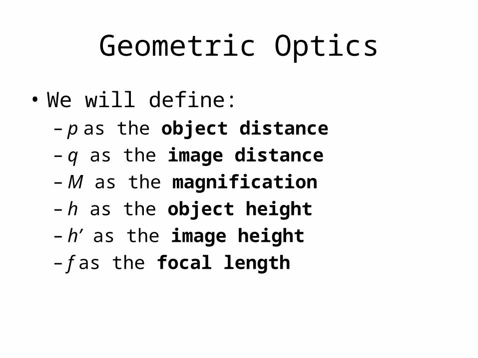
• We will define:– p as the object distance– q as the image distance– M as the magnification– h as the object height– h’ as the image height– f as the focal length
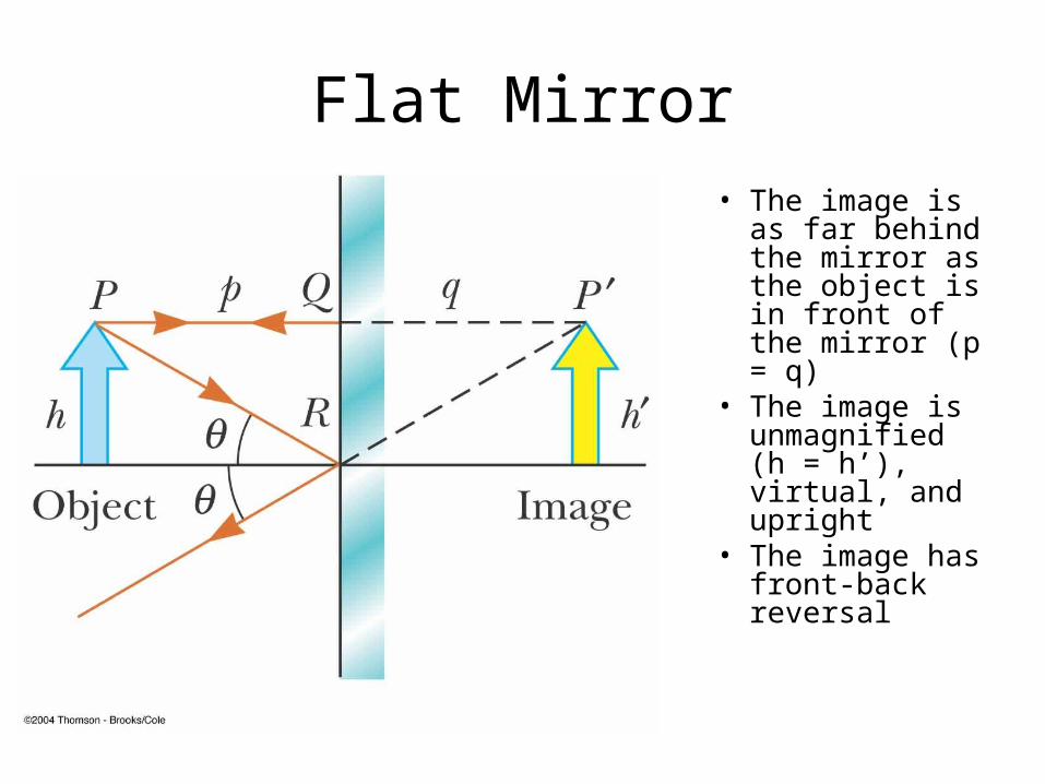
Flat Mirror
• The image is as far behind the mirror as the object is in front of the mirror (p = q)
• The image is unmagnified (h = h’), virtual, and upright
• The image has front-back reversal
Flat Mirrors
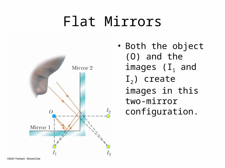
• Both the object (O) and the images (I1 and I2) create images in this two-mirror configuration.
Magnification
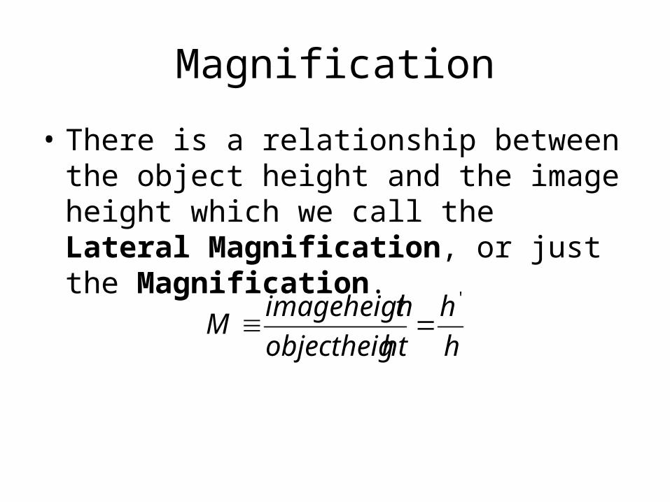
• There is a relationship between the object height and the image height which we call the Lateral Magnification, or just the Magnification.
h
h
htobjectheig
timageheighM
'
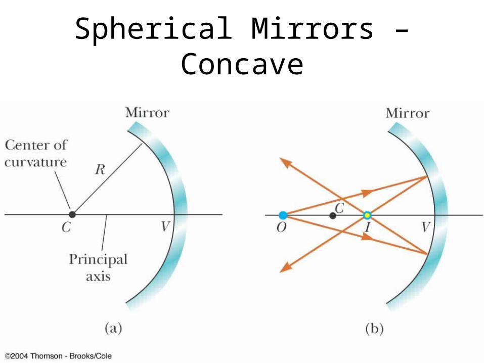
Spherical Mirrors – Concave
Spherical Mirror - Concave
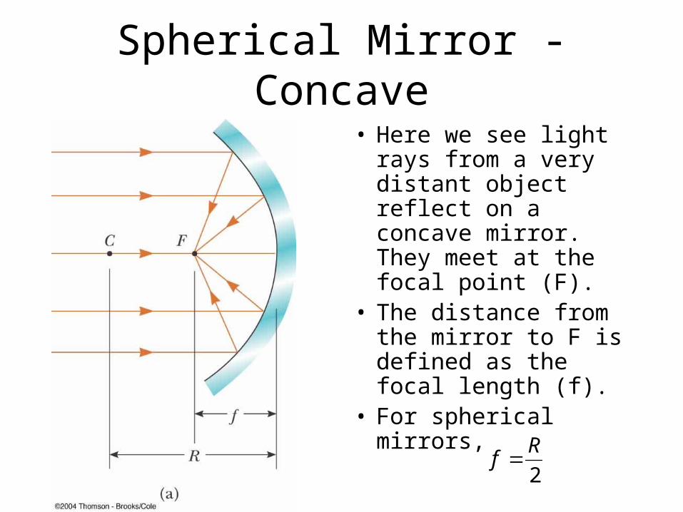
• Here we see light rays from a very distant object reflect on a concave mirror. They meet at the focal point (F).
• The distance from the mirror to F is defined as the focal length (f).
• For spherical mirrors,
2
Rf
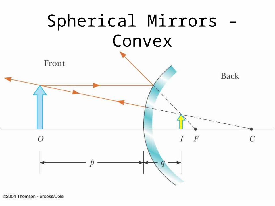
Spherical Mirrors – Convex
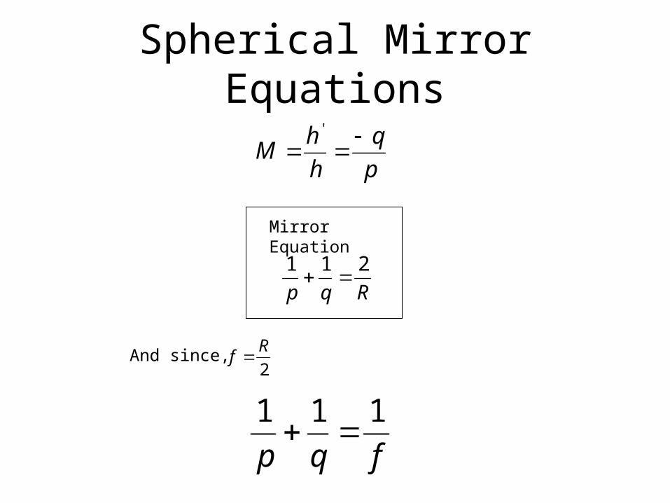
Spherical Mirror Equations
p
q
h
hM
'
Mirror Equation
Rqp
211
2
Rf And since,
fqp
111
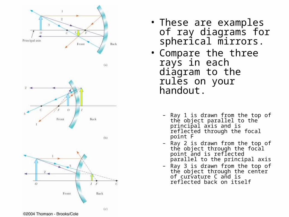
• These are examples of ray diagrams for spherical mirrors.
• Compare the three rays in each diagram to the rules on your handout.
– Ray 1 is drawn from the top of the object parallel to the principal axis and is reflected through the focal point F
– Ray 2 is drawn from the top of the object through the focal point and is reflected parallel to the principal axis
– Ray 3 is drawn from the top of the object through the center of curvature C and is reflected back on itself
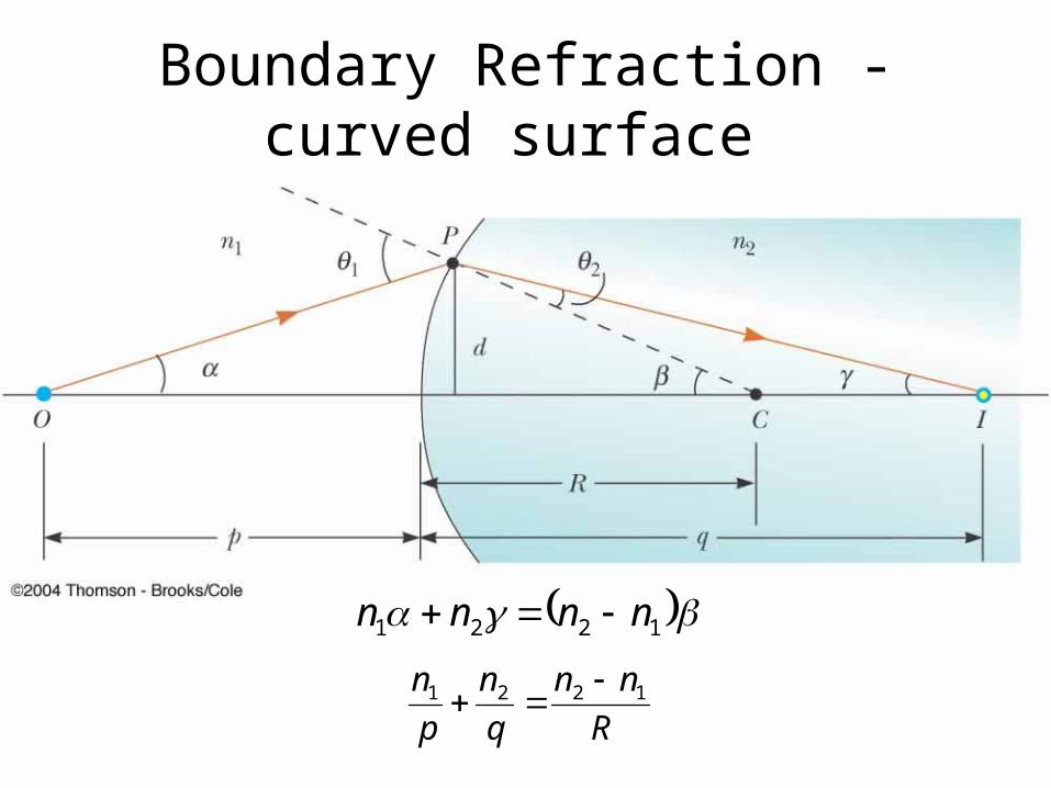
Boundary Refraction - curved surface
1221 nnnn
R
nn
q
n
p
n 1221
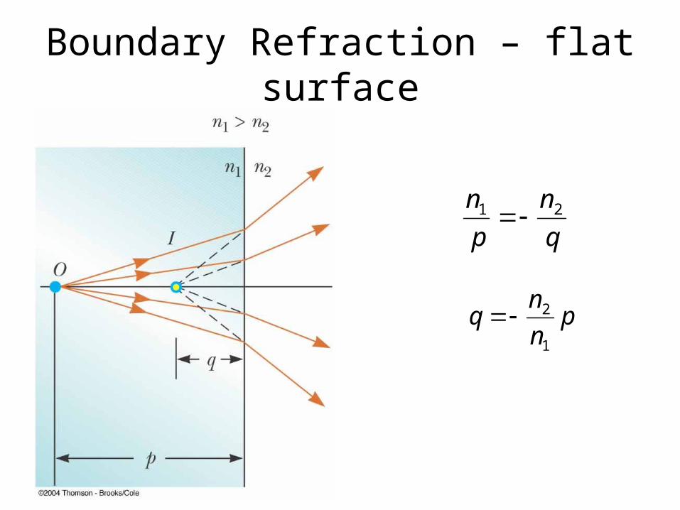
Boundary Refraction – flat surface
q
n
p
n 21
pn
nq
1
2

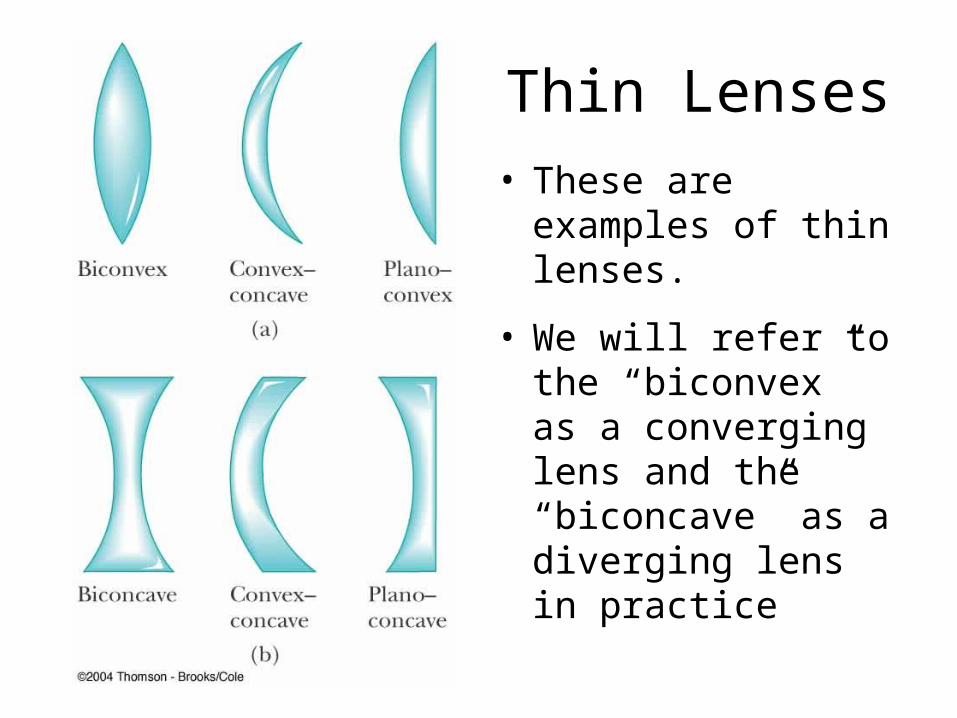
Thin Lenses• These are examples
of thin lenses.
• We will refer to the “biconvex” as a converging lens and the “biconcave” as a diverging lens in practice

21
111
1
RRn
f
• If the radius is different on each side of the lens, a special equation is used.
• This is called the Lens Maker Equation.
• The ‘n’ in the equation represents the index of refraction of the lens glass.
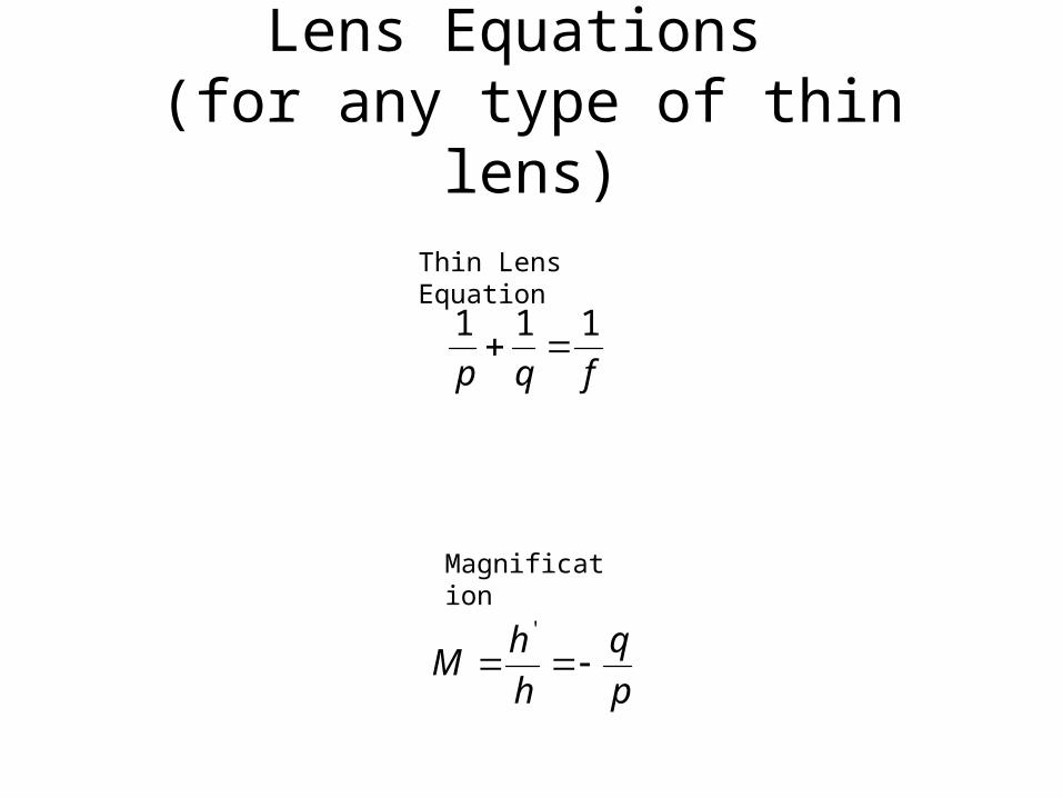
Lens Equations (for any type of thin lens)
Thin Lens Equation
fqp
111
p
q
h
hM
'
Magnification
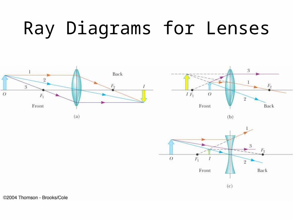
Ray Diagrams for Lenses
Combinations of Thin Lenses
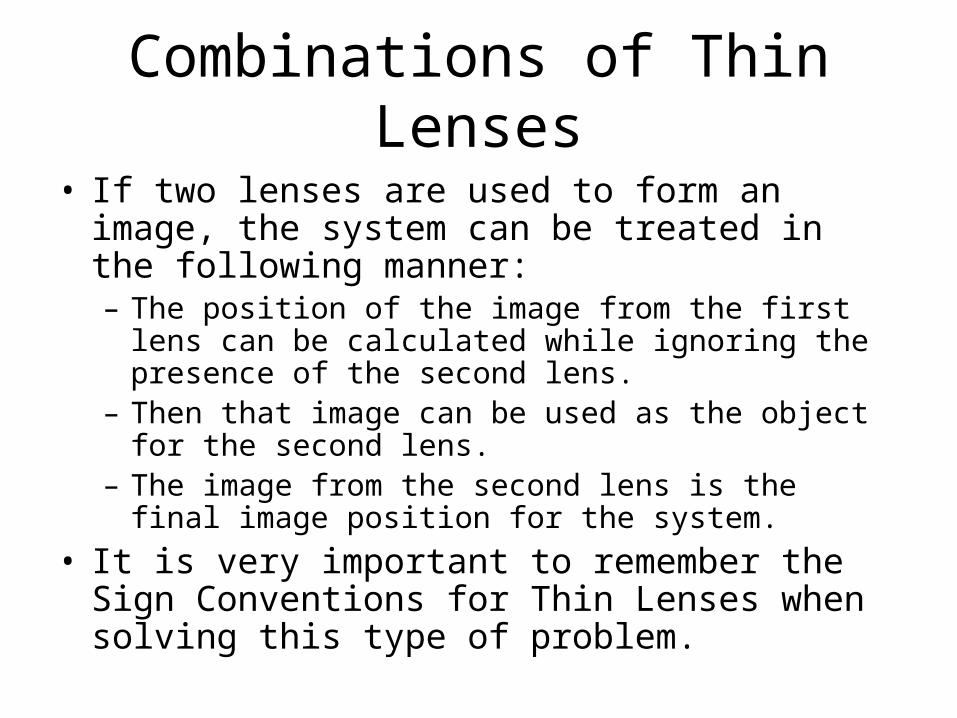
• If two lenses are used to form an image, the system can be treated in the following manner:– The position of the image from the first lens can be
calculated while ignoring the presence of the second lens.
– Then that image can be used as the object for the second lens.
– The image from the second lens is the final image position for the system.
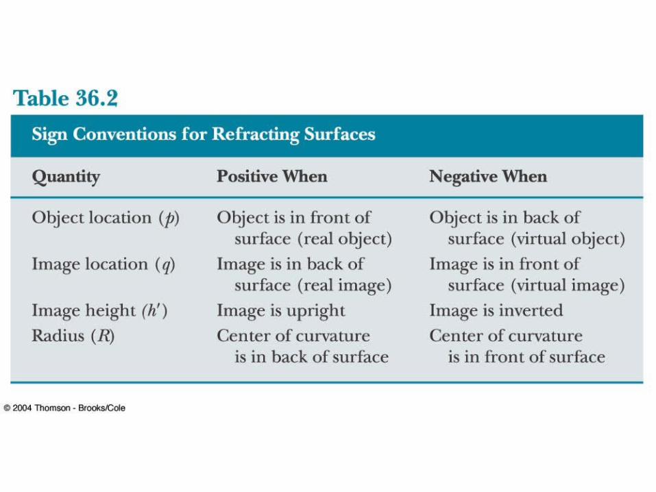
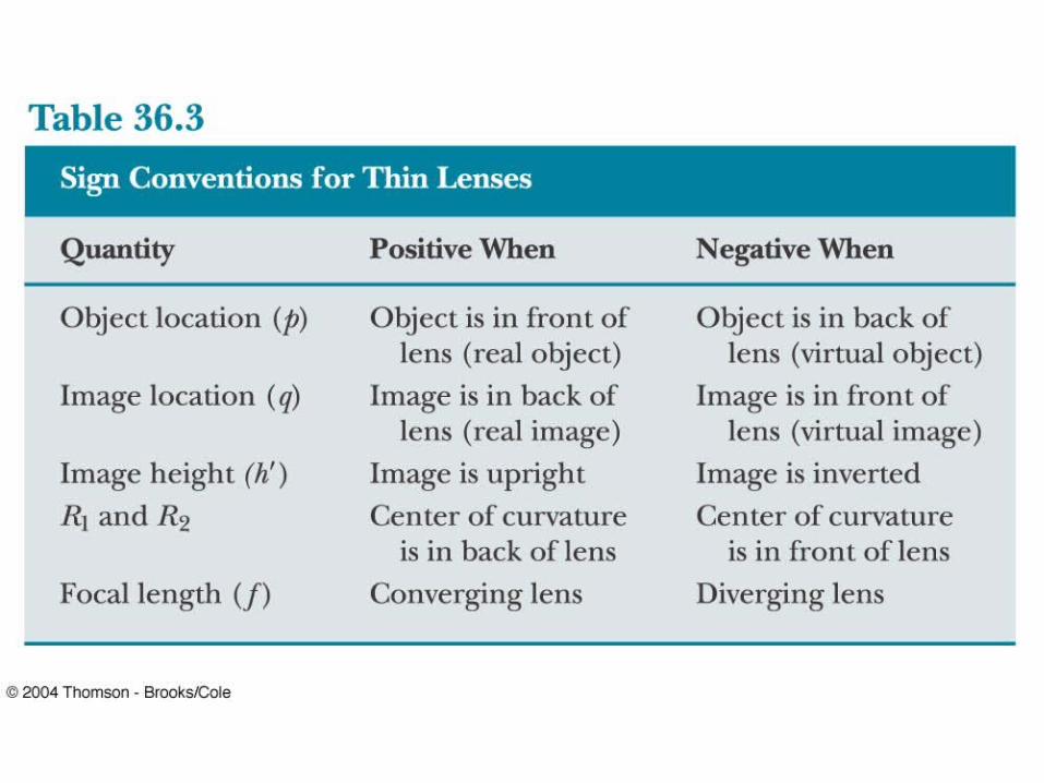
• It is very important to remember the Sign Conventions for Thin Lenses when solving this type of problem.
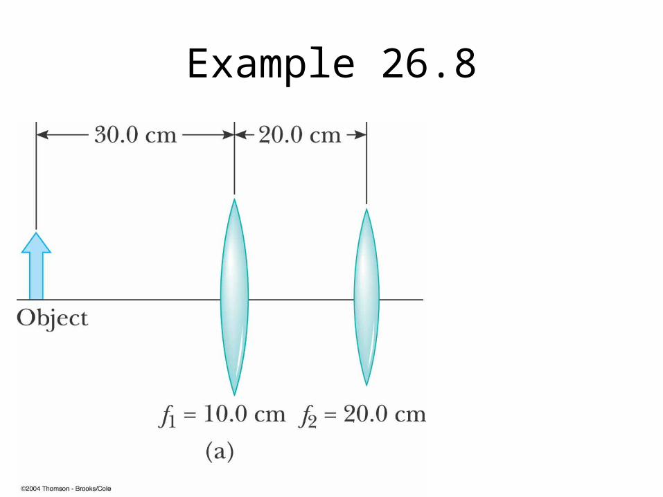
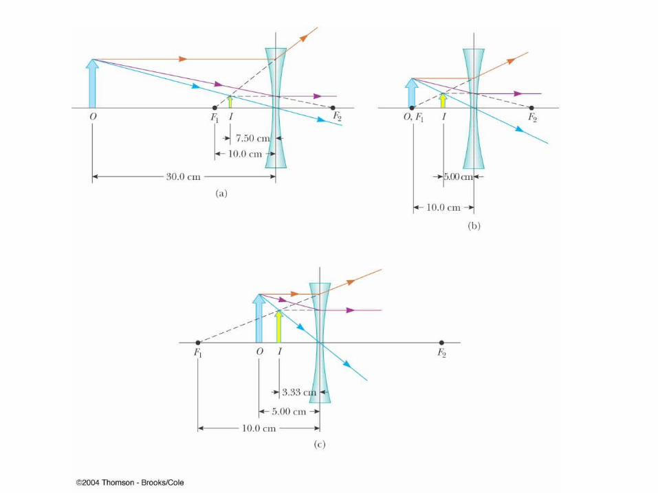
Example 26.8