Embed Size (px)
Citation preview
First Year: Geometrical Optics 0
© Asst. Prof. Dr. Suha Mousa Alawsi 2017
Contents
Dr. Suha Mousa Alawsi
Geometrical Optics
First Year
Reflection and Refraction
Prism
Mirrors
Lenses
Optical Aberration
First Year: Geometrical Optics 1
© Asst. Prof. Dr. Suha Mousa Alawsi 2017
Course Title: Geometrical Optics
Optics is the cornerstone of photonics systems and applications. In this
module, you will learn about one of the two main divisions of basic
optics—geometrical (ray) optics. In 1the module to follow, you will learn
about the other—physical (wave) optics. Geometrical optics will help you
understand the basics of light reflection and refraction and the use of
simple optical elements such as mirrors, prisms, lenses, and fibers.
Physical optics will help you understand the phenomena of light wave
interference, diffraction, and polarization; the use of thin film coatings on
mirrors to enhance or suppress reflection; and the operation of such
devices as gratings and quarter-wave plates.

First Year: Geometrical Optics 2
© Asst. Prof. Dr. Suha Mousa Alawsi 2017
CHAPTER ONE
REFLECTION AND REFRACTION
THE LAWS OF REFLECTION AND REFRACTION
We begin our study of basic geometrical optics by examining how light
reflects and refracts at smooth, plane interfaces. Figure 1-1a shows
ordinary reflection of light at a plane surface, and Figure 1-1b shows
refraction of light at two successive plane surfaces. In each instance, light
is pictured simply in terms of straight lines, which we refer to as light
rays.
Figure 1-1 Light rays undergoing reflection and refraction at plane
surfaces
After a study of how light reflects and refracts at plane surfaces, we
extend our analysis to smooth, curved surfaces, thereby setting the stage
for light interaction with mirrors and lenses the basic elements in many
optical systems
Reflection of light from optical surfaces When light is incident on an
interface between two transparent optical media—such as between air
First Year: Geometrical Optics 3
© Asst. Prof. Dr. Suha Mousa Alawsi 2017
and glass or between water and glass—four things can happen to the
incident light.
• It can be partly or totally reflected at the interface.
• It can be scattered in random directions at the interface.
• It can be partly transmitted via refraction at the interface and enter the
second medium.
• It can be partly absorbed in either medium.
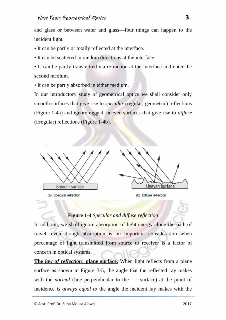
In our introductory study of geometrical optics we shall consider only
smooth surfaces that give rise to specular (regular, geometric) reflections
(Figure 1-4a) and ignore ragged, uneven surfaces that give rise to diffuse
(irregular) reflections (Figure 1-4b).
Figure 1-4 Specular and diffuse reflection
In addition, we shall ignore absorption of light energy along the path of
travel, even though absorption is an important consideration when
percentage of light transmitted from source to receiver is a factor of
concern in optical systems.
The law of reflection: plane surface. When light reflects from a plane
surface as shown in Figure 3-5, the angle that the reflected ray makes
with the normal (line perpendicular to the surface) at the point of
incidence is always equal to the angle the incident ray makes with the

First Year: Geometrical Optics 4
© Asst. Prof. Dr. Suha Mousa Alawsi 2017
same normal. Note carefully that the incident ray, reflected ray, and
normal always lie in the same plane.
Figure -5 Law of reflection: Angle B equals angle A.
The geometry of Figure 1-5 reminds us that reflection of light rays from a
plane, smooth surface is like the geometry of pool shots “banked” along
the wall of a billiard table. With the law of reflection in mind, we can see
that, for the specular reflection shown earlier in Figure 1-4a, each of the
incident, parallel rays reflects off the surface at the same angle, thereby
remaining parallel in reflection as a group. In Figure 1-4b, where the
surface is made up of many small, randomly oriented plane surfaces,
each ray reflects in a direction different from its neighbor, even though
each ray does obey the law of reflection at its own small surface segment.
Reflection from a curved surface. With spherical mirrors, reflection of
light occurs at a curved surface. The law of reflection holds, since at each
point on the curved surface one can draw a surface tangent and erect a
normal to a point P on the surface where the light is incident, as shown
in Figure 1-6. One then applies the law of reflection at point P just as was
illustrated in Figure 1-5, with the incident and reflected rays making the

First Year: Geometrical Optics 5
© Asst. Prof. Dr. Suha Mousa Alawsi 2017
same angles (A and B) with the normal to the surface at P. Note that
successive surface tangents along the curved surface in Figure 1-6 are
ordered (not random) sections of “plane mirrors” and serve—when
smoothly connected—as a spherical surface mirror, capable of forming
distinct images.
Since point P can be moved anywhere along the curved surface and a
normal drawn there, we can always find the direction of the reflected ray
by applying the law of reflection. We shall apply this technique when
studying the way mirrors reflect light from the image.
Figure 1-6 Reflection at a curved surface: Angle B equals angle A
Index of refraction. The two transparent optical media that form an
interface are distinguished from one another by a constant called the
index of refraction, generally labeled with the symbol n. The index of
refraction for any transparent optical medium is defined as the ratio of the
speed of light in a vacuum to the speed of light in the medium, as given in
Equation 1-1

First Year: Geometrical Optics 6
© Asst. Prof. Dr. Suha Mousa Alawsi 2017
where c = speed of light in free space (vacuum)
v = speed of light in the medium
n = index of refraction of the medium
The index of refraction for free space is exactly one. For air and most
gases it is very nearly one, so in most calculations it is taken to be 1.0.
For other materials it has values greater than one. Table 1-1 lists indexes
of refraction for common materials.
Table 1-1 Indexes of Refraction for Various Materials at 589 nm
The greater the index of refraction of a medium, the lower the speed of
light in that medium and the more light is bent in going from air into the
medium. Figure 1-7shows two general cases, one for light passing from a
medium of lower index to higher index, the other from higher index to
lower index. Note that in the first case (lower-to-higher) the light ray is
bent toward the normal. In the second case (higher-to-lower) the light
ray is bent away from the normal. It is helpful to memorize these effects
since they often help one trace light through optical media in a generally
correct manner.

First Year: Geometrical Optics 7
© Asst. Prof. Dr. Suha Mousa Alawsi 2017
Figure 1-7 Refraction at an interface between media of refractive indexes
n1 and n2
Snell’s law. Snell’s law of refraction relates the sines of the angles of
incidence and refraction at an interface between two optical media to the
indexes of refraction of the two media. The law is named after a Dutch
astronomer, Willebrord Snell, who formulated the law in the 17th
century. Snell’s law enables us to calculate the direction of the refracted
ray if we know the refractive indexes of the two media and the direction
of the incident ray. The mathematical expression of Snell’s law and an
accompanying drawing are given in Figure 1-8.
Figure 1-8 Snell’s law: formula and geometry

First Year: Geometrical Optics 8
© Asst. Prof. Dr. Suha Mousa Alawsi 2017
Note carefully that both the angle of incidence (i) and refraction (r) are
measured with respect to the surface normal. Note also that the incident
ray, normal, and refracted ray all lie in the same geometrical plane. In
practice Snell’s law is often written simply as equation 1-2
Now let’s look at an example that make use of Snell’s law.
Example 1
In a handheld optical instrument used under water, light is incident from
water onto the plane
surface of flint glass at an angle of incidence of 45°.
(a) What is the angle of reflection of light off the flint glass?
(b) Does the refracted ray bend toward or away from the normal?
(c) What is the angle of refraction in the flint glass?
Solution:
(a) From the law of reflection, the reflected light must head off at an
angle of 45° with the normal. (Note: The angle of reflection is not
dependent on the refractive indexes of the two media.)
(b) From Table 1-1, the index of refraction is 1.33 for water and 1.63 for
flint glass. Thus, light is moving from a lower to a higher index of
refraction and will bend toward the normal.
We know then that the angle of refraction r should be less than 45°.
(c) From Snell’s law, Equation 3-2, we have:
ni sin i = nr sin r
First Year: Geometrical Optics 9
© Asst. Prof. Dr. Suha Mousa Alawsi 2017
where ni = 1.33, i = 45°, and ni = 1.63
The angle of refraction is about 35°, clearly less than 45°, just as was
predicted in part (b).
Note: The function sin−1 is of course the arcsin. We will use the sin−1
notation since that is what is found on scientific calculators.
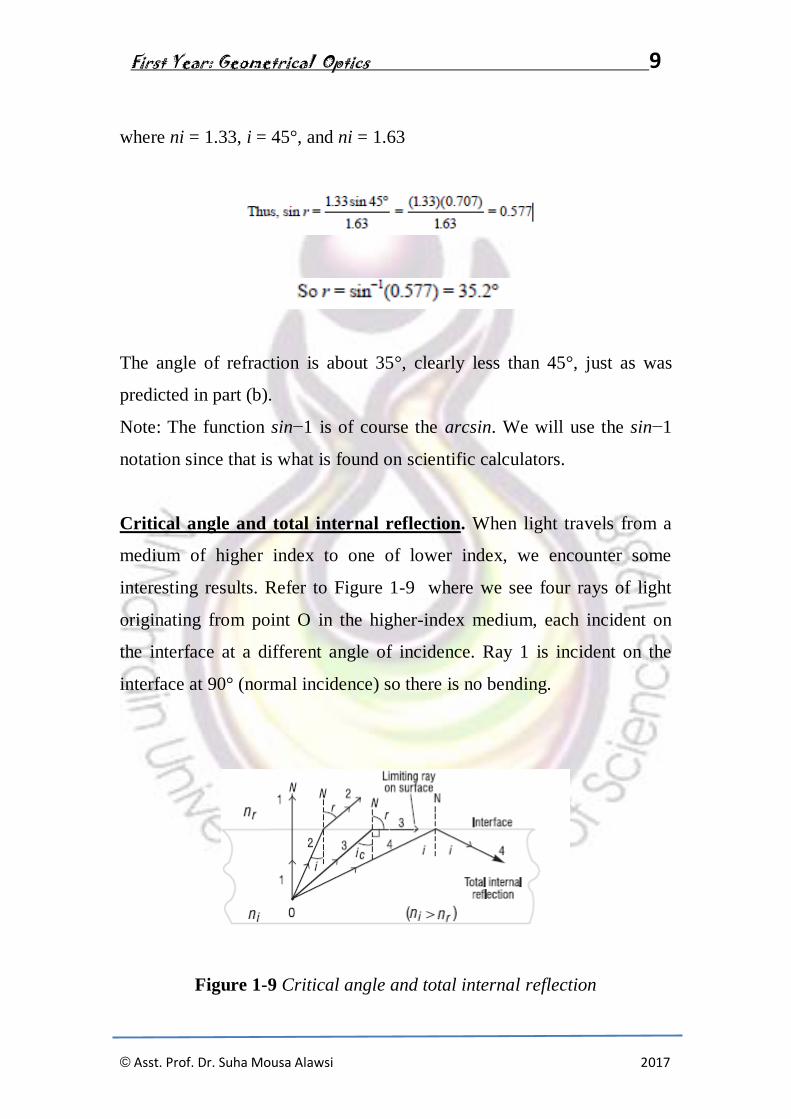
Critical angle and total internal reflection. When light travels from a
medium of higher index to one of lower index, we encounter some
interesting results. Refer to Figure 1-9 where we see four rays of light
originating from point O in the higher-index medium, each incident on
the interface at a different angle of incidence. Ray 1 is incident on the
interface at 90° (normal incidence) so there is no bending.
Figure 1-9 Critical angle and total internal reflection

First Year: Geometrical Optics 10
© Asst. Prof. Dr. Suha Mousa Alawsi 2017
The light in this direction simply speeds up in the second medium (why?)
but continues along the same direction. Ray 2 is incident at angle i and
refracts (bends away from the normal) at angle r. Ray 3 is incident at the
critical angle ic, large enough to cause the refracted ray bending away
from the normal (N) to bend by 90°, thereby traveling along the interface
between the two media. (This ray is trapped in the interface.) Ray 4 is
incident on the interface at an angle greater than the critical angle, and is
totally reflected into the same medium from which it came. Ray 4 obeys
the law of reflection so that its angle of reflection is exactly equal to its
angle of incidence. We exploit the phenomenon of total internal reflection
when designing light propagation in fibers by trapping the light in the
fiber through successive internal reflections along the fiber. We do this
also when designing “retroreflecting” prisms. Compared with ordinary
reflection from mirrors, the sharpness and brightness of totally internally
reflected light beams is enhanced considerably.
The calculation of the critical angle of incidence for any two optical
media—whenever light is incident from the medium of higher index—is
accomplished with Snell’s law. Referring to Ray 3 in Figure 3-10 and
using Snell’s law in Equation 3-2 appropriately, we have
ni sin ic = nr sin 90°
here ni is the index for the incident medium, ic is the critical angle of
incidence, nr is the index for the medium of lower index, and r = 90° is
the angle of refraction at the critical angle. Then, since sin 90° = 1, we
obtain for the critical angle, equation 1-3
First Year: Geometrical Optics 11
© Asst. Prof. Dr. Suha Mousa Alawsi 2017
Let’s use this result and Snell’s law to determine the entrance cone for
light rays incident on the face of a clad fiber if the light is to be trapped
by total internal reflection at the core-cladding
interface in the fiber.
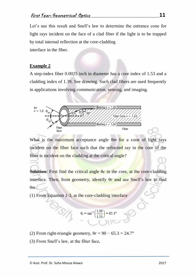
Example 2
A step-index fiber 0.0025 inch in diameter has a core index of 1.53 and a
cladding index of 1.39. See drawing. Such clad fibers are used frequently
in applications involving communication, sensing, and imaging.
What is the maximum acceptance angle θm for a cone of light rays
incident on the fiber face such that the refracted ray in the core of the
fiber is incident on the cladding at the critical angle?
Solution: First find the critical angle θc in the core, at the core-cladding
interface. Then, from geometry, identify θr and use Snell’s law to find
θm.
(1) From Equation 1-3, at the core-cladding interface
(2) From right-triangle geometry, θr = 90 − 65.3 = 24.7°
(3) From Snell’s law, at the fiber face,

First Year: Geometrical Optics 12
© Asst. Prof. Dr. Suha Mousa Alawsi 2017
Thus, the maximum acceptance angle is 39.7° and the acceptance cone is
twice that, or 2 θm = 79.4°.The acceptance cone indicates that any light
ray incident on the fiber face within the acceptance angle will undergo
total internal reflection at the core-cladding face and remain trapped in
the fiber.

First Year: Geometrical Optics 13
© Asst. Prof. Dr. Suha Mousa Alawsi 2017
CHAPTER TWO
PRISM
Refraction in prisms
Glass prisms are often used to bend light in a given direction as well as to
bend it back again (retroreflection). The process of refraction in prisms is
understood easily with the use of light rays and Snell’s law. Look at
Figure 1-10a. When a light ray enters a prism at one face and exits at
another, the exiting ray is deviated from its original direction. The prism
shown is isosceles in cross section with apex angle A = 30° and
refractive index n = 1.50. The incident angle θ and the angle of deviation
δ are shown on the diagram.
Figure 1-10b shows how the angle of deviation δ changes as the angle θ
of the incident ray changes. The specific curve shown is for the prism
described in Figure 3-11a. Note that δ goes through a minimum value,
about 23° for this specific prism. Each prism material has its own unique
minimum angle of deviation.
Figure 1-10 Refraction of light through a prism

First Year: Geometrical Optics 14
© Asst. Prof. Dr. Suha Mousa Alawsi 2017
Minimum angle of deviation. It turns out that we can determine the
refractive index of a transparent material by shaping it in the form of an
isosceles prism and then measuring its minimum angle of deviation. With
reference to Figure 1-10a, the relationship between the refractive index n,
the prism apex angle A, and the minimum angle of deviation δm is given
by equation 1-4
where both A and δm are measured in degrees.
The derivation of Equation 1-4 is straightforward, but a bit tedious.
Details of the derivation making use of Snell’s law and geometric
relations between angles at each refracting surface can be found in most
standard texts on geometrical optics. (See suggested references at the end
of the module.) Let’s show how one can use Equation 3-4 in Example 4
to determine the index of refraction of an unknown glass shaped in the
form of a prism
Example 3
A glass of unknown index of refraction is shaped in the form of an
isosceles prism with an apex angle of 25°. In the laboratory, with the help
of a laser beam and a prism table, the minimum angle of deviation for
this prism is measured carefully to be 15.8°. What is the refractive index
of this glass material?
First Year: Geometrical Optics 15
© Asst. Prof. Dr. Suha Mousa Alawsi 2017
Solution: Given that δm = 15.8° and A = 25°, we use Equation 3-4 to
calculate the refractive index.
Dispersion of light.
Table 1-1 lists indexes of refraction for various substances independent
of the wavelength of the light. In fact, the refractive index is slightly
wavelength dependent. For example, the index of refraction for flint glass
is about 1% higher for blue light than for red light. The variation of
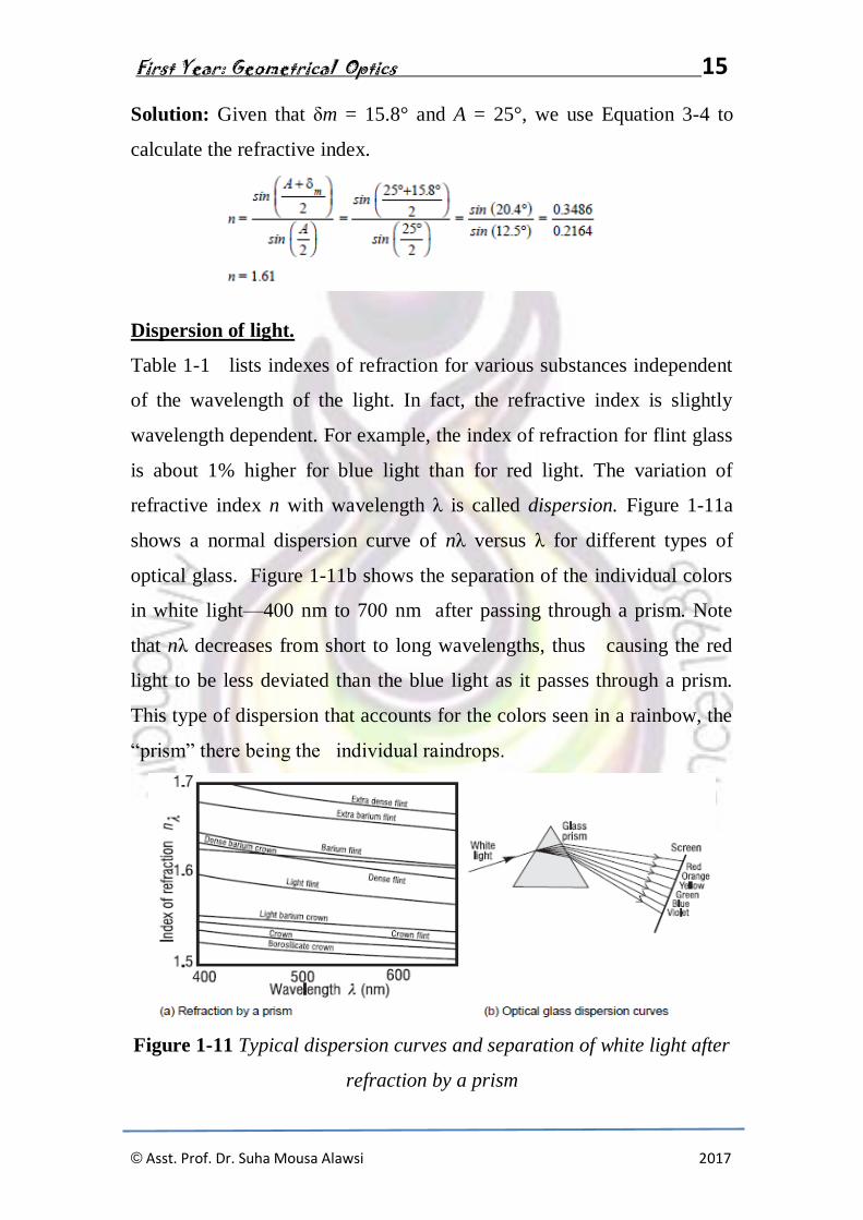
refractive index n with wavelength λ is called dispersion. Figure 1-11a
shows a normal dispersion curve of nλ versus λ for different types of
optical glass. Figure 1-11b shows the separation of the individual colors
in white light—400 nm to 700 nm after passing through a prism. Note
that nλ decreases from short to long wavelengths, thus causing the red
light to be less deviated than the blue light as it passes through a prism.
This type of dispersion that accounts for the colors seen in a rainbow, the
“prism” there being the individual raindrops.
Figure 1-11 Typical dispersion curves and separation of white light after
refraction by a prism

First Year: Geometrical Optics 16
© Asst. Prof. Dr. Suha Mousa Alawsi 2017
CHAPTER THREE
MIRRORS
IMAGE FORMATION WITH MIRRORS
Mirrors, of course, are everywhere—in homes, auto headlamps,
astronomical telescopes, and laser cavities, and many other places. Plane
and spherical mirrors are used to form three dimensional images of
three-dimensional objects. If the size, orientation, and location of an
object relative to a mirror are known, the law of reflection and ray tracing
can be used to locate the image graphically. Appropriate mathematical
formulas can also be used to calculate the locations and sizes of the
images formed by mirrors. In this section we shall use both graphical ray
tracing and formulas.
plane mirrors
Images with mirrors are formed when many nonparallel rays from a given
point on a source are reflected from the mirror surface, converge, and
form a corresponding image point. When this happens, point by point for
an extended object, an image of the object, point by point, is formed.
Image formation in a plane mirror is illustrated in several sketches shown
in Figure 2-1

First Year: Geometrical Optics 17
© Asst. Prof. Dr. Suha Mousa Alawsi 2017
Figure 2-1 Image formation in a plane mirror
In Figure 2-1a, point object S sends nonparallel rays toward a plane
mirror, which reflects them as shown. The law of reflection ensures that
pairs of triangles like SNP and S′NP are equal, so that all reflected rays
appear to originate at the image point S′, which lies along the normal line
SN, and at such depth that the image distance S′N equals the object
distance SN.
The eye sees a point image at S′ in exactly the same way it would see a
real point object placed there. Since the actual rays do not exist below the
mirror surface, the image is said to be a virtual image. The image S′
cannot be projected on a screen as in the case of a real image. An
extended object, such as the arrow in Figure 3-14b, is imaged point by
point by a plane mirror surface in similar fashion. Each object point has
its image point along its normal to the mirror surface and as far below the
reflecting surface as the object point lies above the surface. Note that
image position does not depend on the position of the eye.

First Year: Geometrical Optics 18
© Asst. Prof. Dr. Suha Mousa Alawsi 2017
The construction in Figure 2-1b also makes clear that the image size is
identical to the object size, giving a magnification of unity. In addition,
the transverse orientations of object and image are the same. A right-
handed object, however, appears left-handed in its image. In Figure 2-1c,
where the mirror does not lie directly below the object, the mirror plane
may be extended to determine the position of the image as seen by an eye
positioned to receive reflected rays originating at the object. Figure 2-1d
illustrates multiple images of a point object O formed by two
perpendicular mirrors. Each image, I and I2, results from a single
reflection in one of the two mirrors, but a third image I3 is also present,
formed by sequential reflections from both mirrors.
spherical mirrors
The law of reflection can be used to determine the direction along which
any ray incident on a spherical mirror surface will be reflected. Using the
law of reflection, we can trace rays from any point on an object to the
mirror, and from there on to the corresponding image point. This is the
method of graphical ray tracing.
Graphical ray-trace method. To employ the method of ray tracing, we
agree on the following:
• Light will be incident on a mirror surface initially from the left.
• The axis of symmetry normal to the mirror surface is its optical axis.
• The point where the optical axis meets the mirror surface is the vertex.
To locate an image we use two points common to each mirror surface, the
center of curvature C and the focal point F. They are shown in Figure 2-
2, with the mirror vertex V, for both a concave and a convex spherical
mirror.
First Year: Geometrical Optics 19
© Asst. Prof. Dr. Suha Mousa Alawsi 2017
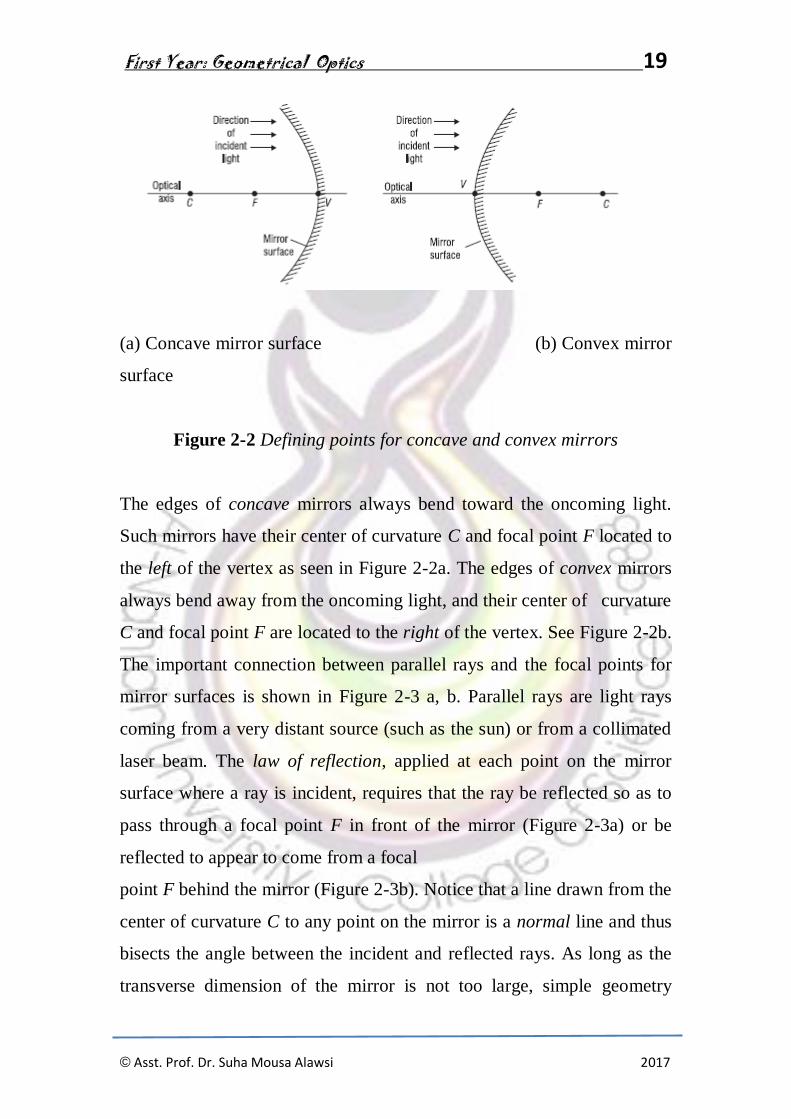
(a) Concave mirror surface (b) Convex mirror
surface
Figure 2-2 Defining points for concave and convex mirrors
The edges of concave mirrors always bend toward the oncoming light.
Such mirrors have their center of curvature C and focal point F located to
the left of the vertex as seen in Figure 2-2a. The edges of convex mirrors
always bend away from the oncoming light, and their center of curvature
C and focal point F are located to the right of the vertex. See Figure 2-2b.
The important connection between parallel rays and the focal points for
mirror surfaces is shown in Figure 2-3 a, b. Parallel rays are light rays
coming from a very distant source (such as the sun) or from a collimated
laser beam. The law of reflection, applied at each point on the mirror
surface where a ray is incident, requires that the ray be reflected so as to
pass through a focal point F in front of the mirror (Figure 2-3a) or be
reflected to appear to come from a focal
point F behind the mirror (Figure 2-3b). Notice that a line drawn from the
center of curvature C to any point on the mirror is a normal line and thus
bisects the angle between the incident and reflected rays. As long as the
transverse dimension of the mirror is not too large, simple geometry

First Year: Geometrical Optics 20
© Asst. Prof. Dr. Suha Mousa Alawsi 2017
shows that the point F, for either mirror, is located at the midpoint
between C and F, so that the distance FV is one-half the radius of
curvature CV. The distance FV is called the focal length and is commonly
labeled as f.
Figure 2-3 Parallel rays and focal points
Derivation of the mirror formula. The drawing we need to carry out the
derivation is shown in Figure 2-4. The important quantities are the object
distance p, the image distance q, and the radius of curvature r. Both p and
q are measured relative to the mirror vertex, as shown, and the sign on r
will indicate whether the mirror is concave or convex. All other quantities
in Figure 2-4 are used in the derivation but will not show up in the final
“mirror formula
Figure 2-4 Basic drawing for deriving the mirror formula

First Year: Geometrical Optics 21
© Asst. Prof. Dr. Suha Mousa Alawsi 2017
The mirror shown in Figure 2-4 is convex with center of curvature C on
the right. Two rays of light originating at object point O are drawn, one
normal to the convex surface at its vertex V and the other an arbitrary ray
incident at P. The first ray reflects back along itself; the second reflects at
P as if incident on a plane tangent at P, according to the law of reflection.
Relative to each other, the two reflected rays diverge as they leave the
mirror. The intersection of the two rays (extended backward) determines
the image point I corresponding to object point O. The image is virtual
and located behind the mirror surface. Object and image distances
measured from the vertex V are shown as p and q, respectively. A
perpendicular of height h is drawn from P to the axis at Q. We seek a
relationship between p and q that depends on only the radius of curvature
r of the mirror. As we shall see, such a relation is possible only to a first-
order approximation of the sines and cosines of angles such as α and ϕ
made by the object and image rays at various points on the spherical
surface. This means that, in place of expansions of sin ϕ and cos ϕ in
series as shown here,
we consider the first terms only and write
sin ϕ ≅ ϕ and cos ϕ ≅ 1, so that tan ϕ = sin ϕ/cos ϕ= ϕ
These relations are accurate to 1% or less if the angle ϕ is 10° or smaller.
This approximation leads to first-order (or Gaussian) optics, after Karl
Friedrich Gauss, who in 1841 developed the foundations of this subject.

First Year: Geometrical Optics 22
© Asst. Prof. Dr. Suha Mousa Alawsi 2017
Returning now to the problem at hand—that of relating p, q, and r notice
that two angular relationships may be obtained from Figure 2-4, because
the exterior angle of a triangle equals the sum of its interior angles. Thus,
θ = α + ϕ in ΔOPC and 2θ = α + α′ in ΔOPI
which combine to give
α − α′ = 2ϕ
Using the small-angle approximation, the angles α, α′, and ϕ above can
be replaced by their tangents, yielding
Note that we have neglected the axial distance VQ, small when ϕ is
small. Cancellation of h produces the desired relationship, equation (2-1)
If the spherical surface is chosen to be concave instead, the center of
curvature will be to the left. For certain positions of the object point O, it
is then possible to find a real image point, also to the left of the mirror. In
these cases, the resulting geometric relationship analogous to Equation
(2-1) consists of the same terms, but with different algebraic signs,
depending on the sign convention employed. We can choose a sign
convention that leads to a single equation, the mirror equation, valid for
both types of mirrors. It is Equation (2-2)
First Year: Geometrical Optics 23
© Asst. Prof. Dr. Suha Mousa Alawsi 2017
Sign convention.
The sign convention to be used in conjunction with Equation 3-6 and
Figure2-4 is as follows.
• Object and image distances p and q are both positive when located to
the left of the
vertex and both negative when located to the right.
• The radius of curvature r is positive when the center of curvature C is to
the left of the vertex (concave mirror surface) and negative when C is to
the right (convex mirror surface).
• Vertical dimensions are positive above the optical axis and negative
below.
In the application of these rules, light is assumed to be directed initially,
as we mentioned earlier, from left to right According to this sign
convention, positive object and image distances correspond to real
objects and images, and negative object and image distances correspond
to virtual objects and images. Virtual objects occur only with a sequence
of two or more reflecting or refracting elements.
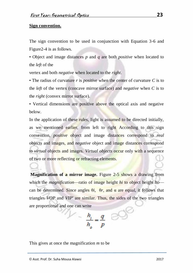
Magnification of a mirror image. Figure 2-5 shows a drawing from
which the magnification—ratio of image height hi to object height ho—
can be determined. Since angles θi, θr, and α are equal, it follows that
triangles VOP and VIP′ are similar. Thus, the sides of the two triangles
are proportional and one can write
This gives at once the magnification m to be

First Year: Geometrical Optics 24
© Asst. Prof. Dr. Suha Mousa Alawsi 2017
When the sign convention is taken into account, one has, for the general
case, a single equation, Equation 2-3, valid for both convex and concave
mirrors.
If, after calculation, the value of m is positive, the image is erect. If the
value is negative, the image is inverted.
Figure 2-5 Construction for derivation of mirror magnification formula

First Year: Geometrical Optics 25
© Asst. Prof. Dr. Suha Mousa Alawsi 2017
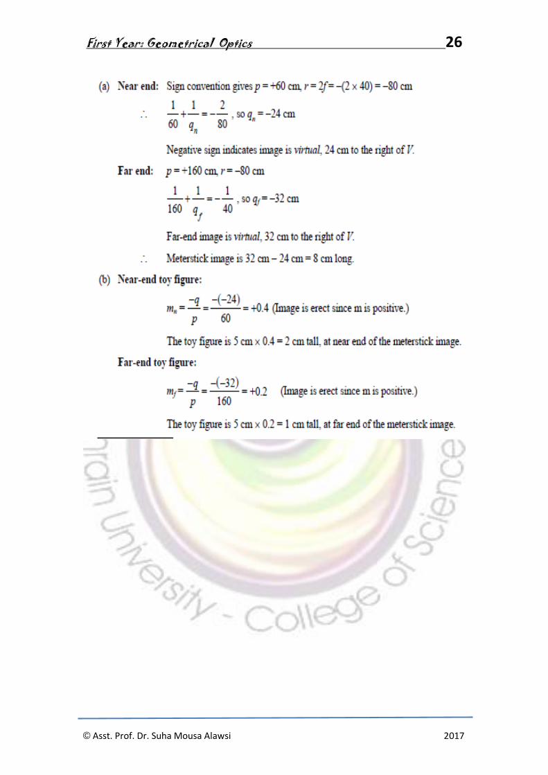
Example 1
A meter stick lies along the optical axis of a convex mirror of focal length
40 cm, with its near end 60 cm from the mirror surface. Five-centimeter
toy figures stand erect on both the near and far ends of the meter stick. (a)
How long is the virtual image of the meter stick? (b) How tall are the toy
figures in the image, and are they erect or inverted?
Solution: Use the mirror equation
twice, once for the near end and once for the far end of the meterstick.
Use the magnification equation m for each figure
First Year: Geometrical Optics 26
© Asst. Prof. Dr. Suha Mousa Alawsi 2017

First Year: Geometrical Optics 27
© Asst. Prof. Dr. Suha Mousa Alawsi 2017
CHAPTER FOUR
LENSES
IMAGE FORMATION WITH LENSES
Lenses are at the heart of many optical devices, not the least of which are
cameras, microscopes, binoculars, and telescopes. Just as the law of
reflection determines the imaging properties of mirrors, so Snell’s law of
refraction determines the imaging properties of lenses. Lenses are
essentially light-controlling elements, used primarily for image formation
with visible light, but also for ultraviolet and infrared light. In this section
we shall look first at the types and properties of lenses, then use graphical
ray-tracing techniques to locate images, and finally use mathematical
formulas to locate the size, orientation, and position of images in simple
lens systems.
A. Function of a lens
A lens is made up of a transparent refracting medium, generally of some
type of glass, with spherically shaped surfaces on the front and back. A
ray incident on the lens refracts at the front surface (according to Snell’s
law) propagates through the lens, and refracts again at the rear surface.
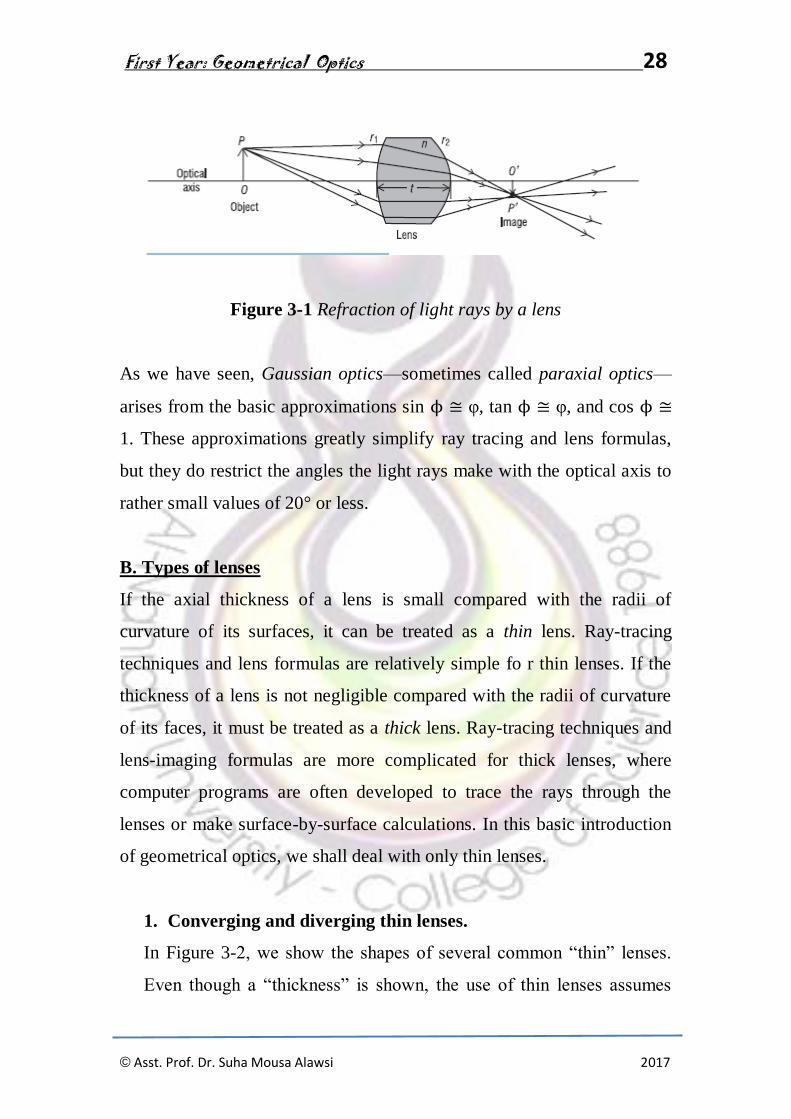
Figure 3-1 shows a rather thick lens refracting rays from an object OP to
form an image O′P′. The ray-tracing techniques and lens formulas we
shall use here are based again on Gaussian optics, just as they were for
mirrors.
First Year: Geometrical Optics 28
© Asst. Prof. Dr. Suha Mousa Alawsi 2017
Figure 3-1 Refraction of light rays by a lens
As we have seen, Gaussian optics—sometimes called paraxial optics—
arises from the basic approximations sin ϕ ≅ φ, tan ϕ ≅ φ, and cos ϕ ≅
1. These approximations greatly simplify ray tracing and lens formulas,
but they do restrict the angles the light rays make with the optical axis to
rather small values of 20° or less.
B. Types of lenses
If the axial thickness of a lens is small compared with the radii of
curvature of its surfaces, it can be treated as a thin lens. Ray-tracing
techniques and lens formulas are relatively simple fo r thin lenses. If the
thickness of a lens is not negligible compared with the radii of curvature
of its faces, it must be treated as a thick lens. Ray-tracing techniques and
lens-imaging formulas are more complicated for thick lenses, where
computer programs are often developed to trace the rays through the
lenses or make surface-by-surface calculations. In this basic introduction
of geometrical optics, we shall deal with only thin lenses.
1. Converging and diverging thin lenses.
In Figure 3-2, we show the shapes of several common “thin” lenses.
Even though a “thickness” is shown, the use of thin lenses assumes

First Year: Geometrical Optics 29
© Asst. Prof. Dr. Suha Mousa Alawsi 2017
that the rays simply refract at the front and rear faces without a
translation through the lens medium. The first three lenses are thicker
in the middle than at the edges and are described as converging or
positive lenses. They are converging because they cause parallel rays
passing through them to bend toward one another. Such lenses give
rise to positive focal lengths. The last three lenses thinner in the
middle than at the edges and are described as diverging or negative
lenses. In contrast with converging lenses, they cause parallel rays
passing through them to spread as they leave the lens. These lenses
give rise to negative focal lengths. In Figure 3-2, names associated
with the different shapes are noted.
Figure 3-2 Shapes of common thin lenses
2- Focal points of thin lenses.
Just as for mirrors, the focal points of lenses are defined in terms of their
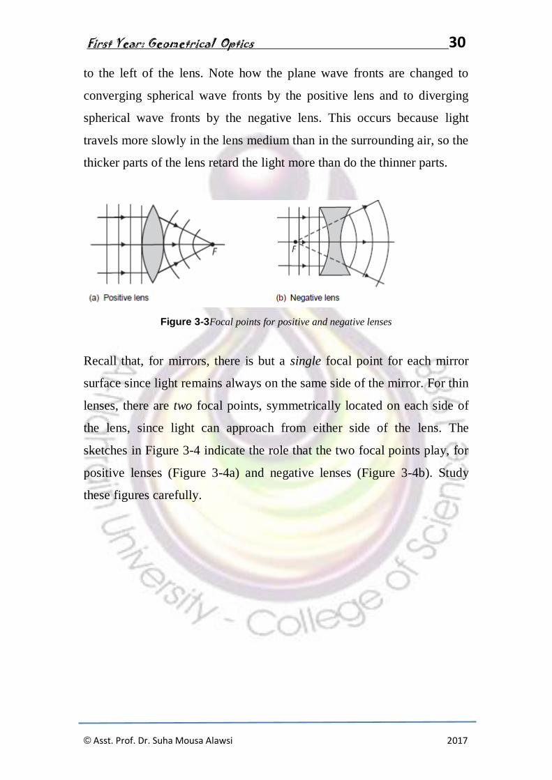
effect on parallel light rays and plane wave fronts. Figure 3-22 shows
parallel light rays and their associated plane wave fronts incident on a
positive lens (Figure 3-3a) and a negative lens (Figure 3-3b). For the
positive lens, refraction of the light brings it to focal point F (real image)
to the right of the lens. For the negative lens, refraction of the light causes
it to diverge as if it is coming from focal point F (virtual image) located
First Year: Geometrical Optics 30
© Asst. Prof. Dr. Suha Mousa Alawsi 2017
to the left of the lens. Note how the plane wave fronts are changed to
converging spherical wave fronts by the positive lens and to diverging
spherical wave fronts by the negative lens. This occurs because light
travels more slowly in the lens medium than in the surrounding air, so the
thicker parts of the lens retard the light more than do the thinner parts.
Figure 3-3Focal points for positive and negative lenses
Recall that, for mirrors, there is but a single focal point for each mirror
surface since light remains always on the same side of the mirror. For thin
lenses, there are two focal points, symmetrically located on each side of
the lens, since light can approach from either side of the lens. The
sketches in Figure 3-4 indicate the role that the two focal points play, for
positive lenses (Figure 3-4a) and negative lenses (Figure 3-4b). Study
these figures carefully.

First Year: Geometrical Optics 31
© Asst. Prof. Dr. Suha Mousa Alawsi 2017
Figure 3-4 Relationship of light rays to right and left focal points in thin
lenses
3- f-number and numerical aperture of a lens.
The size of a lens determines its light gathering power and, consequently,
the brightness of the image it forms. Two commonly used indicators of
this special characteristic of a lens are called the f-number and the
numerical aperture. The f-number, also referred to as the relative
aperture and the f/stop, is defined simply as the ratio of the focal length f
of the lens, to its diameter D, as given in Equation 3-1.
f-number = f/D
In addition, the numerical aperture is closely related to the acceptance
angle discussed Since the rays entering the fiber face are in air, the
numerical aperture N.A. is equal simply to equation 3-2
N.A. = sin α.
It is shown in most basic books on optics (see references listed at end of
this module) that image brightness is dependent on values of the f-number

First Year: Geometrical Optics 32
© Asst. Prof. Dr. Suha Mousa Alawsi 2017
or numerical aperture, in accordance with the following proportionalities:
equation 3-3
image brightness ∝ 1/( f-number)2
image brightness ∝ (N.A.)2
In summary, one can increase the light-gathering power of a lens and the
brightness of the image formed by a lens by decreasing the f-number of
the lens (increasing lens diameter) or by increasing the numerical
aperture of the lens (increasing the refraction index and thus making
possible a larger acceptance angle).
C. Image location by ray tracing
To locate the image of an object formed by a thin lens, we make use of
three key points for the lens and associate each of them with a defining
ray. The three points are the left focal point F, the right focal point F′, and
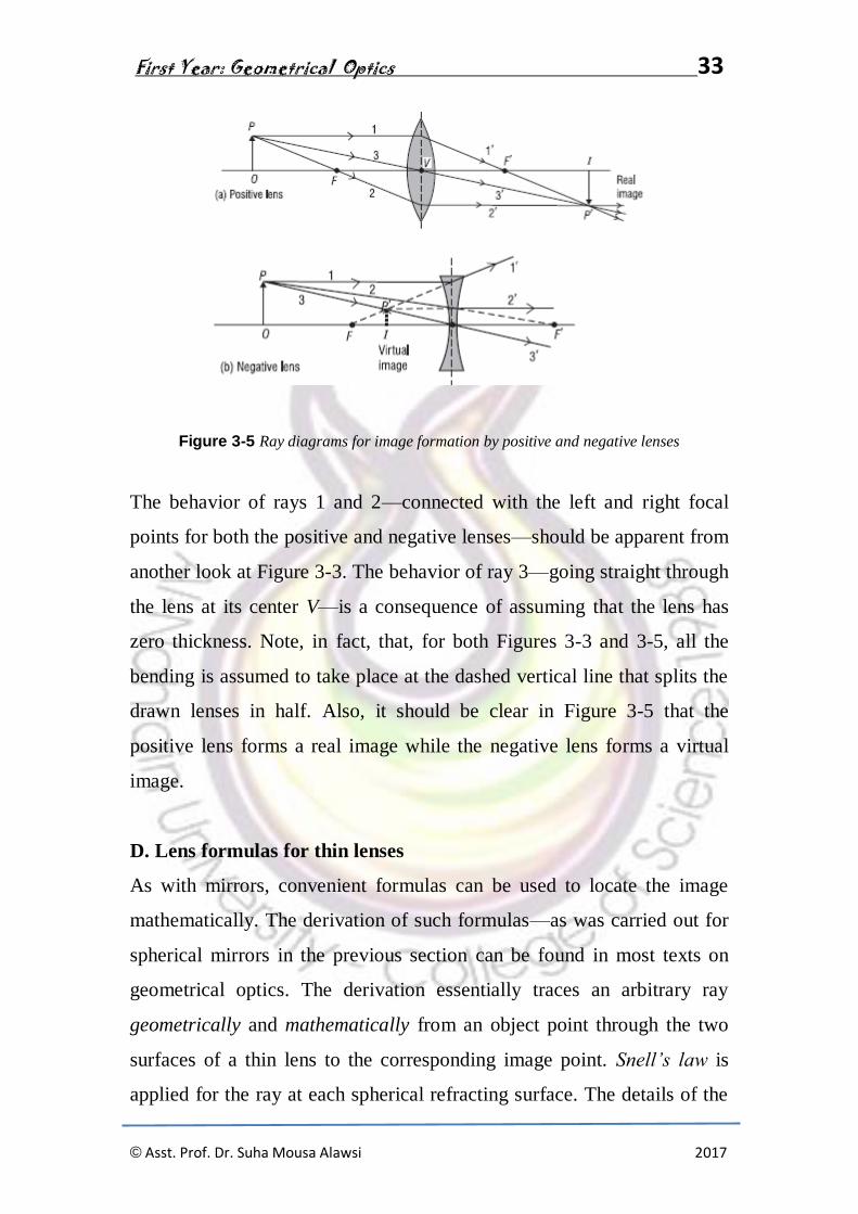
the lens vertex (center) V. In Figure 3-5 the three rays are shown locating
an image point P′ corresponding to a given object point P, for both a
positive and a negative lens. The object is labeled OP and the
corresponding image IP′. The defining rays are labeled to show clearly
their connection to the points F, F′, and V. In practice, of course, only
two of the three rays are needed to locate the desired image point. Note
also that the location of image point P′ is generally sufficient to sketch in
the rest of the image IP′, to correspond with the given object OP.
First Year: Geometrical Optics 33
© Asst. Prof. Dr. Suha Mousa Alawsi 2017
Figure 3-5 Ray diagrams for image formation by positive and negative lenses
The behavior of rays 1 and 2—connected with the left and right focal
points for both the positive and negative lenses—should be apparent from
another look at Figure 3-3. The behavior of ray 3—going straight through
the lens at its center V—is a consequence of assuming that the lens has
zero thickness. Note, in fact, that, for both Figures 3-3 and 3-5, all the
bending is assumed to take place at the dashed vertical line that splits the
drawn lenses in half. Also, it should be clear in Figure 3-5 that the
positive lens forms a real image while the negative lens forms a virtual
image.
D. Lens formulas for thin lenses
As with mirrors, convenient formulas can be used to locate the image
mathematically. The derivation of such formulas—as was carried out for
spherical mirrors in the previous section can be found in most texts on
geometrical optics. The derivation essentially traces an arbitrary ray
geometrically and mathematically from an object point through the two
surfaces of a thin lens to the corresponding image point. Snell’s law is
applied for the ray at each spherical refracting surface. The details of the
First Year: Geometrical Optics 34
© Asst. Prof. Dr. Suha Mousa Alawsi 2017
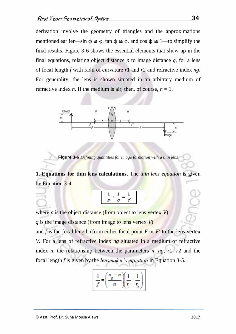
derivation involve the geometry of triangles and the approximations
mentioned earlier—sin ϕ ≅ φ, tan ϕ ≅ φ, and cos ϕ ≅ 1—to simplify the
final results. Figure 3-6 shows the essential elements that show up in the
final equations, relating object distance p to image distance q, for a lens
of focal length f with radii of curvature r1 and r2 and refractive index ng.
For generality, the lens is shown situated in an arbitrary medium of
refractive index n. If the medium is air, then, of course, n = 1.
Figure 3-6 Defining quantities for image formation with a thin lens
1. Equations for thin lens calculations. The thin lens equation is given
by Equation 3-4.
where p is the object distance (from object to lens vertex V)
q is the image distance (from image to lens vertex V)
and f is the focal length (from either focal point F or F′ to the lens vertex
V. For a lens of refractive index ng situated in a medium of refractive
index n, the relationship between the parameters n, ng, r1, r2 and the
focal length f is given by the lensmaker’s equation in Equation 3-5.
First Year: Geometrical Optics 35
© Asst. Prof. Dr. Suha Mousa Alawsi 2017
where n is the index of refraction of the surrounding medium
ng is the index of refraction of the lens materials
r1 is the radius of curvature of the front face of the lens
r2 is the radius of curvature of the rear face of the lens
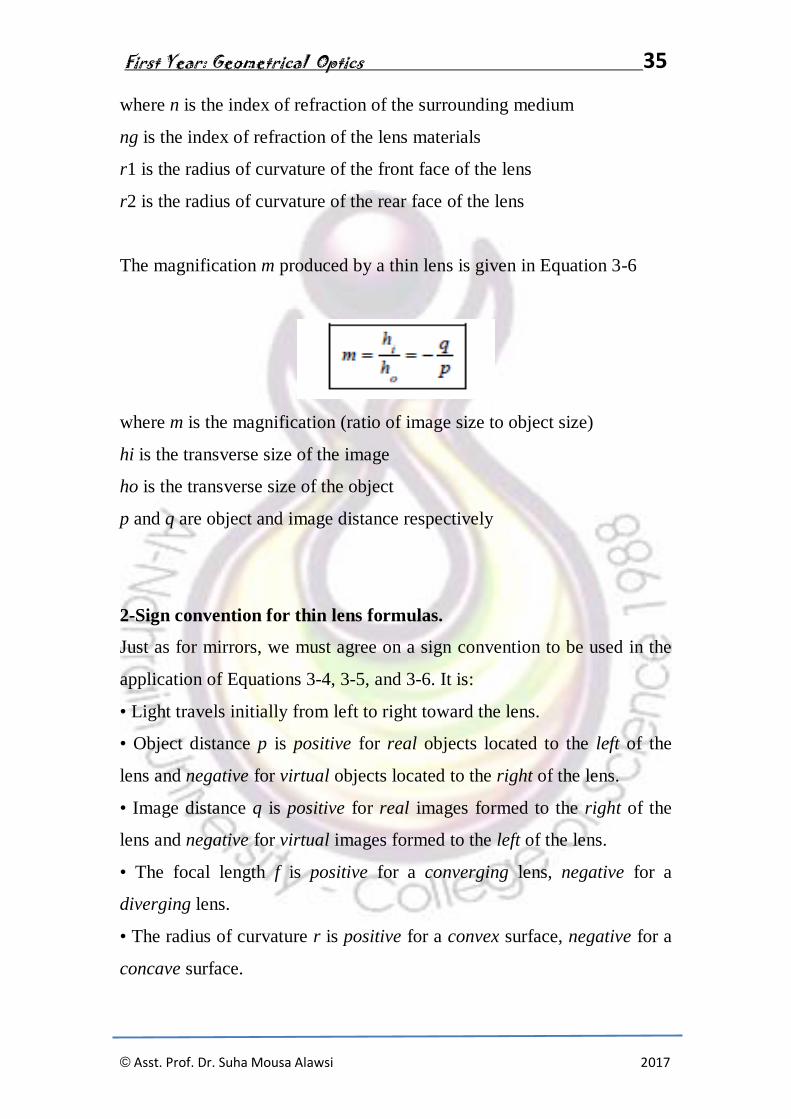
The magnification m produced by a thin lens is given in Equation 3-6
where m is the magnification (ratio of image size to object size)
hi is the transverse size of the image
ho is the transverse size of the object
p and q are object and image distance respectively
2-Sign convention for thin lens formulas.
Just as for mirrors, we must agree on a sign convention to be used in the
application of Equations 3-4, 3-5, and 3-6. It is:
• Light travels initially from left to right toward the lens.
• Object distance p is positive for real objects located to the left of the
lens and negative for virtual objects located to the right of the lens.
• Image distance q is positive for real images formed to the right of the
lens and negative for virtual images formed to the left of the lens.
• The focal length f is positive for a converging lens, negative for a
diverging lens.
• The radius of curvature r is positive for a convex surface, negative for a
concave surface.

First Year: Geometrical Optics 36
© Asst. Prof. Dr. Suha Mousa Alawsi 2017
• Transverse distances (ho and hi) are positive above the optical axis,
negative below.
Now let’s apply Equations 3-4, 3-5, and 3-6 in several examples, where
the use of the sign convention is illustrated and where the size,
orientation, and location of a final image are determined.
Example 1
A double-convex thin lens such as that shown in Figure 3-21 can be used
as a simple “magnifier.” It has a front surface with a radius of curvature
of 20 cm and a rear surface with a radius of curvature of 15 cm. The lens
material has a refractive index of 1.52. Answer the following questions to
learn more about this simple magnifying lens.
(a) What is its focal length in air?
(b) What is its focal length in water (n = 1.33)?
(c) Does it matter which lens face is turned toward the light?
(d) How far would you hold an index card from this lens to form a sharp
image of the sun on
the card?
Solution:
(a) Use the lensmaker’s equation. With the sign convention given, we
have ng = 1.52, n =
1.00, r1 = +20 cm, and r2 = − 15 cm. Then
So f = +16.5 cm (a converging lens, so the sign is positive, as it should
be)

First Year: Geometrical Optics 37
© Asst. Prof. Dr. Suha Mousa Alawsi 2017
f = 60 cm (converging but less so than in air)
(c) No, the magnifying lens behaves the same, having the same focal
length, no matter which surface faces the light. You can prove this by
reversing the lens and repeating the calculation with Equation 3-5.
Results are the same. But note carefully, reversing a thick lens changes
its effect on the light passing through it. The two orientations are not
equivalent.
(d) Since the sun is very far away, its light is collimated (parallel rays) as
it strikes the lens and will come to a focus at the lens focal point. Thus,
one should hold the lens about 16.5 cm from the index card to form a
sharp image on the card.
Example 2
A two-lens system is made up of a converging lens followed by a
diverging lens, each of focal length 15 cm. The system is used to form an
image of a short nail, 1.5 cm high, standing erect, 25 cm from the first
lens. The two lenses are separated by a distance of 60 cm. See
accompanying diagram. Locate the final image, determine its size, and
state whether it is real or virtual, erect or inverted.
Solution: We apply the thin lens equations to each lens in turn, making
use of the correct sign convention at each step.

First Year: Geometrical Optics 38
© Asst. Prof. Dr. Suha Mousa Alawsi 2017
Since the first image, a distance q1 from L1, serves as the object for the
lens L2, this object is to the left of lens L2, and thus its distance p2 is
positive. The focal length for L2 is negative since it is a diverging lens.
So, the thin lens equation becomes
Since q2 is negative, it locates a virtual image, 9 cm to the left of lens L2.
The overall magnification for the two-lens system is given by the
combined magnification of the
lenses. Then
Thus, the final image is inverted (since overall magnification is negative)
and is of final size
(0.6 × 1.5 cm) = 0.9 cm.

First Year: Geometrical Optics 39
© Asst. Prof. Dr. Suha Mousa Alawsi 2017
Exercises and Problems
1. Use the law of reflection to determine the (a) minimum height and (b)
position for a plane mirror that just allows a 5'6" woman standing on the
floor in front of the mirror to see both her head and feet in the mirror. See
sketch.
2. White light contains all wavelengths from deep blue at 400 nm to deep
red at 700nm. A narrow beam of collimated white light is sent through a
prism of apex angle 20° as shown. The prism is made of light flint glass
whose refractive index at 400 nm is 1.60 and at 700 nm is 1.565. What is
the angular spread between the red and blue light at the minimum angle
of deviation for each?
3.A ray of sodium light at 589 nm is incident on a rectangular slab of
crown glass at an angle of 45° with the normal. (a) At what angle to the
normal does this ray exit the slab? (b) What is the direction of the exiting

First Year: Geometrical Optics 40
© Asst. Prof. Dr. Suha Mousa Alawsi 2017
ray relative to the entering ray? (c) Sketch an accurate trace of the ray
through the slab.
4. An object 3 cm high is placed 20 cm to the left of (a) a convex and (b)
a concave spherical mirror, each of focal length 10 cm. Determine the
position and nature of the image for each mirror.
5. Make a ray-trace diagram—on an 8½" × 11" sheet of white paper—
that locates the image of a 2-cm object placed 10 cm in front of a concave
spherical mirror of curvature 6 cm. Make your drawing to scale. Where is
the image located and what are its orientation and its size? Repeat this for
a convex spherical mirror of the same curvature.
6. A fish in a lake looks up at the surface of the water. At what distance d
along the surface, measured from the normal, is a water-skimming insect
safe from the roving eye of the fish?
7. What is the light cone acceptance angle for an optical fiber of diameter
100 μ, located in air, having a plastic core of index 1.49 and a plastic
cladding of index 1.39? Make a sketch of the fiber, showing a limiting

First Year: Geometrical Optics 41
© Asst. Prof. Dr. Suha Mousa Alawsi 2017
ray along the surface of the acceptance cone entering the fiber and
refracting appropriately.
8. A laser beam is incident on the end face of a cylindrical rod of material
as shown in the sketch. The refractive index of the rod is 1.49. How many
internal reflections does the laser beam experience before it exits the rod?
9. A thin, double-convex lens has a refractive index of 1.50. The radius of
curvature of the front surface is 15 cm and that of the rear surface is 10
cm. See sketch. (a) How far from the lens would an image of the sun be
formed? (b) How far from the lens would an image of a toy figure 24 cm
from the lens be formed? (c) How do the answers to (a) and (b) change if
you flip the lens over?
10. The object shown in the accompanying sketch is midway between the
lens and the mirror. The radius of curvature of the mirror is 20 cm. The
concave lens has a focal length of 16.7 cm. (a) Where is the light that
travels first to the mirror and then to the lens finally imaged? (b) Where is
the light finally imaged that travels first to the lens? (Note: Be especially
careful of applying the sign convention!)

First Year: Geometrical Optics 42
© Asst. Prof. Dr. Suha Mousa Alawsi 2017
11. A ray of light makes an angle of incidence of 45° at the center of one
face of a transparent cube of refractive index 1.414. Trace the ray through
the cube, providing backup calculations to support your answer.
12. Two positive thin lenses, each of focal length f = 3 cm, are separated
by a distance of 12 cm. An object 2 cm high is located 6 cm to the left of
the first lens. See sketch. On an 8½" × 11" sheet of paper, make a
drawing of the two-lens system, to scale.
(a) Use ray-tracing techniques to locate the final image and describe its
size and nature.
(b) Use the thin-lens equation to locate the position and size of the final
image. How well do your results for (a) and (b) agree?

First Year: Geometrical Optics 43
© Asst. Prof. Dr. Suha Mousa Alawsi 2017
CHAPTER Five
Optical Aberration
An optical aberration is a departure of the performance of an optical
system from the predictions of paraxial optics.[1] In an imaging system, it
occurs when light from one point of an object does not converge into (or
does not diverge from) a single point after transmission through the
system. Aberrations occur because the simple paraxial theory is not a
completely accurate model of the effect of an optical system on light (due
to the wave nature of light), rather than due to flaws in the optical
elements.
Aberration leads to blurring of the image produced by an image-forming
optical system. Makers of optical instruments need to correct optical
systems to compensate for aberration.
1-Monochromatic aberration[
The elementary theory of optical systems leads to the theorem: Rays of
light proceeding from any object point unite in an image point; and
therefore an object space is reproduced in an image space. The
introduction of simple auxiliary terms, due to C. F. Gauss (Dioptrische
Untersuchungen, Göttingen, 1841), named the focal lengths and focal
planes, permits the determination of the image of any object for any
system (see lens). The Gaussian theory, however, is only true so long as
the angles made by all rays with the optical axis (the symmetrical axis of
the system) are infinitely small, i.e. with infinitesimal objects, images and

First Year: Geometrical Optics 44
© Asst. Prof. Dr. Suha Mousa Alawsi 2017
lenses; in practice these conditions may not be realized, and the images
projected by uncorrected systems are, in general, ill-defined and often
completely blurred, if the aperture or field of view exceeds certain limits.
The investigations of James Clerk Maxwell (Phil.Mag., 1856; Quart.
Journ. Math., 1858) and Ernst Abbe[3] showed that the properties of these
reproductions, i.e. the relative position and magnitude of the images, are
not special properties of optical systems, but necessary consequences of
the supposition (in Abbe) of the reproduction of all points of a space in
image points (Maxwell assumes a less general hypothesis), and are
independent of the manner in which the reproduction is effected. These
authors proved, however, that no optical system can justify these
suppositions, since they are contradictory to the fundamental laws of
reflection and refraction. Consequently, the Gaussian theory only supplies
a convenient method of approximating to reality; and no constructor
would attempt to realize this unattainable ideal. At present, all that can be
attempted is to reproduce a single plane in another plane; but even this
has not been altogether satisfactorily accomplished: aberrations always
occur, and it is improbable that these will ever be entirely corrected.
Ta-Spherical aberration is an optical effect observed in an optical
device (lens, mirror, etc.) that occurs due to the increased refraction of
light rays when they strike a lens or a reflection of light rays when they
strike a mirror near its edge, in comparison with those that strike nearer
the centre. It signifies a deviation of the device from the norm, i.e., it
results in an imperfection of the produced image.

First Year: Geometrical Optics 45
© Asst. Prof. Dr. Suha Mousa Alawsi 2017
On top is a depiction of a perfect lens without spherical aberration: all
incoming rays are focused in the focal point.
The bottom example depicts a real lens with spherical surfaces, which
produces spherical aberration: The different rays do not meet after the
lens in one focal point. The further the rays are from the optical axis, the
closer to the lens they intersect the optical axis (positive spherical
aberration).
A spherical lens has an aplanatic point (i.e., no spherical aberration) only
at a radius that equals the radius of the sphere divided by the index of
refraction of the lens material. A typical value of refractive index for
crown glass is 1.5 (see list), which indicates that only about 43% of the
area (67% of diameter) of a spherical lens is useful. It is often considered
to be an imperfection of telescopes and other instruments which makes
their focusingless than ideal due to the spherical shape of lenses and
mirrors. This is an important effect, because spherical shapes are much
easier to produce than aspherical ones. In many cases, it is cheaper to use

First Year: Geometrical Optics 46
© Asst. Prof. Dr. Suha Mousa Alawsi 2017
multiple spherical elements to compensate for spherical aberration than it
is to use a singleaspheric lens.
"Positive" spherical aberration means peripheral rays are bent too much.
"Negative" spherical aberration means peripheral rays are not bent
enough.
The effect is proportional to the fourth power of the diameter and
inversely proportional to the third power of the focal length, so it is much
more pronounced at short focal ratios, i.e., "fast" lenses.
Longitudinal sections through a focused beam with negative (top row),
zero (middle row), and positive spherical aberration (bottom row). The
lens is to the left.
In lens systems, the effect can be minimized using special combinations
of convex and concave lenses, as well as using aspheric lenses or
aplanatic lenses.

First Year: Geometrical Optics 47
© Asst. Prof. Dr. Suha Mousa Alawsi 2017
For simple designs one can sometimes calculate parameters that minimize
spherical aberration. For example, in a design consisting of a single lens
with spherical surfaces and a given object distance o, image distance i,
and refractive index n, one can minimize spherical aberration by
adjusting the radii of curvature and of the front and back
surfaces of the lens such that
A point source as imaged by a system with negative (top row), zero
(middle row), and positive spherical aberration (bottom row). The
middle column shows the focused image, columns to the left shows
defocusing toward the inside, and columns to the right show
defocusing toward the outside.
For small telescopes using spherical mirrors with focal ratios shorter
than f/10, light from a distant point source (such as a star) is not all
focused at the same point. Particularly, light striking the inner part of
the mirror focuses farther from the mirror than light striking the outer
part. As a result the image cannot be focused as sharply as if the
aberration were not present. Because of spherical aberration,
telescopes shorter than f/10 are usually made with non-spherical
mirrors or with correcting lenses.

First Year: Geometrical Optics 48
© Asst. Prof. Dr. Suha Mousa Alawsi 2017
b-Astigmatism is one where rays that propagate in two
perpendicular planes have different foci. If an optical system with
astigmatism is used to form an image of a cross, the vertical and
horizontal lines will be in sharp focus at two different distances. The term
comes from the Greek α- (a-) meaning "without" and στίγμα (stigma), "a
mark, spot, puncture
Visual astigmatism (not optical)
There are two distinct forms of astigmatism. The first is a third-
order aberration, which occurs for objects (or parts of objects) away from
the optical axis. This form of aberration occurs even when the optical
system is perfectly symmetrical. This is often referred to as a
"monochromatic aberration", because it occurs even for light of a
single wavelength. This terminology may be misleading, however, as
the amount of aberration can vary strongly with wavelength in an optical
system.
The second form of astigmatism occurs when the optical system is not
symmetric about the optical axis. This may be by design (as in the case of
a cylindrical lens), or due to manufacturing error in the surfaces of the
components or misalignment of the components. In this case, astigmatism
is observed even for rays from on-axis object points. This form of
astigmatism is extremely important in vision science and eye care, since
the human eye often exhibits this aberration due to imperfections in the
shape of thecornea or the lens.
First Year: Geometrical Optics 49
© Asst. Prof. Dr. Suha Mousa Alawsi 2017
c-Coma, or comatic aberration: in an optical system refers
to aberration inherent to certain optical designs or due to imperfection in
the lens or other components that results in off-axis point sources such as
stars appearing distorted, appearing to have a tail (coma) like a comet.
Specifically, coma is defined as a variation in magnification over
the entrance pupil. In refractive or diffractive optical systems, especially
those imaging a wide spectral range, coma can be a function
of wavelength, in which case it is a form of chromatic aberration.
Coma is an inherent property of telescopes using parabolic mirrors.
Unlike a spherical mirror, a bundle of parallel rays parallel to the optical
axis will be perfectly focused to a point (the mirror is free of spherical
aberration), no matter where they strike the mirror. However, this is only
true if the rays are parallel to the axis of the parabola. When the incoming
rays strike the mirror at an angle, individual rays are not reflected to the
same point. When looking at a point that is not perfectly aligned with the
optical axis, some of the incoming light from that point will strike the
mirror at an angle. This results in an image that is not in the center of the
field looking wedge-shaped. The further off-axis (or the greater the angle
subtended by the point with the optical axis), the worse this effect is. This
causes stars to appear to have a cometary coma, hence the name.[1]
Schemes to reduce spherical aberration without introducing coma
include Schmidt, Maksutov, ACF and Ritchey-Chrétien optical systems.
Correction lenses, "coma correctors" for Newtonian reflectors have been
designed which reduce coma in telescopes below f/6. These work by
means of a dual lens system of a plano-convex and a plano-concave lens
fitted into an eyepiece adaptor which superficially resembles a Barlow
lens.[1][2]

First Year: Geometrical Optics 50
© Asst. Prof. Dr. Suha Mousa Alawsi 2017
Coma of a single lens or a system of lenses can be minimized (and in
some cases eliminated) by choosing the curvature of the lens surfaces to
match the application. Lenses in which both spherical aberration and
coma are minimized at a single wavelength are
called bestform or aplanatic lenses.
Vertical coma is the most common higher-order aberration in the eyes of
patients with keratoconus.[3] Coma is also a common temporary symptom
of corneal injuries or abrasions, in which case the visual defect gradually
resolves as the cornea heals.
Coma of a single lens
d-Distortion is a deviation from rectilinear projection, a projection in
which straight lines in a scene remain straight in an image. It is a form
of optical aberration.
Although distortion can be irregular or follow many patterns, the most
commonly encountered distortions are radially symmetric, or
approximately so, arising from the symmetry of a photographic lens.
These radial distortions can usually be classified as
either barreldistortions or pincushion distortions. See van Walree.[1]
First Year: Geometrical Optics 51
© Asst. Prof. Dr. Suha Mousa Alawsi 2017
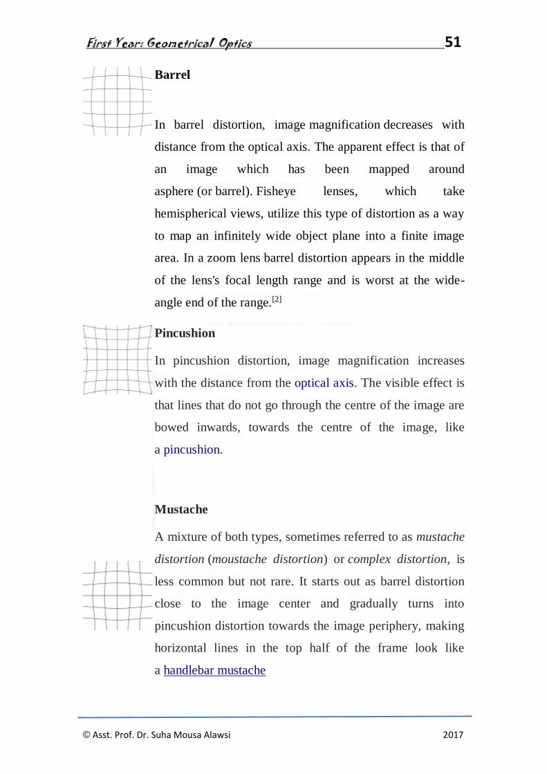
Barrel
In barrel distortion, image magnification decreases with
distance from the optical axis. The apparent effect is that of
an image which has been mapped around
asphere (or barrel). Fisheye lenses, which take
hemispherical views, utilize this type of distortion as a way
to map an infinitely wide object plane into a finite image
area. In a zoom lens barrel distortion appears in the middle
of the lens's focal length range and is worst at the wide-
angle end of the range.[2]
Pincushion
In pincushion distortion, image magnification increases
with the distance from the optical axis. The visible effect is
that lines that do not go through the centre of the image are
bowed inwards, towards the centre of the image, like
a pincushion.
Mustache
A mixture of both types, sometimes referred to as mustache
distortion (moustache distortion) or complex distortion, is
less common but not rare. It starts out as barrel distortion
close to the image center and gradually turns into
pincushion distortion towards the image periphery, making
horizontal lines in the top half of the frame look like
a handlebar mustache
First Year: Geometrical Optics 52
© Asst. Prof. Dr. Suha Mousa Alawsi 2017
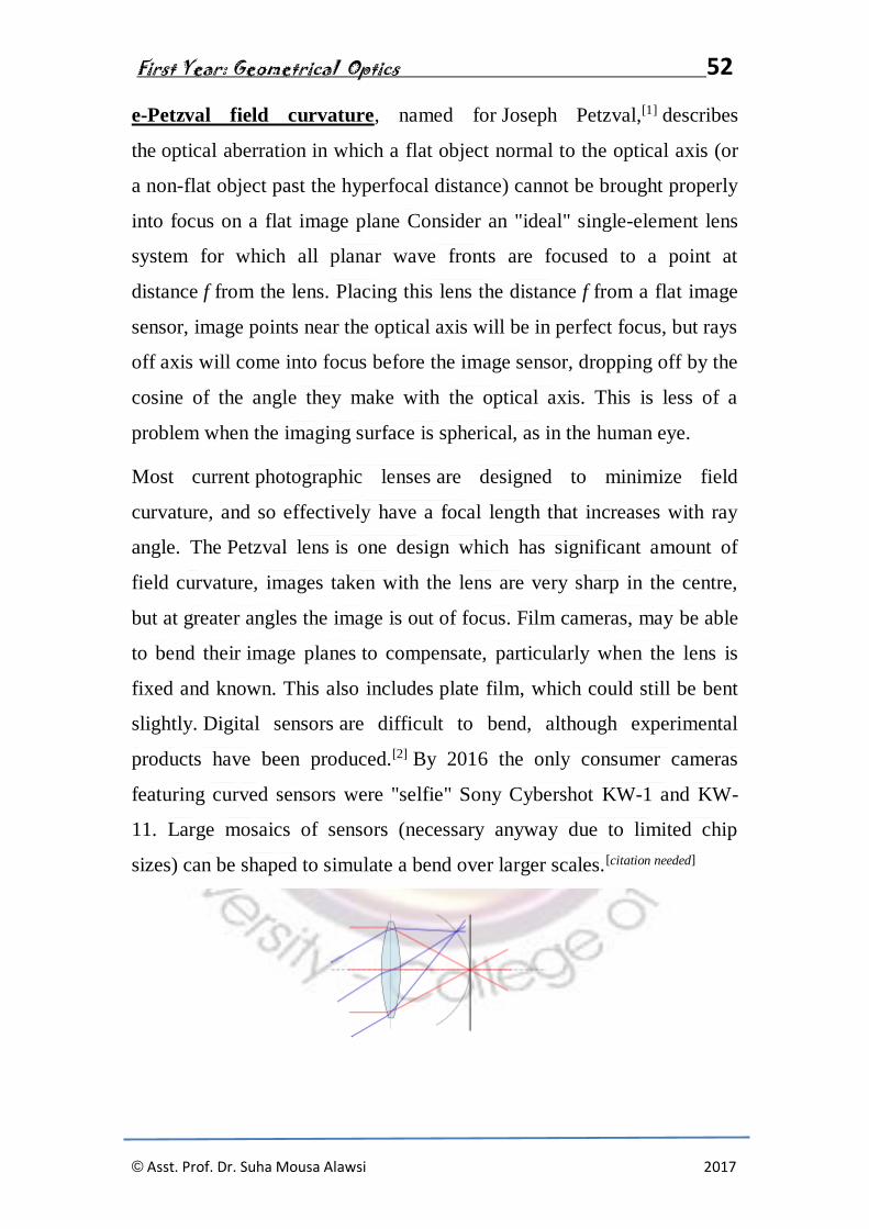
e-Petzval field curvature, named for Joseph Petzval,[1] describes
the optical aberration in which a flat object normal to the optical axis (or
a non-flat object past the hyperfocal distance) cannot be brought properly
into focus on a flat image plane Consider an "ideal" single-element lens
system for which all planar wave fronts are focused to a point at
distance f from the lens. Placing this lens the distance f from a flat image
sensor, image points near the optical axis will be in perfect focus, but rays
off axis will come into focus before the image sensor, dropping off by the
cosine of the angle they make with the optical axis. This is less of a
problem when the imaging surface is spherical, as in the human eye.
Most current photographic lenses are designed to minimize field
curvature, and so effectively have a focal length that increases with ray
angle. The Petzval lens is one design which has significant amount of
field curvature, images taken with the lens are very sharp in the centre,
but at greater angles the image is out of focus. Film cameras, may be able
to bend their image planes to compensate, particularly when the lens is
fixed and known. This also includes plate film, which could still be bent
slightly. Digital sensors are difficult to bend, although experimental
products have been produced.[2] By 2016 the only consumer cameras
featuring curved sensors were "selfie" Sony Cybershot KW-1 and KW-
11. Large mosaics of sensors (necessary anyway due to limited chip
sizes) can be shaped to simulate a bend over larger scales.[citation needed]
First Year: Geometrical Optics 53
© Asst. Prof. Dr. Suha Mousa Alawsi 2017
2- Chromatic Aberration
There are two types of chromatic aberration: axial (longitudinal),
and transverse (lateral). Axial aberration occurs when different
wavelengths of light are focused at different distances from the lens, i.e.,
different points on the optical axis (focus shift). Transverse aberration
occurs when different wavelengths are focused at different positions in
the focal plane (because the magnification and/ordistortion of the lens
also varies with wavelength; indicated in graphs as (change in)
focus length). The acronym LCA is used, but ambiguous, and may refer
to either longitudinal or lateral CA; for clarity, this article uses "axial"
(shift in the direction of the optical axis) and "transverse" (shift
perpendicular to the optical axis, in the plane of the sensor or film).[2]
These two types have different characteristics, and may occur together.
Axial CA occurs throughout the image and is specified by optical
engineers, optometrists, and vision scientists in the unit of focus known
widely as diopters,[4] and is reduced by stopping down. (This
increases depth of field, so though the different wavelengths focus at
different distances, they are still in acceptable focus.) Transverse CA does
not occur in the center, and increases towards the edge, but is not affected
by stopping down.
In digital sensors, axial CA results in the red and blue planes being
defocused (assuming that the green plane is in focus), which is relatively
difficult to remedy in post-processing, while transverse CA results in the
red, green, and blue planes being at different magnifications
(magnification changing along radii, as in geometric distortion), and can
be corrected by radially scaling the planes appropriately so they line up.

First Year: Geometrical Optics 54
© Asst. Prof. Dr. Suha Mousa Alawsi 2017
Chromatic correction of visible and near infrared wavelengths. Horizontal
axis shows degree of aberration, 0 is no aberration. Lenses: 1: simple, 2:
achromatic doublet, 3: apochromatic and 4: superachromat.
In the earliest uses of lenses, chromatic aberration was reduced by
increasing the focal length of the lens where possible. For example, this
could result in extremely long telescopes such as the very long aerial
telescopes of the 17th century. Isaac Newton's theories about white
light being composed of a spectrum of colors led him to the conclusion
that uneven refraction of light caused chromatic aberration (leading him
to build the first reflecting telescope, his Newtonian telescope, in 1668[5]).
There exists a point called the circle of least confusion, where chromatic
aberration can be minimized.[6] It can be further minimized by using
an achromatic lens or achromat, in which materials with differing
dispersion are assembled together to form a compound lens. The most
common type is an achromatic doublet, with elements made
of crown and flint glass. This reduces the amount of chromatic aberration
over a certain range of wavelengths, though it does not produce perfect
correction. By combining more than two lenses of different composition,
the degree of correction can be further increased, as seen in
First Year: Geometrical Optics 55
© Asst. Prof. Dr. Suha Mousa Alawsi 2017
an apochromatic lens orapochromat. Note that "achromat" and
"apochromat" refer to the type of correction (2 or 3 wavelengths correctly
focused), not thedegree (how defocused the other wavelengths are), and
an achromat made with sufficiently low dispersion glass can yield
significantly better correction than an achromat made with more
conventional glass. Similarly, the benefit of apochromats is not simply
that they focus 3 wavelengths sharply, but that their error on other
wavelength is also quite small.[7]
Many types of glass have been developed to reduce chromatic aberration.
These are low dispersion glass, most notably, glasses containing fluorite.
These hybridized glasses have a very low level of optical dispersion; only
two compiled lenses made of these substances can yield a high level of
correction.[8]
The use of achromats was an important step in the development of
the optical microscope and in telescopes.
An alternative to achromatic doublets is the use of diffractive optical
elements. Diffractive optical elements are able to generate arbitrary
complex wave fronts from a sample of optical material which is
essentially flat.[9] Diffractive optical elements have negative dispersion
characteristics, complementary to the positive Abbe numbers of optical
glasses and plastics. Specifically, in the visible part of the spectrum
diffractives have a negative Abbe number of −3.5. Diffractive optical
elements can be fabricated using diamond turningtechniques.[10]

First Year: Geometrical Optics 56
© Asst. Prof. Dr. Suha Mousa Alawsi 2017
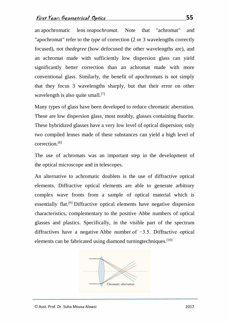
Chromatic aberration of a single lens causes different wavelengths of
light to have differing focal lengths
Diffractive optical element with complementary dispersion properties to
that of glass can be used to correct for color aberration
For an achromatic doublet, visible wavelengths have approximately the
same focal length