Embed Size (px)
Citation preview
Geometry Engine Optimization: Cache Friendly Compressed Representation ofGeometry
Jatin ChhuganiIntel Corporation,Santa Clara, CA
Subodh Kumar∗Indian Institute of Technology,
New Delhi, India
Abstract
Recent advances in graphics architecture focus on improving tex-ture performance and pixel processing. These have paralleled ad-vances in rich pixel shading algorithms for realistic images. How-ever, applications that require significantly more geometry process-ing than pixel processing suffer due to limited resource being de-voted to the geometry processing part of the graphics pipeline. Wepresent an algorithm to improve the effective geometry processingperformance without adding significant hardware. This algorithmcomputes a representation for geometry that reduces the bandwidthrequired to transmit it to the graphics subsystem. It also reducesthe total geometry processing requirement by increasing the effec-tiveness of the vertex cache. A goal of this algorithm is to keep theprimitive assembly simple for easy hardware implementation.
CR Categories: I.3.1 [Computer Graphics]: HardwareArchitecture—Graphics Processors; E.4.0 [Data]: Coding and In-formation Theory—Data Compaction and Compression.
Keywords: Graphics hardware cache, data compression, interac-tive navigation.
1 IntroductionIn recent years, graphics hardware design has made spectacular ad-vances in efficiency as well as in generality and programmability.These improvements have come in the form of faster processors,more memory and caches, and faster buses. On the other hand,models used in applications have also grown larger and shadingmore complex. They have more triangles and vertices, more at-tributes per vertex and longer shaders. Detailed models of airplanes,high resolution medical data, and even 3D game environments [Id-Software 2005] consist of several million polygons and more. In-deed, we expect the size and complexity of models used in thetoughest applications to remain a step ahead of the hardware. Theseapplications will increasingly demand more computation, memory,and bandwidth.
Graphics hardware is designed for efficient rendering of triangles.The rendering pipeline starts when a user specifies the geometryand continues until pixel data is written into the frame buffer. Webroadly partition rendering into three stages: data gathering, geom-etry operations, and pixel operations, each of which must remainseparately efficient. This implies that in addition to fast vertex andfragment processing, effective interfaces to specify geometry must
∗most of the work was done while the author was at the Johns HopkinsUniversity, Baltimore, MD.
exist so that data gathering, which includes transmission from theapplication to the geometry engine, may be fast.
Data gathering and geometry processing are the subject of this pa-per. These may be further subdivided into per-vertex operations andper primitive operations. We focus our attention on the primitiveaspects: in particular, on reducing the size of primitive representa-tion and on reducing the computation required for each primitive.Vertex attribute compression and per vertex computation, which aresurely at least as important, are complimentary to this effort and outof the scope of this paper.
Our input domain is a triangular mesh: a sequence of triangles thatshare vertices. Typically there are only about half as many uniquevertices in a mesh as there are triangles but there are thrice as manyreferences. A naive geometry engine would process each vertex sixtimes, repeatedly fetching and shading it. A more efficient strip-like representation still results in each vertex being processed atleast twice. For vertex shader limited applications this could halveoverall performance. That is why popular graphics architecturesbuild in a post-shader vertex cache. If this cache were large enoughto fit all attributes of every vertex in the model, one would neverhave to repeat the processing of any vertex. However, a fast cachethat large is simply not practical. That is why eight or sixteen en-try caches are commonly used. If vertex-references in a list of tri-angles are near each other, the cache is well utilized. We devisea compressed primitive-topology representation that ensures highvertex coherence. Furthermore, in addition to a high compressionratio, we ensure the simplicity of the decompression algorithm, soits overhead is negligible.
We have taken the minimalist approach of primarily staying withinthe constraints of the currently popular architecture. We do requirethat the triangles be specified in an order suitable for efficient pro-cessing. Sometimes applications need to maintain total control overit. However, most applications do not care about the specific orderof primitives that share a common state, especially if the order isrepeatable for a static model.
For a model with n unique vertices, each of which must be pro-cessed at least once, a minimum of n cache misses are necessary.We define the cache miss ratio as the number of vertices per trian-gle that must be shaded because they are not already in cache. Thusfor a model with m triangles and n vertices, the minimum ratio isM = n
m . In practice, m ∼ 2n, and hence M is at least 0.5. In orderto guarantee a cache miss ratio of 0.5, it is necessary to use a cacheof size O(
√n) in general [Bogomjakov and Gotsman 2001]. In re-
ality, an unlimited cache is not practical. Although other variantsare possible, for simplicity we assume a small post vertex-shadingsingle-level FIFO cache [Nvidia 2001].
Significant vertex attribute compression is indeed possible[Purnomo et al. 2005]. However, vertex compression alone cannotalways relieve the bandwidth bottleneck and mesh topology mustbe compressed as well. Hence it is imperative to not only makethe topological information cache friendly, but to also compressit. Most research into topology compression does not focus onefficient hardware decompression and cache coherence, and vice-versa. That is the contribution of this paper: it compresses well,
decompresses efficiently and maintains cache coherence, all at thesame time. Although, we do not discuss the problem of vertex com-pression here, we note that our algorithm clusters nearby verticestogether, thereby lending itself naturally to quantization based ver-tex attribute compression schemes like [Purnomo et al. 2005].
1.1 Previous WorkGeometry compression includes compressing vertex attributes (likeposition, normals, texture coordinates, etc.) along with the topologyinformation. Vertex attribute compression algorithms [Chow 1997;Purnomo et al. 2005] are typically lossy in nature and quantizethe data by exploiting the coherence between neighboring vertices.Topology (or connectivity) compression is generally lossless andhas been an active area of research [Taubin and Rossignac 1998;Gumhold and Strasser 1998; Szymczak et al. 2001; Isenburg 2001;Alliez and Desbrun 2001; Kronrod and Gotsman 2002]. However,these algorithms [Szymczak et al. 2001] do not produce a cachecoherent representation and typically encounter one cache miss pertriangle for typical hardware cache sizes (8-64). Moreover, only afew algorithms are intended [Deering 1995; Chow 1997] for hard-ware decompression. Reducing the cache misses is of critical im-portance since it reduces both the time and hardware resources tofetch the pre-transformed vertex attributes when they are requiredduring rasterization. The problem of reducing the cache misses hasalso been investigated separately [Bar-Yehuda and Gotsman 1996;Bogomjakov and Gotsman 2001; Hoppe 1999; Yoon et al. 2005].
Although compression algorithms suited for “polygon soups” ex-ist [Gueziec et al. 1999; Gandoin and Devillers 2002], the mostcompression is achieved when models are (orientable) manifolds,or may be decomposed into manifolds [Touma and Gotsman 1998;Szymczak et al. 2001; Gumhold and Strasser 1998]. Most recentgeometry compression algorithms are based on a spanning tree ofthe adjacency graph [Rossignac 1999] or on a separation of thevertices [Touma and Gotsman 1998]. Both classes of methodsseem unsuitable for hardware decompression. Not only are thesteps somewhat complex, the temporary memory required can belarge. The method proposed earlier by [Deering 1995] is de-signed for hardware. They present a “generalized mesh” repre-sentation, which can be efficiently compressed and decompressedusing a fixed memory size. This technique still requires variablelength components and has not been adopted in popular architec-tures. Our method is inspired by this technique. We first extend itto improve its performance, and then show how the extensions canbe implemented in simpler operations, which require simpler hard-ware. [Chow 1997] shows how to compute the generalized meshrepresentation from a vertex array. Triangle strips are also poten-tially well suited for compression [Isenburg 2001]. Generation oflong triangle strips from a given vertex array has been active areaof research [Estkowski et al. 2002; Xiang et al. 1999; Evans et al.1996; Diaz-Gutierrez et al. 2006].
[Hoppe 1999] solve the problem of effective utilization of a fixedsize vertex cache. The algorithm computes an order for issuing ver-tices by greedily growing strips of lengths appropriate for a givencache size. It further improves the strips with a local optimiza-tion technique that perturbs the triangle order to improve cache ef-fectiveness. It also discusses size trade offs between using stripsand vertex arrays. Later [Bogomjakov and Gotsman 2001] consid-ers the theoretical problem of determining the minimal cache sizethat guarantees only n cache misses for a manifold with n vertices.[Yoon et al. 2005] present an out-of-core algorithm for cache obliv-ious layouts of meshes. It transforms the given mesh into a graphand gives an approximate solution for the permutation of the nodeswhich reduces the length of their edge dependency. This leads toa reduction in number of cache misses, which improves with theincrease in the size of the cache. [Yoon and Lindstorm 2006] pro-
vides metrics to access the quality of meshes for block-based cachesand can be used to improve the layouts for meshes. [Lin and Yu2006] also proposes a vertex caching scheme where it formulatesthe problem as a linear optimization function of the mesh topologyand the vertex state in a simulated cache buffer. The algorithm alsohandles progressive meshes by adaptively updating the reorderedsequence at full detail.
1.2 OverviewWe have chosen to further develop the compression technique of[Deering 1995] and [Chow 1997] to
1. incorporate cache coherence.
2. improve the compression of the geometry stream.
3. make it more suitable for current hardware.
[Deering 1995] describes a generalized triangle mesh representa-tion, which specifies one vertex per most triangle in addition tocodes for labels Restart, Replace-Oldest, Replace-Middle and Push,which specify how to connect that vertex to the latest triangle. Thisis a generalization of triangle strips, in which the connection of thenew vertex to the latest triangle is predetermined. It also has thefacility to directly refer to a “mesh buffer” address, which is akin toa vertex cache. [Chow 1997] provides an algorithm to compute ageneralized mesh from a vertex array, but it is designed to maximizethe reuse of cache addresses. We improve that algorithm to increasethe reuse of cache entries (and thus improve coherence as well ascompression). We are motivated in this algorithm by the “cachesimulation” idea of [Hoppe 1999], but lower the cache miss ratiofurther. In addition, we encode even the cache-misses efficiently.Finally, in order to make the algorithm better fit the current graph-ics architecture, we propose conversion of the resulting generalizedtriangle mesh into a compact, per triangle representation.
Our experiments as well as those by others [Hoppe 1999] showthat cache coherence does not significantly improve with cache re-placement policies more sophisticated than FIFO. Even if we allowa geometry stream to fully control the entries that may be replacedin cache, the miss ratio M does not improve significantly. Given thesimplicity of the FIFO policy, we base the rest of our design on aFIFO cache.
The main steps of our algorithm are as follows:
1. Decompose the mesh into parallel chains of vertices.
2. Induce cuts along each chain to derive the vertex issue orderfor the cache.
3. Generate a mesh representation that issues the vertices in thedesired order.
4. Order vertices in the vertex array in the order of their firstissue.
5. Entropy-encode the resulting mesh.
2 Cache PerformanceIn order to improve the vertex cache performance, we need to min-imize the number of times a vertex is loaded into the cache. Sinceevery vertex is loaded at least the first time it is accessed, we wouldideally like to render all its incident triangles before it is flushed out.For a constant size (say, k) cache, we cannot satisfy this for all thevertices simultaneously [Bogomjakov and Gotsman 2001]. Thisgives rise to the Face Reordering Problem [Hoppe 1999]: GivenT , the set of triangles in the input mesh, find a permutation of thetriangles π0(T ), such that C(π0(T )) ≤C(π(T )), where C(T ) is the
number of cache misses for T , and π(T ) is any of the m! valid per-mutation of the m triangles in T . Bar-Yehuda et al. [Bar-Yehudaand Gotsman 1996] present an algorithm that generates n(1 + c
k )cache misses, (for a constant c), and runs in O( n2
k2 ) time. The com-plexity categorization of the Face Reordering Problem is an openquestion.
Recall that we aim to find a representation that not only reduces thenumber of cache misses, but also reduces the size of data sent tothe graphics card. It turns out that by solving the former, we get arepresentation that gives a simple scheme to compress the indices.These indices can be decompressed in the hardware. To enablethis, we replace T by T ′, where T ′ = T
⋃
X , where X is a set ofdegenerate triangles. A degenerate triangle is formed from two orfewer unique vertices. Further, to avoid any line artifacts, we mayform a degenerate triangle by replicating a vertex thrice.
2.1 Reducing Cache MissesOur algorithm, instead of ordering triangles like many others, di-rectly orders vertices first to optimize cache usage. It then reordersthe triangles so that the resulting traversal introduces the verticesinto the cache in that given order. Our final representation is sim-ilar to generalized triangle strip [Chow 1997]. However, we usethe actual cache size, k, to locally optimize the length of the stripsto try to retain a vertex in cache until all its incident triangles havebeen rendered. We will argue later that the knowledge of the ac-tual cache size is not crucial for our approach to work well. Thereaccess independent 1 nature of FIFO aids in finding such an or-der. This solution is only locally optimal, but in practice it doesapproach the n(1 + 1
k ) bound [Bar-Yehuda and Gotsman 1996] forthe cache misses.
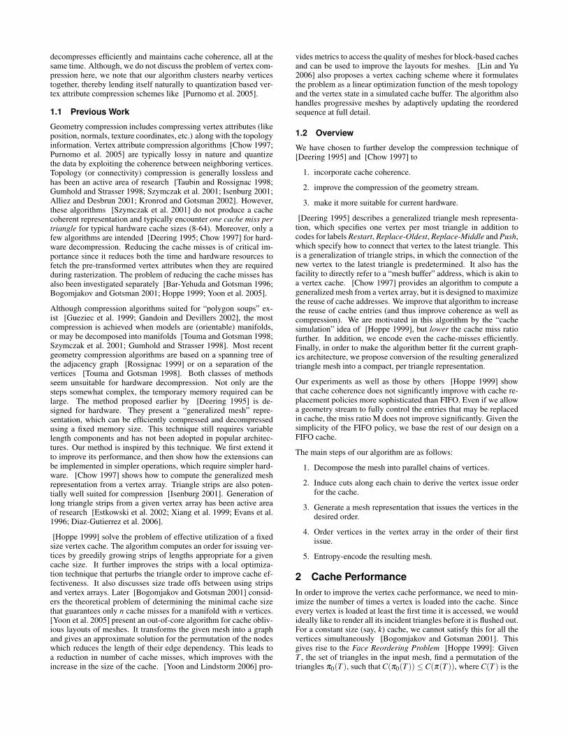
The following example demonstrates our underlying approach.Consider the regular mesh shown in Figure 1, which is replicatedfrom [Hoppe 1999]. Let us divide it into rows of vertices (num-bered V1..Vr) (Figure 2). The triangles are also numbered in a rowmajor fashion, with triangles between rows i and i+1 forming rowTi of triangles. A total of r−1 rows of triangles are formed.
Figure 1: Grid20: a mesh with 391 vertices and 704 triangles.
First, assume the cache is larger than the number of vertices in anytwo consecutive rows. Now, say, we render the rows of trianglesin increasing order. The triangles in a row are issued so that theorder in which the vertices enter the cache is similar to the order
1In FIFO, the priority of a vertex is determined by the time of its intro-duction into the cache. Thus, even if a vertex is accessed repeatedly from acache, its priority does not change. Hence a vertex remains in the cache fora fixed number of cache miss events. This fact is exploited by our algorithmas we try to load all neighboring vertices of a particular vertex before thesubsequent (fixed number of) cache misses occur.
in which they appear in that row. For example, in row V1: V1,5 isissued before V1,6. Note, though, that T1 uses vertices from bothV1 and V2, and hence as a boundary condition, we must ‘warm-up’the cache with the vertices in row V1 issued as degenerate triangles.Now when triangles in row T1 are issued from left to right, verticesin row V2 will be issued from left to right too. Note that we have notreloaded any vertex so far, and none of the vertices of the first roware flushed out. After the row T1, the triangles in row T2 are issued.This brings into the cache, the vertices in V3 in a similar fashion,while potentially flushing out the vertices of V1. Hence, we are ableto render the whole mesh without reloading any vertex. Of course,we allowed a potentially large cache size. For a fixed cache size k,we adapt our solution as follows. We cut the mesh into several sub-meshes by subdividing along the width, and perform one pass of thealgorithm described above for each cut. If the row-width of each cutis smaller than k -1, we do not reload any vertex for the first pass.On the other hand, the last vertex of each row will be required againfor the second cut, and hence potentially result in cache misses.Figure 6 shows these cuts. For this example, we subdivide the meshinto two cuts with eighteen vertices being reloaded.
Finally, let us generalize to non-regular meshes. For any generalmesh, the degree of the vertices may vary substantially. This dic-tates the way we choose our cuts: we want to minimize the numberof edges having endpoints in different cuts, as well as the numberof cuts. This general algorithm is phrased in terms of the discussionabove:
• Form rows of vertices (chains) for the mesh.
• Order the vertices within each chain.
• Form cuts of vertices for each row in accordance with the con-nectivity information and the cache size k.
• Form a list of triangles (including degenerate triangles) thatpreserves the vertex order while they are loaded into thecache.
Each step is explained in detail next.
2.1.1 Forming Chains (Rows of Vertices)
We expect the input mesh to be a 2-manifold (with/without bound-ary). A non-manifold mesh can be broken down into manifolds[Szymczak et al. 2001; Touma and Gotsman 1998].
Figure 2: Ordering of the vertices for Grid20. The index of someof the vertices is shown. Vertices with the same color belong to thesame chain.
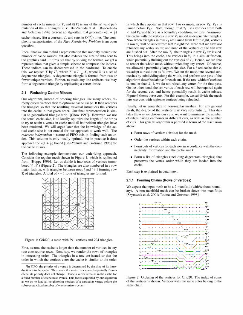
Given the set of all vertices, V , consider a subset V1, such that ver-tices in V1 form a connected path. As an example, say we choosethe vertices V1,1..V1,20 in Figure 2. Now perform a Breadth FirstSearch (BFS) of the input mesh and find all the vertices in V thatare connected to at least one vertex in V1. Each level of the BFSsearch would form a chain. Some of these chains may not form aconnected path. In this example, we find all the vertices in V thatare connected to at least one vertex in V1. Denote this set as V2.Continue forming such sets so that each vertex in Vi is connectedto at least one vertex in Vi−1. Say we form l such sets of vertices,V1..Vl , which represent the l chains in the model. The total run-ning time of this step is O(m + n). The choice of the starting pathis arbitrary. For example, V1 could be assigned the vertex with theminimum or maximum degree. Figure 3 shows the different chainsfor different starting heuristics. The figure on the top left corner hasthe top row of vertices as the first chain, while the top right cornerhas the starting chain as the vertex with the minimum degree. Boththese figures depict the Grid20 model. The figures on the bottomof Figure 3 use the vertex with the maximum degree as the initialchain. Note that near the boundaries of meshes, these chains maynot form a connected path (V20 of Figure 2). Let si = |Vi| and smax= max j(s j).
2.1.2 Vertex Ordering within each chain
Having obtained the chains of vertices, we now impose an orderingwithin each chain. Start with V1. Since it forms a path, an orderingis already implicit. For each vertex v in V2, store Pv, the orderedlist of IDs of vertices in V1 that have an edge with v. Now sort (inincreasing order) the vertices in V2, with Pv as the key. In case ofties (i.e. two or more vertices in V2 having the same set of edgeneighbors in V1), we maintain the order imposed by the edges in-terconnecting such vertices. This defines the local order of suchvertices. We further look at the previous and next set of neighbor-ing vertices (if available) to choose the first (or respectively last)vertex amongst such sets. The rest of the vertices follow the localorder just defined. We continue iterating over all rows. Thus, thevertex order in Vi determines the ordering of Vi+1. Figure 2 showsthe ordering of vertices for our example. The running time for thisstep is O(lsmax log(smax)), which for certain extreme meshes couldbe O(n log(n)).
Figure 3: Vertices with the same color belong to one chain. Top:Different rows of vertices using different starting heuristics forGrid20. Bottom Left: Rows of vertices (chains) generated for theBunny model. Bottom Right: Chains generated for the teeth model.
2.1.3 Forming Cuts in each chainA cut is defined as a subset of vertices within each chain. Recallthat each vertex of the mesh can be indexed using a pair of indices(i, j), where i refers to the chain number and j is the index within thechain. For a vertex v , we refer its vertex neighbors (within the cut)belonging to the same chain but having an index less than it as itas its left neighbors. The right neighbors are similarly defined. Thetop neighbors refer to its vertex neighbors belonging to the previous((i−1)th)chain. The bottom neighbors belong to the next ((i+1)th)chain. We use the term row and chain interchangeably.
The subset of triangles having all their end points within these sub-chains would be reordered in such a way that the subset of vertices(i.e., those included in the cut) in the ith chain are introduced intothe cache before the corresponding subset of vertices in the (i+1)th
chain. Moreover we need to ensure that none of these vertices arereloaded (while rendering the cut). Hence the following propertiesneed to be satisfied:
1. A vertex v stays in the cache until all its right and bottomneighbors have been loaded in the cache. Hence all its adja-cent triangles would be rendered before it is discarded.
2. A vertex v is included in the current cut if all its left neighbors(if it has any) satisfy Property 1.
3. However, for a cache size k, a vertex v is included only if:
(a) Not more than k vertices are chosen for any chain.
(b) The number of unique bottom neighbors of vertices be-fore it in the chain is less than k.
4. The sum of the number of unique bottom neighbors of verticesbefore and including v and the number of right neighbors of vshould be the largest possible value less than k.
Property 1 ensures that all incident triangles to a vertex are renderedbefore it is flushed out. Property 2 aims to include more vertices inthe cache provided Property 3 is satisfied. Property 3(a) respectsthe cache size limitations while Properties 3(b) and 4 aim towardsremoving a vertex as soon as all its adjacent vertices have beenloaded.
We have devised the following 2-pass linear-time algorithm thataccomplishes the above by simulating the cache.
1. We process vertices in their assigned order. Say the currentvertex is v. We consider all neighbors w1, ..,wdv of v. wi needsto be fetched into cache if any of the two neighboring trianglesto the edge ¯vwi have not been rendered so far. Otherwise vdoes not require wi to be loaded.
2. After simulating Step 1 for k vertices for a row, we need tofind the actual cut for that row. We keep a counter of thenumber of vertices that can be loaded for a particular row,initialized to (k-1). When we select the first available vertex,we decrement the counter by the number of unique bottomneighbors that this vertex would introduce to the cache. Wekeep adding vertices to the current cut while the counter is ≥0. We then advance to the next row.
Figure 4 shows a step-by-step movement of adding vertices for aparticular row to a cut. Say we have a cache of size 8. When weselect the first vertex of row i (Fig. 4(a)), the counter value reducesto 3 (since we need to accommodate this vertex and its 4 bottomneighbors). Now consider the second vertex in row i (Fig. 4(b)).Including this vertex into the cut would introduce just one new bot-tom neighbor, and the counter value would become two. Hence weinclude this vertex in the current cut, and further advance our cut.All the vertices included in the cut are colored red. The third vertex
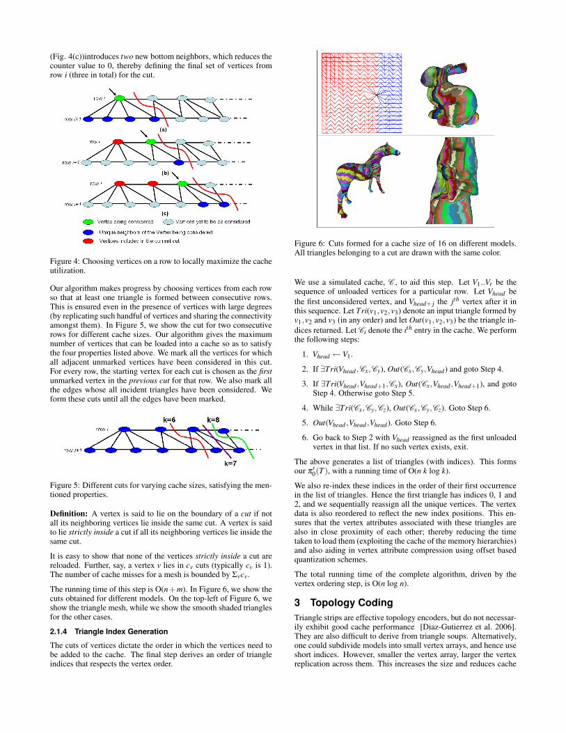
(Fig. 4(c))introduces two new bottom neighbors, which reduces thecounter value to 0, thereby defining the final set of vertices fromrow i (three in total) for the cut.
Figure 4: Choosing vertices on a row to locally maximize the cacheutilization.
Our algorithm makes progress by choosing vertices from each rowso that at least one triangle is formed between consecutive rows.This is ensured even in the presence of vertices with large degrees(by replicating such handful of vertices and sharing the connectivityamongst them). In Figure 5, we show the cut for two consecutiverows for different cache sizes. Our algorithm gives the maximumnumber of vertices that can be loaded into a cache so as to satisfythe four properties listed above. We mark all the vertices for whichall adjacent unmarked vertices have been considered in this cut.For every row, the starting vertex for each cut is chosen as the firstunmarked vertex in the previous cut for that row. We also mark allthe edges whose all incident triangles have been considered. Weform these cuts until all the edges have been marked.
Figure 5: Different cuts for varying cache sizes, satisfying the men-tioned properties.
Definition: A vertex is said to lie on the boundary of a cut if notall its neighboring vertices lie inside the same cut. A vertex is saidto lie strictly inside a cut if all its neighboring vertices lie inside thesame cut.
It is easy to show that none of the vertices strictly inside a cut arereloaded. Further, say, a vertex v lies in cv cuts (typically cv is 1).The number of cache misses for a mesh is bounded by Σvcv.
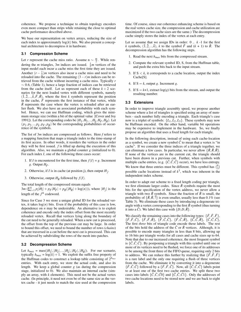
The running time of this step is O(n+m). In Figure 6, we show thecuts obtained for different models. On the top-left of Figure 6, weshow the triangle mesh, while we show the smooth shaded trianglesfor the other cases.
2.1.4 Triangle Index GenerationThe cuts of vertices dictate the order in which the vertices need tobe added to the cache. The final step derives an order of triangleindices that respects the vertex order.
Figure 6: Cuts formed for a cache size of 16 on different models.All triangles belonging to a cut are drawn with the same color.
We use a simulated cache, C , to aid this step. Let V1..Vr be thesequence of unloaded vertices for a particular row. Let Vhead bethe first unconsidered vertex, and Vhead+ j the jth vertex after it inthis sequence. Let Tri(v1,v2,v3) denote an input triangle formed byv1,v2 and v3 (in any order) and let Out(v1,v2,v3) be the triangle in-dices returned. Let Ci denote the ith entry in the cache. We performthe following steps:
1. Vhead ← V1.
2. If ∃Tri(Vhead ,Cx,Cy), Out(Cx,Cy,Vhead) and goto Step 4.
3. If ∃Tri(Vhead ,Vhead+1,Cx), Out(Cx,Vhead ,Vhead+1), and gotoStep 4. Otherwise goto Step 5.
4. While ∃Tri(Cx,Cy,Cz), Out(Cx,Cy,Cz). Goto Step 6.
5. Out(Vhead ,Vhead ,Vhead). Goto Step 6.
6. Go back to Step 2 with Vhead reassigned as the first unloadedvertex in that list. If no such vertex exists, exit.
The above generates a list of triangles (with indices). This formsour π ′0(T ), with a running time of O(n k log k).
We also re-index these indices in the order of their first occurrencein the list of triangles. Hence the first triangle has indices 0, 1 and2, and we sequentially reassign all the unique vertices. The vertexdata is also reordered to reflect the new index positions. This en-sures that the vertex attributes associated with these triangles arealso in close proximity of each other; thereby reducing the timetaken to load them (exploiting the cache of the memory hierarchies)and also aiding in vertex attribute compression using offset basedquantization schemes.
The total running time of the complete algorithm, driven by thevertex ordering step, is O(n log n).
3 Topology CodingTriangle strips are effective topology encoders, but do not necessar-ily exhibit good cache performance [Diaz-Gutierrez et al. 2006].They are also difficult to derive from triangle soups. Alternatively,one could subdivide models into small vertex arrays, and hence useshort indices. However, smaller the vertex array, larger the vertexreplication across them. This increases the size and reduces cache
coherence. We propose a technique to obtain topology encoderseven more compact than strips while retaining the close to optimalcache performance described above.
We base our representation on vertex arrays, reducing the size ofeach index to approximately log(k) bits. We also present a concep-tual architecture to decompress it in hardware.
3.1 Compression SchemeLet r represent the cache miss ratio. Assume n ∼ m
2 . While ren-dering the m triangles, 3m indices are issued. 1
2 m vertices of theinput model each incur a cache miss the first time they are issued.Another (r− 1
2 )m vertices also incur a cache miss and need to bereloaded into the cache. The remaining (3− r)m indices can be re-trieved from the cache without incurring a cache miss. Typically r∼ 0.6, (Table 1), hence a large fraction of indices can be retrievedfrom the cache itself. Let us represent each of these k + 2 sce-narios for the next loaded vertex with different symbols, namely(1, 2, .., k, F, R), where the first k symbols represent the positionin the cache, F represents the first instance of that vertex, whileR represents the case where the vertex is reloaded after an ear-lier flush. We also have an associated probability with each sym-bol. Hence, we can use Huffman coding, which gives the mini-mum storage size (within a bit of the optimal value [Cover and Joy1991]). Let the corresponding codes be (H1,H2, ..,Hk,HF ,HR). Let(p1, p2, .., pk, pF , pR) be the corresponding probabilities of occur-rence of the symbols.
The list of 3m indices are compressed as follows. Here f refers toa mapping function that maps a triangle index to the time-stamp ofits first access. In other words, it reorders the vertices in the orderthey will be first issued. f is filled up during the execution of thisalgorithm. Also, we maintain a global counter g (initialized to 0).For each index I, one of the following three cases occur:
1. If I is encountered for the first time, then f (I) = g. Incrementg. Output HF .
2. Otherwise, if I is in cache (at position j), then output H j .
3. Otherwise, output HR followed by f (I).
The total length of the compressed stream equals3m (∑k
i=1 pi|Hi|+ pF |HF |+ pR(|HR|+ log(n))), where |H j| is thelength of the jth codeword.
Since for Case 3 we store a unique global ID for the reloaded ver-tex, it takes log(n) bits. Even if the probability of this case is low,dependence on n may be undesirable. An alternative is to exploitcoherence and encode only the index offset from the most recentlyreloaded vertex. Recall that vertices lying along the boundary ofthe cut need to be generally reloaded. When a new cut is processed,the offset from the top of the previous cut may be large. In orderto bound this offset, we need to bound the number of rows (chains)that are traversed in a cut before the next cut is processed. This canbe achieved by subdividing the rows of the mesh into patches.
3.2 Decompression SchemeLet hmax = max(|H1|, |H2|, .., |Hk|, |HF |, |HR|). For our scenario,typically hmax = log(k)+ 1. We exploit the suffix free property ofthe Huffman codes to construct a lookup table consisting of 2hmax
entries. With each entry, we store the actual code, and also itslength. We keep a global counter g (as during the compressionstage, initialized to 0). We also maintain an internal cache (sim-ply an array, with k elements). This need not be the actual vertexcache. (In principle, it need not even be of the same size as the ver-tex cache - it just needs to match the size used at the compression
time. Of course, since our coherence enhancing scheme is based onthe real vertex cache size, the compression and cache utilization aremaximized if the two cache sizes are the same.) The decompressioncache simply stores the index of the vertex at each entry.
Let us assume that we assign IDs in order: 0 .. k -1 for the firstk symbols, (1, 2, .., k), k to the symbol F and (k + 1) to R. Thedecompression algorithm has the following steps.
1. Read the next hmax bits from the compressed stream.
2. Compute the relevant symbol ID, S, from the Huffman table,and push the extra bits back to the input stream.
3. If S < k, it corresponds to a cache location, output the indexCache[S].
4. If S = k, output g. Increment g.
5. If S = k+1, extract log(g) bits from the stream, and output theresulting number.
3.3 ExtensionsIn order to improve triangle assembly speed, we propose anotherscheme where a list of triangles is specified using an array of num-bers - each number fully encoding a triangle. Each triangle’s casenow is a triplet of symbols: {L1,L2,L3}. These symbols may nowbe Huffman encoded. On the other hand, variable bit operationsmay be expensive to implement in the hardware. So, we finallypropose an algorithm that uses a fixed length for each triangle.
In the following description, instead of using each cache-locationas a symbol, we create a new symbol C to mean that a vertex is “incache”. If we consider the three indices of a triangle together, wecan eliminate a few cases. In particular, we never allow {R, R, R}.If none of the vertices are in the current cut, the triangle shouldhave been drawn in a previous cut. Further, when symbols withmultiple cache entries, (e.g. {C,C,C} occur), we have less entropy.We know that three entries must be different. This symbol has
(k3)
possible cache locations instead of k3, which was inherent in theindependent index scheme.
In order to adapt our scheme to a fixed length coding per triangle,we first eliminate larger codes. Since R symbols require the mostbits for the specification of the vertex address, we never allow atriangle with two R symbols. Since the fraction of R is small, theprobability of {R, R, ?} is even smaller, usually less than 0.1% (seeTable 3). We eliminate these cases by introducing a degenerate tri-angle with a vertex corresponding to the first R symbol (thus turningit into a C). We label this case with {D,D, R}.
We classify the remaining cases into the following types: {F, F, F},{F , F,C}, {F, F, R}, {F ,C,C}, {F,C, R}, {C,C, R}, {C,C,C},The first three bits of triangle code encode these labels. The restof the bits hold the address of the C or R vertices. Although, it ispossible to encode many triangles in less than 8 bits, allowing upto 16 bits per triangle works for all cases and cache sizes up to 64.Note that due to our increased coherence, the most frequent symbolis {C,C,C}. By postponing a triangle with this symbol until one ormore of its vertices need to be flushed, we force one of its addressesto be among the front three of the FIFO queue, requiring only 2 bitsto address. We can reduce this further by realizing that {F, F, F}is a rare label and the only one requiring a flush of three verticesfrom the cache. We eliminate it by converting it into a degenerate{F ,C,C} followed by a {F , F,C}. Now, all {C,C,C} labels pointto at least one of the first two cache entries. We split these twocases into labels {C,C,C0} and {C,C,C1}. Only the addresses oftwo cache locations need to be stored now and we are back to eightlabels.
By our cluster splitting we ensure that most of our R offsets aresmall. The very few that do not fit in 13 bits, we turn into F cases byreplicating all vertex attributes. This allows us to keep the decom-pression simple. The largest remaining code is {C,C, R}, whichuses 3 bits for the case mask and 2log(k)−1 bits for the two cacheaddresses. For our goal of 16 bits per triangle, this still leaves insuf-ficient space for some R indices (for any reasonable k). When 16bits are inadequate, we introduce a degenerate {D,D, R} triangleas described above. The original {C,C, R} triangle now becomes{C,C,C0} or {C,C,C1}. This scheme ensures that the most signif-icant three bits act as a multiplexer into case decoders. The rest ofthe vertex address computation logic is straightforward as well.
4 Results and AnalysisWe tested our algorithm on a variety of models, ranging from a fewthousand triangles to a million triangles. The details of the modelsare given in Table 1.
Model Vertices Triangles Cache Lin et Degen.(n) (m) Miss (r) al. (r) Tris (d)
Grid20 391 704 0.580 0.605 0.029Fandisk 6,475 12,946 0.588 0.595 0.024Bunny 35,947 71,884 0.608 0.597 0.036Horse 48,485 96,966 0.589 0.599 0.026Teeth 116,604 233,204 0.590 0.604 0.029Igea 134,556 269,108 0.573 0.601 0.023Isis 187,644 375,284 0.580 0.603 0.034
Hand 327,323 654,666 0.612 0.606 0.047Tablet 539,446 1,078,890 0.567 0.580 0.023
Table 1: Details of the models used for experimentation. The valuesof r and d are for a FIFO cache of size 16.
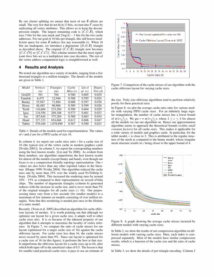
In column 4, we report our cache miss ratio r for a cache size of16 (the typical size of the vertex cache in modern graphics cards[Nvidia 2001]). In column 5, we report the corresponding numbersusing the best known results [Lin and Yu 2006]. As evident fromthese numbers, our algorithm outperforms the best known resultsfor almost all the models (except bunny and hand), even though ourfocus is on a compression friendly topology representation. Our rvalues are also better than any other reported values in the litera-ture [Hoppe 1999; Nvidia 2004]. Our algorithm reduced the cachemiss rate by more than 25% over the widely used NvTriStrip li-brary [Nvidia 2004]. This increased the rendering rates by around10% - 15% as compared to their representation on several nVidiachips. The number of degenerate triangles (column 6) generatedreduces with the increase in cache size, and is never more than 5%of the original triangles for all cache sizes (≥ 16). Our prepro-cessing times vary from a few seconds (for smaller models) to amaximum of few minutes on models consisting of over million tri-angles. Note that this reordering is needed just once in the lifetimeof a static model.Recently [Yoon et al. 2005] described an algorithm for cache obliv-ious layouts of meshes. It is worth pointing out that although weoptimize our layout for a given cache size, it adapts well to othercache sizes also. It is so because of the inherent property of ouralgorithm that it attempts to maximize the locality of vertex refer-ence. In Figure 7, we compare the ratio of cache misses for ourlayout (optimized for a target cache size of 16) against the cacheoblivious layout. For cache sizes less than 16, the cache missesnever exceed by more than 9%. Since our layout is optimized fora cache size of 16 (in this figure), it performs the best at that size.It outperforms the oblivious layout for a cache sizes up to 64, afterwhich both taper off to the amortized value of 0.5. The lesson is thatfor smaller (and practical) cache sizes, it pays to use an estimate of
Figure 7: Comparison of the cache misses of our algorithm with thecache oblivious layout for varying cache sizes.
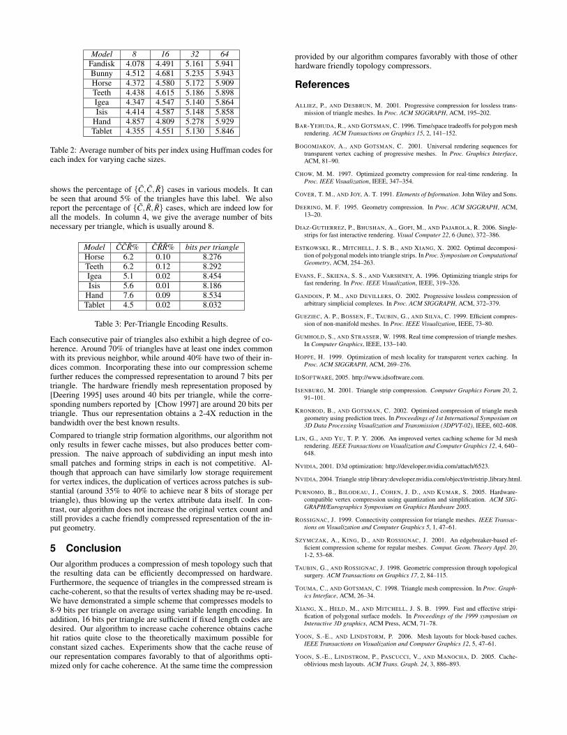
the size. Truly size-oblivious algorithms tend to perform relativelypoorly for these practical sizes.In Figure 8, we plot the average cache miss ratio for various mod-els with varying FIFO cache sizes. For an infinitely large regu-lar triangulation, the number of cache misses has a lower boundof n(1+ 1
k−1 ). We get r = n(1+ ck−1 ), where 2 ≤ c ≤ 4 for almost
all the models we ran our algorithm on. Hence our approximationalgorithm seems to approach the theoretical bounds (within smallconstant factors) for all cache sizes. This makes it applicable fora wide variety of models and graphics cards. In particular, for thetablet model, c is close to 2. This is attributed to the regular struc-ture of the mesh as compared to the bunny model, whose irregularmesh structure results in c being closer to the upper bound of 4.
Figure 8: A graph showing the average cache misses incurred bydifferent models with varying cache sizes.
In Table 2, we show the results of our compression algorithm on dif-ferent models with varying cache sizes. Here, each index is com-pressed separately. Most of the models have similar compressionresults, which is a function of the cache size and the ratio of cachemisses.
In Table 3, we show the details of per-triangle encoding. Column 2
Model 8 16 32 64Fandisk 4.078 4.491 5.161 5.941Bunny 4.512 4.681 5.235 5.943Horse 4.372 4.580 5.172 5.909Teeth 4.438 4.615 5.186 5.898Igea 4.347 4.547 5.140 5.864Isis 4.414 4.587 5.148 5.858
Hand 4.857 4.809 5.278 5.929Tablet 4.355 4.551 5.130 5.846
Table 2: Average number of bits per index using Huffman codes foreach index for varying cache sizes.
shows the percentage of {C,C, R} cases in various models. It canbe seen that around 5% of the triangles have this label. We alsoreport the percentage of {C, R, R} cases, which are indeed low forall the models. In column 4, we give the average number of bitsnecessary per triangle, which is usually around 8.
Model CCR% CRR% bits per triangleHorse 6.2 0.10 8.276Teeth 6.2 0.12 8.292Igea 5.1 0.02 8.454Isis 5.6 0.01 8.186
Hand 7.6 0.09 8.534Tablet 4.5 0.02 8.032
Table 3: Per-Triangle Encoding Results.
Each consecutive pair of triangles also exhibit a high degree of co-herence. Around 70% of triangles have at least one index commonwith its previous neighbor, while around 40% have two of their in-dices common. Incorporating these into our compression schemefurther reduces the compressed representation to around 7 bits pertriangle. The hardware friendly mesh representation proposed by[Deering 1995] uses around 40 bits per triangle, while the corre-sponding numbers reported by [Chow 1997] are around 20 bits pertriangle. Thus our representation obtains a 2-4X reduction in thebandwidth over the best known results.Compared to triangle strip formation algorithms, our algorithm notonly results in fewer cache misses, but also produces better com-pression. The naive approach of subdividing an input mesh intosmall patches and forming strips in each is not competitive. Al-though that approach can have similarly low storage requirementfor vertex indices, the duplication of vertices across patches is sub-stantial (around 35% to 40% to achieve near 8 bits of storage pertriangle), thus blowing up the vertex attribute data itself. In con-trast, our algorithm does not increase the original vertex count andstill provides a cache friendly compressed representation of the in-put geometry.
5 ConclusionOur algorithm produces a compression of mesh topology such thatthe resulting data can be efficiently decompressed on hardware.Furthermore, the sequence of triangles in the compressed stream iscache-coherent, so that the results of vertex shading may be re-used.We have demonstrated a simple scheme that compresses models to8-9 bits per triangle on average using variable length encoding. Inaddition, 16 bits per triangle are sufficient if fixed length codes aredesired. Our algorithm to increase cache coherence obtains cachehit ratios quite close to the theoretically maximum possible forconstant sized caches. Experiments show that the cache reuse ofour representation compares favorably to that of algorithms opti-mized only for cache coherence. At the same time the compression
provided by our algorithm compares favorably with those of otherhardware friendly topology compressors.
References
ALLIEZ, P., AND DESBRUN, M. 2001. Progressive compression for lossless trans-mission of triangle meshes. In Proc. ACM SIGGRAPH, ACM, 195–202.
BAR-YEHUDA, R., AND GOTSMAN, C. 1996. Time/space tradeoffs for polygon meshrendering. ACM Transactions on Graphics 15, 2, 141–152.
BOGOMJAKOV, A., AND GOTSMAN, C. 2001. Universal rendering sequences fortransparent vertex caching of progressive meshes. In Proc. Graphics Interface,ACM, 81–90.
CHOW, M. M. 1997. Optimized geometry compression for real-time rendering. InProc. IEEE Visualization, IEEE, 347–354.
COVER, T. M., AND JOY, A. T. 1991. Elements of Information. John Wiley and Sons.
DEERING, M. F. 1995. Geometry compression. In Proc. ACM SIGGRAPH, ACM,13–20.
DIAZ-GUTIERREZ, P., BHUSHAN, A., GOPI, M., AND PAJAROLA, R. 2006. Single-strips for fast interactive rendering. Visual Computer 22, 6 (June), 372–386.
ESTKOWSKI, R., MITCHELL, J. S. B., AND XIANG, X. 2002. Optimal decomposi-tion of polygonal models into triangle strips. In Proc. Symposium on ComputationalGeometry, ACM, 254–263.
EVANS, F., SKIENA, S. S., AND VARSHNEY, A. 1996. Optimizing triangle strips forfast rendering. In Proc. IEEE Visualization, IEEE, 319–326.
GANDOIN, P. M., AND DEVILLERS, O. 2002. Progressive lossless compression ofarbitrary simplicial complexes. In Proc. ACM SIGGRAPH, ACM, 372–379.
GUEZIEC, A. P., BOSSEN, F., TAUBIN, G., AND SILVA, C. 1999. Efficient compres-sion of non-manifold meshes. In Proc. IEEE Visualization, IEEE, 73–80.
GUMHOLD, S., AND STRASSER, W. 1998. Real time compression of triangle meshes.In Computer Graphics, IEEE, 133–140.
HOPPE, H. 1999. Optimization of mesh locality for transparent vertex caching. InProc. ACM SIGGRAPH, ACM, 269–276.
IDSOFTWARE, 2005. http://www.idsoftware.com.
ISENBURG, M. 2001. Triangle strip compression. Computer Graphics Forum 20, 2,91–101.
KRONROD, B., AND GOTSMAN, C. 2002. Optimized compression of triangle meshgeometry using prediction trees. In Proceedings of 1st International Symposium on3D Data Processing Visualization and Transmission (3DPVT-02), IEEE, 602–608.
LIN, G., AND YU, T. P. Y. 2006. An improved vertex caching scheme for 3d meshrendering. IEEE Transactions on Visualization and Computer Graphics 12, 4, 640–648.
NVIDIA, 2001. D3d optimization: http://developer.nvidia.com/attach/6523.
NVIDIA, 2004. Triangle strip library:developer.nvidia.com/object/nvtristrip library.html.
PURNOMO, B., BILODEAU, J., COHEN, J. D., AND KUMAR, S. 2005. Hardware-compatible vertex compression using quantization and simplification. ACM SIG-GRAPH/Eurographics Symposium on Graphics Hardware 2005.
ROSSIGNAC, J. 1999. Connectivity compression for triangle meshes. IEEE Transac-tions on Visualization and Computer Graphics 5, 1, 47–61.
SZYMCZAK, A., KING, D., AND ROSSIGNAC, J. 2001. An edgebreaker-based ef-ficient compression scheme for regular meshes. Comput. Geom. Theory Appl. 20,1-2, 53–68.
TAUBIN, G., AND ROSSIGNAC, J. 1998. Geometric compression through topologicalsurgery. ACM Transactions on Graphics 17, 2, 84–115.
TOUMA, C., AND GOTSMAN, C. 1998. Triangle mesh compression. In Proc. Graph-ics Interface, ACM, 26–34.
XIANG, X., HELD, M., AND MITCHELL, J. S. B. 1999. Fast and effective stripi-fication of polygonal surface models. In Proceedings of the 1999 symposium onInteractive 3D graphics, ACM Press, ACM, 71–78.
YOON, S.-E., AND LINDSTORM, P. 2006. Mesh layouts for block-based caches.IEEE Transactions on Visualization and Computer Graphics 12, 5, 47–61.
YOON, S.-E., LINDSTROM, P., PASCUCCI, V., AND MANOCHA, D. 2005. Cache-oblivious mesh layouts. ACM Trans. Graph. 24, 3, 886–893.


![Using Compression for Energy-Optimized Memory Hierarchies · energy: Decoupled Compressed Cache (DCC) [21] [22] and Skewed Compressed Cache (SCC) [23]. DCC and SCC tightly pack variable](https://img.pdfslide.net/doc/110x75/5f36c5bbbe00df163d74bb48/using-compression-for-energy-optimized-memory-hierarchies-energy-decoupled-compressed.jpg)