Embed Size (px)
Citation preview

Mongkol JIRAVACHARADET
S U R A N A R E E INSTITUTE OF ENGINEERING
UNIVERSITY OF TECHNOLOGY SCHOOL OF CIVIL ENGINEERING
STAAD.ProSTAAD.Pro TrainingTraining
� Translational Repeat
� Circular Repeat
� Mirror, Rotate & Move
� Insert Node or Split Beam
� Cut Section & Renumber
Geometry FunctionsGeometry Functions

Translational RepeatTranslational Repeat
Model: Tall BuildingModel: Tall Building

Circular RepeatCircular Repeat
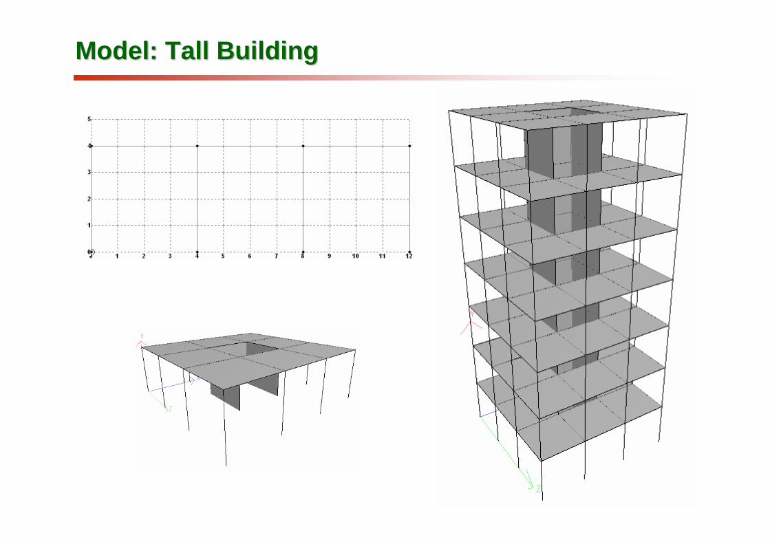
Use Reference Point for Beta angle generation Use Reference Point for Beta angle generation
Not use Use

MirrorMirror

RotateRotate

Model: StadiumModel: Stadium
z
x
x = 20, z = 0
10 m
40 m
40 mOrigin

Model: 3D RoofModel: 3D Roof
Geometry | Move

Insert Node or Split BeamInsert Node or Split Beam

Cut SectionCut Section
Geometry | RenumberGeometry | Renumber

Example: Cut section & RenumberExample: Cut section & Renumber

Model: Commercial SignModel: Commercial Sign
42
1
Z
X
Z
X
3
Z
X
Z
X
42
1
Z
X
Z
X
3
Z
X
Z
X

Mongkol JIRAVACHARADET
S U R A N A R E E INSTITUTE OF ENGINEERING
UNIVERSITY OF TECHNOLOGY SCHOOL OF CIVIL ENGINEERING
STAAD.ProSTAAD.Pro TrainingTraining
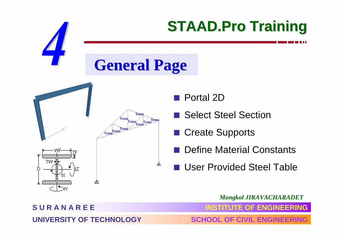
� Portal 2D
� Select Steel Section
� Create Supports
� Define Material Constants
� User Provided Steel Table
General PageGeneral Page

Mongkol JIRAVACHARADET
S U R A N A R E E INSTITUTE OF ENGINEERING
UNIVERSITY OF TECHNOLOGY SCHOOL OF CIVIL ENGINEERING
STAAD.ProSTAAD.Pro TrainingTraining
� Create Primary Load
� Member Load / Nodal Load
� Load Combinations
� Wind Load
� Seismic Load
LoadingsLoadings

Create Primary LoadCreate Primary Load
General | Load

Nodal Load & Member LoadNodal Load & Member Load
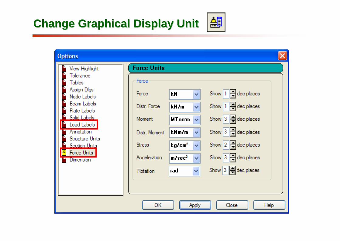
Change Graphical Display UnitChange Graphical Display Unit
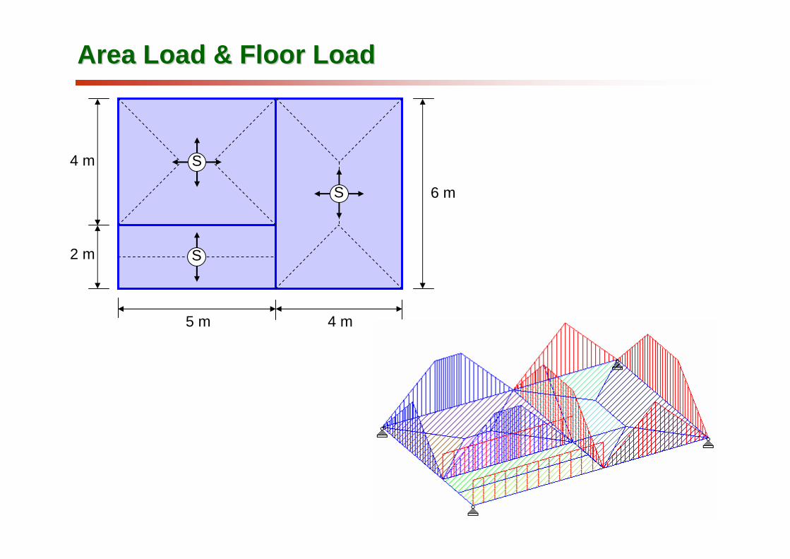
Area Load & Floor LoadArea Load & Floor Load
5 m 4 m
6 m
4 m
2 m S
S
S

ASCE ASCE –– 7 Wind Load Generation7 Wind Load Generation

����������� �
��������� �

UBC Seismic Load GenerationUBC Seismic Load Generation

Mongkol JIRAVACHARADET
S U R A N A R E E INSTITUTE OF ENGINEERING
UNIVERSITY OF TECHNOLOGY SCHOOL OF CIVIL ENGINEERING
STAAD.ProSTAAD.Pro TrainingTraining
� Analysis/Print Commands
� Run Analysis
� View Output File
� Node Displacement
� Force Diagrams
� Local Coordinate System
Analysis & PostAnalysis & Post--ProcessingProcessing

Analysis/Print CommandsAnalysis/Print Commands

Run AnalysisRun Analysis ……

Member End ForcesMember End Forces
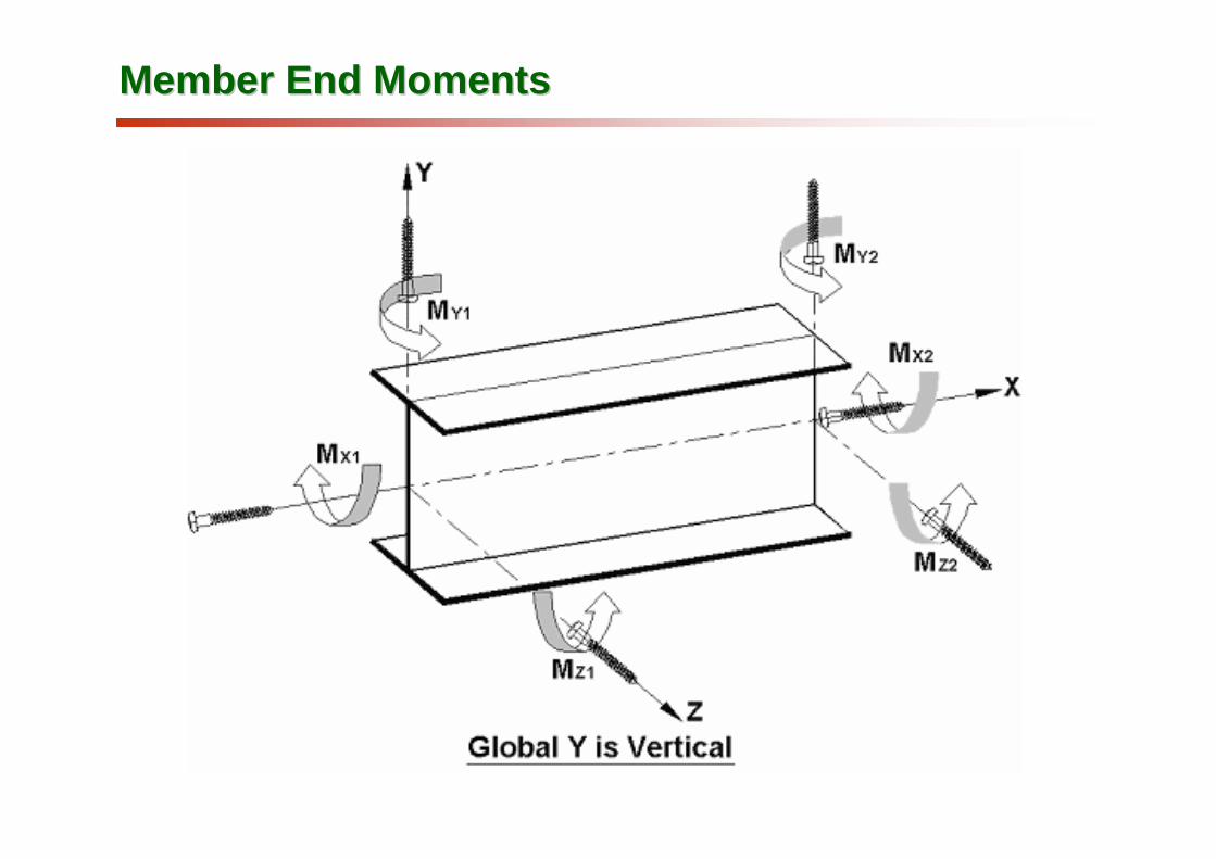
Member End MomentsMember End Moments
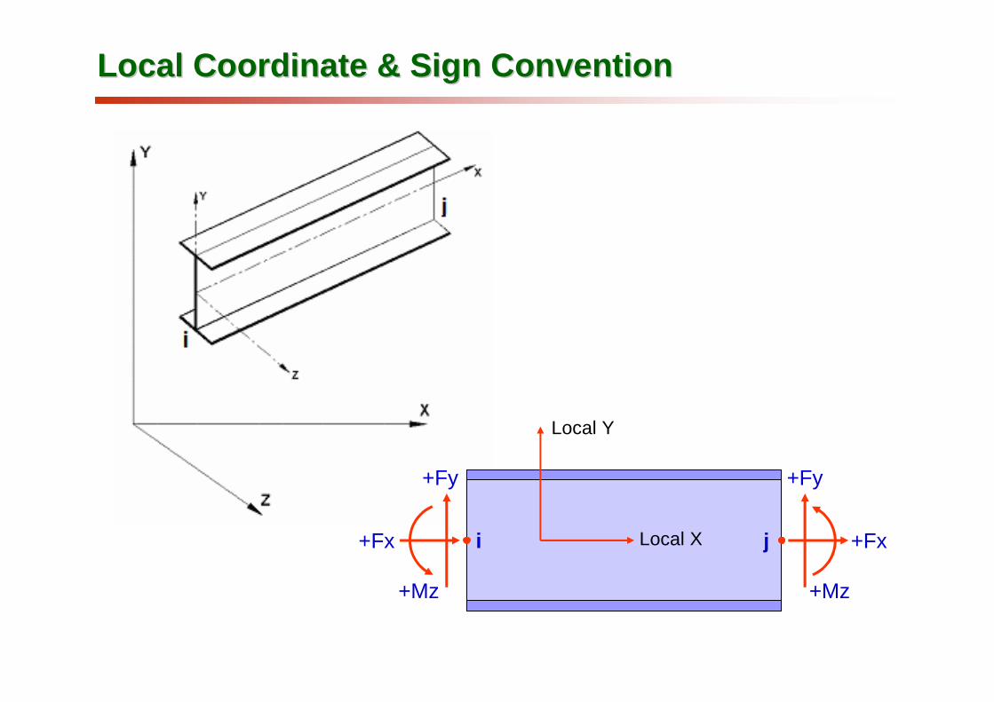
Local Coordinate & Sign ConventionLocal Coordinate & Sign Convention
Local Y
Local Xi j+Fx
+Fy
+Mz
+Fx
+Fy
+Mz

Force DiagramsForce Diagrams
Axial: FX : A positive value is compression, and negative tension.
Shear: FY : A positive value is shear in the positive y-direction, and negative in the negative y-direction.

MZ : A positive moment will cause tension at the top
of the member. Conversely, a negative moment will
cause tension at the bottom of the member.
Force DiagramsForce Diagrams
Bending Moment :
- Mz
+ Mz

Truss 2DTruss 2D
1 m
100
kg 200
kg
200
kg
200
kg
200
kg
200
kg
200
kg
200
kg
200
kg
200
kg
100
kg
2 m
10 @ 1 m = 10 m
1 m
100
kg 200
kg
200
kg
200
kg
200
kg
200
kg
200
kg
200
kg
200
kg
200
kg
100
kg
2 m
10 @ 1 m = 10 m