Embed Size (px)
Citation preview

Geophysical Detection of
Mineral Systems: The
Importance of Deep
Penetrating Geophysical
Methods
Mike Dentith

MINERAL SYSTEMS
Geophysical exploration strategy at the
terrain to prospect scale
Mapping
Direct
Detection
Stratigraphic
Contacts
Host
Lithotype Ore
Minerals
Gangue
Minerals
Alteration
Zone Structure
Komatiite-hosted
NiS
Primary
Diamonds Graphite/U VMS Epithermal
Au Orogenic
Au
‘The Bump’ ‘The Map’

MINERAL SYSTEMS A mineral system suggests a whole
new set of targets!
• Source-pathway-physical throttle-
chemical scrubber
Source: Witherly (2014)

DEEP GEOPHYSICS
Mineral systems processes occur on a scale
of 100s to 1000s of km3
• Need geographically widespread datasets
• Scale is such that these are likely to come from
Government
Need to image source/pathways at kms to
mantle depths
(Source: Groves and Bierlein (2007)

DEEP GEOPHYSICS
Potential mineral system ‘targets’ in the
crust and mantle - sources • Metasomatised mantle
Depleted, re-fertilized etc
• Major magma chambers
or fluid reservoirs
• Zones of crustal
underplating Rifting related
Mafic intrusions
Source: Griffin et al., 2013
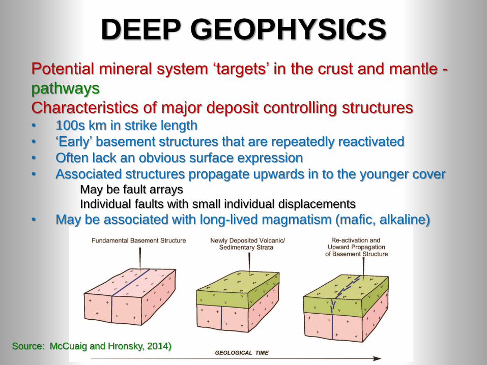
DEEP GEOPHYSICS Potential mineral system ‘targets’ in the crust and mantle -
pathways
Characteristics of major deposit controlling structures • 100s km in strike length
• ‘Early’ basement structures that are repeatedly reactivated
• Often lack an obvious surface expression
• Associated structures propagate upwards in to the younger cover May be fault arrays
Individual faults with small individual displacements
• May be associated with long-lived magmatism (mafic, alkaline)
Source: McCuaig and Hronsky, 2014)

DEEP GEOPHYSICS Pathways • Major structures seen as linears in regional datasets
Need depth data to determine how structures link and
which reach the mantle
Useful to define two classes The response is controlled by a combination of
physical property contrast and the volume of the
material representing the contrast (most cases)
‘Internal’ fault zones are harder to see than ‘interface’
faults
Internal
Fault
(comprises
the contrast)
Interface
Fault
(juxtaposition of
contrasts)
Moho
Block 1 Block 2

DEEP GEOPHYSICS
Source: Grauch et al, 2003
Geophysical options?
• Magnetotellurics (MT)
• Active seismic methods
• Passive seismic methods
• (Gravity and magnetics)
• (Heatflow, DEMS/satellite
remote sensing)
How can these
‘academic’ tools be best
utilised in exploration?

MAGNETOTELLURICS
Deep penetrating
frequency-domain EM
technique • Developed in 1940s
• Can penetrate well in to the
mantle
Passive source • Cheap
Well established ‘academic’
geophysics tool

MAGNETOTELLURICS
Major problem is the lack of understanding
of causes of conductivity variations in deep
Earth – conductive lower crust • Sulphide and oxide phases, graphite, saline
fluids (upper crust)
• Temperature (younger regions)
• Hydration (mantle) Indicative of mantle melting etc, i.e. source areas
Interpretation is exercise in geological
pattern recognition

When it works can provide apparently very
useful results – southern Yilgarn Craton,
Western Australia • Major faults – both interface and internal
• Mantle source zone?
MAGNETOTELLURICS

MAGNETOTELLURICS
When it works can provide apparently very
useful results – Capricorn Orogen, Western
Australia • Cratonic margins beneath younger cover

MAGNETOTELLURICS
When it works can provide apparently very
useful results – Capricorn Orogen, Western
Australia • Cratonic margins beneath younger cover

MAGNETOTELLURICS
A comparatively cheap method of
imaging very deep • Unsure of sources of conductivity
variations
• Images major faults and other tectonic
features – fluid pathways
• Evidence that it can help identify fluid
source and reservoir zones too
Source: Blewitt et al. (2011)
De
pth
(km
) 25
0
75
50
100

SEISMIC REFLECTION
Deep (whole crust) seismic reflection data
• Deeper, lower frequency version of petroleum
seismic surveys
• Several countries have significant amounts of
data
Advantages • Highest resolution type of
geophysics
• Map structure and
stratigraphy in crust
and upper mantle
Source: http://www.ga.gov.au/about/what-we-
do/projects/minerals/current/seismic

SEISMIC REFLECTION
Disadvantages • Very expensive
• Only practical to record in 2D
Sideswipe
Crooked lines
• Poor velocity information High velocities
• Hard to migrate Affects geometric relationships
• ¼ wavelength and Fresnel zones are large in
lower crust Wavelengths are hundreds of metres

SEISMIC REFLECTION
Example – Capricorn Orogen, Western
Australia

SEISMIC REFLECTION
Which of the major faults reach the mantle?
Where are the major ‘terrane’ boundaries?

SEISMIC REFLECTION
Which of the major faults reach the
mantle?
Where are the major ‘terrane’ boundaries? • Spatial association with hydrothermal deposit
SEISMIC REFLECTION
Too expensive to be a greenfields
exploration method
Need to consider cheaper alternatives • Wide-angle/refraction surveys
• Passive seismic methods
• Using these methods to produce ‘reflection’
equivalent products (key research objective)
Probably best used together • Extrapolate away from the reflection profiles
• Also provide complementary information

PASSIVE SEISMIC METHODS
Advantages • Do not require expensive artificial sources
Drilling of shot holes
Disadvantages • Lack resolution
• Long deployment times
Weeks, months, years
Options • Ambient noise methods
• Teleseismic methods Receiver functions, body wave tomography

TELESEISMIC METHODS Receiver functions • Based on the modification of the teleseismic
wavefield as it passes through the crust
(conversions, multiple reflections)
• Receiver function is the velocity structure
beneath the recording station
• Produces 1D velocity-depth function
Source: http://eqseis.geosc.psu.edu/~cammon/HTML/RftnDocs/rftn01.html

TELESEISMIC METHODS Receiver functions • Can be inverted to produce a 1D
velocity function
• More recent work has concentrated on higher
resolution arrays and common conversion point
(CCP) processing
• Can produce a ‘low resolution’ seismic reflection-like
section based on major velocity variations
Source: Schulte-Pelkum et al. (2005)

TELESEISMIC METHODS High resolution receiver function study in the
Capricorn Orogen

PASSIVE SEISMIC METHODS
Potential role in mapping major geological
boundaries • Interface faults at craton margins
• Methods etc in existence
Emerging role for receiver function-based
surveys • Map major boundaries (interface faults)
• New methods map major structures (internal
faults)
• Cheaper, lower resolution surveys to
complement seismic reflection surveys

DEEP GEOPHYSICS & MINERAL
SYSTEMS There are plenty of useful and established
deep geophysical tools available
And there are potentially some exciting
new ones over the horizon
We need to combine ‘interface’ and
‘internal’ fault imaging methods • Deep seismic reflection data can provide a
reference point but need other methods to
get good spatial coverage at realistic cost
• MT, receiver function, and ambient noise
tomography?

Implications for mineral system
analysis • Mapping lithospheric architecture/pathways
is achievable with existing ‘solid earth’
geophysical methods
• There is inadequate understanding of
causes of variations in petrophysical
properties
Alteration associated with fluid flow and
reservoirs
Particular problem with understanding
electrical properties
DEEP GEOPHYSICS & MINERAL
SYSTEMS

Implications for mineral system
analysis • Governments should think about collecting
deep geophysical datasets Olympic Dam Cu-U-
Au-Ag-REE Iron
Oxide Copper Gold
Deposit
DEEP GEOPHYSICS & MINERAL
SYSTEMS