Embed Size (px)
Citation preview

GEOPROTEK Solar Technology
Installation Guide

GEOPROTEK Solar Technology
Installation Guide 2
Table of Contents 1 Notes on this Manual ................................................................................................................ 3 2 Conventions ............................................................................................................................... 4 3 Safety Instructions .................................................................................................................... 5
3.1 Appropriate Usage ........................................................................................................ 5 4 Unpacking .................................................................................................................................. 6
4.1 Scope of Delivery........................................................................................................... 6 4.2 Check for Transport Damage....................................................................................... 6 4.3 Identification of the GS INVERTER........................................................................... 7
5 Mounting.................................................................................................................................... 8 5.1 Important Safety Information ........................................................................................... 8 5.2 Selecting the Mounting Location ....................................................................................... 9
5.2.1 Dimensions and Weight ........................................................................................... 9 5.2.2 Ambient Conditions ................................................................................................. 9 5.2.3 Safety Distances...................................................................................................... 10 5.2.4 Position .................................................................................................................... 10
5.3 Mounting Instructions ...................................................................................................... 11 5.3.1 Mounting with Wall Bracket................................................................................. 11
6 Electrical Connection.............................................................................................................. 15 6.1 Overview of Connection Area .......................................................................................... 15 6.2 Connecting the Public Grid (AC side)............................................................................. 16 6.3 Connecting the PV Array (DC side) ................................................................................ 18
The PV Array design and installation must comply with the requirements of AS/NZS 5033................................................................................................................................... 18 6.3.1 One string connection for GS-1500/GS-2000/GS-3000....................................... 18 6.3.2 Three string connection for GS-4000 ................................................................... 19
6.4 Installing a Communication Module............................................................................... 20 6.5 Commissioning the PV Array System ............................................................................. 21 6.6 Removal ............................................................................................................................. 22
7 Inverter Display....................................................................................................................... 23 7.1 Normal Mode............................................................................................................... 23 7.2 Fault Mode................................................................................................................... 23 7.3 Information Display .................................................................................................... 23 7.4 Display Setting............................................................................................................. 25
8 Messages................................................................................................................................... 26 8.1 Error Messages and troubleshooting ........................................................................ 26 8.2 Update Messages ......................................................................................................... 28
9 Specification............................................................................................................................. 29

GEOPROTEK Solar Technology
Installation Guide 3
1 Notes on this Manual Congratulations on purchasing GS series Grid PV-Inverter. GS INVERTER converts the direct current from your solar system into grid-compliant alternating current. GS INVERTER is a highly reliable product due to innovative design and perfect quality control. This user manual describes the installation, operation, safety, and commissioning of GEOPROTEK Solar Technology Inverters. Be sure to read this manual carefully before enjoying this product. If you encounter any problem during installing or using this inverter, please check this manual first before contacting with your local dealer or representative. Most of the problems you encountered will be solved according to the instruction inside.

GEOPROTEK Solar Technology
Installation Guide 4
2 Conventions The following conventions are used in this manual: This icon denotes a tip, which alerts you to advisory information. This icon denotes a note, which alerts you to important information.
This icon denotes a caution, which advises you of precautions to take to avoid injury, data loss, or a system crash.
GEOPROTEK Solar Technology
Installation Guide 5
3 Safety Instructions The following section contains important safety information that you must follow when installing and using the product.
3.1 Appropriate Usage
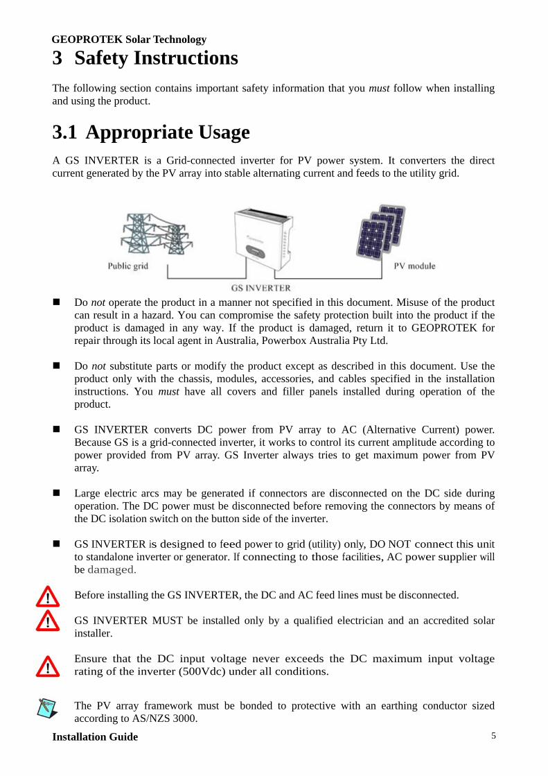
A GS INVERTER is a Grid-connected inverter for PV power system. It converters the direct current generated by the PV array into stable alternating current and feeds to the utility grid.
Do not operate the product in a manner not specified in this document. Misuse of the product
can result in a hazard. You can compromise the safety protection built into the product if the product is damaged in any way. If the product is damaged, return it to GEOPROTEK for repair through its local agent in Australia, Powerbox Australia Pty Ltd.
Do not substitute parts or modify the product except as described in this document. Use the
product only with the chassis, modules, accessories, and cables specified in the installation instructions. You must have all covers and filler panels installed during operation of the product.
GS INVERTER converts DC power from PV array to AC (Alternative Current) power.
Because GS is a grid-connected inverter, it works to control its current amplitude according to power provided from PV array. GS Inverter always tries to get maximum power from PV array.
Large electric arcs may be generated if connectors are disconnected on the DC side during
operation. The DC power must be disconnected before removing the connectors by means of the DC isolation switch on the button side of the inverter.
GS INVERTER is designed to feed power to grid (utility) only, DO NOT connect this unit
to standalone inverter or generator. If connecting to those facilities, AC power supplier will be damaged.
Before installing the GS INVERTER, the DC and AC feed lines must be disconnected. GS INVERTER MUST be installed only by a qualified electrician and an accredited solar
installer. Ensure that the DC input voltage never exceeds the DC maximum input voltage
rating of the inverter (500Vdc) under all conditions.
The PV array framework must be bonded to protective with an earthing conductor sized according to AS/NZS 3000.

GEOPROTEK Solar Technology
Installation Guide 6
4 Unpacking
4.1 Scope of Delivery
Object Description A GS Inverter B Wall mounting bracket C User manual D DC connector socket (Tyco)* E AC connector socket with rubber bushing F Four screws for fixing wall mounting bracket
Two safety lock screws for fixing two sides of the inverter
4.2 Check for Transport Damage Please take out the unit from packaging box carefully. Check the GS INVERTER for visible external damage, such as cracks in the housing or display. Please contact your local dealer if you find any damage.
GEOPROTEK Solar Technology
Installation Guide 7
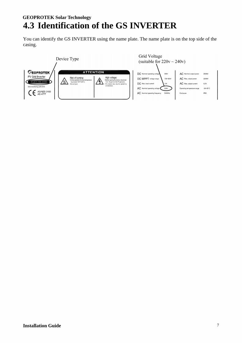
4.3 Identification of the GS INVERTER You can identify the GS INVERTER using the name plate. The name plate is on the top side of the casing.

GEOPROTEK Solar Technology
Installation Guide 8
5 Mounting 5.1 Important Safety Information IMPORTANT: Isolate this inverter from both the PV array and mains grid BEFORE
commencing any installation or service work. A licensed electrician and accredited solar installer must install the entire system, including
the PV array and associated wiring. The entire generating system MUST be designed and installed in accordance with
AS/NZS3000, AS4777, AS/NZS5033, and any requirements of the local electricity utility. Particular attention should be paid to the design of and selection of components for the following: PV and mains disconnection devices. PV and mains fault current protection. PV cable selection, current rating and insulation. PV system and equipment earthing including earth of PV array frames. PV module equipment class and required approvals.
Protection from lightning should be provided per AS/NZS1768. This inverter is classified as a “non-isolated PCU” per AS/NZS5033. This inverter is a non-isolated (transformerless) grid-feeding inverter. LV mains voltage will
be present between the PV array and earth when the inverter is operating. The PV array framework must be bonded to earth with an earthing conductor sized according
to AS/NZS3000. When connecting and disconnecting the PV array to this inverter, protective earth must
remain connected. The grid (AC utility) connector must be connected first and disconnected last. This connector is a permanently- latching type requiring use of a tool for removal to avoid inadvertent disconnection.
NEVER connect an AC generator, wind generator or battery bank to the input of the inverter. Severe damage will result. Only PV panels may supply this inverter.
Hazardous voltages can be present inside this inverter even after disconnection. Removal of the cover will invalidate the warranty and may result in injury.
Generally, this inverter is not suitable for use with thin film PV panels. Check with your panel manufacturer that the PV panels can be used with a non- isolated (transformerless) grid feeding inverter.
This inverter has an integral GFCI (ground fault current interrupter) which detects ground fault current or residual current in the system ground. This circuit disconnects the inverter from the grid if this current is greater than30mA. This circuit provides protection from a ground fault in the PV array or accidental contact with PV array circuitry.
Warning:If either of the PV (DC) input supply cords or the AC mains cord are damaged, they shall be replaced by the manufacturer, their service agent or a similarly qualified person in order to avoid hazards.

GEOPROTEK Solar Technology
Installation Guide 9
5.2 Selecting the Mounting Location
Do not mount the GS INVERTER in an explosive atmosphere or where there may be flammable gases or fumes. If you must operate the product in such an environment, it must be in a suitably rated enclosure. Do not exceed the maximum ratings for the GS INVERTER. Do not install wiring while the product is live with electrical power. Do not remove or add connector blocks when power is connected to the system. Avoid contact between your body and the connector block. Remove power from feed lines before connecting them to or disconnecting them from GS INVERTER.
5.2.1 Dimensions and Weight
5.2.2 Ambient Conditions The GS INVERTER housing meets the requirements of protection type IP65 and is suitable
for outdoor and indoor installation. Protection rating IP65 is only met if the enclosed AC connector the Tyco DC connectors are used.
In order to maximize the energy yield it is important to position the inverter correctly. The lower the ambient temperature, the more efficiently the inverter will operate. The ambient temperature of installation must be in the range -20°C~+55°C.
Do not expose the GS INVERTER to the sun directly, in order to avoid power reduction due to high temperature. A protected installation location, for example under a canopy or a solar module, would be an advantage. The device should also be protected from splashing, for example rainwater dripping off roof or module edges.
The inverter must be mounted on a solid surface. If the GS INVERTER is installed inside a building, the space should be well ventilated. In external installations direct sunlight should be avoided. Due to noise emission it is advisable to avoid installation in living areas. The installation must be done by a qualified solar installer. Please ensure GS INVERTER connection to grid is approved by the utility company. And
the grid to be connected is 230V system.
GEOPROTEK Solar Technology
Installation Guide 10
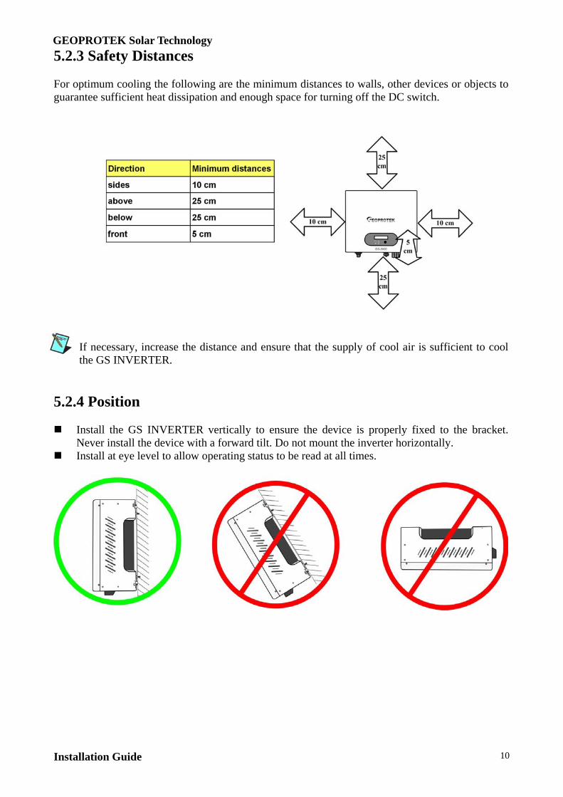
5.2.3 Safety Distances For optimum cooling the following are the minimum distances to walls, other devices or objects to guarantee sufficient heat dissipation and enough space for turning off the DC switch.
If necessary, increase the distance and ensure that the supply of cool air is sufficient to cool the GS INVERTER.
5.2.4 Position Install the GS INVERTER vertically to ensure the device is properly fixed to the bracket.
Never install the device with a forward tilt. Do not mount the inverter horizontally. Install at eye level to allow operating status to be read at all times.

GEOPROTEK Solar Technology
Installation Guide 11
5.3 Mounting Instructions
5.3.1 Mounting with Wall Bracket For GS 1500/2000/3000:

GEOPROTEK Solar Technology
Installation Guide 12
For GS 4000:
GEOPROTEK Solar Technology
Installation Guide 13
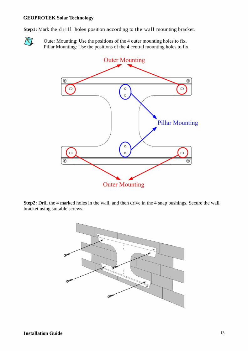
Step1: Mark the d r i l l holes position according to the wall mounting bracket.
Mark Outer Mounting: Use the positions of the 4 outer mounting holes to fix.
Pillar Mounting: Use the positions of the 4 central mounting holes to fix.
Step2: Drill the 4 marked holes in the wall, and then drive in the 4 snap bushings. Secure the wall bracket using suitable screws.
GEOPROTEK Solar Technology
Installation Guide 14
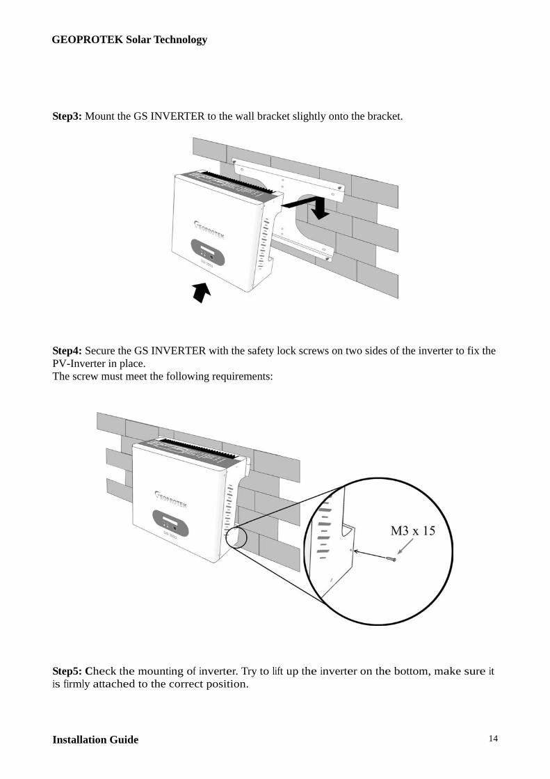
Step3: Mount the GS INVERTER to the wall bracket slightly onto the bracket.
Step4: Secure the GS INVERTER with the safety lock screws on two sides of the inverter to fix the PV-Inverter in place. The screw must meet the following requirements:
Step5: Check the mounting of inverter. Try to lift up the inverter on the bottom, make sure it is firmly attached to the correct position.
GEOPROTEK Solar Technology
Installation Guide 15
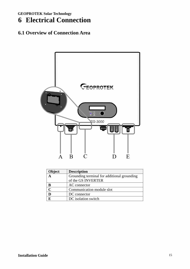
6 Electrical Connection 6.1 Overview of Connection Area
Object Description A Grounding terminal for additional grounding
of the GS INVERTER B AC connector C Communication module slot D DC connector E DC isolation switch
GEOPROTEK Solar Technology
Installation Guide 16
6.2 Connecting the Public Grid (AC side)
Connections to the main switchboard or a distribution board must comply with the appropriate requirements of AS/NZS 3000 and AS/NZS 4777.1. In all installations, the following items must be provided:
Solar supply main switch and overcurrent protection. This is located in the main switchboard or distribution board to which the inverter is to be connected.
AC isolation device. If the inverter is more than 3 metres away from the main switchboard or distribution board, or if the inverter is not in clear view of this board, as AC isolation device must be provided adjacent to the inverter. This device must be rated to interrupt the maximum AC output current from the inverter.
Step1: Cable Design
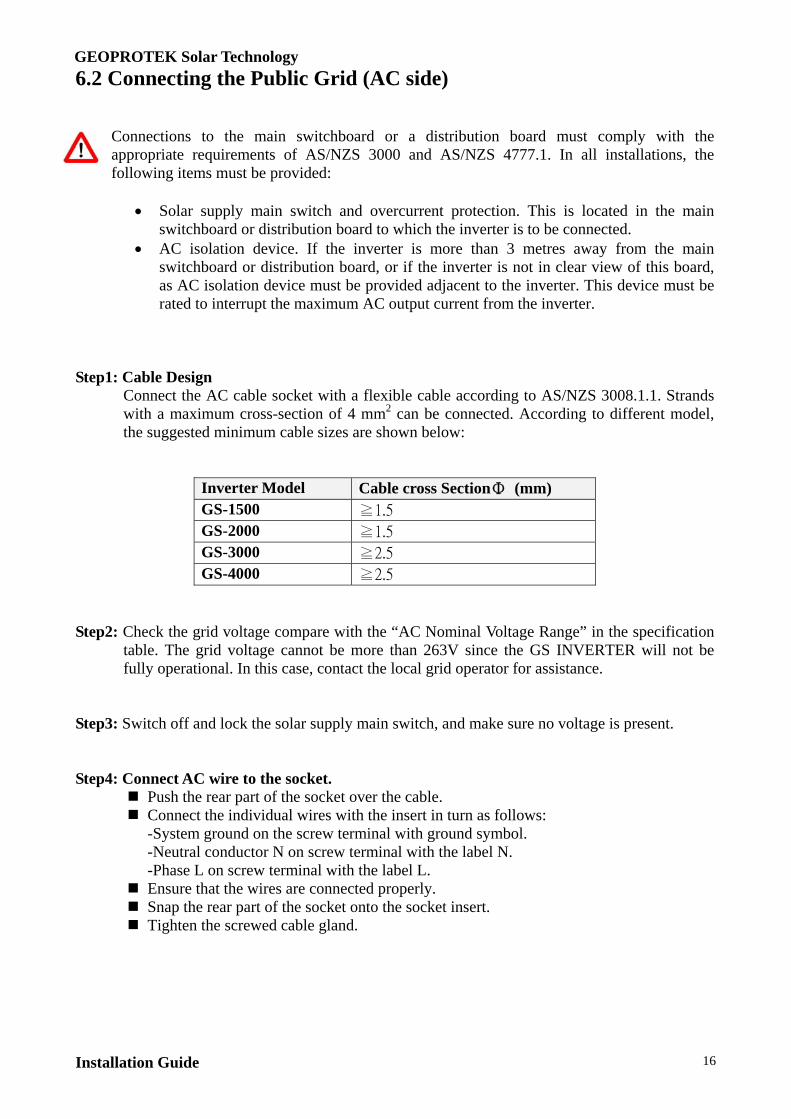
Connect the AC cable socket with a flexible cable according to AS/NZS 3008.1.1. Strands with a maximum cross-section of 4 mm2 can be connected. According to different model, the suggested minimum cable sizes are shown below:
Inverter Model Cable cross SectionΦ (mm) GS-1500 ≧1.5 GS-2000 ≧1.5 GS-3000 ≧2.5 GS-4000 ≧2.5
Step2: Check the grid voltage compare with the “AC Nominal Voltage Range” in the specification
table. The grid voltage cannot be more than 263V since the GS INVERTER will not be fully operational. In this case, contact the local grid operator for assistance.
Step3: Switch off and lock the solar supply main switch, and make sure no voltage is present.
Step4: Connect AC wire to the socket. Push the rear part of the socket over the cable. Connect the individual wires with the insert in turn as follows:
-System ground on the screw terminal with ground symbol. -Neutral conductor N on screw terminal with the label N. -Phase L on screw terminal with the label L. Ensure that the wires are connected properly. Snap the rear part of the socket onto the socket insert. Tighten the screwed cable gland.

GEOPROTEK Solar Technology
Installation Guide 17
Do not switch on the line circuit breaker until the PV array (DC side) has been connected.
If a second protective earth connection is required, you can also ground the GS INVERTER with an additional protective earth ground on the connection terminal of the housing as shown below:
You can ground multiple GS INVERTERS as shown below:
GEOPROTEK Solar Technology
Installation Guide 18
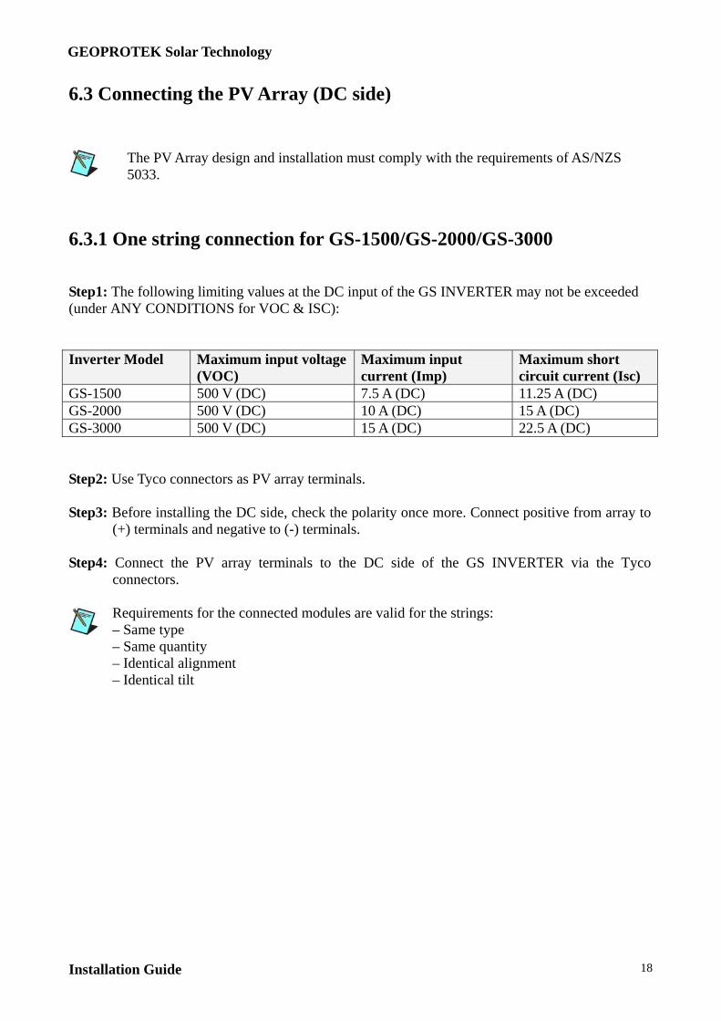
6.3 Connecting the PV Array (DC side)
The PV Array design and installation must comply with the requirements of AS/NZS 5033.
6.3.1 One string connection for GS-1500/GS-2000/GS-3000 Step1: The following limiting values at the DC input of the GS INVERTER may not be exceeded (under ANY CONDITIONS for VOC & ISC): Inverter Model Maximum input voltage
(VOC) Maximum input current (Imp)
Maximum short circuit current (Isc)
GS-1500 500 V (DC) 7.5 A (DC) 11.25 A (DC) GS-2000 500 V (DC) 10 A (DC) 15 A (DC) GS-3000 500 V (DC) 15 A (DC) 22.5 A (DC) Step2: Use Tyco connectors as PV array terminals. Step3: Before installing the DC side, check the polarity once more. Connect positive from array to
(+) terminals and negative to (-) terminals. Step4: Connect the PV array terminals to the DC side of the GS INVERTER via the Tyco
connectors.
Requirements for the connected modules are valid for the strings: – Same type – Same quantity – Identical alignment – Identical tilt
GEOPROTEK Solar Technology
Installation Guide 19
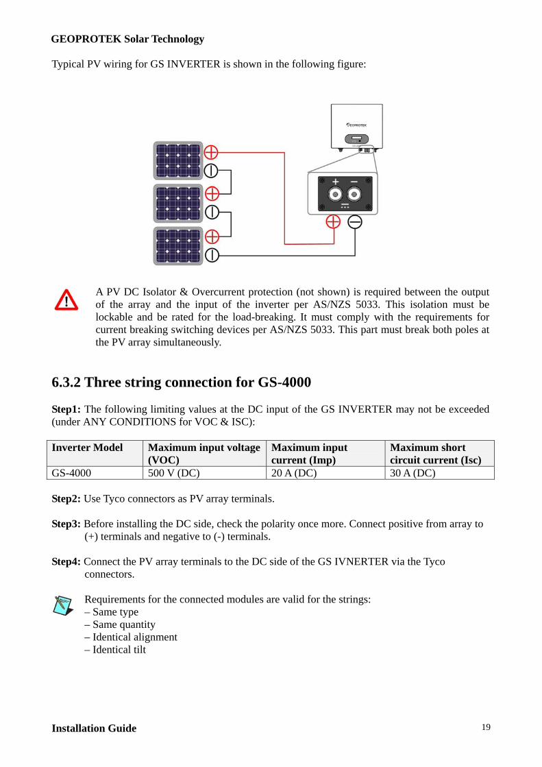
Typical PV wiring for GS INVERTER is shown in the following figure:
A PV DC Isolator & Overcurrent protection (not shown) is required between the output of the array and the input of the inverter per AS/NZS 5033. This isolation must be lockable and be rated for the load-breaking. It must comply with the requirements for current breaking switching devices per AS/NZS 5033. This part must break both poles at the PV array simultaneously.
6.3.2 Three string connection for GS-4000 Step1: The following limiting values at the DC input of the GS INVERTER may not be exceeded (under ANY CONDITIONS for VOC & ISC): Inverter Model Maximum input voltage
(VOC) Maximum input current (Imp)
Maximum short circuit current (Isc)
GS-4000 500 V (DC) 20 A (DC) 30 A (DC) Step2: Use Tyco connectors as PV array terminals. Step3: Before installing the DC side, check the polarity once more. Connect positive from array to
(+) terminals and negative to (-) terminals. Step4: Connect the PV array terminals to the DC side of the GS IVNERTER via the Tyco
connectors.
Requirements for the connected modules are valid for the strings: – Same type – Same quantity – Identical alignment – Identical tilt
GEOPROTEK Solar Technology
Installation Guide 20
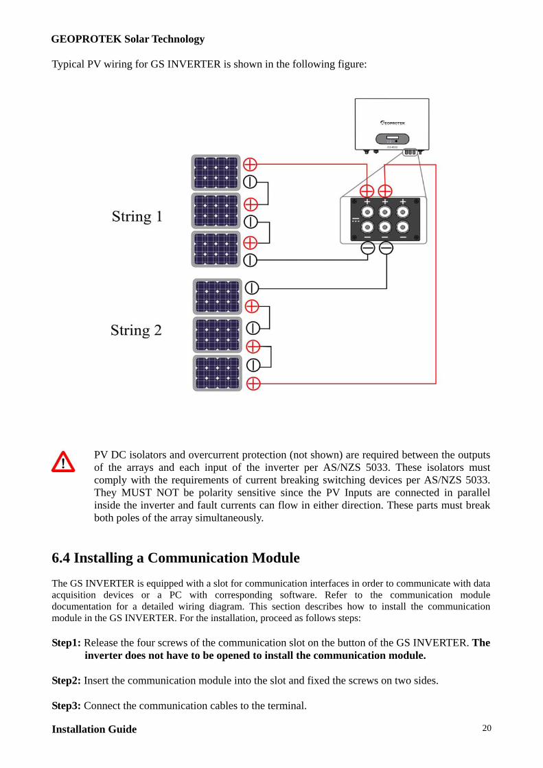
Typical PV wiring for GS INVERTER is shown in the following figure:
PV DC isolators and overcurrent protection (not shown) are required between the outputs of the arrays and each input of the inverter per AS/NZS 5033. These isolators must comply with the requirements of current breaking switching devices per AS/NZS 5033. They MUST NOT be polarity sensitive since the PV Inputs are connected in parallel inside the inverter and fault currents can flow in either direction. These parts must break both poles of the array simultaneously.
6.4 Installing a Communication Module The GS INVERTER is equipped with a slot for communication interfaces in order to communicate with data acquisition devices or a PC with corresponding software. Refer to the communication module documentation for a detailed wiring diagram. This section describes how to install the communication module in the GS INVERTER. For the installation, proceed as follows steps: Step1: Release the four screws of the communication slot on the button of the GS INVERTER. The
inverter does not have to be opened to install the communication module. Step2: Insert the communication module into the slot and fixed the screws on two sides. Step3: Connect the communication cables to the terminal.
GEOPROTEK Solar Technology
Installation Guide 21
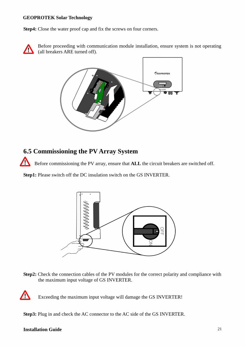
Step4: Close the water proof cap and fix the screws on four corners.
Before proceeding with communication module installation, ensure system is not operating (all breakers ARE turned off).
6.5 Commissioning the PV Array System
Before commissioning the PV array, ensure that ALL the circuit breakers are switched off. Step1: Please switch off the DC insulation switch on the GS INVERTER.
Step2: Check the connection cables of the PV modules for the correct polarity and compliance with
the maximum input voltage of GS INVERTER.
Exceeding the maximum input voltage will damage the GS INVERTER!
Step3: Plug in and check the AC connector to the AC side of the GS INVERTER.
GEOPROTEK Solar Technology
Installation Guide 22
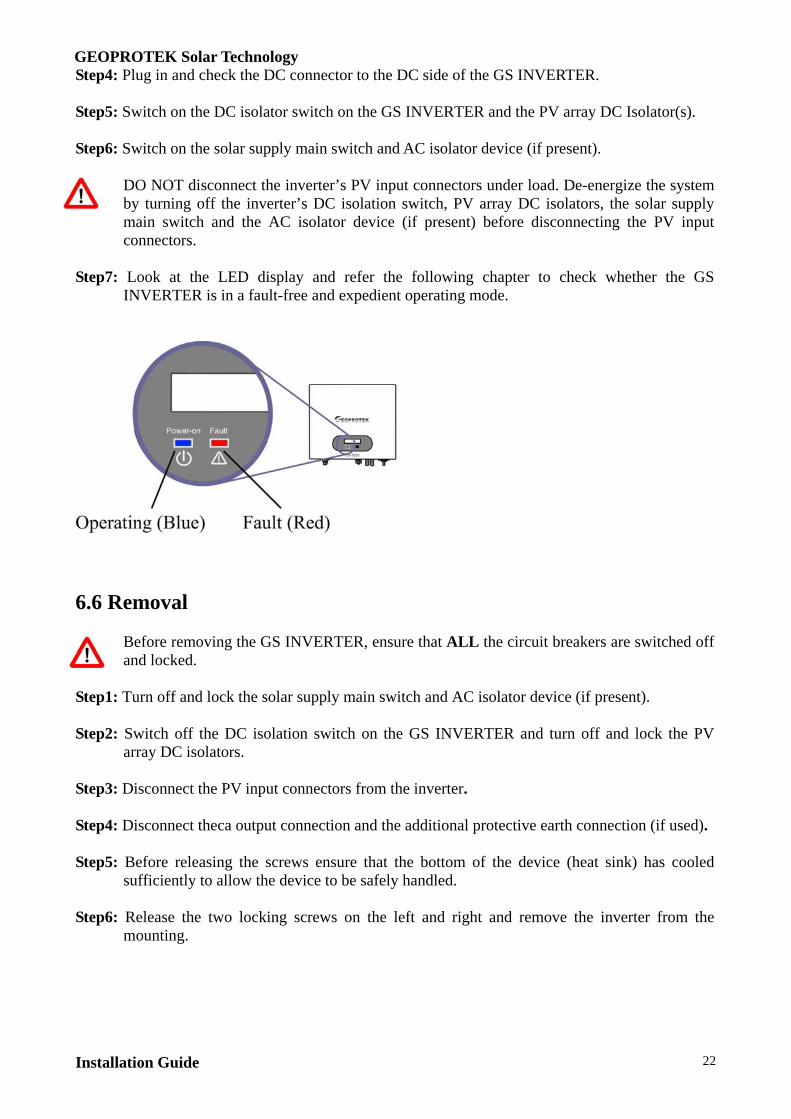
Step4: Plug in and check the DC connector to the DC side of the GS INVERTER. Step5: Switch on the DC isolator switch on the GS INVERTER and the PV array DC Isolator(s). Step6: Switch on the solar supply main switch and AC isolator device (if present).
DO NOT disconnect the inverter’s PV input connectors under load. De-energize the system by turning off the inverter’s DC isolation switch, PV array DC isolators, the solar supply main switch and the AC isolator device (if present) before disconnecting the PV input connectors.
Step7: Look at the LED display and refer the following chapter to check whether the GS
INVERTER is in a fault-free and expedient operating mode.
6.6 Removal
Before removing the GS INVERTER, ensure that ALL the circuit breakers are switched off and locked.
Step1: Turn off and lock the solar supply main switch and AC isolator device (if present). Step2: Switch off the DC isolation switch on the GS INVERTER and turn off and lock the PV
array DC isolators. Step3: Disconnect the PV input connectors from the inverter. Step4: Disconnect theca output connection and the additional protective earth connection (if used). Step5: Before releasing the screws ensure that the bottom of the device (heat sink) has cooled
sufficiently to allow the device to be safely handled. Step6: Release the two locking screws on the left and right and remove the inverter from the
mounting.

GEOPROTEK Solar Technology
Installation Guide 23
7 Inverter Display 7.1 Normal Mode With a fault-free grid connection to the GS INVERTER, it will operate in normal mode and the ‘Power-on’ LED will be in lighted up in BLUE. Then it will go into the following steps: 1. As the PV array is greater than 100V, the GS
IVNERTER is waiting to feed to the grid and shows ‘INV Waiting’.
2. When PV array is greater than 150V, GS INVERTER is
checking the feeding conditions and shows ‘Testing’ counting down from 60 to 0.
3. After checking the grid and the internal status, the GS
INVERTER will start to feed power to the grid and shows ‘Working Mode’. Otherwise it will go into the fault mode.
As the PV array is greater than 90V and less than 100V, the GS INVERTER is in standby and shows ‘INV Standby’.
7.2 Fault Mode In a fault condition, the GS INVERTER will go into fault mode. The ‘Fault’ LED will be RED and the ‘Power-on’ LED will turn off. According to the message display on the LCD, please check the list in Section 8.1 error message table for troubleshooting.
7.3 Information Display As GS INVERTER operates in working mode, you can press the function button to check the inverter information. The function button cycles through the various system parameters. The LCD will show the following information in sequence: 1. Pressing the function button once during the ‘Working
Mode’ state displays the AC output power. 2. Pressing the function button twice to display the DC
input voltage. 3. Pressing the function button three times displays the DC
input current.

GEOPROTEK Solar Technology
Installation Guide 24
4. Pressing the function button four times displays the AC output voltage.
5. Pressing the function button five times displays the AC
frequency. 6. Pressing the function button six times displays the AC
output current. 7. Pressing the function button seven times displays the
Total AC output energy since commissioning. 8. Pressing the function button eight times displays the
Inverter Rating. 9. Pressing the function button night times displays the
Master CPU version. 10. Pressing the function button ten times displays the Slave
CPU version.
After 5 seconds of inactivity, the LCD will back to the main screen and shows ‘Working Mode’.
If you need to lock the current information display, you can use the following steps to lock and unlock the information display: 1. Press the function button to display the
information you need to lock. 2. Press the function button for 5 seconds, it will
show “Freeze”. 3. The LCD will always show the information you
need to display. 4. If you need to unlock it, please press the
function button for 5 seconds. The LCD will show “Unfreeze” and go back to the main screen.

GEOPROTEK Solar Technology
Installation Guide 25
7.4 Display Setting In the display setting, you can select different language display and adjust the contrast. Please setup by the following steps: Contrast setting procedure: 1. Press the function button for 3 seconds as the LCD in
‘Working Mode’. 2. The LCD shows ‘Setting’ in the screen. 3. Press the function button for 3 seconds to enter the contrast
setting. 4. Press the function button to adjust the contrast from 1 to 5. 5. After finished, press the function button for 3 seconds to
confirm the setting and it will back to “Setting”. Language setting procedure: 1. Press the function button for 3 seconds as the LCD in
‘Working Mode’. 2. The LCD shows ‘Setting’ in the screen. 3. Press the function button for 3 seconds to enter the
language setting. 4. Press the function button to select different language. 5. After finished, press the function button for 3 seconds to
confirm the setting and it will back to “Setting”.
GEOPROTEK Solar Technology
Installation Guide 26
8 Messages
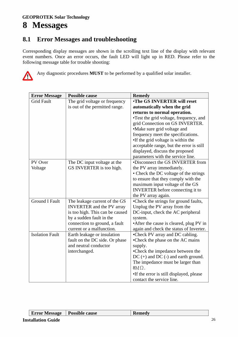
8.1 Error Messages and troubleshooting Corresponding display messages are shown in the scrolling text line of the display with relevant event numbers. Once an error occurs, the fault LED will light up in RED. Please refer to the following message table for trouble shooting:
Any diagnostic procedures MUST to be performed by a qualified solar installer.
Error Message Possible cause Remedy Grid Fault The grid voltage or frequency
is out of the permitted range. •The GS INVERTER will reset automatically when the grid returns to normal operation. •Test the grid voltage, frequency, and grid Connection on GS INVERTER. •Make sure grid voltage and frequency meet the specifications. •If the grid voltage is within the acceptable range, but the error is still displayed, discuss the proposed parameters with the service line.
PV Over Voltage
The DC input voltage at the GS INVERTER is too high.
•Disconnect the GS INVERTER from the PV array immediately. • Check the DC voltage of the strings to ensure that they comply with the maximum input voltage of the GS INVERTER before connecting it to the PV array again.
Ground I Fault The leakage current of the GS INVERTER and the PV array is too high. This can be caused by a sudden fault in the connection to ground, a fault current or a malfunction.
•Check the strings for ground faults, Unplug the PV array from the DC-input, check the AC peripheral system. •After the cause is cleared, plug PV in again and check the status of Inverter.
Isolation Fault Earth leakage or insulation fault on the DC side. Or phase and neutral conductor interchanged.
•Check PV array and DC cabling. •Check the phase on the AC mains supply. •Check the impedance between the DC (+) and DC (-) and earth ground. The impedance must be larger than 8MΩ. •If the error is still displayed, please contact the service line.
Error Message Possible cause Remedy

GEOPROTEK Solar Technology
Installation Guide 27
Over Temperature
The internal temperature of GS INVERTER is too high Insufficient air circulation
•Ensure air can circulate at the side of the GS INVERTER. •improve ventilation around the inverter. •If it is not effective, the temperature sensors fails, please contact the service line.
No Utility Grid is not connected; check the AC connection by multi-meter.
• Check AC installation and grid connection. • Check whether there is a general power failure. • Check breaker between inverter and grid; if it is tripped, DO NOT CLOSE again, replace the inverter.
Impedance Fault The grid impedance at the connection point of the GS INVERTER is too high.
•Observe the error for 30 seconds, check if it works normally. •Check the wires between inverter and grid. Change larger wires if necessary. •If the error is still displayed, please contact the service line for further assistance.
Consistent Fault It may cause by the reading difference between main and redundant controllers.
DC Curr Mismatch
The reading difference of output DC current between main and redundant controllers.
GFCI Mismatch The reading difference of GFCI value current between main and redundant controllers.
Grid V Mismatch
The reading difference of Grid V between main and redundant controllers.
Grid F Mismatch
The reading difference of Grid F between main and redundant controllers.
Grid Z Mismatch
The reading difference of Grid impedance between main and redundant controllers.
Sci Fault Communication error between main and redundant controllers.
CPU Ver Mismatch
The reading difference of firmware version between main and redundant controllers.
•Switch off the DC isolator switch and PV array isolators. •Switch off solar supply main switch.•Disconnect DC (+) and DC (-) from the input for one minute and reconnect it again. •Switch on the solar supply main switch. •Switch on the DC isolator switch and PV Array isolators. •If it does not work, please contact service line.
Error Message Possible cause Remedy

GEOPROTEK Solar Technology
Installation Guide 28
Device Fault It may cause by improper operation of the circuit.
Relay Failure It may cause by the failure of output relay.
DC INJ High It may cause by the DC output injection was too high
Ref 2.5V Fault 2.5V reference voltage inside problem
DC Sensor Fault It may cause by the abnormal of DC output sensor.
GFCI Fault GFCI detection problem EEPROM Fault EEPROM problem DC Bus High It may cause by the voltage of
DC bus was too high. DC Bus Low It may cause by the voltage of
DC bus was too low.
•Switch off the DC isolator switch and PV array isolators. •Switch off solar supply main switch.•Disconnect DC (+) and DC (-) from the input for one minute and reconnect it again. •Switch on the solar supply main switch •Switch on the DC isolator switch and PV Array isolators. •If it does not work, please contact service line
8.2 Update Messages
Corresponding display messages are shown in the LCD display when an firmware update is made.
Update Message Description Master Flash The internal program is updating main
controller CPU through RS-232 interface. Slave Flash The internal program is updating redundant
controller CPU through RS-232 interface.

GEOPROTEK Solar Technology
Installation Guide 29
9 Specification GS-1500 GS-2000
Maximum Input Power 1750W 2340W
DC Maximum Voltage (VOC) 500 VDC
MPPT Voltage Range (Vmp) 150VDC ~ 500VDC ± 5% 150VDC ~ 500VDC ± 5%
DC Maximum Input Current (Imp) 7.5 ADC 10 ADC
Maximum PV Array
Short Circuit Current (ISC)
11.25 ADC 15 ADC
DC Voltage Ripple <10%
Number of String Inputs/ Type 1 (Tyco)
PV Start Voltage 150VDC ± 5% 150VDC ± 5%
AC Nominal Power 1500W 2000W
AC Maximum Output Power 1650W 2200W
AC Maximum Output Current 6.6 A 8.7 A
AC Nominal Voltage 230VAC
AC Voltage Range (firmware setting) 207VAC ~ 263VAC
AC Nominal Frequency 50Hz
AC Frequency Range (firmware
setting) 49.25-50.75 Hz
Power Factor >0.99
Maximum Inverter Efficiency 95% 95%
European Inverter Efficiency 94% 94%
Dimensions: W x H X D (mm) 380 x 300 x 133 380 x 300 x 133
Weight (kg) 14 14
Operating Temperature -25 to 55 ºC
Humidity 0 to 95%, non-condensing
Power Consumption:
standby/night time
<0.1W
Heat Dissipation Convection
DC Switch ON/OFF 20A
O/P current distortion THD<5%, each harmonics<3%
GEOPROTEK Solar Technology
Installation Guide 30
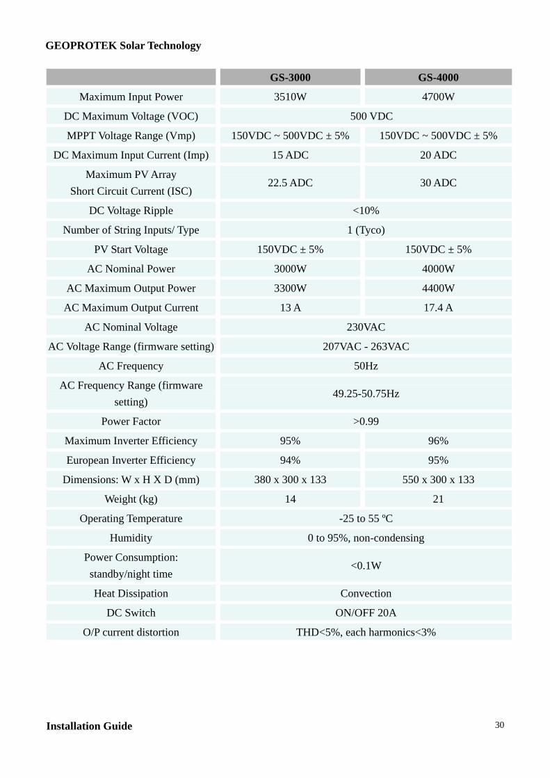
GS-3000 GS-4000
Maximum Input Power 3510W 4700W
DC Maximum Voltage (VOC) 500 VDC
MPPT Voltage Range (Vmp) 150VDC ~ 500VDC ± 5% 150VDC ~ 500VDC ± 5%
DC Maximum Input Current (Imp) 15 ADC 20 ADC
Maximum PV Array
Short Circuit Current (ISC) 22.5 ADC 30 ADC
DC Voltage Ripple <10%
Number of String Inputs/ Type 1 (Tyco)
PV Start Voltage 150VDC ± 5% 150VDC ± 5%
AC Nominal Power 3000W 4000W
AC Maximum Output Power 3300W 4400W
AC Maximum Output Current 13 A 17.4 A
AC Nominal Voltage 230VAC
AC Voltage Range (firmware setting) 207VAC - 263VAC
AC Frequency 50Hz
AC Frequency Range (firmware
setting) 49.25-50.75Hz
Power Factor >0.99
Maximum Inverter Efficiency 95% 96%
European Inverter Efficiency 94% 95%
Dimensions: W x H X D (mm) 380 x 300 x 133 550 x 300 x 133
Weight (kg) 14 21
Operating Temperature -25 to 55 ºC
Humidity 0 to 95%, non-condensing
Power Consumption:
standby/night time <0.1W
Heat Dissipation Convection
DC Switch ON/OFF 20A
O/P current distortion THD<5%, each harmonics<3%
GEOPROTEK Solar Technology
Installation Guide 31
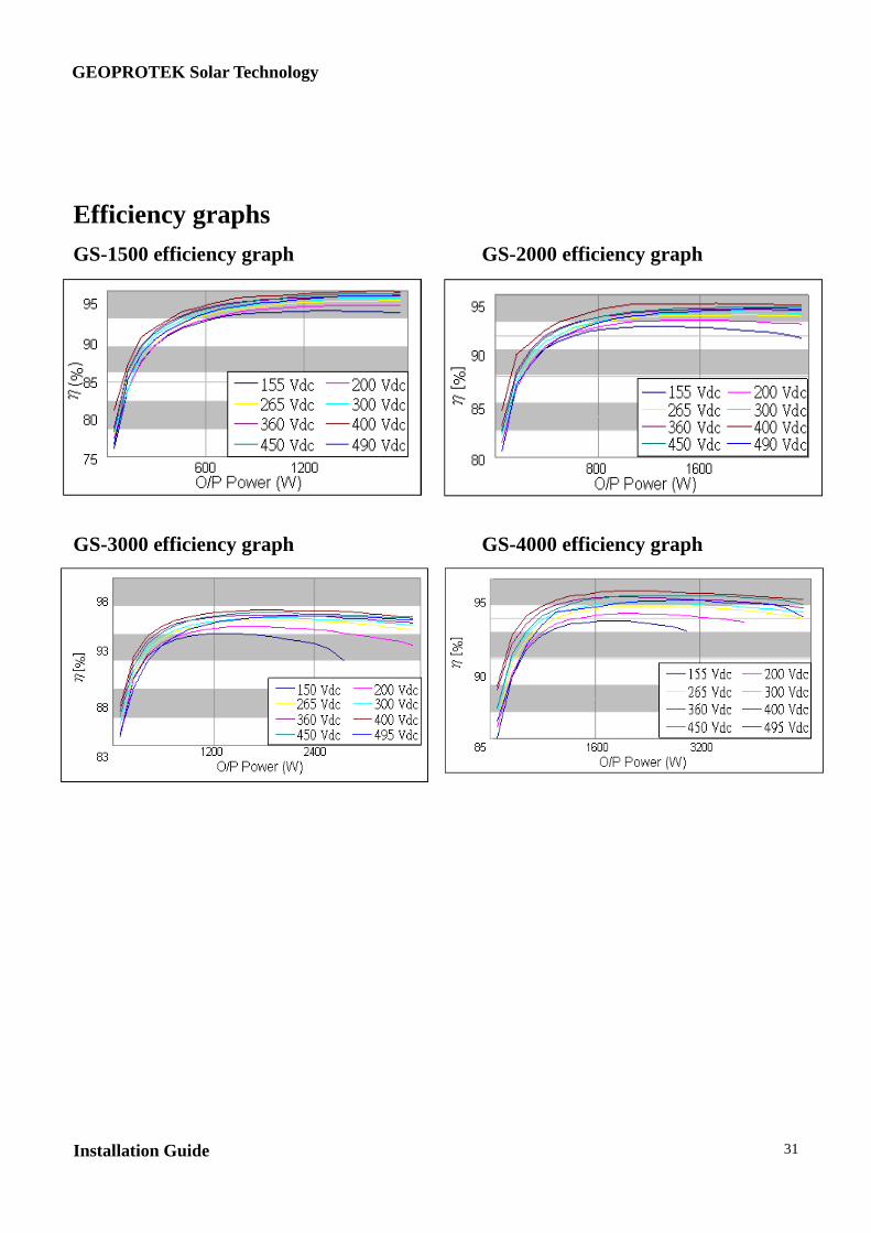
Efficiency graphs
GS-1500 efficiency graph GS-2000 efficiency graph GS-3000 efficiency graph GS-4000 efficiency graph
GEOPROTEK Solar Technology
Installation Guide 32
Installation Guide GS-1500, GS-2000, GS-3000, GS-4000
The information contained in this document is the property of GEOPROTEK Solar Technology. Publishing its content,
either partially or in full, requires the written permission of GEOPROTEK Solar Technology. Any internal company
copying of the document for the purposes of evaluating the product or its correct implementation is allowed and does not
require permission.
GEOPROTEK Solar Technology Product Warranty
• The inverter warranty time is 5 years. See also Powerbox Australia Warranty Terms & Conditions.
• If the inverter is fault, please contact our Australian agent – Powerbox Australia Pty Ltd or its assign agent.
Exclusion of liability
The general terms and conditions of delivery of GEOPROTEK Solar Technology shall apply. The content of these
documents is continually checked and amended, where necessary. However, discrepancies cannot be excluded. No
guarantee is made for the completeness of these documents.
Guarantee or liability claims for damages of any kind are excluded if they are caused by one or more of the following:
• Damages during transportation
• Improper or inappropriate use of the product
• Operating the product in an unintended environment
• Operating the product whilst ignoring relevant, statutory safety regulations in the deployment location
• Ignoring safety warnings and instructions contained in all documents relevant to the product
• Operating the product under incorrect safety or protection conditions
• Altering the product or supplied software without authority
• The product malfunctions due to operating attached or neighboring devices beyond statutory limit values
• In case of unforeseen calamity or force majeure
The use of supplied software produced by Geoprotek Tech Inc is subject to the following conditions:
• Geoprotek Tech Inc. rejects any liability for direct or indirect damages arising from the use of software developed by
Geoprotek Tech Inc. This also applies to the provision or non-provision of support activities.
• Supplied software not developed by Geoprotek Tech Inc is subject to the respective licensing and liability agreements
of the manufacturer.
Geoprotek Product Warranty
The current guarantee conditions come enclosed with your device. These are also available online at www.geoprotek.com
and can be downloaded or are available on paper from the usual sales channels if required.
Trademarks
All trademarks are recognized even if these are not marked separately. Missing designations do not mean that a product or
brand is not a registered trademark.
GEOPROTEK Solar Technology.
Tel. +886 2 2659 7969
Fax +886 2 2659 7668
www.geoprotek.com
E-Mail: [email protected]

GEOPROTEK Solar Technology
Installation Guide 33
Powerbox Australia Warranty Terms and Conditions
It is extremely important that all installation instructions contained within this manual are strictly adhered to. Failure to
do so will void your warranty.
If this unit is installed within 1km of the coast steps should be taken to prevent salt water or spray entering the unit.
Any corrosion related problems are not covered under the terms of this warranty. A fully marinised version of this unit
is not available.
Powerbox Australia warrants this inverter against defects in material or workmanship (as per manufacturer’s warranty),
for a period of five (5) years from the date of purchase, when in normal use and service. The warranty period will
provide a total of five (5) years if a completed warranty card is received within 60 days of purchase. No warranty will
be provided on units, which have not been paid for in full. Some models may have the option of purchasing an
extended warranty period. This warranty is in addition to your consumer rights under local trade practices act and the
manufacturer’s (Geoprotek Tech Inc) warranty.
This warranty does not extend to products which have been opened, altered or repaired by persons other than those
authorised by Powerbox Australia or to products which become defective due to acts of God, fire, sabotage, vandalism,
contaminated fluids, negligence or failure to operate, house and maintain the product in accordance with instructions
provided in this manual.
This warranty does not cover repairs made necessary due to the product coming in contact with dirt, abrasives,
moisture, erosion, corrosion, varnish or other similar, or failure due to poor quality of other system components.
Powerbox Australia will repair or replace the defective product in accordance with its best judgment. For service under
warranty, the buyer must contact Powerbox Australia to obtain a “Return Materials Advice” (RMA) document and
shipping instructions before returning the unit. Products returned without prior authorisation may be delayed. The
buyer will pay all charges incurred in returning the product to the factory, including any charges incurred for the
uninstallation or reinstallation of the inverter and / or its system components. Powerbox Australia will pay return
freight charges, if the product is found to be defective, within the terms of this warranty. Repair or replacement of any
unit does not extend the original warranty terms in any way.
Powerbox Australia reserves the right, with some models, to supply an accredited installer with replacement parts
(Aust. only). This may allow the unit to become operable much quicker. This choice is at Powerbox Australia’s
discretion. Powerbox Australia will in no way be held responsible for any losses incurred due to the malfunctioning or
failure of a product.
Suitably qualified personnel MUST carry out wiring. Failure to do so cannot justify a warranty claim.
Except for the foregoing expressed warranty, Powerbox Australia makes no other warranty, expressed or implied,
including but not limited to, the warranty of merchantability or fitness for a particular purpose.
If you have any questions about this warranty please do not hesitate to contact us.
NOTE: Packing for service and transportation - we recommend you keep the original packing in which your
Geoprotek inverter was supplied. This is the best way to protect your unit should shipping be required.
Powerbox Australia cannot be held responsible for units damaged in transit.
GEOPROTEK Solar Technology
Installation Guide 34