Embed Size (px)
Citation preview
George DavidAssociate Professor
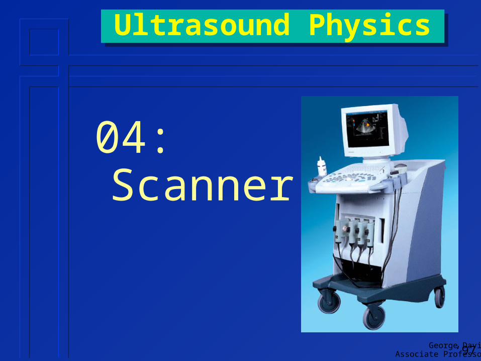
Ultrasound PhysicsUltrasound Physics
04:Scanner
‘97
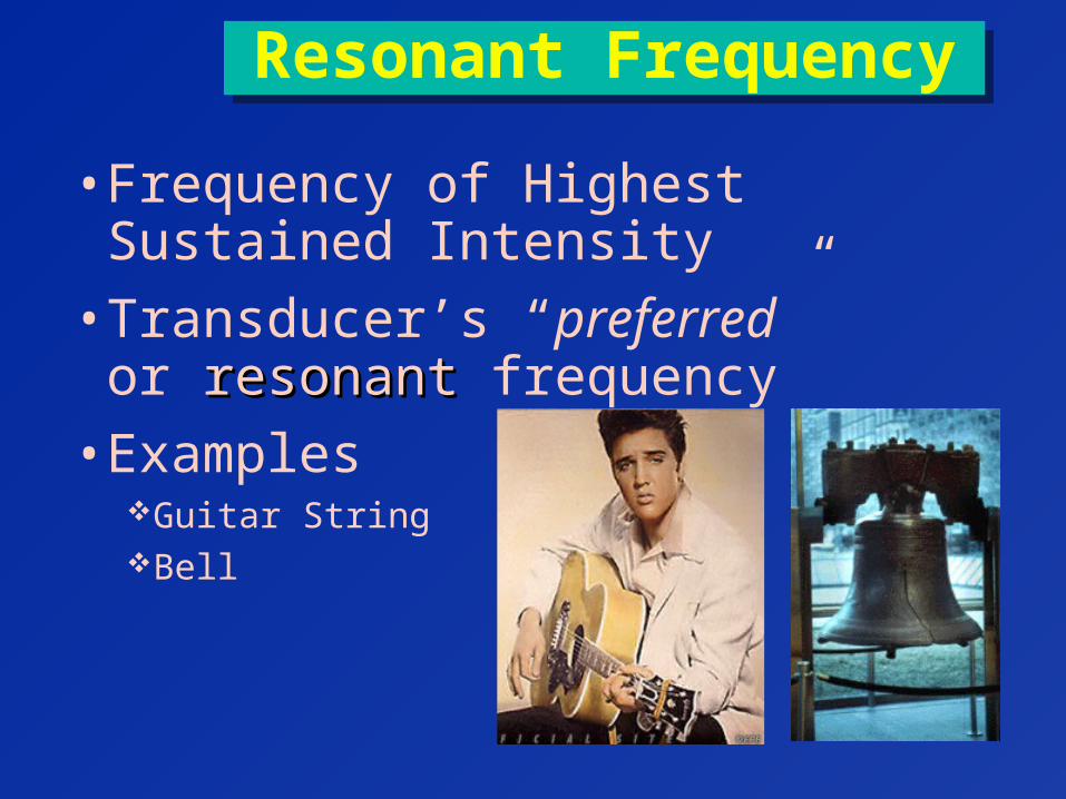
Resonant FrequencyResonant Frequency
• Frequency of Highest Sustained Intensity
• Transducer’s “preferred” or resonantresonant frequency
• ExamplesGuitar StringBell
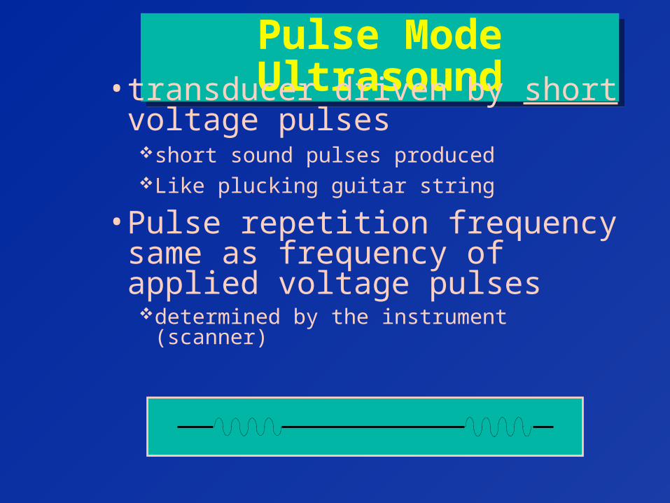
Pulse Mode UltrasoundPulse Mode Ultrasound• transducer driven by short
voltage pulsesshort sound pulses producedLike plucking guitar string
• Pulse repetition frequency same as frequency of applied voltage pulsesdetermined by the instrument (scanner)
Pulse Duration ReviewPulse Duration Review
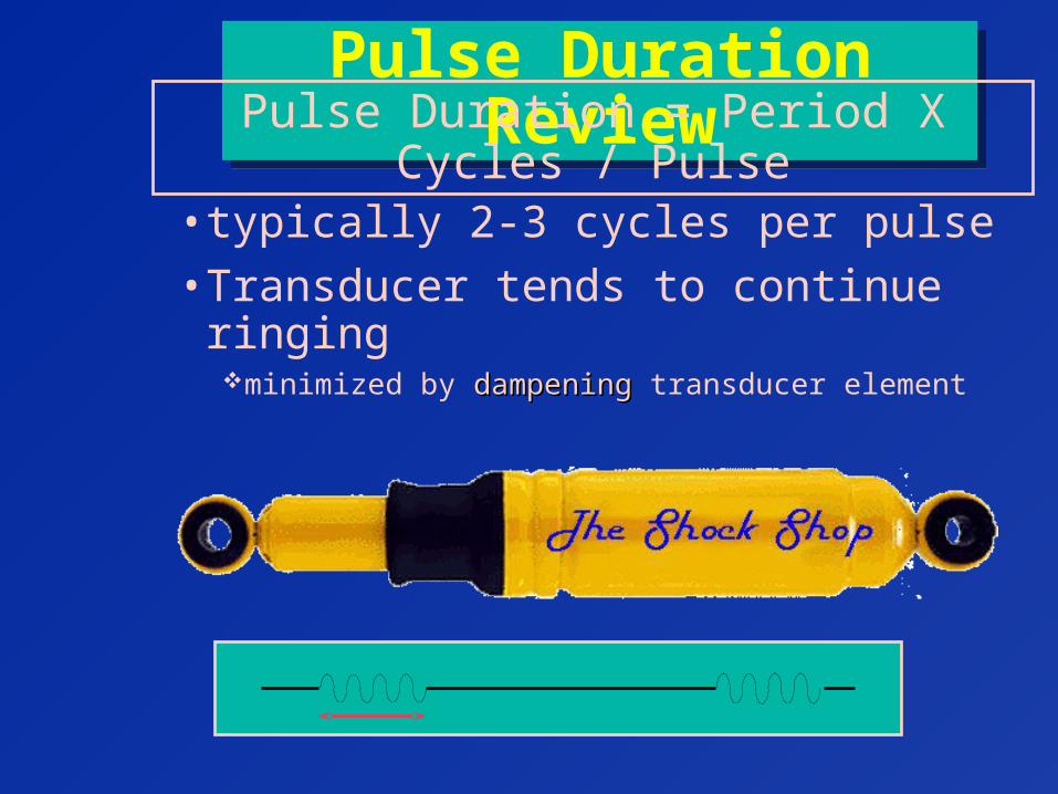
• typically 2-3 cycles per pulse
• Transducer tends to continue ringingminimized by dampeningdampening transducer element
Pulse Duration = Period X Cycles / Pulse
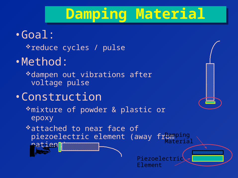
Damping MaterialDamping Material• Goal:
reduce cycles / pulse
• Method:dampen out vibrations after voltage pulse
• Constructionmixture of powder & plastic or epoxyattached to near face of piezoelectric
element (away from patient) DampingMaterial
PiezoelectricElement
Disadvantages of Damping
Disadvantages of Damping
• reduces beam intensity
• produces less pure frequency (tone)
George DavidAssociate Professor
BandwidthBandwidth
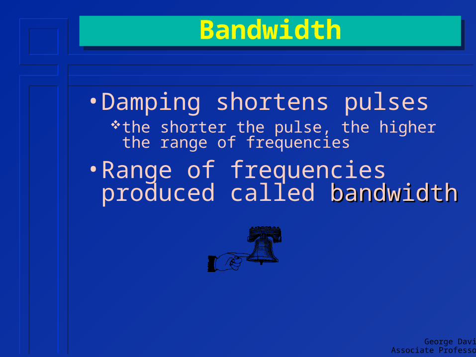
• Damping shortens pulsesthe shorter the pulse, the higher the range of
frequencies
• Range of frequencies produced called bandwidthbandwidth
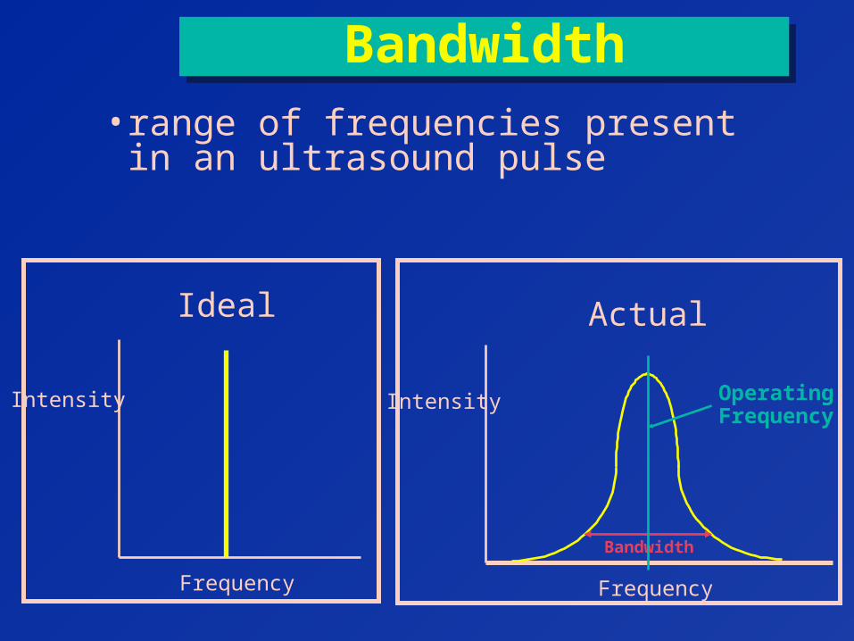
BandwidthBandwidth
• range of frequencies present in an ultrasound pulse
Frequency
Intensity
Ideal
Frequency
Intensity
Actual
Bandwidth
OperatingFrequency
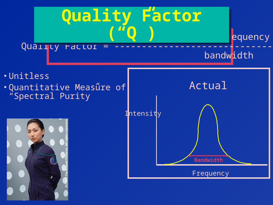
operating frequencyQuality Factor = -----------------------------
bandwidth
Quality Factor (“Q”)Quality Factor (“Q”)
• Unitless• Quantitative Measure of
“Spectral Purity”
Frequency
Intensity
Actual
Bandwidth
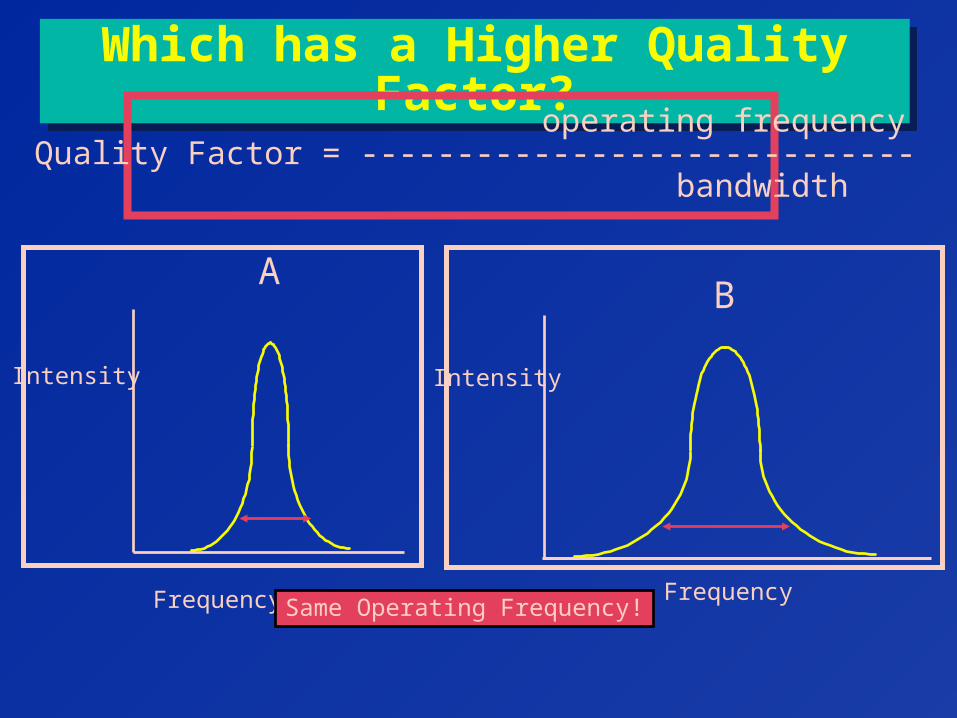
Which has a Higher Quality Factor?Which has a Higher Quality Factor?
Frequency
Intensity
A
Frequency
Intensity
B
operating frequencyQuality Factor = -----------------------------
bandwidth
Same Operating Frequency!
George DavidAssociate Professor
DampingDamping
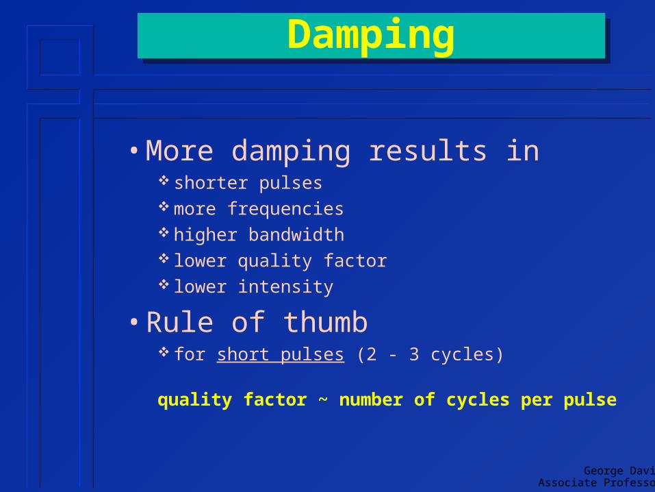
• More damping results in shorter pulses more frequencies higher bandwidth lower quality factor lower intensity
• Rule of thumb for short pulses (2 - 3 cycles)
quality factor ~ number of cycles per pulse
George DavidAssociate Professor
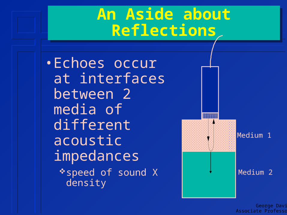
An Aside about ReflectionsAn Aside about Reflections
• Echoes occur at interfaces between 2 media of different acoustic impedancesspeed of sound X density
Medium 1
Medium 2
Intensity Reflection Coefficient (IRC)&
Intensity Transmission Coefficient (ITC)
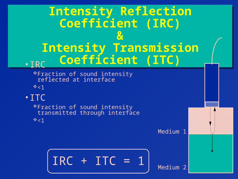
Intensity Reflection Coefficient (IRC)&
Intensity Transmission Coefficient (ITC)
• IRCFraction of sound intensity reflected at
interface<1
• ITCFraction of sound intensity transmitted through
interface<1
Medium 1
Medium 2IRC + ITC = 1
IRC EquationIRC Equation
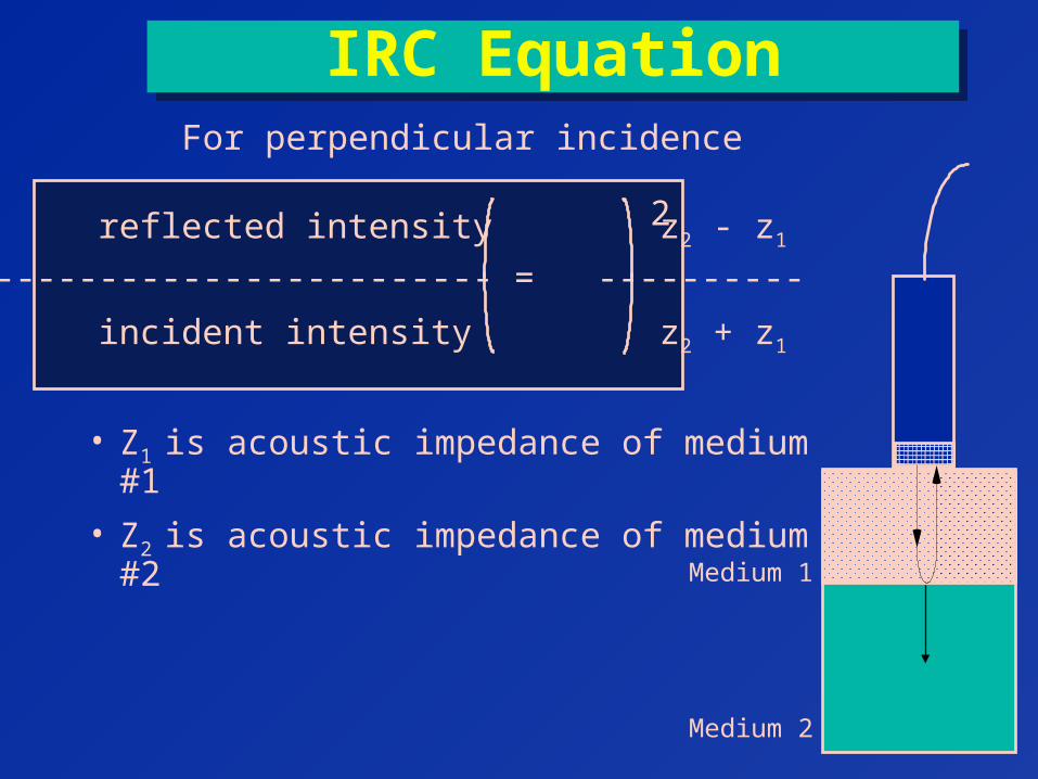
• Z1 is acoustic impedance of medium #1
• Z2 is acoustic impedance of medium #2
2 reflected intensity z2 - z1
IRC = ------------------------ = ----------
incident intensity z2 + z1
For perpendicular incidence
Medium 1
Medium 2
George DavidAssociate Professor
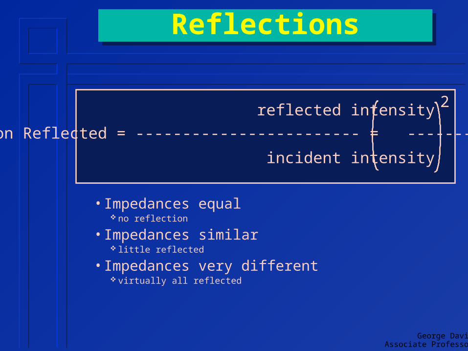
ReflectionsReflections
• Impedances equal no reflection
• Impedances similar little reflected
• Impedances very different virtually all reflected
2 reflected intensity z2 - z1
Fraction Reflected = ------------------------ = ----------
incident intensity z2 + z1
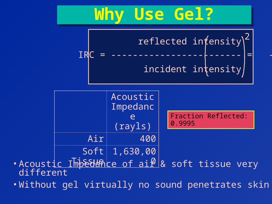
Why Use Gel?Why Use Gel?
• Acoustic Impedance of air & soft tissue very different• Without gel virtually no sound penetrates skin
2 reflected intensity z2 - z1
IRC = ------------------------ = ----------
incident intensity z2 + z1
Acoustic Impedance
(rayls)
Air 400Soft Tissue 1,630,000
Fraction Reflected: 0.9995
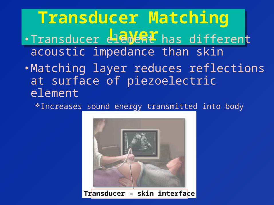
Transducer Matching LayerTransducer Matching Layer• Transducer element has different
acoustic impedance than skin
• Matching layer reduces reflections at surface of piezoelectric elementIncreases sound energy transmitted into body
Transducer – skin interface
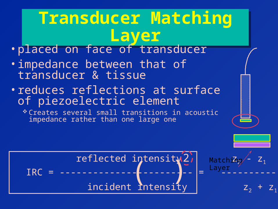
Transducer Matching LayerTransducer Matching Layer
• placed on face of transducer• impedance between that of transducer
& tissue• reduces reflections at surface of
piezoelectric element Creates several small transitions in acoustic impedance
rather than one large one
reflected intensity z2 - z1
IRC = ------------------------ = ----------
incident intensity z2 + z1
( )2 Matching
Layer
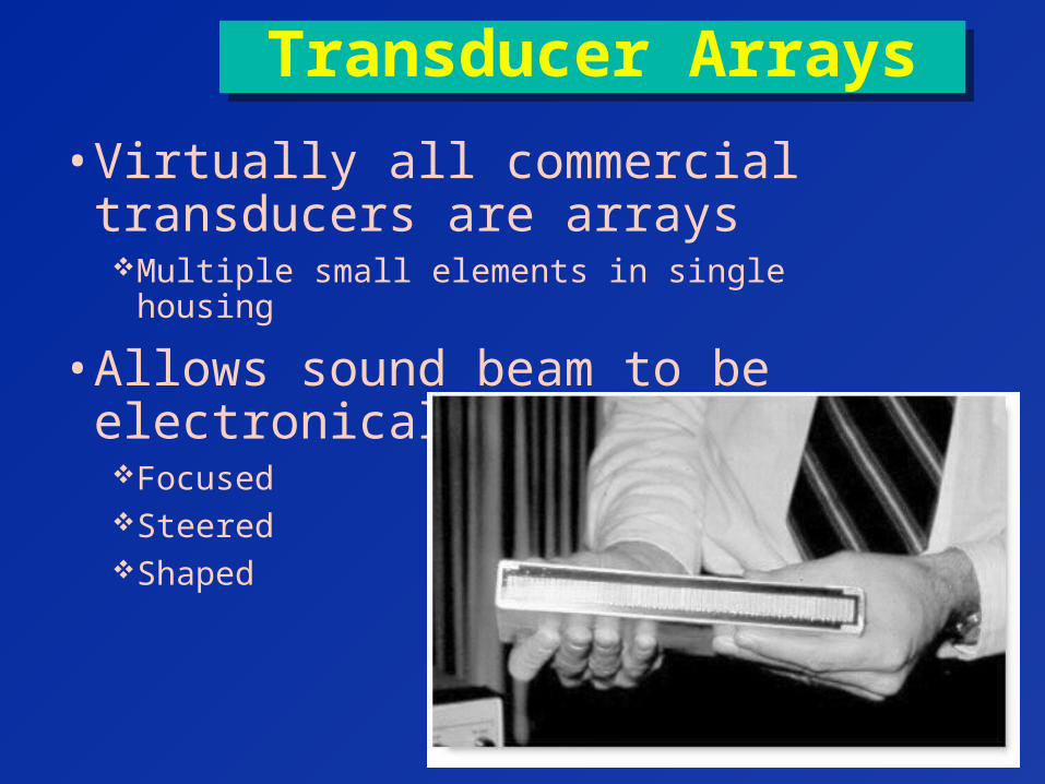
Transducer ArraysTransducer Arrays
• Virtually all commercial transducers are arraysMultiple small elements in single housing
• Allows sound beam to be electronicallyFocusedSteeredShaped
George DavidAssociate Professor
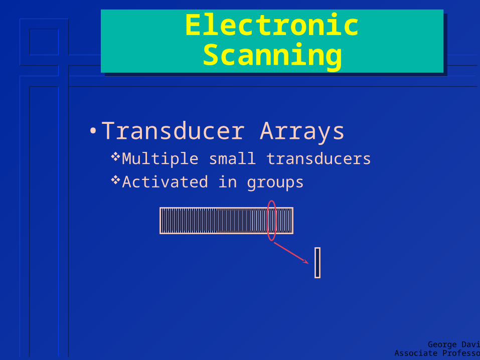
Electronic ScanningElectronic Scanning
• Transducer ArraysMultiple small transducersActivated in groups
George DavidAssociate Professor
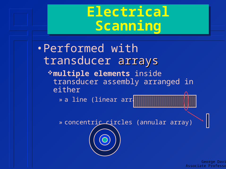
Electrical ScanningElectrical Scanning
• Performed with transducer arraysarraysmultiple elements inside transducer
assembly arranged in either» a line (linear array)
» concentric circles (annular array)
George DavidAssociate Professor
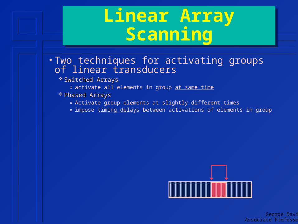
Linear Array ScanningLinear Array Scanning
• Two techniques for activating groups of linear transducers
Switched ArraysSwitched Arrays» activate all elements in group at same time
Phased ArraysPhased Arrays» Activate group elements at slightly different times» impose timing delays between activations of elements in group
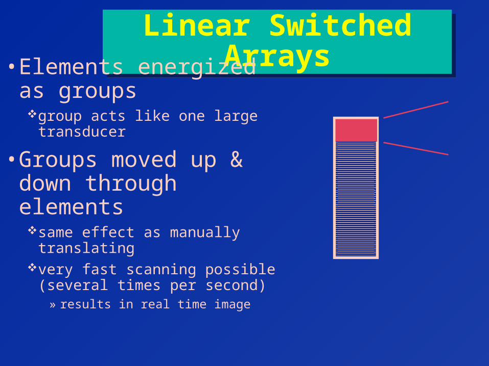
Linear Switched ArraysLinear Switched Arrays• Elements energized as
groupsgroup acts like one large
transducer
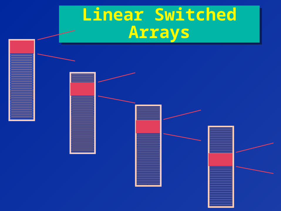
• Groups moved up & down through elementssame effect as manually
translatingvery fast scanning possible
(several times per second)» results in real time image
Linear Switched ArraysLinear Switched Arrays
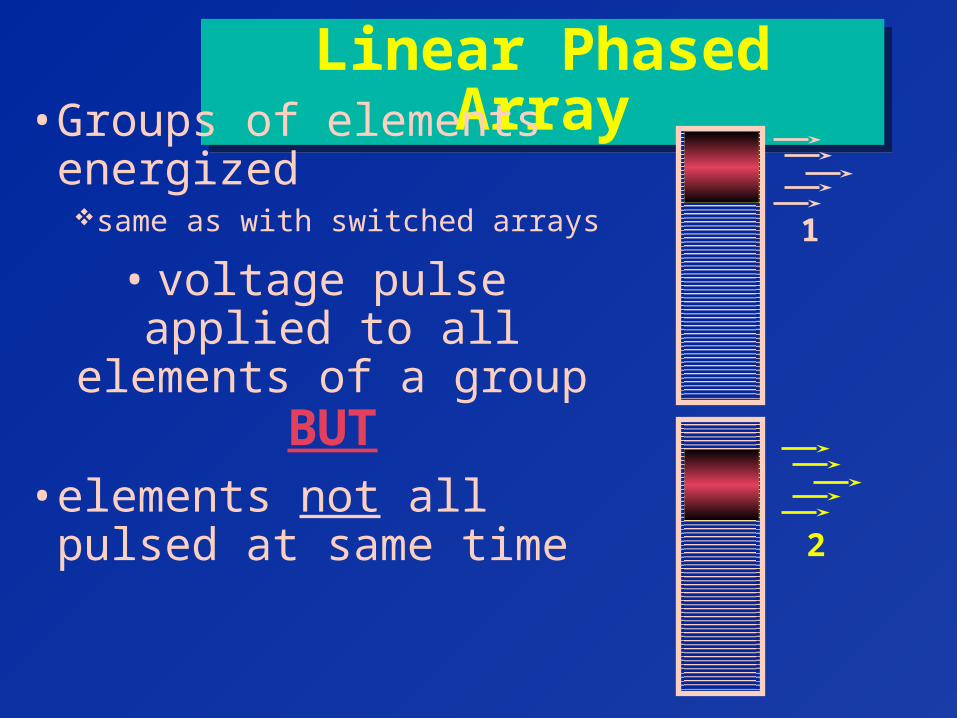
Linear Phased ArrayLinear Phased Array• Groups of elements
energizedsame as with switched arrays
• voltage pulse applied to all elements of a group
BUT• elements not all pulsed at
same time
1
2
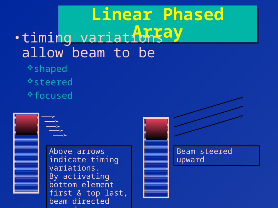
Linear Phased ArrayLinear Phased Array• timing variations allow
beam to be shapedsteeredfocused
Above arrows indicate timing variations.By activating bottom element first & top last, beam directed upward
Beam steered upward
Linear Phased ArrayLinear Phased Array
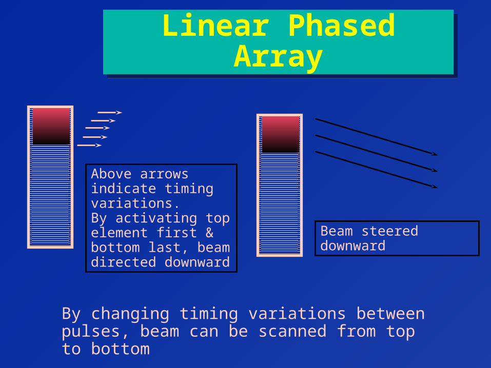
Above arrows indicate timing variations.By activating top element first & bottom last, beam directed downward
Beam steered downward
By changing timing variations between pulses, beam can be scanned from top to bottom
Linear Phased ArrayLinear Phased Array
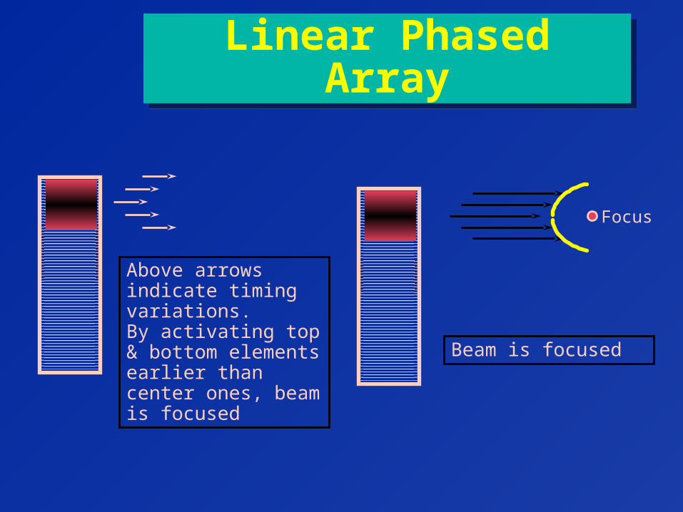
Above arrows indicate timing variations.By activating top & bottom elements earlier than center ones, beam is focused
Beam is focused
Focus
Linear Phased ArrayLinear Phased Array
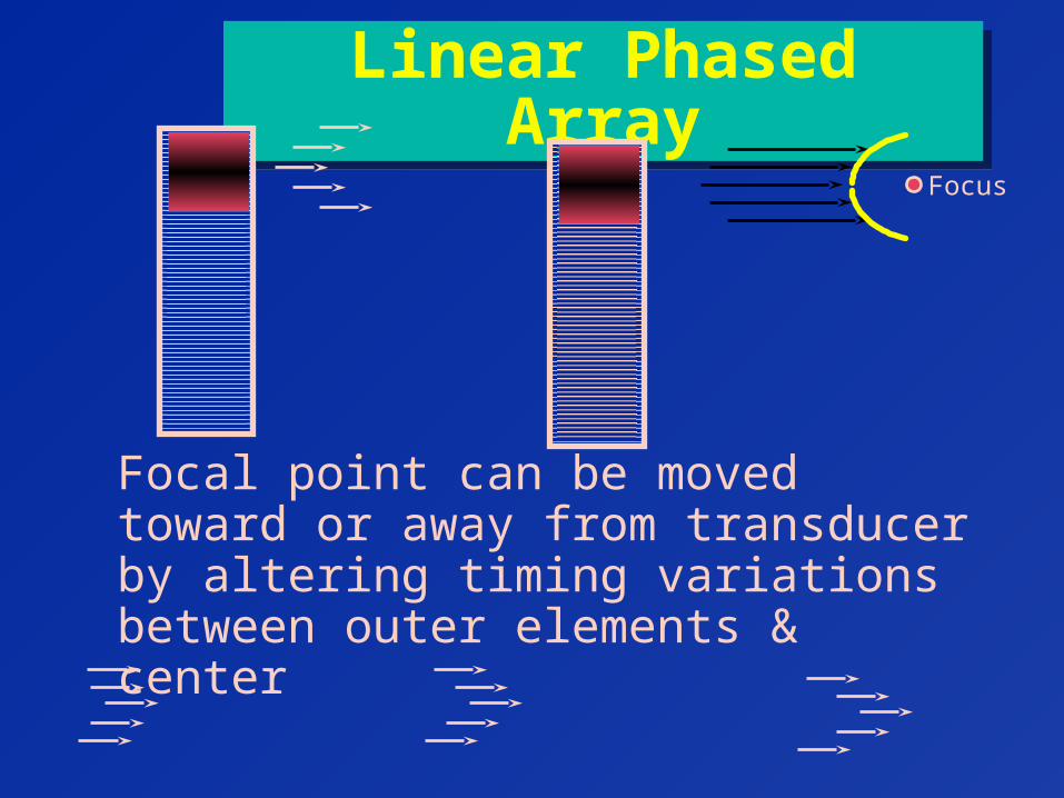
Focus
Focal point can be moved toward or away from transducer by altering timing variations between outer elements & center
Linear Phased ArrayLinear Phased Array
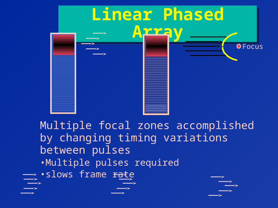
Focus
Multiple focal zones accomplished by changing timing variations between pulses•Multiple pulses required•slows frame rate
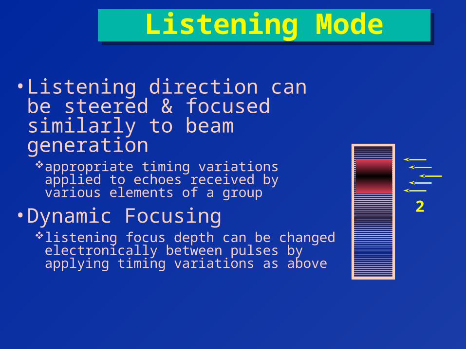
Listening ModeListening Mode
• Listening direction can be steered & focused similarly to beam generationappropriate timing variations applied to
echoes received by various elements of a group
• Dynamic Focusinglistening focus depth can be changed
electronically between pulses by applying timing variations as above
2