Embed Size (px)
Citation preview

Georgetown County Roadway Design &
Construction Manual
As Approved By Georgetown County Council November 18, 2014
Georgetown County Roadway Design and Construction Manual 11/11/2014
1
Georgetown County
Roadway Design and Construction Manual Introduction: Georgetown County Public Works Division is charged with improvements and maintenance of paved and unpaved roads of the unincorporated areas of Georgetown County. This includes the construction and maintenance of storm drainage systems (piping and ditches), right-of-way maintenance including the securing of R.O.W’s where needed, and coordination of Georgetown County’s pavement management program for secondary roads. It also includes the design and testing of road construction materials, the manufacture and installation of road signage (road names and traffic control), review of proposed development roads and associated drainage system, and the contracting and inspection of road improvement projects. Background of County Road Systems: Georgetown County road systems consist of contributed roads by developers and individual property owners, and roads by the County (in-house or contracted). There are approximately 955 roads in Georgetown County totaling 323 miles of roadway. 80 miles of these roads are paved and the other 243 miles consists of dirt roads and aggregate roads (stone, slag, recycled asphalt pavement (RAP) and other base materials). Right-of-ways vary on these roads. Some right-of-ways include only the maintained area of the roadway while others have mostly fifty foot right-of-ways. All developer contributed and County improvement roads require a minimum fifty foot road right-of-way. Existing roads vary in their cross section construction, right-of-way, drainage, materials of construction and design integrity. This is not uncommon as many of these roads were acquired by the County prior to standards for acceptance and through hardship waivers for access. Georgetown County upgrades roadways to a standard consistent with accepted design protocol as opportunities allow (including rights-of-ways, drainage, alignment and cross section improvement). The sections of this document that deal with road design and the related cross sectional figures will note roads that are non-standard roads for design, rights-of-way and drainage.

Georgetown County Roadway Design and Construction Manual 11/11/2014
2
Table of Contents: Chapter 1: General Provisions ............................................................................................ 7
1.1. Short Title ................................................................................................................ 7 1.2. Jurisdiction ............................................................................................................... 7 1.3. Purpose and Effect ................................................................................................... 7 1.4. Amendment and Revisions ...................................................................................... 7 1.5. Review and Approval .............................................................................................. 7 1.6. Interpretation ............................................................................................................ 7 1.7. Relationship to Other Standards .............................................................................. 7
Chapter 2: Construction Drawing Requirements ................................................................ 8
2.1. General Requirements .............................................................................................. 8 2.2. Cover Sheet .............................................................................................................. 8 2.3. Plan .......................................................................................................................... 8 2.4. Profile ....................................................................................................................... 9 2.5. Cross Sections .......................................................................................................... 9 2.6. Striping and Signing Plan ...................................................................................... 10 2.7. Details .................................................................................................................... 10 2.8. Standard Notes ....................................................................................................... 10
Chapter 3: Design and Technical Criteria ......................................................................... 12
3.1. General ................................................................................................................... 12 3.2. Street/Road Types .................................................................................................. 12 3.2.1. Public Street/Roads ......................................................................................... 12
3.2.2. Private Streets/Roads ...................................................................................... 12 3.3. Streets ..................................................................................................................... 12
3.3.1. Public and/or Private Road Rights-of-Way .................................................... 12 3.3.2. Relation to Adjoining Street System............................................................... 12 3.3.3. Retrofitting Existing Public or Private Road Rights-of-Way……...................13 3.3.4. Street Hierarchy .............................................................................................. 13 3.3.5. Trip Generation ............................................................................................... 13 3.3.6. Roadway Design Criteria ................................................................................ 13
3.4. Functional Classification ....................................................................................... 16 3.4.1. Freeway….……………………...……….……...…………….…………...….....…..16
3.4.2. Parkway….……...……………..……………………………………..…...….…..…16 3.4.3. Arterial. ........................................................................................................... 17 3.4.4. Collector .......................................................................................................... 17 3.4.5. Local ............................................................................................................... 17
3.5. Standard Templates ................................................................................................ 18 3.6. Horizontal Alignment ............................................................................................ 19
3.6.1. Superelevation................................................................................................. 19 3.6.2. Sight Distance ................................................................................................. 19
3.7. Vertical Alignment................................................................................................. 20 3.7.1. Grades: ............................................................................................................ 20 3.7.2. Intersection Grades ......................................................................................... 21 3.7.3. Changing Grades. ............................................................................................ 21 3.7.4. Vertical Curves. .............................................................................................. 21 3.7.5. Connection with Existing Streets/Roads ......................................................... 22

Georgetown County Roadway Design and Construction Manual 11/11/2014
3
3.8. Intersections and Driveways .................................................................................. 22 3.8.1. Intersection Spacing ........................................................................................ 22 3.8.2. Sight Distance. ................................................................................................ 23 3.8.3. Acceleration and Deceleration Lanes ............................................................. 23 3.8.4. Left-Turn Lanes .............................................................................................. 26 3.8.5. Curb Returns ................................................................................................... 28 3.8.6. Driveway Spacing ........................................................................................... 30 3.8.7. Channelizing Islands ....................................................................................... 31 3.8.8. Driveways, Private Roads, and Non-Maintained Roads in County Right-of-
Way Standards……………………………………………………………….32 3.9. Drainage ................................................................................................................. 33
3.9.1. Crosspans ........................................................................................................ 33 3.9.2. Inlets ................................................................................................................ 33 3.9.3. Cross Slope ..................................................................................................... 33 3.9.4. Temporary Erosion Control ............................................................................ 33 3.9.5. Cross Culverts ................................................................................................. 34
3.10. Traffic Control ..................................................................................................... 34 3.10.1. Construction Traffic Control......................................................................... 34 3.10.2. Traffic Signals ............................................................................................... 34
3.11. Miscellaneous ...................................................................................................... 34 3.11.1. Guardrail ....................................................................................................... 34 3.11.2. Noise Attenuation ......................................................................................... 34 3.11.3. Street Lighting .............................................................................................. 34
Chapter 4: Pavement Design and Technical Criteria ........................................................ 35
4.1. General ................................................................................................................... 35 4.2. Pavement Design Report Submittal ....................................................................... 35 4.3. Subgrade Investigation........................................................................................... 36
4.3.1 Field Investigation ........................................................................................... 36 4.3.2. Boring Profiles ................................................................................................ 36 4.3.3. Classification Testing...................................................................................... 36 4.3.4. Soil Grouping .................................................................................................. 36 4.3.5. Subgrade Support Testing ............................................................................... 36
4.4. Pavement Design Criteria ...................................................................................... 37 4.4.1. Equivalent (18 Kip) Daily Load Applications (EDLA) .................................. 37 4.4.2. Design Serviceability ...................................................................................... 38 4.4.3. Minimum Pavement Section ........................................................................... 38 4.4.4. Flexible Pavement Strength Coefficients........................................................ 39 4.4.5. Portland Cement Concrete Working Stress (ft) .............................................. 40
4.5. Pavement Design Procedure .................................................................................. 40 4.5.1. Flexible Pavements ......................................................................................... 40 4.5.2. Rigid Pavements ............................................................................................. 41
4.6. Material Specifications .......................................................................................... 42 4.6.1. Violations of Approval Conditions. ................................................................ 42 4.6.2. Use of Materials Not Listed in Section 4.6. .................................................... 42 4.6.3. Material Specifications ................................................................................... 43

Georgetown County Roadway Design and Construction Manual 11/11/2014
4
Chapter 5: Construction Specifications and Standards ..................................................... 49 5.1. Construction Specifications ................................................................................... 49
5.1.1. Permits ............................................................................................................ 49 5.1.2. Bonds .............................................................................................................. 49 5.1.3. General Specifications .................................................................................... 49 5.1.4. Road Closures ................................................................................................. 50 5.1.5. Utility Installations.......................................................................................... 50 5.1.6. Base Course .................................................................................................... 50 5.1.7. Concrete .......................................................................................................... 50 5.1.8. Storm Sewer Pipe ............................................................................................ 50 5.1.9. Culverts ........................................................................................................... 50 5.1.10. Traffic Control Devices ................................................................................ 51
5.2 Construction Standards .......................................................................................... .52 Chapter 6 – Georgetown County Policies ......................................................................... 53
6.1. Improving Private Roads ....................................................................................... 53 6.1.1. Policy .............................................................................................................. 53 6.1.2. Process ............................................................................................................ 53 6.1.3. Criteria ............................................................................................................ 53 6.1.4. Liability ........................................................................................................... 54 6.1.5. Funding ........................................................................................................... 54
6.2. Accepting Roads into County Road Maintenance System .................................... 56 6.2.1. Policy .............................................................................................................. 56 6.2.2. Process ............................................................................................................ 56 6.2.3. Criteria ............................................................................................................ 56 6.2.4. Liability ........................................................................................................... 56 6.2.5. Funding ........................................................................................................... 57
6.3. Speed Limits for County Roads ............................................................................. 57 6.3.1. Policy .............................................................................................................. 57 6.3.2. Process ............................................................................................................ 57 6.3.3. Criteria ............................................................................................................ 58 6.3.4. Appeals ........................................................................................................... 58
Definitions..................................................................................................................... 59 Appendix A- Standard Templates
Template Description Page Public Street / Road Templates
1 Principal Arterial Street 1 2 Minor Arterial Street 1 3 Collector Street (36’ FL to FL) with Attached Sidewalks 1 4 Collector Street (36’ FL to FL) with Detached Sidewalks 2 5 Local Street (28’ FL to FL) with Attached Sidewalks 2 6 Local Street (28’ FL to FL) with Detached Sidewalks 2 7 Local Street (26’ FL to FL) with Attached Sidewalks 3 8 Local Street (26’ FL to FL) with Detached Sidewalks 3 9 Principal Arterial Road 3 10 Minor Arterial Road 4 11 Minor Collector Road 4 12 Local Road 4
Georgetown County Roadway Design and Construction Manual 11/11/2014
5
13 Cul-de-Sac for Local Streets 5 14 Partial Cul-de-Sac for Local Streets 6 15 Offset Cul-de-Sac for Local Streets 7 16 Cul-de-Sac for Local Roads 8 Private Streets/Roads and Non-Maintained Streets/Roads in County R.O.W Templates* 17 Private Street/ Road (No parking) 9 18 Pull Out for Private Street/Road 9 19 Hammerhead Turnaround 10
* The “non-maintained streets/roads in County R.O.W” templates can only be used if the following provisions apply:
1. The County is not holding a guarantee as a result of a previous development process that would require the construction of a County public standard street/road in the R.O.W..
2. The County does not wish to have the street/road constructed to a County public standard. 3. The street/road is not identified on the Georgetown County Major Thoroughfare Plan.
Appendix B- Standard Details
Detail Title Page 1 Curb and Gutter 1 2 6” Vertical Curb, Gutter and Attached Sidewalk 2 3 6” Vertical Curb, Gutter and Detached Sidewalk 2 4 Curb and Ramp Details 3 5 Curb and Ramp Details 4 6 Curb and Ramp Details 5 7 Curb and Ramp Details 6 8 Typical Intersection Crosspan 7 9 Driveway Section for 6” Vertical Curb and Gutter 8 10 Optional Driveway Section for Combination Curb, Gutter and Sidewalk 9 11 Driveway/ Private Road Approaches for Roads 10 12 Typical Median Designs 11 13 Concrete Joint Details 12 14 Asphalt Street/ Road Patchback 13 15 Road and Street Name Signs 13

Georgetown County Roadway Design and Construction Manual 11/11/2014
6
Appendix C- Roadway Design Nomographs for Pavement
Figure Title Page C1 Design for Flexible Pavements Serviceability Index 2.0 1 C2 Design for Flexible Pavements Serviceability Index 2.5 2 C3 Design for Rigid Pavements Serviceability Index 2.0 3 C4 Design for Rigid Pavements Serviceability Index 2.5 4
Appendix D- Roadway Classifications & Design Guideline Tables
Table Title Page
D-1 Summary of Minimum Standards for Streets Based on Design Criteria 1
D-2 Summary of Maximum Grades for Vertical Roadway Alignment Design 2
D-3 Street Hierarchy Definitions 3 D-4 Trip Generation Rates by Major Land Use Categories 4 D-5 Alternate Dead-End Configurations 5
Appendix E Forms and Checklist
Form Title Page E-1 Private Road Petition 1 E-2 Right-of-Way Dedication Form 2 E-3 Drainage Easement Dedication Form 5 E-4 Speed Limit Adjustment Petition Form 8 E-5 Subdivision Inspection Checklist 9

Georgetown County Roadway Design and Construction Manual 11/11/2014
7
Chapter 1: General Provisions 1.1. Short Title These regulations together with all future amendments shall be known as the “Georgetown County Roadway Design and Construction Manual” (hereafter called MANUAL) as referenced in the Georgetown County Land Development Regulations (hereafter called LDR).
1.2. Jurisdiction The requirements of this MANUAL shall apply to all subdividers, developers or other landowners, their employees, agents or contractors designing and constructing public and private streets/roads which are subject to review and approval by the County, pursuant to any County regulation or requirement.
1.3. Purpose and Effect Presented in this MANUAL are the minimum design and technical criteria for the design and construction of streets/roads. All design and construction of streets/roads shall meet or exceed the criteria set forth herein.
1.4. Amendment and Revisions These policies and criteria may be amended as required by county policy as new technology is developed, and/or if experience gained in the use of this MANUAL indicates a need for revision. Amendments and revisions will be made by the Public Works Division.
1.5. Review and Approval The County will review all submittals for general compliance with this MANUAL. An approval by the County does not relieve the owner, engineer, or designer from responsibility of ensuring that the calculations, plans, specifications and construction are in compliance with the MANUAL and accepted engineering practices.
1.6. Interpretation In interpretation and application of the provisions of the MANUAL, the following shall govern:
1. In its interpretation and application, the provisions shall be regarded as the minimum requirements for the protection of public health, safety, comfort, morals, convenience, prosperity, and welfare of the residents of the County.
2. Whenever a provision of this MANUAL and any other provision of the LDR or any provision in any law, ordinance, resolution, rule, or regulation of any kind, contains any restriction covering any of the same subject matter, whichever restrictions are more restrictive or impose higher standards of requirements shall govern.
3. This MANUAL shall not abrogate or annul any permits or approved reports, construction plans, easements, or covenants issued before the effective date of the MANUAL.
4. Any interpretation of this manual will be made by the County Public Works Engineer.
1.7. Relationship to Other Standards If an ordinance or special district imposes more stringent criteria than that in this MANUAL, this difference is not considered a conflict. If the State or Federal Government imposes stricter criteria, standards, or requirements, these shall be incorporated into the County’s requirement after due process and public inspection/review needed to modify the County’s regulations and standards.

Georgetown County Roadway Design and Construction Manual 11/11/2014
8
Chapter 2: Construction Drawing Requirements
2.1. General Requirements The construction drawing submittal shall be a complete package, which includes all details and documentation necessary for the construction of the proposed improvements. The plans shall be prepared by, or under the direction of a professional engineer, registered in the State of South Carolina, and qualified in the field of civil engineering. Each drawing shall be 24” x 36” and shall contain a title block, sheet number, scale, north arrow and date. The construction drawings will be stamped by the responsible engineer and he/she will affix their signature across the stamped seal.
2.2. Cover Sheet A cover sheet should be provided with each submittal which contains the following:
1. A vicinity map at a minimum scale of 1” - 2000’ which shows the location and name of all arterial streets/roads within one mile of the proposed development and all streets/roads within the proposed development.
2. A legend. 3. General notes. 4. Index of sheets. 5. Seal and signature of the professional engineer responsible for plan preparation. 6. A permanent benchmark description and location based on USGS datum. At least one
permanent benchmark must be established within each subdivision or filing thereof, located on public property.
If a cover sheet is not provided, the above information shall be included on the first sheet of the submittal.
2.3. Plan The plan view shall include but not be limited to, the following:
1. The scale shall be one (1) inch to fifty (50) feet or less. 2. Locations and dimensions of existing and proposed property lines, easements, and
right-of-way. 3. Names of streets/roads. 4. Survey line ties to section or quarter corners. 5. Survey lines and centerline stationing. Stationing shall be equated to flow line
stationing at horizontal radius curves, cul-de-sacs, and other departures from normal roadway cross sections.
6. Centerline stations for all intersecting roadways and commercial driveways. 7. Existing and proposed street/road improvements (sidewalk, curb, gutter, pavement
limits, bridges, culverts, guardrails, handicap ramps, etc.). Existing improvements shall be depicted by a dashed line; proposed improvements shall be depicted by a solid line.
8. Curve layout will include radius, degree of curve, deflection angle, length of curve, point of curvature, and point of tangency.
9. Elevations and station shall be noted for all curb returns, points of curvature, points of tangency, high or low point of all vertical curves.
10. Rate of superelevation. 11. Typical template(s) for streets/roads.

Georgetown County Roadway Design and Construction Manual 11/11/2014
9
12. Match lines and consecutive sheet numbers. 13. Key map. 14. A minimum of one (1) permanent bench mark, based on United States Geological
Survey’s datum, fully described, within each subdivision or filing thereof. *15. Existing and proposed utilities and structures, including but not limited to:
• water (including valves) • fire hydrants • sanitary sewer (including manholes) • storm sewer (including inlets and access points) • communications: telephone, internet, etc. • gas • electric (differentiate aboveground vs. underground) • cable television • features associate with each respective utility including but not limited to: valves,
meters, pedestals, manholes, boxes, sewer cleanouts, etc. *16. Stations and critical elevations of all utility and drainage appurtenances. *17. Construction phasing. *18. Arterial intersection design at a scale of one (1) inch to twenty (20) feet. *19. Traffic signal design at a scale of one (1) inch to twenty (20) feet. *20. Noise attenuation measures/details. *21. Erosion control measures/details. *22. Landscaping.
* May be included on separate plan sheets.
2.4. Profile The profile shall include, but not be limited to the following:
1. The vertical scale shall be one (1) inch to five (5) feet. 2. Existing (dashed) and proposed (solid) grades. 3. Continuous stationing for the entire portion of the roadway shown in the plan view
with the centerline station for all intersecting roadways and commercial driveways clearly labeled.
4. All design elevations shall be centerline, top of curb, back of curb, or lip of gutter. 5. Vertical curve data including length of curve, P.V.C. (Point Vertical Curve, P.V.T.
(Point Vertical Tangent), P.V.I. (Point Vertical Intersection), Glossary of Terms, beginning and end grades. All vertical curves shall be symmetrical.
6. Curb return profiles at a horizontal scale of 1” = 10’ and vertical scale of 1” = 1’. 7. All existing curbs, gutters, sidewalks, and asphalt adjacent to the proposed design.
Basis for existing grades shall be as-built elevations at intervals not to exceed fifty (50) feet. Previously approved designs are not an acceptable means of establishing existing grades.
8. Separate flow line or top of curb profiles shall be provided for design of cul-de-sacs and any other departure from normal roadway cross slope.
*9. Existing and proposed utilities. * May be included on separate plan sheets.
2.5. Cross Sections On widening or matching projects, or as required by the Georgetown County Planning & Zoning Department, cross sections of the proposed new construction and existing improvements within the right-of-way shall be provided at a maximum of fifty foot intervals

Georgetown County Roadway Design and Construction Manual 11/11/2014
10
and at locations of cross culverts. The scale shall correspond to that used on the plan and profile.
2.6. Striping and Signing Plan The signing plan shall:
1. Show the general longitudinal location of each existing and proposed sign (by side of street/road and station).
2. Specify the sign legend and sign type from the FHWA-MUTCD (Federal Highway Administration – Manual an Uniform Traffic Control Devices) and the South Carolina Supplement, current editions.
3. Specify the sign size. 4. Include a typical detail of installation dimensions (height, distance from curb or edge
of pavement). 5. Include a detail of post and base dimensions and installation plan (showing any
wedges or sleeves, depth below surface, any materials used). 6. Specify the blank gauge and material of the sign(s). 7. Note the reflectorization provided.
The striping plan shall show:
1. Striping material (paint, thermoplastic, preformed tape, etc.). 2. Color designation and line width. 3. Lane width. 4. Stripe/skip. 5. Typical treatments for accel/decel lanes, turning lanes and crosswalks. 6. Applicable MUTCD references.
2.7. Details Georgetown County or South Carolina Department of Transportation standard details may be utilized with reference as applicable. Where these standards cannot be used, a separate detail sheet shall be provided and identified as supplemental details.
2.8. Standard Notes The following general notes shall appear on the cover sheet or the first sheet of the plans for all street/road construction plan packages.
1. An encroachment permit from the Georgetown County Public Services Department is required prior to commencing work within County right-of-way, or drainage easements.
2. Any work within State right-of-way will require a SCDOT Encroachment Permit. 3. The contractor shall notify the Georgetown County Public Works Division at least 24
hours prior to starting construction within the right-of-way. 4. The contractor shall provide all signs, barricades, flagmen, lights or other devices
necessary for safe traffic control in accordance with the current edition of the Manual on Uniform Traffic Control Devices as modified by the South Carolina Supplement to the MUTCD. A traffic control plan shall be submitted to and approved by the Georgetown County Public Works Division prior to the issuance of any construction permit for work within County right-of-way.
5. The contractor shall contact South Carolina 811 (sc1pups.org / 1-888-721-7877) at least 72 working day hours prior to construction, and request utility locates.

Georgetown County Roadway Design and Construction Manual 11/11/2014
11
6. Construction specification: Shall comply with the latest edition of the South Carolina Department of Transportation Standard Specifications for Road and Bridge Construction, special provisions and revisions thereto, and as amended by Chapter 5 of the Georgetown County Roadway Design and Construction Manual.
7. The subgrade material shall be scarified or removed to a depth required by Georgetown County according to information obtained from laboratory tests and/or as required in the Pavement Design Report. Additives or approved material may be required if the native material is unsatisfactory. The subgrade shall be compacted to a minimum density determined in accordance with AASHTO designation T180 or T99 and in accordance with the SCDOT Standard Specifications Section 208 (current editions).
8. Service trenches and utility main trenches shall be compacted throughout the depth of trench.
9. Class 6 aggregate base course for shoulders shall be placed and compacted to 95% Standard Proctor after placement of asphalt.
10. Existing asphalt pavement shall be straight saw cut or blade cut when adjoining with new asphalt pavement. SS-1 tack coat shall be applied to all surfaces.
11. Structural section shall be as approved by the Georgetown County Public Works Division, with pavement design in accordance with the Georgetown County Roadway Design and Construction Manual.
The following notes shall appear in addition to the above when concrete construction is utilized:
1. Concrete may be placed by machine methods provided that all finish lines are within 1/8” + tolerance of the lines shown on the plans. The flowline must be free draining. 2. One half (1/2) inch expansion joint material shall be installed when abutting any existing concrete or a fixed structure.

Georgetown County Roadway Design and Construction Manual 11/11/2014
12
Chapter 3: Design and Technical Criteria 3.1. General This section sets forth the minimum design standards for the construction of roadways, recreational spaces, utilities, and other improvements in new land development throughout Georgetown County. Use of higher standards is encouraged in all development designs. All new public and private streets shall be designed to identical standards unless otherwise stated.
3.2. Street/Road Types 3.2.1. Public Streets/Roads: Streets or roads that are owned and maintained by the City, County or State for public use. Does not include roads or streets maintained by private agencies such as property owner associations.
3.2.2. Private Streets/Roads: Streets or roads that are owned, maintained, or restricted for the use of a particular person, group of people or non-governmental entity.
3.3. Streets 3.3.1. Public and/or Private Road Rights-of-Way All streets shall be within a platted public right-of-way deeded fee simple or recorded easement to Georgetown County, the South Carolina Department of Transportation (SCDOT) or a platted private right-of-way deeded fee simple to a specific HOA, POA, or HPR or other entity. Prescriptive or other types of easements shall not be accepted for the purpose of conveying maintenance of streets or roads to Georgetown County, SCDOT, a homeowners’ association, or property management firms. The right-of-way shall be measured from lot line to lot line and shall contain the pavement, curbs, shoulders, sidewalks, graded areas, and utilities, when applicable. Right-of-way requirements are shown in the Appendix Table D-1. The minimum width of right-of-way, measured from lot line to lot line, for new highways, streets or extensions of existing roadways shall conform to the minimum values found in the Appendix Table D-1. The right-of-way shall reflect future development. Future development should be included in a separately submitted preliminary sketch plan.
3.3.2. Relation to Adjoining Street System The proposed street system shall extend existing streets when feasible or where the Planning Commission determines that extension of the proposed streets provides a public benefit. Such streets shall be extended at a width no less than the required minimum width as set forth in the Appendix Table D-1or the width of the existing street, whichever is greater. Sufficient access streets to adjoining properties shall be provided in subdivisions to permit harmonious development of the area. Where a subdivision abuts or contains an existing or proposed major street, the Planning Commission may require marginal access streets, reverse frontage with screen planting contained in a non-access reservation along the rear property line, or such other treatment

Georgetown County Roadway Design and Construction Manual 11/11/2014
13
as may be necessary for adequate protection of residential properties to afford separation of through and local traffic. 3.3.3. Retrofitting Existing Public or Private Road Rights-of-Way Subdivisions that adjoin existing streets shall dedicate additional rights-of-ways to meet the minimum street width requirements. The entire right-of-way shall be provided where any part of the subdivision is on both sides of the existing street. When the subdivision is located on only one side of an existing street, one-half of the required right-of-way, measured from the centerline of the existing roadway shall be provided. In no case shall the resulting right-of-way be less than fifty (50) feet.
3.3.4. Street Hierarchy Streets within Georgetown County shall be classified into the street hierarchy system shown in the Appendix Table D-3. Classification indicates the purpose of the street and the maximum average daily trips (ADT) that such street is to support. Improvement, right-of-way, and paving standards for such streets are shown in the Appendix Table D-1. 3.3.5. Trip Generation A land development may include a mixture of roadway types indicated in the Appendix Table D-3. The types of roadway required will depend on the type of development proposed (commercial, office, residential, etc.) and the average daily trips shown in the Appendix Table D-4. The regression formula for the specific land use, as published by the Institute of Transportation Engineers in the most recent version of the ITE Trip Generation Manual, may be substituted for the rates given. A licensed engineer shall certify the accuracy of the trip generation rate derived from the use of the regression method. 3.3.6. Roadway Design Criteria
1. Development Density, Paving Width, and Improvements: All proposed streets built for access to structure(s) shall be designed to be accessible to fire department apparatus by way of an approved right-of-way with asphalt, concrete, or other approved driving surface capable of supporting the imposed load of a minimum 80,600 pounds (34,050 kg). The required paving width and improvement standards for rights-of-way in land development shall be based on the development’s intensity as determined from the lot width at the building setback line of the lots within the land development. Appendix Table D-1 indicates the paving widths and improvement standards for the type of right-of-way at the various intensity levels. Roadway centerlines and right-of-way centerlines are to be coincident unless the road has received prior approval to be offset for additional lanes of traffic, turn lanes, etc.
2. Roadway Design Speed and Posted Speed: Design speed and posted speed limits for new public or private roadways shall be consistent with those shown the Appendix Table D-1. Variation from such speeds may be approved if roadway designs justify such variation and the variation has been approved by the Georgetown County Public Works Division.
3. Roadway Geometric Design Criteria:
New public or private roadways shall be designed to ensure that the roadway will function as intended in the Appendix Table D-1and will provide safe and efficient traffic movement to the public. Geometric features such as sight distances for stopping on
Georgetown County Roadway Design and Construction Manual 11/11/2014
14
horizontal and vertical curves, intersection sight distances, and horizontal and vertical curves shall be sized and designed in accordance with the standards published by the South Carolina Department of Transportation Highway Standards Manual or the AASHTO Manual for the roadway type that will be constructed.
4. Grades:
In the design of a roadway’s vertical alignment the maximum grade(s) to be used are shown in the Appendix Table D-2.
5. Dead-End Streets:
Minor terminal streets or courts designed to have one end permanently closed shall be no greater than eight hundred (800’) feet long unless necessitated by topography or land configuration and approved by the Planning Commission. They shall be provided at the closed end with a turnaround having an outside roadway diameter of at least eighty (80’) feet and a street right-of-way diameter of at least one hundred (100’) feet or the Planning Commission may approve an alternate design as shown in Appendix Table D-5. Streets less than 150’ in length will be handled on a case-by-case basis. Configurations shall be in consultation with the Fire Department. Where, in the opinion of the Planning Commission, it is desirable to provide for street access to adjoining property, proposed streets shall be extended to the boundary of such property. Such dead-end streets shall be provided with a temporary turnaround having a roadway diameter of at least eighty (80’) feet or other design approved by the Planning Commission.
6. Private Street and Reserve Strips and Gated Communities:
Private streets shall be allowed in both major and minor subdivisions. Private streets in major subdivisions shall be built to County or State standards and shall meet the design criteria found in Table 1 of Appendix A. Gated communities will only be allowed with County Council approval after receiving a recommendation from the Planning Commission. Related to this section of the Zoning Ordinance, communities are deemed to be residential subdivisions that contain or will contain E911 addresses and are served by a road that has not been gated and has generally been open for public use. Private roads associated with timber companies, farming and hunting clubs are exempt from acquiring Planning Commission and County Council approval. (Amended Ord. 2010-38) There shall be no reserve strips controlling access to streets, except where the control of such strips is definitely placed with the community under conditions approved by the Planning Commission.
7. Medians and Traffic Control Islands:
Natural or planted islands may be used in the center of cul-de-sacs on streets. Landscaping of such islands shall not interfere with the sight distance requirements. Natural or planted (with grass/shrubs) medians separating opposing traffic lanes shall be required as indicated in Table D-1. The minimum width of pavement on either side of the median is to be in accordance with the minimum lane widths contained in the Appendix Table D-1. The number of median openings required to serve abutting property shall be in accordance with SCDOT guidelines or standards.

Georgetown County Roadway Design and Construction Manual 11/11/2014
15
Maintenance of landscaped medians and traffic control islands within new public and private road rights-of-ways shall be the responsibility of the developer or deeded to a property owners’ association or other entity. Georgetown County is not responsible for upkeep and maintenance of landscaped medians.
8. Intersections:
Street intersections shall be as nearly at right angles as is possible. Whenever a proposed street intersects an existing or proposed street of higher order in the street hierarchy, the street of lower order shall be made a stop or yield street. No planted, constructed and/or erected obstruction to vision between 3.75 feet and ten (10’) feet above the finished street grade, measured at the edge of pavement, shall be located within the sight triangle.
9. Intersection Spacing:
To prevent dangerous street jogs, minimum intersection spacing shall be required.
For roadway intersections, see Section 3.8.1 Intersection Spacing and Table 3-8 Intersection Spacing. For driveway locations and spacing, see Section 3.8.6 Driveway Spacing, Figure 3-10 Driveway Spacing Measurement and Table 3-16 Driveway Spacing Design Information.
10. Tangents:
The tangent section between reverse curves, in horizontal roadway alignment, at a minimum shall be one hundred (100’) feet in length and shall be a function of the degree of the reverse curves, superelevation rate and the design speed of the roadway.
11. Drainage:
All streets and roads must be designed to provide for the discharge of surface water from the right-of-way by grading and drainage.
12. Street Names:
All design and installation of signs shall be in accordance with the latest editions of the Federal Highway Administration – Manual on Uniform Traffic Control Devices (FHWA-MUTCD), and the SCDOT Supplement to the MUTCD. At least two street name signs, at opposing intersections, shall be placed at each four-way street intersection, and one at each “T” intersection. Signs shall be installed free of visual obstruction. Private roads shall be required to provide signage in accordance with the requirements of this subsection. In addition, a sign shall be posted at the entrance of such development that states: “Private Road Not Maintained by Georgetown County.” It is the responsibility of the Planning Commission to approve and certify all street names within the territory of jurisdiction of the County.
The GIS division will determine the street designation based of the following criteria: NOTE: Where more than one apply, the applicant will be given the option.
a. Avenue – Roadways running east-west and longer in length then one thousand (1000’) feet.
b. Boulevard – A street with a median or landscaped center island and

Georgetown County Roadway Design and Construction Manual 11/11/2014
16
generally designated by a name. c. Circle – Short streets that return to themselves. d. Court – Dead end right-of-ways less than one thousand (1000’) in
length and run east-west. e. Drive – Diagonal, curvilinear or other types of roads greater than
one thousand (1000’) feet in length. f. Highway – US Routes, state or federal highways. g. Interstate – Roads of the highest order, characterized by limited
access and with through-traffic preference, wide rights-of-ways, prohibited adjacent to development.
h. Parkway – A special scenic route or park drive, generally designated by a name.
i. Path – A minor local street running in a diagonal direction, usually between a north-south avenue and an east-west street.
j. Pike – State primary-numbered roads. k. Place – Dead end rights-of-ways under one thousand (1000’) feet
running north-south. l. Road – Diagonal roadways longer than one thousand (1000’) feet
and generally designated by a name. m. Street – Roadways running north-south and longer in length than one
thousand (1000’) feet. n. Trail – A diagonal or curvilinear street. o. Way – A dead end, diagonal street under one thousand (1000’) feet in length.
13. The Engineer shall prepare all designs in accordance with current Americans with Disabilities Act (ADA) requirements, standards and guidelines, and shall ensure that applicable provisions and details are included in the plans and specifications.
3.4. Functional Classification In addition to the street and road classification descriptions provided below, refer to the AASHTO “Green Book” – A Policy on Geometric Design of Highways and Streets, for additional information pertaining to functional classifications.
3.4.1. Freeway: A freeway serves major regional traffic movements and carries the highest traffic volume of all classifications. A freeway is planned to have four to six through lanes and may have frontage roads. The movement of traffic takes precedence over access. Access is fully controlled and is allowed only to other freeways or arterials by grade separated interchanges. Opposing movements on a freeway are separated by a raised or depressed median. Pedestrians and bicycle traffic are physically separated from the travel lanes. A freeway may be developed as a parkway with at-grade intersections as a first phase. Design Speed: Special Design Required 3.4.2. Parkway: A parkway serves major regional traffic movements and carries high traffic volumes. A parkway is planned to have four to six through lanes. The movement of traffic takes precedence over access. Access is fully controlled and allowed only to freeways and arterials. Grade separation at major intersections is preferred over traffic signals.

Georgetown County Roadway Design and Construction Manual 11/11/2014
17
Opposing movements on a parkway are separated by a raised or depressed median. Pedestrians and bicycle traffic are physically separated from the travel lanes. Design Speed: 50 to 55 MPH 3.4.3. Arterial:
3.4.3.1. Principal Arterial: A principal arterial serves major regional traffic movements and carries high traffic volumes. A principal arterial is planned to have four to six through lanes. The movement of traffic takes precedence over access. Access only to arterials and higher class facilities is preferred, but some limited access to major developments may be allowed. Opposing movements are usually separated by a raised, depressed, or painted median. Pedestrians and bicycle traffic may be carried on detached walks and trails. Design Speed: 45 to 55 MPH
3.4.3.2. Minor Arterial: A minor arterial serves intra-community traffic and carries moderate traffic volumes. Minor arterials are planned to have four through lanes (and sometimes a continuous 2-way left turn lane). Neither the movement of traffic nor access takes precedence. Reasonable access is allowed with the exception of private residential driveways. Opposing movements are generally separated by a raised, depressed, or painted median. Pedestrians and bicycle traffic are usually carried on a detached walk or an adjacent trail. Design Speed: 40 to 50 MPH
3.4.4. Collector: A collector serves neighborhood traffic movements over short distances, generally accessing arterials. A collector has two lanes. Access takes precedence over the movement of traffic. Reasonable access is allowed with the exception of private residential driveways. Opposing movements are not physically separated. Pedestrian traffic is handled on attached or detached sidewalks in the plains. No special accommodation is made for bicycle traffic. Design Speed: 35 to 40 MPH 3.4.5. Local: A local street or road serves neighborhood traffic over very short distances to higher class roadways. A local street or road has two travel lanes. Access to adjacent land is its primary purpose. All types of access are allowed. Opposing movements are not physically separated. Pedestrian traffic is handled on attached or detached sidewalks. No special accommodation is made for bicycle traffic.

Georgetown County Roadway Design and Construction Manual 11/11/2014
18
3.5. Standard Templates The following templates reflect the minimum section for each street/road classification and for cul-de-sacs. Roads are allowed subject to approval by Planning and Zoning. Any additional requirements including, but not limited to, acceleration/deceleration lanes and turn lanes are not shown.
Table 3-3
Standard Templates (See Templates Appendix A)
Template Number Description
Public Street/Road Templates 1 Principal Arterial Street 2 Minor Arterial Street 3 Collector Street (36' FL to FL) with Attached Sidewalks 4 Collector Street (36' FL to FL) with Detached Sidewalks 5 Local Street (28' FL to FL) with Attached Sidewalks 6 Local Street (28' FL to FL) with Detached Sidewalks 7 Local Street (26' FL to FL) with Attached Sidewalks 8 Local Street (26' FL to FL) with Detached Sidewalks 9 Principal Arterial Road 10 Minor Arterial Road 11 Minor Collector Road 12 Local Road 13 Cul-de-Sac for Local Streets 14 Partial Cul-de-Sac for Local Streets 15 Offset Cul-de-Sac for Local Streets 16 Cul-de-Sac for Local Roads
Private Streets/Roads and Non-Maintained Streets/Roads in County R.O.W.
Templates*
17 Private Street/Road (No Parking) 18 Pull Out for Private Street/Road 19 Hammerhead Turnaround
* The “non-maintained streets/roads in County R.O.W.” templates can only be used if the following provisions apply:
1. The County is not holding a guarantee as a result of a previous development process that would require the construction of a County public standard street/road in the R.O.W. 2. The County does not wish to have the street/road constructed to a County public standard. 3. The street/road is not identified on the Georgetown County Major Thoroughfare Plan.

Georgetown County Roadway Design and Construction Manual 11/11/2014
19
3.6. Horizontal Alignment 3.6.1. Horizontal Curves: Minimum curve radii for a normal crown section based on design speed and applicable for urban streets, are summarized in the table below.
Table 3-4
Minimum Curve Radius for Design Speed
Design Speed (mph) Minimum Curve Radius (feet) 30 300 35 465 40 680
3.6.1. Superelevation: Superelevation is required for curves on all principal and minor arterial streets/roads and selected collector streets/roads. Minimum horizontal curve radius, rate of superelevation, and lengths of tangent runout and superelevation runoff shall be in accordance with the recommendations of the current edition of AASHTO. Superelevation shall not be used on local streets, but may be used on local roads. 3.6.2. Sight Distance: Horizontal alignment must provide at least the minimum stopping sight distance based on AASHTO for the design speed at all points. This includes visibility at intersections, as well as around curves and roadside encroachments. Where an object off the traveled surface restricts sight distance, the minimum radius of curvature is determined by the stopping sight distance. A likely obstruction may be a bridge abutment, retaining wall, cut slope, landscaping, or side or corner of a building. In considering sight distance, it shall be as-sumed a 6’-0” fence (as measured from finished grade) exists along all property lines except in the sight distance triangles required at all intersections. Minimum stopping sight distance (measured from the centerline of the inside lane) shall be as illustrated in FIG 3-1 and Table 3-5.

Georgetown County Roadway Design and Construction Manual 11/11/2014
20
Figure 3-1 Measuring Minimum Sight Distance
Table 3-5 Minimum Stopping Distance
Design Speed (mph) Stopping Sight Distance (D) (feet) 30 200 35 250 40 325 45 400 50 475
3.7. Vertical Alignment 3.7.1. Grades: The minimum grade for all streets and roads is 0.5%. Public Works Division will consider flatter grades only if the designer can clearly demonstrate that significant site constraints exist which realistically prelude achieving the minimum grade. A minimum flow line grade of 1.0% shall be maintained around all full and partial cul-de-sac bulbs. The maximum grade for all public streets is 6.0% and for public roads is 8.0%. Summary of Maximum Grades for Vertical Roadway Alignment is given in Appendix Table D-2. The alignment is a function of Street Hierarchy and Design Speed.
3.7.2. Intersection Grades: The maximum grade at intersections shall be in accordance with Figure 3-2 and Table 3-6.
6’ Fence Along Property
Note: D= Measurement from center of lane to center of lane
Increase curve radius, remove obstructions or regrade as necessary to provide required sight distance
Property Line
Edge of asphalt

Georgetown County Roadway Design and Construction Manual 11/11/2014
21
Grades and lengths apply to the street/road controlled by a stop sign. At signalized and uncontrolled intersections, grades and lengths apply to all legs of the intersection.
FIG 3-2
Table 3-6 Through Street / Road
Intersection Street/Road Local Collector Arterial Local 50’ @ 4% 100’ @ 4% 100’ @ 4% Collector - 100’ @ 3% 200’ @ 2% Arterial - - 200’ @ 2%
3.7.3. Changing Grades: Continuous grade changes shall not be permitted. The use of grade breaks in lieu of vertical curves is discouraged; however, if a grade break is necessary and the algebraic difference in grade (A) does not exceed four-tenths (0.40) of a percent along the street/road, the grade break will be permitted. The maximum grade break allowed at the point of tangency at a curb return for local and collector streets shall be two (2) percent and a maximum of one (1) percent for arterial streets. 3.7.4. Vertical Curves: All vertical curves shall be symmetrical. A vertical curve shall be used when the algebraic difference in grade (A) equals or is greater than four-tenths (0.40) of a percent. The minimum grade within a sag (sump) vertical curve is five-tenths (0.50) of a percent. All vertical curves shall be labeled, in the profile with curve length (L) and K value (= L/A). The minimum K values for crest and sag vertical curves shall be in accordance with Table 3-7.

Georgetown County Roadway Design and Construction Manual 11/11/2014
22
Table 3-7 Minimum K Value
Design Speed (mph) Crest Sag 30 30 40 35 50 50 40 80 70 45 120 90 50 160 110
For design of local streets/roads, K values for 30 mph design speed shall be used.
3.7.5. Connection with Existing Streets/Roads:
3.7.5.1. Connection with existing roadways shall be smooth transitions conforming to normal vertical curve criteria (see Section 3.7.4. of these standards) if the algebraic difference in grade (A) between the existing and proposed grade exceeds four-tenths (0.40) of a percent. When a vertical curve is used to make this transition, it shall be fully accomplished prior to the connection with the existing improvement, and also comply with the grade requirements at intersection approaches.
3.7.5.2. Existing grade shall be shown for at least three hundred (300) feet with field verified as-builts showing stations and elevations at twenty-five (25) foot intervals. In the case of connection with an existing intersection, these as-builts are to be shown within a three hundred (300) foot radius of the intersection. This information will be included in the plan and profile that show the proposed roadway. 3.7.5.3. Previously approved designs for the existing improvement are not an acceptable means of establishing existing grades; however, they are to be referenced on the construction plan where they occur. 3.7.5.4. The basis of the as-built elevations shall be the same as the design elevations (both flowline or top of curb, etc.) when possible.
3.8. Intersections and Driveways 3.8.1. Intersection Spacing: Spacing of intersections (measured centerline to centerline) shall be in accordance with the following table:
Table 3-8 Intersection Spacing
Street/Road Classifications Minimum Separation (feet) Local/Local 300 Local/Collector 300 Local/Arterial 1,320 Collector/Collector 500 Collector/Arterial/Parkway 1,320 Arterial/Arterial/Parkway 5,280

Georgetown County Roadway Design and Construction Manual 11/11/2014
23
3.8.2. Sight Distance: Sight distance design shall be in accordance with the AASHTO “Green Book” – A Policy on Geometric Design of Highways and Streets, the SCDOT Access & Roadside Management Standards (ARMS) Manual, and the SCDOT Roadway Design Manual. When the criteria for sight distances cannot be met, the County may deny the access, prohibit certain turning movements, require speed change lanes, or require other measures as deemed appropriate on a case-by-case basis. 3.8.3. Acceleration and Deceleration Lanes:
3.8.3.1. Acceleration Lanes: Right turn acceleration lanes are required at arterial street/road intersections and at driveways on arterial streets/ roads when the DHV (Design Hourly Volume) values of the street/road single lane and the DHV of right turns intersect at a point on or above the curve for the posted speed on the following graph. Right turn acceleration lanes may also be required where necessary for public safety and traffic operations based upon site specific conditions, as determined by Planning and Code Enforcement.

Georgetown County Roadway Design and Construction Manual 11/11/2014
24
FIG 3-4
Right Turn Acceleration Lanes
3.8.3.2. Deceleration Lanes: Right turn deceleration lanes are required at arterial street/road intersections and at driveways on arterial streets/ roads when the DHV values of the street/road single lane and the DHV of right turns intersect at a point on or above the curve for the posted speed on the following graph. When the right turn DHV is less than five, right turn acceleration lanes may be required due to high through traffic volumes or other site specific safety considerations, as determined by Planning and Code Enforcement.
FIG 3-5 Right Turn Deceleration Lanes
3.8.3.3. If the proposed street/road intersection or driveway is within two different speed zones, the criteria for the higher speed zone apply. 3.8.3.4. Where there are three or more through lanes in the direction of travel, right turn

Georgetown County Roadway Design and Construction Manual 11/11/2014
25
acceleration and deceleration lanes will be required only when determined necessary by Planning and Code Enforcement due to high traffic volume or other site specific safety considerations. 3.8.3.5. Taper and lane lengths shall be in accordance with Figure 3-6 and Table 3-11.
Table 3-11 Deceleration Lanes Design Information
Design Speed
(M.P.H.)
Taper Length (For 12’
Lane Width)
Taper Ratios
(For > 12’ Lane Width)
Lane Length
Total Length 1
(Taper Length + Lane Length)
30 100’ 8:3 150’ 250’ 40 140’ 12:1 230’ 370’ 45 160’ 13:1 280’ 440’ 50 180’ 15:1 320’ 500’
1At signalized intersections, where storage is needed for right-turning vehicles, additional length shall be provided to accommodate the average number of vehicles anticipated.
Table 3-12 Acceleration Lanes Design Information
Fig 3-6 Acceleration Lane and Deceleration Lane Measurement
3.8.3.6. A continuous accel/decel lane is required if the acceleration lane for one access and the deceleration lane for another access overlap or are in close proximity to each other. 3.8.3.7. The minimum pavement width for acceleration and deceleration lanes shall be twelve (12) feet, excluding gutter pan or shoulder.
Design Speed
(M.P.H.)
Taper Length (For 12’
Lane Width)
Taper Ratios (For 12’
Lane Width)
Lane Length
Total Length 2
(Taper Length + Lane Length)
30 120’ 10:1 190’ 310’ 40 180’ 15:1 380’ 560’ 45 180’ 15:1 550’ 730’ 50 240’ 20:1 760’ 1000’
2Acceleration lanes at low-volume stop sign controlled cross streets/roads may consist of 300 lineal feet of taper only.

Georgetown County Roadway Design and Construction Manual 11/11/2014
26
3.8.3.8. Grade correction factors are required where street/road grades are steeper than three (3) percent.
3.8.4. Left-Turn Lanes: Left-turn lanes are required at all arterial street/road intersections and at driveways on arterial streets/roads. Design of left-turn lanes shall be in accordance with FIG 3-7 and Table 3-13.
FIG 3-7 Left Turn Lane Measurements
Table 3-13 Left-Turn Lane Design Information
Design Speed
(M.P.H.)
Taper Length (For 12’
Lane Width)
Taper Ratios
(For > 12’ Lane Width)
Decel Length
2 Storage Length At: Signalized & Unsignalized Intersections
Total Length
30 100’ 8:1 150’ Determined From
Nomographs Figs 3-8 & 3-9
1 250’ 40 140’ 12:1 230’ 1 370’ 45 160’ 13:1 280’ 1 440’ 50 180’ 15:1 320’ 1 500’
1 Plus storage length 2 Minimum storage length is 40 feet
3.8.4.1. Storage lengths for signalized and unsignalized intersections shall be in accordance with the following FIG 3-8 and FIG 3-9.

Georgetown County Roadway Design and Construction Manual 11/11/2014
27
FIG 3-8 Design of Left Turn Storage Length Volume-Based Chart for At-Grade Unsignalized
Intersections on Four Lane Roadways
FIG 3-9 Design of Left Turn Storage Length Volume-Based Chart for
At-Grade Signalized Intersections

Georgetown County Roadway Design and Construction Manual 11/11/2014
28
3.8.4.1.1. At signalized intersections if no specific information is available, a signal cycle length of 100 seconds and 5 percent trucks shall be used to determine left-turn storage lengths. 3.8.4.1.2. At unsignalized intersections on streets/roads with one travel lane in each direction, the left-turn storage length shall be twice the requirement for a four-lane street/road from the Figures 3-8 and 3-9.
3.8.4.2. The minimum width for left-turn lanes shall be twelve (12) feet, excluding gutter pan. 3.8.4.3. Where intersections occur as frequently as four per mile, the left-turn lane may consist of the storage length and taper only. 3.8.4.4. Other left-turn median designs such as reverse curve taper, offset approach nose and double left-turn lanes must be approved by Planning and Code Enforcement and shall conform to AASHTO (American Association of State Highway and Transportation Officials, A Policy on Geometric Design of Highways and Streets, current edition) standards.
3.8.5. Curb Returns:
3.8.5.1. Minimum street/road intersection radii measured to flowline, or edge of pavement where no curb and gutter is required, shall be in accordance with the following table.
Table 3-14
Curb Return Radii (R) To Flowline
Intersecting Street
(R.O.W.)
Principal Arterial (130’)
Minor Arterial (100’)
Collector (50’ + 60’)
Local (50’)
Principal Arterial (130’)
Special Design
Special Design 40’ 30’
Minor Arterial (100’)
Special Design 50’ 30’ 30’
Collector (50’ + 60’) 40’ 30’ 30’ 30’
Local (50’) 30’ 25’ 30’ 30’

Georgetown County Roadway Design and Construction Manual 11/11/2014
29
3.8.5.1.1. At driveway locations where curb returns are used, the minimum radii allowed on arterials and collectors shall be twenty-five (25) and twenty (20) feet, respectively. 3.8.5.1.2. At driveway or private access locations where there is no curb and gutter, the minimum radii (measured to edge of pavement) allowed on arterials and collectors shall be twenty-five (25) and twenty (20) feet, respectively.
3.8.5.2. The minimum elevation difference (fall) around curb returns (PCR - Point of Curb Return to PCR - Point of Curb Return) for flow along the curb line shall be as noted in Table 3-15.
Table 3-15
Minimum Fall Around Curb Radius
Radius Minimum Fall 15' 0.3' 20' 0.4' 25' 0.5' All Others 1.27% of length from PCR to PCR
3.8.5.3. The maximum fall around curb returns shall be equal to the steepest grade coming into or out of the return multiplied by the return length, + 0.2 feet.
3.8.5.4. Curb Return Profiles: Curb return profiles are required for radii equal to or greater than thirty (30) feet within the public right-of-way. A midpoint elevation along the arc length of the curb return shall be shown in plan view for radii equal to or greater than twenty-five (25) feet. Curb return design shall be set in accordance with the following design procedure. General standards for flowline control and profiles within the curb returns shall be as follows:
3.8.5.4.1. The point of tangency at each curb return shall be determined by the projected tangent grade beginning at the point of intersection (P.I.) of the flowlines. 3.8.5.4.2. The arc length and external distance of the curb return shall be computed and indicated on the drawing. 3.8.5.4.3. Show the corresponding flowline (or top of curb) grade for each roadway beyond the P.C.R. 3.8.5.4.4. Design of the curb return flowline shall be such that the maximum cross slope between the midpoint of the curve and the PICR (external distance) does not exceed +5 percent. Grade breaks at the PCR’s will not exceed two (2) percent for local and collector streets and one (1) percent for arterials. The flowline design of the curb return will be accomplished within the return without affecting street grades beyond the PCR. Maximum vertical curves will equal the arc length of the curb return. The elevation and location of the high or low point within the return, if applicable, is to be called out in the profile. 3.8.5.4.5. Scale for the curb return profile is 1” = 10’ horizontally and 1” = 1’ vertically. See Section 2.4.6.

Georgetown County Roadway Design and Construction Manual 11/11/2014
30
3.8.6. Driveway Spacing: Opposing and adjacent driveway locations shall be in accordance with FIG 3-10 and Table 3-16. The minimum spacing shall be increased as necessary to accommodate left turn storage to right-in, right-out.
FIG 3-10
Driveway Spacing Measurement
NOTE: Flowline of curb/gutter or edge of asphalt if curb/gutter does not exist or edge of shoulder if asphalt does not exist. NOTE: May also be subject to SCDOT approval. NOTE: Circulation within Commercial Parking area or within Planned Development will be handled on a case by case basis.

Georgetown County Roadway Design and Construction Manual 11/11/2014
31
Table 3-16 Driveway Spacing Design Information
Reference Distance
Residential Driveways From property lines P 5’ * From streets/roads C 30’ Between driveways On locals D 10’ On collectors S 200’ On arterials S 325’ Non-Residential Driveways on Collectors From property lines P 5’ * From arterial streets/roads C 300’ ** From collector streets/roads C 200’ ** From local streets/roads C 150’ Between driveways 30 MPH design speed S 180’ 35 MPH design speed S 200’ Non-Residential Driveways on Arterials/Parkways From property lines P 5’ * From streets/roads C 500’ *** Between driveways 40 MPH design speed S 275’ 45 MPH design speed S 325’ * Except at shared access locations. ** The C dimension may be reduced if approved by Planning Code Enforcement due to the existence of limiting factors. The minimum distance shall be no less than 150 feet. *** If the proposed driveway is restricted to right turn movements or if it is not aligned with an existing or planned left turn lane, the C dimension may be reduced if approved by Planning and Code Enforcement due to the existence of limiting factors. If signalization is proposed, the minimum C distance shall be increased to 660 feet unless otherwise approved by said Director.
3.8.7. Channelizing Islands: The following FIG 3-11 illustrates the minimum design for channelizing islands for site accesses with various turn movement restrictions.
3.8.7.1. Non-rigid post mounted delineators are required on raised islands. 3.8.7.2. Curb ramps four (4) feet wide, with a maximum slope of 12:1, are required and shall be shown on the plans.

Georgetown County Roadway Design and Construction Manual 11/11/2014
32
FIG 3-11 Channelizing Island Measurements
3.8.8. Driveways, Private Roads, and Non-Maintained Roads in County Right-of-Way Standards:
3.8.8.1. Driveways serving one dwelling unit shall meet the following standards:
3.8.8.1.1. Minimum horizontal curve radius of 30 feet at centerline. 3.8.8.1.2. A total width of 14 feet, including a 10 foot all-weather travel surface (6” compacted rock, gravel or slag) and 2’ shoulders in accordance with Template 17. 3.8.8.1.3. Maximum grade of ten percent on straight sections. Maximum grade of eight percent for curves with radius of less than or equal to 50 feet at centerline. 3.8.8.1.4. If the length of the driveway is less than or equal to 50 feet, Sections 3.6.8.1.1. through 3.6.8.1.3. do not apply. 3.8.8.1.5. If the length exceeds 150 feet, a turnaround shall be provided in accordance with Template 16, Template 19 or Appendix Figure D-5.
3.8.8.2. Private roads serving more than one dwelling unit and non-maintained roads in county right-of-way shall meet the following standards:
3.8.8.2.1. Minimum horizontal curve radius of 30 feet at centerline. 3.8.8.2.2. A total width of 20 feet, including a 16 foot all-weather travel surface (6” compacted rock gravel or slag) and 2’ shoulders in accordance with Template 17 for roads serving up to 15 dwelling units. Alternatively for a private road a total width of 14 feet, including 10 foot traveled surface, 2’ shoulders on either side and pullouts at 150 foot intervals in accordance with Template 18.
3.8.8.2.3. A total width of 24 feet, including an 18 foot paved surface and three foot shoulders on either side in accordance with Template 17 for roads serving 16 or more dwelling units or one or more non-residential units. 3.8.8.2.4. Maximum grade of ten percent on straight sections and maximum grade of eight percent for curves with radius of less than or equal to 50 feet at centerline. 3.8.8.2.5. If the length exceeds 150 feet, a turnaround shall be provided in accordance with Template 16, Template 19 or Appendix Figure D-5.

Georgetown County Roadway Design and Construction Manual 11/11/2014
33
3.8.8.3. The appropriate fire protection district may approve alternative standards for driveways and private roads. Plans shall be submitted that bear the written approval of the appropriate fire protection district. 3.8.8.4. Driveway approaches and private road intersections with public roads must comply with Standard Detail 9 – Driveway/Private Road Approaches for Roads.
3.9. Drainage All storm drainage systems shall be designed in accordance with the Georgetown County Storm Water Management Design Manual. Safe and efficient conveyance of traffic is the primary function of streets/roads; therefore, design of the storm drainage function shall not exceed the limits (such as gutter capacity and street overtopping) set forth in the Georgetown County Storm Water Management Design Manual.
3.9.1. Crosspans: Crosspans are not permitted across collector or arterial streets, nor are they allowed on streets with existing storm sewer systems. Crosspans may be used parallel to collector or arterial streets to convey storm runoff across local streets.
3.9.2. Inlets: Inlets shall be located to intercept gutter flow at the point gutter capacity is exceeded by the storm runoff (see Storm Water manual for gutter capacity). Inlets shall also be installed to intercept cross-pavement flows at points of transition in superelevation. Due to the presence of curb ramps at intersections, inlets are not allowed within the curb return, but shall be located at the tangent points of the curb return. 3.9.3. Cross Slope: Except at intersections, or where superelevation is required, streets/roads shall be level from top of curb to top of curb (or flowline to flowline) and shall have a two (2) percent crown. At or within 150’ of an intersection, the maximum elevation difference between flowlines is that dictated by the intersection grade (Section 3.7.2.) and the actual distance between flowlines.
3.9.3.1. Parabolic or curved crowns are not allowed. In no case shall the pavement cross slope at warped intersections exceed the grade of the through street. 3.9.3.2. Carrying the crown at a side street into the through street is permitted only when drainage considerations warrant such a design. 3.9.3.3. The rate of change in pavement cross slope, when warping side streets at intersections, shall not exceed one (1) percent every twenty-five (25) feet horizontally on local streets/roads, one (1) percent every thirty-seven and one-half (37.5) feet horizontally on collector streets/roads, or one (1) percent every fifty-six and one-half (56.5) feet horizontally on arterial streets/roads.
3.9.4. Temporary Erosion Control: Temporary erosion control is required along and at the ends of all roadways that are not completed due to project phasing, subdivision boundaries, etc.

Georgetown County Roadway Design and Construction Manual 11/11/2014
34
3.9.5. Cross Culverts: Cross culverts shall be installed at locations where roads cross natural drainage ways, and in accordance with the Georgetown County Stormwater Design Manual. The culvert slope shall match as nearly as possible that of the existing topography, and shall provide a minimum scouring velocity of at least 3.0 FPS. Cross culverts for roads shall be spaced a maximum of five hundred (500) feet apart, unless the design engineer adequately demonstrates that a wider spacing is acceptable for the site conditions.
3.10. Traffic Control 3.10.1. Construction Traffic Control: Traffic safety in construction zones should be an integral element of every project from planning through design and construction. Pedestrian, as well as vehicular traffic should be considered in the design of a traffic control plan. A traffic control plan shall be submitted to and approved by the Public Works Division prior to beginning construction. Design of all traffic control plans shall be in accordance with Part VI of the Manual on Uniform Traffic Control Devices, Standards for Work Zone Traffic Control. All necessary signs, pavement markings, barricades, etc. shall be shown on the plan. 3.10.2. Traffic Signals: Traffic signals shall be installed at street/road intersections or site accesses identified as meeting warrants in the traffic study submitted for a proposed development. If the proposed signal location is within twelve hundred (1,200) feet of any adjacent signal, a two-way progression analysis shall be included in the traffic study. Design of all traffic signals shall be in accordance with the Manual on Uniform Traffic Control Devices and the South Carolina Department of Transportation Standards and Specifications. Traffic signal plans shall be submitted to and approved by Planning and Zoning. Traffic signal poles shall not be installed within sidewalks or curb ramps.
3.11. Miscellaneous
3.11.1. Guardrail: In locations where guardrail is required, as determined by Planning and Zoning, design shall be in accordance with the South Carolina Department of Transportation Standards and Specifications. Determination of guardrail requirements shall be based on South Carolina Department of Transportation Roadway Design Manual, Section 702. Guardrail locations shall be shown on the construction plans.
3.11.2. Noise Attenuation: In locations where arterial streets/roads are adjacent to existing or planned residential areas, fencing and/or other noise attenuation measures may be required. These measures may include, but are not limited to, earth beams, landscaping, walls, or a combination. 3.11.3. Street Lighting: Street lights may be provided at all arterial street/road intersections. In addition, street lights shall be provided at all locations where multifamily residential, commercial or industrial site driveways intersect arterial streets/roads. Light poles shall not be installed within sidewalks or curb ramps.

Georgetown County Roadway Design and Construction Manual 11/11/2014
35
Chapter 4: Pavement Design and Technical Criteria
4.1. General This section sets forth the minimum criteria and design procedures for roadway pavements. Recommended design methodologies for asphalt and Portland cement concrete are addressed and essentially follow the South Carolina Department of Transportation and the Asphalt Institute methodology. Some standardization of criteria has been made in design procedures. Other design methodologies may be presented for comparison to the current County design method.
4.2. Pavement Design Report Submittal The final pavement design shall be completed and submitted after County approval of the associated construction plans. All soil samples must be taken after overlot grading has been completed. Pavement design approval is required prior to placement of any concrete flatwork within County right-of-way. The report shall be prepared by or under the supervision of a Professional Engineer registered in the State of South Carolina and shall include the following information:
A. Vicinity map to locate the investigated area. B. Scaled drawings showing the location of borings, and required information stated in
4.3.2 typical. C. Scaled drawings showing the estimated extent of subgrade soil types and EDLA for
each street. D. Pavement design alternatives for each street on a scaled drawing. E. Tabular listing of sample designation, sample depth, Composite Group Number,
Liquid Limit, Plasticity Index, percent passing the No. 200 sieve, AASHTO Classification, Group Index and soil description.
F. CBR or R-value test results and calculations for each soil type used in the design. Include natural moisture content and natural density.
G. Pavement design nomographs supplied by Georgetown County (located in Appendix C), properly drawn to show Soil Support - EDLA – SN (Equivalent Density Load Applications verses Structural Number).
H. Design calculations for pavement thickness. I. Percentage water soluble sulfates, sampled at a minimum of every other boring. J. A discussion regarding potential subgrade soil problems including, but not limited to:
1) Have or settlement prone soils 2) Frost susceptible soils 3) Ground water 4) Drainage considerations (surface and subsurface) 5) Cold weather construction (if appropriate) 6) Other factors or properties which could affect the design or performance of
the pavement system 7) Recommendations to alleviate or mitigate the impact of problems discussed in
Item J above.

Georgetown County Roadway Design and Construction Manual 11/11/2014
36
4.3. Subgrade Investigation 4.3.1 Field Investigation: The field investigation shall consist of boring subgrade soils to a depth of at least four feet below proposed subgrade elevation (nine feet below proposed subgrade on arterial roadways), at spacing of not more than 250 feet, or a minimum of one boring for each section of street, unless otherwise required by the Public Works Division. The borings shall be checked for ground water after the borings are completed. Samples shall be taken after grading is completed and the subgrade is rough cut. Geological features require a more detailed investigation including drilling and/or trenching. Every third hole shall be a minimum of nine feet deep. California Drive samples shall be obtained from each boring within 12-18 inches of the final subgrade elevation. 4.3.2. Boring Profiles: Boring logs shall include the following:
1. Date, strata elevations, depth of boring. 2. Natural moisture content, blow count and dry density of each undisturbed sample. 3. Water table elevation.
4.3.3. Classification Testing: Each subgrade sample shall be tested to determine Liquid Limit, Plastic Limit, Plasticity Index, and the percentage passing the U.S. Standard No. 200 sieve. Samples of sands and gravels shall require gradation analysis for classification determination. These data shall be determined using the following methods:
• Liquid Limit - AASHTO T 89 (ASTM D 4318) • Plastic Limit - AASHTO T 90 (ASTM D 4318) • % Passing No. 200 - AASHTO T 11 (ASTM C 117) • Gradation - AASHTO T 27 (ASTM D 422)
The results of these tests shall be used to calculate the AASHTO Classification and Group Index using AASHTO M 145. 4.3.4. Soil Grouping: To facilitate subgrade support testing, soil samples collected in the field investigation can be combined to form soil groups. These groups shall be based upon the AASHTO Classification, group index and location within the area investigated. Groupings shall not consist of samples with different AASHTO Classifications (Note: There may be more than one group index within a given classification). Composite samples can be manufactured by combining representative, equal portions of each subgrade sample contained within the group and mixing to provide a uniform composite sample of the soil group which shall be limited to group indices within the range of 7. Composite samples shall be subjected to Classification Testing as outlined in Section 4.3.3. Moisture-density curves must be included for groups used in the design.
4.3.5. Subgrade Support Testing: Individual subgrade or composite samples shall be tested to determine the subgrade support value using either CBR (California Bearing Ratio) or Hveem Stabilometer (R-value)

Georgetown County Roadway Design and Construction Manual 11/11/2014
37
testing. These values shall be used in the design of pavement sections in accordance with the procedures outlined in Section 4.5. Tests shall be conducted in accordance with the following procedures:
4.3.5.1. CBR Tests: California Bearing Ratio tests shall be conducted in accord with AASHTO T 193 with the following modifications:
1. Note 4 of AASHTO T 193 shall not apply. A 3- point CBR evaluation is required. 2. The compaction method used for the CBR test shall be determined by the soil
classification. 3. Surcharge shall be calculated using a unit weight of 140 pcf for bituminous
pavement and 135 pcf for untreated aggregate base course. 4. The design CBR value shall be determined from the CBR - Dry Density Curve and
shall be the CBR value at 95 percent compaction. 5. In addition to the values requested in AASHTO T 193, Stress-Penetration curves for
each sample, a CBR - Dry Density curve and Proctor Compaction test results shall be reported.
4.3.5.2. R-Value Tests: Hveem Stabilometer tests shall be conducted in accordance with AASHTO T 190. The design R-value shall be at 300 psi exudation pressure. The reported data shall consist of:
1. Dry density and moisture content for each sample. 2. Expansion pressure for each sample. 3. Exudation Pressure - corrected R-value curve showing the 300 psi design R-value.
4.4. Pavement Design Criteria This section sets forth the parametric input data to be used for the design of pavements of various roadway classifications. If expansive soil mitigation is required, the soil treatment shall extend from back of sidewalk to back of sidewalk.
4.4.1. Equivalent (18 Kip) Daily Load Applications (EDLA): The pavement design procedure in this chapter provides for a 20 year service life of pavement, given that normal maintenance is provided to keep roadway surface in an acceptable condition. EDLA and Design Traffic Number (DTN) are considered equivalent units based on 20 year design criteria and an 18 kip axle loading. All data and design nomographs in this chapter use EDLA units for pavement loading repetitions. Calculations shall be included, where applicable. EDLA criteria for each County roadway classification are given in Table 4-1.

Georgetown County Roadway Design and Construction Manual 11/11/2014
38
Table 4-1
Recommended Equivalent (18 Kip) Daily Load Applications (EDLA)
Classification Class Modifier EDLA Values Local Residential Serving <50 D.U. 8 Serving >50 D.U. 10 Collector Residential 30 Other 100 Minor Arterial All 200 Principal Arterial All 200 NOTE: Alternative EDLA values may be considered with justification provided by the Traffic Impact Study, proposed land uses, and traffic analysis that defines proportion of truck vehicles, including construction truck traffic. D.U. refers to Dwelling Units.
4.4.2. Design Serviceability: The following criteria shall be used for all Georgetown County roadways to be dedicated for public use:
Table 4-2 Serviceability Index
Roadway Classification SI Arterials 2.5
Collectors 2.5 Local 2.0
4.4.3. Minimum Pavement Section: This paragraph provides the minimum acceptable pavement sections for public roadways in Georgetown County. These pavement thicknesses may be used for preliminary planning purposes. Final pavement designs must be based on actual subgrade support test results. Table 4-3 lists these minimum thicknesses for each roadway classification.
Table 4-3 Recommended Minimum Pavement Sections
Classification EDLA Composite Section
Full Depth Asphalt
Portland Cement
Concrete Asphalt Base Course or Stabilized
Subgrade Local <50 D.U. 8 2” 6” 5.0” 6.0” >50 D.U. 10 3” 6” 5.0” 6.0” Collector Residential 10 3” 6” 5.0” 6.0” Other 100 4” 6” 6.0” 6.0” Minor Arterial 200 5” 6” 7.0” 6.5” Major Arterial 200 5” 6” 8.0” 6.5”
Expansive soil subgrades shall be subexcavated and replaced with moisture conditioned fill. Minimum subexcavation requirement are listed below in Table 4-4.

Georgetown County Roadway Design and Construction Manual 11/11/2014
39
Table 4-4
Minimum Subexcavation Requirement for Expansive Soils
Plasticity Index
Depth of Overburden/Fill Treatment Locals/Collectors Arterials
15-20 1 foot 2 feet 20-30 2 feet 3 feet 30-40 3 feet 4 feet
NOTE: Road segments with isolated soil types may be designed separately for that individual segment. Soil with (PI) over 40 shall be removed and wasted to a depth of five feet for any type of street. The subexcavation areas shall be recompacted to 95% of maximum standard proctor density (ASTM D-698) at 0 to +4% above optimum moisture content, with a minimum of 12” of soil stabilization below the pavement section to be included as part of the depth of treatment. NOTE: Subexcavation of overburden/fill below the stabilization section may be waived by the Public Works Division in areas where either previous subexcavation work during overlot grading has been validated or in cases where a thorough geotechnical investigation determines subexcavation not to be merited. Previous subexcavation work must be validated by compaction reports provided by the developer’s geotechnical firm and in accordance with the Land Development Regulation (LDR).
4.4.4. Flexible Pavement Strength Coefficients: Table 4-5 contains the standard design coefficients for various pavement materials. Nonstandard design coefficients may be used only if approved in advance by the Public Works Division. In addition, design values must be verified by predesign mix test data and supported by daily construction tests; or, redesign values will be required.

Georgetown County Roadway Design and Construction Manual 11/11/2014
40
Table 4-5
Strength Coefficients
Pavement Structure Component*
Strength Coefficients
(Limiting Test Criteria)
Conventional Materials Hot Bituminous Pavement 0.40 1800 Lbs. Marshall Or Rt 90+) Exist. Bituminous Pavement 0.30 (9-15 Yr) 0.24 (>15 Yr) Aggregate Base Course 0.12 (Cbr 80+ Or R 78+) Exist. Aggregate Base Course 0.10 (Cbr 50+ Or R 69+) Granular Subbase Comurse 0.07 (Cbr 15 Or R 50+) Treated Materials Cement Treated Aggregate Base 0.23 (7 day, 650-1000 psi) Lime Stabilized Subgrade 0.14 (PI.<6, net swell <.5%, PH >12.3) Compressive Strength (Psi) (Unconfined 5-Day Cure @ 100°F) 200 All Stabilized Subgrade 0.14 Compressive Strength (Psi) (Unconfined 5-Day Cure @ 100°F) 200 * The combination of one or more of the following courses placed on a subgrade to support the traffic load and distribute it to the roadbed.
1) Subbase: The layer or layers of specified or selected material of designed thickness placed on a subgrade to support a base course, surface course or both. 2) Base Course: The layer or layers of specified or selected material of designed thickness placed on a subbase or a subgrade to support a surface course. The use of base course is not accepted in areas that base course does not adequately drain from roadway system. 3) Surface Course: One or more layers of a pavement structure designed to accommodate the traffic load, the top layer of which resists skidding, traffic abrasion, and the disintegrating effects of climate. The top layer is sometimes called “Wearing Course.”
4.4.5. Portland Cement Concrete Working Stress (ft) The working stress (ft) to be used in the design shall be 75% of that provided by third-point beam loading which shall have a minimum laboratory 28-day strength of 600 psi based on actual tests of materials to be used.
4.5. Pavement Design Procedure 4.5.1. Flexible Pavements: The following procedure should be used in determining the Structural Number (SN) of the pavement being designed:
4.5.1.1. Using the appropriate roadway classification, determine the corresponding EDLA (Table 4-1).

Georgetown County Roadway Design and Construction Manual 11/11/2014
41
4.5.1.2. Determine the Serviceability Index (SI) of the roadway classification (Table 4.2). 4.5.1.3. Select the proper nomograph:
Example: Figure C-1 found in Appendix C Flexible Pavements with SI = 2.0 Example: Figure C-2 found in Appendix C Flexible Pavements with SI = 2.5 NOTE: Original nomographs required are available from the Highways and Transportation Department.
4.5.1.4. Using subgrade CBR or R-value test results and EDLA, determine the SN from the appropriate design nomograph. 4.5.1.5. Once the Structural Number (SN) has been determined, the design thicknesses of the pavement structure can be determined by the general equation:
SN = a1D1 + a2D2 + a3D3 + ... where a1 = Hot Bituminous Pavement (HBP) strength coefficients a2, a3, an = strength coefficients of additional pavement components D1 = thickness of Hot Bituminous Pavement (HBP) (inches) D2, D3, Dn = thickness of additional pavement component sections The strength coefficients for various components of the pavement structure are given in Table 4-5.
The component thickness selected must meet two conditions: a. Total HBP thickness selected cannot be less than the minimum specified in
Table 4-3. for the roadway classification. b. The base course thickness selected cannot exceed 2.5 times the HBP thickness
selected, with a maximum thickness of eight (8) inches.
4.5.1.6. The design must reference any mitigative measures required when the subgrade contains swelling soils. Design reports recommending permeable layers such as untreated aggregate base course in the pavement system, must present the measures to be used to ensure adequate drainage of such layers, and to maintain segregation of the layers from the fine grained soils. If expansive soil mitigation is required, the soil stabilization shall extend from back of sidewalk to back of sidewalk. It is required that soils with R-values less than 10 or plasticity index greater than 15 be stabilized. Stabilization is for a minimum of the upper twelve (12) inches below the pavement section to be included as part of the depth of treatment.
4.5.2. Rigid Pavements: The design of rigid pavements is a function of structural quality of the subgrade soil (R-value or CBR), traffic (EDLA), and the strength of the concrete (working stress). In comparison to the strength of the concrete slab, the structural contributions of underlying layers to the capacity of the pavement are relatively insignificant. Therefore, the use of thick bases or subbases under concrete pavement to achieve greater structural capacity will not be considered. Use the following procedure to obtain required thickness:
4.5.2.1. Determine roadway classification and corresponding EDLA (Table 4-1). 4.5.2.2. Determine design Serviceability Index (SI) of the roadway (Table 4.2).

Georgetown County Roadway Design and Construction Manual 11/11/2014
42
4.5.2.3. The working stress of the concrete (ft is to be obtained from laboratory tests. For preliminary design, this value shall be assumed to be 450 psi until laboratory tests have been completed. 4.5.2.4. Select the proper nomograph:
Example: Figure C-3 found in Appendix C Rigid Pavement with SI - 2.0 Example: Figure C-4 found in Appendix C Rigid Pavement with SI - 2.5 NOTE: Original nomographs required are available from the Public Works Division.
4.5.2.5. Using EDLA and working stress data, locate point on the pivot line; connect this point to the R-value or CBR value on the soil support scale to determine slab thickness. 4.5.2.6. Use slab thickness from step 4.5.2.5. or the minimum thickness from Table 4-3. 4.5.2.7. Use of rigid pavement is prohibited where soils have a PI greater than 10.
4.6. Material Specifications The Specifications presented in this section are performance oriented. The County’s objective in setting forth these Specifications is to achieve an acceptable quality of roadway structures. All sources for the mined or manufactured materials must be annually approved by the Public Works Divisions having met the appropriate materials performance specifications. This approval is a condition of using those material sources for public improvement construction. For the purpose of these Standards, public improvements are all roadway improvements, sidewalks, curbs and gutters, appurtenant drainage basins or structures, storm sewer and their access ways, other public works within Georgetown County right-of-way, and required stormwater detention structures built on private property and maintained by the property owner(s).
4.6.1. Violations of Approval Conditions.
4.6.1.1. Random Testing. The Public Works Division may order random tests of materials used in County public improvements to verify compliance with material specifications. These tests are in addition to the requirements of the roadway inspection and testing procedures. 4.6.1.2. Any and all material used to construct public improvements that is not from a certified source, or that is from a certified source and fails one or more random material test, may be subject to complete removal as a condition of County acceptance of that public improvement. Additional tests will be required to confirm the existence and extent of the sub-standard material prior to the initiation of remedial action. The extent of the material to be removed will be at the discretion of the Public Works Division.
4.6.2. Use of Materials Not Listed in Section 4.6. Materials in this section and provided with a set of specifications are those deemed to be the primary structural materials commonly or typically used in public improvements. Ancillary public improvement materials such as manufactured paints and coatings, bonding agents, sealers, fabrics or gaskets, insulating materials, etc., should be in compliance with South Carolina Department of Transportation material specifications for the appropriate

Georgetown County Roadway Design and Construction Manual 11/11/2014
43
material employed. Alternative materials for construction may be proposed for use. Decisions on acceptability of alternative materials will be made by the Highways and Transportation Department. 4.6.3. Material Specifications:
4.6.3.1. Hot Bituminous Pavement: A minimum of 80% of the aggregate passing the No. 4 sieve shall be manufactured, crushed sands. (Crushed sands are defined as a product of crushing material larger than the 3/4” sieve.)
Table 4-6
Material Specifications for Hot Bituminous Pavement
Sieve Size or _____________________Percent Passing or Test Requirement
1. Natural sand content shall not exceed 20% by weight of the total aggregate blend. 2. Aggregates shall not contain clay balls, organic matter, or other deleterious substances. 3. After the job mix formula is established, all mix furnished for the project shall conform to within the range of tolerances in Table 4-7.
Table 4-7
Mix Tolerances
Max. Size ± 0 Percentage Points No. 3/8" And Larger ± 4 Percentage Points No. 4 And No. 8 ± 4 Percentage Points No. 30 ± 4 Percentage Points Passing No. 200 ± 2 Percentage Points Asphalt Content ± 0.3 Percentage Points With Rap ± 0.4 Percentage Points Discharged Mix Temperature ± 20°F
4. A minimum of one percent hydrated lime by weight of the combined aggregate shall be added to the aggregate for all hot bituminous pavement. 5. The asphalt cement used shall be grade AC-10, and conform to AASHTO M226
Test Procedure C Mix CX Mix 3/4" 100 ----- 1/2" 70 - 95 100 3/8" 60 - 88 74 - 95 #4 44 - 72 50 - 78 #8 30 - 58 32 - 60 #30 12 - 34 12 - 34 #200 03 - 07 03 - 07 % Wear, AASHTO T-96 45, Max. 45, Max. Two Mechanically Crushed 60, Min. 60, Min. Faces on +4 Tensile Strength Ratio 80, Min. 80, Min. ASTM D-4867 Lottman Test (Design and/or Produced Plant Mix)

Georgetown County Roadway Design and Construction Manual 11/11/2014
44
Table 2. The mix design shall be performed in accordance with AASHTO or ASTM procedures. Mix design parameters for each of the methods are shown in Table 4-8 and 4-9.
Table 4-8
Mix Design Criteria
Low EDLA <200 Test Marshall (50 Blows) HVEEM AASHTO T 245 AASHTO T 246 Strength or Stability 1,800 lbs. S 37 Min. Flow, 0.01" 8-16 N/A VMA Refer to Table 4.12b Refer to Table 4.12b Air Voids, Total Mix, % 3-5 3-5 High EDLA ≥200 Test Marshall (75 Blows) HVEEM AASHTO T 245 AASHTO T 246 Strength or Stability ≥ 2000 lbs. S 37 Min. Flow, 0.01" 8-14 N/A VMA Refer to Table 4.12b Refer to Table 4.12b Air Voids, Total Mix, % 3-5 3-5
Table 4-9 Minimum Voids in the Mineral Aggregate (VMA), Percent
Nominal Maximum Particle Size1,2
Minimum VMA, percent Design Air Voids, Percent3
Inches mm 3% 4% 5% 3/8 9.5 14.0 15.0 16.0 1/2 12.5 13.0 14.0 15.0 3/4 19.0 12.0 13.0 14.0 1 Standard Specification for Wire Cloth Sieves for Testing Purposes, ASTM Designation E11 (AASHTO Designation M92) 2 The nominal maximum particle size is one size larger than the first sieve to retain more than 10 percent. 3 Interpolate minimum voids in the mineral aggregate (VMA) for design air void values between those listed.
4.6.3.2. Portland Cement Concrete Pavement. This material shall consist of a mixture of coarse and fine aggregates, Portland cement, water and other materials or admixtures as required. Portland cement shall be according to SCDOT Standard Specifications Division 500. Other high-early strength concretes may be used where special conditions warrant, subject to written approval by the Highways and Transportation Department.
1. Portland cement shall comply with the South Carolina Department of Transportation requirements. The type of cement shall be Type II unless sulfate conditions dictate otherwise. Table 2.2.3. in Chapter 2.2 of ACI 201 indicates recommendations for sulfate resistance
2. Fine aggregates shall meet South Carolina Department of Transportation Section 701.2.9 requirements and gradation as shown in table 4-13.

Georgetown County Roadway Design and Construction Manual 11/11/2014
45
3. Coarse aggregates shall meet South Carolina Department of Transportation Section 701.2.10 requirements and gradation as shown in Table 4-14.
4. Fly Ash shall comply with South Carolina Department of Transportation Section 701.2.2.
5. Water shall meet the requirements of South Carolina Department of Transportation Section 701.2.11.
6. Air entraining and chemical admixtures shall meet the requirements of South Carolina Department of Transportation Section 701.2.5. No additive manufactured with the purposeful addition of chloride shall be permitted.
7. Curing materials shall be white pigmented liquid membrane forming curing compound and meet the requirements of AASHTO M 148.
8. Reinforcing steel shall meet the requirements of South Carolina Department of Transportation Section 703, grade 40 minimum.
9. Minimum compressive laboratory design strength shall be 3,750 psi; minimum modulus of rupture or flexural strength shall be 600 psi.
Table 4-13
Fine Aggregates For Portland Cement Concrete
Sieve Size or Test Procedure
Percent Passing or Test Requirement
3/8" 100 #4 95 - 100 #16 45 - 80 #50 10 - 30 #100 2 - 10 #200 3, Max. Friable Particles, % 1.0, Max. Coal & Lignite, % 1.0, Max. Deleterious Material (AASHTO T-11), % 3, Max. Sand Equivalent (AASHTO T176), % 80, Min. Fineness Modulus 2.50 - 3.50 Sodium Sulfate Soundness, % 20.0, Max
Table 4-14 Coarse Aggregates For Portland Cement Concrete (467)
Sieve Size or Test Procedure
Percent Passing or Test Requirement
2" 100 1 1/2” 95 - 100 3/4” 35 - 70 3/8” 10 - 30 #4 0 - 5 #200 1.0, Max. (1.5% if crusher fines). % Wear 45, Max. Clay Lumps & Friable Particles, % 2.0, Max. Coal & Lignites, % 0.5, Max. Sodium Sulfate Soundness, % 12, Max.
4.6.3.3. Aggregate Base Course Material. This material shall consist of hard, durable

Georgetown County Roadway Design and Construction Manual 11/11/2014
46
particles or fragments of stone or gravel, crushed to required sizes, containing an appropriate quantity of sand or other finely-divided mineral matter which conforms to the requirements of AASHTO M 147, and to Section 703.03, South Carolina Department of Transportation Standard. Specifications. In addition, the material must have an R-value of 78 or greater or a CBR of 80+ and must be moisture stable. Moisture stability is determined by R-value testing which shows a drop of 12 points or less in R-value between exudation pressures of 300 psi and 100 psi. Only aggregate from sources approved by the Public Works Division shall be used.
Table 4-15
Aggregate Base Course Materials
Sieve Designation
Percent Passing By Weight Class 5 Class 6
1 1/2" 100 1" 90 - 100 3/4" — 100 #4 30 - 70 30 - 65** #8 — 25 - 55 #200* 03 - 15 03 - 12** Liquid Limit (LL) 30 Max. 30 Max. *ASTM (C117) **For gravel shoulders, No. 200 shall be 9-12 and No. 4 shall be 30-50. Base course may be used only where the base can daylight in barrow ditches or where the subgrade consists of material classifying as GM, GW, GP, SM, SW, or SP using the Unified Soil Classification System.
4.6.3.4. Cement Treated Aggregate Base Course. This material shall consist of a mixture of aggregate materials, Portland cement and water as outlined in Section 307 of the South Carolina Department of Transportation Standard Specifications (most recent revision). Acceptable aggregates include South Carolina Department of Transportation Classes. Other aggregates may be used, if previously approved by the Public Works Division. The materials to be used in construction shall be tested and a mix design submitted to the Public Works Division. As a minimum, the mix design report shall contain a description of material sources, gradations and Atterberg limits of aggregates, cement type, Proctor compaction curves and unconfined compressive strength results for each mix, strength versus cement content curves, a design mix and special construction procedures recommended. Testing shall be in accordance with appropriate AASHTO specifications. Minimum in-place thickness for cement treated aggregate base course shall be twelve (12) inches. To be approved, the mix shall have a seven day compressive strength of at least 650 psi and no more than 1,000 psi. The minimum acceptable cement content shall be five percent by weight. Only mix designs approved by the Public Works Division shall be used. Approvals are required on a project basis, or an annual basis for suppliers, prior to issuing construction permits. 4.6.3.5. Lime Treated Subgrade: This Material consists of a mixture of native or imported soils, hydrated or quick lime and water as outlined by ASTM Specification

Georgetown County Roadway Design and Construction Manual 11/11/2014
47
C977, SCDOT Section 305. The materials to be used in construction shall be tested and a mix design submitted to the Public Works Division for approval. As a minimum, the mix design report shall contain a description of material sources, gradation and Atterberg limits of native soils, Atterberg limits, pH and five day, 100°F cure unconfined compressive test results for each mix, strength versus lime content curves, a design mix and special construction procedures recommended. Testing shall be in accordance with appropriate AASHTO methods.
To be approved, the mix shall meet the following requirements: 1. Minimum pH of 12.4 after completion of initial mixing. 2. Plasticity Index less than 6, per ASTM D4318. 3. Minimum hydrated lime of 5.0% dry weight, per ASTM D3. 4. Minimum unconfined compressive strength shall be 200 psi, per ASTM D1633. 5. Sulfate concentrations not to exceed .5%
Note: Field validation may be required after soil blending occurs during construction Only mix designs approved by the Public Works Division shall be used. Approvals are required on a project basis prior to issuing construction permits. Minimum in-place thickness for this material shall be twelve (12) inches.
4.6.3.6. Lime/Fly-Ash Stabilized: This material consists of a mixture of native or imported soils, hydrated or quick lime, Class “C” Fly-Ash, and water as outlined by ASTM Specification C977, SCDOT Section 305. The materials to be used in construction shall be tested and a mix design submitted to the Public Works Division for approval. As a minimum, the mix design report shall contain a description of material sources, gradation and Atterberg limits of native soils, Atterberg limits, pH and five day unconfined compressive test results for each mix, strength versus lime/fly-ash content curves, a design mix and special construction procedures recommended. Testing shall be in accordance with appropriate AASHTO methods. To be approved, the mix shall meet the following requirements: 1. Plasticity Index less than 6, per ASTM D4318. 2. Minimum unconfined compressive strength shall be 200 psi, per ASTM D1633. 3. Sulfate concentrations not to exceed .5%.
NOTE: Field validation may be required after soil blending occurs during construction. Only mix designs approved by the Public Works Division shall be used. Approvals are required on a project basis prior to issuing construction permits. Minimum in-place thickness for this material shall be twelve (12) inches.
4.6.3.7. Cement Stabilized Subgrade. This material consists of a mixture of native or imported soils, Portland cement and water. The materials to be used on construction shall be tested and a mix design submitted to the Public Works Division for approval. As a minimum, the mix design report shall contain a description of material sources, gradation and Atterberg limits of native soils, Atterberg limits, pH and five day unconfined compressive test results for each mix, strength versus cement content curves, a design mix and special construction procedures recommended. Testing shall be in accordance with appropriate AASHTO methods.

Georgetown County Roadway Design and Construction Manual 11/11/2014
48
To be approved, the mix shall meet the following requirements: 1. Minimum Portland cement of 3.0% dry weight per ASTM D3. 2. Minimum unconfined compressive strength shall be 200 psi, per ASTM D1633. 3. Sulfate concentrations not to exceed .5%.
NOTE: Field validation may be required after soil blending occurs during construction. Only mix designs approved by the Public Works Division shall be used. Approvals are required on a project basis prior to issuing construction permits. Minimum in-place thickness for this material shall be twelve (12) inches.

Georgetown County Roadway Design and Construction Manual 11/11/2014
49
Chapter 5: Construction Specifications and Standards
5.1 Construction Specifications All construction within County rights-of-way and/or easements shall be in conformance with the South Carolina Department of Transportation Standard Specifications for Road and Bridge Construction, current edition, unless otherwise modified herein.
5.1.1. Permits: All work performed within County rights-of-way and/or easements shall require the issuance of a street/road encroachment permit. Permits shall be obtained at the Georgetown County Public Works Division office, located at 2236 Browns Ferry Road, Georgetown, SC 29442.
5.1.1.1. Any permit issued shall pertain only to construction within the County-owned right-of-way and is in no way considered a permit to enter on any private property adjacent to such right-of-way nor to alter or disturb any facilities or installations existing within the right-of-way which may have been installed, and are owned, by others. 5.1.1.2. Permits, when issued, shall be valid for a period of twelve (12) months, and may be renewed for one (1) additional ninety (90) calendar day period, providing the renewal is obtained (renewal may be obtained by telephone) prior to the permit expiration date. Failure to obtain a renewal as stated herein will require obtaining a new permit and payment of applicable fees. 5.1.1.3. Any permit determined to be without an adequate bond as required in Section 5.1.2. below, shall be subject to immediate revocation by the Public Works Division. 5.1.1.4. Land Disturbance Permit may be required from the Stormwater Division for road improvement projects that disturb more than 0.5 acre and are within 0.5 mile of a major receiving water body as defined by SCDHEC, or projects that disturb 1.0 acre or more.
5.1.2. Bonds: A non-cancelable license and permit fee in the amount of $100.00, payable to the County of Georgetown, shall be required in the name of the permittee prior to issuance of any permit. Said bond shall assure that the permittee will comply with all County standards and specifications and shall assure recovery by the County of any expense incurred, within a period of 365 days, following the expiration date of a permit, to the amount of said bond, due to failure of the permittee to comply with these provisions, or to otherwise cause expense to the County as a result of the work performed. 5.1.3. General Specifications:
5.1.3.1. Any work done to a street/road or other County property under a permit shall result in the street/road or other property being returned to a condition equal to or better than original, within the limits of careful, diligent workmanship, good planning, and quality materials, with said work being accomplished in the least possible time and with the least disturbance to the normal functioning of the street/road or other property.

Georgetown County Roadway Design and Construction Manual 11/11/2014
50
5.1.3.2. All backfill material, compaction, and resurfacing of any excavation made in the County property shall be done in accordance with specifications and standards approved by and on file with the Public Works Division.
5.1.4. Road Closures: Normally, only one side of a street may be blocked at any given time. Should operating conditions require complete closure, advance approval of the closing must be obtained from the Public Works Division. The permittee shall notify the appropriate fire protection district, the Georgetown County Sheriff’s Department, and the South Carolina State Patrol concerning exact location of barricades and dates traffic will be impeded. Barricades shall be maintained by the responsible contractor. 5.1.5. Utility Installations:
5.1.5.1. Underground: All utility lines, including Cable TV, shall be installed a minimum of Thirty (30) inches below ground surface, or proposed roadway elevation, whichever is lower. This requirement is applicable throughout the right-of-way, including ditch lines and/or borrow pits. Exceptions may be granted by the Public Works Division where warranted and upon prior written request and approval. 5.1.5.2. Overhead: A minimum ground clearance of 18 feet 0 inches shall be provided where overhead utility lines cross public roads and streets. The clearance shall be measured at the lowest point where the line crosses the traveled portion of the road and/or street.
5.1.6. Base Course: All aggregate base course shall meet SCDOT Class 6 Specifications. Native material is unacceptable as base course. 5.1.7. Concrete: All concrete shall be in conformance with the appropriate class as specified in Section 601 of the SCDOT Standard Specifications.
5.1.7.1. Concrete may be placed by machine methods provided that all finish lines are within 1/8” ± tolerance of the lines shown on the plans. The flowline must be free draining. 5.1.7.2. One-half (1/2) inch expansion joint material shall be installed when abutting any existing concrete or a fixed structure.
5.1.8. Storm Sewer Pipe: Within County right-of-way and/or easements, all storm sewer pipe shall be minimum Class II Reinforced Concrete Pipe (RCP) in accordance with ASTM C-76, C-506 or C-507. Actual depth of cover, live load, and field conditions may require structurally stronger pipe. 5.1.9. Culverts: Within County right-of-way and/or easements, all culverts shall be constructed from smooth walled high density polyethylene pipe or reinforced concrete pipe. The minimum pipe size for culverts shall be 18 inches in diameter for round pipe, or shall have a

Georgetown County Roadway Design and Construction Manual 11/11/2014
51
minimum cross-sectional area of 1.6 sf for arch shapes. Roadside ditch culverts for driveways shall be a minimum of 15 inches in diameter for round pipe, or shall have a minimum of cross-sectional area of 1.1 sf. 5.1.10. Traffic Control Devices:
5.1.10.1. Signs: All design and installation of signs shall be in accordance with the latest editions of the Federal Highway Administration – Manual on Uniform Traffic Control Devices (FHWA-MUTCD), and the SCDOT Supplement to the MUTCD. All nonstandard sign faces, posts and bases must be approved by the Public Works Division. Nonstandard signs will not be maintained by the County.
5.1.10.1.1. Street Name Signs: Sign blanks shall be 6061 or 5052-H38 aluminum alloy 0.080 inches thick, or Sequentia brand polyplate 0.135 inches thick. Facing shall be green Hi-Intensity reflective sheeting with white Hi-Intensity reflective sheeting letters and numerals. 5.1.10.1.2. Regulatory and Warning Signs: Sign blanks shall be 6061 or 5052-H38 aluminum alloy 0.10 inches thick, or Sequentia brand polyplate 0.135 inches thick. Hi-Intensity reflective sheeting shall be used on all regulatory (i.e. stop, speed limit) signs. Engineer Grade or Super Engineer Grade reflective sheeting may be used on warning signs. 5.1.10.1.3. Sign Posts: All sign posts shall be two (2) inch by two (2) inch galvanized telespar tube with 0.120 inch wall thickness, and three-eighths (3/8) inch holes drilled on one (1) inch centers, all sides over full length, ten (10) feet in length. 5.1.10.1.4. Sign Post Bases: All sign post bases shall be twist resistant mounting for telespar type post consisting of a steel angle (1/4” x 2 1/2” x 2 1/2” x 24”) with a formed and welded steel plate (1/8” x 10” x 15”), used with a compression fit V-lock wedge of 1/8 inch galvanized steel. The wedge must have a one-half (1/2) inch hole drilled in one side for removal.
5.1.10.2. Pavement Marking: Specified pavement marking materials shall be used at locations as identified below.
5.1.10.2.1. 3M Stamark 5730 preformed plastic marking material or an approved equivalent shall be used for crosswalks, stop bars, symbols (i.e. turn arrows) and striping for separation of turn and through lanes. 5.1.10.2.2. Preformed plastic marking material or reflectorized paint shall be used for all other pavement marking.

Georgetown County Roadway Design and Construction Manual 11/11/2014
52
5.2 Construction Standards All construction within County right-of-way and/or easements shall be in conformance with the following County construction standards. See Appendix B.
Table 5-1 Construction Standards
Standard Number
Description
1 Curb and Gutter 2 Combination Curb, Gutter and Sidewalk 3 6" Vertical Curb, Gutter and Attached Sidewalk 4 6" Vertical Curb, Gutter and Detached Sidewalk 5 Curb Ramps 6 Typical Intersection Crosspan 7 Driveway Section for 6" Vertical Curb and Gutter 8 Optional Driveway Section for Combination Curb, Gutter and Sidewalk 9 Driveway Approaches for Roads 10 Typical Median Designs 11 Concrete Joint Details 12 Asphalt Street/Road Patchback 13 Road and Street Name Signs 14 Sign Posts and Bases 15 Typical Arterial Street Lighting 16 Signalization Standard 1 17 Signalization Standard 2 18 Street Name Sign and Bracket on Traffic Signal Pole
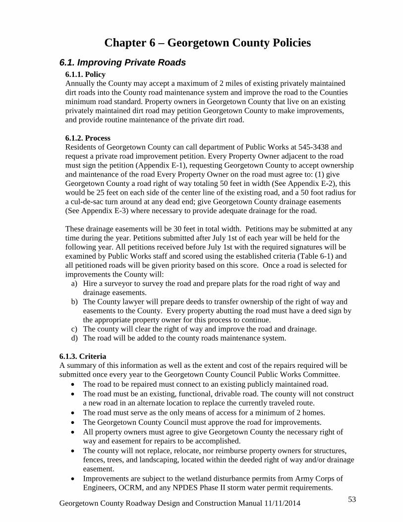
Georgetown County Roadway Design and Construction Manual 11/11/2014
53
Chapter 6 – Georgetown County Policies
6.1. Improving Private Roads 6.1.1. Policy Annually the County may accept a maximum of 2 miles of existing privately maintained dirt roads into the County road maintenance system and improve the road to the Counties minimum road standard. Property owners in Georgetown County that live on an existing privately maintained dirt road may petition Georgetown County to make improvements, and provide routine maintenance of the private dirt road.
6.1.2. Process Residents of Georgetown County can call department of Public Works at 545-3438 and request a private road improvement petition. Every Property Owner adjacent to the road must sign the petition (Appendix E-1), requesting Georgetown County to accept ownership and maintenance of the road Every Property Owner on the road must agree to: (1) give Georgetown County a road right of way totaling 50 feet in width (See Appendix E-2), this would be 25 feet on each side of the center line of the existing road, and a 50 foot radius for a cul-de-sac turn around at any dead end; give Georgetown County drainage easements (See Appendix E-3) where necessary to provide adequate drainage for the road. These drainage easements will be 30 feet in total width. Petitions may be submitted at any time during the year. Petitions submitted after July 1st of each year will be held for the following year. All petitions received before July 1st with the required signatures will be examined by Public Works staff and scored using the established criteria (Table 6-1) and all petitioned roads will be given priority based on this score. Once a road is selected for improvements the County will:
a) Hire a surveyor to survey the road and prepare plats for the road right of way and drainage easements.
b) The County lawyer will prepare deeds to transfer ownership of the right of way and easements to the County. Every property abutting the road must have a deed sign by the appropriate property owner for this process to continue.
c) The county will clear the right of way and improve the road and drainage. d) The road will be added to the county roads maintenance system.
6.1.3. Criteria A summary of this information as well as the extent and cost of the repairs required will be submitted once every year to the Georgetown County Council Public Works Committee.
• The road to be repaired must connect to an existing publicly maintained road. • The road must be an existing, functional, drivable road. The county will not construct
a new road in an alternate location to replace the currently traveled route. • The road must serve as the only means of access for a minimum of 2 homes. • The Georgetown County Council must approve the road for improvements. • All property owners must agree to give Georgetown County the necessary right of
way and easement for repairs to be accomplished. • The county will not replace, relocate, nor reimburse property owners for structures,
fences, trees, and landscaping, located within the deeded right of way and/or drainage easement.
• Improvements are subject to the wetland disturbance permits from Army Corps of Engineers, OCRM, and any NPDES Phase II storm water permit requirements.

Georgetown County Roadway Design and Construction Manual 11/11/2014
54
6.1.4. Liability The owners of the abutting property shall agree to hold harmless the County and its agents, employees, or contractors from any and all liability for damage and/or destruction of structures, trees, and/or landscaping within the deeded right of way and/or easement. Once the improvements are made, the road will become a County Road and placed in the County roads maintenance system. 6.1.5. Funding Road User Fee funds or other specific funds directed by County Council will be utilized for survey, legal support, other fees required for preparing deeds to transfer ownership of right-of-way, easements and to accomplish actual improvements.

Georgetown County Roadway Design and Construction Manual 11/11/2014
55
Table 6 -1 Private Street Improvement Priority Criteria and Methodology
Length in miles 0– 0.5 mi. 5 pts. 0.5 –1.0 mi. 3 pts. > 1.0 mi. 1 pts.
POINTS
Residences Served Access > 20 10 pts. 15 – 20 8 pts. 10 – 15 5 pts. 5 – 10 3 pts. <5 1 pts.
Number of homes per mile >60 30 pts. 51 – 60 25 pts. 41 – 50 20 pts. 31 – 40 15 pts. 21 – 30 10 pts. <21 5 pts.
Estimated cost of improvements < $2,000 20 pts. $2,000 - $8,000 15 pts. $8,000 - $15,000 10 pts. $15,000 - $25,000 5 pts. > $25,000 1 pts.
School age children 10 points added if school age children live on the road
Ambulatory resident 10 points added if ambulatory residents live on the road
Other land uses 10 points applied if the road serves as access to nonresidential
uses (i.e. business, church, nursing home, etc.)
Right-of-way clearance 15 points added if R.O.W. is clear of obstructions
Drainage problem area 15 points applied if no drainage problems are evident
Bridges 15 points applied if there are no bridges present along the road
segment
Wetlands 15 points added if there are no wetlands within or adjacent to
the roadway
Contiguous to a paved street 10 points added if the roadway is abutting a paved road
Connects two paved roads 5 points added if the roadway connects two or more paved
roads
(Maximum number of points = 170) TOTAL _________

Georgetown County Roadway Design and Construction Manual 11/11/2014
56
6.2. Accepting Roads into County Road Maintenance System 6.2.1. Policy Property owner (Developer) may request Georgetown County to accept new and existing roads into the county road maintenance system. The roads and drainage must meet minimum county standards before the county will accept the roads and drainage. 6.2.2. Process All new development plans must be reviewed and approved by the Planning Department, Stormwater Division and the Public Works Division prior to construction. Developer must coordinate all stormwater related inspections with the Stormwater Division at 545-3524. Developer must coordinate all road related inspections as listed below with Public Works at 545-3438. Each step of the construction must be inspected and approved by Georgetown County (See Development Regulation - subdivision Inspection Checklist in Appendix E-5).
• Developer must provide sub grade compaction verified by licensed Geotechnical Firm if requirement exists and/or demonstrate proof roll on sub grade with fully loaded tandem dump truck once the road is on grade.
• Developer must comply with design criteria for thickness of sub base aggregate material. Two inch minimum thickness under all curbing (if applicable).
• Developer must provide base course compaction verified by licensed Geotechnical Firm if requirement exists and/or demonstrate proof roll on base course with fully loaded tandem dump truck once the road is on grade.
• Asphalt inspection is included with final inspection. Developer must provide asphalt design mix specifications from the asphalt plant and core samples of the asphalt to verify asphalt thickness.
• All deficiencies identified during the final inspection must be corrected by the developer before approval is granted
• Engineer for the developer must provide a letter certifying that all infrastructures were constructed according to plans and specifications.
• Attorney for the developer must prepare a deed to right of way for all road right of ways and drainage easements. Right of way for all roads will be a minimum of 50 feet in width and all drainage easements will be a minimum of 20 feet in width.
6.2.3. Criteria All developments must meet the minimum requirements of the Georgetown County Development Regulations; plans must be approved by the Planning Commission. All developments must meet the minimum requirements of the Georgetown County Stormwater Regulations and plans must be approved by the Stormwater Division. All construction must be Inspected and approved by the Georgetown County Public Works Division and the Georgetown County Stormwater Division.
6.2.4. Liability The owners of the adjacent property shall agree to hold harmless the County and Its agents, employees or contractors from any and all liability for damage and/or destruction of structures, trees and landscaping within the deeded right of way and/or easement.

Georgetown County Roadway Design and Construction Manual 11/11/2014
57
Once a road is deeded to Georgetown County the road will be placed in the County roads maintenance system. 6.2.5. Funding All costs associated with construction and dedications are the responsibility of the property owner and/or develop.
6.3. Speed Limits for County Roads 6.3.1. Policy Under SC code 56-5-710 local authorities have limited the authority to change the prima facie speed limits prescribed in SC Code 56-5-1520. This operating procedure specifies how Georgetown County will administer this authority. 6.3.2. Process Residents of Georgetown County can call the department of Public Services at (843) 545-3438 and request a speed limit adjustment petition for County Streets or Roads, See Appendix E-4.
1. Every Property Owner adjacent to the section of street/road that will be impacted by
the proposed change in speed limit must sign the petition requesting Georgetown County to conduct a traffic investigation to determine the maximum speed limit permitted based on State Code and County Subdivision Design Guidance.
2. Information to be provided must include specific information on the designated section of the road to be impacted by speed limit adjustment, Primary point of contact (POC) on the road for addressing questions or information must be the first signature on the petition request. Cover letter citing the reason/justification for requesting the speed limit adjustment must be submitted with the signed petition request before County can take any action.
3. If appropriate attach letter from either Emergency Services or School District supporting the speed limit adjustment request Petitions may be submitted at any time during the year.
All petitions received with the required signatures and necessary supporting documentation will be examined by Public Works Division staff. They will examine the history of the road, consider traffic on the road, school bus and any other municipal vehicle usage, verify the condition of the road, conduct a traffic count if deemed necessary, and identify any existing obstructions or unusual site conditions and review the volume of current pedestrian or bicycle traffic. A written report of these findings will then be submitted to the County Engineer and under the procedure described in SC Code 56-5-1540. To insure that the County has a sound basis for assigning speed limit, the County Engineer will provide the final recommendation for speed limit on the petitioned section of road. The Public Works Division will be responsible for contacting the designated Primary point of contact on the petition and informing that individual what action if any the County will take on the speed limit adjustment request.

Georgetown County Roadway Design and Construction Manual 11/11/2014
58
6.3.3. Criteria "County Street" or "County Road" shall include any and all roads maintained by Georgetown County whether acquired by the County as the result of dedication by deed, plat, or other written instrument and formally accepted by the County or acceptance by the County by maintenance. "Urban District" SC State code specifies this means the territory contiguous to and including any street which is built up with structures devoted to business, industry, or dwelling houses situated at intervals of less than one hundred feet for a distance of a quarter of a mile or more and sets the speed limit at thirty (30) miles an hour. County will use the County Street Design Criteria Appendix Table D-1 as the minimum standard for posted speeds on County roads. 6.3.4. Appeals If a Georgetown County resident who has petitioned for a speed limit change feels that his/her road has not received equitable consideration or questions the decision establishing the recommended speed limit, they can submit a request for reconsideration to the Director of Public Services and their request win be forwarded and addressed by either the County Administrator or County Council, They will determine if an official traffic study by an outside traffic engineering firm is warranted.

Georgetown County Roadway Design and Construction Manual 11/11/2014
59
Definitions: AASHTO American Association of State Highway and Transportation Officials, “A Policy on Geometric Design of Highways and Streets” (current edition). ADT Average Daily Traffic Axle Load The total load transmitted by all wheels on a single axle extending across the full width of the vehicle. Tandem axles 40 inches or less apart shall be considered as a single axle. California Bearing Ratio A measure of the ability of a soil or aggregate to resist the transmission of a vertical load in a lateral direction. Emulsified Asphalt Treated Base A base consisting of a mixture of mineral aggregate and emulsified asphalt spread on a prepared surface to support a surface course. Equivalent Single Axle Loads (ESAL) A numerical factor that expresses the relationship of a given axle load to another axle load in terms of their effect on a serviceability of a pavement structure. All axle loads are equated in terms of the equivalent number of repetitions of an 18,000 pound single axle. 18k EDLA 18,000 pound single axle Equivalent Daily Load Applications (explained in “Axle Load” and “ESAL” above). Flexible Pavement A pavement structure which maintains contact with and distributes loads to the subgrade and depends upon aggregate interlock, particle friction, and cohesion for stability. Flowline The transition point between the gutter and the face of the curb. For a cross or valley pan, it is the center of the pan. Where no curb exists, the flowline will be considered the edge of the outside traveled lane. Grade Rate or percent of change in slope, either ascending or descending from or along the highway. It is measured along the centerline of the highway or access. HOA Homeowner Association HPR Horizontal Property Regime
Georgetown County Roadway Design and Construction Manual 11/11/2014
60
Lime Treated Subgrade Subgrade consisting of a mixture of soil, hydrated lime and water, usually mixed in place and placed to support a pavement structure. MUTCD The Manual on Uniform Traffic Control Devices and the South Carolina Supplement, current editions. Passing Sight Distance The visibility distance required to allow drivers to execute safe passing maneuvers in the opposing traffic lane of a two-lane, two-way highway. Pavement Structure The combination of subbase, base course and surface course placed on a subgrade to support the traffic load and distribute it to the roadbed.
a. Subbase: The layer or layers of specified or selected material of designed thickness placed on a subgrade to support a base course. b. Base Course: The layer or layers of specified or selected material of designed thickness placed on a subbase or subgrade to support a surface course. c. Surface Course: The uppermost component of a pavement structure designed to accommodate the traffic load, the top layer of which resists skidding, traffic abrasion, and the disintegrating effects of climate. The top layer is sometimes called “Wearing Course”.
Plant Mixed Bituminous Base A base consisting of mineral aggregate and bituminous material, mixed in a central plant, laid and compacted while hot, on a subbase or a subgrade, to support a surface course. Plant Mixed Bituminous Pavement A combination of mineral aggregate and bituminous material mixed in a central plant, laid and compacted while hot. POA Property Owners Association Regional Factor A numerical factor expressed as a summation of the values assigned for precipitation, elevation, and drainage. This factor is used to adjust the structural number. Roads Public or private rights-of-way within Georgetown County. SCDOT South Carolina Department of Transportation Serviceability Index A number indicative of the ability of the pavement to serve traffic at any particular time in its design life.

Georgetown County Roadway Design and Construction Manual 11/11/2014
61
Signal Progression Progressive movement of traffic at a planned rate of speed through adjacent signalized locations within a traffic control system without stopping. Soil Support Value A number which expresses the relative ability of a soil or aggregate mixture to support traffic loads through the pavement structure. Speed Change Lane A separate lane for the purpose of enabling a vehicle entering or leaving a roadway to increase (acceleration lane) or decrease (deceleration lane) its speed to a rate at which it can more safely merge or diverge with through traffic. Stabilometer “R” Value A numerical value expressing the ability of a soil or aggregate to resist the transmission of vertical load in a lateral or horizontal direction. Stopping Sight Distance The minimum sight distance necessary to enable a vehicle traveling at or near the design speed to stop before reaching a stationary object in its path. Storage Lane Additional lane footage added to a deceleration lane to store the maximum number of vehicles likely to accumulate during critical periods without interfering with the through lanes. Streets Public or private rights-of-ways within Georgetown County. Strength Coefficient A factor used for expressing the relative strength of each layer in a pavement structure. Structural Number A number derived from an analysis of roadbed and traffic conditions. A Weighted Structural Number is a Structural Number which has been adjusted for environmental conditions. A Weighted Structural Number may be converted to pavement structure thickness through the use of suitable factors related to the type of material being used in the pavement structure. Traffic Analysis Period A common analysis period (usually 20 years) used in geometric design. Untreated Base Course A layer or layers of base course without treatment of any kind.

Appendix A Public Street/Road Templates

Georgetown County Roadway Design and Construction Manual 11/11/2014
1
B
Principal Arterial Street Template 1
Minor Arterial Street Template 2
Collector Street
(36’ FL to FL) with Attached Sidewalks Template 3

Georgetown County Roadway Design and Construction Manual 11/11/2014
2
Collector Streets (36’ FL to FL) with Detached Sidewalks
Template 4
Local Street (28’ FL to FL) with Attached Sidewalks
Template 5
Local Street (28’ FL to FL) with Detached Sidewalks
Template 6
11’-0” 14’-0” 14’-0” 11’-0”
6’-6” 12’-0” 12’-0” 6’-6”
14’ 14’

Georgetown County Roadway Design and Construction Manual 11/11/2014
3
Local Street (26’ FL to FL) with Attached Sidewalks
Template 7
Local Street (26’ FL to FL) with Detached Sidewalks
Template 8
Principal Arterial Road Template 9
12’ 13’ 12’ 13’
11’ 11’ 7’ 7’
28’-0”’
13’-0” 13’-0”
11’-0” 11’-0”
4’ 5’

Georgetown County Roadway Design and Construction Manual 11/11/2014
4
Minor Arterial Road Template 10
Minor Collector Road Template 11
Local Road Template 12
4’ 7’ 7’ 4’ 11’ 11’
11’ 14’ 14’ 11’
4’ 6’ 6’ 4’
7’ 6’ 6’ 7’

Georgetown County Roadway Design and Construction Manual 11/11/2014
5
Cul-de-Sac for Local Streets Template 13

Georgetown County Roadway Design and Construction Manual 11/11/2014
6
Partial Cul-de-Sac for Local Streets Template 14

Georgetown County Roadway Design and Construction Manual 11/11/2014
7
Offset Cul-de-Sac for Local Streets Template 15

Georgetown County Roadway Design and Construction Manual 11/11/2014
8
Cul-de-Sac for Local Roads
Template 16

Georgetown County Roadway Design and Construction Manual 11/11/2014
9
6. ALL WEATHER SURFACE CONSISTS OF 6” COMPACTED SLAG, ROCK OR GRAVEL.
Driveway/Private Street/Road & Non-Maintained Street/Road in County R.O.W. Template 17
Pull Out for Private Street/Road Template 18

Georgetown County Roadway Design and Construction Manual 11/11/2014
10
Hammerhead Turnaround for Private Drive Template 19

Appendix B Standard Construction Details

Standard Detail 1 Curb and Gutter
B
1

Georgetown County Roadway Design and Construction Manual 11/11/2014
2
Standard Detail 2
6” Vertical Curb, Gutter and Attached Sidewalk
Standard Detail 3
6” Vertical Curb, Gutter and Attached Sidewalk

Georgetown County Roadway Design and Construction Manual 11/11/2014
3

Georgetown County Roadway Design and Construction Manual 11/11/2014
4
Standard Detail 5 Curb Ramp Details

Georgetown County Roadway Design and Construction Manual 11/11/2014
5
Standard Detail 6 Curb Ramp Details
IN

Georgetown County Roadway Design and Construction Manual 11/11/2014
6

Georgetown County Roadway Design and Construction Manual 11/11/2014
7
Standard Detail 8 Typical Intersection Crosspan

Georgetown County Roadway Design and Construction Manual 11/11/2014
8
Standard Detail 9 Driveway Section for 6” Vertical Curb and Gutter

Georgetown County Roadway Design and Construction Manual 11/11/2014
9
Standard Detail 10 Optional Driveway Section for Combination Curb,
Gutter and Sidewalk

Georgetown County Roadway Design and Construction Manual 11/11/2014
10
Standard Detail 11 Driveway/Private Road Approaches for Roads

Georgetown County Roadway Design and Construction Manual 11/11/2014
11
Standard Detail 12 Typical Median Designs

Georgetown County Roadway Design and Construction Manual 11/11/2014
12
Standard Detail 13 Concrete Joint Details

Georgetown County Roadway Design and Construction Manual 11/11/2014
13
Standard Detail 14 Asphalt Street/Road Patchback
Standard Detail 15 Road and Street Name Signs

Appendix C Roadway Design Nomographs for Pavements

Georgetown County Roadway Design and Construction Manual 11/11/2014
1
Figure C-1 Design Nomograph for Flexible Pavements Serviceability Index 2.0
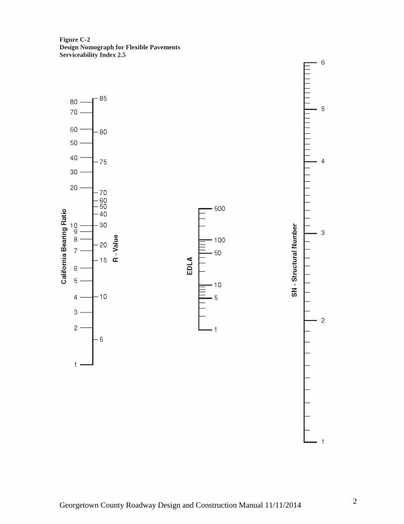
Georgetown County Roadway Design and Construction Manual 11/11/2014
2
Figure C-2 Design Nomograph for Flexible Pavements Serviceability Index 2.5

Georgetown County Roadway Design and Construction Manual 11/11/2014
3
Figure C-3 Design Nomograph for Rigid Pavements Serviceability Index 2.0

Georgetown County Roadway Design and Construction Manual 11/11/2014
4
Figure C-4 Design Nomograph for Rigid Pavements Serviceability Index 2.5

Appendix D Roadway Classifications &
Design Guideline Tables

Georgetown County Roadway Design and Construction Manual 11/11/2014
1
Table D-1 Summary of Minimum Standards for Streets Based on Design Criteria
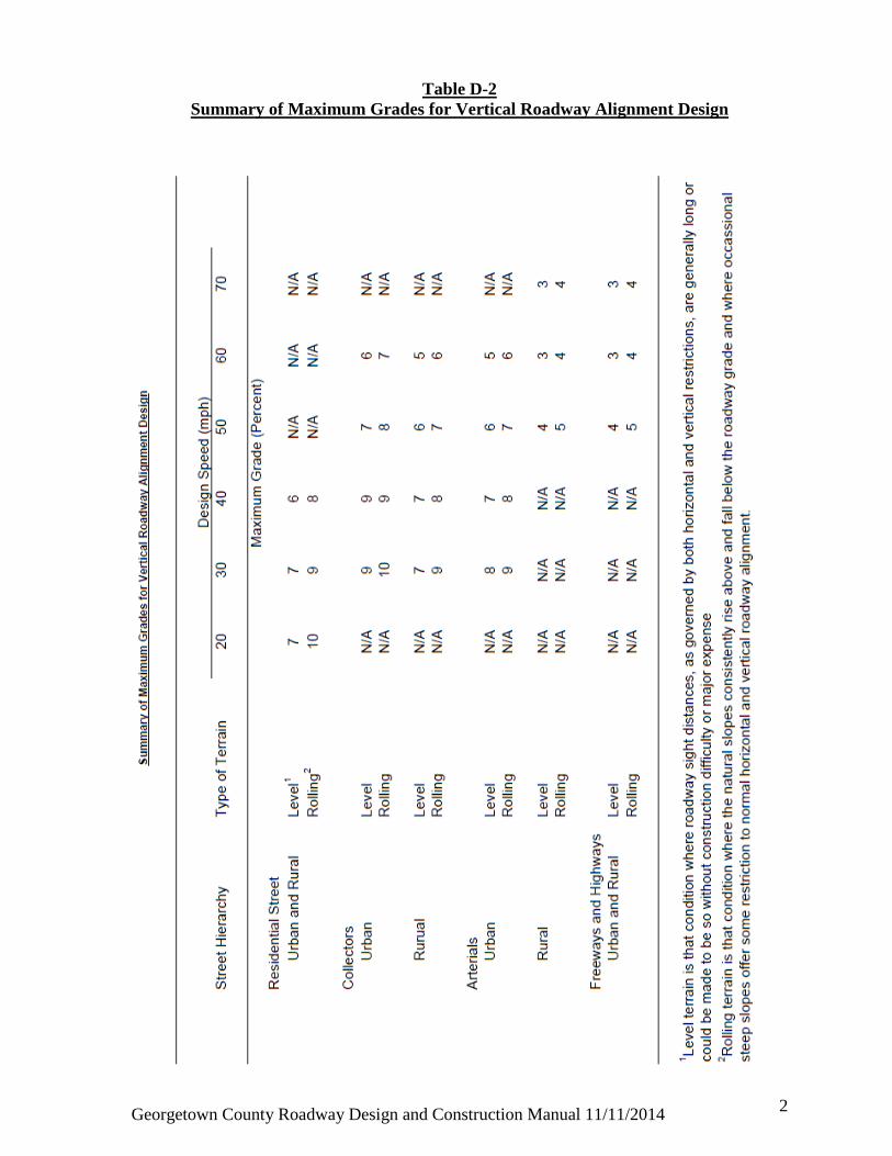
Georgetown County Roadway Design and Construction Manual 11/11/2014
2
Table D-2 Summary of Maximum Grades for Vertical Roadway Alignment Design

Georgetown County Roadway Design and Construction Manual 11/11/2014
3
Table D-3
Street Hierarchy Definitions Access Street lowest order of streets: Also known as a Local Street. Provides frontage for access to lots, and carries traffic having destination or origin on the street itself. Access streets shall be designed so that no section conveys an ADT greater than 500. Sub-collector, middle order street: Provides frontage for access to lots, and carries traffic of adjoining access streets designed to carry somewhat higher traffic volumes with traffic limited to motorist having origin or destination within the immediate neighborhood. Sub-collectors shall be designed so that no section conveys an ADT greater than 2000. Collector, higher order street: Conducts and distributes traffic between lower-order (access/sub-collector) and higher order streets. Function is to promote free traffic flow; therefore, parking and direct access to homes from this level of street is prohibited. Collectors shall be designed so that they do not promote use as a shortcut by non-neighborhood traffic and shall be designed so that no section conveys an ADT greater than 5000. Arterial: Principal traffic artery within residential or commercial areas that carries relatively high traffic volumes and conveys traffic from arterial streets to lower-order streets. Its function is to promote the free flow of traffic; as such, no parking or residences shall be permitted along or have direct access to such roads. ADT’s = 7,000+ *ADT – Average daily trips

Georgetown County Roadway Design and Construction Manual 11/11/2014
4
Table D-4 Trip Generation Rates by Major Land Use Categories

Georgetown County Roadway Design and Construction Manual 11/11/2014
5
Table D-5 Alternate Dead-End Configurations
Varies
Varies Varies
Varies Varies
80’

Appendix E Roadway Forms and Checklists

Georgetown County Roadway Design and Construction Manual 11/11/2014
1
Form E-1 Private or Existing Public Road Petition (STATE OF SOUTH CAROLINA) PETITION (COUNTY OF GEORGETOWN) We, the undersigned residents and property owners, living on __________________________________ in Georgetown County, hereby request (name of road for improvement) Georgetown County to evaluate the referenced road for improvement, which is approximately ___________ mile(s) long. We hereby certify that ___________________ separate dwelling units have
(# of homes) entrances off of this roadway and that school buses [ DO ] or [ DO NOT ] use this roadway. We understand that the County will each year rank according to an approved formula all private roads with valid petitions for improvement and those roads with the highest ranking will be recommended for improvement. The recommended list will be based on anticipated funding levels. Every property owner on the road must agree that (1) he/she wants the road improved, and (2) that he/she will grant (without compensation) any needed right-of-way. We understand that typical road improvements include establishment of a county-standard 2-lane road, excavation of roadside ditches, and creation of a 50’ public right-of-way. Unless every property owner agrees to the improvement and granting of rights-of-way, the road may not be considered. NAME ADDRESS TELEPHONE # DATE ________________________________________________________________________ ________________________________________________________________________ ________________________________________________________________________ ________________________________________________________________________ ________________________________________________________________________ ________________________________________________________________________ ________________________________________________________________________ ________________________________________________________________________ ________________________________________________________________________ ________________________________________________________________________ ________________________________________________________________________ ________________________________________________________________________ ________________________________________________________________________ ________________________________________________________________________ ________________________________________________________________________ ________________________________________________________________________
Return Petition To: Georgetown County
Department of Public Services P. O. Box 421270
Georgetown, SC 29442-1270

Georgetown County Roadway Design and Construction Manual 11/11/2014
2
Form E-2 Right-of-Way Dedication STATE OF SOUTH CAROLINA ) ) EASEMENT FOR RIGHT-OF-WAY COUNTY OF GEORGETOWN ) KNOW ALL MEN BY THESE PRESENTS that
________________________________ (hereinafter called the "Grantor(s)"), under the laws
of the State of South Carolina, in consideration of the sum of ONE DOLLAR ($1.00) to it in
hand paid, and other valuable considerations, at and before the sealing and delivery hereof,
by Georgetown County, South Carolina, the receipt of which is hereby acknowledged, has
granted, bargained, sold and released, and by these presents does grant, bargain, sell and
release unto the said Georgetown County, South Carolina, (hereinafter called the
"Grantee") its successors or assigns, a perpetual right-of-way easement _______ feet (___’)
in total width beginning at the centerline of the existing _______ and lying in on, over, and
across the following described real property in order to allow the said Grantee to construct
and/or maintain __________________, and also to construct or assign the right of
construction within said right-of-way for utilities, including but not limited to water, sewer,
storm water drainage and lines, power, cable television and telephone lines above or beneath
the ground, located over and across that parcel of land more particularly described as follows
(hereinafter referred to as the "Easement Premises"):
DESCRIPTION
See attached exhibit “A”
Tax Map No.: _____________________________________________
TOGETHER with all and singular the rights, members, hereditaments and
appurtenances thereunto belonging or in anywise incident or appurtenant thereto.
TO HAVE AND TO HOLD all and singular the said right-of-way and rights
hereinabove granted unto Georgetown County, South Carolina, its successors or assigns,
forever.

Georgetown County Roadway Design and Construction Manual 11/11/2014
3
IN WITNESS WHEREOF, the undersigned, have hereunto set their hands and seals
this _____day of ____________, 20__.
Signed, Sealed and Delivered Grantor(s): in the presence of: (Witness #1) _________________________________ (Witness #2/Notary) STATE OF SOUTH CAROLINA ) COUNTY OF GEORGETOWN )
PERSONALLY appeared before me the undersigned witness and made oath that s/he saw the within named grantors sign, seal and, as his/her/their act and deed, deliver the within Easement and that s/he along with the other subscribing witnesses witnessed the execution thereof.
(Witness #1) Sworn to before me this _____ day of ___________, 20__ (Notary/Witness #2 from above) Notary Public for My Commission Expires:

Georgetown County Roadway Design and Construction Manual 11/11/2014
4
STATE OF SOUTH CAROLINA ) ) ACCEPTANCE COUNTY OF GEORGETOWN )
The street and/or road described in the within easement for right-of-way is hereby
accepted, and the recording of this easement authorized, this _____day of __________, 20__.
GEORGETOWN COUNTY, SOUTH CAROLINA
BY (Notary) County Administrator (Witness) STATE OF SOUTH CAROLINA ) ACKNOWLEDGMENT COUNTY OF GEORGETOWN )
THE foregoing instrument was acknowledged before me this _____ day of ___________, 20__ by GEORGETOWN COUNTY ADMINISTRATOR Notary Public for South Carolina (Notary from above) My Commission Expires: Grantee's Address: Georgetown County Attn: County Attorney Post Office Drawer 421270 Georgetown, SC 29442

Georgetown County Roadway Design and Construction Manual 11/11/2014
5
Form E-3 Drainage Easement Dedication STATE OF SOUTH CAROLINA ) ) EASEMENT FOR DRAINAGE COUNTY OF GEORGETOWN )
KNOW ALL MEN BY THESE PRESENTS that ___________________________.,
(hereinafter called the "Grantor"), under the laws of the State of South Carolina, in
consideration of the sum of ONE DOLLAR ($1.00) to it in hand paid, and other valuable
considerations, at and before the sealing and delivery hereof, by Georgetown County, South
Carolina, the receipt of which is hereby acknowledged, has granted, bargained, sold and
released, and by these presents does grant, bargain, sell and release unto the said
Georgetown County, South Carolina, (hereinafter called the "Grantee") its successors or
assigns, a drainage easement _______ (___') in width beginning at ____________________,
on, over, and across the following described real property in order to allow the said Grantee
to construct and/or maintain a drainage system, including ditches, drainage pipes, catch
basins and appurtenances, located over and across that parcel of land more particularly
described as follows (hereinafter referred to as the "Easement Premises"):
DESCRIPTION
See attached Exhibit “A”
Tax Map No.: ______________
TOGETHER with all and singular the rights, members, hereditaments and
appurtenances thereunto belonging or in anywise incident or appurtenant thereto.
TO HAVE AND TO HOLD all and singular the said drainage easement and rights
hereinabove granted unto Georgetown County, South Carolina, its successors or assigns,
forever.

Georgetown County Roadway Design and Construction Manual 11/11/2014
6
IN WITNESS WHEREOF, the undersigned, have hereunto set their hands and seals
this _____day of ____________, 20__.
Signed, Sealed and Delivered Grantor(s): in the presence of: (Witness #1) (Witness #2/Notary) STATE OF SOUTH CAROLINA ) COUNTY OF GEORGETOWN )
PERSONALLY appeared before me the undersigned witness and made oath that s/he saw the within named grantors sign, seal and, as his/her/their act and deed, deliver the within Easement and that s/he along with the other subscribing witnesses witnessed the execution thereof.
(Witness #1) Sworn to before me this _____ day of ___________, 20__ (Notary/Witness #2 from above) Notary Public for My Commission Expires:

Georgetown County Roadway Design and Construction Manual 11/11/2014
7
STATE OF SOUTH CAROLINA ) ) ACCEPTANCE COUNTY OF GEORGETOWN )
The drainage system described in the within easement for drainage is hereby
accepted, and the recording of this easement authorized, this _____day of __________, 20__.
GEORGETOWN COUNTY, SOUTH CAROLINA
BY (Notary) County Administrator (Witness) STATE OF SOUTH CAROLINA ) ACKNOWLEDGMENT COUNTY OF GEORGETOWN )
THE foregoing instrument was acknowledged before me this _____ day of ___________, 20__ by GEORGETOWN COUNTY ADMINISTRATOR ____________________________. Notary Public for South Carolina (Notary from above) My Commission Expires: Grantee's Address: Georgetown County Attn: County Attorney Post Office Drawer 421270 Georgetown, SC 29442

Georgetown County Roadway Design and Construction Manual 11/11/2014
8
Form E-4 SPEED LIMIT ADJUSTMENT PETITION (COUNTY OF GEORGETOWN) We, the undersigned residents and property owners, living on _________________________________________________________ in Georgetown County, hereby request (Name of road/street) Georgetown County establishes a special speed zone, based on an engineering and traffic study. We further request that the posted speed be set at ______ Miles Per Hour (MPH) for the section of the road between ___________________________________________________________________________________ (List start & end address, plats, or intersections of requested speed change) We understand that the County will determine if a speed limit adjustment is warranted based on an in-house engineering and traffic study. The investigator will consider the following factors in making a determination: type of road, existing right-of-way, width of road shoulders, line of sight visibility, type and volume of traffic flow, any existing obstructions or unusual site conditions, type and amount of current pedestrian or bicycle traffic along the section of road specified and any other significant factors listed in this petition. Current speed limit for various street classifications can be found in Table D-1 of Appendix D of the Roadway Design and Construction Manual. Every property owner on the section of the road impacted by any adjustment in the speed limit must agree that (1) he/she wants the speed limit adjusted and (2) that he/she gives permission for the county to post speed signage on their property if sufficient County right-of-way does not exist to safely post speed limit signage. Unless every property owner agrees to these conditions the speed limit adjustment petition may not be considered. NAME ADDRESS TELEPHONE # DATE ______________________________________________________________________________________ (Primary Point of Contact for this request)
______________________________________________________________________________________ ______________________________________________________________________________________ ________________________________________________________________________________________________ ________________________________________________________________________________________________ ________________________________________________________________________________________________ ________________________________________________________________________________________________ Return Petition To: Georgetown County Department of Public Services P. O. Box 421270 Georgetown, SC 29442-1270

Georgetown County Roadway Design and Construction Manual 11/11/2014
9
Form E-5
SUBDIVISION STREET INSPECTION CHECKLIST