Embed Size (px)
Citation preview

Temescal Canyon Road Widening Projects Dawson Canyon Road to 0.7 Mile North
Dos Lagos Drive to Leroy Road, and Temescal Canyon Road Slurry Seal Project
0.7 Miles North of Dawson Canyon Road to Leroy Road Project No. C5-0072, C6-0066,
State Project No. LPPSB1L-5956(267); and Temescal Canyon Road Drainage Improvement Project
At Coldwater Creek Project No. B9-0988
In the Community of Temescal Valley
Geotechnical Design Report Temescal Canyon Rd Widening – Dos Lagos Segment Dated September 23, 2016 (minor revisions April 13, 2018) Notice regarding this Report: This report is provided for reference only.
Although this information represents the latest information available, the County of Riverside Transportation Department does not guarantee the accuracy of this data.

A Report Prepared for: NCM Engineering Corp. 4740 Green River Road, Suite 218 Corona, CA 92880 GEOTECHNICAL REPORT TEMESCAL CANYON ROAD WIDENING DOS LAGOS SEGMENT COUNTY OF RIVERSIDE, CALIFORNIA Project No. 2016-016 by Thiyagarajah Sutharsan, PhD, Civil Engineer 86768 by Clint Isa Civil Engineer 76470
DiazYourman & Associates 1616 East 17th Street Santa Ana, CA 92705-8509 (714) 245-2920 September 23 2016 (minor revisions April 13, 2018)
D I A Z Y O U R M A N& A S S O C I AT E S
1616 EAST 17th STREET SANTA ANA, CA 92705-8509 TEL. (714) 245-2920 FAX (714) 245-2950
SUPPLEMENTAL PROJECT INFORMATION, GEOTECH REPORT, DOS LAGOS SEGMENT, SHEET 1 of 41

i
K:\datafls\PROJECTS\2016\2016-016\Report\2016-016 Dos Lagos Segment v2.docx
TABLE OF CONTENTS
1 INTRODUCTION ............................................................................................................... 1
2 DATA REVIEW, FIELD EXPLORATION, AND LABORATORY TESTING ......................... 4
3 SITE CONDITIONS ........................................................................................................... 5
SURFACE CONDITIONS ............................................................................................ 5 3.1
SUBSURFACE CONDITIONS ..................................................................................... 6 3.2
4 CONCLUSIONS AND RECOMMENDATIONS .................................................................. 7
PAVEMENT THICKNESS DESIGN ............................................................................. 7 4.1
EARTHWORK ............................................................................................................. 9 4.2
UTILITY TRENCHES..................................................................................................11 4.3
CORROSION POTENTIAL .........................................................................................12 4.4
5 PLAN REVIEW, CONSTRUCTION OBSERVATION, AND TESTING ..............................14
6 LIMITATIONS ...................................................................................................................15
7 BIBLIOGRAPHY...............................................................................................................16
LIST OF TABLES
Table 1 - SUBSURFACE SOIL CHARACTERISTICS ................................................................ 6 Table 2 - IMPORT FILL CRITERIA ...........................................................................................10 Table 3 - CORROSION POTENTIAL ........................................................................................13
LIST OF FIGURES
Figure 1 - VICINITY MAP ........................................................................................................... 1 Figure 2 - SITE PLAN ................................................................................................................ 2 Figure 3 - PAVEMENT THICKNESS .......................................................................................... 8 Figure 4 - PIPELINE BACKFILL SCHEMATIC ..........................................................................12
LIST OF APPENDICES
FIELD EXPLORATION APPENDIX A -
LABORATORY TESTING APPENDIX B -
SUPPLEMENTAL PROJECT INFORMATION, GEOTECH REPORT, DOS LAGOS SEGMENT, SHEET 2 of 41

1
K:\datafls\PROJECTS\2016\2016-016\Report\2016-016 Dos Lagos Segment v2.docx
1 INTRODUCTION
This report presents the results of the geotechnical services performed by DiazYourman &
Associates (DYA) for the Dos Lagos Segment of the proposed Temescal Canyon Road
Widening in Corona, County of Riverside, California (Project). NCM Engineering Corporation
authorized this work with a written contract on April 22, 2016.
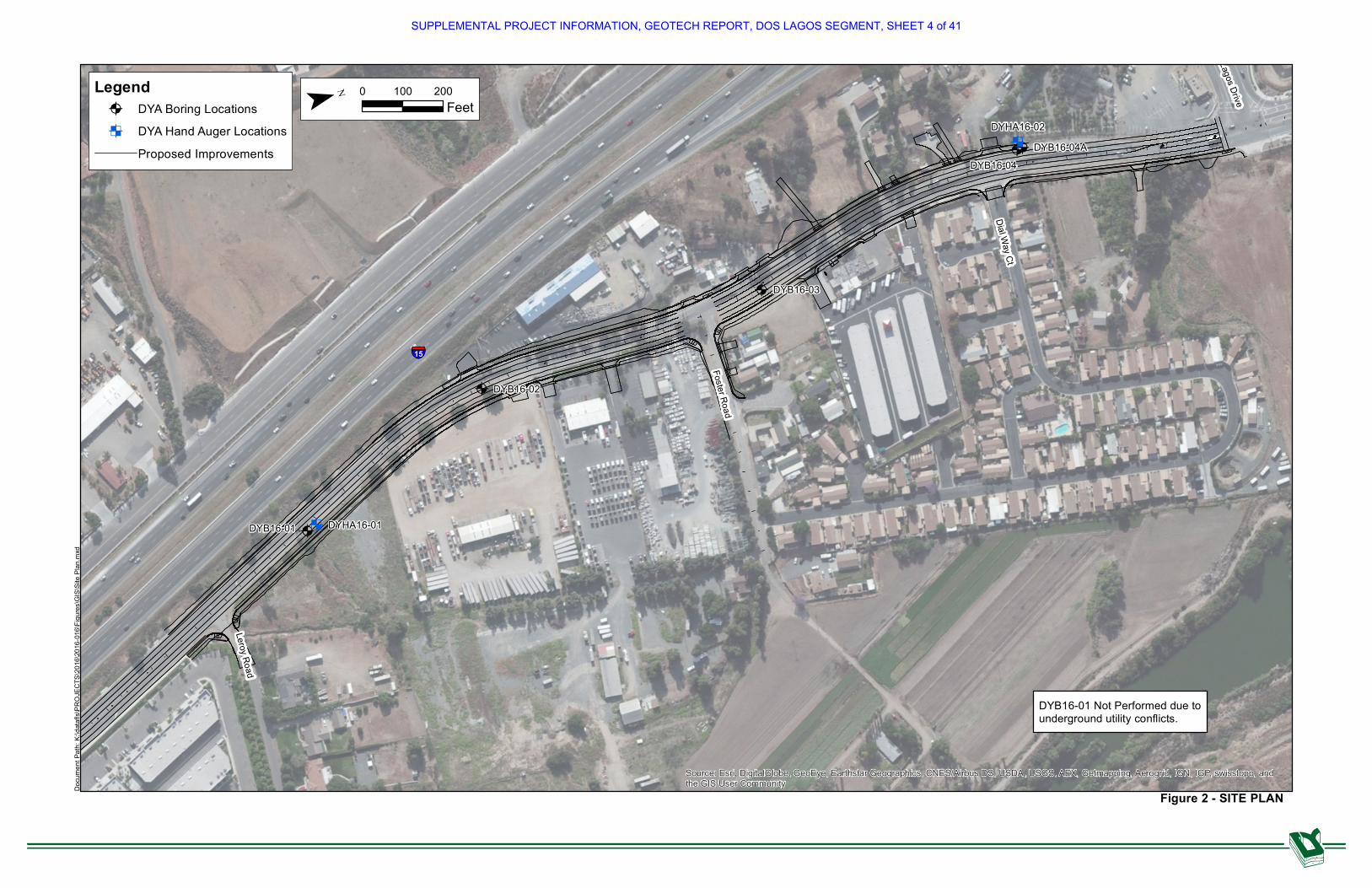
The Project reach consists of the approximately 0.6-mile-long segment of Temescal Canyon
Road located between Dos Lagos Drive and Leroy Road, as shown on the Vicinity Map, Figure
1. Along the Project reach, Temescal Canyon Road provides one lane of traffic in each
direction; we understand that the County of Riverside proposes to widen and slightly realign
Temescal Canyon Road at the site to provide two travel lanes in each direction to match the
four-lane roadway facilities north and south of the Project. The approximate layout of the
proposed Project is shown on the Site Plan, Figure 2.
Figure 1 - VICINITY MAP
SUPPLEMENTAL PROJECT INFORMATION, GEOTECH REPORT, DOS LAGOS SEGMENT, SHEET 3 of 41
Foster Road
Leroy Road
Dial Way Ct
Dos Lagos Drive
15
DYB16-01
DYB16-04A
DYB16-02
DYB16-03
DYB16-04
DYHA16-01
DYHA16-02
Source: Esri, DigitalGlobe, GeoEye, Earthstar Geographics, CNES/Airbus DS, USDA, USGS, AEX, Getmapping, Aerogrid, IGN, IGP, swisstopo, andthe GIS User Community
Figure 2 - SITE PLANDocu
ment
Path:
K:\da
tafls\
PROJ
ECTS
\2016
\2016
-016\F
igures
\GIS\
Site P
lan.m
xdLegend
DYA Boring LocationsDYA Hand Auger LocationsProposed Improvements
0 200100Feet
DYB16-01 Not Performed due tounderground utility conflicts.
SUPPLEMENTAL PROJECT INFORMATION, GEOTECH REPORT, DOS LAGOS SEGMENT, SHEET 4 of 41

3
K:\datafls\PROJECTS\2016\2016-016\Report\2016-016 Dos Lagos Segment v2.docx
The proposed improvements will include two 12-foot-wide lanes and an 8-foot-wide bike lane in
each direction, along with a center 12-foot two-way left-turn lane (painted median). The Project
will also consist of constructing new concrete curbs and gutters; reconstructing driveway and
street tie-ins; constructing ADA-compliant curb ramps; and relocating existing utilities. In
addition, a 6-foot-wide curb-adjacent sidewalk might be constructed on one or both sides of the
street.
The purpose of DYA's investigation was to provide geotechnical input for the design of the
proposed Project. The scope of our services consisted of the following:
Reviewing existing data.
Conducting a subsurface investigation.
Performing laboratory tests on selected soil samples.
Performing engineering analyses to develop conclusions and recommendations
regarding the following:
o Subsurface conditions
o Site preparation and grading
o Pavement thickness for new pavements
o Soil corrosion potential
Preparing this report.
Performing non-destructive testing, such as falling-weight deflectometer testing, for evaluation
of pavement rehabilitation options was outside DYA’s scope of services.
SUPPLEMENTAL PROJECT INFORMATION, GEOTECH REPORT, DOS LAGOS SEGMENT, SHEET 5 of 41

4
K:\datafls\PROJECTS\2016\2016-016\Report\2016-016 Dos Lagos Segment v2.docx
2 DATA REVIEW, FIELD EXPLORATION, AND LABORATORY TESTING
Subsurface data from the Project vicinity presented in previous reports by others were reviewed
to supplement site data collected during this exploration. A list of the documents reviewed is
presented in the bibliography (Section 7).
The field exploration, which was conducted on July 18 and August 10, 2016, consisted of drilling
six soil borings using hollow-stem-auger and hand-auger drilling techniques at the locations
shown on Figure 2. The boring locations were chosen to provide areal coverage of the Project
site for grading and pavement design based on site access restrictions. The boring depths
ranged from approximately 1 to 6.5 feet below the ground surface. Details of the field
exploration, including sampling procedures and boring logs, are presented in Appendix A.
Soil samples collected from the borings were re-examined in the laboratory to substantiate field
classifications. Selected soil samples were tested for moisture content, dry density, grain-size
distribution, percent passing the No. 200 sieve, Atterberg limits, compaction characteristics,
sand equivalent, pavement-supporting capacity (R-value), and corrosion potential (pH, electrical
resistivity, soluble chlorides, and soluble sulfates). The soil samples tested are identified on the
boring logs. Laboratory test data are summarized on the boring logs in Appendix A and
presented on individual test reports in Appendix B.
SUPPLEMENTAL PROJECT INFORMATION, GEOTECH REPORT, DOS LAGOS SEGMENT, SHEET 6 of 41

5
K:\datafls\PROJECTS\2016\2016-016\Report\2016-016 Dos Lagos Segment v2.docx
3 SITE CONDITIONS
SURFACE CONDITIONS 3.1
Along the Project reach, Temescal Canyon Road consisted of an asphalt concrete- (AC-) paved
roadway providing one lane of traffic in each direction. A left-turn lane from the northbound
direction was observed at the intersection of Temescal Canyon with Dos Lagos Drive. Left-turn
lanes from the northbound and southbound directions were also observed at the intersection
located approximately 600 feet south of Dos Lagos Drive.
The condition of the existing AC pavement surface generally varied from poor to fair and
exhibited some signs of distress, including transverse, longitudinal, and alligator cracking and
patching. The thickness of the existing pavement structural section consisted of approximately
6 inches of AC underlain by approximately 7 inches of base; however, it should be noted that
the pavement section thickness was evaluated only near the northern terminus of the Project
reach because of site access restrictions. See Section 3.2 regarding possibility of abandoned
concrete pavement beneath the existing AC pavement surface.
At the time of our field exploration, topography along Temescal Canyon Road was generally flat
and sloped for drainage. Elevations ranged from a maximum of 913 feet near the intersection of
Temescal Canyon Road and Leroy Road to a minimum of 881 feet near the intersection of
Temescal Canyon Road and Dos Lagos Drive.
AC-paved shoulders of varying width were present along most of the Project reach; concrete
sidewalks, curbs, and gutters were partially present east and west of Temescal Canyon Road
along the northern ⅓ of the Project reach. Adjacent land usage to the east and west consisted
primarily of commercial and some residential properties along the middle ½ of the Project reach.
An existing nursery was present to the east and west of Temescal Canyon Road along the
northern ¼ of the Project reach, with generally undeveloped properties along the southern ¼ of
the Project reach. Embankments of varying height and inclination ascended from Temescal
Canyon Road to the west along portions of the Project reach. Numerous large trees were
observed along the east and west shoulders of Temescal Canyon Road along the entire Project
reach.
SUPPLEMENTAL PROJECT INFORMATION, GEOTECH REPORT, DOS LAGOS SEGMENT, SHEET 7 of 41

6
K:\datafls\PROJECTS\2016\2016-016\Report\2016-016 Dos Lagos Segment v2.docx
SUBSURFACE CONDITIONS 3.2
The subgrade soils consisted primarily of loose to medium-dense silty and clayey sands along
the entire Project reach. The in situ and optimum moisture contents, in situ and maximum unit
weights, relative compaction1, and R-values of the subsurface materials are summarized in
Table 1. Groundwater was not encountered during drilling operations.
Table 1 - SUBSURFACE SOIL CHARACTERISTICS
BORING ID DEPTH (feet)
SOIL TYPE
IN SITU MOISTURE CONTENT
1
(%)
OPTIMUM MOISTURE CONTENT
1
(%)
IN SITU DRY UNIT WEIGHT
1
(pcf)
MAXIMUM DRY UNIT WEIGHT
1
(pcf)
RELATIVE COMPACTION
(%) R-
VALUE
DYB16-02 2 SM 3 6 102 135 76 NP
DYB16-02 5 SM 3 6 107 135 79
DYB16-03 1 SM 2 6 116 135 86 38
DYB16-03 4 SM 4 6 113 135 84
DYHA16-02 3.25 SC 8.3 NP 122 NP -- 49
Note(s):
1. Based on results of laboratory testing presented on boring logs in Appendix A and individual laboratory test results presented in Appendix B.
SM = silty sand; SC = clayey sand
NP = not performed
pcf = pounds per cubic foot
As discussed in Appendix A, a concrete obstruction was encountered directly below the existing
pavement section in borings DYB16-04 and DYB16-04A. DYA was not able to identify the
obstruction in the field, nor could we evaluate its thickness or lateral extents. Based on the
findings of the rest of our field exploration, we judge that the obstruction can likely be attributed
to abandoned pavements that are likely associated with a former state highway with an
alignment similar to that of the current Temescal Canyon Road. The County of Riverside
Transportation and Land Management Department (County) published a materials report (2012)
documenting the findings of pavement corings and ground penetrating radar (GPR) surveys
performed along the northern 1/3 of the Project reach. The findings of the corings and GPR
surveys indicated that alignment of the former state highway likely coincided with the existing
southbound lane of Temescal Canyon Road and was likely 18 to 20 feet wide and composed of
Portland cement concrete (PCC).
1 Relative compaction refers to the in-place dry density of soil expressed as a percentage of the maximum dry density of the same
material, as determined by the ASTM International (ASTM) D1557 test method. Optimum moisture content is the moisture content corresponding to the maximum dry density, as determined by the ASTM D1557 test method.
SUPPLEMENTAL PROJECT INFORMATION, GEOTECH REPORT, DOS LAGOS SEGMENT, SHEET 8 of 41

7
K:\datafls\PROJECTS\2016\2016-016\Report\2016-016 Dos Lagos Segment v2.docx
4 CONCLUSIONS AND RECOMMENDATIONS
Based on geotechnical considerations, the on-site soils can support the proposed
improvements. The primary construction consideration is the potential presence of old concrete
pavements beneath some to all of the existing AC pavements along the Project reach. The
potential presence of the old concrete pavements could result in changed conditions during
construction because the lateral extents and thickness of the old concrete pavements are not
well defined at this time. We recommend that additional evaluations be performed to better
identify the footprint and thickness of the old concrete pavements. In addition, the contract
documents should alert the contractor to the potential presence of old concrete pavements
underneath the existing pavements.
PAVEMENT THICKNESS DESIGN 4.1
Recommended minimum dense-graded hot-mix asphalt (HMA) and PCC pavement sections are
presented on Figure 3. The recommended minimum pavement sections are based on the
following:
R-value of 38.
Caltrans design method.
Traffic index (TI) of 10.5, based on information provided by NCM Engineering
Corporation (2016) for Temescal Canyon Road.
The minimum thickness of compacted basement soil and aggregate base (AB) are outlined on
Figure 3. Prior to placing the AB, the basement soils should be firm, hard, and unyielding, and
should not “pump” under the loads of the construction and paving equipment. The basement
soil (subgrade) and AB should be compacted to at least 95% relative compaction. The AB
requirements and specifications are outlined on Figure 3.
SUPPLEMENTAL PROJECT INFORMATION, GEOTECH REPORT, DOS LAGOS SEGMENT, SHEET 9 of 41

8
K:\datafls\PROJECTS\2016\2016-016\Report\2016-016 Dos Lagos Segment v2.docx
Subgrade
Total Pavement Section
ARHM/HMA/PCC Course
Base Course
Basement Soil
COURSE
MINIMUM THICKNESS (inches)
ARHM/HMA/AB HMA/AB Full-Depth HMA PCC/AB
ARHM1 2 -- -- --
HMA2 6 8 14 --
PCC2
-- -- -- 12
Base3
10 10 -- 16
Basement Soil4
12 12 12 12
Note(s):
1. Asphalt rubber hot mix (ARHM) should satisfy the requirements of Greenbook Sections 203 or Caltrans Standard Specifications Section 39. Please note that Caltrans refers to ARHM as rubber hot mix asphalt (RHMA).
2. Dense-graded HMA and PCC should satisfy the requirements of Caltrans Standard Specifications Sections 39 and 40, respectively, or Greenbook Sections 203, and 201 and 302, respectively. Thickness shown for PCC is for doweled pavement.
3. Base course = AB or crushed miscellaneous base (CMB), in accordance with Caltrans Standard Specifications Section 26 or Greenbook Section 200, respectively. The minimum relative compaction is 95%.
4. Compacted in-place natural basement soil or fill; at least 95% relative compaction.
Figure 3 - PAVEMENT THICKNESS
Generally, rigid PCC pavement costs more for initial construction but requires less maintenance
than flexible HMA pavement. For heavy wheel loads along limited alignments, queuing areas,
turning areas, dolly pads, bus stops, and refuse pickup areas, PCC pavement is preferred. For
PCC pavements, the following should be considered:
Construct pavements in a 15-foot square grid or smaller (20 foot rectangular areas if a
square is not practical).
Expansion joints should extend the full depth of the pavement.
Potential joints depth of ¼ of the pavement thickness.
Cure for a minimum of 7 days.
No traffic until the compressive strength exceeds 2,000 pounds per square inch (psi).
SUPPLEMENTAL PROJECT INFORMATION, GEOTECH REPORT, DOS LAGOS SEGMENT, SHEET 10 of 41

9
K:\datafls\PROJECTS\2016\2016-016\Report\2016-016 Dos Lagos Segment v2.docx
Minimum compressive strength of 3,000 psi.
Dowels to strengthen joints.
Minimum slope of 1%.
The dense-graded HMA and PCC layers should not be replaced with open-graded asphalt
concrete (OGAC) and pervious PCC, respectively, to provide a fully permeable pavement. A
separate design is recommended for fully permeable pavements.
EARTHWORK 4.2
Prior to the start of construction, the following should be performed:
All utilities should be located in the field and rerouted, removed, abandoned, or
protected.
Areas should be graded to the planned subgrade elevation.
Reconstructing the road segments may require removing some or all of the existing
pavements and base materials.
The excavated AC and base materials should be taken to a recycling plant.
Unpaved areas to be graded and paved should initially be stripped of all vegetation and
debris, and the material should be removed from the site. Stripping should include root
bulbs associated with existing trees and other landscaping that will be removed to
accommodate the proposed improvements. Clearing of such bulbs and portions thereof
should include roots larger than ½ inch in diameter.
The lateral extents and thickness of the old concrete pavements discussed in Section
3.2 should be further evaluated as-needed.
Prior to placing fill, the exposed subgrade should be:
Scarified to a depth of 8 inches.
Moisture-conditioned to above optimum moisture content.
Compacted to at least 95% relative compaction (or to 90% as indicated elsewhere in the
report).
SUPPLEMENTAL PROJECT INFORMATION, GEOTECH REPORT, DOS LAGOS SEGMENT, SHEET 11 of 41

10
K:\datafls\PROJECTS\2016\2016-016\Report\2016-016 Dos Lagos Segment v2.docx
Fill should be compacted by:
Placing in loose layers less than 8 inches thick.
Moisture-conditioning to above optimum moisture content.
Compacting to at least 95% relative compaction (or to 90% as indicated elsewhere in the
report).
The compacted subgrade soils should be firm, hard, and unyielding.
Import materials (if required) for fill should meet the criteria in Table 2.
Table 2 - IMPORT FILL CRITERIA
CRITERIA IMPORT FILL
Caltrans Specification Section1 19-6.02
Maximum particle size (inches) 3
Maximum liquid limit (%) 30
Maximum plasticity index (%) 10
Maximum percentage passing the #200 sieve (%) 30
R-value 38
1. The fills and backfill shall meet the specified Caltrans (Caltrans, 2015a)/Greenbook (Building News, 2015) criteria and the additional recommendations provided in this table.
Concrete flatwork (i.e., slabs-on-grade, sidewalks, hardscape, curbs, and gutters) should be
underlain by a minimum of 12 inches of compacted engineered soil. The recommended
minimum compaction is 95% but can be reduced to 90% underneath the non-load bearing
elements such as sidewalks in accordance with County of Riverside guidelines (NCM, 2018).
Site grading may be accomplished with conventional heavy-duty construction equipment. The
fill should be compacted using soil compactors designed for compaction as defined by the
Caterpillar Performance Handbook (2016), or equivalent. However, to avoid overstressing
existing buildings, culvert, or other structures backfill adjacent to these existing structures may
need to be compacted using lightweight compaction equipment.
The stability of temporary excavations is a function of several factors, including the total time the
excavation is exposed, moisture condition, soil type and consistency, and contractor's
operations. The contractor is responsible for excavation safety. As a guideline, temporary
construction excavations greater than 3 feet but less than 10 feet deep should be planned with
slopes no steeper than 1.5H:1V (horizontal to vertical). For steeper temporary construction
SUPPLEMENTAL PROJECT INFORMATION, GEOTECH REPORT, DOS LAGOS SEGMENT, SHEET 12 of 41

11
K:\datafls\PROJECTS\2016\2016-016\Report\2016-016 Dos Lagos Segment v2.docx
slopes or deeper excavations, shoring should be provided for stability and protection. The
contractor should strictly adhere to grading requirements of County of Riverside and applicable
health and safety regulations, including those of the Occupational Safety and Health
Administration (OSHA, 2016).
UTILITY TRENCHES 4.3
Utility trenches (either open or backfilled) that parallel structures, pavement, or flatwork should
be planned so that they do not extend below a plane with a downward slope of 1.5H:1V from the
bottom edge of footings, pavement, or flatwork. Temporary shoring to provide footing,
pavement, flatwork, or utility support is recommended unless localized settlements on the order
of 1% of the trench depth can be tolerated.
All excavations should comply with appropriate safety standards outlined in Section 4.2.
Utility pipes should be placed on the bottom of a neatly cut trench on a layer of bedding as
outlined on Figure 4 or according to the manufacturer's recommendations, whichever is more
stringent. Jetting should not be allowed for compaction purposes. The materials encountered
in the field should be checked for suitability as bedding material in accordance with the Caltrans
(2015a) and Greenbook (Building News, 2015) specifications shown on Figure 4. Based on the
laboratory test results presented in Appendix B, we anticipate that the near-surface sandy soils
will be suitable for reuse as trench backfill. The near-surface sandy soils should be tested to
check whether they meet the criteria for bedding soils.
To expedite construction, import materials or controlled low-strength material (CLSM, i.e.,
“slurry”) can be used as trench zone backfill. Where used, import fills should satisfy the criteria
in Table 2. In general, CLSM should satisfy the criteria of Section 201-6 of the Greenbook
(Building News, 2015) or Caltrans Specification Section 19-3.02G (Caltrans, 2015a); however,
when used within the upper 2 feet of trench zone backfill (dimension E on Figure 4) CLSM
should consist of a minimum of 100 pounds of cement per cubic yard (approximate equivalent of
1-sack slurry). Where approved by the manufacturer, CLSM can also be used as bedding or
within pipe zone.
SUPPLEMENTAL PROJECT INFORMATION, GEOTECH REPORT, DOS LAGOS SEGMENT, SHEET 13 of 41

12
K:\datafls\PROJECTS\2016\2016-016\Report\2016-016 Dos Lagos Segment v2.docx
Trench Zone Backfill
Not to Scale
PAVEMENT SECTION
Trench Zone Backfill
A
Pipe Bedding
D
E
See Figure 3 for Pavement Section Details
C
B
F
MATERIAL
MINIMUM THICKNESS
(feet)
MIIMUM RELATIVE COMPACTION
1
(%)
BACKFILL SPECIFICATIONS
Caltrans Specifications Greenbook Specifications
Pipe Bedding A = 0.33 for B<4.5’ and 0.5’ for B>4.5
-- 19-3.02F 306-6
Pipe Zone C = 1 -- 19-3.02F 306-6
Trench Zone D varies 902 -- --
Trench Zone3 E = 2 95 -- --
Note(s):
1. Based on ASTM International (ASTM) D1557.
2. To reduce settlement, use 95% relative compaction.
3. E = 0 if no pavement or settlement-sensitive structures at surface.
Minimum values; use manufacturer’s recommendations if greater.
See Figure 3 for pavement section details.
Figure 4 - PIPELINE BACKFILL SCHEMATIC
CORROSION POTENTIAL 4.4
Two soil samples were tested for pH, soluble chloride and soluble sulfate, and soil electrical
resistivity for corrosion potential. The range of test values is summarized in Table 3. Also
presented in Table 3 are Caltrans ( 2014, 2015c) corrosion criteria. The corrosion potential test
results are presented in Appendix B. Based on these test results and the Caltrans corrosion
criteria, the near-surface soils at the site are considered non-corrosive to buried features. We
recommend that the concrete be designed for exposure class S0 from American Concrete
Institute (ACI) 318 (ACI, 2011).
SUPPLEMENTAL PROJECT INFORMATION, GEOTECH REPORT, DOS LAGOS SEGMENT, SHEET 14 of 41

13
K:\datafls\PROJECTS\2016\2016-016\Report\2016-016 Dos Lagos Segment v2.docx
Table 3 - CORROSION POTENTIAL
CONSTITUENT CRITERIA FOR CORROSIVE MATERIALS1
RANGE OF VALUES
pH
<5.5 7 to 7.8
Soluble sulfate content (ppm)
>2,000 32 to 57
Soluble chloride content (ppm)
>500 0 to 2.8
Electrical resistivity (ohm-cm)
<1000 2,080 to 2,560
Note(s):
1. Caltrans (2014, 2015c).
ppm = parts per million.
In addition to the soil characteristics, external factors such as nearby active corrosion systems
will greatly affect the need for an active corrosion protection system. The test data provided
herein can be used by others to develop details of corrosion protection. Borrow soils imported
to the Project site should be tested for corrosion potential.
SUPPLEMENTAL PROJECT INFORMATION, GEOTECH REPORT, DOS LAGOS SEGMENT, SHEET 15 of 41

14
K:\datafls\PROJECTS\2016\2016-016\Report\2016-016 Dos Lagos Segment v2.docx
5 PLAN REVIEW, CONSTRUCTION OBSERVATION, AND TESTING
DYA should be retained to review the final grading and construction plans and specifications for
conformance with the intent of our recommendations. The review will enable DYA to modify the
recommendations if final design conditions are different than presently understood.
During construction, DYA should provide field observation and testing to check that the site
preparation, excavation, and finished grading conform to the intent of these recommendations,
project plans, and specifications. This would allow DYA to develop supplemental
recommendations as appropriate for the actual soil conditions encountered and the specific
construction techniques used by the contractor.
As needed during construction, DYA should be retained to consult on geotechnical questions,
construction problems, and unanticipated site conditions.
SUPPLEMENTAL PROJECT INFORMATION, GEOTECH REPORT, DOS LAGOS SEGMENT, SHEET 16 of 41

15
K:\datafls\PROJECTS\2016\2016-016\Report\2016-016 Dos Lagos Segment v2.docx
6 LIMITATIONS
This report has been prepared for this project in accordance with generally accepted
geotechnical engineering practices common to the local area. No other warranty, expressed or
implied, is made.
The analyses and recommendations contained in this report are based on the literature review,
field exploration, and laboratory testing conducted in the area. The results of the field
exploration indicate subsurface conditions only at the specific locations and times, and only to
the depths penetrated. They do not necessarily reflect strata variations that may exist between
such locations. Although subsurface conditions have been explored as part of the exploration,
we have not conducted chemical laboratory testing on samples obtained or evaluated the site
with respect to the presence or potential presence of contaminated soil or groundwater
conditions, for mold, or methane gas.
The validity of our recommendations is based in part on assumptions about the stratigraphy.
Observations during construction can help confirm such assumptions. If subsurface conditions
different from those described are noted during construction, recommendations in this report
must be re-evaluated. DYA should be retained to observe earthwork construction in order to
help confirm that our assumptions and recommendations are valid or to modify them
accordingly. In accordance with California Building Code Chapter 17 Section 1704A, DYA
cannot assume responsibility or liability for the adequacy of recommendations if we do not
observe construction.
This report is intended for use only for the project described. In the event that any changes in
the nature, design, or location of the facilities are planned, the conclusions and
recommendations contained in this report should not be considered valid unless the changes
are reviewed and conclusions of this report are modified or verified in writing by DYA. We are
not responsible for any claims, damages, or liability associated with the interpretation of
subsurface data or reuse of the subsurface data or engineering analyses without our express
written authorization.
SUPPLEMENTAL PROJECT INFORMATION, GEOTECH REPORT, DOS LAGOS SEGMENT, SHEET 17 of 41

16
K:\datafls\PROJECTS\2016\2016-016\Report\2016-016 Dos Lagos Segment v2.docx
7 BIBLIOGRAPHY
American Concrete Institute, 2011, ACI 318, Building Code Requirements for Structural Concrete.
ASTM International, 2010, Annual Book of Standards, Volumes 4.08 and 4.09, Soil and Rock.
Building News, 2015, “Greenbook,” Standard Specifications for Public Works Construction.
Caltrans, 2012, Corrosion Guidelines, Materials Engineering and Testing Service, Corrosion Technology Branch, November 2012.
Caltrans 2014, Memo to Designers 3-1, June 2014.
Caltrans, 2015a, Standard Specifications.
Caltrans, 2015b, Highway Design Manual, Sixth Edition, Published 2006 and Updated.
Caltrans, 2015c, Corrosion Guidelines, Materials Engineering and Testing Service, Corrosion Technology Branch, Version 2.1, July 2015.
Caterpillar Performance Handbook, 2016, Caterpillar, Inc., Edition 46.
California Building Code, 2013, California Code of Regulations, Title 24, Part 2.
County of Riverside, 2012, Materials Report for Dos Lagos Drive and Temescal Canyon Road, W.O. No. C2-0154, Material Laboratory, Transportation Department.
NCM Engineering Corporation, 2016, Personal Communication.
NCM Engineering Corporation, 2018, Email dated April 11, 2018 that contained County of Riverside guidelines for compaction underneath sidewalks and project plans.
Occupational Safety and Health Administration, 2016, OSHA Standards For The Construction Industry, 29 CFR Part 1926 With Amendments as of January 2016.
SUPPLEMENTAL PROJECT INFORMATION, GEOTECH REPORT, DOS LAGOS SEGMENT, SHEET 18 of 41
K:\datafls\PROJECTS\2016\2016-016\Report\2016-016 Dos Lagos Segment v2.docx
APPENDIX A -FIELD EXPLORATION
SUPPLEMENTAL PROJECT INFORMATION, GEOTECH REPORT, DOS LAGOS SEGMENT, SHEET 19 of 41

A-1
K:\datafls\PROJECTS\2016\2016-016\Report\2016-016 Dos Lagos Segment v2.docx
APPENDIX A - FIELD EXPLORATION
The field exploration for the proposed Project consisted of drilling four borings (DYB16-02
through DYB16-04, and DYB16-04A) to depths ranging from approximately 1 to 6.5 feet below
the ground surface (bgs). Boring DYB16-01 was abandoned because of underground utility
conflict. An unidentified concrete obstruction was encountered directly below the existing
pavement section in the initial attempt for boring DYB16-04. The location of boring DYB16-04
was moved approximately 8 feet to the north (DYB16-04A) and redrilled; however, an
unidentified concrete obstruction was encountered at a similar depth in boring DYB16-04A and
the boring was subsequently abandoned. Because alternative locations could not be
reasonably identified along Temescal Canyon Road near the locations of borings DYB16-01
and DYB16-04, two hand-auger borings (DYHA16-01 and DYHA16-02) were performed in the
unpaved adjacent shoulder areas to check that the subsurface conditions in these areas of the
Project reach were consistent with the soil conditions encountered in borings DYB16-02 and
DYB16-03. The depths of the hand-auger borings ranged from approximately 5 to 5.5 feet bgs.
The approximate boring and hand-auger boring locations are shown on Figure 2.
Prior to drilling the borings, the field exploration locations were marked in the field and
Underground Service Alert was notified. The field exploration locations were subsequently
checked for underground utilities using geophysical techniques. The geophysical survey was
performed by Southwest Geophysics, Inc. The boring and hand-auger location coordinates
shown on the boring logs presented herein were identified in the field using a hand-held global
positioning system unit with an estimated 6-foot horizontal accuracy.
Borings DYB16-02 through DYB16-04A were drilled by 2R drilling Inc. on July 18, 2016, with a
truck-mounted CME-75 drill rig using hollow-stem-auger drilling techniques. Our field engineer
observed the drilling operations and collected bulk and drive samples for visual examination and
subsequent laboratory testing. Drive samples were collected with a 2.4-inch-inside-diameter
(3.0-inch-outside-diameter) modified California split-barrel sampler lined with stainless-steel
tubes with dimensions in accordance with ASTM International (ASTM) D3550. The sampler
was driven with a 140-pound automatic trip hammer falling 30 inches. Based on communication
with the drilling company, the hammer used during the field exploration was last calculated on
January 18, 2016; the efficiency rating (ER) was 74.2%.
The hammer blows required to drive the modified California sampler were converted to
equivalent standard penetration test (SPT) N-values by multiplying by 0.65 (N = 0.65 x modified
SUPPLEMENTAL PROJECT INFORMATION, GEOTECH REPORT, DOS LAGOS SEGMENT, SHEET 20 of 41

A-2
K:\datafls\PROJECTS\2016\2016-016\Report\2016-016 Dos Lagos Segment v2.docx
California blows per foot). A sampler driving refusal criteria of 50 hammer blows for less than
6 inches of penetration for the modified California or SPT samplers was used. An equivalent
SPT blow count was then calculated by multiplying the sampler blow count (usually 50 blows)
by the ratio of 6 inches divided by the actual sampler penetration in inches.
Hand-auger borings DYHA16-01 and DYHA16-02 were performed by DiazYourman &
Associates on August 31, 2016, using a 3.25-inch-diameter stainless steel hand-auger. While
performing the hand augers, our field engineer collected bulk and drive samples for visual
examination and subsequent laboratory testing. Drive samples were collected using a manually
driven 2-inch-inside-diameter (2.5-inch-outside-diameter) hand sampler lined with stainless steel
tubes. Blow counts were not recorded for the drive samples collected from the hand-auger
borings.
Soils encountered in the borings were classified in general accordance with ASTM D2487,
which is summarized on Plate A1, and ASTM D2488. Boring logs presented on Plates A2
through A6 were prepared from visual examination of the samples, cuttings obtained during
drilling operations, and results of laboratory tests. The equivalent SPT N-values presented on
the boring logs were derived from the equivalent SPT blow counts recorded in the field, which
were modified by multiplying by the ratio of ER/60 to obtain the equivalent SPT N60-value for
each sample. Surface elevations of the boring locations were interpreted from topographic
maps provided by NCM Engineering Corporation (2016).
Groundwater was not encountered during the field exploration to the maximum depth explored,
approximately 6.5 feet bgs. Borings were backfilled with soil cuttings. Paved surfaces were
patched with cold-patch asphalt.
SUPPLEMENTAL PROJECT INFORMATION, GEOTECH REPORT, DOS LAGOS SEGMENT, SHEET 21 of 41

Temescal Canyon Road - Dos Lagos Segment
Project No. 2016-016
OL
CLEAN GRAVELS
SW
CLAYEY SANDS, SAND - CLAY MIXTURES
WELL-GRADED SANDS, GRAVELLY SANDS, LITTLE OR
NO FINES
Bag Sample
Concrete/Rock Core
GRAPH
NOTE: DUAL SYMBOLS ARE USED TO INDICATE BORDERLINE SOIL CLASSIFICATIONS
(APPRECIABLE AMOUNT OF FINES)
CU = Consol. Undrained Comp.CU = Consol. Undrained Comp.CU = Consol. Undrained Comp.
SILTY GRAVELS, GRAVEL - SAND - SILT MIXTURES
LETTER
TYPICAL
MORE THAN 50% OF
COARSE FRACTION
RETAINED ON NO. 4 SIEVE GC
A1
CL
CA = Corrosion Analysis
Standard Penetration Test (SPT) Sampler
SAND AND
SANDY
SOILS
MORE THAN 50% OF
COARSE FRACTION
PASSING ON NO. 4 SIEVE
LIQUID LIMIT GREATER
THAN 50
(APPRECIABLE AMOUNT OF FINES)
SA = Grain size; HYD = Hydrometer
CBR = California Bearing Ratio
SG = Specific Gravity
[PID] Reading in ppm above background
CLEAN SANDS
CLAYEY GRAVELS, GRAVEL - SAND - CLAY MIXTURES
Groundwater Surface
COARSE-GRAINED
SOILS
SILTS AND
CLAYS
POORLY GRADED SANDS, GRAVELLY SAND, LITTLE OR
NO FINES
Split Barrel "Drive" Sampler With Liner
GRAVEL AND
GRAVELLY
SOILS
INORGANIC CLAYS OF LOW TO MEDIUM PLASTICITY,
GRAVELLY CLAYS, SANDY CLAYS, SILTY CLAYS,
LEAN CLAYS
CON = Consolidation
CU = Consol. Undrained Comp.
WELL-GRADED GRAVELS, GRAVEL - SAND MIXTURES,
LITTLE OR NO FINES
DESCRIPTIONS
HIGHLY ORGANIC SOILS
GW
GP
(LITTLE OR NO FINES)
ORGANIC CLAYS OF MEDIUM TO HIGH PLASTICITY,
ORGANIC SILTS
SILTS AND
CLAYSFINE-GRAINED
SOILS
POORLY GRADED GRAVELS, GRAVEL - SAND
MIXTURES, LITTLE OR NO FINES
INORGANIC SILTS AND VERY FINE SANDS, ROCK
FLOUR, SILTY OR CLAYEY FINE SANDS OR CLAYEY
SILTS WITH SLIGHT PLASTICITY
GM
UU = Undrained, Unconsol. Comp.
RV = R-Value
SYMBOLS
SILTY SANDS, SAND - SILT MIXTURESSANDS WITH FINES
PLATE
PEAT, HUMUS, SWAMP SOILS WITH HIGH ORGANIC
CONTENTS
ORGANIC SILTS AND ORGANIC SILTY CLAYS OF LOW
PLASTICITY
INORGANIC SILTS, MICACEOUS OR DIATOMACEOUS
FINE SAND OR SILTY SOILS
INORGANIC CLAYS OF HIGH PLASTICITY
(LITTLE OR NO FINES)
GRAVELS WITH FINES
MAJOR DIVISIONS
SOIL CLASSIFICATION SYSTEM-ASTM D2487
NP = Nonplastic
CU = Consol. Undrained Comp.
CD = Consol. Drained Comp.
SE = Sand Equivalent
DS = Direct Shear
SPT "N" = Uncorrected equivalent blow count for last foot of driving (set to 100 for driving refusal)
KEY TO LOG OF BORINGS
EIT = Expansion Index Test
SPT "N" = Uncorrected equivalent blow count for last foot of driving (set to 100 for driving refusal) = 0.5 x modified California blows per foot
SM
SC
MH
CH
OH
PT
SP
ML
MORE THAN 50% OF
MATERIAL IS LARGER THAN
NO. 200 SIEVE SIZE
LIQUID LIMIT LESS
THAN 50
MORE THAN 50% OF
MATERIAL IS SMALLER
THAN NO. 200 SIEVE SIZE
Hand Auger Sampler
CO = Compaction Test
SUPPLEMENTAL PROJECT INFORMATION, GEOTECH REPORT, DOS LAGOS SEGMENT, SHEET 22 of 41

19
102
107
3
3
SILTY SAND (SM): pale brown; dry; medium dense; coarseto fine SAND; calcium carbonate stringers; unpavedsurface
medium to fine SAND; trace fine GRAVEL
Bottom of boring at 6.5 feet.Groundwater not encountered during drilling.Boring backfilled with soil cuttings.
SEMD
23
27
221812
141519
CHECKED BY:
BORING DIAMETER (inches): BORING DEPTH (feet):
DRILLING EQUIPMENT: CME-75 Hollow Stem AugerDRILLING METHOD:
ID: 2.4 OD: 3
7-18-16DATE STARTED: COMPLETED:7-18-16
DRILLING CONTRACTOR: 2R Drilling, Inc. HAMMER DROP: 30 inches
74.2%
140 lbsWEIGHT:
6.5
BORING LOCATION:
LATITUDE:
LOGGED BY: SC
904 NAVD
DRIVE SAMPLER DIAMETER (inches)TS
HAMMER TYPE: Automatic EFFICIENCY:
8
LONGITUDE:
ELEVATION AND DATUM (feet):
-117.5040833.80225
See Figure 2
PLATE
Ele
vatio
n(f
eet)
Pla
stic
ityIn
dex
(%)
Oth
er T
ests
[PID
]
Fie
ld U
nc.
Com
p. S
tr.
(tsf
)
Blo
ws
per
6 In
ches
Sam
pler
900
895
890
885
880
875
5
10
15
20
25
Temescal Canyon Road - Dos Lagos Segment
LOG OF BORING DYB16-02
A2
Moi
stur
eC
onte
nt (
%)
Liqu
idLi
mit
(%)
Per
cent
Pas
sing
#200
Sie
ve
Dry
Den
sity
(pc
f)
DESCRIPTION
Page 1 of 1
Sym
bol
Libr
ary:
DY
LIB
.GLB
; T
em
plat
e: D
YLG
; P
rj ID
: 201
6-0
16.G
PJ
SP
T N
60B
low
s pe
r F
oot
Dep
th(f
eet)
Project No. 2016-016
SUPPLEMENTAL PROJECT INFORMATION, GEOTECH REPORT, DOS LAGOS SEGMENT, SHEET 23 of 41

15116
113
2
4
SILTY SAND (SM): dark yellowish brown; moist; mediumdense; coarse to fine SAND; trace fine GRAVEL; calciumcarbonate stringers; unpaved surface
loose; trace coarse to fine GRAVEL
Bottom of boring at 6.5 feet.Groundwater not encountered during drilling.Boring backfilled with soil cuttings.
SA
CARV
27
10
221915
676
CHECKED BY:
BORING DIAMETER (inches): BORING DEPTH (feet):
DRILLING EQUIPMENT: CME-75 Hollow Stem AugerDRILLING METHOD:
ID: 2.4 OD: 3
7-18-16DATE STARTED: COMPLETED:7-18-16
DRILLING CONTRACTOR: 2R Drilling, Inc. HAMMER DROP: 30 inches
74.2%
140 lbsWEIGHT:
6.5
BORING LOCATION:
LATITUDE:
LOGGED BY: SC
889 NAVD
DRIVE SAMPLER DIAMETER (inches)TS
HAMMER TYPE: Automatic EFFICIENCY:
8
LONGITUDE:
ELEVATION AND DATUM (feet):
-117.5043033.80426
See Figure 2
PLATE
Ele
vatio
n(f
eet)
Pla
stic
ityIn
dex
(%)
Oth
er T
ests
[PID
]
Fie
ld U
nc.
Com
p. S
tr.
(tsf
)
Blo
ws
per
6 In
ches
Sam
pler
885
880
875
870
865
860
5
10
15
20
25
Temescal Canyon Road - Dos Lagos Segment
LOG OF BORING DYB16-03
A3
Moi
stur
eC
onte
nt (
%)
Liqu
idLi
mit
(%)
Per
cent
Pas
sing
#200
Sie
ve
Dry
Den
sity
(pc
f)
DESCRIPTION
Page 1 of 1
Sym
bol
Libr
ary:
DY
LIB
.GLB
; T
em
plat
e: D
YLG
; P
rj ID
: 201
6-0
16.G
PJ
SP
T N
60B
low
s pe
r F
oot
Dep
th(f
eet)
Project No. 2016-016
SUPPLEMENTAL PROJECT INFORMATION, GEOTECH REPORT, DOS LAGOS SEGMENT, SHEET 24 of 41

ASPHALT CONCRETE (AC): 6 inchesSILTY SAND with GRAVEL (SM): very dark brown; moist;
dense; coarse to fine SAND; coarse to fine GRAVEL;BASE - 7 inches
Bottom of boring at 1.08 feet.Boring abandoned due to concrete encounterd at bottom of
base material.Boring was attempted at a different location, but concrete
was still present.No groundwater encountered.Backfilled with soil cuttings.Surface patched with cold patch asphalt.
CHECKED BY:
BORING DIAMETER (inches): BORING DEPTH (feet):
DRILLING EQUIPMENT: CME-75 Hollow Stem AugerDRILLING METHOD:
ID: 2.4 OD: 3
7-18-16DATE STARTED: COMPLETED:7-18-16
DRILLING CONTRACTOR: 2R Drilling, Inc. HAMMER DROP: 30 inches
74.2%
140 lbsWEIGHT:
1.08
BORING LOCATION:
LATITUDE:
LOGGED BY: SC
881 NAVD
DRIVE SAMPLER DIAMETER (inches)TS
HAMMER TYPE: Automatic EFFICIENCY:
8
LONGITUDE:
ELEVATION AND DATUM (feet):
-117.5048933.80618
See Figure 2
PLATE
Ele
vatio
n(f
eet)
Pla
stic
ityIn
dex
(%)
Oth
er T
ests
[PID
]
Fie
ld U
nc.
Com
p. S
tr.
(tsf
)
Blo
ws
per
6 In
ches
Sam
pler
880
875
870
865
860
855
5
10
15
20
25
Temescal Canyon Road - Dos Lagos Segment
LOG OF BORING DYB16-04
A4
Moi
stur
eC
onte
nt (
%)
Liqu
idLi
mit
(%)
Per
cent
Pas
sing
#200
Sie
ve
Dry
Den
sity
(pc
f)
DESCRIPTION
Page 1 of 1
Sym
bol
Libr
ary:
DY
LIB
.GLB
; T
em
plat
e: D
YLG
; P
rj ID
: 201
6-0
16.G
PJ
SP
T N
60B
low
s pe
r F
oot
Dep
th(f
eet)
Project No. 2016-016
SUPPLEMENTAL PROJECT INFORMATION, GEOTECH REPORT, DOS LAGOS SEGMENT, SHEET 25 of 41

ASPHALT CONCRETE (AC): 6 inchesSILTY SAND with GRAVEL (SM): very dark brown; moist;
dense; coarse to fine SAND; coarse to fine GRAVEL;BASE - 7 inches
Bottom of boring at 1.08 feet.Boring abandoned due to concrete encounterd at bottom of
base material.Boring was attempted at a different location, but concrete
was still present.No groundwater encountered.Backfilled with soil cuttings.Surface patched with cold patch asphalt.
CHECKED BY:
BORING DIAMETER (inches): BORING DEPTH (feet):
DRILLING EQUIPMENT: CME-75 Hollow Stem AugerDRILLING METHOD:
ID: 2.4 OD: 3
7-18-16DATE STARTED: COMPLETED:7-18-16
DRILLING CONTRACTOR: 2R Drilling, Inc. HAMMER DROP: 30 inches
74.2%
140 lbsWEIGHT:
1.08
BORING LOCATION:
LATITUDE:
LOGGED BY: SC
881 NAVD
DRIVE SAMPLER DIAMETER (inches)TS
HAMMER TYPE: Automatic EFFICIENCY:
8
LONGITUDE:
ELEVATION AND DATUM (feet):
-117.5049033.80622
See Figure 2
PLATE
Ele
vatio
n(f
eet)
Pla
stic
ityIn
dex
(%)
Oth
er T
ests
[PID
]
Fie
ld U
nc.
Com
p. S
tr.
(tsf
)
Blo
ws
per
6 In
ches
Sam
pler
880
875
870
865
860
855
5
10
15
20
25
Temescal Canyon Road - Dos Lagos Segment
LOG OF BORING DYB16-04A
A5
Moi
stur
eC
onte
nt (
%)
Liqu
idLi
mit
(%)
Per
cent
Pas
sing
#200
Sie
ve
Dry
Den
sity
(pc
f)
DESCRIPTION
Page 1 of 1
Sym
bol
Libr
ary:
DY
LIB
.GLB
; T
em
plat
e: D
YLG
; P
rj ID
: 201
6-0
16.G
PJ
SP
T N
60B
low
s pe
r F
oot
Dep
th(f
eet)
Project No. 2016-016
SUPPLEMENTAL PROJECT INFORMATION, GEOTECH REPORT, DOS LAGOS SEGMENT, SHEET 26 of 41

6
SILTY SAND (SM): pale brown; moist; medium dense;coarse to fine SAND; trace coarse to fine GRAVEL; traceCOBBLES; trace artificial debris includingglass/paper/plastic;
yellowish brown; no COBBLES; no artificial debris
decreased fines
Bottom of boring at 5.5 feet.Groundwater not encountered during drilling.Boring backfilled with cuttings.
LOGGED BY:
BORING DIAMETER (inches):
8/10/16
LONGITUDE:
ELEVATION AND DATUM (feet):
8/10/16
EMV
DATE COMPLETED: 8/10/16
Hand Auger
LATITUDE: 33.80093 -117.50334
DATE STARTED:
CHECKED BY:
3
Hand Auger
5.5
DRILLING METHOD:
BORING DEPTH (feet):
TS
See Figure 2
DRILLING EQUIPMENT:
BORING LOCATION: 913 NAVDE
leva
tion
(fee
t)
Moi
stur
eC
onte
nt (
%)
Liqu
idLi
mit
(%)
Pla
stic
ityIn
dex
(%)
Sam
pler
Oth
er T
ests
[PID
]
Fie
ld U
nc.
Com
p. S
tr.
(tsf
)Tem
plat
e: D
YLG
HA
ND
AU
GE
R;
Prj
ID: 2
016-
016.
GP
J
A6Page 1 of 1
Dep
th(f
eet)
Temescal Canyon Road - Dos Lagos Segment
PLATE
Project No. 2016-016
DESCRIPTION
Sym
bol
910
905
900
Per
cent
Pas
sing
#200
Sie
ve
Dry
Den
sity
(pc
f)
5
10
LOG OF BORING DYHA16-01
SUPPLEMENTAL PROJECT INFORMATION, GEOTECH REPORT, DOS LAGOS SEGMENT, SHEET 27 of 41

122
28 16 23
RV,CA
4
8
8
SILTY SAND (SM): pale brown; moist; medium dense;coarse to fine SAND; trace coarse to fine GRAVEL; traceCOBBLES; micaceous
CLAYEY SAND (SC): dark yellowish brown; moist; mediumdense; medium to fine SAND; trace fine GRAVEL
few fine GRAVEL; few coarse SAND
fine SAND; increased fines; no fine GRAVEL; no medium tocoarse SAND
trace medium SANDBottom of boring at 5.25 feet.Groundwater not encountered during drilling.Boring backfilled with cuttings.
LOGGED BY:
BORING DIAMETER (inches):
8/10/16
LONGITUDE:
ELEVATION AND DATUM (feet):
8/10/16
EMV
DATE COMPLETED: 8/10/16
Hand Auger
LATITUDE: 33.8062 -117.50495
DATE STARTED:
CHECKED BY:
3
Hand Auger
5.25
DRILLING METHOD:
BORING DEPTH (feet):
TS
See Figure 2
DRILLING EQUIPMENT:
BORING LOCATION: 881 NAVDE
leva
tion
(fee
t)
Moi
stur
eC
onte
nt (
%)
Liqu
idLi
mit
(%)
Pla
stic
ityIn
dex
(%)
Sam
pler
Oth
er T
ests
[PID
]
Fie
ld U
nc.
Com
p. S
tr.
(tsf
)Tem
plat
e: D
YLG
HA
ND
AU
GE
R;
Prj
ID: 2
016-
016.
GP
J
A7Page 1 of 1
Dep
th(f
eet)
Temescal Canyon Road - Dos Lagos Segment
PLATE
Project No. 2016-016
DESCRIPTION
Sym
bol
880
875
870
Per
cent
Pas
sing
#200
Sie
ve
Dry
Den
sity
(pc
f)
5
10
LOG OF BORING DYHA16-02
SUPPLEMENTAL PROJECT INFORMATION, GEOTECH REPORT, DOS LAGOS SEGMENT, SHEET 28 of 41

K:\datafls\PROJECTS\2016\2016-016\Report\2016-016 Dos Lagos Segment v2.docx
APPENDIX B -LABORATORY TESTING
SUPPLEMENTAL PROJECT INFORMATION, GEOTECH REPORT, DOS LAGOS SEGMENT, SHEET 29 of 41

B-1 K:\datafls\PROJECTS\2016\2016-016\Report\2016-016 Dos Lagos Segment v2.docx
APPENDIX B - LABORATORY TESTING
DiazYourman & Associates selected soil samples to be tested and the tests to be performed
on the selected samples. Laboratory testing was performed by Hushmand Associates, Inc.
Laboratory data are summarized on the boring logs in Appendix A and presented on Plates B1
through B10. A summary of the geotechnical laboratory testing is presented in Table B1. A
summary of the corrosion test results is presented in Table B2.
Table B1 - LABORATORY TESTING SUMMARY
TEST NAME PROCEDURE PURPOSE LOCATION
Percent Passing the No. 200 Sieve ASTM D1140 Classification, index properties Boring Logs
Moisture Content, Dry Density ASTM D2216 Classification, index properties Boring Logs
Grain-Size Distribution ASTM D422 Classification, index properties Plate B1
Atterberg Limits ASTM D4318 Expansion potential,
classification, index properties Plate B2
Compaction ASTM D1557 Earthwork Plate B3
Sand Equivalent ASTM D2419 Pipe trench backfill Plate B4
Resistance (R-) Value ASTM D2844
CTM 301 Pavement thickness design Plates B5 to B8
pH CTM 532 Corrosion potential Table B2,
Plate B9 and B10
Resistivity CTM 532 Corrosion potential Table B2,
Plate B9 and B10
Soluble Sulfates CTM 417-B Corrosion potential Table B2,
Plate B9 and B10
Soluble Chlorides CTM 422 Corrosion potential Table B2,
Plate B9 and B10
Note(s):
ASTM = ASTM International
CTM = Caltrans Test Method
Table B2 - CORROSION POTENTIAL TEST RESULTS
Boring No. DYB16-03 DYHA16-02
Depth (feet) 0-5 0-5
pH 7 7.8
Water Soluble Sulfate Content (ppm) 32 57
Water Soluble Chloride Content (ppm) 2.8 ND
Minimum Resistivity/Moisture Content (ohms-cm / %) 2,080 2,560
Note(s):
ND = Not Detected
ppm = parts per million
SUPPLEMENTAL PROJECT INFORMATION, GEOTECH REPORT, DOS LAGOS SEGMENT, SHEET 30 of 41

0
10
20
30
40
50
60
70
80
90
100
0.0010.010.1110100
SILT or CLAY
PE
RC
EN
T F
INE
R B
Y W
EIG
HT
Fine
3
Temescal Canyon Road - Dos Lagos Segment
Project No. 2016-016
PLATEPARTICLE SIZE ANALYSIS
16
COBBLES
30
GRAVEL
5 0.5
U.S. Standard Sieve Numbers
50
2
0.05
11
GRAIN SIZE IN MILLIMETERS
3 50 200
0.005
Fine
8 4
Coarse Medium
Laboratory Testing by: Hushmand Associates, Incorporated
B1
3
Coarse
SAND
U.S. StandardSieve Size (in.)
4
Hydrometer
8 100
Tem
plat
e: D
Y_S
IEV
E_W
IN
28
19
15
23
NaturalIndex (%)Symbol Source
Depth(feet)
5.0
1.0
4.0
SILTY SAND (SM)
SILTY SAND (SM)
CLAYEY SAND (SC) 16
% Passing#200 Sieve
Plasticity
DYB16-02
DYB16-03
DYHA16-02
3
2
ClassificationLiquid
Limit (%)M. C. (%)
SUPPLEMENTAL PROJECT INFORMATION, GEOTECH REPORT, DOS LAGOS SEGMENT, SHEET 31 of 41

0
10
20
30
40
50
60
70
0 20 40 60 80 100 12016
ML
PL
AS
TIC
ITY
IND
EX
(%
)
B2PLATE
Laboratory Testing by: Hushmand Associates, Incorporated
Temescal Canyon Road - Dos Lagos Segment
PLASTICITY CHART
CH or OH
U-LINE
ML or OL
LIQUID LIMIT (%)
74
MH or OH
CL or OL
CL-
A-LINE
Tem
plat
e: D
Y_A
TT
ER
BE
RG
_CH
AR
T_W
IN
Test Method: ASTM D4318
Project No. 2016-016
PlasticNatural PlasticityIndex (%)
% PassingSource
2312
Symbol M. C. (%)ClassificationLiquid
Limit (%)Depth(feet) Limit (%)
16DYHA16-02 284.0
#200 Sieve
CLAYEY SAND (SC)
SUPPLEMENTAL PROJECT INFORMATION, GEOTECH REPORT, DOS LAGOS SEGMENT, SHEET 32 of 41

Client : Diaz Yourman & Associates, Inc. DYAL-16-019Project Name: Temescal Canyon - Dos Lagos Tested by: AH/KLProject No.: 2016-016 MZBoring No: DYB16-02 Date: 7/26/2016Sample No.: Bulk @ 0-5' Mold size: 4"Soil Description: Brown, Silty Sand (SM) Procedure: B
8.7
COMPACTION CURVE(ASTM D1557)
HAI Project No.:
% Ret. On 3/8 "
Checked by:
110
120
130
140
150
0 5 10 15 20 25
Dry
Den
sity
(pcf
)
Moisture Content (%)
Gs= 2.70
Maximum Dry Density (pcf): 133.3Optimum Moisture Content (%): 6.6
Gs= 2.60
Corrected Maximum Dry Density (pcf): 135.0Corrected Optimum Moisture Content (%): 6.0
SUPPLEMENTAL PROJECT INFORMATION, GEOTECH REPORT, DOS LAGOS SEGMENT, SHEET 33 of 41

Client: Diaz Yourman & Associates, Inc. HAI Project No.: DYAL-16-019Project Name: Temescal Canyon - Dos Lagos Tested by: KLProject No.: 2016-016 Checked by: MZBoring No.: DYB16-02 Date: 07/28/16Sample ID: 1 @ 2'Soil Description: Brown, Silty Sand (SM)
8:30 8:40 8:42 9:02 11.9 2.6 228:31 8:41 8:44 9:04 12.2 2.5 218:32 8:42 8:46 9:06 12.6 2.5 20
T1 = Starting Time T3 = Settlement Starting TimeT2 = ( T1 + 10 min ) Begin Agitation T4 = ( T3 + 20 min ) Take Clay Reading (R1)(100 cycles in 30 sec) and Sand Reading (R2)
SAND EQUIVALENT TEST(DOT CA Test 217)
Record SE as Next Higher Integer
21
T1 T2 T3 T4 R1 R2 SE Average SE
Project Specifications Section 02223-3 SE Requirement for Import Sand = 30 Minimum
Sand Equivalent = R2 / R1 * 100
SUPPLEMENTAL PROJECT INFORMATION, GEOTECH REPORT, DOS LAGOS SEGMENT, SHEET 34 of 41

SUPPLEMENTAL PROJECT INFORMATION, GEOTECH REPORT, DOS LAGOS SEGMENT, SHEET 35 of 41

SUPPLEMENTAL PROJECT INFORMATION, GEOTECH REPORT, DOS LAGOS SEGMENT, SHEET 36 of 41

SUPPLEMENTAL PROJECT INFORMATION, GEOTECH REPORT, DOS LAGOS SEGMENT, SHEET 37 of 41

SUPPLEMENTAL PROJECT INFORMATION, GEOTECH REPORT, DOS LAGOS SEGMENT, SHEET 38 of 41

431 West Baseline Road ∙ Claremont, CA 91711Phone: 909.962.5485 ∙ Fax: 909.626.3316 Page 1 of 1
Sample ID DYB16-03 BULK
@ 0-5'
Resistivity Unitsas-received ohm-cm 25,200minimum ohm-cm 2,080
pH 7.0
ElectricalConductivity mS/cm 0.11
Chemical AnalysesCationscalcium Ca2+ mg/kg 14magnesium Mg2+ mg/kg 10sodium Na1+ mg/kg 20potassium K1+ mg/kg 37Anionscarbonate CO3
2- mg/kg NDbicarbonate HCO3
1- mg/kg 98fluoride F1- mg/kg 9.5chloride Cl1- mg/kg 2.8sulfate SO4
2- mg/kg 32phosphate PO4
3- mg/kg ND
Other Testsammonium NH4
1+ mg/kg NDnitrate NO3
1- mg/kg 213sulfide S2- qual naRedox mV na
Minimum resistivity per CTM 643, Chlorides per CTM 422, Sulfates per CTM 417Electrical conductivity in millisiemens/cm and chemical analyses were made on a 1:5 soil-to-water extract.mg/kg = milligrams per kilogram (parts per million) of dry soil.Redox = oxidation-reduction potential in millivoltsND = not detectedna = not analyzed
Table 1 - Laboratory Tests on Soil Samples
Temescal Canyon - Dos LagosYour #DYAL-16-019, HDR Lab #16-0546LAB
22-Jul-16
Hushmand Associates
SUPPLEMENTAL PROJECT INFORMATION, GEOTECH REPORT, DOS LAGOS SEGMENT, SHEET 39 of 41

431 West Baseline Road ∙ Claremont, CA 91711Phone: 909.962.5485 ∙ Fax: 909.626.3316 Page 1 of 1
Sample IDDYHA16-02
B @ 0-5'
Resistivity Unitsas-received ohm-cm 11,200minimum ohm-cm 2,560
pH 7.8
ElectricalConductivity mS/cm 0.08
Chemical AnalysesCationscalcium Ca2+ mg/kg 22magnesium Mg2+ mg/kg 8.7sodium Na1+ mg/kg 50potassium K1+ mg/kg 15Anionscarbonate CO3
2- mg/kg NDbicarbonate HCO3
1- mg/kg 73fluoride F1- mg/kg 0.8chloride Cl1- mg/kg NDsulfate SO4
2- mg/kg 57phosphate PO4
3- mg/kg 5.7
Other Testsammonium NH4
1+ mg/kg NDnitrate NO3
1- mg/kg 23sulfide S2- qual naRedox mV na
Minimum resistivity per CTM 643, Chlorides per CTM 422, Sulfates per CTM 417Electrical conductivity in millisiemens/cm and chemical analyses were made on a 1:5 soil-to-water extract.mg/kg = milligrams per kilogram (parts per million) of dry soil.Redox = oxidation-reduction potential in millivoltsND = not detectedna = not analyzed
Table 1 - Laboratory Tests on Soil Samples
Temescal Canyon - Dos LagosYour #DYAL-16-023, HDR Lab #16-0616LAB
15-Aug-16
Hushmand Associates
SUPPLEMENTAL PROJECT INFORMATION, GEOTECH REPORT, DOS LAGOS SEGMENT, SHEET 40 of 41

K:\DATAFLS\PROJECTS\2016\2016-016\REPORT\2016-016 DOS LAGOS SEGMENT V2.DOCX
DISTRIBUTION
Email pdf link: Mr. Edward Ng, PE
NCM Engineering Corp. 4740 Green River Road, Suite 218 Corona, CA 92880
QUALITY CONTROL REVIEWER Vallipuram R. Nadeswaran, PE, GE Principal TS/CI:dr
REVISION NO. DATE REVISION DESCRIPTION
V1 09/23/2016 Draft
V2 4/13/2018 Final
SUPPLEMENTAL PROJECT INFORMATION, GEOTECH REPORT, DOS LAGOS SEGMENT, SHEET 41 of 41