Embed Size (px)
Citation preview
Geotechnical Engineering Investigation Great Dane Engineering Technology Center
Savannah, Georgia
November 14, 2012 Terracon Project No. ES105103
Prepared for:
Great Dane Trailers, Inc. Savannah, Georgia
Prepared by: Terracon Consultants, Inc.
Savannah, Georgia
Terracon Consul tants, Inc. 2201 Rowland Avenue Savannah, Georgia 31404 P [912] 629 4000 F [912] 629 4001 terracon.com
November 14, 2012 Great Dane Trailers, Inc. 600 E. Lathrop Avenue PO Box 67 Savannah, Georgia 31402 Attn: Mr. Jay Strickland P: [912] 944-2262 E: [email protected] Re: Geotechnical Engineering Report
Great Dane Engineering Technology Center Savannah, Georgia Terracon Project No: ES105103
Dear Mr. Strickland: Terracon Consultants, Inc. (Terracon) has completed the Geotechnical Engineering Investigation for the above-referenced project. The services were performed in general accordance with our proposal PES120392 dated October 17, 2012. This report has been updated from the previous Geotechnical Report, Great Dane Buildings at West Bay Street, dated October 24, 2011 to reflect the changes of the build locations and structural design. The additional work after the previous report included updating the foundation recommendations and exploring the conditions of the existing concrete slab and foundations at the new R&D Building. We appreciate the opportunity to be of service to you. Should you have any questions concerning this report or if we may be of further service, please contact us at your convenience. Sincerely, Terracon Consultants, Inc.
Cheng Lin, Ph.D. Guoming Lin, Ph.D., P.E. Staff Geotechnical Engineer Senior Principal/Senior Consultant cc: 1 – Client (PDF) 1 – File
Responsive Resourceful Reliable
TABLE OF CONTENTS Page
EXECUTIVE SUMMARY ............................................................................................................. i INTRODUCTION ............................................................................................................. 1 1.0 PROJECT INFORMATION ............................................................................................. 2 2.0
2.1 Project Description ............................................................................................... 2 2.2 Site Location and Description............................................................................... 3
SUBSURFACE CONDITIONS ........................................................................................ 3 3.03.1 Typical Profile ...................................................................................................... 3 3.2 Findings from Test Pits ........................................................................................ 4
Findings from Previous Test Pits ............................................................... 4 3.2.1 Findings from Recent Test Pits ................................................................. 4 3.2.2
3.3 Groundwater ........................................................................................................ 4 RECOMMENDATIONS FOR DESIGN AND CONSTRUCTION ...................................... 5 4.0
4.1 Geotechnical Considerations ............................................................................... 5 4.2 Investigation of Existing Foundations and Concrete Slab ..................................... 6 4.3 Shallow Foundation Recommendations ............................................................... 7 4.4 Rammed Aggregate Pier (Geopier) for the Office Building ................................... 8 4.5 Timber Pile Recommendations ............................................................................ 9 4.6 Slab on Grade Recommendations ....................................................................... 9 4.7 Site Preparation Recommendations ..................................................................... 9
Site Drainage ......................................................................................... 10 4.7.1 Densification and Proofrolling ................................................................. 10 4.7.2 Fill Material Consideration ...................................................................... 10 4.7.3
4.8 Pavement Recommendations ............................................................................ 10 4.9 Seismic Considerations...................................................................................... 12
GENERAL COMMENTS ............................................................................................... 13 5.0 APPENDIX A: FIELD EXPLORATION
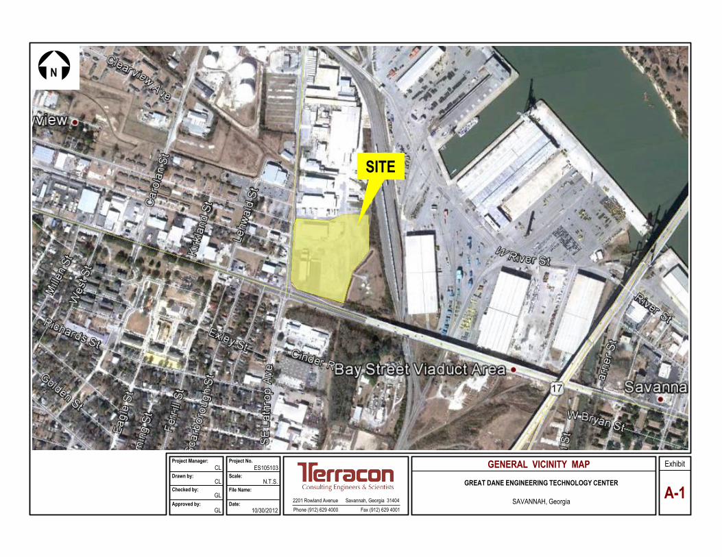
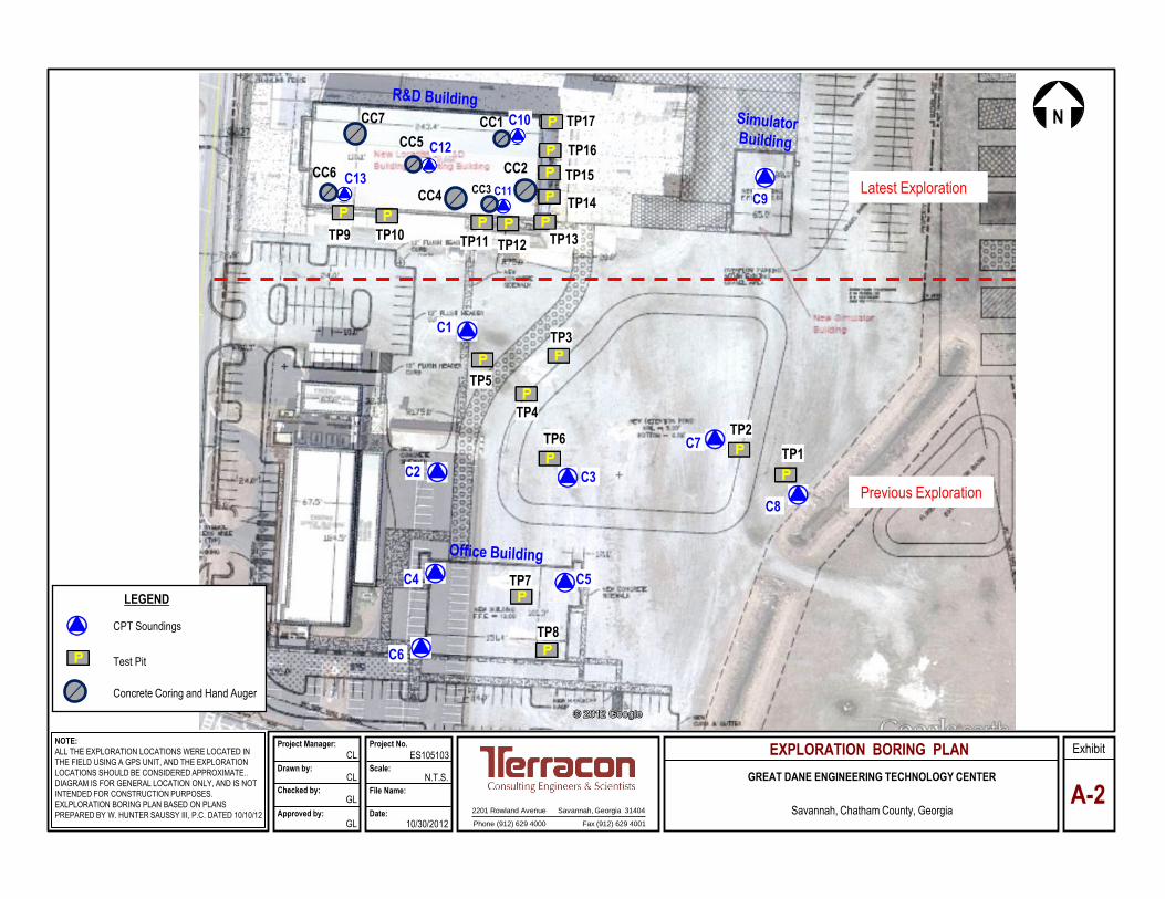
Exhibit A-1 Site Location Map Exhibit A-2 Exploration Location Diagram Exhibit A-3 CPT Sounding Cross Section Exhibit A-4 CPT Sounding Logs Exhibit A-5 Hand Auger Records Exhibit A-6 Measurement of Concrete Cores Exhibit A-7 Compressive Strength of Concrete Cores Exhibit A-8 Test Pit Records Exhibit A-9 Photos of Test Pit Excavation Exhibit A-10 Field Exploration Description
APPENDIX B: SUPPORTING INFORMATION
Exhibit B-1 Seismic Design Parameters Exhibit B-2 General Notes Exhibit B-3 Unified Soil Classification System
Geotechnical Engineering Investigation Great Dane Engineering Technology Center Savannah, Georgia November 14, 2012 Terracon Project No. ES105103
Responsive Resourceful Reliable i
EXECUTIVE SUMMARY A geotechnical investigation has been performed for the proposed Great Dane Engineering Technology Center in Savannah, Georgia. The field exploration consisted of field explorations carried out in several phases as presented in Appendix A. The initial exploration reported on October 24, 2011 included nine (9) cone penetration test (CPT) soundings and eight (8) test pits. The latest exploration consisted of five (5) CPT, seven (7) concrete corings and hand auger borings, and nine (9) test pits. The following geotechnical considerations were identified:
The project comprises three structures: a new Office Building, a R&D Building that will be constructed from renovation and expansion of the existing building and a new Simulator Building.
The subsurface soils are considered relatively poor and highly variable across
the site. In general, the site is underlain by soft to medium stiff sandy clay or medium dense clayey sand, with aggregates, debris, and concrete slab remnants to depths of 4 to 8 feet below ground surface (BGS). The underlying layers are interbedded medium dense sands and medium stiff to stiff sandy clay layers to the termination of soundings at depths of 42 to 44 feet BGS. The poor and non-uniform subsurface conditions were further complicated by the previous developments in different parts of the site.
For the Office Building, the updated design for the proposed Office Building
indicates both column and wall loads will be increased by 17% and 71%, respectively, from the previous design. Our settlement analyses indicated that the footings would experience settlement greater than one inch if no ground improvement is performed. A majority of the potential settlement will be from the weak soils in the upper 7 to 8 feet. We recommend stringent subgrade testing and undercut and backfill as the subgrade improvement measures to mitigate potential settlement. After subgrade improvement by undercut and backfill, the building can be supported shallow foundations designed with an allowable bearing capacity of 1500 pounds per square foot (psf). If more than three feet of fill is planned for the building, we recommend that fill be placed at least one month in advance of footing construction to allow the soft soils to consolidate under the weight of the fill. The thick fill would help bridge the weak soils which in turn would diminish the need for undercut. Alternatively, if the project schedule cannot accommodate one month of preloading, Rammed Aggregate Piers (Geopiers) may be used to improve the subsurface soil conditions to control potential settlement. After ground improvement by Geopiers, the proposed Office Building can be supported on the shallow foundations designed with an allowable bearing capacity of 4000 to 5000 psf.
Geotechnical Engineering Investigation Great Dane Engineering Technology Center Savannah, Georgia November 14, 2012 Terracon Project No. ES105103
Responsive Resourceful Reliable ii
We understand the R&D Building will be constructed over the existing footings and slab. The field investigation at the existing building shows the site may have undergone several previous developments, which left unusual foundation and slab configuration. Two layers of concrete slabs were observed during the concrete coring with the bottom slab 12 to 24 inches below the top one. Based on the soil profile and the loading conditions, we believe the existing slab and foundation can be reused for the support of the proposed R&D Building. The new foundation may be designed or evaluated based on allowable bearing capacity of 2000 psf and modulus of subgrade reaction of 100 pounds per cubic inch (pci).
We understand that the Simulator Building will include equipment that is
settlement sensitive. The existing Simulator Building is a conventionally steel framed structure with concrete tilt-wall at the perimeter and supported by timber piles. The new Simulator Building will consist of a relatively light pre-engineered metal structure. We recommend the new Simulator Building be supported on shallow foundations designed with an allowable bearing capacity of 2000 pounds per square foot. The simulator equipment should be supported on timber piles.
It is important to note the site history and subsurface conditions make it
imperative for Terracon to more thoroughly test the footing subgrade during construction. The contractor should be prepared to perform subgrade repair by undercut and backfill with #57 stone. The depth and extent of undercut should be determined during construction. The above foundation recommendations are predicated on the conditions that the footing subgrade will be tested and repaired as necessary. Terracon will provide additional guidance on subgrade testing and repair during construction.
In accordance with the 2006 International Building Code (IBC), Table 1613.5.2,
seismic site classification for this site is D.
This summary should be used in conjunction with the entire report for design purposes. It should be recognized that details were not included or fully developed in this section, and the report must be read in its entirety for a comprehensive understanding of the items and recommendations contained herein. The section titled GENERAL COMMENTS should be read for an understanding of the report’s limitations.
Responsive Resourceful Reliable 1
GEOTECHNICAL ENGINEERING INVESTIGATION GREAT DANE ENGINEERING TECHNOLOGY CENTER
Savannah, Georgia Terracon Project No. ES105103
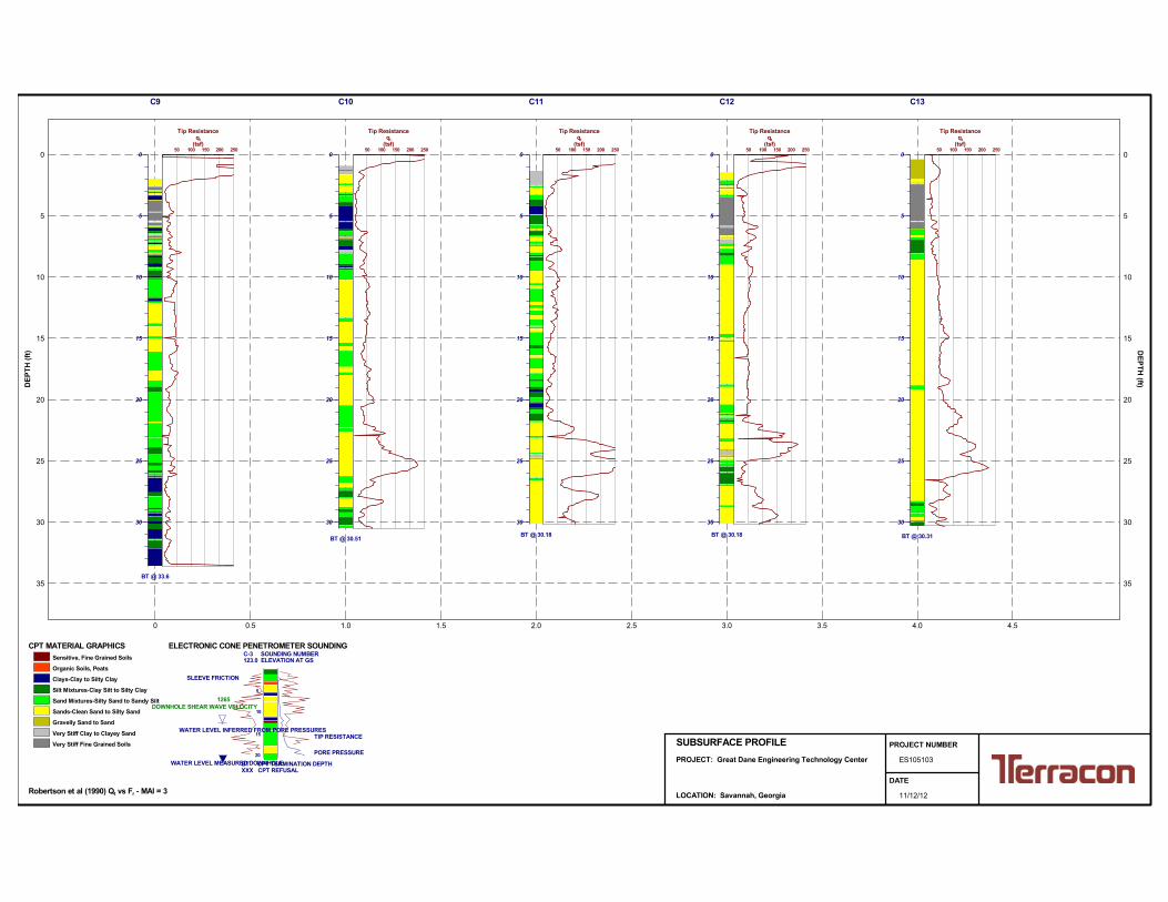
INTRODUCTION 1.0 A geotechnical engineering report has been completed for the proposed Great Dane Engineering Technology Center in Savannah, Georgia. The field exploration is made up of two phases of explorations which were conducted on October 24, 2011 and October 29, 2012, respectively, as presented in Appendix A-2. The initial phase field exploration program included eight (8) cone penetration test (CPT) soundings, designated C-1 through C-8 to a maximum depth of 40 feet below the existing ground surface (BGS). Eight (8) test pits, designated TP-1 through TP-8, were performed to a maximum depth of 7 feet BGS. However, most of the previous borings and tests were outside the footprint of the currently proposed buildings. A new field exploration program was conducted recently in October and November 10, 2012 due to the changes of building location and structural design. It consisted of five (5) CPT soundings (C9 through C13)) to an average depth of 30 feet BGS at the new simulator and R& D buildings, nine (9) test pits surrounding the existing building, and seven (7) concrete cores and hand auger borings inside the existing building. CPT sounding logs, test pits records, concrete coring logs and hand auger borings, along with a site vicinity map and exploration location diagram, are included in Appendix A of this report. The purpose of the study is to provide subsurface information and geotechnical engineering recommendations relative to:
subsurface soil conditions groundwater conditions foundation design and construction site preparation pavement recommendations seismic considerations
Geotechnical Engineering Investigation Great Dane Engineering Technology Center Savannah, Georgia November 14, 2012 Terracon Project No. ES105103
Responsive Resourceful Reliable 2
PROJECT INFORMATION 2.0 2.1 Project Description
ITEM DESCRIPTION
Structures
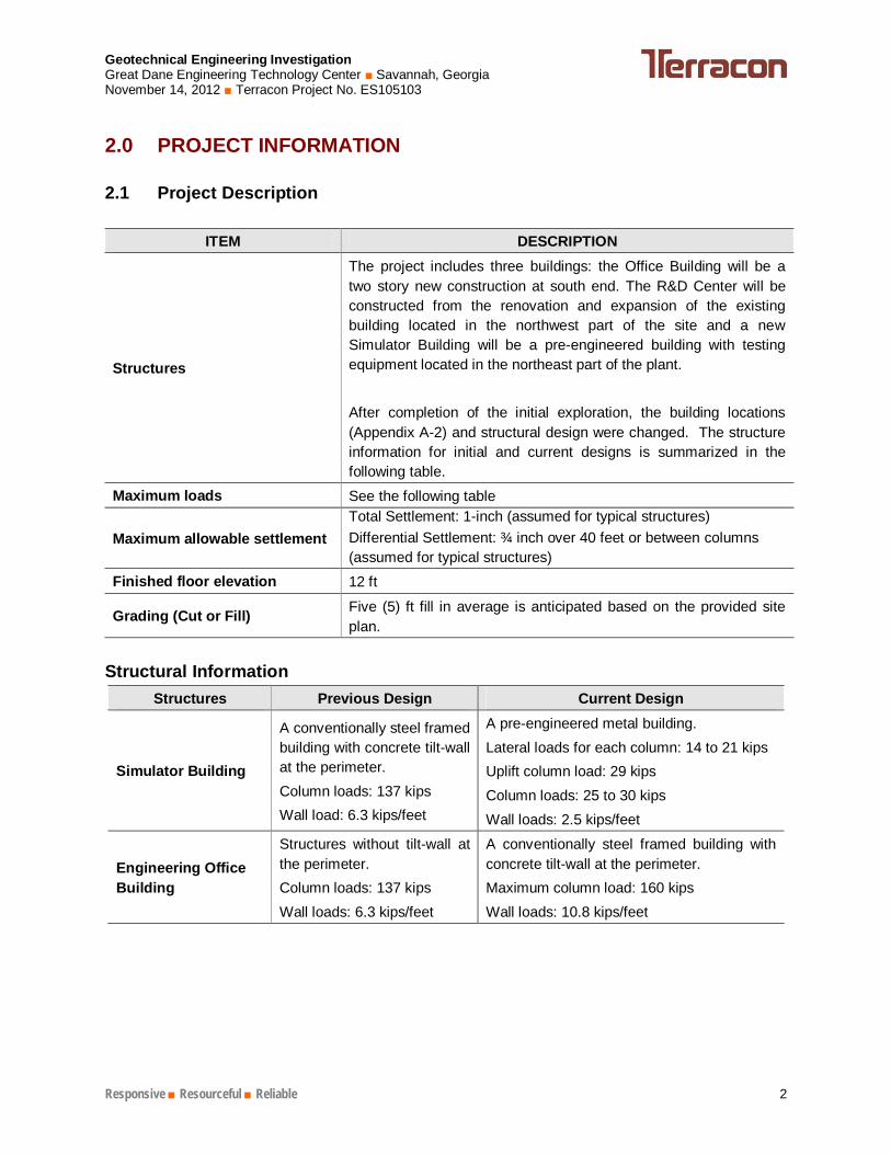
The project includes three buildings: the Office Building will be a two story new construction at south end. The R&D Center will be constructed from the renovation and expansion of the existing building located in the northwest part of the site and a new Simulator Building will be a pre-engineered building with testing equipment located in the northeast part of the plant. After completion of the initial exploration, the building locations (Appendix A-2) and structural design were changed. The structure information for initial and current designs is summarized in the following table.
Maximum loads See the following table
Maximum allowable settlement Total Settlement: 1-inch (assumed for typical structures) Differential Settlement: ¾ inch over 40 feet or between columns (assumed for typical structures)
Finished floor elevation 12 ft
Grading (Cut or Fill) Five (5) ft fill in average is anticipated based on the provided site plan.
Structural Information
Structures Previous Design Current Design
Simulator Building
A conventionally steel framed building with concrete tilt-wall at the perimeter. Column loads: 137 kips Wall load: 6.3 kips/feet
A pre-engineered metal building. Lateral loads for each column: 14 to 21 kips Uplift column load: 29 kips Column loads: 25 to 30 kips Wall loads: 2.5 kips/feet
Engineering Office Building
Structures without tilt-wall at the perimeter. Column loads: 137 kips Wall loads: 6.3 kips/feet
A conventionally steel framed building with concrete tilt-wall at the perimeter. Maximum column load: 160 kips Wall loads: 10.8 kips/feet
Geotechnical Engineering Investigation Great Dane Engineering Technology Center Savannah, Georgia November 14, 2012 Terracon Project No. ES105103
Responsive Resourceful Reliable 3
Structures Previous Design Current Design
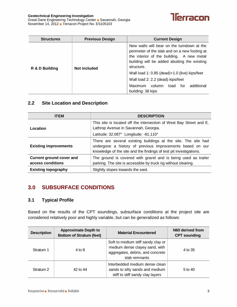
R & D Building Not included
New walls will bear on the turndown at the perimeter of the slab and on a new footing at the interior of the building. A new metal building will be added abutting the existing structure. Wall load 1: 0.85 (dead)+1.0 (live) kips/feet Wall load 2: 2.2 (dead) kips/feet Maximum column load for additional building: 38 kips
2.2 Site Location and Description
ITEM DESCRIPTION
Location This site is located off the intersection of West Bay Street and E. Lathrop Avenue in Savannah, Georgia. Latitude: 32.087° Longitude: -81.110°
Existing improvements There are several existing buildings at the site. The site had undergone a history of previous improvements based on our knowledge of the site and the findings of test pit investigations.
Current ground cover and access conditions
The ground is covered with gravel and is being used as trailer parking. The site is accessible by truck rig without clearing.
Existing topography Slightly slopes towards the east.
SUBSURFACE CONDITIONS 3.0 3.1 Typical Profile Based on the results of the CPT soundings, subsurface conditions at the project site are considered relatively poor and highly variable, but can be generalized as follows:
Description Approximate Depth to Bottom of Stratum (feet) Material Encountered N60 derived from
CPT sounding
Stratum 1 4 to 8
Soft to medium stiff sandy clay or medium dense clayey sand, with aggregates, debris, and concrete
slab remnants
4 to 35
Stratum 2 42 to 44 Interbedded medium dense clean sands to silty sands and medium
stiff to stiff sandy clay layers 5 to 40
Geotechnical Engineering Investigation Great Dane Engineering Technology Center Savannah, Georgia November 14, 2012 Terracon Project No. ES105103
Responsive Resourceful Reliable 4
Conditions encountered at each sounding location are indicated on the individual CPT sounding logs. Stratification boundaries on the logs represent the approximate depth of changes in soil types; the transition between materials may be gradual. Details for each of the soundings can be found on the CPT sounding logs in appendix A of this report. 3.2 Findings from Test Pits
Findings from Previous Test Pits 3.2.1The findings of the test pits included a mixture of soil and gravel at all test pit locations. A layer of concrete slab at a depth of approximately 1.5 feet BGS was noted in most of the test pit locations underneath the surface soil-gravel mixture (TP-2, TP-3, TP-4, TP-7 and TP-8). The slabs were relative thin and weak at the TP-2, TP-3 and TP-4 and the slabs can be broken using the excavator. However, the slab at the proposed Office Building was thick and sturdy (TP-7 and TP-8), which could not be broken using the excavator even after repeated attempts. As such, the thickness and horizontal extent of the old slab was not fully determined. Debris and organic matters were also noted in some parts of the site (TP-1, TP-4, TP-5 and TP-6). Clays were encountered below the slabs. The findings from test pits are in general consistent with the results of CPT soundings. All these findings will have significant implications to the construction and should be noted by the owner, engineers and the contractors. Photographs of typical test pit excavation are included in Appendix B of this report.
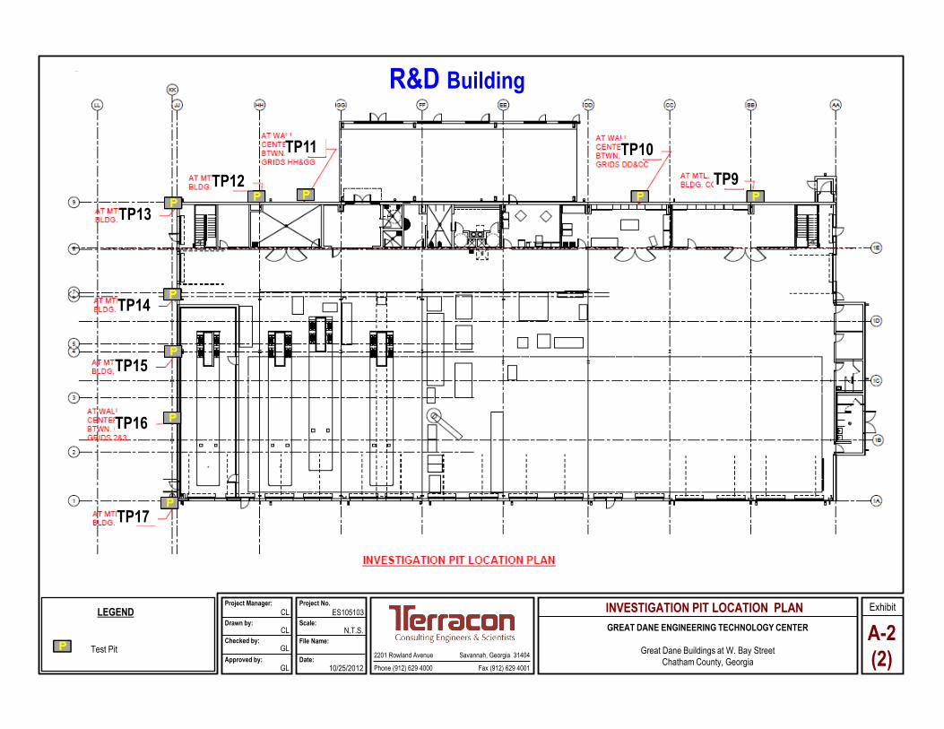
Findings from Recent Test Pits 3.2.2The new test pits (TP9 through TP17) were excavated along the exterior of the existing building to investigate the footing and soil conditions. Based on our observations, the subgrade materials under existing footing and slab were highly variable, consisting of sandy clays, clayey sands, silty sands, asphalt and gravels. The findings indicated that the footing and slab subgrade was not properly prepared during to the current standards and construction practices. The footing conditions will be discussed in greater detail in Section 4.2. 3.3 Groundwater No ground water was encountered during test pits excavation. However, the water table was encountered at depths of 8 to 11 feet BGS during the CPT soundings. It is important to note that groundwater levels tend to fluctuate with seasonal and climatic variations, as well as with construction activities. As such, the possibility of groundwater level fluctuations should be considered when developing the design and construction plans for the project. The groundwater table should be checked prior to construction to assess its effect on site work and other construction activities.
Geotechnical Engineering Investigation Great Dane Engineering Technology Center Savannah, Georgia November 14, 2012 Terracon Project No. ES105103
Responsive Resourceful Reliable 5
RECOMMENDATIONS FOR DESIGN AND CONSTRUCTION 4.0 4.1 Geotechnical Considerations Based on the findings of the CPT soundings and test pit excavations, the site subsurface conditions are relatively poor and highly variable. The previous developments further complicated the subsurface conditions and made them less uniform and unpredictable. In general, the site is underlain by soft to medium stiff sandy clay or medium dense clayey sand, with aggregates, debris, and concrete slab remnants to the depth of 4 to 8 ft BGS. The underlying layers are interbedded medium dense sands and medium stiff to stiff sandy clay layers to the termination of soundings at depths of 42 to 44 feet BGS. In addition to the soil conditions, we noticed that some of the buildings have been shifted in locations that outside the area of the previous experience. In light of the concrete debris and other unknowns associated with the previous development, additional exploration, while useful, would not be able to fully characterize the subsurface conditions. So in lieu of additional exploration, we strongly recommend more thorough subgrade testing during construction. The owner, designer and the contractor should be prepared to repair subgrade as needed. Terracon should perform additional testing at footing subgrade and recommend subgrade repairs to meet the design requirements. The following recommendations are predicated on this arrangement. Based on the provided load information (see Section 2.1), settlement analyses were performed at each CPT sounding location using the soil parameters derived from the CPT soundings. The considerations for foundation design for the proposed structures are presented as follows:
For the Office Building, our settlement analyses based on the current loads result in a total settlement of greater than one inch which is considered unacceptable to most structures. As a result, ground improvement will be necessary. Based on the three CPT soundings under the building footprint, the weak soils are typically in the upper 7 to 8 below existing. As such, undercut and backfill would be the most logical choice of subgrade repair under normal circumstances. However, if deep fill (more than three feet) will be required to raise the grade, it becomes difficult to undercut to a depth of up to 7 or 8 feet below the existing grades. We recommend the fill be placed at least one month prior to the footing excavation to allow the soft soils to consolidate under the weight of the fill. The need for undercut may be greatly diminished with the fill bridging over the weak soils. If the project schedule does not allow one month of preloading and depth of fill would make it infeasible to do undercut, rammed aggregate piers (Geopier) should be implemented in order to use shallow foundations to support the Office Building.
The Simulator Building contains equipment that will introduce dynamic loads and the structure is more settlement sensitive. We understand that the existing Simulator
Geotechnical Engineering Investigation Great Dane Engineering Technology Center Savannah, Georgia November 14, 2012 Terracon Project No. ES105103
Responsive Resourceful Reliable 6
Building is supported on timber piles and has performed well. Because the current design of Simulator Building results in a much lighter pre-engineered metal structure, we recommend the proposed Simulator Building be supported on shallow foundations. But the inside simulator foundation should be supported by timber piles. The uplift and lateral resistance for the building can be provided by extending the embedment and sizes of the footing.
We understand the R&D Building will be built over the existing footings and slab. The
field investigation shows the site may have undergone several previous developments which left unusual foundation and slab configurations. For example, two layers of concrete slabs were found with their thicknesses varying from 4.5 to 9 inches and the lower slab was 14 to 24 inches below the top one. Our settlement analyses shows the total settlement would be less than 1.0 inch under the current design loads. As such, the existing foundation and slab may be reused for support of the R&D Building. An allowable bearing capacity of 1500 psf is recommended for the foundation design. A modulus of subgrade reaction of 100 pci is recommended for slab evaluation and design.
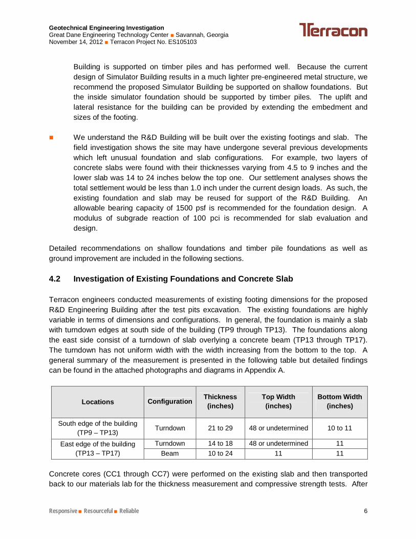
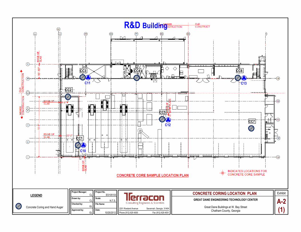
Detailed recommendations on shallow foundations and timber pile foundations as well as ground improvement are included in the following sections. 4.2 Investigation of Existing Foundations and Concrete Slab Terracon engineers conducted measurements of existing footing dimensions for the proposed R&D Engineering Building after the test pits excavation. The existing foundations are highly variable in terms of dimensions and configurations. In general, the foundation is mainly a slab with turndown edges at south side of the building (TP9 through TP13). The foundations along the east side consist of a turndown of slab overlying a concrete beam (TP13 through TP17). The turndown has not uniform width with the width increasing from the bottom to the top. A general summary of the measurement is presented in the following table but detailed findings can be found in the attached photographs and diagrams in Appendix A.
Locations Configuration Thickness (inches)
Top Width (inches)
Bottom Width (inches)
South edge of the building (TP9 – TP13)
Turndown 21 to 29 48 or undetermined 10 to 11
East edge of the building (TP13 – TP17)
Turndown 14 to 18 48 or undetermined 11 Beam 10 to 24 11 11
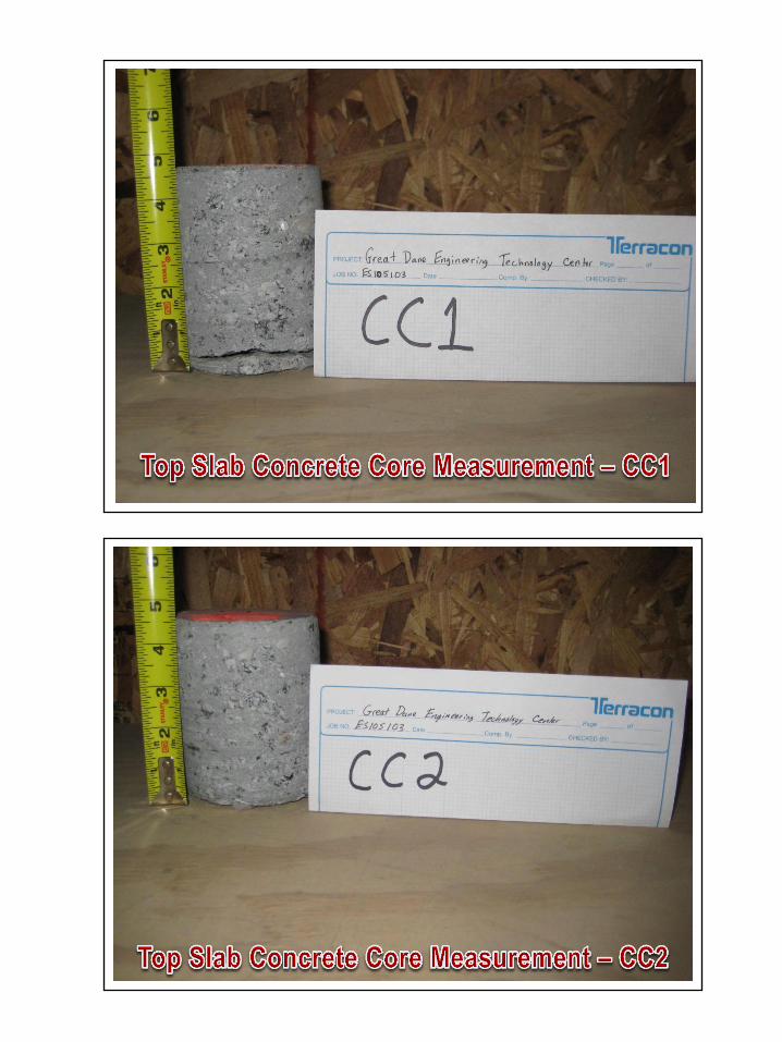
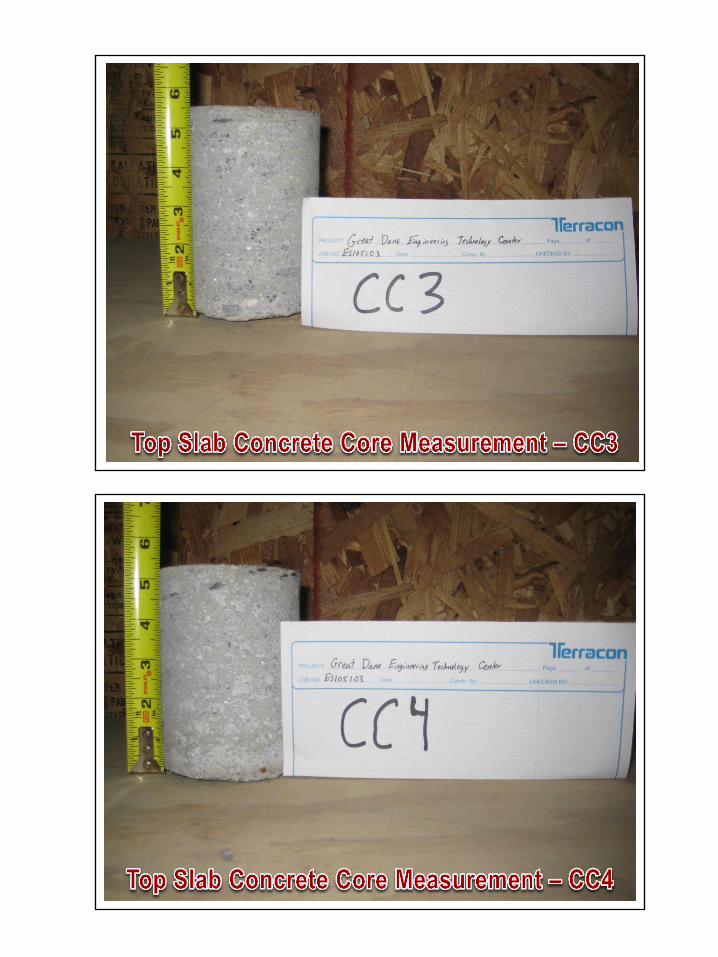
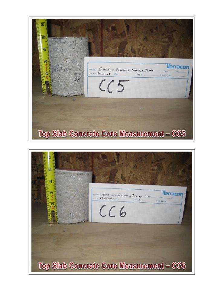
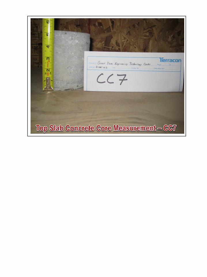
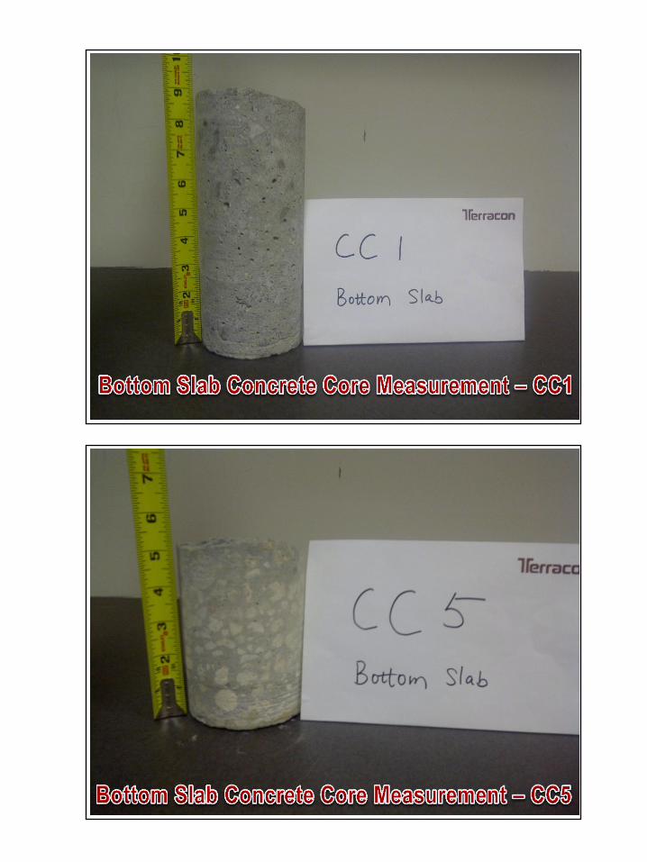
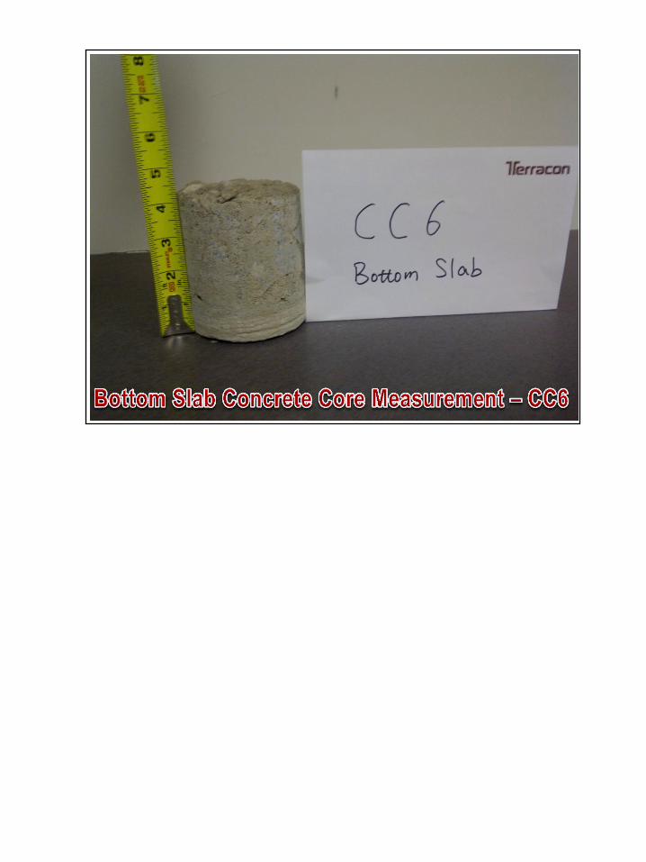
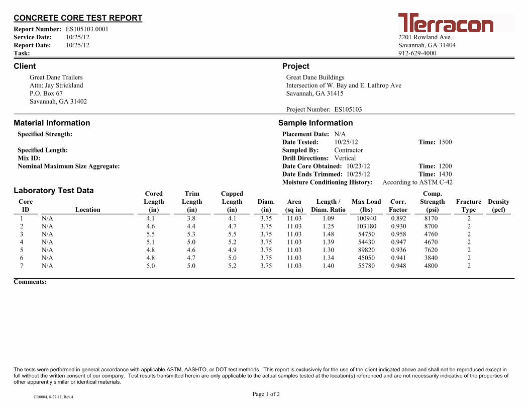
Concrete cores (CC1 through CC7) were performed on the existing slab and then transported back to our materials lab for the thickness measurement and compressive strength tests. After
Geotechnical Engineering Investigation Great Dane Engineering Technology Center Savannah, Georgia November 14, 2012 Terracon Project No. ES105103
Responsive Resourceful Reliable 7
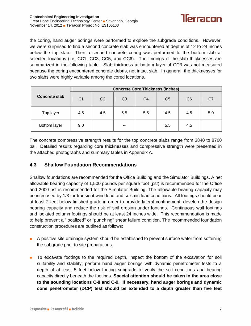
the coring, hand auger borings were performed to explore the subgrade conditions. However, we were surprised to find a second concrete slab was encountered at depths of 12 to 24 inches below the top slab. Then a second concrete coring was performed to the bottom slab at selected locations (i.e. CC1, CC3, CC5, and CC6). The findings of the slab thicknesses are summarized in the following table. Slab thickness at bottom layer of CC3 was not measured because the coring encountered concrete debris, not intact slab. In general, the thicknesses for two slabs were highly variable among the cored locations.
Concrete slab
Concrete Core Thickness (inches)
C1 C2 C3 C4 C5 C6 C7
Top layer 4.5 4.5 5.5 5.5 4.5 4.5 5.0
Bottom layer 9.0 -- 5.5 4.5
The concrete compressive strength results for the top concrete slabs range from 3840 to 8700 psi. Detailed results regarding core thicknesses and compressive strength were presented in the attached photographs and summary tables in Appendix A. 4.3 Shallow Foundation Recommendations Shallow foundations are recommended for the Office Building and the Simulator Buildings. A net allowable bearing capacity of 1,500 pounds per square foot (psf) is recommended for the Office and 2000 psf is recommended for the Simulator Building. The allowable bearing capacity may be increased by 1/3 for transient wind load and seismic load conditions. All footings should bear at least 2 feet below finished grade in order to provide lateral confinement, develop the design bearing capacity and reduce the risk of soil erosion under footings. Continuous wall footings and isolated column footings should be at least 24 inches wide. This recommendation is made to help prevent a "localized" or "punching" shear failure condition. The recommended foundation construction procedures are outlined as follows:
A positive site drainage system should be established to prevent surface water from softening the subgrade prior to site preparations.
To excavate footings to the required depth, inspect the bottom of the excavation for soil suitability and stability; perform hand auger borings with dynamic penetrometer tests to a depth of at least 5 feet below footing subgrade to verify the soil conditions and bearing capacity directly beneath the footings. Special attention should be taken in the area close to the sounding locations C-8 and C-9. If necessary, hand auger borings and dynamic cone penetrometer (DCP) test should be extended to a depth greater than five feet
Geotechnical Engineering Investigation Great Dane Engineering Technology Center Savannah, Georgia November 14, 2012 Terracon Project No. ES105103
Responsive Resourceful Reliable 8
below subgrade to better define the extent of the weak soils. The weak clayey soils should be removed and replaced with #57 stone.
Top soils and organic material should be removed prior to fill placement in the building and
pavement areas.
If unsuitable material such as organic soils or soft clays is encountered during footing inspection, they must be undercut and replaced with graded aggregates (#57 stone). If unstable material is encountered due to excessive moisture content, the excavated soils should be dried and re-compacted under favorable weather conditions or replaced with graded aggregates. The depth and extent of the undercut should be determined on-site by a Geotechnical Engineer based on the conditions of the weak material as well as footing size and design loads.
4.4 Rammed Aggregate Pier (Geopier) for the Office Building If the project schedule does not allow one month of preloading of fill and the fill will make is too difficult to perform undercut, Rammed Aggregate Piers (Geopiers) may be used under the foundations of the Office Building to stiffen the soils in the near surface layers to reduce settlements. After ground improvement using aggregate piers, the proposed structures can be supported on shallow foundation systems, resting on improved soils designed with a net allowable bearing pressure of 4000 to 5000 pounds per square foot (psf). The piers should be designed and installed to limit the maximum settlement to 1.0 inches and differential settlements between columns to 0.5 inches. Aggregate piers are a proprietary technology and the contractor should be solely responsible to the design, installation and performance of the ground improvement system. If aggregate piers are selected, the following recommendations should be considered prior to construction.
The specialty contractor should design the piers with proper depth; spacing and other details based on the soil conditions and project requirements and prepare specifications for installation. The design and specification should be submitted to the structural engineer and geotechnical engineer for review and approval;
At least one demonstration pier should be installed using the Contractor’s proposed procedures and then load-tested to determine the composite modulus of the improved ground. The specialty contractor should prepare plan to show the load testing setup and procedures and submit the plan for review by the structural engineer and geotechnical engineer. The demonstration pier should be installed at the foundation grade level. The geotechnical engineer should observe the installation and participate in the testing program.
Geotechnical Engineering Investigation Great Dane Engineering Technology Center Savannah, Georgia November 14, 2012 Terracon Project No. ES105103
Responsive Resourceful Reliable 9
An engineer working for the specialty contractor should perform calculations to verify the
design assumptions including soil modulus through the test program. Additional piers should be installed and tested if the test pier fails to meet the design requirements.
All production piers should be installed based on the procedures established after the
demonstration pier. Terracon should be retained to monitor the installation of all production piers.
4.5 Timber Pile Recommendations The Simulator should be supported on foundations on driven timber piles. The timber piles should have a minimum tip diameter of 8 inches. All piles should penetrate through the variable soil layers to have a minimum depth of 24 feet below the existing grades. All piles should be 45 feet in length and be driven in to the very dense or hard layer until penetration refusal is encountered. An allowable capacity of 20 tons in compression and 12 tons in tension are recommended for the design. A lateral capacity of 1 kip is recommended for free head condition and 2 kips for fixed or restrained pile head conditions. The existence of the near surface concrete debris may cause driving difficulties of timber pile. Predrilling or limited excavation may be required to the timber to penetrate through the upper crest. Terracon should observe the pile installation to confirm the driving conditions are consistent with soil conditions and make additional recommendations as necessary. The timber piles may be cut off the pile encounters penetration refusal after the pile capacity is verified by the geotechnical engineer. 4.6 Slab on Grade Recommendations The slab may be designed using a modulus of subgrade reaction (Ks) of 100 pci. The concrete slab should be designed in accordance with the requirements for construction joints, expansion joints and saw cuts as recommended by the American Concrete Institute (ACI). The slab should have a minimum thickness of 6 inches and be separated from columns and footings to allow relative movements. The slab subgrade should be compacted to 95% of its Modified Proctor maximum dry density (ASTM D-1557 or AASHTO T-180). 4.7 Site Preparation Recommendations Due to the presence of old concrete and debris and planned fill, we recommend an unconventional site preparation procedures. Instead of placing fill after stripping and grubbing, we recommend the contractor to stake out the foundation locations and start to test excavation. The test excavation should be conducted under the observation of Terracon engineer to expose all buried foundations and debris that would potentially interfere with new foundation construction. The old foundations and debris should be removed and disturbed subgrade
Geotechnical Engineering Investigation Great Dane Engineering Technology Center Savannah, Georgia November 14, 2012 Terracon Project No. ES105103
Responsive Resourceful Reliable 10
should be repaired. The contractor can continue with fill placement after subgrade repair. The procedure will avoid digging below the fill.
Site Drainage 4.7.1A positive drainage system should be installed prior to site preparation and grading activities to intercept surface water and to improve shallow drainage. The drainage system may consist of perimeter ditches aided with parallel ditches and swales. Pumping equipment should be prepared if the above ditch system cannot effectively drain water away from the site especially during the rainy season. The site should be graded to shed water and avoid ponding over subgrade. Failure to establish positive site drainage will result in construction delays, additional undercutting and backfilling and costs to the contractor and the owner.
Densification and Proofrolling 4.7.2After removal of debris and prior to fill placement, the entire building and pavement subgrade should be densified with a heavy-duty roller to achieve a uniform subgrade. The subgrade should be thoroughly proofrolled after the completion of densification. Proofrolling will help detect any isolated soft or loose areas that "pump", deflect or rut excessively, and also densify the near surface soils for floor slab support. A fully loaded pneumatic tired tandem axle dump truck, capable of transferring a load of in excess of 20 tons, should be utilized for this operation. Proofrolling should be performed under the geotechnical engineer’s observation. During proofrolling, areas where pumping, excessive deflection or rutting is observed after successive passes of the proofrolling equipment, should be undercut, backfilled and properly compacted.
Fill Material Consideration 4.7.3Structural fill should be placed over a stable or stabilized subgrade. The soils to be used as structural fill should be free of organics, roots, or other deleterious materials. It should be non-plastic granular material containing less than 25 percent fines passing the No. 200 sieve. All structural fills should be placed in thin (6 to 8 inches loose) lifts and compacted to a minimum of 95% of the soil's modified proctor maximum dry density (ASTM D-1557). Fill brought to the site should be within three percent (wet or dry) of the optimum moisture content. Some manipulation of the moisture content (such as wetting, drying) will be required during the filling operation to obtain the required degree of compaction. The manipulation of the moisture content is highly dependent on weather conditions and site drainage conditions. Therefore, the contractor should prepare both dry and wet fill materials to obtain the specified compaction during grading. Sufficient density tests should be performed to confirm the required compaction of the fill material. 4.8 Pavement Recommendations
Geotechnical Engineering Investigation Great Dane Engineering Technology Center Savannah, Georgia November 14, 2012 Terracon Project No. ES105103
Responsive Resourceful Reliable 11
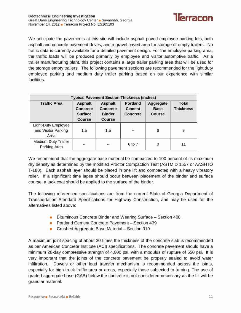
We anticipate the pavements at this site will include asphalt paved employee parking lots, both asphalt and concrete pavement drives, and a gravel paved area for storage of empty trailers. No traffic data is currently available for a detailed pavement design. For the employee parking area, the traffic loads will be produced primarily by employee and visitor automotive traffic. As a trailer manufacturing plant, this project contains a large trailer parking area that will be used for the storage empty trailers. The following pavement sections are recommended for the light duty employee parking and medium duty trailer parking based on our experience with similar facilities.
Typical Pavement Section Thickness (inches) Traffic Area Asphalt
Concrete Surface Course
Asphalt Concrete
Binder Course
Portland Cement
Concrete
Aggregate Base
Course
Total Thickness
Light-Duty Employee and Visitor Parking
Area 1.5 1.5 -- 6 9
Medium Duty Trailer Parking Area
-- -- 6 to 7 0 11
We recommend that the aggregate base material be compacted to 100 percent of its maximum dry density as determined by the modified Proctor Compaction Test (ASTM D 1557 or AASHTO T-180). Each asphalt layer should be placed in one lift and compacted with a heavy vibratory roller. If a significant time lapse should occur between placement of the binder and surface course, a tack coat should be applied to the surface of the binder. The following referenced specifications are from the current State of Georgia Department of Transportation Standard Specifications for Highway Construction, and may be used for the alternatives listed above:
Bituminous Concrete Binder and Wearing Surface – Section 400 Portland Cement Concrete Pavement – Section 439 Crushed Aggregate Base Material – Section 310
A maximum joint spacing of about 30 times the thickness of the concrete slab is recommended as per American Concrete Institute (ACI) specifications. The concrete pavement should have a minimum 28-day compressive strength of 4,000 psi, with a modulus of rupture of 550 psi. It is very important that the joints of the concrete pavement be properly sealed to avoid water infiltration. Dowels or other load transfer mechanism is recommended across the joints, especially for high truck traffic area or areas, especially those subjected to turning. The use of graded aggregate base (GAB) below the concrete is not considered necessary as the fill will be granular material.
Geotechnical Engineering Investigation Great Dane Engineering Technology Center Savannah, Georgia November 14, 2012 Terracon Project No. ES105103
Responsive Resourceful Reliable 12
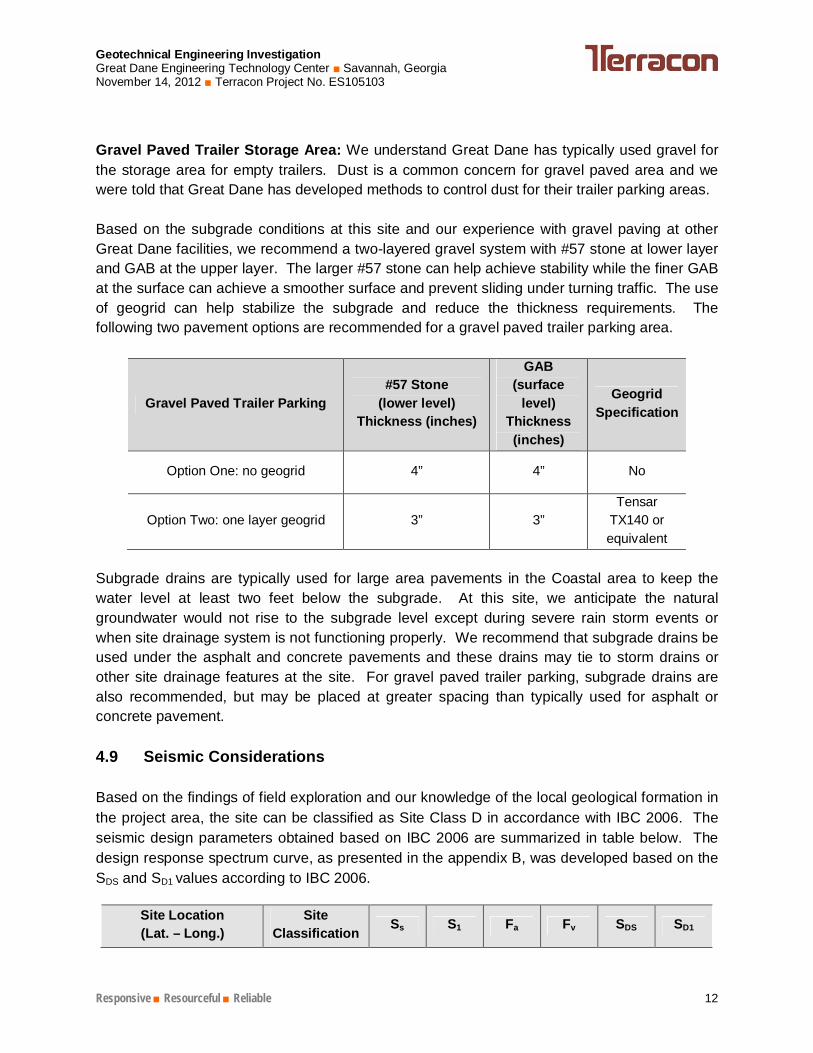
Gravel Paved Trailer Storage Area: We understand Great Dane has typically used gravel for the storage area for empty trailers. Dust is a common concern for gravel paved area and we were told that Great Dane has developed methods to control dust for their trailer parking areas. Based on the subgrade conditions at this site and our experience with gravel paving at other Great Dane facilities, we recommend a two-layered gravel system with #57 stone at lower layer and GAB at the upper layer. The larger #57 stone can help achieve stability while the finer GAB at the surface can achieve a smoother surface and prevent sliding under turning traffic. The use of geogrid can help stabilize the subgrade and reduce the thickness requirements. The following two pavement options are recommended for a gravel paved trailer parking area.
Gravel Paved Trailer Parking #57 Stone
(lower level) Thickness (inches)
GAB (surface
level) Thickness (inches)
Geogrid Specification
Option One: no geogrid 4” 4” No
Option Two: one layer geogrid 3” 3” Tensar
TX140 or equivalent
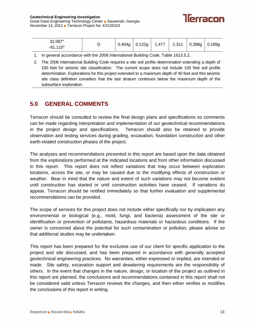
Subgrade drains are typically used for large area pavements in the Coastal area to keep the water level at least two feet below the subgrade. At this site, we anticipate the natural groundwater would not rise to the subgrade level except during severe rain storm events or when site drainage system is not functioning properly. We recommend that subgrade drains be used under the asphalt and concrete pavements and these drains may tie to storm drains or other site drainage features at the site. For gravel paved trailer parking, subgrade drains are also recommended, but may be placed at greater spacing than typically used for asphalt or concrete pavement. 4.9 Seismic Considerations Based on the findings of field exploration and our knowledge of the local geological formation in the project area, the site can be classified as Site Class D in accordance with IBC 2006. The seismic design parameters obtained based on IBC 2006 are summarized in table below. The design response spectrum curve, as presented in the appendix B, was developed based on the SDS and SD1 values according to IBC 2006.
Site Location (Lat. – Long.)
Site Classification Ss S1 Fa Fv SDS SD1
Geotechnical Engineering Investigation Great Dane Engineering Technology Center Savannah, Georgia November 14, 2012 Terracon Project No. ES105103
Responsive Resourceful Reliable 13
32.087° -81.110°
D 0.404g 0.122g 1.477 2.311 0.398g 0.189g
1. In general accordance with the 2006 International Building Code, Table 1613.5.2. 2. The 2006 International Building Code requires a site soil profile determination extending a depth of
100 feet for seismic site classification. The current scope does not include 100 feet soil profile determination. Explorations for this project extended to a maximum depth of 40 feet and this seismic site class definition considers that the last stratum continues below the maximum depth of the subsurface exploration.
GENERAL COMMENTS 5.0 Terracon should be consulted to review the final design plans and specifications so comments can be made regarding interpretation and implementation of our geotechnical recommendations in the project design and specifications. Terracon should also be retained to provide observation and testing services during grading, excavation, foundation construction and other earth-related construction phases of the project. The analyses and recommendations presented in this report are based upon the data obtained from the explorations performed at the indicated locations and from other information discussed in this report. This report does not reflect variations that may occur between exploration locations, across the site, or may be caused due to the modifying effects of construction or weather. Bear in mind that the nature and extent of such variations may not become evident until construction has started or until construction activities have ceased. If variations do appear, Terracon should be notified immediately so that further evaluation and supplemental recommendations can be provided. The scope of services for this project does not include either specifically nor by implication any environmental or biological (e.g., mold, fungi, and bacteria) assessment of the site or identification or prevention of pollutants, hazardous materials or hazardous conditions. If the owner is concerned about the potential for such contamination or pollution, please advise so that additional studies may be undertaken. This report has been prepared for the exclusive use of our client for specific application to the project and site discussed, and has been prepared in accordance with generally accepted geotechnical engineering practices. No warranties, either expressed or implied, are intended or made. Site safety, excavation support and dewatering requirements are the responsibility of others. In the event that changes in the nature, design, or location of the project as outlined in this report are planned, the conclusions and recommendations contained in this report shall not be considered valid unless Terracon reviews the changes, and then either verifies or modifies the conclusions of this report in writing.
APPENDIX A
FIELD EXPLORATION
Exhibit A-1 Site Location Map Exhibit A-2 Exploration Location Plan Exhibit A-3 CPT Sounding Cross Section Exhibit A-4 CPT Sounding Logs Exhibit A-5 Hand Auger Logs Exhibit A-6 Measurement of Concrete Cores Exhibit A-7 Compressive Strength of Concrete Cores Exhibit A-8 Test Pit Records Exhibit A-9 Photos of Test Pit Excavation Exhibit A-10 Field Exploration Description
A-1
Exhibit GENERAL VICINITY MAP
GREAT DANE ENGINEERING TECHNOLOGY CENTER
SAVANNAH, Georgia 2201 Rowland Avenue Savannah, Georgia 31404
Phone (912) 629 4000 Fax (912) 629 4001
SITE
N
ES105103
10/30/2012
CL
CL
GL
GL
N.T.S.
Project Manager:
Drawn by:
Checked by:
Approved by:
Project No.
Scale:
File Name:
Date:
ES105103
10/30/2012
CL
CL
GL
GL
N.T.S.
Project Manager:
Drawn by:
Checked by:
Approved by:
Project No.
Scale:
File Name:
Date:
NOTE:
ALL THE EXPLORATION LOCATIONS WERE LOCATED IN
THE FIELD USING A GPS UNIT, AND THE EXPLORATION
LOCATIONS SHOULD BE CONSIDERED APPROXIMATE..
DIAGRAM IS FOR GENERAL LOCATION ONLY, AND IS NOT
INTENDED FOR CONSTRUCTION PURPOSES.
EXLPLORATION BORING PLAN BASED ON PLANS
PREPARED BY W. HUNTER SAUSSY III, P.C. DATED 10/10/12
2201 Rowland Avenue Savannah, Georgia 31404
Phone (912) 629 4000 Fax (912) 629 4001
N
A-2
Exhibit EXPLORATION BORING PLAN
GREAT DANE ENGINEERING TECHNOLOGY CENTER
Savannah, Chatham County, Georgia
C1
C2 C3
C4 C5
C6
C7
C8
C9
TP1
TP2
TP3
TP4
TP5
TP6
TP7
TP8
TP9 TP10 TP11 TP12 TP13
TP14
TP15
TP16
TP17 CC1
CC2
CC3 CC4
CC5
CC6
CC7
LEGEND
CPT Soundings
Test Pit
Concrete Coring and Hand Auger
Latest Exploration
Previous Exploration
C10
C11
C12
C13
2201 Rowland Avenue Savannah, Georgia 31404
Phone (912) 629 4000 Fax (912) 629 4001
ES105103
10/25/2012
CL
CL
GL
GL
N.T.S.
Project Manager:
Drawn by:
Checked by:
Approved by:
Project No.
Scale:
File Name:
Date:
Exhibit
A-2
(1)
CONCRETE CORING LOCATION PLAN
GREAT DANE ENGINEERING TECHNOLOGY CENTER
Great Dane Buildings at W. Bay Street
Chatham County, Georgia
CC1
CC2
CC3 CC4 CC6
CC5
CC7
LEGEND
Concrete Coring and Hand Auger
C11
C10
C12
C13
R&D Building
2201 Rowland Avenue Savannah, Georgia 31404
Phone (912) 629 4000 Fax (912) 629 4001
ES105103
10/25/2012
CL
CL
GL
GL
N.T.S.
Project Manager:
Drawn by:
Checked by:
Approved by:
Project No.
Scale:
File Name:
Date:
Exhibit
C2
N
A-2
(2)
INVESTIGATION PIT LOCATION PLAN
GREAT DANE ENGINEERING TECHNOLOGY CENTER
Great Dane Buildings at W. Bay Street
Chatham County, Georgia
LEGEND
Test Pit
TP9
TP10 TP11
TP12
TP13
TP14
TP15
TP16
TP17
R&D Building
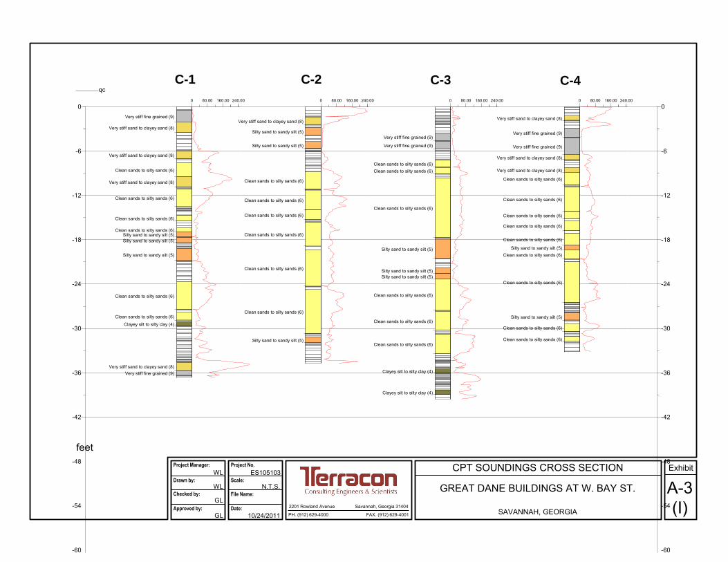
CPT SOUNDINGS CROSS SECTION
GREAT DANE BUILDINGS AT W. BAY ST.
SAVANNAH, GEORGIA
A-3(I)2201 Rowland Avenue Savannah, Georgia 31404
PH. (912) 629-4000 FAX. (912) 629-4001
ES105103
10/24/2011
WL
WL
GL
GL
N.T.S.
Project Manager:
Drawn by:
Checked by:
Approved by:
Project No.
Scale:
File Name:
Date:
Exhibit
feet
C-1 C-2 C-3 C-4
-60
-54
-48
-42
-36
-30
-24
-18
-12
-6
0
-60
-54
-48
-42
-36
-30
-24
-18
-12
-6
0
C1
0.00 feet
30.00 feet
C2
10.00 feet
20.00 feet
C3
20.00 feet
10.00 feet
C4
30.00 feet
0.00 feet
Very stiff fine grained (9)
Very stiff sand to clayey sand (8)
Very stiff sand to clayey sand (8)
Clean sands to silty sands (6)
Very stiff sand to clayey sand (8)
Clean sands to silty sands (6)
Clean sands to silty sands (6)
Clean sands to silty sands (6)Silty sand to sandy silt (5)Silty sand to sandy silt (5)
Silty sand to sandy silt (5)
Clean sands to silty sands (6)
Clean sands to silty sands (6)
Clayey silt to silty clay (4)
Very stiff sand to clayey sand (8)Very stiff fine grained (9)
Very stiff sand to clayey sand (8)
Silty sand to sandy silt (5)
Silty sand to sandy silt (5)
Clean sands to silty sands (6)
Clean sands to silty sands (6)
Clean sands to silty sands (6)
Clean sands to silty sands (6)
Clean sands to silty sands (6)
Clean sands to silty sands (6)
Silty sand to sandy silt (5)
Very stiff fine grained (9)
Very stiff fine grained (9)
Clean sands to silty sands (6)Clean sands to silty sands (6)
Clean sands to silty sands (6)
Silty sand to sandy silt (5)
Silty sand to sandy silt (5)Silty sand to sandy silt (5)
Clean sands to silty sands (6)
Clean sands to silty sands (6)
Clean sands to silty sands (6)
Clayey silt to silty clay (4)
Clayey silt to silty clay (4)
Very stiff sand to clayey sand (8)
Very stiff fine grained (9)
Very stiff fine grained (9)
Very stiff sand to clayey sand (8)
Very stiff sand to clayey sand (8)
Clean sands to silty sands (6)
Clean sands to silty sands (6)
Clean sands to silty sands (6)
Clean sands to silty sands (6)
Clean sands to silty sands (6)
Silty sand to sandy silt (5)Clean sands to silty sands (6)
Clean sands to silty sands (6)
Silty sand to sandy silt (5)
Clean sands to silty sands (6)
Clean sands to silty sands (6)
[ feet]
0 80.00 160.00 240.00 0 80.00 160.00 240.00 0 80.00 160.00 240.00 0 80.00 160.00 240.00
qc
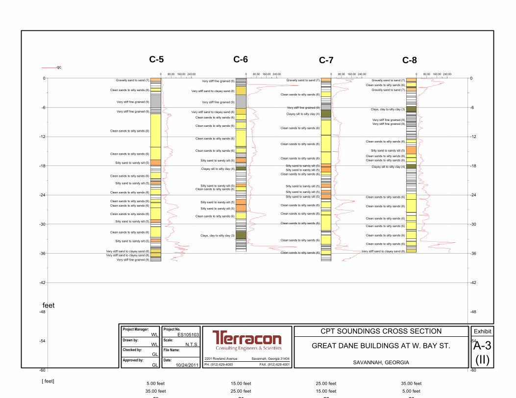
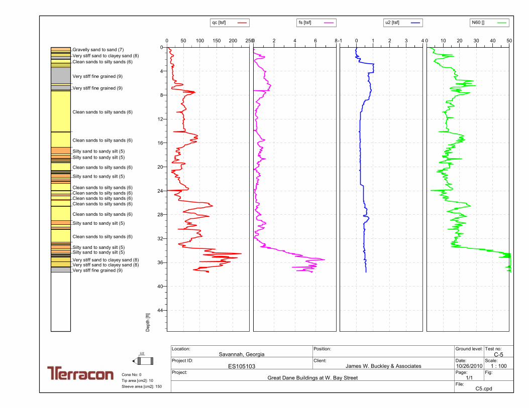
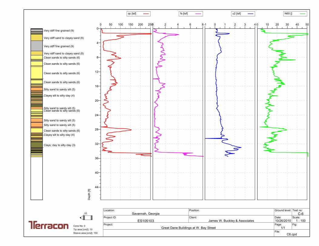
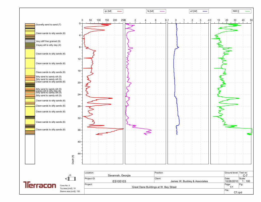
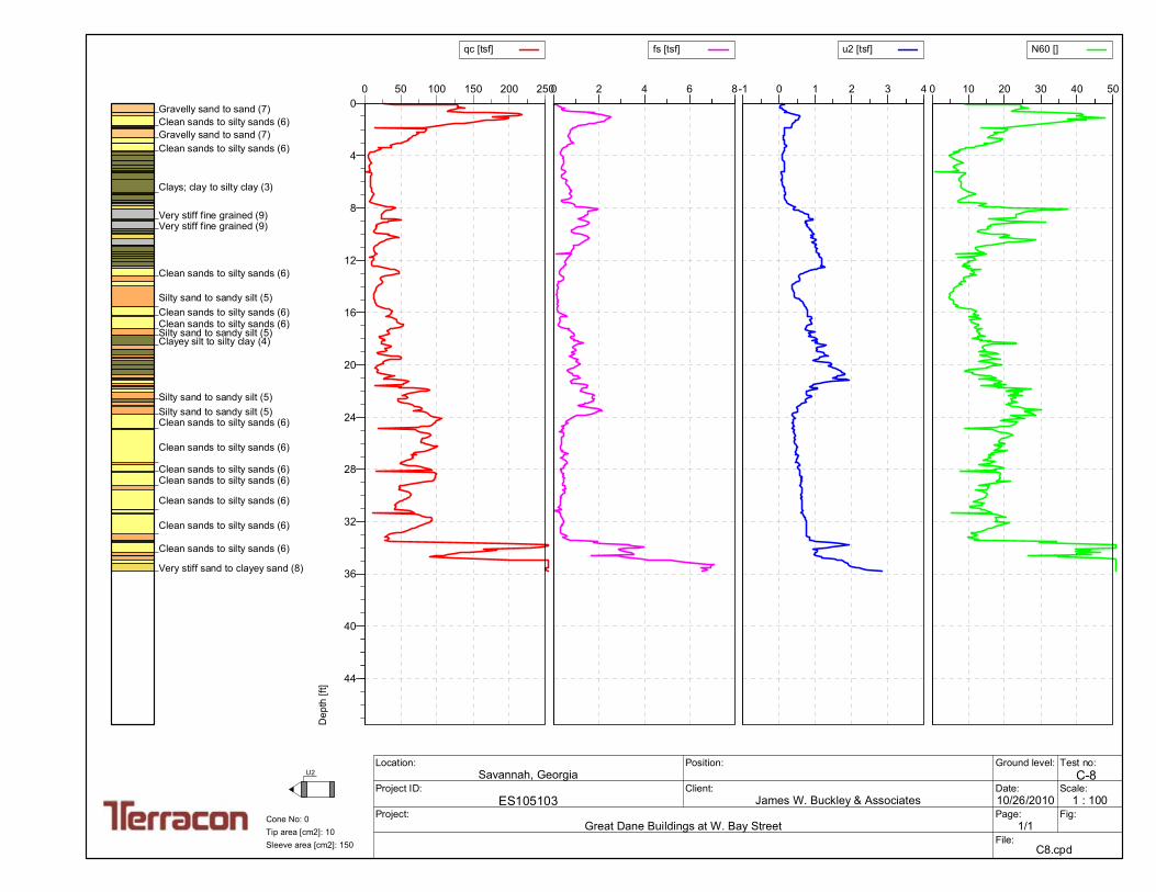
CPT SOUNDINGS CROSS SECTION
GREAT DANE BUILDINGS AT W. BAY ST.
SAVANNAH, GEORGIA
A-3(II)2201 Rowland Avenue Savannah, Georgia 31404
PH. (912) 629-4000 FAX. (912) 629-4001
ES105103
10/24/2011
WL
WL
GL
GL
N.T.S.
Project Manager:
Drawn by:
Checked by:
Approved by:
Project No.
Scale:
File Name:
Date:
Exhibit
feet
C-5 C-6 C-7 C-8
-60
-54
-48
-42
-36
-30
-24
-18
-12
-6
0
-60
-54
-48
-42
-36
-30
-24
-18
-12
-6
0
C5
5.00 feet
35.00 feet
C6
15.00 feet
25.00 feet
C7
25.00 feet
15.00 feet
C8
35.00 feet
5.00 feet
Gravelly sand to sand (7)
Clean sands to silty sands (6)
Very stiff fine grained (9)
Very stiff fine grained (9)
Clean sands to silty sands (6)
Clean sands to silty sands (6)
Silty sand to sandy silt (5)
Clean sands to silty sands (6)
Silty sand to sandy silt (5)
Clean sands to silty sands (6)
Clean sands to silty sands (6)Clean sands to silty sands (6)
Clean sands to silty sands (6)
Silty sand to sandy silt (5)
Clean sands to silty sands (6)
Silty sand to sandy silt (5)
Very stiff sand to clayey sand (8)Very stiff sand to clayey sand (8)
Very stiff fine grained (9)
Very stiff fine grained (9)
Very stiff sand to clayey sand (8)
Very stiff fine grained (9)
Very stiff sand to clayey sand (8)
Clean sands to silty sands (6)
Clean sands to silty sands (6)
Clean sands to silty sands (6)
Clean sands to silty sands (6)
Silty sand to sandy silt (5)
Clayey silt to silty clay (4)
Silty sand to sandy silt (5)Clean sands to silty sands (6)
Silty sand to sandy silt (5)
Silty sand to sandy silt (5)
Clean sands to silty sands (6)
Clays, clay to silty clay (3)
Gravelly sand to sand (7)
Clean sands to silty sands (6)
Very stiff fine grained (9)
Clayey silt to silty clay (4)
Clean sands to silty sands (6)
Clean sands to silty sands (6)
Clean sands to silty sands (6)
Silty sand to sandy silt (5)Silty sand to sandy silt (5)
Clean sands to silty sands (6)
Silty sand to sandy silt (5)
Silty sand to sandy silt (5)Silty sand to sandy silt (5)
Clean sands to silty sands (6)
Clean sands to silty sands (6)
Clean sands to silty sands (6)
Clean sands to silty sands (6)
Clean sands to silty sands (6)
Gravelly sand to sand (7)Clean sands to silty sands (6)
Gravelly sand to sand (7)
Clays, clay to silty clay (3)
Very stiff fine grained (9)Very stiff fine grained (9)
Clean sands to silty sands (6)
Silty sand to sandy silt (5)
Clean sands to silty sands (6)Clean sands to silty sands (6)
Clayey silt to silty clay (4)
Clean sands to silty sands (6)
Clean sands to silty sands (6)
Clean sands to silty sands (6)
Clean sands to silty sands (6)
Clean sands to silty sands (6)
Clean sands to silty sands (6)
Very stiff sand to clayey sand (8)
[ feet]
0 80.00 160.00 240.00 0 80.00 160.00 240.00 0 80.00 160.00 240.00 0 80.00 160.00 240.00
qc
0
5
10
15
20
25
30
35
0 0.5 1.0 1.5 2.0 2.5 3.0 3.5 4.0 4.5
0
5
10
15
20
25
30
35
C10
BT @ 30.51
0
5
10
15
20
25
30
50 100 150 200 250
Tip Resistanceqt
(tsf)
C11
BT @ 30.18
0
5
10
15
20
25
30
50 100 150 200 250
Tip Resistanceqt
(tsf)
C12
BT @ 30.18
0
5
10
15
20
25
30
50 100 150 200 250
Tip Resistanceqt
(tsf)
C13
BT @ 30.31
0
5
10
15
20
25
30
50 100 150 200 250
Tip Resistanceqt
(tsf)
C9
BT @ 33.6
0
5
10
15
20
25
30
50 100 150 200 250
Tip Resistanceqt
(tsf)
DE
PT
H (ft)D
EP
TH
(ft
)
20
10
15
5
1265
C-3 SOUNDING NUMBER123.0 ELEVATION AT GS
WATER LEVEL MEASURED DOWNHOLE
TIP RESISTANCE
PORE PRESSURE
WATER LEVEL INFERRED FROM PORE PRESSURES
DOWNHOLE SHEAR WAVE VELOCITY
SLEEVE FRICTION
BT CPT TERMINATION DEPTHXXX CPT REFUSAL
ELECTRONIC CONE PENETROMETER SOUNDING
SUBSURFACE PROFILE
PROJECT: Great Dane Engineering Technology Center
LOCATION: Savannah, Georgia
ES105103
11/12/12
PROJECT NUMBER
DATE
Robertson et al (1990) Qt vs Fr - MAI = 3
CPT MATERIAL GRAPHICS
Sensitive, Fine Grained Soils
Organic Soils, Peats
Clays-Clay to Silty Clay
Silt Mixtures-Clay Silt to Silty Clay
Sand Mixtures-Silty Sand to Sandy Silt
Sands-Clean Sand to Silty Sand
Gravelly Sand to Sand
Very Stiff Clay to Clayey Sand
Very Stiff Fine Grained Soils
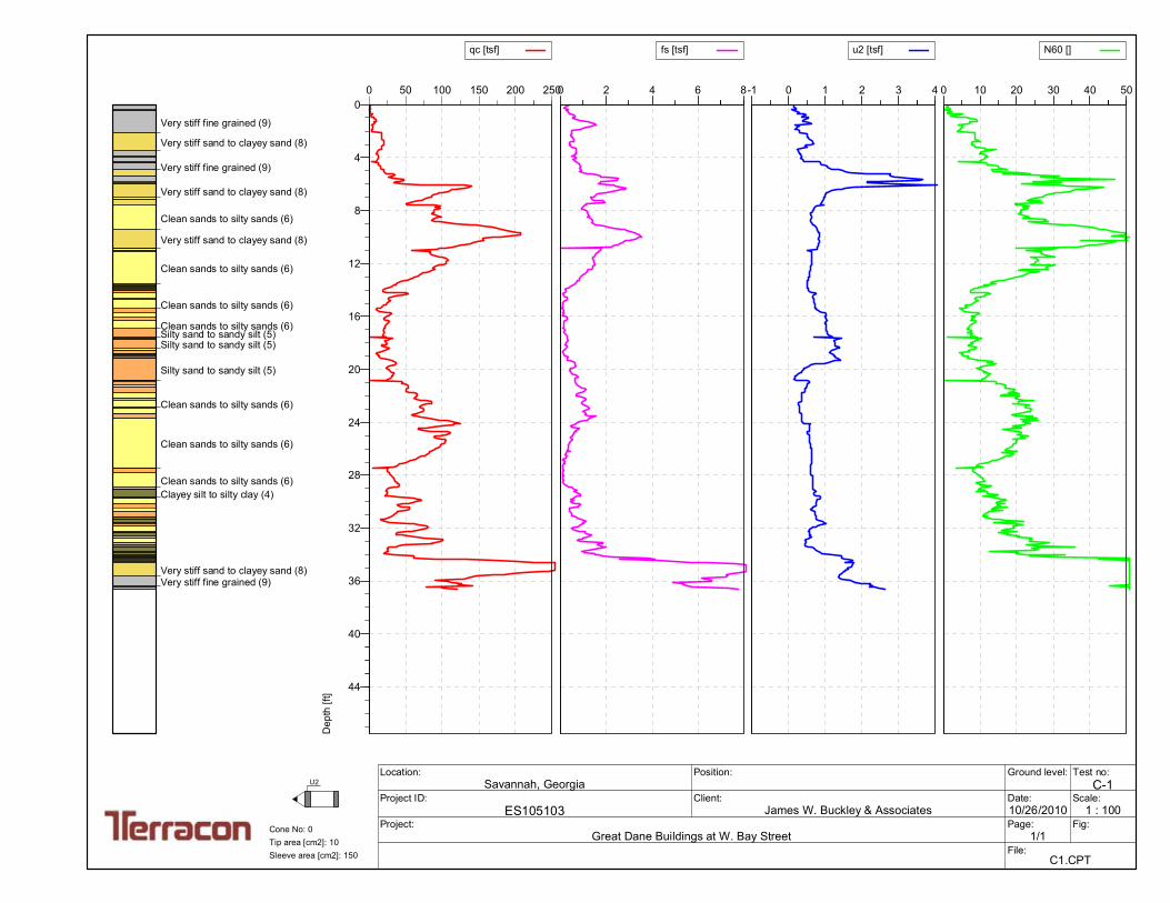
0 50 100 150 200 250
qc [tsf]
0
4
8
12
16
20
24
28
32
36
40
44
Dep
th [f
t]
0 2 4 6 8
fs [tsf]
-1 0 1 2 3 4
u2 [tsf]
0 10 20 30 40 50
N60 []
Test no:C-1
Project ID:ES105103
Client:James W. Buckley & Associates
Project:Great Dane Buildings at W. Bay Street
Position:Location:Savannah, Georgia
Ground level:
Date:10/26/2010
Scale:1 : 100
Page: 1/1
Fig:
File: C1.CPT
U2
Sleeve area [cm2]: 150Tip area [cm2]: 10Cone No: 0
Very stiff fine grained (9)
Very stiff sand to clayey sand (8)
Very stiff fine grained (9)
Very stiff sand to clayey sand (8)
Clean sands to silty sands (6)
Very stiff sand to clayey sand (8)
Clean sands to silty sands (6)
Clean sands to silty sands (6)
Clean sands to silty sands (6)Silty sand to sandy silt (5)Silty sand to sandy silt (5)
Silty sand to sandy silt (5)
Clean sands to silty sands (6)
Clean sands to silty sands (6)
Clean sands to silty sands (6)Clayey silt to silty clay (4)
Very stiff sand to clayey sand (8)Very stiff fine grained (9)
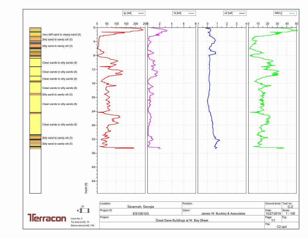
0 50 100 150 200 250
qc [tsf]
0
4
8
12
16
20
24
28
32
36
40
44
Dep
th [f
t]
0 2 4 6 8
fs [tsf]
-1 0 1 2 3 4
u2 [tsf]
0 10 20 30 40 50
N60 []
Test no:C-2
Project ID:ES105103
Client:James W. Buckley & Associates
Project:Great Dane Buildings at W. Bay Street
Position:Location:Savannah, Georgia
Ground level:
Date:10/27/2010
Scale:1 : 100
Page: 1/1
Fig:
File: C2.cpd
U2
Sleeve area [cm2]: 150Tip area [cm2]: 10Cone No: 0
Very stiff sand to clayey sand (8)
Silty sand to sandy silt (5)
Silty sand to sandy silt (5)
Clean sands to silty sands (6)
Clean sands to silty sands (6)
Clean sands to silty sands (6)
Clean sands to silty sands (6)
Silty sand to sandy silt (5)
Clean sands to silty sands (6)
Clean sands to silty sands (6)
Silty sand to sandy silt (5)
Silty sand to sandy silt (5)
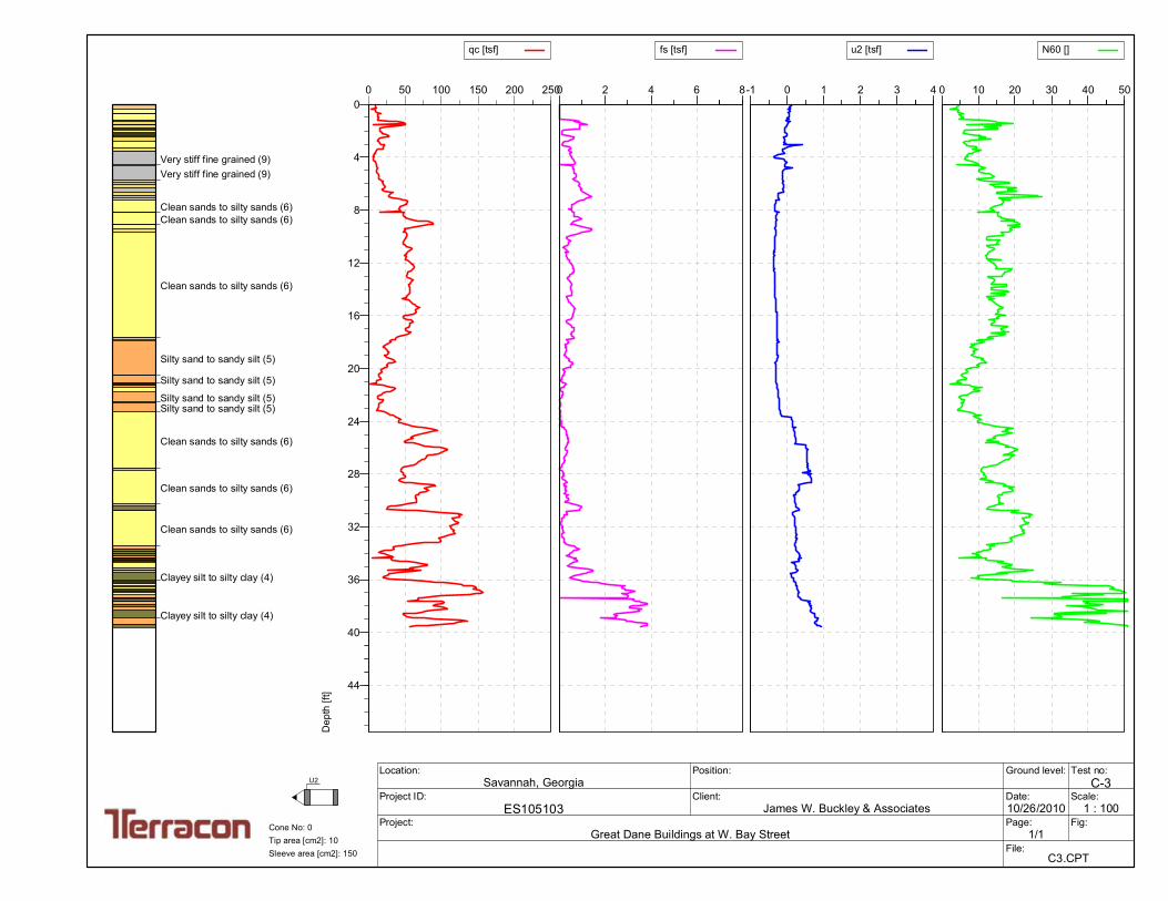
0 50 100 150 200 250
qc [tsf]
0
4
8
12
16
20
24
28
32
36
40
44
Dep
th [f
t]
0 2 4 6 8
fs [tsf]
-1 0 1 2 3 4
u2 [tsf]
0 10 20 30 40 50
N60 []
Test no:C-3
Project ID:ES105103
Client:James W. Buckley & Associates
Project:Great Dane Buildings at W. Bay Street
Position:Location:Savannah, Georgia
Ground level:
Date:10/26/2010
Scale:1 : 100
Page: 1/1
Fig:
File: C3.CPT
U2
Sleeve area [cm2]: 150Tip area [cm2]: 10Cone No: 0
Very stiff fine grained (9)Very stiff fine grained (9)
Clean sands to silty sands (6)Clean sands to silty sands (6)
Clean sands to silty sands (6)
Silty sand to sandy silt (5)
Silty sand to sandy silt (5)
Silty sand to sandy silt (5)Silty sand to sandy silt (5)
Clean sands to silty sands (6)
Clean sands to silty sands (6)
Clean sands to silty sands (6)
Clayey silt to silty clay (4)
Clayey silt to silty clay (4)
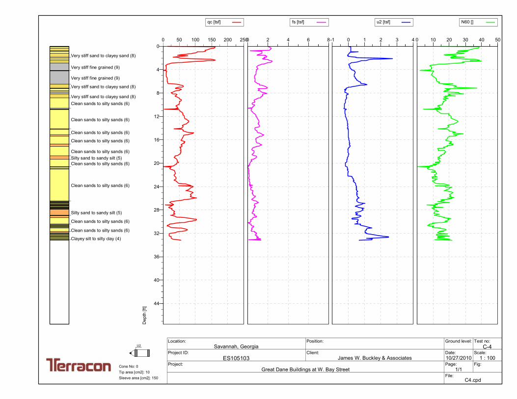
0 50 100 150 200 250
qc [tsf]
0
4
8
12
16
20
24
28
32
36
40
44
Dep
th [f
t]
0 2 4 6 8
fs [tsf]
-1 0 1 2 3 4
u2 [tsf]
0 10 20 30 40 50
N60 []
Test no:C-4
Project ID:ES105103
Client:James W. Buckley & Associates
Project:Great Dane Buildings at W. Bay Street
Position:Location:Savannah, Georgia
Ground level:
Date:10/27/2010
Scale:1 : 100
Page: 1/1
Fig:
File: C4.cpd
U2
Sleeve area [cm2]: 150Tip area [cm2]: 10Cone No: 0
Very stiff sand to clayey sand (8)
Very stiff fine grained (9)
Very stiff fine grained (9)
Very stiff sand to clayey sand (8)
Very stiff sand to clayey sand (8)Clean sands to silty sands (6)
Clean sands to silty sands (6)
Clean sands to silty sands (6)
Clean sands to silty sands (6)
Clean sands to silty sands (6)Silty sand to sandy silt (5)Clean sands to silty sands (6)
Clean sands to silty sands (6)
Silty sand to sandy silt (5)
Clean sands to silty sands (6)
Clean sands to silty sands (6)
Clayey silt to silty clay (4)
0 50 100 150 200 250
qc [tsf]
0
4
8
12
16
20
24
28
32
36
40
44
Dep
th [f
t]
0 2 4 6 8
fs [tsf]
-1 0 1 2 3 4
u2 [tsf]
0 10 20 30 40 50
N60 []
Test no:C-5
Project ID:ES105103
Client:James W. Buckley & Associates
Project:Great Dane Buildings at W. Bay Street
Position:Location:Savannah, Georgia
Ground level:
Date:10/26/2010
Scale:1 : 100
Page: 1/1
Fig:
File: C5.cpd
U2
Sleeve area [cm2]: 150Tip area [cm2]: 10Cone No: 0
Gravelly sand to sand (7)Very stiff sand to clayey sand (8)Clean sands to silty sands (6)
Very stiff fine grained (9)
Very stiff fine grained (9)
Clean sands to silty sands (6)
Clean sands to silty sands (6)
Silty sand to sandy silt (5)Silty sand to sandy silt (5)
Clean sands to silty sands (6)
Silty sand to sandy silt (5)
Clean sands to silty sands (6)Clean sands to silty sands (6)Clean sands to silty sands (6)Clean sands to silty sands (6)
Clean sands to silty sands (6)
Silty sand to sandy silt (5)
Clean sands to silty sands (6)
Silty sand to sandy silt (5)Silty sand to sandy silt (5)
Very stiff sand to clayey sand (8)Very stiff sand to clayey sand (8)Very stiff fine grained (9)
0 50 100 150 200 250
qc [tsf]
0
4
8
12
16
20
24
28
32
36
40
44
Dep
th [f
t]
0 2 4 6 8
fs [tsf]
-1 0 1 2 3 4
u2 [tsf]
0 10 20 30 40 50
N60 []
Test no:C-6
Project ID:ES105103
Client:James W. Buckley & Associates
Project:Great Dane Buildings at W. Bay Street
Position:Location:Savannah, Georgia
Ground level:
Date:10/26/2010
Scale:1 : 100
Page: 1/1
Fig:
File: C6.cpd
U2
Sleeve area [cm2]: 150Tip area [cm2]: 10Cone No: 0
Very stiff fine grained (9)
Very stiff sand to clayey sand (8)
Very stiff fine grained (9)
Very stiff sand to clayey sand (8)Clean sands to silty sands (6)
Clean sands to silty sands (6)
Clean sands to silty sands (6)
Clean sands to silty sands (6)
Silty sand to sandy silt (5)
Clayey silt to silty clay (4)
Silty sand to sandy silt (5)Clean sands to silty sands (6)
Silty sand to sandy silt (5)
Silty sand to sandy silt (5)
Clean sands to silty sands (6)Clayey silt to silty clay (4)
Clays; clay to silty clay (3)
0 50 100 150 200 250
qc [tsf]
0
4
8
12
16
20
24
28
32
36
40
44
Dep
th [f
t]
0 2 4 6 8
fs [tsf]
-1 0 1 2 3 4
u2 [tsf]
0 10 20 30 40 50
N60 []
Test no:C-7
Project ID:ES105103
Client:James W. Buckley & Associates
Project:Great Dane Buildings at W. Bay Street
Position:Location:Savannah, Georgia
Ground level:
Date:10/26/2010
Scale:1 : 100
Page: 1/1
Fig:
File: C7.cpd
U2
Sleeve area [cm2]: 150Tip area [cm2]: 10Cone No: 0
Gravelly sand to sand (7)
Clean sands to silty sands (6)
Very stiff fine grained (9)
Clayey silt to silty clay (4)
Clean sands to silty sands (6)
Clean sands to silty sands (6)
Clean sands to silty sands (6)
Silty sand to sandy silt (5)Silty sand to sandy silt (5)Clean sands to silty sands (6)
Silty sand to sandy silt (5)Clayey silt to silty clay (4)Silty sand to sandy silt (5)Silty sand to sandy silt (5)
Clean sands to silty sands (6)
Clean sands to silty sands (6)
Clean sands to silty sands (6)
Clean sands to silty sands (6)
Clean sands to silty sands (6)
0 50 100 150 200 250
qc [tsf]
0
4
8
12
16
20
24
28
32
36
40
44
Dep
th [f
t]
0 2 4 6 8
fs [tsf]
-1 0 1 2 3 4
u2 [tsf]
0 10 20 30 40 50
N60 []
Test no:C-8
Project ID:ES105103
Client:James W. Buckley & Associates
Project:Great Dane Buildings at W. Bay Street
Position:Location:Savannah, Georgia
Ground level:
Date:10/26/2010
Scale:1 : 100
Page: 1/1
Fig:
File: C8.cpd
U2
Sleeve area [cm2]: 150Tip area [cm2]: 10Cone No: 0
Gravelly sand to sand (7)Clean sands to silty sands (6)Gravelly sand to sand (7)Clean sands to silty sands (6)
Clays; clay to silty clay (3)
Very stiff fine grained (9)Very stiff fine grained (9)
Clean sands to silty sands (6)
Silty sand to sandy silt (5)Clean sands to silty sands (6)Clean sands to silty sands (6)Silty sand to sandy silt (5)Clayey silt to silty clay (4)
Silty sand to sandy silt (5)Silty sand to sandy silt (5)Clean sands to silty sands (6)
Clean sands to silty sands (6)
Clean sands to silty sands (6)Clean sands to silty sands (6)
Clean sands to silty sands (6)
Clean sands to silty sands (6)
Clean sands to silty sands (6)
Very stiff sand to clayey sand (8)
Sand Mixtures-Silty Sandto Sandy Silt
Sands-Clean Sand to SiltySand
Sands-Clean Sand to SiltySand
Sand Mixtures-Silty Sandto Sandy Silt
Sand Mixtures-Silty Sandto Sandy Silt
Sand Mixtures-Silty Sandto Sandy Silt
Clays-Clay to Silty Clay
Clays-Clay to Silty Clay
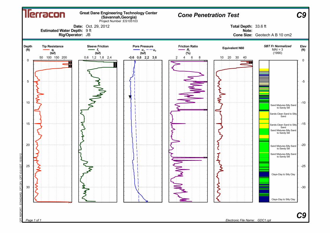
Electronic File Name: GDC1.cpt
Friction RatioRf
(%)2 4 6 8
Tip Resistanceqt
(tsf)50 100 150 200
Oct. 29, 2012
JB
33.6 ft
Great Dane Engineering Technology Center (Savannah,Georgia)
C9
Date:Estimated Water Depth:
Rig/Operator:
Project Number :ES105103
Page 1 of 1
Total Depth:Note:
Sleeve Frictionfs
(tsf)0.6 1.2 1.8 2.4 -0.6 0.8 2.2 3.6
Pore Pressureu2
(tsf)-0.6 0.8 2.2 3.6
u0
Geotech A B 10 cm29 ft
Cone Size:
Depth(ft)
0
5
10
15
20
25
30
CP
T R
EP
OR
T -
ST
AN
DA
RD
CP
T.G
PJ
CP
T V
3.0.
GD
T 1
0/30
/12
Elev(ft)
0
-5
-10
-15
-20
-25
-30
SBT Fr NormalizedMAI = 3(1990)
Equivalent N60
10 20 30 40>>
>>
>>>>
>>>>
>>>>>>>>>>>>>>>>>>>>>>>>>>>>>>>>>>
>>
>>>>>>>>>>>>>>>>>>>>>>>>>>>>>>>>>>>>
>>>>>>>>>>
Cone Penetration Test C9
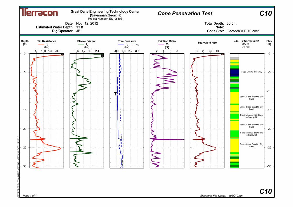
Clays-Clay to Silty Clay
Sands-Clean Sand to SiltySand
Sands-Clean Sand to SiltySand
Sand Mixtures-Silty Sandto Sandy Silt
Sands-Clean Sand to SiltySand
Sand Mixtures-Silty Sandto Sandy Silt
Sands-Clean Sand to SiltySand
Electronic File Name: 103C10.cpt
Friction RatioRf
(%)2 4 6 8
Tip Resistanceqt
(tsf)50 100 150 200
Nov. 12, 2012
JB
30.5 ft
Great Dane Engineering Technology Center (Savannah,Georgia)
C10
Date:Estimated Water Depth:
Rig/Operator:
Project Number :ES105103
Page 1 of 1
Total Depth:Note:
Sleeve Frictionfs
(tsf)0.6 1.2 1.8 2.4 -0.6 0.8 2.2 3.6
Pore Pressureu2
(tsf)-0.6 0.8 2.2 3.6
u0
Geotech A B 10 cm211 ft
Cone Size:
Depth(ft)
0
5
10
15
20
25
30
CP
T R
EP
OR
T -
ST
AN
DA
RD
CP
T.G
PJ
CP
T V
3.0.
GD
T 1
1/12
/12
Elev(ft)
0
-5
-10
-15
-20
-25
-30
SBT Fr NormalizedMAI = 3(1990)
Equivalent N60
10 20 30 40
>>
>>>>>>>>>> >>>>>>>>>>>>>>>>>>>>>>>>>>>>
Cone Penetration Test C10
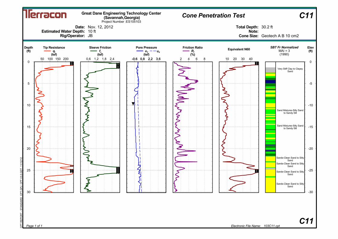
Very Stiff Clay to ClayeySand
Sand Mixtures-Silty Sandto Sandy Silt
Sand Mixtures-Silty Sandto Sandy Silt
Sands-Clean Sand to SiltySand
Sands-Clean Sand to SiltySand
Sands-Clean Sand to SiltySand
Sands-Clean Sand to SiltySand
Electronic File Name: 103C11.cpt
Friction RatioRf
(%)2 4 6 8
Tip Resistanceqt
(tsf)50 100 150 200
Nov. 12, 2012
JB
30.2 ft
Great Dane Engineering Technology Center (Savannah,Georgia)
C11
Date:Estimated Water Depth:
Rig/Operator:
Project Number :ES105103
Page 1 of 1
Total Depth:Note:
Sleeve Frictionfs
(tsf)0.6 1.2 1.8 2.4 -0.6 0.8 2.2 3.6
Pore Pressureu2
(tsf)-0.6 0.8 2.2 3.6
u0
Geotech A B 10 cm210 ft
Cone Size:
Depth(ft)
0
5
10
15
20
25
30
CP
T R
EP
OR
T -
ST
AN
DA
RD
CP
T.G
PJ
CP
T V
3.0.
GD
T 1
1/12
/12
Elev(ft)
0
-5
-10
-15
-20
-25
-30
SBT Fr NormalizedMAI = 3(1990)
Equivalent N60
10 20 30 40>>>>>>>>>>>>>>>>>>>>>>
>>>>>>>>>>>>>>>>>>>>>>>>
>>>>>>>>>>>>>>>>>>>>>>>>>>>>>>
>>>>>>>>>>>>>>>>>>>>>>>>>>>>>>>>>>>>>>>>>>
>>>>>>>>>>>>>>>>>>>>
>>>>>>>>>>>>>>>>>>>>
Cone Penetration Test C11
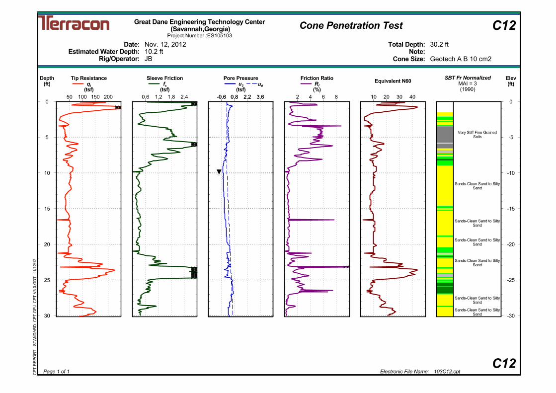
Very Stiff Fine GrainedSoils
Sands-Clean Sand to SiltySand
Sands-Clean Sand to SiltySand
Sands-Clean Sand to SiltySand
Sands-Clean Sand to SiltySand
Sands-Clean Sand to SiltySand
Sands-Clean Sand to SiltySand
Electronic File Name: 103C12.cpt
Friction RatioRf
(%)2 4 6 8
Tip Resistanceqt
(tsf)50 100 150 200
Nov. 12, 2012
JB
30.2 ft
Great Dane Engineering Technology Center (Savannah,Georgia)
C12
Date:Estimated Water Depth:
Rig/Operator:
Project Number :ES105103
Page 1 of 1
Total Depth:Note:
Sleeve Frictionfs
(tsf)0.6 1.2 1.8 2.4 -0.6 0.8 2.2 3.6
Pore Pressureu2
(tsf)-0.6 0.8 2.2 3.6
u0
Geotech A B 10 cm210.2 ft
Cone Size:
Depth(ft)
0
5
10
15
20
25
30
CP
T R
EP
OR
T -
ST
AN
DA
RD
CP
T.G
PJ
CP
T V
3.0.
GD
T 1
1/12
/12
Elev(ft)
0
-5
-10
-15
-20
-25
-30
SBT Fr NormalizedMAI = 3(1990)
Equivalent N60
10 20 30 40
>>
>>>>>>>>>>>>>>>>>>
>>>>>>>>>>>>
>>>>>>>>>>>>>>>>>>>>>>>>>>>>>>>>>>>>>>>>
Cone Penetration Test C12
Gravelly Sand to Sand
Very Stiff Fine GrainedSoils
Silt Mixtures-Clay Silt toSilty Clay
Sands-Clean Sand to SiltySand
Sands-Clean Sand to SiltySand
Sands-Clean Sand to SiltySand
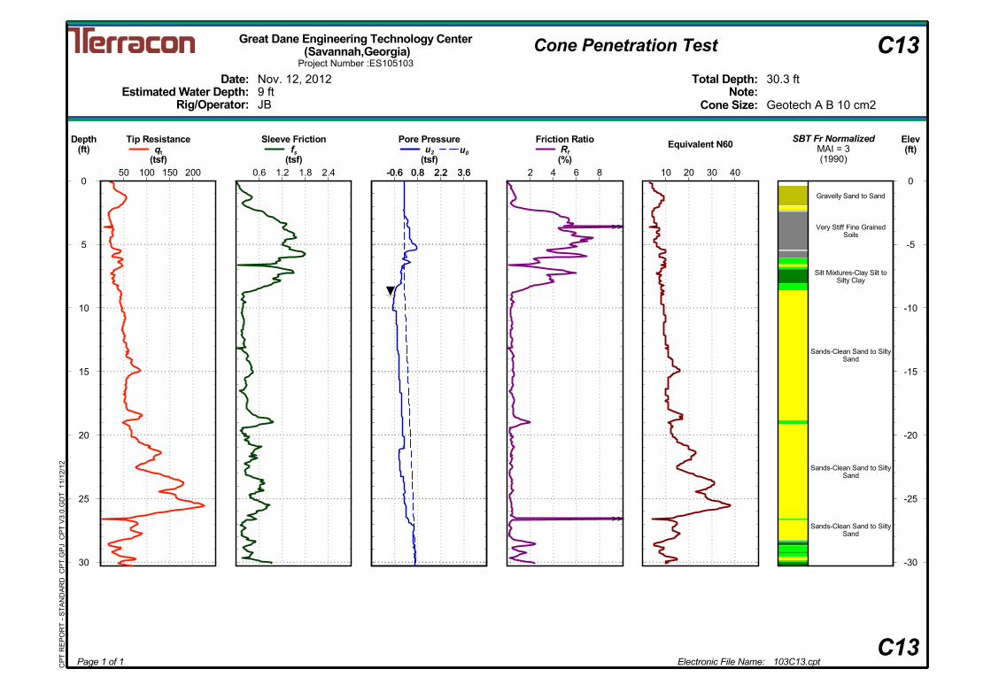
Electronic File Name: 103C13.cpt
Friction RatioRf
(%)2 4 6 8
Tip Resistanceqt
(tsf)50 100 150 200
Nov. 12, 2012
JB
30.3 ft
Great Dane Engineering Technology Center (Savannah,Georgia)
C13
Date:Estimated Water Depth:
Rig/Operator:
Project Number :ES105103
Page 1 of 1
Total Depth:Note:
Sleeve Frictionfs
(tsf)0.6 1.2 1.8 2.4 -0.6 0.8 2.2 3.6
Pore Pressureu2
(tsf)-0.6 0.8 2.2 3.6
u0
Geotech A B 10 cm29 ft
Cone Size:
Depth(ft)
0
5
10
15
20
25
30
CP
T R
EP
OR
T -
ST
AN
DA
RD
CP
T.G
PJ
CP
T V
3.0.
GD
T 1
1/12
/12
Elev(ft)
0
-5
-10
-15
-20
-25
-30
SBT Fr NormalizedMAI = 3(1990)
Equivalent N60
10 20 30 40
>>
>>
Cone Penetration Test C13
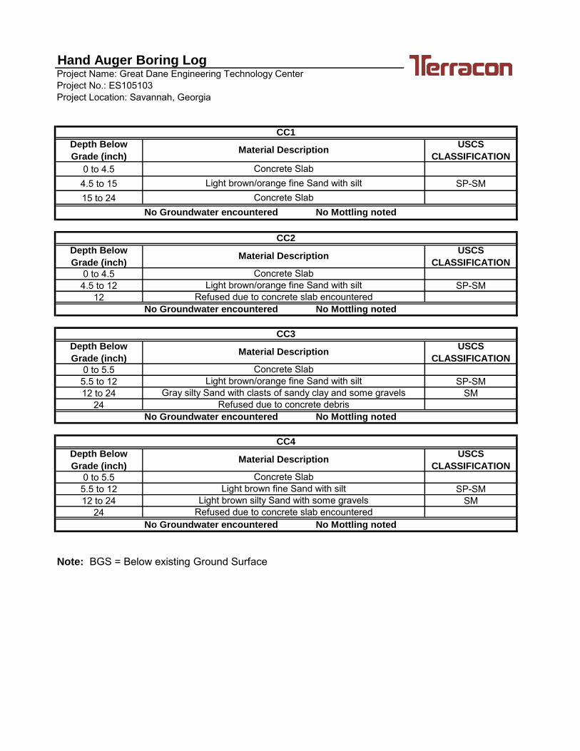
Project Name: Great Dane Engineering Technology CenterProject No.: ES105103Project Location: Savannah, Georgia
Depth Below
Grade (inch)
USCS
CLASSIFICATION
0 to 4.54.5 to 15 SP-SM15 to 24
Depth Below
Grade (inch)
USCS
CLASSIFICATION
0 to 4.54.5 to 12 SP-SM
12
Depth Below
Grade (inch)
USCS
CLASSIFICATION
0 to 5.55.5 to 12 SP-SM12 to 24 SM
24
Depth Below
Grade (inch)
USCS
CLASSIFICATION
0 to 5.55.5 to 12 SP-SM12 to 24 SM
24
Light brown/orange fine Sand with silt
Light brown/orange fine Sand with silt
Light brown/orange fine Sand with silt
Light brown fine Sand with silt
Concrete Slab
CC4
Concrete Slab
Concrete Slab
No Groundwater encountered No Mottling noted
Note: BGS = Below existing Ground Surface
Refused due to concrete slab encountered
Light brown silty Sand with some gravels
Refused due to concrete debris
No Mottling noted
Hand Auger Boring Log
No Groundwater encountered
No Groundwater encountered No Mottling noted
CC2
Material Description
CC1
Material Description
Concrete Slab
Gray silty Sand with clasts of sandy clay and some gravels
No Groundwater encountered
CC3
Material Description
Material Description
Concrete Slab
Refused due to concrete slab encountered
No Mottling noted
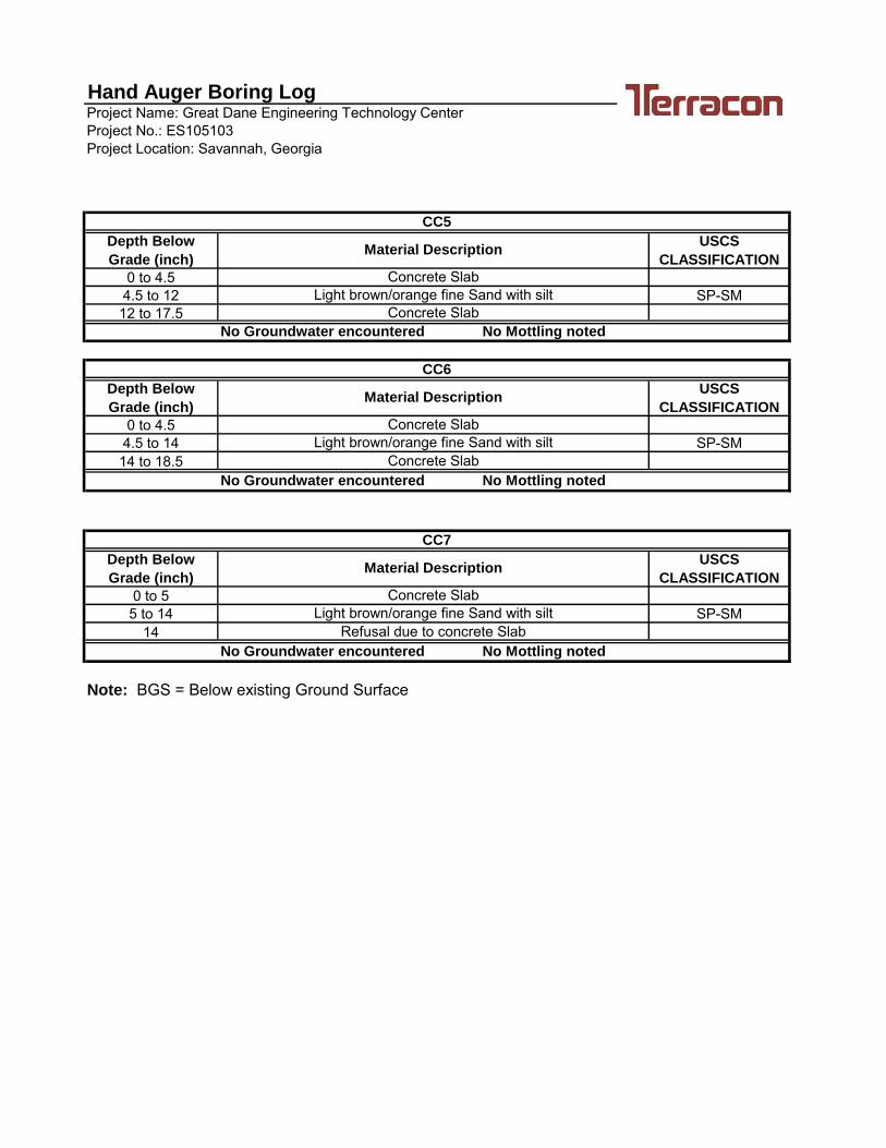
Project Name: Great Dane Engineering Technology CenterProject No.: ES105103Project Location: Savannah, Georgia
Depth Below
Grade (inch)
USCS
CLASSIFICATION
0 to 4.54.5 to 12 SP-SM12 to 17.5
Depth Below
Grade (inch)
USCS
CLASSIFICATION
0 to 4.54.5 to 14 SP-SM14 to 18.5
Depth Below
Grade (inch)
USCS
CLASSIFICATION
0 to 55 to 14 SP-SM
14
CC7
Refusal due to concrete SlabNo Groundwater encountered No Mottling noted
Note: BGS = Below existing Ground Surface
CC6
Material Description
Concrete SlabLight brown/orange fine Sand with silt
Concrete SlabNo Groundwater encountered No Mottling noted
CC5
Material Description
Concrete SlabLight brown/orange fine Sand with silt
Concrete SlabNo Groundwater encountered No Mottling noted
Material Description
Concrete SlabLight brown/orange fine Sand with silt
Hand Auger Boring Log
CONCRETE CORE TEST REPORT
Report Number:Service Date:Report Date:Task:
Client Project
Project Number:
ES105103.000110/25/1210/25/12
2201 Rowland Ave.Savannah, GA 31404912-629-4000
Great Dane TrailersAttn: Jay StricklandP.O. Box 67Savannah, GA 31402
ES105103
Savannah, GA 31415Intersection of W. Bay and E. Lathrop AveGreat Dane Buildings
Sample Information
Specified Strength:
Material Information
Specified Length:Mix ID:Nominal Maximum Size Aggregate:
Placement Date:Date Tested:Sampled By:Drill Directions:Date Core Obtained:Date Ends Trimmed:Moisture Conditioning History:
Time:
Time:Time:
N/A10/25/12 1500ContractorVertical
10/23/12 120010/25/12 1430
According to ASTM C-42
ID Location (in) (in) (in) (in) (sq in) Diam. Ratio (lbs) FactorCore
CoredLaboratory Test Data Trim CappedDiam. Area Length / Max Load Corr.
(psi)
Comp.
TypeFracture
(pcf)DensityLength Length Length Strength
1 N/A 4.1 3.8 4.1 3.75 11.03 1.09 100940 0.892 8170 22 N/A 4.6 4.4 4.7 3.75 11.03 1.25 103180 0.930 8700 23 N/A 5.5 5.3 5.5 3.75 11.03 1.48 54750 0.958 4760 24 N/A 5.1 5.0 5.2 3.75 11.03 1.39 54430 0.947 4670 25 N/A 4.8 4.6 4.9 3.75 11.03 1.30 89820 0.936 7620 26 N/A 4.8 4.7 5.0 3.75 11.03 1.34 45050 0.941 3840 27 N/A 5.0 5.0 5.2 3.75 11.03 1.40 55780 0.948 4800 2
Comments:
The tests were performed in general accordance with applicable ASTM, AASHTO, or DOT test methods. This report is exclusively for the use of the client indicated above and shall not be reproduced except in full without the written consent of our company. Test results transmitted herein are only applicable to the actual samples tested at the location(s) referenced and are not necessarily indicative of the properties of other apparently similar or identical materials.
CR0004, 8-27-11, Rev.4Page 1 of 2
CONCRETE CORE TEST REPORT
Report Number:Service Date:Report Date:Task:
Client Project
Project Number:
ES105103.000110/25/1210/25/12
2201 Rowland Ave.Savannah, GA 31404912-629-4000
Great Dane TrailersAttn: Jay StricklandP.O. Box 67Savannah, GA 31402
ES105103
Savannah, GA 31415Intersection of W. Bay and E. Lathrop AveGreat Dane Buildings
Services:
Reported To:Contractor:Report Distribution:
(1) Great Dane Trailers
Turner, GregoryConstruction Services Supervisor
Reviewed By:
Terracon Rep.: Darrell Williams
Test Methods: ASTM C39, ASTM C42, ASTM C174The tests were performed in general accordance with applicable ASTM, AASHTO, or DOT test methods. This report is exclusively for the use of the client indicated above and shall not be reproduced except in full without the written consent of our company. Test results transmitted herein are only applicable to the actual samples tested at the location(s) referenced and are not necessarily indicative of the properties of other apparently similar or identical materials.
CR0004, 8-27-11, Rev.4Page 2 of 2
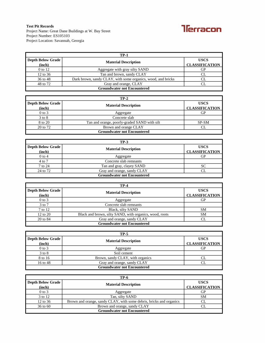
Test Pit RecordsProject Name: Great Dane Buildings at W. Bay StreetProject Number: ES105103Project Location: Savannah, Georgia
Depth Below Grade (inch)
USCS CLASSIFICATION
0 to 12 GP12 to 36 CL36 to 48 CL48 to 72 CL
Depth Below Grade (inch)
USCS CLASSIFICATION
0 to 3 GP3 to 8 8 to 20 SP-SM
20 to 72 CL
Depth Below Grade (inch)
USCS CLASSIFICATION
0 to 4 GP4 to 7 7 to 24 SC
24 to 72 CL
Depth Below Grade (inch)
USCS CLASSIFICATION
0 to 3 GP3 to 7
7 to 12 SM12 to 20 SM20 to 84 CL
Depth Below Grade (inch)
USCS CLASSIFICATION
0 to 3 GP3 to 8
8 to 16 CL16 to 48 CL
Depth Below Grade (inch)
USCS CLASSIFICATION
0 to 3 GP3 to 12 SM
12 to 36 CL36 to 60 CL
Brown and orange, sandy CLAY, with some debris, bricks and organics
Groundwater not Encountered
Brown, sandy CLAY, with organics
Groundwater not Encountered
TP-6
Material Description
AggregateTan, silty SAND
Gray and orange, sandy CLAY
Brown and orange, sandy CLAY
Black, silty SAND
Groundwater not Encountered
TP-5
Material Description
AggregateSoil cement
Black and brown, silty SAND, with organics, wood, rootsGray and orange, sandy CLAY
Tan and gray, clayey SAND
Groundwater not Encountered
TP-4
Material Description
AggregateConcrete slab remnants
Gray and orange, sandy CLAY
Aggregate
Material Description
Concrete slabTan and orange, poorly-graded SAND with silt
Groundwater not Encountered Brown and orange CLAY
TP-1
Material Description
Tan and brown, sandy CLAYDark brown, sandy CLAY, with some organics, wood, and bricks
Groundwater not Encountered Gray and orange, CLAY
TP-2
Aggregate with gray silty SAND
TP-3
Material Description
AggregateConcrete slab remnants
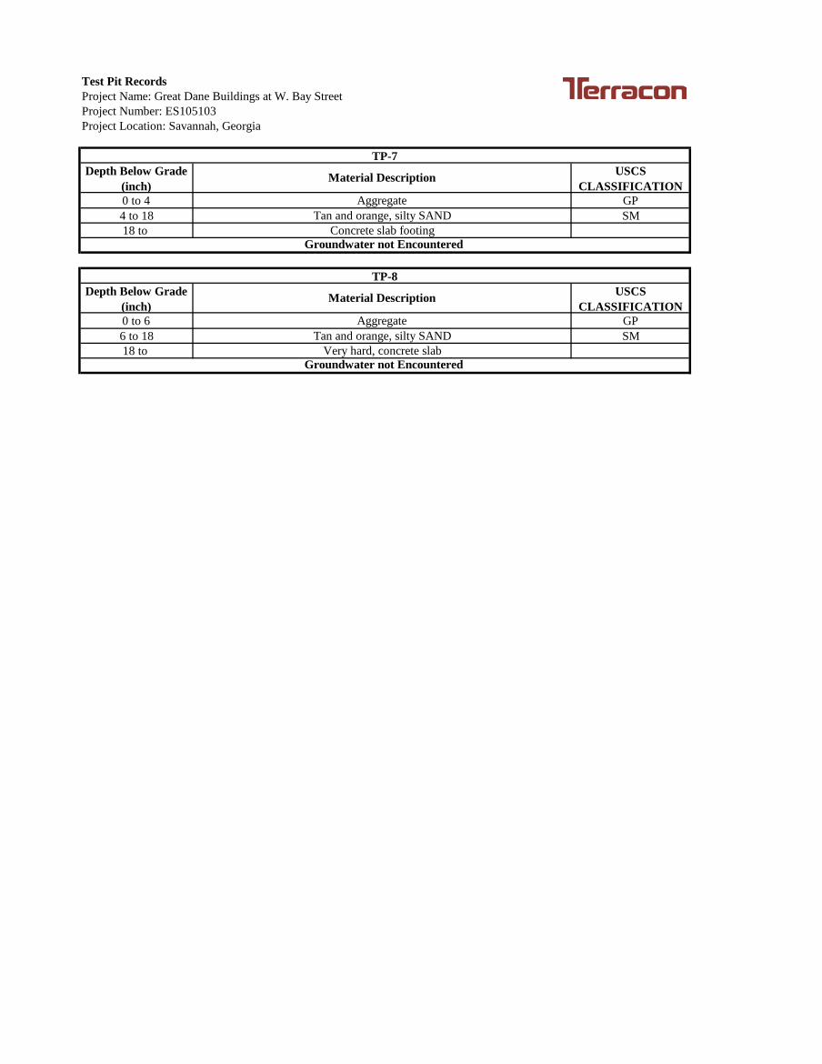
Test Pit RecordsProject Name: Great Dane Buildings at W. Bay StreetProject Number: ES105103Project Location: Savannah, Georgia
Depth Below Grade (inch)
USCS CLASSIFICATION
0 to 4 GP4 to 18 SM18 to
Depth Below Grade (inch)
USCS CLASSIFICATION
0 to 6 GP6 to 18 SM18 to
TP-7
Material Description
AggregateTan and orange, silty SAND
Very hard, concrete slabGroundwater not Encountered
Concrete slab footingGroundwater not Encountered
TP-8
Material Description
AggregateTan and orange, silty SAND
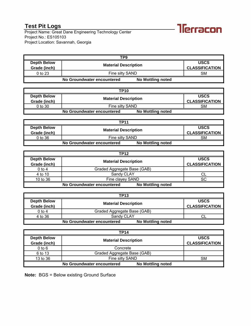
Project Name: Great Dane Engineering Technology CenterProject No.: ES105103Project Location: Savannah, Georgia
Depth Below
Grade (inch)
USCS
CLASSIFICATION
0 to 23 SM
Depth Below
Grade (inch)
USCS
CLASSIFICATION
0 to 30 SM
Depth Below
Grade (inch)
USCS
CLASSIFICATION
0 to 36 SM
Depth Below
Grade (inch)
USCS
CLASSIFICATION
0 to 44 to 10 CL10 to 36 SC
Depth Below
Grade (inch)
USCS
CLASSIFICATION
0 to 44 to 36 CL
Depth Below
Grade (inch)
USCS
CLASSIFICATION
0 to 66 to 1313 to 36 SM
Graded Aggregate Base (GAB)
TP12
No Groundwater encountered No Mottling noted
No Groundwater encountered No Mottling noted
TP14
Material Description
Concrete
Fine silty SAND
No Groundwater encountered No Mottling noted
Note: BGS = Below existing Ground Surface
Fine silty SAND
Sandy CLAY
Sandy CLAYGraded Aggregate Base (GAB)
Fine silty SAND
No Mottling noted
Test Pit Logs
No Groundwater encountered
No Groundwater encountered No Mottling noted
TP10
Material Description
TP9
Material Description
Fine silty SAND
TP13
Material Description
No Groundwater encountered
TP11
Material Description
Material Description
Graded Aggregate Base (GAB)
Fine clayey SAND
No Mottling noted
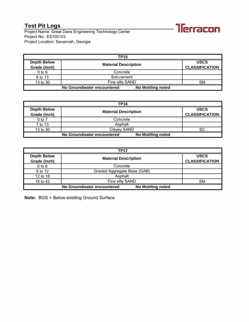
Project Name: Great Dane Engineering Technology CenterProject No.: ES105103Project Location: Savannah, Georgia
Depth Below
Grade (inch)
USCS
CLASSIFICATION
0 to 66 to 1313 to 30 SM
Depth Below
Grade (inch)
USCS
CLASSIFICATION
0 to 77 to 1313 to 30 SC
Depth Below
Grade (inch)
USCS
CLASSIFICATION
0 to 66 to 1212 to 1818 to 42 SM
Note: BGS = Below existing Ground Surface
Asphalt
Material Description
ConcreteGraded Aggregate Base (GAB)
Fine silty SANDNo Groundwater encountered No Mottling noted
Material Description
Concrete
Clayey SANDNo Groundwater encountered No Mottling noted
TP17
ConcreteSoil-cement
Fine silty SANDNo Groundwater encountered No Mottling noted
TP16
Asphalt
TP15
Material Description
Test Pit Logs
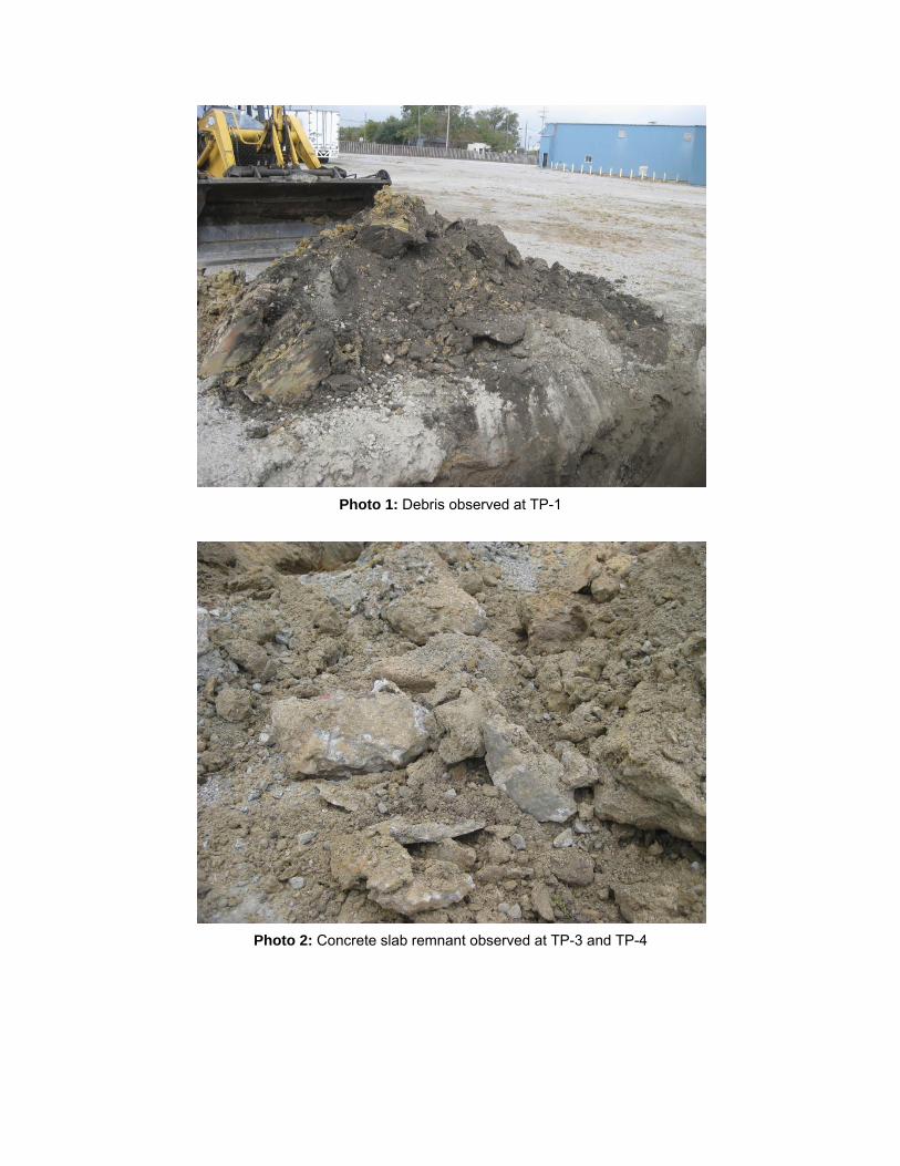
Photo 2: Concrete slab remnant observed at TP-3 and TP-4
Photo 1: Debris observed at TP-1
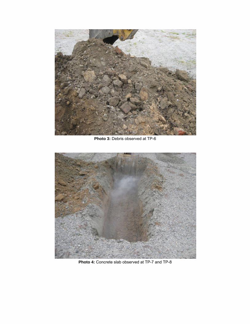
Photo 3: Debris observed at TP-6
Photo 4: Concrete slab observed at TP-7 and TP-8
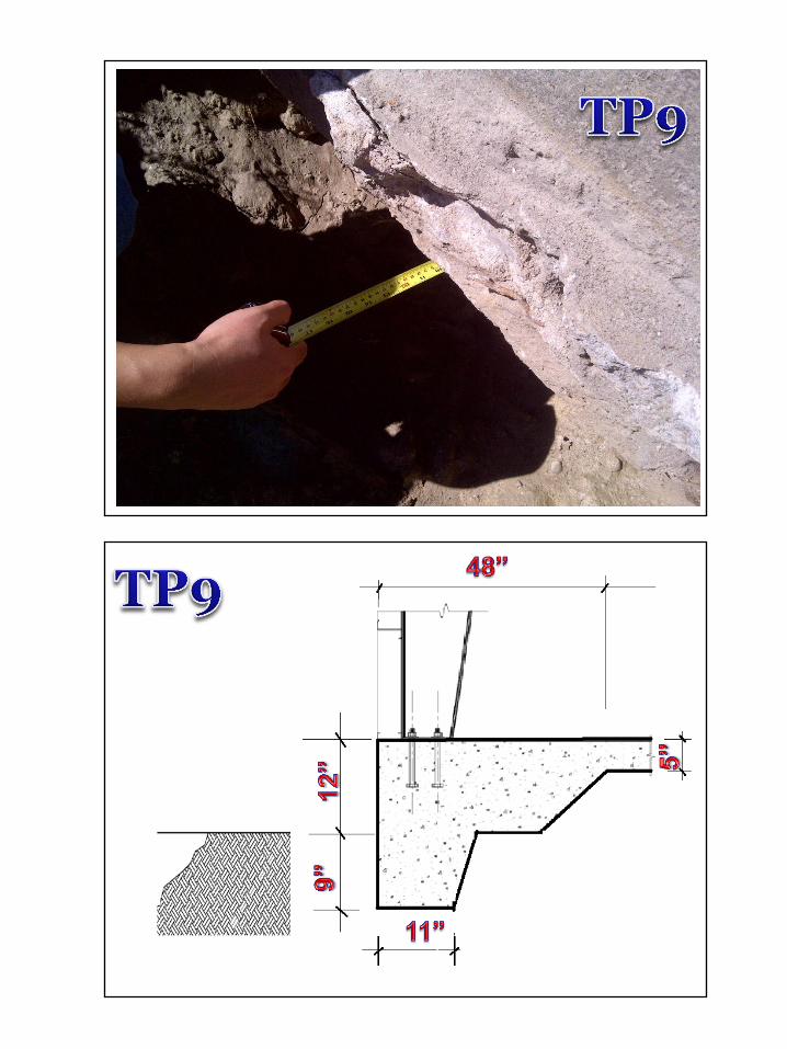
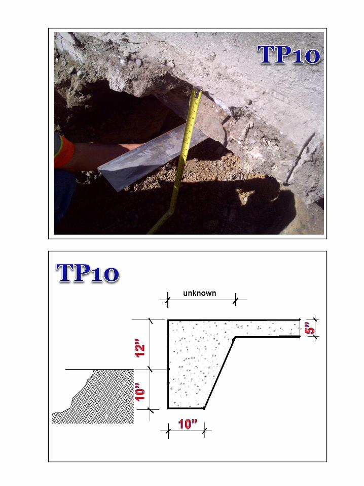
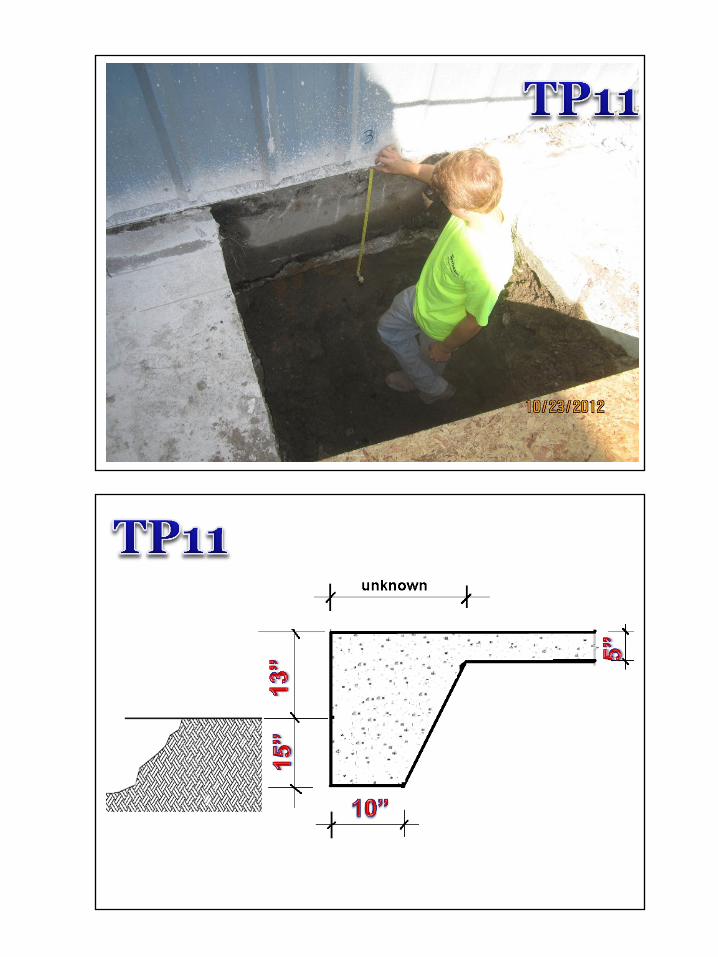
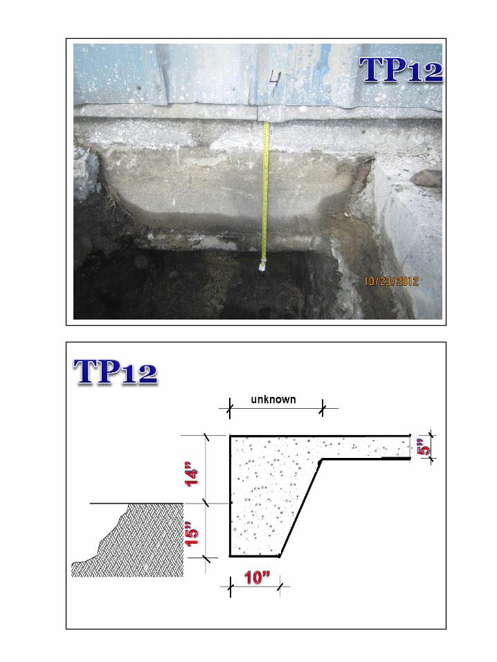
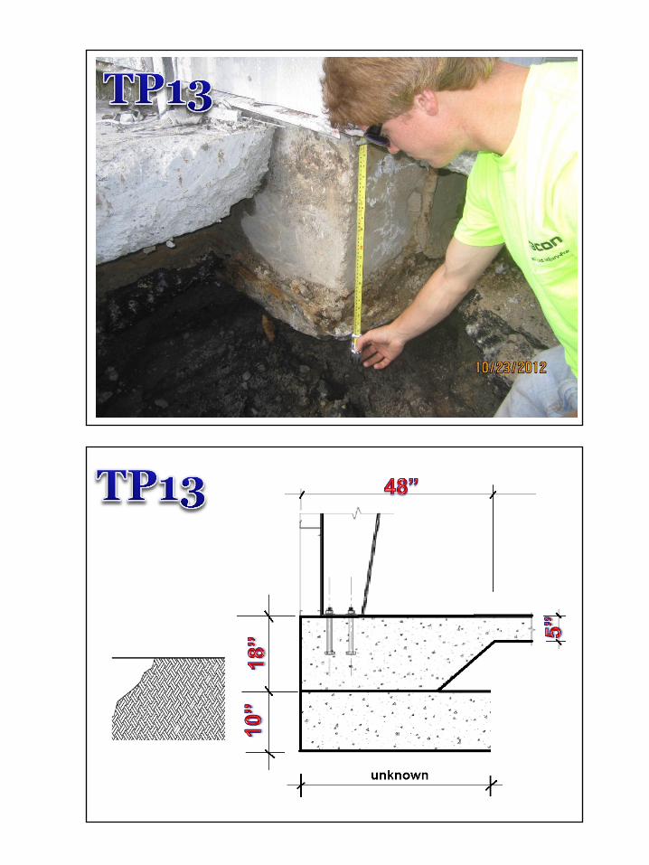
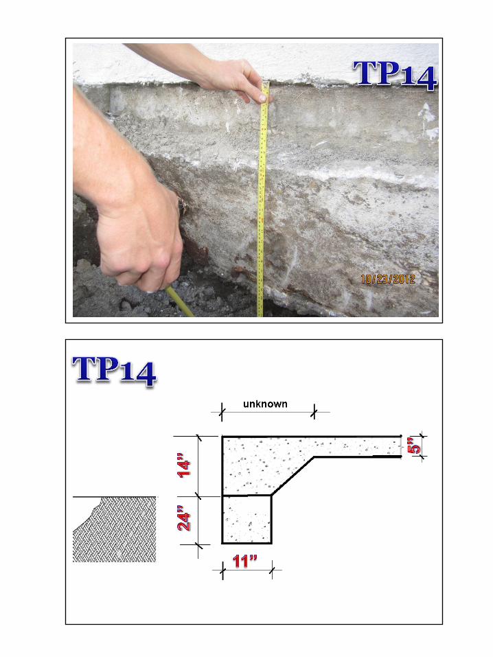
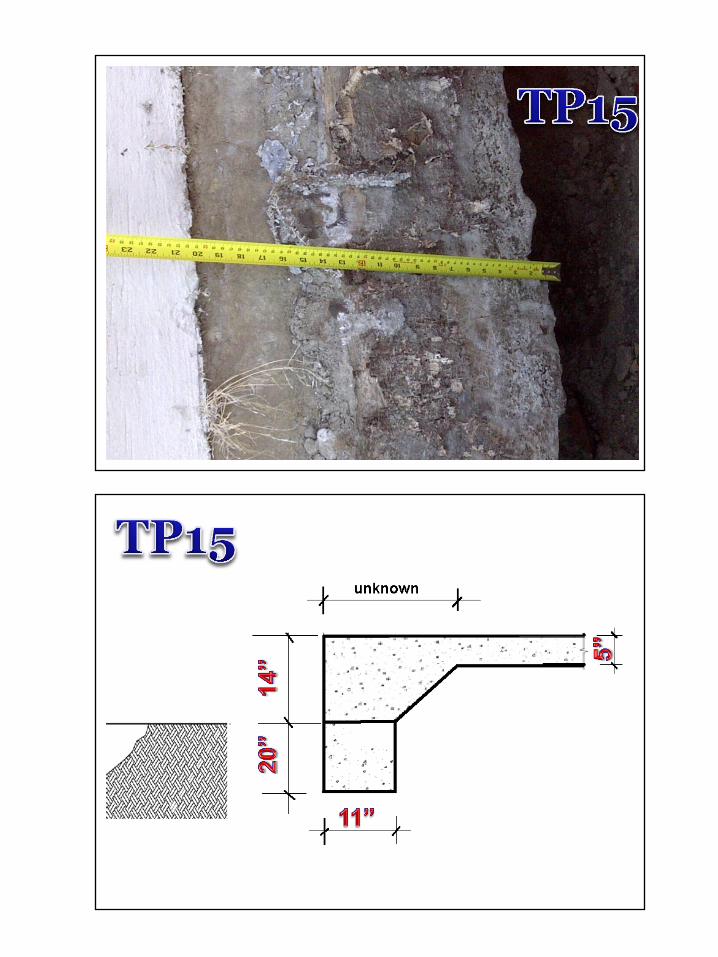
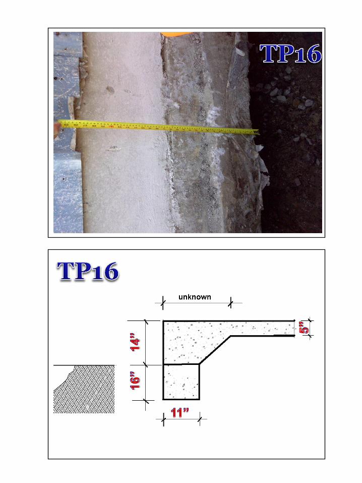
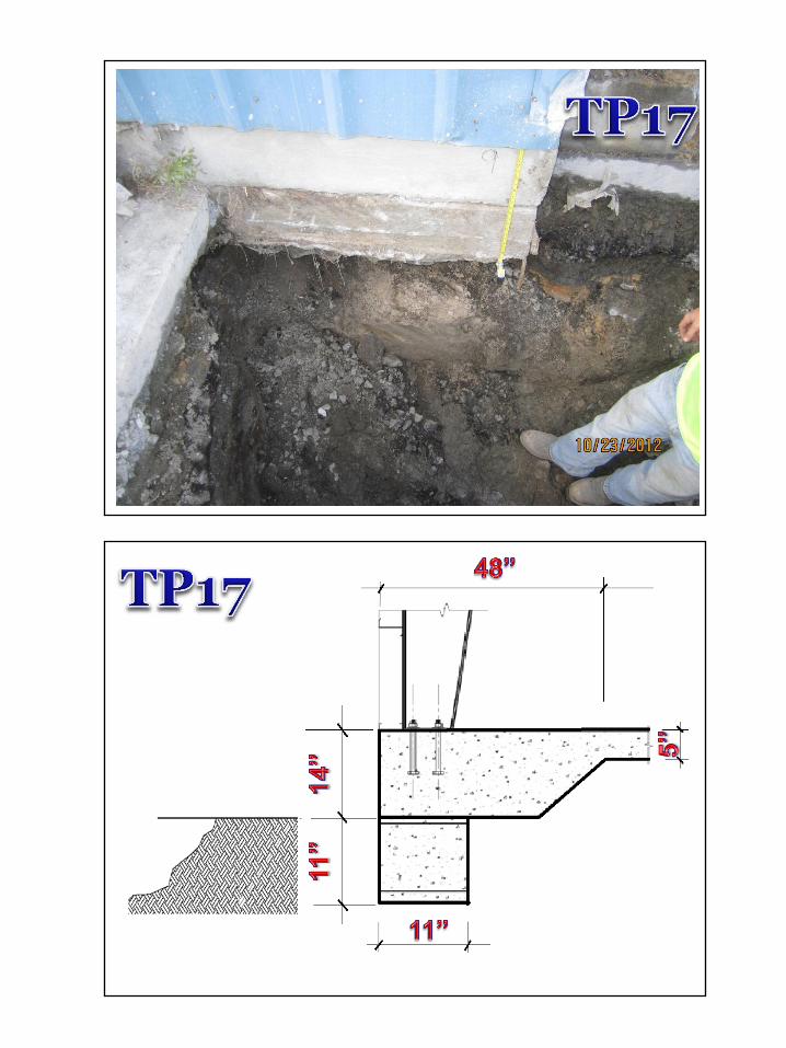
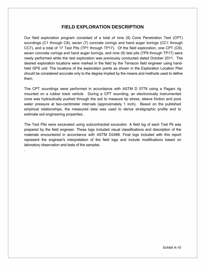
Exhibit A-10
FIELD EXPLORATION DESCRIPTION Our field exploration program consisted of a total of nine (9) Cone Penetration Test (CPT) soundings (C1 through C9), seven (7) concrete corings and hand auger borings (CC1 through CC7), and a total of 17 Test Pits (TP1 through TP17). Of the field exploration, one CPT (C9), seven concrete corings and hand auger borings, and nine (9) test pits (TP9 through TP17) were newly performed while the rest exploration was previously conducted dated October 2011. The desired exploration locations were marked in the field by the Terracon field engineer using hand-held GPS unit. The locations of the exploration points as shown in the Exploration Location Plan should be considered accurate only to the degree implied by the means and methods used to define them. The CPT soundings were performed in accordance with ASTM D 5778 using a Pagani rig mounted on a rubber track vehicle. During a CPT sounding, an electronically instrumented cone was hydraulically pushed through the soil to measure tip stress, sleeve friction and pore water pressure at two-centimeter intervals (approximately 1 inch). Based on the published empirical relationships, the measured data was used to derive stratigraphic profile and to estimate soil engineering properties. The Test Pits were excavated using subcontracted excavator. A field log of each Test Pit was prepared by the field engineer. These logs included visual classifications and description of the materials encountered in accordance with ASTM D2488. Final logs included with this report represent the engineer's interpretation of the field logs and include modifications based on laboratory observation and tests of the samples. .

APPENDIX B
SUPPORTING INFORMATION
Exhibit B-1 Seismic Design Parameters Exhibit B-2 General Notes Exhibit B-3 Unified Soil Classification System
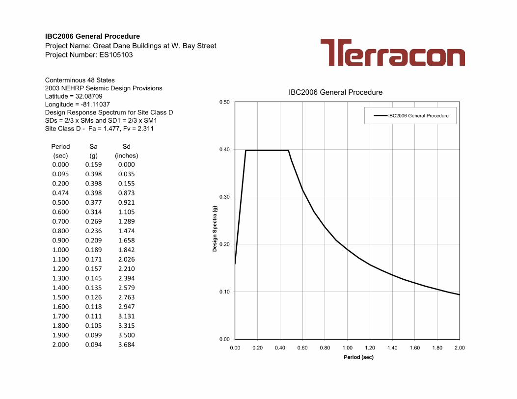
IBC2006 General Procedure
Project Name: Great Dane Buildings at W. Bay StreetProject Number: ES105103
Conterminous 48 States2003 NEHRP Seismic Design ProvisionsLatitude = 32.08709Longitude = -81.11037Design Response Spectrum for Site Class DSDs = 2/3 x SMs and SD1 = 2/3 x SM1Site Class D - Fa = 1.477, Fv = 2.311
Period Sa Sd(sec) (g) (inches)0.000 0.159 0.0000.095 0.398 0.0350.200 0.398 0.1550.474 0.398 0.8730.500 0.377 0.9210.600 0.314 1.1050.700 0.269 1.2890.800 0.236 1.4740.900 0.209 1.6581.000 0.189 1.8421.100 0.171 2.0261.200 0.157 2.2101.300 0.145 2.3941.400 0.135 2.5791.500 0.126 2.7631.600 0.118 2.9471.700 0.111 3.1311.800 0.105 3.3151.900 0.099 3.5002.000 0.094 3.684
0.00
0.10
0.20
0.30
0.40
0.50
0.00 0.20 0.40 0.60 0.80 1.00 1.20 1.40 1.60 1.80 2.00
Desig
n S
pectr
a (
g)
Period (sec)
IBC2006 General Procedure
IBC2006 General Procedure
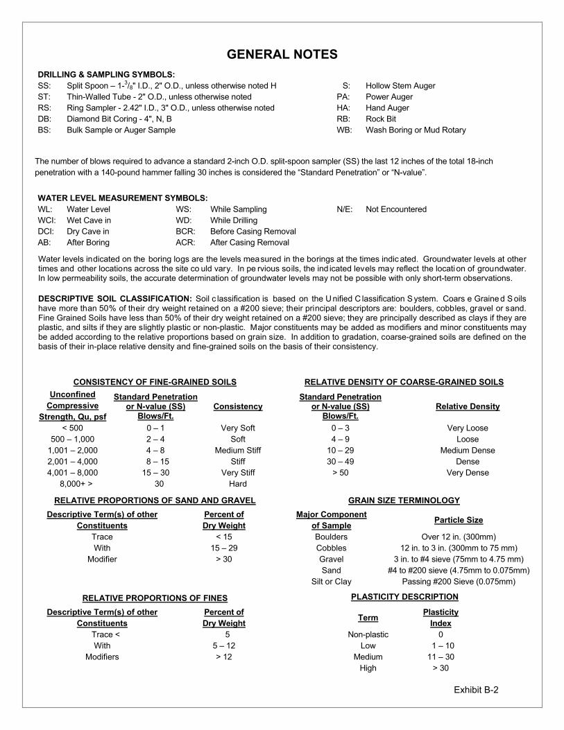
Exhibit B-2
GENERAL NOTES
DRILLING & SAMPLING SYMBOLS: SS: Split Spoon – 1-3/8" I.D., 2" O.D., unless otherwise noted H S: Hollow Stem Auger ST: Thin-Walled Tube - 2" O.D., unless otherwise noted PA: Power Auger RS: Ring Sampler - 2.42" I.D., 3" O.D., unless otherwise noted HA: Hand Auger DB: Diamond Bit Coring - 4", N, B RB: Rock Bit BS: Bulk Sample or Auger Sample WB: Wash Boring or Mud Rotary
The number of blows required to advance a standard 2-inch O.D. split-spoon sampler (SS) the last 12 inches of the total 18-inch penetration with a 140-pound hammer falling 30 inches is considered the “Standard Penetration” or “N-value”.
WATER LEVEL MEASUREMENT SYMBOLS: WL: Water Level WS: While Sampling N/E: Not Encountered WCI: Wet Cave in WD: While Drilling DCI: Dry Cave in BCR: Before Casing Removal AB: After Boring ACR: After Casing Removal
Water levels indicated on the boring logs are the levels measured in the borings at the times indic ated. Groundwater levels at other times and other locations across the site co uld vary. In pe rvious soils, the ind icated levels may reflect the locati on of groundwater. In low permeability soils, the accurate determination of groundwater levels may not be possible with only short-term observations.
DESCRIPTIVE SOIL CLASSIFICATION: Soil c lassification is based on the U nified C lassification S ystem. Coars e Graine d S oils have more than 50% of their dry weight retained on a #200 sieve; their principal descriptors are: boulders, cobbles, gravel or sand. Fine Grained Soils have less than 50% of their dry weight retained on a #200 sieve; they are principally described as clays if they are plastic, and silts if they are slightly plastic or non-plastic. Major constituents may be added as modifiers and minor constituents may be added according to the relative proportions based on grain size. In addition to gradation, coarse-grained soils are defined on the basis of their in-place relative density and fine-grained soils on the basis of their consistency.
CONSISTENCY OF FINE-GRAINED SOILS RELATIVE DENSITY OF COARSE-GRAINED SOILS
Unconfined Compressive
Strength, Qu, psf
Standard Penetration or N-value (SS)
Blows/Ft. Consistency
Standard Penetration or N-value (SS)
Blows/Ft. Relative Density
< 500 0 – 1 Very Soft 0 – 3 Very Loose 500 – 1,000 2 – 4 Soft 4 – 9 Loose
1,001 – 2,000 4 – 8 Medium Stiff 10 – 29 Medium Dense 2,001 – 4,000 8 – 15 Stiff 30 – 49 Dense 4,001 – 8,000 15 – 30 Very Stiff > 50 Very Dense
8,000+ > 30 Hard
RELATIVE PROPORTIONS OF SAND AND GRAVEL GRAIN SIZE TERMINOLOGY
Descriptive Term(s) of other Constituents
Percent ofDry Weight
Major Componentof Sample
Particle Size
Trace < 15 Boulders Over 12 in. (300mm) With 15 – 29 Cobbles 12 in. to 3 in. (300mm to 75 mm)
Modifier > 30 Gravel 3 in. to #4 sieve (75mm to 4.75 mm) Sand #4 to #200 sieve (4.75mm to 0.075mm) Silt or Clay Passing #200 Sieve (0.075mm)
RELATIVE PROPORTIONS OF FINES PLASTICITY DESCRIPTION
Descriptive Term(s) of other Constituents
Percent ofDry Weight
Term Plasticity
Index
Trace < 5 Non-plastic 0 With 5 – 12 Low 1 – 10
Modifiers > 12 Medium 11 – 30 High > 30
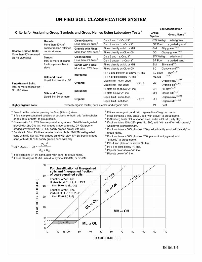
Exhibit B-3
UNIFIED SOIL CLASSIFICATION SYSTEM
Criteria for Assigning Group Symbols and Group Names Using Laboratory Tests A Soil Classification
Group Symbol
Group Name B
Coarse Grained Soils: More than 50% retained on No. 200 sieve
Gravels: More than 50% of coarse fraction retained on No. 4 sieve
Clean Gravels: Less than 5% fines C
Cu ≥ 4 and 1 ≤ Cc ≤ 3 E GW Well-gr aded gravel F Cu < 4 and/or 1 > Cc > 3 E GP Poorl y graded gravel F
Gravels with Fines: More than 12% fines C
Fines classify as ML or MH GM Silty gravel F,G,H Fines classify as CL or CH GC Clayey gravel F,G,H
Sands: 50% or more of coarse fraction passes No. 4 sieve
Clean Sands: Less than 5% fines D
Cu ≥ 6 and 1 ≤ Cc ≤ 3 E SW Well-gr aded sand I Cu < 6 and/or 1 > Cc > 3 E SP Poorl y graded sand I
Sands with Fines: More than 12% fines D
Fines classify as ML or MH SM Silty sand G,H,I Fines classify as CL or CH SC Clayey sand G,H,I
Fine-Grained Soils: 50% or more passes the No. 200 sieve
Silts and Clays: Liquid limit less than 50
Inorganic: PI > 7 and plots on or above “A” line J CL Lean clay K,L,M PI < 4 or plots below “A” line J ML Silt K,L,M
Organic: Liquid limit - oven dried
< 0.75 OL Organic clay K,L,M,N
Liquid limit - not dried Organic silt K,L,M,O
Silts and Clays: Liquid limit 50 or more
Inorganic: PI plots on or above “A” line CH Fat clay K,L,M PI plots below “A” line MH Elastic Silt K,L,M
Organic: Liquid limit - oven dried
< 0.75 OH Organic clay K,L,M,P
Liquid limit - not dried Organic silt K,L,M,Q Highly organic soils: Primarily organic matter, dark in color, and organic odor PT Peat
A Based on the material passing the 3-in. (75-mm) sieve B If field sample contained cobbles or boulders, or both, add “with cobbles
or boulders, or both” to group name. C Gravels with 5 to 12% fines require dual symbols: GW-GM well-graded
gravel with silt, GW-GC well-graded gravel with clay, GP-GM poorly graded gravel with silt, GP-GC poorly graded gravel with clay.
D Sands with 5 to 12% fines require dual symbols: SW-SM well-graded sand with silt, SW-SC well-graded sand with clay, SP-SM poorly graded sand with silt, SP-SC poorly graded sand with clay
E Cu = D60/D10 Cc = 6010
2
30
DxD
)(D
F If soil contains ≥ 15% sand, add “with sand” to group name. G If fines classify as CL-ML, use dual symbol GC-GM, or SC-SM.
H If fines are organic, add “with organic fines” to group name. I If soil contains ≥ 15% gravel, add “with gravel” to group name. J If Atterberg limits plot in shaded area, soil is a CL-ML, silty clay. K If soil contains 15 to 29% plus No. 200, add “with sand” or “with gravel,”
whichever is predominant. L If soil contains ≥ 30% plus No. 200 predominantly sand, add “sandy” to
group name. M If soil contains ≥ 30% plus No. 200, predominantly gravel, add
“gravelly” to group name. N PI ≥ 4 and plots on or above “A” line. O PI < 4 or plots below “A” line. P PI plots on or above “A” line. Q PI plots below “A” line.