Embed Size (px)
Citation preview
K & A Engineering, Inc. 541·684·9399 · Kaengineers.com Established 1998
Geotechnical Engineering Report Preliminary Geotechnical Site Evaluation
Neachesna Village II – Residential Development NE Johns Avenue, Neotsu, Oregon
Project: 18069 January 22, 2019
Prepared for: Arbor South Architecture
380 Lincoln Street Eugene, OR 97401
Prepared by: Michael Remboldt, P.E., G.E.
K & A Engineering, Inc. Coburg, Oregon
K & A Engineering, Inc. 91051 S. Willamette Street P. O. Box 8486, Coburg, OR 97408 (541) 684-9399 Voice (541) 684-9358 FAX kaengineers.com
January 22, 2019 Project: 18069
Arbor South Architecture 380 Lincoln Street Eugene, OR 97401 Subject: Geotechnical Engineering Report
Preliminary Geotechnical Site Evaluation Neachesna Village II – Residential Development NE Johns Avenue, Neotsu, Oregon
K & A Engineering, Inc. is pleased to present our Geotechnical Engineering Report for the subject development. Our Services were completed in accordance with our Contract for Engineering Services, dated December 20, 2018 and meet the requirements of 2014 Oregon Structural Specialty Code, Section 1803, Geotechnical Investigations. At your request, we have made a preliminary investigation of the subject project site, which received significant earthwork, to characterize subsurface conditions and provide recommendations regarding foundation support for the (5) proposed residential developments. This report:
Presents a summary of the existing subsurface conditions at the subject project site, Identifies and characterizes geologic hazards, Makes general recommendations for suitable foundation support, and Provides a summary of an analysis of cost differences between the recommended foundation
support system and conventional shallow spread footing foundation support. Thank you for the opportunity to be involved with your project. Please call us if you have any questions. Sincerely,
Michael Remboldt, P.E., G.E. K & A Engineering, Inc.

Geotechnical Engineering Report Preliminary Geotechnical Site Evaluation
Neachesna Village II – Residential Development
NE Johns Avenue, Neotsu, Oregon
January 22, 2019
TABLE OF CONTENTS Executive Summary ....................................................................................................................................... 2
1 Introduction .......................................................................................................................................... 3
2 Project Site Description ......................................................................................................................... 3
2.1 Site Location .................................................................................................................................. 3
2.2 Surface Conditions ........................................................................................................................ 3
2.3 Subsurface Conditions .................................................................................................................. 4
2.4 Local Geology ................................................................................................................................ 4
3 Geologic Hazards ................................................................................................................................... 5
3.1 Design Earthquake ........................................................................................................................ 5
3.2 Faulting and Lateral Spreading ..................................................................................................... 5
3.3 Expansive Soils .............................................................................................................................. 7
3.4 Foundation Settlement ................................................................................................................. 7
3.5 Liquefaction .................................................................................................................................. 7
4 Recommendations for Design and Construction .................................................................................. 7
4.1 Seismic Design Criteria .................................................................................................................. 7
4.2 Foundation Support ...................................................................................................................... 8
4.2.1 General Discussion ................................................................................................................ 8
4.2.2 Conventional Shallow Spread Footings ................................................................................. 8
4.2.3 Deep Foundation Systems .................................................................................................... 9
5 Specifications ...................................................................................................................................... 11
5.1 Subgrade ..................................................................................................................................... 11
5.2 Select Granular Fill ...................................................................................................................... 11
5.2.1 General Requirements ........................................................................................................ 11
5.2.2 Coarse Select Granular Fill .................................................................................................. 11
5.2.3 Fine Select Granular Fill ...................................................................................................... 11
Geotechnical Engineering Report Neachesna Village II – Residential Development · NE Johns Avenue, Neotsu, OR January 22, 2019 · K & A Engineering, Inc. · Project No.: 18069
2 | P a g e
5.3 Drain Rock ................................................................................................................................... 11
5.4 Separation Geotextile ................................................................................................................. 11
5.5 Drain Pipe .................................................................................................................................... 12
6 Limitation and Use of Geotechnical Recommendations .................................................................... 12
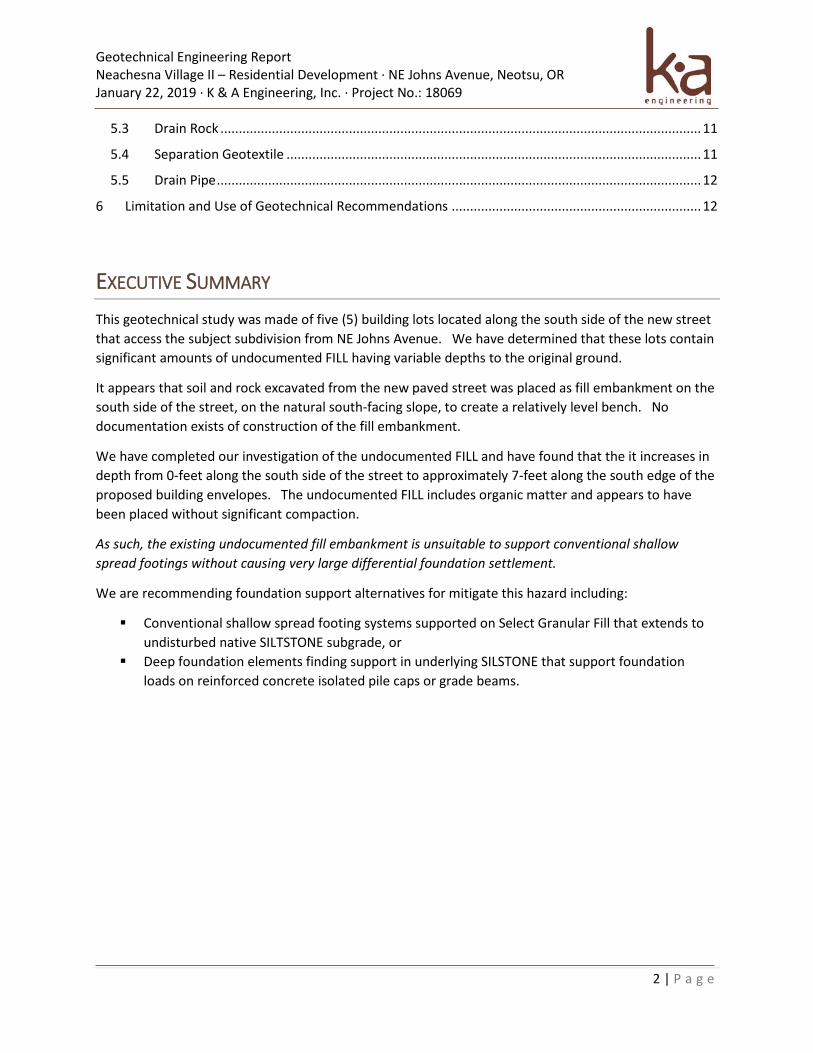
EXECUTIVE SUMMARY This geotechnical study was made of five (5) building lots located along the south side of the new street that access the subject subdivision from NE Johns Avenue. We have determined that these lots contain significant amounts of undocumented FILL having variable depths to the original ground.
It appears that soil and rock excavated from the new paved street was placed as fill embankment on the south side of the street, on the natural south-facing slope, to create a relatively level bench. No documentation exists of construction of the fill embankment.
We have completed our investigation of the undocumented FILL and have found that the it increases in depth from 0-feet along the south side of the street to approximately 7-feet along the south edge of the proposed building envelopes. The undocumented FILL includes organic matter and appears to have been placed without significant compaction.
As such, the existing undocumented fill embankment is unsuitable to support conventional shallow spread footings without causing very large differential foundation settlement.
We are recommending foundation support alternatives for mitigate this hazard including:
Conventional shallow spread footing systems supported on Select Granular Fill that extends to undisturbed native SILTSTONE subgrade, or
Deep foundation elements finding support in underlying SILSTONE that support foundation loads on reinforced concrete isolated pile caps or grade beams.

Geotechnical Engineering Report Neachesna Village II – Residential Development · NE Johns Avenue, Neotsu, OR January 22, 2019 · K & A Engineering, Inc. · Project No.: 18069
3 | P a g e
1 INTRODUCTION At your request, we have made a preliminary geotechnical investigation for the purposes of:
Characterizing the depth, nature, and extent of undocumented FILL on the site, Evaluating the suitability of the undocumented FILL to support conventional shallow spread
footing systems, Developing seismic design criteria, and Providing alternatives for constructing systems to provide adequate foundation support.
The scope of our services included:
Fieldwork including Four (4) probes, and One (1) continuous-sample boring
Laboratory analysis of boring samples, Analysis of field data, Foundation system economic analysis, and This preliminary Geotechnical Engineering Report.
Our services meet the requirements of the 2014 Oregon Structural Specialty Code, Section 1803 - Geotechnical Investigations.
2 PROJECT SITE DESCRIPTION
2.1 SITE LOCATION The project site is located in the unincorporated community of Neotsu, northeast of Lincoln City, on NE Johns Avenue, which can be accessed from U.S. 101, 1,000-ft north of the project site. Nearby bodies of water include Devils Lake, a short distance southeast and southwest of the site (less than 2,000-ft either way), the Pacific Ocean, 1.2-miles west, and Devil River, 0.6-mile northeast.
See the project Vicinity Map in Appendix A of this report.
2.2 SURFACE CONDITIONS The project site is located on the south side of a small ridge that separates U.S. 101 to the north and NE Johns Avenue.
Construction of the new local street accessing the subdivision from NE Johns Avenue involved what appears to be a full-bench cut into the south-facing hillside. Materials excavated from the cut were placed south of the street on the hillside. This undocumented FILL extends to the south edge of the envelopes for five (5) duplex buildings planned for the site. The south edge of this undocumented FILL terminates in a fill slope having a gradient of approximately 2H : 1V.
Geotechnical Engineering Report Neachesna Village II – Residential Development · NE Johns Avenue, Neotsu, OR January 22, 2019 · K & A Engineering, Inc. · Project No.: 18069
4 | P a g e
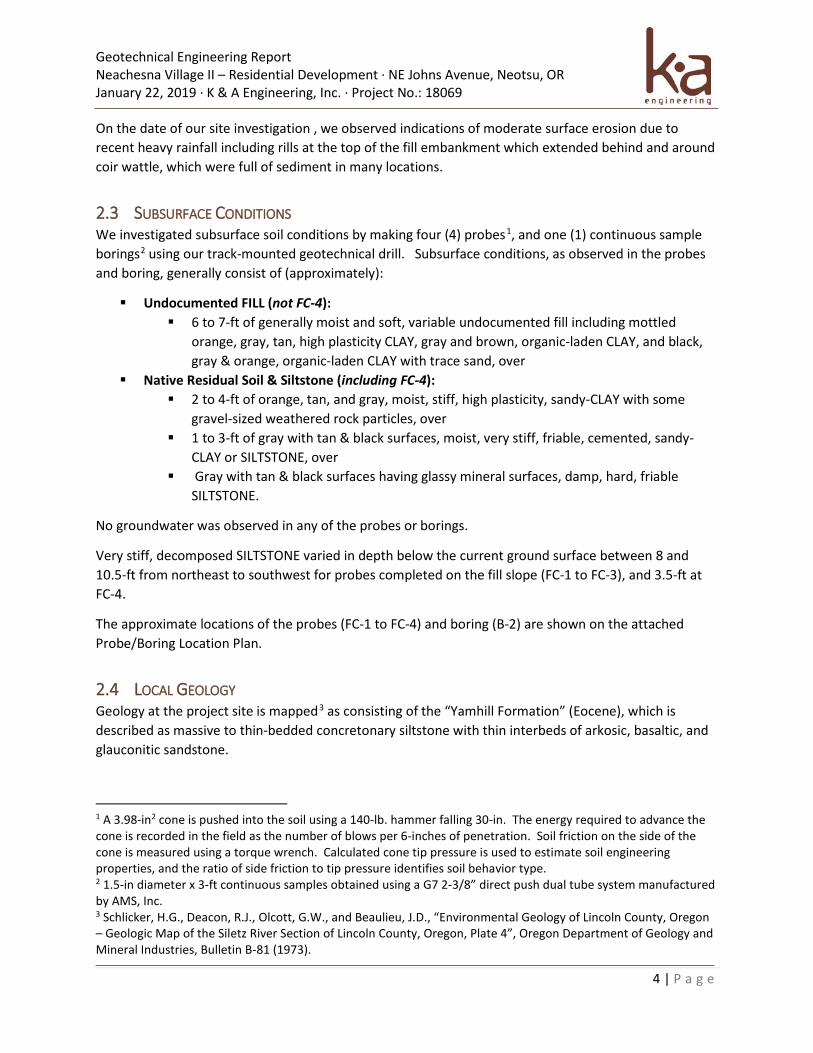
On the date of our site investigation , we observed indications of moderate surface erosion due to recent heavy rainfall including rills at the top of the fill embankment which extended behind and around coir wattle, which were full of sediment in many locations.
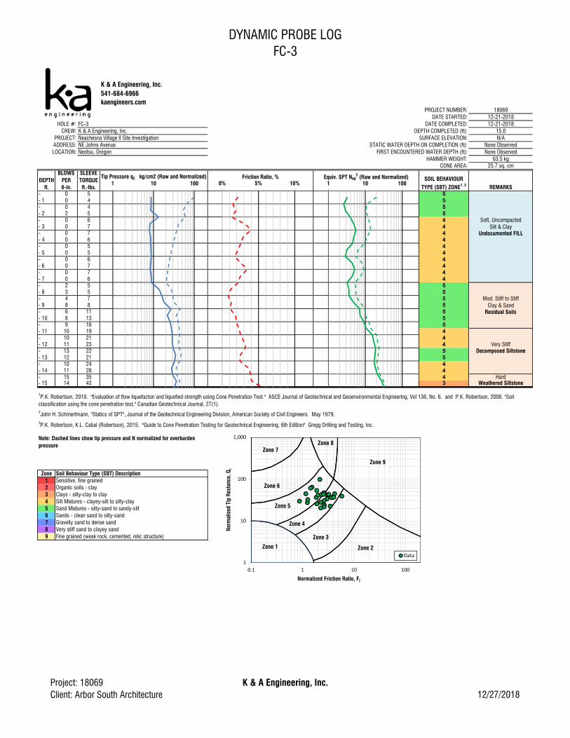
2.3 SUBSURFACE CONDITIONS We investigated subsurface soil conditions by making four (4) probes1, and one (1) continuous sample borings2 using our track-mounted geotechnical drill. Subsurface conditions, as observed in the probes and boring, generally consist of (approximately):
Undocumented FILL (not FC-4): 6 to 7-ft of generally moist and soft, variable undocumented fill including mottled
orange, gray, tan, high plasticity CLAY, gray and brown, organic-laden CLAY, and black, gray & orange, organic-laden CLAY with trace sand, over
Native Residual Soil & Siltstone (including FC-4): 2 to 4-ft of orange, tan, and gray, moist, stiff, high plasticity, sandy-CLAY with some
gravel-sized weathered rock particles, over 1 to 3-ft of gray with tan & black surfaces, moist, very stiff, friable, cemented, sandy-
CLAY or SILTSTONE, over Gray with tan & black surfaces having glassy mineral surfaces, damp, hard, friable
SILTSTONE.
No groundwater was observed in any of the probes or borings.
Very stiff, decomposed SILTSTONE varied in depth below the current ground surface between 8 and 10.5-ft from northeast to southwest for probes completed on the fill slope (FC-1 to FC-3), and 3.5-ft at FC-4.
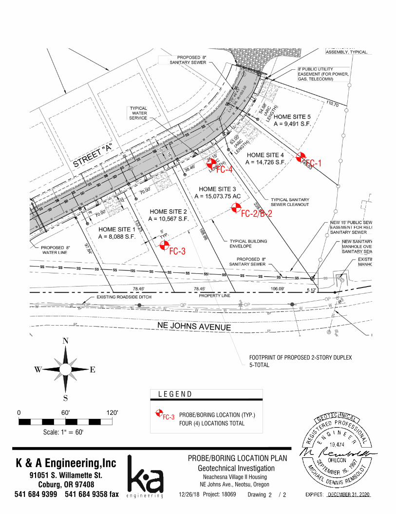
The approximate locations of the probes (FC-1 to FC-4) and boring (B-2) are shown on the attached Probe/Boring Location Plan.
2.4 LOCAL GEOLOGY Geology at the project site is mapped3 as consisting of the “Yamhill Formation” (Eocene), which is described as massive to thin-bedded concretonary siltstone with thin interbeds of arkosic, basaltic, and glauconitic sandstone.
1 A 3.98-in2 cone is pushed into the soil using a 140-lb. hammer falling 30-in. The energy required to advance the cone is recorded in the field as the number of blows per 6-inches of penetration. Soil friction on the side of the cone is measured using a torque wrench. Calculated cone tip pressure is used to estimate soil engineering properties, and the ratio of side friction to tip pressure identifies soil behavior type. 2 1.5-in diameter x 3-ft continuous samples obtained using a G7 2-3/8” direct push dual tube system manufactured by AMS, Inc. 3 Schlicker, H.G., Deacon, R.J., Olcott, G.W., and Beaulieu, J.D., “Environmental Geology of Lincoln County, Oregon – Geologic Map of the Siletz River Section of Lincoln County, Oregon, Plate 4”, Oregon Department of Geology and Mineral Industries, Bulletin B-81 (1973).
Geotechnical Engineering Report Neachesna Village II – Residential Development · NE Johns Avenue, Neotsu, OR January 22, 2019 · K & A Engineering, Inc. · Project No.: 18069
5 | P a g e
In our opinion, the observed gray, tan & red, hard, weathered siltstone is consistent with the described geology.
3 GEOLOGIC HAZARDS
3.1 DESIGN EARTHQUAKE Based on the observed subsurface conditions and criteria in ASCE 7-10, if the proposed buildings are supported directly on bedrock, the site class may be appropriately designated as Site Class “D.”
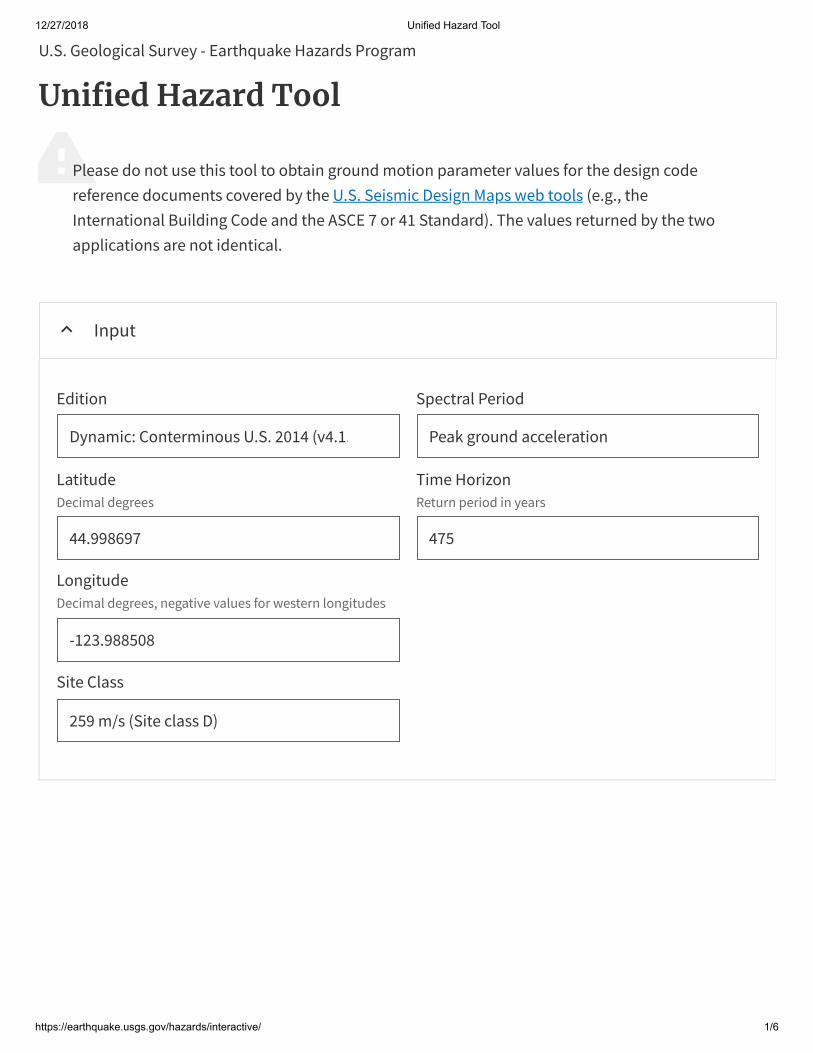
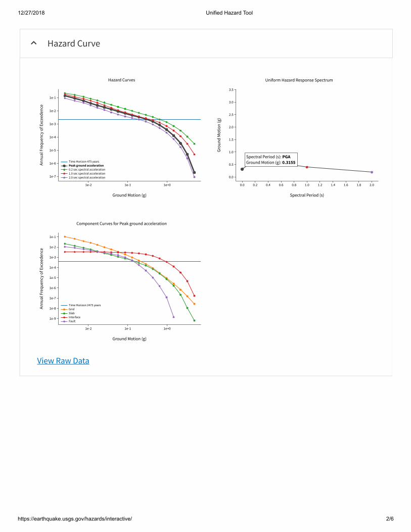
The design earthquake was determined using criteria including an event having a 10-percent chance, or higher, of occurring within a 50-year period, and soil site class D. Based on analysis using current modeling of local sources of earthquake ground motion (crustal, deep, and subduction zone)4, the design earthquake is a Cascadia Megathrust event with a magnitude between 8.5 to 9.0 and peak ground acceleration of 0.32g.
3.2 FAULTING AND LATERAL SPREADING Table 1 summarizes nearby mapped active faults5, 6, 7 within a 50-mile radius of the project site. A few seismic events (M > 4.0) have occurred within 50-miles of the project site8, 9, 10. These events are summarized in Table 2 below.
The nearest mapped active faults are the Siletz Bay Faults, a collection of reverse and lateral faults over 5-miles S-SW, beginning at the mouth of Siletz Bay.
As there are no active faults mapped through or in the near vicinity of the project site, there is not a significant hazard of ground rupture due to faulting.
Many of the seismic events listed in Table 2 are associated with offshore fault zones related to the Cascadia Subduction Zone, indicating the active nature of this area. The Cascadia Subduction Fault Zone is the largest contributor to seismic hazard. See the deaggregation summary for this project site, Appendix C.
4 2014 USGS dynamic conterminous PSHA, online at the USGS Earthquake Hazards Program: https://earthquake.usgs.gov/hazards/interactive/ 5 Active defined as having ruptured within the current geologic age (Quaternary – 1.5Ma). 6 Personius, S.F., Dark, R.L., Bradley, L.A., and Haller, K.M., “Map of Quaternary Faults and Folds in Oregon”, U.S. Geologic Survey, OFR-03-095 (2003). 7 U.S. Geological Survey, 2006, Quaternary fault and fold database for the United States, accessed May 9, 2018, from USGS web site: http//earthquake.usgs.gov/hazards/qfaults. 8 University of Washington (1963): Pacific Northwest Seismic Network. International Federation of Digital Seismograph Networks. Other/Seismic Network. 10.7914/SN/UW 9 Johnson, A.G., Schofield, D.H., and Madin, I.P., “Earthquake Database for Oregon, 1833 through October 25, 1993”, Oregon Department of Geology and Mineral Industries, OFR 94-04 (1994). 10 NCEDC (2016), Northern California Earthquake Data Center. UC Berkeley Seismological Laboratory. Dataset. doi:10.7932/NCEDC

Geotechnical Engineering Report Neachesna Village II – Residential Development · NE Johns Avenue, Neotsu, OR January 22, 2019 · K & A Engineering, Inc. · Project No.: 18069
6 | P a g e
Table 1. Nearby Quaternary Faults.
Fault Name Fault ID Length (km)
Slip Rate (mm/yr) Type11
Distance12 and Direction
from Site (miles)
Paci
fic B
orde
r Phy
siog
raph
ic Z
one
Gales Creek Fault Zone 718 73 < 0.2 RL, R 49 NE Salem-Eola Hills Homocline 719 32 < 0.2 H 41 E Cascadia Fold and Fault Belt 784 484 1.0 - 5.0 T 7 W-NW
Unnamed Offshore Faults 785 280 1.0 - 5.0 LL, RL, N, R 14 NW Stonewall anticline 786 70 1.0 - 5.0 A 21 W
Nehalem Bank Fault 789 101 1.0 - 5.0 RL, R 31 N Fault G 791 57 > 5.0 LL, N 42 N-NW
Daisy Bank Fault 798 80 > 5.0 LL 42 SW Wecoma Fault 799 96 > 5.0 LL 28 W
Corvallis Fault Zone 869 40 < 0.2 T, LL 43 SE Owl Creek Fault 870 15 < 0.2 R 48 SE
Turner and Mill Creek Faults 871 18 < 0.2 U, LL 48 E-SE Waldo Hills Fault 872 12 < 0.2 N 48 E-SE
Tillamook Bay Fault Zone 881 32 < 0.2 R, LL 34 N-NE Happy Camp Fault 882 3 < 0.2 T 31 N
Siletz Bay Faults 883 10 < 0.2 N 5 S-SW Cape Foulweather Fault 884 10 < 0.2 R, LL 12 S
Yaquina Faults 885 13 0.2 - 1.0 R, LL 22 S Waldport Faults 886 14 < 0.2 R, LL, N 37 S
Table 2. Nearby seismic events with M > 4.0.
Date Time13 Latitude Longitude Magnitude Nearby Fault(s)
March 7, 1963 23:53:25.00 44.9000 -123.5000 4.60 N/A August 19, 2004 06:06:03.63 44.6647 -124.3003 4.70 784, 786 August 21, 1959 00:28:17.00 44.8000 -124.6830 4.60 786, 797, 798, 799
July 23, 1959 08:15:12.00 44.5000 -124.5000 4.30 785, 786
Due to absence of loose, saturated sands, there is not a significant hazard of lateral spreading at the project site.
11 Types of Faults: T = thrust, LL = left lateral (strike-slip), RL = right lateral (strike slip), N = normal, R = reverse, A = anticline, H = homocline. 12 Distance was measured from the site to the (approximate) closest location along the fault or collection of faults. 13 Time expressed in coordinated universal time (8-hrs ahead of PTS, 7-hrs ahead of PDT).
Geotechnical Engineering Report Neachesna Village II – Residential Development · NE Johns Avenue, Neotsu, OR January 22, 2019 · K & A Engineering, Inc. · Project No.: 18069
7 | P a g e
3.3 EXPANSIVE SOILS The undocumented FILL, high plasticity organic and non-organic CLAY found near the ground surface of the project site present a high hazard of soil expansion.
This hazard can be mitigated by locating foundation support at a sufficient depth below the ground surface to ensure relatively constant water content throughout the year. Laboratory analysis of the samples obtained from the site suggest that this depth is 3-feet below the existing ground surface.
3.4 FOUNDATION SETTLEMENT The undocumented FILL presents a high hazard of total and differential settlement for conventional shallow spread footings.
Based on our observations from probing, the undocumented FILL appears to consist of native organic and non-organic CLAY and siltstone mixed with surface organics. Based on the very low cone tip resistance (less than 10-kg/cm2), the undocumented fill has likely received no compaction and was placed immediately after excavation.
Foundations placed on undocumented fill will have experience severe differential settlement exceeding typical requirements for angular distortion (𝜃𝜃𝑎𝑎 is generally between 1/500 and 1/250), resulting in deficiencies that may present a structural hazard.
We have made our preliminary recommendations for foundations to mitigate this hazard.
3.5 LIQUEFACTION Due to the absence of loose, saturated SAND, there is a low hazard of liquefaction at the project site.
4 RECOMMENDATIONS FOR DESIGN AND CONSTRUCTION
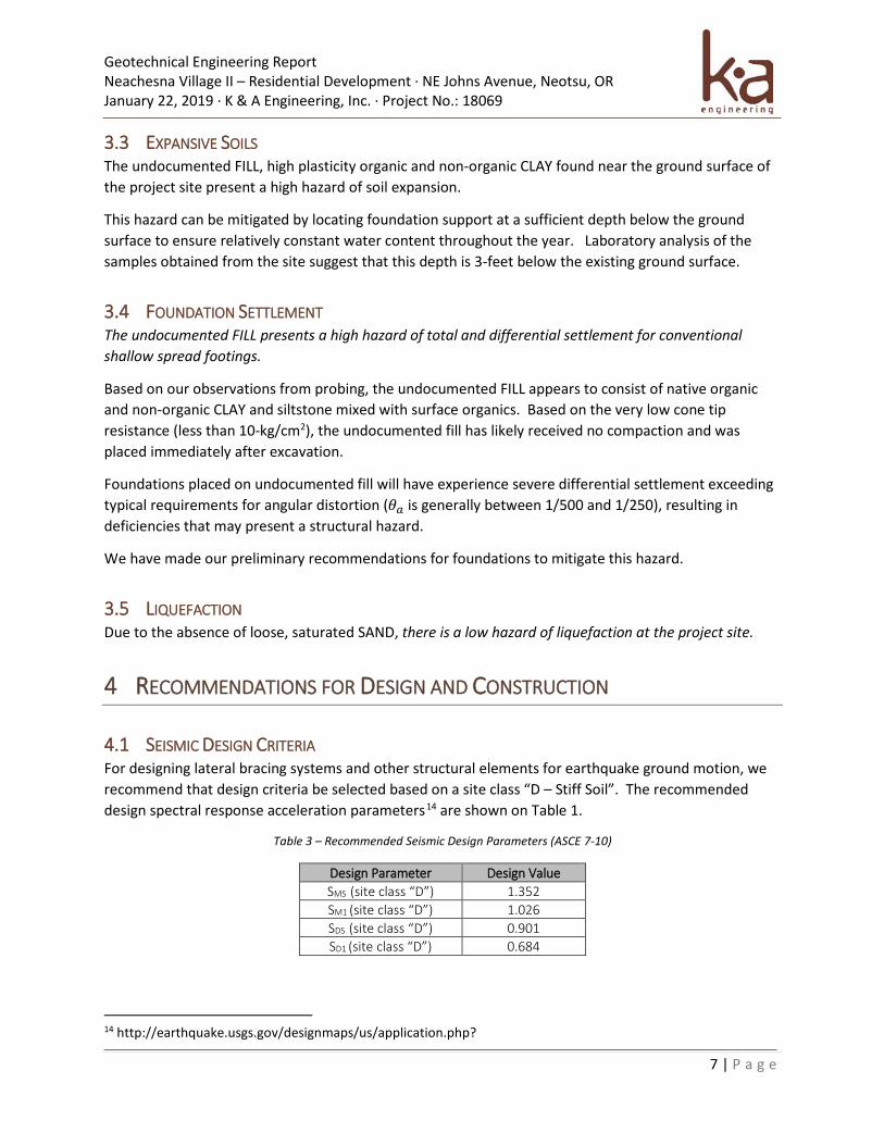
4.1 SEISMIC DESIGN CRITERIA For designing lateral bracing systems and other structural elements for earthquake ground motion, we recommend that design criteria be selected based on a site class “D – Stiff Soil”. The recommended design spectral response acceleration parameters14 are shown on Table 1.
Table 3 – Recommended Seismic Design Parameters (ASCE 7-10)
Design Parameter Design Value SMS (site class “D”) 1.352 SM1 (site class “D”) 1.026 SDS (site class “D”) 0.901 SD1 (site class “D”) 0.684
14 http://earthquake.usgs.gov/designmaps/us/application.php?
Geotechnical Engineering Report Neachesna Village II – Residential Development · NE Johns Avenue, Neotsu, OR January 22, 2019 · K & A Engineering, Inc. · Project No.: 18069
8 | P a g e
For design of “non-structural” elements and anchorages for lateral earthquake loads, we recommend a design peak ground acceleration of 0.32g (10% chance of exceedance in 50-years).
4.2 FOUNDATION SUPPORT
4.2.1 General Discussion Due to the compressibility and low bearing capacity of the undocumented FILL found on the study area, we do not recommend that permanent foundations consist of conventional shallow spread footing systems bearing on undocumented FILL.
We recommend that foundation loads be supported either directly on underlying SILTSTONE or on Select Granular Fill that extends to SILTSTONE. Suitable foundation systems may consist of either:
Shallow spread footings supported directly on SILTSTONE or on Select Granular Fill that extends to SILTSTONE, or
Deep foundation elements that find support in underlying native SILTSTONE.
4.2.2 Conventional Shallow Spread Footings Conventional shallow spread footings may support permanent foundation loads if constructed to bear either directly on:
Native, undisturbed weathered or decomposed stiff SILTSTONE, or Select Granular Fill that extends to undisturbed weathered or decomposed stiff SILTSTONE.
This foundation system requires excavation and removal of all undocumented FILL, creating the foundation subgrade on native, undisturbed weathered or decomposed stiff SILTSTONE (benched to accommodate the natural slope), and placement of Select Granular Fill to the desired footing grade.
Additionally, the foundation pad must be drained by the placement of a permanent perimeter footing drain consisting of:
3-inch minimum diameter perforated Drain Pipe, placed with the holes facing downward on the subgrade, covered by
12-inches (minimum) of Drain Rock placed around the sides and top of the perforated Drain Pipe, enveloped by
Separation Geotextile.
The drain shall be placed on the subgrade, around the entire perimeter of the excavation, and connected to a solid Drain Pipe that routes water away from the foundation to daylight or an approved storm drain system. In no event shall roof drains be connected to the foundation drain system.
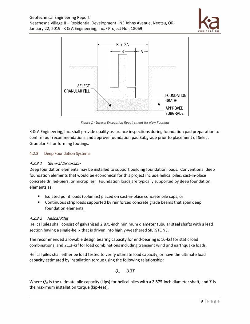
The excavation to remove undocumented FILL to approved foundation pad subgrade shall extend, laterally, from the perimeter foundation to accommodate the minimum distance shown on Figure 1.
Geotechnical Engineering Report Neachesna Village II – Residential Development · NE Johns Avenue, Neotsu, OR January 22, 2019 · K & A Engineering, Inc. · Project No.: 18069
9 | P a g e
Figure 1 - Lateral Excavation Requirement for New Footings
K & A Engineering, Inc. shall provide quality assurance inspections during foundation pad preparation to confirm our recommendations and approve foundation pad Subgrade prior to placement of Select Granular Fill or forming footings.
4.2.3 Deep Foundation Systems
4.2.3.1 General Discussion Deep foundation elements may be installed to support building foundation loads. Conventional deep foundation elements that would be economical for this project include helical piles, cast-in-place concrete drilled-piers, or micropiles. Foundation loads are typically supported by deep foundation elements as:
Isolated point loads (columns) placed on cast-in-place concrete pile caps, or Continuous strip loads supported by reinforced concrete grade beams that span deep
foundation elements.
4.2.3.2 Helical Piles Helical piles shall consist of galvanized 2.875-inch minimum diameter tubular steel shafts with a lead section having a single-helix that is driven into highly-weathered SILTSTONE.
The recommended allowable design bearing capacity for end-bearing is 16-ksf for static load combinations, and 21.3-ksf for load combinations including transient wind and earthquake loads.
Helical piles shall either be load tested to verify ultimate load capacity, or have the ultimate load capacity estimated by installation torque using the following relationship:
𝑄𝑄𝑢𝑢 = 8.3𝑇𝑇 Where 𝑄𝑄𝑢𝑢 is the ultimate pile capacity (kips) for helical piles with a 2.875-inch diameter shaft, and 𝑇𝑇 is the maximum installation torque (kip-feet).
Geotechnical Engineering Report Neachesna Village II – Residential Development · NE Johns Avenue, Neotsu, OR January 22, 2019 · K & A Engineering, Inc. · Project No.: 18069
10 | P a g e
The installer should provide K & A Engineering, Inc. with a copy of the pile load test versus installation pressure/torque relationship certified by the pile manufacturer. Additionally, the manufacturer’s literature that documents the material and dimensions of piles used should be provided to the engineer prior to installation, for approval. K & A Engineering, Inc. must approve of all proposed piles, driving equipment, and pressure-torque relationships prior to pile installation. K & A Engineering, Inc. should inspect and approve of all and helical piles installed.
4.2.3.3 Drilled Piers Drilled piers should be designed for end-bearing only in undisturbed weathered SILTSTONE with a minimum of 1-foot embedment in decomposed/weathered SILTSTONE. The maximum allowable design end-bearing pressure is 16-ksf for static load combinations, and 21.3-ksf for load combinations including transient wind and earthquake loads.
All loose soils shall be removed from the bottom of the pre-drilled pier hole prior to placement of reinforcing bar or concrete.
Concrete shall be placed in the pre-drilled hole from the bottom up using either a tremie or concrete pump hose. In no event, shall concrete be dropped into the hole.
If water is present in the hole, water shall either be removed prior to placement of concrete, or the concrete shall be placed with thee tremie or pump hose below the water surface, so that water is gradually displaced during concrete placement.
4.2.3.4 Micropiles For ease of installation we recommend that micropiles consists of a hollow-bar system grouted into the soil using a neat-cement grout. Micropiles shall find load bearing in the underlying native weathered SILTSONE located approximately 7-feet or deeper below the existing ground surface (at the south edge of the undocumented FILL).
The top 5-feet of all micropiles shall be cased with 4-inch x 0.25-inch wall steel pipe to minimize buckling.
For preliminary design purposes, we recommend a maximum allowable grout bond strength of 4-ksf in weathered SILSTONE.
A minimum of one load test is required prior to installing production piles. The load test shall include:
Ultimate load, in tension, to a minimum 200-percent of the maximum specified working load. The load test shall be made in increments of 10, 25, 50, 100, 150, and 200-percent of maximum specified working load.
Creep Testing. A creep test shall be made a 133-percent of the maximum specified working load. Criteria for successful creep is less than 2-mm of creep over one log-cycle of time.
K & A Engineering, Inc. shall inspect load testing and verify ultimate load at failure or that no failure occurred. Based on the load test results, K & A Engineering, Inc. shall verify the validity of the
Geotechnical Engineering Report Neachesna Village II – Residential Development · NE Johns Avenue, Neotsu, OR January 22, 2019 · K & A Engineering, Inc. · Project No.: 18069
11 | P a g e
preliminary allowable grout bond strength and make recommendations for embedment lengths of the production piles, accordingly.
K & A Engineering, Inc. must approve of all proposed micropile materials, installation equipment, and load testing equipment, prior to pile installation. K & A Engineering, Inc. should inspect and approve of all and micropiles installed.
5 SPECIFICATIONS
5.1 SUBGRADE Approved Subgrade shall consist of decomposed or weathered SILTSTONE.
All Subgrades shall be inspected and approved by K & A Engineering, Inc. prior to placement of fills or foundations.
5.2 SELECT GRANULAR FILL
5.2.1 General Requirements Select granular fill may consist entirely of fine select granular fill or a minimum of 9-inches of coarse select granular fill covered with a minimum of 3-inches of fine select granular fill.
5.2.2 Coarse Select Granular Fill Coarse select granular fill shall consist of clean, well-graded quarry stone having a maximum particle size of 5-inches. Quarry stone should be durable and have 100-percent fractured faces.
5.2.3 Fine Select Granular Fill Fine select granular fill should consist of clean, durable, well-graded material with a maximum particle size of 3/4-inches and a maximum of 10-percent passing the no. 200 sieve. Select granular fill shall be placed in layers not to exceed 12-inches (loose) and mechanically compacted to a dry density exceeding 95-percent of maximum as determined by ASTM D698 (Std. Proctor).
5.3 DRAIN ROCK Drain rock should consist of clean, durable, 1 ½-inch (maximum), open-graded, angular crushed quarry stone. The rock should be placed over and to the side of the perforated pipe so that the pipe has a minimum of 12-inches of cover. The drain rock should be wrapped with separation geotextile.
5.4 SEPARATION GEOTEXTILE Separation geotextile shall be placed on the grade and around the perimeter of the trench prior to placement of the perforated pipe. After the pipe is laid and drain rock placed, the geotextile shall completely wrap around the drain rock.

Geotechnical Engineering Report Neachesna Village II – Residential Development · NE Johns Avenue, Neotsu, OR January 22, 2019 · K & A Engineering, Inc. · Project No.: 18069
12 | P a g e
Separation geotextile shall consist of a polypropylene non-woven needle—punched fabric that is stabilized against degradation from ultraviolet light exposure (sunlight).
Table 1. Separation geotextile specifications.
Property Test Method Specification
Tear Strength ASTM D4533 > 30 lb.
Puncture Strength ASTM D4833 > 40 lb.
Permittivity ASTM D4491 > .02 sec-1
Apparent Opening Size (AOS)
ASTM D4571 < No. 70 (US sieve)
Ultraviolet Stability ASTM D4355 > 50% ret. After 500 hours exposure
5.5 DRAIN PIPE Perforated Drainpipe shall consist of schedule 40 PVC or an equivalent rigid pipe drilled with ½-inch holes spaced at 6-inches (staggered) perforated pipe. Perforations should face down.
6 LIMITATION AND USE OF GEOTECHNICAL RECOMMENDATIONS This report has been prepared for the exclusive use of Arbor South Architecture for the subject project.
This geotechnical investigation, analysis, and recommendations meet the standards of care of competent geotechnical engineers providing similar services at the time these services were provided.
We do not warrant or guarantee site surface subsurface conditions. Exploration test holes indicate soil conditions only at specific locations (i.e. the test hole locations) to the depths penetrated. They do not necessarily reflect soil/rock materials or groundwater conditions that exist between or beyond exploration locations or limits.
The scope of our services does not include construction safety precautions, techniques, sequences, or procedures, except as specifically recommended in this report. Our services should not be interpreted as an environmental assessment of site conditions.
K & A Engineering, Inc. 541·684·9399 · Kaengineers.com Established 1998
Appendix A
Maps Vicinity Map
Probe Location Plan
Geotechnical Engineering Report Neachesna Village II – Residential Development
NE Johns Avenue, Neotsu, Oregon Project: 18069
January 22, 2019
Prepared for: Arbor South Architecture
380 Lincoln Street Eugene, OR 97401
Prepared by: Michael Remboldt, P.E., G.E.
K & A Engineering, Inc. Coburg, Oregon

541 684 9399 541 684 9358 faxCoburg, OR 97408
91051 S. Willamette St.K & A Engineering,Inc
0 2000' 4000'
/Project: Drawing
VICINITY MAPGeotechnical Investigation
Neachesna Village II Housing NE Johns Ave., Neotsu, Oregon
12/26/18 18069 1 2
Scale: 1" = 2000'
FOOTPRINT OF PROPOSED 2-STORY DUPLEX5-TOTAL
N
S
W E DEVILS LAKE
HIGHWAY 101 (U.S. 101)
FC-3
FC-1
FC-2/B-2
FC-4
FC-3
541 684 9399 541 684 9358 faxCoburg, OR 97408
91051 S. Willamette St.K & A Engineering,Inc
N
S
W E
0 60' 120'
/Project: Drawing
PROBE/BORING LOCATION PLANGeotechnical Investigation
Neachesna Village II Housing NE Johns Ave., Neotsu, Oregon
12/26/18 18069 2 2
Scale: 1" = 60'
PROBE/BORING LOCATION (TYP.)
L E G E N D
FOOTPRINT OF PROPOSED 2-STORY DUPLEX5-TOTAL
FOUR (4) LOCATIONS TOTAL
K & A Engineering, Inc. 541·684·9399 · Kaengineers.com Established 1998
Appendix B
Probes and Borings Probe Logs Boring Logs
Geotechnical Engineering Report Neachesna Village II – Residential Development
NE Johns Avenue, Neotsu, Oregon Project: 18069
January 22, 2019
Prepared for: Arbor South Architecture
380 Lincoln Street Eugene, OR 97401
Prepared by: Michael Remboldt, P.E., G.E.
K & A Engineering, Inc. Coburg, Oregon
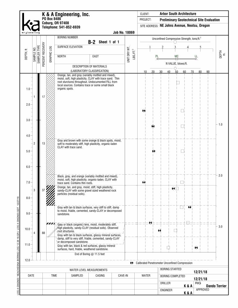
Orange, tan, and gray (variably mottled and mixed),moist, soft, high plasticity, CLAY with trace sand. Thinroot sturctures throughout. Undocumented FILL fromlocal sources. Contains trace or some small blackorganic spots.
Gray and brown with some orange & black spots, moist,soft to moderately stiff, high plasticity, organic-ladenCLAY with trace sand.
Black, gray, and orange (variably mottled and mixed),moist, soft, high plasticity, organic-laden, CLAY withtrace sand. Contains thin roots.Orange, tan, and gray, moist, stiff, high plasticity,sandy-CLAY with some gravel sized weathered rockparticles (residual soils).
Gray with tan & black surfaces, very stiff to stiff, dampto moist, friable, cemented, sandy-CLAY or decomposedsandstone.
Gray or black (organic) lens, moist, moderately stiff,high plasticity, sandy-CLAY (residual soils). Observedroot structures.Gray with tan & black surfaces, glassy mineral surfaces,damp, stiff to very stiff, friable, cemented, sandy-CLAYor decomposed sandstone.Gray with tan, black & red surfaces, glassy mineralsurfaces, hard, friable, weathered sandstone.
End of Boring @ 11.5 feet
Dando TerrierAPPROVED
K & AENGINEER
WATER LEVEL MEASUREMENTS
SAMPLED CASING
BORING STARTED
DRILLER
DATE12/21/18
12/21/18
K & A
TIME
RIG
SITE ADDRESS:
B-2BORING NUMBER
EAST
SAM
PLER
TYP
ESheet 1 of 1
Arbor South Architecture
DEPT
Hm
.
1.0
2.0
3.0
N VALUE, blows/ft.
10 20 30 40 50 60 70 80 90
PL LLMC
DEPT
H, ft
1.0
2.0
3.0
4.0
5.0
6.0
7.0
8.0
9.0
10.0
11.0
12.0
NORTH
GRAP
HIC
LOG
Calibrated Penetrometer Unconfined Compression
1 2 3 4 5
Preliminary Geotechnical Site Evaluation
NE Johns Avenue, Neotsu, Oregon
Unconfined Compressive Strength, tons/ft.2
DESCRIPTION OF MATERIALS
(LABORATORY CLASSIFICATION)
UNIT
DRY
WT.
LBS.
/FT.
3
SAM
PLE
NO.
PERC
ENT
RECO
VERY
K & A Engineering, Inc.PO Box 8486Coburg, OR 97408Telephone: 541-852-6939
LOG
A G
NG
N03
NE
AC
HE
SN
A B
OR
ING
LO
G 1
2 26
18.
GP
J L
OG
A G
NG
N03
.GD
T 1
2/27
/18
1
2
3
4
17
13
37
88
BORING COMPLETEDCAVE-IN WATER
SURFACE ELEVATION
CLIENT:
PROJECT:
Job No. 18069
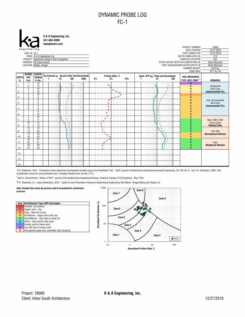
DYNAMIC PROBE LOGFC-1
K & A Engineering, Inc. 541-684-6966kaengineers.com
PROJECT NUMBER: 18069DATE STARTED: 12-21-2018
HOLE #: FC-1 DATE COMPLETED: 12-21-2018CREW: K & A Engineering, Inc. DEPTH COMPLETED (ft): 12.0
PROJECT: Neachesna Village II Site Investigation SURFACE ELEVATION: N/AADDRESS: NE Johns Avenue STATIC WATER DEPTH ON COMPLETION (ft): None ObservedLOCATION: Neotsu, Oregon FIRST ENCOUNTERED WATER DEPTH (ft): None Observed
HAMMER WEIGHT: 63.5 kgCONE AREA: 25.7 sq. cm
DEPTHBLOWS
PERSLEEVETORQUE
Tip Pressure qC kg/cm2 (Raw and Normalized) Friction Ratio, % Equiv. SPT N602 (Raw and Normalized)
ft. 6-in. ft.-lbs.- 1 10 8- 1 2 13 9 Compacted- 2 15 9 Silt & Clay- 2 1 16 9 Undocumented FILL- 0 12 3- 3 0 8 4- 0 8 4 Soft, Uncompacted- 4 0 8 4 Silt & Clay- 0 8 4 Undocumented FILL- 5 0 8 4- 1 9 4- 6 1 10 4- 2 10 4- 7 4 11 5 Mod. Stiff to Stiff- 10 13 5 Clay & Sand- 8 9 15 5 Residual Soils- 13 19 5- 9 14 24 5 Very Stiff- 14 33 4 Decomposed Siltstone- 10 16 42 4- 20 37 5- 11 23 31 5 Hard- 23 30 5 Weathered Siltstone- 12 22 28 5-- 13-- 14-- 15
Zone Soil Behaviour Type (SBT) Description1 Sensitive, fine grained2 Organic soils - clay3 Clays - silty-clay to clay4 Silt Mixtures - clayey-silt to silty-clay5 Sand Mixtures - silty-sand to sandy-silt6 Sands - clean sand to silty-sand7 Gravelly sand to dense sand8 Very stiff sand to clayey sand 9 Fine grained (weak rock, cemented, relic structure)
Note: Dashed lines show tip pressure and N normalized for overburden pressure
SOIL BEHAVIOUR TYPE (SBT) ZONE1, 3
1P.K. Robertson, 2010. "Evaluation of flow liquefacton and liquefied strength using Cone Penetration Test." ASCE Journal of Geotechnical and Geoenvironmental Engineering, Vol 136, No. 6. and P.K. Robertson, 2000. "Soil classification using the cone penetration test," Canadian Geotechnical Journal, 27(1).2John H. Schmertmann, "Statics of SPT", Journal of the Geotechnical Engineering Division, American Society of Civil Engineers. May 1979.3P.K. Robertson, K.L. Cabal (Robertson), 2015. "Guide to Cone Penetration Testing for Geotechnical Engineering, 6th Edition" Gregg Drilling and Testing, Inc.
REMARKS0% 5% 10%1 10 100 1000 1 10 100
1
10
100
1,000
0.1 1 10 100
Norm
aliz
ed T
ip R
esta
nce,
Qt
Normalized Friction Ratio, Ft
Data
Zone 7
Zone 6
Zone 5
Zone 4
Zone 3
Zone 2
Zone 8
Zone 1
Zone 9
Project: 18069Client: Arbor South Architecture
K & A Engineering, Inc.12/27/2018

DYNAMIC PROBE LOGFC-2
K & A Engineering, Inc. 541-684-6966kaengineers.com
PROJECT NUMBER: 18069DATE STARTED: 12-21-2018
HOLE #: FC-2 DATE COMPLETED: 12-21-2018CREW: K & A Engineering, Inc. DEPTH COMPLETED (ft): 12.0
PROJECT: Neachesna Village II Site Investigation SURFACE ELEVATION: N/AADDRESS: NE Johns Avenue STATIC WATER DEPTH ON COMPLETION (ft): None ObservedLOCATION: Neotsu, Oregon FIRST ENCOUNTERED WATER DEPTH (ft): None Observed
HAMMER WEIGHT: 63.5 kgCONE AREA: 25.7 sq. cm
DEPTHBLOWS
PERSLEEVETORQUE
Tip Pressure qC kg/cm2 (Raw and Normalized) Friction Ratio, % Equiv. SPT N602 (Raw and Normalized)
ft. 6-in. ft.-lbs.- 0 7 5- 1 0 7 4- 0 8 4 Moderately Stiff- 2 0 10 4 Silt & Clay- 0 12 3 Undocumented FILL- 3 2 15 4- 0 11 3- 4 0 7 4- 0 4 5- 5 0 4 5 Soft- 0 4 5 Silt & Clay- 6 0 4 5 Undocumented FILL- 0 4 5- 7 0 4 5- 3 6 5 Mod. Stiff to Stiff- 8 3 8 4 Clay & Sand- 3 10 4 Residual Soil- 9 7 12 5- 13 19 5 Very Stiff- 10 12 26 4 Decomposed Siltstone- 21 39 5- 11 24 53 4 Hard- 22 48 4 Weathered Siltstone- 12 21 44 4-- 13-- 14-- 15
Zone Soil Behaviour Type (SBT) Description1 Sensitive, fine grained2 Organic soils - clay3 Clays - silty-clay to clay4 Silt Mixtures - clayey-silt to silty-clay5 Sand Mixtures - silty-sand to sandy-silt6 Sands - clean sand to silty-sand7 Gravelly sand to dense sand8 Very stiff sand to clayey sand 9 Fine grained (weak rock, cemented, relic structure)
Note: Dashed lines show tip pressure and N normalized for overburden pressure
SOIL BEHAVIOUR TYPE (SBT) ZONE1, 3
1P.K. Robertson, 2010. "Evaluation of flow liquefacton and liquefied strength using Cone Penetration Test." ASCE Journal of Geotechnical and Geoenvironmental Engineering, Vol 136, No. 6. and P.K. Robertson, 2000. "Soil classification using the cone penetration test," Canadian Geotechnical Journal, 27(1).2John H. Schmertmann, "Statics of SPT", Journal of the Geotechnical Engineering Division, American Society of Civil Engineers. May 1979.3P.K. Robertson, K.L. Cabal (Robertson), 2015. "Guide to Cone Penetration Testing for Geotechnical Engineering, 6th Edition" Gregg Drilling and Testing, Inc.
REMARKS0% 5% 10%1 10 100 1000 1 10 100
1
10
100
1,000
0.1 1 10 100
Norm
aliz
ed T
ip R
esta
nce,
Qt
Normalized Friction Ratio, Ft
Data
Zone 7
Zone 6
Zone 5
Zone 4
Zone 3
Zone 2
Zone 8
Zone 1
Zone 9
Project: 18069Client: Arbor South Architecture
K & A Engineering, Inc.12/27/2018
DYNAMIC PROBE LOGFC-3
K & A Engineering, Inc. 541-684-6966kaengineers.com
PROJECT NUMBER: 18069DATE STARTED: 12-21-2018
HOLE #: FC-3 DATE COMPLETED: 12-21-2018CREW: K & A Engineering, Inc. DEPTH COMPLETED (ft): 15.0
PROJECT: Neachesna Village II Site Investigation SURFACE ELEVATION: N/AADDRESS: NE Johns Avenue STATIC WATER DEPTH ON COMPLETION (ft): None ObservedLOCATION: Neotsu, Oregon FIRST ENCOUNTERED WATER DEPTH (ft): None Observed
HAMMER WEIGHT: 63.5 kgCONE AREA: 25.7 sq. cm
DEPTHBLOWS
PERSLEEVETORQUE
Tip Pressure qC kg/cm2 (Raw and Normalized) Friction Ratio, % Equiv. SPT N602 (Raw and Normalized)
ft. 6-in. ft.-lbs.- 0 5 5- 1 0 4 5- 0 4 5- 2 2 5 5- 0 6 4 Soft, Uncompacted- 3 0 7 4 Silt & Clay- 0 7 4 Undocumented FILL- 4 0 6 4- 0 5 4- 5 0 5 4- 0 6 4- 6 0 7 4- 0 7 4- 7 0 6 4- 2 5 5- 8 3 5 5- 4 7 5 Mod. Stiff to Stiff- 9 8 8 5 Clay & Sand- 6 11 5 Residual Soils- 10 8 13 5- 9 16 5- 11 10 19 4- 10 21 4- 12 11 23 4 Very Stiff- 13 22 5 Decomposed Siltstone- 13 12 21 5- 10 24 4- 14 11 28 4- 15 35 4 Hard- 15 14 43 3 Weathered Siltstone
Zone Soil Behaviour Type (SBT) Description1 Sensitive, fine grained2 Organic soils - clay3 Clays - silty-clay to clay4 Silt Mixtures - clayey-silt to silty-clay5 Sand Mixtures - silty-sand to sandy-silt6 Sands - clean sand to silty-sand7 Gravelly sand to dense sand8 Very stiff sand to clayey sand 9 Fine grained (weak rock, cemented, relic structure)
Note: Dashed lines show tip pressure and N normalized for overburden pressure
SOIL BEHAVIOUR TYPE (SBT) ZONE1, 3
1P.K. Robertson, 2010. "Evaluation of flow liquefacton and liquefied strength using Cone Penetration Test." ASCE Journal of Geotechnical and Geoenvironmental Engineering, Vol 136, No. 6. and P.K. Robertson, 2000. "Soil classification using the cone penetration test," Canadian Geotechnical Journal, 27(1).2John H. Schmertmann, "Statics of SPT", Journal of the Geotechnical Engineering Division, American Society of Civil Engineers. May 1979.3P.K. Robertson, K.L. Cabal (Robertson), 2015. "Guide to Cone Penetration Testing for Geotechnical Engineering, 6th Edition" Gregg Drilling and Testing, Inc.
REMARKS0% 5% 10%1 10 100 1 10 100
1
10
100
1,000
0.1 1 10 100
Norm
aliz
ed T
ip R
esta
nce,
Qt
Normalized Friction Ratio, Ft
Data
Zone 7
Zone 6
Zone 5
Zone 4
Zone 3
Zone 2
Zone 8
Zone 1
Zone 9
Project: 18069Client: Arbor South Architecture
K & A Engineering, Inc.12/27/2018

DYNAMIC PROBE LOGFC-4
K & A Engineering, Inc. 541-684-6966kaengineers.com
PROJECT NUMBER: 18069DATE STARTED: 12-21-2018
HOLE #: FC-4 DATE COMPLETED: 12-21-2018CREW: K & A Engineering, Inc. DEPTH COMPLETED (ft): 6.0
PROJECT: Neachesna Village II Site Investigation SURFACE ELEVATION: N/AADDRESS: NE Johns Avenue STATIC WATER DEPTH ON COMPLETION (ft): None ObservedLOCATION: Neotsu, Oregon FIRST ENCOUNTERED WATER DEPTH (ft): None Observed
HAMMER WEIGHT: 63.5 kgCONE AREA: 25.7 sq. cm
DEPTHBLOWS
PERSLEEVETORQUE
Tip Pressure qC kg/cm2 (Raw and Normalized) Friction Ratio, % Equiv. SPT N602 (Raw and Normalized)
ft. 6-in. ft.-lbs.- 1 6 5 Disturbed Topsoil- 1 8 6 6- 8 7 6 Mod. Stiff to Stiff- 2 7 7 6 Silt & Sand- 11 12 6 Residual Soil- 3 11 17 5- 13 22 5 Very Stiff- 4 14 27 5 Decomposed Siltstone- 17 34 5- 5 18 41 9 Hard- 15 40 9 Weathered Siltstone- 6 16 39 9-- 7-- 8-- 9-- 10-- 11-- 12-- 13-- 14-- 15
Zone Soil Behaviour Type (SBT) Description1 Sensitive, fine grained2 Organic soils - clay3 Clays - silty-clay to clay4 Silt Mixtures - clayey-silt to silty-clay5 Sand Mixtures - silty-sand to sandy-silt6 Sands - clean sand to silty-sand7 Gravelly sand to dense sand8 Very stiff sand to clayey sand 9 Fine grained (weak rock, cemented, relic structure)
Note: Dashed lines show tip pressure and N normalized for overburden pressure
SOIL BEHAVIOUR TYPE (SBT) ZONE1, 3
1P.K. Robertson, 2010. "Evaluation of flow liquefacton and liquefied strength using Cone Penetration Test." ASCE Journal of Geotechnical and Geoenvironmental Engineering, Vol 136, No. 6. and P.K. Robertson, 2000. "Soil classification using the cone penetration test," Canadian Geotechnical Journal, 27(1).2John H. Schmertmann, "Statics of SPT", Journal of the Geotechnical Engineering Division, American Society of Civil Engineers. May 1979.3P.K. Robertson, K.L. Cabal (Robertson), 2015. "Guide to Cone Penetration Testing for Geotechnical Engineering, 6th Edition" Gregg Drilling and Testing, Inc.
REMARKS0% 5% 10%1 10 100 1000 1 10 100
1
10
100
1,000
0.1 1 10 100
Norm
aliz
ed T
ip R
esta
nce,
Qt
Normalized Friction Ratio, Ft
Data
Zone 7
Zone 6
Zone 5
Zone 4
Zone 3
Zone 2
Zone 8
Zone 1
Zone 9
Project: 18069Client: Arbor South Architecture
K & A Engineering, Inc.12/27/2018
K & A Engineering, Inc. 541·684·9399 · Kaengineers.com Established 1998
Appendix C
Reference Reports Design Earthquake Summary
USGS Unified Hazard Deaggregation
Geotechnical Engineering Report Neachesna Village II – Residential Development
NE Johns Avenue, Neotsu, Oregon Project: 18069
January 22, 2019
Prepared for: Arbor South Architecture
380 Lincoln Street Eugene, OR 97401
Prepared by: Michael Remboldt, P.E., G.E.
K & A Engineering, Inc. Coburg, Oregon

Project Number:
Report Title:
Site Location:
Site Soil Classifcation:
Risk Category:
Design Document:
SS = S1 =
Fa = Fv =
SMS = SDS =
SM1 = SD1 =
Ss ≤ 0.25 Ss = 0.50 Ss = 0.75 Ss = 1.00 Ss ≥ 1.25
A 0.8 0.8 0.8 0.8 0.8
B 1.0 1.0 1.0 1.0 1.0
C 1.2 1.2 1.1 1.0 1.0
D 1.6 1.4 1.2 1.1 1.0
E 2.5 1.7 1.2 0.9 0.9
F
S1 ≤ 0.10 S1 = 0.20 S1 = 0.30 S1 = 0.40 S1 ≥ 0.50
A 0.8 0.8 0.8 0.8 0.8
B 1.0 1.0 1.0 1.0 1.0
C 1.7 1.6 1.5 1.4 1.3
D 2.4 2.0 1.8 1.6 1.5
E 3.5 3.2 2.8 2.4 2.4
F
MCEG = FPGA =
MCEM =
PGA ≤ 0.1 PGA = 0.2 PGA = 0.3 PGA = 0.4 PGA ≥ 0.5
A 0.8 0.8 0.8 0.8 0.8
B 1.0 1.0 1.0 1.0 1.0
C 1.2 1.2 1.1 1.0 1.0
D 1.6 1.4 1.2 1.1 1.0
E 2.5 1.7 1.2 0.9 0.9
F
Note: Use straight‐line interpolation for intermediate values of PGA
Peak Ground Acceleration, 2% in 50 years (Section 11.8.3 & Figure 22‐7 )0.594 g 1.000
0.594 g
Table 11.8‐1Site Coefficient Fpga
Site ClassMapped Maximum Considered Geometric Mean (MCEG) Peak Ground Acceleration, PGA
See Section 11.4.7 of ASCE 7
18069
Neachesna Village II Development
D ‐ Stiff Soil
Table 11.4‐2
Table 11.4‐1Values of Site Coefficient Fa
Design Spectral Acceleration Parameters (Section 11.4.3 and 11.4.4)
Mapped Acceleration Parameters (Section 11.4.1)0.684 g1.352 g
Site Coefficients (Tables 11.4‐1 and 11.4‐2)1.000 1.500
I/II/III
44.998697°N, 123.988508°W
ASCE 7‐10 (USGS 2008 Deaggregation)
See Section 11.4.7 of ASCE 7
Note: Use straight‐line interpolation for intermediate values of S1
See Section 11.4.7 of ASCE 7
Note: Use straight‐line interpolation for intermediate values of Ss
Mapped Spectral Response Acceleration at Short Period
Mapped Spectral Response Acceleration at Short PeriodSite Class
Site Class
0.901 g
0.684 g
1.352 g
1.026 g
Values of Site Coefficient Fv
0.00
0.20
0.40
0.60
0.80
1.00
1.20
1.40
1.60
0.0 0.2 0.4 0.6 0.8 1.0 1.2 1.4 1.6 1.8 2.0
S a(g)
Period, T (sec)
Design Response Spectrum
Design Response Spectrum (Section 11.4.5)
Risk‐Targeted Maximum Considered Response Spectrum (Section 11.4.6)
Project: 18069Client: Arbor South Architecture
K & A Engineering, Inc.12/27/2018
12/27/2018 Unified Hazard Tool
https://earthquake.usgs.gov/hazards/interactive/ 1/6
Uni�ed Hazard Tool
Input
U.S. Geological Survey - Earthquake Hazards Program
Please do not use this tool to obtain ground motion parameter values for the design codereference documents covered by the U.S. Seismic Design Maps web tools (e.g., theInternational Building Code and the ASCE 7 or 41 Standard). The values returned by the twoapplications are not identical.
Edition
Dynamic: Conterminous U.S. 2014 (v4.1.
LatitudeDecimal degrees
44.998697
LongitudeDecimal degrees, negative values for western longitudes
-123.988508
Site Class
259 m/s (Site class D)
Spectral Period
Peak ground acceleration
Time HorizonReturn period in years
475
12/27/2018 Unified Hazard Tool
https://earthquake.usgs.gov/hazards/interactive/ 2/6
Hazard Curve
View Raw Data
Hazard Curves
Time Horizon 475 yearsPeak ground acceleration0.2 sec spectral acceleration1.0 sec spectral acceleration2.0 sec spectral acceleration
1e-2 1e-1 1e+0
Ground Motion (g)
1e-7
1e-6
1e-5
1e-4
1e-3
1e-2
1e-1
Annu
al F
requ
ency
of E
xcee
denc
e
Uniform Hazard Response Spectrum
0.0 0.2 0.4 0.6 0.8 1.0 1.2 1.4 1.6 1.8 2.0
Spectral Period (s)
0.0
0.5
1.0
1.5
2.0
2.5
3.0
3.5
Grou
nd M
otio
n (g
)
Spectral Period (s): PGAGround Motion (g): 0.3155
Component Curves for Peak ground acceleration
Time Horizon 2475 yearsGridSlabInterfaceFault
1e-2 1e-1 1e+0
Ground Motion (g)
1e-9
1e-8
1e-7
1e-6
1e-5
1e-4
1e-3
1e-2
1e-1
Annu
al F
requ
ency
of E
xcee
denc
e
12/27/2018 Unified Hazard Tool
https://earthquake.usgs.gov/hazards/interactive/ 3/6
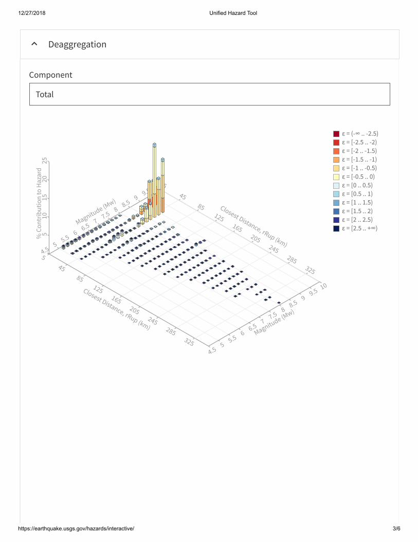
Deaggregation
Component
Total
ε = (-∞ .. -2.5)ε = [-2.5 .. -2)ε = [-2 .. -1.5)ε = [-1.5 .. -1)ε = [-1 .. -0.5)ε = [-0.5 .. 0)ε = [0 .. 0.5)ε = [0.5 .. 1)ε = [1 .. 1.5)ε = [1.5 .. 2)ε = [2 .. 2.5)ε = [2.5 .. +∞)
545
85125
Closest Distance, rRup (km)
165205
245285
325
109.5
98.5
8
Magnitude (Mw)
7.57
6.56
5.55
4.5
510
% C
ontr
ibut
ion
to H
azar
d15
2025
545
85125
165205
Closest Distance, rRup (km)245
285325
109.5
98.5
87.5
76.5
Magnitude (Mw)
65.5
54.5

12/27/2018 Unified Hazard Tool
https://earthquake.usgs.gov/hazards/interactive/ 4/6
Summary statistics for, Deaggregation: Total
Deaggregation targets
Return period: 475 yrsExceedance rate: 0.0021052632 yr⁻¹PGA ground motion: 0.31552935 g
Recovered targets
Return period: 473.53064 yrsExceedance rate: 0.0021117958 yr⁻¹
Totals
Binned: 100 %Residual: 0 %Trace: 0.79 %
Mean (for all sources)
r: 39.49 kmm: 8.45ε₀: -0.41 σ
Mode (largest r-m bin)
r: 43.87 kmm: 8.68ε₀: -0.42 σContribution: 19.82 %
Mode (largest ε₀ bin)
r: 44.39 kmm: 8.67ε₀: -0.32 σContribution: 12.68 %
Discretization
r: min = 0.0, max = 1000.0, Δ = 20.0 kmm: min = 4.4, max = 9.4, Δ = 0.2ε: min = -3.0, max = 3.0, Δ = 0.5 σ
Epsilon keys
ε0: [-∞ ‥ -2.5)ε1: [-2.5 ‥ -2.0)ε2: [-2.0 ‥ -1.5)ε3: [-1.5 ‥ -1.0)ε4: [-1.0 ‥ -0.5)ε5: [-0.5 ‥ 0.0)ε6: [0.0 ‥ 0.5)ε7: [0.5 ‥ 1.0)ε8: [1.0 ‥ 1.5)ε9: [1.5 ‥ 2.0)ε10: [2.0 ‥ 2.5)ε11: [2.5 ‥ +∞]
12/27/2018 Unified Hazard Tool
https://earthquake.usgs.gov/hazards/interactive/ 5/6
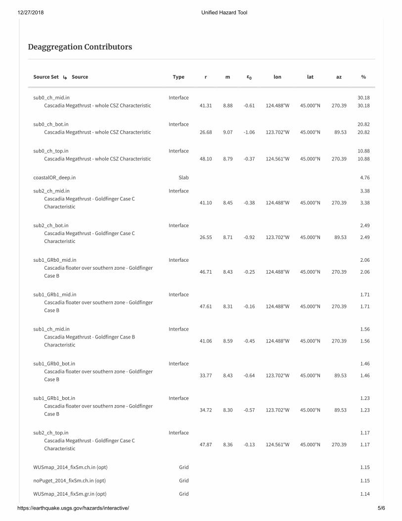
Deaggregation Contributors
Source Set Source Type r m ε0 lon lat az %
sub0_ch_mid.in Interface 30.18Cascadia Megathrust - whole CSZ Characteristic 41.31 8.88 -0.61 124.488°W 45.000°N 270.39 30.18
sub0_ch_bot.in Interface 20.82Cascadia Megathrust - whole CSZ Characteristic 26.68 9.07 -1.06 123.702°W 45.000°N 89.53 20.82
sub0_ch_top.in Interface 10.88Cascadia Megathrust - whole CSZ Characteristic 48.10 8.79 -0.37 124.561°W 45.000°N 270.39 10.88
coastalOR_deep.in Slab 4.76
sub2_ch_mid.in Interface 3.38Cascadia Megathrust - Goldfinger Case CCharacteristic
41.10 8.45 -0.38 124.488°W 45.000°N 270.39 3.38
sub2_ch_bot.in Interface 2.49Cascadia Megathrust - Goldfinger Case CCharacteristic
26.55 8.71 -0.92 123.702°W 45.000°N 89.53 2.49
sub1_GRb0_mid.in Interface 2.06Cascadia floater over southern zone - GoldfingerCase B
46.71 8.43 -0.25 124.488°W 45.000°N 270.39 2.06
sub1_GRb1_mid.in Interface 1.71Cascadia floater over southern zone - GoldfingerCase B
47.61 8.31 -0.16 124.488°W 45.000°N 270.39 1.71
sub1_ch_mid.in Interface 1.56Cascadia Megathrust - Goldfinger Case BCharacteristic
41.06 8.59 -0.45 124.488°W 45.000°N 270.39 1.56
sub1_GRb0_bot.in Interface 1.46Cascadia floater over southern zone - GoldfingerCase B
33.77 8.43 -0.64 123.702°W 45.000°N 89.53 1.46
sub1_GRb1_bot.in Interface 1.23Cascadia floater over southern zone - GoldfingerCase B
34.72 8.30 -0.57 123.702°W 45.000°N 89.53 1.23
sub2_ch_top.in Interface 1.17Cascadia Megathrust - Goldfinger Case CCharacteristic
47.87 8.36 -0.13 124.561°W 45.000°N 270.39 1.17
WUSmap_2014_fixSm.ch.in (opt) Grid 1.15
noPuget_2014_fixSm.ch.in (opt) Grid 1.15
WUSmap_2014_fixSm.gr.in (opt) Grid 1.14

12/27/2018 Unified Hazard Tool
https://earthquake.usgs.gov/hazards/interactive/ 6/6
Source Set Source Type r m ε0 lon lat az %
noPuget_2014_fixSm.gr.in (opt) Grid 1.14
sub1_ch_bot.in Interface 1.12Cascadia Megathrust - Goldfinger Case BCharacteristic
26.68 8.83 -0.96 123.702°W 45.000°N 89.53 1.12