Embed Size (px)
Citation preview
Geotechnical Engineering Report South Shore Carter Lake Campground Expansion
Northwest of CR 31 and Cougar Run Lane
Larimer County, Colorado
July 15, 2016
Terracon Project No. 20165057
Prepared for:
Larimer County Colorado
Fort Collins, Colorado
Prepared by:
Terracon Consultants, Inc.
Fort Collins, Colorado
TABLE OF CONTENTS
EXECUTIVE SUMMARY ............................................................................................................ i 1.0 INTRODUCTION .............................................................................................................1 2.0 PROJECT INFORMATION .............................................................................................1
2.1 Project Description ...............................................................................................1 2.2 Site Location and Description...............................................................................2
3.0 SUBSURFACE CONDITIONS ........................................................................................2 3.1 Typical Subsurface Profile ...................................................................................2 3.2 Laboratory Testing ...............................................................................................3 3.3 Corrosion Protection (Water-Soluble Sulfates) .....................................................3 3.4 Groundwater ........................................................................................................3
4.0 RECOMMENDATIONS FOR DESIGN AND CONSTRUCTION ......................................4 4.1 Geotechnical Considerations ...............................................................................4
4.1.1 Expansive Soils ........................................................................................4 4.1.2 Foundation Recommendations .................................................................5
4.2 Earthwork.............................................................................................................5 4.2.1 Site Preparation ........................................................................................5 4.2.2 Demolition ................................................................................................5 4.2.3 Excavation ................................................................................................6 4.2.4 Subgrade Preparation ...............................................................................6 4.2.5 Fill Materials and Placement ......................................................................7 4.2.6 Compaction Requirements ........................................................................8 4.2.7 Utility Trench Backfill ................................................................................9 4.2.8 Grading and Drainage ...............................................................................9
4.3 Foundations .........................................................................................................9 4.3.1 Spread Footings - Design Recommendations .........................................10 4.3.2 Spread Footings - Construction Considerations ......................................11
4.4 Seismic Considerations......................................................................................11 4.5 Floor Systems ....................................................................................................12
4.5.1 Floor System - Design Recommendations ..............................................12 4.5.2 Floor Systems - Construction Considerations .........................................13
4.6 Roadways ..........................................................................................................13 4.6.1 Roadways – Subgrade Preparation and Design .....................................13
5.0 GENERAL COMMENTS ...............................................................................................13
TABLE OF CONTENTS (continued)
Appendix A – FIELD EXPLORATION
Exhibit A-1 Site Location Map
Exhibit A-2 Exploration Plan
Exhibit A-3 Field Exploration Description
Exhibits A-4 to A-16 Boring Logs
Appendix B – LABORATORY TESTING
Exhibit B-1 Laboratory Testing Description
Exhibit B-2 Atterberg Limits Test Results
Exhibits B-3 and B-4 Grain-size Distribution Test Results
Exhibits B-5 and B-6 Swell-consolidation Test Results
Exhibit B-7 Water-Soluble Sulfate Test Results
Appendix C – SUPPORTING DOCUMENTS
Exhibit C-1 General Notes
Exhibit C-2 Unified Soil Classification System
Exhibit C-3 Description of Rock Properties
Exhibit C-4 Laboratory Test Significance and Purpose
Exhibits C-5 and C-6 Report Terminology
Geotechnical Engineering Report South Shore Carter Lake Campground Expansion ■ Larimer County, Colorado July 15, 2016 ■ Terracon Project No. 20165057
Responsive ■ Resourceful ■ Reliable i
EXECUTIVE SUMMARY
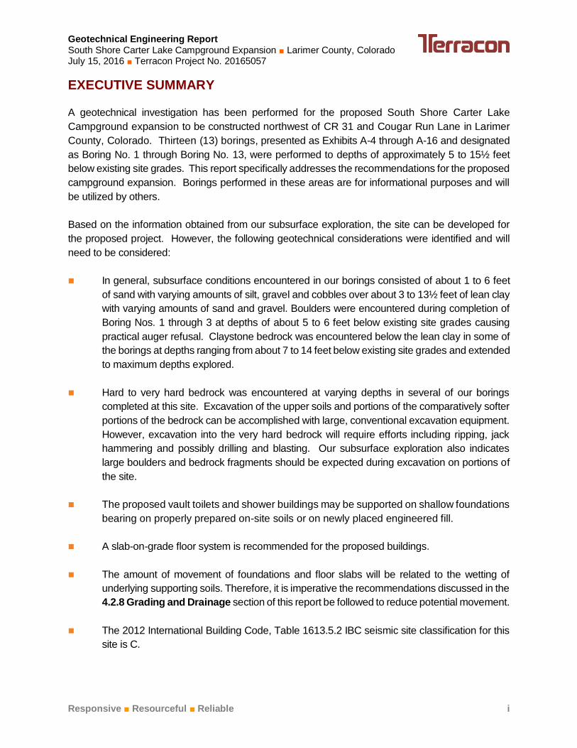
A geotechnical investigation has been performed for the proposed South Shore Carter Lake
Campground expansion to be constructed northwest of CR 31 and Cougar Run Lane in Larimer
County, Colorado. Thirteen (13) borings, presented as Exhibits A-4 through A-16 and designated
as Boring No. 1 through Boring No. 13, were performed to depths of approximately 5 to 15½ feet
below existing site grades. This report specifically addresses the recommendations for the proposed
campground expansion. Borings performed in these areas are for informational purposes and will
be utilized by others.
Based on the information obtained from our subsurface exploration, the site can be developed for
the proposed project. However, the following geotechnical considerations were identified and will
need to be considered:
In general, subsurface conditions encountered in our borings consisted of about 1 to 6 feet
of sand with varying amounts of silt, gravel and cobbles over about 3 to 13½ feet of lean clay
with varying amounts of sand and gravel. Boulders were encountered during completion of
Boring Nos. 1 through 3 at depths of about 5 to 6 feet below existing site grades causing
practical auger refusal. Claystone bedrock was encountered below the lean clay in some of
the borings at depths ranging from about 7 to 14 feet below existing site grades and extended
to maximum depths explored.
Hard to very hard bedrock was encountered at varying depths in several of our borings
completed at this site. Excavation of the upper soils and portions of the comparatively softer
portions of the bedrock can be accomplished with large, conventional excavation equipment.
However, excavation into the very hard bedrock will require efforts including ripping, jack
hammering and possibly drilling and blasting. Our subsurface exploration also indicates
large boulders and bedrock fragments should be expected during excavation on portions of
the site.
The proposed vault toilets and shower buildings may be supported on shallow foundations
bearing on properly prepared on-site soils or on newly placed engineered fill.
A slab-on-grade floor system is recommended for the proposed buildings.
The amount of movement of foundations and floor slabs will be related to the wetting of
underlying supporting soils. Therefore, it is imperative the recommendations discussed in the
4.2.8 Grading and Drainage section of this report be followed to reduce potential movement.
The 2012 International Building Code, Table 1613.5.2 IBC seismic site classification for this
site is C.
Geotechnical Engineering Report South Shore Carter Lake Campground Expansion ■ Larimer County, Colorado July 15, 2016 ■ Terracon Project No. 20165057
Responsive ■ Resourceful ■ Reliable ii
Close monitoring of the construction operations discussed herein will be critical in achieving
the design subgrade support. We therefore recommend that Terracon be retained to
monitor this portion of the work.
This summary should be used in conjunction with the entire report for design purposes. It should
be recognized that details were not included or fully developed in this section, and the report must
be read in its entirety for a comprehensive understanding of the items contained herein. The section
titled GENERAL COMMENTS should be read for an understanding of the report limitations.
Responsive ■ Resourceful ■ Reliable 1
GEOTECHNICAL ENGINEERING REPORT
South Shore Carter Lake Campground Expansion
Northwest of CR 31 and Cougar Run Lane
Larimer County, Colorado Terracon Project No. 20165057
July 15, 2016
1.0 INTRODUCTION
This report presents the results of our geotechnical engineering services performed for the
proposed South Shore Carter Lake Campground expansion to be located northwest of CR 31 and
Cougar Run Lane in Larimer County, Colorado (Exhibit A-1). The purpose of these services is to
provide information and geotechnical engineering recommendations relative to:
subsurface soil and bedrock conditions foundation design and construction
groundwater conditions floor slab design and construction
seismic considerations access road construction
earthwork
excavation considerations
grading and drainage
Our geotechnical engineering scope of work for this project included the initial site visit, the
advancement of thirteen test borings to depths ranging from approximately 5 to 15½ feet below
existing site grades, laboratory testing for soil engineering properties and engineering analyses
to provide excavation, foundation, floor system and roadway design and construction
recommendations.
Logs of the borings along with an Exploration Plan (Exhibit A-2) are included in Appendix A. The
results of the laboratory testing performed on soil and bedrock samples obtained from the site
during the field exploration are included in Appendix B.
2.0 PROJECT INFORMATION
2.1 Project Description
Item Description
Site layout Refer to the Exploration Plan (Exhibit A-2 in Appendix A)
Structures
The proposed construction includes removing and replacing multiple
vault toilets on site, a proposed shower building and additional
campsites with associated access roads and parking areas.
Below-grade areas No below-grades areas planned
Geotechnical Engineering Report South Shore Carter Lake Campground Expansion ■ Larimer County, Colorado July 15, 2016 ■ Terracon Project No. 20165057
Responsive ■ Resourceful ■ Reliable 2
Item Description
Traffic loading
Project plans indicate the proposed construction will include new
drive lanes and parking areas for the additional campsites. We
anticipate gravelly-surfacing will be used for the proposed roadways.
2.2 Site Location and Description
Item Description
Location The project site is located northwest of CR 31 and Cougar Run Lane
in Larimer County, Colorado.
Existing site features
The site is currently multiple drive-in campground sites with
associated gravel-surfaced roads, bathrooms, picnic areas and a
sand volleyball court.
Surrounding developments
The site is surrounded by undeveloped land to the east, south and
west and the southern edge of Carter Lake borders the north side of
the site.
Current ground cover
The ground is currently covered with native grasses and weeds,
some native forested areas and some areas of gravel for access
roads around the campsites.
Existing topography
The north side of the site has steep embankments and sits higher
than the rest of the site. The site then slopes gradually down toward
the south and is relatively flat with some rolling hills in the large field
on the southern end of site.
3.0 SUBSURFACE CONDITIONS
3.1 Typical Subsurface Profile
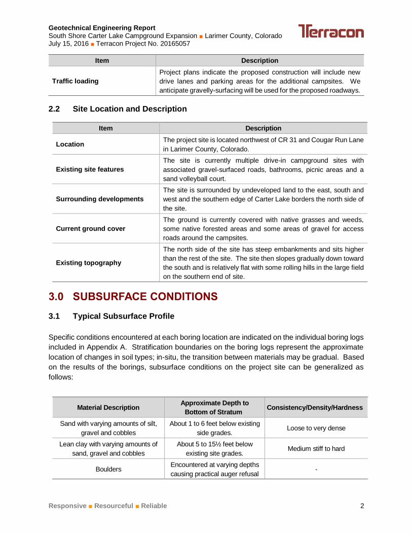
Specific conditions encountered at each boring location are indicated on the individual boring logs
included in Appendix A. Stratification boundaries on the boring logs represent the approximate
location of changes in soil types; in-situ, the transition between materials may be gradual. Based
on the results of the borings, subsurface conditions on the project site can be generalized as
follows:
Material Description Approximate Depth to
Bottom of Stratum Consistency/Density/Hardness
Sand with varying amounts of silt,
gravel and cobbles
About 1 to 6 feet below existing
side grades. Loose to very dense
Lean clay with varying amounts of
sand, gravel and cobbles
About 5 to 15½ feet below
existing site grades. Medium stiff to hard
Boulders Encountered at varying depths
causing practical auger refusal -
Geotechnical Engineering Report South Shore Carter Lake Campground Expansion ■ Larimer County, Colorado July 15, 2016 ■ Terracon Project No. 20165057
Responsive ■ Resourceful ■ Reliable 3
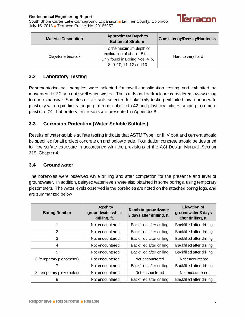
Material Description Approximate Depth to
Bottom of Stratum Consistency/Density/Hardness
Claystone bedrock
To the maximum depth of
exploration of about 15 feet.
Only found in Boring Nos. 4, 5,
8, 9, 10, 11, 12 and 13
Hard to very hard
3.2 Laboratory Testing
Representative soil samples were selected for swell-consolidation testing and exhibited no
movement to 2.2 percent swell when wetted. The sands and bedrock are considered low-swelling
to non-expansive. Samples of site soils selected for plasticity testing exhibited low to moderate
plasticity with liquid limits ranging from non-plastic to 42 and plasticity indices ranging from non-
plastic to 24. Laboratory test results are presented in Appendix B.
3.3 Corrosion Protection (Water-Soluble Sulfates)
Results of water-soluble sulfate testing indicate that ASTM Type I or II, V portland cement should
be specified for all project concrete on and below grade. Foundation concrete should be designed
for low sulfate exposure in accordance with the provisions of the ACI Design Manual, Section
318, Chapter 4.
3.4 Groundwater
The boreholes were observed while drilling and after completion for the presence and level of
groundwater. In addition, delayed water levels were also obtained in some borings, using temporary
piezometers. The water levels observed in the boreholes are noted on the attached boring logs, and
are summarized below
Boring Number
Depth to
groundwater while
drilling, ft.
Depth to groundwater
3 days after drilling, ft.
Elevation of
groundwater 3 days
after drilling, ft.
1 Not encountered Backfilled after drilling Backfilled after drilling
2 Not encountered Backfilled after drilling Backfilled after drilling
3 Not encountered Backfilled after drilling Backfilled after drilling
4 Not encountered Backfilled after drilling Backfilled after drilling
5 Not encountered Backfilled after drilling Backfilled after drilling
6 (temporary piezometer) Not encountered Not encountered Not encountered
7 Not encountered Backfilled after drilling Backfilled after drilling
8 (temporary piezometer) Not encountered Not encountered Not encountered
9 Not encountered Backfilled after drilling Backfilled after drilling
Geotechnical Engineering Report South Shore Carter Lake Campground Expansion ■ Larimer County, Colorado July 15, 2016 ■ Terracon Project No. 20165057
Responsive ■ Resourceful ■ Reliable 4
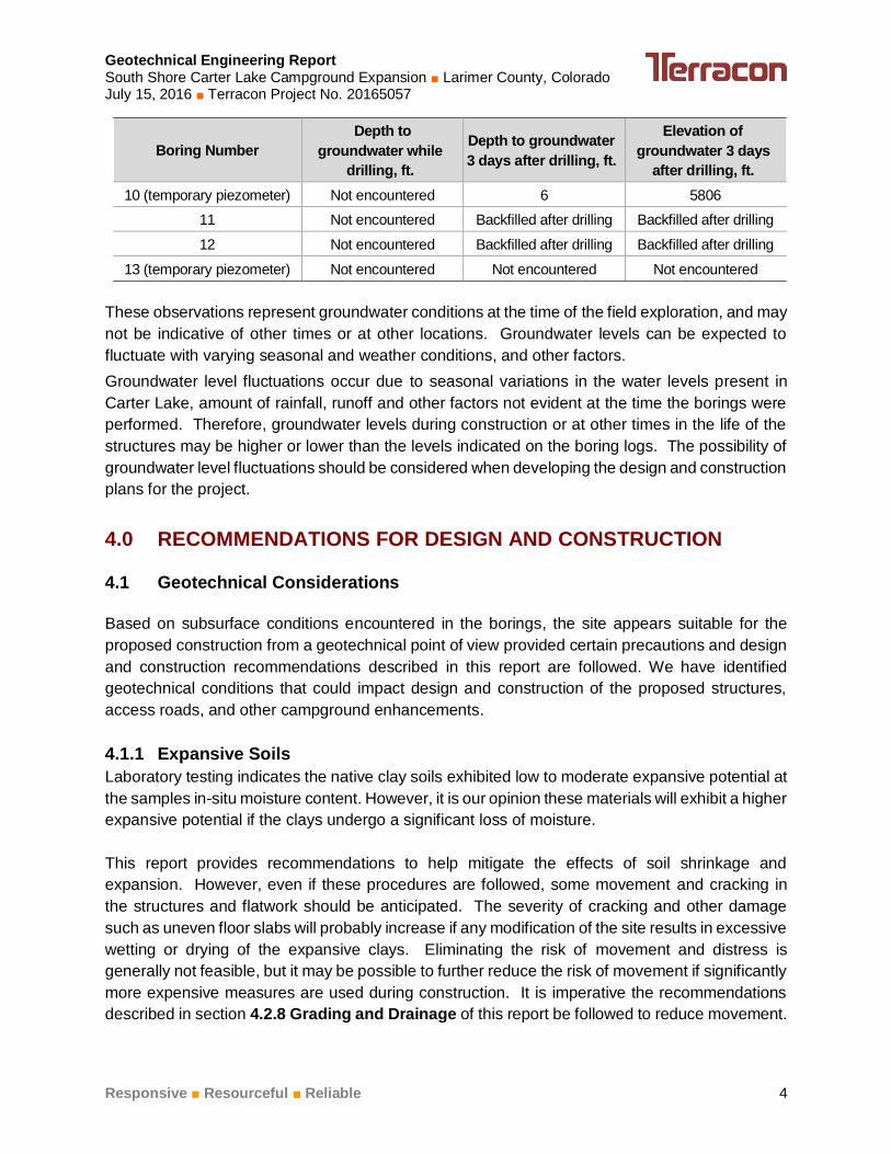
Boring Number
Depth to
groundwater while
drilling, ft.
Depth to groundwater
3 days after drilling, ft.
Elevation of
groundwater 3 days
after drilling, ft.
10 (temporary piezometer) Not encountered 6 5806
11 Not encountered Backfilled after drilling Backfilled after drilling
12 Not encountered Backfilled after drilling Backfilled after drilling
13 (temporary piezometer) Not encountered Not encountered Not encountered
These observations represent groundwater conditions at the time of the field exploration, and may
not be indicative of other times or at other locations. Groundwater levels can be expected to
fluctuate with varying seasonal and weather conditions, and other factors.
Groundwater level fluctuations occur due to seasonal variations in the water levels present in
Carter Lake, amount of rainfall, runoff and other factors not evident at the time the borings were
performed. Therefore, groundwater levels during construction or at other times in the life of the
structures may be higher or lower than the levels indicated on the boring logs. The possibility of
groundwater level fluctuations should be considered when developing the design and construction
plans for the project.
4.0 RECOMMENDATIONS FOR DESIGN AND CONSTRUCTION
4.1 Geotechnical Considerations
Based on subsurface conditions encountered in the borings, the site appears suitable for the
proposed construction from a geotechnical point of view provided certain precautions and design
and construction recommendations described in this report are followed. We have identified
geotechnical conditions that could impact design and construction of the proposed structures,
access roads, and other campground enhancements.
4.1.1 Expansive Soils
Laboratory testing indicates the native clay soils exhibited low to moderate expansive potential at
the samples in-situ moisture content. However, it is our opinion these materials will exhibit a higher
expansive potential if the clays undergo a significant loss of moisture.
This report provides recommendations to help mitigate the effects of soil shrinkage and
expansion. However, even if these procedures are followed, some movement and cracking in
the structures and flatwork should be anticipated. The severity of cracking and other damage
such as uneven floor slabs will probably increase if any modification of the site results in excessive
wetting or drying of the expansive clays. Eliminating the risk of movement and distress is
generally not feasible, but it may be possible to further reduce the risk of movement if significantly
more expensive measures are used during construction. It is imperative the recommendations
described in section 4.2.8 Grading and Drainage of this report be followed to reduce movement.
Geotechnical Engineering Report South Shore Carter Lake Campground Expansion ■ Larimer County, Colorado July 15, 2016 ■ Terracon Project No. 20165057
Responsive ■ Resourceful ■ Reliable 5
4.1.2 Foundation Recommendations
The proposed vault toilets and shower building may be supported on a spread footing foundation
system bearing on properly prepared on-site soils or newly placed engineered fill. We
recommend a slab-on-grade for the interior floor system of the proposed building. Even when
bearing on properly prepared soils, movement of the slab-on-grade floor system is possible
should the subgrade soils undergo an increase in moisture content. We estimate movement of
about 1 inch is possible. If the owner cannot accept the risk of slab movement, a structural floor
should be used.
4.2 Earthwork
The following presents recommendations for site preparation, excavation, subgrade preparation
and placement of engineered fills on the project. All earthwork on the project should be observed
and evaluated by Terracon on a full-time basis. The evaluation of earthwork should include
observation of over-excavation operations, testing of engineered fills, subgrade preparation,
subgrade stabilization, and other geotechnical conditions exposed during the construction of the
project.
4.2.1 Site Preparation
Prior to placing any fill, strip and remove existing vegetation and any other deleterious materials
from the proposed construction areas.
Stripped organic materials should be wasted from the site or used to re-vegetate landscaped areas
or exposed slopes after completion of grading operations. Prior to the placement of fills, the site
should be graded to create a relatively level surface to receive fill, and to provide for a relatively
uniform thickness of fill beneath proposed structures.
If fill is placed in areas of the site where existing slopes are steeper than 5:1 (horizontal:vertical),
the area should be benched to reduce the potential for slippage between existing slopes and fills.
Benches should be wide enough to accommodate compaction and earth moving equipment, and
to allow placement of horizontal lifts of fill.
4.2.2 Demolition
Demolition of the existing vault toilets should include complete removal of all foundation systems,
below-grade structural elements, and exterior flat work within the proposed construction area. This
should include removal of any utilities to be abandoned along with any loose utility trench backfill or
loose backfill found adjacent to existing foundations. All materials derived from the demolition of
existing structures should be removed from the site.
Consideration could be given to re-using the concrete provided the materials are processed and
uniformly blended with the on-site soils. Concrete materials should be processed to a maximum
size of 2-inches and blended at a ratio of 30 percent concrete to 70 percent of on-site soils.
Geotechnical Engineering Report South Shore Carter Lake Campground Expansion ■ Larimer County, Colorado July 15, 2016 ■ Terracon Project No. 20165057
Responsive ■ Resourceful ■ Reliable 6
4.2.3 Excavation
Excavation penetrating the upper strata of soils and portions of the comparatively softer bedrock
can be accomplished with large, conventional excavation equipment. Excavation penetrating the
bedrock or cemented soils or soil with large cobbles and boulders may require the use of specialized
heavy-duty equipment, together with ripping or jack-hammering drilling and blasting to advance the
excavation and facilitate rock break-up and removal. Consideration should be given to obtaining a
unit price for difficult excavation in the contract documents for the project.
The soils to be excavated can vary significantly across the site as their classifications are based
solely on the materials encountered in widely-spaced exploratory test borings. The contractor
should verify that similar conditions exist throughout the proposed area of excavation. If different
subsurface conditions are encountered at the time of construction, the actual conditions should be
evaluated to determine any excavation modifications necessary to maintain safe conditions.
Although evidence of fills or underground facilities such as septic tanks and utilities was not
observed during the site reconnaissance, such features could be encountered during construction.
If unexpected fills or underground facilities are encountered, such features should be removed and
the excavation thoroughly cleaned prior to backfill placement and/or construction.
Any over-excavation that extends below the bottom of foundation elevation for the proposed
restroom building should extend laterally beyond all edges of the foundations at least 8 inches per
foot of over-excavation depth below the foundation base elevation. The over-excavation should be
backfilled to the foundation base elevation in accordance with the recommendations presented in
this report.
Depending upon depth of excavation and seasonal conditions, surface water infiltration and/or
groundwater may be encountered in excavations on the site. It is anticipated that pumping from
sumps may be utilized to control water within excavations.
The subgrade soil conditions should be evaluated during the excavation process and the stability
of the soils determined at that time by the contractors’ Competent Person. Slope inclinations flatter
than the OSHA maximum values may have to be used. The individual contractor(s) should be
made responsible for designing and constructing stable, temporary excavations as required to
maintain stability of both the excavation sides and bottom. All excavations should be sloped or
shored in the interest of safety following local, and federal regulations, including current OSHA
excavation and trench safety standards.
As a safety measure, it is recommended that all vehicles and soil piles be kept a minimum lateral
distance from the crest of the slope equal to the slope height. The exposed slope face should be
protected against the elements
4.2.4 Subgrade Preparation
After the vegetative layer has been removed from the construction areas, the top 8 inches of the
exposed ground surface should be scarified, moisture conditioned, and recompacted to at least
Geotechnical Engineering Report South Shore Carter Lake Campground Expansion ■ Larimer County, Colorado July 15, 2016 ■ Terracon Project No. 20165057
Responsive ■ Resourceful ■ Reliable 7
95 percent of the maximum dry unit weight as determined by AASHTO T99 before any new fill or
roadway material is placed.
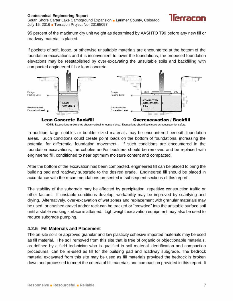
If pockets of soft, loose, or otherwise unsuitable materials are encountered at the bottom of the
foundation excavations and it is inconvenient to lower the foundations, the proposed foundation
elevations may be reestablished by over-excavating the unsuitable soils and backfilling with
compacted engineered fill or lean concrete.
In addition, large cobbles or boulder-sized materials may be encountered beneath foundation
areas. Such conditions could create point loads on the bottom of foundations, increasing the
potential for differential foundation movement. If such conditions are encountered in the
foundation excavations, the cobbles and/or boulders should be removed and be replaced with
engineered fill, conditioned to near optimum moisture content and compacted.
After the bottom of the excavation has been compacted, engineered fill can be placed to bring the
building pad and roadway subgrade to the desired grade. Engineered fill should be placed in
accordance with the recommendations presented in subsequent sections of this report.
The stability of the subgrade may be affected by precipitation, repetitive construction traffic or
other factors. If unstable conditions develop, workability may be improved by scarifying and
drying. Alternatively, over-excavation of wet zones and replacement with granular materials may
be used, or crushed gravel and/or rock can be tracked or “crowded” into the unstable surface soil
until a stable working surface is attained. Lightweight excavation equipment may also be used to
reduce subgrade pumping.
4.2.5 Fill Materials and Placement
The on-site soils or approved granular and low plasticity cohesive imported materials may be used
as fill material. The soil removed from this site that is free of organic or objectionable materials,
as defined by a field technician who is qualified in soil material identification and compaction
procedures, can be re-used as fill for the building pad and roadway subgrade. The bedrock
material excavated from this site may be used as fill materials provided the bedrock is broken
down and processed to meet the criteria of fill materials and compaction provided in this report. It
Geotechnical Engineering Report South Shore Carter Lake Campground Expansion ■ Larimer County, Colorado July 15, 2016 ■ Terracon Project No. 20165057
Responsive ■ Resourceful ■ Reliable 8
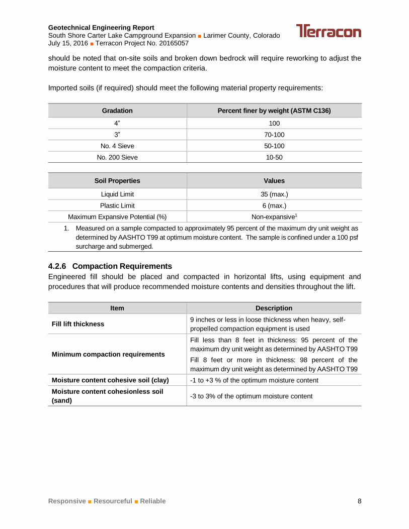
should be noted that on-site soils and broken down bedrock will require reworking to adjust the
moisture content to meet the compaction criteria.
Imported soils (if required) should meet the following material property requirements:
Gradation Percent finer by weight (ASTM C136)
4” 100
3” 70-100
No. 4 Sieve 50-100
No. 200 Sieve 10-50
Soil Properties Values
Liquid Limit 35 (max.)
Plastic Limit 6 (max.)
Maximum Expansive Potential (%) Non-expansive1
1. Measured on a sample compacted to approximately 95 percent of the maximum dry unit weight as
determined by AASHTO T99 at optimum moisture content. The sample is confined under a 100 psf
surcharge and submerged.
4.2.6 Compaction Requirements
Engineered fill should be placed and compacted in horizontal lifts, using equipment and
procedures that will produce recommended moisture contents and densities throughout the lift.
Item Description
Fill lift thickness 9 inches or less in loose thickness when heavy, self-
propelled compaction equipment is used
Minimum compaction requirements
Fill less than 8 feet in thickness: 95 percent of the
maximum dry unit weight as determined by AASHTO T99
Fill 8 feet or more in thickness: 98 percent of the
maximum dry unit weight as determined by AASHTO T99
Moisture content cohesive soil (clay) -1 to +3 % of the optimum moisture content
Moisture content cohesionless soil
(sand) -3 to 3% of the optimum moisture content
Geotechnical Engineering Report South Shore Carter Lake Campground Expansion ■ Larimer County, Colorado July 15, 2016 ■ Terracon Project No. 20165057
Responsive ■ Resourceful ■ Reliable 9
Item Description
1. We recommend engineered fill be tested for moisture content and compaction during placement.
Should the results of the in-place density tests indicate the specified moisture or compaction limits
have not been met, the area represented by the test should be reworked and retested as required
until the specified moisture and compaction requirements are achieved.
2. Specifically, moisture levels should be maintained low enough to allow for satisfactory compaction to
be achieved without the fill material pumping when proofrolled.
3. Moisture conditioned clay materials should not be allowed to dry out. A loss of moisture within these
materials could result in an increase in the material’s expansive potential. Subsequent wetting of
these materials could result in undesirable movement.
4.2.7 Utility Trench Backfill
All trench excavations for the proposed shower building or other areas of the site should be made
with sufficient working space to permit construction including backfill placement and compaction.
All underground piping within or near the proposed structures should be designed with flexible
couplings, so minor deviations in alignment do not result in breakage or distress. Utility knockouts
in foundation walls should be oversized to accommodate differential movements. It is imperative
that utility trenches be properly backfilled with relatively clean materials. If utility trenches are
backfilled with relatively clean granular material, they should be capped with at least 18 inches of
cohesive fill to reduce the infiltration and conveyance of surface water through the trench backfill.
It is strongly recommended that a representative of Terracon provide full-time observation and
compaction testing of trench backfill within building area.
4.2.8 Grading and Drainage
All grades must be adjusted to provide effective drainage away from the proposed building and
existing buildings during construction and maintained throughout the life of the proposed project.
Infiltration of water into foundation excavations must be prevented during construction. Water
permitted to pond near or adjacent to the perimeter of the structures (either during or post-
construction) can result in significantly higher soil movements than those discussed in this report.
As a result, any estimations of potential movement described in this report cannot be relied upon
if positive drainage is not obtained and maintained, and water is allowed to infiltrate the fill and/or
subgrade.
4.3 Foundations
The proposed vault toilet and shower building can be supported by a shallow, spread footing
foundation system. Design recommendations for foundations for the proposed structure and
related structural elements are presented in the following paragraphs.
Geotechnical Engineering Report South Shore Carter Lake Campground Expansion ■ Larimer County, Colorado July 15, 2016 ■ Terracon Project No. 20165057
Responsive ■ Resourceful ■ Reliable 10
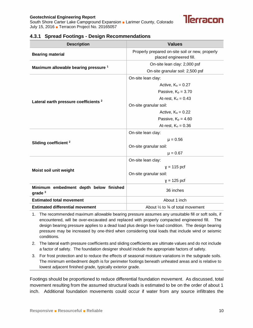
4.3.1 Spread Footings - Design Recommendations
Description Values
Bearing material Properly prepared on-site soil or new, properly
placed engineered fill.
Maximum allowable bearing pressure 1 On-site lean clay: 2,000 psf
On-site granular soil: 2,500 psf
Lateral earth pressure coefficients 2
On-site lean clay:
Active, Ka = 0.27
Passive, Kp = 3.70
At-rest, Ko = 0.43
On-site granular soil:
Active, Ka = 0.22
Passive, Kp = 4.60
At-rest, Ko = 0.36
Sliding coefficient 2
On-site lean clay:
µ = 0.56
On-site granular soil:
µ = 0.67
Moist soil unit weight
On-site lean clay:
ɣ = 115 pcf
On-site granular soil:
ɣ = 125 pcf
Minimum embedment depth below finished
grade 3 36 inches
Estimated total movement About 1 inch
Estimated differential movement About ½ to ¾ of total movement
1. The recommended maximum allowable bearing pressure assumes any unsuitable fill or soft soils, if
encountered, will be over-excavated and replaced with properly compacted engineered fill. The
design bearing pressure applies to a dead load plus design live load condition. The design bearing
pressure may be increased by one-third when considering total loads that include wind or seismic
conditions.
2. The lateral earth pressure coefficients and sliding coefficients are ultimate values and do not include
a factor of safety. The foundation designer should include the appropriate factors of safety.
3. For frost protection and to reduce the effects of seasonal moisture variations in the subgrade soils.
The minimum embedment depth is for perimeter footings beneath unheated areas and is relative to
lowest adjacent finished grade, typically exterior grade.
Footings should be proportioned to reduce differential foundation movement. As discussed, total
movement resulting from the assumed structural loads is estimated to be on the order of about 1
inch. Additional foundation movements could occur if water from any source infiltrates the
Geotechnical Engineering Report South Shore Carter Lake Campground Expansion ■ Larimer County, Colorado July 15, 2016 ■ Terracon Project No. 20165057
Responsive ■ Resourceful ■ Reliable 11
foundation soils; therefore, proper drainage should be provided in the final design and during
construction and throughout the life of the structure. Failure to maintain the proper drainage as
recommended in the 4.2.8 Grading and Drainage section of this report will nullify the movement
estimates provided above.
4.3.2 Spread Footings - Construction Considerations
Spread footing construction should only be considered if the estimated foundation movement can
be tolerated. Subgrade soils beneath footings should be moisture conditioned and compacted as
described in the 4.2 Earthwork section of this report. The moisture content and compaction of
subgrade soils should be maintained until foundation construction.
Footings and foundation walls should be reinforced as necessary to reduce the potential for distress
caused by differential foundation movement.
Unstable subgrade conditions are anticipated as excavations approach the groundwater surface.
Unstable surfaces will need to be stabilized prior to backfilling excavations and/or constructing
the building foundation, floor slab and/or project pavements. The use of angular rock, recycled
concrete and/or gravel pushed or “crowded” into the yielding subgrade is considered suitable
means of stabilizing the subgrade. The use of geogrid materials in conjunction with gravel could
also be considered and could be more cost effective.
Unstable subgrade conditions should be observed by Terracon to assess the subgrade and
provide suitable alternatives for stabilization. Stabilized areas should be proof-rolled prior to
continuing construction to assess the stability of the subgrade.
Foundation excavations should be observed by Terracon. If the soil conditions encountered differ
significantly from those presented in this report, supplemental recommendations will be required.
4.4 Seismic Considerations
Code Used Site Classification
2012 International Building Code (IBC) 1 C 2
1. In general accordance with the 2012 International Building Code, Table 1613.5.2.
2. The 2012 International Building Code (IBC) requires a site soil profile determination extending a
depth of 100 feet for seismic site classification. The current scope requested does not include the
required 100 foot soil profile determination. The borings completed for this project extended to a
maximum depth of about 15½ feet and this seismic site class definition considers that similar soil and
bedrock conditions exist below the maximum depth of the subsurface exploration. Additional
exploration to deeper depths could be performed to confirm the conditions below the current depth of
exploration. Alternatively, a geophysical exploration could be utilized in order to attempt to justify a
more favorable seismic site class. However, we believe a higher seismic site class for this site is
unlikely.
Geotechnical Engineering Report South Shore Carter Lake Campground Expansion ■ Larimer County, Colorado July 15, 2016 ■ Terracon Project No. 20165057
Responsive ■ Resourceful ■ Reliable 12
4.5 Floor Systems
A slab-on-grade may be utilized for the interior floor system for the proposed vault toilets and
shower building. If the estimated movement cannot be tolerated, a structurally-supported floor
system, supported independent of the subgrade materials, is recommended.
Subgrade soils beneath interior and exterior slabs should be scarified to a depth of at least 8
inches, moisture conditioned and compacted. The moisture content and compaction of subgrade
soils should be maintained until slab construction.
4.5.1 Floor System - Design Recommendations
Even when bearing on properly prepared soils, movement of the slab-on-grade floor system is
possible should the subgrade soils undergo an increase in moisture content. We estimate
movement of about 1 inch is possible.
For structural design of concrete slabs-on-grade subjected to point loadings, a modulus of
subgrade reaction of 100 pounds per cubic inch (pci) may be used for floors supported on re-
compacted existing soils at the site. A modulus of 200 pci may be used for floors supported on
at least 1 foot of non-expansive, imported granular fill.
Additional floor slab design and construction recommendations are as follows:
Positive separations and/or isolation joints should be provided between slabs and all
foundations, columns, or utility lines to allow independent movement.
Control joints should be saw-cut in slabs in accordance with ACI Design Manual, Section
302.1R-37 8.3.12 (tooled control joints are not recommended) to control the location and
extent of cracking.
Interior utility trench backfill placed beneath slabs should be compacted in accordance
with the recommendations presented in the 4.2 Earthwork section of this report.
Floor slabs should not be constructed on frozen subgrade.
The use of a vapor retarder should be considered beneath concrete slabs that will be
covered with wood, tile, carpet or other moisture sensitive or impervious floor coverings,
or when the slab will support equipment sensitive to moisture. When conditions warrant
the use of a vapor retarder, the slab designer and slab contractor should refer to ACI
302 for procedures and cautions regarding the use and placement of a vapor retarder.
Other design and construction considerations, as outlined in the ACI Design Manual,
Section 302.1R are recommended.
Geotechnical Engineering Report South Shore Carter Lake Campground Expansion ■ Larimer County, Colorado July 15, 2016 ■ Terracon Project No. 20165057
Responsive ■ Resourceful ■ Reliable 13
4.5.2 Floor Systems - Construction Considerations
Movements of slabs-on-grade using the recommendations discussed in previous sections of this
report will likely be reduced and tend to be more uniform. The estimates discussed above assume
that the other recommendations in this report are followed. Additional movement could occur
should the subsurface soils become wetted to significant depths, which could result in potential
excessive movement causing uneven floor slabs and severe cracking. This could be due to over
watering of landscaping, poor drainage, improperly functioning drain systems, and/or broken utility
lines. Therefore, it is imperative that the recommendations presented in this report be followed.
4.6 Roadways
4.6.1 Roadways – Subgrade Preparation and Design
On most project sites, the site grading is accomplished relatively early in the construction phase.
Fills are typically placed and compacted in a uniform manner. However as construction proceeds,
the subgrade may be disturbed due to utility excavations, construction traffic, desiccation, or
rainfall/snow melt. As a result, the roadway subgrade may not be suitable for construction and
corrective action will be required. The subgrade should be carefully evaluated at the time of
roadway construction for signs of disturbance or instability. We recommend the roadway
subgrades be thoroughly proofrolled with a loaded tandem-axle dump truck prior to final grading
and placement of gravel-surfacing materials. All roadway areas should be moisture conditioned
and properly compacted to the recommendations in this report immediately prior to surfacing.
5.0 GENERAL COMMENTS
Terracon should be retained to review the final design plans and specifications so comments can
be made regarding interpretation and implementation of our geotechnical recommendations in
the design and specifications. Terracon also should be retained to provide observation and testing
services during grading, excavation, foundation construction and other earth-related construction
phases of the project.
The analysis and recommendations presented in this report are based upon the data obtained
from the borings performed at the indicated locations and from other information discussed in this
report. This report does not reflect variations that may occur between borings, across the site, or
due to the modifying effects of construction or weather. The nature and extent of such variations
may not become evident until during or after construction. If variations appear, we should be
immediately notified so that further evaluation and supplemental recommendations can be
provided.
The scope of services for this project does not include either specifically or by implication any
environmental or biological (e.g., mold, fungi, and bacteria) assessment of the site or identification
or prevention of pollutants, hazardous materials or conditions. If the owner is concerned about
the potential for such contamination or pollution, other studies should be undertaken.
Geotechnical Engineering Report South Shore Carter Lake Campground Expansion ■ Larimer County, Colorado July 15, 2016 ■ Terracon Project No. 20165057
Responsive ■ Resourceful ■ Reliable 14
This report has been prepared for the exclusive use of our client for specific application to the
project discussed and has been prepared in accordance with generally accepted geotechnical
engineering practices. No warranties, either express or implied, are intended or made. Site
safety, excavation support, and dewatering requirements are the responsibility of others. In the
event that changes in the nature, design, or location of the project as described in this report are
planned, the conclusions and recommendations contained in this report shall not be considered
valid unless Terracon reviews the changes and either verifies or modifies the conclusions of this
report in writing.
APPENDIX A
FIELD EXPLORATION
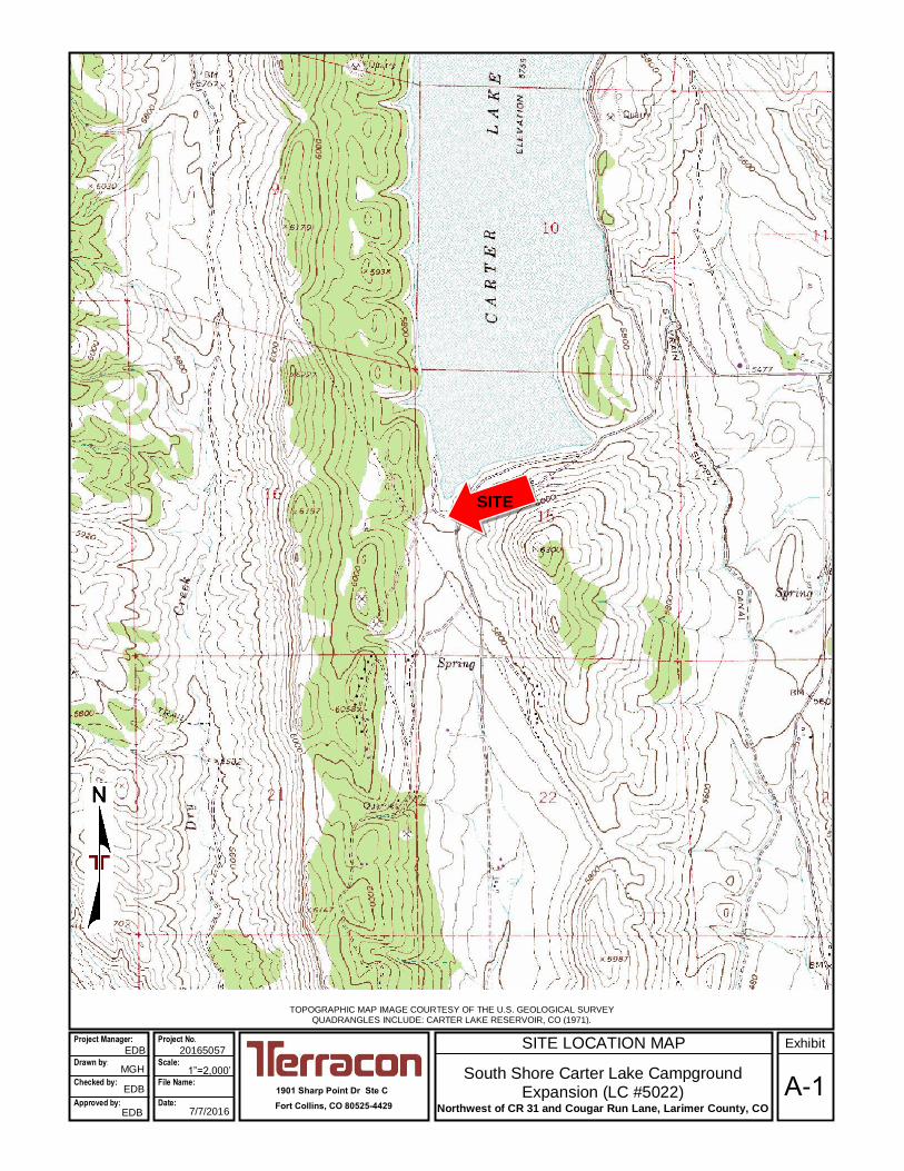
SITE LOCATION MAP
South Shore Carter Lake Campground Expansion (LC #5022)
Northwest of CR 31 and Cougar Run Lane, Larimer County, CO
TOPOGRAPHIC MAP IMAGE COURTESY OF THE U.S. GEOLOGICAL SURVEY QUADRANGLES INCLUDE: CARTER LAKE RESERVOIR, CO (1971).
1901 Sharp Point Dr Ste C
Fort Collins, CO 80525-4429
20165057
Project Manager:
Drawn by: Checked by:
Approved by:
MGH
EDB
EDB
1”=2,000’
7/7/2016
Project No.
Scale: File Name:
Date: A-1
Exhibit EDB
SITE
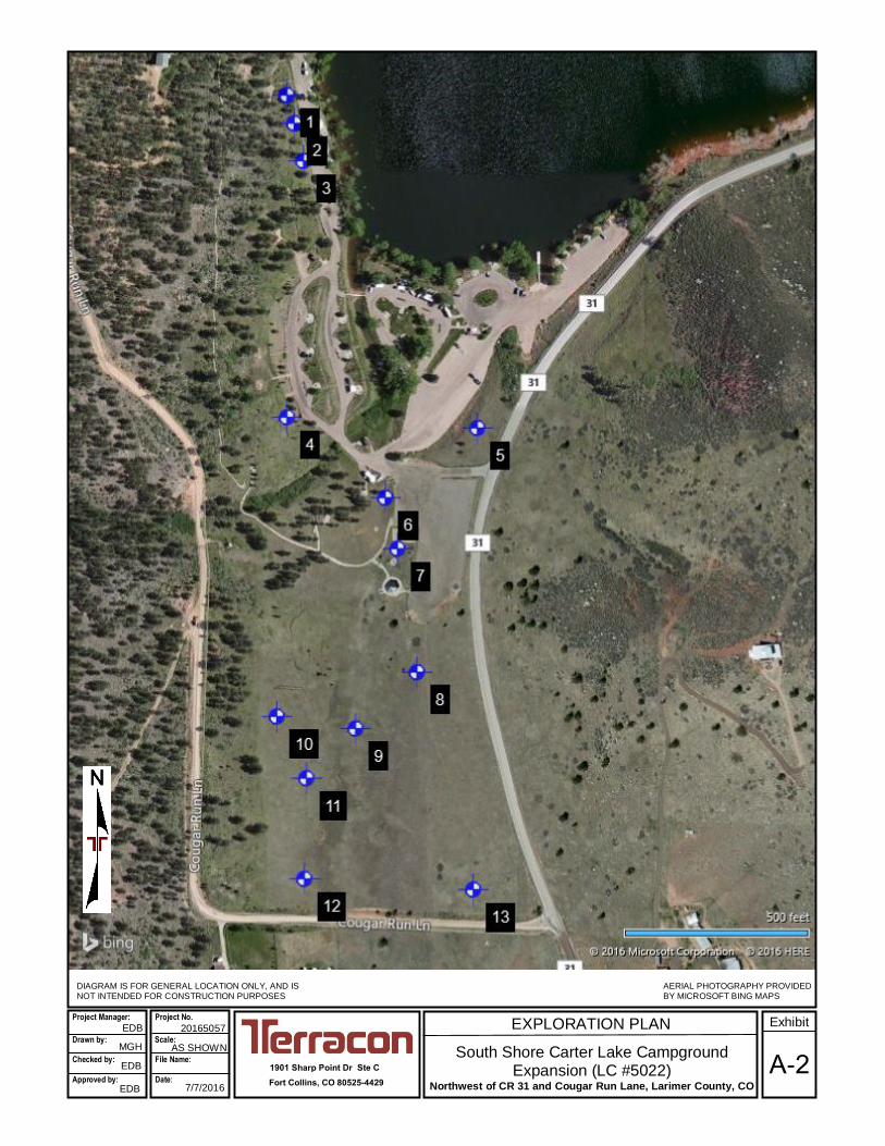
EXPLORATION PLAN
South Shore Carter Lake Campground Expansion (LC #5022)
Northwest of CR 31 and Cougar Run Lane, Larimer County, CO
1901 Sharp Point Dr Ste C
Fort Collins, CO 80525-4429
DIAGRAM IS FOR GENERAL LOCATION ONLY, AND IS NOT INTENDED FOR CONSTRUCTION PURPOSES
20165057
AERIAL PHOTOGRAPHY PROVIDED BY MICROSOFT BING MAPS
MGH
EDB
EDB
AS SHOWN
7/7/2016
Scale:
A-2
Exhibit Project Manager:
Drawn by:
Checked by:
Approved by:
Project No.
File Name:
Date:
EDB
Geotechnical Engineering Report South Shore Carter Lake Campground Expansion ■ Larimer County, Colorado July 15, 2016 ■ Terracon Project No. 20165057
Responsive ■ Resourceful ■ Reliable Exhibit A-3
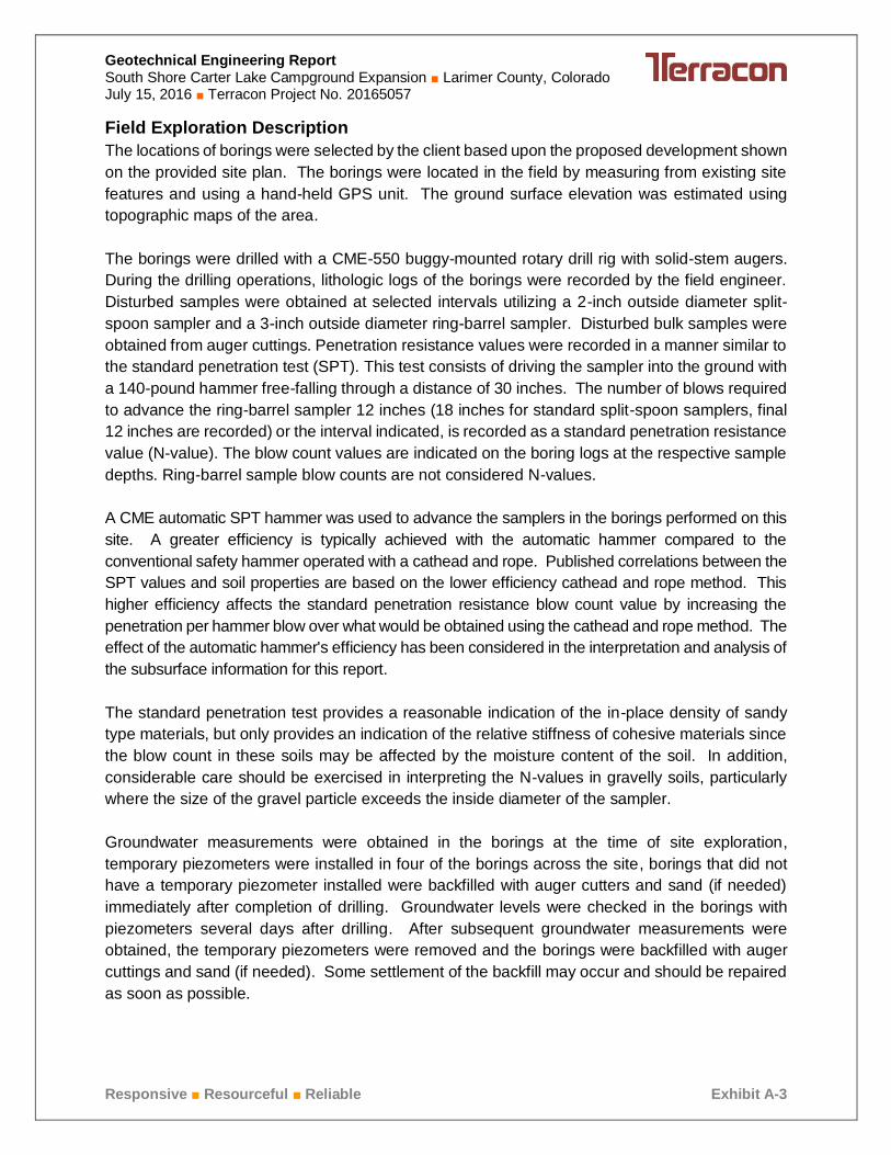
Field Exploration Description
The locations of borings were selected by the client based upon the proposed development shown
on the provided site plan. The borings were located in the field by measuring from existing site
features and using a hand-held GPS unit. The ground surface elevation was estimated using
topographic maps of the area.
The borings were drilled with a CME-550 buggy-mounted rotary drill rig with solid-stem augers.
During the drilling operations, lithologic logs of the borings were recorded by the field engineer.
Disturbed samples were obtained at selected intervals utilizing a 2-inch outside diameter split-
spoon sampler and a 3-inch outside diameter ring-barrel sampler. Disturbed bulk samples were
obtained from auger cuttings. Penetration resistance values were recorded in a manner similar to
the standard penetration test (SPT). This test consists of driving the sampler into the ground with
a 140-pound hammer free-falling through a distance of 30 inches. The number of blows required
to advance the ring-barrel sampler 12 inches (18 inches for standard split-spoon samplers, final
12 inches are recorded) or the interval indicated, is recorded as a standard penetration resistance
value (N-value). The blow count values are indicated on the boring logs at the respective sample
depths. Ring-barrel sample blow counts are not considered N-values.
A CME automatic SPT hammer was used to advance the samplers in the borings performed on this
site. A greater efficiency is typically achieved with the automatic hammer compared to the
conventional safety hammer operated with a cathead and rope. Published correlations between the
SPT values and soil properties are based on the lower efficiency cathead and rope method. This
higher efficiency affects the standard penetration resistance blow count value by increasing the
penetration per hammer blow over what would be obtained using the cathead and rope method. The
effect of the automatic hammer's efficiency has been considered in the interpretation and analysis of
the subsurface information for this report.
The standard penetration test provides a reasonable indication of the in-place density of sandy
type materials, but only provides an indication of the relative stiffness of cohesive materials since
the blow count in these soils may be affected by the moisture content of the soil. In addition,
considerable care should be exercised in interpreting the N-values in gravelly soils, particularly
where the size of the gravel particle exceeds the inside diameter of the sampler.
Groundwater measurements were obtained in the borings at the time of site exploration,
temporary piezometers were installed in four of the borings across the site, borings that did not
have a temporary piezometer installed were backfilled with auger cutters and sand (if needed)
immediately after completion of drilling. Groundwater levels were checked in the borings with
piezometers several days after drilling. After subsequent groundwater measurements were
obtained, the temporary piezometers were removed and the borings were backfilled with auger
cuttings and sand (if needed). Some settlement of the backfill may occur and should be repaired
as soon as possible.
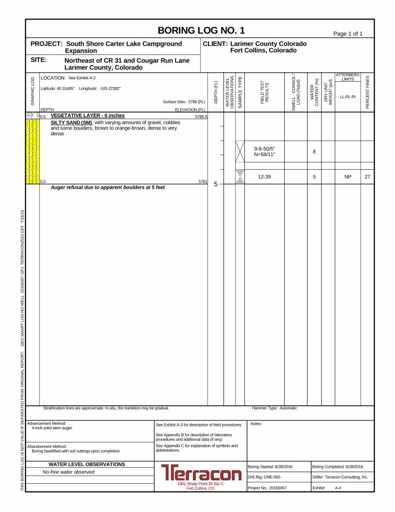
27
8
5 NP
5785.5
5781
9-8-50/5"N=59/11"
12-39
0.5
5.0
VEGETATIVE LAYER - 6 inchesSILTY SAND (SM), with varying amounts of gravel, cobblesand some boulders, brown to orange-brown, dense to verydense
Auger refusal due to apparent boulders at 5 feet
Hammer Type: AutomaticStratification lines are approximate. In-situ, the transition may be gradual.
GR
APH
ICLO
G
THIS
BOR
ING
LOG
ISN
OT
VALI
DIF
SEPA
RAT
EDFR
OM
OR
IGIN
ALR
EPO
RT.
GEO
SMAR
TLO
G-N
OW
ELL
2016
5057
.GPJ
TER
RAC
ON
2015
.GD
T7/
15/1
6
Northeast of CR 31 and Cougar Run Lane Larimer County, ColoradoSITE:
Page 1 of 1
Advancement Method:4-inch solid-stem auger
Abandonment Method:Boring backfilled with soil cuttings upon completion.
1901 Sharp Point Dr Ste CFort Collins, CO
Notes:
Project No.: 20165057
Drill Rig: CME-550
Boring Started: 6/28/2016
BORING LOG NO. 1Larimer County ColoradoCLIENT:Fort Collins, Colorado
Driller: Terracon Consulting, Inc.
Boring Completed: 6/28/2016
Exhibit: A-4
See Exhibit A-3 for description of field procedures.
See Appendix B for description of laboratoryprocedures and additional data (if any).See Appendix C for explanation of symbols andabbreviations.
PROJECT: South Shore Carter Lake CampgroundExpansion
PER
CEN
TFI
NES
WAT
ERC
ON
TEN
T(%
)
DR
YU
NIT
WEI
GH
T(p
cf)
ATTERBERGLIMITS
LL-PL-PISurface Elev.: 5786 (Ft.)
ELEVATION (Ft.) SAM
PLE
TYPE
WAT
ERLE
VEL
OBS
ERVA
TIO
NS
DEP
TH(F
t.)
5
SWEL
L-C
ON
SOL
/LO
AD(%
/psf
)
FIEL
DTE
STR
ESU
LTS
DEPTH
LOCATION See Exhibit A-2
Latitude: 40.31495° Longitude: -105.22382°
No free water observedWATER LEVEL OBSERVATIONS
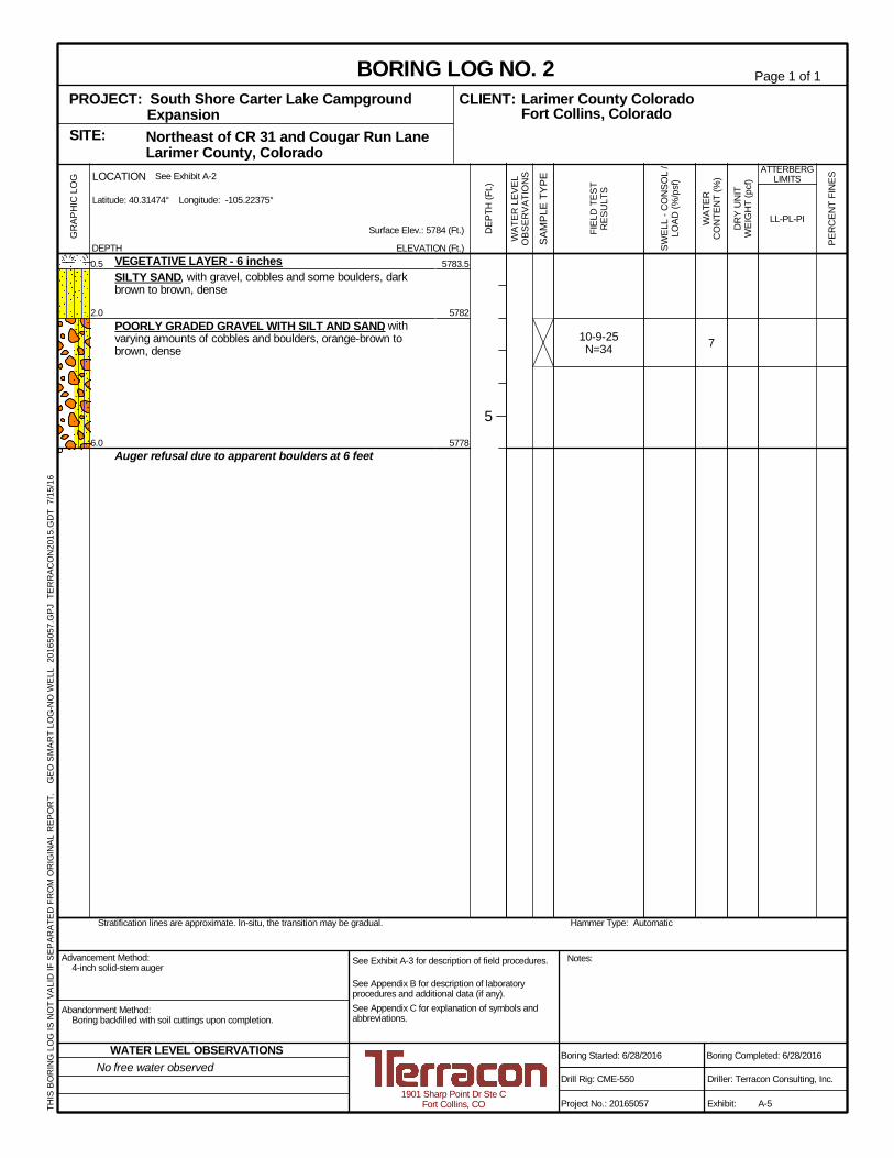
7
5783.5
5782
5778
10-9-25N=34
0.5
2.0
6.0
VEGETATIVE LAYER - 6 inchesSILTY SAND, with gravel, cobbles and some boulders, darkbrown to brown, dense
POORLY GRADED GRAVEL WITH SILT AND SAND, withvarying amounts of cobbles and boulders, orange-brown tobrown, dense
Auger refusal due to apparent boulders at 6 feet
Hammer Type: AutomaticStratification lines are approximate. In-situ, the transition may be gradual.
GR
APH
ICLO
G
THIS
BOR
ING
LOG
ISN
OT
VALI
DIF
SEPA
RAT
EDFR
OM
OR
IGIN
ALR
EPO
RT.
GEO
SMAR
TLO
G-N
OW
ELL
2016
5057
.GPJ
TER
RAC
ON
2015
.GD
T7/
15/1
6
Northeast of CR 31 and Cougar Run Lane Larimer County, ColoradoSITE:
Page 1 of 1
Advancement Method:4-inch solid-stem auger
Abandonment Method:Boring backfilled with soil cuttings upon completion.
1901 Sharp Point Dr Ste CFort Collins, CO
Notes:
Project No.: 20165057
Drill Rig: CME-550
Boring Started: 6/28/2016
BORING LOG NO. 2Larimer County ColoradoCLIENT:Fort Collins, Colorado
Driller: Terracon Consulting, Inc.
Boring Completed: 6/28/2016
Exhibit: A-5
See Exhibit A-3 for description of field procedures.
See Appendix B for description of laboratoryprocedures and additional data (if any).See Appendix C for explanation of symbols andabbreviations.
PROJECT: South Shore Carter Lake CampgroundExpansion
PER
CEN
TFI
NES
WAT
ERC
ON
TEN
T(%
)
DR
YU
NIT
WEI
GH
T(p
cf)
ATTERBERGLIMITS
LL-PL-PISurface Elev.: 5784 (Ft.)
ELEVATION (Ft.) SAM
PLE
TYPE
WAT
ERLE
VEL
OBS
ERVA
TIO
NS
DEP
TH(F
t.)
5
SWEL
L-C
ON
SOL
/LO
AD(%
/psf
)
FIEL
DTE
STR
ESU
LTS
DEPTH
LOCATION See Exhibit A-2
Latitude: 40.31474° Longitude: -105.22375°
No free water observedWATER LEVEL OBSERVATIONS
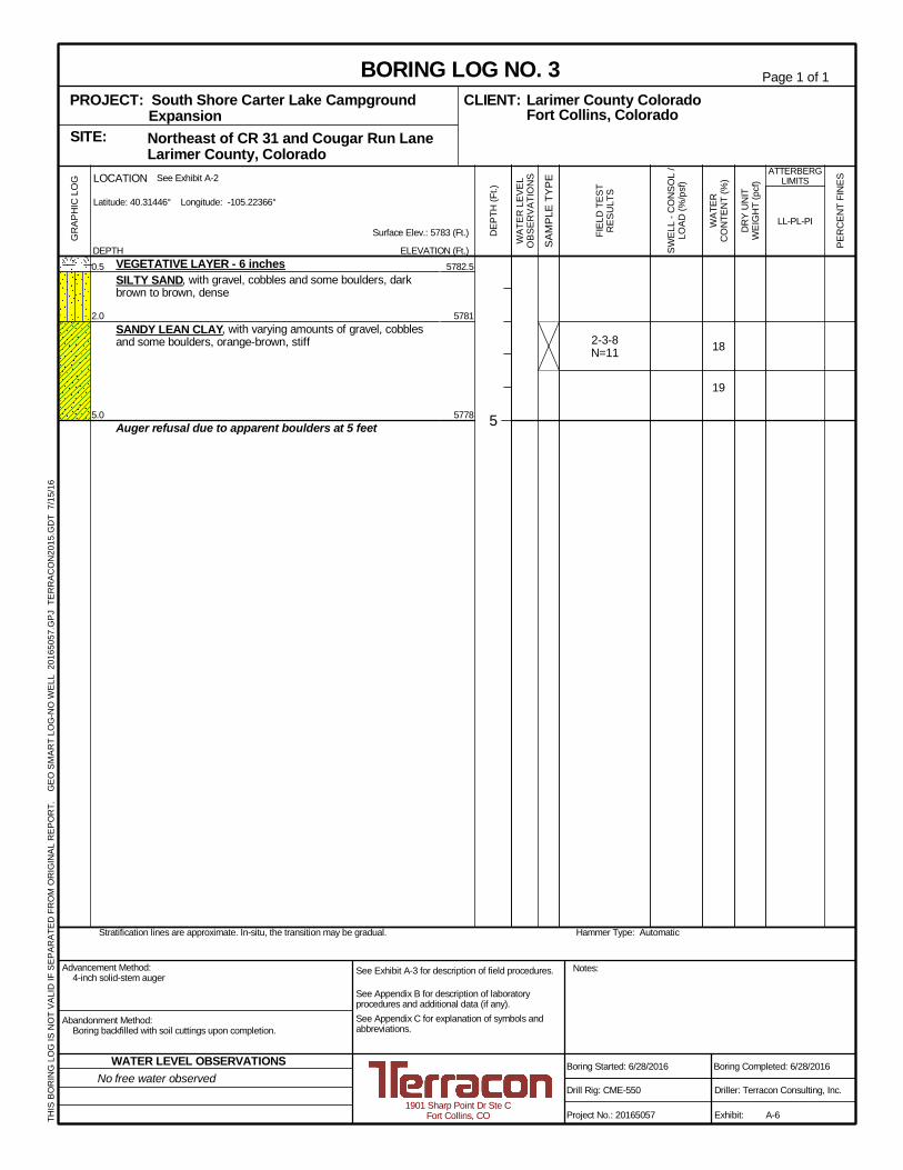
18
19
5782.5
5781
5778
2-3-8N=11
0.5
2.0
5.0
VEGETATIVE LAYER - 6 inchesSILTY SAND, with gravel, cobbles and some boulders, darkbrown to brown, dense
SANDY LEAN CLAY, with varying amounts of gravel, cobblesand some boulders, orange-brown, stiff
Auger refusal due to apparent boulders at 5 feet
Hammer Type: AutomaticStratification lines are approximate. In-situ, the transition may be gradual.
GR
APH
ICLO
G
THIS
BOR
ING
LOG
ISN
OT
VALI
DIF
SEPA
RAT
EDFR
OM
OR
IGIN
ALR
EPO
RT.
GEO
SMAR
TLO
G-N
OW
ELL
2016
5057
.GPJ
TER
RAC
ON
2015
.GD
T7/
15/1
6
Northeast of CR 31 and Cougar Run Lane Larimer County, ColoradoSITE:
Page 1 of 1
Advancement Method:4-inch solid-stem auger
Abandonment Method:Boring backfilled with soil cuttings upon completion.
1901 Sharp Point Dr Ste CFort Collins, CO
Notes:
Project No.: 20165057
Drill Rig: CME-550
Boring Started: 6/28/2016
BORING LOG NO. 3Larimer County ColoradoCLIENT:Fort Collins, Colorado
Driller: Terracon Consulting, Inc.
Boring Completed: 6/28/2016
Exhibit: A-6
See Exhibit A-3 for description of field procedures.
See Appendix B for description of laboratoryprocedures and additional data (if any).See Appendix C for explanation of symbols andabbreviations.
PROJECT: South Shore Carter Lake CampgroundExpansion
PER
CEN
TFI
NES
WAT
ERC
ON
TEN
T(%
)
DR
YU
NIT
WEI
GH
T(p
cf)
ATTERBERGLIMITS
LL-PL-PISurface Elev.: 5783 (Ft.)
ELEVATION (Ft.) SAM
PLE
TYPE
WAT
ERLE
VEL
OBS
ERVA
TIO
NS
DEP
TH(F
t.)
5
SWEL
L-C
ON
SOL
/LO
AD(%
/psf
)
FIEL
DTE
STR
ESU
LTS
DEPTH
LOCATION See Exhibit A-2
Latitude: 40.31446° Longitude: -105.22366°
No free water observedWATER LEVEL OBSERVATIONS
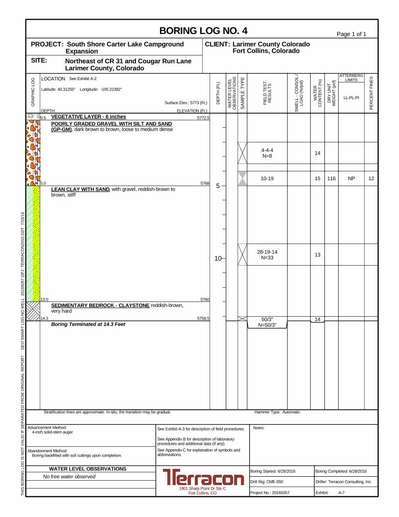
12
14
15
13
14
116 NP
5772.5
5768
5760
5758.5
4-4-4N=8
10-19
28-19-14N=33
50/3"N=50/3"
0.5
5.0
13.0
14.3
VEGETATIVE LAYER - 6 inchesPOORLY GRADED GRAVEL WITH SILT AND SAND(GP-GM), dark brown to brown, loose to medium dense
LEAN CLAY WITH SAND, with gravel, reddish-brown tobrown, stiff
SEDIMENTARY BEDROCK - CLAYSTONE, reddish-brown,very hard
Boring Terminated at 14.3 Feet
Hammer Type: AutomaticStratification lines are approximate. In-situ, the transition may be gradual.
GR
APH
ICLO
G
THIS
BOR
ING
LOG
ISN
OT
VALI
DIF
SEPA
RAT
EDFR
OM
OR
IGIN
ALR
EPO
RT.
GEO
SMAR
TLO
G-N
OW
ELL
2016
5057
.GPJ
TER
RAC
ON
2015
.GD
T7/
15/1
6
Northeast of CR 31 and Cougar Run Lane Larimer County, ColoradoSITE:
Page 1 of 1
Advancement Method:4-inch solid-stem auger
Abandonment Method:Boring backfilled with soil cuttings upon completion.
1901 Sharp Point Dr Ste CFort Collins, CO
Notes:
Project No.: 20165057
Drill Rig: CME-550
Boring Started: 6/28/2016
BORING LOG NO. 4Larimer County ColoradoCLIENT:Fort Collins, Colorado
Driller: Terracon Consulting, Inc.
Boring Completed: 6/28/2016
Exhibit: A-7
See Exhibit A-3 for description of field procedures.
See Appendix B for description of laboratoryprocedures and additional data (if any).See Appendix C for explanation of symbols andabbreviations.
PROJECT: South Shore Carter Lake CampgroundExpansion
PER
CEN
TFI
NES
WAT
ERC
ON
TEN
T(%
)
DR
YU
NIT
WEI
GH
T(p
cf)
ATTERBERGLIMITS
LL-PL-PISurface Elev.: 5773 (Ft.)
ELEVATION (Ft.) SAM
PLE
TYPE
WAT
ERLE
VEL
OBS
ERVA
TIO
NS
DEP
TH(F
t.)
5
10
SWEL
L-C
ON
SOL
/LO
AD(%
/psf
)
FIEL
DTE
STR
ESU
LTS
DEPTH
LOCATION See Exhibit A-2
Latitude: 40.31255° Longitude: -105.22382°
No free water observedWATER LEVEL OBSERVATIONS
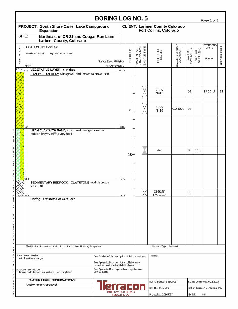
6416
16
10
8
115
38-20-18
5787.5
5781
5775
5773
0.0/1000
3-5-6N=11
3-5-5N=10
4-7
22-50/5"N=72/11"
0.5
7.0
13.0
14.9
VEGETATIVE LAYER - 6 inchesSANDY LEAN CLAY, with gravel, dark brown to brown, stiff
LEAN CLAY WITH SAND, with gravel, orange-brown toreddish-brown, stiff to very hard
SEDIMENTARY BEDROCK - CLAYSTONE, reddish-brown,very hard
Boring Terminated at 14.9 Feet
Hammer Type: AutomaticStratification lines are approximate. In-situ, the transition may be gradual.
GR
APH
ICLO
G
THIS
BOR
ING
LOG
ISN
OT
VALI
DIF
SEPA
RAT
EDFR
OM
OR
IGIN
ALR
EPO
RT.
GEO
SMAR
TLO
G-N
OW
ELL
2016
5057
.GPJ
TER
RAC
ON
2015
.GD
T7/
15/1
6
Northeast of CR 31 and Cougar Run Lane Larimer County, ColoradoSITE:
Page 1 of 1
Advancement Method:4-inch solid-stem auger
Abandonment Method:Boring backfilled with soil cuttings upon completion.
1901 Sharp Point Dr Ste CFort Collins, CO
Notes:
Project No.: 20165057
Drill Rig: CME-550
Boring Started: 6/28/2016
BORING LOG NO. 5Larimer County ColoradoCLIENT:Fort Collins, Colorado
Driller: Terracon Consulting, Inc.
Boring Completed: 6/28/2016
Exhibit: A-8
See Exhibit A-3 for description of field procedures.
See Appendix B for description of laboratoryprocedures and additional data (if any).See Appendix C for explanation of symbols andabbreviations.
PROJECT: South Shore Carter Lake CampgroundExpansion
PER
CEN
TFI
NES
WAT
ERC
ON
TEN
T(%
)
DR
YU
NIT
WEI
GH
T(p
cf)
ATTERBERGLIMITS
LL-PL-PISurface Elev.: 5788 (Ft.)
ELEVATION (Ft.) SAM
PLE
TYPE
WAT
ERLE
VEL
OBS
ERVA
TIO
NS
DEP
TH(F
t.)
5
10
SWEL
L-C
ON
SOL
/LO
AD(%
/psf
)
FIEL
DTE
STR
ESU
LTS
DEPTH
LOCATION See Exhibit A-2
Latitude: 40.31247° Longitude: -105.22196°
No free water observedWATER LEVEL OBSERVATIONS
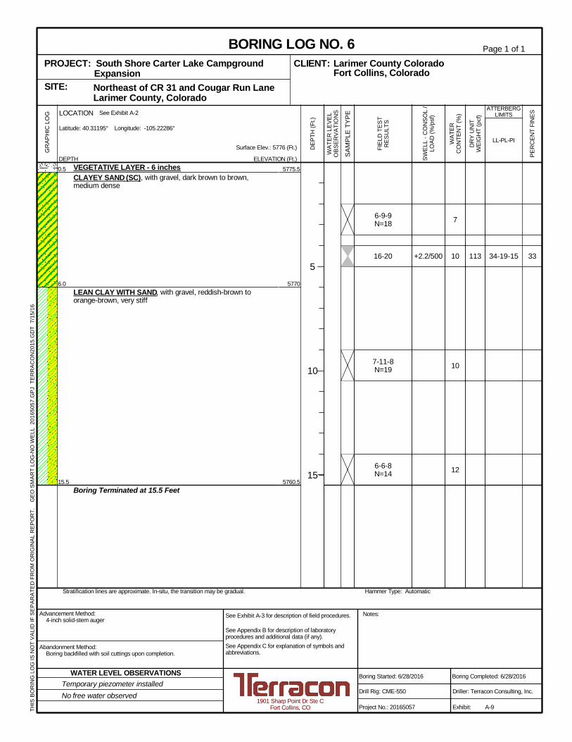
33
7
10
10
12
113 34-19-15
5775.5
5770
5760.5
+2.2/500
6-9-9N=18
16-20
7-11-8N=19
6-6-8N=14
0.5
6.0
15.5
VEGETATIVE LAYER - 6 inchesCLAYEY SAND (SC), with gravel, dark brown to brown,medium dense
LEAN CLAY WITH SAND, with gravel, reddish-brown toorange-brown, very stiff
Boring Terminated at 15.5 Feet
Hammer Type: AutomaticStratification lines are approximate. In-situ, the transition may be gradual.
GR
APH
ICLO
G
THIS
BOR
ING
LOG
ISN
OT
VALI
DIF
SEPA
RAT
EDFR
OM
OR
IGIN
ALR
EPO
RT.
GEO
SMAR
TLO
G-N
OW
ELL
2016
5057
.GPJ
TER
RAC
ON
2015
.GD
T7/
15/1
6
Northeast of CR 31 and Cougar Run Lane Larimer County, ColoradoSITE:
Page 1 of 1
Advancement Method:4-inch solid-stem auger
Abandonment Method:Boring backfilled with soil cuttings upon completion.
1901 Sharp Point Dr Ste CFort Collins, CO
Notes:
Project No.: 20165057
Drill Rig: CME-550
Boring Started: 6/28/2016
BORING LOG NO. 6Larimer County ColoradoCLIENT:Fort Collins, Colorado
Driller: Terracon Consulting, Inc.
Boring Completed: 6/28/2016
Exhibit: A-9
See Exhibit A-3 for description of field procedures.
See Appendix B for description of laboratoryprocedures and additional data (if any).See Appendix C for explanation of symbols andabbreviations.
PROJECT: South Shore Carter Lake CampgroundExpansion
PER
CEN
TFI
NES
WAT
ERC
ON
TEN
T(%
)
DR
YU
NIT
WEI
GH
T(p
cf)
ATTERBERGLIMITS
LL-PL-PISurface Elev.: 5776 (Ft.)
ELEVATION (Ft.) SAM
PLE
TYPE
WAT
ERLE
VEL
OBS
ERVA
TIO
NS
DEP
TH(F
t.)
5
10
15
SWEL
L-C
ON
SOL
/LO
AD(%
/psf
)
FIEL
DTE
STR
ESU
LTS
DEPTH
LOCATION See Exhibit A-2
Latitude: 40.31195° Longitude: -105.22286°
Temporary piezometer installedNo free water observed
WATER LEVEL OBSERVATIONS
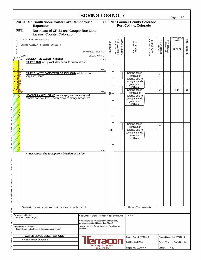
38
1
3
7
NP
5774.5
5773
5770
5762
Sample takenfrom auger
cuttings due tocaving of sands,
gravel andcobbles
Sample takenfrom auger
cuttings due tocaving of sands,
gravel andcobbles
Sample takenfrom auger
cuttings due tocaving of sands,
gravel andcobbles
0.5
2.0
5.0
13.0
VEGETATIVE LAYER - 6 inchesSILTY SAND, with gravel, dark brown to brown, dense
SILTY CLAYEY SAND WITH GRAVEL (SM), white to pink,very hard, dense
LEAN CLAY WITH SAND, with varying amounts of gravel,cobbles and boulders, reddish-brown to orange-brown, stiff
Auger refusal due to apparent boulders at 13 feet
Hammer Type: AutomaticStratification lines are approximate. In-situ, the transition may be gradual.
GR
APH
ICLO
G
THIS
BOR
ING
LOG
ISN
OT
VALI
DIF
SEPA
RAT
EDFR
OM
OR
IGIN
ALR
EPO
RT.
GEO
SMAR
TLO
G-N
OW
ELL
2016
5057
.GPJ
TER
RAC
ON
2015
.GD
T7/
15/1
6
Northeast of CR 31 and Cougar Run Lane Larimer County, ColoradoSITE:
Page 1 of 1
Advancement Method:4-inch solid-stem auger
Abandonment Method:Boring backfilled with soil cuttings upon completion.
1901 Sharp Point Dr Ste CFort Collins, CO
Notes:
Project No.: 20165057
Drill Rig: CME-550
Boring Started: 6/28/2016
BORING LOG NO. 7Larimer County ColoradoCLIENT:Fort Collins, Colorado
Driller: Terracon Consulting, Inc.
Boring Completed: 6/28/2016
Exhibit: A-10
See Exhibit A-3 for description of field procedures.
See Appendix B for description of laboratoryprocedures and additional data (if any).See Appendix C for explanation of symbols andabbreviations.
PROJECT: South Shore Carter Lake CampgroundExpansion
PER
CEN
TFI
NES
WAT
ERC
ON
TEN
T(%
)
DR
YU
NIT
WEI
GH
T(p
cf)
ATTERBERGLIMITS
LL-PL-PISurface Elev.: 5775 (Ft.)
ELEVATION (Ft.) SAM
PLE
TYPE
WAT
ERLE
VEL
OBS
ERVA
TIO
NS
DEP
TH(F
t.)
5
10
SWEL
L-C
ON
SOL
/LO
AD(%
/psf
)
FIEL
DTE
STR
ESU
LTS
DEPTH
LOCATION See Exhibit A-2
Latitude: 40.31157° Longitude: -105.22274°
No free water observedWATER LEVEL OBSERVATIONS
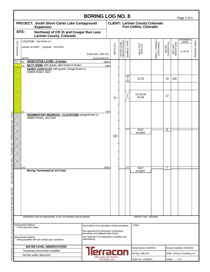
19
12
8
7
105
5800.5
5800
5794
5786.5
13-20
13-16-20N=36
50/3"N=50/3"
50/4"N=50/4"
0.5
1.0
7.0
14.3
VEGETATIVE LAYER - 6 inchesSILTY SAND, with gravel, dark brown to brownSANDY LEAN CLAY, with gravel, orange-brown toreddish-brown, hard
SEDIMENTARY BEDROCK - CLAYSTONE, orange-brown toreddish-brown, very hard
Boring Terminated at 14.3 Feet
Hammer Type: AutomaticStratification lines are approximate. In-situ, the transition may be gradual.
GR
APH
ICLO
G
THIS
BOR
ING
LOG
ISN
OT
VALI
DIF
SEPA
RAT
EDFR
OM
OR
IGIN
ALR
EPO
RT.
GEO
SMAR
TLO
G-N
OW
ELL
2016
5057
.GPJ
TER
RAC
ON
2015
.GD
T7/
15/1
6
Northeast of CR 31 and Cougar Run Lane Larimer County, ColoradoSITE:
Page 1 of 1
Advancement Method:4-inch solid-stem auger
Abandonment Method:Boring backfilled with soil cuttings upon completion.
1901 Sharp Point Dr Ste CFort Collins, CO
Notes:
Project No.: 20165057
Drill Rig: CME-550
Boring Started: 6/28/2016
BORING LOG NO. 8Larimer County ColoradoCLIENT:Fort Collins, Colorado
Driller: Terracon Consulting, Inc.
Boring Completed: 6/28/2016
Exhibit: A-11
See Exhibit A-3 for description of field procedures.
See Appendix B for description of laboratoryprocedures and additional data (if any).See Appendix C for explanation of symbols andabbreviations.
PROJECT: South Shore Carter Lake CampgroundExpansion
PER
CEN
TFI
NES
WAT
ERC
ON
TEN
T(%
)
DR
YU
NIT
WEI
GH
T(p
cf)
ATTERBERGLIMITS
LL-PL-PISurface Elev.: 5801 (Ft.)
ELEVATION (Ft.) SAM
PLE
TYPE
WAT
ERLE
VEL
OBS
ERVA
TIO
NS
DEP
TH(F
t.)
5
10
SWEL
L-C
ON
SOL
/LO
AD(%
/psf
)
FIEL
DTE
STR
ESU
LTS
DEPTH
LOCATION See Exhibit A-2
Latitude: 40.31065° Longitude: -105.22255°
Temporary piezometer installedNo free water observed
WATER LEVEL OBSERVATIONS
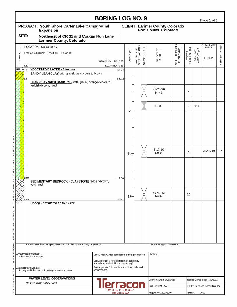
74
7
3
9
10
114
28-18-10
5804.5
5803.5
5792
5789.5
35-25-20N=45
19-32
6-17-19N=36
39-40-42N=82
0.5
1.5
13.0
15.5
VEGETATIVE LAYER - 6 inchesSANDY LEAN CLAY, with gravel, dark brown to brown
LEAN CLAY WITH SAND (CL), with gravel, orange-brown toreddish-brown, hard
SEDIMENTARY BEDROCK - CLAYSTONE, reddish-brown,very hard
Boring Terminated at 15.5 Feet
Hammer Type: AutomaticStratification lines are approximate. In-situ, the transition may be gradual.
GR
APH
ICLO
G
THIS
BOR
ING
LOG
ISN
OT
VALI
DIF
SEPA
RAT
EDFR
OM
OR
IGIN
ALR
EPO
RT.
GEO
SMAR
TLO
G-N
OW
ELL
2016
5057
.GPJ
TER
RAC
ON
2015
.GD
T7/
15/1
6
Northeast of CR 31 and Cougar Run Lane Larimer County, ColoradoSITE:
Page 1 of 1
Advancement Method:4-inch solid-stem auger
Abandonment Method:Boring backfilled with soil cuttings upon completion.
1901 Sharp Point Dr Ste CFort Collins, CO
Notes:
Project No.: 20165057
Drill Rig: CME-550
Boring Started: 6/28/2016
BORING LOG NO. 9Larimer County ColoradoCLIENT:Fort Collins, Colorado
Driller: Terracon Consulting, Inc.
Boring Completed: 6/28/2016
Exhibit: A-12
See Exhibit A-3 for description of field procedures.
See Appendix B for description of laboratoryprocedures and additional data (if any).See Appendix C for explanation of symbols andabbreviations.
PROJECT: South Shore Carter Lake CampgroundExpansion
PER
CEN
TFI
NES
WAT
ERC
ON
TEN
T(%
)
DR
YU
NIT
WEI
GH
T(p
cf)
ATTERBERGLIMITS
LL-PL-PISurface Elev.: 5805 (Ft.)
ELEVATION (Ft.) SAM
PLE
TYPE
WAT
ERLE
VEL
OBS
ERVA
TIO
NS
DEP
TH(F
t.)
5
10
15
SWEL
L-C
ON
SOL
/LO
AD(%
/psf
)
FIEL
DTE
STR
ESU
LTS
DEPTH
LOCATION See Exhibit A-2
Latitude: 40.31023° Longitude: -105.22315°
No free water observedWATER LEVEL OBSERVATIONS
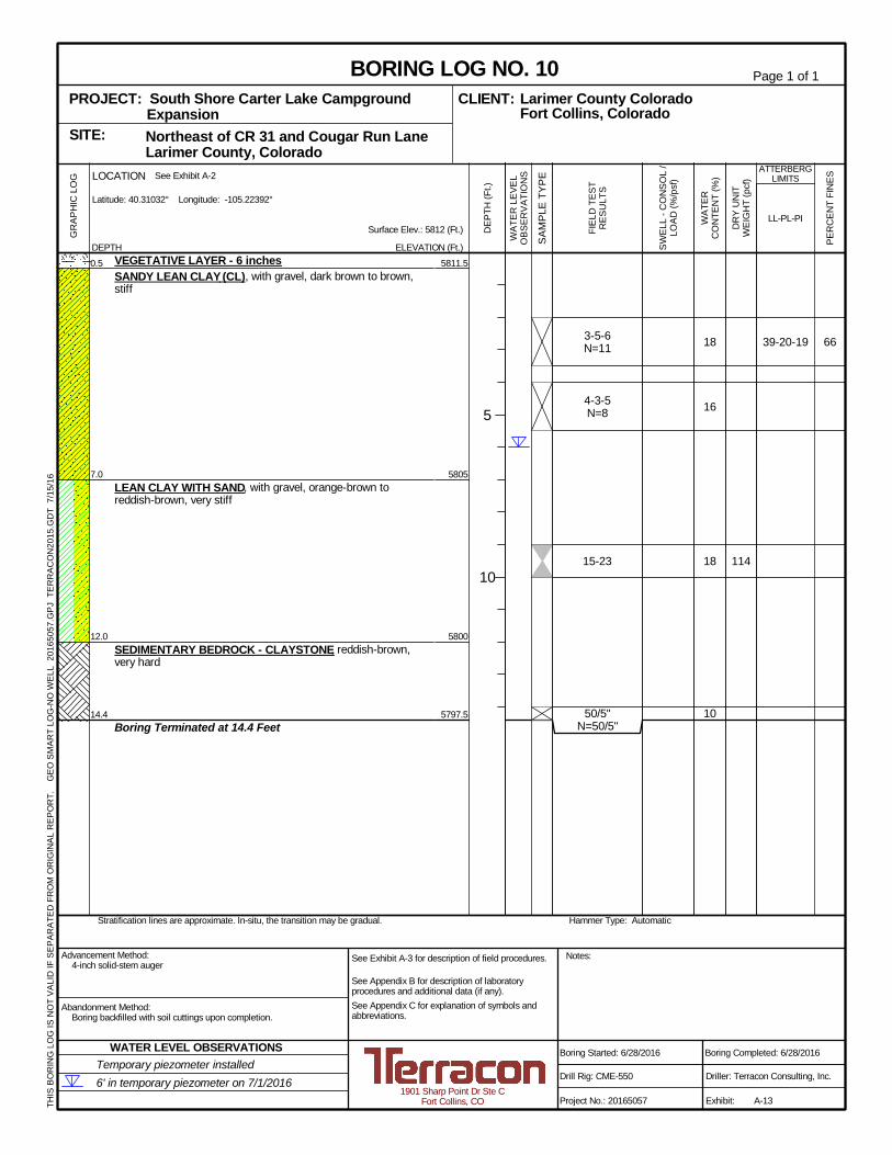
6618
16
18
10
114
39-20-19
5811.5
5805
5800
5797.5
3-5-6N=11
4-3-5N=8
15-23
50/5"N=50/5"
0.5
7.0
12.0
14.4
VEGETATIVE LAYER - 6 inchesSANDY LEAN CLAY (CL), with gravel, dark brown to brown,stiff
LEAN CLAY WITH SAND, with gravel, orange-brown toreddish-brown, very stiff
SEDIMENTARY BEDROCK - CLAYSTONE, reddish-brown,very hard
Boring Terminated at 14.4 Feet
Hammer Type: AutomaticStratification lines are approximate. In-situ, the transition may be gradual.
GR
APH
ICLO
G
THIS
BOR
ING
LOG
ISN
OT
VALI
DIF
SEPA
RAT
EDFR
OM
OR
IGIN
ALR
EPO
RT.
GEO
SMAR
TLO
G-N
OW
ELL
2016
5057
.GPJ
TER
RAC
ON
2015
.GD
T7/
15/1
6
Northeast of CR 31 and Cougar Run Lane Larimer County, ColoradoSITE:
Page 1 of 1
Advancement Method:4-inch solid-stem auger
Abandonment Method:Boring backfilled with soil cuttings upon completion.
1901 Sharp Point Dr Ste CFort Collins, CO
Notes:
Project No.: 20165057
Drill Rig: CME-550
Boring Started: 6/28/2016
BORING LOG NO. 10Larimer County ColoradoCLIENT:Fort Collins, Colorado
Driller: Terracon Consulting, Inc.
Boring Completed: 6/28/2016
Exhibit: A-13
See Exhibit A-3 for description of field procedures.
See Appendix B for description of laboratoryprocedures and additional data (if any).See Appendix C for explanation of symbols andabbreviations.
PROJECT: South Shore Carter Lake CampgroundExpansion
PER
CEN
TFI
NES
WAT
ERC
ON
TEN
T(%
)
DR
YU
NIT
WEI
GH
T(p
cf)
ATTERBERGLIMITS
LL-PL-PISurface Elev.: 5812 (Ft.)
ELEVATION (Ft.) SAM
PLE
TYPE
WAT
ERLE
VEL
OBS
ERVA
TIO
NS
DEP
TH(F
t.)
5
10
SWEL
L-C
ON
SOL
/LO
AD(%
/psf
)
FIEL
DTE
STR
ESU
LTS
DEPTH
LOCATION See Exhibit A-2
Latitude: 40.31032° Longitude: -105.22392°
Temporary piezometer installed6' in temporary piezometer on 7/1/2016
WATER LEVEL OBSERVATIONS
16
12
7
9
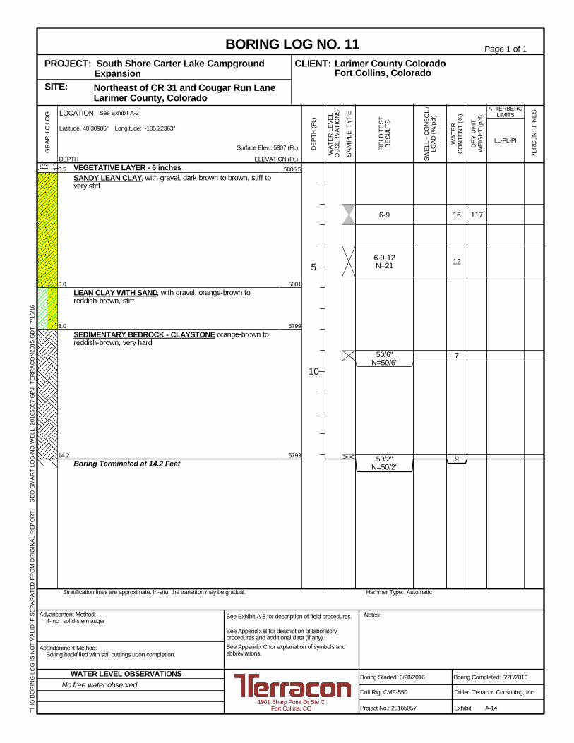
117
5806.5
5801
5799
5793
6-9
6-9-12N=21
50/6"N=50/6"
50/2"N=50/2"
0.5
6.0
8.0
14.2
VEGETATIVE LAYER - 6 inchesSANDY LEAN CLAY, with gravel, dark brown to brown, stiff tovery stiff
LEAN CLAY WITH SAND, with gravel, orange-brown toreddish-brown, stiff
SEDIMENTARY BEDROCK - CLAYSTONE, orange-brown toreddish-brown, very hard
Boring Terminated at 14.2 Feet
Hammer Type: AutomaticStratification lines are approximate. In-situ, the transition may be gradual.
GR
APH
ICLO
G
THIS
BOR
ING
LOG
ISN
OT
VALI
DIF
SEPA
RAT
EDFR
OM
OR
IGIN
ALR
EPO
RT.
GEO
SMAR
TLO
G-N
OW
ELL
2016
5057
.GPJ
TER
RAC
ON
2015
.GD
T7/
15/1
6
Northeast of CR 31 and Cougar Run Lane Larimer County, ColoradoSITE:
Page 1 of 1
Advancement Method:4-inch solid-stem auger
Abandonment Method:Boring backfilled with soil cuttings upon completion.
1901 Sharp Point Dr Ste CFort Collins, CO
Notes:
Project No.: 20165057
Drill Rig: CME-550
Boring Started: 6/28/2016
BORING LOG NO. 11Larimer County ColoradoCLIENT:Fort Collins, Colorado
Driller: Terracon Consulting, Inc.
Boring Completed: 6/28/2016
Exhibit: A-14
See Exhibit A-3 for description of field procedures.
See Appendix B for description of laboratoryprocedures and additional data (if any).See Appendix C for explanation of symbols andabbreviations.
PROJECT: South Shore Carter Lake CampgroundExpansion
PER
CEN
TFI
NES
WAT
ERC
ON
TEN
T(%
)
DR
YU
NIT
WEI
GH
T(p
cf)
ATTERBERGLIMITS
LL-PL-PISurface Elev.: 5807 (Ft.)
ELEVATION (Ft.) SAM
PLE
TYPE
WAT
ERLE
VEL
OBS
ERVA
TIO
NS
DEP
TH(F
t.)
5
10
SWEL
L-C
ON
SOL
/LO
AD(%
/psf
)
FIEL
DTE
STR
ESU
LTS
DEPTH
LOCATION See Exhibit A-2
Latitude: 40.30986° Longitude: -105.22363°
No free water observedWATER LEVEL OBSERVATIONS
618
10
10
8
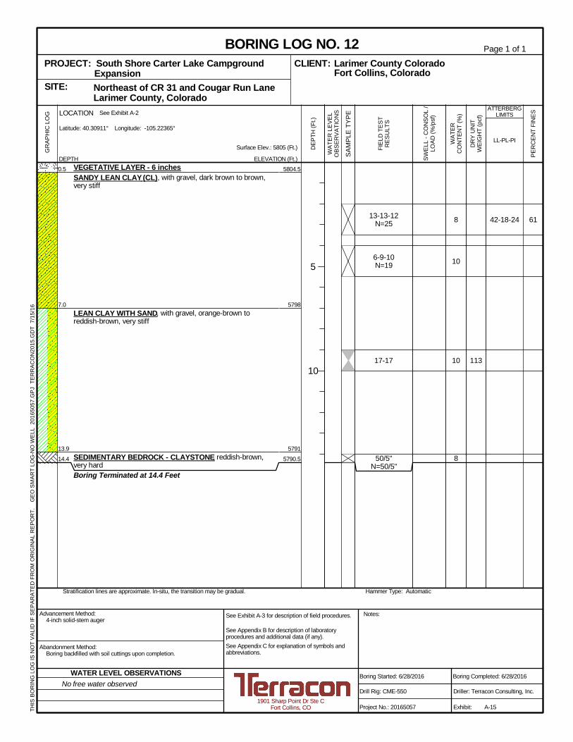
113
42-18-24
5804.5
5798
5791
5790.5
13-13-12N=25
6-9-10N=19
17-17
50/5"N=50/5"
0.5
7.0
13.9
14.4
VEGETATIVE LAYER - 6 inchesSANDY LEAN CLAY (CL), with gravel, dark brown to brown,very stiff
LEAN CLAY WITH SAND, with gravel, orange-brown toreddish-brown, very stiff
SEDIMENTARY BEDROCK - CLAYSTONE, reddish-brown,very hardBoring Terminated at 14.4 Feet
Hammer Type: AutomaticStratification lines are approximate. In-situ, the transition may be gradual.
GR
APH
ICLO
G
THIS
BOR
ING
LOG
ISN
OT
VALI
DIF
SEPA
RAT
EDFR
OM
OR
IGIN
ALR
EPO
RT.
GEO
SMAR
TLO
G-N
OW
ELL
2016
5057
.GPJ
TER
RAC
ON
2015
.GD
T7/
15/1
6
Northeast of CR 31 and Cougar Run Lane Larimer County, ColoradoSITE:
Page 1 of 1
Advancement Method:4-inch solid-stem auger
Abandonment Method:Boring backfilled with soil cuttings upon completion.
1901 Sharp Point Dr Ste CFort Collins, CO
Notes:
Project No.: 20165057
Drill Rig: CME-550
Boring Started: 6/28/2016
BORING LOG NO. 12Larimer County ColoradoCLIENT:Fort Collins, Colorado
Driller: Terracon Consulting, Inc.
Boring Completed: 6/28/2016
Exhibit: A-15
See Exhibit A-3 for description of field procedures.
See Appendix B for description of laboratoryprocedures and additional data (if any).See Appendix C for explanation of symbols andabbreviations.
PROJECT: South Shore Carter Lake CampgroundExpansion
PER
CEN
TFI
NES
WAT
ERC
ON
TEN
T(%
)
DR
YU
NIT
WEI
GH
T(p
cf)
ATTERBERGLIMITS
LL-PL-PISurface Elev.: 5805 (Ft.)
ELEVATION (Ft.) SAM
PLE
TYPE
WAT
ERLE
VEL
OBS
ERVA
TIO
NS
DEP
TH(F
t.)
5
10
SWEL
L-C
ON
SOL
/LO
AD(%
/psf
)
FIEL
DTE
STR
ESU
LTS
DEPTH
LOCATION See Exhibit A-2
Latitude: 40.30911° Longitude: -105.22365°
No free water observedWATER LEVEL OBSERVATIONS
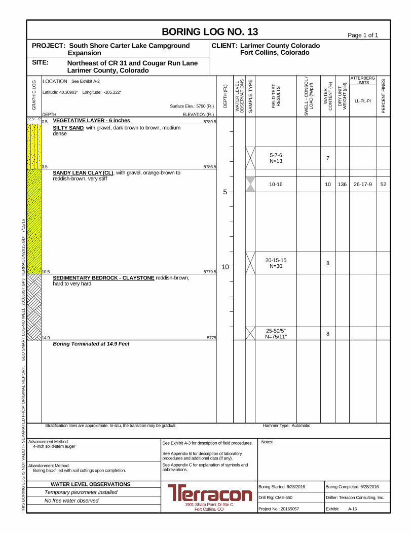
52
7
10
8
8
136 26-17-9
5789.5
5786.5
5779.5
5775
5-7-6N=13
10-16
20-15-15N=30
25-50/5"N=75/11"
0.5
3.5
10.5
14.9
VEGETATIVE LAYER - 6 inchesSILTY SAND, with gravel, dark brown to brown, mediumdense
SANDY LEAN CLAY (CL), with gravel, orange-brown toreddish-brown, very stiff
SEDIMENTARY BEDROCK - CLAYSTONE, reddish-brown,hard to very hard
Boring Terminated at 14.9 Feet
Hammer Type: AutomaticStratification lines are approximate. In-situ, the transition may be gradual.
GR
APH
ICLO
G
THIS
BOR
ING
LOG
ISN
OT
VALI
DIF
SEPA
RAT
EDFR
OM
OR
IGIN
ALR
EPO
RT.
GEO
SMAR
TLO
G-N
OW
ELL
2016
5057
.GPJ
TER
RAC
ON
2015
.GD
T7/
15/1
6
Northeast of CR 31 and Cougar Run Lane Larimer County, ColoradoSITE:
Page 1 of 1
Advancement Method:4-inch solid-stem auger
Abandonment Method:Boring backfilled with soil cuttings upon completion.
1901 Sharp Point Dr Ste CFort Collins, CO
Notes:
Project No.: 20165057
Drill Rig: CME-550
Boring Started: 6/28/2016
BORING LOG NO. 13Larimer County ColoradoCLIENT:Fort Collins, Colorado
Driller: Terracon Consulting, Inc.
Boring Completed: 6/28/2016
Exhibit: A-16
See Exhibit A-3 for description of field procedures.
See Appendix B for description of laboratoryprocedures and additional data (if any).See Appendix C for explanation of symbols andabbreviations.
PROJECT: South Shore Carter Lake CampgroundExpansion
PER
CEN
TFI
NES
WAT
ERC
ON
TEN
T(%
)
DR
YU
NIT
WEI
GH
T(p
cf)
ATTERBERGLIMITS
LL-PL-PISurface Elev.: 5790 (Ft.)
ELEVATION (Ft.) SAM
PLE
TYPE
WAT
ERLE
VEL
OBS
ERVA
TIO
NS
DEP
TH(F
t.)
5
10
SWEL
L-C
ON
SOL
/LO
AD(%
/psf
)
FIEL
DTE
STR
ESU
LTS
DEPTH
LOCATION See Exhibit A-2
Latitude: 40.30903° Longitude: -105.222°
Temporary piezometer installedNo free water observed
WATER LEVEL OBSERVATIONS
APPENDIX B
LABORATORY TESTING
Geotechnical Engineering Report South Shore Carter Lake Campground Expansion ■ Larimer County, Colorado July 15, 2016 ■ Terracon Project No. 20165057
Responsive ■ Resourceful ■ Reliable Exhibit B-1
Laboratory Testing Description
The soil and bedrock samples retrieved during the field exploration were returned to the laboratory
for observation by the project geotechnical engineer. At that time, the field descriptions were
reviewed and an applicable laboratory testing program was formulated to determine engineering
properties of the subsurface materials.
Laboratory tests were conducted on selected soil and bedrock samples. The results of these
tests are presented on the boring logs and in this appendix. The test results were used for the
geotechnical engineering analyses, and the development of foundation and earthwork
recommendations. The laboratory tests were performed in general accordance with applicable
locally accepted standards. Soil samples were classified in general accordance with the Unified
Soil Classification System described in Appendix C. Rock samples were visually classified in
general accordance with the description of rock properties presented in Appendix C. Procedural
standards noted in this report are for reference to methodology in general. In some cases variations
to methods are applied as a result of local practice or professional judgment.
Water content Plasticity index
Grain-size distribution
Consolidation/swell
Dry density
Water-soluble sulfate content
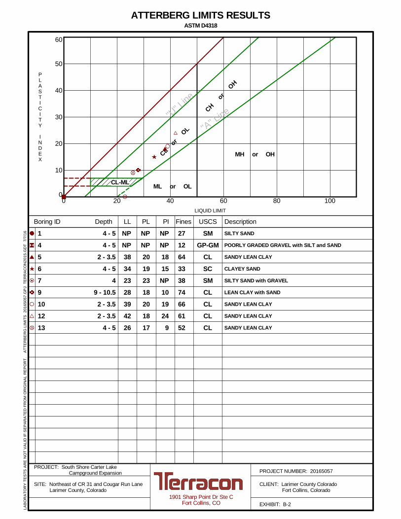
0
10
20
30
40
50
60
0 20 40 60 80 100
CHor
OH
CLor
OL
ML or OL
MH or OH
PL PIBoring ID Depth Description
SILTY SAND
POORLY GRADED GRAVEL with SILT and SAND
SANDY LEAN CLAY
CLAYEY SAND
SILTY SAND with GRAVEL
LEAN CLAY with SAND
SANDY LEAN CLAY
SANDY LEAN CLAY
SANDY LEAN CLAY
SMGP-GM
CLSCSMCLCLCLCL
Fines
PLASTICITY
INDEX
LIQUID LIMIT
"U" Lin
e
"A" Line
NPNP38342328394226
NPNP20192318201817
NPNP1815NP1019249
271264333874666152
LL USCS
145679101213
ATTERBERG LIMITS RESULTSASTM D4318
4 - 54 - 5
2 - 3.54 - 5
49 - 10.52 - 3.52 - 3.5
4 - 5
PROJECT NUMBER: 20165057PROJECT: South Shore Carter Lake
Campground Expansion
SITE: Northeast of CR 31 and Cougar Run Lane Larimer County, Colorado
CLIENT: Larimer County Colorado Fort Collins, Colorado
EXHIBIT: B-21901 Sharp Point Dr Ste C
Fort Collins, CO
LABO
RAT
OR
YTE
STS
ARE
NO
TVA
LID
IFSE
PAR
ATED
FRO
MO
RIG
INAL
REP
OR
T.AT
TER
BER
GLI
MIT
S20
1650
57.G
PJTE
RR
ACO
N20
15.G
DT
7/7/
16
CL-ML
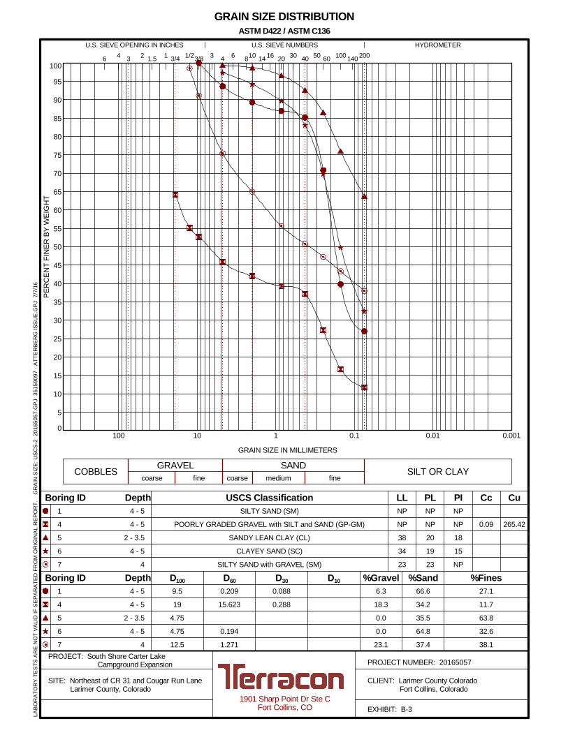
0
5
10
15
20
25
30
35
40
45
50
55
60
65
70
75
80
85
90
95
100
0.0010.010.1110100
1
4
5
6
7
NP
NP
38
34
23
0.088
0.288
0.209
15.623
0.194
1.271
9.5
19
4.75
4.75
12.5
6 16 20 30 40 501.5 2006 810
6.3
18.3
0.0
0.0
23.1
14
27.1
11.7
63.8
32.6
38.1
%Fines
LL PL PI
41 3/4 1/2 60
fine
1
4
5
6
7
265.42
GRAIN SIZE IN MILLIMETERS
PER
CEN
TFI
NER
BYW
EIG
HT
coarse fine
HYDROMETERU.S. SIEVE OPENING IN INCHES U.S. SIEVE NUMBERS
NP
NP
20
19
23
NP
NP
18
15
NP
0.09
D100
Cc Cu
SILT OR CLAY
4
%Sand%GravelD30 D10
4 - 5
4 - 5
2 - 3.5
4 - 5
4
3/8 3 100 1403 2
COBBLES GRAVEL SAND
USCS Classification
66.6
34.2
35.5
64.8
37.4
D60
coarse medium
Boring ID Depth
Boring ID Depth
GRAIN SIZE DISTRIBUTION
4 - 5
4 - 5
2 - 3.5
4 - 5
4
SILTY SAND (SM)
POORLY GRADED GRAVEL with SILT and SAND (GP-GM)
SANDY LEAN CLAY (CL)
CLAYEY SAND (SC)
SILTY SAND with GRAVEL (SM)
ASTM D422 / ASTM C136
PROJECT NUMBER: 20165057PROJECT: South Shore Carter Lake
Campground Expansion
SITE: Northeast of CR 31 and Cougar Run Lane Larimer County, Colorado
CLIENT: Larimer County Colorado Fort Collins, Colorado
EXHIBIT: B-31901 Sharp Point Dr Ste C
Fort Collins, CO
LABO
RAT
OR
YTE
STS
ARE
NO
TVA
LID
IFSE
PAR
ATED
FRO
MO
RIG
INAL
REP
OR
T.G
RAI
NSI
ZE:U
SCS-
220
1650
57.G
PJ35
1590
97-A
TTER
BER
GIS
SUE.
GPJ
7/7/
16
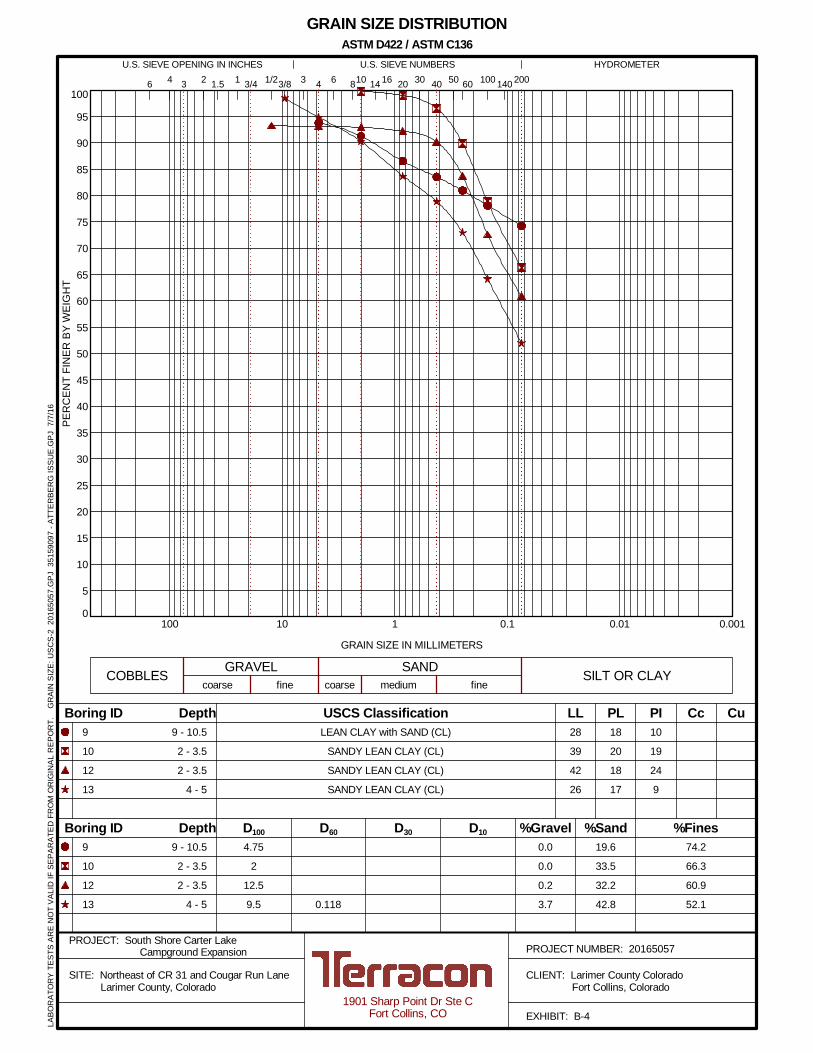
0
5
10
15
20
25
30
35
40
45
50
55
60
65
70
75
80
85
90
95
100
0.0010.010.1110100
9
10
12
13
28
39
42
26
0.118
4.75
2
12.5
9.5
6 16 20 30 40 501.5 2006 810
0.0
0.0
0.2
3.7
14
74.2
66.3
60.9
52.1
%Fines
LL PL PI
41 3/4 1/2 60
fine
9
10
12
13
GRAIN SIZE IN MILLIMETERS
PER
CEN
TFI
NER
BYW
EIG
HT
coarse fine
HYDROMETERU.S. SIEVE OPENING IN INCHES U.S. SIEVE NUMBERS
18
20
18
17
10
19
24
9
D100
Cc Cu
SILT OR CLAY
4
%Sand%GravelD30 D10
9 - 10.5
2 - 3.5
2 - 3.5
4 - 5
3/8 3 100 1403 2
COBBLES GRAVEL SAND
USCS Classification
19.6
33.5
32.2
42.8
D60
coarse medium
Boring ID Depth
Boring ID Depth
GRAIN SIZE DISTRIBUTION
9 - 10.5
2 - 3.5
2 - 3.5
4 - 5
LEAN CLAY with SAND (CL)
SANDY LEAN CLAY (CL)
SANDY LEAN CLAY (CL)
SANDY LEAN CLAY (CL)
ASTM D422 / ASTM C136
PROJECT NUMBER: 20165057PROJECT: South Shore Carter Lake
Campground Expansion
SITE: Northeast of CR 31 and Cougar Run Lane Larimer County, Colorado
CLIENT: Larimer County Colorado Fort Collins, Colorado
EXHIBIT: B-41901 Sharp Point Dr Ste C
Fort Collins, CO
LABO
RAT
OR
YTE
STS
ARE
NO
TVA
LID
IFSE
PAR
ATED
FRO
MO
RIG
INAL
REP
OR
T.G
RAI
NSI
ZE:U
SCS-
220
1650
57.G
PJ35
1590
97-A
TTER
BER
GIS
SUE.
GPJ
7/7/
16
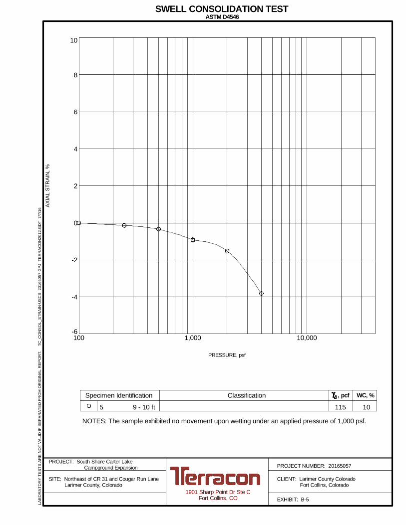
-6
-4
-2
0
2
4
6
8
10
100 1,000 10,000
AXIA
LST
RAI
N,%
PRESSURE, psf
SWELL CONSOLIDATION TESTASTM D4546
NOTES: The sample exhibited no movement upon wetting under an applied pressure of 1,000 psf.
Specimen Identification Classification , pcf
1155 10
WC, %
9 - 10 ft
PROJECT NUMBER: 20165057PROJECT: South Shore Carter Lake
Campground Expansion
SITE: Northeast of CR 31 and Cougar Run Lane Larimer County, Colorado
CLIENT: Larimer County Colorado Fort Collins, Colorado
EXHIBIT: B-51901 Sharp Point Dr Ste C
Fort Collins, CO
LABO
RAT
OR
YTE
STS
ARE
NO
TVA
LID
IFSE
PAR
ATED
FRO
MO
RIG
INAL
REP
OR
T.TC
_CO
NSO
L_ST
RAI
N-U
SCS
2016
5057
.GPJ
TER
RAC
ON
2012
.GD
T7/
7/16
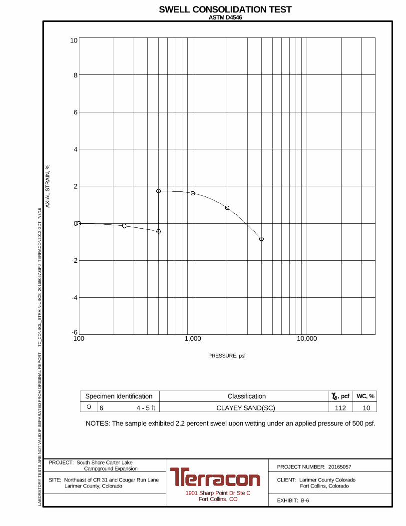
-6
-4
-2
0
2
4
6
8
10
100 1,000 10,000
AXIA
LST
RAI
N,%
PRESSURE, psf
SWELL CONSOLIDATION TESTASTM D4546
NOTES: The sample exhibited 2.2 percent sweel upon wetting under an applied pressure of 500 psf.
Specimen Identification Classification , pcf
1126 10
WC, %
CLAYEY SAND(SC)4 - 5 ft
PROJECT NUMBER: 20165057PROJECT: South Shore Carter Lake
Campground Expansion
SITE: Northeast of CR 31 and Cougar Run Lane Larimer County, Colorado
CLIENT: Larimer County Colorado Fort Collins, Colorado
EXHIBIT: B-61901 Sharp Point Dr Ste C
Fort Collins, CO
LABO
RAT
OR
YTE
STS
ARE
NO
TVA
LID
IFSE
PAR
ATED
FRO
MO
RIG
INAL
REP
OR
T.TC
_CO
NSO
L_ST
RAI
N-U
SCS
2016
5057
.GPJ
TER
RAC
ON
2012
.GD
T7/
7/16
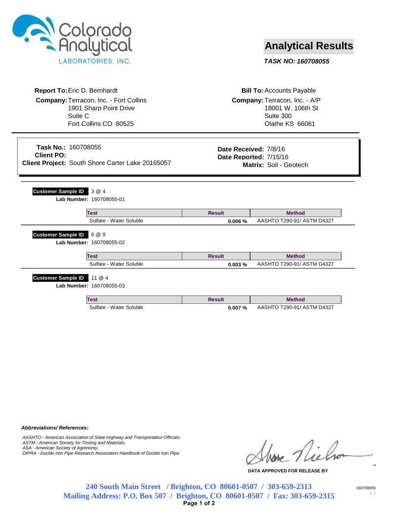
160708055TASK NO:
Analytical Results
Terracon, Inc. - Fort CollinsEric D. Bernhardt
Company:Report To:
Company:Bill To:
1901 Sharp Point DriveSuite CFort Collins CO 80525
Accounts PayableTerracon, Inc. - A/P18001 W. 106th StSuite 300Olathe KS 66061
South Shore Carter Lake 20165057Date Reported: 7/15/16
Task No.: 160708055
Matrix: Soil - Geotech
Date Received: 7/8/16
Client Project:Client PO:
3 @ 4Customer Sample ID
Test Method
160708055-01Lab Number:
ResultSulfate - Water Soluble AASHTO T290-91/ ASTM D4327 0.006 %
6 @ 9Customer Sample ID
Test Method
160708055-02Lab Number:
ResultSulfate - Water Soluble AASHTO T290-91/ ASTM D4327 0.003 %
11 @ 4Customer Sample ID
Test Method
160708055-03Lab Number:
ResultSulfate - Water Soluble AASHTO T290-91/ ASTM D4327 0.007 %
240 South Main Street / Brighton, CO 80601-0507 / 303-659-2313Mailing Address: P.O. Box 507 / Brighton, CO 80601-0507 / Fax: 303-659-2315
DATA APPROVED FOR RELEASE BY
Abbreviations/ References:
160708055
AASHTO - American Association of State Highway and Transportation Officials. ASTM - American Society for Testing and Materials. ASA - American Society of Agronomy. DIPRA - Ductile Iron Pipe Research Association Handbook of Ductile Iron Pipe.
APPENDIX C
SUPPORTING DOCUMENTS
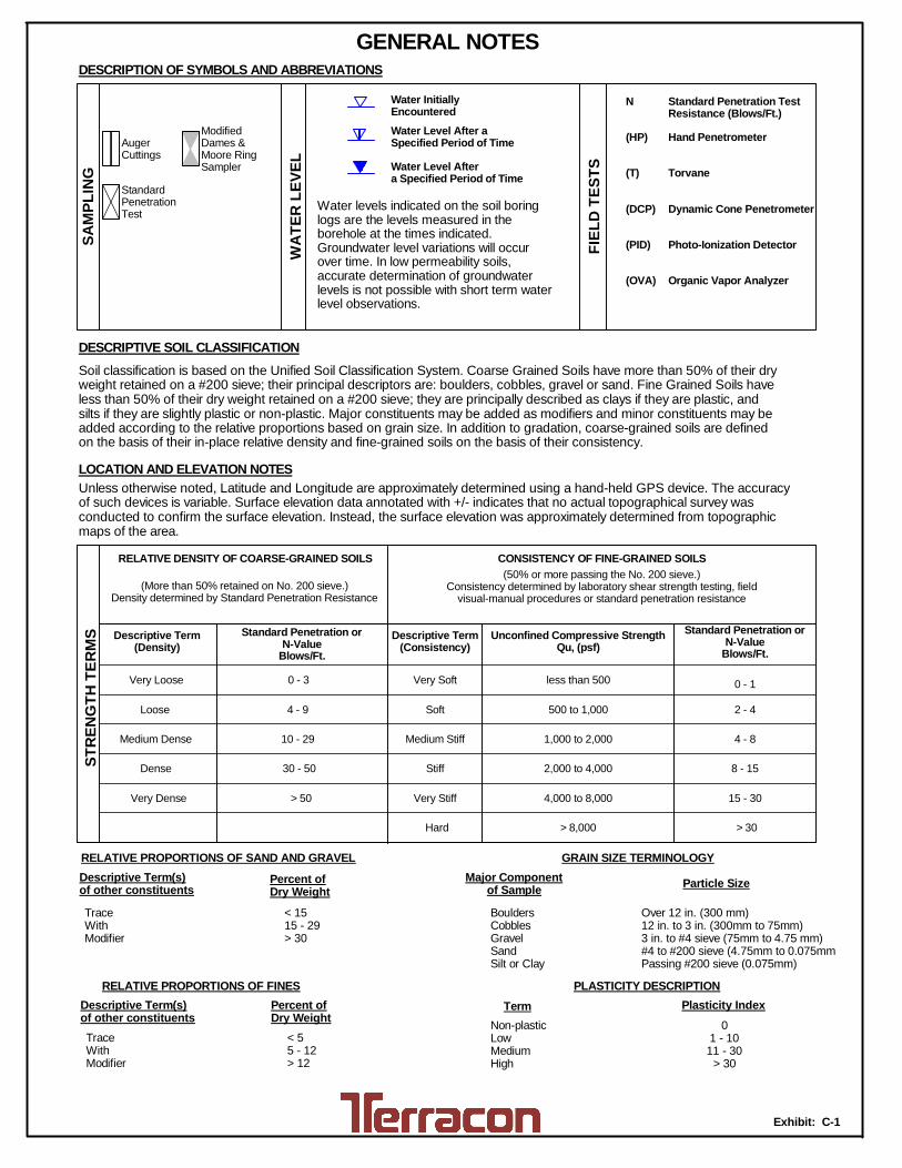
Exhibit: C-1
Unconfined Compressive StrengthQu, (psf)
500 to 1,000
2,000 to 4,000
4,000 to 8,000
1,000 to 2,000
less than 500
> 8,000
Non-plasticLowMediumHigh
DESCRIPTION OF SYMBOLS AND ABBREVIATIONSSA
MPL
ING
WAT
ERLE
VEL
FIEL
DTE
STS
GENERAL NOTES
Over 12 in. (300 mm)12 in. to 3 in. (300mm to 75mm)3 in. to #4 sieve (75mm to 4.75 mm)#4 to #200 sieve (4.75mm to 0.075mmPassing #200 sieve (0.075mm)
Particle Size
< 55 - 12> 12
Percent ofDry Weight
Descriptive Term(s)of other constituents
RELATIVE PROPORTIONS OF FINES
01 - 1011 - 30
> 30
Plasticity Index
Soil classification is based on the Unified Soil Classification System. Coarse Grained Soils have more than 50% of their dryweight retained on a #200 sieve; their principal descriptors are: boulders, cobbles, gravel or sand. Fine Grained Soils haveless than 50% of their dry weight retained on a #200 sieve; they are principally described as clays if they are plastic, andsilts if they are slightly plastic or non-plastic. Major constituents may be added as modifiers and minor constituents may beadded according to the relative proportions based on grain size. In addition to gradation, coarse-grained soils are definedon the basis of their in-place relative density and fine-grained soils on the basis of their consistency.
LOCATION AND ELEVATION NOTES
Percent ofDry Weight
Major Componentof Sample
TraceWithModifier
RELATIVE PROPORTIONS OF SAND AND GRAVEL GRAIN SIZE TERMINOLOGY
TraceWithModifier
DESCRIPTIVE SOIL CLASSIFICATION
BouldersCobblesGravelSandSilt or Clay
Descriptive Term(s)of other constituents
N
(HP)
(T)
(DCP)
(PID)
(OVA)
< 1515 - 29> 30
TermPLASTICITY DESCRIPTION
Water levels indicated on the soil boringlogs are the levels measured in theborehole at the times indicated.Groundwater level variations will occurover time. In low permeability soils,accurate determination of groundwaterlevels is not possible with short term waterlevel observations.
Water Level Aftera Specified Period of Time
Water Level After aSpecified Period of Time
Water InitiallyEncountered
AugerCuttings
ModifiedDames &Moore RingSampler
StandardPenetrationTest
Unless otherwise noted, Latitude and Longitude are approximately determined using a hand-held GPS device. The accuracyof such devices is variable. Surface elevation data annotated with +/- indicates that no actual topographical survey wasconducted to confirm the surface elevation. Instead, the surface elevation was approximately determined from topographicmaps of the area.
Standard Penetration TestResistance (Blows/Ft.)
Hand Penetrometer
Torvane
Dynamic Cone Penetrometer
Photo-Ionization Detector
Organic Vapor Analyzer
STRE
NGTH
TERM
S Standard Penetration orN-Value
Blows/Ft.
Descriptive Term(Consistency)
Descriptive Term(Density)
CONSISTENCY OF FINE-GRAINED SOILS(50% or more passing the No. 200 sieve.)
Consistency determined by laboratory shear strength testing, fieldvisual-manual procedures or standard penetration resistance
Standard Penetration orN-Value
Blows/Ft.
(More than 50% retained on No. 200 sieve.)Density determined by Standard Penetration Resistance
RELATIVE DENSITY OF COARSE-GRAINED SOILS
Hard > 30
> 50 15 - 30Very Stiff
Stiff
Medium Stiff
Very Soft 0 - 1
Medium Dense
SoftLoose
Very Dense
8 - 1530 - 50Dense
4 - 810 - 29
2 - 44 - 9
Very Loose 0 - 3
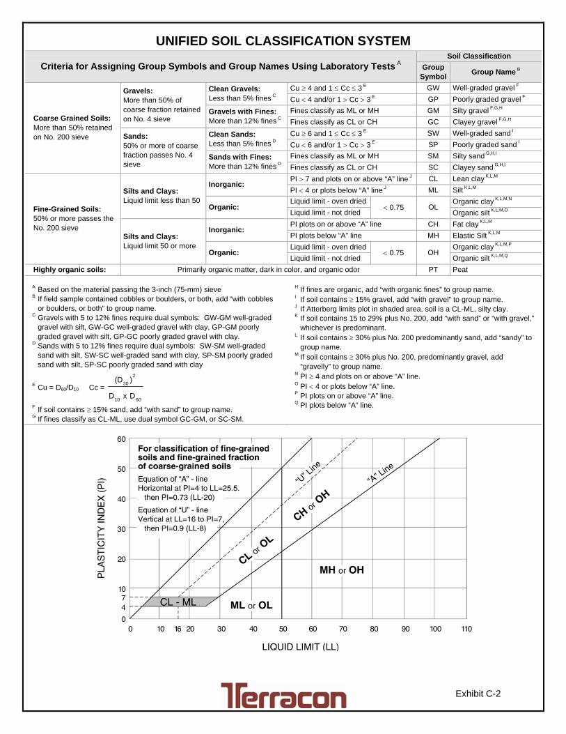
UNIFIED SOIL CLASSIFICATION SYSTEM
Exhibit C-2
Criteria for Assigning Group Symbols and Group Names Using Laboratory Tests A Soil Classification
Group Symbol
Group Name B
Coarse Grained Soils: More than 50% retained on No. 200 sieve
Gravels: More than 50% of coarse fraction retained on No. 4 sieve
Clean Gravels: Less than 5% fines C
Cu 4 and 1 Cc 3 E GW Well-graded gravel F
Cu 4 and/or 1 Cc 3 E GP Poorly graded gravel F
Gravels with Fines: More than 12% fines C
Fines classify as ML or MH GM Silty gravel F,G,H
Fines classify as CL or CH GC Clayey gravel F,G,H
Sands: 50% or more of coarse fraction passes No. 4 sieve
Clean Sands: Less than 5% fines D
Cu 6 and 1 Cc 3 E SW Well-graded sand I
Cu 6 and/or 1 Cc 3 E SP Poorly graded sand I
Sands with Fines: More than 12% fines D
Fines classify as ML or MH SM Silty sand G,H,I
Fines classify as CL or CH SC Clayey sand G,H,I
Fine-Grained Soils: 50% or more passes the No. 200 sieve
Silts and Clays: Liquid limit less than 50
Inorganic: PI 7 and plots on or above “A” line J CL Lean clay K,L,M
PI 4 or plots below “A” line J ML Silt K,L,M
Organic: Liquid limit - oven dried
0.75 OL Organic clay K,L,M,N
Liquid limit - not dried Organic silt K,L,M,O
Silts and Clays: Liquid limit 50 or more
Inorganic: PI plots on or above “A” line CH Fat clay K,L,M
PI plots below “A” line MH Elastic Silt K,L,M
Organic: Liquid limit - oven dried
0.75 OH Organic clay K,L,M,P
Liquid limit - not dried Organic silt K,L,M,Q
Highly organic soils: Primarily organic matter, dark in color, and organic odor PT Peat
A Based on the material passing the 3-inch (75-mm) sieve B If field sample contained cobbles or boulders, or both, add “with cobbles
or boulders, or both” to group name. C Gravels with 5 to 12% fines require dual symbols: GW-GM well-graded
gravel with silt, GW-GC well-graded gravel with clay, GP-GM poorly graded gravel with silt, GP-GC poorly graded gravel with clay.
D Sands with 5 to 12% fines require dual symbols: SW-SM well-graded sand with silt, SW-SC well-graded sand with clay, SP-SM poorly graded sand with silt, SP-SC poorly graded sand with clay
E Cu = D60/D10 Cc =
6010
2
30
DxD
)(D
F If soil contains 15% sand, add “with sand” to group name. G If fines classify as CL-ML, use dual symbol GC-GM, or SC-SM.
H If fines are organic, add “with organic fines” to group name. I If soil contains 15% gravel, add “with gravel” to group name. J If Atterberg limits plot in shaded area, soil is a CL-ML, silty clay. K If soil contains 15 to 29% plus No. 200, add “with sand” or “with gravel,”
whichever is predominant. L If soil contains 30% plus No. 200 predominantly sand, add “sandy” to
group name. M If soil contains 30% plus No. 200, predominantly gravel, add
“gravelly” to group name. N PI 4 and plots on or above “A” line. O PI 4 or plots below “A” line. P PI plots on or above “A” line. Q PI plots below “A” line.
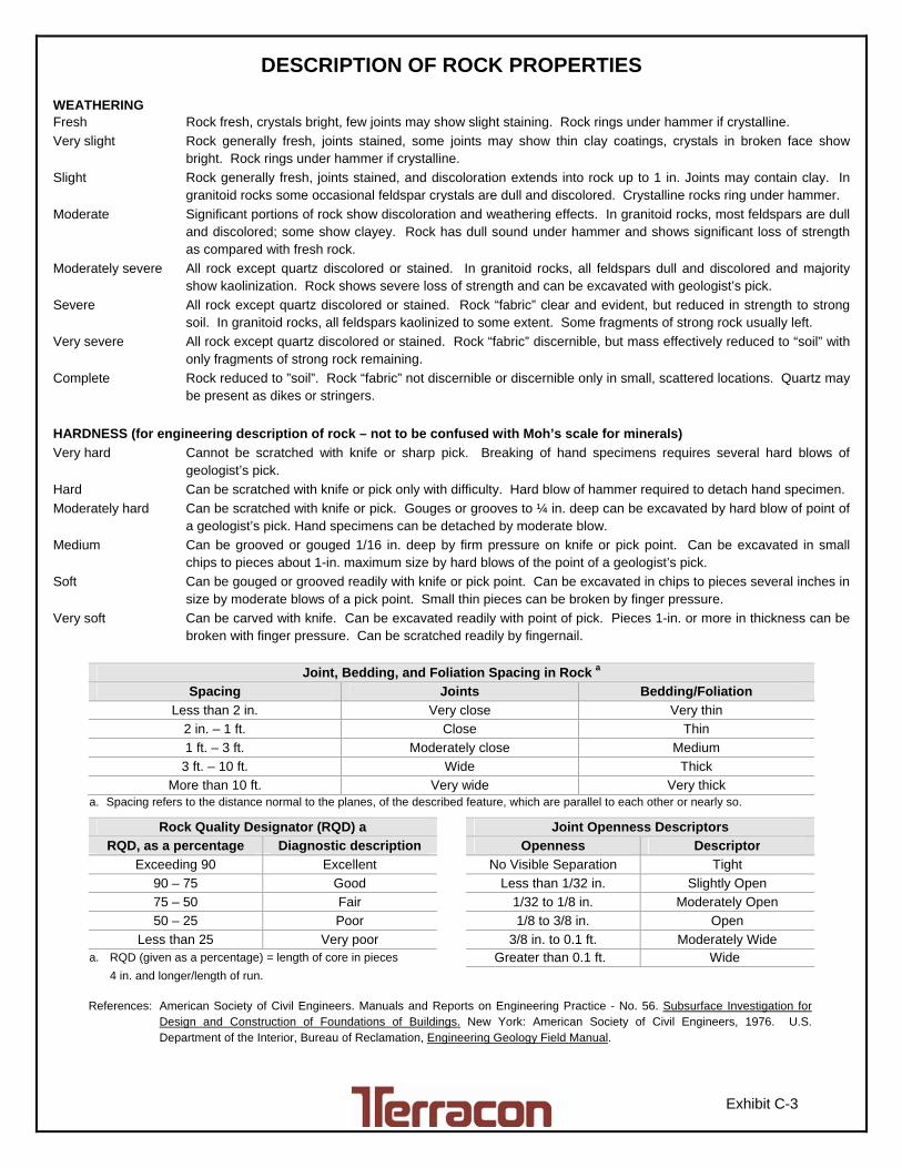
DESCRIPTION OF ROCK PROPERTIES
Exhibit C-3
WEATHERING Fresh Rock fresh, crystals bright, few joints may show slight staining. Rock rings under hammer if crystalline.
Very slight Rock generally fresh, joints stained, some joints may show thin clay coatings, crystals in broken face show bright. Rock rings under hammer if crystalline.
Slight Rock generally fresh, joints stained, and discoloration extends into rock up to 1 in. Joints may contain clay. In granitoid rocks some occasional feldspar crystals are dull and discolored. Crystalline rocks ring under hammer.
Moderate Significant portions of rock show discoloration and weathering effects. In granitoid rocks, most feldspars are dull and discolored; some show clayey. Rock has dull sound under hammer and shows significant loss of strength as compared with fresh rock.
Moderately severe All rock except quartz discolored or stained. In granitoid rocks, all feldspars dull and discolored and majority show kaolinization. Rock shows severe loss of strength and can be excavated with geologist’s pick.
Severe All rock except quartz discolored or stained. Rock “fabric” clear and evident, but reduced in strength to strong soil. In granitoid rocks, all feldspars kaolinized to some extent. Some fragments of strong rock usually left.
Very severe All rock except quartz discolored or stained. Rock “fabric” discernible, but mass effectively reduced to “soil” with only fragments of strong rock remaining.
Complete Rock reduced to ”soil”. Rock “fabric” not discernible or discernible only in small, scattered locations. Quartz may be present as dikes or stringers.
HARDNESS (for engineering description of rock – not to be confused with Moh’s scale for minerals)
Very hard Cannot be scratched with knife or sharp pick. Breaking of hand specimens requires several hard blows of geologist’s pick.
Hard Can be scratched with knife or pick only with difficulty. Hard blow of hammer required to detach hand specimen.
Moderately hard Can be scratched with knife or pick. Gouges or grooves to ¼ in. deep can be excavated by hard blow of point of a geologist’s pick. Hand specimens can be detached by moderate blow.
Medium Can be grooved or gouged 1/16 in. deep by firm pressure on knife or pick point. Can be excavated in small chips to pieces about 1-in. maximum size by hard blows of the point of a geologist’s pick.
Soft Can be gouged or grooved readily with knife or pick point. Can be excavated in chips to pieces several inches in size by moderate blows of a pick point. Small thin pieces can be broken by finger pressure.
Very soft Can be carved with knife. Can be excavated readily with point of pick. Pieces 1-in. or more in thickness can be broken with finger pressure. Can be scratched readily by fingernail.
Joint, Bedding, and Foliation Spacing in Rock a
Spacing Joints Bedding/Foliation
Less than 2 in. Very close Very thin
2 in. – 1 ft. Close Thin
1 ft. – 3 ft. Moderately close Medium
3 ft. – 10 ft. Wide Thick
More than 10 ft. Very wide Very thick a. Spacing refers to the distance normal to the planes, of the described feature, which are parallel to each other or nearly so.
Rock Quality Designator (RQD) a Joint Openness Descriptors
RQD, as a percentage Diagnostic description Openness Descriptor
Exceeding 90 Excellent No Visible Separation Tight
90 – 75 Good Less than 1/32 in. Slightly Open
75 – 50 Fair 1/32 to 1/8 in. Moderately Open
50 – 25 Poor 1/8 to 3/8 in. Open
Less than 25 Very poor 3/8 in. to 0.1 ft. Moderately Wide a. RQD (given as a percentage) = length of core in pieces Greater than 0.1 ft. Wide
4 in. and longer/length of run. References: American Society of Civil Engineers. Manuals and Reports on Engineering Practice - No. 56. Subsurface Investigation for
Design and Construction of Foundations of Buildings. New York: American Society of Civil Engineers, 1976. U.S. Department of the Interior, Bureau of Reclamation, Engineering Geology Field Manual.
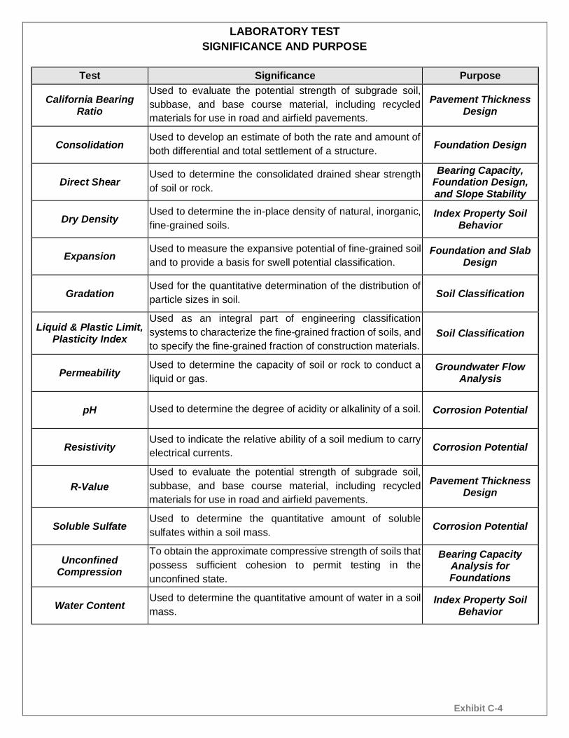
Exhibit C-4
LABORATORY TESTSIGNIFICANCE AND PURPOSE
Test Significance Purpose
California BearingRatio
Used to evaluate the potential strength of subgrade soil,subbase, and base course material, including recycledmaterials for use in road and airfield pavements.
Pavement ThicknessDesign
ConsolidationUsed to develop an estimate of both the rate and amount ofboth differential and total settlement of a structure. Foundation Design
Direct ShearUsed to determine the consolidated drained shear strengthof soil or rock.
Bearing Capacity,Foundation Design,and Slope Stability
Dry DensityUsed to determine the in-place density of natural, inorganic,fine-grained soils.
Index Property SoilBehavior
ExpansionUsed to measure the expansive potential of fine-grained soiland to provide a basis for swell potential classification.
Foundation and SlabDesign
GradationUsed for the quantitative determination of the distribution ofparticle sizes in soil. Soil Classification
Liquid & Plastic Limit,Plasticity Index
Used as an integral part of engineering classificationsystems to characterize the fine-grained fraction of soils, andto specify the fine-grained fraction of construction materials.
Soil Classification
PermeabilityUsed to determine the capacity of soil or rock to conduct aliquid or gas.
Groundwater FlowAnalysis
pH Used to determine the degree of acidity or alkalinity of a soil. Corrosion Potential
ResistivityUsed to indicate the relative ability of a soil medium to carryelectrical currents. Corrosion Potential
R-ValueUsed to evaluate the potential strength of subgrade soil,subbase, and base course material, including recycledmaterials for use in road and airfield pavements.
Pavement ThicknessDesign
Soluble SulfateUsed to determine the quantitative amount of solublesulfates within a soil mass. Corrosion Potential
UnconfinedCompression
To obtain the approximate compressive strength of soils thatpossess sufficient cohesion to permit testing in theunconfined state.
Bearing CapacityAnalysis forFoundations
Water ContentUsed to determine the quantitative amount of water in a soilmass.
Index Property SoilBehavior
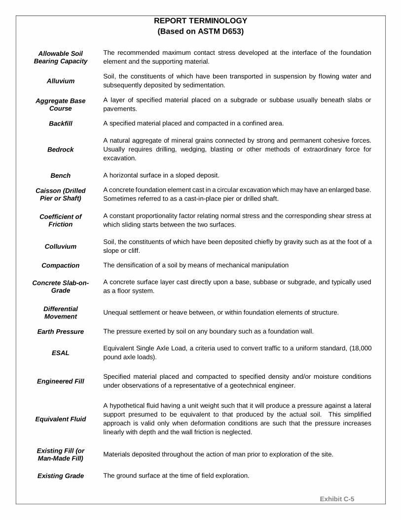
Exhibit C-5
REPORT TERMINOLOGY(Based on ASTM D653)
Allowable SoilBearing Capacity
The recommended maximum contact stress developed at the interface of the foundationelement and the supporting material.
AlluviumSoil, the constituents of which have been transported in suspension by flowing water andsubsequently deposited by sedimentation.
Aggregate BaseCourse
A layer of specified material placed on a subgrade or subbase usually beneath slabs orpavements.
Backfill A specified material placed and compacted in a confined area.
BedrockA natural aggregate of mineral grains connected by strong and permanent cohesive forces.Usually requires drilling, wedging, blasting or other methods of extraordinary force forexcavation.
Bench A horizontal surface in a sloped deposit.
Caisson (DrilledPier or Shaft)
A concrete foundation element cast in a circular excavation which may have an enlarged base.Sometimes referred to as a cast-in-place pier or drilled shaft.
Coefficient ofFriction
A constant proportionality factor relating normal stress and the corresponding shear stress atwhich sliding starts between the two surfaces.
ColluviumSoil, the constituents of which have been deposited chiefly by gravity such as at the foot of aslope or cliff.
Compaction The densification of a soil by means of mechanical manipulation
Concrete Slab-on-Grade
A concrete surface layer cast directly upon a base, subbase or subgrade, and typically usedas a floor system.
DifferentialMovement Unequal settlement or heave between, or within foundation elements of structure.
Earth Pressure The pressure exerted by soil on any boundary such as a foundation wall.
ESALEquivalent Single Axle Load, a criteria used to convert traffic to a uniform standard, (18,000pound axle loads).
Engineered FillSpecified material placed and compacted to specified density and/or moisture conditionsunder observations of a representative of a geotechnical engineer.
Equivalent Fluid
A hypothetical fluid having a unit weight such that it will produce a pressure against a lateralsupport presumed to be equivalent to that produced by the actual soil. This simplifiedapproach is valid only when deformation conditions are such that the pressure increaseslinearly with depth and the wall friction is neglected.
Existing Fill (orMan-Made Fill) Materials deposited throughout the action of man prior to exploration of the site.
Existing Grade The ground surface at the time of field exploration.
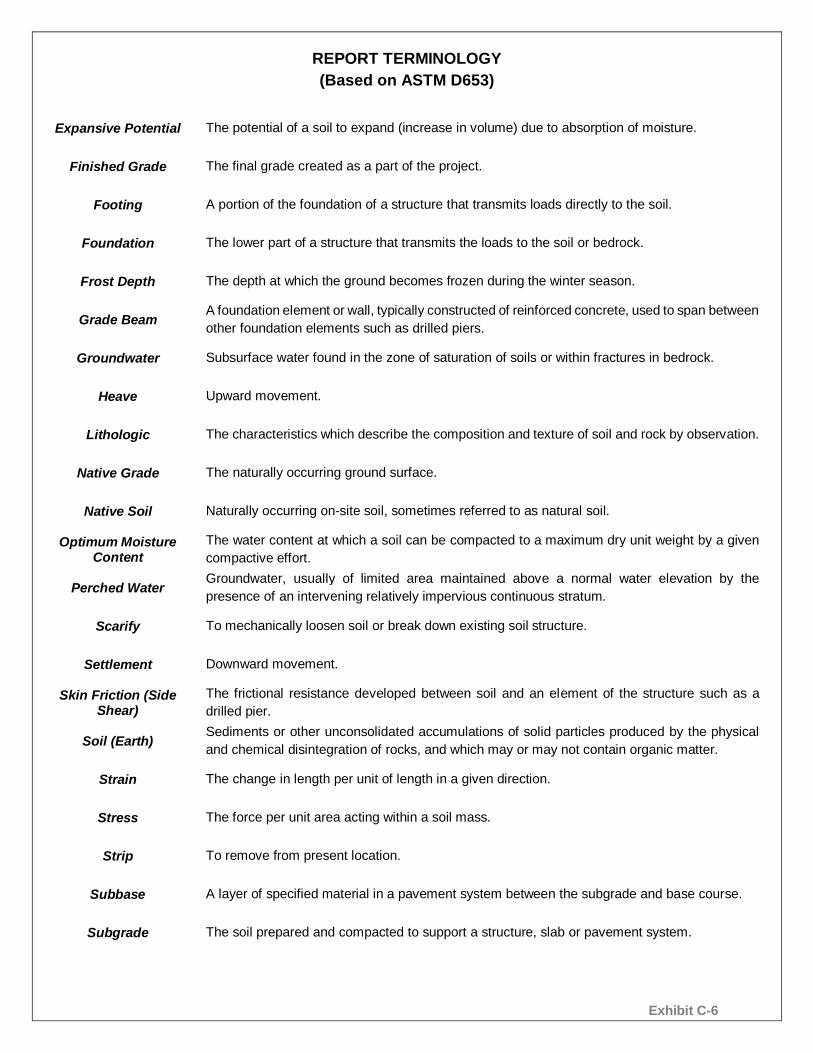
Exhibit C-6
REPORT TERMINOLOGY(Based on ASTM D653)
Expansive Potential The potential of a soil to expand (increase in volume) due to absorption of moisture.
Finished Grade The final grade created as a part of the project.
Footing A portion of the foundation of a structure that transmits loads directly to the soil.
Foundation The lower part of a structure that transmits the loads to the soil or bedrock.
Frost Depth The depth at which the ground becomes frozen during the winter season.
Grade BeamA foundation element or wall, typically constructed of reinforced concrete, used to span betweenother foundation elements such as drilled piers.
Groundwater Subsurface water found in the zone of saturation of soils or within fractures in bedrock.
Heave Upward movement.
Lithologic The characteristics which describe the composition and texture of soil and rock by observation.
Native Grade The naturally occurring ground surface.
Native Soil Naturally occurring on-site soil, sometimes referred to as natural soil.
Optimum MoistureContent
The water content at which a soil can be compacted to a maximum dry unit weight by a givencompactive effort.
Perched WaterGroundwater, usually of limited area maintained above a normal water elevation by thepresence of an intervening relatively impervious continuous stratum.
Scarify To mechanically loosen soil or break down existing soil structure.
Settlement Downward movement.
Skin Friction (SideShear)
The frictional resistance developed between soil and an element of the structure such as adrilled pier.
Soil (Earth)Sediments or other unconsolidated accumulations of solid particles produced by the physicaland chemical disintegration of rocks, and which may or may not contain organic matter.
Strain The change in length per unit of length in a given direction.
Stress The force per unit area acting within a soil mass.
Strip To remove from present location.
Subbase A layer of specified material in a pavement system between the subgrade and base course.
Subgrade The soil prepared and compacted to support a structure, slab or pavement system.