Embed Size (px)
Citation preview

Geotechnical Engineering Report Amara Apartments at the Rim
Talavera Ridge and Old Camp Bullis Road
San Antonio, Texas
June 27, 2016
Terracon Project No. 90165068
Prepared for:
Oden | Hughes
Austin, Texas
Prepared by:
Terracon Consultants, Inc.
San Antonio, Texas


Reliable ■ Resourceful ■ Responsive
TABLE OF CONTENTS
Page
EXECUTIVE SUMMARY ............................................................................................................. i
1.0 INTRODUCTION ............................................................................................................. 1
2.0 PROJECT INFORMATION ............................................................................................. 1
2.1 Project Description ........................................................................................... 1
2.2 Site Location and Description .......................................................................... 2
3.0 SUBSURFACE CONDITIONS ........................................................................................ 2
3.1 Site Geology ...................................................................................................... 2
3.2 Typical Profile ................................................................................................... 3
3.3 Groundwater ..................................................................................................... 3
4.0 RECOMMENDATIONS FOR DESIGN AND CONSTRUCTION ...................................... 4
4.1 Geotechnical Considerations ........................................................................... 4
4.1.1 General .................................................................................................... 4
4.1.2 Expansive Soil Considerations ................................................................. 4
4.1.3 Existing Fill Considerations ...................................................................... 5
4.1.4 Borrow Pit area......................................................................................... 5
4.2 Earthwork .......................................................................................................... 6
4.2.1 Site Preparation ........................................................................................ 6
4.2.2 Building Pad Preparation .......................................................................... 6
4.2.3 Material Requirements ............................................................................. 8
4.2.4 Compaction Requirements ....................................................................... 8
4.2.5 Grading and Drainage .............................................................................. 9
4.2.6 Earthwork Construction Considerations .................................................. 10
4.3 Foundations .................................................................................................... 10
4.3.1 Slab-on-Grade Foundation Design Recommendations ............................ 10
4.3.2 Shallow Foundation Construction Considerations ................................... 12
4.3.3 Drilled Piers Foundation ......................................................................... 12
4.3.4 Drilled Pier Construction Considerations ................................................ 14
4.3.5 Foundation Construction Monitoring ....................................................... 16
4.4 Seismic Considerations ................................................................................. 16
4.5 Swimming Pool ............................................................................................... 17
4.6 Pavements ....................................................................................................... 17
4.6.1 Subgrade Preparation ............................................................................ 18
4.6.2 Design Considerations ........................................................................... 18
4.6.3 Pavement Section Materials ................................................................... 20
4.6.4 Pavement Joints and Reinforcement ...................................................... 21
5.0 GENERAL COMMENTS ............................................................................................... 23

Reliable ■ Resourceful ■ Responsive
TABLE OF CONTENTS, CONTINUED
TABLE – LATERAL DESIGN PARAMETERS
APPENDIX A – FIELD EXPLORATION
Exhibit A-1 Site Location Map
Exhibit A-2 Boring and Test Pits Location Plan
Exhibit A-3 Field Exploration Description
Exhibit A-4 to A-23 Boring Logs
Exhibit A-24 to A-26 Test Pits Logs (reference Terracon Project No. 90155270)
APPENDIX B – LABORATORY TESTING
Exhibit B-1 Laboratory Testing
APPENDIX C – SUPPORTING DOCUMENTS
Exhibit C-1 General Notes
Exhibit C-2 Unified Soil Classification System

Geotechnical Engineering Report
Amara Apartments at the Rim ■ San Antonio, Texas
June 27, 2016 ■ Terracon Project No. 90165068
Reliable ■ Resourceful ■ Responsive i
EXECUTIVE SUMMARY
A geotechnical investigation has been performed for the proposed Amara Apartments at the Rim to
be constructed off of Talavera Ridge and Old Camp Bullis Road in San Antonio, Texas. Our
geotechnical engineering scope of work for this project included the advancement of 20 borings
at the project site to depths ranging from about 15 to 25 feet below the existing site grades.
Pertinent findings and recommendations generated from this study include those summarized
below:
The subsurface conditions at the boring locations are highly variable and consist of variable
fill materials with boulders and native Fat Clay, Lean Clay, Clayey Gravel underlain by highly
weathered Limestone.
Groundwater was not encountered in the borings during field activities.
The results of our laboratory tests indicate that the clayey soils encountered at the site are
low to highly plastic and will shrink and swell with changes in moisture content. The existing
Potential Vertical Rise (PVR) at the site is about 1 to 3 inches in its present condition and
depends on the encountered soil at each location. Detailed recommendations for building
pad preparation are included in the report. The recommendation should be reviewed and
possibly revised once the grading and finished floor elevations are available.
The proposed structures may be supported on a slab-on-grade foundation system provided
the building pads are prepared as recommended in this report. We understand the client has
selected a design PVR of 1½ inches.
Both flexible and rigid pavements may be considered for this project.
The International Building Code, Table 1613.3.2 IBC seismic site classification for this site
is C.
This summary should be used in conjunction with the entire report for design purposes. It should
be recognized that details were not included or fully developed in this section, and the report must
be read in its entirety for a comprehensive understanding of the items contained herein. The
section titled GENERAL COMMENTS should be read for an understanding of the report
limitations.

Reliable ■ Resourceful ■ Responsive 1
GEOTECHNICAL ENGINEERING REPORT
AMARA APARTMENTS AT THE RIM
TALAVERA RIDGE AND OLD CAMP BULLIS ROAD
SAN ANTONIO, TEXAS
TERRACON PROJECT NO. 90165068 JUNE 27, 2016
1.0 INTRODUCTION
Terracon Consultants, Inc. (Terracon) is pleased to submit our Geotechnical Engineering Report
for the proposed Amara Apartments at the Rim off of Talavera Ridge and Old Camp Bullis Road
in San Antonio, Texas. The project was authorized by Mr. Tim Shaughnessy on April 7, 2016
through signature of Terracon Proposal No. P90165068R2 dated April 7, 2016. This project was
completed in general accordance with the referenced proposal. The project was delayed due to
significant rainfall and access difficulties.
The purposes of this report are to describe the subsurface conditions observed at the borings
drilled for this study, analyze and evaluate the test data, and provide recommendations with
respect to:
subsurface soil conditions groundwater conditions
earthwork
seismic considerations
foundation design and construction
floor slab design and construction
pavements swimming pool
Preliminary information and a reconnaissance study were previously conducted by drilling borings
and test pits, Terracon Project No. 90155270. The report was provided to the client via email
dated January 29, 2016. This report supersedes all preliminary recommendations.
2.0 PROJECT INFORMATION
2.1 Project Description
Item Description
Site layout See Appendix A, Exhibits A-1 and A-2: Site Location Plan and Boring
Location Plan, respectively.

Geotechnical Engineering Report
Amara Apartments at the Rim ■ San Antonio, Texas
June 27, 2016 ■ Terracon Project No. 90165068
Reliable ■ Resourceful ■ Responsive 2
Item Description
Structures
The project will include the construction of:
■ 8 four to five-story apartment buildings with club house and
swimming pool. Two of the buildings will be interconnected
with the club house.
■ Two parking decks.
Associated pavements consisting of parking lots and drive lanes
Building Construction
■ The buildings are anticipated to be wood-framed or steel
framed structure; supported on a shallow slab-on-grade
foundation system. We understand the design PVR is 1½
inches.
■ The proposed parking decks are anticipated to be supported
by either slab on grade or drilled piers foundation system.
Maximum loads Column loads were not available at the time of this report. We
anticipate that loads will be light for this type of construction.
Grading Grading plans were not provided at the time of this report.
Finished floor elevation At or near existing grades within ±2 feet (assumed).
Pavements New parking and drive lanes. Both asphalt and concrete pavements
will be considered.
Traffic loads
No specific traffic volumes have been provided. Therefore, Terracon
anticipates that traffic loads will be produced primarily by automobile
traffic and occasional trash removal trucks.
2.2 Site Location and Description
Item Description
Location This project site is located off of Talavera Ridge and Old Camp Bullis
Road in San Antonio, Texas.
Existing improvements Undeveloped land.
Current ground cover Grass, weeds, stock piles, rocks boulders and fill materials in the
upper 5 feet.
3.0 SUBSURFACE CONDITIONS
3.1 Site Geology
The San Antonio Sheet (1983) of the Geologic Atlas of Texas published by the Bureau of
Economic Geology of the University of Texas at Austin has mapped the Glen Rose Formation
(Kgru and Kgrl) of Lower Cretaceous Geologic Age at this site. The Glen Rose Formation is

Geotechnical Engineering Report
Amara Apartments at the Rim ■ San Antonio, Texas
June 27, 2016 ■ Terracon Project No. 90165068
Reliable ■ Resourceful ■ Responsive 3
further divided into the Upper Member, with the geologic symbol Kgru, and the Lower Member,
with the geologic symbol Kgrl. The Glen Rose Formation consists of limestone, dolomite, and
marl as alternating resistant and recessive beds which forms a “stairstep” topography. The
limestone is aphanitic (individual grains are too fine to see with the naked eye) to fine grained,
hard to soft and marly. The dolomite is fine-grained and porous.
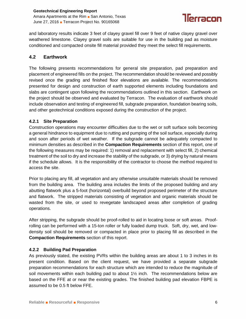
3.2 Typical Profile
Site soils consist of uncontrolled fill and natural soil over weathered Limestone. The fill material
is highly variable, including fat clay, lean clay and clayey gravel. The native soil is also variable
and consists of similar materials. Limestone was generally encountered below about 6 to 16 feet
in most of the borings.
The following table presents general information on the nature of the various soil types
encountered at this site.
Material Encountered Consistency/Density
The FAT CLAY (CH); dark brown and brown, gravelly and with sand. These
materials could undergo high to very high volumetric changes (shrink/swell)
should they experience changes in their in-place moisture content.
Soft to Hard
The LEAN CLAY, SANDY LEAN CLAY (CL); dark brown, brown, and reddish
brown, gravelly, sand. These materials could undergo low to moderate
volumetric changes (shrink/swell) should they experience changes in their in-
place moisture content.
Medium Stiff to Hard
The CLAYEY GRAVEL (GC); dark brown, brown and reddish brown, with clay
seams. This material is primarily granular in nature and could undergo low
volumetric changes (shrink/swell) should it experience changes in its in-place
moisture content. This stratum could be water bearing.
Medium Dense to Very
Dense
The WEATHERED LIMESTONE; tan, materials are expected to be
volumetrically stable Hard
Conditions encountered at each boring location are indicated on the individual boring logs.
Stratification boundaries on the boring logs represent the approximate location of changes in soil
types; in situ, the transition between materials may be gradual. Details for each of the borings
can be found on the boring logs in Appendix A of this report.
3.3 Groundwater
Groundwater generally appears as either a permanent or temporary water source. Permanent
groundwater is generally present year round, which may or may not be influenced by seasonal
and climatic changes. Temporary groundwater water is also referred to as a “perched” water
source, which generally develops as a result of seasonal and climatic conditions.

Geotechnical Engineering Report
Amara Apartments at the Rim ■ San Antonio, Texas
June 27, 2016 ■ Terracon Project No. 90165068
Reliable ■ Resourceful ■ Responsive 4
The borings were dry-augered to their full depths in an attempt to observe for the presence of
subsurface water. Subsurface water was not observed in the borings. Groundwater levels are
influenced by seasonal and climatic conditions which generally result in fluctuations in the
elevation of the groundwater level over time. The clayey gravel can easily transmit water.
Therefore, the foundation contractor should check the groundwater conditions just before
foundation excavation activities. The borings were backfilled with soil cuttings after the drilling
operations and groundwater observations were completed.
4.0 RECOMMENDATIONS FOR DESIGN AND CONSTRUCTION
4.1 Geotechnical Considerations
4.1.1 General
We anticipate that the proposed apartment buildings will be supported by shallow foundation
systems and pier foundations will be used for the proposed parking decks. The desired foundation
system may be used at this site provided the building pads and foundations are designed and
constructed as recommended in this report. Terracon would be pleased to discuss other
foundation alternatives with you upon request.
The foundations being considered must satisfy two independent engineering criteria with respect
to the subsurface conditions encountered at this site. One criterion is the foundation system must
be designed with an appropriate factor of safety to reduce the possibility of a bearing capacity
failure of the soils underlying the foundation when subjected to axial and lateral load conditions.
The other criterion is movement of the foundation system due to compression (consolidation or
shrinkage) or expansion (swell) of the underlying soils must be within tolerable limits for the
structures.
Based on our findings, the subsurface soil/fill at this site exhibits a variable expansion potential.
Based on the information developed from our field and laboratory programs and on method TEX-
124-E in the Texas Department of Transportation (TxDOT) Manual of Testing Procedures, we
estimate that the subgrade soils in the building area exhibit a Potential Vertical Rise (PVR) of
about 1 to 3 inches in its present condition. The actual movements could be greater than the
values presented in this report if inadequate drainage, ponded water, and/or other sources of
moisture are allowed to infiltrate beneath the structure after construction.
4.1.2 Expansive Soil Considerations
Low to highly expansive soils are present on this site. This report provides recommendations to
help mitigate the effects of soil shrinkage and expansion. However, even if these procedures are
followed, some movement and cracking in the structure should be anticipated. The severity of
cracking and other damage such as uneven floor slabs will probably increase if any modification
of the site results in excessive wetting or drying of the expansive soils.

Geotechnical Engineering Report
Amara Apartments at the Rim ■ San Antonio, Texas
June 27, 2016 ■ Terracon Project No. 90165068
Reliable ■ Resourceful ■ Responsive 5
Site grades should provide effective drainage away from the structures during and after
construction. Water permitted to pond next to these structures can result in greater soil
movements than those discussed in this report. These greater movements can result in
unacceptable differential floor slab movements, cracked slabs and walls, and roof leaks.
Estimated movements described in this report are based on effective drainage for the life of the
structures and cannot be relied upon if effective drainage is not maintained. Recommendations
for preparing the building pad to reduce soil movements are provided in the Building Pad
Preparation section of this report. Proper water management is important. Recommendations
regarding this issue are included in the Grading and Drainage section of this report.
4.1.3 Existing Fill Considerations
Onsite Fill Material – FILL thickness ranging between 2 to 7 feet was encountered in the borings
and test pits. The fill material consists of Lean Clay / Fat Clay with Gravel (CL-CH) and Clayey
Gravel (GC). Records for the fill placement were not available for our review. The Standard
Penetration Test (SPT) results and the blow count N-values indicate that the fill was placed under
some compaction effort, but not necessarily with controlled moisture and density. The borings
and test pits performed at the site cannot solely be relied on to evaluate the potential variability of
the FILL. It is possible that different conditions could exist between the boring locations than
those encountered at each bore location. Test Pits were performed at the site which revealed
some debris (boulders, concrete rubble, trash, rebars and metal pipes) in the fill. The contractor
should be aware of such situations. This risk of unforeseen conditions cannot be eliminated
without completely removing the existing fill, but can be reduced by preparing the subgrade as
recommended in this report.
Existing Stock Piles – Test pits were conducted to collect samples from the existing stock piles at
the site. Based on the laboratory results, the stockpiles soil material has plasticity indices ranged
between 30 and 38. Since the materials have high plasticity index, they are not suitable and
should not be considered for use as select fill.
Reuse of Existing Fill Materials – The debris (concrete, boulders, trash, rebars, etc.) varied
between depths of about 2 and 7 feet. Based on our review of the materials, the fill should be
excavated and sorted to remove the debris (boulders, concrete, rebars etc.). As discussed later
a portion of the excavated soil may be reused provided it is free of debris and properly processed.
The excavated soil after removal of debris should be blended to achieve a relatively uniform mix.
The maximum particle size of the prepared material should be 3 inches, or less. The blended soil
can be used to raise grades in pavements and other areas where there are no structures. If used,
the fill should then be placed in compacted lifts of about 6 inches. Each lift should be moisture
conditioned between 0 and +4 percentage points of optimum moisture content and compacted to
98 percent of ASTM D698.
4.1.4 Borrow Pit Area
Based on the provided information, the general area of boring B-19 is proposed to be mined as a
borrow pit area to be used as a select fill for the building pad areas. The boring log designation
Geotechnical Engineering Report
Amara Apartments at the Rim ■ San Antonio, Texas
June 27, 2016 ■ Terracon Project No. 90165068
Reliable ■ Resourceful ■ Responsive 6
and laboratory results indicate 3 feet of clayey gravel fill over 9 feet of native clayey gravel over
weathered limestone. Clayey gravel soils are suitable for use in the building pad as moisture
conditioned and compacted onsite fill material provided they meet the select fill requirements.
4.2 Earthwork
The following presents recommendations for general site preparation, pad preparation and
placement of engineered fills on the project. The recommendation should be reviewed and possibly
revised once the grading and finished floor elevations are available. The recommendations
presented for design and construction of earth supported elements including foundations and
slabs are contingent upon following the recommendations outlined in this section. Earthwork on
the project should be observed and evaluated by Terracon. The evaluation of earthwork should
include observation and testing of engineered fill, subgrade preparation, foundation bearing soils,
and other geotechnical conditions exposed during the construction of the project.
4.2.1 Site Preparation
Construction operations may encounter difficulties due to the wet or soft surface soils becoming
a general hindrance to equipment due to rutting and pumping of the soil surface, especially during
and soon after periods of wet weather. If the subgrade cannot be adequately compacted to
minimum densities as described in the Compaction Requirements section of this report, one of
the following measures may be required: 1) removal and replacement with select fill, 2) chemical
treatment of the soil to dry and increase the stability of the subgrade, or 3) drying by natural means
if the schedule allows. It is the responsibility of the contractor to choose the method required to
access the site.
Prior to placing any fill, all vegetation and any otherwise unsuitable materials should be removed
from the building area. The building area includes the limits of the proposed building and any
abutting flatwork plus a 5-foot (horizontal) overbuild beyond proposed perimeter of the structure
and flatwork. The stripped materials consisting of vegetation and organic materials should be
wasted from the site, or used to revegetate landscaped areas after completion of grading
operations.
After stripping, the subgrade should be proof-rolled to aid in locating loose or soft areas. Proof-
rolling can be performed with a 15-ton roller or fully loaded dump truck. Soft, dry, wet, and low-
density soil should be removed or compacted in place prior to placing fill as described in the
Compaction Requirements section of this report.
4.2.2 Building Pad Preparation
As previously stated, the existing PVRs within the building areas are about 1 to 3 inches in its
present condition. Based on the client request, we have provided a separate subgrade
preparation recommendations for each structure which are intended to reduce the magnitude of
soil movements within each building pad to about 1½ inch. The recommendations below are
based on the FFE at or near the existing grades. The finished building pad elevation FBPE is
assumed to be 0.5 ft below FFE.

Geotechnical Engineering Report
Amara Apartments at the Rim ■ San Antonio, Texas
June 27, 2016 ■ Terracon Project No. 90165068
Reliable ■ Resourceful ■ Responsive 7
Based on the PVR calculation for the existing condition of the on-site soil, the
buildings/structures are divided into three groups based on the amount of removal
and replace with select fill as following;
- Group A (Building 1, 2, 4, Club House, PD-1 and PD-2)
- Group B (Building 3, 5, 7 and 8)
- Group C (Building 6)
Complete stripping operations as discussed in the Site Preparation section.
Excavate and remove completely the existing fill material from each building area
and expose the native soil. The building area is defined as the area extending at
least 5 feet beyond the perimeter of the structure, including any flatwork that abuts
the structure such as sidewalks.
The exposed subgrade in the building areas should be proofrolled with at least a
15-ton roller, or equivalent equipment, to evidence any weak yielding zones. Over-
excavate any confirmed weak yielding zones, both vertically and horizontally, to
expose competent soil. The excavated soil can be used to restore grade provided
that the material is relatively free and clean of deleterious material or materials
exceeding 3 inches in maximum dimension. A Terracon geotechnical engineer or
their representative should be present to observe proofrolling operations.
After proofrolling and the replacement of weak yielding zones, scarify, moisture
condition, and compact the upper 6 inches of the newly exposed subgrade as
described in the Compaction Requirements section.
Place select fill material and on-site moisture conditioned soil to achieve the FBPE
of each building. Moisture condition and compact the select fill as described in the
Compaction Requirements section. Recommendations for select fill are included
in the Material Requirements section. Recommendations for moisture conditioning
and compaction of select fill materials are presented in the Compaction
Requirements section. On-site soil that meets the select fill requirements may be
used.
This will result in variable thicknesses of select fill over moisture conditioned and
compacted on-site soil beneath the various building pads as presented in following
table:
Group Existing PVR (inch) To Achieve 1½ inch PVR1
A 2 to 3 1½’ select Fill
B 1 to 1½ 1½’ select Fill
C 2½ 3’ Select Fill
1 The amount of removal and replacement presented for each group is based on removing
the entire fill material zone from the building/structure pad area.

Geotechnical Engineering Report
Amara Apartments at the Rim ■ San Antonio, Texas
June 27, 2016 ■ Terracon Project No. 90165068
Reliable ■ Resourceful ■ Responsive 8
To provide a more uniform slab support and create a more all-weather working
surface, consideration should be given to constructing the final 6 inches of the pad
with granular select fill. Recommendations for granular select fill are included in the
Material Requirements section of this report.
4.2.3 Material Requirements
Subsequent to proofrolling, and just prior to placement of all structural fill, the exposed subgrade
within the construction area should be evaluated for moisture and density. If the moisture, density,
and/or the requirements do not meet the criteria described in the table below, the subgrade should
be scarified to a depth of 6 inches; moisture adjusted and compacted to at least 95 percent of the
Standard Effort (ASTM D 698) maximum dry density. Select fill and on-site soils should meet the
following criteria.
Fill Type 1 USCS Classification Acceptable Location for Placement
Granular Select Fill 2 Varies Building pad (at least the upper 6 inches)
Onsite Soils meeting
the criteria for Select
Fill or Imported Select
Fill3
CL, GC, SC
(PI 7 to 20)
Suitable for onsite grade changes both inside and
outside of the building pad.
On-Site Soil CH, CL, GC
CH, soils are suitable for use in general grading and
pavement areas. These soils should not be used in
the building pad.
CL, GC, These onsite soils are suitable for use in the
building pad as moisture conditioned and compacted
onsite fill material provided they meet the select fill
requirements.
1 Prior to any filling operations, samples of the proposed borrow and on-site materials should be
obtained for laboratory moisture-density testing. The tests will provide a basis for evaluation of fill
compaction by in-place density testing. A qualified soil technician should perform sufficient in-place
density tests during the filling operations to evaluate that proper levels of compaction, including dry
unit weight and moisture content, are being attained. Controlled, compacted fill should consist of
approved materials that are free of organic matter and debris or materials exceeding 3 inches in
maximum dimension.
2 Granular select fill should consist of cohesive crushed limestone material with a maximum aggregate
size of 3 inches and PI between 5 and 12.
3 Select fill for the building pad should consist of a low plasticity lean clay, gravelly soils, or sandy soils
with a PI between 5 and 20 percent. This material is locally called “pit-run” material and may need to
be imported for this site. Some of the onsite soils may meet the criteria for select fill materials and should
be tested prior to use for this purpose.
4.2.4 Compaction Requirements
Item Description
Fill Lift Thickness All fill should be placed in thin, loose lifts of about 8 inches,
with compacted thickness not exceeding 6 inches.

Geotechnical Engineering Report
Amara Apartments at the Rim ■ San Antonio, Texas
June 27, 2016 ■ Terracon Project No. 90165068
Reliable ■ Resourceful ■ Responsive 9
Item Description
Compaction of Onsite Soil, or Select Fill;
(CH, CL, SC, GC) 95 percent of the material’s Standard Proctor maximum dry density (ASTM D 698).
Moisture Content of Onsite Granular Soil
or Select Fill; (CL, SC, GC) The materials should be moisture conditioned between -2 and +3 percentage points of the optimum moisture content.
Moisture Content of Onsite Clayey Soil The materials should be moisture conditioned between 0 and +4 percentage points of the optimum moisture content.
1 Unless otherwise noted within this report all compaction requirements are provided above.
4.2.5 Grading and Drainage
Effective drainage should be provided during construction and maintained throughout the life of
the development. After building construction and landscaping, we recommend verifying final
grades to document that effective drainage has been achieved. Grades around the structure
should also be periodically inspected and adjusted as necessary, as part of the structure’s
maintenance program.
Water permitted to pond next to the structure can result in distress in the structure including
unacceptable differential floor slab movements, cracked slabs and walls, and roof leaks. Building
slab and foundation performances described in this report are based on effective drainage for the
life of the structure and cannot be relied upon if effective drainage is not maintained.
Flatwork and pavements will be subject to post-construction movement. Maximum grades
practical should be used for paving and flatwork to prevent water from ponding. Allowances in
final grades should also consider post-construction movement of flatwork, particularly if such
movement would be critical. Where paving or flatwork abuts the structure, effectively seal and
maintain joints to prevent surface water infiltration. In areas where sidewalks or paving do not
immediately adjoin the structure, we recommend that protective slopes be provided with a grade
of at least three to five percent for at least 10 feet from perimeter walls (Except in areas where
ADA ramps are required; these should comply with state and local regulations). Backfill against
grade beams, exterior walls, and in utility and sprinkler line trenches should be well compacted
and free of construction debris to reduce the possibility of moisture infiltration.
Planters and other surface features which could retain water in areas adjacent to the structures
should be properly drained, designed, sealed or eliminated. Landscaped irrigation adjacent to the
foundation systems should be properly designed and controlled to help maintain a relatively
constant moisture content within 5 feet of the structure.
Collect roof runoff in drains or gutters. Discharge roof drains and downspouts onto pavements
and/or flatwork which slope away from the structure or extend downspouts a minimum of 5 feet
away from building.

Geotechnical Engineering Report
Amara Apartments at the Rim ■ San Antonio, Texas
June 27, 2016 ■ Terracon Project No. 90165068
Reliable ■ Resourceful ■ Responsive 10
4.2.6 Earthwork Construction Considerations
It is anticipated that excavations for the proposed construction can be accomplished with
conventional earthmoving equipment. Based upon the subsurface conditions determined from the
geotechnical exploration, subgrade soils exposed during construction are anticipated to be
relatively stable. However, the stability of the subgrade may be affected by precipitation, repetitive
construction traffic or other factors. If unstable conditions develop, workability may be improved
by scarifying and drying. Over excavation of wet zones and replacement with granular materials
may be necessary. Lightweight excavation equipment may be required to reduce subgrade
pumping. The use of remotely operated equipment, such as a backhoe, would be beneficial to
perform cuts and reduce subgrade disturbance.
All temporary excavations should be sloped or braced as required by Occupational Health and
Safety Administration (OSHA) regulations to provide stability and safe working conditions.
Temporary excavations will probably be required during grading operations. The grading
contractor, by his contract, is usually responsible for designing and constructing stable, temporary
excavations and should shore, slope or bench the sides of the excavations as required, to
maintain stability of both the excavation sides and bottom. All excavations should comply with
applicable local, state and federal safety regulations, including the current OSHA Excavation and
Trench Safety Standards.
4.3 Foundations
The building may be supported on a shallow slab-on-grade foundation system. Parking decks
may be supported by slab on-grade foundations or drilled pier foundation. Recommendations for
shallow foundation system are provided in the following sections.
4.3.1 Slab-on-Grade Foundation Design Recommendations
Based upon the subsurface conditions observed during our investigation, a shallow foundation
system would be appropriate to support the structural loads of the proposed buildings provided
the subgrade is prepared as discussed in the Building Pad Preparation section of this report.
Parameters commonly used to design this type of foundation are provided on the table below.
The slab foundation design parameters presented on the table below are based on the criteria
published by the Building Research Advisory Board (BRAB) and the Post-Tensioning Institute
(PTI) 3rd Edition. These are essentially empirical design methods and the recommended design
parameters are based on our understanding of the proposed project, our interpretation of the
information and data collected as a part of this study, our area experience, and the criteria
published in the BRAB and PTI design manuals.
Conventional Method Prepared Subgrade 1
Net Allowable Bearing Pressures 2 2,000 psf
Subgrade Modulus (k) 70 pci
Potential Vertical Rise (PVR) 1½ inch

Geotechnical Engineering Report
Amara Apartments at the Rim ■ San Antonio, Texas
June 27, 2016 ■ Terracon Project No. 90165068
Reliable ■ Resourceful ■ Responsive 11
BRAB Methods
Design Plasticity Index (PI) 3 34
Climatic Rating (Cw) 17
Unconfined Compressive Strength 1.0 tsf
Soil Support Index (C) 0.80
PTI Method 3rd Edition
Thornthwaite Moisture Index (Im) -14
Depth of Constant Soil Suction 9 feet
Constant Soil Suction 3.6 pF
Edge Moisture Variation Distance (em):
Center Lift 8.5 feet
Edge Lift 4.2 feet
Differential Soil Movement (ym):
Center Lift 1.5 inches
Edge Lift 1.1 inches
Coefficient of Slab-Subgrade Friction (): 0.75 to 1.00
1 Based on preparing the building pad as discussed in this report.
2 The net allowable bearing pressure provided above includes a Factor of Safety (FS) of at least 3.
We recommend that all grade beams be at least 24 inches below the Finished Building Pad
Elevation (FBPE) which corresponds to 30 inches below the FFE. These recommendations are
for proper development of bearing capacity for the continuous beam sections of the foundation
system and to reduce the potential for water to migrate beneath the slab foundation. These
recommendations are not based on structural considerations. Grade beam depths may need to
be greater than recommended herein for structural considerations and should be properly
evaluated and designed by the Structural Engineer.
For a slab foundation system designed and constructed as recommended in this report, post
construction settlements should be less than 1 inch. Settlement response of a select fill supported
slab is influenced more by the quality of construction than by soil-structure interaction. Therefore,
it is essential that the recommendations for foundation construction be strictly followed during the
construction phases of the building pad and foundation.
The use of a vapor retarder should be considered beneath concrete slabs-on-grade that will be
covered with wood, tile, carpet or other moisture sensitive or impervious coverings, or when the
slabs will support equipment sensitive to moisture. When conditions warrant the use of a vapor
retarder, the slab designer and slab contractor should refer to ACI 302 for procedures and
cautions about the use and placement of a vapor retarder.

Geotechnical Engineering Report
Amara Apartments at the Rim ■ San Antonio, Texas
June 27, 2016 ■ Terracon Project No. 90165068
Reliable ■ Resourceful ■ Responsive 12
4.3.2 Shallow Foundation Construction Considerations
The shallow foundations should preferably be neat excavated. Excavation should be
accomplished with a smooth-mouthed bucket. If a toothed bucket is used, excavation with this
bucket should be stopped 6 inches above the final bearing surface and the excavation completed
with a smooth-mouthed bucket or by hand labor. If neat excavation is not possible then the
foundation should be overexcavated and formed. All loose materials should be removed from the
overexcavated areas and filled with lean concrete or compacted cement stabilized sand (two
sacks cement to one cubic yard of sand) or flowable fill.
Steel should be placed and the foundation poured within 36 hours of excavation. If not, a seal
slab consisting of lean concrete should be poured to protect the exposed foundation soils. The
bearing surface should be excavated with a slight slope to create an internal sump for runoff water
collection and removal. If surface runoff water in excess of 1 inch accumulates at the bottom of
the excavation, it should be pumped out prior to concrete placement. Under no circumstances
should water be allowed to adversely affect the quality of the bearing surface.
Backfill soils above the foundation should consist of select fill. Backfill soils should be placed in
loose 8-inch lifts; moisture conditioned and compacted. Recommendations for select fill are
included in the Material Requirements section of this report.
4.3.3 Drilled Piers Foundation
The parking decks may be supported on drilled piers bearing at a depth no shallower than 15 feet
below existing grade or at least 5 feet into weathered limestone Stratum. Due to the presence of
clayey gravel and limestone, underreamed piers are not recommended.
Drilled piers may be designed for net allowable bearing pressure of 12,000 psf. This bearing
pressure include factor of safety against a bearing capacity failure of approximately 3. An
allowable side shear value of 400 psf, with an assumed factor of safety of at least 2, may be used
to aid in resisting axial compressive loads on the piers. The side shear should be neglected for
the upper 4 feet of soil in contact with the pier shaft. Piers should not extend deeper than 20 feet
below the existing grades at the time of our geotechnical field activities without contacting our
office. Piers should be designed with a shaft diameter at least 18 inches to facilitate inspection.
The allowable end bearing and skin friction values presented in this report are based on center-
to-center spacing of the pier foundations no closer than a horizontal distance of three shaft
diameters (using the larger bearing diameter). A closer spacing may be considered but may effect
(reduce) the axial capacity of the foundation depending on the spacing pattern of the foundations.
Terracon can assist in evaluating the possibility of a closer spacing once a foundation layout has
been determined.
In addition to the axial compressive loads on the piers, these piers will also be subjected to axial
tension loads due to the expansive soil conditions and possibly due to other induced structural
loading conditions. To compute the axial tension force due to the swelling soils along the pier
shaft, the following equation may be used.

Geotechnical Engineering Report
Amara Apartments at the Rim ■ San Antonio, Texas
June 27, 2016 ■ Terracon Project No. 90165068
Reliable ■ Resourceful ■ Responsive 13
Qu = 35·d
Where: Qu = Uplift force due to expansive soil conditions in kips (k)
d = Diameter of pier shaft in feet (ft)
This calculated force may be used to compute the longitudinal reinforcing steel required in the
pier to resist the uplift force induced by the swelling clays. However, the cross-sectional area of
the reinforcing steel should not be less than 1 percent of the gross cross-sectional area of the
drilled pier shaft. The reinforcing steel should extend from the top to the bottom of the shaft to
resist this potential uplift force.
The allowable uplift resistance of the straight sided drilled piers can be evaluated using the
following equation:
Qar = 3.0· d · Dp + 0.9 Wp + PDL
Where: Qar = Allowable uplift resistance of pier in kips (k)
d = Diameter of pier shaft in feet (ft)
Dp = Founding depth of pier in natural soils minus the upper 4
feet of shaft in contact with the soil in feet (ft)
Wp = Weight of the drilled pier in kips (k)
PDL = Dead Load acting on the drilled pier in kips (k)
The structural engineer may want to factor the dead load value based on their degree of certainty.
For adjacent piers, we recommend a minimum center-to-center spacing of at least 3 pier diameter
based on the larger diameter of the two adjacent piers. In locations where this minimum spacing
criterion cannot be accomplished, Terracon should be contacted to evaluate the locations on a
case-by-case basis.
Total settlements, based on the indicated bearing pressures, should be about 1 inch for properly
designed and constructed drilled piers. Settlement beneath individual piers will be primarily elastic
with most of the settlement occurring during construction. Differential settlement may also occur
between adjacent piers. The amount of differential settlement could approach 50 to 75 percent of
the total pier settlement. For properly designed and constructed piers, differential settlement
between adjacent piers is estimated to be less than ¾ of an inch. Settlement response of drilled
piers is impacted more by the quality of construction than by soil-structure interaction.
Improper pier installation could result in differential settlements significantly greater than we have
estimated. In addition, larger magnitudes of settlement should be expected if the soil is subjected
to bearing pressures higher than the allowable values presented in this report.

Geotechnical Engineering Report
Amara Apartments at the Rim ■ San Antonio, Texas
June 27, 2016 ■ Terracon Project No. 90165068
Reliable ■ Resourceful ■ Responsive 14
Lateral Loading - The piers supporting the light poles may be subjected to lateral loading. The
criteria for lateral load analysis is presented in Table 1 are for use with the computer program
LPILE. A number of methods, including hand solutions and computer programs, are available for
calculating the lateral behavior of piles and drilled piers. The majority of these methods rely on
“key” soil parameters such as soil elastic properties (E and ks), strain at 50 percent of the principal
stress difference (50), undrained shear strength (c), and load-deflection (p-y) criteria. The p-y
criteria, which are commonly used to model soil reaction, were developed from instrumented load
tests and are generally considered to provide the best model of soil behavior under short-term
lateral loading.
It should be noted that the initial elastic moduli for soil and rock are referred to as soil modulus (k)
and as initial rock modulus (Eri) on Table 1, and in the LPILE program. The Eri values refer to the
Young’s modulus, in pounds per square inch (psi), as described in the notes of the table. In the
same fashion, the equivalent strain factor for rock materials is referred to as krm.
Factors of safety are not generally applied to the lateral load analysis. A performance criteria, or
“limit state”, are usually considered. For most foundations subjected to lateral loads, the pier
foundation is designed with a limit of 1 inch of deflection at the top of the pier and 1 degree of
rotation as measured from the vertical axis of the pier. The analysis is generally conducted using
the working loads and the limit state values. The applied loads are then doubled to evaluate the
deflection and rotation at the top of the pier to determine if the foundation will topple over under
extreme overload. This overload condition may indicate that the foundation would deflect or rotate
such that the tower will tilt but the foundation will not experience failure. Structural limits, such as
moment capacity and shear, may control the design and should be evaluated by the Structural
Engineer.
4.3.4 Drilled Pier Construction Considerations
The pier excavations should be augered and constructed in a continuous manner. Steel and
concrete should be placed in the pier excavations immediately following drilling and evaluation
for proper bearing stratum, embedment, and cleanliness. Under no circumstances should the pier
excavations remain open overnight. Due to the presence of limestone; high torque, high
powered (rock) drilling equipment will be required.
During the time of our drilling operations, subsurface water was not encountered. Subsurface
water levels are influenced by seasonal and climatic conditions which result in fluctuations in
subsurface water elevations. Clayey Gravel were also encountered during drilling. Therefore
caving of the pier walls during excavation should be anticipated. Therefore, the contractor should
be prepared to use temporary casing should water be encountered and/or sloughing of the
excavation sidewalls occur. It is the responsibility of the foundation contractor to choose the
casing, type, depth and method of installation. The casing method is discussed in the following
paragraphs.

Geotechnical Engineering Report
Amara Apartments at the Rim ■ San Antonio, Texas
June 27, 2016 ■ Terracon Project No. 90165068
Reliable ■ Resourceful ■ Responsive 15
Casing Method- Casing should provide stability of the excavation walls and should
reduce water influx; however, casing may not completely eliminate subsurface water
influx potential. In order for the casing to be effective, a “water tight” seal must be
achieved between the casing and surrounding soils. The drilling subcontractor
should determine casing depths and casing procedures. Water that accumulates in
excess of 3 inches in the bottom of the pier excavation should be pumped out prior
to steel and concrete placement. If the water is not pumped out, a closed-end tremie
should be used to place the concrete completely to the bottom of the pier excavation
in a controlled manner to effectively displace the water during concrete placement.
If water is not a factor, concrete may be placed with a short tremie so the concrete
is directed to the bottom of the pier excavation. The concrete should not be allowed
to ricochet off the walls of the pier excavation nor off the reinforcing steel. If this
operation is not successful or to the satisfaction of the foundation contractor, the pier
excavation should be flooded with fresh water to offset the differential water pressure
caused by the unbalanced water levels inside and outside of the casing. The
concrete should be tremied completely to the bottom of the excavation with a closed-
end tremie.
Removal of casing should be performed with extreme care and under proper
supervision to reduce mixing of the surrounding soil and water with the fresh
concrete. Rapid withdrawal of casing or the auger may develop suction that could
cause the soil to intrude into the excavation. An insufficient head of concrete in the
casing during its withdrawal could also allow the soils to intrude into the wet concrete.
Both of these conditions may induce “necking”, a section of reduced diameter, in the
pier.
All aspects of concrete design and placement should comply with the American Concrete Institute
(ACI) 318 Code Building Code Requirements for Structural Concrete, ACI 336.1 Standard
Specification for the Construction of Drilled Piers, and ACI 336.3R entitled Suggested Design and
Construction Procedures for Pier Foundations. Concrete should be designed to achieve the
specified minimum 28-day compressive strength when placed at a 7 inch slump with a 1 inch
tolerance. Adding water to a mix designed for a lower slump does not meet the intent of this
recommendation. If a high range water reducer is used to achieve this slump, the span of slump
retention for the specific admixture under consideration should be thoroughly investigated.
Compatibility with other concrete admixtures should also be considered. A technical
representative of the admixture supplier should be consulted on these matters.
Successful installation of drilled piers is a coordinated effort involving the general contractor,
design consultants, subcontractors and suppliers. Each must be properly equipped and prepared
to provide their services in a timely fashion. Several key items are:
Proper drilling rig with proper equipment (including high torque, high powered rock
drilling equipment).

Geotechnical Engineering Report
Amara Apartments at the Rim ■ San Antonio, Texas
June 27, 2016 ■ Terracon Project No. 90165068
Reliable ■ Resourceful ■ Responsive 16
Reinforcing steel cages tied to meet project specifications;
Proper scheduling and ordering of concrete for the piers; and
Monitoring of installation by design professionals.
Pier construction should be carefully monitored to assure compliance of construction activities
with the appropriate specifications. A number of items recommended for monitoring during pier
installation include those listed below.
Pier locations Concrete properties and placement
Vertical alignment Casing removal (if required)
Competent bearing Proper casing seal for subsurface water control
Steel placement
If the contractor has to deviate from the recommended foundations, Terracon should be notified
immediately so additional engineering recommendations can be provided for an appropriate
foundation type.
4.3.5 Foundation Construction Monitoring
The performance of the foundation system for the proposed structure will be highly dependent
upon the quality of construction. Thus, we recommend that fill pad compaction and foundation
installation be monitored by an experienced Terracon soil technician under the direction of our
Geotechnical Engineer. We would be pleased to develop a plan for compaction and foundation
installation monitoring to be incorporated in the overall quality control program.
4.4 Seismic Considerations
Description Value
2012 International Building Code Site Classification (IBC) 1 C 2
Site Latitude (Degrees) 29.62234°N
Site Longitude (Degrees) 98.60414°W
Mapped Spectral Acceleration for Short Periods (0.2-Second): (SS) 3 0.072g
Mapped Spectral Acceleration for a 1-Second Period: (S1) 3 0.030g
1 The site class definition was determined using SPT N-values in conjunction with section 1613.3.2 in
the 2012 IBC and Table 20.3-1 in the 2010 ASCE-7.
2 Borings extended to a maximum depth of 25 feet, and this seismic site class definition considers that
Hard soil continues below the maximum depth of the subsurface exploration.
3 The Spectral Acceleration values were determined using publicly available information provided on
the United States Geological Survey (USGS) website. The spectral acceleration values can be used
to determine the site coefficients using Tables 1613.3.3 (1) and 1613.3.3 (2) in the 2012 IBC.

Geotechnical Engineering Report
Amara Apartments at the Rim ■ San Antonio, Texas
June 27, 2016 ■ Terracon Project No. 90165068
Reliable ■ Resourceful ■ Responsive 17
4.5 Swimming Pool
The proposed swimming pool walls will be subject to lateral earth pressures induced by the soil
retained by those walls, and should consider the drainage conditions behind the wall. Swimming
pool walls should be designed to resist “at rest” earth pressures due to their generally non-yielding
nature.
If the pool is constructed using a “gunite” technique, then the equivalent fluid density will be
dictated by the natural soil. With the gunite method, installation of drainage material is not
practical. Therefore, the design pressures should consider full hydrostatic conditions behind the
wall.
If the soils are mass excavated and the swimming pool is formed and placed, then the backfill can
consist of select materials such as clean, free-draining sand or gravel, which will allow the
equivalent fluid density exerted on the pool walls to be controlled to some extent. The select
granular fill should extend behind the heel of the wall and extend upward to the ground surface at
an angle of 45 degrees or flatter. If the pool walls are backfilled with select granular fill, then a
drainage system comprised of slotted or perforated PVC pipe encased by clean sand or gravel
that is completely wrapped in filter fabric should be considered for behind-wall construction to
further control the equivalent fluid density. However, if this drainage system fails to perform as
intended, then full hydrostatic pressures may occur.
The following equivalent fluid densities may be used for the design of the swimming pool walls at
this site depending upon whether or not reliable drainage is provided behind the wall. The
following equivalent fluid densities do not account for any surcharge loads.
Retained Material Type
Drainage Condition
Equivalent Fluid Density (pcf)
With Hydrostatic Forces Without Hydrostatic Forces
Clayey Gravel 95 65
Lean Clay Soil 100 80
Free-Draining Sand/Gravel 90 55
We recommend that the walls of the pool be designed assuming no pressure from the water in
the pool; i.e. an empty pool.
4.6 Pavements
Both flexible and rigid pavement systems may be considered for the project. Based on our
knowledge of the project, we anticipate that traffic loads will be produced primarily by automobile
traffic and occasional delivery and trash removal trucks.

Geotechnical Engineering Report
Amara Apartments at the Rim ■ San Antonio, Texas
June 27, 2016 ■ Terracon Project No. 90165068
Reliable ■ Resourceful ■ Responsive 18
4.6.1 Subgrade Preparation
Prior to placing any fill, vegetation and any otherwise unsuitable materials should be removed
from the new pavement areas. After stripping, the subgrade should be proof-rolled to aid in
locating loose or soft areas. Proof-rolling can be performed with a 15-ton roller or fully loaded
dump truck. Wet, soft, low-density or dry material should either be removed or moisture
conditioned and recompacted to the moisture contents and densities described in the
Compaction Requirements section prior to placing fill.
4.6.2 Design Considerations
For this project Light and Heavy pavement section alternatives have been provided. A light section
is for areas expected to receive only car traffic. A heavy section assumes areas with heavy traffic,
such as trash pickup areas and main access drive areas.
The flexible pavement section was designed in general accordance with the National Asphalt
Pavement Association (NAPA) Information Series (IS-109) method (Class 1 for Light and Class
2 for Heavy). The rigid pavement section was designed using the American Concrete Institute
(ACI 330R-01) method (Traffic Category A (ADTT=0) for Light and A-1 (ADTT=10) for Heavy). If
heavier traffic loading is expected, Terracon should be provided with the information and allowed to
review these pavement sections.
FLEXIBLE PAVEMENT SYSTEM (inches)
Raw Subgrade Modified Subgrade
Light
Duty
Heavy
Duty
Dumpster
Location
Light
Duty
Heavy
Duty
Dumpster
Location
Hot Mix Asphaltic Concrete 2.0 2.5 NR 2 2.0 2.5 NR 2
Base Material 1 10.0 14.0 NR 2 6.0 10.0 NR 2
Modified Subgrade3 ---- ---- NR 2 6.0 6.0 NR 2
Moisture Conditioned Subgrade 6.0 6.0 NR 2 ---- ---- NR 2
1 Asphaltic base material may be used in place of crushed limestone base material. Every 2.5 inches
of crushed limestone base material may be replaced with 1 inch of asphaltic base material. However,
the minimum thickness of the asphaltic base material is 4 inches.
2 NR = Not Recommended
3 As an alternative to a lime treated subgrade beneath the flexible pavements, a geogrid such as
Tensar BX-1100 or Tensar TX-140 may be used at the interface between the subgrade soils and the
base material.

Geotechnical Engineering Report
Amara Apartments at the Rim ■ San Antonio, Texas
June 27, 2016 ■ Terracon Project No. 90165068
Reliable ■ Resourceful ■ Responsive 19
RIGID PAVEMENT SYSTEM (inches)
Raw Subgrade Modified Subgrade
Light
Duty
Heavy
Duty
Dumpster
Location
Light
Duty
Heavy
Duty
Dumpster
Location
Reinforced Concrete 5.5 6.5 7.0 5.0 6.0 6.5
Modified Subgrade ---- ---- ---- 6.0 6.0 6.0
Moisture Conditioned Subgrade 6.0 6.0 6.0 ---- ---- ----
The pavement subgrade is expected to consist of natural undisturbed soils or fill material in cut
areas, and fill utilizing soils taken from the cut to raise grades where required. Proper perimeter
drainage is very important and should be provided so infiltration of surface water from unpaved
areas surrounding the pavement is minimized. We do not recommend installation of landscape
beds or islands in the pavement areas. Such features provide an avenue for water to enter into
the pavement section and underlying soil subgrade. Water penetration usually results in
degradation of the pavement section with time as vehicular traffic traverses the affected area.
Therefore, positive drainage should be established and maintained throughout the life of the
pavement.
Curbs should extend through the base and at least 3 inches into the soil subgrade below the base
course. This will help reduce migration of subsurface water into the pavement base course from
adjacent areas. A crack sealant compatible to both asphalt and concrete should be provided at
all concrete-asphalt interfaces.
Pavement areas that will be subjected to heavy wheel and traffic volumes, such as waste bin or
"dumpster" areas, entrance/exit ramps, and delivery areas, should be a rigid pavement section
constructed of reinforced concrete. The concrete pavement areas should be large enough to
properly accommodate the vehicular traffic and loads. For example:
The dumpster pad should be large enough so that the wheels of the collection
truck are entirely supported on the concrete pavement during lifting of the waste
bin; and
The concrete pavement should extend beyond any areas that require extensive
turning, stopping, and maneuvering.
The pavement design engineer should consider these and other similar situations when planning
and designing pavement areas. Waste bin and other areas that are not designed to accommodate
these situations often result in localized pavement failures.
The pavement section has been designed using generally recognized structural coefficients for
the pavement materials. These structural coefficients reflect the relative strength of the pavement
materials and their contribution to the structural integrity of the pavement. If the pavement does
not drain properly, it is likely that ponded water will infiltrate the pavement materials resulting in a

Geotechnical Engineering Report
Amara Apartments at the Rim ■ San Antonio, Texas
June 27, 2016 ■ Terracon Project No. 90165068
Reliable ■ Resourceful ■ Responsive 20
weakening of the materials. As a result, the structural coefficients of the pavement materials will
be reduced and the life and performance of the pavement will be shortened. The Asphalt Institute
recommends a minimum of 2 percent slope for asphalt pavements. The importance of proper
drainage cannot be overemphasized and should be thoroughly considered by the project team.
4.6.3 Pavement Section Materials
Hot Mix Asphaltic Concrete Surface Course - The asphaltic concrete surface
course should be plant mixed, hot laid Type C or D Surface. The asphaltic concrete
base course should also be plant mixed, hot laid Type A or B. Each mix should
meet the master specifications requirements of 2004 TXDOT Standard
Specifications Item 341, Item SS 3224 (2011) and specific criteria for the job mix
formula. The mix should be compacted between 91 and 95 percent of the
maximum theoretical density as measured by TEX-227-F. The asphalt cement
content by percent of total mixture weight should fall within a tolerance of ±0.3
percent asphalt cement from the specific mix. In addition, the mix should be
designed so 75 to 85 percent of the voids in the mineral aggregate (VMA) are filled
with asphalt cement. The grade of the asphalt cement should be PG 64-22 or
higher performance grade. Aggregates known to be prone to stripping should not
be used in the hot mix. If such aggregates are used measures should be taken to
mitigate this concern. The mix should have at least 70 percent strength retention
when tested in accordance with TEX-531-C.
Pavement specimens, which shall be either cores or sections of asphaltic
pavement, will be tested according to Test Method TEX-207-F. The nuclear-
density gauge or other methods which correlate satisfactorily with results obtained
from project pavement specimens may be used when approved by the Engineer.
Unless otherwise shown on the plans, the Contractor shall be responsible for
obtaining the required pavement specimens at their expense and in a manner and
at locations selected by the Engineer.
Concrete - Concrete should have a minimum 28-day design compressive strength
of 4,000 psi.
Granular Base Material Base material may be composed of crushed limestone
base/ crushed concrete meeting all of the requirements of 2004 TxDOT Item 247,
Type A or D, Grade 1 or 2; including triaxial strength.
Asphaltic Base Course - The asphaltic base material should meet the
specification requirements of 2004 TxDOT Standard Specification Item 340, Type
A or B.

Geotechnical Engineering Report
Amara Apartments at the Rim ■ San Antonio, Texas
June 27, 2016 ■ Terracon Project No. 90165068
Reliable ■ Resourceful ■ Responsive 21
Modified Subgrade - Due to the presence of clay at this site, the subgrade may
be treated with hydrated lime in accordance with TxDOT Item 260 in order to
improve its strength and improve its load carrying capacity. If granular soils are
exposed in the subgrade, cement may be used. If a modified subgrade is chosen,
the subgrade soils should be tested for sulfates due to the possibility of a reaction
between the calcium-based modifiers and sulfates in the soil.
We anticipate that approximately 6 percent hydrated lime will be required. This is
equivalent to about 27 pounds of hydrated lime per square yard for a 6 inch
treatment depth. However, the actual percentage should be determined by
laboratory tests on samples of the clayey subgrade prior to construction. The
optimum lime content should result in a soil-lime mixture with a pH of at least 12.4
when tested in accordance with ASTM C 977, Appendix XI and should reduce the
Plasticity Index to 20 or less.
For lime-treated subgrade, the lime should initially be blended with a mixing device
such as a Pulvermixer, sufficient water added, and be allowed to cure for at least
48 hours. After curing, the lime-soil should be remixed to meet the in-place
gradation requirements of Item 260 and compacted to at least 95 percent of the
maximum dry density determined in accordance with ASTM D 698 at moisture
contents ranging from optimum and 4 percentage points above the optimum
moisture content.
Moisture Conditioned Subgrade - The subgrade should be scarified to a depth
of 6 inches and then moisture conditioned and compacted as recommended in the
Compaction Requirements section of this report.
Details regarding subgrade preparation, fill materials, placement and compaction are presented
in the Earthwork section under the Material Requirements and Compaction Requirements
subsections.
4.6.4 Pavement Joints and Reinforcement
The following is recommended for all concrete pavement sections in this report. Refer to ACI 330
“Guide for Design and Construction of Concrete Parking Lots” for additional information.
Contraction Joint Spacing: 12½ feet each way for pavement thickness of 5 or 5½
inches; 15 feet each way for pavement thickness of 6 or
greater.
Contraction Joint Depth: At least ¼ of pavement thickness.
Contraction Joint Width: One-fourth inch or as required by joint sealant
manufacturer.

Geotechnical Engineering Report
Amara Apartments at the Rim ■ San Antonio, Texas
June 27, 2016 ■ Terracon Project No. 90165068
Reliable ■ Resourceful ■ Responsive 22
Construction Joint Spacing: To attempt to limit the quantity of joints in the pavement,
consideration can be given to installing construction joints at
contraction joint locations, where it is applicable.
Construction Joint Depth/Width: Full depth of pavement thickness. Construct sealant
reservoir along one edge of the joint. Width of reservoir to
be ¼ inch or as required by joint sealant manufacturer.
Depth of reservoir to be at least ¼ of pavement thickness.
Isolation Joint Spacing: As required to isolate pavement from structures, etc.
Isolation Joint Depth: Full depth of pavement thickness.
Isolation Joint Width: One-half to 1 inch or as required by the joint sealant
manufacturer.
Expansion Joint: None (see note below)
Note: Long, linear pavements may require expansion joints. However, in this locale, drying
shrinkage of concrete typically significantly exceeds anticipated expansion due to
thermal affects. As a result, the need for expansion joints is eliminated provided all
joints (including saw cuts) are sealed. Construction of an unnecessary joint may be
also become a maintenance problem. All joints should be sealed. If all joints, including
sawcuts, are not sealed then expansion joints should be installed.
Distributed Steel: Steel reinforcement may consist of steel bars described as follows:
No 3 reinforcing steel bars at 18 inches on-center-each-way, Grade 60.
No 4 reinforcing steel bars at 24 inches on-center-each-way, Grade 60.
Note: It is imperative that the distributed steel be positioned accurately in the pavement cross
section, namely 2 inches from the top of the pavement.
All construction joints have dowels. Dowel information varies with pavement thickness as
presented as follows:
Pavement Thickness: 5, 5½ inches 6, 6½ inches 7 inches
Dowels: ⅝ inch diameter ¾ inch diameter ⅞ inch diameter
Dowel Spacing: 12 inches on center 12 inches on center 12 inches on center
Dowel Length: 12 inches long 14 inches long 14 inches long
Dowel Embedment: 5 inches 6 inches 6 inches

Geotechnical Engineering Report
Amara Apartments at the Rim ■ San Antonio, Texas
June 27, 2016 ■ Terracon Project No. 90165068
Reliable ■ Resourceful ■ Responsive 23
5.0 GENERAL COMMENTS
Terracon should be retained to review the final design plans and specifications so comments can
be made regarding interpretation and implementation of our geotechnical recommendations in the
design and specifications. Terracon also should be retained to provide observation and testing
services during grading, excavation, foundation construction and other earth-related construction
phases of the project.
The analysis and recommendations presented in this report are based upon the data obtained
from the borings performed at the indicated locations and from other information discussed in this
report. This report does not reflect variations that may occur between borings, across the site, or
due to the modifying effects of construction or weather. The nature and extent of such variations
may not become evident until during or after construction. If variations appear, we should be
immediately notified so that further evaluation and supplemental recommendations can be
provided. Prospective contractors should familiarize themselves with the conditions at the site and
retain their own experts to interpret the data in this report and perform additional testing and/or
inspection as they deem necessary prior to bidding.
The scope of services for this project does not include either specifically or by implication any
environmental or biological (e.g., mold, fungi, bacteria) assessment of the site or identification or
prevention of pollutants, hazardous materials or conditions. If the owner is concerned about the
potential for such contamination or pollution, other studies should be undertaken.
This report has been prepared for the exclusive use of our client for specific application to the
project discussed and has been prepared in accordance with generally accepted geotechnical
engineering practices. No warranties, either express or implied, are intended or made. Site
safety, excavation support, and dewatering requirements are the responsibility of others. In the
event that changes in the nature, design, or location of the project as outlined in this report are
planned, the conclusions and recommendations contained in this report shall not be considered
valid unless Terracon reviews the changes and either verifies or modifies the conclusions of this
report in writing.

TABLE

Geotechnical Engineering Report
Amara Apartments at the Rim ■ San Antonio, Texas
June 27, 2016 ■ Terracon Project No. 90165068
Reliable ■ Resourceful ■ Responsive Table 1
TABLE 1
LATERAL DESIGN PARAMETERS
AMARA APARTMENTS AT THE RIM
TALAVERA RIDGE AND OLD CAMP BULLIS ROAD
SAN ANTONIO, TEXAS
TERRACON PROJECT NO. 90165068
Layer
Depth to
Bottom
of Layer
(feet)
Total Unit
Weight
(pcf)
Effective
Unit Weight
(pcf)
Undrained
Shear Strength
(psf)
Soil Strain
Factor
(50)
LPILE Soil Types
Friction Angle
(degrees)
RQD (%)5
Subgrade
Modulus, k6
(pci)
1 4 120 120 1,000 0.010 Stiff Clay without Water --- --- 425
2 12 115 115 --- --- Sand 32 --- 129
3 25 130 130 100 psi4 0.0005 Weak Rock --- 20 70,000
1 Design depth to subsurface water is below 25 feet.
2 Stratigraphy shown above is based on our interpretation of soil strength and may not correspond with the descriptive classifications shown on the boring logs.
3 The lateral load criteria shown above are for use in the computer programs LPILE.
4 Uniaxial compressive strength of rock is in psi.
5 RQD value is assumed.
6 K-value given for Weak Rock is Eri in psi.

APPENDIX A

SITE LOCATION PLAN
Amara Apartments at the Rim Talavera Ridge and Old Camp Bullis Road
San Antonio, Texas
6911 Blanco Rd
San Antonio, TX 78216-6164
90165068
AERIAL PHOTOGRAPHY PROVIDED BYGOOGLE EARTH
Project Manager:
Drawn by:
Checked by: Approved by:
TA
AW
GPS
AW
6/17/2016
Exhibits
Project No.
File Name: Date:
A-1
Exhibit
As Shown Scale:

B-1
- Approximate Boring Location Surface Condition
B-17
B-5
B-10 B-9 B-8 B-7
B-3
B-2
B-11 B-12
B-13
B-18
B-14
B-6
B-19
B-16
B-4
B-15 1
2
Amara Apartments at the Rim Talavera Ridge and Old Camp Bullis Road
San Antonio, Texas
3
5
DIAGRAM IS FOR GENERAL LOCATION ONLY, AND IS NOT INTENDED FOR CONSTRUCTION
PURPOSES
4
6 7
8
PD-1
TA
PD-2
AW
GPS
AW
Exhibits
6/17/2016
B-20
BORING LOCATION PLAN
- Building Number Surface Condition
6911 Blanco Rd
San Antonio, TX 78216-6164
90165068 Project Manager:
Drawn by:
Checked by: Approved by:
Scale:
Project No.
File Name: Date:
NTS A-2
Exhibit
TP-1 TP-2
TP-3
- Approximate Test Pit Location Terracon Project No. 90155270
Surface Condition

Geotechnical Engineering Report
Amara Apartments at the Rim ■ San Antonio, Texas
June 27, 2016 ■ Terracon Project No. 90165068
Reliable ■ Resourceful ■ Responsive Exhibit A-3
Field Exploration Description
Terracon personnel used the site plan provided by the client, to establish the bore locations in the
field. The bore locations were located in the field using a hand-held GPS device. A copy of the
Bore Location Plan indicating the approximate boring locations is included in Appendix A. The
location of the boring should be considered accurate only to the degree implied by the means and
methods used to define them.
A truck-mounted, rotary drill rig equipped with continuous flight augers was used to advance the
boreholes. Soil samples were obtained by both thin-walled tube and split-barrel sampling
procedures. In the thin-walled tube sampling procedure, a thin-walled, seamless tube with a
sharp cutting edge is pushed hydraulically into the ground to obtain relatively undisturbed samples
of cohesive or moderately cohesive soils. In the split-barrel sampling procedure, a standard 2-
inch O.D. split-barrel sampling spoon is driven into the ground with a 140-pound hammer falling
a distance of 30 inches. The number of blows required to advance the sampling spoon the last
12 inches of a normal 18-inch penetration is recorded as the standard penetration resistance
value. These values are indicated on the borings logs at the depths of occurrence. The samples
were sealed and transported to the laboratory for testing and classification. Also test pits were
conducted at the site to a certain depth to observe the depth of the fill material using a backhoe
with an operator provided by the client. The test pits were backfilled upon completion using the
excavated material.
Our field representative prepared the field logs as part of the drilling operations. The field logs
included visual classifications of the materials encountered during drilling and our field
representative interpretation of the subsurface conditions between samples. Each boring log
included with this report represents the engineer’s/geologist’s interpretation of the field logs and
include modifications based on visual observations and testing of the samples in the laboratory.

N=Ref/2" sampler could only be driven 2 inches of the 6 inchseating penetration before the 50 blow limit was reached
24
26
13
3
2
2
5
5
69-23-466-2-6N=8
19-50/4"N=50/4"
12-6-13N=19
28-50/4"N=50/4"
28-50/1"N=50/1"
50/2"N=Ref/2"
50/1"N=Ref/1"
5.0
8.0
20.0
FILL: FAT CLAY (CH)dark brown, stiff to hard with coarse gravel
- turns to brown below 3 feet
CLAYEY GRAVEL (GC)brown to reddish brown, very dense
WEATHERED LIMESTONEtan, hard
Boring Terminated at 20 Feet
Hammer Type: AutomaticStratification lines are approximate. In-situ, the transition may be gradual.
GR
AP
HIC
LO
G
TH
IS B
OR
ING
LO
G IS
NO
T V
ALI
D IF
SE
PA
RA
TE
D F
RO
M O
RIG
INA
L R
EP
OR
T.
G
EO
SM
AR
T L
OG
-NO
WE
LL 9
016
506
8.G
PJ
Talavera Ridge and Old Camp Bullis Road San Antonio, TexasSITE:
Page 1 of 1
Advancement Method:Auger 0 to 10'Air Rotary 10 to 20'
Abandonment Method:Borings backfilled with soil cuttings upon completion.
6911 Blanco RdSan Antonio, TX
Notes:
Project No.: 90165068
Drill Rig: CME 45C
Boring Started: 4/26/2016
BORING LOG NO. B-1Oden Hughes LLCCLIENT:Austin Texas
Driller: Ramco
Boring Completed: 4/26/2016
Exhibit: A-4
PROJECT: Amara Apartment at the Rim
PE
RC
EN
T F
INE
S
WA
TE
RC
ON
TE
NT
(%
)
ATTERBERGLIMITS
LL-PL-PI
SA
MP
LE T
YP
E
WA
TE
R L
EV
EL
OB
SE
RV
AT
ION
S
DE
PT
H (
Ft.)
5
10
15
20
FIE
LD T
ES
TR
ES
ULT
S
DEPTH
LOCATION See Exhibit A-2
Latitude: 29.623392° Longitude: -98.605627°
No free water observedWATER LEVEL OBSERVATIONS

N=Ref/2" sampler could only be driven 2 inches of the 6 inchseating penetration before the 50 blow limit was reached
45
25
15
11
26
13
4
4
8
26-16-10
6-8-9N=17
22-50/3"N=50/3"
7-6-3N=9
9-21-24N=45
50/2"N=Ref/2"
50/2"N=Ref/2"
50/1"N=Ref/1"
6.0
8.0
20.0
FILL: LEAN CLAY (CL)brown, stiff to hard, gravelly
CLAYEY GRAVEL (GC)reddish brown, dense
WEATHERED LIMESTONEtan, hard
- turns to gray below 17 feet
Boring Terminated at 20 Feet
Hammer Type: AutomaticStratification lines are approximate. In-situ, the transition may be gradual.
GR
AP
HIC
LO
G
TH
IS B
OR
ING
LO
G IS
NO
T V
ALI
D IF
SE
PA
RA
TE
D F
RO
M O
RIG
INA
L R
EP
OR
T.
G
EO
SM
AR
T L
OG
-NO
WE
LL 9
016
506
8.G
PJ
Talavera Ridge and Old Camp Bullis Road San Antonio, TexasSITE:
Page 1 of 1
Advancement Method:Auger 0 to 10'Air Rotary 10 to 20'
Abandonment Method:Borings backfilled with soil cuttings upon completion.
6911 Blanco RdSan Antonio, TX
Notes:
Project No.: 90165068
Drill Rig: CME 45C
Boring Started: 4/25/2016
BORING LOG NO. B-2Oden Hughes LLCCLIENT:Austin Texas
Driller: Ramco
Boring Completed: 4/25/2016
Exhibit: A-5
PROJECT: Amara Apartment at the Rim
PE
RC
EN
T F
INE
S
WA
TE
RC
ON
TE
NT
(%
)
ATTERBERGLIMITS
LL-PL-PI
SA
MP
LE T
YP
E
WA
TE
R L
EV
EL
OB
SE
RV
AT
ION
S
DE
PT
H (
Ft.)
5
10
15
20
FIE
LD T
ES
TR
ES
ULT
S
DEPTH
LOCATION See Exhibit A-2
Latitude: 29.623037° Longitude: -98.60577°
No free water observedWATER LEVEL OBSERVATIONS

N=Ref/5" sampler could only be driven 5 inches of the 6 inchseating penetration before the 50 blow limit was reached
91
59
11
29
30
10
21
7
8
79-28-51
15-12-7N=19
7-6-7N=13
6-12-13N=25
22-29-19N=48
11-21-36N=57
50/1"N=Ref/1"
50/1"N=Ref/1"
7.0
11.0
20.0
FILL: FAT CLAY (CH)brown, stiff to hard, gravelly
CLAYEY GRAVEL (GC)reddish brown, very dense
WEATHERED LIMESTONEtan, hard
Boring Terminated at 20 Feet
Hammer Type: AutomaticStratification lines are approximate. In-situ, the transition may be gradual.
GR
AP
HIC
LO
G
TH
IS B
OR
ING
LO
G IS
NO
T V
ALI
D IF
SE
PA
RA
TE
D F
RO
M O
RIG
INA
L R
EP
OR
T.
G
EO
SM
AR
T L
OG
-NO
WE
LL 9
016
506
8.G
PJ
Talavera Ridge and Old Camp Bullis Road San Antonio, TexasSITE:
Page 1 of 1
Advancement Method:Auger 0 to 10'Air Rotary 10 to 20'
Abandonment Method:Borings backfilled with soil cuttings upon completion.
6911 Blanco RdSan Antonio, TX
Notes:
Project No.: 90165068
Drill Rig: CME 45C
Boring Started: 4/25/2016
BORING LOG NO. B-3Oden Hughes LLCCLIENT:Austin Texas
Driller: Ramco
Boring Completed: 4/25/2016
Exhibit: A-6
PROJECT: Amara Apartment at the Rim
PE
RC
EN
T F
INE
S
WA
TE
RC
ON
TE
NT
(%
)
ATTERBERGLIMITS
LL-PL-PI
SA
MP
LE T
YP
E
WA
TE
R L
EV
EL
OB
SE
RV
AT
ION
S
DE
PT
H (
Ft.)
5
10
15
20
FIE
LD T
ES
TR
ES
ULT
S
DEPTH
LOCATION See Exhibit A-2
Latitude: 29.622601° Longitude: -98.60591°
No free water observedWATER LEVEL OBSERVATIONS

N=Ref/2" sampler could only be driven 2 inches of the 6 inchseating penetration before the 50 blow limit was reached
34
24
18
8
12
15
6
7
7
34-18-16
25-19-6
6-6-8N=14
8-9-15N=24
3-3-3N=6
16-15-14N=29
8-12-15N=27
50/2"N=Ref/2"
50/2"N=Ref/2"
6.0
12.0
20.0
FILL: LEAN CLAY (CL)dark brown, medium stiff to very stiff, sandy
- with gravel layer between 2 and 4 feet- turns to brown below 4 feet
CLAYEY GRAVEL (GC)reddish brown, medium dense
WEATHERED LIMESTONEtan, hard
Boring Terminated at 20 Feet
Hammer Type: AutomaticStratification lines are approximate. In-situ, the transition may be gradual.
GR
AP
HIC
LO
G
TH
IS B
OR
ING
LO
G IS
NO
T V
ALI
D IF
SE
PA
RA
TE
D F
RO
M O
RIG
INA
L R
EP
OR
T.
G
EO
SM
AR
T L
OG
-NO
WE
LL 9
016
506
8.G
PJ
Talavera Ridge and Old Camp Bullis Road San Antonio, TexasSITE:
Page 1 of 1
Advancement Method:Auger 0 to 10'Air Rotary 10 to 20'
Abandonment Method:Borings backfilled with soil cuttings upon completion.
6911 Blanco RdSan Antonio, TX
Notes:
Project No.: 90165068
Drill Rig: CME 45C
Boring Started: 5/6/2016
BORING LOG NO. B-4Oden Hughes LLCCLIENT:Austin Texas
Driller: Ramco
Boring Completed: 5/6/2016
Exhibit: A-7
PROJECT: Amara Apartment at the Rim
PE
RC
EN
T F
INE
S
WA
TE
RC
ON
TE
NT
(%
)
ATTERBERGLIMITS
LL-PL-PI
SA
MP
LE T
YP
E
WA
TE
R L
EV
EL
OB
SE
RV
AT
ION
S
DE
PT
H (
Ft.)
5
10
15
20
FIE
LD T
ES
TR
ES
ULT
S
DEPTH
LOCATION See Exhibit A-2
Latitude: 29.62277° Longitude: -98.60508°
No free water observedWATER LEVEL OBSERVATIONS

N=Ref/3" sampler could only be driven 3 inches of the 6 inchseating penetration before the 50 blow limit was reached
21
23
15
16
14
9
5
6
69-29-403-4-5N=9
5-7-8N=15
8-15-13N=28
8-10-35N=45
16-21-27N=48
50/3"N=Ref/3"
50/1"N=Ref/1"
5.0
10.0
20.0
FILL: FAT CLAY (CH)dark brown, stiff to very stiff
CLAYEY GRAVEL (GC)reddish brown, medium dense to dense
- layer of marly clay below 8 feet
WEATHERED LIMESTONEtan, hard
Boring Terminated at 20 Feet
Hammer Type: AutomaticStratification lines are approximate. In-situ, the transition may be gradual.
GR
AP
HIC
LO
G
TH
IS B
OR
ING
LO
G IS
NO
T V
ALI
D IF
SE
PA
RA
TE
D F
RO
M O
RIG
INA
L R
EP
OR
T.
G
EO
SM
AR
T L
OG
-NO
WE
LL 9
016
506
8.G
PJ
Talavera Ridge and Old Camp Bullis Road San Antonio, TexasSITE:
Page 1 of 1
Advancement Method:Auger 0 to 10'Air Rotary 10 to 20'
Abandonment Method:Borings backfilled with soil cuttings upon completion.
6911 Blanco RdSan Antonio, TX
Notes:
Project No.: 90165068
Drill Rig: CME 45C
Boring Started: 5/6/2016
BORING LOG NO. B-5Oden Hughes LLCCLIENT:Austin Texas
Driller: Ramco
Boring Completed: 5/6/2016
Exhibit: A-8
PROJECT: Amara Apartment at the Rim
PE
RC
EN
T F
INE
S
WA
TE
RC
ON
TE
NT
(%
)
ATTERBERGLIMITS
LL-PL-PI
SA
MP
LE T
YP
E
WA
TE
R L
EV
EL
OB
SE
RV
AT
ION
S
DE
PT
H (
Ft.)
5
10
15
20
FIE
LD T
ES
TR
ES
ULT
S
DEPTH
LOCATION See Exhibit A-2
Latitude: 29.62272° Longitude: -98.60456°
No free water observedWATER LEVEL OBSERVATIONS

N=Ref/5" sampler could only be driven 5 inches of the 6 inchseating penetration before the 50 blow limit was reached
36
21
17
37
31
12
7
6
64-29-35
78-37-41
2-2-4N=6
16-15-10N=25
6-8-10N=18
15-50/5"N=50/5"
27-17-8N=25
50/5"N=Ref/5"
50/2"N=Ref/2"
6.0
9.0
12.0
20.0
FILL: FAT CLAY (CH)dark brown, medium stiff to very stiff, gravelly
FAT CLAY (CH)dark brown, very stiff to hard
CLAYEY GRAVEL (GC)reddish brown, medium dense
WEATHERED LIMESTONEtan, hard
Boring Terminated at 20 Feet
Hammer Type: AutomaticStratification lines are approximate. In-situ, the transition may be gradual.
GR
AP
HIC
LO
G
TH
IS B
OR
ING
LO
G IS
NO
T V
ALI
D IF
SE
PA
RA
TE
D F
RO
M O
RIG
INA
L R
EP
OR
T.
G
EO
SM
AR
T L
OG
-NO
WE
LL 9
016
506
8.G
PJ
Talavera Ridge and Old Camp Bullis Road San Antonio, TexasSITE:
Page 1 of 1
Advancement Method:Auger 0 to 10'Air Rotary 10 to 20'
Abandonment Method:Borings backfilled with soil cuttings upon completion.
6911 Blanco RdSan Antonio, TX
Notes:
Project No.: 90165068
Drill Rig: CME 45C
Boring Started: 5/6/2016
BORING LOG NO. B-6Oden Hughes LLCCLIENT:Austin Texas
Driller: Ramco
Boring Completed: 5/6/2016
Exhibit: A-9
PROJECT: Amara Apartment at the Rim
PE
RC
EN
T F
INE
S
WA
TE
RC
ON
TE
NT
(%
)
ATTERBERGLIMITS
LL-PL-PI
SA
MP
LE T
YP
E
WA
TE
R L
EV
EL
OB
SE
RV
AT
ION
S
DE
PT
H (
Ft.)
5
10
15
20
FIE
LD T
ES
TR
ES
ULT
S
DEPTH
LOCATION See Exhibit A-2
Latitude: 29.62251° Longitude: -98.60494°
No free water observedWATER LEVEL OBSERVATIONS

N=Ref/5" sampler could only be driven 5 inches of the 6 inchseating penetration before the 50 blow limit was reached
60
20
5
10
10
12
12
8
7
29-14-15
28-16-12
40-16-24
12-20-15N=35
3-18-34N=52
24-24-24N=48
13-22-47N=69
12-32-50/3"N=82/9"
7-50/3"N=50/3"
50/5"N=Ref/5"
7.0
12.0
20.0
FILL: LEAN CLAY (CH)brown, hard, gravelly
CLAYEY GRAVEL (GC)reddish brown, very dense
WEATHERED LIMESTONEtan, hard
Boring Terminated at 20 Feet
Hammer Type: AutomaticStratification lines are approximate. In-situ, the transition may be gradual.
GR
AP
HIC
LO
G
TH
IS B
OR
ING
LO
G IS
NO
T V
ALI
D IF
SE
PA
RA
TE
D F
RO
M O
RIG
INA
L R
EP
OR
T.
G
EO
SM
AR
T L
OG
-NO
WE
LL 9
016
506
8.G
PJ
Talavera Ridge and Old Camp Bullis Road San Antonio, TexasSITE:
Page 1 of 1
Advancement Method:Auger 0 to 10'Air Rotary 10 to 20'
Abandonment Method:Borings backfilled with soil cuttings upon completion.
6911 Blanco RdSan Antonio, TX
Notes:
Project No.: 90165068
Drill Rig: CME 45C
Boring Started: 4/25/2016
BORING LOG NO. B-7Oden Hughes LLCCLIENT:Austin Texas
Driller: Ramco
Boring Completed: 4/25/2016
Exhibit: A-10
PROJECT: Amara Apartment at the Rim
PE
RC
EN
T F
INE
S
WA
TE
RC
ON
TE
NT
(%
)
ATTERBERGLIMITS
LL-PL-PI
SA
MP
LE T
YP
E
WA
TE
R L
EV
EL
OB
SE
RV
AT
ION
S
DE
PT
H (
Ft.)
5
10
15
20
FIE
LD T
ES
TR
ES
ULT
S
DEPTH
LOCATION See Exhibit A-2
Latitude: 29.622265° Longitude: -98.605574°
No free water observedWATER LEVEL OBSERVATIONS

N=Ref/2" sampler could only be driven 2 inches of the 6 inchseating penetration before the 50 blow limit was reached
63
8
10
8
5
7
9
8
25-14-11
18-12-11N=23
5-4-7N=11
6-21-50/5"N=71/11"
38-50/5"N=50/5"
50/2"N=Ref/2"
14-16-22N=38
50/3"N=Ref/3"
6.0
20.0
FILL: SANDY LEAN CLAY (CL)brown, stiff to hard, gravelly
WEATHERED LIMESTONEtan, hard
Boring Terminated at 20 Feet
Hammer Type: AutomaticStratification lines are approximate. In-situ, the transition may be gradual.
GR
AP
HIC
LO
G
TH
IS B
OR
ING
LO
G IS
NO
T V
ALI
D IF
SE
PA
RA
TE
D F
RO
M O
RIG
INA
L R
EP
OR
T.
G
EO
SM
AR
T L
OG
-NO
WE
LL 9
016
506
8.G
PJ
Talavera Ridge and Old Camp Bullis Road San Antonio, TexasSITE:
Page 1 of 1
Advancement Method:Auger 0 to 10'Air Rotary 10 to 20'
Abandonment Method:Borings backfilled with soil cuttings upon completion.
6911 Blanco RdSan Antonio, TX
Notes:
Project No.: 90165068
Drill Rig: CME 45C
Boring Started: 4/25/2016
BORING LOG NO. B-8Oden Hughes LLCCLIENT:Austin Texas
Driller: Ramco
Boring Completed: 4/25/2016
Exhibit: A-11
PROJECT: Amara Apartment at the Rim
PE
RC
EN
T F
INE
S
WA
TE
RC
ON
TE
NT
(%
)
ATTERBERGLIMITS
LL-PL-PI
SA
MP
LE T
YP
E
WA
TE
R L
EV
EL
OB
SE
RV
AT
ION
S
DE
PT
H (
Ft.)
5
10
15
20
FIE
LD T
ES
TR
ES
ULT
S
DEPTH
LOCATION See Exhibit A-2
Latitude: 29.622265° Longitude: -98.605136°
No free water observedWATER LEVEL OBSERVATIONS

N=Ref/2" sampler could only be driven 2 inches of the 6 inchseating penetration before the 50 blow limit was reached
84
11
10
34
26
27
12
13
25-16-9
61-26-35
38-17-21
4-10-14N=24
16-9-8N=17
3-1-2N=3
7-8-10N=18
HP= 4.5+
HP= 4.5+
50/2"N=Ref/2"
4.0
12.0
20.0
FILL: LEAN CLAY (CH)brown, hard, gravelly
FAT CLAY (CH)dark brown, soft to hard
- turns to brown below 8 feet
LEAN CLAY (CL)reddish brown, hard
Boring Terminated at 20 Feet
Hammer Type: AutomaticStratification lines are approximate. In-situ, the transition may be gradual.
GR
AP
HIC
LO
G
TH
IS B
OR
ING
LO
G IS
NO
T V
ALI
D IF
SE
PA
RA
TE
D F
RO
M O
RIG
INA
L R
EP
OR
T.
G
EO
SM
AR
T L
OG
-NO
WE
LL 9
016
506
8.G
PJ
Talavera Ridge and Old Camp Bullis Road San Antonio, TexasSITE:
Page 1 of 1
Advancement Method:Auger 0 to 10'Air Rotary 10 to 20'
Abandonment Method:Borings backfilled with soil cuttings upon completion.
6911 Blanco RdSan Antonio, TX
Notes:
Project No.: 90165068
Drill Rig: CME 45C
Boring Started: 4/25/2016
BORING LOG NO. B-9Oden Hughes LLCCLIENT:Austin Texas
Driller: Ramco
Boring Completed: 4/25/2016
Exhibit: A-12
PROJECT: Amara Apartment at the Rim
PE
RC
EN
T F
INE
S
WA
TE
RC
ON
TE
NT
(%
)
ATTERBERGLIMITS
LL-PL-PI
SA
MP
LE T
YP
E
WA
TE
R L
EV
EL
OB
SE
RV
AT
ION
S
DE
PT
H (
Ft.)
5
10
15
20
FIE
LD T
ES
TR
ES
ULT
S
DEPTH
LOCATION See Exhibit A-2
Latitude: 29.622084° Longitude: -98.604808°
No free water observedWATER LEVEL OBSERVATIONS

N=Ref/5" sampler could only be driven 5 inches of the 6 inchseating penetration before the 50 blow limit was reached
85
16
20
25
35
36
26
8
9
48-19-29
86-27-59
3-8-7N=15
5-7-12N=19
5-7-8N=15
6-8-15N=23
5-12-15N=27
13-23-16N=39
50/5"N=Ref/5"
4.0
9.0
17.0
20.0
FILL: FAT CLAY (CH)brown, very stiff, gravelly
FAT CLAY (CH)dark brown, very stiff
LEAN CLAY (CL)brown to reddish brown, very stiff to hard
- gravelly below 13 feet
WEATHERED LIMESTONEtan, hard, marly
Boring Terminated at 20 Feet
Hammer Type: AutomaticStratification lines are approximate. In-situ, the transition may be gradual.
GR
AP
HIC
LO
G
TH
IS B
OR
ING
LO
G IS
NO
T V
ALI
D IF
SE
PA
RA
TE
D F
RO
M O
RIG
INA
L R
EP
OR
T.
G
EO
SM
AR
T L
OG
-NO
WE
LL 9
016
506
8.G
PJ
Talavera Ridge and Old Camp Bullis Road San Antonio, TexasSITE:
Page 1 of 1
Advancement Method:Auger 0 to 10'Air Rotary 10 to 20'
Abandonment Method:Borings backfilled with soil cuttings upon completion.
6911 Blanco RdSan Antonio, TX
Notes:
Project No.: 90165068
Drill Rig: CME 45C
Boring Started: 4/25/2016
BORING LOG NO. B-10Oden Hughes LLCCLIENT:Austin Texas
Driller: Ramco
Boring Completed: 4/25/2016
Exhibit: A-13
PROJECT: Amara Apartment at the Rim
PE
RC
EN
T F
INE
S
WA
TE
RC
ON
TE
NT
(%
)
ATTERBERGLIMITS
LL-PL-PI
SA
MP
LE T
YP
E
WA
TE
R L
EV
EL
OB
SE
RV
AT
ION
S
DE
PT
H (
Ft.)
5
10
15
20
FIE
LD T
ES
TR
ES
ULT
S
DEPTH
LOCATION See Exhibit A-2
Latitude: 29.622007° Longitude: -98.60445°
No free water observedWATER LEVEL OBSERVATIONS

N=Ref/5" sampler could only be driven 5 inches of the 6 inchseating penetration before the 50 blow limit was reached
34
11
12
33
12
12
4
4
23-15-8
47-19-28
3-10-8N=18
3-4-1N=5
4-7-13N=20
9-15-15N=30
12-50/2"N=50/2"
50/1"N=Ref/1"
50/1"N=Ref/1"
4.0
6.0
12.0
20.0
FILL: LEAN CLAY (CH)brown, medium stiff to very stiff
- clayey gravel between 2 to 4 feet
FAT CLAY (CH)dark brown, very stiff
LEAN CLAY (CL)reddish brown, hard with gravel
WEATHERED LIMESTONEtan, hard
Boring Terminated at 20 Feet
Hammer Type: AutomaticStratification lines are approximate. In-situ, the transition may be gradual.
GR
AP
HIC
LO
G
TH
IS B
OR
ING
LO
G IS
NO
T V
ALI
D IF
SE
PA
RA
TE
D F
RO
M O
RIG
INA
L R
EP
OR
T.
G
EO
SM
AR
T L
OG
-NO
WE
LL 9
016
506
8.G
PJ
Talavera Ridge and Old Camp Bullis Road San Antonio, TexasSITE:
Page 1 of 1
Advancement Method:Auger 0 to 10'Air Rotary 10 to 20'
Abandonment Method:Borings backfilled with soil cuttings upon completion.
6911 Blanco RdSan Antonio, TX
Notes:
Project No.: 90165068
Drill Rig: CME 45C
Boring Started: 4/25/2016
BORING LOG NO. B-11Oden Hughes LLCCLIENT:Austin Texas
Driller: Ramco
Boring Completed: 4/25/2016
Exhibit: A-14
PROJECT: Amara Apartment at the Rim
PE
RC
EN
T F
INE
S
WA
TE
RC
ON
TE
NT
(%
)
ATTERBERGLIMITS
LL-PL-PI
SA
MP
LE T
YP
E
WA
TE
R L
EV
EL
OB
SE
RV
AT
ION
S
DE
PT
H (
Ft.)
5
10
15
20
FIE
LD T
ES
TR
ES
ULT
S
DEPTH
LOCATION See Exhibit A-2
Latitude: 29.621941° Longitude: -98.604067°
No free water observedWATER LEVEL OBSERVATIONS

29
13
11
12
28
18
7
9
21-17-4
51-22-29
4-7-14N=21
18-15-19N=34
8-9-5N=14
8-14-13N=27
6-13-16N=29
17-20-30N=50
22-37-40N=77
6.0
12.0
20.0
FILL: LEAN CLAY (CH)brown, stiff to hard, gravelly
FAT CLAY (CH)dark brown, very stiff
- turns to brown below 8 feet
CLAYEY GRAVEL (GC)reddish brown, very dense
Boring Terminated at 20 Feet
Hammer Type: AutomaticStratification lines are approximate. In-situ, the transition may be gradual.
GR
AP
HIC
LO
G
TH
IS B
OR
ING
LO
G IS
NO
T V
ALI
D IF
SE
PA
RA
TE
D F
RO
M O
RIG
INA
L R
EP
OR
T.
G
EO
SM
AR
T L
OG
-NO
WE
LL 9
016
506
8.G
PJ
Talavera Ridge and Old Camp Bullis Road San Antonio, TexasSITE:
Page 1 of 1
Advancement Method:Auger 0 to 10'Air Rotary 10 to 20'
Abandonment Method:Borings backfilled with soil cuttings upon completion.
6911 Blanco RdSan Antonio, TX
Notes:
Project No.: 90165068
Drill Rig: CME 45C
Boring Started: 4/26/2016
BORING LOG NO. B-12Oden Hughes LLCCLIENT:Austin Texas
Driller: Ramco
Boring Completed: 4/26/2016
Exhibit: A-15
PROJECT: Amara Apartment at the Rim
PE
RC
EN
T F
INE
S
WA
TE
RC
ON
TE
NT
(%
)
ATTERBERGLIMITS
LL-PL-PI
SA
MP
LE T
YP
E
WA
TE
R L
EV
EL
OB
SE
RV
AT
ION
S
DE
PT
H (
Ft.)
5
10
15
20
FIE
LD T
ES
TR
ES
ULT
S
DEPTH
LOCATION See Exhibit A-2
Latitude: 29.621833° Longitude: -98.603631°
No free water observedWATER LEVEL OBSERVATIONS

N=Ref/3" sampler could only be driven 3 inches of the 6 inchseating penetration before the 50 blow limit was reached
23
43
4
10
16
15
12
4
6
19-15-4
13-35-13N=48
13-21-26N=47
8-6-8N=14
6-8-11N=19
50/3"N=Ref/3"
50/3"N=Ref/3"
50/1"N=Ref/1"
6.0
13.0
20.0
FILL: LEAN CLAY (CH)brown to light brown, hard, gravelly
CLAYEY GRAVEL (GC)brown to reddish brown, medium dense to very dense
WEATHERED LIMESTONEtan, hard
Boring Terminated at 20 Feet
Hammer Type: AutomaticStratification lines are approximate. In-situ, the transition may be gradual.
GR
AP
HIC
LO
G
TH
IS B
OR
ING
LO
G IS
NO
T V
ALI
D IF
SE
PA
RA
TE
D F
RO
M O
RIG
INA
L R
EP
OR
T.
G
EO
SM
AR
T L
OG
-NO
WE
LL 9
016
506
8.G
PJ
Talavera Ridge and Old Camp Bullis Road San Antonio, TexasSITE:
Page 1 of 1
Advancement Method:Auger 0 to 10'Air Rotary 10 to 20'
Abandonment Method:Borings backfilled with soil cuttings upon completion.
6911 Blanco RdSan Antonio, TX
Notes:
Project No.: 90165068
Drill Rig: CME 45C
Boring Started: 4/26/2016
BORING LOG NO. B-13Oden Hughes LLCCLIENT:Austin Texas
Driller: Ramco
Boring Completed: 4/26/2016
Exhibit: A-16
PROJECT: Amara Apartment at the Rim
PE
RC
EN
T F
INE
S
WA
TE
RC
ON
TE
NT
(%
)
ATTERBERGLIMITS
LL-PL-PI
SA
MP
LE T
YP
E
WA
TE
R L
EV
EL
OB
SE
RV
AT
ION
S
DE
PT
H (
Ft.)
5
10
15
20
FIE
LD T
ES
TR
ES
ULT
S
DEPTH
LOCATION See Exhibit A-2
Latitude: 29.622392° Longitude: -98.603715°
No free water observedWATER LEVEL OBSERVATIONS

N=Ref/3" sampler could only be driven 3 inches of the 6 inchseating penetration before the 50 blow limit was reached
49
42
9
13
12
14
12
4
9
28-19-9
23-15-8
15-16-18N=34
20-16-16N=32
19-10-8N=18
9-14-20N=34
21-9-11N=20
50/3"N=Ref/3"
50/3"N=Ref/3"
6.0
12.0
20.0
FILL: LEAN CLAY (CL)dark brown, medium stiff to very stiff, sandy with gravel
CLAYEY GRAVEL (GC)reddish brown, medium dense to dense
- layer of lean clay between 8 and 11 feet
WEATHERED LIMESTONEtan, hard
Boring Terminated at 20 Feet
Hammer Type: AutomaticStratification lines are approximate. In-situ, the transition may be gradual.
GR
AP
HIC
LO
G
TH
IS B
OR
ING
LO
G IS
NO
T V
ALI
D IF
SE
PA
RA
TE
D F
RO
M O
RIG
INA
L R
EP
OR
T.
G
EO
SM
AR
T L
OG
-NO
WE
LL 9
016
506
8.G
PJ
Talavera Ridge and Old Camp Bullis Road San Antonio, TexasSITE:
Page 1 of 1
Advancement Method:Auger 0 to 10'Air Rotary 10 to 20'
Abandonment Method:Borings backfilled with soil cuttings upon completion.
6911 Blanco RdSan Antonio, TX
Notes:
Project No.: 90165068
Drill Rig: CME 45C
Boring Started: 5/6/2016
BORING LOG NO. B-14Oden Hughes LLCCLIENT:Austin Texas
Driller: Ramco
Boring Completed: 5/6/2016
Exhibit: A-17
PROJECT: Amara Apartment at the Rim
PE
RC
EN
T F
INE
S
WA
TE
RC
ON
TE
NT
(%
)
ATTERBERGLIMITS
LL-PL-PI
SA
MP
LE T
YP
E
WA
TE
R L
EV
EL
OB
SE
RV
AT
ION
S
DE
PT
H (
Ft.)
5
10
15
20
FIE
LD T
ES
TR
ES
ULT
S
DEPTH
LOCATION See Exhibit A-2
Latitude: 29.62261° Longitude: -98.60376°
No free water observedWATER LEVEL OBSERVATIONS
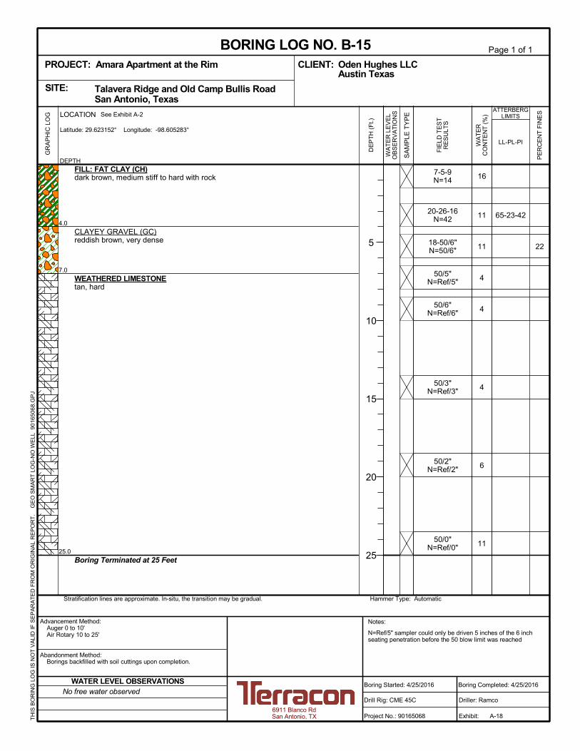
N=Ref/5" sampler could only be driven 5 inches of the 6 inchseating penetration before the 50 blow limit was reached
22
16
11
11
4
4
4
6
11
65-23-42
7-5-9N=14
20-26-16N=42
18-50/6"N=50/6"
50/5"N=Ref/5"
50/6"N=Ref/6"
50/3"N=Ref/3"
50/2"N=Ref/2"
50/0"N=Ref/0"
4.0
7.0
25.0
FILL: FAT CLAY (CH)dark brown, medium stiff to hard with rock
CLAYEY GRAVEL (GC)reddish brown, very dense
WEATHERED LIMESTONEtan, hard
Boring Terminated at 25 Feet
Hammer Type: AutomaticStratification lines are approximate. In-situ, the transition may be gradual.
GR
AP
HIC
LO
G
TH
IS B
OR
ING
LO
G IS
NO
T V
ALI
D IF
SE
PA
RA
TE
D F
RO
M O
RIG
INA
L R
EP
OR
T.
G
EO
SM
AR
T L
OG
-NO
WE
LL 9
016
506
8.G
PJ
Talavera Ridge and Old Camp Bullis Road San Antonio, TexasSITE:
Page 1 of 1
Advancement Method:Auger 0 to 10'Air Rotary 10 to 25'
Abandonment Method:Borings backfilled with soil cuttings upon completion.
6911 Blanco RdSan Antonio, TX
Notes:
Project No.: 90165068
Drill Rig: CME 45C
Boring Started: 4/25/2016
BORING LOG NO. B-15Oden Hughes LLCCLIENT:Austin Texas
Driller: Ramco
Boring Completed: 4/25/2016
Exhibit: A-18
PROJECT: Amara Apartment at the Rim
PE
RC
EN
T F
INE
S
WA
TE
RC
ON
TE
NT
(%
)
ATTERBERGLIMITS
LL-PL-PI
SA
MP
LE T
YP
E
WA
TE
R L
EV
EL
OB
SE
RV
AT
ION
S
DE
PT
H (
Ft.)
5
10
15
20
25
FIE
LD T
ES
TR
ES
ULT
S
DEPTH
LOCATION See Exhibit A-2
Latitude: 29.623152° Longitude: -98.605283°
No free water observedWATER LEVEL OBSERVATIONS

N=Ref/2" sampler could only be driven 2 inch of the 6 inchseating penetration before the 50 blow limit was reached
57
19
16
16
8
7
3
4
7
8
8
43-21-22
33-19-14
11-7-4N=11
25-50/5"N=50/5"
50/2"N=Ref/2"
30-37-39N=76
31-50/5"N=50/5"
50/0"N=Ref/0"
50/0"N=Ref/0"
50/0"N=Ref/0"
2.0
11.0
25.0
FILL: LEAN CLAY (CL)dark brown, stiff, sandy with gravel
CLAYEY GRAVEL (GC)reddish brown, very dense
WEATHERED LIMESTONEtan, hard
- turns to gray below 18 feet
Boring Terminated at 25 Feet
Hammer Type: AutomaticStratification lines are approximate. In-situ, the transition may be gradual.
GR
AP
HIC
LO
G
TH
IS B
OR
ING
LO
G IS
NO
T V
ALI
D IF
SE
PA
RA
TE
D F
RO
M O
RIG
INA
L R
EP
OR
T.
G
EO
SM
AR
T L
OG
-NO
WE
LL 9
016
506
8.G
PJ
Talavera Ridge and Old Camp Bullis Road San Antonio, TexasSITE:
Page 1 of 1
Advancement Method:Auger 0 to 10'Air Rotary 10 to 25'
Abandonment Method:Borings backfilled with soil cuttings upon completion.
6911 Blanco RdSan Antonio, TX
Notes:
Project No.: 90165068
Drill Rig: CME 45C
Boring Started: 6/10/2016
BORING LOG NO. B-16Oden Hughes LLCCLIENT:Austin Texas
Driller: Ramco
Boring Completed: 6/10/2016
Exhibit: A-19
PROJECT: Amara Apartment at the Rim
PE
RC
EN
T F
INE
S
WA
TE
RC
ON
TE
NT
(%
)
ATTERBERGLIMITS
LL-PL-PI
SA
MP
LE T
YP
E
WA
TE
R L
EV
EL
OB
SE
RV
AT
ION
S
DE
PT
H (
Ft.)
5
10
15
20
25
FIE
LD T
ES
TR
ES
ULT
S
DEPTH
LOCATION See Exhibit A-2
Latitude: 29.623197° Longitude: -98.605089°
No free water observedWATER LEVEL OBSERVATIONS
N=Ref/3" sampler could only be driven 3 inch of the 6 inchseating penetration before the 50 blow limit was reached
88
20
9
33
18
7
8
8
8
6
82-35-47
NP
8-7-10N=17
6-6-5N=11
6-11-15N=26
26-19-25N=44
21-15-9N=24
50/2"N=Ref/2"
19-50/2"N=50/2"
50/3"N=Ref/3"
6.0
12.0
25.0
FILL: FAT CLAY (CH)dark brown, stiff to very stiff, gravelly at the surface
CLAYEY GRAVEL (GC)reddish brown, medium dense to dense
WEATHERED LIMESTONEtan, hard
Boring Terminated at 25 Feet
Hammer Type: AutomaticStratification lines are approximate. In-situ, the transition may be gradual.
GR
AP
HIC
LO
G
TH
IS B
OR
ING
LO
G IS
NO
T V
ALI
D IF
SE
PA
RA
TE
D F
RO
M O
RIG
INA
L R
EP
OR
T.
G
EO
SM
AR
T L
OG
-NO
WE
LL 9
016
506
8.G
PJ
Talavera Ridge and Old Camp Bullis Road San Antonio, TexasSITE:
Page 1 of 1
Advancement Method:Auger 0 to 10'Air Rotary 10 to 25'
Abandonment Method:Borings backfilled with soil cuttings upon completion.
6911 Blanco RdSan Antonio, TX
Notes:
Project No.: 90165068
Drill Rig: CME 45C
Boring Started: 6/10/2016
BORING LOG NO. B-17Oden Hughes LLCCLIENT:Austin Texas
Driller: Ramco
Boring Completed: 6/10/2016
Exhibit: A-20
PROJECT: Amara Apartment at the Rim
PE
RC
EN
T F
INE
S
WA
TE
RC
ON
TE
NT
(%
)
ATTERBERGLIMITS
LL-PL-PI
SA
MP
LE T
YP
E
WA
TE
R L
EV
EL
OB
SE
RV
AT
ION
S
DE
PT
H (
Ft.)
5
10
15
20
25
FIE
LD T
ES
TR
ES
ULT
S
DEPTH
LOCATION See Exhibit A-2
Latitude: 29.62274° Longitude: -98.604122°
No free water observedWATER LEVEL OBSERVATIONS

N=Ref/2" sampler could only be driven 2 inches of the 6 inchseating penetration before the 50 blow limit was reached
53
31
13
16
13
17
8
8
8
33-21-12
53-25-28
4-3-4N=7
8-12-10N=22
4-3-3N=6
8-12-12N=24
47-50/1"N=50/1"
50/2"N=Ref/2"
50/2"N=Ref/2"
50/0"N=Ref/0"
6.0
8.0
13.0
25.0
FILL: LEAN CLAY (CL)dark brown, medium stiff to very stiff, gravelly
FAT CLAY (CH)brown, very stiff
CLAYEY GRAVEL (GC)reddish brown, very dense
WEATHERED LIMESTONEtan, hard
Boring Terminated at 25 Feet
Hammer Type: AutomaticStratification lines are approximate. In-situ, the transition may be gradual.
GR
AP
HIC
LO
G
TH
IS B
OR
ING
LO
G IS
NO
T V
ALI
D IF
SE
PA
RA
TE
D F
RO
M O
RIG
INA
L R
EP
OR
T.
G
EO
SM
AR
T L
OG
-NO
WE
LL 9
016
506
8.G
PJ
Talavera Ridge and Old Camp Bullis Road San Antonio, TexasSITE:
Page 1 of 1
Advancement Method:Auger 0 to 10'Air Rotary 10 to 25'
Abandonment Method:Borings backfilled with soil cuttings upon completion.
6911 Blanco RdSan Antonio, TX
Notes:
Project No.: 90165068
Drill Rig: CME 45C
Boring Started: 5/6/2016
BORING LOG NO. B-18Oden Hughes LLCCLIENT:Austin Texas
Driller: Ramco
Boring Completed: 5/6/2016
Exhibit: A-21
PROJECT: Amara Apartment at the Rim
PE
RC
EN
T F
INE
S
WA
TE
RC
ON
TE
NT
(%
)
ATTERBERGLIMITS
LL-PL-PI
SA
MP
LE T
YP
E
WA
TE
R L
EV
EL
OB
SE
RV
AT
ION
S
DE
PT
H (
Ft.)
5
10
15
20
25
FIE
LD T
ES
TR
ES
ULT
S
DEPTH
LOCATION See Exhibit A-2
Latitude: 29.62234° Longitude: -98.60414°
No free water observedWATER LEVEL OBSERVATIONS

N=Ref/4" sampler could only be driven 4 inches of the 6 inchseating penetration before the 50 blow limit was reached
34
24
20
10
11
7
4
11
59-26-33
28-16-12
28-14-14
4-5-4N=9
6-22-26N=48
8-12-25N=37
30-50/5"N=50/5"
31-29-38N=67
50/4"N=Ref/4"
3.0
12.0
15.0
FILL: CLAYEY GRAVEL (GC)dark brown, loose
CLAYEY GRAVEL (GC)reddish brown, dense to very dense
WEATHERED LIMESTONEtan, hard
Boring Terminated at 15 Feet
Hammer Type: AutomaticStratification lines are approximate. In-situ, the transition may be gradual.
GR
AP
HIC
LO
G
TH
IS B
OR
ING
LO
G IS
NO
T V
ALI
D IF
SE
PA
RA
TE
D F
RO
M O
RIG
INA
L R
EP
OR
T.
G
EO
SM
AR
T L
OG
-NO
WE
LL 9
016
506
8.G
PJ
Talavera Ridge and Old Camp Bullis Road San Antonio, TexasSITE:
Page 1 of 1
Advancement Method:Auger 0 to 10'Air Rotary 10 to 15'
Abandonment Method:Borings backfilled with soil cuttings upon completion.
6911 Blanco RdSan Antonio, TX
Notes:
Project No.: 90165068
Drill Rig: CME 45C
Boring Started: 6/10/2016
BORING LOG NO. B-19Oden Hughes LLCCLIENT:Austin Texas
Driller: Ramco
Boring Completed: 6/10/2016
Exhibit: A-22
PROJECT: Amara Apartment at the Rim
PE
RC
EN
T F
INE
S
WA
TE
RC
ON
TE
NT
(%
)
ATTERBERGLIMITS
LL-PL-PI
SA
MP
LE T
YP
E
WA
TE
R L
EV
EL
OB
SE
RV
AT
ION
S
DE
PT
H (
Ft.)
5
10
15
FIE
LD T
ES
TR
ES
ULT
S
DEPTH
LOCATION See Exhibit A-2
Latitude: 29.622281° Longitude: -98.604126°
No free water observedWATER LEVEL OBSERVATIONS

N=Ref/4" sampler could only be driven 4 inches of the 6 inchseating penetration before the 50 blow limit was reached
42
20
10
8
21
9
7
8
9
30-15-15
23-16-7
8-17-15N=32
8-8-8N=16
11-20-9N=29
16-21-32N=53
35-39-27N=66
9-50/2"N=50/2"
50/4"N=Ref/4"
4.0
16.0
20.0
FILL: LEAN CLAY (CL)dark brown, very stiff to hard, gravelly
CLAYEY GRAVEL (GC)brown, medium dense to very dense
WEATHERED LIMESTONEtan, hard
Boring Terminated at 20 Feet
Hammer Type: AutomaticStratification lines are approximate. In-situ, the transition may be gradual.
GR
AP
HIC
LO
G
TH
IS B
OR
ING
LO
G IS
NO
T V
ALI
D IF
SE
PA
RA
TE
D F
RO
M O
RIG
INA
L R
EP
OR
T.
G
EO
SM
AR
T L
OG
-NO
WE
LL 9
016
506
8.G
PJ
Talavera Ridge and Old Camp Bullis Road San Antonio, TexasSITE:
Page 1 of 1
Advancement Method:Auger 0 to 10'Air Rotary 10 to 20'
Abandonment Method:Borings backfilled with soil cuttings upon completion.
6911 Blanco RdSan Antonio, TX
Notes:
Project No.: 90165068
Drill Rig: CME 45C
Boring Started: 6/10/2016
BORING LOG NO. B-20Oden Hughes LLCCLIENT:Austin Texas
Driller: Ramco
Boring Completed: 6/10/2016
Exhibit: A-23
PROJECT: Amara Apartment at the Rim
PE
RC
EN
T F
INE
S
WA
TE
RC
ON
TE
NT
(%
)
ATTERBERGLIMITS
LL-PL-PI
SA
MP
LE T
YP
E
WA
TE
R L
EV
EL
OB
SE
RV
AT
ION
S
DE
PT
H (
Ft.)
5
10
15
20
FIE
LD T
ES
TR
ES
ULT
S
DEPTH
LOCATION See Exhibit A-2
Latitude: 29.622744° Longitude: -98.604835°
No free water observedWATER LEVEL OBSERVATIONS

4.0
5.0
6.0
FILL - CLAYEY GRAVEL WITH SAND (GC)light brown and brown, with boulders
FILL - FAT CLAY (CH)dark brown, with gravel
CLAYEY GRAVEL WITH SAND (GC)reddish brown
Test Pit Terminated at 6 Feet
Stratification lines are approximate. In-situ, the transition may be gradual.
GR
AP
HIC
LO
G
TH
IS B
OR
ING
LO
G IS
NO
T V
ALI
D IF
SE
PA
RA
TE
D F
RO
M O
RIG
INA
L R
EP
OR
T.
GE
O S
MA
RT
LO
G-N
O W
ELL
901
552
70.G
PJ
Talavera Ridge & Old Camp Bullis Road San Antonio, TexasSITE:
Page 1 of 1
Advancement Method:
Abandonment Method:Backfilled with on-site soil
6911 Blanco RoadSan Antonio, Texas
Notes:
Project No.: 90155270
Excavator: backhoe
Test Pit Started: 12/9/2016
TEST PIT LOG NO. TP-1Oden Hughes Multifamily Development &CLIENT:Construction
Operator:
Test Pit Completed: 12/9/2016
Exhibit: A-24
Austin, Texas
PROJECT: Amara Apartments
PE
RC
EN
T F
INE
S
WA
TE
RC
ON
TE
NT
(%
)
ATTERBERGLIMITS
LL-PL-PI
SA
MP
LE T
YP
E
WA
TE
R L
EV
EL
OB
SE
RV
AT
ION
S
DE
PT
H (
Ft.)
5
FIE
LD T
ES
TR
ES
ULT
S
DEPTH
LOCATION See Exhibit A-2
Latitude: 29.622495° Longitude: -98.60389°
WATER LEVEL OBSERVATIONS

5.0
6.0
FILL -FAT CLAY (CH)dark brown brown and brown, with cobbles, boulders, wood, and metal debris
CLAYEY GRAVEL WITH SAND (GC)reddish brown
Test Pit Terminated at 6 Feet
Stratification lines are approximate. In-situ, the transition may be gradual.
GR
AP
HIC
LO
G
TH
IS B
OR
ING
LO
G IS
NO
T V
ALI
D IF
SE
PA
RA
TE
D F
RO
M O
RIG
INA
L R
EP
OR
T.
GE
O S
MA
RT
LO
G-N
O W
ELL
901
552
70.G
PJ
Talavera Ridge & Old Camp Bullis Road San Antonio, TexasSITE:
Page 1 of 1
Advancement Method:
Abandonment Method:Backfilled with on-site soil
6911 Blanco RoadSan Antonio, Texas
Notes:
Project No.: 90155270
Excavator: backhoe
Test Pit Started: 12/9/2016
TEST PIT LOG NO. TP-2Oden Hughes Multifamily Development &CLIENT:Construction
Operator:
Test Pit Completed: 12/9/2016
Exhibit: A-25
Austin, Texas
PROJECT: Amara Apartments
PE
RC
EN
T F
INE
S
WA
TE
RC
ON
TE
NT
(%
)
ATTERBERGLIMITS
LL-PL-PI
SA
MP
LE T
YP
E
WA
TE
R L
EV
EL
OB
SE
RV
AT
ION
S
DE
PT
H (
Ft.)
5
FIE
LD T
ES
TR
ES
ULT
S
DEPTH
LOCATION See Exhibit A-2
Latitude: 29.622815° Longitude: -98.604765°
WATER LEVEL OBSERVATIONS

6.0
7.0
FILL - CLAYEY GRAVEL WITH SAND (GC)light brown, with boulders
CLAYEY GRAVEL WITH SAND (GC)reddish brown
Test Pit Terminated at 7 Feet
Stratification lines are approximate. In-situ, the transition may be gradual.
GR
AP
HIC
LO
G
TH
IS B
OR
ING
LO
G IS
NO
T V
ALI
D IF
SE
PA
RA
TE
D F
RO
M O
RIG
INA
L R
EP
OR
T.
GE
O S
MA
RT
LO
G-N
O W
ELL
901
552
70.G
PJ
Talavera Ridge & Old Camp Bullis Road San Antonio, TexasSITE:
Page 1 of 1
Advancement Method:
Abandonment Method:Backfilled with on-site soil
6911 Blanco RoadSan Antonio, Texas
Notes:
Project No.: 90155270
Excavator: backhoe
Test Pit Started: 12/9/2016
TEST PIT LOG NO. TP-3Oden Hughes Multifamily Development &CLIENT:Construction
Operator:
Test Pit Completed: 12/9/2016
Exhibit: A-26
Austin, Texas
PROJECT: Amara Apartments
PE
RC
EN
T F
INE
S
WA
TE
RC
ON
TE
NT
(%
)
ATTERBERGLIMITS
LL-PL-PI
SA
MP
LE T
YP
E
WA
TE
R L
EV
EL
OB
SE
RV
AT
ION
S
DE
PT
H (
Ft.)
5
FIE
LD T
ES
TR
ES
ULT
S
DEPTH
LOCATION See Exhibit A-2
Latitude: 29.622997° Longitude: -98.605743°
WATER LEVEL OBSERVATIONS

APPENDIX B

Geotechnical Engineering Report
Amara Apartments at the Rim ■ San Antonio, Texas
June 27, 2016 ■ Terracon Project No. 90165068
Reliable ■ Resourceful ■ Responsive Exhibit B-1
Laboratory Testing
Samples retrieved during the field exploration were taken to the laboratory for further observation
by the project geotechnical engineer and were classified in accordance with the Unified Soil
Classification System (USCS) described in this Appendix. At that time, the field descriptions were
confirmed or modified as necessary and an applicable laboratory testing program was formulated
to determine engineering properties of the subsurface materials.
Laboratory tests were conducted on selected soil samples and the test results are presented in
this appendix. The laboratory test results were used for the geotechnical engineering analyses,
and the development of foundation and earthwork recommendations. Laboratory tests were
performed in general accordance with the applicable ASTM, local or other accepted standards.
Selected soil samples obtained from the site were tested for the following engineering properties:
Moisture Content
Atterberg Limits
Percent Passing the No. 200 Sieve
Sample Disposal
All samples were returned to our laboratory. The samples not tested in the laboratory will be
stored for a period of 30 days subsequent to submittal of this report and will be discarded after
this period, unless other arrangements are made prior to the disposal period.

APPENDIX C

PLASTICITY DESCRIPTION
Term
< 1515 - 29> 30
Descriptive Term(s)of other constituents
Water InitiallyEncountered
Water Level After aSpecified Period of Time
Major Componentof Sample
Percent ofDry Weight
(More than 50% retained on No. 200 sieve.)Density determined by Standard Penetration Resistance
Includes gravels, sands and silts.
Hard
Unconfined CompressiveStrength, Qu, tsf
Very Loose 0 - 3 0 - 6 Very Soft less than 0.25
7 - 18 Soft 0.25 to 0.50
10 - 29 19 - 58 0.50 to 1.00
59 - 98 Stiff 1.00 to 2.00
> 99 2.00 to 4.00
LOCATION AND ELEVATION NOTES
SA
MP
LIN
G
FIE
LD
TE
ST
S
(HP)
(T)
(b/f)
(PID)
(OVA)
DESCRIPTION OF SYMBOLS AND ABBREVIATIONS
Descriptive Term(Density)
Non-plasticLowMediumHigh
BouldersCobblesGravelSandSilt or Clay
10 - 18
> 50 15 - 30 19 - 42
> 30 > 42
_
Hand Penetrometer
Torvane
Standard PenetrationTest (blows per foot)
Photo-Ionization Detector
Organic Vapor Analyzer
Water levels indicated on the soil boringlogs are the levels measured in theborehole at the times indicated.Groundwater level variations will occurover time. In low permeability soils,accurate determination of groundwaterlevels is not possible with short termwater level observations.
CONSISTENCY OF FINE-GRAINED SOILS
(50% or more passing the No. 200 sieve.)Consistency determined by laboratory shear strength testing, field
visual-manual procedures or standard penetration resistance
DESCRIPTIVE SOIL CLASSIFICATION
Unless otherwise noted, Latitude and Longitude are approximately determined using a hand-held GPS device. The accuracyof such devices is variable. Surface elevation data annotated with +/- indicates that no actual topographical survey wasconducted to confirm the surface elevation. Instead, the surface elevation was approximately determined from topographicmaps of the area.
Soil classification is based on the Unified Soil Classification System. Coarse Grained Soils have more than 50% of their dryweight retained on a #200 sieve; their principal descriptors are: boulders, cobbles, gravel or sand. Fine Grained Soils haveless than 50% of their dry weight retained on a #200 sieve; they are principally described as clays if they are plastic, andsilts if they are slightly plastic or non-plastic. Major constituents may be added as modifiers and minor constituents may beadded according to the relative proportions based on grain size. In addition to gradation, coarse-grained soils are definedon the basis of their in-place relative density and fine-grained soils on the basis of their consistency.
Plasticity Index
01 - 1011 - 30
> 30
RELATIVE PROPORTIONS OF FINES
Descriptive Term(s)of other constituents
Percent ofDry Weight
< 55 - 12> 12
TraceWithModifier
Water Level Aftera Specified Period of Time
GRAIN SIZE TERMINOLOGYRELATIVE PROPORTIONS OF SAND AND GRAVEL
TraceWithModifier
Standard Penetration orN-Value
Blows/Ft.
Descriptive Term(Consistency)
Loose
Very Stiff
Standard Penetration orN-Value
Blows/Ft.
Ring SamplerBlows/Ft.
Ring SamplerBlows/Ft.
Medium Dense
Dense
Very Dense
0 - 1 < 3
4 - 9 2 - 4 3 - 4
Medium-Stiff
8 - 15
Exhibit C-1
5 - 9
30 - 50
WA
TE
R L
EV
EL
Auger
Shelby Tube
Ring Sampler
Grab Sample
Split Spoon
Macro Core
Rock Core
No Recovery
RELATIVE DENSITY OF COARSE-GRAINED SOILS
Particle Size
Over 12 in. (300 mm)12 in. to 3 in. (300mm to 75mm)3 in. to #4 sieve (75mm to 4.75 mm)#4 to #200 sieve (4.75mm to 0.075mmPassing #200 sieve (0.075mm)
ST
RE
NG
TH
TE
RM
S
> 4.00
4 - 8
GENERAL NOTES

Exhibit C-2
UNIFIED SOIL CLASSIFICATION SYSTEM
Criteria for Assigning Group Symbols and Group Names Using Laboratory Tests A
Soil Classification
Group
Symbol Group Name
B
Coarse Grained Soils:
More than 50% retained
on No. 200 sieve
Gravels:
More than 50% of
coarse fraction retained
on No. 4 sieve
Clean Gravels:
Less than 5% fines C
Cu 4 and 1 Cc 3 E
GW Well-graded gravel F
Cu 4 and/or 1 Cc 3 E
GP Poorly graded gravel F
Gravels with Fines:
More than 12% fines C
Fines classify as ML or MH GM Silty gravel F,G,H
Fines classify as CL or CH GC Clayey gravel F,G,H
Sands:
50% or more of coarse
fraction passes No. 4
sieve
Clean Sands:
Less than 5% fines D
Cu 6 and 1 Cc 3 E
SW Well-graded sand I
Cu 6 and/or 1 Cc 3 E
SP Poorly graded sand I
Sands with Fines:
More than 12% fines D
Fines classify as ML or MH SM Silty sand G,H,I
Fines classify as CL or CH SC Clayey sand G,H,I
Fine-Grained Soils:
50% or more passes the
No. 200 sieve
Silts and Clays:
Liquid limit less than 50
Inorganic: PI 7 and plots on or above “A” line
J CL Lean clay
K,L,M
PI 4 or plots below “A” line J ML Silt
K,L,M
Organic: Liquid limit - oven dried
0.75 OL Organic clay
K,L,M,N
Liquid limit - not dried Organic silt K,L,M,O
Silts and Clays:
Liquid limit 50 or more
Inorganic: PI plots on or above “A” line CH Fat clay
K,L,M
PI plots below “A” line MH Elastic Silt K,L,M
Organic: Liquid limit - oven dried
0.75 OH Organic clay
K,L,M,P
Liquid limit - not dried Organic silt K,L,M,Q
Highly organic soils: Primarily organic matter, dark in color, and organic odor PT Peat
A Based on the material passing the 3-inch (75-mm) sieve
B If field sample contained cobbles or boulders, or both, add “with cobbles
or boulders, or both” to group name. C
Gravels with 5 to 12% fines require dual symbols: GW-GM well-graded
gravel with silt, GW-GC well-graded gravel with clay, GP-GM poorly
graded gravel with silt, GP-GC poorly graded gravel with clay. D
Sands with 5 to 12% fines require dual symbols: SW-SM well-graded
sand with silt, SW-SC well-graded sand with clay, SP-SM poorly graded
sand with silt, SP-SC poorly graded sand with clay
E Cu = D60/D10 Cc =
6010
2
30
DxD
)(D
F If soil contains 15% sand, add “with sand” to group name.
G If fines classify as CL-ML, use dual symbol GC-GM, or SC-SM.
H If fines are organic, add “with organic fines” to group name.
I If soil contains 15% gravel, add “with gravel” to group name.
J If Atterberg limits plot in shaded area, soil is a CL-ML, silty clay.
K If soil contains 15 to 29% plus No. 200, add “with sand” or “with gravel,”
whichever is predominant. L
If soil contains 30% plus No. 200 predominantly sand, add “sandy” to
group name. M
If soil contains 30% plus No. 200, predominantly gravel, add
“gravelly” to group name. N
PI 4 and plots on or above “A” line. O
PI 4 or plots below “A” line. P
PI plots on or above “A” line. Q
PI plots below “A” line.