Embed Size (px)
Citation preview
REPORT C OVER PAGE
Geotechnical Engineering Report __________________________________________________________________________
Temecula Flood Control Channel Recon and Repair
Temecula, California
October 4, 2019
Terracon Project No. 60195071
Prepared for:
Fullerton, California
Prepared by:
Terracon Consultants, Inc.
Tustin, California
Responsive Resourceful Reliable 1
REPORT TOPICS
INTRODUCTION ............................................................................................................. 1
SITE CONDITIONS ......................................................................................................... 1 PROJECT DESCRIPTION .............................................................................................. 2 GEOTECHNICAL CHARACTERIZATION ...................................................................... 3 SEISMIC CONSIDERATIONS ........................................................................................ 4 LIQUEFACTION ............................................................................................................. 5
CORROSIVITY ............................................................................................................... 5 GEOTECHNICAL OVERVIEW ....................................................................................... 6 EARTHWORK ................................................................................................................ 6 LATERAL EARTH PRESSURES ................................................................................. 10
GENERAL COMMENTS ............................................................................................... 11
ATTACHMENTS
EXPLORATION AND TESTING PROCEDURES
SITE LOCATION AND EXPLORATION PLANS
EXPLORATION RESULTS (Boring Logs and Laboratory Data)
SUPPORTING INFORMATION (General Notes and Unified Soil Classification System)
Responsive Resourceful Reliable 1
INTRODUCTION
Geotechnical Engineering Report
Temecula Flood Control Channel Recon and Repair
44900 Temecula Lane
Temecula, California Terracon Project No. 60195071
October 4, 2019
INTRODUCTION
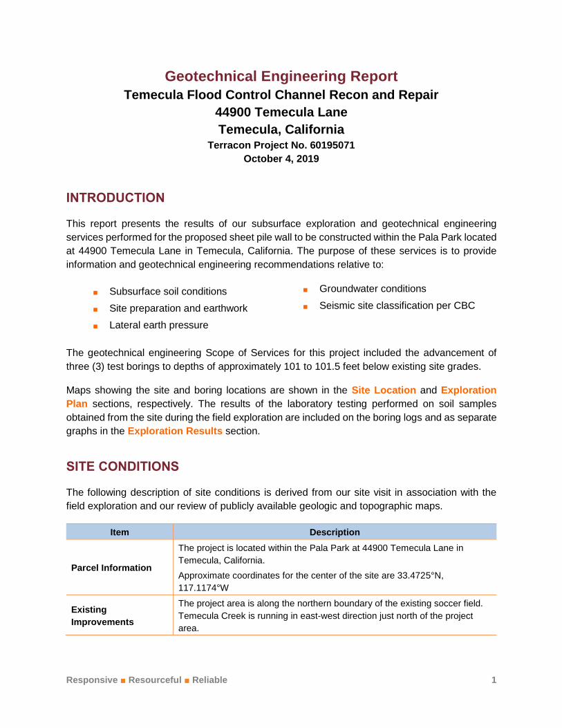
This report presents the results of our subsurface exploration and geotechnical engineering
services performed for the proposed sheet pile wall to be constructed within the Pala Park located
at 44900 Temecula Lane in Temecula, California. The purpose of these services is to provide
information and geotechnical engineering recommendations relative to:
Subsurface soil conditions Groundwater conditions
Site preparation and earthwork Seismic site classification per CBC
Lateral earth pressure
The geotechnical engineering Scope of Services for this project included the advancement of
three (3) test borings to depths of approximately 101 to 101.5 feet below existing site grades.
Maps showing the site and boring locations are shown in the Site Location and Exploration
Plan sections, respectively. The results of the laboratory testing performed on soil samples
obtained from the site during the field exploration are included on the boring logs and as separate
graphs in the Exploration Results section.
SITE CONDITIONS
The following description of site conditions is derived from our site visit in association with the
field exploration and our review of publicly available geologic and topographic maps.
Item Description
Parcel Information
The project is located within the Pala Park at 44900 Temecula Lane in
Temecula, California.
Approximate coordinates for the center of the site are 33.4725°N,
117.1174°W
Existing
Improvements
The project area is along the northern boundary of the existing soccer field.
Temecula Creek is running in east-west direction just north of the project
area.

Geotechnical Engineering Report
Temecula Flood Control Channel Recon and Repair Temecula, California
October 4, 2019 Terracon Project No. 60195071
Responsive Resourceful Reliable 2
Item Description
Current Ground
Cover Exposed soils and vegetation
Existing Topography
(from google earth)
The site is relatively flat and has an approximate elevation ranging between
1014 and 1015 feet above mean sea level.
Geology
The site is situated within the Peninsular Ranges Geomorphic Province in
Southern California. Geologic structures within this Province trend mostly
northwest, in contrast to the prevailing east-west trend in the neighboring
Transverse Ranges Geomorphic Province to the north. The Peninsular
Range Province extends into lower California and is bounded by the
Colorado Desert to the east, the Pacific Ocean to the west and the San
Gabriel and San Bernardino mountains to the north. 1,2 Surficial geologic
units mapped at the site consists of Quaternary aged recent alluvium3.
PROJECT DESCRIPTION
Item Description
Proposed Structures
The project will include installation of sheet pile wall and the sheet piles will
be driven to maximum depth of about 40-foot below ground surface (bgs).
The sheet piles will be driven to the ground entirely below the existing
ground surface. Based on the information provided by CWE, approximately
16 to 18 feet of scour/erosion of materials are anticipated due to water flow
along creek. Therefore, the sheet pile system will be designed as
cantilevered system with approximately 16 to 18 feet of retained soil height
and 22 to 24 feet of embedded depth.
Construction
The sheet piles are anticipated to be driven steel W Sections and these
sheet piles are anticipated to retain approximately 16 to 18 feet of soil on the
southside of the wall.
Top of Sheet Pile Elevation (from google earth)
The existing ground surface elevation is approximately 1015 feet and top of
the sheet pile wall is anticipated to be at the same elevation of 1015 feet.
Grading Minimal cut – assumed to be less than one foot. New fills are not anticipated.
1 Harden, D. R., “California Geology, Second Edition,” Pearson Prentice Hall, 2004. 2 Norris, R. M. and Webb, R. W., “Geology of California, Second Edition,” John Wiley & Sons, Inc., 1990. 3 Division of Mines and Geology, “Geologic Map of California, Olaf P. Jenkins Edition, Santa Ana Sheet”, Compilation by Thomas H.
Rogers, 1965, Second Edition 1973, Scale 1:250,000.

Geotechnical Engineering Report
Temecula Flood Control Channel Recon and Repair Temecula, California
October 4, 2019 Terracon Project No. 60195071
Responsive Resourceful Reliable 3
GEOTECHNICAL CHARACTERIZATION
We have developed a general characterization of the subsurface soil and groundwater conditions
based upon our review of the data and our understanding of the geologic setting and planned
construction. The following table provides our geotechnical characterization.
The geotechnical characterization forms the basis of our geotechnical calculations and evaluation
of site preparation and foundation options. As noted in General Comments, the characterization
is based upon widely spaced exploration points across the site, and variations are likely.
Stratum
Approximate
Depth to Bottom
of Stratum (feet)
Material Description Consistency/
Density
1 20 Sand with variable amounts of silt Loose to
medium dense
2 30 Sand with variable amounts of silt and gravel Dense to very
dense
3 40 Sand with variable amounts of silt and gravel and clay
and silt with variable amounts of sand and gravel
Very
dense/Hard
4 Boring termination
at 101.5 Sand and gravel with variable amounts of silt Very dense
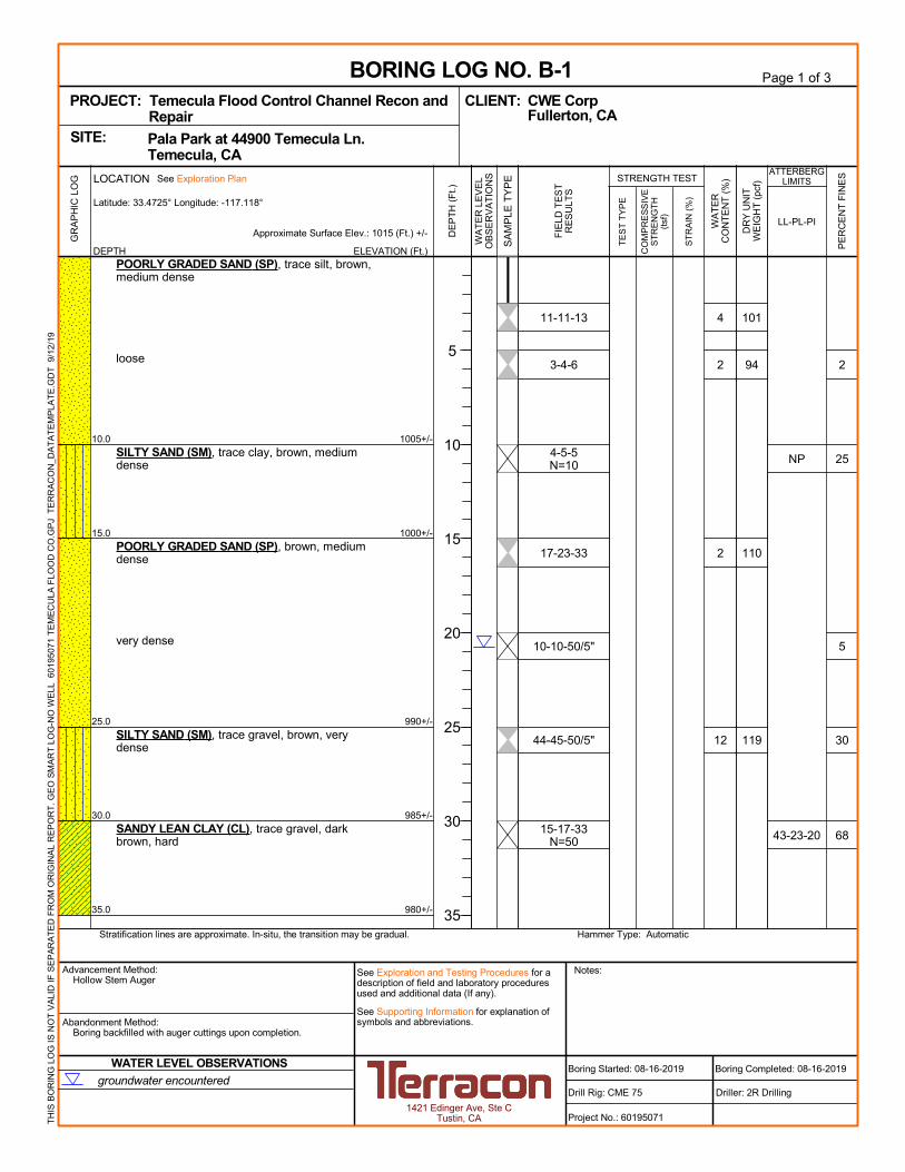
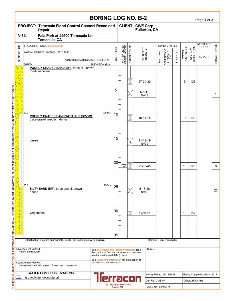
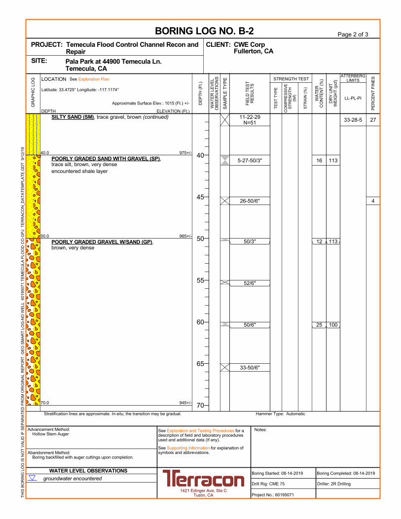
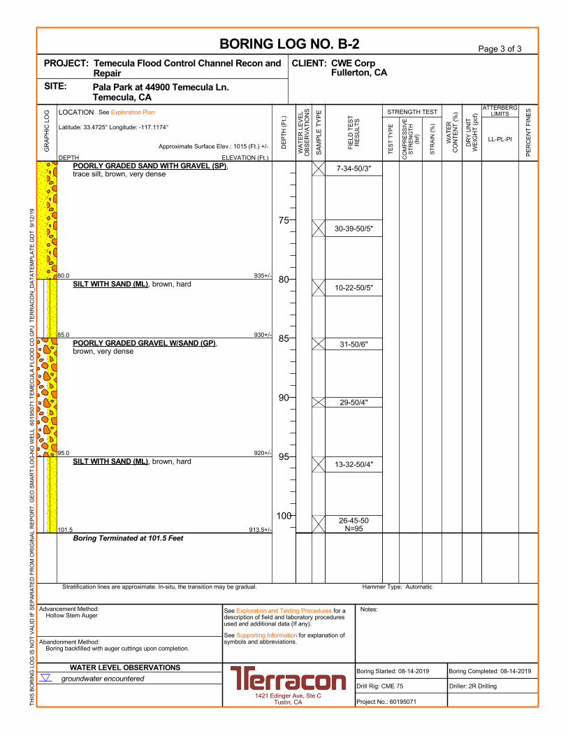
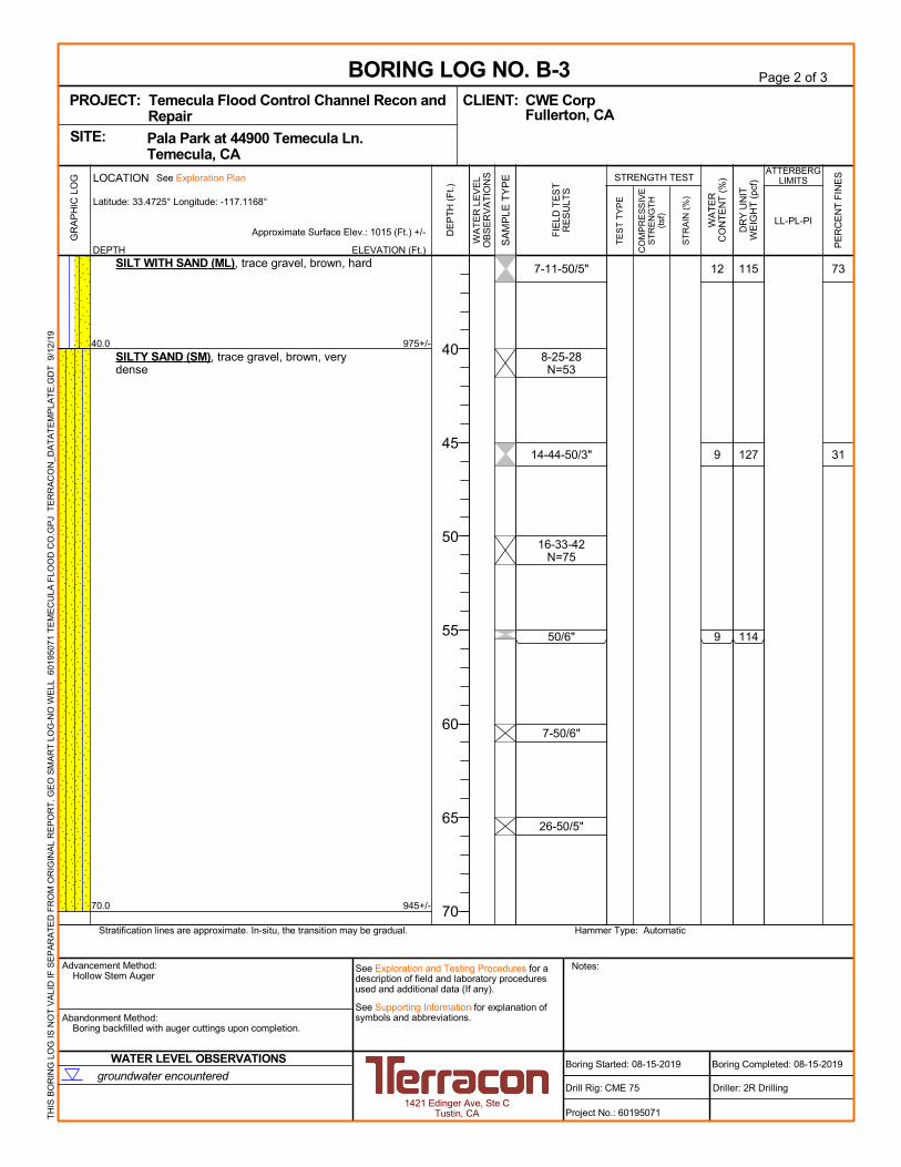
Conditions encountered at each boring location are indicated on the individual boring logs shown
in the Exploration Results section and are attached to this report. Stratification boundaries on
the boring logs represent the approximate location of changes in native soil types; in situ, the
transition between materials may be gradual.
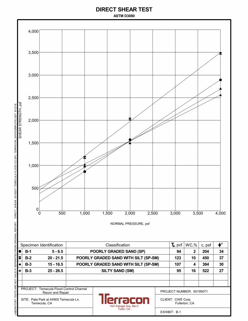
Lab Results
Laboratory tests were conducted on selected soil samples and the test results are presented in
the Exploration Results section and on the boring logs. Atterberg limit test results indicate that
the on-site soils generally are non-plastic except for the clay and silt layers which have low to
moderate plasticity. Direct Shear tests performed on samples taken at various depths between 5
and 25 feet bgs indicate these soils have cohesion values ranging between 204 and 522 psf and
effective friction angles ranging between 27° and 37°.
Groundwater
Groundwater was observed in the borings between the depths of 20.5 and 22.5 feet, or for the short
duration the boring remained open. These observations represent groundwater conditions at the
time of the field exploration and may not be indicative of other times, or at other locations.
Groundwater level fluctuations occur due to seasonal variations in the amount of rainfall, runoff
and other factors not evident at the time the borings were performed. Therefore, groundwater
Geotechnical Engineering Report
Temecula Flood Control Channel Recon and Repair Temecula, California
October 4, 2019 Terracon Project No. 60195071
Responsive Resourceful Reliable 4
levels during construction or at other times in the life of the structure may be higher or lower than
the levels indicated on the boring logs. The possibility of groundwater level fluctuations should be
considered when developing the design and construction plans for the project.
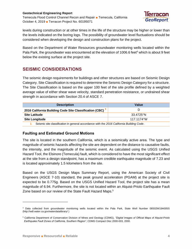
Based on the Department of Water Resources groundwater monitoring wells located within the
Pala Park, the groundwater was encountered at the elevation of 1006.6 feet4 which is about 9 feet
below the existing surface at the project site.
SEISMIC CONSIDERATIONS
The seismic design requirements for buildings and other structures are based on Seismic Design
Category. Site Classification is required to determine the Seismic Design Category for a structure.
The Site Classification is based on the upper 100 feet of the site profile defined by a weighted
average value of either shear wave velocity, standard penetration resistance, or undrained shear
strength in accordance with Section 20.4 of ASCE 7.
Description Value
2016 California Building Code Site Classification (CBC) 1 D
Site Latitude 33.4725°N
Site Longitude 117.1174°W
1. Seismic site classification in general accordance with the 2016 California Building Code.
Faulting and Estimated Ground Motions
The site is located in the southern California, which is a seismically active area. The type and
magnitude of seismic hazards affecting the site are dependent on the distance to causative faults,
the intensity, and the magnitude of the seismic event. As calculated using the USGS Unified
Hazard Tool, the Elsinore (Temecula) fault, which is considered to have the most significant effect
at the site from a design standpoint, has a maximum credible earthquake magnitude of 7.23 and
is located approximately 1.5 kilometers from the site.
Based on the USGS Design Maps Summary Report, using the American Society of Civil
Engineers (ASCE 7-10) standard, the peak ground acceleration (PGAM) at the project site is
expected to be 0.775g. Based on the USGS Unified Hazard Tool, the project site has a mean
magnitude of 6.94. Furthermore, the site is not located within an Alquist-Priolo Earthquake Fault
Zone based on our review of the State Fault Hazard Maps.5
4 Data collected from groundwater monitoring wells located within the Pala Park, State Well Number 08S02W19A005S (http://wdl.water.ca.gov/waterdatalibrary/ )
5 California Department of Conservation Division of Mines and Geology (CDMG), “Digital Images of Official Maps of Alquist-Priolo
Earthquake Fault Zones of California, Southern Region”, CDMG Compact Disc 2000-003, 2000.

Geotechnical Engineering Report
Temecula Flood Control Channel Recon and Repair Temecula, California
October 4, 2019 Terracon Project No. 60195071
Responsive Resourceful Reliable 5
LIQUEFACTION
Liquefaction is a mode of ground failure that results from the generation of high pore water
pressures during earthquake ground shaking, causing loss of shear strength. Liquefaction is
typically a hazard where loose sandy soils exist below groundwater. The California Geological
Survey (CGS) and County of Riverside have designated certain areas as potential liquefaction
hazard zones. These are areas considered at a risk of liquefaction-related ground failure during
a seismic event, based upon mapped surficial deposits and the presence of a relatively shallow
water table.
The project site is mapped within a liquefaction hazard potential zone by the County of Riverside.
However, the proposed sheet piles are not supporting a human occupancy structure. Therefore,
liquefaction potential was not evaluated. Terracon should be notified if liquefaction should be
analyzed for this project.
CORROSIVITY
The table below lists the results of laboratory soluble sulfate, soluble chloride, electrical resistivity,
and pH testing. The values may be used to estimate potential corrosive characteristics of the on-
site soils with respect to contact with the various underground materials which will be used for
project construction.
Corrosivity Test Results Summary
Boring
Sample
Depth
(ft)
Soil
Description
Soluble
Sulfate
(%)
Sulfides
(ppm)
Chlorides
(ppm)
Red-Ox
Potential
(mV)
Electrical
Resistivity
(Ω-cm)
Total
Salts
(ppm)
pH
B-1 0 to 2.5
Poorly
Graded
Sand
0.02 Nil 27 +679 9,409 238 8.77
Results of soluble sulfate testing indicate, concrete should be designed in accordance with the
exposure class S0 provisions of the ACI Design Manual, Section 318, Chapter 19.
Geotechnical Engineering Report
Temecula Flood Control Channel Recon and Repair Temecula, California
October 4, 2019 Terracon Project No. 60195071
Responsive Resourceful Reliable 6
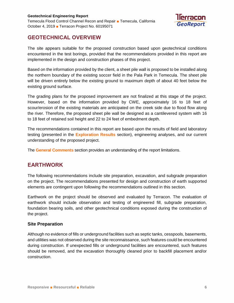
GEOTECHNICAL OVERVIEW
The site appears suitable for the proposed construction based upon geotechnical conditions
encountered in the test borings, provided that the recommendations provided in this report are
implemented in the design and construction phases of this project.
Based on the information provided by the client, a sheet pile wall is proposed to be installed along
the northern boundary of the existing soccer field in the Pala Park in Temecula. The sheet pile
will be driven entirely below the existing ground to maximum depth of about 40 feet below the
existing ground surface.
The grading plans for the proposed improvement are not finalized at this stage of the project.
However, based on the information provided by CWE, approximately 16 to 18 feet of
scour/erosion of the existing materials are anticipated on the creek side due to flood flow along
the river. Therefore, the proposed sheet pile wall be designed as a cantilevered system with 16
to 18 feet of retained soil height and 22 to 24 feet of embedment depth.
The recommendations contained in this report are based upon the results of field and laboratory
testing (presented in the Exploration Results section), engineering analyses, and our current
understanding of the proposed project.
The General Comments section provides an understanding of the report limitations.
EARTHWORK
The following recommendations include site preparation, excavation, and subgrade preparation
on the project. The recommendations presented for design and construction of earth supported
elements are contingent upon following the recommendations outlined in this section.
Earthwork on the project should be observed and evaluated by Terracon. The evaluation of
earthwork should include observation and testing of engineered fill, subgrade preparation,
foundation bearing soils, and other geotechnical conditions exposed during the construction of
the project.
Site Preparation
Although no evidence of fills or underground facilities such as septic tanks, cesspools, basements,
and utilities was not observed during the site reconnaissance, such features could be encountered
during construction. If unexpected fills or underground facilities are encountered, such features
should be removed, and the excavation thoroughly cleaned prior to backfill placement and/or
construction.

Geotechnical Engineering Report
Temecula Flood Control Channel Recon and Repair Temecula, California
October 4, 2019 Terracon Project No. 60195071
Responsive Resourceful Reliable 7
Subgrade Preparation
Based upon the subsurface conditions determined from the geotechnical exploration, subgrade
soils exposed during construction are anticipated to be relatively workable. However, the
workability of the subgrade may be affected by precipitation, repetitive construction traffic or other
factors. If unworkable conditions develop, workability may be improved by scarifying and drying.
Fill Materials and Placement
If required for planned grading, all fill materials should be inorganic soils free of vegetation, debris,
and fragments larger than 6 inches in size. Pea gravel or other similar non-cementatious, poorly-
graded materials should not be used as fill or backfill without the prior approval of the geotechnical
engineer.
Imported soils for use as fill material within proposed structure areas should conform to low
volume change materials as indicated in the following specifications:
Percent Finer by Weight
Gradation (ASTM C 136)
3” ......................................................................................................... 100
No. 4 Sieve ..................................................................................... 50-100
No. 200 Sieve ................................................................................... 10-40
◼ Liquid Limit ....................................................................... 30 (max)
◼ Plasticity Index ................................................................. 15 (max)
◼ Maximum expansion index* .............................................. 20 (max)
*ASTM D 4829
Engineered fill should be placed and compacted in horizontal lifts, using equipment and
procedures that will produce recommended moisture contents and densities throughout the lift.
Fill lifts should not exceed 10 inches loose thickness.
Compaction Requirements
Recommended compaction and moisture content criteria for fill materials are as follows:
Material Type and Location
Per the Modified Proctor Test (ASTM D 1557)
Minimum
Compaction
Requirement
Range of Moisture Contents for
Compaction Above Optimum
Minimum Maximum
Low volume change materials:
Utility trenches: 90% -1% +4%
Miscellaneous backfill: 90% 0% +3%

Geotechnical Engineering Report
Temecula Flood Control Channel Recon and Repair Temecula, California
October 4, 2019 Terracon Project No. 60195071
Responsive Resourceful Reliable 8
Grading and Drainage
Positive drainage should be provided during construction and maintained throughout the life of
the development. Infiltration of water into utility trenches should be prevented during construction.
Backfill against utility and sprinkler line trenches should be well compacted and free of all
construction debris to reduce the possibility of moisture infiltration.
Utility Trenches
It is anticipated that the on-site soils will provide suitable support for underground utilities and
piping that may be installed. Any soft and/or unsuitable material encountered at the bottom of
excavations should be removed and be replaced with an adequate bedding material. A non-
expansive granular material with a sand equivalent greater than 30 should be used for bedding
and shading of utilities, unless allowed or specified otherwise by the utility manufacturer.
On-site materials are considered suitable for backfill of utility and pipe trenches from one foot
above the top of the pipe to the final ground surface, provided the material is free of organic matter
and deleterious substances.
Trench backfill should be mechanically placed and compacted as discussed earlier in this report.
Compaction of initial lifts should be accomplished with hand-operated tampers or other lightweight
compactors. Where trenches are placed beneath slabs or footings, the backfill should satisfy the
gradation and expansion index requirements of engineered fill discussed in this report. Flooding
or jetting for placement and compaction of backfill is not recommended.
Construction Considerations
Based on the subsurface conditions encountered in the borings, dense to very dense sand and
gravel along with layers of hard fine-grained materials were encountered below the depth of about
30 feet below the existing ground surface. Based on this, difficult pile driving could be encountered
in these very dense granular or hard fine-grained materials. The contractor should select a driving
hammer suitable for the subsurface conditions. Furthermore, the contractor should select a driving
hammer and cushion combination that can install the selected piling without overstressing the pile
material. Considerations should be given to using protective points or flange stiffening.
The existing facility (structures and subsurface utilities) should be observed prior to pile
installation to document its condition. Structures should also be observed during pile installation
for indications of movement. Pile driving should be stopped, and Terracon contacted if movement
or cracking of the existing structures is observed. Monitoring vibration levels during pile driving
should be considered. Although vibrations from pile driving may be below levels that will cause
structural damage, they may be felt by occupants of the adjacent buildings. The potential impact
of driving piles at this site should be considered when evaluating this alternative.
Geotechnical Engineering Report
Temecula Flood Control Channel Recon and Repair Temecula, California
October 4, 2019 Terracon Project No. 60195071
Responsive Resourceful Reliable 9
The pile driving process should be performed under the direction of the Geotechnical Engineer.
The Geotechnical Engineer should document the pile installation process including soil/rock and
groundwater conditions encountered, consistency with expected conditions, and details of the
installed pile.
We recommend that the earthwork portion of this project be completed during extended periods
of dry weather if possible. If earthwork is completed during the wet season (typically November
through April) it may be necessary to take extra precautionary measures to protect subgrade soils.
Wet season earthwork operations may require additional mitigative measures beyond that which
would be expected during the drier summer and fall months. This could include diversion of
surface runoff around exposed soils and draining of ponded water on the site. Once subgrades
are established, it may be necessary to protect the exposed subgrade soils from construction
traffic.
Construction Observation and Testing
The geotechnical engineer should be retained during the construction phase of the project to
observe earthwork and to perform necessary tests and observations during subgrade preparation,
proof-rolling, placement and compaction of controlled compacted fills, backfilling of excavations
to the completed subgrade.
The exposed subgrade and each lift of compacted fill should be tested, evaluated, and reworked
as necessary until approved by the Geotechnical Engineer prior to placement of additional lifts.
One density and water content test for every 50 linear feet of compacted utility trench backfill.
In addition to the documentation of the essential parameters necessary for construction, the
continuation of the Geotechnical Engineer into the construction phase of the project provides the
continuity to maintain the Geotechnical Engineer’s evaluation of subsurface conditions, including
assessing variations and associated design changes.

Geotechnical Engineering Report
Temecula Flood Control Channel Recon and Repair Temecula, California
October 4, 2019 Terracon Project No. 60195071
Responsive Resourceful Reliable 10
LATERAL EARTH PRESSURES
It is anticipated that the proposed sheet pile wall system is a nongravitiy cantilevered wall system.
For retained materials comprised of on-site soils above any free water surface, recommended
equivalent fluid pressures for unrestrained foundation elements are:
ITEM VALUEa
Above Groundwater (Unsaturated) b
Below Groundwater (Saturated) b
Active Case 34 psf/ft c 16 psf/ft
Passive Case d 425 psf/ft 205 psf/ft
Coefficient of Friction 0.30 0.30
Surcharge Pressure 0.3 * Surcharge Load 0.3 * Surcharge Load aNote: The values are based on on-site materials with level retained soil condition.
bNote: Consider groundwater at the elevation of 1006.6 feet which is about 9 feet below the existing ground. cNote: If saturated condition is anticipated and soils behind the wall cannot be drained, hydrostatic pressure of 62 psf/ft should be added. dNote: The lateral resistance should be capped at 15 times these values.
The lateral earth pressures herein do not include any factor of safety and are not applicable for
submerged soils/hydrostatic loading, sloping retained soil and retained soil with ground anchors.
Additional recommendations may be necessary if such conditions are to be included in the design.
If deadman anchors are needed to limit the sheet pile head deflection, such deadman anchors
may be designed considering the active and passive pressures presented above6. The deadman
anchors should be located at a minimum setback distance of 1.5 times the exposed height of the
sheet pile. The top of the deadman anchor should be located at a minimum depth of 2 feet below
the existing ground surface.
The design of wall system should consider surcharge loads imposed by any structures and
vehicular loads in the vicinity of the wall. In general, surcharge loads should be considered where
they are located within a horizontal distance behind the wall equal to the height of the cantilevered
portion of the sheet pile wall.
Surcharge loads acting at the top of the wall should be applied to the wall as a uniform pressure
over the entire sheet pile height and should be added to the static earth pressures. Surcharge
stresses due to point loads, line loads, and those of limited extent, such as compaction equipment,
should be evaluated using elastic theory.
Adequate drainage should be provided for the retaining walls to collect water from irrigation,
landscaping, surface runoff, or other sources, to achieve a free-draining retained soil condition. If
6 U.S. Army Corps of Engineers, Engineers Manual 1110-2-2504, Design of Sheet Pile Walls, March 31, 1994

Geotechnical Engineering Report
Temecula Flood Control Channel Recon and Repair Temecula, California
October 4, 2019 Terracon Project No. 60195071
Responsive Resourceful Reliable 11
saturated conditions are anticipated, hydrostatic pressure should be added to the active lateral
earth pressures.
Fill against walls should be compacted to densities specified in the Earthwork section of this
report. Compaction of each lift adjacent to walls should be accomplished with hand-operated
tampers or other lightweight compactors.
GENERAL COMMENTS
Our analysis and opinions are based upon our understanding of the project, the geotechnical
conditions in the area, and the data obtained from our site exploration. Natural variations will occur
between exploration point locations or due to the modifying effects of construction or weather.
The nature and extent of such variations may not become evident until during or after construction.
Terracon should be retained as the Geotechnical Engineer, where noted in this report, to provide
observation and testing services during pertinent construction phases. If variations appear, we
can provide further evaluation and supplemental recommendations. If variations are noted in the
absence of our observation and testing services on-site, we should be immediately notified so
that we can provide evaluation and supplemental recommendations.
Our Scope of Services does not include either specifically or by implication any environmental or
biological (e.g., mold, fungi, bacteria) assessment of the site or identification or prevention of
pollutants, hazardous materials or conditions. If the owner is concerned about the potential for
such contamination or pollution, other studies should be undertaken.
Our services and any correspondence or collaboration through this system are intended for the
sole benefit and exclusive use of our client for specific application to the project discussed and
are accomplished in accordance with generally accepted geotechnical engineering practices with
no third-party beneficiaries intended. Any third-party access to services or correspondence is
solely for information purposes to support the services provided by Terracon to our client.
Reliance upon the services and any work product is limited to our client and is not intended for
third parties. Any use or reliance of the provided information by third parties is done solely at their
own risk. No warranties, either express or implied, are intended or made.
Site characteristics as provided are for design purposes and not to estimate excavation cost. Any
use of our report in that regard is done at the sole risk of the excavating cost estimator as there
may be variations on the site that are not apparent in the data that could significantly impact
excavation cost. Any parties charged with estimating excavation costs should seek their own site
characterization for specific purposes to obtain the specific level of detail necessary for costing.
Site safety, and cost estimating including, excavation support, and dewatering
requirements/design are the responsibility of others. If changes in the nature, design, or location
of the project are planned, our conclusions and recommendations shall not be considered valid
unless we review the changes and either verify or modify our conclusions in writing.

Responsive Resourceful Reliable
ATTACHMENTS

Geotechnical Engineering Report
Temecula Flood Control Channel Recon and Repair Temecula, California
October 4, 2019 Terracon Project No. 60195071
Responsive Resourceful Reliable EXPLORATION AND TESTING PROCEDURES 1 of 2
EXPLORATION AND TESTING PROCEDURES
Field Exploration
Number of Borings Boring Depth (feet) Location
3 101 to 101.5 Along the proposed wall
alignment
Boring Layout and Elevations: Coordinates were obtained with a handheld GPS unit (estimated
horizontal accuracy of about ±10 feet) and approximate elevations were obtained by interpolation
from the Google Earth. If elevations and a more precise boring layout are desired, we recommend
borings be surveyed.
Subsurface Exploration Procedures: We advanced the borings with a track-mounted drill rig
using continuous hollow stem flight augers. Samples were obtained at intervals of 2.5 and 5 feet.
Soil sampling was performed using split-barrel sampling procedures. In the split-barrel sampling
procedure, a standard 2-inch outer diameter split-barrel sampling spoon is driven into the ground
by a 140-pound automatic hammer falling a distance of 30 inches. The number of blows required
to advance the sampling spoon the last 12 inches of a normal 18-inch penetration is recorded as
the Standard Penetration Test (SPT) resistance value. The SPT resistance values, also referred
to as N-values, are indicated on the boring logs at the test depths. A 2.5-inch O.D. split-barrel
Modified California sampling spoon with 2.0-inch I.D. rings lined sampler was also used for
sampling. The Modified California split-barrel sampling procedures are similar to standard split
spoon sampling procedure; however, blow counts are typically recorded for 6-inch intervals for a
total of 12 inches of penetration. The samples were placed in appropriate containers, taken to our
soil laboratory for testing, and classified by a geotechnical engineer. In addition, we observed and
recorded groundwater levels during drilling and sampling. For safety purposes, all borings were
backfilled with auger cuttings after their completion.
The sampling depths, penetration distances, and other sampling information was recorded on the
field boring logs. Our exploration team prepared field boring logs as part of the drilling operations.
These field logs included visual classifications of the materials encountered during drilling and our
interpretation of the subsurface conditions between samples. Final boring logs were prepared
from the field logs. The final boring logs represent the Geotechnical Engineer's interpretation of
the field logs and include modifications based on observations and tests of the samples in our
laboratory.
Laboratory Testing
The project engineer reviewed the field data and assigned laboratory tests to understand the
engineering properties of the various soil strata, as necessary, for this project. Procedural

Geotechnical Engineering Report
Temecula Flood Control Channel Recon and Repair Temecula, California
October 4, 2019 Terracon Project No. 60195071
Responsive Resourceful Reliable EXPLORATION AND TESTING PROCEDURES 2 of 2
standards noted below are for reference to methodology in general. In some cases, variations to
methods were applied because of local practice or professional judgment. Standards noted below
include reference to other, related standards. Such references are not necessarily applicable to
describe the specific test performed.
ASTM D2216 Standard Test Methods for Laboratory Determination of Water (Moisture)
Content of Soil and Rock by Mass
ASTM D7263 Standard Test Methods for Laboratory Determination of Dry Density (Unit
Weight) of Soil Specimens
ASTM D4318 Standard Test Methods for Liquid Limit, Plastic Limit, and Plasticity Index of
Soils
ASTM C136 Standard Test Methods for Determining the Amount of Material Finer than
75-µm (No. 200) Sieve in Soils by Washing
ASTM D422 Standard Test Methods for Determining Grain Size Distribution
ASTM D3080 Standard Tests Methods for Direct Shear Tests
Corrosivity Testing will include pH, chlorides, sulfates, sulfides, Redox potential, and
electrical lab resistivity
The laboratory testing program included examination of soil samples by an engineer. Based on
the material’s texture and plasticity, we described and classified the soil samples in accordance
with the Unified Soil Classification System.
Responsive Resourceful Reliable
SITE LOCATION AND EXPLORATION PLANS
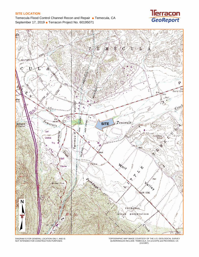
SITE LOCATION
Temecula Flood Control Channel Recon and Repair Temecula, CA
September 17, 2019 Terracon Project No. 60195071
TOPOGRAPHIC MAP IMAGE COURTESY OF THE U.S. GEOLOGICAL SURVEY
QUADRANGLES INCLUDE: TEMECULA, CA (1/1/1975) and PECHANGA, CA (1/1/1997).
DIAGRAM IS FOR GENERAL LOCATION ONLY, AND IS NOT INTENDED FOR CONSTRUCTION PURPOSES
SITE
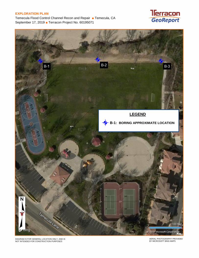
EXPLORATION PLAN
Temecula Flood Control Channel Recon and Repair Temecula, CA
September 17, 2019 Terracon Project No. 60195071
DIAGRAM IS FOR GENERAL LOCATION ONLY, AND IS
NOT INTENDED FOR CONSTRUCTION PURPOSES AERIAL PHOTOGRAPHY PROVIDED BY MICROSOFT BING MAPS
LEGEND
B-1: BORING APPROXIMATE LOCATION

Responsive Resourceful Reliable
EXPLORATION RESULTS
11-11-13
3-4-6
4-5-5N=10
17-23-33
10-10-50/5"
44-45-50/5"
15-17-33N=50
2
25
5
30
68
4
2
2
12
101
94
110
119
NP
43-23-20
POORLY GRADED SAND (SP), trace silt, brown,medium dense
loose
SILTY SAND (SM), trace clay, brown, mediumdense
POORLY GRADED SAND (SP), brown, mediumdense
very dense
SILTY SAND (SM), trace gravel, brown, verydense
SANDY LEAN CLAY (CL), trace gravel, darkbrown, hard
10.0
15.0
25.0
30.0
35.0
1005+/-
1000+/-
990+/-
985+/-
980+/-
Hammer Type: AutomaticStratification lines are approximate. In-situ, the transition may be gradual.
TH
IS B
OR
ING
LO
G IS
NO
T V
ALI
D IF
SE
PA
RA
TE
D F
RO
M O
RIG
INA
L R
EP
OR
T.
GE
O S
MA
RT
LO
G-N
O W
ELL
601
950
71 T
EM
EC
ULA
FL
OO
D C
O.G
PJ
TE
RR
AC
ON
_DA
TA
TE
MP
LAT
E.G
DT
9/1
2/1
9
WA
TE
R L
EV
EL
OB
SE
RV
AT
ION
S
DE
PT
H (
Ft.)
5
10
15
20
25
30
35
STRENGTH TEST
FIE
LD T
ES
TR
ES
ULT
S
CO
MP
RE
SS
IVE
ST
RE
NG
TH
(tsf
)
TE
ST
TY
PE
ST
RA
IN (
%)
PE
RC
EN
T F
INE
S
WA
TE
RC
ON
TE
NT
(%
)
DR
Y U
NIT
WE
IGH
T (
pcf)
ATTERBERGLIMITS
LL-PL-PI
LOCATION See Exploration Plan
Latitude: 33.4725° Longitude: -117.118°
GR
AP
HIC
LO
G
DEPTH ELEVATION (Ft.)
Approximate Surface Elev.: 1015 (Ft.) +/-
Page 1 of 3
Advancement Method:Hollow Stem Auger
Abandonment Method:Boring backfilled with auger cuttings upon completion.
Notes:
Project No.: 60195071
Drill Rig: CME 75
BORING LOG NO. B-1CWE CorpCLIENT:Fullerton, CA
Driller: 2R Drilling
Boring Completed: 08-16-2019
PROJECT: Temecula Flood Control Channel Recon andRepair
See Exploration and Testing Procedures for adescription of field and laboratory proceduresused and additional data (If any).
See Supporting Information for explanation ofsymbols and abbreviations.
Pala Park at 44900 Temecula Ln. Temecula, CASITE:
Boring Started: 08-16-2019
1421 Edinger Ave, Ste CTustin, CA
groundwater encountered
WATER LEVEL OBSERVATIONS
SA
MP
LE T
YP
E

37-41-50/5"
33-50/3"
50/4"
14-35-50/3"
50/4"
19-50/5"
43-50/3"
71
31
7
42
19
11
16
109
121
114
40-26-14SILT WITH SAND (ML), brown, hard
SILTY SAND (SM), trace gravel, brown, verydense
POORLY GRADED SAND WITH SILT ANDGRAVEL (SP-SM), brown, very dense
SILTY SAND (SM), dark brown, very dense
SILTY SAND WITH GRAVEL (SM), brown, verydense
POORLY GRADED GRAVEL WITH SILT ANDSAND (GP-GM), brown, very dense
40.0
45.0
50.0
55.0
65.0
975+/-
970+/-
965+/-
960+/-
950+/-
Hammer Type: AutomaticStratification lines are approximate. In-situ, the transition may be gradual.
TH
IS B
OR
ING
LO
G IS
NO
T V
ALI
D IF
SE
PA
RA
TE
D F
RO
M O
RIG
INA
L R
EP
OR
T.
GE
O S
MA
RT
LO
G-N
O W
ELL
601
950
71 T
EM
EC
ULA
FL
OO
D C
O.G
PJ
TE
RR
AC
ON
_DA
TA
TE
MP
LAT
E.G
DT
9/1
2/1
9
WA
TE
R L
EV
EL
OB
SE
RV
AT
ION
S
DE
PT
H (
Ft.)
40
45
50
55
60
65
70
STRENGTH TEST
FIE
LD T
ES
TR
ES
ULT
S
CO
MP
RE
SS
IVE
ST
RE
NG
TH
(tsf
)
TE
ST
TY
PE
ST
RA
IN (
%)
PE
RC
EN
T F
INE
S
WA
TE
RC
ON
TE
NT
(%
)
DR
Y U
NIT
WE
IGH
T (
pcf)
ATTERBERGLIMITS
LL-PL-PI
LOCATION See Exploration Plan
Latitude: 33.4725° Longitude: -117.118°
GR
AP
HIC
LO
G
DEPTH ELEVATION (Ft.)
Approximate Surface Elev.: 1015 (Ft.) +/-
Page 2 of 3
Advancement Method:Hollow Stem Auger
Abandonment Method:Boring backfilled with auger cuttings upon completion.
Notes:
Project No.: 60195071
Drill Rig: CME 75
BORING LOG NO. B-1CWE CorpCLIENT:Fullerton, CA
Driller: 2R Drilling
Boring Completed: 08-16-2019
PROJECT: Temecula Flood Control Channel Recon andRepair
See Exploration and Testing Procedures for adescription of field and laboratory proceduresused and additional data (If any).
See Supporting Information for explanation ofsymbols and abbreviations.
Pala Park at 44900 Temecula Ln. Temecula, CASITE:
Boring Started: 08-16-2019
1421 Edinger Ave, Ste CTustin, CA
groundwater encountered
WATER LEVEL OBSERVATIONS
SA
MP
LE T
YP
E

23-50/3"
33-50/3"
12-39-50/3"
20-50/4"
23-50/5"
30-50/3"
17-50/6"
POORLY GRADED GRAVEL WITH SILT ANDSAND (GP-GM), brown, very dense (continued)
SILTY SAND (SM), brown, very dense
SILTY SAND WITH GRAVEL (SM), brown, verydense
Boring Terminated at 101 Feet
80.0
90.0
101.0
935+/-
925+/-
914+/-
Hammer Type: AutomaticStratification lines are approximate. In-situ, the transition may be gradual.
TH
IS B
OR
ING
LO
G IS
NO
T V
ALI
D IF
SE
PA
RA
TE
D F
RO
M O
RIG
INA
L R
EP
OR
T.
GE
O S
MA
RT
LO
G-N
O W
ELL
601
950
71 T
EM
EC
ULA
FL
OO
D C
O.G
PJ
TE
RR
AC
ON
_DA
TA
TE
MP
LAT
E.G
DT
9/1
2/1
9
WA
TE
R L
EV
EL
OB
SE
RV
AT
ION
S
DE
PT
H (
Ft.)
75
80
85
90
95
100
STRENGTH TEST
FIE
LD T
ES
TR
ES
ULT
S
CO
MP
RE
SS
IVE
ST
RE
NG
TH
(tsf
)
TE
ST
TY
PE
ST
RA
IN (
%)
PE
RC
EN
T F
INE
S
WA
TE
RC
ON
TE
NT
(%
)
DR
Y U
NIT
WE
IGH
T (
pcf)
ATTERBERGLIMITS
LL-PL-PI
LOCATION See Exploration Plan
Latitude: 33.4725° Longitude: -117.118°
GR
AP
HIC
LO
G
DEPTH ELEVATION (Ft.)
Approximate Surface Elev.: 1015 (Ft.) +/-
Page 3 of 3
Advancement Method:Hollow Stem Auger
Abandonment Method:Boring backfilled with auger cuttings upon completion.
Notes:
Project No.: 60195071
Drill Rig: CME 75
BORING LOG NO. B-1CWE CorpCLIENT:Fullerton, CA
Driller: 2R Drilling
Boring Completed: 08-16-2019
PROJECT: Temecula Flood Control Channel Recon andRepair
See Exploration and Testing Procedures for adescription of field and laboratory proceduresused and additional data (If any).
See Supporting Information for explanation ofsymbols and abbreviations.
Pala Park at 44900 Temecula Ln. Temecula, CASITE:
Boring Started: 08-16-2019
1421 Edinger Ave, Ste CTustin, CA
groundwater encountered
WATER LEVEL OBSERVATIONS
SA
MP
LE T
YP
E
17-24-30
6-8-11N=19
10-14-15
11-13-19N=32
21-30-45
6-16-26N=42
19-53/6"
4
6
23
9
9
10
13
103
102
123
109
POORLY GRADED SAND (SP), trace silt, brown,medium dense
POORLY GRADED SAND WITH SILT (SP-SM),trace gravel, medium dense
dense
SILTY SAND (SM), trace gravel, browndense
very dense
10.0
25.0
1005+/-
990+/-
Hammer Type: AutomaticStratification lines are approximate. In-situ, the transition may be gradual.
TH
IS B
OR
ING
LO
G IS
NO
T V
ALI
D IF
SE
PA
RA
TE
D F
RO
M O
RIG
INA
L R
EP
OR
T.
GE
O S
MA
RT
LO
G-N
O W
ELL
601
950
71 T
EM
EC
ULA
FL
OO
D C
O.G
PJ
TE
RR
AC
ON
_DA
TA
TE
MP
LAT
E.G
DT
9/1
2/1
9
WA
TE
R L
EV
EL
OB
SE
RV
AT
ION
S
DE
PT
H (
Ft.)
5
10
15
20
25
30
35
STRENGTH TEST
FIE
LD T
ES
TR
ES
ULT
S
CO
MP
RE
SS
IVE
ST
RE
NG
TH
(tsf
)
TE
ST
TY
PE
ST
RA
IN (
%)
PE
RC
EN
T F
INE
S
WA
TE
RC
ON
TE
NT
(%
)
DR
Y U
NIT
WE
IGH
T (
pcf)
ATTERBERGLIMITS
LL-PL-PI
LOCATION See Exploration Plan
Latitude: 33.4725° Longitude: -117.1174°
GR
AP
HIC
LO
G
DEPTH ELEVATION (Ft.)
Approximate Surface Elev.: 1015 (Ft.) +/-
Page 1 of 3
Advancement Method:Hollow Stem Auger
Abandonment Method:Boring backfilled with auger cuttings upon completion.
Notes:
Project No.: 60195071
Drill Rig: CME 75
BORING LOG NO. B-2CWE CorpCLIENT:Fullerton, CA
Driller: 2R Drilling
Boring Completed: 08-14-2019
PROJECT: Temecula Flood Control Channel Recon andRepair
See Exploration and Testing Procedures for adescription of field and laboratory proceduresused and additional data (If any).
See Supporting Information for explanation ofsymbols and abbreviations.
Pala Park at 44900 Temecula Ln. Temecula, CASITE:
Boring Started: 08-14-2019
1421 Edinger Ave, Ste CTustin, CA
groundwater encountered
WATER LEVEL OBSERVATIONS
SA
MP
LE T
YP
E
11-22-29N=51
5-27-50/3"
26-50/6"
50/3"
52/6"
50/6"
33-50/6"
27
4
16
12
25
113
113
100
33-28-5SILTY SAND (SM), trace gravel, brown (continued)
POORLY GRADED SAND WITH GRAVEL (SP),trace silt, brown, very denseencountered shale layer
POORLY GRADED GRAVEL W/SAND (GP),brown, very dense
40.0
50.0
70.0
975+/-
965+/-
945+/-
Hammer Type: AutomaticStratification lines are approximate. In-situ, the transition may be gradual.
TH
IS B
OR
ING
LO
G IS
NO
T V
ALI
D IF
SE
PA
RA
TE
D F
RO
M O
RIG
INA
L R
EP
OR
T.
GE
O S
MA
RT
LO
G-N
O W
ELL
601
950
71 T
EM
EC
ULA
FL
OO
D C
O.G
PJ
TE
RR
AC
ON
_DA
TA
TE
MP
LAT
E.G
DT
9/1
2/1
9
WA
TE
R L
EV
EL
OB
SE
RV
AT
ION
S
DE
PT
H (
Ft.)
40
45
50
55
60
65
70
STRENGTH TEST
FIE
LD T
ES
TR
ES
ULT
S
CO
MP
RE
SS
IVE
ST
RE
NG
TH
(tsf
)
TE
ST
TY
PE
ST
RA
IN (
%)
PE
RC
EN
T F
INE
S
WA
TE
RC
ON
TE
NT
(%
)
DR
Y U
NIT
WE
IGH
T (
pcf)
ATTERBERGLIMITS
LL-PL-PI
LOCATION See Exploration Plan
Latitude: 33.4725° Longitude: -117.1174°
GR
AP
HIC
LO
G
DEPTH ELEVATION (Ft.)
Approximate Surface Elev.: 1015 (Ft.) +/-
Page 2 of 3
Advancement Method:Hollow Stem Auger
Abandonment Method:Boring backfilled with auger cuttings upon completion.
Notes:
Project No.: 60195071
Drill Rig: CME 75
BORING LOG NO. B-2CWE CorpCLIENT:Fullerton, CA
Driller: 2R Drilling
Boring Completed: 08-14-2019
PROJECT: Temecula Flood Control Channel Recon andRepair
See Exploration and Testing Procedures for adescription of field and laboratory proceduresused and additional data (If any).
See Supporting Information for explanation ofsymbols and abbreviations.
Pala Park at 44900 Temecula Ln. Temecula, CASITE:
Boring Started: 08-14-2019
1421 Edinger Ave, Ste CTustin, CA
groundwater encountered
WATER LEVEL OBSERVATIONS
SA
MP
LE T
YP
E
7-34-50/3"
30-39-50/5"
10-22-50/5"
31-50/6"
29-50/4"
13-32-50/4"
26-45-50N=95
POORLY GRADED SAND WITH GRAVEL (SP),trace silt, brown, very dense
SILT WITH SAND (ML), brown, hard
POORLY GRADED GRAVEL W/SAND (GP),brown, very dense
SILT WITH SAND (ML), brown, hard
Boring Terminated at 101.5 Feet
80.0
85.0
95.0
101.5
935+/-
930+/-
920+/-
913.5+/-
Hammer Type: AutomaticStratification lines are approximate. In-situ, the transition may be gradual.
TH
IS B
OR
ING
LO
G IS
NO
T V
ALI
D IF
SE
PA
RA
TE
D F
RO
M O
RIG
INA
L R
EP
OR
T.
GE
O S
MA
RT
LO
G-N
O W
ELL
601
950
71 T
EM
EC
ULA
FL
OO
D C
O.G
PJ
TE
RR
AC
ON
_DA
TA
TE
MP
LAT
E.G
DT
9/1
2/1
9
WA
TE
R L
EV
EL
OB
SE
RV
AT
ION
S
DE
PT
H (
Ft.)
75
80
85
90
95
100
STRENGTH TEST
FIE
LD T
ES
TR
ES
ULT
S
CO
MP
RE
SS
IVE
ST
RE
NG
TH
(tsf
)
TE
ST
TY
PE
ST
RA
IN (
%)
PE
RC
EN
T F
INE
S
WA
TE
RC
ON
TE
NT
(%
)
DR
Y U
NIT
WE
IGH
T (
pcf)
ATTERBERGLIMITS
LL-PL-PI
LOCATION See Exploration Plan
Latitude: 33.4725° Longitude: -117.1174°
GR
AP
HIC
LO
G
DEPTH ELEVATION (Ft.)
Approximate Surface Elev.: 1015 (Ft.) +/-
Page 3 of 3
Advancement Method:Hollow Stem Auger
Abandonment Method:Boring backfilled with auger cuttings upon completion.
Notes:
Project No.: 60195071
Drill Rig: CME 75
BORING LOG NO. B-2CWE CorpCLIENT:Fullerton, CA
Driller: 2R Drilling
Boring Completed: 08-14-2019
PROJECT: Temecula Flood Control Channel Recon andRepair
See Exploration and Testing Procedures for adescription of field and laboratory proceduresused and additional data (If any).
See Supporting Information for explanation ofsymbols and abbreviations.
Pala Park at 44900 Temecula Ln. Temecula, CASITE:
Boring Started: 08-14-2019
1421 Edinger Ave, Ste CTustin, CA
groundwater encountered
WATER LEVEL OBSERVATIONS
SA
MP
LE T
YP
E

7-13-19
10-15-19
5-5-6N=11
14-17-19
9-13-14N=27
12-12-10
8-20-29N=49
37
5
2
3
4
16
105
99
107
95
33-25-8
SILTY SAND (SM), trace gravel, brown, mediumdense
POORLY GRADED SAND (SP), brown, mediumdense
SILTY SAND (SM), brown, medium dense
trace gravel, dense
15.0
25.0
35.0
1000+/-
990+/-
980+/-
Hammer Type: AutomaticStratification lines are approximate. In-situ, the transition may be gradual.
TH
IS B
OR
ING
LO
G IS
NO
T V
ALI
D IF
SE
PA
RA
TE
D F
RO
M O
RIG
INA
L R
EP
OR
T.
GE
O S
MA
RT
LO
G-N
O W
ELL
601
950
71 T
EM
EC
ULA
FL
OO
D C
O.G
PJ
TE
RR
AC
ON
_DA
TA
TE
MP
LAT
E.G
DT
9/1
2/1
9
WA
TE
R L
EV
EL
OB
SE
RV
AT
ION
S
DE
PT
H (
Ft.)
5
10
15
20
25
30
35
STRENGTH TEST
FIE
LD T
ES
TR
ES
ULT
S
CO
MP
RE
SS
IVE
ST
RE
NG
TH
(tsf
)
TE
ST
TY
PE
ST
RA
IN (
%)
PE
RC
EN
T F
INE
S
WA
TE
RC
ON
TE
NT
(%
)
DR
Y U
NIT
WE
IGH
T (
pcf)
ATTERBERGLIMITS
LL-PL-PI
LOCATION See Exploration Plan
Latitude: 33.4725° Longitude: -117.1168°
GR
AP
HIC
LO
G
DEPTH ELEVATION (Ft.)
Approximate Surface Elev.: 1015 (Ft.) +/-
Page 1 of 3
Advancement Method:Hollow Stem Auger
Abandonment Method:Boring backfilled with auger cuttings upon completion.
Notes:
Project No.: 60195071
Drill Rig: CME 75
BORING LOG NO. B-3CWE CorpCLIENT:Fullerton, CA
Driller: 2R Drilling
Boring Completed: 08-15-2019
PROJECT: Temecula Flood Control Channel Recon andRepair
See Exploration and Testing Procedures for adescription of field and laboratory proceduresused and additional data (If any).
See Supporting Information for explanation ofsymbols and abbreviations.
Pala Park at 44900 Temecula Ln. Temecula, CASITE:
Boring Started: 08-15-2019
1421 Edinger Ave, Ste CTustin, CA
groundwater encountered
WATER LEVEL OBSERVATIONS
SA
MP
LE T
YP
E
7-11-50/5"
8-25-28N=53
14-44-50/3"
16-33-42N=75
50/6"
7-50/6"
26-50/5"
73
31
12
9
9
115
127
114
SILT WITH SAND (ML), trace gravel, brown, hard
SILTY SAND (SM), trace gravel, brown, verydense
40.0
70.0
975+/-
945+/-
Hammer Type: AutomaticStratification lines are approximate. In-situ, the transition may be gradual.
TH
IS B
OR
ING
LO
G IS
NO
T V
ALI
D IF
SE
PA
RA
TE
D F
RO
M O
RIG
INA
L R
EP
OR
T.
GE
O S
MA
RT
LO
G-N
O W
ELL
601
950
71 T
EM
EC
ULA
FL
OO
D C
O.G
PJ
TE
RR
AC
ON
_DA
TA
TE
MP
LAT
E.G
DT
9/1
2/1
9
WA
TE
R L
EV
EL
OB
SE
RV
AT
ION
S
DE
PT
H (
Ft.)
40
45
50
55
60
65
70
STRENGTH TEST
FIE
LD T
ES
TR
ES
ULT
S
CO
MP
RE
SS
IVE
ST
RE
NG
TH
(tsf
)
TE
ST
TY
PE
ST
RA
IN (
%)
PE
RC
EN
T F
INE
S
WA
TE
RC
ON
TE
NT
(%
)
DR
Y U
NIT
WE
IGH
T (
pcf)
ATTERBERGLIMITS
LL-PL-PI
LOCATION See Exploration Plan
Latitude: 33.4725° Longitude: -117.1168°
GR
AP
HIC
LO
G
DEPTH ELEVATION (Ft.)
Approximate Surface Elev.: 1015 (Ft.) +/-
Page 2 of 3
Advancement Method:Hollow Stem Auger
Abandonment Method:Boring backfilled with auger cuttings upon completion.
Notes:
Project No.: 60195071
Drill Rig: CME 75
BORING LOG NO. B-3CWE CorpCLIENT:Fullerton, CA
Driller: 2R Drilling
Boring Completed: 08-15-2019
PROJECT: Temecula Flood Control Channel Recon andRepair
See Exploration and Testing Procedures for adescription of field and laboratory proceduresused and additional data (If any).
See Supporting Information for explanation ofsymbols and abbreviations.
Pala Park at 44900 Temecula Ln. Temecula, CASITE:
Boring Started: 08-15-2019
1421 Edinger Ave, Ste CTustin, CA
groundwater encountered
WATER LEVEL OBSERVATIONS
SA
MP
LE T
YP
E

20-28-50/3"
6-26-50/3"
44-50/3"
8-30-50/3"
10-25-26N=51
18-37-50/3"
14-17-28N=45
POORLY GRADED GRAVEL WITH SILT ANDSAND (GP-GM), brown, very dense
POORLY GRADED SAND WITH SILT (SP-SM),brown, very dense
POORLY GRADED GRAVEL WITH SILT ANDSAND (GP-GM), brown, very dense
SILTY SAND WITH GRAVEL (SM), brown, verydense
dark brown with black
dense
Boring Terminated at 101.5 Feet
75.0
80.0
90.0
101.5
940+/-
935+/-
925+/-
913.5+/-
Hammer Type: AutomaticStratification lines are approximate. In-situ, the transition may be gradual.
TH
IS B
OR
ING
LO
G IS
NO
T V
ALI
D IF
SE
PA
RA
TE
D F
RO
M O
RIG
INA
L R
EP
OR
T.
GE
O S
MA
RT
LO
G-N
O W
ELL
601
950
71 T
EM
EC
ULA
FL
OO
D C
O.G
PJ
TE
RR
AC
ON
_DA
TA
TE
MP
LAT
E.G
DT
9/1
2/1
9
WA
TE
R L
EV
EL
OB
SE
RV
AT
ION
S
DE
PT
H (
Ft.)
75
80
85
90
95
100
STRENGTH TEST
FIE
LD T
ES
TR
ES
ULT
S
CO
MP
RE
SS
IVE
ST
RE
NG
TH
(tsf
)
TE
ST
TY
PE
ST
RA
IN (
%)
PE
RC
EN
T F
INE
S
WA
TE
RC
ON
TE
NT
(%
)
DR
Y U
NIT
WE
IGH
T (
pcf)
ATTERBERGLIMITS
LL-PL-PI
LOCATION See Exploration Plan
Latitude: 33.4725° Longitude: -117.1168°
GR
AP
HIC
LO
G
DEPTH ELEVATION (Ft.)
Approximate Surface Elev.: 1015 (Ft.) +/-
Page 3 of 3
Advancement Method:Hollow Stem Auger
Abandonment Method:Boring backfilled with auger cuttings upon completion.
Notes:
Project No.: 60195071
Drill Rig: CME 75
BORING LOG NO. B-3CWE CorpCLIENT:Fullerton, CA
Driller: 2R Drilling
Boring Completed: 08-15-2019
PROJECT: Temecula Flood Control Channel Recon andRepair
See Exploration and Testing Procedures for adescription of field and laboratory proceduresused and additional data (If any).
See Supporting Information for explanation ofsymbols and abbreviations.
Pala Park at 44900 Temecula Ln. Temecula, CASITE:
Boring Started: 08-15-2019
1421 Edinger Ave, Ste CTustin, CA
groundwater encountered
WATER LEVEL OBSERVATIONS
SA
MP
LE T
YP
E

0
10
20
30
40
50
60
0 20 40 60 80 100
CH o
r
OH
CL o
r
OL
ML or OL
MH or OH
"U" L
ine
"A" L
ine
ATTERBERG LIMITS RESULTSASTM D4318
PLASTICITY
INDEX
LIQUID LIMIT
PROJECT NUMBER: 60195071
SITE: Pala Park at 44900 Temecula Ln. Temecula, CA
PROJECT: Temecula Flood Control ChannelRecon and Repair
CLIENT: CWE Corp Fullerton, CA
1421 Edinger Ave, Ste CTustin, CA
LAB
OR
AT
OR
Y T
ES
TS
AR
E N
OT
VA
LID
IF S
EP
AR
AT
ED
FR
OM
OR
IGIN
AL
RE
PO
RT
.
AT
TE
RB
ER
G L
IMIT
S 6
0195
071
TE
ME
CU
LA F
LO
OD
CO
.GP
J T
ER
RA
CO
N_D
AT
AT
EM
PLA
TE
.GD
T 9
/12
/19
NP
43
40
33
33
NP
23
26
28
25
NP
20
14
5
8
PIPLLLBoring ID Depth
B-1
B-1
B-1
B-2
B-3
25.1
68.1
70.7
27.4
Fines
10 - 11.5
30 - 31.5
35 - 36.4
35 - 36.5
30 - 31.5
SM
CL
ML
SM
SM
SILTY SAND
SANDY LEAN CLAY
SILT with SAND
SILTY SAND
SILTY SAND
DescriptionUSCS
CL-ML
0
500
1,000
1,500
2,000
2,500
3,000
3,500
4,000
0 500 1,000 1,500 2,000 2,500 3,000 3,500 4,000
2
10
4
16
NORMAL PRESSURE, psf
SH
EA
R S
TR
EN
GT
H,
psf
c, psf
204
450
384
522
34
37
30
27
°
DIRECT SHEAR TESTASTM D3080
94
123
107
95
PROJECT NUMBER: 60195071PROJECT: Temecula Flood Control Channel
Recon and Repair
SITE: Pala Park at 44900 Temecula Ln. Temecula, CA
CLIENT: CWE Corp Fullerton, CA
EXHIBIT: B-1
1421 Edinger Ave, Ste CTustin, CA
, pcf
POORLY GRADED SAND (SP)
POORLY GRADED SAND WITH SILT (SP-SM)
POORLY GRADED SAND WITH SILT (SP-SM)
SILTY SAND (SM)
Specimen Identification Classification
B-1
B-2
B-3
B-3
WC,%
5 - 6.5
20 - 21.5
15 - 16.5
25 - 26.5
LAB
OR
AT
OR
Y T
ES
TS
AR
E N
OT
VA
LID
IF S
EP
AR
AT
ED
FR
OM
OR
IGIN
AL
RE
PO
RT
.
DIR
EC
T_S
HE
AR
601
950
71 T
EM
EC
ULA
FLO
OD
CO
.GP
J T
ER
RA
CO
N_D
AT
AT
EM
PLA
TE
.GD
T 9
/12
/19

0
5
10
15
20
25
30
35
40
45
50
55
60
65
70
75
80
85
90
95
100
0.0010.010.1110100
3/4 1/23/8 30 403 60
HYDROMETERU.S. SIEVE OPENING IN INCHES
16 20
100
90
80
70
60
50
40
30
20
10
0
U.S. SIEVE NUMBERS
44 10063 2 10 14 506 2001.5 81 140
PE
RC
EN
T F
INE
R B
Y W
EIG
HT
PE
RC
EN
T C
OA
RS
ER
BY
WE
IGH
T
GRAIN SIZE DISTRIBUTIONASTM D422 / ASTM C136
PROJECT NUMBER: 60195071
SITE: Pala Park at 44900 Temecula Ln. Temecula, CA
PROJECT: Temecula Flood Control ChannelRecon and Repair
CLIENT: CWE Corp Fullerton, CA
1421 Edinger Ave, Ste CTustin, CA
LAB
OR
AT
OR
Y T
ES
TS
AR
E N
OT
VA
LID
IF S
EP
AR
AT
ED
FR
OM
OR
IGIN
AL
RE
PO
RT
.
GR
AIN
SIZ
E: U
SC
S 1
601
950
71 T
EM
EC
ULA
FL
OO
D C
O.G
PJ
TE
RR
AC
ON
_DA
TA
TE
MP
LAT
E.G
DT
9/1
2/1
9
2.7
9.8
1.8
67.6
59.5
74.8
29.8
30.8
23.4
B-1
B-1
B-2
fine coarse
1.016 0.955 0.876
0.079 0.165
finemediumCOBBLES
GRAVEL SANDSILT OR CLAY
0.0
0.0
0.0
D30
D60
BORING ID
1"3/4"1/2"3/8"#4#8#16#30#40#60#100#200
100.098.298.298.297.3486.6966.9851.6546.440.3333.1829.76
1 1/2"1"
3/4"1/2"3/8"#4#8#16#30#40#60#100#200
100.098.4296.5295.2993.8490.2182.569.2354.9554.845.4837.9130.76
100.099.2198.8298.8298.2394.2279.2158.0548.7239.7128.4123.42
1"3/4"1/2"3/8"#4#8#16#30#40#60#100#200
CC
CU
coarse
D10
25 - 26.4
40 - 40.8
25 - 26.5
Sieve
REMARKS
SOIL DESCRIPTION% Finer% Finer SieveSieve% Finer
USCS% CLAY% FINES% SILT% SAND% GRAVEL% COBBLESDEPTH
COEFFICIENTS
GRAIN SIZE

0
5
10
15
20
25
30
35
40
45
50
55
60
65
70
75
80
85
90
95
100
0.0010.010.1110100
3/4 1/23/8 30 403 60
HYDROMETERU.S. SIEVE OPENING IN INCHES
16 20
100
90
80
70
60
50
40
30
20
10
0
U.S. SIEVE NUMBERS
44 10063 2 10 14 506 2001.5 81 140
PE
RC
EN
T F
INE
R B
Y W
EIG
HT
PE
RC
EN
T C
OA
RS
ER
BY
WE
IGH
T
GRAIN SIZE DISTRIBUTIONASTM D422 / ASTM C136
PROJECT NUMBER: 60195071
SITE: Pala Park at 44900 Temecula Ln. Temecula, CA
PROJECT: Temecula Flood Control ChannelRecon and Repair
CLIENT: CWE Corp Fullerton, CA
1421 Edinger Ave, Ste CTustin, CA
LAB
OR
AT
OR
Y T
ES
TS
AR
E N
OT
VA
LID
IF S
EP
AR
AT
ED
FR
OM
OR
IGIN
AL
RE
PO
RT
.
GR
AIN
SIZ
E: U
SC
S 1
601
950
71 T
EM
EC
ULA
FL
OO
D C
O.G
PJ
TE
RR
AC
ON
_DA
TA
TE
MP
LAT
E.G
DT
9/1
2/1
9
0.4
9.8
26.9
59.0
72.6
31.2
B-3
B-3
fine coarse
1.144
finemediumCOBBLES
GRAVEL SANDSILT OR CLAY
0.0
0.0
D30
D60
BORING ID
1/2"3/8"#4#8#16#30#40#60#100#200
100.099.8299.5597.9396.8596.8596.7293.5384.872.64
1"3/4"1/2"3/8"#4#8#16#30#40#60#100#200
100.097.9796.2395.3590.2276.061.1648.7644.5740.5134.931.2
CC
CU
coarse
D10
35 - 36.4
45 - 46.3
Sieve
REMARKS
SOIL DESCRIPTION% Finer% Finer SieveSieve% Finer
USCS% CLAY% FINES% SILT% SAND% GRAVEL% COBBLESDEPTH
COEFFICIENTS
GRAIN SIZE

Project Number:
Service Date:
Report Date:
Task:
Client
Date Received:
B-1
0.0-2.5
8.77
0.02
Nil
27
+679
238
9409
Analyzed By:
CHEMICAL LABORATORY TEST REPORT
Trisha Campo
pH Analysis, AWWA 4500 H
Water Soluble Sulfate (SO4), AWWA 4500 E
(percent %)
Sulfides, AWWA 4500-S D, (mg/kg)
Chlorides, ASTM D 512, (mg/kg)
Red-Ox, AWWA 2580, (mV)
Total Salts, AWWA 2540, (mg/kg)
Resistivity, ASTM G 57, (ohm-cm)
CWE Corp Temecula Flood Control Channel Recon and Repair at Pala Park
09/03/19
750 Pilot Road, Suite F
Las Vegas, Nevada 89119
(702) 597-9393
Project
Fullerton, CA
Lab No.: 19-0962
Sample Number
Sample Location
Sample Depth (ft.)
The tests were performed in general accordance with applicable ASTM, AASHTO, or DOT test methods. This report is exclusively for the use of the client
indicated above and shall not be reproduced except in full without the written consent of our company. Test results transmitted herein are only applicable to
the actual samples tested at the location(s) referenced and are not necessarily indicative of the properties of other apparently similar or identical materials.
60195071
Terracon (60)Sample Submitted By: 8/26/2019
Results of Corrosion Analysis
Chemist
08/27/19

Responsive Resourceful Reliable
SUPPORTING INFORMATION

UNIFIED SOIL CLASSIFICATION SYSTEM
Responsive Resourceful Reliable
UNIFIED SOIL C LASSIFIC AT ION SYSTEM
Criteria for Assigning Group Symbols and Group Names Using Laboratory Tests A Soil Classification
Group Symbol
Group Name B
Coarse-Grained Soils: More than 50% retained on No. 200 sieve
Gravels: More than 50% of coarse fraction retained on No. 4 sieve
Clean Gravels:
Less than 5% fines C
Cu 4 and 1 Cc 3 E GW Well-graded gravel F
Cu 4 and/or [Cc<1 or Cc>3.0] E GP Poorly graded gravel F
Gravels with Fines:
More than 12% fines C
Fines classify as ML or MH GM Silty gravel F, G, H
Fines classify as CL or CH GC Clayey gravel F, G, H
Sands: 50% or more of coarse fraction passes No. 4 sieve
Clean Sands:
Less than 5% fines D
Cu 6 and 1 Cc 3 E SW Well-graded sand I
Cu 6 and/or [Cc<1 or Cc>3.0] E SP Poorly graded sand I
Sands with Fines:
More than 12% fines D
Fines classify as ML or MH SM Silty sand G, H, I
Fines classify as CL or CH SC Clayey sand G, H, I
Fine-Grained Soils: 50% or more passes the No. 200 sieve
Silts and Clays: Liquid limit less than 50
Inorganic: PI 7 and plots on or above “A” line J
CL Lean clay K, L, M
PI 4 or plots below “A” line J ML Silt K, L, M
Organic: Liquid limit - oven dried
0.75 OL Organic clay K, L, M, N
Liquid limit - not dried Organic silt K, L, M, O
Silts and Clays: Liquid limit 50 or more
Inorganic: PI plots on or above “A” line CH Fat clay K, L, M
PI plots below “A” line MH Elastic Silt K, L, M
Organic: Liquid limit - oven dried
0.75 OH Organic clay K, L, M, P
Liquid limit - not dried Organic silt K, L, M, Q
Highly organic soils: Primarily organic matter, dark in color, and organic odor PT Peat
A Based on the material passing the 3-inch (75-mm) sieve.
B If field sample contained cobbles or boulders, or both, add “with cobbles
or boulders, or both” to group name.
C Gravels with 5 to 12% fines require dual symbols: GW-GM well-graded
gravel with silt, GW-GC well-graded gravel with clay, GP-GM poorly graded gravel with silt, GP-GC poorly graded gravel with clay.
D Sands with 5 to 12% fines require dual symbols: SW-SM well-graded
sand with silt, SW-SC well-graded sand with clay, SP-SM poorly graded sand with silt, SP-SC poorly graded sand with clay.
E Cu = D60/D10 Cc =
6010
2
30
DxD
)(D
F If soil contains 15% sand, add “with sand” to group name.
G If fines classify as CL-ML, use dual symbol GC-GM, or SC-SM.
H If fines are organic, add “with organic fines” to group name.
I If soil contains 15% gravel, add “with gravel” to group name.
J If Atterberg limits plot in shaded area, soil is a CL-ML, silty clay.
K If soil contains 15 to 29% plus No. 200, add “with sand” or “with
gravel,” whichever is predominant.
L If soil contains 30% plus No. 200 predominantly sand, add
“sandy” to group name.
M If soil contains 30% plus No. 200, predominantly gravel, add
“gravelly” to group name.
N PI 4 and plots on or above “A” line.
O PI 4 or plots below “A” line.
P PI plots on or above “A” line.
Q PI plots below “A” line.

less than 0.25
0.50 to 1.00
> 4.00
UnconfinedCompressive Strength
Qu, (tsf)
0.25 to 0.50
1.00 to 2.00
2.00 to 4.00
AugerCuttings
ModifiedDames &Moore RingSampler
StandardPenetrationTest
Trace
PLASTICITY DESCRIPTION
Water levels indicated on the soil boring logs arethe levels measured in the borehole at the timesindicated. Groundwater level variations will occurover time. In low permeability soils, accuratedetermination of groundwater levels is notpossible with short term water levelobservations.
DESCRIPTION OF SYMBOLS AND ABBREVIATIONSGENERAL NOTES
> 30
11 - 30
1 - 10Low
Non-plastic
Plasticity Index
#4 to #200 sieve (4.75mm to 0.075mm
Boulders
12 in. to 3 in. (300mm to 75mm)Cobbles
3 in. to #4 sieve (75mm to 4.75 mm)Gravel
Sand
Passing #200 sieve (0.075mm)Silt or Clay
Particle Size
Water Level Aftera Specified Period of Time
Water Level After aSpecified Period of Time
Water InitiallyEncountered
Soil classification is based on the Unified Soil Classification System. Coarse Grained Soils have more than 50% of theirdry weight retained on a #200 sieve; their principal descriptors are: boulders, cobbles, gravel or sand. Fine Grained Soilshave less than 50% of their dry weight retained on a #200 sieve; they are principally described as clays if they are plastic,and silts if they are slightly plastic or non-plastic. Major constituents may be added as modifiers and minor constituentsmay be added according to the relative proportions based on grain size. In addition to gradation, coarse-grained soils aredefined on the basis of their in-place relative density and fine-grained soils on the basis of their consistency.
GRAIN SIZE TERMINOLOGY
RELATIVE PROPORTIONS OF FINESRELATIVE PROPORTIONS OF SAND AND GRAVEL
DESCRIPTIVE SOIL CLASSIFICATION
LOCATION AND ELEVATION NOTES
SAMPLING WATER LEVEL FIELD TESTSN
(HP)
(T)
(DCP)
UC
(PID)
(OVA)
Standard Penetration TestResistance (Blows/Ft.)
Hand Penetrometer
Torvane
Dynamic Cone Penetrometer
Unconfined CompressiveStrength
Photo-Ionization Detector
Organic Vapor Analyzer
Medium
0Over 12 in. (300 mm)
>12
5-12
<5
Percent ofDry Weight
TermMajor Component of Sample
Modifier
With
Trace
Descriptive Term(s) ofother constituents
>30Modifier
<15
Percent ofDry Weight
Descriptive Term(s) ofother constituents
With 15-29
High
Unless otherwise noted, Latitude and Longitude are approximately determined using a hand-held GPS device. Theaccuracy of such devices is variable. Surface elevation data annotated with +/- indicates that no actual topographicalsurvey was conducted to confirm the surface elevation. Instead, the surface elevation was approximately determined fromtopographic maps of the area.
Descriptive Term(Consistency)
0 - 6
CONSISTENCY OF FINE-GRAINED SOILS
Hard
Very Loose
Loose
Medium Dense
Dense
Very Dense
Descriptive Term(Density)
Standard Penetrationor N-ValueBlows/Ft.
0 - 3
4 - 9 7 - 18
10 - 29 19 - 58
30 - 50 59 - 98
> 50 > 99 Very Stiff
Standard Penetration orN-Value
Blows/Ft.
Ring SamplerBlows/Ft.
Ring SamplerBlows/Ft.
5 - 9
Stiff
Medium Stiff
Soft
Very Soft
(50% or more passing the No. 200 sieve.)Consistency determined by laboratory shear strength testing, field visual-manual
procedures or standard penetration resistance
STRENGTH TERMS
RELATIVE DENSITY OF COARSE-GRAINED SOILS
(More than 50% retained on No. 200 sieve.)Density determined by Standard Penetration Resistance
2 - 4
4 - 8
8 - 15
15 - 30
> 30
0 - 1
3 - 4
< 3
10 - 18
19 - 42
> 42