Embed Size (px)
Citation preview
GEOTECHNICAL ENGINEERING STUDY
FOR
UNIVERSITY VILLAGE AVERY CENTRE APARTMENTS SW INTERSECTION OF SATELLITE VIEW AND COLLEGE PARK DRIVE
ROUND ROCK, TEXAS
GEOTECHNICAL ENGINEERING STUDY
For
UNIVERSITY VILLAGE AVERY CENTRE APARTMENTS SOUTHWEST INTERSECTION OF SATELLITE VIEW AND COLLEGE PARK DRIVE
ROUND ROCK, TEXAS
Prepared for
MN CAPITAL STRATEGIES OR ASSIGNS Birmingham, Alabama
Prepared by
RABA KISTNER CONSULTANTS, INC. Austin, Texas
PROJECT NO. AAA16‐089‐00
November 16, 2016
Project No. AAA16‐089‐00 November 16, 2016
TABLE OF CONTENTS
i
INTRODUCTION .......................................................................................................................................... 1
PROJECT DESCRIPTION ............................................................................................................................... 1
LIMITATIONS .............................................................................................................................................. 2
BORINGS AND LABORATORY TESTS ........................................................................................................... 2
MOISTURE DENSITY RELATIONSHIP ............................................................................................................. 3
GENERAL SITE CONDITIONS ....................................................................................................................... 4
SITE DESCRIPTION ......................................................................................................................................... 4
GEOLOGY ....................................................................................................................................................... 4
SEISMIC CONSIDERATIONS ........................................................................................................................... 4
STRATIGRAPHY .............................................................................................................................................. 5
GROUNDWATER ............................................................................................................................................ 5
FOUNDATION ANALYSIS ............................................................................................................................. 5
EXPANSIVE SOIL‐RELATED MOVEMENTS ..................................................................................................... 5
OPTIONS FOR REDUCING EXPANSIVE SOIL‐RELATED MOVEMENTS ........................................................... 6 Option 1: Overexcavation and Select Fill Replacement ........................................................................ 6 Option 2: Combination of Alternate Select Fill Replacement and Moisture Conditioning .................. 6
DRAINAGE CONSIDERATIONS ....................................................................................................................... 7
FOUNDATION RECOMMENDATIONS .......................................................................................................... 8
SITE GRADING ................................................................................................................................................ 8
ENGINEERED BEAM AND SLAB FOUNDATION ............................................................................................. 8 Allowable Bearing Capacity .................................................................................................................... 8 PTI Design Parameters ........................................................................................................................... 9
AREA FLATWORK ......................................................................................................................................... 10
FOUNDATION CONSTRUCTION CONSIDERATIONS ................................................................................... 11
SITE DRAINAGE ............................................................................................................................................ 11
SITE PREPARATION ...................................................................................................................................... 11
MOISTURE CONDITIONING ......................................................................................................................... 12
PERIMETER MOISTURE BARRIER ................................................................................................................ 12
SELECT FILL .................................................................................................................................................. 12
ALTERNATE SELECT FILL .............................................................................................................................. 13
SHALLOW FOUNDATION EXCAVATIONS .................................................................................................... 13
EXCAVATION SLOPING AND BENCHING ..................................................................................................... 13
EXCAVATION EQUIPMENT .......................................................................................................................... 14
UTILITIES ...................................................................................................................................................... 14
Project No. AAA16‐089‐00 November 16, 2016
TABLE OF CONTENTS
ii
PAVEMENT RECOMMENDATIONS ............................................................................................................ 14
SUBGRADE CONDITIONS ............................................................................................................................. 15
DESIGN INFORMATION ............................................................................................................................... 15
FLEXIBLE PAVEMENT ................................................................................................................................... 15 Garbage Dumpsters .............................................................................................................................. 16
RIGID PAVEMENT ........................................................................................................................................ 16
PAVEMENT CONSTRUCTION CONSIDERATIONS ....................................................................................... 17
SUBGRADE PREPARATION .......................................................................................................................... 17
DRAINAGE CONSIDERATIONS ..................................................................................................................... 17
ON‐SITE CLAY FILL ........................................................................................................................................ 17
LIME TREATMENT OF SUBGRADE ............................................................................................................... 18
GEOGRID REINFORCEMENT ........................................................................................................................ 18
FLEXIBLE BASE COURSE ............................................................................................................................... 19
ASPHALTIC CONCRETE SURFACE COURSE .................................................................................................. 19
PORTLAND CEMENT CONCRETE ................................................................................................................. 19
CONSTRUCTION RELATED SERVICES ......................................................................................................... 19
CONSTRUCTION MATERIALS TESTING AND OBSERVATION SERVICES ...................................................... 19
BUDGETING FOR CONSTRUCTION TESTING ............................................................................................... 20
ATTACHMENTS
The following figures are attached and complete this report: Boring Location Map .......................................................................................................................... Figure 1 Logs of Borings ........................................................................................................................ Figures 2 to 11 Key to Terms and Symbols ............................................................................................................... Figure 12 Results of Soil Analyses .................................................................................................................... Figure 13 Grain Size Curve ............................................................................................................................... Figure 14 Moisture Density Relationship Curve .............................................................................................. Figure 15 Important Information About Your Geotechnical Engineering Report
Project No. AAA16‐089‐00 November 16, 2016
1
INTRODUCTION RABA KISTNER Consultants Inc. (RKCI) has completed the authorized subsurface exploration and foundation analysis for the University Village Avery Centre apartments to be located on College Park Drive, southwest of its intersection with Satellite View in Round, Rock. This report briefly describes the procedures utilized during this study and presents our findings along with our recommendations for foundation design and construction considerations, as well as for pavement design and construction guidelines for the apartment complex community.
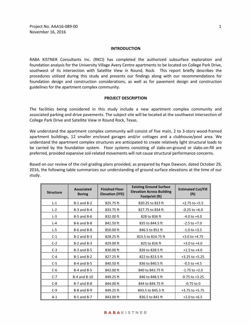
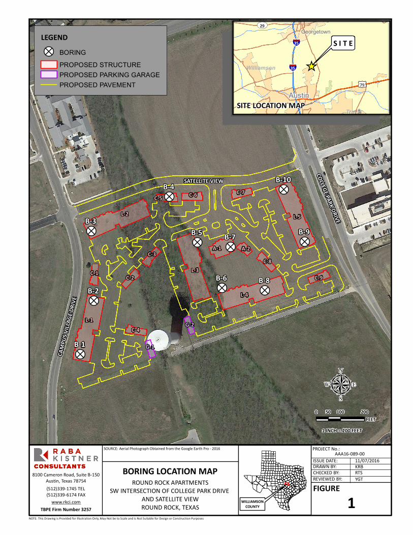
PROJECT DESCRIPTION The facilities being considered in this study include a new apartment complex community and associated parking and drive pavements. The subject site will be located at the southwest intersection of College Park Drive and Satellite View in Round Rock, Texas. We understand the apartment complex community will consist of five main, 2 to 3‐story wood‐framed apartment buildings, 12 smaller enclosed garages and/or cottages and a clubhouse/pool area. We understand the apartment complex structures are anticipated to create relatively light structural loads to be carried by the foundation system. Floor systems consisting of slabs‐on‐ground or slabs‐on‐fill are preferred, provided expansive soil‐related movements will not cause structural performance concerns. Based on our review of the civil grading plans provided, as prepared by Pape Dawson, dated October 29, 2016, the following table summarizes our understanding of ground surface elevations at the time of our study.
Structure Associated Boring
Finished Floor Elevation (FFE)
Existing Ground Surface Elevation Across Building
Footprint (ft)
Estimated Cut/Fill (ft)
L‐1 B‐1 and B‐2 825.75 ft 820.25 to 823 ft +2.75 to +5.5
L‐2 B‐3 and B‐4 833.75 ft 827.75 to 834 ft ‐0.25 to +6.0
L‐3 B‐5 and B‐6 832.00 ft 828 to 836 ft ‐4.0 to +4.0
L‐4 B‐6 and B‐8 841.50 ft 835 to 844.5 ft ‐2.5 to +7.0
L‐5 B‐6 and B‐8 850.00 ft 846.5 to 851 ft ‐1.0 to +3.5
C‐1 B‐2 and B‐3 828.25 ft 823.5 to 824.75 ft +3.0 to +4.75
C‐2 B‐2 and B‐3 829.00 ft 825 to 826 ft +3.0 to +4.0
C‐3 B‐3 and B‐5 830.00 ft 826 to 828.5 ft +1.5 to +4.0
C‐4 B‐1 and B‐2 827.25 ft 822 to 823.5 ft +3.25 to +5.25
C‐5 B‐4 and B‐5 840.50 ft 836 to 840.5 ft ‐0.5 to +4.5
C‐6 B‐4 and B‐5 842.00 ft 840 to 843.75 ft ‐1.75 to +2.0
C‐7 B‐4 and B‐10 849.25 ft 846 to 848.5 ft ‐0.75 to +3.25
C‐8 B‐7 and B‐8 844.00 ft 844 to 844.75 ft ‐0.75 to 0
C‐9 B‐8 and B‐9 849.25 ft 843.5 to 845.5 ft +3.75 to +5.75
A‐1 B‐5 and B‐7 843.00 ft 836.5 to 841 ft +2.0 to +6.5
Project No. AAA16‐089‐00 November 16, 2016
2
LIMITATIONS
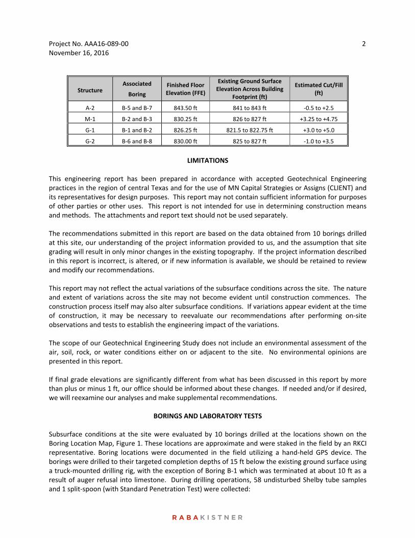
This engineering report has been prepared in accordance with accepted Geotechnical Engineering practices in the region of central Texas and for the use of MN Capital Strategies or Assigns (CLIENT) and its representatives for design purposes. This report may not contain sufficient information for purposes of other parties or other uses. This report is not intended for use in determining construction means and methods. The attachments and report text should not be used separately. The recommendations submitted in this report are based on the data obtained from 10 borings drilled at this site, our understanding of the project information provided to us, and the assumption that site grading will result in only minor changes in the existing topography. If the project information described in this report is incorrect, is altered, or if new information is available, we should be retained to review and modify our recommendations. This report may not reflect the actual variations of the subsurface conditions across the site. The nature and extent of variations across the site may not become evident until construction commences. The construction process itself may also alter subsurface conditions. If variations appear evident at the time of construction, it may be necessary to reevaluate our recommendations after performing on‐site observations and tests to establish the engineering impact of the variations. The scope of our Geotechnical Engineering Study does not include an environmental assessment of the air, soil, rock, or water conditions either on or adjacent to the site. No environmental opinions are presented in this report. If final grade elevations are significantly different from what has been discussed in this report by more than plus or minus 1 ft, our office should be informed about these changes. If needed and/or if desired, we will reexamine our analyses and make supplemental recommendations.
BORINGS AND LABORATORY TESTS Subsurface conditions at the site were evaluated by 10 borings drilled at the locations shown on the Boring Location Map, Figure 1. These locations are approximate and were staked in the field by an RKCI representative. Boring locations were documented in the field utilizing a hand‐held GPS device. The borings were drilled to their targeted completion depths of 15 ft below the existing ground surface using a truck‐mounted drilling rig, with the exception of Boring B‐1 which was terminated at about 10 ft as a result of auger refusal into limestone. During drilling operations, 58 undisturbed Shelby tube samples and 1 split‐spoon (with Standard Penetration Test) were collected:
Structure Associated
Boring
Finished Floor Elevation (FFE)
Existing Ground Surface Elevation Across Building
Footprint (ft)
Estimated Cut/Fill (ft)
A‐2 B‐5 and B‐7 843.50 ft 841 to 843 ft ‐0.5 to +2.5
M‐1 B‐2 and B‐3 830.25 ft 826 to 827 ft +3.25 to +4.75
G‐1 B‐1 and B‐2 826.25 ft 821.5 to 822.75 ft +3.0 to +5.0
G‐2 B‐6 and B‐8 830.00 ft 825 to 827 ft ‐1.0 to +3.5
Project No. AAA16‐089‐00 November 16, 2016
3
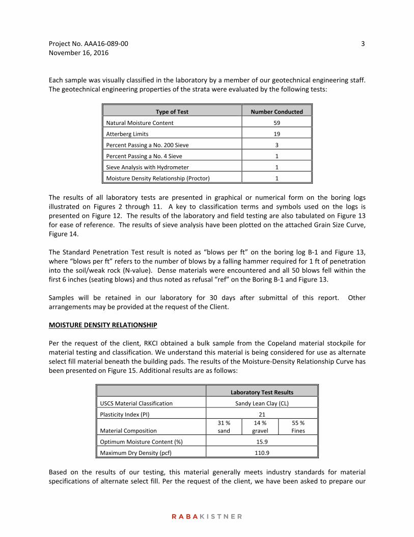
Each sample was visually classified in the laboratory by a member of our geotechnical engineering staff. The geotechnical engineering properties of the strata were evaluated by the following tests:
Type of Test Number Conducted
Natural Moisture Content 59
Atterberg Limits 19
Percent Passing a No. 200 Sieve 3
Percent Passing a No. 4 Sieve 1
Sieve Analysis with Hydrometer 1
Moisture Density Relationship (Proctor) 1
The results of all laboratory tests are presented in graphical or numerical form on the boring logs illustrated on Figures 2 through 11. A key to classification terms and symbols used on the logs is presented on Figure 12. The results of the laboratory and field testing are also tabulated on Figure 13 for ease of reference. The results of sieve analysis have been plotted on the attached Grain Size Curve, Figure 14. The Standard Penetration Test result is noted as “blows per ft” on the boring log B‐1 and Figure 13, where “blows per ft” refers to the number of blows by a falling hammer required for 1 ft of penetration into the soil/weak rock (N‐value). Dense materials were encountered and all 50 blows fell within the first 6 inches (seating blows) and thus noted as refusal “ref” on the Boring B‐1 and Figure 13. Samples will be retained in our laboratory for 30 days after submittal of this report. Other arrangements may be provided at the request of the Client. MOISTURE DENSITY RELATIONSHIP Per the request of the client, RKCI obtained a bulk sample from the Copeland material stockpile for material testing and classification. We understand this material is being considered for use as alternate select fill material beneath the building pads. The results of the Moisture‐Density Relationship Curve has been presented on Figure 15. Additional results are as follows:
Laboratory Test Results
USCS Material Classification Sandy Lean Clay (CL)
Plasticity Index (PI) 21
Material Composition 31 % sand
14 % gravel
55 % Fines
Optimum Moisture Content (%) 15.9
Maximum Dry Density (pcf) 110.9
Based on the results of our testing, this material generally meets industry standards for material specifications of alternate select fill. Per the request of the client, we have been asked to prepare our
Project No. AAA16‐089‐00 November 16, 2016
4
foundation recommendations assuming this and/or similar material will be utilized as fill grading in the building areas.
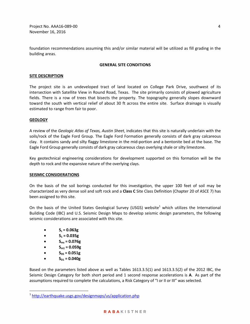
GENERAL SITE CONDITIONS SITE DESCRIPTION The project site is an undeveloped tract of land located on College Park Drive, southwest of its intersection with Satellite View in Round Road, Texas. The site primarily consists of plowed agriculture fields. There is a row of trees that bisects the property. The topography generally slopes downward toward the south with vertical relief of about 30 ft across the entire site. Surface drainage is visually estimated to range from fair to poor. GEOLOGY A review of the Geologic Atlas of Texas, Austin Sheet, indicates that this site is naturally underlain with the soils/rock of the Eagle Ford Group. The Eagle Ford Formation generally consists of dark gray calcareous clay. It contains sandy and silty flaggy limestone in the mid‐portion and a bentonite bed at the base. The Eagle Ford Group generally consists of dark gray calcareous clays overlying shale or silty limestone. Key geotechnical engineering considerations for development supported on this formation will be the depth to rock and the expansive nature of the overlying clays. SEISMIC CONSIDERATIONS On the basis of the soil borings conducted for this investigation, the upper 100 feet of soil may be characterized as very dense soil and soft rock and a Class C Site Class Definition (Chapter 20 of ASCE 7) has been assigned to this site. On the basis of the United States Geological Survey (USGS) website1 which utilizes the International Building Code (IBC) and U.S. Seismic Design Maps to develop seismic design parameters, the following seismic considerations are associated with this site.
Ss = 0.063g
S1 = 0.035g
Sms = 0.076g
Sm1 = 0.059g
SDS = 0.051g
SD1 = 0.040g Based on the parameters listed above as well as Tables 1613.3.5(1) and 1613.3.5(2) of the 2012 IBC, the Seismic Design Category for both short period and 1 second response accelerations is A. As part of the assumptions required to complete the calculations, a Risk Category of “I or II or III” was selected.
1 http://earthquake.usgs.gov/designmaps/us/application.php
Project No. AAA16‐089‐00 November 16, 2016
5
STRATIGRAPHY
The subsurface conditions encountered at the boring locations are shown on the boring logs, Figures 2 through 11. These boring logs represent our interpretation of the subsurface conditions based on the field logs, visual examination of field samples by our personnel, and test results of selected field samples. Each stratum has been designated by grouping soils that possess similar physical and engineering characteristics. The lines designating the interfaces between strata on the boring logs represent approximate boundaries. Transitions between strata may be gradual.
Stratum I consists of dark brown to brown fat clay (CH), with calcareous deposits. These clays are classified as plastic to highly plastic based on measured plasticity indices ranging from 29 to 59. Measured moisture contents range from 20 to 30 percent. Shear strength ranges from 2.0 to 2.3 tsf based on pocket penetrometer test data. Approximately, 89 percent of the fines passed a No. 200 sieve.
Stratum II consists of hard, tan to tan and gray fat clay (CH) with calcareous deposits. These clays are classified as plastic to highly plastic based on measured plasticity indices of 27 to 70. Measured moisture contents range from 15 to 37 percent. Shear strength of 2.3 tsf were measured based on pocket penetrometer test data. Approximately, 83 percent of the fines passed a No. 200 sieve.
A clayey sand layer was encountered in Boring B‐5 at an approximate depth of 8 ft below the ground surface. This sample has a measured moisture content of 16 percent and a PI of 27. Approximately, 21 percent of this fines in this sample passed a No. 200 sieve.
Stratum III consists of hard, tan limestone. A single measured moisture content of 1 percent was determined in this stratum. Standard penetration test results in refusal for zero penetration in this stratum. This stratum was only encountered in Boring B‐1 at an approximate depth of 8 ft below the ground surface.
GROUNDWATER
Groundwater was not observed in the borings either during or immediately upon completion of the drilling operations. All borings remained dry during the field exploration phase. However, it is possible for groundwater to exist beneath this site at shallow depths on a transient basis, particularly following periods of precipitation. Fluctuations in groundwater levels occur due to variation in rainfall and surface water run‐off. The construction process itself may also cause variations in the groundwater level.
FOUNDATION ANALYSIS
EXPANSIVE SOIL‐RELATED MOVEMENTS
The anticipated ground movements due to swelling of the underlying soils at the site were estimated for slab‐on‐grade construction using the empirical procedure, Texas Department of Transportation (TxDOT) Tex‐124‐E, Method for Determining the Potential Vertical Rise (PVR). PVR values on the order of 4‐1/2 to 6 inches were estimated for stratigraphic conditions. The estimated range in PVR incorporates proposed (‐) cut/(+) fill anticipated within the building footprints. A surcharge load of 1 psi (concrete slab and sand layer), an active zone of 15 ft and dry moisture conditions were assumed in estimating the above PVR values.
Project No. AAA16‐089‐00 November 16, 2016
6
The TxDOT method of estimating expansive soil‐related movements is based on empirical correlations utilizing the measured plasticity indices and assuming typical seasonal fluctuations in moisture content. If desired, other methods of estimating expansive soil‐related movements are available, such as estimations based on swell tests and/or soil‐suction analyses. However, the performance of these tests and the detailed analysis of expansive soil‐related movements were beyond the scope of the current study. It should also be noted that actual movements can exceed the calculated PVR values due to isolated changes in moisture content or if water seeps into the soils to greater depths than the assumed active zone depth due to deep trenching or excavations.
OPTIONS FOR REDUCING EXPANSIVE SOIL‐RELATED MOVEMENTS
Option 1: Overexcavation and Select Fill Replacement
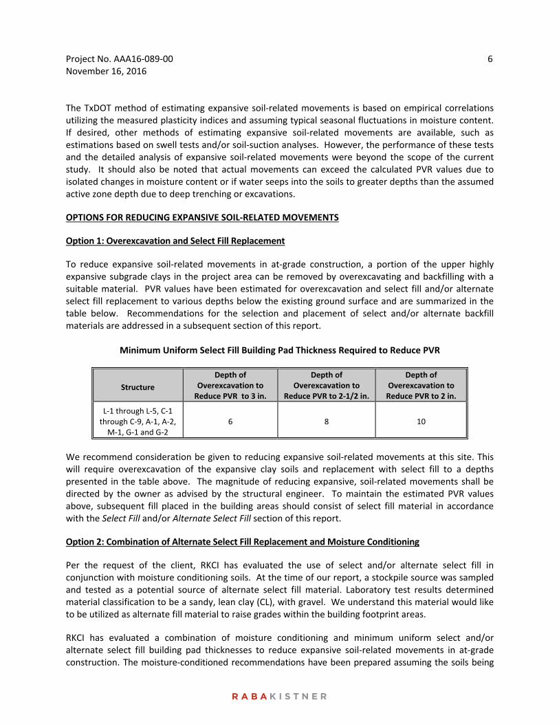
To reduce expansive soil‐related movements in at‐grade construction, a portion of the upper highly expansive subgrade clays in the project area can be removed by overexcavating and backfilling with a suitable material. PVR values have been estimated for overexcavation and select fill and/or alternate select fill replacement to various depths below the existing ground surface and are summarized in the table below. Recommendations for the selection and placement of select and/or alternate backfill materials are addressed in a subsequent section of this report.
Minimum Uniform Select Fill Building Pad Thickness Required to Reduce PVR
Structure
Depth of Overexcavation to Reduce PVR to 3 in.
Depth of Overexcavation to
Reduce PVR to 2‐1/2 in.
Depth of Overexcavation to Reduce PVR to 2 in.
L‐1 through L‐5, C‐1 through C‐9, A‐1, A‐2, M‐1, G‐1 and G‐2
6 8 10
We recommend consideration be given to reducing expansive soil‐related movements at this site. This will require overexcavation of the expansive clay soils and replacement with select fill to a depths presented in the table above. The magnitude of reducing expansive, soil‐related movements shall be directed by the owner as advised by the structural engineer. To maintain the estimated PVR values above, subsequent fill placed in the building areas should consist of select fill material in accordance with the Select Fill and/or Alternate Select Fill section of this report.
Option 2: Combination of Alternate Select Fill Replacement and Moisture Conditioning
Per the request of the client, RKCI has evaluated the use of select and/or alternate select fill in conjunction with moisture conditioning soils. At the time of our report, a stockpile source was sampled and tested as a potential source of alternate select fill material. Laboratory test results determined material classification to be a sandy, lean clay (CL), with gravel. We understand this material would like to be utilized as alternate fill material to raise grades within the building footprint areas.
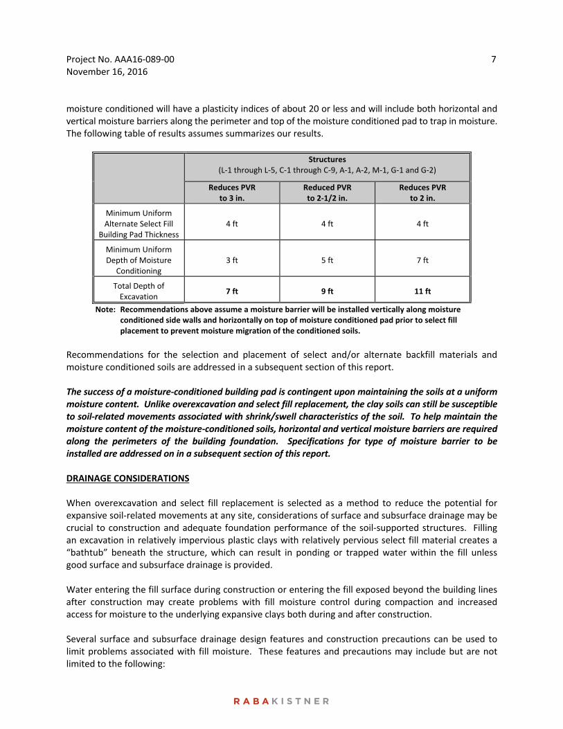
RKCI has evaluated a combination of moisture conditioning and minimum uniform select and/or alternate select fill building pad thicknesses to reduce expansive soil‐related movements in at‐grade construction. The moisture‐conditioned recommendations have been prepared assuming the soils being
Project No. AAA16‐089‐00 November 16, 2016
7
moisture conditioned will have a plasticity indices of about 20 or less and will include both horizontal and vertical moisture barriers along the perimeter and top of the moisture conditioned pad to trap in moisture. The following table of results assumes summarizes our results.
Structures (L‐1 through L‐5, C‐1 through C‐9, A‐1, A‐2, M‐1, G‐1 and G‐2)
Reduces PVR to 3 in.
Reduced PVR to 2‐1/2 in.
Reduces PVR to 2 in.
Minimum Uniform Alternate Select Fill
Building Pad Thickness 4 ft 4 ft 4 ft
Minimum Uniform Depth of Moisture
Conditioning 3 ft 5 ft 7 ft
Total Depth of Excavation
7 ft 9 ft 11 ft
Note: Recommendations above assume a moisture barrier will be installed vertically along moisture conditioned side walls and horizontally on top of moisture conditioned pad prior to select fill placement to prevent moisture migration of the conditioned soils.
Recommendations for the selection and placement of select and/or alternate backfill materials and moisture conditioned soils are addressed in a subsequent section of this report. The success of a moisture‐conditioned building pad is contingent upon maintaining the soils at a uniform moisture content. Unlike overexcavation and select fill replacement, the clay soils can still be susceptible to soil‐related movements associated with shrink/swell characteristics of the soil. To help maintain the moisture content of the moisture‐conditioned soils, horizontal and vertical moisture barriers are required along the perimeters of the building foundation. Specifications for type of moisture barrier to be installed are addressed on in a subsequent section of this report. DRAINAGE CONSIDERATIONS When overexcavation and select fill replacement is selected as a method to reduce the potential for expansive soil‐related movements at any site, considerations of surface and subsurface drainage may be crucial to construction and adequate foundation performance of the soil‐supported structures. Filling an excavation in relatively impervious plastic clays with relatively pervious select fill material creates a “bathtub” beneath the structure, which can result in ponding or trapped water within the fill unless good surface and subsurface drainage is provided. Water entering the fill surface during construction or entering the fill exposed beyond the building lines after construction may create problems with fill moisture control during compaction and increased access for moisture to the underlying expansive clays both during and after construction. Several surface and subsurface drainage design features and construction precautions can be used to limit problems associated with fill moisture. These features and precautions may include but are not limited to the following:
Project No. AAA16‐089‐00 November 16, 2016
8
Installing berms or swales on the uphill side of the construction area to divert surface runoff away from the excavation/fill area during construction;
Sloping of the top of the subgrade with a minimum downward slope of 1.5 percent out to the base of a dewatering trench located beyond the building perimeter;
Sloping the surface of the fill during construction to promote runoff of rain water to drainage features until the final lift is placed;
Sloping of a final, well maintained, impervious clay or pavement surface (downward away from the building) over the select fill material and any perimeter drain extending beyond the building lines, with a minimum gradient of 6 in. in 5 ft;
Constructing final surface drainage patterns to prevent ponding and limit surface water infiltration at and around the building perimeter;
Locating the water‐bearing utilities, roof drainage outlets and irrigation spray heads outside of the select fill and perimeter drain boundaries; and
Raising the elevation of the ground level floor slab. Details relative to the extent and implementation of these considerations must be evaluated on a project‐specific basis by all members of the project design team. Many variables that influence fill drainage considerations may depend on factors that are not fully developed in the early stages of design. For this reason, drainage of the fill should be given consideration at the earliest possible stages of the project.
FOUNDATION RECOMMENDATIONS SITE GRADING Site grading plans can result in changes in almost all aspects of foundation recommendations. We have prepared all foundation recommendations based on the provided grading plan, FFEs, and the stratigraphic conditions encountered at the time of our study. If site grading plans differ from what has been discussed in this report by more than plus or minus 1 ft, RKCI must be retained to review the site grading plans prior to bidding the project for construction. This will enable RKCI to provide input for any changes in our original recommendations that may be required as a result of site grading operations or other considerations. ENGINEERED BEAM AND SLAB FOUNDATION The apartment complex building structures may be supported on engineered beam and slab foundation, provided the selected foundation type can be designed to withstand the anticipated soil‐related movements (see Expansive Soil‐Related Movements) without impairing either the structural or the operational performance of the structure. Prior to site grading and concrete placement, we recommend implementing one of the Options for Reducing Expansive Soil‐Related Movements to reduce expansive soil‐related movements to tolerable limits. Allowable Bearing Capacity Shallow foundations founded on compacted, select fill and/or alternate select fill should be proportioned using the design parameters tabulated below.
Project No. AAA16‐089‐00 November 16, 2016
9
Minimum depth below final grade 10 in.
Minimum beam width 12 in.
Maximum allowable bearing pressure for grade beams constructed on a minimum of 4 ft of select and/or alternate select fill 2,200 psf
Maximum allowable bearing pressure for widened beams constructed on a minimum of 4 ft of select and/or alternate select fill 2,700 psf
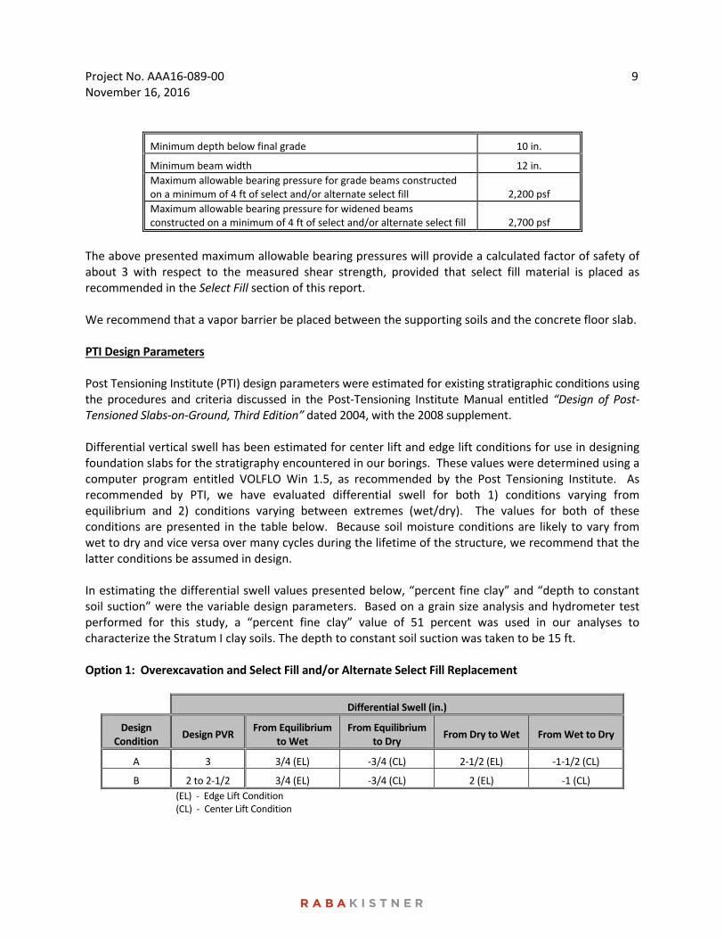
The above presented maximum allowable bearing pressures will provide a calculated factor of safety of about 3 with respect to the measured shear strength, provided that select fill material is placed as recommended in the Select Fill section of this report. We recommend that a vapor barrier be placed between the supporting soils and the concrete floor slab. PTI Design Parameters Post Tensioning Institute (PTI) design parameters were estimated for existing stratigraphic conditions using the procedures and criteria discussed in the Post‐Tensioning Institute Manual entitled “Design of Post‐Tensioned Slabs‐on‐Ground, Third Edition” dated 2004, with the 2008 supplement. Differential vertical swell has been estimated for center lift and edge lift conditions for use in designing foundation slabs for the stratigraphy encountered in our borings. These values were determined using a computer program entitled VOLFLO Win 1.5, as recommended by the Post Tensioning Institute. As recommended by PTI, we have evaluated differential swell for both 1) conditions varying from equilibrium and 2) conditions varying between extremes (wet/dry). The values for both of these conditions are presented in the table below. Because soil moisture conditions are likely to vary from wet to dry and vice versa over many cycles during the lifetime of the structure, we recommend that the latter conditions be assumed in design. In estimating the differential swell values presented below, “percent fine clay” and “depth to constant soil suction” were the variable design parameters. Based on a grain size analysis and hydrometer test performed for this study, a “percent fine clay” value of 51 percent was used in our analyses to characterize the Stratum I clay soils. The depth to constant soil suction was taken to be 15 ft. Option 1: Overexcavation and Select Fill and/or Alternate Select Fill Replacement
Differential Swell (in.)
Design Condition
Design PVR From Equilibrium
to Wet From Equilibrium
to Dry From Dry to Wet From Wet to Dry
A 3 3/4 (EL) ‐3/4 (CL) 2‐1/2 (EL) ‐1‐1/2 (CL)
B 2 to 2‐1/2 3/4 (EL) ‐3/4 (CL) 2 (EL) ‐1 (CL)
(EL) ‐ Edge Lift Condition (CL) ‐ Center Lift Condition
Project No. AAA16‐089‐00 November 16, 2016
10
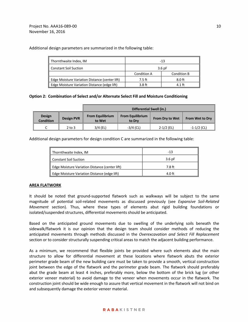
Additional design parameters are summarized in the following table:
Thornthwaite Index, IM ‐13
Constant Soil Suction 3.6 pF
Condition A Condition B
Edge Moisture Variation Distance (center lift) 7.5 ft 8.0 ft
Edge Moisture Variation Distance (edge lift) 3.8 ft 4.1 ft
Option 2: Combination of Select and/or Alternate Select Fill and Moisture Conditioning
Differential Swell (in.)
Design Condition
Design PVR From Equilibrium
to Wet From Equilibrium
to Dry From Dry to Wet From Wet to Dry
C 2 to 3 3/4 (EL) ‐3/4 (CL) 2‐1/2 (EL) ‐1‐1/2 (CL)
Additional design parameters for design condition C are summarized in the following table:
Thornthwaite Index, IM ‐13
Constant Soil Suction 3.6 pF
Edge Moisture Variation Distance (center lift) 7.8 ft
Edge Moisture Variation Distance (edge lift) 4.0 ft
AREA FLATWORK It should be noted that ground‐supported flatwork such as walkways will be subject to the same magnitude of potential soil‐related movements as discussed previously (see Expansive Soil‐Related Movement section). Thus, where these types of elements abut rigid building foundations or isolated/suspended structures, differential movements should be anticipated. Based on the anticipated ground movements due to swelling of the underlying soils beneath the sidewalk/flatwork it is our opinion that the design team should consider methods of reducing the anticipated movements through methods discussed in the Overexcavation and Select Fill Replacement section or to consider structurally suspending critical areas to match the adjacent building performance. As a minimum, we recommend that flexible joints be provided where such elements abut the main structure to allow for differential movement at these locations where flatwork abuts the exterior perimeter grade beam of the new building care must be taken to provide a smooth, vertical construction joint between the edge of the flatwork and the perimeter grade beam. The flatwork should preferably abut the grade beam at least 4 inches, preferably more, below the bottom of the brick lug (or other exterior veneer material) to avoid damage to the veneer when movements occur in the flatwork. The construction joint should be wide enough to assure that vertical movement in the flatwork will not bind on and subsequently damage the exterior veneer material.
Project No. AAA16‐089‐00 November 16, 2016
11
The construction joint should be completed using an appropriate elastomeric expansion joint filler to reduce the amount of water passing through the construction joint. Proper and regular maintenance of the expansion joint will help reduce the water seepage at the flatwork/foundation interface. A better option, if feasible, is to separate the flatwork away from the building foundation so that movements incurred by the flatwork are totally independent of the building foundation.
FOUNDATION CONSTRUCTION CONSIDERATIONS SITE DRAINAGE Drainage is an important key to the successful performance of any foundation. Good surface drainage should be established prior to and maintained after construction to help prevent water from ponding within or adjacent to the building foundation and to facilitate rapid drainage away from the building foundation. Failure to provide positive drainage away from the structure can result in localized differential vertical movements in soil supported foundations and floor slabs (which can in turn result in cracking in the sheetrock partition walls, as well as improper operation of windows and doors). Current ordinances, in compliance with the Americans with Disabilities Act (ADA), may dictate maximum slopes for walks and drives around and into new buildings. These slope requirements can result in drainage problems for buildings supported on expansive soils. We recommend that the maximum permissible slope be provided away from the building on all sides. Also to help control drainage in the vicinity of the structure, we recommend that roof/gutter downspouts and landscaping irrigation systems not be located adjacent to the building foundation. Where a select fill overbuild is provided outside of the floor slab/foundation footprint, the surface should be sealed with an impermeable layer (pavement or clay cap) to reduce infiltration of both irrigation and surface waters. Careful consideration should also be given to the location of water bearing utilities, as well as to provisions for drainage in the event of leaks in water bearing utilities. All leaks should be immediately repaired. Other drainage and subsurface drainage issues are discussed in the Expansive Soil‐Related Movements section of this report and under Pavement Construction Considerations. SITE PREPARATION Building areas and all areas to support select fill should be stripped of all vegetation and organic topsoil. Exposed subgrades should be thoroughly proofrolled in order to locate weak, compressible zones. A minimum of 5 passes of a fully‐loaded dump truck or a similar heavily‐loaded piece of construction equipment should be used for planning purposes. Proofrolling operations should be observed by the Geotechnical Engineer or their representative to document subgrade condition and preparation. Weak or soft areas identified during proofrolling should be removed and replaced with suitable, compacted on‐site clays, free of organics, oversized materials, and degradable or deleterious materials. Upon completion of the proofrolling operations and just prior to fill placement or slab construction, the exposed subgrade should be moisture conditioned by scarifying to a minimum depth of 6 inches and
Project No. AAA16‐089‐00 November 16, 2016
12
recompacting to a minimum of 95 percent of the maximum density determined from TxDOT, Tex‐114‐E, Compaction Test. The moisture content of the subgrade should be maintained within the range of optimum moisture content to 3 percentage points above optimum moisture content until permanently covered. MOISTURE CONDITIONING Moisture conditioning has been provided as an option to assist in minimizing expansive soil‐related movements. Prior to moisture conditioning, all vegetation should be stripped from the building pad area. Clay soils should be removed to a predetermined depth and replaced at a moisture content of 1 to 4 percentage points above the optimum moisture. We recommend that on‐site clay soils be placed in loose lifts not exceeding 8 inches in thickness and compacted to range of 92 to 98 percent of the maximum density as determined by TX DOT, Tex‐114E. PERIMETER MOISTURE BARRIER Vertical liner and horizontal liners should be installed along the side walls and top of the moisture condition building pad. The liner should be placed within a few feet of the foundation perimeter; however, care should be exercised not to compromise support of the concrete perimeter beam bearing support. The moisture barriers should extended to the depth of the moisture conditioned soils and/or perimeter bottom, which is expected to be about 3 ft, 5 ft or 7 ft depending on which PVR option is selected. The liner should also be comprised of a minimum 15‐mil thick PVC or EDPM sheeting. Care should be taken during construction and post construction to deter perforations, rips, and cuts of the moisture barrier. This could require eliminating planting trees, shrubs, or other requirements of excavations that could affect the integrity of the liner. If shallow landscaping plants are anticipated, placement of a 6‐inch thick mud slab placed on top of the liner could help to protect the liner from damages during shallow landscape planting excavations. Utility lines entering the building pad are points of moisture increase entry, as groundwater generally travels along these paths. To help minimize groundwater filtration, we recommend properly sealing the pipes if they intercept moisture barriers and also placing a clay plug around the utility pipe. SELECT FILL Materials used as select fill for final site grading preferably should be crushed stone or gravel aggregate. We recommend that materials specified for use as select fill meet the TxDOT 2014 Standard Specifications for Construction and Maintenance of Highways, Streets and Bridges, Item 247, Flexible Base, Type A, B, or C, Grades 1 through 3, and have a plasticity index between 7 and 20. Select fill should be placed in loose lifts not exceeding 8 in. in thickness and compacted to at least 95 percent of maximum density as determined by TxDOT, Tex‐113‐E, Compaction Test. The moisture content of the fill should be maintained within the range of 2 percentage points below to 2 percentage points above the optimum moisture content until final compaction.
Project No. AAA16‐089‐00 November 16, 2016
13
ALTERNATE SELECT FILL Alternatively, clayey gravel (GC), clayey sand (SC), or lean clays (CL) combination soils, as classified according to the Unified Soil Classification System (USCS), may be considered satisfactory for use as alternate select fill materials at this site. Alternative select fill materials shall have a maximum liquid limit not exceeding 40, a plasticity index between 7 and 20, and a maximum particle size not exceeding 4 in. or one‐half the loose lift thickness, whichever is smaller. In addition, if these materials are utilized, grain size analyses and Atterberg Limits must be performed during placement at a rate of one test each per 5,000 cubic yards of material due to the high degree of variability associated with pit‐run materials. If the above listed alternative materials are being considered for bidding purposes, the materials should be submitted to the Geotechnical Engineer for pre‐approval at a minimum of 10 working days or more prior to the bid date. Failure to do so will be the responsibility of the contractor. The contractor will also be responsible for ensuring that the properties of all delivered alternate select fill materials are similar to those of the pre‐approved submittal. It should also be noted that when using alternative fill materials, difficulties may be experienced with respect to moisture control during and subsequent to fill placement, as well as with erosion, particularly when exposed to inclement weather. This may result in sloughing of beam trenches and/or pumping of the fill materials. Soils classified as CH, MH, ML, SM, GM, OH, OL and Pt under the USCS are not considered suitable for use as select fill materials at this site. The native soils at this site are not considered suitable for use as select fill materials. Alternate select fill should be placed in loose lifts not exceeding 8 in. in thickness and compacted to at least 95 percent of maximum density as determined by TxDOT, Tex‐113‐E, Compaction Test. The moisture content of the fill should be maintained within the range of 2 percentage points below to 2 percentage points above the optimum moisture content until final compaction. SHALLOW FOUNDATION EXCAVATIONS Shallow foundation excavations should be observed by the Geotechnical Engineer or their representative prior to placement of reinforcing steel and concrete. This is necessary to observe that the bearing soils at the bottom of the excavations are similar to those encountered in our borings and that excessive loose materials and water are not present in the excavations. If soft pockets of soil are encountered in the foundation excavations, they should be removed and replaced with a compacted non‐expansive fill material or lean concrete up to the design foundation bearing elevations. EXCAVATION SLOPING AND BENCHING If utility trenches or other excavations extend to or below a depth of 5 ft below construction grade, the contractor or others shall be required to develop a trench safety plan to protect personnel entering the trench or trench vicinity. The collection of specific geotechnical data and the development of such a plan, which could include designs for sloping and benching or various types of temporary shoring, are beyond the scope of the current study. Any such designs and safety plans shall be developed in accordance with current OSHA guidelines and other applicable industry standards.
Project No. AAA16‐089‐00 November 16, 2016
14
EXCAVATION EQUIPMENT Our boring logs are not intended for use in determining construction means and methods and may therefore be misleading if used for that purpose. We recommend that earth‐work and utility contractors interested in bidding on the work perform their own tests in the form of test pits to determine the quantities of the different materials to be excavated, as well as the preferred excavation methods and equipment for this site. UTILITIES Utilities which project through slab‐on‐grade, slab‐on‐fill, or any other rigid unit should be designed with either some degree of flexibility or with sleeves. Such design features will help reduce the risk of damage to the utility lines as vertical movements occur. Our experience indicates that significant settlement of backfill can occur in utility trenches, particularly when trenches are deep, when backfill materials are placed in thick lifts with insufficient compaction, and when water can access and infiltrate the trench backfill materials. The potential for water to access the backfill is increased where water can infiltrate flexible base materials due to insufficient penetration of curbs, and at sites where geological features can influence water migration into utility trenches (such as fractures within a rock mass or at contacts between rock and clay formations). It is our belief that another factor which can significantly impact settlement is the migration of fines within the backfill into the open voids in the underlying free‐draining bedding material. To reduce the potential for settlement in utility trenches, we recommend that consideration be given to the following:
All backfill materials should be placed and compacted in controlled lifts appropriate for the type of backfill and the type of compaction equipment being utilized and all backfilling procedures should be tested and documented. Trench backfill materials should be placed in loose lifts not exceeding 8 inches in thickness and compacted to at least 95 percent of maximum density as determined by TxDOT, Tex‐113‐E or Tex‐114‐E, Compaction Test. The moisture content of the fill should be maintained within the range of 2 percentage points below to 2 percentage points above the optimum moisture content for non‐cohesive soils and maintained within the range of optimum to 3 percentage points above optimum moisture content for cohesive soils until final compaction.
Curbs should completely penetrate base materials and be installed to a sufficient depth to reduce water infiltration beneath the curbs into the pavement base materials.
Consideration should be given to wrapping free‐draining bedding gravels with a geotextile fabric (similar to Mirafi 140N) to reduce the infiltration and loss of fines from backfill material into the interstitial voids in bedding materials.
PAVEMENT RECOMMENDATIONS
Recommendations for both flexible and rigid pavements are presented in this report. The Owner and/or design team may select either pavement type depending on the performance criteria established for the project. In general, flexible pavement systems have a lower initial construction cost as compared to
Project No. AAA16‐089‐00 November 16, 2016
15
rigid pavements. However, maintenance requirements over the life of the pavement are typically much greater for flexible pavements. This typically requires regularly scheduled observation and repair, as well as overlays and/or other pavement rehabilitation at approximately one‐half to two‐thirds of the design life. Rigid pavements are generally more "forgiving", and therefore tend to be more durable and require less maintenance after construction. For either pavement type, drainage conditions will have a significant impact on long term performance, particularly where permeable base materials are utilized in the pavement section. Drainage considerations are discussed in more detail in a subsequent section of this report. SUBGRADE CONDITIONS We have assumed the subgrade in pavement areas will consist of either the Stratum I dark brown clays, Stratum II tan clays, or recompacted on‐site clays, placed and compacted as recommended in the On‐Site Clay Fill section of this report. Based on our experience with similar subgrade soils, we have assigned California Bearing Ratio (CBR) values of 3.0 for Stratum I clays and re‐compacted on‐site clays for use in pavement thickness design analyses. DESIGN INFORMATION The following recommendations were prepared using the DARWin 3.1 software program which utilizes a procedure based on the 1993 “Guide for the Design of Pavement Structures” by the American Association of State Highway and Transportation Officials (AASHTO). The following recommendations were prepared assuming a 20‐yr design life and Equivalent Single Axle Loads (ESAL’s) of 20,000 for light duty pavements and 80,000 for medium duty pavements. This traffic frequency is approximately equivalent to 1 and 3 tractor‐trailer trucks per day for a design period of 20 years for light and heavy duty pavements, respectively. The Project Civil Engineer should review anticipated traffic loading and frequencies to verify that the assumed traffic loading and frequency is appropriate for the intended use of the facility. FLEXIBLE PAVEMENT
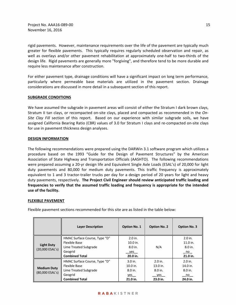
Flexible pavement sections recommended for this site are as listed in the table below:
Layer Description Option No. 1 Option No. 2 Option No. 3
Light Duty (20,000 ESAL’s)
HMAC Surface Course, Type “D” Flexible Base Lime Treated Subgrade Geogrid Combined Total
2.0 in. 10.0 in. 8.0 in. __yes__ 20.0 in.
N/A
2.0 in. 11.0 in. 8.0 in. _ no _
21.0 in.
Medium Duty (80,000 ESAL’s)
HMAC Surface Course, Type “D” Flexible Base Lime Treated Subgrade Geogrid Combined Total
3.0 in. 10.0 in. 8.0 in. yes__ 21.0 in.
2.0 in. 13.0 in. 8.0 in.
__ yes__ 23.0 in.
2.0 in. 14.0 in. 8.0 in. __no__ 24.0 in.
Project No. AAA16‐089‐00 November 16, 2016
16
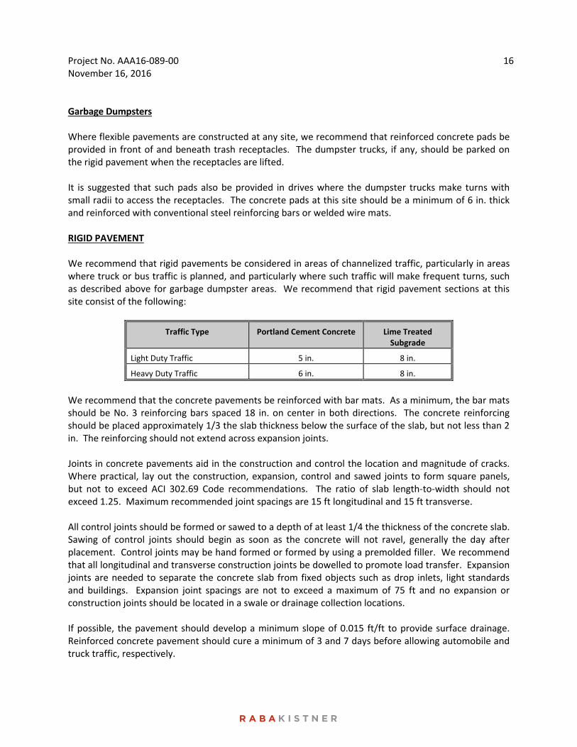
Garbage Dumpsters Where flexible pavements are constructed at any site, we recommend that reinforced concrete pads be provided in front of and beneath trash receptacles. The dumpster trucks, if any, should be parked on the rigid pavement when the receptacles are lifted. It is suggested that such pads also be provided in drives where the dumpster trucks make turns with small radii to access the receptacles. The concrete pads at this site should be a minimum of 6 in. thick and reinforced with conventional steel reinforcing bars or welded wire mats. RIGID PAVEMENT We recommend that rigid pavements be considered in areas of channelized traffic, particularly in areas where truck or bus traffic is planned, and particularly where such traffic will make frequent turns, such as described above for garbage dumpster areas. We recommend that rigid pavement sections at this site consist of the following:
Traffic Type Portland Cement Concrete Lime Treated Subgrade
Light Duty Traffic 5 in. 8 in.
Heavy Duty Traffic 6 in. 8 in.
We recommend that the concrete pavements be reinforced with bar mats. As a minimum, the bar mats should be No. 3 reinforcing bars spaced 18 in. on center in both directions. The concrete reinforcing should be placed approximately 1/3 the slab thickness below the surface of the slab, but not less than 2 in. The reinforcing should not extend across expansion joints. Joints in concrete pavements aid in the construction and control the location and magnitude of cracks. Where practical, lay out the construction, expansion, control and sawed joints to form square panels, but not to exceed ACI 302.69 Code recommendations. The ratio of slab length‐to‐width should not exceed 1.25. Maximum recommended joint spacings are 15 ft longitudinal and 15 ft transverse. All control joints should be formed or sawed to a depth of at least 1/4 the thickness of the concrete slab. Sawing of control joints should begin as soon as the concrete will not ravel, generally the day after placement. Control joints may be hand formed or formed by using a premolded filler. We recommend that all longitudinal and transverse construction joints be dowelled to promote load transfer. Expansion joints are needed to separate the concrete slab from fixed objects such as drop inlets, light standards and buildings. Expansion joint spacings are not to exceed a maximum of 75 ft and no expansion or construction joints should be located in a swale or drainage collection locations. If possible, the pavement should develop a minimum slope of 0.015 ft/ft to provide surface drainage. Reinforced concrete pavement should cure a minimum of 3 and 7 days before allowing automobile and truck traffic, respectively.
Project No. AAA16‐089‐00 November 16, 2016
17
PAVEMENT CONSTRUCTION CONSIDERATIONS SUBGRADE PREPARATION Areas to support pavements should be stripped of all vegetation and organic topsoil and the exposed subgrade should be proofrolled in accordance with the recommendations in the Site Preparation section under Foundation Construction Considerations. After completion of the proofrolling operations and just prior to flexible base placement, the exposed subgrade should be moisture conditioned by scarifying to a minimum depth of 6 in. and recompacting to a minimum of 95 percent of the maximum density determined from the Texas Department of Transportation Compaction Test (TxDOT, Tex‐114‐E). The moisture content of the subgrade should be maintained within the range of optimum moisture content to 3 percentage points above optimum until permanently covered. DRAINAGE CONSIDERATIONS As with any soil‐supported structure, the satisfactory performance of a pavement system is contingent on the provision of adequate surface and subsurface drainage. Insufficient drainage which allows saturation of the pavement subgrade and/or the supporting granular pavement materials will greatly reduce the performance and service life of the pavement systems. Surface and subsurface drainage considerations crucial to the performance of pavements at this site include (but are not limited to) the following:
1) Any known natural or man‐made subsurface seepage at the site which may occur at sufficiently shallow depths as to influence moisture contents within the subgrade should be intercepted by drainage ditches or below grade French drains.
2) Final site grading should eliminate isolated depressions adjacent to curbs which may allow surface water to pond and infiltrate into the underlying soils. Curbs should completely penetrate base materials and should be installed to sufficient depth to reduce infiltration of water beneath the curbs.
3) Pavement surfaces should be maintained to help minimize surface ponding and to provide rapid sealing of any developing cracks. These measures will help reduce infiltration of surface water downward through the pavement section.
ON‐SITE CLAY FILL The pavement recommendations presented in this report were prepared assuming that on‐site soils will be used for fill grading in proposed pavement areas. If used, we recommend that on‐site soils be placed in loose lifts not exceeding 8 in. in thickness and compacted to at least 95 percent of the maximum density as determined by TxDOT, Tex‐114‐E. The moisture content of the fill should be maintained within the range of optimum water content to 3 percentage points above the optimum water content until permanently covered. We recommend that fill materials be free of roots and other organic or degradable material. We also recommend that the maximum particle size not exceed 4 in. or one half the lift thickness, whichever is smaller.
Project No. AAA16‐089‐00 November 16, 2016
18
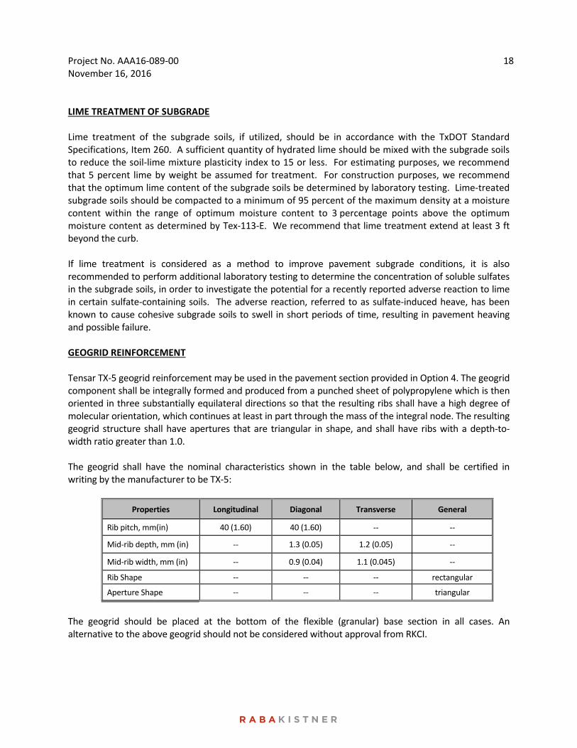
LIME TREATMENT OF SUBGRADE Lime treatment of the subgrade soils, if utilized, should be in accordance with the TxDOT Standard Specifications, Item 260. A sufficient quantity of hydrated lime should be mixed with the subgrade soils to reduce the soil‐lime mixture plasticity index to 15 or less. For estimating purposes, we recommend that 5 percent lime by weight be assumed for treatment. For construction purposes, we recommend that the optimum lime content of the subgrade soils be determined by laboratory testing. Lime‐treated subgrade soils should be compacted to a minimum of 95 percent of the maximum density at a moisture content within the range of optimum moisture content to 3 percentage points above the optimum moisture content as determined by Tex‐113‐E. We recommend that lime treatment extend at least 3 ft beyond the curb. If lime treatment is considered as a method to improve pavement subgrade conditions, it is also recommended to perform additional laboratory testing to determine the concentration of soluble sulfates in the subgrade soils, in order to investigate the potential for a recently reported adverse reaction to lime in certain sulfate‐containing soils. The adverse reaction, referred to as sulfate‐induced heave, has been known to cause cohesive subgrade soils to swell in short periods of time, resulting in pavement heaving and possible failure. GEOGRID REINFORCEMENT Tensar TX‐5 geogrid reinforcement may be used in the pavement section provided in Option 4. The geogrid component shall be integrally formed and produced from a punched sheet of polypropylene which is then oriented in three substantially equilateral directions so that the resulting ribs shall have a high degree of molecular orientation, which continues at least in part through the mass of the integral node. The resulting geogrid structure shall have apertures that are triangular in shape, and shall have ribs with a depth‐to‐width ratio greater than 1.0. The geogrid shall have the nominal characteristics shown in the table below, and shall be certified in writing by the manufacturer to be TX‐5:
Properties Longitudinal Diagonal Transverse General
Rib pitch, mm(in) 40 (1.60) 40 (1.60) ‐‐ ‐‐
Mid‐rib depth, mm (in) ‐‐ 1.3 (0.05) 1.2 (0.05) ‐‐
Mid‐rib width, mm (in) ‐‐ 0.9 (0.04) 1.1 (0.045) ‐‐
Rib Shape ‐‐ ‐‐ ‐‐ rectangular
Aperture Shape ‐‐ ‐‐ ‐‐ triangular
The geogrid should be placed at the bottom of the flexible (granular) base section in all cases. An alternative to the above geogrid should not be considered without approval from RKCI.
Project No. AAA16‐089‐00 November 16, 2016
19
FLEXIBLE BASE COURSE The flexible base course should be crushed limestone conforming to TxDOT Standard Specifications, Item 247, Type A, Grades 1 or 2. Base course should be placed in lifts with a maximum thickness of 8 in. and compacted to a minimum of 100 percent of the maximum density at a moisture content within the range of 2 percentage points below to 2 percentage points above the optimum moisture content as determined by Tex‐113‐E. ASPHALTIC CONCRETE SURFACE COURSE The asphaltic concrete surface course should conform to TxDOT Standard Specifications, Item 340, Type D. The asphaltic concrete should be compacted to a minimum of 92 percent of the maximum theoretical specific gravity (Rice) of the mixture determined according to Test Method Tex‐227‐F. Pavement specimens, which shall be either cores or sections of asphaltic pavement, will be tested according to Test Method Tex‐207‐F. The nuclear‐density gauge or other methods which correlate satisfactorily with results obtained from project roadway specimens may be used when approved by the Engineer. Unless otherwise shown on the plans, the Contractor shall be responsible for obtaining the required roadway specimens at their expense and in a manner and at locations selected by the Engineer. PORTLAND CEMENT CONCRETE The Portland cement concrete should be air entrained to result in a 4 percent plus/minus 1 percent air, should have a maximum slump of 5 inches, and should have a minimum 28‐day compressive strength of 4,000 psi. A liquid membrane‐forming curing compound should be applied as soon as practical after broom finishing the concrete surface. The curing compound will help reduce the loss of water from the concrete. The reduction in the rapid loss in water will help reduce shrinkage cracking of the concrete.
CONSTRUCTION RELATED SERVICES CONSTRUCTION MATERIALS TESTING AND OBSERVATION SERVICES As presented in the attachment to this report, Important Information About Your Geotechnical Engineering Report, subsurface conditions can vary across a project site. The conditions described in this report are based on interpolations derived from a limited number of data points. Variations will be encountered during construction, and only the geotechnical design engineer will be able to determine if these conditions are different than those assumed for design. Construction problems resulting from variations or anomalies in subsurface conditions are among the most prevalent on construction projects and often lead to delays, changes, cost overruns, and disputes. These variations and anomalies can best be addressed if the geotechnical engineer of record, RKCI is retained to perform construction observation and testing services during the construction of the project. This is because:
RKCI has an intimate understanding of the geotechnical engineering report’s findings and recommendations. RKCI understands how the report should be interpreted and can provide such interpretations on site, on the client’s behalf.
Project No. AAA16‐089‐00 November 16, 2016
20
RKCI knows what subsurface conditions are anticipated at the site.
RKCI is familiar with the goals of the owner and project design professionals, having worked with them in the development of the geotechnical workscope. This enables RKCI to suggest remedial measures (when needed) which help meet the owner’s and the design teams’ requirements.
RKCI has a vested interest in client satisfaction, and thus assigns qualified personnel whose principal concern is client satisfaction. This concern is exhibited by the manner in which contractors’ work is tested, evaluated and reported, and in selection of alternative approaches when such may become necessary.
RKCI cannot be held accountable for problems which result due to misinterpretation of our findings or recommendations when we are not on hand to provide the interpretation which is required.
BUDGETING FOR CONSTRUCTION TESTING Appropriate budgets need to be developed for the required construction testing and observation activities. At the appropriate time before construction, we advise that RKCI and the project designers meet and jointly develop the testing budgets, as well as review the testing specifications as it pertains to this project. Once the construction testing budget and scope of work are finalized, we encourage a preconstruction meeting with the selected contractor to review the scope of work to make sure it is consistent with the construction means and methods proposed by the contractor. RKCI looks forward to the opportunity to provide continued support on this project, and would welcome the opportunity to meet with the Project Team to develop both a scope and budget for these services.
* * * * * * * * * * * * * * * * * *

ATTACHMENTS
!?
!?
!?
!?
!?
!?
!?
!?
!?
!?
G-1
C-4
A-2A-1C-8
L-4
L-3
L-5
C-6C-5
L-2
L-1
C-7
C-9C-1 C-2
C-3
G-2
SATELLITE VIEW
COLLEGE PARK DRIVE
CAMP
US VI
LLAGE
DRIVE
B-9
B-8
B-7
B-6
B-5
B-4
B-3
B-2
B-1
B-10
BORING LOCATION MAPROUND ROCK APARTMENTS
SW INTERSECTION OF COLLEGE PARK DRIVE AND SATELLITE VIEWROUND ROCK, TEXAS
PROJECT No.:AAA16-089-00DRAWN BY:ISSUE DATE:
REVIEWED BY:CHECKED BY:
KRB11/07/2016
YGTRTS
NOTE: This Drawing is Provided for Illustration Only, May Not be to Scale and is Not Suitable for Design or Construction Purposes
µ
Austin
GeorgetownGeorgetown
§̈¦35
§̈¦35
£¤79
UV29
Williamson
TravisSITE LOCATION MAP
S I T E
FIGURE1WILLIAMSON
COUNTY
_̂
TBPE Firm Number 3257
8100 Cameron Road, Suite B-150Austin, Texas 78754(512)339-1745 TEL(512)339-6174 FAX
www.rkci.com
LEGEND!? BORING
PROPOSED STRUCTUREPROPOSED PARKING GARAGEPROPOSED PAVEMENT
0 100 20050FEET
1 INCH = 200 FEET
SOURCE: Aerial Photograph Obtained from the Google Earth Pro - 2016
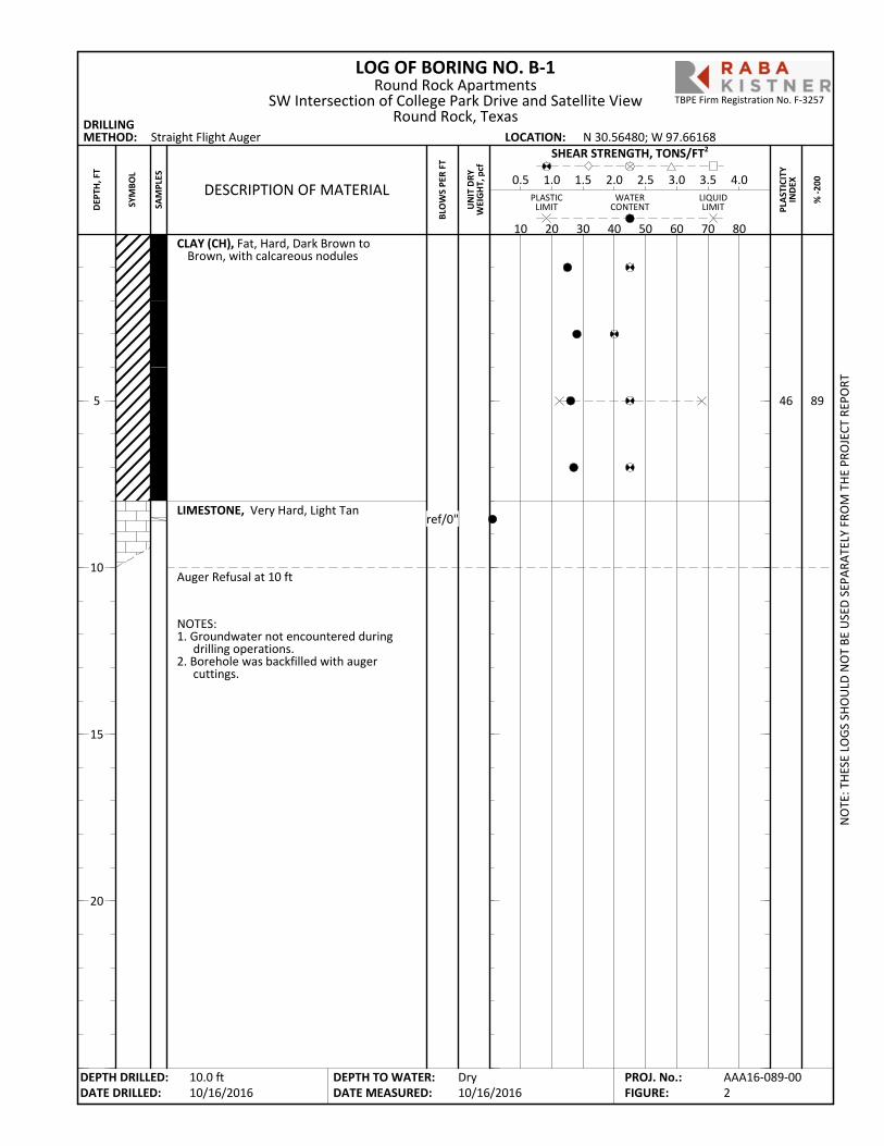
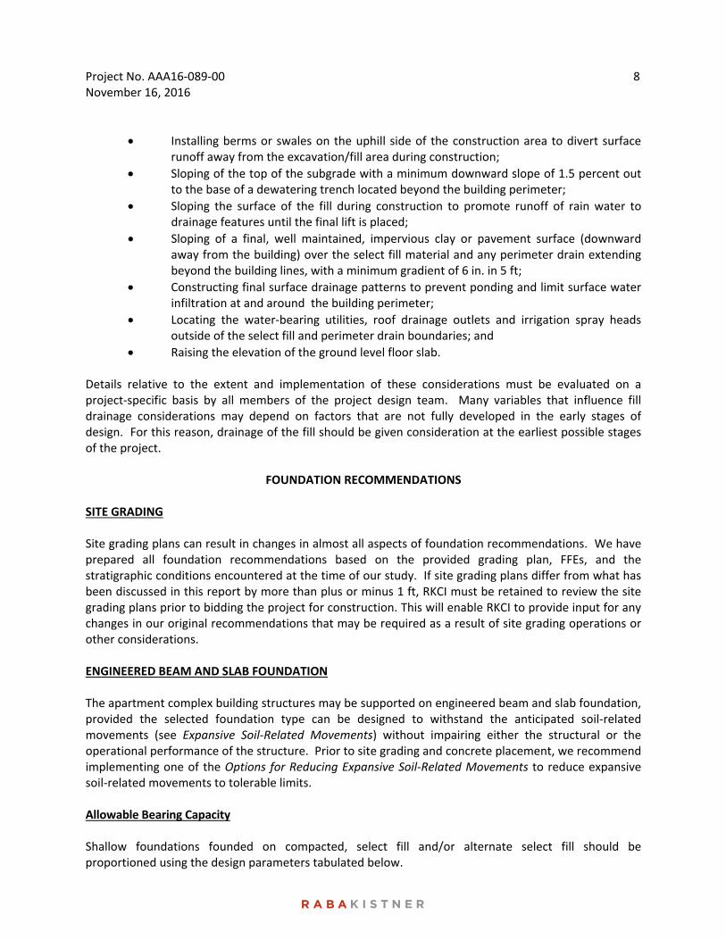
CLAY (CH), Fat, Hard, Dark Brown toBrown, with calcareous nodules
LIMESTONE, Very Hard, Light Tan
Auger Refusal at 10 ft
46
NOTES:1. Groundwater not encountered during
drilling operations.2. Borehole was backfilled with auger
cuttings.
89
LOG OF BORING NO. B-1
PLA
STIC
ITY
IND
EX
Straight Flight Auger
% -2
00
DRILLINGMETHOD: LOCATION:
PLASTICLIMIT
LIQUIDLIMIT
WATERCONTENT
BLO
WS
PER
FT
10 20 30 40 50 60 70 80
DESCRIPTION OF MATERIAL0.5 1.0 1.5 2.0 2.5 3.0 3.5 4.0
SHEAR STRENGTH, TONS/FT2
UN
IT D
RYW
EIG
HT,
pcf
N 30.56480; W 97.66168
NO
TE: T
HES
E LO
GS
SHO
ULD
NO
T BE
USE
D S
EPAR
ATEL
Y FR
OM
TH
E PR
OJE
CT R
EPO
RT
DEPTH DRILLED:DATE DRILLED:
DEPTH TO WATER:DATE MEASURED:
5
10
15
20
SYM
BOL
SAM
PLES
Round Rock ApartmentsSW Intersection of College Park Drive and Satellite View
Round Rock, Texas
Dry10/16/2016
DEP
TH, F
T
10.0 ft10/16/2016
AAA16-089-002
PROJ. No.:FIGURE:
TBPE Firm Registration No. F-3257
ref/0"

CLAY (CH), Fat, Hard, Dark Brown toBrown, with calcareous nodules
CLAY (CH), Fat, Hard, Tan and Brown, withcalcareous nodules
Boring Terminated
49
51
41
NOTES:1. Groundwater not encountered during
drilling operations.2. Borehole was backfilled with auger
cuttings.
LOG OF BORING NO. B-2
PLA
STIC
ITY
IND
EX
Straight Flight Auger
% -2
00
DRILLINGMETHOD: LOCATION:
PLASTICLIMIT
LIQUIDLIMIT
WATERCONTENT
BLO
WS
PER
FT
10 20 30 40 50 60 70 80
DESCRIPTION OF MATERIAL0.5 1.0 1.5 2.0 2.5 3.0 3.5 4.0
SHEAR STRENGTH, TONS/FT2
UN
IT D
RYW
EIG
HT,
pcf
N 30.56541; W 97.66149
NO
TE: T
HES
E LO
GS
SHO
ULD
NO
T BE
USE
D S
EPAR
ATEL
Y FR
OM
TH
E PR
OJE
CT R
EPO
RT
DEPTH DRILLED:DATE DRILLED:
DEPTH TO WATER:DATE MEASURED:
5
10
15
20
SYM
BOL
SAM
PLES
Round Rock ApartmentsSW Intersection of College Park Drive and Satellite View
Round Rock, Texas
Dry10/16/2016
DEP
TH, F
T
15.0 ft10/16/2016
AAA16-089-003
PROJ. No.:FIGURE:
TBPE Firm Registration No. F-3257
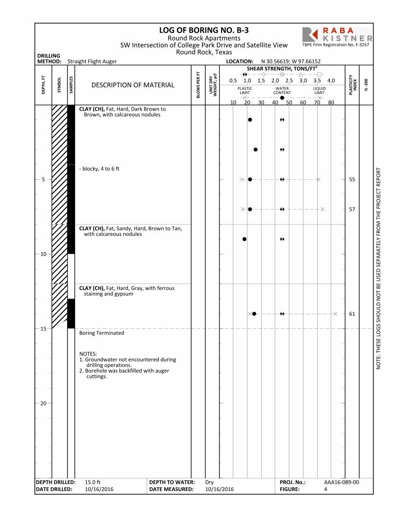
CLAY (CH), Fat, Hard, Dark Brown toBrown, with calcareous nodules
- blocky, 4 to 6 ft
CLAY (CH), Fat, Sandy, Hard, Brown to Tan,with calcareous nodules
CLAY (CH), Fat, Hard, Gray, with ferrousstaining and gypsum
Boring Terminated
55
57
61
NOTES:1. Groundwater not encountered during
drilling operations.2. Borehole was backfilled with auger
cuttings.
LOG OF BORING NO. B-3
PLA
STIC
ITY
IND
EX
Straight Flight Auger
% -2
00
DRILLINGMETHOD: LOCATION:
PLASTICLIMIT
LIQUIDLIMIT
WATERCONTENT
BLO
WS
PER
FT
10 20 30 40 50 60 70 80
DESCRIPTION OF MATERIAL0.5 1.0 1.5 2.0 2.5 3.0 3.5 4.0
SHEAR STRENGTH, TONS/FT2
UN
IT D
RYW
EIG
HT,
pcf
N 30.56619; W 97.66152
NO
TE: T
HES
E LO
GS
SHO
ULD
NO
T BE
USE
D S
EPAR
ATEL
Y FR
OM
TH
E PR
OJE
CT R
EPO
RT
DEPTH DRILLED:DATE DRILLED:
DEPTH TO WATER:DATE MEASURED:
5
10
15
20
SYM
BOL
SAM
PLES
Round Rock ApartmentsSW Intersection of College Park Drive and Satellite View
Round Rock, Texas
Dry10/16/2016
DEP
TH, F
T
15.0 ft10/16/2016
AAA16-089-004
PROJ. No.:FIGURE:
TBPE Firm Registration No. F-3257
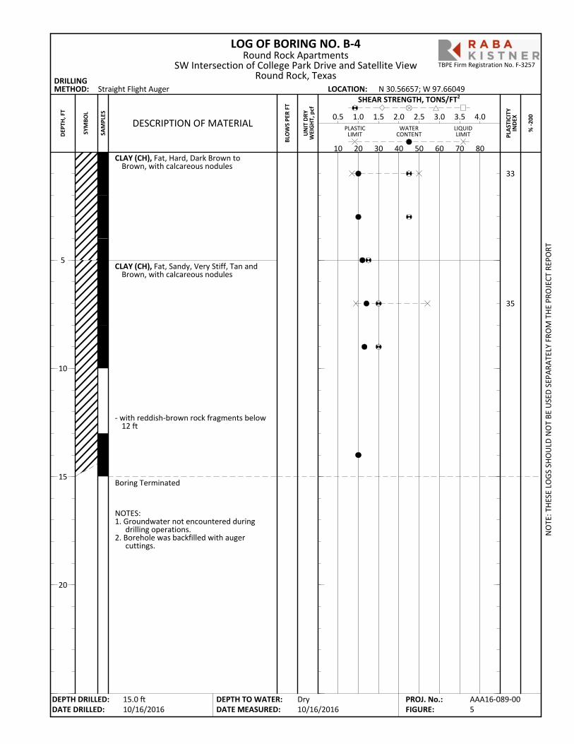
CLAY (CH), Fat, Hard, Dark Brown toBrown, with calcareous nodules
CLAY (CH), Fat, Sandy, Very Stiff, Tan andBrown, with calcareous nodules
- with reddish-brown rock fragments below12 ft
Boring Terminated
33
35
NOTES:1. Groundwater not encountered during
drilling operations.2. Borehole was backfilled with auger
cuttings.
LOG OF BORING NO. B-4
PLA
STIC
ITY
IND
EX
Straight Flight Auger
% -2
00
DRILLINGMETHOD: LOCATION:
PLASTICLIMIT
LIQUIDLIMIT
WATERCONTENT
BLO
WS
PER
FT
10 20 30 40 50 60 70 80
DESCRIPTION OF MATERIAL0.5 1.0 1.5 2.0 2.5 3.0 3.5 4.0
SHEAR STRENGTH, TONS/FT2
UN
IT D
RYW
EIG
HT,
pcf
N 30.56657; W 97.66049
NO
TE: T
HES
E LO
GS
SHO
ULD
NO
T BE
USE
D S
EPAR
ATEL
Y FR
OM
TH
E PR
OJE
CT R
EPO
RT
DEPTH DRILLED:DATE DRILLED:
DEPTH TO WATER:DATE MEASURED:
5
10
15
20
SYM
BOL
SAM
PLES
Round Rock ApartmentsSW Intersection of College Park Drive and Satellite View
Round Rock, Texas
Dry10/16/2016
DEP
TH, F
T
15.0 ft10/16/2016
AAA16-089-005
PROJ. No.:FIGURE:
TBPE Firm Registration No. F-3257

CLAY (CH), Fat, Hard, Dark Brown toBrown, with calcareous nodules
CLAY (CH), Fat, Sandy, Very Stiff to Hard,Tan and Brown, with light gray silty sandpartings and calcareous nodules
- grades to clayey sand with gravel, 8 to 10 ft
Boring Terminated
27
NOTES:1. Groundwater not encountered during
drilling operations.2. Borehole was backfilled with auger
cuttings.
87
21
LOG OF BORING NO. B-5
PLA
STIC
ITY
IND
EX
Straight Flight Auger
% -2
00
DRILLINGMETHOD: LOCATION:
PLASTICLIMIT
LIQUIDLIMIT
WATERCONTENT
BLO
WS
PER
FT
10 20 30 40 50 60 70 80
DESCRIPTION OF MATERIAL0.5 1.0 1.5 2.0 2.5 3.0 3.5 4.0
SHEAR STRENGTH, TONS/FT2
UN
IT D
RYW
EIG
HT,
pcf
N 30.56605; W 97.66013
NO
TE: T
HES
E LO
GS
SHO
ULD
NO
T BE
USE
D S
EPAR
ATEL
Y FR
OM
TH
E PR
OJE
CT R
EPO
RT
DEPTH DRILLED:DATE DRILLED:
DEPTH TO WATER:DATE MEASURED:
5
10
15
20
SYM
BOL
SAM
PLES
Round Rock ApartmentsSW Intersection of College Park Drive and Satellite View
Round Rock, Texas
Dry10/16/2016
DEP
TH, F
T
15.0 ft10/16/2016
AAA16-089-006
PROJ. No.:FIGURE:
TBPE Firm Registration No. F-3257
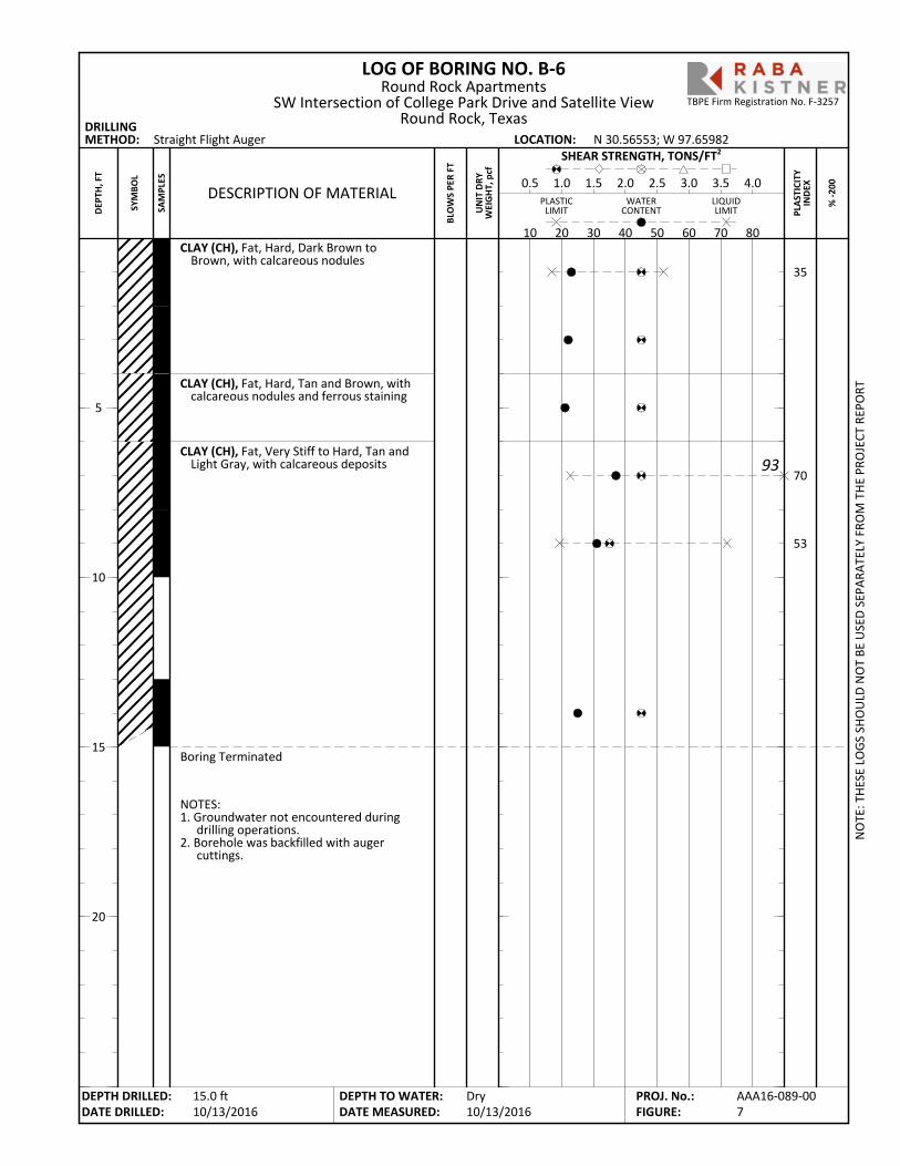
CLAY (CH), Fat, Hard, Dark Brown toBrown, with calcareous nodules
CLAY (CH), Fat, Hard, Tan and Brown, withcalcareous nodules and ferrous staining
CLAY (CH), Fat, Very Stiff to Hard, Tan andLight Gray, with calcareous deposits
Boring Terminated
35
70
53
NOTES:1. Groundwater not encountered during
drilling operations.2. Borehole was backfilled with auger
cuttings.
LOG OF BORING NO. B-6
PLA
STIC
ITY
IND
EX
Straight Flight Auger
% -2
00
DRILLINGMETHOD: LOCATION:
PLASTICLIMIT
LIQUIDLIMIT
WATERCONTENT
BLO
WS
PER
FT
10 20 30 40 50 60 70 80
DESCRIPTION OF MATERIAL0.5 1.0 1.5 2.0 2.5 3.0 3.5 4.0
SHEAR STRENGTH, TONS/FT2
UN
IT D
RYW
EIG
HT,
pcf
N 30.56553; W 97.65982
NO
TE: T
HES
E LO
GS
SHO
ULD
NO
T BE
USE
D S
EPAR
ATEL
Y FR
OM
TH
E PR
OJE
CT R
EPO
RT
DEPTH DRILLED:DATE DRILLED:
DEPTH TO WATER:DATE MEASURED:
5
10
15
20
SYM
BOL
SAM
PLES
Round Rock ApartmentsSW Intersection of College Park Drive and Satellite View
Round Rock, Texas
Dry10/13/2016
DEP
TH, F
T
15.0 ft10/13/2016
AAA16-089-007
PROJ. No.:FIGURE:
TBPE Firm Registration No. F-3257
93
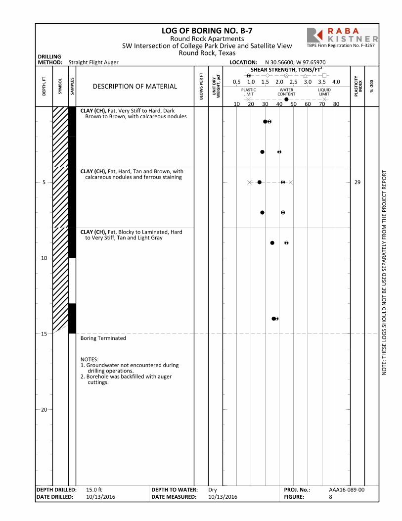
CLAY (CH), Fat, Very Stiff to Hard, DarkBrown to Brown, with calcareous nodules
CLAY (CH), Fat, Hard, Tan and Brown, withcalcareous nodules and ferrous staining
CLAY (CH), Fat, Blocky to Laminated, Hardto Very Stiff, Tan and Light Gray
Boring Terminated
29
NOTES:1. Groundwater not encountered during
drilling operations.2. Borehole was backfilled with auger
cuttings.
LOG OF BORING NO. B-7
PLA
STIC
ITY
IND
EX
Straight Flight Auger
% -2
00
DRILLINGMETHOD: LOCATION:
PLASTICLIMIT
LIQUIDLIMIT
WATERCONTENT
BLO
WS
PER
FT
10 20 30 40 50 60 70 80
DESCRIPTION OF MATERIAL0.5 1.0 1.5 2.0 2.5 3.0 3.5 4.0
SHEAR STRENGTH, TONS/FT2
UN
IT D
RYW
EIG
HT,
pcf
N 30.56600; W 97.65970
NO
TE: T
HES
E LO
GS
SHO
ULD
NO
T BE
USE
D S
EPAR
ATEL
Y FR
OM
TH
E PR
OJE
CT R
EPO
RT
DEPTH DRILLED:DATE DRILLED:
DEPTH TO WATER:DATE MEASURED:
5
10
15
20
SYM
BOL
SAM
PLES
Round Rock ApartmentsSW Intersection of College Park Drive and Satellite View
Round Rock, Texas
Dry10/13/2016
DEP
TH, F
T
15.0 ft10/13/2016
AAA16-089-008
PROJ. No.:FIGURE:
TBPE Firm Registration No. F-3257
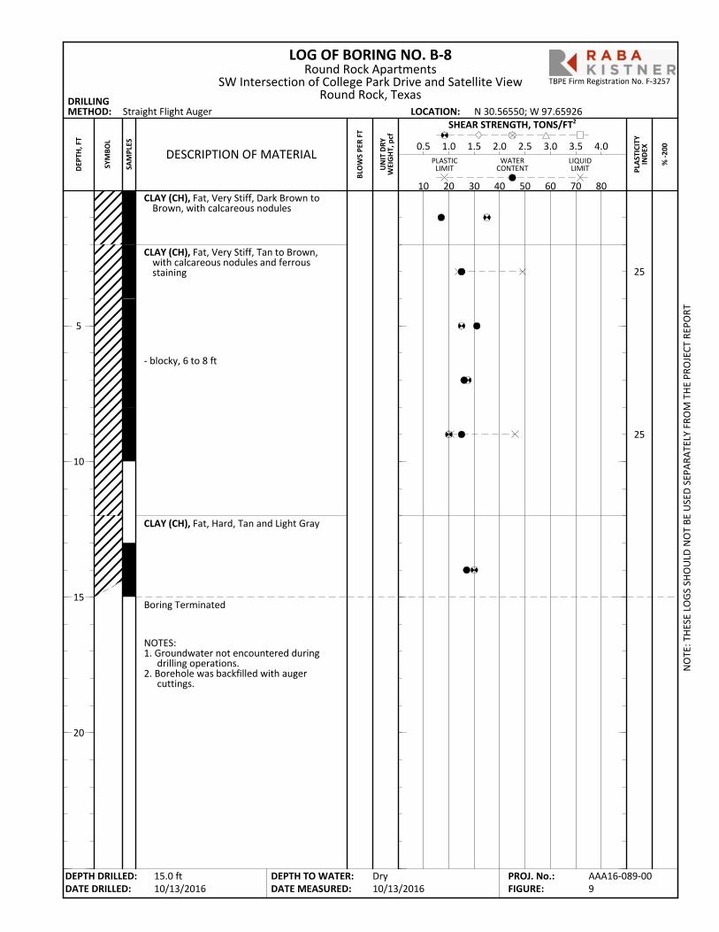
CLAY (CH), Fat, Very Stiff, Dark Brown toBrown, with calcareous nodules
CLAY (CH), Fat, Very Stiff, Tan to Brown,with calcareous nodules and ferrousstaining
- blocky, 6 to 8 ft
CLAY (CH), Fat, Hard, Tan and Light Gray
Boring Terminated
25
25
NOTES:1. Groundwater not encountered during
drilling operations.2. Borehole was backfilled with auger
cuttings.
LOG OF BORING NO. B-8
PLA
STIC
ITY
IND
EX
Straight Flight Auger
% -2
00
DRILLINGMETHOD: LOCATION:
PLASTICLIMIT
LIQUIDLIMIT
WATERCONTENT
BLO
WS
PER
FT
10 20 30 40 50 60 70 80
DESCRIPTION OF MATERIAL0.5 1.0 1.5 2.0 2.5 3.0 3.5 4.0
SHEAR STRENGTH, TONS/FT2
UN
IT D
RYW
EIG
HT,
pcf
N 30.56550; W 97.65926
NO
TE: T
HES
E LO
GS
SHO
ULD
NO
T BE
USE
D S
EPAR
ATEL
Y FR
OM
TH
E PR
OJE
CT R
EPO
RT
DEPTH DRILLED:DATE DRILLED:
DEPTH TO WATER:DATE MEASURED:
5
10
15
20
SYM
BOL
SAM
PLES
Round Rock ApartmentsSW Intersection of College Park Drive and Satellite View
Round Rock, Texas
Dry10/13/2016
DEP
TH, F
T
15.0 ft10/13/2016
AAA16-089-009
PROJ. No.:FIGURE:
TBPE Firm Registration No. F-3257
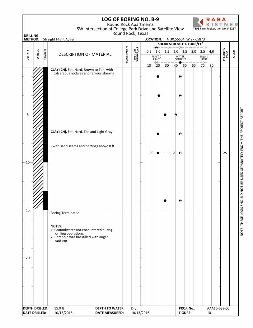
CLAY (CH), Fat, Hard, Brown to Tan, withcalcareous nodules and ferrous staining
CLAY (CH), Fat, Hard, Tan and Light Gray
- with sand seams and partings above 8 ft
Boring Terminated
25
NOTES:1. Groundwater not encountered during
drilling operations.2. Borehole was backfilled with auger
cuttings.
LOG OF BORING NO. B-9
PLA
STIC
ITY
IND
EX
Straight Flight Auger
% -2
00
DRILLINGMETHOD: LOCATION:
PLASTICLIMIT
LIQUIDLIMIT
WATERCONTENT
BLO
WS
PER
FT
10 20 30 40 50 60 70 80
DESCRIPTION OF MATERIAL0.5 1.0 1.5 2.0 2.5 3.0 3.5 4.0
SHEAR STRENGTH, TONS/FT2
UN
IT D
RYW
EIG
HT,
pcf
N 30.56604; W 97.65873
NO
TE: T
HES
E LO
GS
SHO
ULD
NO
T BE
USE
D S
EPAR
ATEL
Y FR
OM
TH
E PR
OJE
CT R
EPO
RT
DEPTH DRILLED:DATE DRILLED:
DEPTH TO WATER:DATE MEASURED:
5
10
15
20
SYM
BOL
SAM
PLES
Round Rock ApartmentsSW Intersection of College Park Drive and Satellite View
Round Rock, Texas
Dry10/13/2016
DEP
TH, F
T
15.0 ft10/13/2016
AAA16-089-0010
PROJ. No.:FIGURE:
TBPE Firm Registration No. F-3257
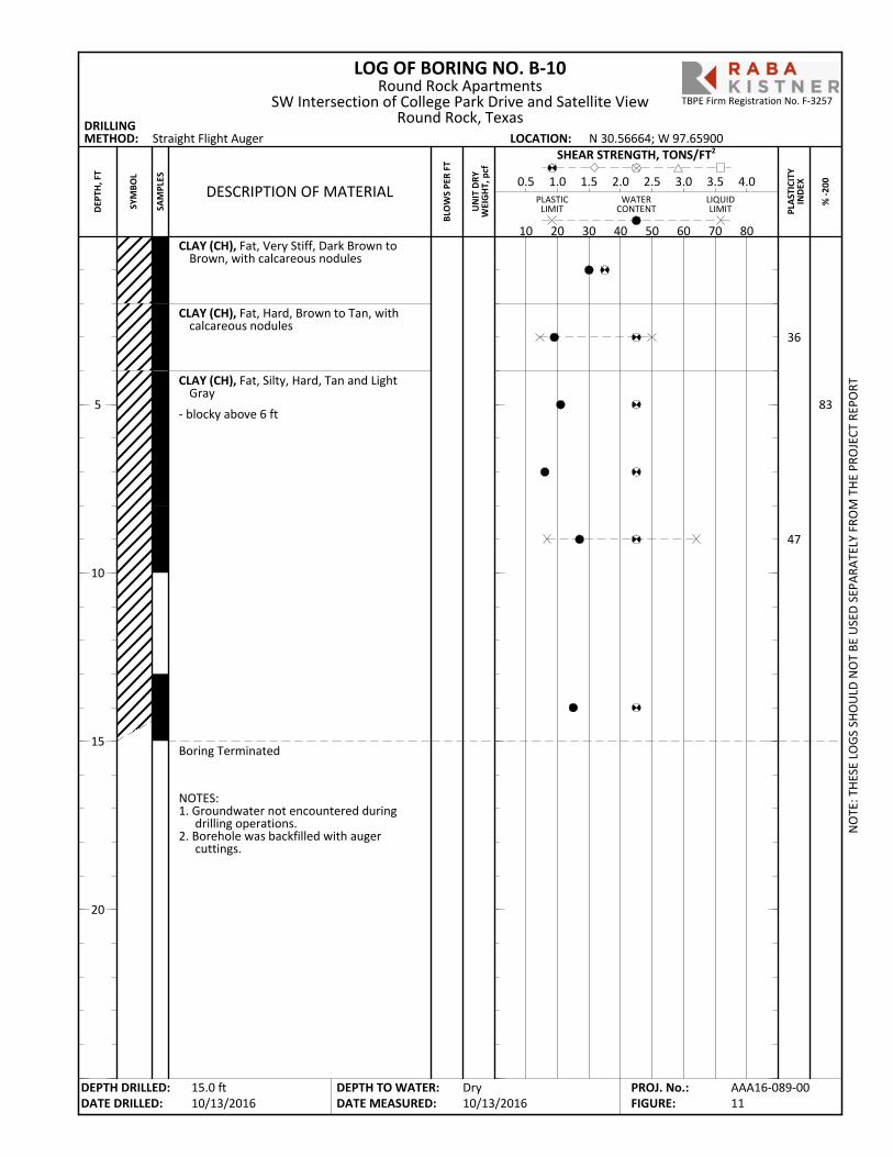
CLAY (CH), Fat, Very Stiff, Dark Brown toBrown, with calcareous nodules
CLAY (CH), Fat, Hard, Brown to Tan, withcalcareous nodules
CLAY (CH), Fat, Silty, Hard, Tan and LightGray
- blocky above 6 ft
Boring Terminated
36
47
NOTES:1. Groundwater not encountered during
drilling operations.2. Borehole was backfilled with auger
cuttings.
83
LOG OF BORING NO. B-10
PLA
STIC
ITY
IND
EX
Straight Flight Auger
% -2
00
DRILLINGMETHOD: LOCATION:
PLASTICLIMIT
LIQUIDLIMIT
WATERCONTENT
BLO
WS
PER
FT
10 20 30 40 50 60 70 80
DESCRIPTION OF MATERIAL0.5 1.0 1.5 2.0 2.5 3.0 3.5 4.0
SHEAR STRENGTH, TONS/FT2
UN
IT D
RYW
EIG
HT,
pcf
N 30.56664; W 97.65900
NO
TE: T
HES
E LO
GS
SHO
ULD
NO
T BE
USE
D S
EPAR
ATEL
Y FR
OM
TH
E PR
OJE
CT R
EPO
RT
DEPTH DRILLED:DATE DRILLED:
DEPTH TO WATER:DATE MEASURED:
5
10
15
20
SYM
BOL
SAM
PLES
Round Rock ApartmentsSW Intersection of College Park Drive and Satellite View
Round Rock, Texas
Dry10/13/2016
DEP
TH, F
T
15.0 ft10/13/2016
AAA16-089-0011
PROJ. No.:FIGURE:
TBPE Firm Registration No. F-3257
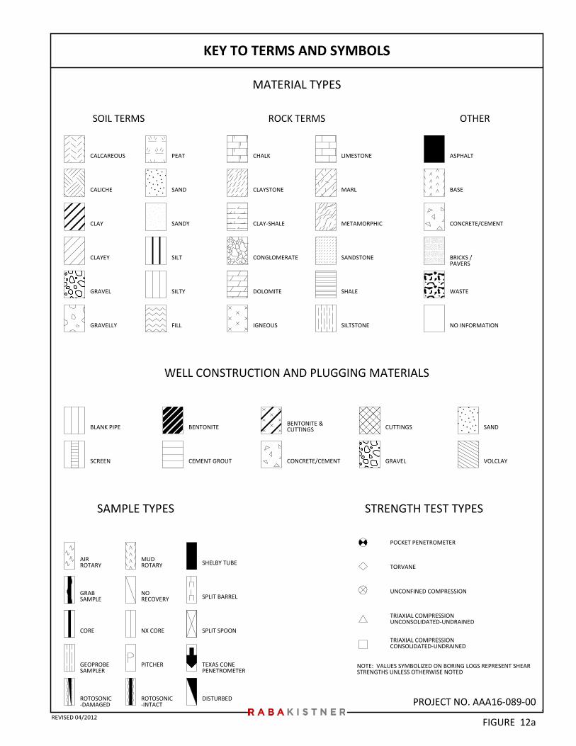
PROJECT NO. AAA16-089-00
CLAY-SHALE
SAMPLE TYPES
NO INFORMATION
BLANK PIPE
ASPHALT
IGNEOUS
LIMESTONE
FILL
GEOPROBESAMPLER
TEXAS CONEPENETROMETER
DISTURBED
METAMORPHIC
MARL
MUDROTARY
NORECOVERY SPLIT BARREL
SPLIT SPOONNX CORE
SHELBY TUBE
CALCAREOUS
CLAY
CLAYEY
GRAVEL
GRAVELLY
WELL CONSTRUCTION AND PLUGGING MATERIALS
SILTSTONE
CALICHE
CONGLOMERATE
AIRROTARY
GRABSAMPLE
DOLOMITE
BENTONITE
CORE
SOIL TERMS OTHER
NOTE: VALUES SYMBOLIZED ON BORING LOGS REPRESENT SHEARSTRENGTHS UNLESS OTHERWISE NOTED
BASE
KEY TO TERMS AND SYMBOLS
CUTTINGS
SAND
SANDY
SILT
SILTY
CHALK
STRENGTH TEST TYPES
CEMENT GROUT GRAVEL
SAND
POCKET PENETROMETER
TORVANE
UNCONFINED COMPRESSION
TRIAXIAL COMPRESSIONUNCONSOLIDATED-UNDRAINED
TRIAXIAL COMPRESSIONCONSOLIDATED-UNDRAINED
BRICKS /PAVERS
SCREEN
MATERIAL TYPES
VOLCLAY
SANDSTONE
SHALE
ROCK TERMS
WASTE
CONCRETE/CEMENT
PEAT
BENTONITE &CUTTINGS
CONCRETE/CEMENT
CLAYSTONE
ROTOSONIC-DAMAGED
ROTOSONIC-INTACT
PITCHER
FIGURE 12aREVISED 04/2012
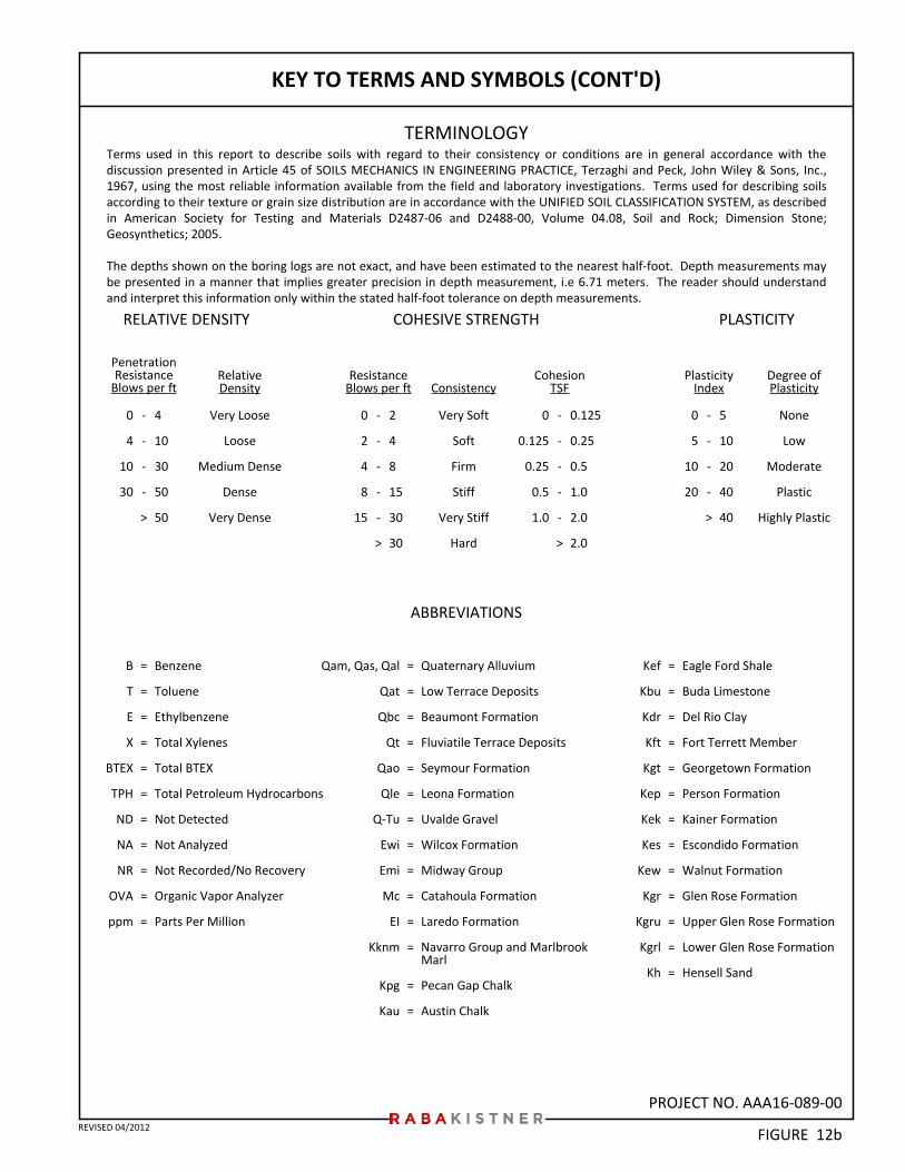
PROJECT NO. AAA16-089-00
KEY TO TERMS AND SYMBOLS (CONT'D)
TERMINOLOGY
RELATIVE DENSITY PLASTICITYCOHESIVE STRENGTH
PenetrationResistance
Blows per ftDegree ofPlasticity
PlasticityIndex
RelativeDensity
ResistanceBlows per ft
0
4
10
30
-
-
-
-
>
4
10
30
50
50
Very Loose
Loose
Medium Dense
Dense
Very Dense
ConsistencyCohesion
TSF
-
-
-
-
>
-
-
-
-
-
>
Benzene
Toluene
Ethylbenzene
Total Xylenes
Total BTEX
Total Petroleum Hydrocarbons
Not Detected
Not Analyzed
Not Recorded/No Recovery
Organic Vapor Analyzer
Parts Per Million
2
4
8
15
30
30
Very Soft
Soft
Firm
Stiff
Very Stiff
Hard
0
2
4
8
15
0
0.125
0.25
0.5
1.0
-
-
-
-
-
>
0.125
0.25
0.5
1.0
2.0
2.0
0
5
10
20
5
10
20
40
40
None
Low
Moderate
Plastic
Highly Plastic
=
=
=
=
=
=
=
=
=
=
=
ABBREVIATIONS
Qam, Qas, Qal
Qat
Qbc
Qt
Qao
Qle
Q-Tu
Ewi
Emi
Mc
EI
Kknm
Kpg
Kau
=
=
=
=
=
=
=
=
=
=
=
=
=
=
Kef
Kbu
Kdr
Kft
Kgt
Kep
Kek
Kes
Kew
Kgr
Kgru
Kgrl
Kh
Quaternary Alluvium
Low Terrace Deposits
Beaumont Formation
Fluviatile Terrace Deposits
Seymour Formation
Leona Formation
Uvalde Gravel
Wilcox Formation
Midway Group
Catahoula Formation
Laredo Formation
Navarro Group and MarlbrookMarl
Pecan Gap Chalk
Austin Chalk
=
=
=
=
=
=
=
=
=
=
=
=
=
Eagle Ford Shale
Buda Limestone
Del Rio Clay
Fort Terrett Member
Georgetown Formation
Person Formation
Kainer Formation
Escondido Formation
Walnut Formation
Glen Rose Formation
Upper Glen Rose Formation
Lower Glen Rose Formation
Hensell Sand
B
T
E
X
BTEX
TPH
ND
NA
NR
OVA
ppm
Terms used in this report to describe soils with regard to their consistency or conditions are in general accordance with thediscussion presented in Article 45 of SOILS MECHANICS IN ENGINEERING PRACTICE, Terzaghi and Peck, John Wiley & Sons, Inc.,1967, using the most reliable information available from the field and laboratory investigations. Terms used for describing soilsaccording to their texture or grain size distribution are in accordance with the UNIFIED SOIL CLASSIFICATION SYSTEM, as describedin American Society for Testing and Materials D2487-06 and D2488-00, Volume 04.08, Soil and Rock; Dimension Stone;Geosynthetics; 2005.
The depths shown on the boring logs are not exact, and have been estimated to the nearest half-foot. Depth measurements maybe presented in a manner that implies greater precision in depth measurement, i.e 6.71 meters. The reader should understandand interpret this information only within the stated half-foot tolerance on depth measurements.
FIGURE 12bREVISED 04/2012
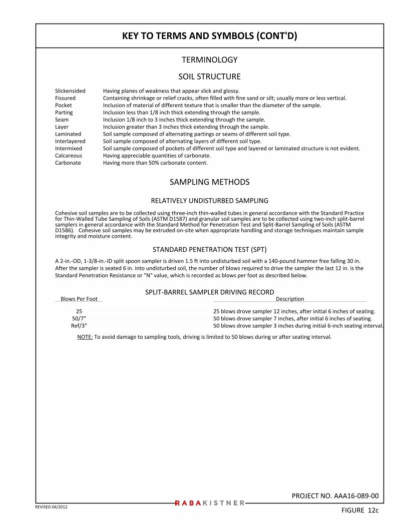
PROJECT NO. AAA16-089-00
KEY TO TERMS AND SYMBOLS (CONT'D)
TERMINOLOGY
SOIL STRUCTURE
SAMPLING METHODS
Having planes of weakness that appear slick and glossy.Containing shrinkage or relief cracks, often filled with fine sand or silt; usually more or less vertical.Inclusion of material of different texture that is smaller than the diameter of the sample.Inclusion less than 1/8 inch thick extending through the sample.Inclusion 1/8 inch to 3 inches thick extending through the sample.Inclusion greater than 3 inches thick extending through the sample.Soil sample composed of alternating partings or seams of different soil type.Soil sample composed of alternating layers of different soil type.Soil sample composed of pockets of different soil type and layered or laminated structure is not evident.Having appreciable quantities of carbonate.Having more than 50% carbonate content.
SlickensidedFissuredPocketPartingSeamLayerLaminatedInterlayeredIntermixedCalcareousCarbonate
RELATIVELY UNDISTURBED SAMPLING
NOTE: To avoid damage to sampling tools, driving is limited to 50 blows during or after seating interval.
STANDARD PENETRATION TEST (SPT)
Cohesive soil samples are to be collected using three-inch thin-walled tubes in general accordance with the Standard Practicefor Thin-Walled Tube Sampling of Soils (ASTM D1587) and granular soil samples are to be collected using two-inch split-barrelsamplers in general accordance with the Standard Method for Penetration Test and Split-Barrel Sampling of Soils (ASTMD1586). Cohesive soil samples may be extruded on-site when appropriate handling and storage techniques maintain sampleintegrity and moisture content.
Description
25 blows drove sampler 12 inches, after initial 6 inches of seating.50 blows drove sampler 7 inches, after initial 6 inches of seating.50 blows drove sampler 3 inches during initial 6-inch seating interval.
Blows Per Foot
2550/7"Ref/3"
FIGURE 12c
A 2-in.-OD, 1-3/8-in.-ID split spoon sampler is driven 1.5 ft into undisturbed soil with a 140-pound hammer free falling 30 in.After the sampler is seated 6 in. into undisturbed soil, the number of blows required to drive the sampler the last 12 in. is theStandard Penetration Resistance or "N" value, which is recorded as blows per foot as described below.
REVISED 04/2012
SPLIT-BARREL SAMPLER DRIVING RECORD
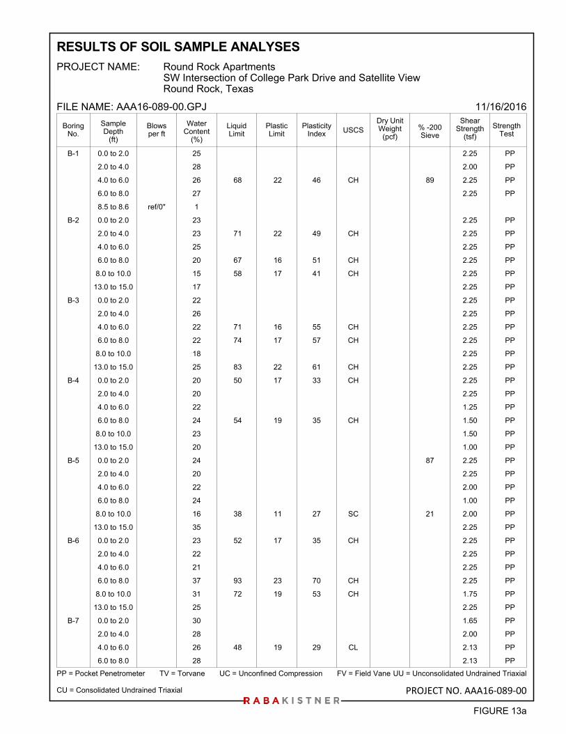
B-1 0.0 to 2.0 25 2.25 PP
2.0 to 4.0 28 2.00 PP
4.0 to 6.0 26 68 22 46 CH 89 2.25 PP
6.0 to 8.0 27 2.25 PP
8.5 to 8.6 ref/0" 1
B-2 0.0 to 2.0 23 2.25 PP
2.0 to 4.0 23 71 22 49 CH 2.25 PP
4.0 to 6.0 25 2.25 PP
6.0 to 8.0 20 67 16 51 CH 2.25 PP
8.0 to 10.0 15 58 17 41 CH 2.25 PP
13.0 to 15.0 17 2.25 PP
B-3 0.0 to 2.0 22 2.25 PP
2.0 to 4.0 26 2.25 PP
4.0 to 6.0 22 71 16 55 CH 2.25 PP
6.0 to 8.0 22 74 17 57 CH 2.25 PP
8.0 to 10.0 18 2.25 PP
13.0 to 15.0 25 83 22 61 CH 2.25 PP
B-4 0.0 to 2.0 20 50 17 33 CH 2.25 PP
2.0 to 4.0 20 2.25 PP
4.0 to 6.0 22 1.25 PP
6.0 to 8.0 24 54 19 35 CH 1.50 PP
8.0 to 10.0 23 1.50 PP
13.0 to 15.0 20 1.00 PP
B-5 0.0 to 2.0 24 87 2.25 PP
2.0 to 4.0 20 2.25 PP
4.0 to 6.0 22 2.00 PP
6.0 to 8.0 24 1.00 PP
8.0 to 10.0 16 38 11 27 SC 21 2.00 PP
13.0 to 15.0 35 2.25 PP
B-6 0.0 to 2.0 23 52 17 35 CH 2.25 PP
2.0 to 4.0 22 2.25 PP
4.0 to 6.0 21 2.25 PP
6.0 to 8.0 37 93 23 70 CH 2.25 PP
8.0 to 10.0 31 72 19 53 CH 1.75 PP
13.0 to 15.0 25 2.25 PP
B-7 0.0 to 2.0 30 1.65 PP
2.0 to 4.0 28 2.00 PP
4.0 to 6.0 26 48 19 29 CL 2.13 PP
6.0 to 8.0 28 2.13 PP
PlasticityIndex
LiquidLimit
PP = Pocket Penetrometer TV = Torvane UC = Unconfined Compression FV = Field Vane
PlasticLimit
WaterContent
(%)
Dry UnitWeight
(pcf)
PROJECT NAME:
FILE NAME: AAA16-089-00.GPJ
USCS % -200Sieve
ShearStrength
(tsf)
StrengthTest
BoringNo.
11/16/2016
UU = Unconsolidated Undrained Triaxial
SampleDepth
(ft)
CU = Consolidated Undrained Triaxial
Round Rock ApartmentsSW Intersection of College Park Drive and Satellite ViewRound Rock, Texas
RESULTS OF SOIL SAMPLE ANALYSES
Blowsper ft
FIGURE 13a
PROJECT NO. AAA16-089-00
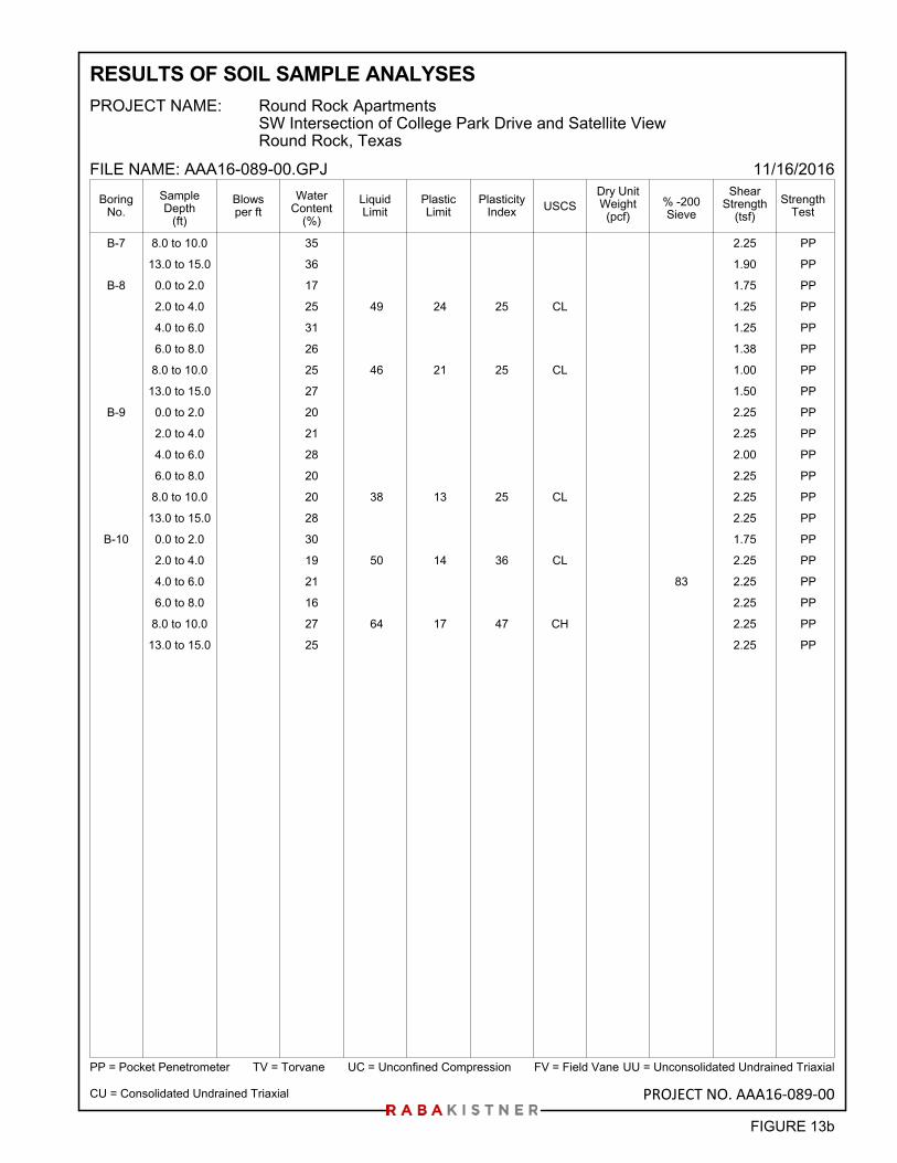
B-7 8.0 to 10.0 35 2.25 PP
13.0 to 15.0 36 1.90 PP
B-8 0.0 to 2.0 17 1.75 PP
2.0 to 4.0 25 49 24 25 CL 1.25 PP
4.0 to 6.0 31 1.25 PP
6.0 to 8.0 26 1.38 PP
8.0 to 10.0 25 46 21 25 CL 1.00 PP
13.0 to 15.0 27 1.50 PP
B-9 0.0 to 2.0 20 2.25 PP
2.0 to 4.0 21 2.25 PP
4.0 to 6.0 28 2.00 PP
6.0 to 8.0 20 2.25 PP
8.0 to 10.0 20 38 13 25 CL 2.25 PP
13.0 to 15.0 28 2.25 PP
B-10 0.0 to 2.0 30 1.75 PP
2.0 to 4.0 19 50 14 36 CL 2.25 PP
4.0 to 6.0 21 83 2.25 PP
6.0 to 8.0 16 2.25 PP
8.0 to 10.0 27 64 17 47 CH 2.25 PP
13.0 to 15.0 25 2.25 PP
PlasticityIndex
LiquidLimit
PP = Pocket Penetrometer TV = Torvane UC = Unconfined Compression FV = Field Vane
PlasticLimit
WaterContent
(%)
Dry UnitWeight
(pcf)
PROJECT NAME:
FILE NAME: AAA16-089-00.GPJ
USCS % -200Sieve
ShearStrength
(tsf)
StrengthTest
BoringNo.
11/16/2016
UU = Unconsolidated Undrained Triaxial
SampleDepth
(ft)
CU = Consolidated Undrained Triaxial
Round Rock ApartmentsSW Intersection of College Park Drive and Satellite ViewRound Rock, Texas
RESULTS OF SOIL SAMPLE ANALYSES
Blowsper ft
FIGURE 13b
PROJECT NO. AAA16-089-00
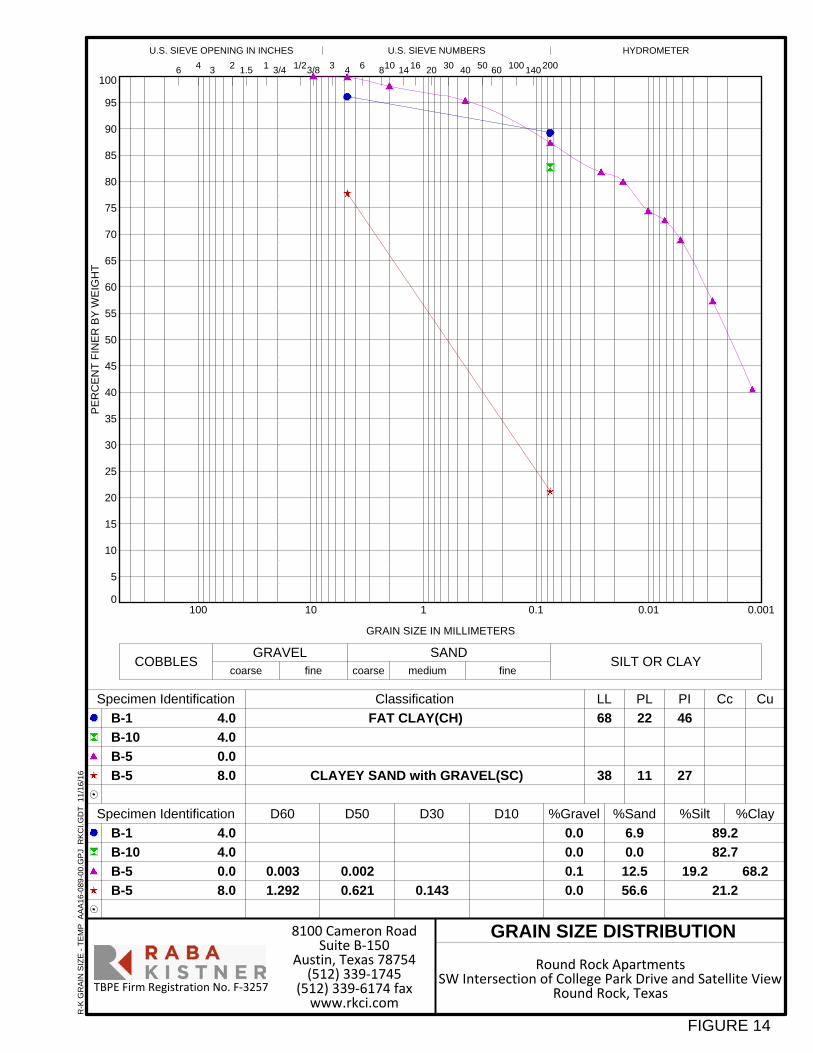
0
5
10
15
20
25
30
35
40
45
50
55
60
65
70
75
80
85
90
95
100
0.0010.010.1110100
46
27
FAT CLAY(CH)
CLAYEY SAND with GRAVEL(SC)
fine
HYDROMETERU.S. SIEVE OPENING IN INCHES U.S. SIEVE NUMBERS
30 40 501.5
GRAIN SIZE IN MILLIMETERS
41 3/4
68
38
89.2
82.7
21.2
D10 %Gravel %Sand
2006 810 14
D30
1/23/8 3
PE
RC
EN
T F
INE
R B
Y W
EIG
HT
coarse fine coarse medium
6
0.0
0.0
0.1
0.0
Classification
6.9
0.0
12.5
56.6
19.2
CuPI CcLL PL
6016 20
D50
0.002
0.621 0.143
100 1403 2
COBBLESGRAVEL SAND
SILT OR CLAY
4
68.2
4.0
4.0
0.0
8.0
Specimen Identification
Specimen Identification
4.0
4.0
0.0
8.0
%Silt %Clay
B-1
B-10
B-5
B-5
B-1
B-10
B-5
B-5
GRAIN SIZE DISTRIBUTION
22
11
D60
0.003
1.292
TBPE Firm Registration No. F‐3257
Round Rock ApartmentsSW Intersection of College Park Drive and Satellite View
Round Rock, Texas
8100 Cameron RoadSuite B‐150
Austin, Texas 78754(512) 339‐1745
(512) 339‐6174 faxwww.rkci.com
R-K
GR
AIN
SIZ
E -
TE
MP
A
AA
16-0
89-0
0.G
PJ
RK
CI.
GD
T
11/1
6/16
FIGURE 14
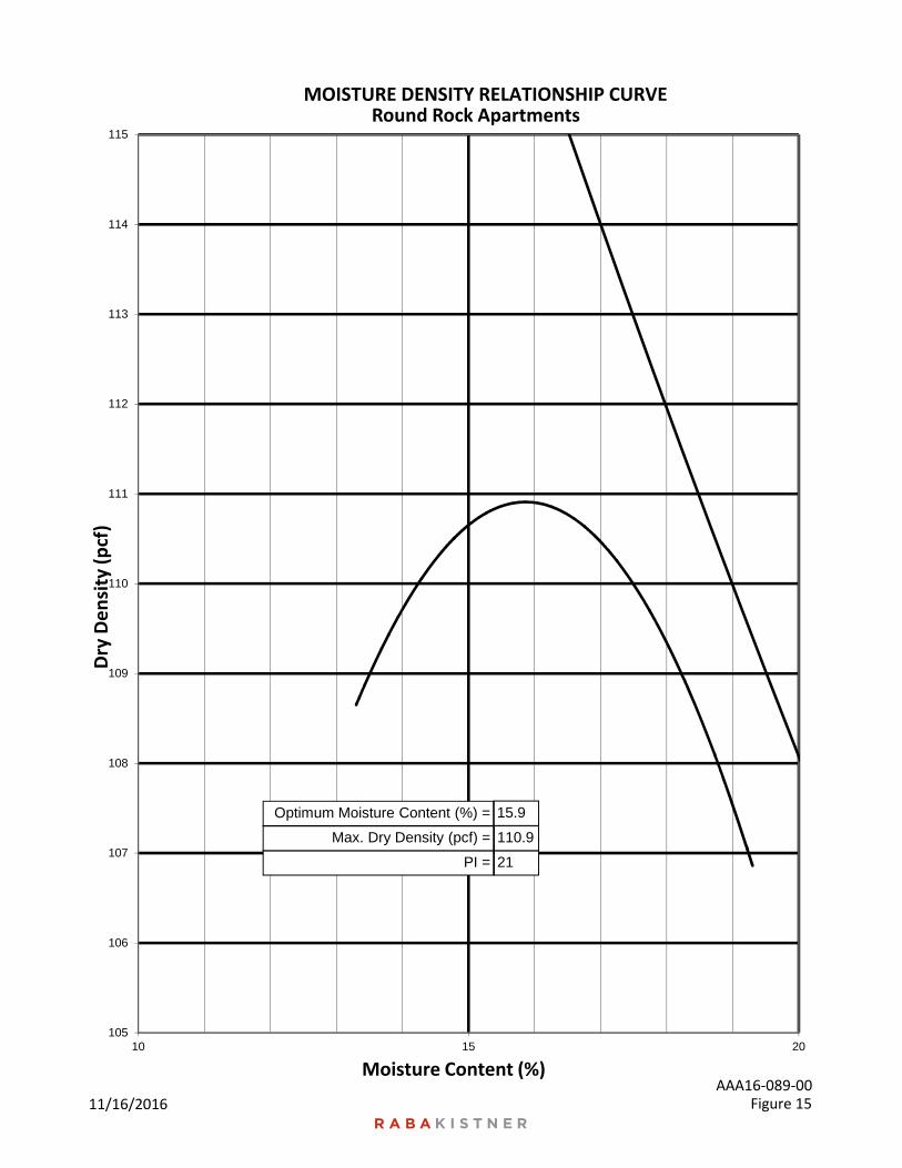
105
106
107
108
109
110
111
112
113
114
115
10 15 20
Dry Density (pcf)
Moisture Content (%)
Round Rock ApartmentsMOISTURE DENSITY RELATIONSHIP CURVE
PI = 21
Max. Dry Density (pcf) = 110.9
Optimum Moisture Content (%) = 15.9
11/16/2016 Figure 15AAA16‐089‐00
Geotechnical-Engineering Report
Geotechnical Services Are Performed for Specific Purposes, Persons, and ProjectsGeotechnical engineers structure their services to meet the specific needs of their clients. A geotechnical-engineering study conducted for a civil engineer may not fulfill the needs of a constructor — a construction contractor — or even another civil engineer. Because each geotechnical- engineering study is unique, each geotechnical-engineering report is unique, prepared solely for the client. No one except you should rely on this geotechnical-engineering report without first conferring with the geotechnical engineer who prepared it. And no one — not even you — should apply this report for any purpose or project except the one originally contemplated.
Read the Full ReportSerious problems have occurred because those relying on a geotechnical-engineering report did not read it all. Do not rely on an executive summary. Do not read selected elements only.
Geotechnical Engineers Base Each Report on a Unique Set of Project-Specific FactorsGeotechnical engineers consider many unique, project-specific factors when establishing the scope of a study. Typical factors include: the client’s goals, objectives, and risk-management preferences; the general nature of the structure involved, its size, and configuration; the location of the structure on the site; and other planned or existing site improvements, such as access roads, parking lots, and underground utilities. Unless the geotechnical engineer who conducted the study specifically indicates otherwise, do not rely on a geotechnical-engineering report that was:• not prepared for you;• not prepared for your project;• not prepared for the specific site explored; or• completed before important project changes were made.
Typical changes that can erode the reliability of an existing geotechnical-engineering report include those that affect: • the function of the proposed structure, as when it’s changed
from a parking garage to an office building, or from a light-industrial plant to a refrigerated warehouse;
• the elevation, configuration, location, orientation, or weight of the proposed structure;
• the composition of the design team; or• project ownership.
As a general rule, always inform your geotechnical engineer of project changes—even minor ones—and request an
assessment of their impact. Geotechnical engineers cannot accept responsibility or liability for problems that occur because their reports do not consider developments of which they were not informed.
Subsurface Conditions Can ChangeA geotechnical-engineering report is based on conditions that existed at the time the geotechnical engineer performed the study. Do not rely on a geotechnical-engineering report whose adequacy may have been affected by: the passage of time; man-made events, such as construction on or adjacent to the site; or natural events, such as floods, droughts, earthquakes, or groundwater fluctuations. Contact the geotechnical engineer before applying this report to determine if it is still reliable. A minor amount of additional testing or analysis could prevent major problems.
Most Geotechnical Findings Are Professional OpinionsSite exploration identifies subsurface conditions only at those points where subsurface tests are conducted or samples are taken. Geotechnical engineers review field and laboratory data and then apply their professional judgment to render an opinion about subsurface conditions throughout the site. Actual subsurface conditions may differ — sometimes significantly — from those indicated in your report. Retaining the geotechnical engineer who developed your report to provide geotechnical-construction observation is the most effective method of managing the risks associated with unanticipated conditions.
A Report’s Recommendations Are Not FinalDo not overrely on the confirmation-dependent recommendations included in your report. Confirmation-dependent recommendations are not final, because geotechnical engineers develop them principally from judgment and opinion. Geotechnical engineers can finalize their recommendations only by observing actual subsurface conditions revealed during construction. The geotechnical engineer who developed your report cannot assume responsibility or liability for the report’s confirmation-dependent recommendations if that engineer does not perform the geotechnical-construction observation required to confirm the recommendations’ applicability.
A Geotechnical-Engineering Report Is Subject to MisinterpretationOther design-team members’ misinterpretation of geotechnical-engineering reports has resulted in costly
Important Information about This
Subsurface problems are a principal cause of construction delays, cost overruns, claims, and disputes.
While you cannot eliminate all such risks, you can manage them. The following information is provided to help.
problems. Confront that risk by having your geo technical engineer confer with appropriate members of the design team after submitting the report. Also retain your geotechnical engineer to review pertinent elements of the design team’s plans and specifications. Constructors can also misinterpret a geotechnical-engineering report. Confront that risk by having your geotechnical engineer participate in prebid and preconstruction conferences, and by providing geotechnical construction observation.
Do Not Redraw the Engineer’s LogsGeotechnical engineers prepare final boring and testing logs based upon their interpretation of field logs and laboratory data. To prevent errors or omissions, the logs included in a geotechnical-engineering report should never be redrawn for inclusion in architectural or other design drawings. Only photographic or electronic reproduction is acceptable, but recognize that separating logs from the report can elevate risk.
Give Constructors a Complete Report and GuidanceSome owners and design professionals mistakenly believe they can make constructors liable for unanticipated subsurface conditions by limiting what they provide for bid preparation. To help prevent costly problems, give constructors the complete geotechnical-engineering report, but preface it with a clearly written letter of transmittal. In that letter, advise constructors that the report was not prepared for purposes of bid development and that the report’s accuracy is limited; encourage them to confer with the geotechnical engineer who prepared the report (a modest fee may be required) and/or to conduct additional study to obtain the specific types of information they need or prefer. A prebid conference can also be valuable. Be sure constructors have sufficient time to perform additional study. Only then might you be in a position to give constructors the best information available to you, while requiring them to at least share some of the financial responsibilities stemming from unanticipated conditions.
Read Responsibility Provisions CloselySome clients, design professionals, and constructors fail to recognize that geotechnical engineering is far less exact than other engineering disciplines. This lack of understanding has created unrealistic expectations that have led to disappointments, claims, and disputes. To help reduce the risk of such outcomes, geotechnical engineers commonly include a variety of explanatory provisions in their reports. Sometimes labeled “limitations,” many of these provisions indicate where geotechnical engineers’ responsibilities begin and end, to help
others recognize their own responsibilities and risks. Read these provisions closely. Ask questions. Your geotechnical engineer should respond fully and frankly.
Environmental Concerns Are Not Covered The equipment, techniques, and personnel used to perform an environmental study differ significantly from those used to perform a geotechnical study. For that reason, a geotechnical-engineering report does not usually relate any environmental findings, conclusions, or recommendations; e.g., about the likelihood of encountering underground storage tanks or regulated contaminants. Unanticipated environmental problems have led to numerous project failures. If you have not yet obtained your own environmental information, ask your geotechnical consultant for risk-management guidance. Do not rely on an environmental report prepared for someone else.
Obtain Professional Assistance To Deal with MoldDiverse strategies can be applied during building design, construction, operation, and maintenance to prevent significant amounts of mold from growing on indoor surfaces. To be effective, all such strategies should be devised for the express purpose of mold prevention, integrated into a comprehensive plan, and executed with diligent oversight by a professional mold-prevention consultant. Because just a small amount of water or moisture can lead to the development of severe mold infestations, many mold- prevention strategies focus on keeping building surfaces dry. While groundwater, water infiltration, and similar issues may have been addressed as part of the geotechnical- engineering study whose findings are conveyed in this report, the geotechnical engineer in charge of this project is not a mold prevention consultant; none of the services performed in connection with the geotechnical engineer’s study were designed or conducted for the purpose of mold prevention. Proper implementation of the recommendations conveyed in this report will not of itself be sufficient to prevent mold from growing in or on the structure involved.
Rely, on Your GBC-Member Geotechnical Engineer for Additional AssistanceMembership in the Geotechnical Business Council of the Geoprofessional Business Association exposes geotechnical engineers to a wide array of risk-confrontation techniques that can be of genuine benefit for everyone involved with a construction project. Confer with you GBC-Member geotechnical engineer for more information.
8811 Colesville Road/Suite G106, Silver Spring, MD 20910Telephone: 301/565-2733 Facsimile: 301/589-2017
e-mail: [email protected] www.geoprofessional.org
Copyright 2015 by Geoprofessional Business Association (GBA). Duplication, reproduction, or copying of this document, or its contents, in whole or in part, by any means whatsoever, is strictly prohibited, except with GBA’s specific written permission. Excerpting, quoting, or otherwise extracting wording from this document
is permitted only with the express written permission of GBA, and only for purposes of scholarly research or book review. Only members of GBA may use this document as a complement to or as an element of a geotechnical-engineering report. Any other firm, individual, or other entity that so uses this document without
being a GBA member could be commiting negligent or intentional (fraudulent) misrepresentation.
ENGINEERING • ENVIRONMENTAL • INFRASTRUCTURE • PROJECT CONTROL
Austin, TX
Brownsville, TX
Dallas, TX
Freeport, TX
San Antonio, TX
Houston, TX
McAllen, TX
New Braunfels, TX
Lake Worth, FL
Lincoln, NE
Salt Lake City, UT
Mexico
RABA KISTNER