Embed Size (px)
Citation preview
geotechnics construction materials testing
90 scarsdale road telephone: (905) 474-5265
toronto, ontario fax: (416) 444-3179
M3B 2R7 e-mail: [email protected]
Report Ref. No. 17-069
April 2019
Prepared For:
10046043 Canada Inc.
898 Parkland Avenue
Mississauga, ON
L5H 3H1
Prepared By:
Alston Associates
A division of Terrapex Environmental Ltd.
Distribution:
Digital Copy - 10046043 Canada Inc.
GEOTECHNICAL INVESTIGATION AND SLOPE
STABILITY ASSESSMENT
PROPOSED RESIDENTIAL DEVELOPMENT
1950 AND 1952 FAIRPORT ROAD
PICKERING, ONTARIO
alston associates Reference 17-069
A division of Terrapex Environmental Ltd. April 2019
GEOTECHNICAL INVESTIGATION REPORT
1950 AND 1952 FAIRPORT ROAD, PICKERING, ONTARIO
10046043 CANADA INC.
i
CONTENTS
1 INTRODUCTION .................................................................................................................................. 1
2 FIELDWORK ......................................................................................................................................... 1
3 LABORATORY TESTS ............................................................................................................................ 2
4 SITE AND SUBSURFACE CONDITIONS ............................................................................................... 2
4.1 Site Description ...................................................................................................................................... 3
4.2 Topsoil ..................................................................................................................................................... 3
4.3 Fill Material ............................................................................................................................................. 3
4.4 Peat ......................................................................................................................................................... 3
4.5 Native Soils ............................................................................................................................................. 4
4.5.1 Silt ............................................................................................................................................... 4
4.5.2 Fine Sand .................................................................................................................................. 4
4.5.3 Silty Clay .................................................................................................................................... 5
4.5.4 Sandy Silty Clay (Till) ................................................................................................................. 5
4.6 Groundwater .......................................................................................................................................... 5
5 DISCUSSION AND RECOMMENDATIONS ......................................................................................... 7
5.1 Excavation.............................................................................................................................................. 7
5.2 Groundwater Control ............................................................................................................................ 8
5.3 Reuse of On-site Excavated Soil as a Compacted Backfill .............................................................. 8
5.4 Engineered Fill ........................................................................................................................................ 9
5.5 Service Trenches .................................................................................................................................. 10
5.6 Foundation Design ............................................................................................................................... 11
5.7 Basement Floors ................................................................................................................................... 12
5.8 Pavement Design ................................................................................................................................ 13
5.9 Earthquake Design Parameters ......................................................................................................... 14
5.10 Lateral Earth Pressure .......................................................................................................................... 14
5.11 Chemical Characterization of Subsurface Soil................................................................................. 16
6 STABILITY ASSESSMENT OF CREEK BANK ........................................................................................ 16
6.1 Stable Slope Allowance ...................................................................................................................... 17
6.2 Toe Erosion Allowance ........................................................................................................................ 18
6.3 Erosion Access Allowance ................................................................................................................. 18
6.4 Conclusion ............................................................................................................................................ 18
7 LIMITATIONS OF REPORT .................................................................................................................. 19
alston associates Reference 17-069
A division of Terrapex Environmental Ltd. April 2019
GEOTECHNICAL INVESTIGATION REPORT
1950 AND 1952 FAIRPORT ROAD, PICKERING, ONTARIO
10046043 CANADA INC.
ii
APPENDICES .
APPENDIX A LIMITATIONS OF REPORT
APPENDIX B FIGURE 1 - BOREHOLE LOCATION PLAN
FIGURE 2 – DEPTH OF FILL
APPENDIX C BOREHOLE LOG SHEETS
TEST PIT LOG SHEETS
APPENDIX D LABORATORY TEST RESULTS
APPENDIX E TYPICAL PERIMETER AND UNDERFLOOR DRAINAGE SYSTEM
APPENDIX F CERTIFICATE OF CHEMICAL ANALYSES
APPENDIX G SLOPE STABILITY ANALYSIS CROSS SECTIONS
alston associates Reference 17-069
A division of Terrapex Environmental Ltd. April 2019
GEOTECHNICAL INVESTIGATION REPORT
1950 AND 1952 FAIRPORT ROAD, PICKERING, ONTARIO
10046043 CANADA INC.
1
1 INTRODUCTION
Alston Associates (AA) has been retained by 10046043 Canada Inc. to carry out a geotechnical investigation
and slope stability assessment for a proposed residential development located at 1950 and 1952 Fairport
Road in Pickering, Ontario (the Site). Authorization to proceed with this study was given by Mr. Yecheng Li of
10046043 Canada Inc.
We understand that it is proposed to redevelop the Site with a low-rise residential subdivision consisting of 30
single family homes with basement construction serviced with a new municipal road and underground water,
sanitary, and storm services.
A grading plan was not available at the time of the investigation, and accordingly the recommendations
provided in this report are considered to be preliminary in nature, subject for review and revision upon
completion of proposed grading plans.
The purpose of this investigation was to characterize the subsurface soil and groundwater conditions, to
determine the engineering properties of the various soil deposits underlying the site, and to provide
preliminary geotechnical engineering recommendations pertaining to the proposed development.
This report presents the results of the investigation performed in accordance with the general terms of
reference outlined above and is intended for the guidance of the client and the design architects or
engineers only. It is assumed that the design will be in accordance with the applicable building codes and
standards.
2 FIELDWORK
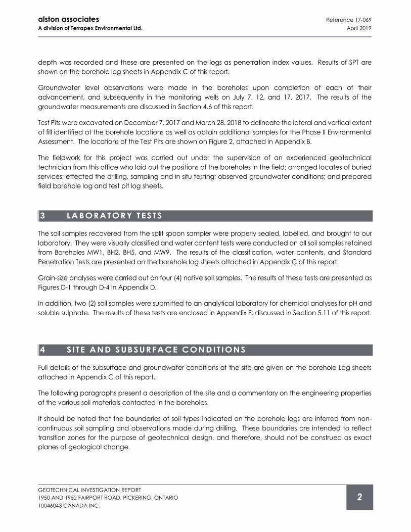
The fieldwork for this investigation was carried out from June 26 to 28, 2017. It consisted of eleven (11)
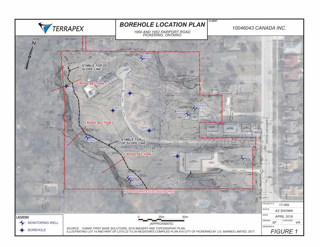
boreholes, advanced by a drilling contractor commissioned by AA. The locations of the boreholes were
chosen by AA to provide general coverage of the site for the proposed development, and are shown on the
Borehole Location Plan enclosed in Appendix B. The fieldwork was carried out in conjunction with the Phase
II Environmental Assessment and Hydrogeological study undertaken by Terrapex Environmental Ltd.
(Terrapex).
The boreholes were advanced to depths ranging from 4.3 to 8.2 m below ground surface (mbgs). Seven (7)
of the boreholes (Boreholes MW1, MW4A, MW4B, MW6, MW8A, MW8B, and MW9) were instrumented with
monitoring wells, to determine the long-term groundwater table at the site and permit sampling of the
groundwater for chemical analyses and hydrogeological assessment to be undertaken by Terrapex.
The ground surface elevations at the borehole locations were established by J.D. Barnes Limited; shown on
their Topographic Survey Plan dated August 11, 2017.
Standard penetration tests were carried out in the course of advancing the boreholes to take representative
soil samples and to measure penetration index values (N-values) to characterize the condition of the various
soil materials. The number of blows of the striking hammer required to drive the split spoon sampler to 300 mm
alston associates Reference 17-069
A division of Terrapex Environmental Ltd. April 2019
GEOTECHNICAL INVESTIGATION REPORT
1950 AND 1952 FAIRPORT ROAD, PICKERING, ONTARIO
10046043 CANADA INC.
2
depth was recorded and these are presented on the logs as penetration index values. Results of SPT are
shown on the borehole log sheets in Appendix C of this report.
Groundwater level observations were made in the boreholes upon completion of each of their
advancement, and subsequently in the monitoring wells on July 7, 12, and 17, 2017. The results of the
groundwater measurements are discussed in Section 4.6 of this report.
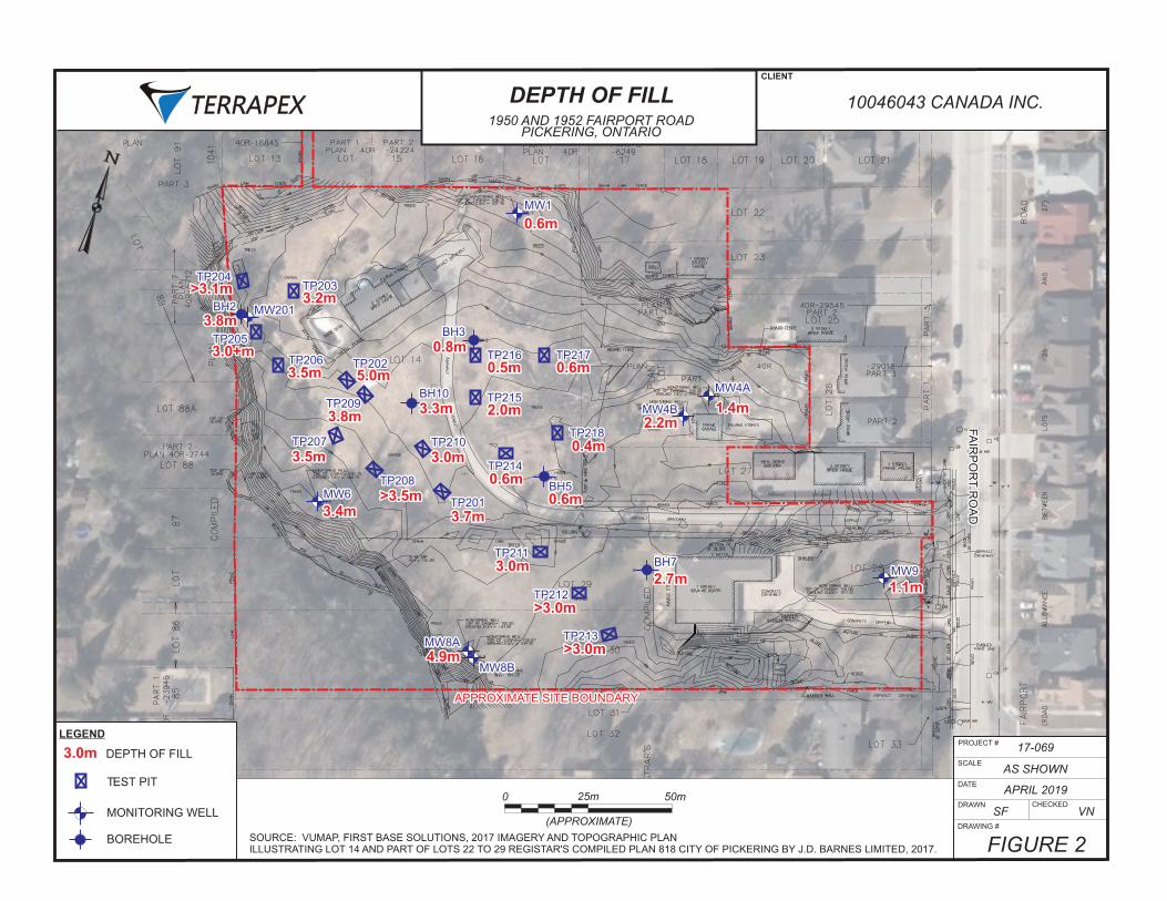
Test Pits were excavated on December 7, 2017 and March 28, 2018 to delineate the lateral and vertical extent
of fill identified at the borehole locations as well as obtain additional samples for the Phase II Environmental
Assessment. The locations of the Test Pits are shown on Figure 2, attached in Appendix B.
The fieldwork for this project was carried out under the supervision of an experienced geotechnical
technician from this office who laid out the positions of the boreholes in the field; arranged locates of buried
services; effected the drilling, sampling and in situ testing; observed groundwater conditions; and prepared
field borehole log and test pit log sheets.
3 LABORATORY TESTS
The soil samples recovered from the split spoon sampler were properly sealed, labelled, and brought to our
laboratory. They were visually classified and water content tests were conducted on all soil samples retained
from Boreholes MW1, BH2, BH5, and MW9. The results of the classification, water contents, and Standard
Penetration Tests are presented on the borehole log sheets attached in Appendix C of this report.
Grain-size analyses were carried out on four (4) native soil samples. The results of these tests are presented as
Figures D-1 through D-4 in Appendix D.
In addition, two (2) soil samples were submitted to an analytical laboratory for chemical analyses for pH and
soluble sulphate. The results of these tests are enclosed in Appendix F; discussed in Section 5.11 of this report.
4 SI TE AND SUBSURFACE CONDIT IONS
Full details of the subsurface and groundwater conditions at the site are given on the borehole Log sheets
attached in Appendix C of this report.
The following paragraphs present a description of the site and a commentary on the engineering properties
of the various soil materials contacted in the boreholes.
It should be noted that the boundaries of soil types indicated on the borehole logs are inferred from non-
continuous soil sampling and observations made during drilling. These boundaries are intended to reflect
transition zones for the purpose of geotechnical design, and therefore, should not be construed as exact
planes of geological change.
alston associates Reference 17-069
A division of Terrapex Environmental Ltd. April 2019
GEOTECHNICAL INVESTIGATION REPORT
1950 AND 1952 FAIRPORT ROAD, PICKERING, ONTARIO
10046043 CANADA INC.
3
4 .1 Site Descript ion
The site consists of the properties with the municipal addresses 1950 and 1952 Fairport Road, and the rear
portions of the properties 1954 and 1966 Fairport Road, in Pickering, Ontario. It is bounded by residential
properties on all sides. It has an irregular shape; approximately 150 m wide and 100 to 200 m long.
The site is developed with two residential houses located at the southeast and northwest corners. The
remaining area of the site is vacant and covered with vegetation and some trees. The Dunbarton Creek runs
in a north-south direction along the western limit of the site.
The majority of the ground surface topography of the site is slightly undulating. The ground surface elevations
established at the borehole locations range from 104.7 to 107.4 m.
4 .2 Topsoi l
Topsoil is present in Borehole BH5 and several of the Test Pits. The thickness of the topsoil ranged from 50 mm
to 400 mm.
It should be noted that thicker topsoil than found in the borehole and test pits may be present in other places.
4 .3 Fi l l Material
Fill material is present in all the boreholes at the ground surface and below the surficial topsoil and in all test
pits excavated at the site. The fill consists of variable sandy silt, silty sand, silty clay, sandy silty clay, and sandy
clayey soils with trace to some gravel. Locally, it also contains construction debris such as asphalt, concrete,
roofing material, saw dust, rebar and welded wire mesh, wood, topsoil pockets, and other organic material.
The fill layer across the tableland extends from 0.4 to 2.2 mbgs. A greater fill thickness is present in the vicinity
of Dunbarton Creek at Boreholes BH2, MW6, MW8A, and BH10, and in majority of the test pits ranging from
2.5 to 4.0 mbgs. Large tree trunks were encountered in several of the test pits. Due to influx of groundwater
in Test Pits 212 and 213, the thickness of the fill could not be determined as the walls of the test pits caved in
with the incoming water and the test pits could not be extended deeper.
The fill is brown, dark brown, dark grey, and black in color and damp to moist in appearance.
SPT carried out in the fill material measured N-values ranging from 3 to 29; indicating a very loose or soft to
firm consistency/compact compactness condition.
The thickness of the fill measured at the borehole and test pit locations is shown on Figure 2.
4 .4 Peat
A layer of peat is present in Borehole BH10 and Test Pit 209, underlying the fill. It has a thickness of
approximately 300 mm. It is black in colour and wet in appearance.
alston associates Reference 17-069
A division of Terrapex Environmental Ltd. April 2019
GEOTECHNICAL INVESTIGATION REPORT
1950 AND 1952 FAIRPORT ROAD, PICKERING, ONTARIO
10046043 CANADA INC.
4
4 .5 Native Soi ls
The soil stratum below the fill material is the native soil consisting of silt, fine sand, silty clay, and sandy silty clay
(till) soils.
4 .5 .1 Sil t
A deposit of silt with some fine sand and trace clay is present below the fill material in Boreholes MW1, BH3,
MW4A, MW4B, BH5, BH7, MW8A, and MW9 and below the fine sand layer in Borehole BH10. It extends to an
approximate depth of 6.8 mbgs at Borehole MW8A and to the explored depths of the remaining boreholes.
The silt unit changes from brown to grey in color at depths ranging from 0.9 to 3.7 mbgs and has a damp to
wet appearance. The water content of the silt in Boreholes MW1, BH5, and MW9 ranges from 11 to 21% by
weight.
SPT carried out in the silt unit has N-values ranging from 4 to 96, indicating a loose to very dense compactness
condition; loose to compact in Borehole BH7, dense to very dense in the remaining boreholes.
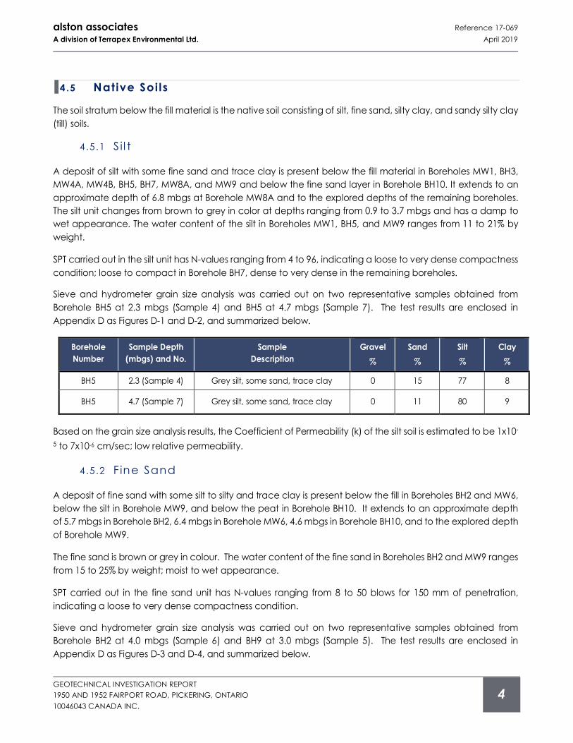
Sieve and hydrometer grain size analysis was carried out on two representative samples obtained from
Borehole BH5 at 2.3 mbgs (Sample 4) and BH5 at 4.7 mbgs (Sample 7). The test results are enclosed in
Appendix D as Figures D-1 and D-2, and summarized below.
Borehole
Number
Sample Depth
(mbgs) and No.
Sample
Description
Gravel
%
Sand
%
Silt
%
Clay
%
BH5 2.3 (Sample 4) Grey silt, some sand, trace clay 0 15 77 8
BH5 4.7 (Sample 7) Grey silt, some sand, trace clay 0 11 80 9
Based on the grain size analysis results, the Coefficient of Permeability (k) of the silt soil is estimated to be 1x10-
5 to 7x10⁻⁶ cm/sec; low relative permeability.
4 .5 .2 Fine Sand
A deposit of fine sand with some silt to silty and trace clay is present below the fill in Boreholes BH2 and MW6,
below the silt in Borehole MW9, and below the peat in Borehole BH10. It extends to an approximate depth
of 5.7 mbgs in Borehole BH2, 6.4 mbgs in Borehole MW6, 4.6 mbgs in Borehole BH10, and to the explored depth
of Borehole MW9.
The fine sand is brown or grey in colour. The water content of the fine sand in Boreholes BH2 and MW9 ranges
from 15 to 25% by weight; moist to wet appearance.
SPT carried out in the fine sand unit has N-values ranging from 8 to 50 blows for 150 mm of penetration,
indicating a loose to very dense compactness condition.
Sieve and hydrometer grain size analysis was carried out on two representative samples obtained from
Borehole BH2 at 4.0 mbgs (Sample 6) and BH9 at 3.0 mbgs (Sample 5). The test results are enclosed in
Appendix D as Figures D-3 and D-4, and summarized below.
alston associates Reference 17-069
A division of Terrapex Environmental Ltd. April 2019
GEOTECHNICAL INVESTIGATION REPORT
1950 AND 1952 FAIRPORT ROAD, PICKERING, ONTARIO
10046043 CANADA INC.
5
Borehole
Number
Sample Depth
(mbgs) and No.
Sample
Description
Gravel
%
Sand
%
Silt
%
Clay
%
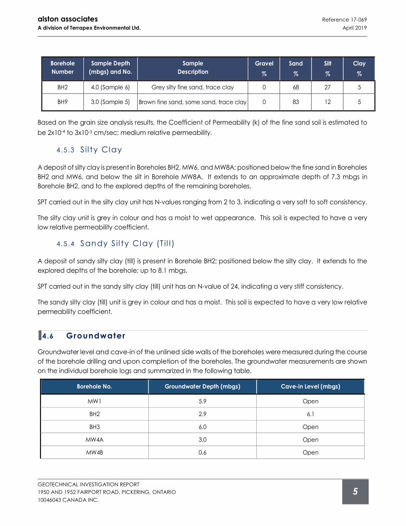
BH2 4.0 (Sample 6) Grey silty fine sand, trace clay 0 68 27 5
BH9 3.0 (Sample 5) Brown fine sand, some sand, trace clay 0 83 12 5
Based on the grain size analysis results, the Coefficient of Permeability (k) of the fine sand soil is estimated to
be 2x10⁻⁴ to 3x10⁻³ cm/sec; medium relative permeability.
4 .5 .3 Sil ty Clay
A deposit of silty clay is present in Boreholes BH2, MW6, and MW8A; positioned below the fine sand in Boreholes
BH2 and MW6, and below the silt in Borehole MW8A. It extends to an approximate depth of 7.3 mbgs in
Borehole BH2, and to the explored depths of the remaining boreholes.
SPT carried out in the silty clay unit has N-values ranging from 2 to 3, indicating a very soft to soft consistency.
The silty clay unit is grey in colour and has a moist to wet appearance. This soil is expected to have a very
low relative permeability coefficient.
4 .5 .4 Sandy S il ty Clay (T i l l )
A deposit of sandy silty clay (till) is present in Borehole BH2; positioned below the silty clay. It extends to the
explored depths of the borehole; up to 8.1 mbgs.
SPT carried out in the sandy silty clay (till) unit has an N-value of 24, indicating a very stiff consistency.
The sandy silty clay (till) unit is grey in colour and has a moist. This soil is expected to have a very low relative
permeability coefficient.
4 .6 Groundwater
Groundwater level and cave-in of the unlined side walls of the boreholes were measured during the course
of the borehole drilling and upon completion of the boreholes. The groundwater measurements are shown
on the individual borehole logs and summarized in the following table.
Borehole No. Groundwater Depth (mbgs) Cave-in Level (mbgs)
MW1 5.9 Open
BH2 2.9 6.1
BH3 6.0 Open
MW4A 3.0 Open
MW4B 0.6 Open

alston associates Reference 17-069
A division of Terrapex Environmental Ltd. April 2019
GEOTECHNICAL INVESTIGATION REPORT
1950 AND 1952 FAIRPORT ROAD, PICKERING, ONTARIO
10046043 CANADA INC.
6
Borehole No. Groundwater Depth (mbgs) Cave-in Level (mbgs)
BH5 0.9 0.9
MW6 2.6 5.2
BH7 3.7 Open
MW8A 4.9 Open
MW8B Dry Open
MW9 4.1 4.9
BH10 3.3 Open
Groundwater levels in the monitoring wells were measured on July 7, 12, 17, and 31, 2017. The groundwater
measurement results are shown in the following table.
Borehole No. Ground Elevation (m) Date Groundwater Depth (mbgs) Groundwater Elevation (m)
MW1 107.40
July 7 1.13 106.27
July 12 0.70 106.70
July 17 0.53 106.87
July 31 0.94 106.46
MW4A 105.35
July 7 0.71 104.64
July 12 0.63 104.72
July 17 0.51 104.84
July 31 0.83 104.52
MW4B 104.96
July 7 0.47 104.49
July 12 0.58 104.38
July 17 0.40 104.56
July 31 0.77 104.19
MW6 104.79
July 7 2.68 102.11
July 12 2.75 102.04
July 17 2.70 102.09
July 31 2.85 101.94
MW8A 104.99
July 7 3.16 101.83
July 12 3.20 101.79
July 17 3.17 101.82
July 31 3.30 101.69
MW8B 104.92
July 7 3.00 101.92
July 12 3.14 101.78
July 17 3.15 101.77
July 31 3.29 101.63
MW9 107.10
July 7 1.31 105.79
July 12 2.09 105.01
July 17 2.19 104.91
July 31 2.65 104.45
alston associates Reference 17-069
A division of Terrapex Environmental Ltd. April 2019
GEOTECHNICAL INVESTIGATION REPORT
1950 AND 1952 FAIRPORT ROAD, PICKERING, ONTARIO
10046043 CANADA INC.
7
Groundwater seepage was noted in Test Pits TP204, TP205, TP206, TP212 and TP213.
It should be noted that groundwater levels are subject to seasonal fluctuations. A higher groundwater level
condition will likely develop in the spring and following significant rainfall events.
Based on these groundwater measurements, the groundwater flow direction is from northeast to southwest.
5 DISCUSS ION AND RECOMMEND ATIONS
The following discussions and recommendations are based on the factual data obtained from the boreholes
advanced at the site by AA and are intended for use by the client and design architects and engineers only.
We understand that the proposed development will include the construction of a residential development
consisting of 30 homes with single level basements and municipal services.
A grading plan was not available at the time of the investigation, and accordingly the recommendations
provided in this report are considered to be preliminary in nature, subject for review and revision upon
completion of proposed grading plans.
Contractors bidding on this project or conducting work associated with this project should make their own
interpretation of the factual data and/or carry out their own investigations.
5 .1 Excavation
Based on the borehole findings, excavations for foundations, basements, sewer trenches and utilities are not
expected to pose any difficulty. Excavation of the soils at this site can be carried out with hydraulic
excavators.
All excavation work must be carried out in accordance with Occupational Health and Safety Act (OHSA).
With respect to OHSA, the near surface fill soil, the soft silty clay, and loose to compact fine sand situated
above the water table are expected to conform to Type 3 soils. The very stiff sandy silty clay (till) and dense
to very dense silt and fine sand soils are classified as Type 2 soils. Fill, sand, and silt soils situated below the
water table are classified as Type 4 soils.
For excavations through multiple soil types, the side slope geometry is governed by the soil with the highest
number designation. Excavation side-slopes should not be unduly left exposed to inclement weather.
Excavation slopes consisting of sandy soils will be prone to gullying in periods of wet weather, unless the slopes
are properly sheeted with tarpaulins.
Temporary excavations for slopes in Type 3 soil should not exceed 1.0 horizontal to 1.0 vertical. In the event
very loose and/or soft soils are encountered at shallow depths or within zones of persistent seepage, it will be
necessary to flatten the side slopes as necessary to achieve stable conditions. Excavations in Type 2 soil may
be cut with vertical side-walls within the lower 1.2 m height of excavation and 1.0 horizontal to 1.0 vertical
above this height. Slopes of sidewalls of excavations in Type 4 soil should not exceed 3.0 horizontal to 1.0
vertical.
alston associates Reference 17-069
A division of Terrapex Environmental Ltd. April 2019
GEOTECHNICAL INVESTIGATION REPORT
1950 AND 1952 FAIRPORT ROAD, PICKERING, ONTARIO
10046043 CANADA INC.
8
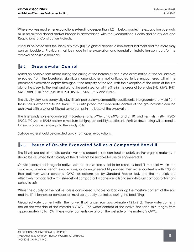
Where workers must enter excavations extending deeper than 1.2 m below grade, the excavation side-walls
must be suitably sloped and/or braced in accordance with the Occupational Health and Safety Act and
Regulations for Construction Projects.
It should be noted that the sandy silty clay (till) is a glacial deposit; a non-sorted sediment and therefore may
contain boulders. Provisions must be made in the excavation and foundation installation contracts for the
removal of possible boulders.
5 .2 Groundwater Control
Based on observations made during the drilling of the boreholes and close examination of the soil samples
extracted from the boreholes, significant groundwater is not anticipated to be encountered within the
presumed excavation depths throughout the majority of the Site, with the exception of the areas of the site
along the creek to the west and along the south section of the Site in the areas of Boreholes BH2, MW6, BH7,
MW8, and BH10, and Test Pits TP204, TP205, TP206, TP212 and TP213.
The silt, silty clay, and sandy silty clay till soils possess low permeability coefficients; the groundwater yield from
these soil is expected to be small. It is anticipated that adequate control of the groundwater can be
achieved with a series of filtered sump pumps in the base of the excavation.
The fine sandy soils encountered in Boreholes BH2, MW6, BH7, MW8, and BH10, and Test Pits TP204, TP205,
TP206, TP212 and TP213 possess a medium to high permeability coefficient. Positive dewatering will be require
for excavations extending into the sandy soils.
Surface water should be directed away from open excavations.
5 .3 Reuse of On-si te Excavated Soi l as a Compacted Backfi l l
The fill soils present at the site contain variable proportions of construction debris and/or organic material. It
should be assumed that majority of the fill will not be suitable for use as engineered fill.
On-site excavated inorganic native soils are considered suitable for reuse as backfill material within the
roadway, pipeline trench excavations, or as engineered fill provided their water content is within 2% of
their optimum water contents (OWC) as determined by Standard Proctor test, and the materials are
effectively compacted with a sheepsfoot compactor for cohesive soils or a smooth drum compactor for non-
cohesive soils.
While the quality of the native soils is considered suitable for backfilling; the moisture content of the soils
and the lift thickness for compaction must be properly controlled during the backfilling.
Measured water content within the native silt soil ranges from approximately 12 to 21%. These water contents
are on the wet side of the material’s OWC. The water content of the native fine sand soils ranges from
approximately 15 to 16%. These water contents are also on the wet side of the material’s OWC.
alston associates Reference 17-069
A division of Terrapex Environmental Ltd. April 2019
GEOTECHNICAL INVESTIGATION REPORT
1950 AND 1952 FAIRPORT ROAD, PICKERING, ONTARIO
10046043 CANADA INC.
9
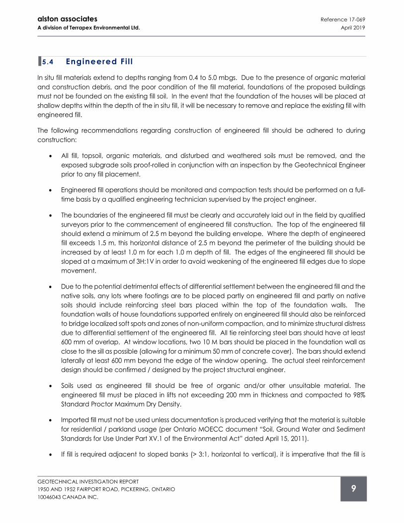
5 .4 Engineered Fi l l
In situ fill materials extend to depths ranging from 0.4 to 5.0 mbgs. Due to the presence of organic material
and construction debris, and the poor condition of the fill material, foundations of the proposed buildings
must not be founded on the existing fill soil. In the event that the foundation of the houses will be placed at
shallow depths within the depth of the in situ fill, it will be necessary to remove and replace the existing fill with
engineered fill.
The following recommendations regarding construction of engineered fill should be adhered to during
construction:
• All fill, topsoil, organic materials, and disturbed and weathered soils must be removed, and the
exposed subgrade soils proof-rolled in conjunction with an inspection by the Geotechnical Engineer
prior to any fill placement.
• Engineered fill operations should be monitored and compaction tests should be performed on a full-
time basis by a qualified engineering technician supervised by the project engineer.
• The boundaries of the engineered fill must be clearly and accurately laid out in the field by qualified
surveyors prior to the commencement of engineered fill construction. The top of the engineered fill
should extend a minimum of 2.5 m beyond the building envelope. Where the depth of engineered
fill exceeds 1.5 m, this horizontal distance of 2.5 m beyond the perimeter of the building should be
increased by at least 1.0 m for each 1.0 m depth of fill. The edges of the engineered fill should be
sloped at a maximum of 3H:1V in order to avoid weakening of the engineered fill edges due to slope
movement.
• Due to the potential detrimental effects of differential settlement between the engineered fill and the
native soils, any lots where footings are to be placed partly on engineered fill and partly on native
soils should include reinforcing steel bars placed within the top of the foundation walls. The
foundation walls of house foundations supported entirely on engineered fill should also be reinforced
to bridge localized soft spots and zones of non-uniform compaction, and to minimize structural distress
due to differential settlement of the engineered fill. All tie reinforcing steel bars should have at least
600 mm of overlap. At window locations, two 10 M bars should be placed in the foundation wall as
close to the sill as possible (allowing for a minimum 50 mm of concrete cover). The bars should extend
laterally at least 600 mm beyond the edge of the window opening. The actual steel reinforcement
design should be confirmed / designed by the project structural engineer.
• Soils used as engineered fill should be free of organic and/or other unsuitable material. The
engineered fill must be placed in lifts not exceeding 200 mm in thickness and compacted to 98%
Standard Proctor Maximum Dry Density.
• Imported fill must not be used unless documentation is produced verifying that the material is suitable
for residential / parkland usage (per Ontario MOECC document “Soil, Ground Water and Sediment
Standards for Use Under Part XV.1 of the Environmental Act” dated April 15, 2011).
• If fill is required adjacent to sloped banks (> 3:1, horizontal to vertical), it is imperative that the fill is
alston associates Reference 17-069
A division of Terrapex Environmental Ltd. April 2019
GEOTECHNICAL INVESTIGATION REPORT
1950 AND 1952 FAIRPORT ROAD, PICKERING, ONTARIO
10046043 CANADA INC.
10
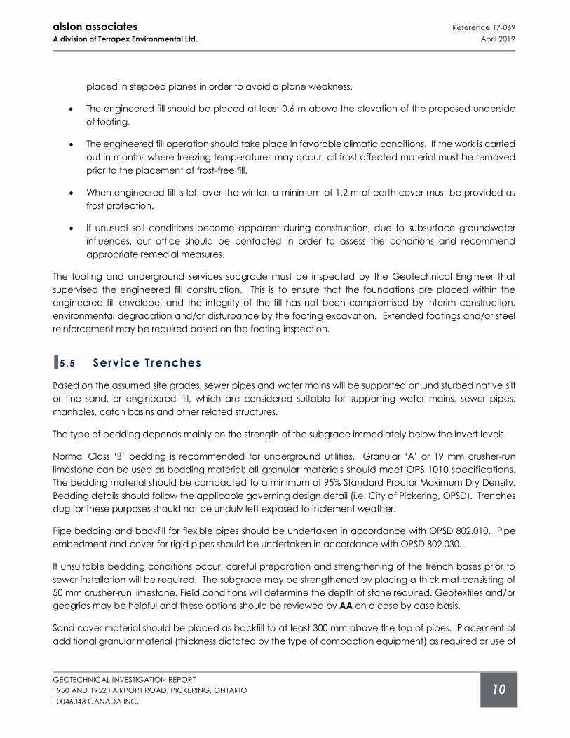
placed in stepped planes in order to avoid a plane weakness.
• The engineered fill should be placed at least 0.6 m above the elevation of the proposed underside
of footing.
• The engineered fill operation should take place in favorable climatic conditions. If the work is carried
out in months where freezing temperatures may occur, all frost affected material must be removed
prior to the placement of frost-free fill.
• When engineered fill is left over the winter, a minimum of 1.2 m of earth cover must be provided as
frost protection.
• If unusual soil conditions become apparent during construction, due to subsurface groundwater
influences, our office should be contacted in order to assess the conditions and recommend
appropriate remedial measures.
The footing and underground services subgrade must be inspected by the Geotechnical Engineer that
supervised the engineered fill construction. This is to ensure that the foundations are placed within the
engineered fill envelope, and the integrity of the fill has not been compromised by interim construction,
environmental degradation and/or disturbance by the footing excavation. Extended footings and/or steel
reinforcement may be required based on the footing inspection.
5 .5 Service Trenches
Based on the assumed site grades, sewer pipes and water mains will be supported on undisturbed native silt
or fine sand, or engineered fill, which are considered suitable for supporting water mains, sewer pipes,
manholes, catch basins and other related structures.
The type of bedding depends mainly on the strength of the subgrade immediately below the invert levels.
Normal Class ‘B’ bedding is recommended for underground utilities. Granular ‘A’ or 19 mm crusher-run
limestone can be used as bedding material; all granular materials should meet OPS 1010 specifications.
The bedding material should be compacted to a minimum of 95% Standard Proctor Maximum Dry Density.
Bedding details should follow the applicable governing design detail (i.e. City of Pickering, OPSD). Trenches
dug for these purposes should not be unduly left exposed to inclement weather.
Pipe bedding and backfill for flexible pipes should be undertaken in accordance with OPSD 802.010. Pipe
embedment and cover for rigid pipes should be undertaken in accordance with OPSD 802.030.
If unsuitable bedding conditions occur, careful preparation and strengthening of the trench bases prior to
sewer installation will be required. The subgrade may be strengthened by placing a thick mat consisting of
50 mm crusher-run limestone. Field conditions will determine the depth of stone required. Geotextiles and/or
geogrids may be helpful and these options should be reviewed by AA on a case by case basis.
Sand cover material should be placed as backfill to at least 300 mm above the top of pipes. Placement of
additional granular material (thickness dictated by the type of compaction equipment) as required or use of
alston associates Reference 17-069
A division of Terrapex Environmental Ltd. April 2019
GEOTECHNICAL INVESTIGATION REPORT
1950 AND 1952 FAIRPORT ROAD, PICKERING, ONTARIO
10046043 CANADA INC.
11
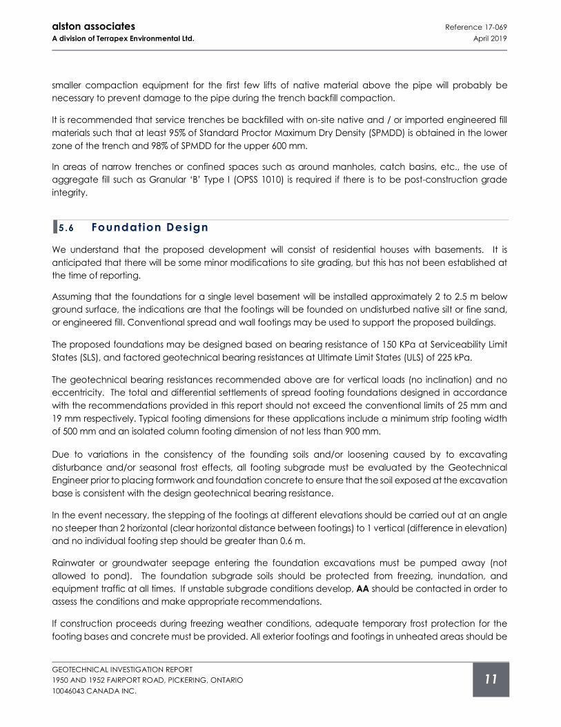
smaller compaction equipment for the first few lifts of native material above the pipe will probably be
necessary to prevent damage to the pipe during the trench backfill compaction.
It is recommended that service trenches be backfilled with on-site native and / or imported engineered fill
materials such that at least 95% of Standard Proctor Maximum Dry Density (SPMDD) is obtained in the lower
zone of the trench and 98% of SPMDD for the upper 600 mm.
In areas of narrow trenches or confined spaces such as around manholes, catch basins, etc., the use of
aggregate fill such as Granular ‘B’ Type I (OPSS 1010) is required if there is to be post-construction grade
integrity.
5 .6 Foundation Design
We understand that the proposed development will consist of residential houses with basements. It is
anticipated that there will be some minor modifications to site grading, but this has not been established at
the time of reporting.
Assuming that the foundations for a single level basement will be installed approximately 2 to 2.5 m below
ground surface, the indications are that the footings will be founded on undisturbed native silt or fine sand,
or engineered fill. Conventional spread and wall footings may be used to support the proposed buildings.
The proposed foundations may be designed based on bearing resistance of 150 KPa at Serviceability Limit
States (SLS), and factored geotechnical bearing resistances at Ultimate Limit States (ULS) of 225 kPa.
The geotechnical bearing resistances recommended above are for vertical loads (no inclination) and no
eccentricity. The total and differential settlements of spread footing foundations designed in accordance
with the recommendations provided in this report should not exceed the conventional limits of 25 mm and
19 mm respectively. Typical footing dimensions for these applications include a minimum strip footing width
of 500 mm and an isolated column footing dimension of not less than 900 mm.
Due to variations in the consistency of the founding soils and/or loosening caused by to excavating
disturbance and/or seasonal frost effects, all footing subgrade must be evaluated by the Geotechnical
Engineer prior to placing formwork and foundation concrete to ensure that the soil exposed at the excavation
base is consistent with the design geotechnical bearing resistance.
In the event necessary, the stepping of the footings at different elevations should be carried out at an angle
no steeper than 2 horizontal (clear horizontal distance between footings) to 1 vertical (difference in elevation)
and no individual footing step should be greater than 0.6 m.
Rainwater or groundwater seepage entering the foundation excavations must be pumped away (not
allowed to pond). The foundation subgrade soils should be protected from freezing, inundation, and
equipment traffic at all times. If unstable subgrade conditions develop, AA should be contacted in order to
assess the conditions and make appropriate recommendations.
If construction proceeds during freezing weather conditions, adequate temporary frost protection for the
footing bases and concrete must be provided. All exterior footings and footings in unheated areas should be
alston associates Reference 17-069
A division of Terrapex Environmental Ltd. April 2019
GEOTECHNICAL INVESTIGATION REPORT
1950 AND 1952 FAIRPORT ROAD, PICKERING, ONTARIO
10046043 CANADA INC.
12
provided by at least 1.2 m of soil cover or equivalent artificial thermal insulation for frost protection purposes.
5 .7 Basement Floors
Excavations for basements are expected to extend to an approximate depth of 2 m below the existing
ground surface. It is expected that the subgrade below the basement floors will consist of undisturbed native
silt or fine sand, or engineered fill; suitable for slab-on-grade construction.
Subgrade preparation should include the removal of any wet, soft/loose and disturbed soils. After removal
of all unsuitable materials, the subgrade should be inspected and adjudged as satisfactory before preparing
the granular base course. Any soft or unsuitable subgrade areas should be sub-excavated and replaced
with suitable approved compacted backfill; placed in maximum lifts of 200 mm thickness and compacted
to at least 98% of SPMDD.
It is recommended that a combined moisture barrier and a levelling course, having a minimum thickness of
150 mm and comprised of free draining material such as 19 mm clear stone (OPSS 1004) compacted by
vibration to a dense state be placed under the floor slab.
The basements of the proposed buildings must be provided with perimeter drainage. The perimeter drainage
system should consist of weeping pipes 100 mm in diameter placed adjacent to the exterior wall footing. The
weeping tiles must be wrapped with filter fabric and covered with a minimum of 150 mm of clear stone.
The basement wall backfill for a minimum lateral distance of 0.6 m out from the wall should consist of free-
draining material such as OPSS Granular ‘B’ Type I. The native soil may be used to backfill excavations along
foundation walls provided that a suitable alternative drainage cellular media is placed on the wall. Damp
proofing must be applied to the exterior basement walls.
The perimeter foundation drains must be connected to a positive frost-free outlet from which the water can
be removed, or connected to a sump located in the basement. The water from the sump must be pumped
out to a suitable discharge point.
The installation of the perimeter drains as well as the outlet must conform to the applicable plumbing code
requirements.
Sub-floor drains may also be required below the basement of the houses for this development. It is
recommended that a decision in this regard be made once final grade and basement floor elevations have
been established.
The soils at this site are susceptible to frost effects which would have the potential to deform hard landscaping
adjacent to the buildings. At locations where buildings are expected to have flush entrances, care must be
taken in detailing the exterior slabs / sidewalks, providing insulation / drainage / non-frost susceptible backfill
to maintain the flush threshold during freezing weather conditions.
Part 9 of the Ontario Building Code, “Housing and Small Buildings” should be referred to for standard
practices.
alston associates Reference 17-069
A division of Terrapex Environmental Ltd. April 2019
GEOTECHNICAL INVESTIGATION REPORT
1950 AND 1952 FAIRPORT ROAD, PICKERING, ONTARIO
10046043 CANADA INC.
13
5 .8 Pavement Design
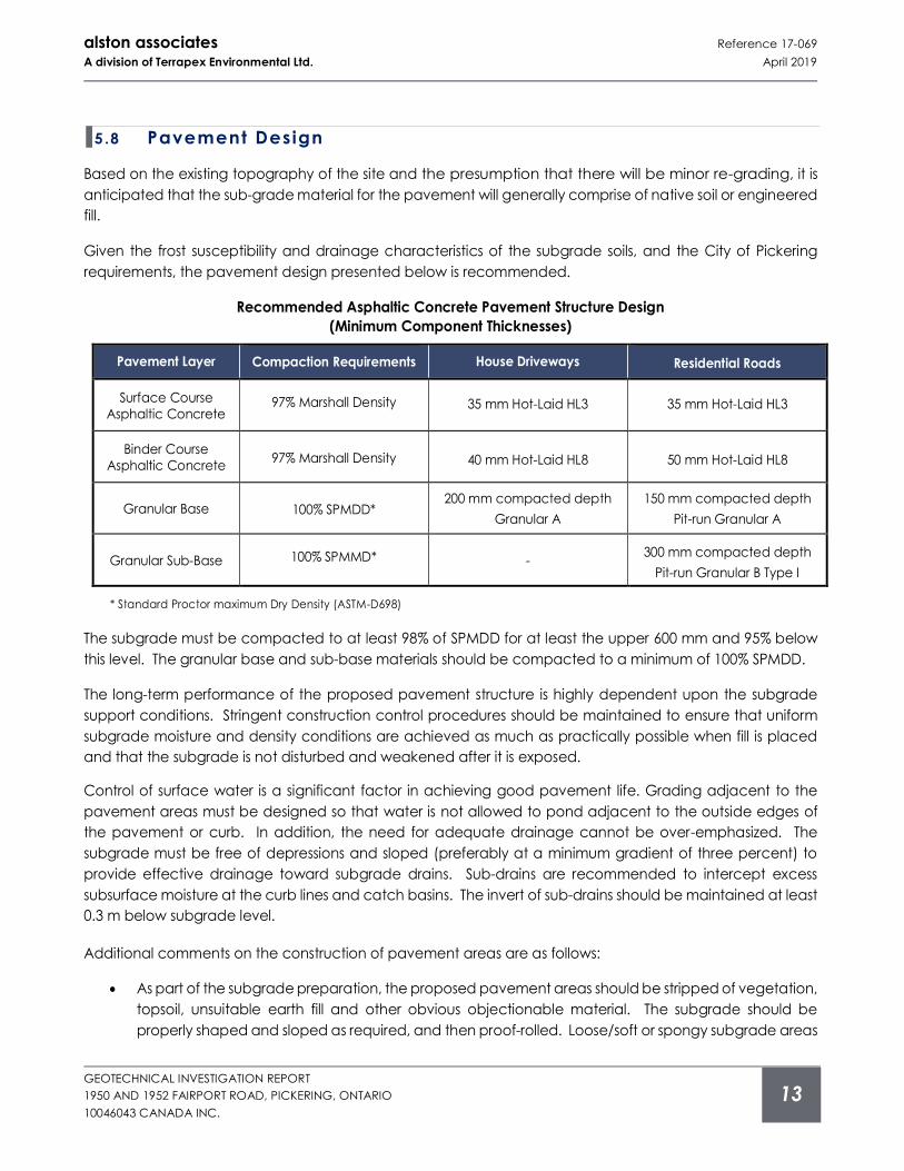
Based on the existing topography of the site and the presumption that there will be minor re-grading, it is
anticipated that the sub-grade material for the pavement will generally comprise of native soil or engineered
fill.
Given the frost susceptibility and drainage characteristics of the subgrade soils, and the City of Pickering
requirements, the pavement design presented below is recommended.
Recommended Asphaltic Concrete Pavement Structure Design
(Minimum Component Thicknesses)
Pavement Layer Compaction Requirements House Driveways Residential Roads
Surface Course
Asphaltic Concrete 97% Marshall Density 35 mm Hot-Laid HL3 35 mm Hot-Laid HL3
Binder Course
Asphaltic Concrete 97% Marshall Density 40 mm Hot-Laid HL8 50 mm Hot-Laid HL8
Granular Base 100% SPMDD* 200 mm compacted depth
Granular A
150 mm compacted depth
Pit-run Granular A
Granular Sub-Base 100% SPMMD* - 300 mm compacted depth
Pit-run Granular B Type I
* Standard Proctor maximum Dry Density (ASTM-D698)
The subgrade must be compacted to at least 98% of SPMDD for at least the upper 600 mm and 95% below
this level. The granular base and sub-base materials should be compacted to a minimum of 100% SPMDD.
The long-term performance of the proposed pavement structure is highly dependent upon the subgrade
support conditions. Stringent construction control procedures should be maintained to ensure that uniform
subgrade moisture and density conditions are achieved as much as practically possible when fill is placed
and that the subgrade is not disturbed and weakened after it is exposed.
Control of surface water is a significant factor in achieving good pavement life. Grading adjacent to the
pavement areas must be designed so that water is not allowed to pond adjacent to the outside edges of
the pavement or curb. In addition, the need for adequate drainage cannot be over-emphasized. The
subgrade must be free of depressions and sloped (preferably at a minimum gradient of three percent) to
provide effective drainage toward subgrade drains. Sub-drains are recommended to intercept excess
subsurface moisture at the curb lines and catch basins. The invert of sub-drains should be maintained at least
0.3 m below subgrade level.
Additional comments on the construction of pavement areas are as follows:
• As part of the subgrade preparation, the proposed pavement areas should be stripped of vegetation,
topsoil, unsuitable earth fill and other obvious objectionable material. The subgrade should be
properly shaped and sloped as required, and then proof-rolled. Loose/soft or spongy subgrade areas
alston associates Reference 17-069
A division of Terrapex Environmental Ltd. April 2019
GEOTECHNICAL INVESTIGATION REPORT
1950 AND 1952 FAIRPORT ROAD, PICKERING, ONTARIO
10046043 CANADA INC.
14
should be sub-excavated and replaced with suitable approved material compacted to at least 98%
of SPMDD.
• Where new fill is needed to raise the grade or replace disturbed portions of the subgrade, excavated
inorganic soils or similar clean imported fill materials may be used, provided their moisture content is
maintained within 2 % of the soil’s optimum moisture content. All fill must be placed and compacted
to not less than 98% of SPMDD.
• The most severe loading conditions on pavement areas and the subgrade may occur during
construction during wet and un-drained conditions. Consequently, special provisions such as
restricted lanes, half-loads during paving etc., may be required, especially if construction is carried
out during unfavourable weather.
• For fine-grained soils, as encountered at the site, the degree of compaction specification alone
cannot ensure distress free subgrade. Proof-rolling must be carried out and witnessed by AA
personnel for final recommendations of sub-base thicknesses.
• In the event that pavement construction takes place in the spring thaw, the late fall, or following
periods of significant rainfall, it should be anticipated that an increase in thickness of the granular sub-
base layer will be required to compensate for reduced subgrade strength.
5 .9 Earthquake Design Parameters
The 2012 Ontario Building Code (OBC) stipulates the methodology for earthquake design analysis, as set out
in Subsection 4.1.8.7. The determination of the type of analysis is predicated on the importance of the
structure, the spectral response acceleration and the site classification.
The parameters for determination of the Site Classification for Seismic Site Response are set out in Table
4.1.8.4.A of the 2012 OBC. The classification is based on the determination of the average shear wave
velocity in the top 30 metres of the site stratigraphy, where shear wave velocity (vs) measurements have been
taken. In the absence of such measurements, the classification is estimated on the basis of empirical analysis
of undrained shear strength or penetration resistance. The applicable penetration resistance is that which
has been corrected to a rod energy efficiency of 60% of the theoretical maximum or the (N60) value.
Based on the borehole information, the subsurface stratigraphy generally comprises surficial topsoil underlain
by a layer of fill, followed by native loose to very dense silt and fine sand. Based on the above, the site
designation for seismic analysis is Class D (“Stiff soil”) according to Table 4.1.8.4.A from the quoted code.
The site specific 5% damped spectral acceleration coefficients, and the peak ground acceleration factors
are provided in the 2012 Ontario Building Code - Supplementary Standards SB-1 (September 14, 2012), Table
1.2, location Pickering, Ontario.
5 .10 Lateral Earth Pressure
Parameters used in the determination of earth pressure acting on temporary shoring walls are defined below.
alston associates Reference 17-069
A division of Terrapex Environmental Ltd. April 2019
GEOTECHNICAL INVESTIGATION REPORT
1950 AND 1952 FAIRPORT ROAD, PICKERING, ONTARIO
10046043 CANADA INC.
15
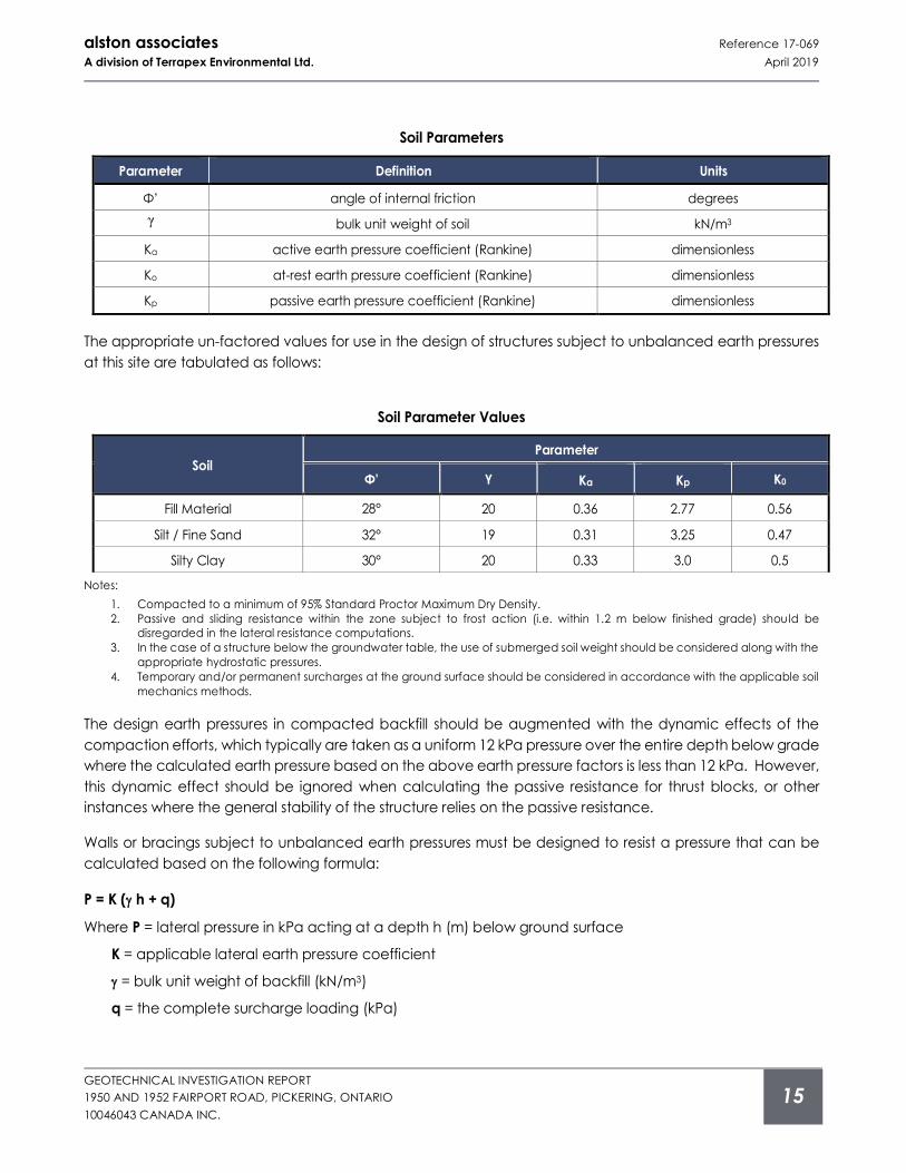
Soil Parameters
Parameter Definition Units
Φ’ angle of internal friction degrees
γ bulk unit weight of soil kN/m3
Ka active earth pressure coefficient (Rankine) dimensionless
Ko at-rest earth pressure coefficient (Rankine) dimensionless
Kp passive earth pressure coefficient (Rankine) dimensionless
The appropriate un-factored values for use in the design of structures subject to unbalanced earth pressures
at this site are tabulated as follows:
Soil Parameter Values
Soil Parameter
Φ’ γ Ka Kp K0
Fill Material 28° 20 0.36 2.77 0.56
Silt / Fine Sand 32° 19 0.31 3.25 0.47
Silty Clay 30° 20 0.33 3.0 0.5
Notes:
1. Compacted to a minimum of 95% Standard Proctor Maximum Dry Density.
2. Passive and sliding resistance within the zone subject to frost action (i.e. within 1.2 m below finished grade) should be
disregarded in the lateral resistance computations.
3. In the case of a structure below the groundwater table, the use of submerged soil weight should be considered along with the
appropriate hydrostatic pressures.
4. Temporary and/or permanent surcharges at the ground surface should be considered in accordance with the applicable soil
mechanics methods.
The design earth pressures in compacted backfill should be augmented with the dynamic effects of the
compaction efforts, which typically are taken as a uniform 12 kPa pressure over the entire depth below grade
where the calculated earth pressure based on the above earth pressure factors is less than 12 kPa. However,
this dynamic effect should be ignored when calculating the passive resistance for thrust blocks, or other
instances where the general stability of the structure relies on the passive resistance.
Walls or bracings subject to unbalanced earth pressures must be designed to resist a pressure that can be
calculated based on the following formula:
P = K ( h + q)
Where P = lateral pressure in kPa acting at a depth h (m) below ground surface
K = applicable lateral earth pressure coefficient
= bulk unit weight of backfill (kN/m3)
q = the complete surcharge loading (kPa)
alston associates Reference 17-069
A division of Terrapex Environmental Ltd. April 2019
GEOTECHNICAL INVESTIGATION REPORT
1950 AND 1952 FAIRPORT ROAD, PICKERING, ONTARIO
10046043 CANADA INC.
16
This equation assumes that free-draining backfill and positive drainage is provided to ensure that there is no
hydrostatic pressure acting in conjunction with the earth pressure.
The coefficient of earth pressure at rest (Ko) should be used in the calculation of the earth pressure on the
basement walls.
Resistance to sliding of earth retaining structures is developed by friction between the base of the footing
and the soil. This friction (R) depends on the normal load on the soil contact (N) and the frictional resistance
of the soil (tan Φ’) expressed as: R = N tan Φ’. This is an ultimate resistance value and does not contain a
factor of safety.
5 .11 Chemical Characterizat ion of Subsurface Soi l
Two (2) native soil samples obtained from Boreholes BH5 (Sample 3; 1.5 mbgs and Sample 5; 3.0 mbgs) were
submitted to AGAT Laboratories for pH index test and water-soluble sulphate content to determine the
potential of attacking the subsurface concrete.
The test results revealed that the pH index of the soil samples are 7.87 and 8.04; indicating a slight alkalinity.
The water-soluble sulphate content of the soil samples are 0.0013% and 0.0062%. The concentration of water-
soluble sulphate content of the tested samples is below the CSA Standard of 0.1% water-soluble sulphate
(Table 12 of CSA A23.1, Requirements for Concrete Subjected to Sulphate Attack). Special concrete mixes
against sulphate attack is therefore not required for the sub-surface concrete of the proposed buildings.
The Certificate of Analysis provided by the analytical chemical testing laboratory is contained in Appendix F
of this report.
6 STABIL I TY ASSESSMENT OF CREEK BANK
The east bank of Dunbarton Creek abuts the west boundary of the site. It approximates 170 m in length; the
full length of the properties. It is aligned with dense vegetation and trees throughout.
The survey drawing prepared by J.D. Barnes Limited reveals that the Top of Bank has elevations ranging from
approximately 105.5 m at the north property boundary to 104.5 m at the south property boundary. Using the
contour elevations as shown on the survey drawing, the bottom of the creek elevation ranges from
approximately 101.2 to 102.4. m. The creek bank ranges in height from approximately 3 to 4 m. The bankfull
width of the creek is approximately 3 m.
The north portion of the creek bank has an overall gradient of 36º (to horizontal), the center portion is 20º,
and the southern portion is 34º.
The conditions of the creek bank within the property were inspected on June 27, 2017 following the technical
guidelines for Geotechnical Principles for Stable Slopes as stipulated by Ontario Ministry of Natural Resources
(MNR).
alston associates Reference 17-069
A division of Terrapex Environmental Ltd. April 2019
GEOTECHNICAL INVESTIGATION REPORT
1950 AND 1952 FAIRPORT ROAD, PICKERING, ONTARIO
10046043 CANADA INC.
17
The Erosion Hazard Limit is defined by the following three (3) components:
• Stable slope allowance
• Toe erosion allowance
• Erosion access allowance
6 .1 Stable Slope Al lowance
Soil strength parameters used in the slope stability analyses were based on the results of the in situ Standard
Penetration Test, together with an assessment on the soil type using the results of the grain size analyses and
Atterberg Limits tests.
Boreholes BH2, MW6, and MW8A were put down near the crest of the creek bank to generate soil profiles at
three sections for the analysis. The borehole findings revealed that fill material comprises the majority of the
slope. The ground water level was determined using the monitoring wells installed in the boreholes and the
water level in the creek.
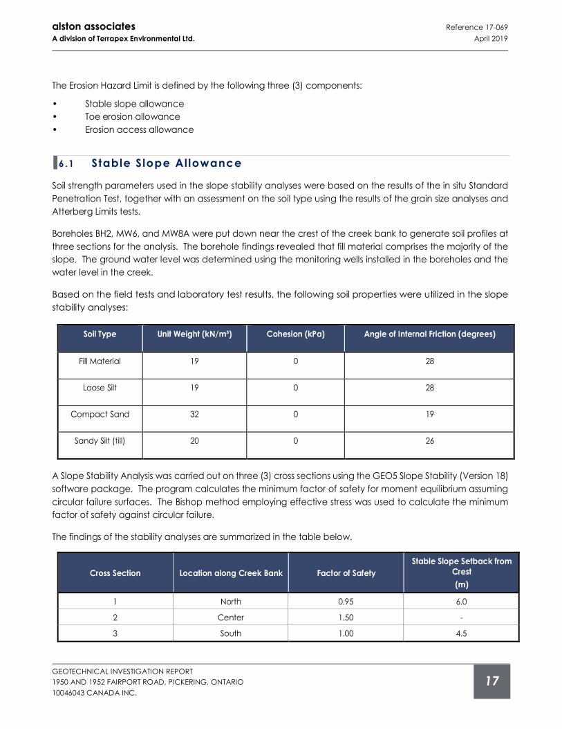
Based on the field tests and laboratory test results, the following soil properties were utilized in the slope
stability analyses:
Soil Type Unit Weight (kN/m³) Cohesion (kPa) Angle of Internal Friction (degrees)
Fill Material 19 0 28
Loose Silt 19 0 28
Compact Sand 32 0 19
Sandy Silt (till) 20 0 26
A Slope Stability Analysis was carried out on three (3) cross sections using the GEO5 Slope Stability (Version 18)
software package. The program calculates the minimum factor of safety for moment equilibrium assuming
circular failure surfaces. The Bishop method employing effective stress was used to calculate the minimum
factor of safety against circular failure.
The findings of the stability analyses are summarized in the table below.
Cross Section Location along Creek Bank Factor of Safety
Stable Slope Setback from
Crest
(m)
1 North 0.95 6.0
2 Center 1.50 -
3 South 1.00 4.5
alston associates Reference 17-069
A division of Terrapex Environmental Ltd. April 2019
GEOTECHNICAL INVESTIGATION REPORT
1950 AND 1952 FAIRPORT ROAD, PICKERING, ONTARIO
10046043 CANADA INC.
18
The locations of the cross sections are presented on the Borehole Location Plan in Appendix B; the analysis
results in Appendix G.
TRCA stipulates that the minimum factor of safety required against sliding to consider a slope stable is 1.50. A
setback from the crest where the factor of safety exceeds 1.50 is required for slopes which do not satisfy the
criterion.
In this regard, it will be necessary to establish the stable slope inclination. Accordingly, a slope line of 1V:2.65H
(20.7˚ angle to the horizontal) will provide a safety factor of 1.5 against sliding failure at all 3 Slope Sections.
6 .2 Toe Erosion Al lowance
The slope inspection undertaken by AA revealed that a shallow watercourse, approximately 100 to 300 mm
in depth, flows along the creek in a north to south direction. Evidence of active erosion of the toe of the bank
were observed. The soil exposed at the toe of the creek bank is fine sand.
The toe erosion allowance for a sand material with active erosion is 8 to 15 m. Given that the bankfull width
of the creek is approximately 3 m and the water flow velocity in the creek very slow, the minimum 8 m erosion
allowance should suffice.
6 .3 Erosion Access Al lowance
An Erosion Access Allowance of either 6 or 10 m is required by TRCA.
6 .4 Conclusion
A Stable Slope Allowance ranging from 0 to 6 m measured from the crest of the slope is required for the
subject creek bank. The Toe Erosion Allowance requires a setback distance of 8 m.
The Long Term Stable Top of Slope Line (LTSTSL) which includes the Stable Slope Allowance and Toe Erosion
Allowance has been presented on the Borehole Location Plan in Appendix B.
The Erosion Access Allowance of 6 to 10 m as stipulated by TRCA will be required in addition to the LTSTSL.
alston associates Reference 17-069
A division of Terrapex Environmental Ltd. April 2019
GEOTECHNICAL INVESTIGATION REPORT
1950 AND 1952 FAIRPORT ROAD, PICKERING, ONTARIO
10046043 CANADA INC.
19
7 L IMITATIONS OF REPO RT
The Limitations of Report, as quoted in Appendix ‘A’, are an integral part of this report.
Yours respectfully
alston associates
A division of Terrapex Environmental Ltd.
Kellen Campbell, C.Tech Vic Nersesian, P. Eng.
Project Manager Vice President, Geotechnical Services

alston associates Reference 17-069
A division of Terrapex Environmental Ltd. April 2019
GEOTECHNICAL INVESTIGATION REPORT
1950 AND 1952 FAIRPORT ROAD, PICKERING, ONTARIO
10046043 CANADA INC.
APPENDIX A LIMITATIONS OF REPORT
alston associates Reference 17-069
A division of Terrapex Environmental Ltd. April 2019
GEOTECHNICAL INVESTIGATION REPORT
1950 AND 1952 FAIRPORT ROAD, PICKERING, ONTARIO
10046043 CANADA INC.
l imi tat ions of report
The conclusions and recommendations in this report are based on information determined at the inspection
locations. Soil and groundwater conditions between and beyond the test holes may differ from those
encountered at the test hole locations, and conditions may become apparent during construction which
could not be detected or anticipated at the time of the soil investigation.
The design recommendations given in this report are applicable only to the project described in the text, and
then only if constructed substantially in accordance with details of alignment and elevations stated in the
report. Since all details of the design may not be known to us, in our analysis certain assumptions had to be
made as set out in this report. The actual conditions may, however, vary from those assumed, in which case
changes and modifications may be required to our recommendations.
This report was prepared for 10046043 Canada Inc. by Alston Associates. The material in it reflects Alston
Associates judgement in light of the information available to it at the time of preparation. Any use which a
Third Party makes of this report, or any reliance on decisions which the Third Party may make based on it, are
the sole responsibility of such Third Parties.
We recommend, therefore, that we be retained during the final design stage to review the design drawings
and to verify that they are consistent with our recommendations or the assumptions made in our analysis. We
recommend also that we be retained during construction to confirm that the subsurface conditions
throughout the site do not deviate materially from those encountered in the test holes. In cases where these
recommendations are not followed, the company’s responsibility is limited to accurately interpreting the
conditions encountered at the test holes, only.
The comments given in this report on potential construction problems and possible methods are intended for
the guidance of the design engineer, only. The number of inspection locations may not be sufficient to
determine all the factors that may affect construction methods and costs. The contractors bidding on this
project or undertaking the construction should, therefore, make their own interpretation of the factual
information presented and draw their own conclusions as to how the subsurface conditions may affect their
work.
alston associates Reference 17-069
A division of Terrapex Environmental Ltd. April 2019
GEOTECHNICAL INVESTIGATION REPORT
1950 AND 1952 FAIRPORT ROAD, PICKERING, ONTARIO
10046043 CANADA INC.
APPENDIX B BOREHOLE LOCATION PLAN
MONITORING WELL SF
APRIL 2019
17-069
AS SHOWN
FIGURE 1DRAWING #
DRAWN
DATE
PROJECT #
CLIENT
LEGEND
SCALE
CHECKED
0 25m 50m
(APPROXIMATE)
BOREHOLE LOCATION PLAN
SOURCE: ILLUSTRATING LOT 14 AND PART OF LOTS 22 TO 29 REGISTAR'S COMPILED PLAN 818 CITY OF PICKERING BY J.D. BARNES LIMITED, 2017.
VUMAP, FIRST BASE SOLUTIONS, 2016 IMAGERY AND TOPOGRAPHIC PLAN BOREHOLE
1950 AND 1952 FAIRPORT ROAD PICKERING, ONTARIO
10046043 CANADA INC.
VN
APPROXIMATE SITE BOUNDARYAPPROXIMATE SITE BOUNDARY
FA
IRP
OR
T R
OA
DFA
IRP
OR
T R
OA
DMW1MW1
MW4AMW4A
MW9MW9
MW8AMW8A
MW4BMW4B
MW8BMW8B
MW6MW6
BH7BH7
BH5BH5
BH3BH3BH2BH2
BH10BH10
CROSS SECTION 3CROSS SECTION 3
CROSS SECTION 2CROSS SECTION 2
CROSS SECTION 1CROSS SECTION 1
STABLE TOP OF SLOPE LINESTABLE TOP OF SLOPE LINE
STABLE TOP OF SLOPE LINESTABLE TOP OF SLOPE LINE
MONITORING WELL SF
APRIL 2019
17-069
AS SHOWN
FIGURE 2DRAWING #
DRAWN
DATE
PROJECT #
CLIENT
LEGEND
SCALE
CHECKED0 25m 50m
(APPROXIMATE)
DEPTH OF FILL
SOURCE: VUMAP, FIRST BASE SOLUTIONS, 2017 IMAGERY AND TOPOGRAPHIC PLAN ILLUSTRATING LOT 14 AND PART OF LOTS 22 TO 29 REGISTAR'S COMPILED PLAN 818 CITY OF PICKERING BY J.D. BARNES LIMITED, 2017.
BOREHOLE
1950 AND 1952 FAIRPORT ROAD PICKERING, ONTARIO
10046043 CANADA INC.
TEST PIT
DEPTH OF FILL3.0m
VN
APPROXIMATE SITE BOUNDARYAPPROXIMATE SITE BOUNDARY
FA
IRP
OR
T R
OA
DFA
IRP
OR
T R
OA
D
BH7BH7
BH5BH5
BH3BH3
BH2BH2
BH10BH10
MW1MW1
MW4AMW4A
MW9MW9
MW8AMW8A
MW4BMW4B
MW8BMW8B
MW6MW6
MW201MW201
TP205TP205
TP204TP204TP203TP203
TP206TP206 TP202TP202
TP207TP207
TP201TP201
TP208TP208
TP209TP209
TP210TP210
TP211TP211
TP212TP212
TP213TP213
TP214TP214
TP215TP215
TP216TP216 TP217TP217
TP218TP218
2.7m2.7m
0.6m0.6m
0.8m0.8m
3.8m3.8m
3.3m3.3m
0.6m0.6m
1.4m1.4m
1.1m1.1m
4.9m4.9m
2.2m2.2m
3.4m3.4m
3.0+m3.0+m
>3.1m>3.1m3.2m3.2m
3.5m3.5m 5.0m5.0m
3.5m3.5m
3.7m3.7m
>3.5m>3.5m
3.8m3.8m
3.0m3.0m
3.0m3.0m
>3.0m>3.0m
>3.0m>3.0m
0.6m0.6m
2.0m2.0m
0.5m0.5m 0.6m0.6m
0.4m0.4m
alston associates Reference 17-069
A division of Terrapex Environmental Ltd. April 2019
GEOTECHNICAL INVESTIGATION REPORT
1950 AND 1952 FAIRPORT ROAD, PICKERING, ONTARIO
10046043 CANADA INC.
APPENDIX C BOREHOLE LOG SHEETS
0
0.5
1
1.5
2
2.5
3
3.5
4
4.5
5
5.5
6
6.5
107
106.5
106
105.5
105
104.5
104
103.5
103
102.5
102
101.5
101
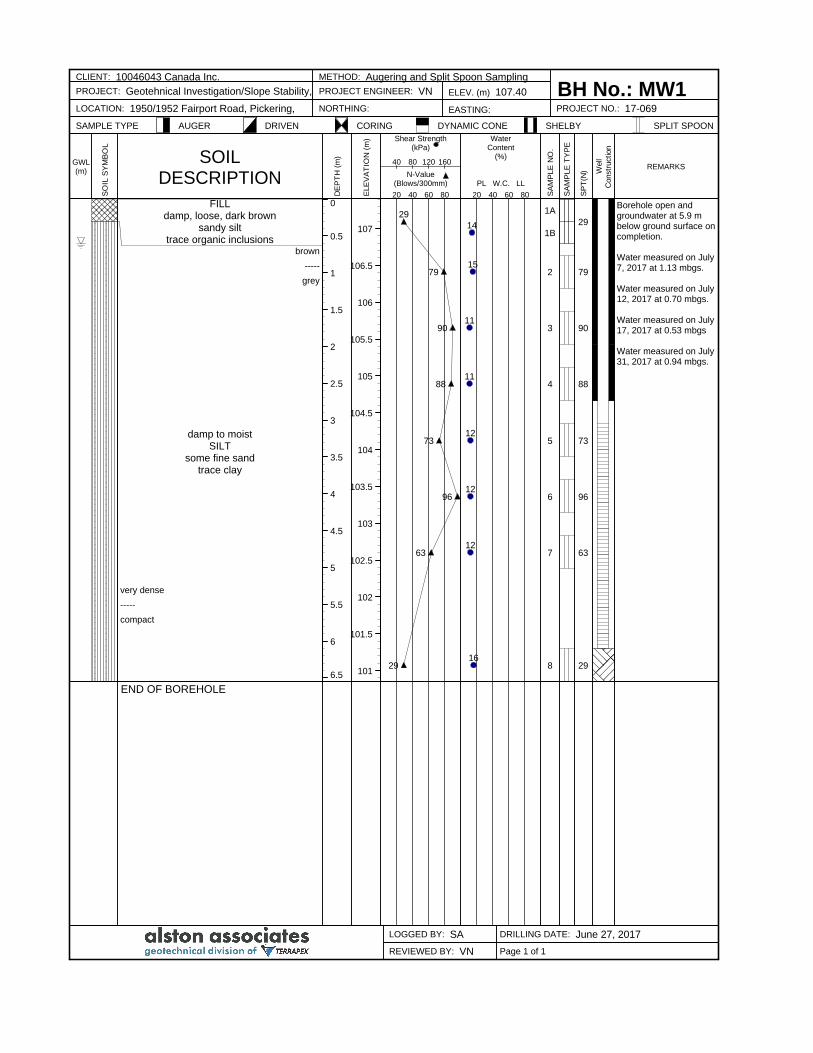
FILLdamp, loose, dark brown
sandy silttrace organic inclusions
brown
-----
grey
damp to moistSILT
some fine sandtrace clay
very dense
-----
compact
END OF BOREHOLE
29
79
90
88
73
96
63
29
14
15
11
11
12
12
12
16
1A
1B
2
3
4
5
6
7
8
29
79
90
88
73
96
63
29
Borehole open andgroundwater at 5.9 mbelow ground surface oncompletion.
Water measured on July7, 2017 at 1.13 mbgs.
Water measured on July12, 2017 at 0.70 mbgs.
Water measured on July17, 2017 at 0.53 mbgs
Water measured on July31, 2017 at 0.94 mbgs.
CLIENT: 10046043 Canada Inc. METHOD: Augering and Split Spoon Sampling
BH No.: MW1PROJECT: Geotehnical Investigation/Slope Stability, PROJECT ENGINEER: VN ELEV. (m) 107.40
LOCATION: 1950/1952 Fairport Road, Pickering, NORTHING: EASTING: PROJECT NO.: 17-069
SAMPLE TYPE AUGER DRIVEN CORING DYNAMIC CONE SHELBY SPLIT SPOON
LOGGED BY: SA DRILLING DATE: June 27, 2017
REVIEWED BY: VN
GWL(m)
SO
IL S
YM
BO
L
SOILDESCRIPTION
DE
PT
H (
m)
ELE
VA
TIO
N (
m) Shear Strength
(kPa)
N-Value(Blows/300mm)
20 40 60 80
40 80 120 160
WaterContent
(%)
PL W.C. LL
20 40 60 80 SA
MP
LE
NO
.
SA
MP
LE
TY
PE
SP
T(N
) Well
Constr
uct
ion
REMARKS
Page 1 of 1
0
0.5
1
1.5
2
2.5
3
3.5
4
4.5
5
5.5
6
6.5
7
7.5
8
105.5
105
104.5
104
103.5
103
102.5
102
101.5
101
100.5
100
99.5
99
98.5
98
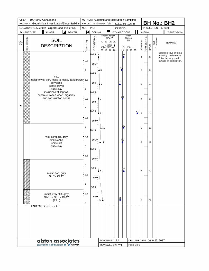
FILLmoist to wet, very loose to loose, dark brown
silty sandsome gravel
trace clayinclusions of asphalt,
concrete, rotten wood, organics,and construction debris
wet, compact, greyfine SANDsome silttrace clay
moist, soft, greySILTY CLAY
moist, very stiff, greySANDY SILTY CLAY
(TILL)
END OF BOREHOLE
3
6
9
3
3
15
11
3
24
26
15
7
20
92
25
19
26
8
1
2
3
4
5
6
7
8
9
3
6
9
3
3
15
11
3
24
Borehole cave-in at 6.1m and groundwater at2.9 m below groundsurface on completion.
CLIENT: 10046043 Canada Inc. METHOD: Augering and Split Spoon Sampling
BH No.: BH2PROJECT: Geotehnical Investigation/Slope Stability, PROJECT ENGINEER: VN ELEV. (m) 105.66
LOCATION: 1950/1952 Fairport Road, Pickering, NORTHING: EASTING: PROJECT NO.: 17-069
SAMPLE TYPE AUGER DRIVEN CORING DYNAMIC CONE SHELBY SPLIT SPOON
LOGGED BY: SA DRILLING DATE: June 27, 2017
REVIEWED BY: VN
GWL(m)
SO
IL S
YM
BO
L
SOILDESCRIPTION
DE
PT
H (
m)
ELE
VA
TIO
N (
m) Shear Strength
(kPa)
N-Value(Blows/300mm)
20 40 60 80
40 80 120 160
WaterContent
(%)
PL W.C. LL
20 40 60 80 SA
MP
LE
NO
.
SA
MP
LE
TY
PE
SP
T(N
) Well
Constr
uct
ion
REMARKS
Page 1 of 1
0
0.5
1
1.5
2
2.5
3
3.5
4
4.5
5
5.5
6
6.5
105.5
105
104.5
104
103.5
103
102.5
102
101.5
101
100.5
100
99.5
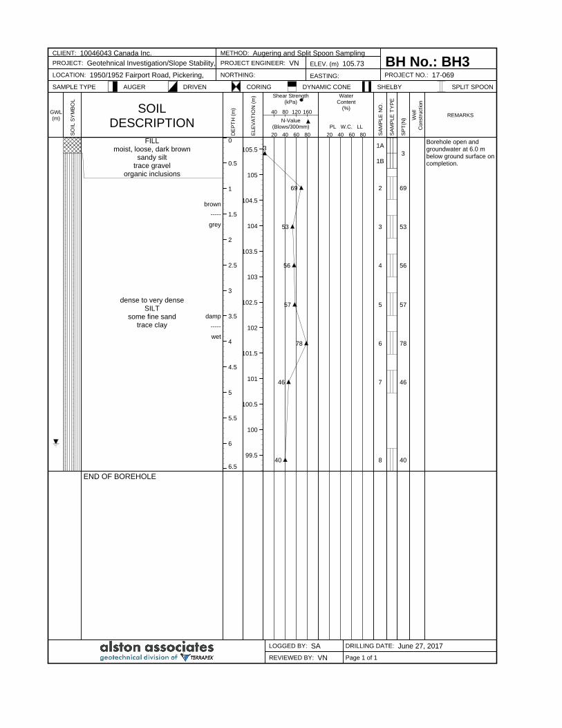
FILLmoist, loose, dark brown
sandy silttrace gravel
organic inclusions
brown
-----
grey
dense to very denseSILT
some fine sandtrace clay
damp
-----
wet
END OF BOREHOLE
3
69
53
56
57
78
46
40
1A
1B
2
3
4
5
6
7
8
3
69
53
56
57
78
46
40
Borehole open andgroundwater at 6.0 mbelow ground surface oncompletion.
CLIENT: 10046043 Canada Inc. METHOD: Augering and Split Spoon Sampling
BH No.: BH3PROJECT: Geotehnical Investigation/Slope Stability, PROJECT ENGINEER: VN ELEV. (m) 105.73
LOCATION: 1950/1952 Fairport Road, Pickering, NORTHING: EASTING: PROJECT NO.: 17-069
SAMPLE TYPE AUGER DRIVEN CORING DYNAMIC CONE SHELBY SPLIT SPOON
LOGGED BY: SA DRILLING DATE: June 27, 2017
REVIEWED BY: VN
GWL(m)
SO
IL S
YM
BO
L
SOILDESCRIPTION
DE
PT
H (
m)
ELE
VA
TIO
N (
m) Shear Strength
(kPa)
N-Value(Blows/300mm)
20 40 60 80
40 80 120 160
WaterContent
(%)
PL W.C. LL
20 40 60 80 SA
MP
LE
NO
.
SA
MP
LE
TY
PE
SP
T(N
) Well
Constr
uct
ion
REMARKS
Page 1 of 1
0
0.5
1
1.5
2
2.5
3
3.5
4
4.5
5
5.5
6
6.5
105
104.5
104
103.5
103
102.5
102
101.5
101
100.5
100
99.5
99
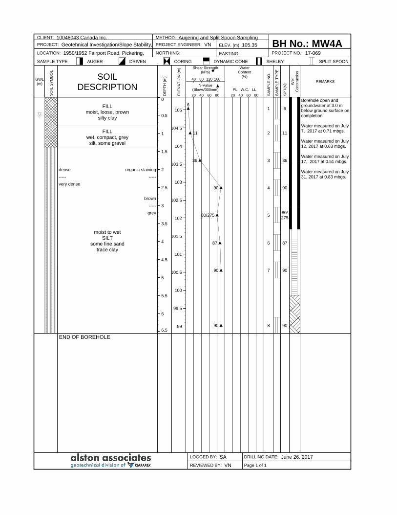
FILLmoist, loose, brown
silty clay
FILLwet, compact, grey
silt, some gravel
dense organic staining
----- -----
very dense
brown
-----
grey
moist to wetSILT
some fine sandtrace clay
END OF BOREHOLE
6
11
36
90
80/275
87
90
90
1
2
3
4
5
6
7
8
6
11
36
90
80/275
87
90
90
Borehole open andgroundwater at 3.0 mbelow ground surface oncompletion.
Water measured on July7, 2017 at 0.71 mbgs.
Water measured on July12, 2017 at 0.63 mbgs.
Water measured on July17, 2017 at 0.51 mbgs.
Water measured on July31, 2017 at 0.83 mbgs.
CLIENT: 10046043 Canada Inc. METHOD: Augering and Split Spoon Sampling
BH No.: MW4APROJECT: Geotehnical Investigation/Slope Stability, PROJECT ENGINEER: VN ELEV. (m) 105.35
LOCATION: 1950/1952 Fairport Road, Pickering, NORTHING: EASTING: PROJECT NO.: 17-069
SAMPLE TYPE AUGER DRIVEN CORING DYNAMIC CONE SHELBY SPLIT SPOON
LOGGED BY: SA DRILLING DATE: June 26, 2017
REVIEWED BY: VN
GWL(m)
SO
IL S
YM
BO
L
SOILDESCRIPTION
DE
PT
H (
m)
ELE
VA
TIO
N (
m) Shear Strength
(kPa)
N-Value(Blows/300mm)
20 40 60 80
40 80 120 160
WaterContent
(%)
PL W.C. LL
20 40 60 80 SA
MP
LE
NO
.
SA
MP
LE
TY
PE
SP
T(N
) Well
Constr
uct
ion
REMARKS
Page 1 of 1
0
0.5
1
1.5
2
2.5
3
3.5
4
4.5
104.5
104
103.5
103
102.5
102
101.5
101
100.5
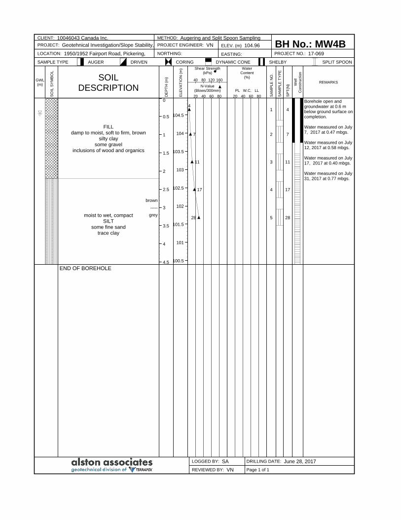
FILLdamp to moist, soft to firm, brown
silty claysome gravel
inclusions of wood and organics
brown
-----
greymoist to wet, compactSILT
some fine sandtrace clay
END OF BOREHOLE
4
7
11
17
28
1
2
3
4
5
4
7
11
17
28
Borehole open andgroundwater at 0.6 mbelow ground surface oncompletion.
Water measured on July7, 2017 at 0.47 mbgs.
Water measured on July12, 2017 at 0.58 mbgs.
Water measured on July17, 2017 at 0.40 mbgs.
Water measured on July31, 2017 at 0.77 mbgs.
CLIENT: 10046043 Canada Inc. METHOD: Augering and Split Spoon Sampling
BH No.: MW4BPROJECT: Geotehnical Investigation/Slope Stability, PROJECT ENGINEER: VN ELEV. (m) 104.96
LOCATION: 1950/1952 Fairport Road, Pickering, NORTHING: EASTING: PROJECT NO.: 17-069
SAMPLE TYPE AUGER DRIVEN CORING DYNAMIC CONE SHELBY SPLIT SPOON
LOGGED BY: SA DRILLING DATE: June 28, 2017
REVIEWED BY: VN
GWL(m)
SO
IL S
YM
BO
L
SOILDESCRIPTION
DE
PT
H (
m)
ELE
VA
TIO
N (
m) Shear Strength
(kPa)
N-Value(Blows/300mm)
20 40 60 80
40 80 120 160
WaterContent
(%)
PL W.C. LL
20 40 60 80 SA
MP
LE
NO
.
SA
MP
LE
TY
PE
SP
T(N
) Well
Constr
uct
ion
REMARKS
Page 1 of 1
0
0.5
1
1.5
2
2.5
3
3.5
4
4.5
5
5.5
6
6.5
105
104.5
104
103.5
103
102.5
102
101.5
101
100.5
100
99.5
99
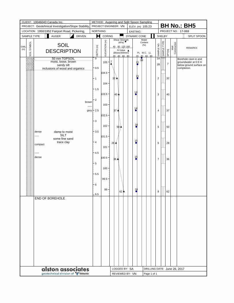
50 mm TOPSOILmoist, loose, brown
sandy siltinclusions of wood and organics
brown
-----
grey
dense damp to moistSILT
some fine sandtrace clay
-----
compact
-----
dense
END OF BOREHOLE
7
32
40
37
50
28
36
62
3921
21
14
14
16
15
15
16
1A
1B
2
3
4
5
6
7
8
7
32
40
37
50
28
36
62
Borehole cave-in andgroundwater at 0.9 mbelow ground surface oncompletion.
CLIENT: 10046043 Canada Inc. METHOD: Augering and Split Spoon Sampling
BH No.: BH5PROJECT: Geotehnical Investigation/Slope Stability, PROJECT ENGINEER: VN ELEV. (m) 105.23
LOCATION: 1950/1952 Fairport Road, Pickering, NORTHING: EASTING: PROJECT NO.: 17-069
SAMPLE TYPE AUGER DRIVEN CORING DYNAMIC CONE SHELBY SPLIT SPOON
LOGGED BY: SA DRILLING DATE: June 26, 2017
REVIEWED BY: VN
GWL(m)
SO
IL S
YM
BO
L
SOILDESCRIPTION
DE
PT
H (
m)
ELE
VA
TIO
N (
m) Shear Strength
(kPa)
N-Value(Blows/300mm)
20 40 60 80
40 80 120 160
WaterContent
(%)
PL W.C. LL
20 40 60 80 SA
MP
LE
NO
.
SA
MP
LE
TY
PE
SP
T(N
) Well
Constr
uct
ion
REMARKS
Page 1 of 1
0
0.5
1
1.5
2
2.5
3
3.5
4
4.5
5
5.5
6
6.5
104.5
104
103.5
103
102.5
102
101.5
101
100.5
100
99.5
99
98.5
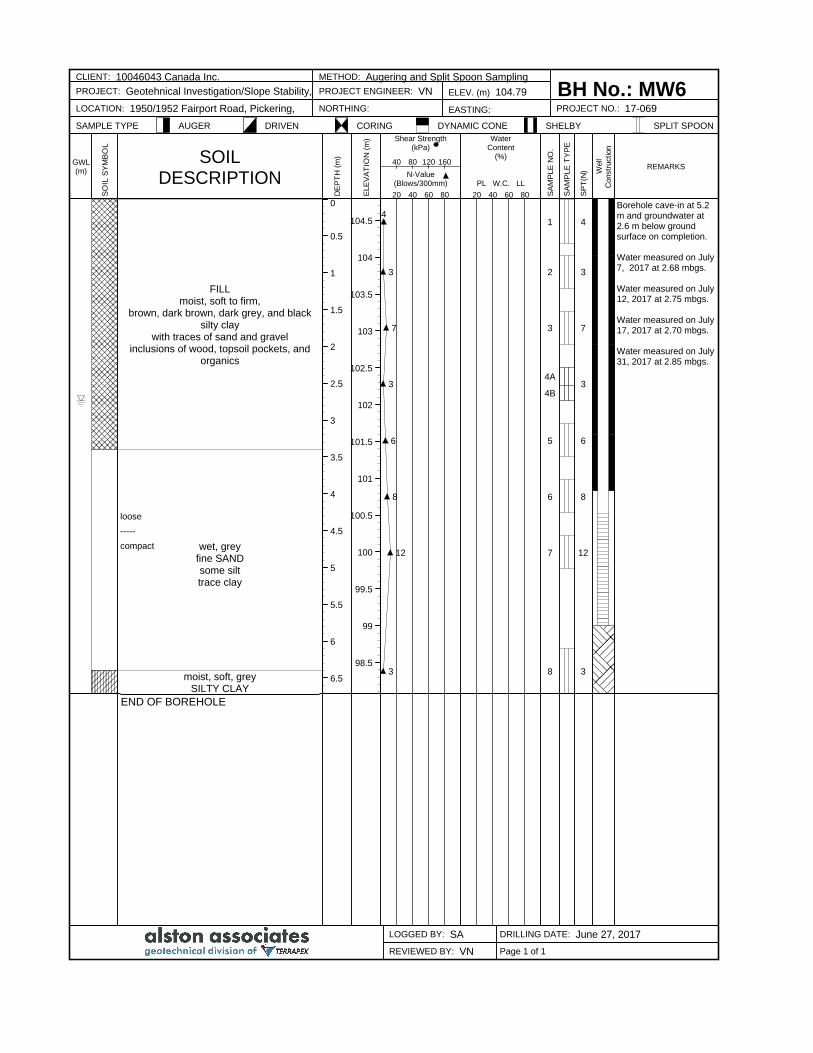
FILLmoist, soft to firm,
brown, dark brown, dark grey, and blacksilty clay
with traces of sand and gravelinclusions of wood, topsoil pockets, and
organics
loose
-----
compact wet, greyfine SANDsome silttrace clay
moist, soft, greySILTY CLAY
END OF BOREHOLE
4
3
7
3
6
8
12
3
1
2
3
4A
4B
5
6
7
8
4
3
7
3
6
8
12
3
Borehole cave-in at 5.2m and groundwater at2.6 m below groundsurface on completion.
Water measured on July7, 2017 at 2.68 mbgs.
Water measured on July12, 2017 at 2.75 mbgs.
Water measured on July17, 2017 at 2.70 mbgs.
Water measured on July31, 2017 at 2.85 mbgs.
CLIENT: 10046043 Canada Inc. METHOD: Augering and Split Spoon Sampling
BH No.: MW6PROJECT: Geotehnical Investigation/Slope Stability, PROJECT ENGINEER: VN ELEV. (m) 104.79
LOCATION: 1950/1952 Fairport Road, Pickering, NORTHING: EASTING: PROJECT NO.: 17-069
SAMPLE TYPE AUGER DRIVEN CORING DYNAMIC CONE SHELBY SPLIT SPOON
LOGGED BY: SA DRILLING DATE: June 27, 2017
REVIEWED BY: VN
GWL(m)
SO
IL S
YM
BO
L
SOILDESCRIPTION
DE
PT
H (
m)
ELE
VA
TIO
N (
m) Shear Strength
(kPa)
N-Value(Blows/300mm)
20 40 60 80
40 80 120 160
WaterContent
(%)
PL W.C. LL
20 40 60 80 SA
MP
LE
NO
.
SA
MP
LE
TY
PE
SP
T(N
) Well
Constr
uct
ion
REMARKS
Page 1 of 1
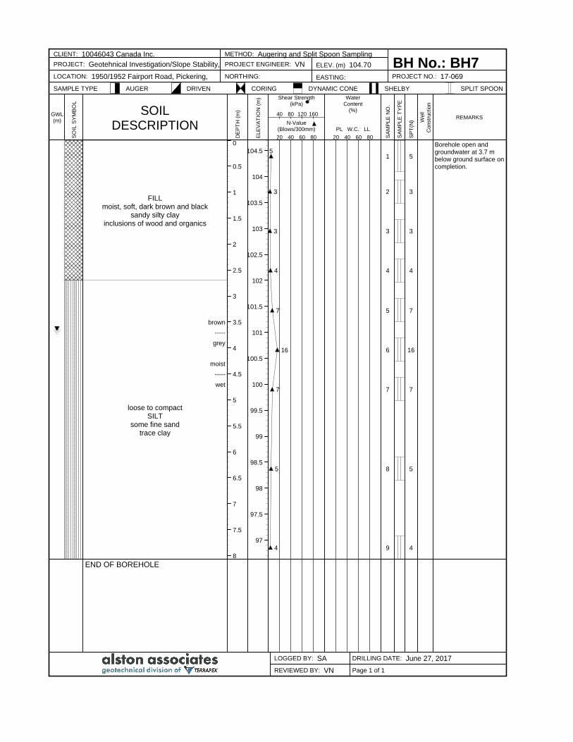
0
0.5
1
1.5
2
2.5
3
3.5
4
4.5
5
5.5
6
6.5
7
7.5
8
104.5
104
103.5
103
102.5
102
101.5
101
100.5
100
99.5
99
98.5
98
97.5
97
FILLmoist, soft, dark brown and black
sandy silty clayinclusions of wood and organics
brown
-----
grey
moist
-----
wet
loose to compactSILT
some fine sandtrace clay
END OF BOREHOLE
5
3
3
4
7
16
7
5
4
1
2
3
4
5
6
7
8
9
5
3
3
4
7
16
7
5
4
Borehole open andgroundwater at 3.7 mbelow ground surface oncompletion.
CLIENT: 10046043 Canada Inc. METHOD: Augering and Split Spoon Sampling
BH No.: BH7PROJECT: Geotehnical Investigation/Slope Stability, PROJECT ENGINEER: VN ELEV. (m) 104.70
LOCATION: 1950/1952 Fairport Road, Pickering, NORTHING: EASTING: PROJECT NO.: 17-069
SAMPLE TYPE AUGER DRIVEN CORING DYNAMIC CONE SHELBY SPLIT SPOON
LOGGED BY: SA DRILLING DATE: June 27, 2017
REVIEWED BY: VN
GWL(m)
SO
IL S
YM
BO
L
SOILDESCRIPTION
DE
PT
H (
m)
ELE
VA
TIO
N (
m) Shear Strength
(kPa)
N-Value(Blows/300mm)
20 40 60 80
40 80 120 160
WaterContent
(%)
PL W.C. LL
20 40 60 80 SA
MP
LE
NO
.
SA
MP
LE
TY
PE
SP
T(N
) Well
Constr
uct
ion
REMARKS
Page 1 of 1
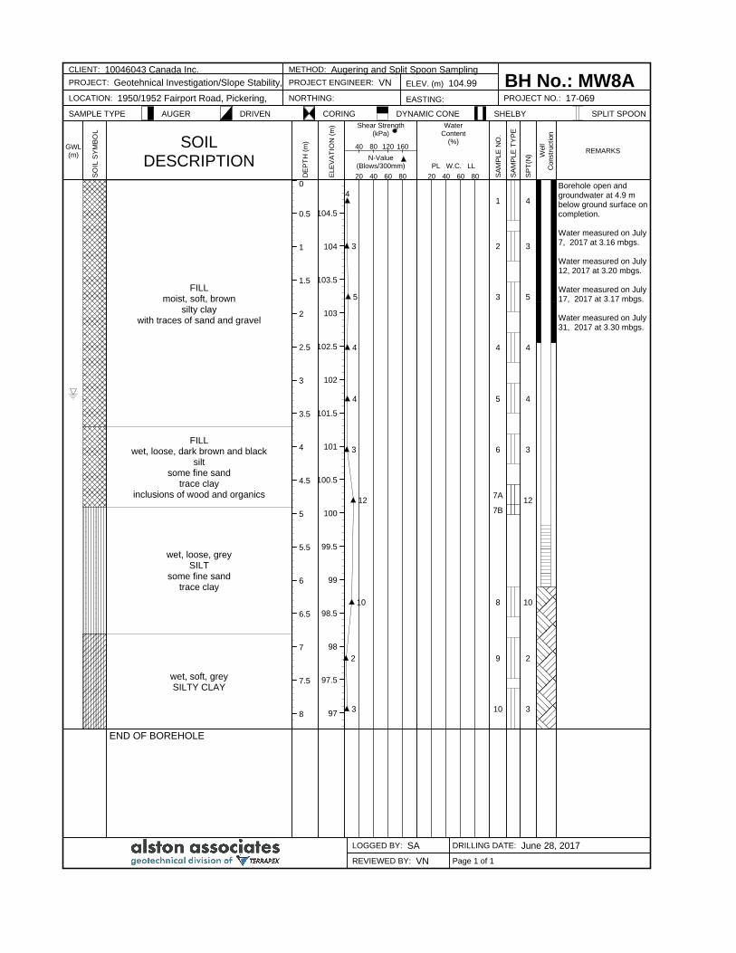
0
0.5
1
1.5
2
2.5
3
3.5
4
4.5
5
5.5
6
6.5
7
7.5
8
104.5
104
103.5
103
102.5
102
101.5
101
100.5
100
99.5
99
98.5
98
97.5
97
FILLmoist, soft, brown
silty claywith traces of sand and gravel
FILLwet, loose, dark brown and black
siltsome fine sand
trace clayinclusions of wood and organics
wet, loose, greySILT
some fine sandtrace clay
wet, soft, greySILTY CLAY
END OF BOREHOLE
4
3
5
4
4
3
12
10
2
3
1
2
3
4
5
6
7A
7B
8
9
10
4
3
5
4
4
3
12
10
2
3
Borehole open andgroundwater at 4.9 mbelow ground surface oncompletion.
Water measured on July7, 2017 at 3.16 mbgs.
Water measured on July12, 2017 at 3.20 mbgs.
Water measured on July17, 2017 at 3.17 mbgs.
Water measured on July31, 2017 at 3.30 mbgs.
CLIENT: 10046043 Canada Inc. METHOD: Augering and Split Spoon Sampling
BH No.: MW8APROJECT: Geotehnical Investigation/Slope Stability, PROJECT ENGINEER: VN ELEV. (m) 104.99
LOCATION: 1950/1952 Fairport Road, Pickering, NORTHING: EASTING: PROJECT NO.: 17-069
SAMPLE TYPE AUGER DRIVEN CORING DYNAMIC CONE SHELBY SPLIT SPOON
LOGGED BY: SA DRILLING DATE: June 28, 2017
REVIEWED BY: VN
GWL(m)
SO
IL S
YM
BO
L
SOILDESCRIPTION
DE
PT
H (
m)
ELE
VA
TIO
N (
m) Shear Strength
(kPa)
N-Value(Blows/300mm)
20 40 60 80
40 80 120 160
WaterContent
(%)
PL W.C. LL
20 40 60 80 SA
MP
LE
NO
.
SA
MP
LE
TY
PE
SP
T(N
) Well
Constr
uct
ion
REMARKS
Page 1 of 1
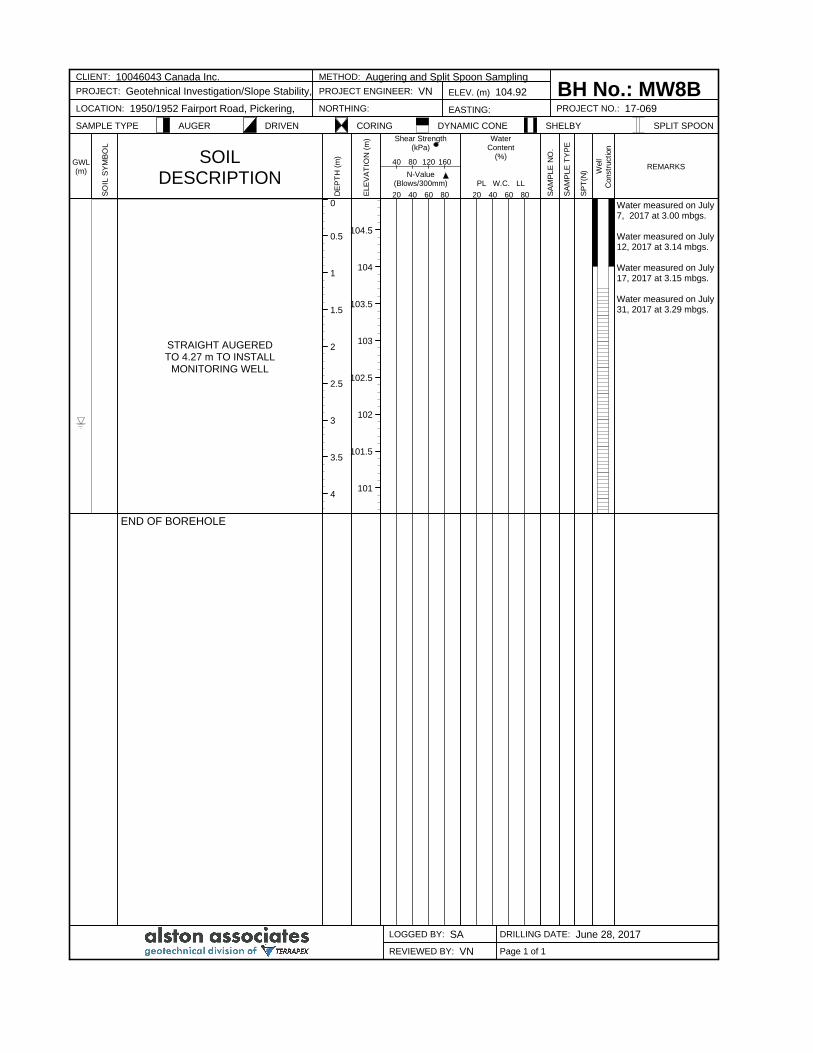
0
0.5
1
1.5
2
2.5
3
3.5
4
104.5
104
103.5
103
102.5
102
101.5
101
STRAIGHT AUGEREDTO 4.27 m TO INSTALL
MONITORING WELL
END OF BOREHOLE
Water measured on July7, 2017 at 3.00 mbgs.
Water measured on July12, 2017 at 3.14 mbgs.
Water measured on July17, 2017 at 3.15 mbgs.
Water measured on July31, 2017 at 3.29 mbgs.
CLIENT: 10046043 Canada Inc. METHOD: Augering and Split Spoon Sampling
BH No.: MW8BPROJECT: Geotehnical Investigation/Slope Stability, PROJECT ENGINEER: VN ELEV. (m) 104.92
LOCATION: 1950/1952 Fairport Road, Pickering, NORTHING: EASTING: PROJECT NO.: 17-069
SAMPLE TYPE AUGER DRIVEN CORING DYNAMIC CONE SHELBY SPLIT SPOON
LOGGED BY: SA DRILLING DATE: June 28, 2017
REVIEWED BY: VN
GWL(m)
SO
IL S
YM
BO
L
SOILDESCRIPTION
DE
PT
H (
m)
ELE
VA
TIO
N (
m) Shear Strength
(kPa)
N-Value(Blows/300mm)
20 40 60 80
40 80 120 160
WaterContent
(%)
PL W.C. LL
20 40 60 80 SA
MP
LE
NO
.
SA
MP
LE
TY
PE
SP
T(N
) Well
Constr
uct
ion
REMARKS
Page 1 of 1
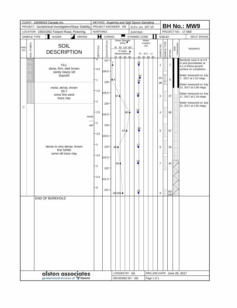
0
0.5
1
1.5
2
2.5
3
3.5
4
4.5
5
5.5
6
107
106.5
106
105.5
105
104.5
104
103.5
103
102.5
102
101.5
101
FILLdamp, firm, dark brown
sandy clayey silt(topsoil)
moist, dense, brownSILT
some fine sandtrace clay
moist
-----
wet
dense to very dense, brownfine SAND
some silt trace clay
END OF BOREHOLE
7
5
37
80
67
30
40
50/150
19
24
19
16
15
20
17
16
18
1
2A
2B
3
4
5
6
7
8
7
5
37
80
67
30
40
50/150
Borehole cave-in at 4.9m and groundwater at4.1 m below groundsurface on completion.
Water measured on July7, 2017 at 1.31 mbgs.
Water measured on July12, 2017 at 2.09 mbgs.
Water measured on July17, 2017 at 2.19 mbgs.
Water measured on July31, 2017 at 2.65 mbgs.
CLIENT: 10046043 Canada Inc. METHOD: Augering and Split Spoon Sampling
BH No.: MW9PROJECT: Geotehnical Investigation/Slope Stability, PROJECT ENGINEER: VN ELEV. (m) 107.10
LOCATION: 1950/1952 Fairport Road, Pickering, NORTHING: EASTING: PROJECT NO.: 17-069
SAMPLE TYPE AUGER DRIVEN CORING DYNAMIC CONE SHELBY SPLIT SPOON
LOGGED BY: SA DRILLING DATE: June 26, 2017
REVIEWED BY: VN
GWL(m)
SO
IL S
YM
BO
L
SOILDESCRIPTION
DE
PT
H (
m)
ELE
VA
TIO
N (
m) Shear Strength
(kPa)
N-Value(Blows/300mm)
20 40 60 80
40 80 120 160
WaterContent
(%)
PL W.C. LL
20 40 60 80 SA
MP
LE
NO
.
SA
MP
LE
TY
PE
SP
T(N
) Well
Constr
uct
ion
REMARKS
Page 1 of 1
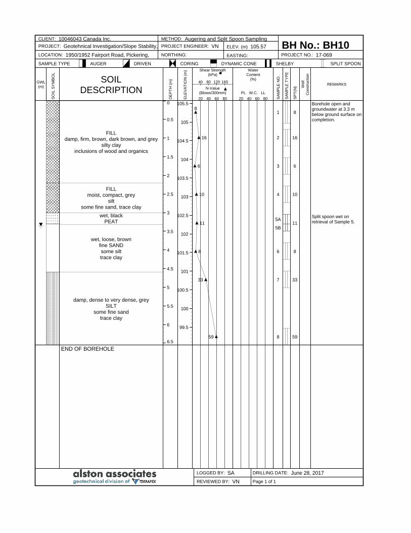
0
0.5
1
1.5
2
2.5
3
3.5
4
4.5
5
5.5
6
6.5
105.5
105
104.5
104
103.5
103
102.5
102
101.5
101
100.5
100
99.5
FILLdamp, firm, brown, dark brown, and grey
silty clayinclusions of wood and organics
FILLmoist, compact, grey
siltsome fine sand, trace clay
wet, blackPEAT
wet, loose, brownfine SANDsome silttrace clay
damp, dense to very dense, greySILT
some fine sandtrace clay
END OF BOREHOLE
8
16
6
10
11
8
33
59
1
2
3
4
5A
5B
6
7
8
8
16
6
10
11
8
33
59
Borehole open andgroundwater at 3.3 mbelow ground surface oncompletion.
Split spoon wet onretrieval of Sample 5.
CLIENT: 10046043 Canada Inc. METHOD: Augering and Split Spoon Sampling
BH No.: BH10PROJECT: Geotehnical Investigation/Slope Stability, PROJECT ENGINEER: VN ELEV. (m) 105.57
LOCATION: 1950/1952 Fairport Road, Pickering, NORTHING: EASTING: PROJECT NO.: 17-069
SAMPLE TYPE AUGER DRIVEN CORING DYNAMIC CONE SHELBY SPLIT SPOON
LOGGED BY: SA DRILLING DATE: June 28, 2017
REVIEWED BY: VN
GWL(m)
SO
IL S
YM
BO
L
SOILDESCRIPTION
DE
PT
H (
m)
ELE
VA
TIO
N (
m) Shear Strength
(kPa)
N-Value(Blows/300mm)
20 40 60 80
40 80 120 160
WaterContent
(%)
PL W.C. LL
20 40 60 80 SA
MP
LE
NO
.
SA
MP
LE
TY
PE
SP
T(N
) Well
Constr
uct
ion
REMARKS
Page 1 of 1
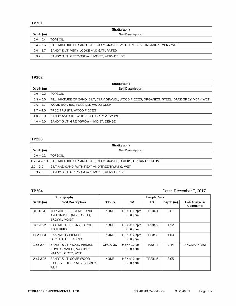
TERRAPEX ENVIRONMENTAL LTD. 10046043 Canada Inc. CT2543.01 Page 1 of 5
TP201
Stratigraphy
Depth (m) Soil Description
0.0 – 0.4 TOPSOIL,
0.4 – 2.6 FILL, MIXTURE OF SAND, SILT, CLAY GRAVEL, WOOD PIECES, ORGANICS, VERY WET
2.6 – 3.7 SANDY SILT, VERY LOOSE AND SATURATED
3.7 + SANDY SILT, GREY-BROWN, MOIST, VERY DENSE
TP202
Stratigraphy
Depth (m) Soil Description
0.0 – 0.3 TOPSOIL,
0.3 – 2.6 FILL, MIXTURE OF SAND, SILT, CLAY GRAVEL, WOOD PIECES, ORGANICS, STEEL, DARK GREY, VERY WET
2.6 – 2.7 WOOD BOARDS, POSSIBLE WOOD DECK
2.7 – 4.0 TREE TRUNKS, WOOD PIECES
4.0 – 5.0 SANDY AND SILT WITH PEAT, GREY VERY WET
4.0 – 5.0 SANDY SILT, GREY-BROWN, MOIST, DENSE
TP203
Stratigraphy
Depth (m) Soil Description
0.0 – 0.2 TOPSOIL,
0.2 - 4 – 2.0 FILL, MIXTURE OF SAND, SILT, CLAY GRAVEL, BRICKS, ORGANICS, MOIST
2.0 – 3.2 SILT AND SAND, WITH PEAT AND TREE TRUNKS, WET
3.7 + SANDY SILT, GREY-BROWN, MOIST, VERY DENSE
TP204 Date: December 7, 2017
Stratigraphy Sample Data
Depth (m) Soil Description Odours SV I.D. Depth (m) Lab Analysis/ Comments
0.0-0.61 TOPSOIL, SILT, CLAY, SAND
AND GRAVEL (MIXED FILL),
BROWN, MOIST
NONE HEX <10 ppm
IBL 0 ppm
TP204-1 0.61
0.61-1.22 SAA, METAL REBAR, LARGE
BOULDERS
NONE HEX <10 ppm
IBL 0 ppm
TP204-2 1.22
1.22-1.83 SAA, WOOD PIECES,
GEOTEXTILE FABRIC
NONE HEX <10 ppm
IBL 0 ppm
TP204-3 1.83
1.83-2.44 SANDY SILT, WOOD PIECES,
SOME GRAVEL (POSSIBLY
NATIVE), GREY, WET
ORGANIC HEX <10 ppm
IBL 0 ppm
TP204-4 2.44 PHCs/PAH/M&I
2.44-3.05 SANDY SILT, SOME WOOD
PIECES, SOFT (NATIVE), GREY,
WET
NONE HEX <10 ppm
IBL 0 ppm
TP204-5 3.05
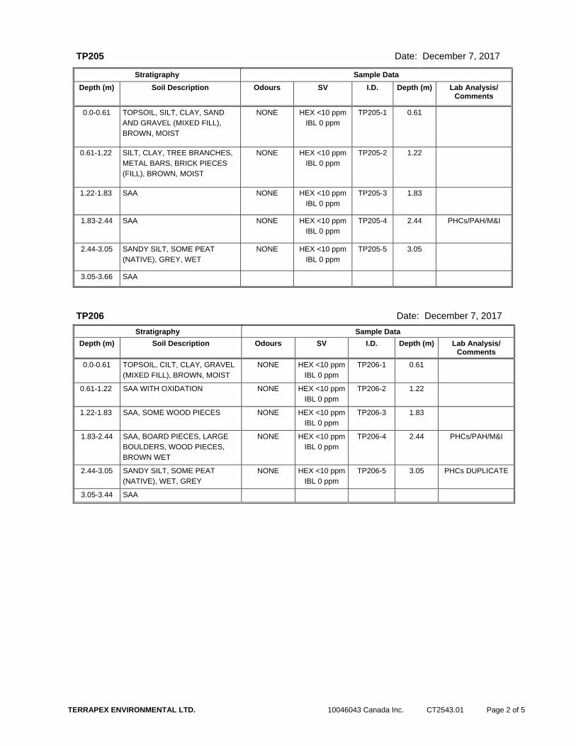
TERRAPEX ENVIRONMENTAL LTD. 10046043 Canada Inc. CT2543.01 Page 2 of 5
TP205 Date: December 7, 2017
Stratigraphy Sample Data
Depth (m) Soil Description Odours SV I.D. Depth (m) Lab Analysis/ Comments
0.0-0.61 TOPSOIL, SILT, CLAY, SAND
AND GRAVEL (MIXED FILL),
BROWN, MOIST
NONE HEX <10 ppm
IBL 0 ppm
TP205-1 0.61
0.61-1.22 SILT, CLAY, TREE BRANCHES,
METAL BARS, BRICK PIECES
(FILL), BROWN, MOIST
NONE HEX <10 ppm
IBL 0 ppm
TP205-2 1.22
1.22-1.83 SAA NONE HEX <10 ppm
IBL 0 ppm
TP205-3 1.83
1.83-2.44 SAA NONE HEX <10 ppm
IBL 0 ppm
TP205-4 2.44 PHCs/PAH/M&I
2.44-3.05 SANDY SILT, SOME PEAT
(NATIVE), GREY, WET
NONE HEX <10 ppm
IBL 0 ppm
TP205-5 3.05
3.05-3.66 SAA
TP206 Date: December 7, 2017
Stratigraphy Sample Data
Depth (m) Soil Description Odours SV I.D. Depth (m) Lab Analysis/ Comments
0.0-0.61 TOPSOIL, CILT, CLAY, GRAVEL
(MIXED FILL), BROWN, MOIST
NONE HEX <10 ppm
IBL 0 ppm
TP206-1 0.61
0.61-1.22 SAA WITH OXIDATION NONE HEX <10 ppm
IBL 0 ppm
TP206-2 1.22
1.22-1.83 SAA, SOME WOOD PIECES NONE HEX <10 ppm
IBL 0 ppm
TP206-3 1.83
1.83-2.44 SAA, BOARD PIECES, LARGE
BOULDERS, WOOD PIECES,
BROWN WET
NONE HEX <10 ppm
IBL 0 ppm
TP206-4 2.44 PHCs/PAH/M&I
2.44-3.05 SANDY SILT, SOME PEAT
(NATIVE), WET, GREY
NONE HEX <10 ppm
IBL 0 ppm
TP206-5 3.05 PHCs DUPLICATE
3.05-3.44 SAA

TERRAPEX ENVIRONMENTAL LTD. 10046043 Canada Inc. CT2543.01 Page 3 of 5
TP207 Date: December 7, 2017
Stratigraphy Sample Data
Depth (m) Soil Description Odours SV I.D. Depth (m) Lab Analysis/ Comments
0.0-0.61 TOPSOIL, SILT, CLAY, GRAVEL
(MIXED FILL), BROWN, MOIST
NONE HEX <10 ppm
IBL 0 ppm
TP207-1 0.61
0.61-1.22 SAA NONE HEX <10 ppm
IBL 0 ppm
TP207-2 1.22
1.22-1.83 SAA. WOOD PIECES, ROOFING
MATERIAL, ASPHALT, METAL
PIECES
TAR HEX 5 ppm
IBL 0 ppm
TP207-3 1.83 PHCs/PAH/M&I
1.83-3.05 SAA, WITH SAWDUST NONE HEX <10 ppm
IBL 0 ppm
TP207-4 3.05
3.05-3.44 SANDY SILT (NATIVE), GREY,
MOIST
NONE HEX <10 ppm
IBL 0 ppm
TP207-5 3.44
3.44-4.27 SAA
TP208 Date: December 7, 2017
Stratigraphy Sample Data
Depth (m) Soil Description Odours SV I.D. Depth (m) Lab Analysis/ Comments
0.0-0.61 TOPSOIL, SILT, CLAY, SOME
GRAVEL (MIXED FILL), BROWN,
MOIST
NONE HEX <10 ppm
IBL 0 ppm
TP208-1 0.61
0.61-1.22 SAA NONE HEX <10 ppm
IBL 0 ppm
TP208-2 1.22
1.22-1.83 MIXED FILL TO SANDY SILT
(POSSIBLY NATIVE), GREY
MOIST
NONE HEX <10 ppm
IBL 0 ppm
TP208-3 1.83
1.83-3.05 SILT, CLAY, GRAVEL,
SAWDUST, WOOD PIECES
(MIXED FILL)
NONE HEX <10 ppm
IBL 0 ppm
TP208-4 3.05 PHCs/PAH/M&I
3.05-3.66 SANDY SILT, WOOD PIECES,
ROOTS (NATIVE) GREY, MOIST
NONE HEX <10 ppm
IBL 0 ppm
TP208-5 3.66
TP209 Date: March 28, 2018
Stratigraphy Sample Data
Depth (m) Soil Description Odours SV I.D. Depth (m) Lab Analysis/ Comments
0.0-0.20 TOPSOIL,
0.20-2.00 MIXED FILL, BROWN AND GREY
WITH SOME ORGANICS, MOIST
2.00-3.50 MIXED FILL, GREY
WITH SOME ORGANICS, MOIST
3.50 – 3.80 PEAT, BLACK, WET
3.80-4.00 SANDY SILT (NATIVE), GREY,
MOIST

TERRAPEX ENVIRONMENTAL LTD. 10046043 Canada Inc. CT2543.01 Page 4 of 5
TP210 Date: March 28, 2018
Stratigraphy Sample Data
Depth (m) Soil Description Odours SV I.D. Depth (m) Lab Analysis/ Comments
0.0-0.15 TOPSOIL,
0.15-2.00 MIXED FILL, BROWN AND GREY
WITH SOME ORGANICS, MOIST,
2.00-3.00 MIXED FILL, GREY, WITH SOME
ORGANICS, MOIST,
3.00 + SANDY SILT (NATIVE), GREY,
MOIST
TP211 Date: March 28, 2018
Stratigraphy Sample Data
Depth (m) Soil Description Odours SV I.D. Depth (m) Lab Analysis/ Comments
0.0-0.15 TOPSOIL,
0.15-3.00 MIXED FILL, BROWN WITH SOME
ORGANICS, WITH INCLUSIONS
OF ASPHALTIC CONCRETE,
WELDED WIRE MESH, PLASTIC
PIPE, ETC., MOIST,
3.00 + SANDY SILT (NATIVE), GREY,
MOIST
TP212 Date: March 28, 2018
Stratigraphy Sample Data
Depth (m) Soil Description Odours SV I.D. Depth (m) Lab Analysis/ Comments
0.0-0.20 TOPSOIL,
0.20-3.00 MIXED FILL, WITH TREE
BRANCHES AND ROOTS,
SATURATED. WATER DRAINING
INTO TEST PIT FROM
SOUTHEAST CORNER OF PIT.
WATER LEVEL AT ABOUT 2 M
BELOW GRADE.
3.00 + POSSIBLE NATIVE SOIL, COULD
NOT BE CONFIRMED DUE TO
INFLUX OF WATER AND
SLOUGHING OF THE WALLS OF
THE TEST PIT.
TP213
Date:
March 28, 2018
Stratigraphy Sample Data
Depth (m) Soil Description Odours SV I.D. Depth (m) Lab Analysis/ Comments
0.0-0.20 TOPSOIL,
0.20-3.00 MIXED FILL, WITH TREE
BRANCHES AND ROOTS,

TERRAPEX ENVIRONMENTAL LTD. 10046043 Canada Inc. CT2543.01 Page 5 of 5
TP213
Date:
March 28, 2018
Stratigraphy Sample Data
Depth (m) Soil Description Odours SV I.D. Depth (m) Lab Analysis/ Comments
SATURATED, WATER LEVEL AT
ABOUT 2 M BELOW GRADE.
3.00 + COULD NOT BE DETERMINED
DUE TO INFLUX OF WATER AND
SLOUGHING OF THE WALLS OF
THE TEST PIT.

alston associates Reference 17-069
A division of Terrapex Environmental Ltd. April 2019
GEOTECHNICAL INVESTIGATION REPORT
1950 AND 1952 FAIRPORT ROAD, PICKERING, ONTARIO
10046043 CANADA INC.
APPENDIX D LABORATORY TEST RESULTS
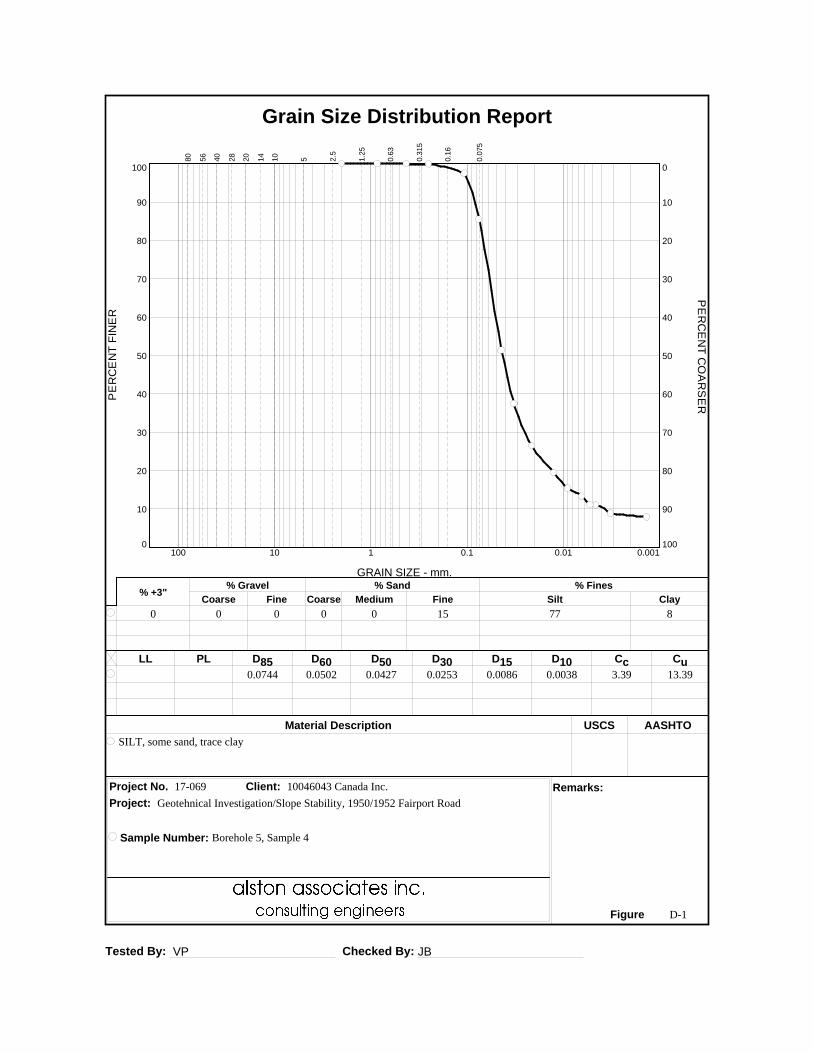
Tested By: VP Checked By: JB
LL PL D85 D60 D50 D30 D15 D10 Cc Cu
Material Description USCS AASHTO
Project No. Client: Remarks:
Project:
Sample Number: Borehole 5, Sample 4
Figure
0.0744 0.0502 0.0427 0.0253 0.0086 0.0038 3.39 13.39
SILT, some sand, trace clay
17-069 10046043 Canada Inc.
D-1
PE
RC
EN
T F
INE
R
0
10
20
30
40
50
60
70
80
90
100
PE
RC
EN
T C
OA
RS
ER
100
90
80
70
60
50
40
30
20
10
0
GRAIN SIZE - mm.
0.0010.010.1110100
% +3"Coarse
% Gravel
Fine Coarse Medium
% Sand
Fine Silt
% Fines
Clay
0 0 0 0 0 15 77 8
80
56
40
28
20
14
10
5 2.5
1.2
5
0.6
3
0.3
15
0.1
6
0.0
75
Grain Size Distribution Report
Geotehnical Investigation/Slope Stability, 1950/1952 Fairport Road

Tested By: VP Checked By: JB
LL PL D85 D60 D50 D30 D15 D10 Cc Cu
Material Description USCS AASHTO
Project No. Client: Remarks:
Project:
Sample Number: Borehole 5, Sample 7
Figure
0.0682 0.0444 0.0371 0.0198 0.0063 0.0027 3.27 16.43
SILT, some sand, trace clay
17-069 10046043 Canada Inc.
D-2
PE
RC
EN
T F
INE
R
0
10
20
30
40
50
60
70
80
90
100
PE
RC
EN
T C
OA
RS
ER
100
90
80
70
60
50
40
30
20
10
0
GRAIN SIZE - mm.
0.0010.010.1110100
% +3"Coarse
% Gravel
Fine Coarse Medium
% Sand
Fine Silt
% Fines
Clay
0 0 0 0 0 11 80 9
80
56
40
28
20
14
10
5 2.5
1.2
5
0.6
3
0.3
15
0.1
6
0.0
75
Grain Size Distribution Report
Geotehnical Investigation/Slope Stability, 1950/1952 Fairport Road
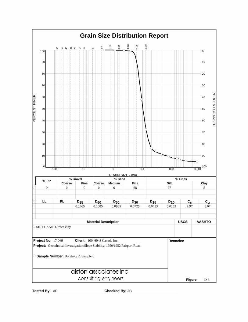
Tested By: VP Checked By: JB
LL PL D85 D60 D50 D30 D15 D10 Cc Cu
Material Description USCS AASHTO
Project No. Client: Remarks:
Project:
Sample Number: Borehole 2, Sample 6
Figure
0.1465 0.1085 0.0965 0.0725 0.0453 0.0163 2.97 6.67
SILTY SAND, trace clay
17-069 10046043 Canada Inc.
D-3
PE
RC
EN
T F
INE
R
0
10
20
30
40
50
60
70
80
90
100
PE
RC
EN
T C
OA
RS
ER
100
90
80
70
60
50
40
30
20
10
0
GRAIN SIZE - mm.
0.0010.010.1110100
% +3"Coarse
% Gravel
Fine Coarse Medium
% Sand
Fine Silt
% Fines
Clay
0 0 0 0 0 68 27 5
80
56
40
28
20
14
10
5 2.5
1.2
5
0.6
3
0.3
15
0.1
6
0.0
75
Grain Size Distribution Report
Geotehnical Investigation/Slope Stability, 1950/1952 Fairport Road
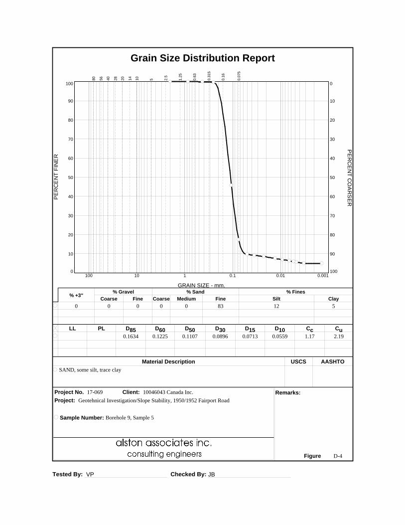
Tested By: VP Checked By: JB
LL PL D85 D60 D50 D30 D15 D10 Cc Cu
Material Description USCS AASHTO
Project No. Client: Remarks:
Project:
Sample Number: Borehole 9, Sample 5
Figure
0.1634 0.1225 0.1107 0.0896 0.0713 0.0559 1.17 2.19
SAND, some silt, trace clay
17-069 10046043 Canada Inc.
D-4
PE
RC
EN
T F
INE
R
0
10
20
30
40
50
60
70
80
90
100
PE
RC
EN
T C
OA
RS
ER
100
90
80
70
60
50
40
30
20
10
0
GRAIN SIZE - mm.
0.0010.010.1110100
% +3"Coarse
% Gravel
Fine Coarse Medium
% Sand
Fine Silt
% Fines
Clay
0 0 0 0 0 83 12 5
80
56
40
28
20
14
10
5 2.5
1.2
5
0.6
3
0.3
15
0.1
6
0.0
75
Grain Size Distribution Report
Geotehnical Investigation/Slope Stability, 1950/1952 Fairport Road
alston associates Reference 17-069
A division of Terrapex Environmental Ltd. April 2019
GEOTECHNICAL INVESTIGATION REPORT
1950 AND 1952 FAIRPORT ROAD, PICKERING, ONTARIO
10046043 CANADA INC.
APPENDIX E TYPICAL PERIMETER DRAINAGE SYSTEM
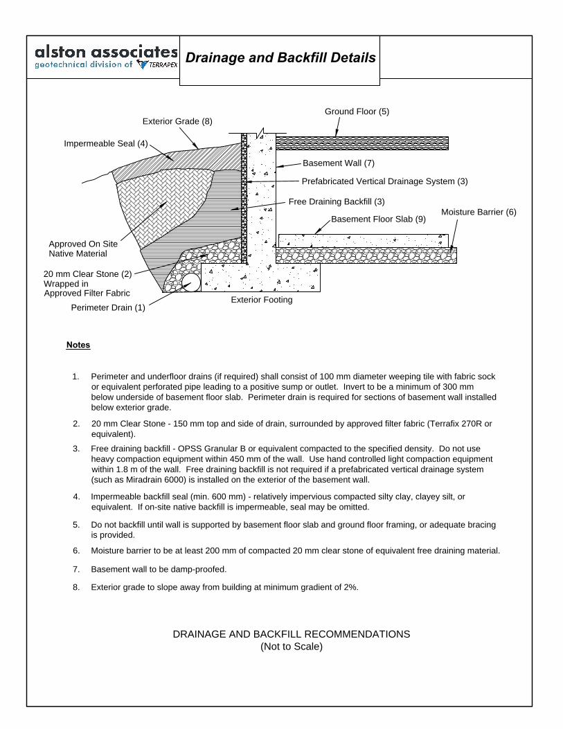
20 mm Clear Stone (2)
Moisture Barrier (6)
Notes
4. Impermeable backfill seal (min. 600 mm) - relatively impervious compacted silty clay, clayey silt, or
equivalent. If on-site native backfill is impermeable, seal may be omitted.
1. Perimeter and underfloor drains (if required) shall consist of 100 mm diameter weeping tile with fabric sock
or equivalent perforated pipe leading to a positive sump or outlet. Invert to be a minimum of 300 mm
below underside of basement floor slab. Perimeter drain is required for sections of basement wall installed
below exterior grade.
3. Free draining backfill - OPSS Granular B or equivalent compacted to the specified density. Do not use
heavy compaction equipment within 450 mm of the wall. Use hand controlled light compaction equipment
within 1.8 m of the wall. Free draining backfill is not required if a prefabricated vertical drainage system
(such as Miradrain 6000) is installed on the exterior of the basement wall.
2. 20 mm Clear Stone - 150 mm top and side of drain, surrounded by approved filter fabric (Terrafix 270R or
equivalent).
Exterior Footing
5. Do not backfill until wall is supported by basement floor slab and ground floor framing, or adequate bracing
is provided.
Basement Floor Slab (9)
Free Draining Backfill (3)
Prefabricated Vertical Drainage System (3)
8. Exterior grade to slope away from building at minimum gradient of 2%.
7. Basement wall to be damp-proofed.
Basement Wall (7)
Ground Floor (5)
Exterior Grade (8)
Impermeable Seal (4)
Native Material
Perimeter Drain (1)
Approved On Site
6. Moisture barrier to be at least 200 mm of compacted 20 mm clear stone of equivalent free draining material.
DRAINAGE AND BACKFILL RECOMMENDATIONS
(Not to Scale)
Wrapped in
Approved Filter Fabric
Drainage and Backfill Details

alston associates Reference 17-069
A division of Terrapex Environmental Ltd. April 2019
GEOTECHNICAL INVESTIGATION REPORT
1950 AND 1952 FAIRPORT ROAD, PICKERING, ONTARIO
10046043 CANADA INC.
APPENDIX F CERTIFICATE OF CHEMICAL ANALYSES
CLIENT NAME: ALSTON ASSOCIATES90 SCARSDALE RDTORONTO, ON M3B2R7 (905) 474-5265
5835 COOPERS AVENUEMISSISSAUGA, ONTARIO
CANADA L4Z 1Y2TEL (905)712-5100FAX (905)712-5122
http://www.agatlabs.com
Amanjot Bhela, Inorganic CoordinatorSOIL ANALYSIS REVIEWED BY:
DATE REPORTED:
PAGES (INCLUDING COVER): 5
Jul 11, 2017
VERSION*: 1
Should you require any information regarding this analysis please contact your client services representative at (905) 712-5100
17T234868AGAT WORK ORDER:
ATTENTION TO: VIC NERSESIAN
PROJECT: 17-069
Laboratories (V1) Page 1 of 5
All samples will be disposed of within 30 days following analysis. Please contact the lab if you require additional sample storage time.
AGAT Laboratories is accredited to ISO/IEC 17025 by the Canadian Association for Laboratory Accreditation Inc. (CALA) and/or Standards Council of Canada (SCC) for specific tests listed on the scope of accreditation. AGAT Laboratories (Mississauga) is also accredited by the Canadian Association for Laboratory Accreditation Inc. (CALA) for specific drinking water tests. Accreditations are location and parameter specific. A complete listing of parameters for each location is available from www.cala.ca and/or www.scc.ca. The tests in this report may not necessarily be included in the scope of accreditation.
Association of Professional Engineers and Geoscientists of Alberta (APEGA)Western Enviro-Agricultural Laboratory Association (WEALA)Environmental Services Association of Alberta (ESAA)
Member of:
*NOTES
Results relate only to the items tested and to all the items testedAll reportable information as specified by ISO 17025:2005 is available from AGAT Laboratories upon request
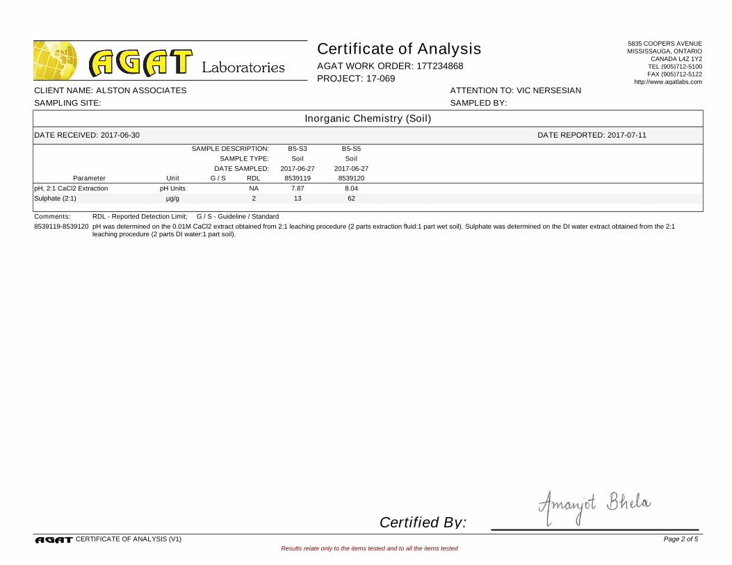
B5-S5B5-S3SAMPLE DESCRIPTION:
SoilSoilSAMPLE TYPE:
2017-06-272017-06-27DATE SAMPLED:
8539119 8539120G / S RDLUnitParameter
7.87 8.04pH, 2:1 CaCl2 Extraction NApH Units
13 62Sulphate (2:1) 2µg/g
Comments: RDL - Reported Detection Limit; G / S - Guideline / Standard
8539119-8539120 pH was determined on the 0.01M CaCl2 extract obtained from 2:1 leaching procedure (2 parts extraction fluid:1 part wet soil). Sulphate was determined on the DI water extract obtained from the 2:1 leaching procedure (2 parts DI water:1 part soil).
Results relate only to the items tested and to all the items tested
DATE RECEIVED: 2017-06-30
Certificate of Analysis
ATTENTION TO: VIC NERSESIANCLIENT NAME: ALSTON ASSOCIATES
AGAT WORK ORDER: 17T234868
DATE REPORTED: 2017-07-11
PROJECT: 17-069
Inorganic Chemistry (Soil)
SAMPLED BY:SAMPLING SITE:
5835 COOPERS AVENUEMISSISSAUGA, ONTARIO
CANADA L4Z 1Y2TEL (905)712-5100FAX (905)712-5122
http://www.agatlabs.com
CERTIFICATE OF ANALYSIS (V1)
Certified By:Page 2 of 5
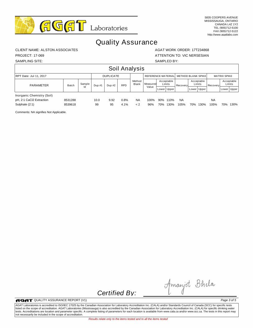
Inorganic Chemistry (Soil)
pH, 2:1 CaCl2 Extraction 8531288 10.0 9.92 0.8% NA 100% 90% 110% NA NA
Sulphate (2:1) 8539618 99 95 4.1% < 2 96% 70% 130% 105% 70% 130% 105% 70% 130%
Comments: NA signifies Not Applicable.
Certified By:
Results relate only to the items tested and to all the items tested
SAMPLING SITE: SAMPLED BY:
AGAT WORK ORDER: 17T234868
Dup #1 RPDMeasured
ValueRecovery Recovery
Quality Assurance
ATTENTION TO: VIC NERSESIAN
CLIENT NAME: ALSTON ASSOCIATES
PROJECT: 17-069
Soil Analysis
UpperLower
AcceptableLimits
BatchPARAMETERSample
IdDup #2
UpperLower
AcceptableLimits
UpperLower
AcceptableLimits
MATRIX SPIKEMETHOD BLANK SPIKEDUPLICATERPT Date: Jul 11, 2017 REFERENCE MATERIAL
MethodBlank
5835 COOPERS AVENUEMISSISSAUGA, ONTARIO
CANADA L4Z 1Y2TEL (905)712-5100FAX (905)712-5122
http://www.agatlabs.com
QUALITY ASSURANCE REPORT (V1) Page 3 of 5
AGAT Laboratories is accredited to ISO/IEC 17025 by the Canadian Association for Laboratory Accreditation Inc. (CALA) and/or Standards Council of Canada (SCC) for specific tests listed on the scope of accreditation. AGAT Laboratories (Mississauga) is also accredited by the Canadian Association for Laboratory Accreditation Inc. (CALA) for specific drinking water tests. Accreditations are location and parameter specific. A complete listing of parameters for each location is available from www.cala.ca and/or www.scc.ca. The tests in this report may not necessarily be included in the scope of accreditation.

Soil Analysis
pH, 2:1 CaCl2 Extraction INOR-93-6031 MSA part 3 & SM 4500-H+ B pH METER
Sulphate (2:1) INOR-93-6004 McKeague 4.12 & SM 4110 B ION CHROMATOGRAPH
Results relate only to the items tested and to all the items tested
SAMPLING SITE: SAMPLED BY:
AGAT WORK ORDER: 17T234868
Method Summary
ATTENTION TO: VIC NERSESIAN
CLIENT NAME: ALSTON ASSOCIATES
PROJECT: 17-069
AGAT S.O.P ANALYTICAL TECHNIQUELITERATURE REFERENCEPARAMETER
5835 COOPERS AVENUEMISSISSAUGA, ONTARIO
CANADA L4Z 1Y2TEL (905)712-5100FAX (905)712-5122
http://www.agatlabs.com
METHOD SUMMARY (V1) Page 4 of 5
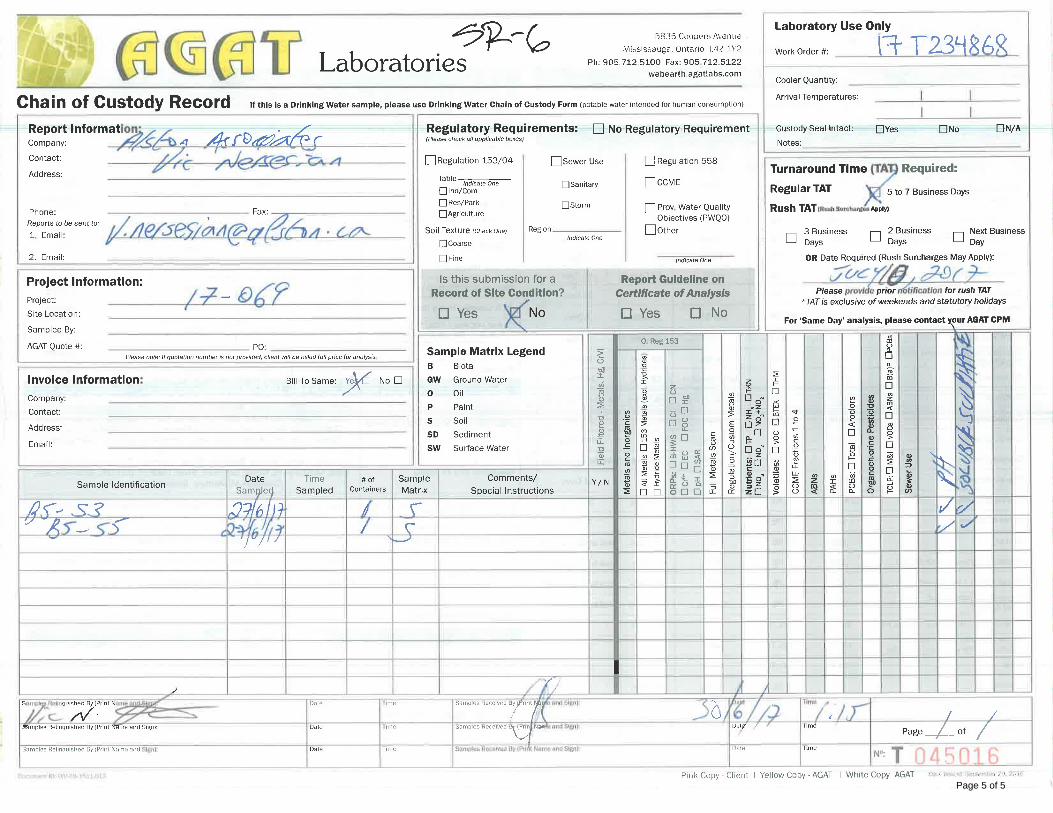
Page 5 of 5

alston associates Reference 17-069
A division of Terrapex Environmental Ltd. April 2019
GEOTECHNICAL INVESTIGATION REPORT
1950 AND 1952 FAIRPORT ROAD, PICKERING, ONTARIO
10046043 CANADA INC.
APPENDIX G SLOPE STABILITY ANALYSIS CROSS SECTIONS
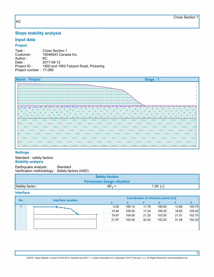
KCCross Section 1
1[GEO5 - Slope Stability | version 5.2016.56.0 | hardware key 8221 / 1 | Alston Associates Inc | Copyright © 2017 Fine spol. s r.o. All Rights Reserved | www.finesoftware.eu]
Slope stability analysisInput dataProjectTask :Customer :Author :Date :Project ID :Project number :
Cross Section 110046043 Canada Inc.KC2017-09-121950 and 1952 Fairport Road, Pickering17-069
Name : Project Stage : 1
SettingsStandard - safety factorsStability analysisEarthquake analysis :Verification methodology :
StandardSafety factors (ASD)
Safety factorsPermanent design situation
Safety factor : SFs = 1.50 [–]
Interface
No. Interface locationCoordinates of interface points [m]
x z x z x z1 0.00
15.4619.9721.97
106.10105.50104.00102.50
11.7817.2421.2022.43
106.00105.25103.00102.20
13.6618.6521.5131.58
105.75105.00102.75102.20
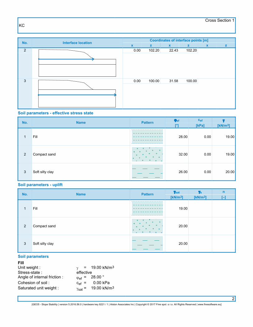
KCCross Section 1
2[GEO5 - Slope Stability | version 5.2016.56.0 | hardware key 8221 / 1 | Alston Associates Inc | Copyright © 2017 Fine spol. s r.o. All Rights Reserved | www.finesoftware.eu]
No. Interface locationCoordinates of interface points [m]
x z x z x z2
3
0.00
0.00
102.20
100.00
22.43
31.58
102.20
100.00
Soil parameters - effective stress state
No. Name Patternjef[°]
cef[kPa]
g
[kN/m3]
1
2
3
Fill
Compact sand
Soft silty clay
28.00
32.00
26.00
0.00
0.00
0.00
19.00
19.00
20.00
Soil parameters - uplift
No. Name Patterngsat
[kN/m3]gs
[kN/m3]n[–]
1
2
3
Fill
Compact sand
Soft silty clay
19.00
20.00
20.00
Soil parametersFillUnit weight :Stress-state :Angle of internal friction :Cohesion of soil :Saturated unit weight :
geffectivejefcefgsat
=
===
19.00
28.000.00
19.00
kN/m3
°kPakN/m3
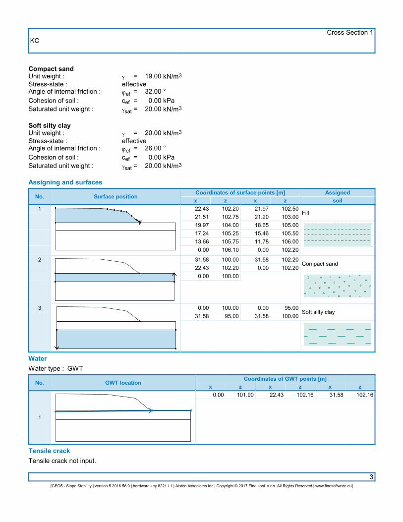
KCCross Section 1
3[GEO5 - Slope Stability | version 5.2016.56.0 | hardware key 8221 / 1 | Alston Associates Inc | Copyright © 2017 Fine spol. s r.o. All Rights Reserved | www.finesoftware.eu]
Compact sandUnit weight :Stress-state :Angle of internal friction :Cohesion of soil :Saturated unit weight :
geffectivejefcefgsat
=
===
19.00
32.000.00
20.00
kN/m3
°kPakN/m3
Soft silty clayUnit weight :Stress-state :Angle of internal friction :Cohesion of soil :Saturated unit weight :
geffectivejefcefgsat
=
===
20.00
26.000.00
20.00
kN/m3
°kPakN/m3
Assigning and surfaces
No. Surface positionCoordinates of surface points [m]x z x z
Assignedsoil
1
2
3
22.4321.5119.9717.2413.660.00
31.5822.430.00
0.0031.58
102.20102.75104.00105.25105.75106.10
100.00102.20100.00
100.0095.00
21.9721.2018.6515.4611.780.00
31.580.00
0.0031.58
102.50103.00105.00105.50106.00102.20
102.20102.20
95.00100.00
Fill
Compact sand
Soft silty clay
WaterWater type : GWT
No. GWT locationCoordinates of GWT points [m]
x z x z x z
1
0.00 101.90 22.43 102.16 31.58 102.16
Tensile crackTensile crack not input.
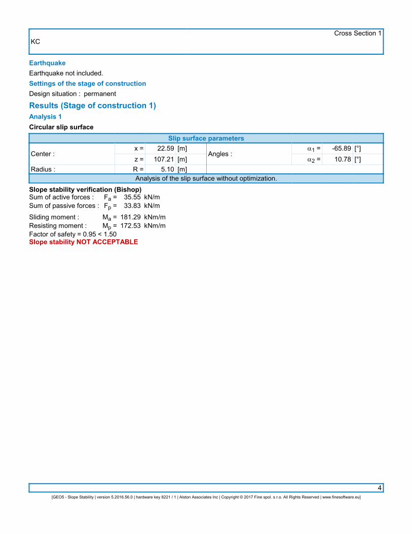
KCCross Section 1
4[GEO5 - Slope Stability | version 5.2016.56.0 | hardware key 8221 / 1 | Alston Associates Inc | Copyright © 2017 Fine spol. s r.o. All Rights Reserved | www.finesoftware.eu]
EarthquakeEarthquake not included.Settings of the stage of constructionDesign situation : permanent
Results (Stage of construction 1)Analysis 1Circular slip surface
Slip surface parameters
Center :
Radius :
x =z =R =
22.59107.21
5.10
[m][m][m]
Angles :a1 =a2 =
-65.8910.78
[°][°]
Analysis of the slip surface without optimization.Slope stability verification (Bishop)Sum of active forces :Sum of passive forces :
Sliding moment :Resisting moment :
Fa =Fp =
Ma =Mp =
35.5533.83
181.29172.53
kN/mkN/m
kNm/mkNm/m
Factor of safety = 0.95 < 1.50Slope stability NOT ACCEPTABLE
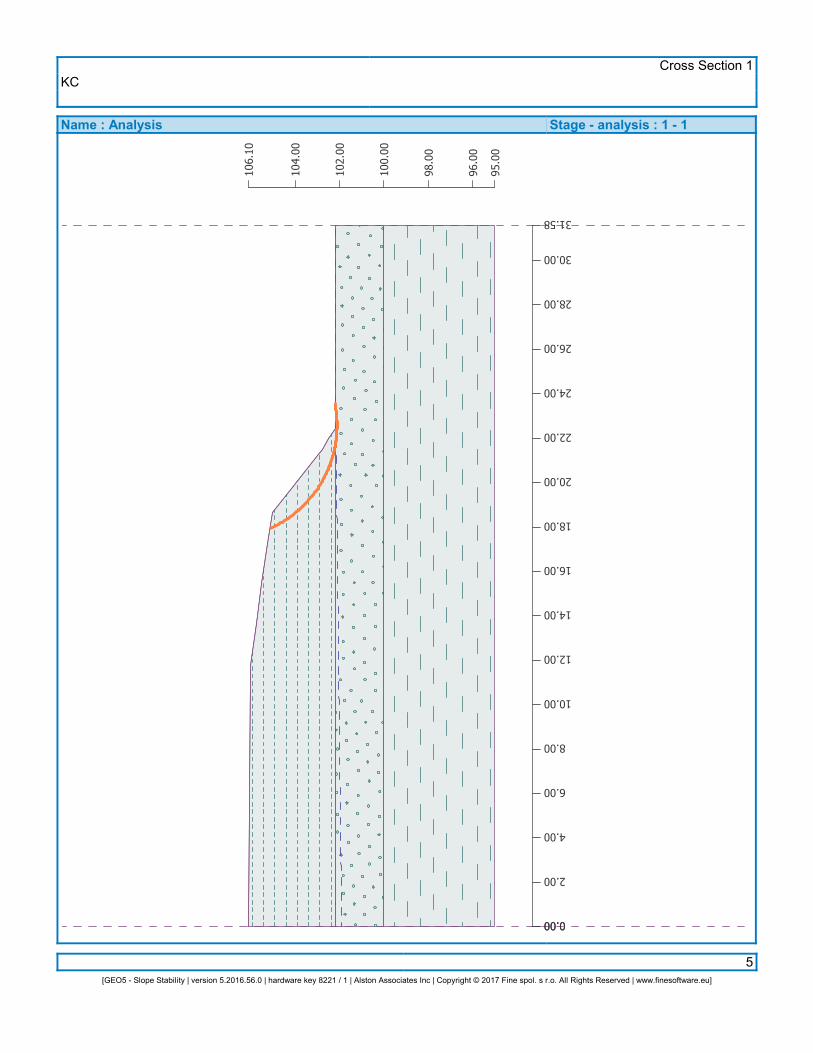
KCCross Section 1
5[GEO5 - Slope Stability | version 5.2016.56.0 | hardware key 8221 / 1 | Alston Associates Inc | Copyright © 2017 Fine spol. s r.o. All Rights Reserved | www.finesoftware.eu]
Name : Analysis Stage - analysis : 1 - 10.00 0.00
2.00
4.00
6.00
8.00
10.00
12.00
14.00
16.00
18.00
20.00
22.00
24.00
26.00
28.00
30.00
31.58
95.0
0
96.0
0
98.0
0
100.
00
102.
00
104.
00
106.
10

KCCross Section 1
6[GEO5 - Slope Stability | version 5.2016.56.0 | hardware key 8221 / 1 | Alston Associates Inc | Copyright © 2017 Fine spol. s r.o. All Rights Reserved | www.finesoftware.eu]
Analysis 2Circular slip surface
Slip surface parameters
Center :
Radius :
x =z =R =
24.82122.9620.93
[m][m][m]
Angles :a1 =a2 =
-35.287.31
[°][°]
Analysis of the slip surface without optimization.Slope stability verification (Bishop)Sum of active forces :Sum of passive forces :
Sliding moment :Resisting moment :
Fa =Fp =
Ma =Mp =
72.71113.04
1521.762365.92
kN/mkN/m
kNm/mkNm/m
Factor of safety = 1.55 > 1.50Slope stability ACCEPTABLE
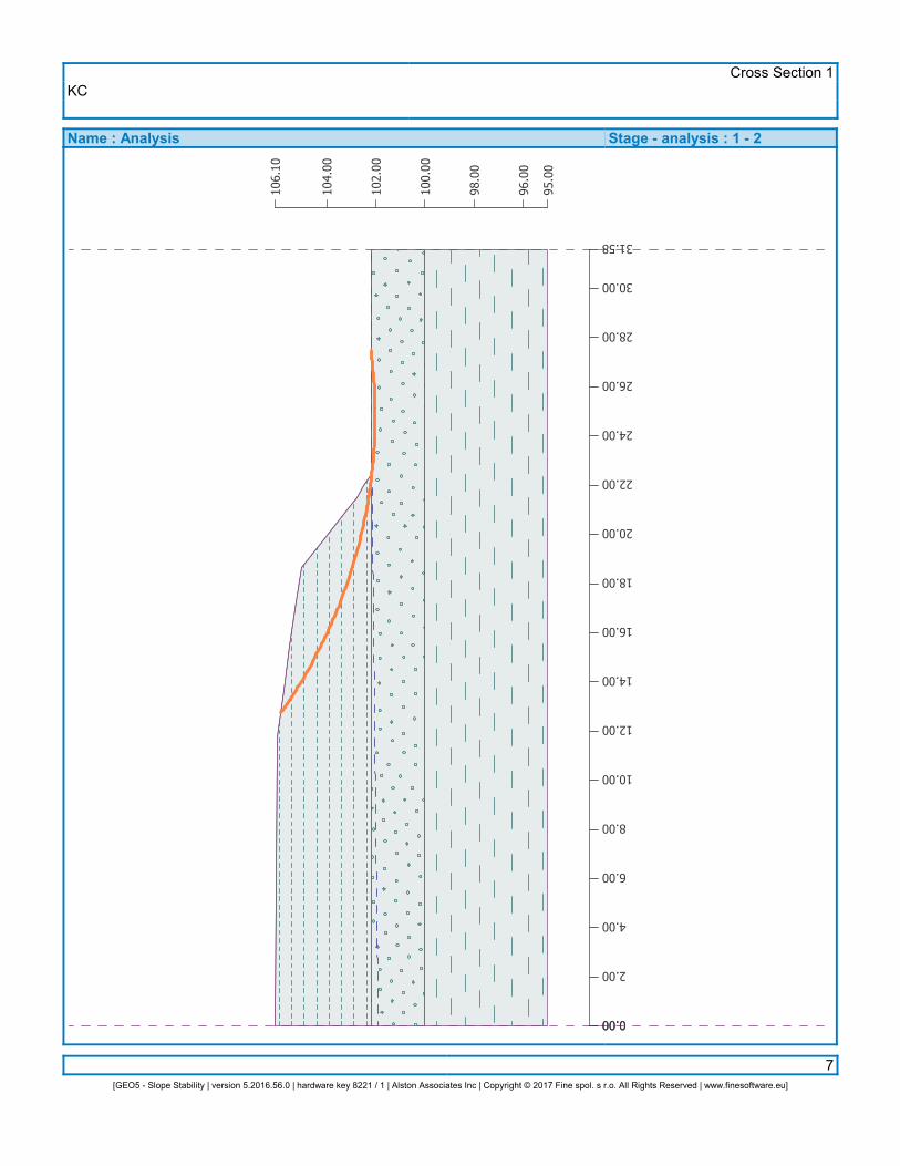
KCCross Section 1
7[GEO5 - Slope Stability | version 5.2016.56.0 | hardware key 8221 / 1 | Alston Associates Inc | Copyright © 2017 Fine spol. s r.o. All Rights Reserved | www.finesoftware.eu]
Name : Analysis Stage - analysis : 1 - 20.00 0.00
2.00
4.00
6.00
8.00
10.00
12.00
14.00
16.00
18.00
20.00
22.00
24.00
26.00
28.00
30.00
31.58
95.0
0
96.0
0
98.0
0
100.
00
102.
00
104.
00
106.
10
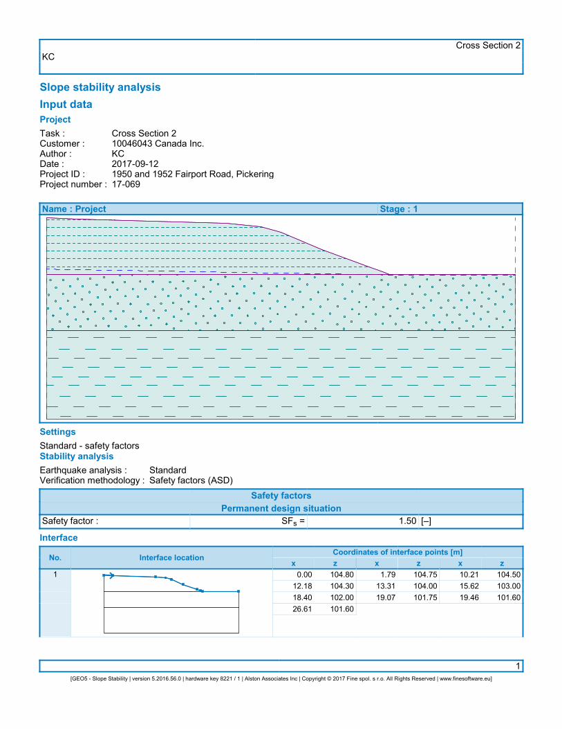
KCCross Section 2
1[GEO5 - Slope Stability | version 5.2016.56.0 | hardware key 8221 / 1 | Alston Associates Inc | Copyright © 2017 Fine spol. s r.o. All Rights Reserved | www.finesoftware.eu]
Slope stability analysisInput dataProjectTask :Customer :Author :Date :Project ID :Project number :
Cross Section 210046043 Canada Inc.KC2017-09-121950 and 1952 Fairport Road, Pickering17-069
Name : Project Stage : 1
SettingsStandard - safety factorsStability analysisEarthquake analysis :Verification methodology :
StandardSafety factors (ASD)
Safety factorsPermanent design situation
Safety factor : SFs = 1.50 [–]
Interface
No. Interface locationCoordinates of interface points [m]
x z x z x z1 0.00
12.1818.4026.61
104.80104.30102.00101.60
1.7913.3119.07
104.75104.00101.75
10.2115.6219.46
104.50103.00101.60
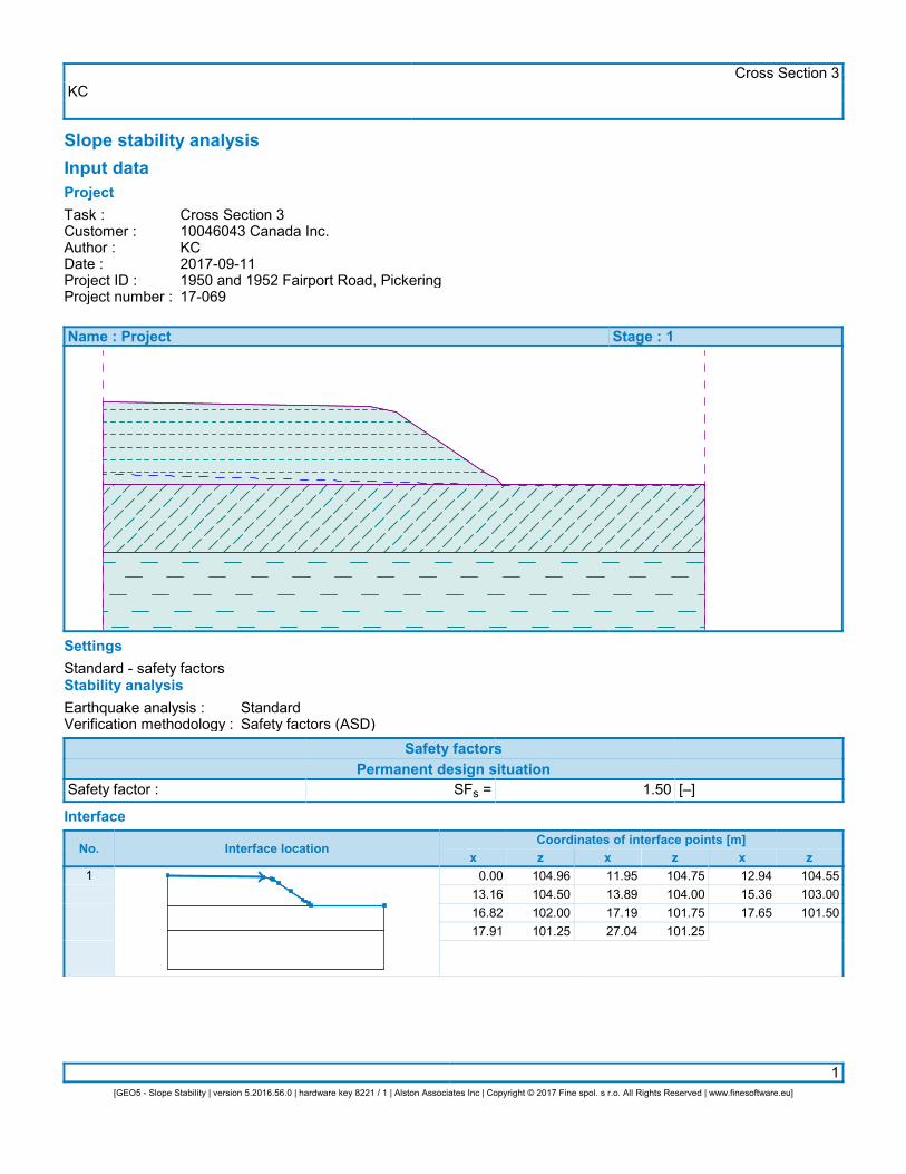
KCCross Section 3
1[GEO5 - Slope Stability | version 5.2016.56.0 | hardware key 8221 / 1 | Alston Associates Inc | Copyright © 2017 Fine spol. s r.o. All Rights Reserved | www.finesoftware.eu]
Slope stability analysisInput dataProjectTask :Customer :Author :Date :Project ID :Project number :
Cross Section 310046043 Canada Inc.KC2017-09-111950 and 1952 Fairport Road, Pickering17-069
Name : Project Stage : 1
SettingsStandard - safety factorsStability analysisEarthquake analysis :Verification methodology :
StandardSafety factors (ASD)
Safety factorsPermanent design situation
Safety factor : SFs = 1.50 [–]
Interface
No. Interface locationCoordinates of interface points [m]
x z x z x z1 0.00
13.1616.8217.91
104.96104.50102.00101.25
11.9513.8917.1927.04
104.75104.00101.75101.25
12.9415.3617.65
104.55103.00101.50
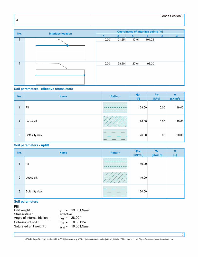
KCCross Section 3
2[GEO5 - Slope Stability | version 5.2016.56.0 | hardware key 8221 / 1 | Alston Associates Inc | Copyright © 2017 Fine spol. s r.o. All Rights Reserved | www.finesoftware.eu]
No. Interface locationCoordinates of interface points [m]
x z x z x z2
3
0.00
0.00
101.25
98.20
17.91
27.04
101.25
98.20
Soil parameters - effective stress state
No. Name Patternjef[°]
cef[kPa]
g
[kN/m3]
1
2
3
Fill
Loose silt
Soft silty clay
28.00
28.00
26.00
0.00
0.00
0.00
19.00
19.00
20.00
Soil parameters - uplift
No. Name Patterngsat
[kN/m3]gs
[kN/m3]n[–]
1
2
3
Fill
Loose silt
Soft silty clay
19.00
19.00
20.00
Soil parametersFillUnit weight :Stress-state :Angle of internal friction :Cohesion of soil :Saturated unit weight :
geffectivejefcefgsat
=
===
19.00
28.000.00
19.00
kN/m3
°kPakN/m3
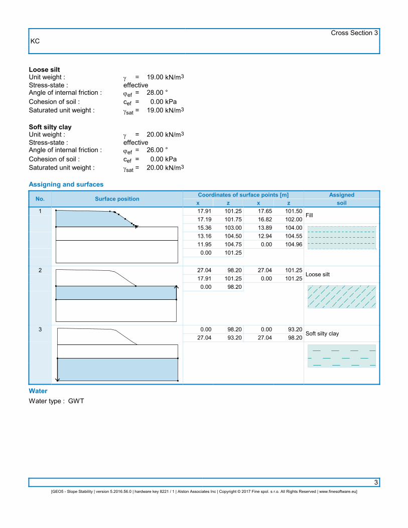
KCCross Section 3
3[GEO5 - Slope Stability | version 5.2016.56.0 | hardware key 8221 / 1 | Alston Associates Inc | Copyright © 2017 Fine spol. s r.o. All Rights Reserved | www.finesoftware.eu]
Loose siltUnit weight :Stress-state :Angle of internal friction :Cohesion of soil :Saturated unit weight :
geffectivejefcefgsat
=
===
19.00
28.000.00
19.00
kN/m3
°kPakN/m3
Soft silty clayUnit weight :Stress-state :Angle of internal friction :Cohesion of soil :Saturated unit weight :
geffectivejefcefgsat
=
===
20.00
26.000.00
20.00
kN/m3
°kPakN/m3
Assigning and surfaces
No. Surface positionCoordinates of surface points [m]x z x z
Assignedsoil
1
2
3
17.9117.1915.3613.1611.950.00
27.0417.910.00
0.0027.04
101.25101.75103.00104.50104.75101.25
98.20101.2598.20
98.2093.20
17.6516.8213.8912.940.00
27.040.00
0.0027.04
101.50102.00104.00104.55104.96
101.25101.25
93.2098.20
Fill
Loose silt
Soft silty clay
WaterWater type : GWT
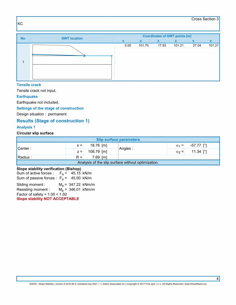
KCCross Section 3
4[GEO5 - Slope Stability | version 5.2016.56.0 | hardware key 8221 / 1 | Alston Associates Inc | Copyright © 2017 Fine spol. s r.o. All Rights Reserved | www.finesoftware.eu]
No. GWT locationCoordinates of GWT points [m]
x z x z x z
1
0.00 101.70 17.93 101.21 27.04 101.21
Tensile crackTensile crack not input.EarthquakeEarthquake not included.Settings of the stage of constructionDesign situation : permanent
Results (Stage of construction 1)Analysis 1Circular slip surface
Slip surface parameters
Center :
Radius :
x =z =R =
18.76108.79
7.69
[m][m][m]
Angles :a1 =a2 =
-57.7711.34
[°][°]
Analysis of the slip surface without optimization.Slope stability verification (Bishop)Sum of active forces :Sum of passive forces :
Sliding moment :Resisting moment :
Fa =Fp =
Ma =Mp =
45.1545.00
347.22346.01
kN/mkN/m
kNm/mkNm/m
Factor of safety = 1.00 < 1.50Slope stability NOT ACCEPTABLE

KCCross Section 3
5[GEO5 - Slope Stability | version 5.2016.56.0 | hardware key 8221 / 1 | Alston Associates Inc | Copyright © 2017 Fine spol. s r.o. All Rights Reserved | www.finesoftware.eu]
Name : Analysis Stage - analysis : 1 - 10.00 0.00
2.00
4.00
6.00
8.00
10.00
12.00
14.00
16.00
18.00
20.00
22.00
24.00
26.00
27.04
93.2
0
94.0
0
96.0
0
98.0
0
100.
00
102.
00
104.
00
104.
96
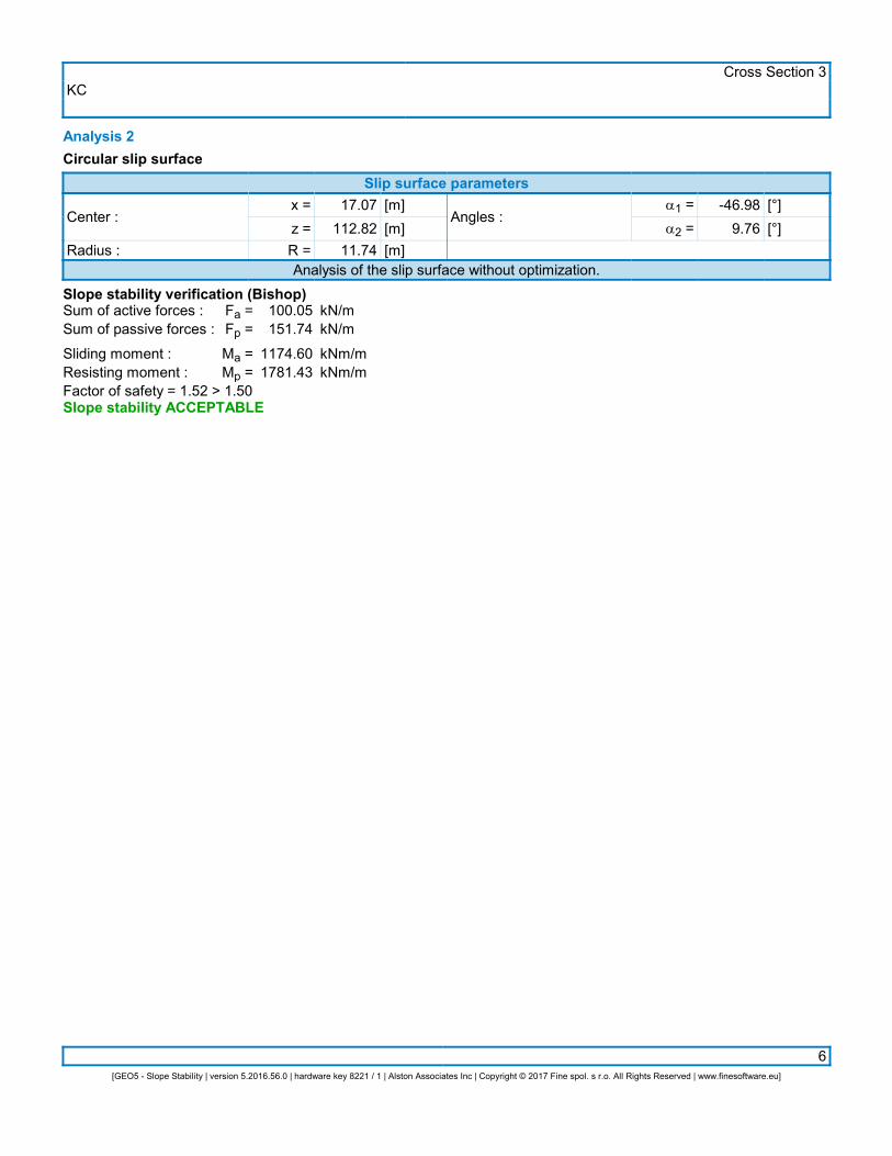
KCCross Section 3
6[GEO5 - Slope Stability | version 5.2016.56.0 | hardware key 8221 / 1 | Alston Associates Inc | Copyright © 2017 Fine spol. s r.o. All Rights Reserved | www.finesoftware.eu]
Analysis 2Circular slip surface
Slip surface parameters
Center :
Radius :
x =z =R =
17.07112.8211.74
[m][m][m]
Angles :a1 =a2 =
-46.989.76
[°][°]
Analysis of the slip surface without optimization.Slope stability verification (Bishop)Sum of active forces :Sum of passive forces :
Sliding moment :Resisting moment :
Fa =Fp =
Ma =Mp =
100.05151.74
1174.601781.43
kN/mkN/m
kNm/mkNm/m
Factor of safety = 1.52 > 1.50Slope stability ACCEPTABLE
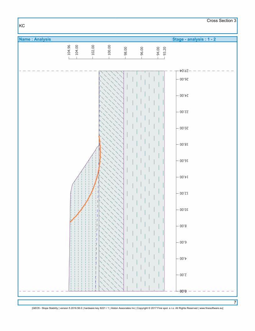
KCCross Section 3
7[GEO5 - Slope Stability | version 5.2016.56.0 | hardware key 8221 / 1 | Alston Associates Inc | Copyright © 2017 Fine spol. s r.o. All Rights Reserved | www.finesoftware.eu]
Name : Analysis Stage - analysis : 1 - 20.00 0.00
2.00
4.00
6.00
8.00
10.00
12.00
14.00
16.00
18.00
20.00
22.00
24.00
26.00
27.04
93.2
0
94.0
0
96.0
0
98.0
0
100.
00
102.
00
104.
00
104.
96

KCCross Section 2
2[GEO5 - Slope Stability | version 5.2016.56.0 | hardware key 8221 / 1 | Alston Associates Inc | Copyright © 2017 Fine spol. s r.o. All Rights Reserved | www.finesoftware.eu]
No. Interface locationCoordinates of interface points [m]
x z x z x z2
3
0.00
0.00
101.60
98.40
19.46
26.61
101.60
98.40
Soil parameters - effective stress state
No. Name Patternjef[°]
cef[kPa]
g
[kN/m3]
1
2
3
Fill
Compact sand
Soft silty clay
28.00
32.00
26.00
0.00
0.00
0.00
19.00
19.00
20.00
Soil parameters - uplift
No. Name Patterngsat
[kN/m3]gs
[kN/m3]n[–]
1
2
3
Fill
Compact sand
Soft silty clay
19.00
19.00
20.00
Soil parametersFillUnit weight :Stress-state :Angle of internal friction :Cohesion of soil :Saturated unit weight :
geffectivejefcefgsat
=
===
19.00
28.000.00
19.00
kN/m3
°kPakN/m3
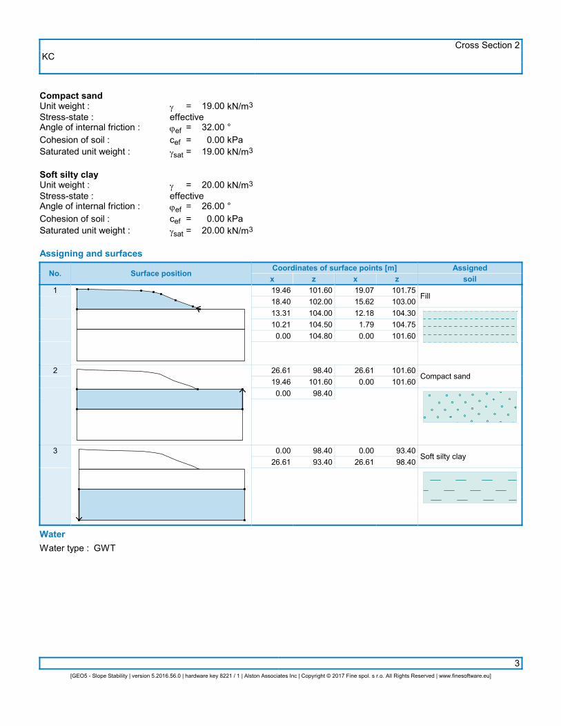
KCCross Section 2
3[GEO5 - Slope Stability | version 5.2016.56.0 | hardware key 8221 / 1 | Alston Associates Inc | Copyright © 2017 Fine spol. s r.o. All Rights Reserved | www.finesoftware.eu]
Compact sandUnit weight :Stress-state :Angle of internal friction :Cohesion of soil :Saturated unit weight :
geffectivejefcefgsat
=
===
19.00
32.000.00
19.00
kN/m3
°kPakN/m3
Soft silty clayUnit weight :Stress-state :Angle of internal friction :Cohesion of soil :Saturated unit weight :
geffectivejefcefgsat
=
===
20.00
26.000.00
20.00
kN/m3
°kPakN/m3
Assigning and surfaces
No. Surface positionCoordinates of surface points [m]x z x z
Assignedsoil
1
2
3
19.4618.4013.3110.210.00
26.6119.460.00
0.0026.61
101.60102.00104.00104.50104.80
98.40101.6098.40
98.4093.40
19.0715.6212.181.790.00
26.610.00
0.0026.61
101.75103.00104.30104.75101.60
101.60101.60
93.4098.40
Fill
Compact sand
Soft silty clay
WaterWater type : GWT
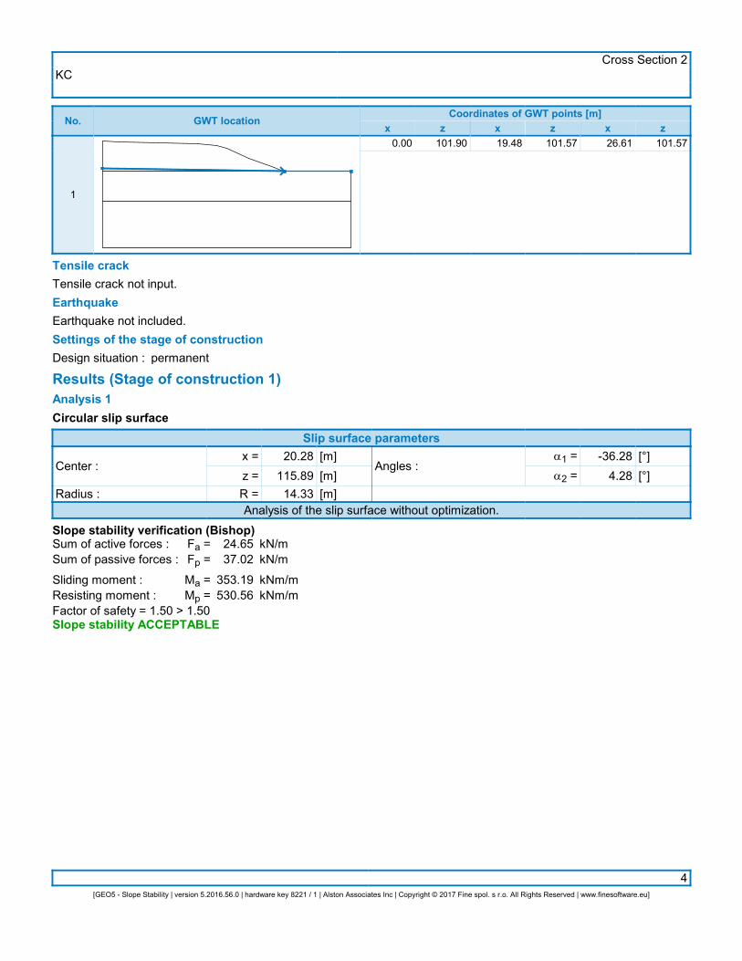
KCCross Section 2
4[GEO5 - Slope Stability | version 5.2016.56.0 | hardware key 8221 / 1 | Alston Associates Inc | Copyright © 2017 Fine spol. s r.o. All Rights Reserved | www.finesoftware.eu]
No. GWT locationCoordinates of GWT points [m]
x z x z x z
1
0.00 101.90 19.48 101.57 26.61 101.57
Tensile crackTensile crack not input.EarthquakeEarthquake not included.Settings of the stage of constructionDesign situation : permanent
Results (Stage of construction 1)Analysis 1Circular slip surface
Slip surface parameters
Center :
Radius :
x =z =R =
20.28115.8914.33
[m][m][m]
Angles :a1 =a2 =
-36.284.28
[°][°]
Analysis of the slip surface without optimization.Slope stability verification (Bishop)Sum of active forces :Sum of passive forces :
Sliding moment :Resisting moment :
Fa =Fp =
Ma =Mp =
24.6537.02
353.19530.56
kN/mkN/m
kNm/mkNm/m
Factor of safety = 1.50 > 1.50Slope stability ACCEPTABLE
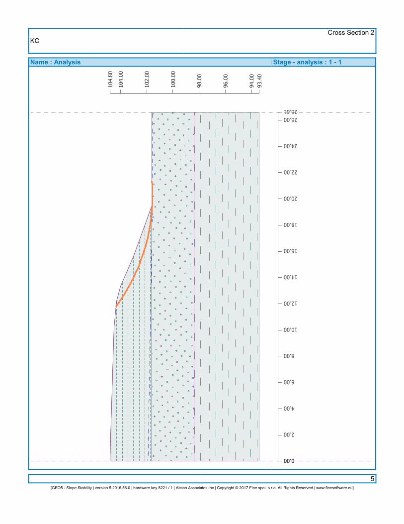
KCCross Section 2
5[GEO5 - Slope Stability | version 5.2016.56.0 | hardware key 8221 / 1 | Alston Associates Inc | Copyright © 2017 Fine spol. s r.o. All Rights Reserved | www.finesoftware.eu]
Name : Analysis Stage - analysis : 1 - 10.00 0.00
2.00
4.00
6.00
8.00
10.00
12.00
14.00
16.00
18.00
20.00
22.00
24.00
26.0026.61
93.4
094
.00
96.0
0
98.0
0
100.
00
102.
00
104.
00
104.
80


![Modern and relict features in clayey cryogenic soils ... · [ MODERN AND RELICT FEATURES IN CLAYEY CRYOGENIC SOILS: MORPHOLOGICAL AND MICROMORPHOLOGICAL IDENTIFICATION ] The purpose](https://img.pdfslide.net/doc/110x75/5e364e0f0498275a8e16289c/modern-and-relict-features-in-clayey-cryogenic-soils-modern-and-relict-features.jpg)