Embed Size (px)
Citation preview

2712 Satsuma Drive, Suite 400 ⧫Dallas, Texas 75229⧫ 972.488.3500 (P) ⧫e-mail: [email protected]
GEOTECHNICAL INVESTIGATION
Proposed DUTCH BROS. COFFEE -TX 0507
6301 N Beach St
Fort Worth, Texas
PROJECT NO. 21-DG6556
Prepared for:
DUTCH BROS. COFFEE
Grants Pass, OR
Prepared by:
GEOSCIENCE ENGINEERS, LLC.
Dallas, Texas
August 2021


Proposed DUTCH BROS. COFFEE
6301 N Beach St
Fort Worth, Texas
GEOSCIENCE ENGINEERING, LLC
CONTENTS Pages
INTRODUCTION ............................................................................................................................................ 1
Project Description .................................................................................................................................. 1
Site Description ........................................................................................................................................ 1
Purposes and Scope of Work ................................................................................................................. 1
Report Format .......................................................................................................................................... 1
FIELD INVESTIGATION .................................................................................................................................. 2
LABORATORY TESTING ................................................................................................................................ 2
Review ...................................................................................................................................................... 2
GENERAL SUBSURFACE CONDITIONS ........................................................................................................ 3
Stratigraphy .............................................................................................................................................. 3
Subsurface Water Conditions ................................................................................................................ 3
ANALYSIS AND RECOMMENDATIONS ....................................................................................................... 3
Construction Consultation and Monitoring.......................................................................................... 3
Soil Movement ......................................................................................................................................... 4
FOUNDATION TYPE ...................................................................................................................................... 6
Shallow Footings ...................................................................................................................................... 6
Continuous Footings ............................................................................................................................... 7
Floor Slab .................................................................................................................................................. 7
Building Pad Preparation ....................................................................................................................... 7
Select Fill ................................................................................................................................................... 8
Flex Base ................................................................................................................................................... 8
PAVEMENT RECOMMENDATION................................................................................................................ 8
SITE GRADING and DRAINAGE ................................................................................................................ 12
CLOSURE .................................................................................................................................................... 13
ILLUSTRATIONS Pages
LOCATION PLAN ............................................................................................................................... A
BORING LOGS ................................................................................................................................. 1-4
FREE SWELL TEST ................................................................................................................................ 5
Proposed DUTCH BROS. COFFEE
6301 N Beach St
Fort Worth, Texas
GEOSCIENCE ENGINEERING, LLC -1-
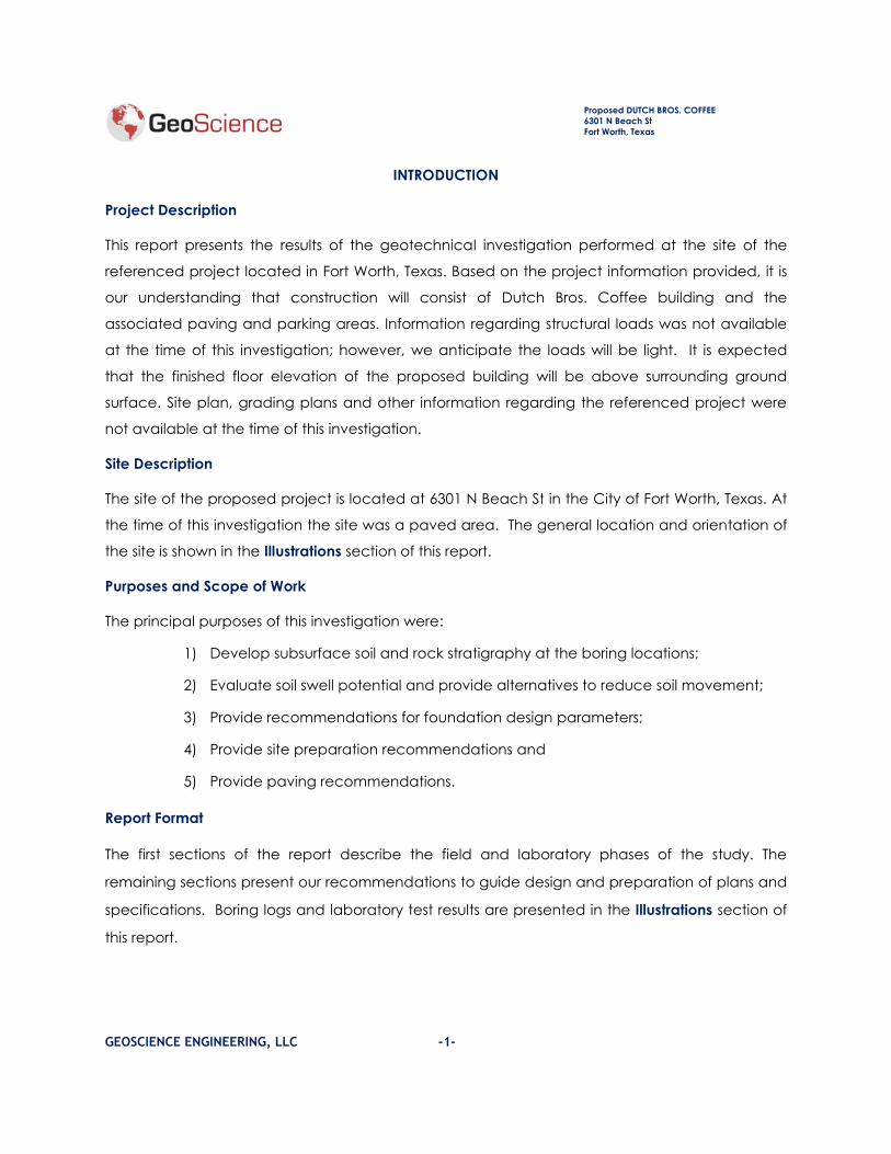
INTRODUCTION
Project Description
This report presents the results of the geotechnical investigation performed at the site of the
referenced project located in Fort Worth, Texas. Based on the project information provided, it is
our understanding that construction will consist of Dutch Bros. Coffee building and the
associated paving and parking areas. Information regarding structural loads was not available
at the time of this investigation; however, we anticipate the loads will be light. It is expected
that the finished floor elevation of the proposed building will be above surrounding ground
surface. Site plan, grading plans and other information regarding the referenced project were
not available at the time of this investigation.
Site Description
The site of the proposed project is located at 6301 N Beach St in the City of Fort Worth, Texas. At
the time of this investigation the site was a paved area. The general location and orientation of
the site is shown in the Illustrations section of this report.
Purposes and Scope of Work
The principal purposes of this investigation were:
1) Develop subsurface soil and rock stratigraphy at the boring locations;
2) Evaluate soil swell potential and provide alternatives to reduce soil movement;
3) Provide recommendations for foundation design parameters;
4) Provide site preparation recommendations and
5) Provide paving recommendations.
Report Format
The first sections of the report describe the field and laboratory phases of the study. The
remaining sections present our recommendations to guide design and preparation of plans and
specifications. Boring logs and laboratory test results are presented in the Illustrations section of
this report.
Proposed DUTCH BROS. COFFEE
6301 N Beach St
Fort Worth, Texas
GEOSCIENCE ENGINEERING, LLC -2-
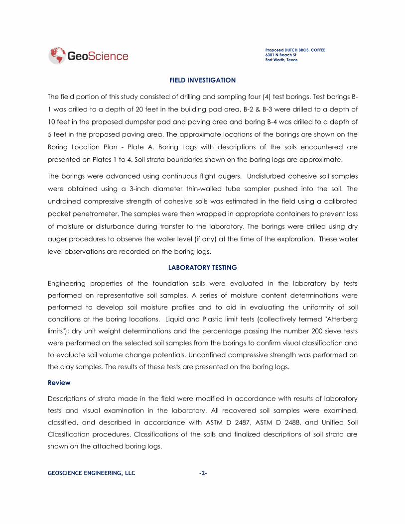
FIELD INVESTIGATION
The field portion of this study consisted of drilling and sampling four (4) test borings. Test borings B-
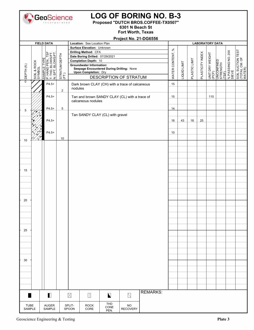
1 was drilled to a depth of 20 feet in the building pad area, B-2 & B-3 were drilled to a depth of
10 feet in the proposed dumpster pad and paving area and boring B-4 was drilled to a depth of
5 feet in the proposed paving area. The approximate locations of the borings are shown on the
Boring Location Plan - Plate A. Boring Logs with descriptions of the soils encountered are
presented on Plates 1 to 4. Soil strata boundaries shown on the boring logs are approximate.
The borings were advanced using continuous flight augers. Undisturbed cohesive soil samples
were obtained using a 3-inch diameter thin-walled tube sampler pushed into the soil. The
undrained compressive strength of cohesive soils was estimated in the field using a calibrated
pocket penetrometer. The samples were then wrapped in appropriate containers to prevent loss
of moisture or disturbance during transfer to the laboratory. The borings were drilled using dry
auger procedures to observe the water level (if any) at the time of the exploration. These water
level observations are recorded on the boring logs.
LABORATORY TESTING
Engineering properties of the foundation soils were evaluated in the laboratory by tests
performed on representative soil samples. A series of moisture content determinations were
performed to develop soil moisture profiles and to aid in evaluating the uniformity of soil
conditions at the boring locations. Liquid and Plastic limit tests (collectively termed "Atterberg
limits"); dry unit weight determinations and the percentage passing the number 200 sieve tests
were performed on the selected soil samples from the borings to confirm visual classification and
to evaluate soil volume change potentials. Unconfined compressive strength was performed on
the clay samples. The results of these tests are presented on the boring logs.
Review
Descriptions of strata made in the field were modified in accordance with results of laboratory
tests and visual examination in the laboratory. All recovered soil samples were examined,
classified, and described in accordance with ASTM D 2487, ASTM D 2488, and Unified Soil
Classification procedures. Classifications of the soils and finalized descriptions of soil strata are
shown on the attached boring logs.

Proposed DUTCH BROS. COFFEE
6301 N Beach St
Fort Worth, Texas
GEOSCIENCE ENGINEERING, LLC -3-
GENERAL SUBSURFACE CONDITIONS
Stratigraphy
Based on our interpretations, the overall subsurface stratigraphy at the locations of the test
borings drilled for this study consists of dark brown clay with a trace of calcareous nodules from
existing ground surface elevation and remained visible to the completion depth of test boring B-
4 and to a depth of 2 to 6 feet in the test borings B-1, B-2, and B-3. Below clay soils, tan and
brown sandy clay soils with a trace of calcareous nodules were encountered and remained
visible to a depth of 5 and 13 feet at the location of test boring B-1, B-2, and B-3. Tan sandy clay
with gravel was encountered at depth of 5 to 13 feet and remained visible to the completion
depth of the test borings drilled. It should be noted that the upper 5 inches of the materials
encountered at the location of test boring B-2 consisted of concrete pavement.
Detailed descriptions of the subsurface stratigraphy encountered at the locations of the test
borings drilled for this study are included in the Illustrations section of this report.
Subsurface Water Conditions
The borings were advanced using auger drilling methods in order to observe groundwater
seepage levels. At the time of this investigation, NO groundwater seepage was encountered at
any of the test borings drilled for this study. However, it should be noted that future construction
activities may alter the surface and subsurface drainage characteristics of this site. As such, we
suggest re-verifying the depth to groundwater just prior to and during construction. Based on
short-term observations, it is not possible to accurately predict the magnitude of subsurface
water fluctuations that might occur. In addition, it is not uncommon to detect water seepage
occurring in soils fractures, particularly after periods of heavy rainfall.
ANALYSIS AND RECOMMENDATIONS
Construction Consultation and Monitoring
We recommend that Geoscience be given the opportunity to review the final design drawings
and specifications in order to evaluate if recommendations in this report have been properly
interpreted. Wide variations in soil conditions are known to exist between the borings, particularly
at this site. Further unanticipated variations in subsurface conditions may become evident
during construction. During excavation and foundation phases of the work, we recommend

Proposed DUTCH BROS. COFFEE
6301 N Beach St
Fort Worth, Texas
GEOSCIENCE ENGINEERING, LLC -4-
that a reputable geotechnical engineering firm be retained to provide construction surveillance
services in order to 1) observe compliance with the geotechnical design concepts,
specifications, and recommendations, and 2) to observe subsurface conditions during
construction to verify that the conditions are as anticipated, based on the findings of this
investigation.
Soil Movement
The near surface soils encountered at this site exhibited Plasticity Indices of 22 to 38. Based on
the plasticity indices, these soils are considered as low to moderately expansive in nature. The
magnitude of the moisture induced vertical movement was calculated using the Department of
Transportation method in conjunction with current moisture content and dry soil condition and
using the laboratory data from the results of swell tests performed on the selected samples.
Based on the aforementioned methods, the estimated moisture induced potential vertical
movement (PVR) of the soils at the location of the test borings drilled is on the order of 2.5 to 3
inches.
Considerably more movement will occur in areas where water ponding is allowed to occur
during and/or after construction -or- if the thickness of the clay soils is greater than that
encountered in the test boring -or- fill soils other than select fill soils are planned for use. Site
grading may also increase or decrease the potential for the movement.
The PVR can vary with prolonged wet or dry period as such we recommend that moisture
content for the upper 7 feet of the soils within the building pad and the PVR of the soils should be
evaluated prior to the construction.
To reduce the soil potential vertical movement (PVR) to one inch, we recommend the subgrade
soils should be improved by moisture conditioning method or placement of select fill soils
method.
Moisture conditioning the subgrade soil
Remove the subgrade soils to a depth of 6 feet below the exisitng ground surface elevation and
stockpile. The exposed surface should then be proof rolled with heavy equipment. Previously
removed soils should be placed back in the building pad area in 6 to 8 inches loose lifts and

Proposed DUTCH BROS. COFFEE
6301 N Beach St
Fort Worth, Texas
GEOSCIENCE ENGINEERING, LLC -5-
mixed to form homogenous material to a depth of one foot below finished grade elevation and
each lift should be compacted to:
➢ 93 to 98 percent of the maximum dry density with the minimum moisture content of 4
points of optimum for soils with proctor PI more than 30.
Field density tests should be taken at the rate of 2 tests per lift in the building pad area. For areas
where hand tamping is required, the testing frequency should be approximately one test per lift,
per 50 linear feet.
We recommend that during moisture conditioning the swell tests should be performed to ensure
that the percent swell tested on the sample is less than 1%. Also, upon completion of moisture
conditioning process, post improvement testing will be required and a certification from the
testing laboratory should be obtained to ensure that the swell potential of the soils has been
adequately reduced for the design of the slab foundation.
The upper one foot of the soils should consist of select fill soils -or- flex base materials which
should be placed and compacted as pe the procedure outline below
In the event that select fill soil is planned to be used as a cap, then it should be placed in 6 to 8
inches loose lifts and compacted between 95 and 100 percent of the maximum dry density as
per ASTM D 698 with moisture contents within three points of optimum moisture as per ASTM D
698. We recommend select fill soils not be extended beyond the building line; however, the
perimeter outside the grade beam should be capped with high plasticity index clay soils in order
to retard any water seepage underneath the foundation.
If the flex base is used as a cap atop of moisture conditioned soils, then the flex base should be
placed in 6 to 8 inches loose lifts compacted to a minimum of 98 percent of maximum dry
density as per ASTM D-698 and the moisture content should be between -2 to +3 percent points
above optimum.
Field density tests should be taken at the rate of at least one test per each 2,500 square feet, per
lift, in the area of all compacted fill. For areas where hand tamping is required, the testing
frequency should be increased to approximately one test per lift, per 100 linear feet of area.
Construction of the building slab should start shortly upon completion of the subgrade
improvement process. Moisture loss of the improved soils should not be allowed to occur

Proposed DUTCH BROS. COFFEE
6301 N Beach St
Fort Worth, Texas
GEOSCIENCE ENGINEERING, LLC -6-
between the time the improvement procedures are completed and the start of the
construction.
-OR-
Placement of select fill soils:
The subgrade soils should be removed to depth of 3.5 feet and replace with select fill soils. We
recommend that all the areas sensitive the soil swell potential should be included within the
improvement. The placement of select fill should be extended to an additional 3 feet beyond
the building line however, the upper 2 feet or depth of the grade beam whichever is deeper of
select fill should not extend beyond the building line but rather should be capped with on-site or
off-site high plasticity index clay soils in order to resist water seepage into the subgrade soils.
Placement of expansive soils on the building pad will increase the potential for vertical
movement; therefore, we recommend the use of select fill soils (specifications of which are
outlined in the Select Fill Section of this report). The bottom of the select fill soils should be
scarified to an additional 6 inches and compacted between 93 and 98 percent of maximum dry
density with a minimum moisture content of 3 points above optimum as per ASTM D 698. Select
fill materials should be placed as per the procedure outlined in Building Pad Preparation Section
of this report.
In lieu of select fill soils, flex base materials can be used. Flex base materials should be placed in
6 to 8 inches loose lifts compacted to a minimum of 98 percent of maximum dry density as per
ASTM D-698 and the moisture content should be between -2 to +3 points above optimum.
FOUNDATION TYPE
The foundation recommendations provided in the report are based on the soil information
obtained from the test borings drilled for this site. During construction if the soils at the other
location of building are found to be different than encountered at the location of the test
borings then, our recommendations provided in this report will not valid and additional drilling of
the test borings will be required.
Shallow Footings
The foundation of the proposed building can be supported by spread footings or continuous
footing. The spread footings or continuous footings should be installed within moisture

Proposed DUTCH BROS. COFFEE
6301 N Beach St
Fort Worth, Texas
GEOSCIENCE ENGINEERING, LLC -7-
conditioned soils or density-controlled select fill soils or flex base materials at a minimum depth of
3 feet below finished grade elevation.
The spread footings can be designed using a net allowable bearing pressure of 2,000 psf for the
compacted and tested select fill soils, 2,500 psf for flex base materials (a minimum of 2 feet of
select fill soils or flex base materials is required below the installation depth of the footings) and
1,800 psf for the moisture conditioned soils. These values include a factor of safety of 2.5 with
respect to the un-drained shear strength of the foundation soils.
Continuous Footings
Continuous footings can be designed using a net allowable bearing pressure of 1,800 psf for the
compacted and tested select fill soils and 1,500 psf for the moisture conditioned soils. These
values include a factor of safety of 2.5 with respect to the un-drained shear strength of the
foundation soils.
The bottom of the spread footings or continuous footings should be free of any loose and/or soft
materials prior to concrete placement. Each foundation excavation should be evaluated by a
geotechnical engineer to ensure that the foundation bears within hard stratum -Or - b) reduce
the allowable soil bearing capacity. At the time of such evaluation, it may be necessary to
perform compaction testing or hand penetrometer probe test in the base of the foundation
excavation to assure that the above recommendations are adhered.
Floor Slab
Prior to the construction of footings and floor slab, the existing subgrade soils should be improved
by moisture conditioning method or by placement of select fill soils as per the procedures
outlined in previous sections of this report. A net allowable bearing capacity of 1,500 psf and
modulus of subgrade reaction of 100 pci can be used. Also, a moisture barrier of polyethylene
sheeting or similar material should be placed between the slab and the subgrade soils to retard
moisture migration through the slab. It should be understood that a soil-supported foundation
system will experience some movement over time.
Building Pad Preparation
As mentioned earlier that the site was in use as a parking area. we recommend that all the
existing pavement, loose fill, vegetation, and debris (if any should be removed until hard stratum

Proposed DUTCH BROS. COFFEE
6301 N Beach St
Fort Worth, Texas
GEOSCIENCE ENGINEERING, LLC -8-
is encountered. Existing utility lines (if any) should either be capped on both sides or removed
completely.
After removal of all referenced items, the subgrade soils should be improved by moisture
conditioning method or by placement of select fill soils as per the procedures outlined in
previous sections of this report.
Additional fill soils if is required should consist of select fill soils. Select Fill materials should be
placed in six (6) to eight (8)-inch loose lifts at moisture contents between optimum and 3
percentage points above optimum. Each lift compacted to between 95 and 100 percent of
the maximum dry density as defined in ASTM D 698. Field density tests should be taken at the
rate of 2 tests per lift in the area of all compacted fill. For areas where hand tamping is required,
the testing frequency should be increased to approximately one test per lift, per 100 linear feet
of area.
In lieu of select fill soils, flex base materials can be used. Flex base materials should be placed in
6 to 8 inches loose lifts compacted to a minimum of 98 percent of maximum dry density as per
ASTM D-698 and the moisture content should be between -2 to +3 points above optimum.
Select Fill
"Select fill," as referred to in this report, should consist of clayey sands free of organic materials
with a Plasticity Index between 6 and 16, a Liquid Limit of 38 or less, and between 15 and 45
percent passing a No. 200 sieve. Placement and compaction of the select fill should be
performed in accordance with the "Building Pad Preparation" section of this report.
Flex Base
TxDOT 247 Type D Grade 1-2.
PAVEMENT RECOMMENDATION
Rigid Pavement
Specific wheel loading and traffic volume characteristics were not available at the time of this
investigation. However, we have assumed that light passenger vehicle traffic will be most
predominant in the parking areas and the relatively heavier fire truck traffic will occur in the
drive areas area around and behind the structure, and in the fire lane. Based on assumed

Proposed DUTCH BROS. COFFEE
6301 N Beach St
Fort Worth, Texas
GEOSCIENCE ENGINEERING, LLC -9-
loading conditions, we have developed the following Portland Cement concrete pavement
design sections for use at this site.
Minimum Thickness
(inches)
Light Traffic
Portland Cement Concrete 5
Lime Stabilized Subgrade Soils 6
Compacted Subgrade Soils 6
Heavy Traffic
Portland Cement Concrete 6
Lime Stabilized Subgrade Soils 6
Compacted Subgrade Soils 6
Dumpster/Approach
Portland Cement Concrete 7
Lime Stabilized Subgrade Soils 6
Compacted Subgrade Soils 6
Prior to the placement of any fill in the pavement area, we recommend all the existing
pavement loose soils; vegetation and debris (if any) should be removed until hard stratum is
encountered. Existing utility lines (if any) should either be capped on both sides or removed
completely. The disturbed areas should be widened and deepened until hard stratum is
encountered.
The exposed surface should then be proof rolled with heavy equipment. The exposed subgrade
should be scarified to a depth of 6 inches water as required and compacted to 95 and 100
percent of maximum dry density as defined by ASTM D 698 (Standard Proctor Test), at moisture
content between optimum and 4 points above optimum. additional fill soils if required should
consisted of onsite soils or offsite clean soils which should be placed in six (6) to eight (8)-inch
loose lifts at moisture contents between optimum and 4 percentage points above optimum.
Each lift compacted to between 95 and 100 percent of the maximum dry density as defined in
ASTM D 698. Field density tests should be taken at the rate of 1 test per every 2500 square foot in

Proposed DUTCH BROS. COFFEE
6301 N Beach St
Fort Worth, Texas
GEOSCIENCE ENGINEERING, LLC -10-
the area of all compacted fill. For areas where hand tamping is required, the testing frequency
should be increased to approximately one test per lift, per 100 linear feet of area.
The upper six inches of subgrade soils should then be stabilized with lime. We estimate
approximately 36 to 42 lbs/yard of hydrated limefor 6-inch-thick- lift will be required to stabilize
the subgrade soils (to reduce the plasticity index to 15 or less). It should be noted that after the
final grade is complete, the actual amount of lime required should be calculated by lime series
test in the laboratory.
The lime stabilized soils should be compacted to a minimum of 95 percent of maximum dry
density with the moisture content between optimum and 4 points above optimum. Field density
tests should be taken at the rate of one test per every 200 linear feet or 2500 square feet
whichever is lesser per lift.
In the event that lime stabilization of the subgrade soils is not economically feasible, then the
thickness of the concrete can be increased by an additional one inch or city standards should
be followed.
Design of the concrete pavement should specify a minimum 28-day concrete compressive
strength of 3600 psi for all the pavement and 4,000 psi for the fire lane and dumpster slab with 4
percent to 6 percent entrained air. The concrete should be placed within one and one-half
hours of batching. During hot weather, the concrete placement should follow ACI 311 Hot
Weather concreting and in no case should the concrete temperature be allowed to exceed
95ºF. To avoid excessive heat periods, consideration should be given to limiting concrete
placement to a time of day that will minimize large differences in the ambient and concrete
temperature.
Past experience indicates that pavements with sealed joints on 15 to 20-foot spacings, cut to a
depth of at least one-quarter of the pavement thickness, generally exhibit less uncontrolled post-
construction cracking than pavements with wider spacings. As a minimum, expansion joints
should be used wherever the pavement abut a structural element subject to a different
magnitude of movement, e.g., light poles, retaining walls, existing pavement, building walls, or
manholes. After construction, the construction and expansion joints should be inspected
periodically and resealed, if necessary. The pavement should be reinforced using at least No. 3
bars; 18 inches on center for parking and No. 4 bars, 24 inches on center for dumpster and fire
lane can be used.
Proposed DUTCH BROS. COFFEE
6301 N Beach St
Fort Worth, Texas
GEOSCIENCE ENGINEERING, LLC -11-
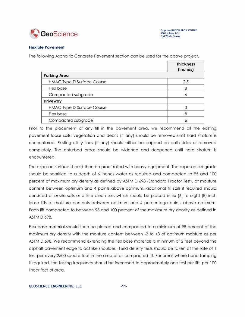
Flexible Pavement
The following Asphaltic Concrete Pavement section can be used for the above project.
Thickness
(inches)
Parking Area
HMAC Type D Surface Course 2.5
Flex base 8
Compacted subgrade 6
Driveway
HMAC Type D Surface Course 3
Flex base 8
Compacted subgrade 6
Prior to the placement of any fill in the pavement area, we recommend all the existing
pavement loose soils; vegetation and debris (if any) should be removed until hard stratum is
encountered. Existing utility lines (if any) should either be capped on both sides or removed
completely. The disturbed areas should be widened and deepened until hard stratum is
encountered.
The exposed surface should then be proof rolled with heavy equipment. The exposed subgrade
should be scarified to a depth of 6 inches water as required and compacted to 95 and 100
percent of maximum dry density as defined by ASTM D 698 (Standard Proctor Test), at moisture
content between optimum and 4 points above optimum. additional fill soils if required should
consisted of onsite soils or offsite clean soils which should be placed in six (6) to eight (8)-inch
loose lifts at moisture contents between optimum and 4 percentage points above optimum.
Each lift compacted to between 95 and 100 percent of the maximum dry density as defined in
ASTM D 698.
Flex base material should then be placed and compacted to a minimum of 98 percent of the
maximum dry density with the moisture content between -2 to +3 of optimum moisture as per
ASTM D 698. We recommend extending the flex base materials a minimum of 2 feet beyond the
asphalt pavement edge to act like shoulder. Field density tests should be taken at the rate of 1
test per every 2500 square foot in the area of all compacted fill. For areas where hand tamping
is required, the testing frequency should be increased to approximately one test per lift, per 100
linear feet of area.

Proposed DUTCH BROS. COFFEE
6301 N Beach St
Fort Worth, Texas
GEOSCIENCE ENGINEERING, LLC -12-
Prime coat should then be applied on all HMAC receiving areas to ensure proper bonding of the
asphalt surface.
Asphalt Type D should be placed, and roll compacted to a tight and smooth finish, the thickness
of the finished asphalt should be as recommended above. A full-time inspection by a
Geotechnical laboratory is required during placement of asphalt.
Proper drainage away from the pavement is the utmost importance to reduce water infiltration
into the subgrade. We recommend providing a gradual slope for proper surface water
drainage off of asphalt pavement. Water ponding should not be allowed to occur on or close
to the pavement surface.
The "design life" of a pavement is defined as the expected life at the end of which
reconstruction of the pavement will need to occur. Normal maintenance, including crack
sealing, slurry sealing, and/or chip sealing, should be performed during the life of the pavement.
Due to the high static loads imposed by parking trucks in loading and unloading areas and at
dumpster locations, we recommend that a rigid pavement section be considered for these
areas. Bituminous surfacing should be constructed of dense-graded, central plant-mix, asphalt
concrete. Base course, Portland cement, and asphalt concrete should conform with Texas
Department of Transportation. The pavement subgrade should be prepared as per the
recommendations provided in previous sections of this report. The gradient of paved surfaces
should ensure positive drainage. Water should not pond in areas directly adjoining paved
sections.
The asphalt pavement analysis was performed using the AASHTO design method and the
previously stated assumed traffic characteristics. The HMAC should meet the Department of
Transportation specifications.
SITE GRADING and DRAINAGE
All grading should provide positive drainage away from the proposed structures and should
prevent water from collecting or discharging near the foundations. Water must not be permitted
to pond adjacent to the structures during or after construction.
Surface drainage gradients should be designed to divert surface water away from the buildings
and edges of pavements and towards suitable collection and discharge facilities. Unpaved

Proposed DUTCH BROS. COFFEE
6301 N Beach St
Fort Worth, Texas
GEOSCIENCE ENGINEERING, LLC -13-
areas and permeable surfaces should be provided with steeper gradients than paved areas.
Pavement drainage gradients within 5 feet of buildings should be constructed with a minimum
slope of 1/4 inch per foot to prevent negative drainage gradients (ponding water conditions)
from developing due to differential upward pavement movements. Sidewalk drainage gradients
should be along maximum slopes allowed by local codes.
Roofs should be provided with gutters and downspouts to prevent the discharge of rainwater
directly onto the ground adjacent to the building foundations. Downspouts should not discharge
into any landscaped bed near the foundations. Downspouts should discharge directly into storm
drains or drainage swales, if possible. Roof downspouts and surface drain outlets should
discharge into erosion-resistant areas, such as paving or rock riprap. Recessed landscaped
areas filled with pervious sandy loam or organic soil should not be used near the foundation.
Landscaped beds should be elevated above a compacted and well-graded clay surface.
Sealed planters are preferred. All trees should be a minimum of one-half their mature height
away from the building or pavement edges to reduce potential moisture losses. Water permitted
to pond in planters, open areas, or areas with unsealed joints next to structures can result in
on-grade slab or pavement movements, which exceed those, indicated in this report.
Exterior sidewalks and pavements will be subject to some post construction movement as
indicated in this report. These potential movements should be considered during preparation of
the grading plan. Flat grades should be avoided. Where concrete pavement is used, joints
should be sealed to prevent the infiltration of water. Some post-construction movement of
pavement and flatwork may occur. Particular attention should be given to joints around the
building. These joints should be periodically inspected and resealed where necessary. It should
be noted that due to deeper depth of fill soils some settling of the fill soils may occur in future.
CLOSURE
It should be noted that some variations in soil and moisture conditions may exist between boring
locations. Statements in this report as to subsurface variations over given areas are intended as
estimations only, based upon the data obtained from specific boring locations.
The results, conclusions, and recommendations contained in this report are directed at, and
intended to be utilized within the scope of work outlined in this report. The report is not intended
for use in any other manner. Geoscience Engineers, LLC., makes no claim or representation
concerning any activity or condition falling outside the specified purposes for which this report is

Proposed DUTCH BROS. COFFEE
6301 N Beach St
Fort Worth, Texas
GEOSCIENCE ENGINEERING, LLC -14-
directed; said purposes being specifically limited to the scope of work as defined herein.
Inquiries regarding scope of work, activities and/or conditions not specifically outlined herein,
should be directed to Geoscience Engineers, LLC.

Proposed DUTCH BROS. COFFEE
6301 N Beach St
Fort Worth, Texas
GEOSCIENCE ENGINEERING, LLC
ILLUSTRATIONS

Proposed DUTCH BROS. COFFEE
6301 N Beach St
Fort Worth, Texas
GEOSCIENCE ENGINEERING, LLC
Geoscience Project No.: 21-DG6556 Plate A
BORING LOCATION PLAN
Proposed DUTCH BROS. COFFEE-TX0507
6301 N beach St
Fort Worth, Texas

0
5
10
15
20
25
30
P4.5+
P4.5+
P4.5+
P4.0
P4.0
6
13
20
Dark brown CLAY (CH) with a trace of calcareousnodules
Tan and brown SANDY CLAY (CL) with a trace ofcalcareous nodules
Tan SANDY CLAY (CL) with gravel
14
23
22
18
19
21
18
61
44
31
23
18
16
38
26
15
98
104
1.7
2.6
74
51
LOG OF BORING NO. B-1Proposed "DUTCH BROS.COFFEE-TX0507"
6301 N Beach StFort Worth, Texas
Project No. 21-DG6556
REMARKS:
TUBESAMPLE
AUGERSAMPLE
SPLIT-SPOON
ROCKCORE
THDCONEPEN.
NORECOVERY
DE
PT
H (
ft.)
FIELD DATA
SO
IL &
RO
CK
SY
MB
OL
SA
MP
LE
TY
PE
P: H
AN
D P
EN
., T
SF
T: T
HD
, B
LO
WS
/FT
.
N: S
PT
, B
LO
WS
/FT
.
ST
RA
TU
M D
EP
TH
(FT
.)
DESCRIPTION OF STRATUM
Location: See Location Plan
Surface Elevation: Unknown
Drilling Method: CFA
Date Boring Drilled: 07/29/2021
Completion Depth: 20
Groundwater Information:
Seepage Encountered During Drilling: None
Upon Completion: Dry
WA
TE
R C
ON
TE
NT
, %
LABORATORY DATA
LIQ
UID
LIM
IT
PL
AS
TIC
LIM
IT
PL
AS
TIC
ITY
IN
DE
X
UN
IT D
RY
WE
IGH
T
(PC
F)
UN
CO
NF
INE
D
ST
RE
NG
TH
(TS
F)
% P
AS
SIN
G N
O. 2
00
SIE
VE
SO
IL S
UC
TIO
N T
ES
T
(TO
TA
L C
M. O
F
WA
TE
R)
Plate 1Geoscience Engineering & Testing

0
5
10
15
20
25
30
P4.5+
P4.5+
P4.5+
P4.5+
P4.5+
0.41
2
5
10
Concrete - 5"
Dark brown CLAY (CH) with a trace of calcareousnodules
Tan and brown SANDY CLAY (CL) with a trace ofcalcareous nodules
Tan SANDY CLAY (CL) with gravel
13
12
12
5
8
52
40
22
18
30
22 115 2.9 53
LOG OF BORING NO. B-2Proposed "DUTCH BROS.COFFEE-TX0507"
6301 N Beach StFort Worth, Texas
Project No. 21-DG6556
REMARKS:
TUBESAMPLE
AUGERSAMPLE
SPLIT-SPOON
ROCKCORE
THDCONEPEN.
NORECOVERY
DE
PT
H (
ft.)
FIELD DATA
SO
IL &
RO
CK
SY
MB
OL
SA
MP
LE
TY
PE
P: H
AN
D P
EN
., T
SF
T: T
HD
, B
LO
WS
/FT
.
N: S
PT
, B
LO
WS
/FT
.
ST
RA
TU
M D
EP
TH
(FT
.)
DESCRIPTION OF STRATUM
Location: See Location Plan
Surface Elevation: Unknown
Drilling Method: CFA
Date Boring Drilled: 07/29/2021
Completion Depth: 10
Groundwater Information:
Seepage Encountered During Drilling: None
Upon Completion: Dry
WA
TE
R C
ON
TE
NT
, %
LABORATORY DATA
LIQ
UID
LIM
IT
PL
AS
TIC
LIM
IT
PL
AS
TIC
ITY
IN
DE
X
UN
IT D
RY
WE
IGH
T
(PC
F)
UN
CO
NF
INE
D
ST
RE
NG
TH
(TS
F)
% P
AS
SIN
G N
O. 2
00
SIE
VE
SO
IL S
UC
TIO
N T
ES
T
(TO
TA
L C
M. O
F
WA
TE
R)
Plate 2Geoscience Engineering & Testing
0
5
10
15
20
25
30
P4.5+
P4.5+
P4.5+
P4.5+
P4.5+
2
5
10
Dark brown CLAY (CH) with a trace of calcareousnodules
Tan and brown SANDY CLAY (CL) with a trace ofcalcareous nodules
Tan SANDY CLAY (CL) with gravel
15
15
14
16
10
43 18 25
110
LOG OF BORING NO. B-3Proposed "DUTCH BROS.COFFEE-TX0507"
6301 N Beach StFort Worth, Texas
Project No. 21-DG6556
REMARKS:
TUBESAMPLE
AUGERSAMPLE
SPLIT-SPOON
ROCKCORE
THDCONEPEN.
NORECOVERY
DE
PT
H (
ft.)
FIELD DATA
SO
IL &
RO
CK
SY
MB
OL
SA
MP
LE
TY
PE
P: H
AN
D P
EN
., T
SF
T: T
HD
, B
LO
WS
/FT
.
N: S
PT
, B
LO
WS
/FT
.
ST
RA
TU
M D
EP
TH
(FT
.)
DESCRIPTION OF STRATUM
Location: See Location Plan
Surface Elevation: Unknown
Drilling Method: CFA
Date Boring Drilled: 07/29/2021
Completion Depth: 10
Groundwater Information:
Seepage Encountered During Drilling: None
Upon Completion: Dry
WA
TE
R C
ON
TE
NT
, %
LABORATORY DATA
LIQ
UID
LIM
IT
PL
AS
TIC
LIM
IT
PL
AS
TIC
ITY
IN
DE
X
UN
IT D
RY
WE
IGH
T
(PC
F)
UN
CO
NF
INE
D
ST
RE
NG
TH
(TS
F)
% P
AS
SIN
G N
O. 2
00
SIE
VE
SO
IL S
UC
TIO
N T
ES
T
(TO
TA
L C
M. O
F
WA
TE
R)
Plate 3Geoscience Engineering & Testing

0
5
10
15
20
25
30
P4.5+
P4.5+
P2.0
Dark brown CLAY (CH) with a trace of calcareousnodules
21
19
24 53 19 34 94
LOG OF BORING NO. B-4Proposed "DUTCH BROS.COFFEE-TX0507"
6301 N Beach StFort Worth, Texas
Project No. 21-DG6556
REMARKS:
TUBESAMPLE
AUGERSAMPLE
SPLIT-SPOON
ROCKCORE
THDCONEPEN.
NORECOVERY
DE
PT
H (
ft.)
FIELD DATA
SO
IL &
RO
CK
SY
MB
OL
SA
MP
LE
TY
PE
P: H
AN
D P
EN
., T
SF
T: T
HD
, B
LO
WS
/FT
.
N: S
PT
, B
LO
WS
/FT
.
ST
RA
TU
M D
EP
TH
(FT
.)
DESCRIPTION OF STRATUM
Location: See Location Plan
Surface Elevation: Unknown
Drilling Method: CFA
Date Boring Drilled: 07/29/2021
Completion Depth: 6
Groundwater Information:
Seepage Encountered During Drilling: None
Upon Completion: Dry
WA
TE
R C
ON
TE
NT
, %
LABORATORY DATA
LIQ
UID
LIM
IT
PL
AS
TIC
LIM
IT
PL
AS
TIC
ITY
IN
DE
X
UN
IT D
RY
WE
IGH
T
(PC
F)
UN
CO
NF
INE
D
ST
RE
NG
TH
(TS
F)
% P
AS
SIN
G N
O. 2
00
SIE
VE
SO
IL S
UC
TIO
N T
ES
T
(TO
TA
L C
M. O
F
WA
TE
R)
Plate 4Geoscience Engineering & Testing

Proposed DUTCH BROS. COFFEE
6301 N Beach St
Fort Worth, Texas
GEOSCIENCE ENGINEERING, LLC
Proposed DUTCH BROS. COFFEE-TX0507
6301 N Beach St
Fort Worth, Texas
SUMMARY OF FREE SWELL TESTS
Boring Number B-1
Sample Depth (ft.) 2-4
Initial Moisture Content (%) 23
Final Moisture Content (%) 29
Applied Surcharge Pressure (psf) 375
Vertical Swell (%) 3.3
Liquid Limit 61
Plastic Limit 23
Plasticity Index 38
Plate 5