Embed Size (px)
Citation preview
GEOTECHNICAL INVESTIGATION SOUTHWOOD 3 AND SOUTHWOOD RESIDENTIAL SUBDIVISION 1143 LISTOWEL ROAD, ELMIRA, ONTARIO
for
BIRDLAND DEVELOPMENTS LIMITED c/o WALTERFEDY PETO MacCALLUM LTD. 16 FRANKLIN STREET SOUTH KITCHENER, ONTARIO N2C 1R4 PHONE: (519) 893-7500 FAX: (519) 893-0654 EMAIL: [email protected] Distribution: PML Ref.: 12KF071 10 cc: WaterFedy (+ email) Report: 4 1 cc: PML Kitchener April 25, 2014
16 Franklin Street South, Kitchener, Ontario N2C 1R4
Tel: (519) 893-7500 Fax: (519) 893-0654
E-mail: [email protected]
BARRIE, HAMILTON, KITCHENER, TORONTO
April 25, 2014 PML Ref.: 12KF071 Report: 4 Birdland Developments Limited c/o Mr. Scott Oliver, P.Eng. WalterFedy 675 Queen Street South, Suite 111 Kitchener, Ontario N2M 1A1 Dear Mr. Oliver Geotechnical Investigation Southwood 3 Residential Subdivision Additional Lands South Parkwood Boulevard Elmira, Ontario
Peto MacCallum Ltd. (PML) was retained by WalterFedy to carry out a program of
hydrogeological and geotechnical investigations in support of a proposed land development on a
41.9 ha (approximate) parcel of land located at 1143 Listowel Road in Elmira, Ontario (referred to
herein as the ‘site’). Authorization to proceed with this assignment was received from Mr. Oliver
of WalterFedy via email messages.
The terms of reference for this assignment included a combined geotechnical / hydrogeological
investigation for the parcel of land. This report presents only the geotechnical findings and
recommendations. Reference is made to Report 3 for the findings of the hydrogeological site
assessment which was completed simultaneously to this report. It is noted that several phases of
investigatory work have been completed for this assignment, with geotechnical results previously
presented in Reports 1 and 2. This report provides geotechnical recommendations for the entire
development and as such, supersedes any geotechnical recommendations provided previously.
Geotechnical Investigation, Southwood 3 and Southwood 4 Residential Subdivision PML Ref.: 12KF071, Report: 4 April 25, 2014, Page 2
Project Description
The subject site is located on the north side of Listowel Road, south of Whippoorwill Drive and is
bounded by South Parkwood Boulevard to the east and a municipal drainage ditch to the west.
PML understands that the proposed residential subdivision development will be completed in two
phases (namely Southwood 3 and Southwood 4) as depicted on Drawings DP-1 and DP-2
(provided by the client) dated December 13 and December 2, 2013 respectively. Pertinent details
of the proposed development are depicted on the attached Drawing 1, Borehole and Monitoring
Well Location Plan.
The first phase of development, as shown on DP-1 (i.e. Southwood 3), will include approximately
6.1 ha of single detached, semi-detached and townhouse residential units with three streets in the
northeastern portion of the site along with a parkland or forested land space to the north and a
storm water management (SWM) pond located near the southern portion of the site. The second
phase of development, as shown on DP-2 (Southwood 4), will include approximately 13.6 ha of
single detached, semi-detached and townhouse residential units, with an additional 2.5 ha area
set aside for multiple residential buildings and will include the construction of six streets in the
western and southeastern portions of the site. The Southwood 4 development will include the
reconstruction or enlargement of the SWM pond constructed during the Southwood 3 works.
The purpose of the geotechnical investigation was to explore the subsurface soil and ground
water conditions within the site area. Based on the findings, geotechnical design and construction
recommendations were to be provided. Specific considerations to be addressed included:
• Existing geological setting, site description and subsurface conditions (soils and
ground water);
• Site preparation and grading, including topsoil thickness to be stripped, material
reusability and engineered fill construction requirements;
• Preliminary foundation design parameters for structures, identification of areas where
conventional footing and basement construction might not be feasible and
recommended foundation options for such areas;
Geotechnical Investigation, Southwood 3 and Southwood 4 Residential Subdivision PML Ref.: 12KF071, Report: 4 April 25, 2014, Page 3
• Excavation and backfilling, including construction dewatering, safe slope inclination,
suitability of native soils for reuse as backfill, and compaction requirements;
• Site servicing (storm, sanitary, water and utilities), including bedding requirements;
• Structural pavement designs for internal roadways; and,
• Geotechnical design parameters for the SWM facility.
The recommendations provided in this report are for design purposes only. When the project
design is complete, the general recommendations given in this report should be reviewed to
ensure their applicability.
An environmental assessment of the soil and ground water was not included within the terms of
reference for this assignment and no work has been carried out in that regard. A concurrent
hydrogeological study of the site is being carried out by PML, for which a separate report will be
issued.
Investigation Procedure
The field work for the geotechnical investigation was completed in three stages (January 7 to 11,
2013, October 10 and 11, 2013 and February 18 to 24, 2014) concurrently with the
hydrogeological study. Boreholes were drilled at twenty two locations (BH1 through BH22) for soil
sampling and included the installation of a total of twenty-nine monitoring wells for ground water
monitoring, testing and sampling. Nested wells comprising two 50 mm diameter monitoring wells
at a single borehole location were installed in fourteen boreholes as shown on Drawing 1, with a
single monitoring well installed at Borehole 13.
The boreholes were advanced using a Diedrich D-50 track mounted drillrig equipped with
continuous flight hollow stem augers. The drilling equipment was supplied and operated by a
specialist drilling contractor working under subcontract to PML.
Geotechnical Investigation, Southwood 3 and Southwood 4 Residential Subdivision PML Ref.: 12KF071, Report: 4 April 25, 2014, Page 4
Representative samples of the overburden were recovered at regular intervals throughout the
depths explored. Standard penetration tests were carried out during sampling operations using
conventional split spoon equipment. Ground water observations were made in the boreholes and
observation wells during and upon completion of drilling.
The field work was supervised throughout by a member of PML’s engineering staff who directed
the drilling and sampling operation, prepared the stratigraphic logs, monitored ground water
conditions, and processed the recovered samples.
The borehole locations were determined in the field by PML for coverage of the proposed works.
Reference is made to Drawing 1 attached for the borehole locations as well as the proposed
development works. Boreholes BH1 to BH11 were located throughout the Southwood 3 area and
the central / west areas of Southwood 4 and were advanced in January, 2013, BH12 to BH14
were located in the northern portion of Southwood 4 and were advanced in October 2013, and
BH15 to BH22 were located throughout the southern portion of Southwood 4 and the proposed
SWM pond areas, and were advanced in February 2014.
The survey was completed partially by WalterFedy (BH1 to BH11) and partially by PML (BH12 to
BH22). The surface elevations at BH12 to BH22 were referenced to the following temporary
benchmarks (TBM), provided by WalterFedy during the previous investigation:
TBM1: Top of BH/MW 9 Stand Pipe
Elevation: 365.25 (geodetic, metric) TBM2: Top of BH/MW 11 Stand Pipe
Elevation: 364.20 (geodetic, metric) TBM3: Iron bar at southwest corner of property
Elevation: 365.15 (geodetic, metric)
It should be noted that decommissioning of the monitoring wells as required under O.Reg. 903
was not included within PML's terms of reference for this assignment and future decommissioning
will be required for the monitoring wells.
Geotechnical Investigation, Southwood 3 and Southwood 4 Residential Subdivision PML Ref.: 12KF071, Report: 4 April 25, 2014, Page 5
All soil samples collected during the investigation were returned to PML’s laboratory for detailed
visual examination and testing. The geotechnical testing program included moisture content
determinations on recovered samples and eleven particle size distribution analyses carried out to
assist with soil classifications for construction dewatering purposes and modelling of the
hydrogeological setting of the site.
Subsurface Conditions
Reference is made to the appended Log of Borehole sheets for details of the field work including
soil descriptions, inferred stratigraphy, standard penetration test (SPT) N values, ground water
observations, laboratory moisture content determinations and results of the particle size
distribution analyses.
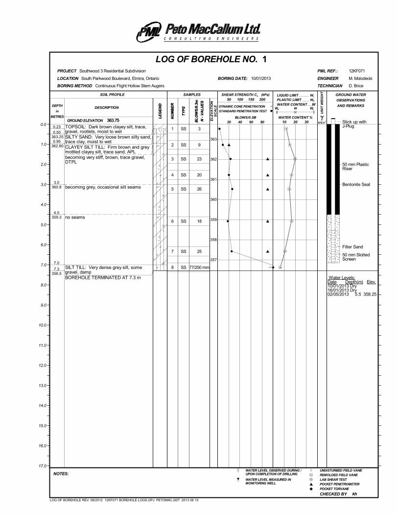
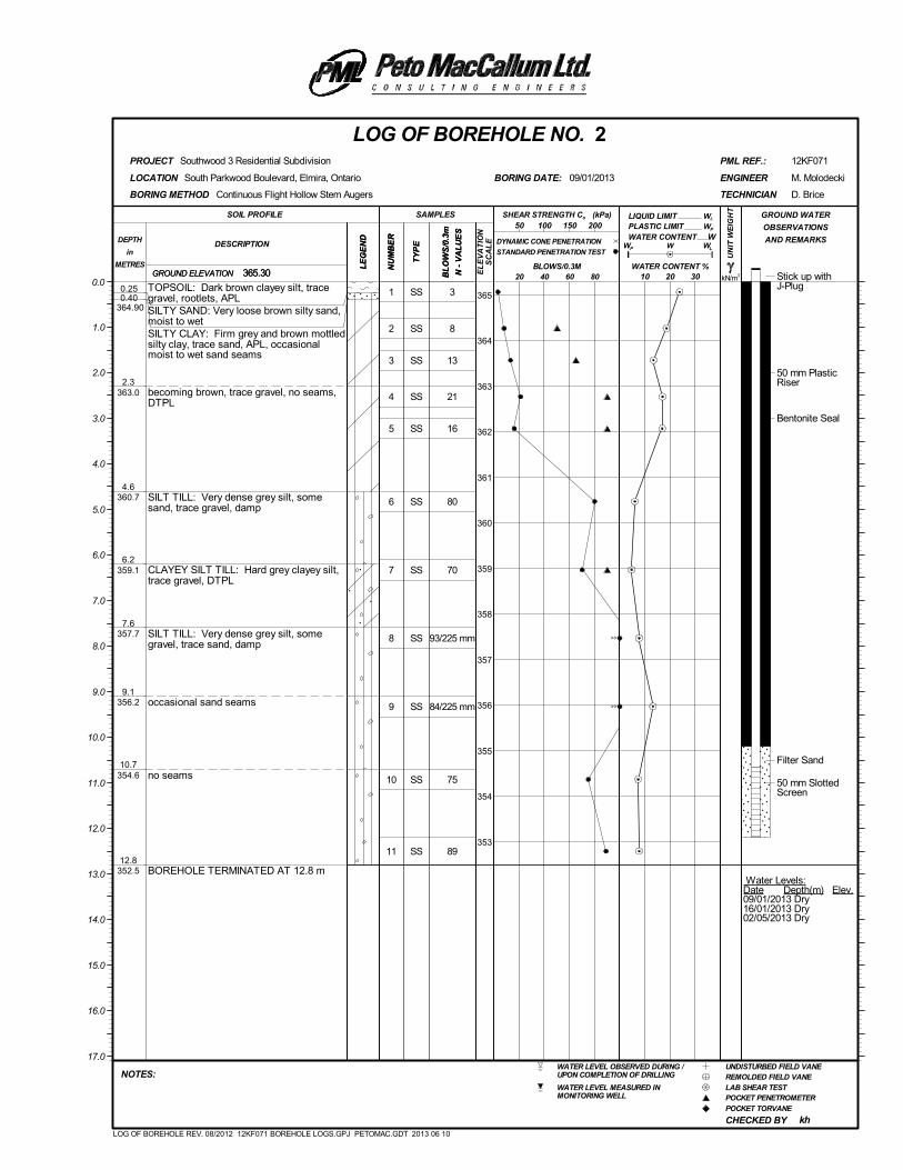
In general, the subsurface conditions encountered at the borehole locations consist of topsoil
overlying silty sand, silty clay and / or a major glacial till deposit of clayey silt and silt.
Topsoil
Dark brown clayey silt topsoil was contacted from the surface in all of the boreholes. Between
200 and 800 mm of topsoil was penetrated, and was typically described as moist, dark brown
clayey silt, trace gravel with rootlets.
Silty Sand
Immediately underlying the topsoil in BH1, BH2, BH3, BH6 and BH7, a thin, discontinuous layer of
loose silty sand was contacted, extending to a maximum observed depth of 0.86 m.
Geotechnical Investigation, Southwood 3 and Southwood 4 Residential Subdivision PML Ref.: 12KF071, Report: 4 April 25, 2014, Page 6
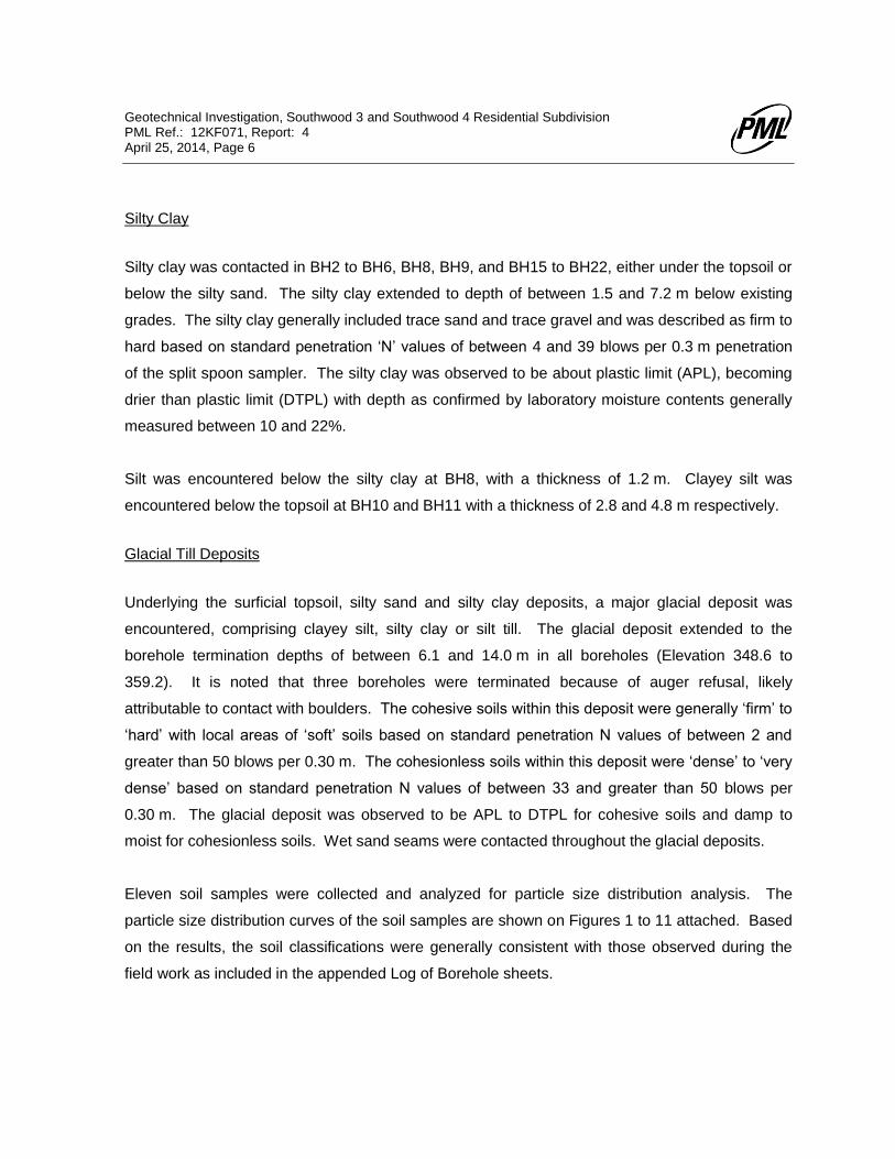
Silty Clay
Silty clay was contacted in BH2 to BH6, BH8, BH9, and BH15 to BH22, either under the topsoil or
below the silty sand. The silty clay extended to depth of between 1.5 and 7.2 m below existing
grades. The silty clay generally included trace sand and trace gravel and was described as firm to
hard based on standard penetration ‘N’ values of between 4 and 39 blows per 0.3 m penetration
of the split spoon sampler. The silty clay was observed to be about plastic limit (APL), becoming
drier than plastic limit (DTPL) with depth as confirmed by laboratory moisture contents generally
measured between 10 and 22%.
Silt was encountered below the silty clay at BH8, with a thickness of 1.2 m. Clayey silt was
encountered below the topsoil at BH10 and BH11 with a thickness of 2.8 and 4.8 m respectively.
Glacial Till Deposits
Underlying the surficial topsoil, silty sand and silty clay deposits, a major glacial deposit was
encountered, comprising clayey silt, silty clay or silt till. The glacial deposit extended to the
borehole termination depths of between 6.1 and 14.0 m in all boreholes (Elevation 348.6 to
359.2). It is noted that three boreholes were terminated because of auger refusal, likely
attributable to contact with boulders. The cohesive soils within this deposit were generally ‘firm’ to
‘hard’ with local areas of ‘soft’ soils based on standard penetration N values of between 2 and
greater than 50 blows per 0.30 m. The cohesionless soils within this deposit were ‘dense’ to ‘very
dense’ based on standard penetration N values of between 33 and greater than 50 blows per
0.30 m. The glacial deposit was observed to be APL to DTPL for cohesive soils and damp to
moist for cohesionless soils. Wet sand seams were contacted throughout the glacial deposits.
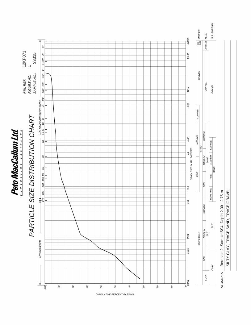
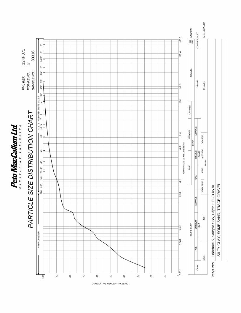
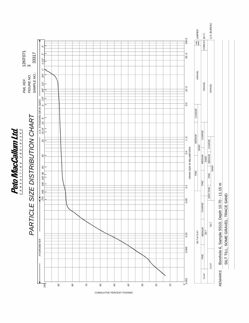
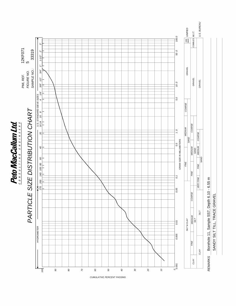
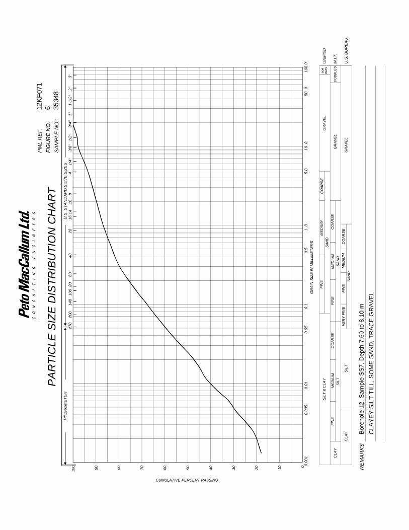
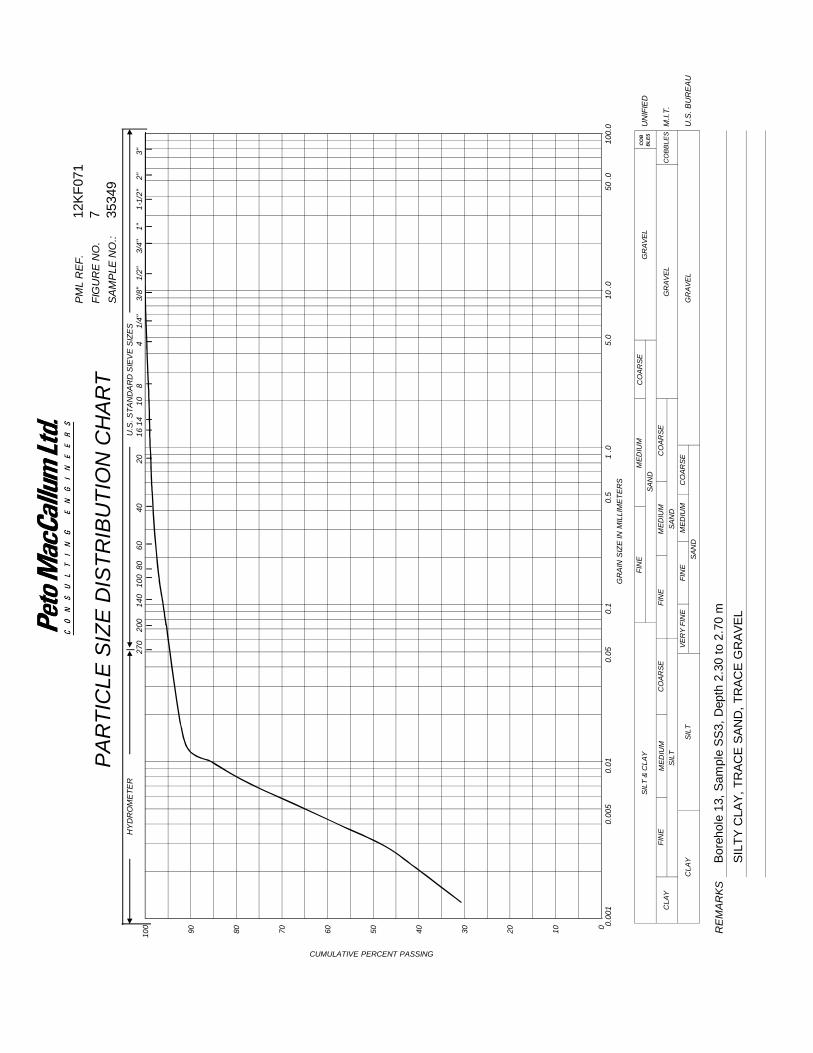
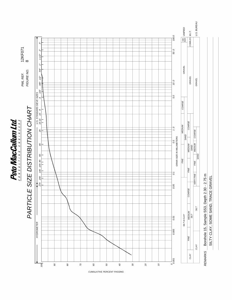
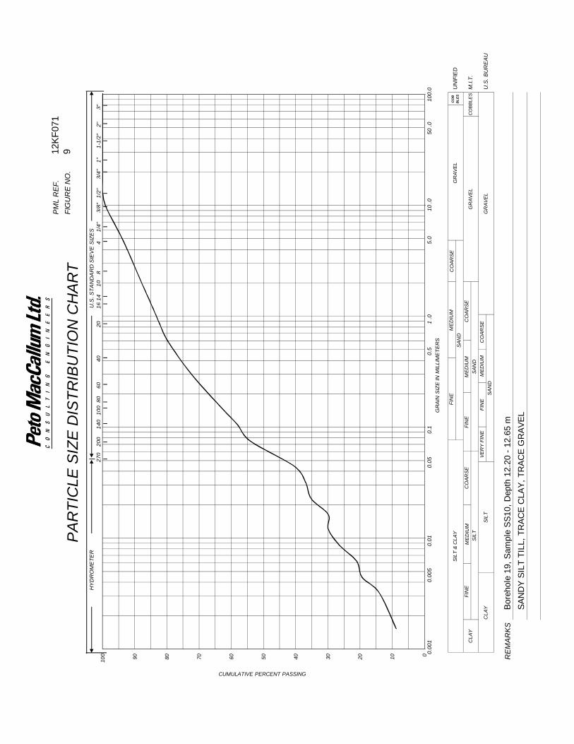
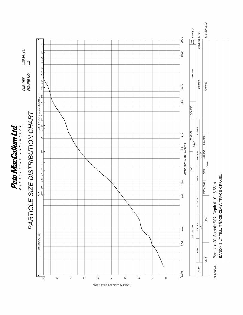
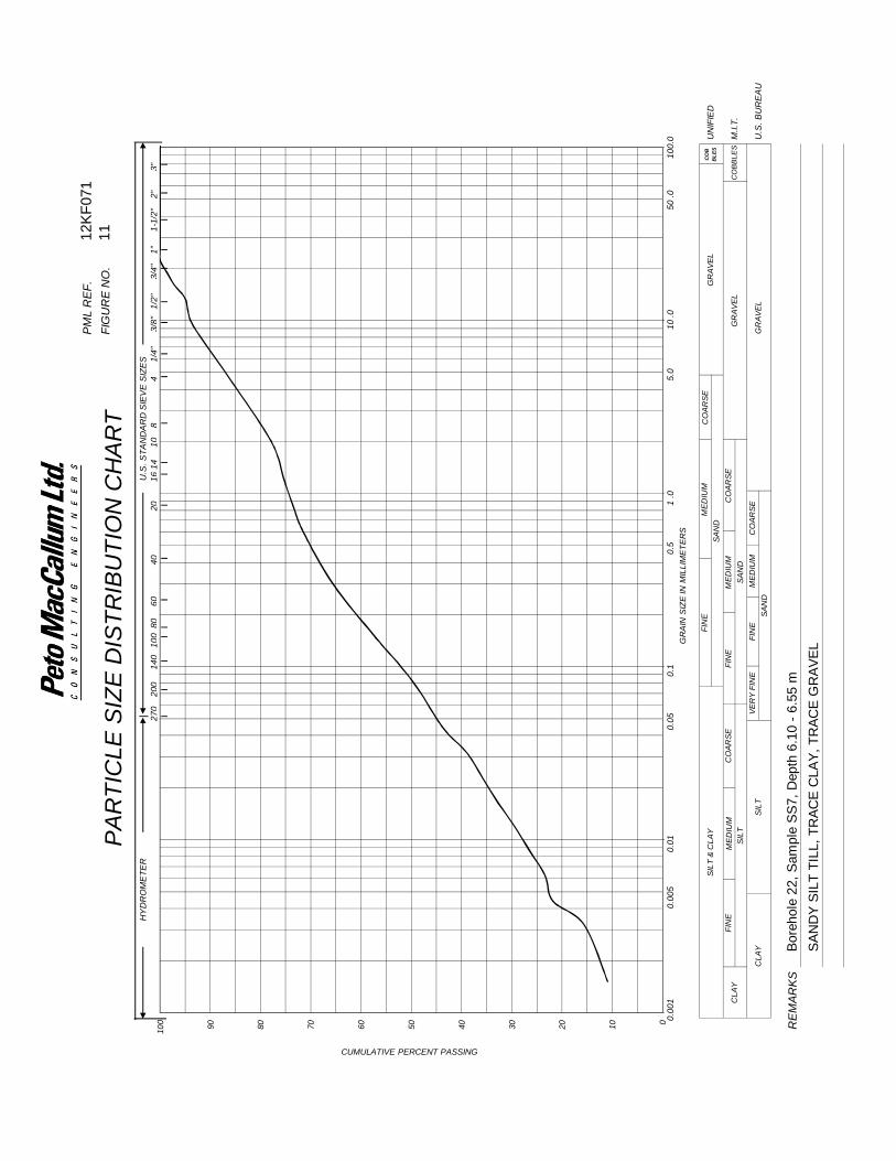
Eleven soil samples were collected and analyzed for particle size distribution analysis. The
particle size distribution curves of the soil samples are shown on Figures 1 to 11 attached. Based
on the results, the soil classifications were generally consistent with those observed during the
field work as included in the appended Log of Borehole sheets.
Geotechnical Investigation, Southwood 3 and Southwood 4 Residential Subdivision PML Ref.: 12KF071, Report: 4 April 25, 2014, Page 7
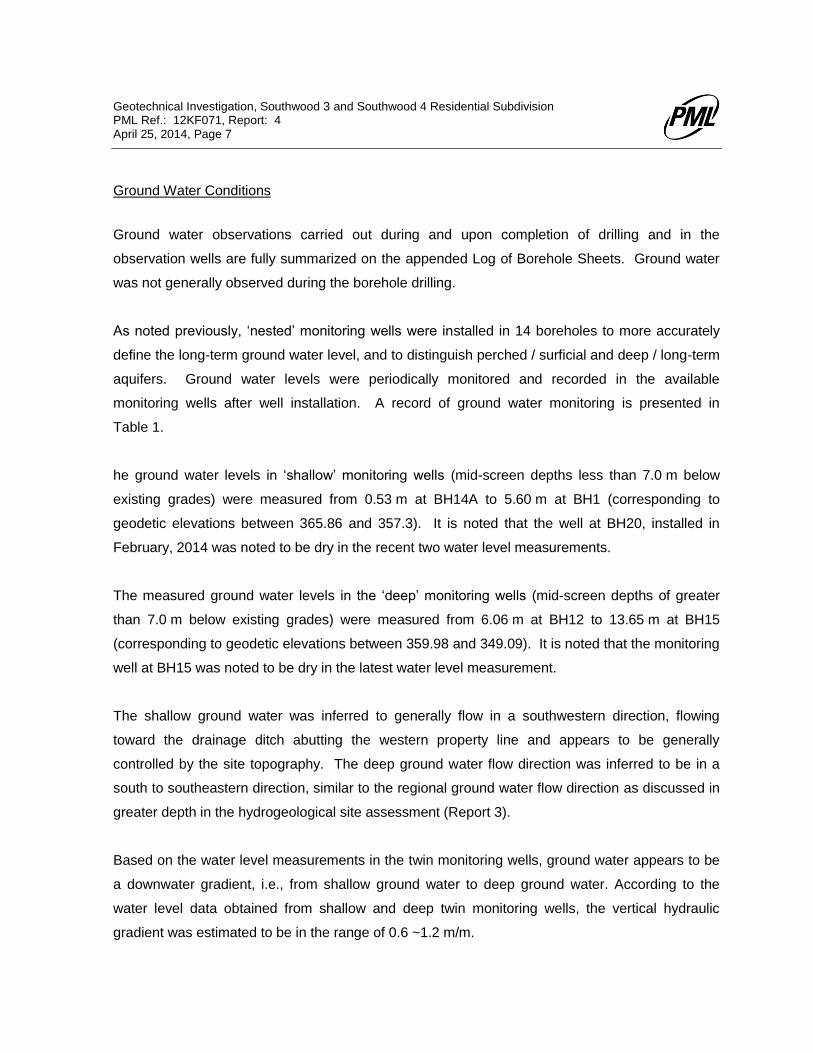
Ground Water Conditions
Ground water observations carried out during and upon completion of drilling and in the
observation wells are fully summarized on the appended Log of Borehole Sheets. Ground water
was not generally observed during the borehole drilling.
As noted previously, ‘nested’ monitoring wells were installed in 14 boreholes to more accurately
define the long-term ground water level, and to distinguish perched / surficial and deep / long-term
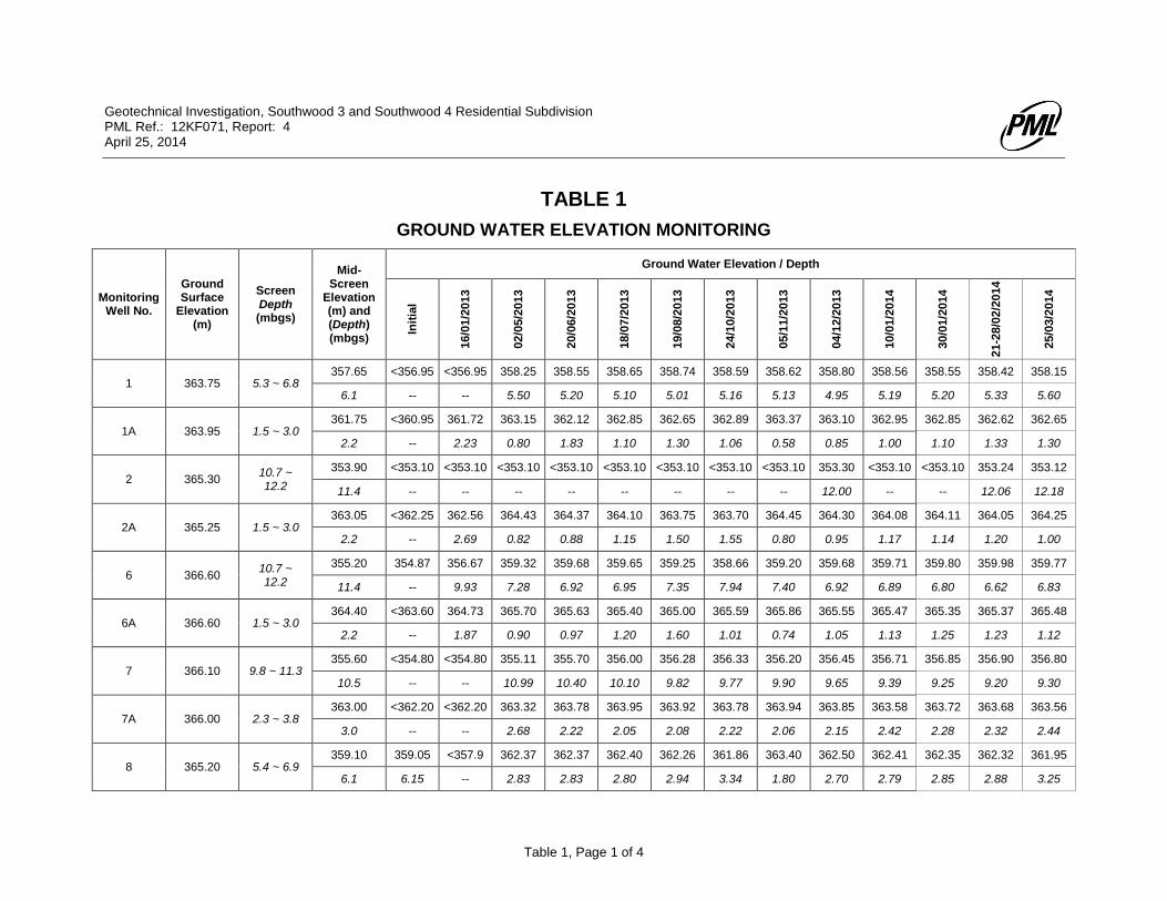
aquifers. Ground water levels were periodically monitored and recorded in the available
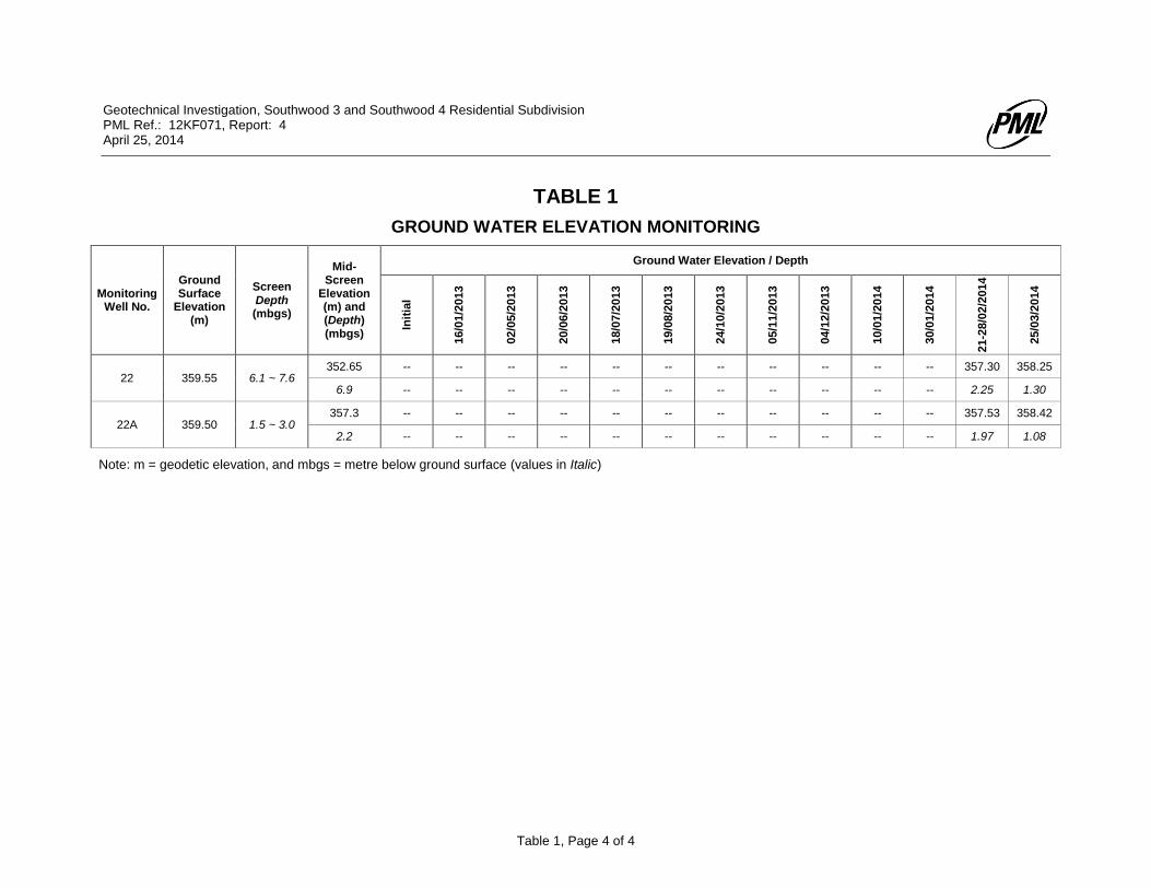
monitoring wells after well installation. A record of ground water monitoring is presented in
Table 1.
he ground water levels in ‘shallow’ monitoring wells (mid-screen depths less than 7.0 m below
existing grades) were measured from 0.53 m at BH14A to 5.60 m at BH1 (corresponding to
geodetic elevations between 365.86 and 357.3). It is noted that the well at BH20, installed in
February, 2014 was noted to be dry in the recent two water level measurements.
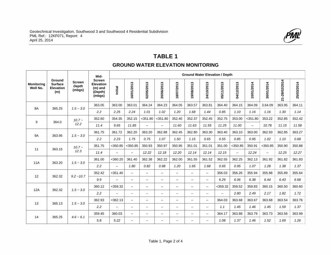
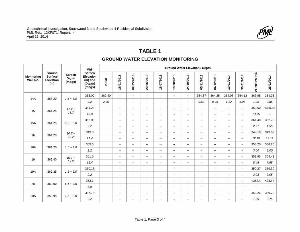
The measured ground water levels in the ‘deep’ monitoring wells (mid-screen depths of greater
than 7.0 m below existing grades) were measured from 6.06 m at BH12 to 13.65 m at BH15
(corresponding to geodetic elevations between 359.98 and 349.09). It is noted that the monitoring
well at BH15 was noted to be dry in the latest water level measurement.
The shallow ground water was inferred to generally flow in a southwestern direction, flowing
toward the drainage ditch abutting the western property line and appears to be generally
controlled by the site topography. The deep ground water flow direction was inferred to be in a
south to southeastern direction, similar to the regional ground water flow direction as discussed in
greater depth in the hydrogeological site assessment (Report 3).
Based on the water level measurements in the twin monitoring wells, ground water appears to be
a downwater gradient, i.e., from shallow ground water to deep ground water. According to the
water level data obtained from shallow and deep twin monitoring wells, the vertical hydraulic
gradient was estimated to be in the range of 0.6 ~1.2 m/m.
Geotechnical Investigation, Southwood 3 and Southwood 4 Residential Subdivision PML Ref.: 12KF071, Report: 4 April 25, 2014, Page 8
The ground water levels (particularly the shallow ground water) at the site are subject to change
due to seasonal fluctuations and major precipitation events. The relatively impermeable nature of
the silty clay / clayey silt till may contribute to the development of perched water conditions
following short term and seasonal precipitation events.
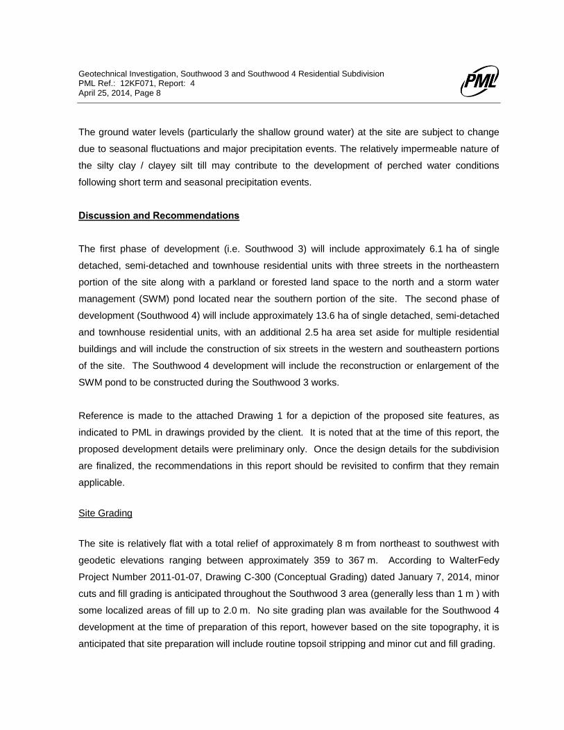
Discussion and Recommendations
The first phase of development (i.e. Southwood 3) will include approximately 6.1 ha of single
detached, semi-detached and townhouse residential units with three streets in the northeastern
portion of the site along with a parkland or forested land space to the north and a storm water
management (SWM) pond located near the southern portion of the site. The second phase of
development (Southwood 4) will include approximately 13.6 ha of single detached, semi-detached
and townhouse residential units, with an additional 2.5 ha area set aside for multiple residential
buildings and will include the construction of six streets in the western and southeastern portions
of the site. The Southwood 4 development will include the reconstruction or enlargement of the
SWM pond to be constructed during the Southwood 3 works.
Reference is made to the attached Drawing 1 for a depiction of the proposed site features, as
indicated to PML in drawings provided by the client. It is noted that at the time of this report, the
proposed development details were preliminary only. Once the design details for the subdivision
are finalized, the recommendations in this report should be revisited to confirm that they remain
applicable.
Site Grading
The site is relatively flat with a total relief of approximately 8 m from northeast to southwest with
geodetic elevations ranging between approximately 359 to 367 m. According to WalterFedy
Project Number 2011-01-07, Drawing C-300 (Conceptual Grading) dated January 7, 2014, minor
cuts and fill grading is anticipated throughout the Southwood 3 area (generally less than 1 m ) with
some localized areas of fill up to 2.0 m. No site grading plan was available for the Southwood 4
development at the time of preparation of this report, however based on the site topography, it is
anticipated that site preparation will include routine topsoil stripping and minor cut and fill grading.
Geotechnical Investigation, Southwood 3 and Southwood 4 Residential Subdivision PML Ref.: 12KF071, Report: 4 April 25, 2014, Page 9
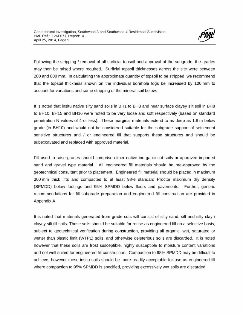
Following the stripping / removal of all surficial topsoil and approval of the subgrade, the grades
may then be raised where required. Surficial topsoil thicknesses across the site were between
200 and 800 mm. In calculating the approximate quantity of topsoil to be stripped, we recommend
that the topsoil thickness shown on the individual borehole logs be increased by 100 mm to
account for variations and some stripping of the mineral soil below.
It is noted that insitu native silty sand soils in BH1 to BH3 and near surface clayey silt soil in BH8
to BH10, BH15 and BH16 were noted to be very loose and soft respectively (based on standard
penetration N values of 4 or less). These marginal materials extend to as deep as 1.8 m below
grade (in BH10) and would not be considered suitable for the subgrade support of settlement
sensitive structures and / or engineered fill that supports these structures and should be
subexcavated and replaced with approved material.
Fill used to raise grades should comprise either native inorganic cut soils or approved imported
sand and gravel type material. All engineered fill materials should be pre-approved by the
geotechnical consultant prior to placement. Engineered fill material should be placed in maximum
300 mm thick lifts and compacted to at least 98% standard Proctor maximum dry density
(SPMDD) below footings and 95% SPMDD below floors and pavements. Further, generic
recommendations for fill subgrade preparation and engineered fill construction are provided in
Appendix A.
It is noted that materials generated from grade cuts will consist of silty sand, silt and silty clay /
clayey silt till soils. These soils should be suitable for reuse as engineered fill on a selective basis,
subject to geotechnical verification during construction, providing all organic, wet, saturated or
wetter than plastic limit (WTPL) soils, and otherwise deleterious soils are discarded. It is noted
however that these soils are frost susceptible, highly susceptible to moisture content variations
and not well suited for engineered fill construction. Compaction to 98% SPMDD may be difficult to
achieve, however these insitu soils should be more readily acceptable for use as engineered fill
where compaction to 95% SPMDD is specified, providing excessively wet soils are discarded.
Geotechnical Investigation, Southwood 3 and Southwood 4 Residential Subdivision PML Ref.: 12KF071, Report: 4 April 25, 2014, Page 10
Settlement of on site soils due to the surcharge of site grading fills is not expected to be of
concern, provided the above mentioned areas of weak subgrade soil are subexcavated prior to fill
placement.
Housing Construction
Based on Drawings DP-1 and DP-2 (provided by the client), building construction is not planned
for the southwestern portion of the site where a SWM pond is to be located (BH11, BH16 to
BH20). The following building construction recommendations are not applicable to that southern
area. It is anticipated that basements will be constructed for the planned residential units.
Based on the investigation findings, the native inorganic soils are typically suitable to support the
proposed buildings on conventional strip footings. The surficial topsoil should be completely
subexcavated from within the proposed building envelopes. As noted previously, the existing very
loose / soft native soils contacted locally within the surficial 1.5 m are not considered suitable for
the support of foundations. These localized soils should be completely subexcavated from within
the proposed building envelopes. For preliminary design purposes, footings founded in the
competent native deposits (at or below the depths provided in the table below) may be designed
for a net bearing resistance of 150 kPa at the serviceability limit state (SLS) and a factored
bearing resistance of 225 kPa at the ultimate limit state (ULS). Accordingly, footings designed in
accordance with the Ontario Building Code for residential housing will be satisfactory. The
following table summarizes the minimum foundation depths based on the borehole findings:
Geotechnical Investigation, Southwood 3 and Southwood 4 Residential Subdivision PML Ref.: 12KF071, Report: 4 April 25, 2014, Page 11
LOCATION MINIMUM
FOUNDATION DEPTH (m)
CORRESPONDING ELEVATION
(METRIC, GEODETIC) SOIL TYPE
BH1 0.6 363.15 Clayey silt till, trace sand
BH2 0.6 364.70 Silty clay, trace sand
BH3 0.7 364.20 Silty clay, trace gravel
BH4 1.5 364.50 Silty clay, trace sand
BH5 1.5 364.45 Silty clay, trace gravel
BH6 0.7 365.90 Silty clay, trace gravel
BH7 1.5 364.60 Clayey silt till, trace gravel
BH8 1.5 363.70 Silty clay, some sand
BH9 1.5 362.50 Silty clay
BH10 1.8 361.10 Clayey silt
BH12 1.5 360.80 Silty clay, trace sand, trace gravel
BH13 0.9 364.23 Silty clay, trace sand, trace gravel
BH14 1.5 363.75 Silty clay, trace sand, trace gravel
BH16 1.5 359.70 Silty clay, trace sand
BH19 0.8 361.60 Silty clay, trace gravel
Although in general, footings are anticipated to be placed on native insitu soils, where required the
footings may be supported on engineered structural fill, placed in accordance with the generic
recommendations for engineered fill construction provided in Appendix A. Prior to placement of
engineered fill, the soils should be subexcavated to competent native overburden soils (same
depths as table above). For engineered fill supporting footing loads, compaction to a minimum
98% of the materials SPMDD, should be specified as per recommendations outlined in the
preceding ‘Site Grading’ section of this report and in Appendix A.
Geotechnical Investigation, Southwood 3 and Southwood 4 Residential Subdivision PML Ref.: 12KF071, Report: 4 April 25, 2014, Page 12
Footings supported on the structural fill may then be designed using the values for a net factored
resistance at ULS and SLS of 225 and 150 kPa, respectively. Full time inspection of any structural
fill placement by PML personnel is recommended to approve subgrade conditions, fill materials
and to verify that the specified compaction levels are being achieved.
Total settlements of footings founded on the approved engineered fill or native overburden
deposits, designed as outlined above are not expected to exceed 25 mm, with differential
settlements between footings being no more than 50% of this value.
All exterior footings should be provided with a minimum 1.2 m of earth cover or the thermal
insulation equivalent to provide adequate insulation against potential frost damage. A 25 mm
thick layer of polystyrene insulation is thermally equivalent to 600 mm of soil cover.
Prior to concrete placement, all founding surfaces should be examined by PML personnel to
check the competency of the founding surfaces.
For earthquake design, a Site Class D seismic response classification may be assumed.
It is anticipated that the basement floor slabs for the proposed structures will be founded on the
competent overburden deposits or structural fill, and conventional slab-on-ground construction is
feasible. It is recommended that a minimum 150 mm cushion of well compacted free draining
Granular A type material be provided directly beneath the slab to provide uniform support. For
conventional slabs, a polyethylene vapour barrier should be installed directly beneath the slab if
moisture sensitive floor finishes are planned.
Following removal of all surficial topsoil and any native materials, the exposed floor slab subgrade
must be proofrolled with a heavy compactor to achieve 95% SPMDD. Any additional soft areas
encountered in the proofrolling process should be subexcavated and backfilled with approved
granular material, compacted to 95% SPMDD.
Similar construction protocols should be observed for any slab-on-grade (basementless) buildings
that might be planned.
Geotechnical Investigation, Southwood 3 and Southwood 4 Residential Subdivision PML Ref.: 12KF071, Report: 4 April 25, 2014, Page 13
Foundation Drainage and Earth Pressure Parameters
Based on water level readings taken in the monitoring wells, shallow ground water is anticipated
to be contacted near the surface, at depths of between 0.53 m at BH14A to 5.60 m at BH1.
Foundation drainage measures should be taken for units with basements. For discussion
purposes, it is assumed that foundations for the proposed buildings will extend to depths of up to
3.0 m below final lot grades. Perforated drainage pipe should be laid around the outside edge of
the footings, and connected to a frost free sump system. It is recommended that the drainage
pipes be surrounded with a granular filter protected with filter fabric, or alternatively wrapped with
filter cloth and surrounded by concrete sand.
A "free draining" granular material or an equivalent, approved drainage board product must be
provided for the basement walls, in accordance with the Ontario Building Code. The onsite till
soils are not suitable for use as basement wall backfill unless a drainage board product is
provided. Backfilling should not take place until the ground floor has been constructed, in order to
provide lateral support for the wall.
The following earth pressure design parameters may be assumed for calculation of backfill
materials compacted to 95% SPMDD:
PARAMETER OPS
GRANULAR B
Angle of Internal Friction (degrees) 32
Unit Weight (kN/m3) 21
Coefficient of Active Earth Pressure (Ka) 0.30
Coefficient of Earth Pressure At Rest (Ko) 0.47
Coefficient of Passive Earth Pressure (Kp) 3.23
Note: Earth pressure coefficients assume Rankin analysis (wall friction ignored, non-sloping backfill)
Geotechnical Investigation, Southwood 3 and Southwood 4 Residential Subdivision PML Ref.: 12KF071, Report: 4 April 25, 2014, Page 14
It is noted that due to the relatively impermeable nature of the soils, under floor drainage systems
are not anticipated to be required for basement floor slabs despite the shallow ground water levels
contacted in the monitoring wells.
Excavation and Dewatering
Excavation for footings and service trenches will extend through the surficial topsoil, silty sand and
silty clay soils and into the glacial till (clayey silt / silty clay) soils, which are classified as Type 3
materials as defined in the Occupational Health and Safety Act (OHSA). Subject to inspection
and providing adequate ground water control is achieved, excavations within Type 3 soils that are
to be entered by workers should be inclined from the base of the excavation at one horizontal to
one vertical (1H:1V) or flatter.
The shallow ground water is expected to be contacted at elevations between 365.86 and 357.3. It
is anticipated that conventional sump pumping from pits within the excavation should be sufficient
to control shallow ground water infiltration or surface water entering the excavation over the
majority of the site. Reference is made to the hydrogeological site assessment (Report 3) for
further details.
It is noted that ground water conditions, and particularly perched ground water conditions are
subject to variations with seasonal conditions and weather events. In this regard, a later summer
construction schedule would be preferable. At the time of tendering, test pits should be excavated
on site to allow prospective contractors to judge the ground water conditions and to determine the
appropriate control methods required closer to the time of construction.
Pipe Bedding and Backfilling
No bearing problems are anticipated for pipes founded in the native mineral soils or structural fill.
On stable subgrade, a minimum 150 mm thick bedding course of Granular A material compacted
to 95% SPMDD is recommended beneath the pipes. The Granular A material should extend
around the pipe to at least 300 mm above the pipe obvert or as set out by Ontario Provincial
Standards (OPS), or the local authority.

Geotechnical Investigation, Southwood 3 and Southwood 4 Residential Subdivision PML Ref.: 12KF071, Report: 4 April 25, 2014, Page 15
Foundation backfill and backfill below pavements, floor slabs (interior backfill) and other
settlement sensitive features, should be similarly compacted to 95% SPMDD. Backfill should be
placed in 300 mm maximum lifts. Material that is too wet for compaction to a minimum of 95%
SPMDD should be allocated for use in landscaped/non settlement sensitive locations, and
compacted to at least 90% SPMDD.
It should be noted that the silty clay / clayey silt till materials are frost susceptible and should not
be used at locations where frost heave movement could have adverse effects such as at exterior
doors and the like. In addition, it should be noted that the clayey silt / silty clay materials will tend
to retain a voided structure when placed as fill. It will be particularly important to ensure that
sufficient compaction is applied to breakdown all lumps / clods within the fill matrix to achieve a
non-voided condition. Significant post-construction settlement could otherwise result
Fill placed against structures should be brought up simultaneously on all sides of the structure to
minimize the potential for movement and/or damage during construction. Furthermore, the use of
heavy equipment adjacent to structures should be prohibited.
Should construction extend to the winter months, care must be taken to ensure that frozen
material is not used as backfill.
For slab-on-grade buildings and any walk-out style houses, exterior grades should be maintained
at least 150 mm below the finished lower floor slab level and sloped to promote drainage away
from the building.
Geotechnical Investigation, Southwood 3 and Southwood 4 Residential Subdivision PML Ref.: 12KF071, Report: 4 April 25, 2014, Page 16
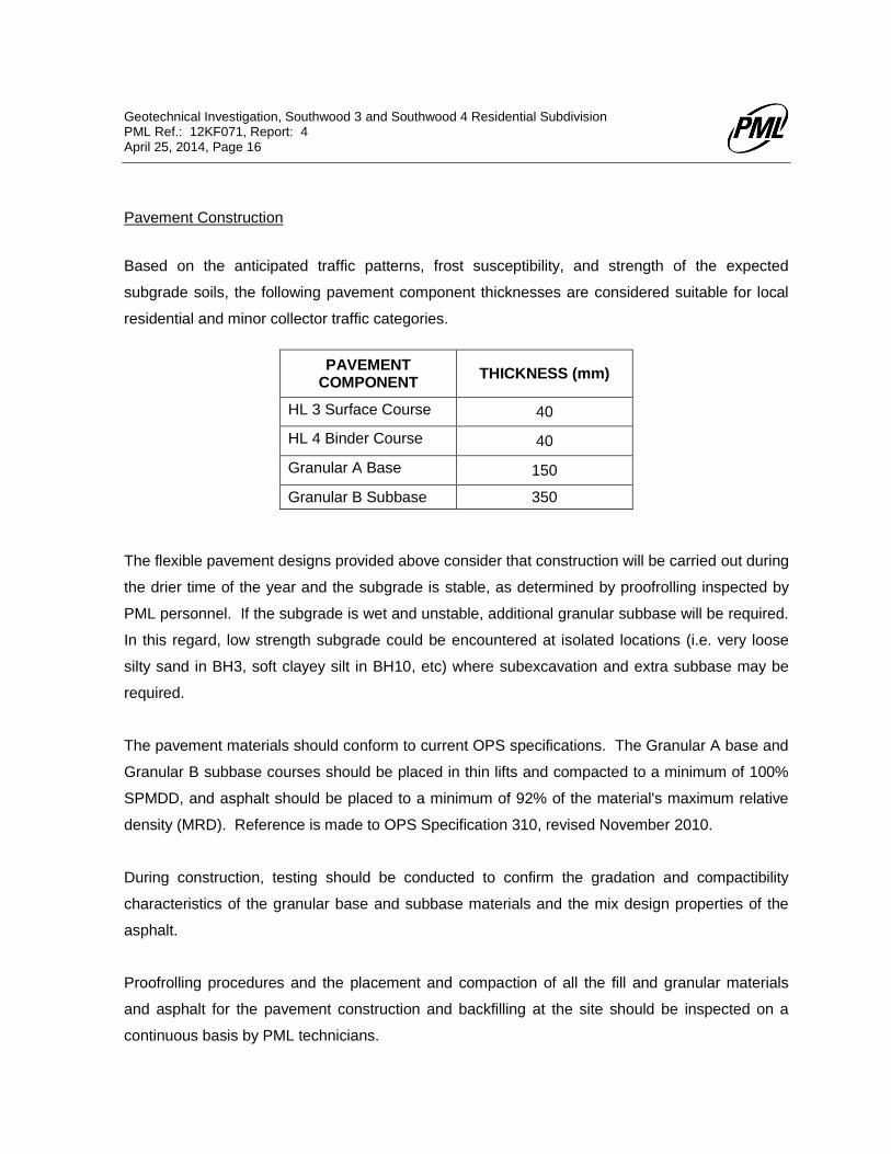
Pavement Construction
Based on the anticipated traffic patterns, frost susceptibility, and strength of the expected
subgrade soils, the following pavement component thicknesses are considered suitable for local
residential and minor collector traffic categories.
PAVEMENT COMPONENT
THICKNESS (mm)
HL 3 Surface Course 40
HL 4 Binder Course 40
Granular A Base 150
Granular B Subbase 350
The flexible pavement designs provided above consider that construction will be carried out during
the drier time of the year and the subgrade is stable, as determined by proofrolling inspected by
PML personnel. If the subgrade is wet and unstable, additional granular subbase will be required.
In this regard, low strength subgrade could be encountered at isolated locations (i.e. very loose
silty sand in BH3, soft clayey silt in BH10, etc) where subexcavation and extra subbase may be
required.
The pavement materials should conform to current OPS specifications. The Granular A base and
Granular B subbase courses should be placed in thin lifts and compacted to a minimum of 100%
SPMDD, and asphalt should be placed to a minimum of 92% of the material's maximum relative
density (MRD). Reference is made to OPS Specification 310, revised November 2010.
During construction, testing should be conducted to confirm the gradation and compactibility
characteristics of the granular base and subbase materials and the mix design properties of the
asphalt.
Proofrolling procedures and the placement and compaction of all the fill and granular materials
and asphalt for the pavement construction and backfilling at the site should be inspected on a
continuous basis by PML technicians.
Geotechnical Investigation, Southwood 3 and Southwood 4 Residential Subdivision PML Ref.: 12KF071, Report: 4 April 25, 2014, Page 17
Since relatively impermeable silty clay / clayey silt till material will be present at shallow depth
beneath the pavement structure in several areas, pavement subdrains should be provided to
prevent water accumulation on the pavement subgrade surface. The subgrade should be graded
so that water is directed to the catch basin structures or to the pavement edge. Subdrains should
be discharged in to the catch basins. The subdrains may consist of filter wrapped, 100 mm
diameter perforated plastic pipe, set within the subbase layer at the subgrade surface.
Storm Water Management Ponds and Ground Water Infiltration
A portion of land within the southern portion of the site has been set aside for storm water
management (SWM) ponds (BH11 and BH16 to BH19). According to WalterFedy project number
2011-0071-10 (Figures 10 and 11), the maximum depth of the Southwood 3 SWM pond is
expected to be approximately 5.5 m below existing grades (elevation 357). The side slopes of the
SWM pond are expected to be set at inclinations of between 3H:1V and 5H:1V. Details of the
proposed Southwood 4 SWM pond expansion were not provided, however, a maximum depth of
5.5 m is assumed. A temporary trench is to be constructed to connect the Southwood 3
residential subdivision to the storm pond until Southwood 4 is constructed (BH2, BH17, BH18).
The trench is expected to be set at a depth of about 4.0 m below existing grades.
Based on the findings of the boreholes, the subsurface soils in the SWM pond areas comprised
surficial topsoil over silty clay / clayey silt / clayey silt till to depths of 2.4 to 6.1 m (elevations 356.6
to 360.0) overlying a silt till deposit which extended to the borehole termination depths at all
locations. Shallow ground water was contacted between depths of 1.37 and 3.05 m below grade
within the shallow ground water monitoring wells (corresponding to elevations of between 358.20
and 361.83). Similar soil and ground water conditions were encountered along the trench; at the
northern portion (BH2), the silty clay extended to 4.6 m below grade (elevation 360.7) with shallow
ground water measured at a depth of 1.0 m (elevation 364.25).
Based on these findings, an infiltration type system will not be feasible and a retention type
system is indicated.
Geotechnical Investigation, Southwood 3 and Southwood 4 Residential Subdivision PML Ref.: 12KF071, Report: 4 April 25, 2014, Page 18
Any SWM ponds should be inspected by PML personnel during construction to verify the
presence of a suitable subgrade. In general, the slopes of the storm water management pond
and the storm water trench should be constructed at 3H:1V or shallower and be provided with
vegetation cover to minimize the potential for erosion and sloughing of the side slopes.
Soil infiltration rates were estimated for the major soil units from across the site from particle size
distribution charts. The major subsoils encountered throughout the SWM pond areas were
estimated to have a coefficient of permeability of less than 1 x 10⁻⁶
cm/s corresponding to a
steady-state infiltration rate of less than 0.005 mm/hr. Reference is made to the hydrogeological
site assessment (Report 3) for further details regarding the coefficient of permeability.
The majority of the on-site soils contain considerable amounts of fine grained soils (greater than
20% silt) and would not be feasible for source infiltration of roof leader water.
Geotechnical Investigation, Southwood 3 and Southwood 4 Residential Subdivision PML Ref.: 12KF071, Report: 4 April 25, 2014
Table 1, Page 1 of 4
TABLE 1
GROUND WATER ELEVATION MONITORING
Monitoring Well No.
Ground Surface
Elevation (m)
Screen Depth (mbgs)
Mid-Screen
Elevation (m) and (Depth) (mbgs)
Ground Water Elevation / Depth
Init
ial
16/0
1/2
013
02/0
5/2
013
20/0
6/2
013
18/0
7/2
013
19/0
8/2
013
24/1
0/2
013
05/1
1/2
013
04/1
2/2
013
10/0
1/2
014
30/0
1/2
014
21-2
8/0
2/2
014
25/0
3/2
014
1 363.75 5.3 ~ 6.8 357.65 <356.95 <356.95 358.25 358.55 358.65 358.74 358.59 358.62 358.80 358.56 358.55 358.42 358.15
6.1 -- -- 5.50 5.20 5.10 5.01 5.16 5.13 4.95 5.19 5.20 5.33 5.60
1A 363.95 1.5 ~ 3.0 361.75 <360.95 361.72 363.15 362.12 362.85 362.65 362.89 363.37 363.10 362.95 362.85 362.62 362.65
2.2 -- 2.23 0.80 1.83 1.10 1.30 1.06 0.58 0.85 1.00 1.10 1.33 1.30
2 365.30 10.7 ~ 12.2
353.90 <353.10 <353.10 <353.10 <353.10 <353.10 <353.10 <353.10 <353.10 353.30 <353.10 <353.10 353.24 353.12
11.4 -- -- -- -- -- -- -- -- 12.00 -- -- 12.06 12.18
2A 365.25 1.5 ~ 3.0 363.05 <362.25 362.56 364.43 364.37 364.10 363.75 363.70 364.45 364.30 364.08 364.11 364.05 364.25
2.2 -- 2.69 0.82 0.88 1.15 1.50 1.55 0.80 0.95 1.17 1.14 1.20 1.00
6 366.60 10.7 ~ 12.2
355.20 354.87 356.67 359.32 359.68 359.65 359.25 358.66 359.20 359.68 359.71 359.80 359.98 359.77
11.4 -- 9.93 7.28 6.92 6.95 7.35 7.94 7.40 6.92 6.89 6.80 6.62 6.83
6A 366.60 1.5 ~ 3.0 364.40 <363.60 364.73 365.70 365.63 365.40 365.00 365.59 365.86 365.55 365.47 365.35 365.37 365.48
2.2 -- 1.87 0.90 0.97 1.20 1.60 1.01 0.74 1.05 1.13 1.25 1.23 1.12
7 366.10 9.8 ~ 11.3 355.60 <354.80 <354.80 355.11 355.70 356.00 356.28 356.33 356.20 356.45 356.71 356.85 356.90 356.80
10.5 -- -- 10.99 10.40 10.10 9.82 9.77 9.90 9.65 9.39 9.25 9.20 9.30
7A 366.00 2.3 ~ 3.8 363.00 <362.20 <362.20 363.32 363.78 363.95 363.92 363.78 363.94 363.85 363.58 363.72 363.68 363.56
3.0 -- -- 2.68 2.22 2.05 2.08 2.22 2.06 2.15 2.42 2.28 2.32 2.44
8 365.20 5.4 ~ 6.9 359.10 359.05 <357.9 362.37 362.37 362.40 362.26 361.86 363.40 362.50 362.41 362.35 362.32 361.95
6.1 6.15 -- 2.83 2.83 2.80 2.94 3.34 1.80 2.70 2.79 2.85 2.88 3.25
Geotechnical Investigation, Southwood 3 and Southwood 4 Residential Subdivision PML Ref.: 12KF071, Report: 4 April 25, 2014
Table 1, Page 2 of 4
TABLE 1
GROUND WATER ELEVATION MONITORING
Monitoring Well No.
Ground Surface
Elevation (m)
Screen Depth (mbgs)
Mid-Screen
Elevation (m) and (Depth) (mbgs)
Ground Water Elevation / Depth
Init
ial
16/0
1/2
013
02/0
5/2
013
20/0
6/2
013
18/0
7/2
013
19/0
8/2
013
24/1
0/2
013
05/1
1/2
013
04/1
2/2
013
10/0
1/2
014
30/0
1/2
014
21-2
8/0
2/2
014
25/0
3/2
014
8A 365.25 1.5 ~ 3.0 363.05 363.00 363.01 364.24 364.23 364.05 363.57 363.81 364.40 364.15 364.09 3.64.09 363.95 364.11
2.2 2.25 2.24 1.01 1.02 1.20 1.68 1.44 0.85 1.10 1.16 1.16 1.30 1.14
9 364.0 10.7 ~ 12.2
352.60 354.35 352.15 <351.80 <351.80 352.40 352.37 352.45 352.75 353.00 <351.80 353.22 352.85 352.42
11.4 9.65 11.85 -- -- 11.60 11.63 11.55 11.25 11.00 -- 10.78 11.15 11.58
9A 363.95 1.5 ~ 3.0 361.75 361.72 362.20 363.20 362.88 362.45 362.80 363.30 363.40 363.10 363.00 362.93 362.85 363.27
2.2 2.23 1.75 0.75 1.07 1.50 1.15 0.65 0.55 0.85 0.95 1.02 1.10 0.68
11 363.15 10.7 ~ 12.3
351.75 <350.85 <350.85 350.93 350.97 350.95 351.01 351.01 351.00 <350.85 350.91 <350.85 350.90 350.88
11.4 -- -- 12.22 12.18 12.20 12.14 12.14 12.15 -- 12.24 -- 12.25 12.27
11A 363.20 1.5 ~ 3.0 361.00 <360.20 361.40 362.38 362.22 362.00 361.55 361.52 362.55 362.25 362.13 361.92 361.82 361.83
2.2 -- 1.80 0.82 0.98 1.20 1.65 1.68 0.65 0.95 1.07 1.28 1.38 1.37
12 362.32 9.2 ~10.7 352.42 <351.40 -- -- -- -- -- -- 356.03 356.26 355.94 355.88 355.89 355.64
9.9 -- -- -- -- -- -- -- 6.29 6.06 6.38 6.44 6.43 6.68
12A 362.32 1.5 ~ 3.0 360.12 <359.32 -- -- -- -- -- -- <359.32 359.52 359.83 360.15 360.50 360.60
2.2 -- -- -- -- -- -- -- -- 2.80 2.49 2.17 1.82 1.72
13 365.13 1.5 ~ 3.0 362.93 <362.13 -- -- -- -- -- -- 364.03 363.68 363.67 363.68 363.54 363.76
2.2 -- -- -- -- -- -- -- 1.1 1.45 1.46 1.45 1.59 1.37
14 365.25 4.6 ~ 6.1 359.45 360.03 -- -- -- -- -- -- 364.17 363.88 363.79 363.73 363.56 363.99
5.8 5.22 -- -- -- -- -- -- 1.08 1.37 1.46 1.52 1.69 1.26
Geotechnical Investigation, Southwood 3 and Southwood 4 Residential Subdivision PML Ref.: 12KF071, Report: 4 April 25, 2014
Table 1, Page 3 of 4
TABLE 1
GROUND WATER ELEVATION MONITORING
Monitoring Well No.
Ground Surface
Elevation (m)
Screen Depth (mbgs)
Mid-Screen
Elevation (m) and (Depth) (mbgs)
Ground Water Elevation / Depth
Init
ial
16/0
1/2
013
02/0
5/2
013
20/0
6/2
013
18/0
7/2
013
19/0
8/2
013
24/1
0/2
013
05/1
1/2
013
04/1
2/2
013
10/0
1/2
014
30/0
1/2
014
21-2
8/0
2/2
014
25/0
3/2
014
14A 365.20 1.5 ~ 3.0 363.00 362.40 -- -- -- -- -- -- 364.67 364.25 364.08 364.12 363.95 364.35
2.2 2.80 -- -- -- -- -- -- 0.53 0.95 1.12 1.08 1.25 0.85
15 364.25 12.2 ~ 13.7
351.25 -- -- -- -- -- -- -- -- -- -- 350.60 <350.55
13.0 -- -- -- -- -- -- -- -- -- -- 13.65 --
15A 364.25 1.5 ~ 3.0 362.05 -- -- -- -- -- -- -- -- -- -- 361.48 362.70
2.2 -- -- -- -- -- -- -- -- -- -- 2.77 1.55
16 361.20 10.7 ~ 12.2
349.8 -- -- -- -- -- -- -- -- -- -- 349.10 349.09
11.4 -- -- -- -- -- -- -- -- -- -- 12.10 12.11
16A 361.20 1.5 ~ 3.0 359.0 -- -- -- -- -- -- -- -- -- -- 358.20 358.20
2.2 -- -- -- -- -- -- -- -- -- -- 3.00 3.00
19 362.40 10.7 ~ 12.2
351.0 -- -- -- -- -- -- -- -- -- -- 353.95 354.42
11.4 -- -- -- -- -- -- -- -- -- -- 8.45 7.98
19A 362.35 1.5 ~ 3.0 360.15 -- -- -- -- -- -- -- -- -- -- 359.27 359.30
2.2 -- -- -- -- -- -- -- -- -- -- 3.08 3.05
20 360.00 6.1 ~ 7.6 353.1 -- -- -- -- -- -- -- -- -- -- <352.4 <352.4
6.9 -- -- -- -- -- -- -- -- -- -- -- --
20A 359.95 1.5 ~ 3.0 357.75 -- -- -- -- -- -- -- -- -- -- 358.26 359.20
2.2 -- -- -- -- -- -- -- -- -- -- 1.69 0.75
Geotechnical Investigation, Southwood 3 and Southwood 4 Residential Subdivision PML Ref.: 12KF071, Report: 4 April 25, 2014
Table 1, Page 4 of 4
TABLE 1
GROUND WATER ELEVATION MONITORING
Monitoring Well No.
Ground Surface
Elevation (m)
Screen Depth (mbgs)
Mid-Screen
Elevation (m) and (Depth) (mbgs)
Ground Water Elevation / Depth
Init
ial
16/0
1/2
013
02/0
5/2
013
20/0
6/2
013
18/0
7/2
013
19/0
8/2
013
24/1
0/2
013
05/1
1/2
013
04/1
2/2
013
10/0
1/2
014
30/0
1/2
014
21-2
8/0
2/2
014
25/0
3/2
014
22 359.55 6.1 ~ 7.6 352.65 -- -- -- -- -- -- -- -- -- -- -- 357.30 358.25
6.9 -- -- -- -- -- -- -- -- -- -- -- 2.25 1.30
22A 359.50 1.5 ~ 3.0 357.3 -- -- -- -- -- -- -- -- -- -- -- 357.53 358.42
2.2 -- -- -- -- -- -- -- -- -- -- -- 1.97 1.08
Note: m = geodetic elevation, and mbgs = metre below ground surface (values in Italic)
CO
AR
SE
ME
DIU
M
PM
L R
EF
.
SA
MP
LE N
O.:
PA
RT
ICLE
SIZ
E D
IST
RIB
UT
ION
CH
AR
T
SIL
T
FIN
EC
OA
RS
E
SIL
T
CO
AR
SE
FIN
E
UN
IFIE
D
RE
MA
RK
SB
ore
hole
2,
Sam
ple
SS
4,
Depth
2.3
0 -
2.7
5 m
SIL
TY
CLA
Y,
TR
AC
E S
AN
D,
TR
AC
E G
RA
VE
L
M.I.
T.
U.S
. B
UR
EA
U
CO
AR
SE
SA
ND
CL
AY
CL
AY
GR
AV
EL
GR
AV
EL
CO
BB
LE
S
12K
F071
SIL
T &
CL
AY
SA
ND
VE
RY
FIN
E
FIN
E
SA
ND
ME
DIU
M
ME
DIU
M
1
33315
FIG
UR
E N
O.
CO
B
BL
ES
FIN
EM
ED
IUM
GR
AV
EL
0102030405060708090100 0.
001
0.01
00.
100
1.00
010
.000
100.
000
CUMULATIVE PERCENT PASSING
GR
AIN
SIZ
E IN
MIL
LIM
ET
ER
S
U.S
. S
TA
ND
AR
D S
IEV
E S
IZE
SH
YD
RO
ME
TE
R2
70
2
00
14
0
10
0
80
60
40
20
1
6 1
4
1
0
8
4
1/4
"
3/8
"
1/2
"
3
/4"
1
"
1
-1/2
"
2"
3
"
0.0
01
0
.00
5
0
.01
0.0
5
0
.1
0.5
1
.0
5
.0
1
0 .0
5
0 .
0
1
00
.0
CO
AR
SE
ME
DIU
M
PM
L R
EF
.
SA
MP
LE N
O.:
PA
RT
ICLE
SIZ
E D
IST
RIB
UT
ION
CH
AR
T
SIL
T
FIN
EC
OA
RS
E
SIL
T
CO
AR
SE
FIN
E
UN
IFIE
D
RE
MA
RK
SB
ore
hole
5,
Sam
ple
SS
5,
Depth
3.0
- 3
.45 m
SIL
TY
CLA
Y,
SO
ME
SA
ND
, T
RA
CE
GR
AV
EL
M.I.
T.
U.S
. B
UR
EA
U
CO
AR
SE
SA
ND
CL
AY
CL
AY
GR
AV
EL
GR
AV
EL
CO
BB
LE
S
12K
F071
SIL
T &
CL
AY
SA
ND
VE
RY
FIN
E
FIN
E
SA
ND
ME
DIU
M
ME
DIU
M
2
33316
FIG
UR
E N
O.
CO
B
BL
ES
FIN
EM
ED
IUM
GR
AV
EL
0102030405060708090100 0.
001
0.01
00.
100
1.00
010
.000
100.
000
CUMULATIVE PERCENT PASSING
GR
AIN
SIZ
E IN
MIL
LIM
ET
ER
S
U.S
. S
TA
ND
AR
D S
IEV
E S
IZE
SH
YD
RO
ME
TE
R2
70
2
00
14
0
10
0
80
60
40
20
1
6 1
4
1
0
8
4
1/4
"
3/8
"
1/2
"
3
/4"
1
"
1
-1/2
"
2"
3
"
0.0
01
0
.00
5
0
.01
0.0
5
0
.1
0.5
1
.0
5
.0
1
0 .0
5
0 .
0
1
00
.0
CO
AR
SE
ME
DIU
M
PM
L R
EF
.
SA
MP
LE N
O.:
PA
RT
ICLE
SIZ
E D
IST
RIB
UT
ION
CH
AR
T
SIL
T
FIN
EC
OA
RS
E
SIL
T
CO
AR
SE
FIN
E
UN
IFIE
D
RE
MA
RK
SB
ore
hole
6,
Sam
ple
SS
10,
Depth
10.7
0 -
11.1
5 m
SIL
T T
ILL,
SO
ME
GR
AV
EL,
TR
AC
E S
AN
D
M.I.
T.
U.S
. B
UR
EA
U
CO
AR
SE
SA
ND
CL
AY
CL
AY
GR
AV
EL
GR
AV
EL
CO
BB
LE
S
12K
F071
SIL
T &
CL
AY
SA
ND
VE
RY
FIN
E
FIN
E
SA
ND
ME
DIU
M
ME
DIU
M
3
33317
FIG
UR
E N
O.
CO
B
BL
ES
FIN
EM
ED
IUM
GR
AV
EL
0102030405060708090100 0.
001
0.01
00.
100
1.00
010
.000
100.
000
CUMULATIVE PERCENT PASSING
GR
AIN
SIZ
E IN
MIL
LIM
ET
ER
S
U.S
. S
TA
ND
AR
D S
IEV
E S
IZE
SH
YD
RO
ME
TE
R2
70
2
00
14
0
10
0
80
60
40
20
1
6 1
4
1
0
8
4
1/4
"
3/8
"
1/2
"
3
/4"
1
"
1
-1/2
"
2"
3
"
0.0
01
0
.00
5
0
.01
0.0
5
0
.1
0.5
1
.0
5
.0
1
0 .0
5
0 .
0
1
00
.0

CO
AR
SE
ME
DIU
M
PM
L R
EF
.
SA
MP
LE N
O.:
PA
RT
ICLE
SIZ
E D
IST
RIB
UT
ION
CH
AR
T
SIL
T
FIN
EC
OA
RS
E
SIL
T
CO
AR
SE
FIN
E
UN
IFIE
D
RE
MA
RK
SB
ore
hole
10,
Sam
ple
SS
4.
Depth
2.3
0 -
2.7
5 m
CLA
YE
Y S
ILT
, T
RA
CE
SA
ND
, T
RA
CE
GR
AV
EL
M.I.
T.
U.S
. B
UR
EA
U
CO
AR
SE
SA
ND
CL
AY
CL
AY
GR
AV
EL
GR
AV
EL
CO
BB
LE
S
12K
F071
SIL
T &
CL
AY
SA
ND
VE
RY
FIN
E
FIN
E
SA
ND
ME
DIU
M
ME
DIU
M
4
33318
FIG
UR
E N
O.
CO
B
BL
ES
FIN
EM
ED
IUM
GR
AV
EL
0102030405060708090100 0.
001
0.01
00.
100
1.00
010
.000
100.
000
CUMULATIVE PERCENT PASSING
GR
AIN
SIZ
E IN
MIL
LIM
ET
ER
S
U.S
. S
TA
ND
AR
D S
IEV
E S
IZE
SH
YD
RO
ME
TE
R2
70
2
00
14
0
10
0
80
60
40
20
1
6 1
4
1
0
8
4
1/4
"
3/8
"
1/2
"
3
/4"
1
"
1
-1/2
"
2"
3
"
0.0
01
0
.00
5
0
.01
0.0
5
0
.1
0.5
1
.0
5
.0
1
0 .0
5
0 .
0
1
00
.0
CO
AR
SE
ME
DIU
M
ME
DIU
M
ME
DIU
M
5
33319
FIG
UR
E N
O.
CO
B
BL
ES
FIN
EM
ED
IUM
GR
AV
EL
GR
AV
EL
GR
AV
EL
CO
BB
LE
S
12K
F071
SIL
T &
CL
AY
SA
ND
VE
RY
FIN
E
FIN
E
SA
ND
UN
IFIE
D
RE
MA
RK
SB
ore
hole
11,
Sam
ple
SS
7,
Depth
6.1
0 -
6.5
5 m
SA
ND
Y S
ILT
TIL
L,
TR
AC
E G
RA
VE
L
M.I.
T.
U.S
. B
UR
EA
U
CO
AR
SE
SA
ND
CL
AY
CL
AY
PM
L R
EF
.
SA
MP
LE N
O.:
PA
RT
ICLE
SIZ
E D
IST
RIB
UT
ION
CH
AR
T
SIL
T
FIN
EC
OA
RS
E
SIL
T
CO
AR
SE
FIN
E
0102030405060708090100 0.
001
0.01
00.
100
1.00
010
.000
100.
000
CUMULATIVE PERCENT PASSING
GR
AIN
SIZ
E IN
MIL
LIM
ET
ER
S
U.S
. S
TA
ND
AR
D S
IEV
E S
IZE
SH
YD
RO
ME
TE
R2
70
2
00
14
0
10
0
80
60
40
20
1
6 1
4
1
0
8
4
1/4
"
3/8
"
1/2
"
3
/4"
1
"
1
-1/2
"
2"
3
"
0.0
01
0
.00
5
0
.01
0.0
5
0
.1
0.5
1
.0
5
.0
1
0 .0
5
0 .
0
1
00
.0
CO
AR
SE
ME
DIU
M
PM
L R
EF
.
SA
MP
LE N
O.:
PA
RT
ICLE
SIZ
E D
IST
RIB
UT
ION
CH
AR
T
SIL
T
FIN
EC
OA
RS
E
SIL
T
CO
AR
SE
FIN
E
UN
IFIE
D
RE
MA
RK
SB
ore
hole
12,
Sam
ple
SS
7,
Depth
7.6
0 t
o 8
.10 m
CLA
YE
Y S
ILT
TIL
L,
SO
ME
SA
ND
, T
RA
CE
GR
AV
EL
M.I.
T.
U.S
. B
UR
EA
U
CO
AR
SE
SA
ND
CL
AY
CL
AY
GR
AV
EL
GR
AV
EL
CO
BB
LE
S
12K
F071
SIL
T &
CL
AY
SA
ND
VE
RY
FIN
E
FIN
E
SA
ND
ME
DIU
M
ME
DIU
M
6 35348
FIG
UR
E N
O.
CO
B
BL
ES
FIN
EM
ED
IUM
GR
AV
EL
0102030405060708090100 0.
001
0.01
00.
100
1.00
010
.000
100.
000
CUMULATIVE PERCENT PASSING
GR
AIN
SIZ
E IN
MIL
LIM
ET
ER
S
U.S
. S
TA
ND
AR
D S
IEV
E S
IZE
SH
YD
RO
ME
TE
R2
70
2
00
14
0
10
0
80
60
40
20
1
6 1
4
1
0
8
4
1/4
"
3/8
"
1/2
"
3
/4"
1
"
1
-1/2
"
2"
3
"
0.0
01
0
.00
5
0
.01
0.0
5
0
.1
0.5
1
.0
5
.0
1
0 .0
5
0 .
0
1
00
.0
CO
AR
SE
ME
DIU
M
ME
DIU
M
ME
DIU
M
7 35349
FIG
UR
E N
O.
CO
B
BL
ES
FIN
EM
ED
IUM
GR
AV
EL
GR
AV
EL
GR
AV
EL
CO
BB
LE
S
12K
F071
SIL
T &
CL
AY
SA
ND
VE
RY
FIN
E
FIN
E
SA
ND
UN
IFIE
D
RE
MA
RK
SB
ore
hole
13,
Sam
ple
SS
3,
Depth
2.3
0 t
o 2
.70 m
SIL
TY
CLA
Y,
TR
AC
E S
AN
D,
TR
AC
E G
RA
VE
L
M.I.
T.
U.S
. B
UR
EA
U
CO
AR
SE
SA
ND
CL
AY
CL
AY
PM
L R
EF
.
SA
MP
LE N
O.:
PA
RT
ICLE
SIZ
E D
IST
RIB
UT
ION
CH
AR
T
SIL
T
FIN
EC
OA
RS
E
SIL
T
CO
AR
SE
FIN
E
0102030405060708090100 0.
001
0.01
00.
100
1.00
010
.000
100.
000
CUMULATIVE PERCENT PASSING
GR
AIN
SIZ
E IN
MIL
LIM
ET
ER
S
U.S
. S
TA
ND
AR
D S
IEV
E S
IZE
SH
YD
RO
ME
TE
R2
70
2
00
14
0
10
0
80
60
40
20
1
6 1
4
1
0
8
4
1/4
"
3/8
"
1/2
"
3
/4"
1
"
1
-1/2
"
2"
3
"
0.0
01
0
.00
5
0
.01
0.0
5
0
.1
0.5
1
.0
5
.0
1
0 .0
5
0 .
0
1
00
.0
CO
AR
SE
ME
DIU
M
PM
L R
EF
.
PA
RT
ICLE
SIZ
E D
IST
RIB
UT
ION
CH
AR
T
SIL
T
FIN
EC
OA
RS
E
SIL
T
CO
AR
SE
FIN
E
UN
IFIE
D
RE
MA
RK
SB
ore
hole
15,
Sam
ple
SS
3,
Depth
2.3
0 -
2.7
5 m
SIL
TY
CLA
Y,
SO
ME
SA
ND
, T
RA
CE
GR
AV
EL
M.I.
T.
U.S
. B
UR
EA
U
CO
AR
SE
SA
ND
CL
AY
CL
AY
GR
AV
EL
GR
AV
EL
CO
BB
LE
S
12K
F071
SIL
T &
CL
AY
SA
ND
VE
RY
FIN
E
FIN
E
SA
ND
ME
DIU
M
ME
DIU
M
8F
IGU
RE
NO
.
CO
B
BL
ES
FIN
EM
ED
IUM
GR
AV
EL
0102030405060708090100 0.
001
0.01
00.
100
1.00
010
.000
100.
000
CUMULATIVE PERCENT PASSING
GR
AIN
SIZ
E IN
MIL
LIM
ET
ER
S
U.S
. S
TA
ND
AR
D S
IEV
E S
IZE
SH
YD
RO
ME
TE
R2
70
2
00
14
0
10
0
80
60
40
20
1
6 1
4
1
0
8
4
1/4
"
3/8
"
1/2
"
3
/4"
1
"
1
-1/2
"
2"
3
"
0.0
01
0
.00
5
0
.01
0.0
5
0
.1
0.5
1
.0
5
.0
1
0 .0
5
0 .
0
1
00
.0
CO
AR
SE
ME
DIU
M
PM
L R
EF
.
PA
RT
ICLE
SIZ
E D
IST
RIB
UT
ION
CH
AR
T
SIL
T
FIN
EC
OA
RS
E
SIL
T
CO
AR
SE
FIN
E
UN
IFIE
D
RE
MA
RK
SB
ore
hole
19,
Sam
ple
SS
10,
Depth
12.2
0 -
12.6
5 m
SA
ND
Y S
ILT
TIL
L,
TR
AC
E C
LA
Y,
TR
AC
E G
RA
VE
L
M.I.
T.
U.S
. B
UR
EA
U
CO
AR
SE
SA
ND
CL
AY
CL
AY
GR
AV
EL
GR
AV
EL
CO
BB
LE
S
12K
F071
SIL
T &
CL
AY
SA
ND
VE
RY
FIN
E
FIN
E
SA
ND
ME
DIU
M
ME
DIU
M
9F
IGU
RE
NO
.
CO
B
BL
ES
FIN
EM
ED
IUM
GR
AV
EL
0102030405060708090100 0.
001
0.01
00.
100
1.00
010
.000
100.
000
CUMULATIVE PERCENT PASSING
GR
AIN
SIZ
E IN
MIL
LIM
ET
ER
S
U.S
. S
TA
ND
AR
D S
IEV
E S
IZE
SH
YD
RO
ME
TE
R2
70
2
00
14
0
10
0
80
60
40
20
1
6 1
4
1
0
8
4
1/4
"
3/8
"
1/2
"
3
/4"
1
"
1
-1/2
"
2"
3
"
0.0
01
0
.00
5
0
.01
0.0
5
0
.1
0.5
1
.0
5
.0
1
0 .0
5
0 .
0
1
00
.0
CO
AR
SE
ME
DIU
M
PM
L R
EF
.
PA
RT
ICLE
SIZ
E D
IST
RIB
UT
ION
CH
AR
T
SIL
T
FIN
EC
OA
RS
E
SIL
T
CO
AR
SE
FIN
E
UN
IFIE
D
RE
MA
RK
SB
ore
hole
20,
Sam
ple
SS
7,
Depth
6.1
0 -
6.5
5 m
SA
ND
Y S
ILT
TIL
L,
TR
AC
E C
LA
Y,
TR
AC
E G
RA
VE
L
M.I.
T.
U.S
. B
UR
EA
U
CO
AR
SE
SA
ND
CL
AY
CL
AY
GR
AV
EL
GR
AV
EL
CO
BB
LE
S
12K
F071
SIL
T &
CL
AY
SA
ND
VE
RY
FIN
E
FIN
E
SA
ND
ME
DIU
M
ME
DIU
M
10
FIG
UR
E N
O.
CO
B
BL
ES
FIN
EM
ED
IUM
GR
AV
EL
0102030405060708090100 0.
001
0.01
00.
100
1.00
010
.000
100.
000
CUMULATIVE PERCENT PASSING
GR
AIN
SIZ
E IN
MIL
LIM
ET
ER
S
U.S
. S
TA
ND
AR
D S
IEV
E S
IZE
SH
YD
RO
ME
TE
R2
70
2
00
14
0
10
0
80
60
40
20
1
6 1
4
1
0
8
4
1/4
"
3/8
"
1/2
"
3
/4"
1
"
1
-1/2
"
2"
3
"
0.0
01
0
.00
5
0
.01
0.0
5
0
.1
0.5
1
.0
5
.0
1
0 .0
5
0 .
0
1
00
.0
CO
AR
SE
ME
DIU
M
PM
L R
EF
.
PA
RT
ICLE
SIZ
E D
IST
RIB
UT
ION
CH
AR
T
SIL
T
FIN
EC
OA
RS
E
SIL
T
CO
AR
SE
FIN
E
UN
IFIE
D
RE
MA
RK
SB
ore
hole
22,
Sam
ple
SS
7,
Depth
6.1
0 -
6.5
5 m
SA
ND
Y S
ILT
TIL
L,
TR
AC
E C
LA
Y,
TR
AC
E G
RA
VE
L
M.I.
T.
U.S
. B
UR
EA
U
CO
AR
SE
SA
ND
CL
AY
CL
AY
GR
AV
EL
GR
AV
EL
CO
BB
LE
S
12K
F071
SIL
T &
CL
AY
SA
ND
VE
RY
FIN
E
FIN
E
SA
ND
ME
DIU
M
ME
DIU
M
11
FIG
UR
E N
O.
CO
B
BL
ES
FIN
EM
ED
IUM
GR
AV
EL
0102030405060708090100 0.
001
0.01
00.
100
1.00
010
.000
100.
000
CUMULATIVE PERCENT PASSING
GR
AIN
SIZ
E IN
MIL
LIM
ET
ER
S
U.S
. S
TA
ND
AR
D S
IEV
E S
IZE
SH
YD
RO
ME
TE
R2
70
2
00
14
0
10
0
80
60
40
20
1
6 1
4
1
0
8
4
1/4
"
3/8
"
1/2
"
3
/4"
1
"
1
-1/2
"
2"
3
"
0.0
01
0
.00
5
0
.01
0.0
5
0
.1
0.5
1
.0
5
.0
1
0 .0
5
0 .
0
1
00
.0
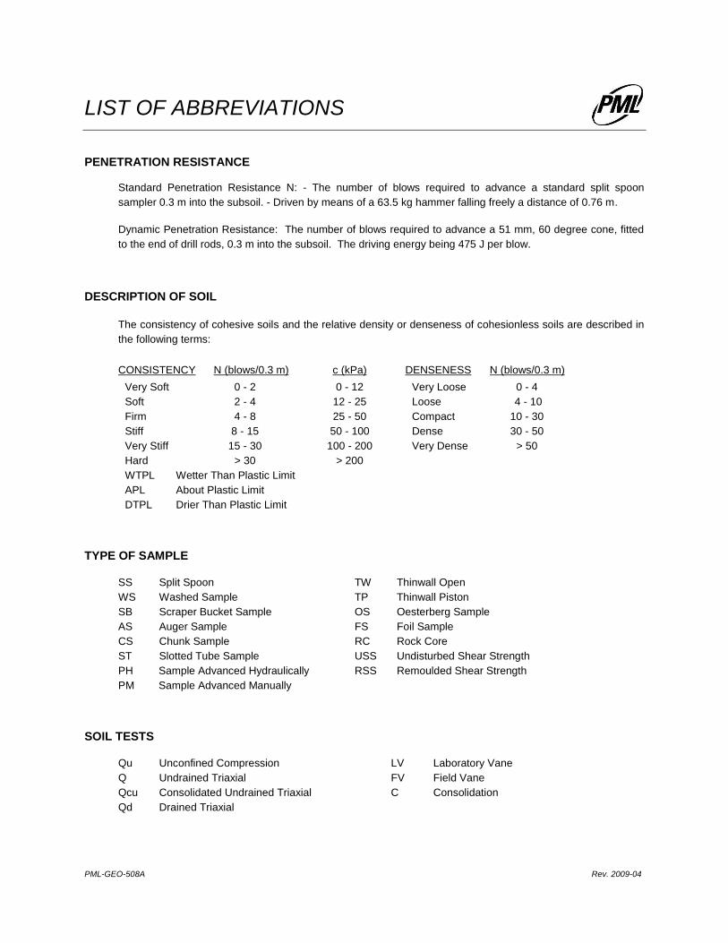
LIST OF ABBREVIATIONS
PENETRATION RESISTANCE
Standard Penetration Resistance N: - The number of blows required to advance a standard split spoon
sampler 0.3 m into the subsoil. - Driven by means of a 63.5 kg hammer falling freely a distance of 0.76 m.
Dynamic Penetration Resistance: The number of blows required to advance a 51 mm, 60 degree cone, fitted
to the end of drill rods, 0.3 m into the subsoil. The driving energy being 475 J per blow.
DESCRIPTION OF SOIL
The consistency of cohesive soils and the relative density or denseness of cohesionless soils are described in
the following terms:
CONSISTENCY N (blows/0.3 m) c (kPa) DENSENESS N (blows/0.3 m)
Very Soft 0 - 2 0 - 12 Very Loose 0 - 4
Soft 2 - 4 12 - 25 Loose 4 - 10
Firm 4 - 8 25 - 50 Compact 10 - 30
Stiff 8 - 15 50 - 100 Dense 30 - 50
Very Stiff 15 - 30 100 - 200 Very Dense > 50
Hard > 30 > 200
WTPL Wetter Than Plastic Limit
APL About Plastic Limit
DTPL Drier Than Plastic Limit
TYPE OF SAMPLE
SS Split Spoon TW Thinwall Open
WS Washed Sample TP Thinwall Piston
SB Scraper Bucket Sample OS Oesterberg Sample
AS Auger Sample FS Foil Sample
CS Chunk Sample RC Rock Core
ST Slotted Tube Sample USS Undisturbed Shear Strength
PH Sample Advanced Hydraulically RSS Remoulded Shear Strength
PM Sample Advanced Manually
SOIL TESTS
Qu Unconfined Compression LV Laboratory Vane
Q Undrained Triaxial FV Field Vane
Qcu Consolidated Undrained Triaxial C Consolidation
Qd Drained Triaxial PML-GEO-508A Rev. 2009-04
1
2
3
4
5
6
7
8
SS
SS
SS
SS
SS
SS
SS
SS
3
9
23
20
26
18
25
77/250 mm
Stick up withJ-Plug
50 mm PlasticRiser
Bentonite Seal
Filter Sand
50 mm SlottedScreen
Water Levels:Date Depth(m) Elev.10/01/2013 Dry16/01/2013 Dry02/05/2013 5.5 358.25
0.23
0.50 363.25
0.95 362.80
3.0360.8
4.5359.3
7.0
7.3356.5
TOPSOIL: Dark brown clayey silt, trace,gravel, rootlets, moist to wetSILTY SAND: Very loose brown silty sand,trace clay, moist to wetCLAYEY SILT TILL: Firm brown and greymottled clayey silt, trace sand, APLbecoming very stiff, brown, trace gravel,DTPL
becoming grey, occasional silt seams
no seams
SILT TILL: Very dense grey silt, somegravel, dampBOREHOLE TERMINATED AT 7.3 m
(kPa)
kN/m3
UN
IT W
EIG
HT
LE
GE
ND
LIQUID LIMIT
NU
MB
ER
CHECKED BY
GROUND ELEVATION
PLASTIC LIMIT
South Parkwood Boulevard, Elmira, Ontario
WL
LOCATION
Southwood 3 Residential Subdivision
W
D. Brice
363.75
kh
BORING DATE:
REMOLDED FIELD VANEWATER LEVEL OBSERVED DURING /UPON COMPLETION OF DRILLING
POCKET PENETROMETER
POCKET TORVANE
LAB SHEAR TEST
12KF071
UNDISTURBED FIELD VANE
WATER LEVEL MEASURED INMONITORING WELL
PML REF.:
BL
OW
S/0
.3m
N -
VA
LU
ES
LOG OF BOREHOLE NO. 1
10 20 30
NU
MB
ER
SOIL PROFILE
20 40 60 80
TECHNICIAN
DESCRIPTIONDEPTH
in
METRES
NOTES:
M. Molodecki
PROJECT
GROUND WATER
OBSERVATIONS
AND REMARKS
LE
GE
ND
SAMPLES
TY
PE WP
WATER CONTENT
50 100 150 200
0.0
363
362
361
360
359
358
357
10/01/2013 ENGINEER
1.0
2.0
3.0
4.0
5.0
6.0
7.0
8.0
9.0
10.0
11.0
12.0
13.0
14.0
15.0
16.0
17.0
BLOWS/0.3M
BORING METHOD
WATER CONTENT %363.75
W
WL
Continuous Flight Hollow Stem Augers
GROUND ELEVATION
TY
PE
SHEAR STRENGTH Cu
DYNAMIC CONE PENETRATION
STANDARD PENETRATION TEST
BL
OW
S/0
.3m
N -
VA
LU
ES
EL
EV
AT
ION
SC
AL
E
WP
LOG OF BOREHOLE REV. 08/2012 12KF071 BOREHOLE LOGS.GPJ PETOMAC.GDT 2013 06 10
>>

Stick up withJ-Plug
50 mm PlasticRiserFilter Sand
50 mm SlottedScreen
Water Levels:Date Depth(m) Elev.10/01/2013 Dry16/01/2013 1.33 362.6202/05/2013 0.80 363.15
3.0361.0
Refer to Log of Borehole 1 for stratigraphy
BOREHOLE TERMINATED AT 3.0 m
(kPa)
kN/m3
UN
IT W
EIG
HT
LE
GE
ND
LIQUID LIMIT
NU
MB
ER
CHECKED BY
GROUND ELEVATION
PLASTIC LIMIT
South Parkwood Boulevard, Elmira, Ontario
WL
LOCATION
Southwood 3 Residential Subdivision
W
D. Brice
363.95
kh
BORING DATE:
REMOLDED FIELD VANEWATER LEVEL OBSERVED DURING /UPON COMPLETION OF DRILLING
POCKET PENETROMETER
POCKET TORVANE
LAB SHEAR TEST
12KF071
UNDISTURBED FIELD VANE
WATER LEVEL MEASURED INMONITORING WELL
Shallow well adjacent to primary borehole
PML REF.:
BL
OW
S/0
.3m
N -
VA
LU
ES
LOG OF BOREHOLE NO. 1A
10 20 30
NU
MB
ER
SOIL PROFILE
20 40 60 80
TECHNICIAN
DESCRIPTIONDEPTH
in
METRES
NOTES:
M. Molodecki
PROJECT
GROUND WATER
OBSERVATIONS
AND REMARKS
LE
GE
ND
SAMPLES
TY
PE WP
WATER CONTENT
50 100 150 200
0.0
363
362
361
10/01/2013 ENGINEER
1.0
2.0
3.0
4.0
5.0
6.0
7.0
8.0
9.0
10.0
11.0
12.0
13.0
14.0
15.0
16.0
17.0
BLOWS/0.3M
BORING METHOD
WATER CONTENT %363.95
W
WL
Continuous Flight Hollow Stem Augers
GROUND ELEVATION
TY
PE
SHEAR STRENGTH Cu
DYNAMIC CONE PENETRATION
STANDARD PENETRATION TEST
BL
OW
S/0
.3m
N -
VA
LU
ES
EL
EV
AT
ION
SC
AL
E
WP
LOG OF BOREHOLE REV. 08/2012 12KF071 BOREHOLE LOGS.GPJ PETOMAC.GDT 2013 06 10
1
2
3
4
5
6
7
8
9
10
11
SS
SS
SS
SS
SS
SS
SS
SS
SS
SS
SS
3
8
13
21
16
80
70
93/225 mm
84/225 mm
75
89
Stick up withJ-Plug
50 mm PlasticRiser
Bentonite Seal
Filter Sand
50 mm SlottedScreen
Water Levels:Date Depth(m) Elev.09/01/2013 Dry16/01/2013 Dry02/05/2013 Dry
0.250.40
364.90
2.3363.0
4.6360.7
6.2359.1
7.6357.7
9.1356.2
10.7354.6
12.8352.5
TOPSOIL: Dark brown clayey silt, tracegravel, rootlets, APLSILTY SAND: Very loose brown silty sand,moist to wetSILTY CLAY: Firm grey and brown mottledsilty clay, trace sand, APL, occasionalmoist to wet sand seams
becoming brown, trace gravel, no seams,DTPL
SILT TILL: Very dense grey silt, somesand, trace gravel, damp
CLAYEY SILT TILL: Hard grey clayey silt,trace gravel, DTPL
SILT TILL: Very dense grey silt, somegravel, trace sand, damp
occasional sand seams
no seams
BOREHOLE TERMINATED AT 12.8 m
(kPa)
kN/m3
UN
IT W
EIG
HT
LE
GE
ND
LIQUID LIMIT
NU
MB
ER
CHECKED BY
GROUND ELEVATION
PLASTIC LIMIT
South Parkwood Boulevard, Elmira, Ontario
WL
LOCATION
Southwood 3 Residential Subdivision
W
D. Brice
365.30
kh
BORING DATE:
REMOLDED FIELD VANEWATER LEVEL OBSERVED DURING /UPON COMPLETION OF DRILLING
POCKET PENETROMETER
POCKET TORVANE
LAB SHEAR TEST
12KF071
UNDISTURBED FIELD VANE
WATER LEVEL MEASURED INMONITORING WELL
PML REF.:
BL
OW
S/0
.3m
N -
VA
LU
ES
LOG OF BOREHOLE NO. 2
10 20 30
NU
MB
ER
SOIL PROFILE
20 40 60 80
TECHNICIAN
DESCRIPTIONDEPTH
in
METRES
NOTES:
M. Molodecki
PROJECT
GROUND WATER
OBSERVATIONS
AND REMARKS
LE
GE
ND
SAMPLES
TY
PE WP
WATER CONTENT
50 100 150 200
0.0365
364
363
362
361
360
359
358
357
356
355
354
353
09/01/2013 ENGINEER
1.0
2.0
3.0
4.0
5.0
6.0
7.0
8.0
9.0
10.0
11.0
12.0
13.0
14.0
15.0
16.0
17.0
BLOWS/0.3M
BORING METHOD
WATER CONTENT %365.30
W
WL
Continuous Flight Hollow Stem Augers
GROUND ELEVATION
TY
PE
SHEAR STRENGTH Cu
DYNAMIC CONE PENETRATION
STANDARD PENETRATION TEST
BL
OW
S/0
.3m
N -
VA
LU
ES
EL
EV
AT
ION
SC
AL
E
WP
LOG OF BOREHOLE REV. 08/2012 12KF071 BOREHOLE LOGS.GPJ PETOMAC.GDT 2013 06 10
>>
>>
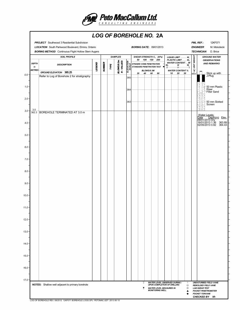
Stick up withJ-Plug
50 mm PlasticRiserFilter Sand
50 mm SlottedScreen
Water Levels:Date Depth(m) Elev.09/01/2013 Dry16/01/2013 1.36 363.8902/05/2013 0.82 364.43
3.0362.3
Refer to Log of Borehole 2 for stratigraphy
BOREHOLE TERMINATED AT 3.0 m
(kPa)
kN/m3
UN
IT W
EIG
HT
LE
GE
ND
LIQUID LIMIT
NU
MB
ER
CHECKED BY
GROUND ELEVATION
PLASTIC LIMIT
South Parkwood Boulevard, Elmira, Ontario
WL
LOCATION
Southwood 3 Residential Subdivision
W
D. Brice
365.25
kh
BORING DATE:
REMOLDED FIELD VANEWATER LEVEL OBSERVED DURING /UPON COMPLETION OF DRILLING
POCKET PENETROMETER
POCKET TORVANE
LAB SHEAR TEST
12KF071
UNDISTURBED FIELD VANE
WATER LEVEL MEASURED INMONITORING WELL
Shallow well adjacent to primary borehole
PML REF.:
BL
OW
S/0
.3m
N -
VA
LU
ES
LOG OF BOREHOLE NO. 2A
10 20 30
NU
MB
ER
SOIL PROFILE
20 40 60 80
TECHNICIAN
DESCRIPTIONDEPTH
in
METRES
NOTES:
M. Molodecki
PROJECT
GROUND WATER
OBSERVATIONS
AND REMARKS
LE
GE
ND
SAMPLES
TY
PE WP
WATER CONTENT
50 100 150 200
0.0365
364
363
09/01/2013 ENGINEER
1.0
2.0
3.0
4.0
5.0
6.0
7.0
8.0
9.0
10.0
11.0
12.0
13.0
14.0
15.0
16.0
17.0
BLOWS/0.3M
BORING METHOD
WATER CONTENT %365.25
W
WL
Continuous Flight Hollow Stem Augers
GROUND ELEVATION
TY
PE
SHEAR STRENGTH Cu
DYNAMIC CONE PENETRATION
STANDARD PENETRATION TEST
BL
OW
S/0
.3m
N -
VA
LU
ES
EL
EV
AT
ION
SC
AL
E
WP
LOG OF BOREHOLE REV. 08/2012 12KF071 BOREHOLE LOGS.GPJ PETOMAC.GDT 2013 06 10
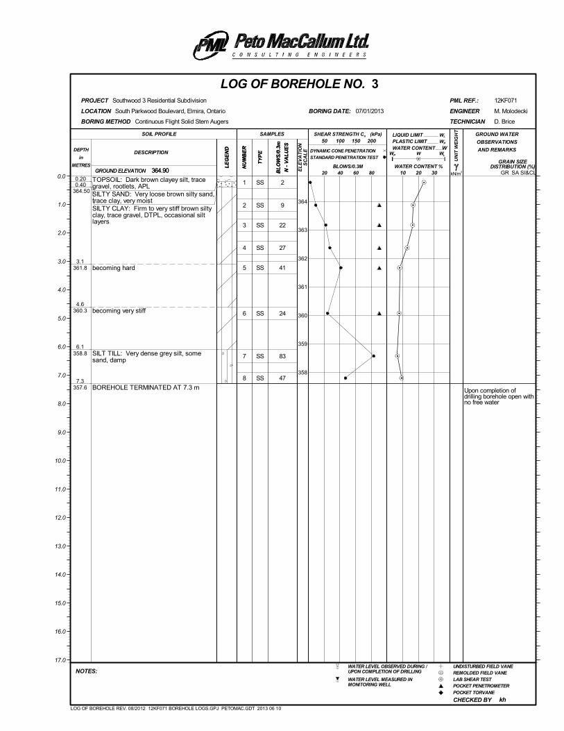
1
2
3
4
5
6
7
8
SS
SS
SS
SS
SS
SS
SS
SS
2
9
22
27
41
24
83
47
Upon completion ofdrilling borehole open withno free water
0.200.40
364.50
3.1361.8
4.6360.3
6.1358.8
7.3357.6
TOPSOIL: Dark brown clayey silt, tracegravel, rootlets, APLSILTY SAND: Very loose brown silty sand,trace clay, very moistSILTY CLAY: Firm to very stiff brown siltyclay, trace gravel, DTPL, occasional siltlayers
becoming hard
becoming very stiff
SILT TILL: Very dense grey silt, somesand, damp
BOREHOLE TERMINATED AT 7.3 m
(kPa)
kN/m3
UN
IT W
EIG
HT
LE
GE
ND
LIQUID LIMIT
NU
MB
ER
CHECKED BY
GRAIN SIZEDISTRIBUTION (%)
GROUND ELEVATION
PLASTIC LIMIT
SA SI&CL
South Parkwood Boulevard, Elmira, Ontario
WL
LOCATION
Southwood 3 Residential Subdivision
W
D. Brice
364.90
kh
BORING DATE:
REMOLDED FIELD VANEWATER LEVEL OBSERVED DURING /UPON COMPLETION OF DRILLING
POCKET PENETROMETER
POCKET TORVANE
LAB SHEAR TEST
12KF071
UNDISTURBED FIELD VANE
WATER LEVEL MEASURED INMONITORING WELL
PML REF.:
BL
OW
S/0
.3m
N -
VA
LU
ES
LOG OF BOREHOLE NO. 3
10 20 30
NU
MB
ER
SOIL PROFILE
20 40 60 80
TECHNICIAN
DESCRIPTIONDEPTH
in
METRES
NOTES:
M. Molodecki
PROJECT
GROUND WATER
OBSERVATIONS
AND REMARKS
LE
GE
ND
SAMPLES
TY
PE WP
WATER CONTENT
50 100 150 200
0.0
364
363
362
361
360
359
358
07/01/2013 ENGINEER
1.0
2.0
3.0
4.0
5.0
6.0
7.0
8.0
9.0
10.0
11.0
12.0
13.0
14.0
15.0
16.0
17.0
BLOWS/0.3M
BORING METHOD
WATER CONTENT %364.90
W
WL
Continuous Flight Solid Stem Augers
GROUND ELEVATION
TY
PE
SHEAR STRENGTH Cu
DYNAMIC CONE PENETRATION
STANDARD PENETRATION TEST
BL
OW
S/0
.3m
N -
VA
LU
ES
EL
EV
AT
ION
SC
AL
E
WP
GR
LOG OF BOREHOLE REV. 08/2012 12KF071 BOREHOLE LOGS.GPJ PETOMAC.GDT 2013 06 10
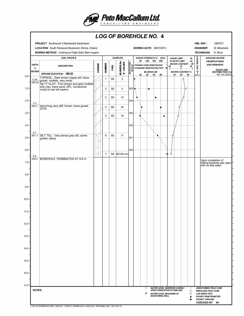
1
2
3
4
5
6
7
SS
SS
SS
SS
SS
SS
SS
3
4
10
24
19
71
50/125 mm
Upon completion ofdrilling borehole was openwith no free water
0.38 365.62
2.3363.7
4.7361.3
6.6359.4
TOPSOIL: Dark brown clayey silt, tracegravel, rootlets, very moistSILTY CLAY: Firm brown and grey mottledsilty clay, trace sand, APL, occasionalmoist to wet silt seams
becoming very stiff, brown, trace gravel,DTPL
SILT TILL: Very dense grey silt, somegravel, damp
BOREHOLE TERMINATED AT 6.6 m
(kPa)
kN/m3
UN
IT W
EIG
HT
LE
GE
ND
LIQUID LIMIT
NU
MB
ER
CHECKED BY
GRAIN SIZEDISTRIBUTION (%)
GROUND ELEVATION
PLASTIC LIMIT
SA SI&CL
South Parkwood Boulevard, Elmira, Ontario
WL
LOCATION
Southwood 3 Residential Subdivision
W
D. Brice
366.00
kh
BORING DATE:
REMOLDED FIELD VANEWATER LEVEL OBSERVED DURING /UPON COMPLETION OF DRILLING
POCKET PENETROMETER
POCKET TORVANE
LAB SHEAR TEST
12KF071
UNDISTURBED FIELD VANE
WATER LEVEL MEASURED INMONITORING WELL
PML REF.:
BL
OW
S/0
.3m
N -
VA
LU
ES
LOG OF BOREHOLE NO. 4
10 20 30
NU
MB
ER
SOIL PROFILE
20 40 60 80
TECHNICIAN
DESCRIPTIONDEPTH
in
METRES
NOTES:
M. Molodecki
PROJECT
GROUND WATER
OBSERVATIONS
AND REMARKS
LE
GE
ND
SAMPLES
TY
PE WP
WATER CONTENT
50 100 150 200
0.0
365
364
363
362
361
360
09/01/2013 ENGINEER
1.0
2.0
3.0
4.0
5.0
6.0
7.0
8.0
9.0
10.0
11.0
12.0
13.0
14.0
15.0
16.0
17.0
BLOWS/0.3M
BORING METHOD
WATER CONTENT %366.00
W
WL
Continuous Flight Solid Stem Augers
GROUND ELEVATION
TY
PE
SHEAR STRENGTH Cu
DYNAMIC CONE PENETRATION
STANDARD PENETRATION TEST
BL
OW
S/0
.3m
N -
VA
LU
ES
EL
EV
AT
ION
SC
AL
E
WP
GR
LOG OF BOREHOLE REV. 08/2012 12KF071 BOREHOLE LOGS.GPJ PETOMAC.GDT 2013 06 10
>>
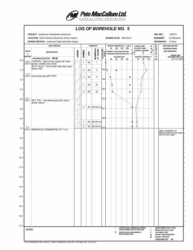
1
2
3
4
5
6
7
8
SS
SS
SS
SS
SS
SS
SS
SS
1
5
17
24
25
50/150 mm
50/125 mm
50/125 mm
Upon completion ofdrilling borehole was openwith no free water
0.25 365.70
1.5364.5
4.0362.0
7.0359.0
TOPSOIL: Dark brown clayey silt, tracegravel, rootlets very moistSILTY CLAY: Firm brown silty clay, tracegravel, APL
becoming very stiff, DTPL
SILT TILL: Very dense grey silt, somegravel, damp
BOREHOLE TERMINATED AT 7.0 m
(kPa)
kN/m3
UN
IT W
EIG
HT
LE
GE
ND
LIQUID LIMIT
NU
MB
ER
CHECKED BY
GRAIN SIZEDISTRIBUTION (%)
GROUND ELEVATION
PLASTIC LIMIT
SA SI&CL
South Parkwood Boulevard, Elmira, Ontario
WL
LOCATION
Southwood 3 Residential Subdivision
W
D. Brice
365.95
kh
BORING DATE:
REMOLDED FIELD VANEWATER LEVEL OBSERVED DURING /UPON COMPLETION OF DRILLING
POCKET PENETROMETER
POCKET TORVANE
LAB SHEAR TEST
12KF071
UNDISTURBED FIELD VANE
WATER LEVEL MEASURED INMONITORING WELL
PML REF.:
BL
OW
S/0
.3m
N -
VA
LU
ES
LOG OF BOREHOLE NO. 5
10 20 30
NU
MB
ER
SOIL PROFILE
20 40 60 80
TECHNICIAN
DESCRIPTIONDEPTH
in
METRES
NOTES:
M. Molodecki
PROJECT
GROUND WATER
OBSERVATIONS
AND REMARKS
LE
GE
ND
SAMPLES
TY
PE WP
WATER CONTENT
50 100 150 200
0.0
365
364
363
362
361
360
359
08/01/2013 ENGINEER
1.0
2.0
3.0
4.0
5.0
6.0
7.0
8.0
9.0
10.0
11.0
12.0
13.0
14.0
15.0
16.0
17.0
BLOWS/0.3M
BORING METHOD
WATER CONTENT %365.95
W
WL
Continuous Flight Solid Stem Augers
GROUND ELEVATION
TY
PE
SHEAR STRENGTH Cu
DYNAMIC CONE PENETRATION
STANDARD PENETRATION TEST
BL
OW
S/0
.3m
N -
VA
LU
ES
EL
EV
AT
ION
SC
AL
E
WP
GR
LOG OF BOREHOLE REV. 08/2012 12KF071 BOREHOLE LOGS.GPJ PETOMAC.GDT 2013 06 10
>>
>>
>>
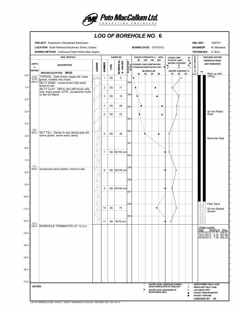
1
2
3
4
5
6
7
8
9
10
11
SS
SS
SS
SS
SS
SS
SS
SS
SS
SS
SS
5
11
16
28
23
39
50/150 mm
50/125 mm
50/150 mm
74
50/75 mm
Stick up withJ-Plug
50 mm PlasticRiser
Bentonite Seal
Filter Sand
50 mm SlottedScreen
Water Levels:Date Depth(m) Elev.07/01/2013 11.73 354.8716/01/2013 8.74 357.8602/05/2013 7.28 359.32
0.230.33
366.27
4.6362.0
7.6359.0
12.3354.3
TOPSOIL: Dark brown clayey silt, tracegravel, rootlets very moistSILTY SAND: Loose brown silty sand,moist to wetSILTY CLAY: Stiff to very stiff brown siltyclay, trace gravel, DTPL, occasional moistto wet silt layers
SILT TILL: Dense to very dense grey silt,some gravel, some sand, damp
occasional sand seams, moist to wet
BOREHOLE TERMINATED AT 12.3 m
(kPa)
kN/m3
UN
IT W
EIG
HT
LE
GE
ND
LIQUID LIMIT
NU
MB
ER
CHECKED BY
GROUND ELEVATION
PLASTIC LIMIT
South Parkwood Boulevard, Elmira, Ontario
WL
LOCATION
Southwood 3 Residential Subdivision
W
D. Brice
366.60
kh
BORING DATE:
REMOLDED FIELD VANEWATER LEVEL OBSERVED DURING /UPON COMPLETION OF DRILLING
POCKET PENETROMETER
POCKET TORVANE
LAB SHEAR TEST
12KF071
UNDISTURBED FIELD VANE
WATER LEVEL MEASURED INMONITORING WELL
PML REF.:
BL
OW
S/0
.3m
N -
VA
LU
ES
LOG OF BOREHOLE NO. 6
10 20 30
NU
MB
ER
SOIL PROFILE
20 40 60 80
TECHNICIAN
DESCRIPTIONDEPTH
in
METRES
NOTES:
M. Molodecki
PROJECT
GROUND WATER
OBSERVATIONS
AND REMARKS
LE
GE
ND
SAMPLES
TY
PE WP
WATER CONTENT
50 100 150 200
0.0
366
365
364
363
362
361
360
359
358
357
356
355
07/01/2013 ENGINEER
1.0
2.0
3.0
4.0
5.0
6.0
7.0
8.0
9.0
10.0
11.0
12.0
13.0
14.0
15.0
16.0
17.0
BLOWS/0.3M
BORING METHOD
WATER CONTENT %366.60
W
WL
Continuous Flight Hollow Stem Augers
GROUND ELEVATION
TY
PE
SHEAR STRENGTH Cu
DYNAMIC CONE PENETRATION
STANDARD PENETRATION TEST
BL
OW
S/0
.3m
N -
VA
LU
ES
EL
EV
AT
ION
SC
AL
E
WP
LOG OF BOREHOLE REV. 08/2012 12KF071 BOREHOLE LOGS.GPJ PETOMAC.GDT 2013 06 10
>>
>>
>>
>>
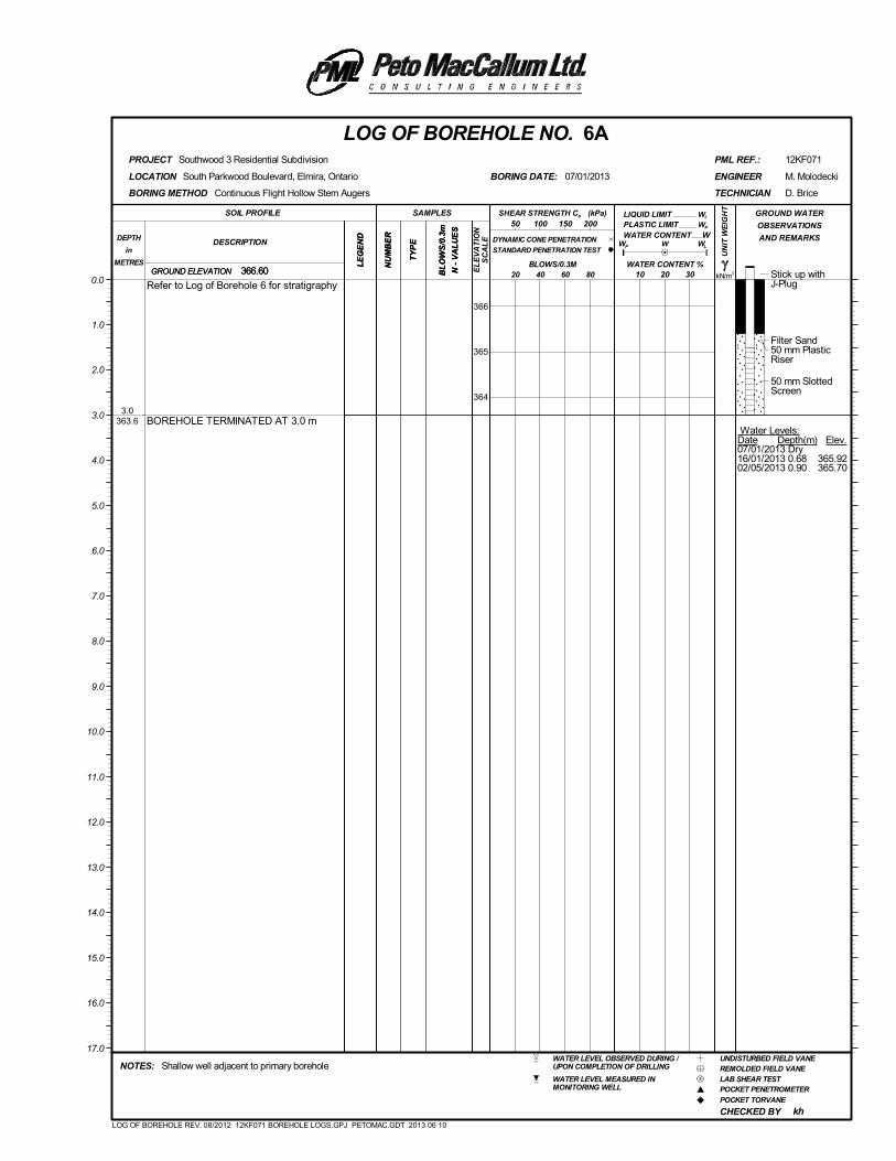
Stick up withJ-Plug
Filter Sand50 mm PlasticRiser
50 mm SlottedScreen
Water Levels:Date Depth(m) Elev.07/01/2013 Dry16/01/2013 0.68 365.9202/05/2013 0.90 365.70
3.0363.6
Refer to Log of Borehole 6 for stratigraphy
BOREHOLE TERMINATED AT 3.0 m
(kPa)
kN/m3
UN
IT W
EIG
HT
LE
GE
ND
LIQUID LIMIT
NU
MB
ER
CHECKED BY
GROUND ELEVATION
PLASTIC LIMIT
South Parkwood Boulevard, Elmira, Ontario
WL
LOCATION
Southwood 3 Residential Subdivision
W
D. Brice
366.60
kh
BORING DATE:
REMOLDED FIELD VANEWATER LEVEL OBSERVED DURING /UPON COMPLETION OF DRILLING
POCKET PENETROMETER
POCKET TORVANE
LAB SHEAR TEST
12KF071
UNDISTURBED FIELD VANE
WATER LEVEL MEASURED INMONITORING WELL
Shallow well adjacent to primary borehole
PML REF.:
BL
OW
S/0
.3m
N -
VA
LU
ES
LOG OF BOREHOLE NO. 6A
10 20 30
NU
MB
ER
SOIL PROFILE
20 40 60 80
TECHNICIAN
DESCRIPTIONDEPTH
in
METRES
NOTES:
M. Molodecki
PROJECT
GROUND WATER
OBSERVATIONS
AND REMARKS
LE
GE
ND
SAMPLES
TY
PE WP
WATER CONTENT
50 100 150 200
0.0
366
365
364
07/01/2013 ENGINEER
1.0
2.0
3.0
4.0
5.0
6.0
7.0
8.0
9.0
10.0
11.0
12.0
13.0
14.0
15.0
16.0
17.0
BLOWS/0.3M
BORING METHOD
WATER CONTENT %366.60
W
WL
Continuous Flight Hollow Stem Augers
GROUND ELEVATION
TY
PE
SHEAR STRENGTH Cu
DYNAMIC CONE PENETRATION
STANDARD PENETRATION TEST
BL
OW
S/0
.3m
N -
VA
LU
ES
EL
EV
AT
ION
SC
AL
E
WP
LOG OF BOREHOLE REV. 08/2012 12KF071 BOREHOLE LOGS.GPJ PETOMAC.GDT 2013 06 10
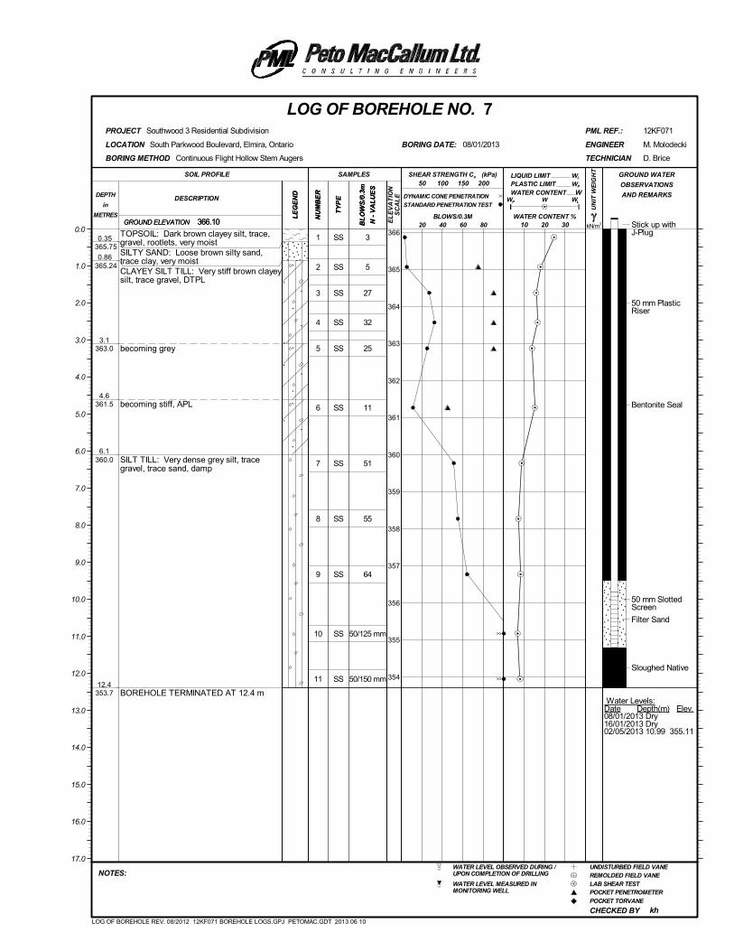
1
2
3
4
5
6
7
8
9
10
11
SS
SS
SS
SS
SS
SS
SS
SS
SS
SS
SS
3
5
27
32
25
11
51
55
64
50/125 mm
50/150 mm
Stick up withJ-Plug
50 mm PlasticRiser
Bentonite Seal
50 mm SlottedScreen
Filter Sand
Sloughed Native
Water Levels:Date Depth(m) Elev.08/01/2013 Dry16/01/2013 Dry02/05/2013 10.99 355.11
0.35 365.75
0.86 365.24
3.1363.0
4.6361.5
6.1360.0
12.4353.7
TOPSOIL: Dark brown clayey silt, trace,gravel, rootlets, very moistSILTY SAND: Loose brown silty sand,trace clay, very moistCLAYEY SILT TILL: Very stiff brown clayeysilt, trace gravel, DTPL
becoming grey
becoming stiff, APL
SILT TILL: Very dense grey silt, tracegravel, trace sand, damp
BOREHOLE TERMINATED AT 12.4 m
(kPa)
kN/m3
UN
IT W
EIG
HT
LE
GE
ND
LIQUID LIMIT
NU
MB
ER
CHECKED BY
GROUND ELEVATION
PLASTIC LIMIT
South Parkwood Boulevard, Elmira, Ontario
WL
LOCATION
Southwood 3 Residential Subdivision
W
D. Brice
366.10
kh
BORING DATE:
REMOLDED FIELD VANEWATER LEVEL OBSERVED DURING /UPON COMPLETION OF DRILLING
POCKET PENETROMETER
POCKET TORVANE
LAB SHEAR TEST
12KF071
UNDISTURBED FIELD VANE
WATER LEVEL MEASURED INMONITORING WELL
PML REF.:
BL
OW
S/0
.3m
N -
VA
LU
ES
LOG OF BOREHOLE NO. 7
10 20 30
NU
MB
ER
SOIL PROFILE
20 40 60 80
TECHNICIAN
DESCRIPTIONDEPTH
in
METRES
NOTES:
M. Molodecki
PROJECT
GROUND WATER
OBSERVATIONS
AND REMARKS
LE
GE
ND
SAMPLES
TY
PE WP
WATER CONTENT
50 100 150 200
0.0 366
365
364
363
362
361
360
359
358
357
356
355
354
08/01/2013 ENGINEER
1.0
2.0
3.0
4.0
5.0
6.0
7.0
8.0
9.0
10.0
11.0
12.0
13.0
14.0
15.0
16.0
17.0
BLOWS/0.3M
BORING METHOD
WATER CONTENT %366.10
W
WL
Continuous Flight Hollow Stem Augers
GROUND ELEVATION
TY
PE
SHEAR STRENGTH Cu
DYNAMIC CONE PENETRATION
STANDARD PENETRATION TEST
BL
OW
S/0
.3m
N -
VA
LU
ES
EL
EV
AT
ION
SC
AL
E
WP
LOG OF BOREHOLE REV. 08/2012 12KF071 BOREHOLE LOGS.GPJ PETOMAC.GDT 2013 06 10
>>
>>
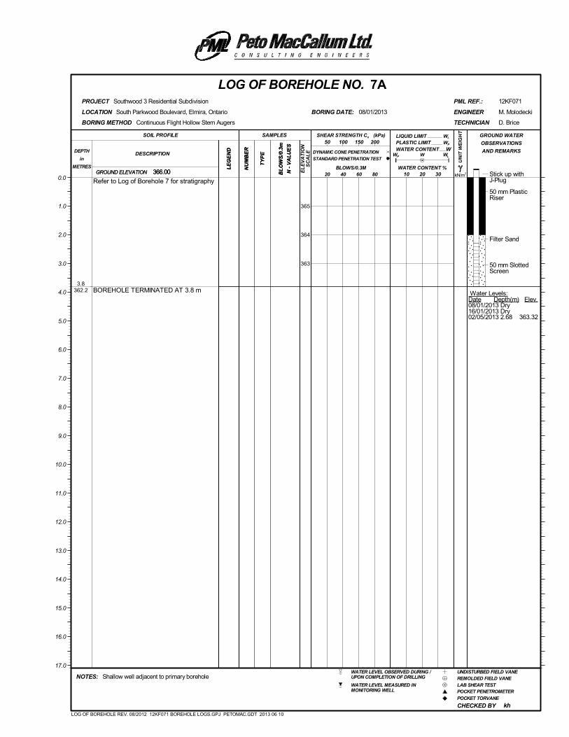
Stick up withJ-Plug
50 mm PlasticRiser
Filter Sand
50 mm SlottedScreen
Water Levels:Date Depth(m) Elev.08/01/2013 Dry16/01/2013 Dry02/05/2013 2.68 363.32
3.8362.2
Refer to Log of Borehole 7 for stratigraphy
BOREHOLE TERMINATED AT 3.8 m
(kPa)
kN/m3
UN
IT W
EIG
HT
LE
GE
ND
LIQUID LIMIT
NU
MB
ER
CHECKED BY
GROUND ELEVATION
PLASTIC LIMIT
South Parkwood Boulevard, Elmira, Ontario
WL
LOCATION
Southwood 3 Residential Subdivision
W
D. Brice
366.00
kh
BORING DATE:
REMOLDED FIELD VANEWATER LEVEL OBSERVED DURING /UPON COMPLETION OF DRILLING
POCKET PENETROMETER
POCKET TORVANE
LAB SHEAR TEST
12KF071
UNDISTURBED FIELD VANE
WATER LEVEL MEASURED INMONITORING WELL
Shallow well adjacent to primary borehole
PML REF.:
BL
OW
S/0
.3m
N -
VA
LU
ES
LOG OF BOREHOLE NO. 7A
10 20 30
NU
MB
ER
SOIL PROFILE
20 40 60 80
TECHNICIAN
DESCRIPTIONDEPTH
in
METRES
NOTES:
M. Molodecki
PROJECT
GROUND WATER
OBSERVATIONS
AND REMARKS
LE
GE
ND
SAMPLES
TY
PE WP
WATER CONTENT
50 100 150 200
0.0
365
364
363
08/01/2013 ENGINEER
1.0
2.0
3.0
4.0
5.0
6.0
7.0
8.0
9.0
10.0
11.0
12.0
13.0
14.0
15.0
16.0
17.0
BLOWS/0.3M
BORING METHOD
WATER CONTENT %366.00
W
WL
Continuous Flight Hollow Stem Augers
GROUND ELEVATION
TY
PE
SHEAR STRENGTH Cu
DYNAMIC CONE PENETRATION
STANDARD PENETRATION TEST
BL
OW
S/0
.3m
N -
VA
LU
ES
EL
EV
AT
ION
SC
AL
E
WP
LOG OF BOREHOLE REV. 08/2012 12KF071 BOREHOLE LOGS.GPJ PETOMAC.GDT 2013 06 10
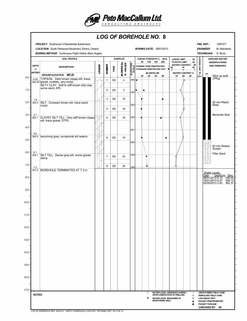
1
2
3
4
5
6
7
8
SS
SS
SS
SS
SS
SS
SS
SS
4
3
19
18
18
19
33
34
Stick up wothJ-Plug
50 mm PlasticRiser
Bentonite Seal
50 mm SlottedScreen
Filter Sand
Water Levels:Date Depth(m) Elev.08/01/2013 6.15 359.0516/01/2013 6.07 359.1302/05/2013 2.83 362.37
0.25 364.95
1.9363.3
3.1362.1
4.6360.6
6.1359.1
7.3357.9
TOPSOIL: Dark brown clayey silt, trace,gravel, rootlets, very moistSILTY CLAY: Soft to stiff brown silty clay,some sand, APL
SILT: Compact brown silt, trace sand,moist
CLAYEY SILT TILL: Very stiff brown clayeysilt, trace gravel, DTPL
becoming grey, occasional silt seams
SILT TILL: Dense grey silt, some gravel,damp
BOREHOLE TERMINATED AT 7.3 m
(kPa)
kN/m3
UN
IT W
EIG
HT
LE
GE
ND
LIQUID LIMIT
NU
MB
ER
CHECKED BY
GROUND ELEVATION
PLASTIC LIMIT
South Parkwood Boulevard, Elmira, Ontario
WL
LOCATION
Southwood 3 Residential Subdivision
W
D. Brice
365.20
kh
BORING DATE:
REMOLDED FIELD VANEWATER LEVEL OBSERVED DURING /UPON COMPLETION OF DRILLING
POCKET PENETROMETER
POCKET TORVANE
LAB SHEAR TEST
12KF071
UNDISTURBED FIELD VANE
WATER LEVEL MEASURED INMONITORING WELL
PML REF.:
BL
OW
S/0
.3m
N -
VA
LU
ES
LOG OF BOREHOLE NO. 8
10 20 30
NU
MB
ER
SOIL PROFILE
20 40 60 80
TECHNICIAN
DESCRIPTIONDEPTH
in
METRES
NOTES:
M. Molodecki
PROJECT
GROUND WATER
OBSERVATIONS
AND REMARKS
LE
GE
ND
SAMPLES
TY
PE WP
WATER CONTENT
50 100 150 200
0.0365
364
363
362
361
360
359
358
08/01/2013 ENGINEER
1.0
2.0
3.0
4.0
5.0
6.0
7.0
8.0
9.0
10.0
11.0
12.0
13.0
14.0
15.0
16.0
17.0
BLOWS/0.3M
BORING METHOD
WATER CONTENT %365.20
W
WL
Continuous Flight Hollow Stem Augers
GROUND ELEVATION
TY
PE
SHEAR STRENGTH Cu
DYNAMIC CONE PENETRATION
STANDARD PENETRATION TEST
BL
OW
S/0
.3m
N -
VA
LU
ES
EL
EV
AT
ION
SC
AL
E
WP
LOG OF BOREHOLE REV. 08/2012 12KF071 BOREHOLE LOGS.GPJ PETOMAC.GDT 2013 06 10
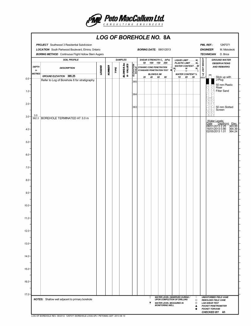
Stick up withJ-Plug
50 mm PlasticRiserFilter Sand
50 mm SlottedScreen
Water Levels:Date Depth(m) Elev.08/01/2013 2.25 363.0016/01/2013 0.86 364.3902/05/2013 1.01 364.24
3.0362.3
Refer to Log of Borehole 8 for stratigraphy
BOREHOLE TERMINATED AT 3.0 m
(kPa)
kN/m3
UN
IT W
EIG
HT
LE
GE
ND
LIQUID LIMIT
NU
MB
ER
CHECKED BY
GROUND ELEVATION
PLASTIC LIMIT
South Parkwood Boulevard, Elmira, Ontario
WL
LOCATION
Southwood 3 Residential Subdivision
W
D. Brice
365.25
kh
BORING DATE:
REMOLDED FIELD VANEWATER LEVEL OBSERVED DURING /UPON COMPLETION OF DRILLING
POCKET PENETROMETER
POCKET TORVANE
LAB SHEAR TEST
12KF071
UNDISTURBED FIELD VANE
WATER LEVEL MEASURED INMONITORING WELL
Shallow well adjacent to primary borehole
PML REF.:
BL
OW
S/0
.3m
N -
VA
LU
ES
LOG OF BOREHOLE NO. 8A
10 20 30
NU
MB
ER
SOIL PROFILE
20 40 60 80
TECHNICIAN
DESCRIPTIONDEPTH
in
METRES
NOTES:
M. Molodecki
PROJECT
GROUND WATER
OBSERVATIONS
AND REMARKS
LE
GE
ND
SAMPLES
TY
PE WP
WATER CONTENT
50 100 150 200
0.0365
364
363
08/01/2013 ENGINEER
1.0
2.0
3.0
4.0
5.0
6.0
7.0
8.0
9.0
10.0
11.0
12.0
13.0
14.0
15.0
16.0
17.0
BLOWS/0.3M
BORING METHOD
WATER CONTENT %365.25
W
WL
Continuous Flight Hollow Stem Augers
GROUND ELEVATION
TY
PE
SHEAR STRENGTH Cu
DYNAMIC CONE PENETRATION
STANDARD PENETRATION TEST
BL
OW
S/0
.3m
N -
VA
LU
ES
EL
EV
AT
ION
SC
AL
E
WP
LOG OF BOREHOLE REV. 08/2012 12KF071 BOREHOLE LOGS.GPJ PETOMAC.GDT 2013 06 10
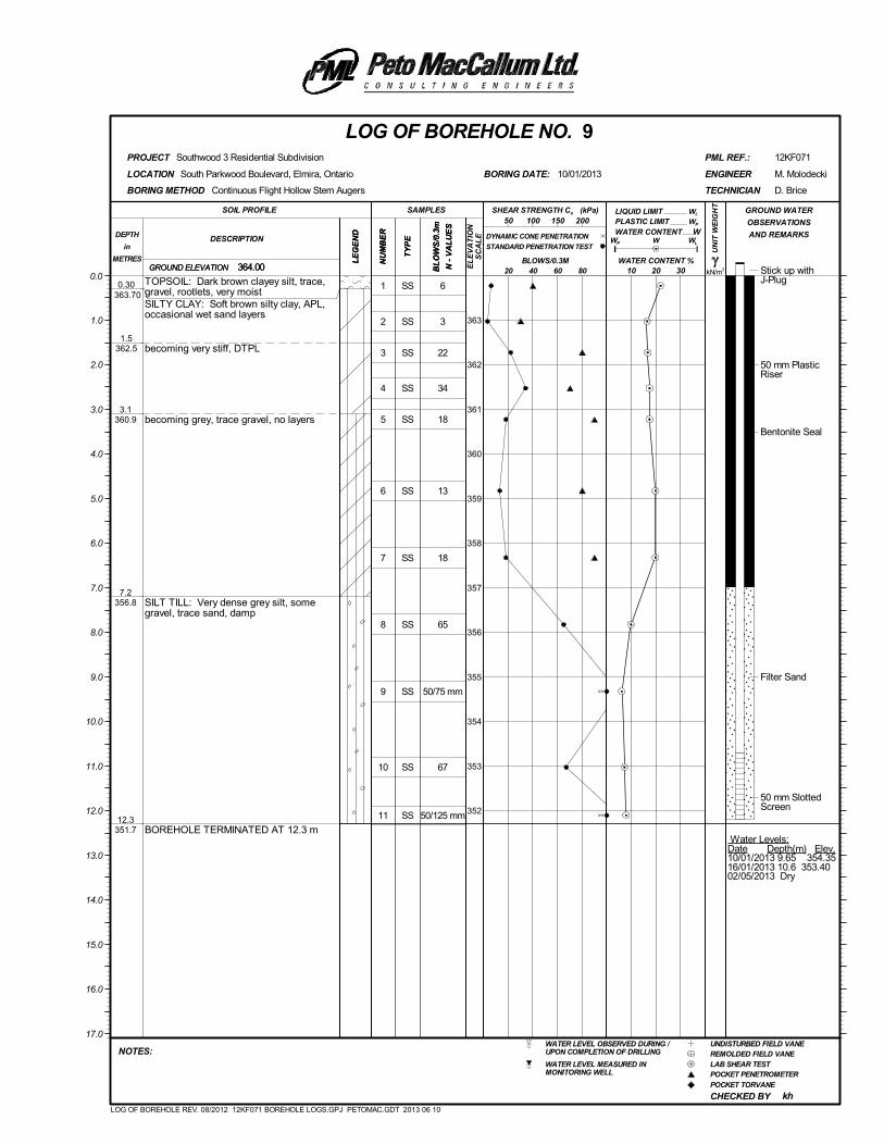
1
2
3
4
5
6
7
8
9
10
11
SS
SS
SS
SS
SS
SS
SS
SS
SS
SS
SS
6
3
22
34
18
13
18
65
50/75 mm
67
50/125 mm
Stick up withJ-Plug
50 mm PlasticRiser
Bentonite Seal
Filter Sand
50 mm SlottedScreen
Water Levels:Date Depth(m) Elev.10/01/2013 9.65 354.3516/01/2013 10.6 353.4002/05/2013 Dry
0.30 363.70
1.5362.5
3.1360.9
7.2356.8
12.3351.7
TOPSOIL: Dark brown clayey silt, trace,gravel, rootlets, very moistSILTY CLAY: Soft brown silty clay, APL,occasional wet sand layers
becoming very stiff, DTPL
becoming grey, trace gravel, no layers
SILT TILL: Very dense grey silt, somegravel, trace sand, damp
BOREHOLE TERMINATED AT 12.3 m
(kPa)
kN/m3
UN
IT W
EIG
HT
LE
GE
ND
LIQUID LIMIT
NU
MB
ER
CHECKED BY
GROUND ELEVATION
PLASTIC LIMIT
South Parkwood Boulevard, Elmira, Ontario
WL
LOCATION
Southwood 3 Residential Subdivision
W
D. Brice
364.00
kh
BORING DATE:
REMOLDED FIELD VANEWATER LEVEL OBSERVED DURING /UPON COMPLETION OF DRILLING
POCKET PENETROMETER
POCKET TORVANE
LAB SHEAR TEST
12KF071
UNDISTURBED FIELD VANE
WATER LEVEL MEASURED INMONITORING WELL
PML REF.:
BL
OW
S/0
.3m
N -
VA
LU
ES
LOG OF BOREHOLE NO. 9
10 20 30
NU
MB
ER
SOIL PROFILE
20 40 60 80
TECHNICIAN
DESCRIPTIONDEPTH
in
METRES
NOTES:
M. Molodecki
PROJECT
GROUND WATER
OBSERVATIONS
AND REMARKS
LE
GE
ND
SAMPLES
TY
PE WP
WATER CONTENT
50 100 150 200
0.0
363
362
361
360
359
358
357
356
355
354
353
352
10/01/2013 ENGINEER
1.0
2.0
3.0
4.0
5.0
6.0
7.0
8.0
9.0
10.0
11.0
12.0
13.0
14.0
15.0
16.0
17.0
BLOWS/0.3M
BORING METHOD
WATER CONTENT %364.00
W
WL
Continuous Flight Hollow Stem Augers
GROUND ELEVATION
TY
PE
SHEAR STRENGTH Cu
DYNAMIC CONE PENETRATION
STANDARD PENETRATION TEST
BL
OW
S/0
.3m
N -
VA
LU
ES
EL
EV
AT
ION
SC
AL
E
WP
LOG OF BOREHOLE REV. 08/2012 12KF071 BOREHOLE LOGS.GPJ PETOMAC.GDT 2013 06 10
>>
>>
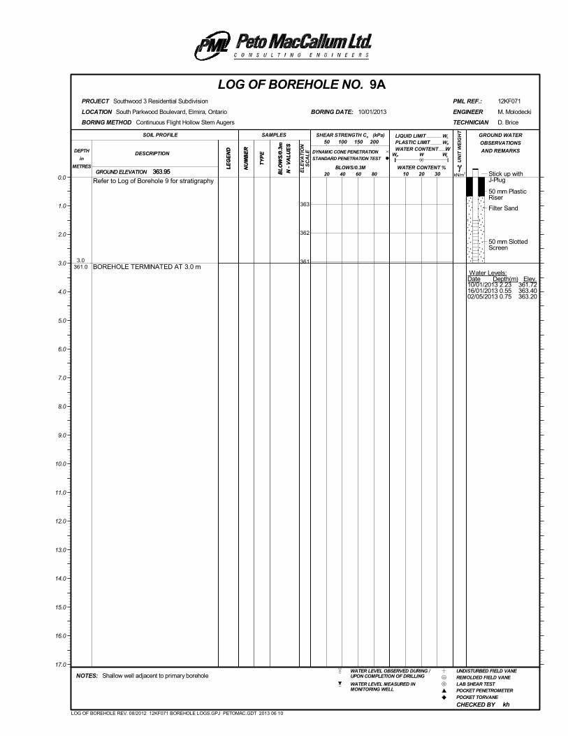
Stick up withJ-Plug
50 mm PlasticRiser
Filter Sand
50 mm SlottedScreen
Water Levels:Date Depth(m) Elev.10/01/2013 2.23 361.7216/01/2013 0.55 363.4002/05/2013 0.75 363.20
3.0361.0
Refer to Log of Borehole 9 for stratigraphy
BOREHOLE TERMINATED AT 3.0 m
(kPa)
kN/m3
UN
IT W
EIG
HT
LE
GE
ND
LIQUID LIMIT
NU
MB
ER
CHECKED BY
GROUND ELEVATION
PLASTIC LIMIT
South Parkwood Boulevard, Elmira, Ontario
WL
LOCATION
Southwood 3 Residential Subdivision
W
D. Brice
363.95
kh
BORING DATE:
REMOLDED FIELD VANEWATER LEVEL OBSERVED DURING /UPON COMPLETION OF DRILLING
POCKET PENETROMETER
POCKET TORVANE
LAB SHEAR TEST
12KF071
UNDISTURBED FIELD VANE
WATER LEVEL MEASURED INMONITORING WELL
Shallow well adjacent to primary borehole
PML REF.:
BL
OW
S/0
.3m
N -
VA
LU
ES
LOG OF BOREHOLE NO. 9A
10 20 30
NU
MB
ER
SOIL PROFILE
20 40 60 80
TECHNICIAN
DESCRIPTIONDEPTH
in
METRES
NOTES:
M. Molodecki
PROJECT
GROUND WATER
OBSERVATIONS
AND REMARKS
LE
GE
ND
SAMPLES
TY
PE WP
WATER CONTENT
50 100 150 200
0.0
363
362
361
10/01/2013 ENGINEER
1.0
2.0
3.0
4.0
5.0
6.0
7.0
8.0
9.0
10.0
11.0
12.0
13.0
14.0
15.0
16.0
17.0
BLOWS/0.3M
BORING METHOD
WATER CONTENT %363.95
W
WL
Continuous Flight Hollow Stem Augers
GROUND ELEVATION
TY
PE
SHEAR STRENGTH Cu
DYNAMIC CONE PENETRATION
STANDARD PENETRATION TEST
BL
OW
S/0
.3m
N -
VA
LU
ES
EL
EV
AT
ION
SC
AL
E
WP
LOG OF BOREHOLE REV. 08/2012 12KF071 BOREHOLE LOGS.GPJ PETOMAC.GDT 2013 06 10
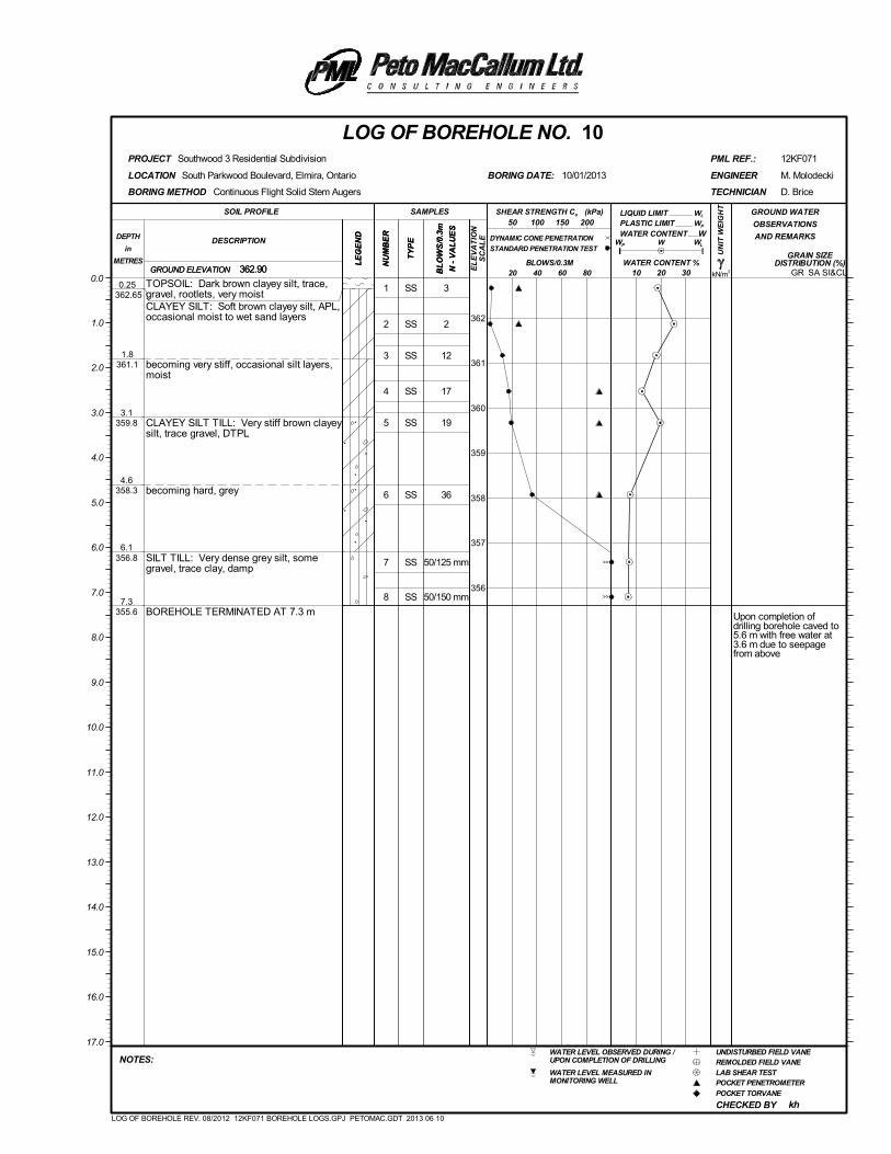
1
2
3
4
5
6
7
8
SS
SS
SS
SS
SS
SS
SS
SS
3
2
12
17
19
36
50/125 mm
50/150 mm
Upon completion ofdrilling borehole caved to5.6 m with free water at3.6 m due to seepagefrom above
0.25 362.65
1.8361.1
3.1359.8
4.6358.3
6.1356.8
7.3355.6
TOPSOIL: Dark brown clayey silt, trace,gravel, rootlets, very moistCLAYEY SILT: Soft brown clayey silt, APL,occasional moist to wet sand layers
becoming very stiff, occasional silt layers,moist
CLAYEY SILT TILL: Very stiff brown clayeysilt, trace gravel, DTPL
becoming hard, grey
SILT TILL: Very dense grey silt, somegravel, trace clay, damp
BOREHOLE TERMINATED AT 7.3 m
(kPa)
kN/m3
UN
IT W
EIG
HT
LE
GE
ND
LIQUID LIMIT
NU
MB
ER
CHECKED BY
GRAIN SIZEDISTRIBUTION (%)
GROUND ELEVATION
PLASTIC LIMIT
SA SI&CL
South Parkwood Boulevard, Elmira, Ontario
WL
LOCATION
Southwood 3 Residential Subdivision
W
D. Brice
362.90
kh
BORING DATE:
REMOLDED FIELD VANEWATER LEVEL OBSERVED DURING /UPON COMPLETION OF DRILLING
POCKET PENETROMETER
POCKET TORVANE
LAB SHEAR TEST
12KF071
UNDISTURBED FIELD VANE
WATER LEVEL MEASURED INMONITORING WELL
PML REF.:
BL
OW
S/0
.3m
N -
VA
LU
ES
LOG OF BOREHOLE NO. 10
10 20 30
NU
MB
ER
SOIL PROFILE
20 40 60 80
TECHNICIAN
DESCRIPTIONDEPTH
in
METRES
NOTES:
M. Molodecki
PROJECT
GROUND WATER
OBSERVATIONS
AND REMARKS
LE
GE
ND
SAMPLES
TY
PE WP
WATER CONTENT
50 100 150 200
0.0
362
361
360
359
358
357
356
10/01/2013 ENGINEER
1.0
2.0
3.0
4.0
5.0
6.0
7.0
8.0
9.0
10.0
11.0
12.0
13.0
14.0
15.0
16.0
17.0
BLOWS/0.3M
BORING METHOD
WATER CONTENT %362.90
W
WL
Continuous Flight Solid Stem Augers
GROUND ELEVATION
TY
PE
SHEAR STRENGTH Cu
DYNAMIC CONE PENETRATION
STANDARD PENETRATION TEST
BL
OW
S/0
.3m
N -
VA
LU
ES
EL
EV
AT
ION
SC
AL
E
WP
GR
LOG OF BOREHOLE REV. 08/2012 12KF071 BOREHOLE LOGS.GPJ PETOMAC.GDT 2013 06 10
>>
>>
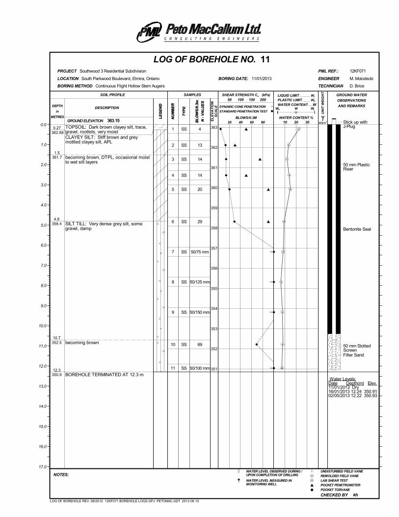
1
2
3
4
5
6
7
8
9
10
11
SS
SS
SS
SS
SS
SS
SS
SS
SS
SS
SS
4
13
14
14
20
29
50/75 mm
50/125 mm
50/150 mm
69
50/100 mm
Stick up withJ-Plug
50 mm PlasticRiser
Bentonite Seal
50 mm SlottedScreenFilter Sand
Water Levels:Date Depth(m) Elev.11/01/2013 Dry16/01/2013 12.24 350.9102/05/2013 12.22 350.93
0.27 362.88
1.5361.7
4.8358.4
10.7352.5
12.3350.9
TOPSOIL: Dark brown clayey silt, trace,gravel, rootlets, very moistCLAYEY SILT: Stiff brown and greymottled clayey silt, APL
becoming brown, DTPL, occasional moistto wet silt layers
SILT TILL: Very dense grey silt, somegravel, damp
becoming brown
BOREHOLE TERMINATED AT 12.3 m
(kPa)
kN/m3
UN
IT W
EIG
HT
LE
GE
ND
LIQUID LIMIT
NU
MB
ER
CHECKED BY
GROUND ELEVATION
PLASTIC LIMIT
South Parkwood Boulevard, Elmira, Ontario
WL
LOCATION
Southwood 3 Residential Subdivision
W
D. Brice
363.15
kh
BORING DATE:
REMOLDED FIELD VANEWATER LEVEL OBSERVED DURING /UPON COMPLETION OF DRILLING
POCKET PENETROMETER
POCKET TORVANE
LAB SHEAR TEST
12KF071
UNDISTURBED FIELD VANE
WATER LEVEL MEASURED INMONITORING WELL
PML REF.:
BL
OW
S/0
.3m
N -
VA
LU
ES
LOG OF BOREHOLE NO. 11
10 20 30
NU
MB
ER
SOIL PROFILE
20 40 60 80
TECHNICIAN
DESCRIPTIONDEPTH
in
METRES
NOTES:
M. Molodecki
PROJECT
GROUND WATER
OBSERVATIONS
AND REMARKS
LE
GE
ND
SAMPLES
TY
PE WP
WATER CONTENT
50 100 150 200
0.0363
362
361
360
359
358
357
356
355
354
353
352
351
11/01/2013 ENGINEER
1.0
2.0
3.0
4.0
5.0
6.0
7.0
8.0
9.0
10.0
11.0
12.0
13.0
14.0
15.0
16.0
17.0
BLOWS/0.3M
BORING METHOD
WATER CONTENT %363.15
W
WL
Continuous Flight Hollow Stem Augers
GROUND ELEVATION
TY
PE
SHEAR STRENGTH Cu
DYNAMIC CONE PENETRATION
STANDARD PENETRATION TEST
BL
OW
S/0
.3m
N -
VA
LU
ES
EL
EV
AT
ION
SC
AL
E
WP
LOG OF BOREHOLE REV. 08/2012 12KF071 BOREHOLE LOGS.GPJ PETOMAC.GDT 2013 06 10
>>
>>
>>
>>
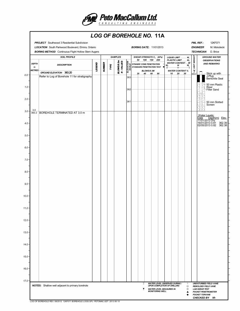
Stick up withJ-PlugBentonite Seal
50 mm PlasticRiserFilter Sand
50 mm SlottedScreen
Water Levels:Date Depth(m) Elev.11/01/2013 Dry16/01/2013 0.81 362.3902/05/2013 0.82 362.38
3.0360.2
Refer to Log of Borehole 11 for stratigraphy
BOREHOLE TERMINATED AT 3.0 m
(kPa)
kN/m3
UN
IT W
EIG
HT
LE
GE
ND
LIQUID LIMIT
NU
MB
ER
CHECKED BY
GROUND ELEVATION
PLASTIC LIMIT
South Parkwood Boulevard, Elmira, Ontario
WL
LOCATION
Southwood 3 Residential Subdivision
W
D. Brice
363.20
kh
BORING DATE:
REMOLDED FIELD VANEWATER LEVEL OBSERVED DURING /UPON COMPLETION OF DRILLING
POCKET PENETROMETER
POCKET TORVANE
LAB SHEAR TEST
12KF071
UNDISTURBED FIELD VANE
WATER LEVEL MEASURED INMONITORING WELL
Shallow well adjacent to primary borehole
PML REF.:
BL
OW
S/0
.3m
N -
VA
LU
ES
LOG OF BOREHOLE NO. 11A
10 20 30
NU
MB
ER
SOIL PROFILE
20 40 60 80
TECHNICIAN
DESCRIPTIONDEPTH
in
METRES
NOTES:
M. Molodecki
PROJECT
GROUND WATER
OBSERVATIONS
AND REMARKS
LE
GE
ND
SAMPLES
TY
PE WP
WATER CONTENT
50 100 150 200
0.0363
362
361
11/01/2013 ENGINEER
1.0
2.0
3.0
4.0
5.0
6.0
7.0
8.0
9.0
10.0
11.0
12.0
13.0
14.0
15.0
16.0
17.0
BLOWS/0.3M
BORING METHOD
WATER CONTENT %363.20
W
WL
Continuous Flight Hollow Stem Augers
GROUND ELEVATION
TY
PE
SHEAR STRENGTH Cu
DYNAMIC CONE PENETRATION
STANDARD PENETRATION TEST
BL
OW
S/0
.3m
N -
VA
LU
ES
EL
EV
AT
ION
SC
AL
E
WP
LOG OF BOREHOLE REV. 08/2012 12KF071 BOREHOLE LOGS.GPJ PETOMAC.GDT 2013 06 10
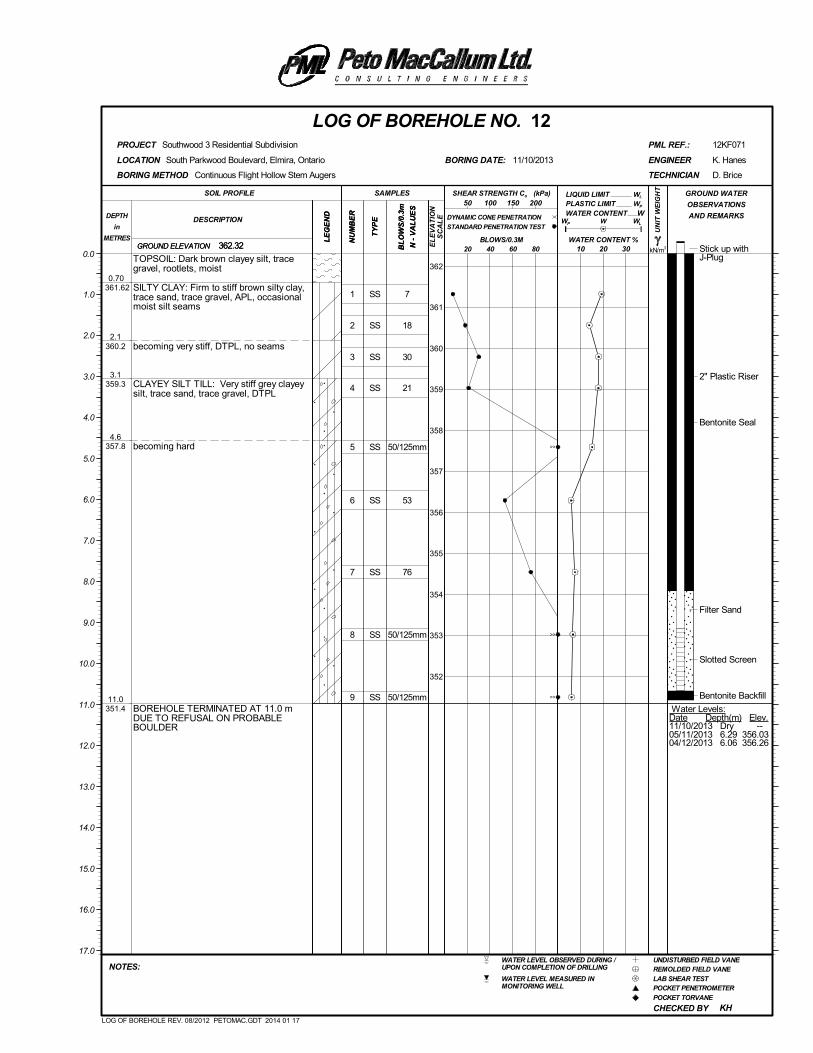
1
2
3
4
5
6
7
8
9
SS
SS
SS
SS
SS
SS
SS
SS
SS
7
18
30
21
50/125mm
53
76
50/125mm
50/125mm
Stick up withJ-Plug
2" Plastic Riser
Bentonite Seal
Filter Sand
Slotted Screen
Bentonite Backfill
Water Levels:Date Depth(m) Elev.11/10/2013 Dry --05/11/2013 6.29 356.0304/12/2013 6.06 356.26
0.70 361.62
2.1360.2
3.1359.3
4.6357.8
11.0351.4
TOPSOIL: Dark brown clayey silt, tracegravel, rootlets, moist
SILTY CLAY: Firm to stiff brown silty clay,trace sand, trace gravel, APL, occasionalmoist silt seams
becoming very stiff, DTPL, no seams
CLAYEY SILT TILL: Very stiff grey clayeysilt, trace sand, trace gravel, DTPL
becoming hard
BOREHOLE TERMINATED AT 11.0 mDUE TO REFUSAL ON PROBABLEBOULDER
(kPa)
kN/m3
UN
IT W
EIG
HT
LE
GE
ND
LIQUID LIMIT
NU
MB
ER
CHECKED BY
GROUND ELEVATION
PLASTIC LIMIT
South Parkwood Boulevard, Elmira, Ontario
WL
LOCATION
Southwood 3 Residential Subdivision
W
D. Brice
362.32
KH
BORING DATE:
REMOLDED FIELD VANEWATER LEVEL OBSERVED DURING /UPON COMPLETION OF DRILLING
POCKET PENETROMETER
POCKET TORVANE
LAB SHEAR TEST
12KF071
UNDISTURBED FIELD VANE
WATER LEVEL MEASURED INMONITORING WELL
PML REF.:
BL
OW
S/0
.3m
N -
VA
LU
ES
LOG OF BOREHOLE NO. 12
10 20 30
NU
MB
ER
SOIL PROFILE
20 40 60 80
TECHNICIAN
DESCRIPTIONDEPTH
in
METRES
NOTES:
K. Hanes
PROJECT
GROUND WATER
OBSERVATIONS
AND REMARKS
LE
GE
ND
SAMPLES
TY
PE WP
WATER CONTENT
50 100 150 200
0.0
362
361
360
359
358
357
356
355
354
353
352
11/10/2013 ENGINEER
1.0
2.0
3.0
4.0
5.0
6.0
7.0
8.0
9.0
10.0
11.0
12.0
13.0
14.0
15.0
16.0
17.0
BLOWS/0.3M
BORING METHOD
WATER CONTENT %362.32
W
WL
Continuous Flight Hollow Stem Augers
GROUND ELEVATION
TY
PE
SHEAR STRENGTH Cu
DYNAMIC CONE PENETRATION
STANDARD PENETRATION TEST
BL
OW
S/0
.3m
N -
VA
LU
ES
EL
EV
AT
ION
SC
AL
E
WP
LOG OF BOREHOLE REV. 08/2012 PETOMAC.GDT 2014 01 17
>>
>>
>>
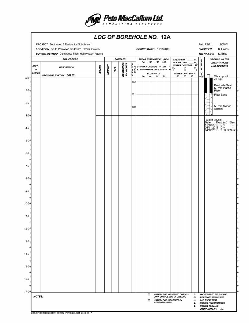
Stick up withJ-Plug
Bentonite Seal50 mm PlasticRiser
Filter Sand
50 mm SlottedScreen
Water Levels:Date Depth(m) Elev.11/10/2013 Dry --05/11/2013 Dry --04/12/2013 2.80 359.52
(kPa)
kN/m3
UN
IT W
EIG
HT
LE
GE
ND
LIQUID LIMIT
NU
MB
ER
CHECKED BY
GROUND ELEVATION
PLASTIC LIMIT
South Parkwood Boulevard, Elmira, Ontario
WL
LOCATION
Southwood 3 Residential Subdivision
W
D. Brice
362.32
KH
BORING DATE:
REMOLDED FIELD VANEWATER LEVEL OBSERVED DURING /UPON COMPLETION OF DRILLING
POCKET PENETROMETER
POCKET TORVANE
LAB SHEAR TEST
12KF071
UNDISTURBED FIELD VANE
WATER LEVEL MEASURED INMONITORING WELL
PML REF.:
BL
OW
S/0
.3m
N -
VA
LU
ES
LOG OF BOREHOLE NO. 12A
10 20 30
NU
MB
ER
SOIL PROFILE
20 40 60 80
TECHNICIAN
DESCRIPTIONDEPTH
in
METRES
NOTES:
K. Hanes
PROJECT
GROUND WATER
OBSERVATIONS
AND REMARKS
LE
GE
ND
SAMPLES
TY
PE WP
WATER CONTENT
50 100 150 200
0.0
362
361
360
11/11/2013 ENGINEER
1.0
2.0
3.0
4.0
5.0
6.0
7.0
8.0
9.0
10.0
11.0
12.0
13.0
14.0
15.0
16.0
17.0
BLOWS/0.3M
BORING METHOD
WATER CONTENT %362.32
W
WL
Continuous Flight Hollow Stem Augers
GROUND ELEVATION
TY
PE
SHEAR STRENGTH Cu
DYNAMIC CONE PENETRATION
STANDARD PENETRATION TEST
BL
OW
S/0
.3m
N -
VA
LU
ES
EL
EV
AT
ION
SC
AL
E
WP
LOG OF BOREHOLE REV. 08/2012 PETOMAC.GDT 2014 01 17
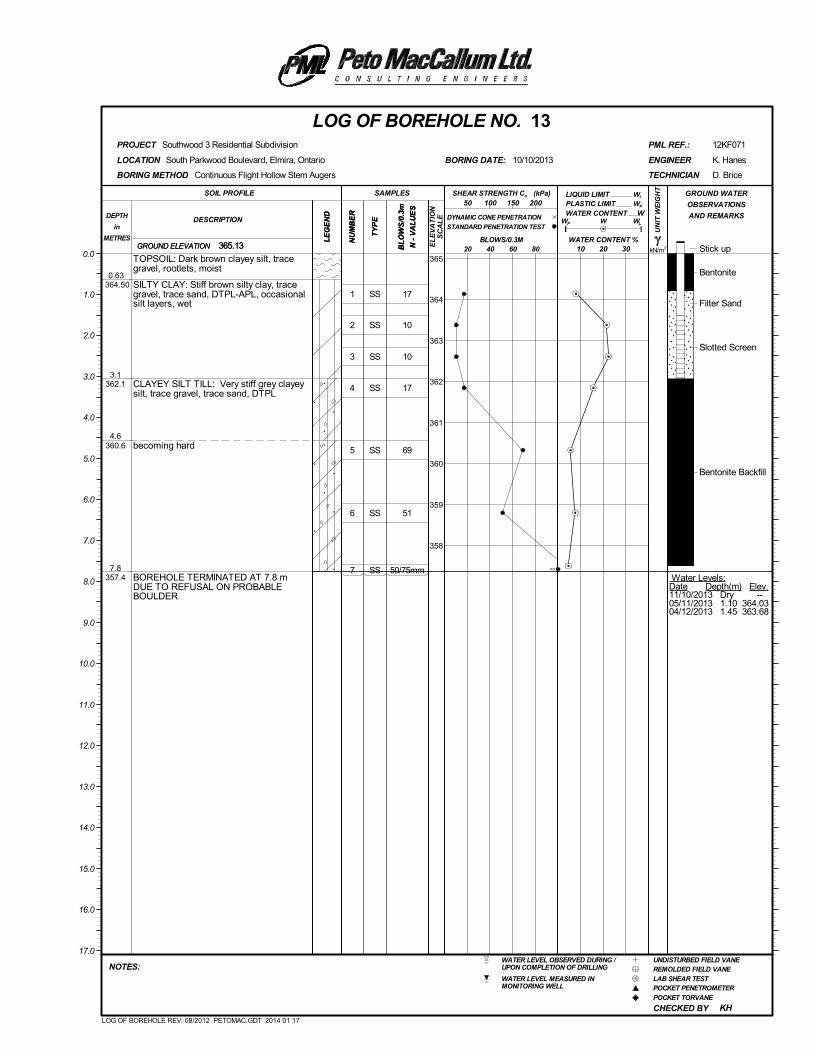
1
2
3
4
5
6
7
SS
SS
SS
SS
SS
SS
SS
17
10
10
17
69
51
50/75mm
Stick up
Bentonite
Filter Sand
Slotted Screen
Bentonite Backfill
Water Levels:Date Depth(m) Elev.11/10/2013 Dry --05/11/2013 1.10 364.0304/12/2013 1.45 363.68
0.63 364.50
3.1362.1
4.6360.6
7.8357.4
TOPSOIL: Dark brown clayey silt, tracegravel, rootlets, moist
SILTY CLAY: Stiff brown silty clay, tracegravel, trace sand, DTPL-APL, occasionalsilt layers, wet
CLAYEY SILT TILL: Very stiff grey clayeysilt, trace gravel, trace sand, DTPL
becoming hard
BOREHOLE TERMINATED AT 7.8 mDUE TO REFUSAL ON PROBABLEBOULDER
(kPa)
kN/m3
UN
IT W
EIG
HT
LE
GE
ND
LIQUID LIMIT
NU
MB
ER
CHECKED BY
GROUND ELEVATION
PLASTIC LIMIT
South Parkwood Boulevard, Elmira, Ontario
WL
LOCATION
Southwood 3 Residential Subdivision
W
D. Brice
365.13
KH
BORING DATE:
REMOLDED FIELD VANEWATER LEVEL OBSERVED DURING /UPON COMPLETION OF DRILLING
POCKET PENETROMETER
POCKET TORVANE
LAB SHEAR TEST
12KF071
UNDISTURBED FIELD VANE
WATER LEVEL MEASURED INMONITORING WELL
PML REF.:
BL
OW
S/0
.3m
N -
VA
LU
ES
LOG OF BOREHOLE NO. 13
10 20 30
NU
MB
ER
SOIL PROFILE
20 40 60 80
TECHNICIAN
DESCRIPTIONDEPTH
in
METRES
NOTES:
K. Hanes
PROJECT
GROUND WATER
OBSERVATIONS
AND REMARKS
LE
GE
ND
SAMPLES
TY
PE WP
WATER CONTENT
50 100 150 200
0.0365
364
363
362
361
360
359
358
10/10/2013 ENGINEER
1.0
2.0
3.0
4.0
5.0
6.0
7.0
8.0
9.0
10.0
11.0
12.0
13.0
14.0
15.0
16.0
17.0
BLOWS/0.3M
BORING METHOD
WATER CONTENT %365.13
W
WL
Continuous Flight Hollow Stem Augers
GROUND ELEVATION
TY
PE
SHEAR STRENGTH Cu
DYNAMIC CONE PENETRATION
STANDARD PENETRATION TEST
BL
OW
S/0
.3m
N -
VA
LU
ES
EL
EV
AT
ION
SC
AL
E
WP
LOG OF BOREHOLE REV. 08/2012 PETOMAC.GDT 2014 01 17
>>
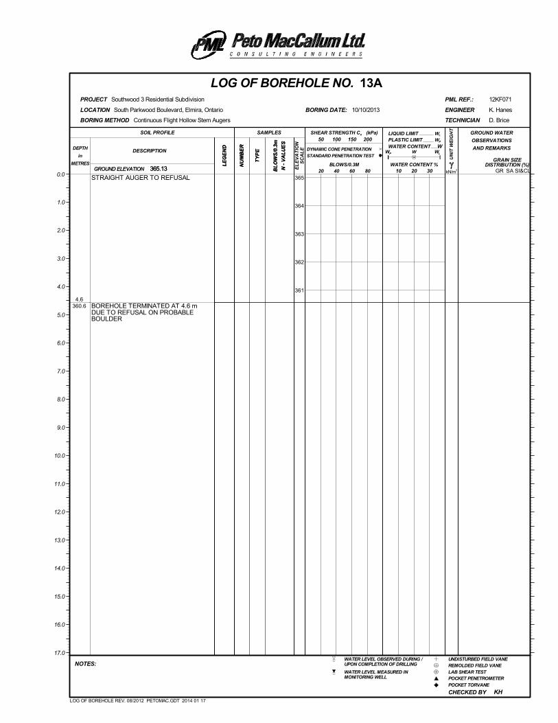
4.6360.6
STRAIGHT AUGER TO REFUSAL
BOREHOLE TERMINATED AT 4.6 mDUE TO REFUSAL ON PROBABLEBOULDER
(kPa)
kN/m3
UN
IT W
EIG
HT
LE
GE
ND
LIQUID LIMIT
NU
MB
ER
CHECKED BY
GRAIN SIZEDISTRIBUTION (%)
GROUND ELEVATION
PLASTIC LIMIT
SA SI&CL
South Parkwood Boulevard, Elmira, Ontario
WL
LOCATION
Southwood 3 Residential Subdivision
W
D. Brice
365.13
KH
BORING DATE:
REMOLDED FIELD VANEWATER LEVEL OBSERVED DURING /UPON COMPLETION OF DRILLING
POCKET PENETROMETER
POCKET TORVANE
LAB SHEAR TEST
12KF071
UNDISTURBED FIELD VANE
WATER LEVEL MEASURED INMONITORING WELL
PML REF.:
BL
OW
S/0
.3m
N -
VA
LU
ES
LOG OF BOREHOLE NO. 13A
10 20 30
NU
MB
ER
SOIL PROFILE
20 40 60 80
TECHNICIAN
DESCRIPTIONDEPTH
in
METRES
NOTES:
K. Hanes
PROJECT
GROUND WATER
OBSERVATIONS
AND REMARKS
LE
GE
ND
SAMPLES
TY
PE WP
WATER CONTENT
50 100 150 200
0.0365
364
363
362
361
10/10/2013 ENGINEER
1.0
2.0
3.0
4.0
5.0
6.0
7.0
8.0
9.0
10.0
11.0
12.0
13.0
14.0
15.0
16.0
17.0
BLOWS/0.3M
BORING METHOD
WATER CONTENT %365.13
W
WL
Continuous Flight Hollow Stem Augers
GROUND ELEVATION
TY
PE
SHEAR STRENGTH Cu
DYNAMIC CONE PENETRATION
STANDARD PENETRATION TEST
BL
OW
S/0
.3m
N -
VA
LU
ES
EL
EV
AT
ION
SC
AL
E
WP
GR
LOG OF BOREHOLE REV. 08/2012 PETOMAC.GDT 2014 01 17
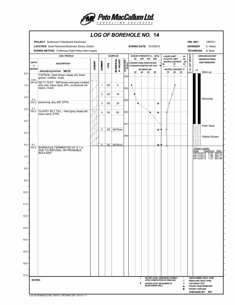
1
2
3
4
5
6
SS
SS
SS
SS
SS
SS
9
18
29
66
50/75mm
50/75mm
Stick up
Bentonite
Filter Sand
Slotted Screen
Water Levels:Date Depth(m) Elev.10/10/2013 5.22 360.0305/11/2013 1.08 364.1704/12/2013 1.37 363.88
0.63 364.62
2.3363.0
3.1362.2
6.1359.2
TOPSOIL: Dark brown clayey silt, tracegravel, rootlets, moist
SILTY CLAY: Stiff brown and grey mottledsilty clay, trace sand, APL, occasional siltlayers, moist
becoming very stiff, DTPL
CLAYEY SILT TILL: Hard grey clayey silt,trace sand, DTPL
BOREHOLE TERMINATED AT 6.1 mDUE TO REFUSAL ON PROBABLEBOULDER
(kPa)
kN/m3
UN
IT W
EIG
HT
LE
GE
ND
LIQUID LIMIT
NU
MB
ER
CHECKED BY
GROUND ELEVATION
PLASTIC LIMIT
South Parkwood Boulevard, Elmira, Ontario
WL
LOCATION
Southwood 3 Residential Subdivision
W
D. Brice
365.25
KH
BORING DATE:
REMOLDED FIELD VANEWATER LEVEL OBSERVED DURING /UPON COMPLETION OF DRILLING
POCKET PENETROMETER
POCKET TORVANE
LAB SHEAR TEST
12KF071
UNDISTURBED FIELD VANE
WATER LEVEL MEASURED INMONITORING WELL
PML REF.:
BL
OW
S/0
.3m
N -
VA
LU
ES
LOG OF BOREHOLE NO. 14
10 20 30
NU
MB
ER
SOIL PROFILE
20 40 60 80
TECHNICIAN
DESCRIPTIONDEPTH
in
METRES
NOTES:
K. Hanes
PROJECT
GROUND WATER
OBSERVATIONS
AND REMARKS
LE
GE
ND
SAMPLES
TY
PE WP
WATER CONTENT
50 100 150 200
0.0365
364
363
362
361
360
10/10/2013 ENGINEER
1.0
2.0
3.0
4.0
5.0
6.0
7.0
8.0
9.0
10.0
11.0
12.0
13.0
14.0
15.0
16.0
17.0
BLOWS/0.3M
BORING METHOD
WATER CONTENT %365.25
W
WL
Continuous Flight Hollow Stem Augers
GROUND ELEVATION
TY
PE
SHEAR STRENGTH Cu
DYNAMIC CONE PENETRATION
STANDARD PENETRATION TEST
BL
OW
S/0
.3m
N -
VA
LU
ES
EL
EV
AT
ION
SC
AL
E
WP
LOG OF BOREHOLE REV. 08/2012 PETOMAC.GDT 2014 01 17
>>
>>
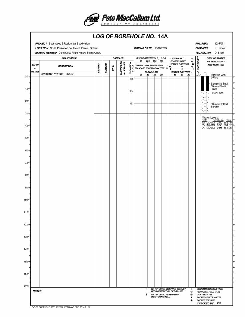
Stick up withJ-Plug
Bentonite Seal50 mm PlasticRiser
Filter Sand
50 mm SlottedScreen
Water Levels:Date Depth(m) Elev.10/10/2013 2.80 362.4005/11/2013 0.53 364.6704/12/2013 0.95 364.25
(kPa)
kN/m3
UN
IT W
EIG
HT
LE
GE
ND
LIQUID LIMIT
NU
MB
ER
CHECKED BY
GROUND ELEVATION
PLASTIC LIMIT
South Parkwood Boulevard, Elmira, Ontario
WL
LOCATION
Southwood 3 Residential Subdivision
W
D. Brice
365.20
KH
BORING DATE:
REMOLDED FIELD VANEWATER LEVEL OBSERVED DURING /UPON COMPLETION OF DRILLING
POCKET PENETROMETER
POCKET TORVANE
LAB SHEAR TEST
12KF071
UNDISTURBED FIELD VANE
WATER LEVEL MEASURED INMONITORING WELL
PML REF.:
BL
OW
S/0
.3m
N -
VA
LU
ES
LOG OF BOREHOLE NO. 14A
10 20 30
NU
MB
ER
SOIL PROFILE
20 40 60 80
TECHNICIAN
DESCRIPTIONDEPTH
in
METRES
NOTES:
K. Hanes
PROJECT
GROUND WATER
OBSERVATIONS
AND REMARKS
LE
GE
ND
SAMPLES
TY
PE WP
WATER CONTENT
50 100 150 200
0.0365
364
363
10/10/2013 ENGINEER
1.0
2.0
3.0
4.0
5.0
6.0
7.0
8.0
9.0
10.0
11.0
12.0
13.0
14.0
15.0
16.0
17.0
BLOWS/0.3M
BORING METHOD
WATER CONTENT %365.20
W
WL
Continuous Flight Hollow Stem Augers
GROUND ELEVATION
TY
PE
SHEAR STRENGTH Cu
DYNAMIC CONE PENETRATION
STANDARD PENETRATION TEST
BL
OW
S/0
.3m
N -
VA
LU
ES
EL
EV
AT
ION
SC
AL
E
WP
LOG OF BOREHOLE REV. 08/2012 PETOMAC.GDT 2014 01 17
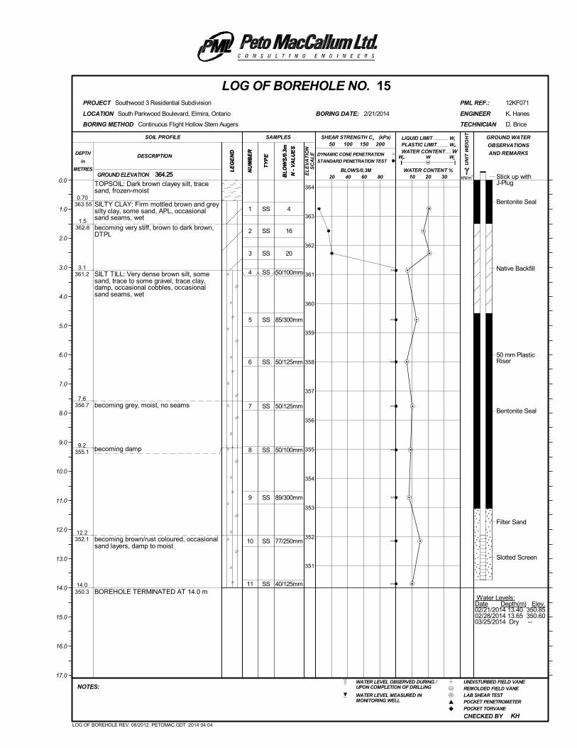
1
2
3
4
5
6
7
8
9
10
11
SS
SS
SS
SS
SS
SS
SS
SS
SS
SS
SS
4
16
20
50/100mm
85/300mm
50/125mm
50/125mm
50/100mm
89/300mm
77/250mm
40/125mm
Stick up withJ-Plug
Bentonite Seal
Native Backfill
50 mm PlasticRiser
Bentonite Seal
Filter Sand
Slotted Screen
Water Levels:Date Depth(m) Elev.02/21/2014 13.40 350.8502/28/2014 13.65 350.6003/25/2014 Dry --
0.70 363.55
1.5362.8
3.1361.2
7.6356.7
9.2355.1
12.2352.1
14.0350.3
TOPSOIL: Dark brown clayey silt, tracesand, frozen-moist
SILTY CLAY: Firm mottled brown and greysilty clay, some sand, APL, occasionalsand seams, wet
becoming very stiff, brown to dark brown,DTPL
SILT TILL: Very dense brown silt, somesand, trace to some gravel, trace clay,damp, occasional cobbles, occasionalsand seams, wet
becoming grey, moist, no seams
becoming damp
becoming brown/rust coloured, occasionalsand layers, damp to moist
BOREHOLE TERMINATED AT 14.0 m
(kPa)
kN/m3
UN
IT W
EIG
HT
LE
GE
ND
LIQUID LIMIT
NU
MB
ER
CHECKED BY
GROUND ELEVATION
PLASTIC LIMIT
South Parkwood Boulevard, Elmira, Ontario
WL
LOCATION
Southwood 3 Residential Subdivision
W
D. Brice
364.25
KH
BORING DATE:
REMOLDED FIELD VANEWATER LEVEL OBSERVED DURING /UPON COMPLETION OF DRILLING
POCKET PENETROMETER
POCKET TORVANE
LAB SHEAR TEST
12KF071
UNDISTURBED FIELD VANE
WATER LEVEL MEASURED INMONITORING WELL
PML REF.:
BL
OW
S/0
.3m
N -
VA
LU
ES
LOG OF BOREHOLE NO. 15
10 20 30
NU
MB
ER
SOIL PROFILE
20 40 60 80
TECHNICIAN
DESCRIPTIONDEPTH
in
METRES
NOTES:
K. Hanes
PROJECT
GROUND WATER
OBSERVATIONS
AND REMARKS
LE
GE
ND
SAMPLES
TY
PE WP
WATER CONTENT
50 100 150 200
0.0364
363
362
361
360
359
358
357
356
355
354
353
352
351
2/21/2014 ENGINEER
1.0
2.0
3.0
4.0
5.0
6.0
7.0
8.0
9.0
10.0
11.0
12.0
13.0
14.0
15.0
16.0
17.0
BLOWS/0.3M
BORING METHOD
WATER CONTENT %364.25
W
WL
Continuous Flight Hollow Stem Augers
GROUND ELEVATION
TY
PE
SHEAR STRENGTH Cu
DYNAMIC CONE PENETRATION
STANDARD PENETRATION TEST
BL
OW
S/0
.3m
N -
VA
LU
ES
EL
EV
AT
ION
SC
AL
E
WP
LOG OF BOREHOLE REV. 08/2012 PETOMAC.GDT 2014 04 04
>>
>>
>>
>>
>>
>>
>>
>>
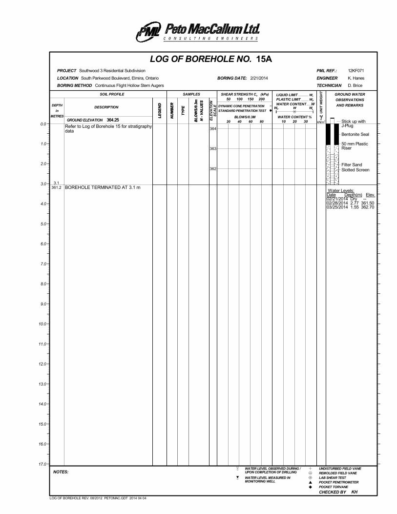
Stick up withJ-Plug
Bentonite Seal
50 mm PlasticRiser
Filter SandSlotted Screen
Water Levels:Date Depth(m) Elev.02/21/2014 Dry --02/28/2014 2.77 361.5003/25/2014 1.55 362.70
3.1361.2
Refer to Log of Borehole 15 for stratigraphydata
BOREHOLE TERMINATED AT 3.1 m
(kPa)
kN/m3
UN
IT W
EIG
HT
LE
GE
ND
LIQUID LIMIT
NU
MB
ER
CHECKED BY
GROUND ELEVATION
PLASTIC LIMIT
South Parkwood Boulevard, Elmira, Ontario
WL
LOCATION
Southwood 3 Residential Subdivision
W
D. Brice
364.25
KH
BORING DATE:
REMOLDED FIELD VANEWATER LEVEL OBSERVED DURING /UPON COMPLETION OF DRILLING
POCKET PENETROMETER
POCKET TORVANE
LAB SHEAR TEST
12KF071
UNDISTURBED FIELD VANE
WATER LEVEL MEASURED INMONITORING WELL
PML REF.:
BL
OW
S/0
.3m
N -
VA
LU
ES
LOG OF BOREHOLE NO. 15A
10 20 30
NU
MB
ER
SOIL PROFILE
20 40 60 80
TECHNICIAN
DESCRIPTIONDEPTH
in
METRES
NOTES:
K. Hanes
PROJECT
GROUND WATER
OBSERVATIONS
AND REMARKS
LE
GE
ND
SAMPLES
TY
PE WP
WATER CONTENT
50 100 150 200
0.0364
363
362
2/21/2014 ENGINEER
1.0
2.0
3.0
4.0
5.0
6.0
7.0
8.0
9.0
10.0
11.0
12.0
13.0
14.0
15.0
16.0
17.0
BLOWS/0.3M
BORING METHOD
WATER CONTENT %364.25
W
WL
Continuous Flight Hollow Stem Augers
GROUND ELEVATION
TY
PE
SHEAR STRENGTH Cu
DYNAMIC CONE PENETRATION
STANDARD PENETRATION TEST
BL
OW
S/0
.3m
N -
VA
LU
ES
EL
EV
AT
ION
SC
AL
E
WP
LOG OF BOREHOLE REV. 08/2012 PETOMAC.GDT 2014 04 04
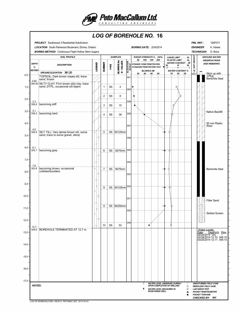
1
2
3
4
5
6
7
8
9
10
SS
SS
SS
SS
SS
SS
SS
SS
SS
SS
4
8
10
39
50/125mm
50/75mm
50/75mm
50/125mm
90/250mm
53
Stick up withJ-PlugBentonite Seal
Native Backfill
50 mm PlasticRiser
Bentonite Seal
Filter Sand
Slotted Screen
Water Levels:Date Depth(m) Elev.02/24/2014 Dry --02/28/2014 12.10 349.1003/25/2014 12.11 349.10
0.60 360.60
2.3358.9
3.1358.2
4.6356.6
6.1355.1
7.6353.6
12.7348.6
TOPSOIL: Dark brown clayey silt, tracesand, frozen
SILTY CLAY: Firm brown silty clay, tracesand, DTPL, occasional silt layers
becoming stiff
becoming hard
SILT TILL: Very dense brown silt, somesand, trace to some gravel, damp
becoming grey
becoming brown, occasionalcobbles/boulders
BOREHOLE TERMINATED AT 12.7 m
(kPa)
kN/m3
UN
IT W
EIG
HT
LE
GE
ND
LIQUID LIMIT
NU
MB
ER
CHECKED BY
GROUND ELEVATION
PLASTIC LIMIT
South Parkwood Boulevard, Elmira, Ontario
WL
LOCATION
Southwood 3 Residential Subdivision
W
D. Brice
361.20
KH
BORING DATE:
REMOLDED FIELD VANEWATER LEVEL OBSERVED DURING /UPON COMPLETION OF DRILLING
POCKET PENETROMETER
POCKET TORVANE
LAB SHEAR TEST
12KF071
UNDISTURBED FIELD VANE
WATER LEVEL MEASURED INMONITORING WELL
PML REF.:
BL
OW
S/0
.3m
N -
VA
LU
ES
LOG OF BOREHOLE NO. 16
10 20 30
NU
MB
ER
SOIL PROFILE
20 40 60 80
TECHNICIAN
DESCRIPTIONDEPTH
in
METRES
NOTES:
K. Hanes
PROJECT
GROUND WATER
OBSERVATIONS
AND REMARKS
LE
GE
ND
SAMPLES
TY
PE WP
WATER CONTENT
50 100 150 200
0.0361
360
359
358
357
356
355
354
353
352
351
350
349
2/24/2014 ENGINEER
1.0
2.0
3.0
4.0
5.0
6.0
7.0
8.0
9.0
10.0
11.0
12.0
13.0
14.0
15.0
16.0
17.0
BLOWS/0.3M
BORING METHOD
WATER CONTENT %361.20
W
WL
Continuous Flight Hollow Stem Augers
GROUND ELEVATION
TY
PE
SHEAR STRENGTH Cu
DYNAMIC CONE PENETRATION
STANDARD PENETRATION TEST
BL
OW
S/0
.3m
N -
VA
LU
ES
EL
EV
AT
ION
SC
AL
E
WP
LOG OF BOREHOLE REV. 08/2012 PETOMAC.GDT 2014 04 04
>>
>>
>>
>>
>>

Stick up withJ-Plug
Bentonite Seal
50 mm PlasticRiser
Filter SandSlotted Screen
Water Levels:Date Depth(m) Elev.02/24/2014 Dry --02/28/2014 3.0 359.2003/25/2014 3.0 359.20
3.1358.2
Refer to Log of Borehole 16 for stratigraphydata
BOREHOLE TERMINATED AT 3.1 m
(kPa)
kN/m3
UN
IT W
EIG
HT
LE
GE
ND
LIQUID LIMIT
NU
MB
ER
CHECKED BY
GROUND ELEVATION
PLASTIC LIMIT
South Parkwood Boulevard, Elmira, Ontario
WL
LOCATION
Southwood 3 Residential Subdivision
W
D. Brice
361.20
KH
BORING DATE:
REMOLDED FIELD VANEWATER LEVEL OBSERVED DURING /UPON COMPLETION OF DRILLING
POCKET PENETROMETER
POCKET TORVANE
LAB SHEAR TEST
12KF071
UNDISTURBED FIELD VANE
WATER LEVEL MEASURED INMONITORING WELL
PML REF.:
BL
OW
S/0
.3m
N -
VA
LU
ES
LOG OF BOREHOLE NO. 16A
10 20 30
NU
MB
ER
SOIL PROFILE
20 40 60 80
TECHNICIAN
DESCRIPTIONDEPTH
in
METRES
NOTES:
K. Hanes
PROJECT
GROUND WATER
OBSERVATIONS
AND REMARKS
LE
GE
ND
SAMPLES
TY
PE WP
WATER CONTENT
50 100 150 200
0.0361
360
359
2/24/2014 ENGINEER
1.0
2.0
3.0
4.0
5.0
6.0
7.0
8.0
9.0
10.0
11.0
12.0
13.0
14.0
15.0
16.0
17.0
BLOWS/0.3M
BORING METHOD
WATER CONTENT %361.20
W
WL
Continuous Flight Hollow Stem Augers
GROUND ELEVATION
TY
PE
SHEAR STRENGTH Cu
DYNAMIC CONE PENETRATION
STANDARD PENETRATION TEST
BL
OW
S/0
.3m
N -
VA
LU
ES
EL
EV
AT
ION
SC
AL
E
WP
LOG OF BOREHOLE REV. 08/2012 PETOMAC.GDT 2014 04 04
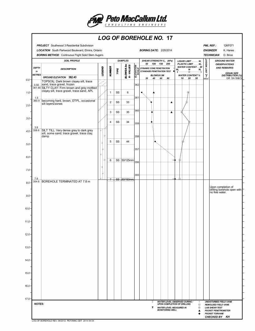
1
2
3
4
5
6
7
SS
SS
SS
SS
SS
SS
SS
6
33
35
34
44
50/125mm
50/150mm
Upon completion ofdrilling borehole open withno free water.
0.50 361.90
1.5360.9
3.8358.6
7.8354.6
TOPSOIL: Dark brown clayey silt, tracesand, trace gravel, frozenSILTY CLAY: Firm brown and grey mottledclayey silt, trace gravel, trace sand, APL
becoming hard, brown, DTPL, occasionalsilt layers/zones
SILT TILL: Very dense grey to dark greysilt, some sand, trace gravel, trace clay,damp
BOREHOLE TERMINATED AT 7.8 m
(kPa)
kN/m3
UN
IT W
EIG
HT
LE
GE
ND
LIQUID LIMIT
NU
MB
ER
CHECKED BY
GRAIN SIZEDISTRIBUTION (%)
GROUND ELEVATION
PLASTIC LIMIT
SA SI&CL
South Parkwood Boulevard, Elmira, Ontario
WL
LOCATION
Southwood 3 Residential Subdivision
W
D. Brice
362.40
KH
BORING DATE:
REMOLDED FIELD VANEWATER LEVEL OBSERVED DURING /UPON COMPLETION OF DRILLING
POCKET PENETROMETER
POCKET TORVANE
LAB SHEAR TEST
12KF071
UNDISTURBED FIELD VANE
WATER LEVEL MEASURED INMONITORING WELL
PML REF.:
BL
OW
S/0
.3m
N -
VA
LU
ES
LOG OF BOREHOLE NO. 17
10 20 30
NU
MB
ER
SOIL PROFILE
20 40 60 80
TECHNICIAN
DESCRIPTIONDEPTH
in
METRES
NOTES:
K. Hanes
PROJECT
GROUND WATER
OBSERVATIONS
AND REMARKS
LE
GE
ND
SAMPLES
TY
PE WP
WATER CONTENT
50 100 150 200
0.0
362
361
360
359
358
357
356
355
2/20/2014 ENGINEER
1.0
2.0
3.0
4.0
5.0
6.0
7.0
8.0
9.0
10.0
11.0
12.0
13.0
14.0
15.0
16.0
17.0
BLOWS/0.3M
BORING METHOD
WATER CONTENT %362.40
W
WL
Continuous Flight Solid Stem Augers
GROUND ELEVATION
TY
PE
SHEAR STRENGTH Cu
DYNAMIC CONE PENETRATION
STANDARD PENETRATION TEST
BL
OW
S/0
.3m
N -
VA
LU
ES
EL
EV
AT
ION
SC
AL
E
WP
GR
LOG OF BOREHOLE REV. 08/2012 PETOMAC.GDT 2014 04 04
>>
>>
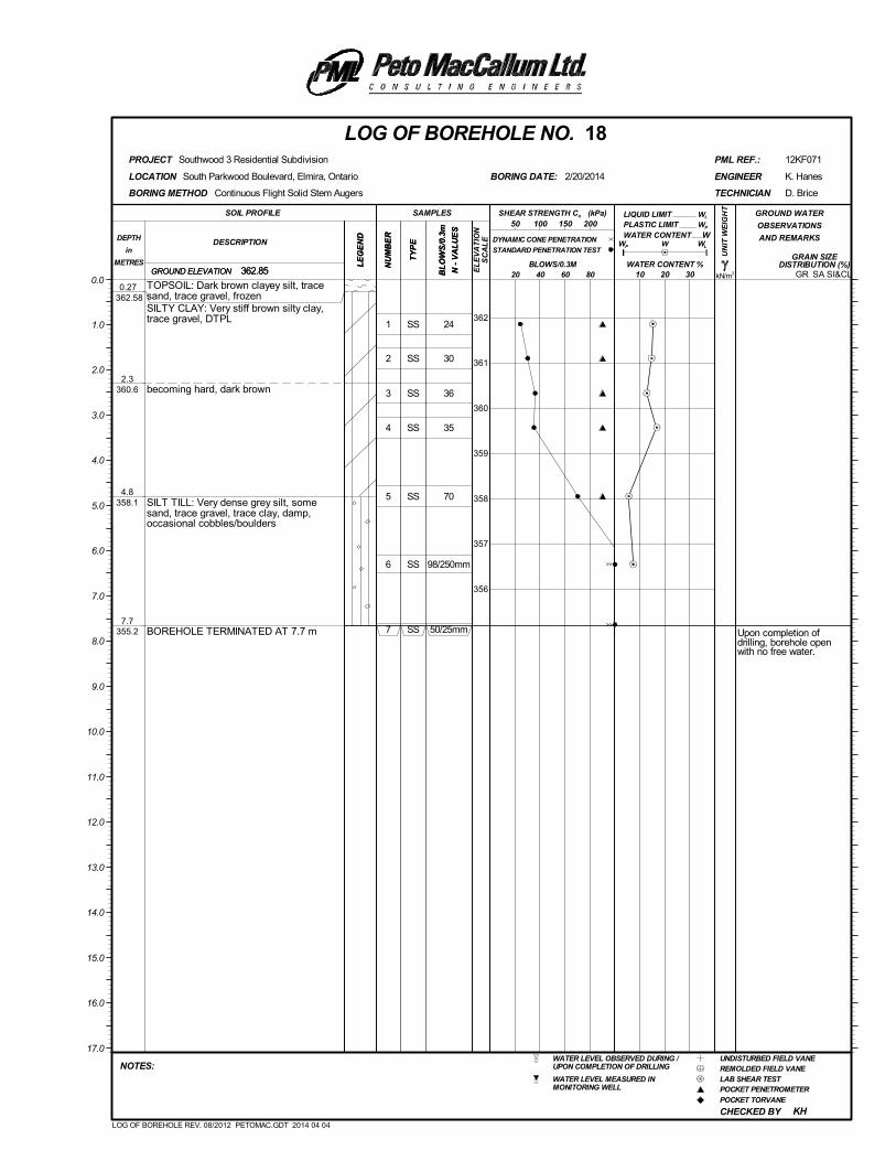
1
2
3
4
5
6
7
SS
SS
SS
SS
SS
SS
SS
24
30
36
35
70
98/250mm
50/25mm Upon completion ofdrilling, borehole openwith no free water.
0.27 362.58
2.3360.6
4.8358.1
7.7355.2
TOPSOIL: Dark brown clayey silt, tracesand, trace gravel, frozenSILTY CLAY: Very stiff brown silty clay,trace gravel, DTPL
becoming hard, dark brown
SILT TILL: Very dense grey silt, somesand, trace gravel, trace clay, damp,occasional cobbles/boulders
BOREHOLE TERMINATED AT 7.7 m
(kPa)
kN/m3
UN
IT W
EIG
HT
LE
GE
ND
LIQUID LIMIT
NU
MB
ER
CHECKED BY
GRAIN SIZEDISTRIBUTION (%)
GROUND ELEVATION
PLASTIC LIMIT
SA SI&CL
South Parkwood Boulevard, Elmira, Ontario
WL
LOCATION
Southwood 3 Residential Subdivision
W
D. Brice
362.85
KH
BORING DATE:
REMOLDED FIELD VANEWATER LEVEL OBSERVED DURING /UPON COMPLETION OF DRILLING
POCKET PENETROMETER
POCKET TORVANE
LAB SHEAR TEST
12KF071
UNDISTURBED FIELD VANE
WATER LEVEL MEASURED INMONITORING WELL
PML REF.:
BL
OW
S/0
.3m
N -
VA
LU
ES
LOG OF BOREHOLE NO. 18
10 20 30
NU
MB
ER
SOIL PROFILE
20 40 60 80
TECHNICIAN
DESCRIPTIONDEPTH
in
METRES
NOTES:
K. Hanes
PROJECT
GROUND WATER
OBSERVATIONS
AND REMARKS
LE
GE
ND
SAMPLES
TY
PE WP
WATER CONTENT
50 100 150 200
0.0
362
361
360
359
358
357
356
2/20/2014 ENGINEER
1.0
2.0
3.0
4.0
5.0
6.0
7.0
8.0
9.0
10.0
11.0
12.0
13.0
14.0
15.0
16.0
17.0
BLOWS/0.3M
BORING METHOD
WATER CONTENT %362.85
W
WL
Continuous Flight Solid Stem Augers
GROUND ELEVATION
TY
PE
SHEAR STRENGTH Cu
DYNAMIC CONE PENETRATION
STANDARD PENETRATION TEST
BL
OW
S/0
.3m
N -
VA
LU
ES
EL
EV
AT
ION
SC
AL
E
WP
GR
LOG OF BOREHOLE REV. 08/2012 PETOMAC.GDT 2014 04 04
>>
>>
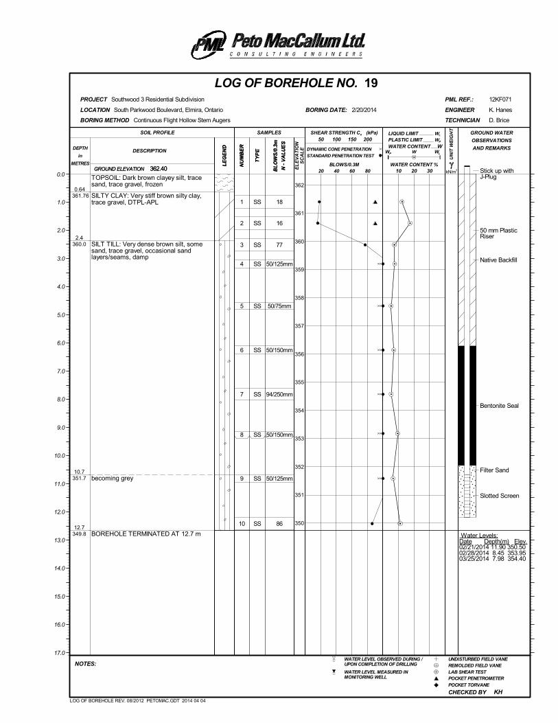
1
2
3
4
5
6
7
8
9
10
SS
SS
SS
SS
SS
SS
SS
SS
SS
SS
18
16
77
50/125mm
50/75mm
50/150mm
94/250mm
50/150mm
50/125mm
86
Stick up withJ-Plug
50 mm PlasticRiser
Native Backfill
Bentonite Seal
Filter Sand
Slotted Screen
Water Levels:Date Depth(m) Elev.02/21/2014 11.90 350.5002/28/2014 8.45 353.9503/25/2014 7.98 354.40
0.64 361.76
2.4360.0
10.7351.7
12.7349.8
TOPSOIL: Dark brown clayey silt, tracesand, trace gravel, frozen
SILTY CLAY: Very stiff brown silty clay,trace gravel, DTPL-APL
SILT TILL: Very dense brown silt, somesand, trace gravel, occasional sandlayers/seams, damp
becoming grey
BOREHOLE TERMINATED AT 12.7 m
(kPa)
kN/m3
UN
IT W
EIG
HT
LE
GE
ND
LIQUID LIMIT
NU
MB
ER
CHECKED BY
GROUND ELEVATION
PLASTIC LIMIT
South Parkwood Boulevard, Elmira, Ontario
WL
LOCATION
Southwood 3 Residential Subdivision
W
D. Brice
362.40
KH
BORING DATE:
REMOLDED FIELD VANEWATER LEVEL OBSERVED DURING /UPON COMPLETION OF DRILLING
POCKET PENETROMETER
POCKET TORVANE
LAB SHEAR TEST
12KF071
UNDISTURBED FIELD VANE
WATER LEVEL MEASURED INMONITORING WELL
PML REF.:
BL
OW
S/0
.3m
N -
VA
LU
ES
LOG OF BOREHOLE NO. 19
10 20 30
NU
MB
ER
SOIL PROFILE
20 40 60 80
TECHNICIAN
DESCRIPTIONDEPTH
in
METRES
NOTES:
K. Hanes
PROJECT
GROUND WATER
OBSERVATIONS
AND REMARKS
LE
GE
ND
SAMPLES
TY
PE WP
WATER CONTENT
50 100 150 200
0.0
362
361
360
359
358
357
356
355
354
353
352
351
350
2/20/2014 ENGINEER
1.0
2.0
3.0
4.0
5.0
6.0
7.0
8.0
9.0
10.0
11.0
12.0
13.0
14.0
15.0
16.0
17.0
BLOWS/0.3M
BORING METHOD
WATER CONTENT %362.40
W
WL
Continuous Flight Hollow Stem Augers
GROUND ELEVATION
TY
PE
SHEAR STRENGTH Cu
DYNAMIC CONE PENETRATION
STANDARD PENETRATION TEST
BL
OW
S/0
.3m
N -
VA
LU
ES
EL
EV
AT
ION
SC
AL
E
WP
LOG OF BOREHOLE REV. 08/2012 PETOMAC.GDT 2014 04 04
>>
>>
>>
>>
>>
>>

Stick up withJ-Plug
Bentonite Seal
50 mm PlasticRiser
Filter SandSlotted Screen
Water Levels:Date Depth(m) Elev.02/21/2014 Dry --02/28/2014 3.05 359.3003/25/2014 3.05 359.30
3.1359.3
Refer to Log of Borehole 19 for stratigraphydata
BOREHOLE TERMINATED AT 3.1 m
(kPa)
kN/m3
UN
IT W
EIG
HT
LE
GE
ND
LIQUID LIMIT
NU
MB
ER
CHECKED BY
GROUND ELEVATION
PLASTIC LIMIT
South Parkwood Boulevard, Elmira, Ontario
WL
LOCATION
Southwood 3 Residential Subdivision
W
D. Brice
362.35
KH
BORING DATE:
REMOLDED FIELD VANEWATER LEVEL OBSERVED DURING /UPON COMPLETION OF DRILLING
POCKET PENETROMETER
POCKET TORVANE
LAB SHEAR TEST
12KF071
UNDISTURBED FIELD VANE
WATER LEVEL MEASURED INMONITORING WELL
PML REF.:
BL
OW
S/0
.3m
N -
VA
LU
ES
LOG OF BOREHOLE NO. 19A
10 20 30
NU
MB
ER
SOIL PROFILE
20 40 60 80
TECHNICIAN
DESCRIPTIONDEPTH
in
METRES
NOTES:
K. Hanes
PROJECT
GROUND WATER
OBSERVATIONS
AND REMARKS
LE
GE
ND
SAMPLES
TY
PE WP
WATER CONTENT
50 100 150 200
0.0
362
361
360
2/21/2014 ENGINEER
1.0
2.0
3.0
4.0
5.0
6.0
7.0
8.0
9.0
10.0
11.0
12.0
13.0
14.0
15.0
16.0
17.0
BLOWS/0.3M
BORING METHOD
WATER CONTENT %362.35
W
WL
Continuous Flight Hollow Stem Augers
GROUND ELEVATION
TY
PE
SHEAR STRENGTH Cu
DYNAMIC CONE PENETRATION
STANDARD PENETRATION TEST
BL
OW
S/0
.3m
N -
VA
LU
ES
EL
EV
AT
ION
SC
AL
E
WP
LOG OF BOREHOLE REV. 08/2012 PETOMAC.GDT 2014 04 04

1
2
3
4
5
6
7
SS
SS
SS
SS
SS
SS
SS
5
14
67
50/25mm
83
50/150mm
50/50mm
Stick up withJ-Plug
Native Backfill
Bentonite Seal
50 mm PlasticRiser
Filter Sand
Slotted Screen
Water Levels:Date Depth(m) Elev.02/19/2014 Dry --02/28/2014 Dry --03/25/2014 Dry --
0.40 359.60
1.6358.5
2.4357.6
7.7352.3
TOPSOIL: Dark brown clayey silt, tracesand, trace gravel, frozenSILTY CLAY: Firm silty clay, trace gravel,APL
becoming stiff, DTPL
SILT TILL: Very dense brown silt, somesand, trace gravel, occasional cobbles,damp
BOREHOLE TERMINATED AT 7.7 m
(kPa)
kN/m3
UN
IT W
EIG
HT
LE
GE
ND
LIQUID LIMIT
NU
MB
ER
CHECKED BY
GROUND ELEVATION
PLASTIC LIMIT
South Parkwood Boulevard, Elmira, Ontario
WL
LOCATION
Southwood 3 Residential Subdivision
W
D. Brice
360.00
KH
BORING DATE:
REMOLDED FIELD VANEWATER LEVEL OBSERVED DURING /UPON COMPLETION OF DRILLING
POCKET PENETROMETER
POCKET TORVANE
LAB SHEAR TEST
12KF071
UNDISTURBED FIELD VANE
WATER LEVEL MEASURED INMONITORING WELL
PML REF.:
BL
OW
S/0
.3m
N -
VA
LU
ES
LOG OF BOREHOLE NO. 20
10 20 30
NU
MB
ER
SOIL PROFILE
20 40 60 80
TECHNICIAN
DESCRIPTIONDEPTH
in
METRES
NOTES:
K. Hanes
PROJECT
GROUND WATER
OBSERVATIONS
AND REMARKS
LE
GE
ND
SAMPLES
TY
PE WP
WATER CONTENT
50 100 150 200
0.0
359
358
357
356
355
354
353
2/19/2014 ENGINEER
1.0
2.0
3.0
4.0
5.0
6.0
7.0
8.0
9.0
10.0
11.0
12.0
13.0
14.0
15.0
16.0
17.0
BLOWS/0.3M
BORING METHOD
WATER CONTENT %360.00
W
WL
Continuous Flight Hollow Stem Augers
GROUND ELEVATION
TY
PE
SHEAR STRENGTH Cu
DYNAMIC CONE PENETRATION
STANDARD PENETRATION TEST
BL
OW
S/0
.3m
N -
VA
LU
ES
EL
EV
AT
ION
SC
AL
E
WP
LOG OF BOREHOLE REV. 08/2012 PETOMAC.GDT 2014 04 04
>>
>>
>>
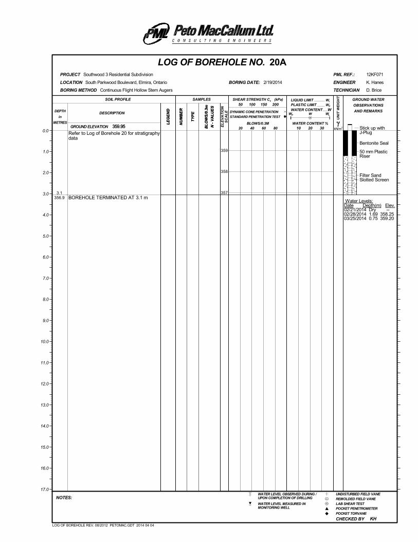
Stick up withJ-Plug
Bentonite Seal
50 mm PlasticRiser
Filter SandSlotted Screen
Water Levels:Date Depth(m) Elev.02/21/2014 Dry --02/28/2014 1.69 358.2503/25/2014 0.75 359.20
3.1356.9
Refer to Log of Borehole 20 for stratigraphydata
BOREHOLE TERMINATED AT 3.1 m
(kPa)
kN/m3
UN
IT W
EIG
HT
LE
GE
ND
LIQUID LIMIT
NU
MB
ER
CHECKED BY
GROUND ELEVATION
PLASTIC LIMIT
South Parkwood Boulevard, Elmira, Ontario
WL
LOCATION
Southwood 3 Residential Subdivision
W
D. Brice
359.95
KH
BORING DATE:
REMOLDED FIELD VANEWATER LEVEL OBSERVED DURING /UPON COMPLETION OF DRILLING
POCKET PENETROMETER
POCKET TORVANE
LAB SHEAR TEST
12KF071
UNDISTURBED FIELD VANE
WATER LEVEL MEASURED INMONITORING WELL
PML REF.:
BL
OW
S/0
.3m
N -
VA
LU
ES
LOG OF BOREHOLE NO. 20A
10 20 30
NU
MB
ER
SOIL PROFILE
20 40 60 80
TECHNICIAN
DESCRIPTIONDEPTH
in
METRES
NOTES:
K. Hanes
PROJECT
GROUND WATER
OBSERVATIONS
AND REMARKS
LE
GE
ND
SAMPLES
TY
PE WP
WATER CONTENT
50 100 150 200
0.0
359
358
357
2/19/2014 ENGINEER
1.0
2.0
3.0
4.0
5.0
6.0
7.0
8.0
9.0
10.0
11.0
12.0
13.0
14.0
15.0
16.0
17.0
BLOWS/0.3M
BORING METHOD
WATER CONTENT %359.95
W
WL
Continuous Flight Hollow Stem Augers
GROUND ELEVATION
TY
PE
SHEAR STRENGTH Cu
DYNAMIC CONE PENETRATION
STANDARD PENETRATION TEST
BL
OW
S/0
.3m
N -
VA
LU
ES
EL
EV
AT
ION
SC
AL
E
WP
LOG OF BOREHOLE REV. 08/2012 PETOMAC.GDT 2014 04 04
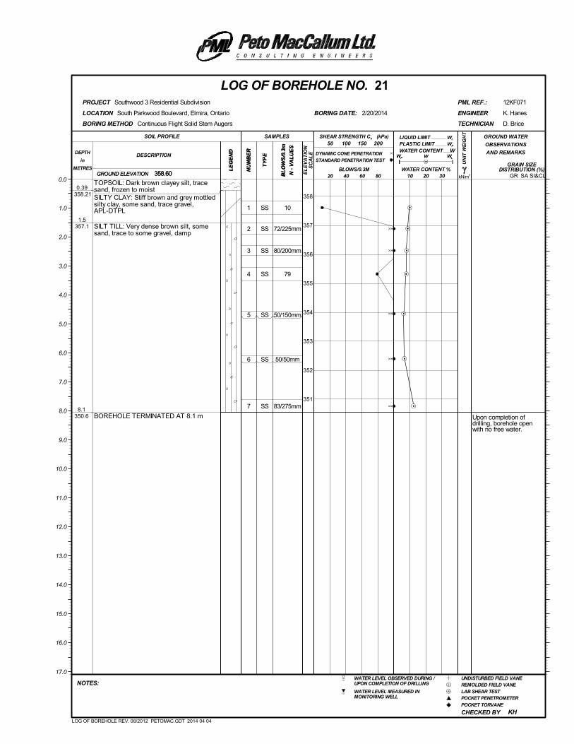
1
2
3
4
5
6
7
SS
SS
SS
SS
SS
SS
SS
10
72/225mm
80/200mm
79
50/150mm
50/50mm
83/275mm
Upon completion ofdrilling, borehole openwith no free water.
0.39 358.21
1.5357.1
8.1350.6
TOPSOIL: Dark brown clayey silt, tracesand, frozen to moistSILTY CLAY: Stiff brown and grey mottledsilty clay, some sand, trace gravel,APL-DTPL
SILT TILL: Very dense brown silt, somesand, trace to some gravel, damp
BOREHOLE TERMINATED AT 8.1 m
(kPa)
kN/m3
UN
IT W
EIG
HT
LE
GE
ND
LIQUID LIMIT
NU
MB
ER
CHECKED BY
GRAIN SIZEDISTRIBUTION (%)
GROUND ELEVATION
PLASTIC LIMIT
SA SI&CL
South Parkwood Boulevard, Elmira, Ontario
WL
LOCATION
Southwood 3 Residential Subdivision
W
D. Brice
358.60
KH
BORING DATE:
REMOLDED FIELD VANEWATER LEVEL OBSERVED DURING /UPON COMPLETION OF DRILLING
POCKET PENETROMETER
POCKET TORVANE
LAB SHEAR TEST
12KF071
UNDISTURBED FIELD VANE
WATER LEVEL MEASURED INMONITORING WELL
PML REF.:
BL
OW
S/0
.3m
N -
VA
LU
ES
LOG OF BOREHOLE NO. 21
10 20 30
NU
MB
ER
SOIL PROFILE
20 40 60 80
TECHNICIAN
DESCRIPTIONDEPTH
in
METRES
NOTES:
K. Hanes
PROJECT
GROUND WATER
OBSERVATIONS
AND REMARKS
LE
GE
ND
SAMPLES
TY
PE WP
WATER CONTENT
50 100 150 200
0.0
358
357
356
355
354
353
352
351
2/20/2014 ENGINEER
1.0
2.0
3.0
4.0
5.0
6.0
7.0
8.0
9.0
10.0
11.0
12.0
13.0
14.0
15.0
16.0
17.0
BLOWS/0.3M
BORING METHOD
WATER CONTENT %358.60
W
WL
Continuous Flight Solid Stem Augers
GROUND ELEVATION
TY
PE
SHEAR STRENGTH Cu
DYNAMIC CONE PENETRATION
STANDARD PENETRATION TEST
BL
OW
S/0
.3m
N -
VA
LU
ES
EL
EV
AT
ION
SC
AL
E
WP
GR
LOG OF BOREHOLE REV. 08/2012 PETOMAC.GDT 2014 04 04
>>
>>
>>
>>
>>
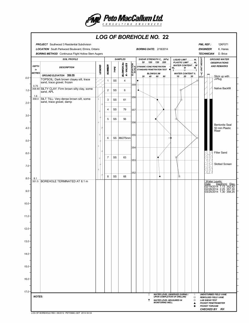
1
2
3
4
5
6
7
8
SS
SS
SS
SS
SS
SS
SS
SS
4
6
61
79
56
88/275mm
63
68
Stick up withJ-Plug
Native Backfill
Bentonite Seal50 mm PlasticRiser
Filter Sand
Slotted Screen
Water Levels:Date Depth(m) Elev.02/19/2014 7.13 352.4202/28/2014 2.25 357.3003/25/2014 1.30 358.25
0.75 358.80
1.6358.0
8.1351.5
TOPSOIL: Dark brown clayey silt, tracesand, trace gravel, frozen
SILTY CLAY: Firm brown silty clay, somesand, APL
SILT TILL: Very dense brown silt, somesand, trace gravel, damp
BOREHOLE TERMINATED AT 8.1 m
(kPa)
kN/m3
UN
IT W
EIG
HT
LE
GE
ND
LIQUID LIMIT
NU
MB
ER
CHECKED BY
GROUND ELEVATION
PLASTIC LIMIT
South Parkwood Boulevard, Elmira, Ontario
WL
LOCATION
Southwood 3 Residential Subdivision
W
D. Brice
359.55
KH
BORING DATE:
REMOLDED FIELD VANEWATER LEVEL OBSERVED DURING /UPON COMPLETION OF DRILLING
POCKET PENETROMETER
POCKET TORVANE
LAB SHEAR TEST
12KF071
UNDISTURBED FIELD VANE
WATER LEVEL MEASURED INMONITORING WELL
PML REF.:
BL
OW
S/0
.3m
N -
VA
LU
ES
LOG OF BOREHOLE NO. 22
10 20 30
NU
MB
ER
SOIL PROFILE
20 40 60 80
TECHNICIAN
DESCRIPTIONDEPTH
in
METRES
NOTES:
K. Hanes
PROJECT
GROUND WATER
OBSERVATIONS
AND REMARKS
LE
GE
ND
SAMPLES
TY
PE WP
WATER CONTENT
50 100 150 200
0.0
359
358
357
356
355
354
353
352
2/18/2014 ENGINEER
1.0
2.0
3.0
4.0
5.0
6.0
7.0
8.0
9.0
10.0
11.0
12.0
13.0
14.0
15.0
16.0
17.0
BLOWS/0.3M
BORING METHOD
WATER CONTENT %359.55
W
WL
Continuous Flight Hollow Stem Augers
GROUND ELEVATION
TY
PE
SHEAR STRENGTH Cu
DYNAMIC CONE PENETRATION
STANDARD PENETRATION TEST
BL
OW
S/0
.3m
N -
VA
LU
ES
EL
EV
AT
ION
SC
AL
E
WP
LOG OF BOREHOLE REV. 08/2012 PETOMAC.GDT 2014 04 04
>>

Stick up withJ-Plug
Bentonite Seal
50 mm PlasticRiser
Filter SandSlotted Screen
Water Levels:Date Depth(m) Elev.02/19/2014 2.65 356.8502/28/2014 1.97 357.5303/25/2014 1.08 358.42
3.1356.5
Refer to Log of Borehole 22 for stratigraphydata
BOREHOLE TERMINATED AT 3.1 m
(kPa)
kN/m3
UN
IT W
EIG
HT
LE
GE
ND
LIQUID LIMIT
NU
MB
ER
CHECKED BY
GROUND ELEVATION
PLASTIC LIMIT
South Parkwood Boulevard, Elmira, Ontario
WL
LOCATION
Southwood 3 Residential Subdivision
W
D. Brice
359.50
KH
BORING DATE:
REMOLDED FIELD VANEWATER LEVEL OBSERVED DURING /UPON COMPLETION OF DRILLING
POCKET PENETROMETER
POCKET TORVANE
LAB SHEAR TEST
12KF071
UNDISTURBED FIELD VANE
WATER LEVEL MEASURED INMONITORING WELL
PML REF.:
BL
OW
S/0
.3m
N -
VA
LU
ES
LOG OF BOREHOLE NO. 22A
10 20 30
NU
MB
ER
SOIL PROFILE
20 40 60 80
TECHNICIAN
DESCRIPTIONDEPTH
in
METRES
NOTES:
K. Hanes
PROJECT
GROUND WATER
OBSERVATIONS
AND REMARKS
LE
GE
ND
SAMPLES
TY
PE WP
WATER CONTENT
50 100 150 200
0.0
359
358
357
2/19/2014 ENGINEER
1.0
2.0
3.0
4.0
5.0
6.0
7.0
8.0
9.0
10.0
11.0
12.0
13.0
14.0
15.0
16.0
17.0
BLOWS/0.3M
BORING METHOD
WATER CONTENT %359.50
W
WL
Continuous Flight Hollow Stem Augers
GROUND ELEVATION
TY
PE
SHEAR STRENGTH Cu
DYNAMIC CONE PENETRATION
STANDARD PENETRATION TEST
BL
OW
S/0
.3m
N -
VA
LU
ES
EL
EV
AT
ION
SC
AL
E
WP
LOG OF BOREHOLE REV. 08/2012 PETOMAC.GDT 2014 04 04
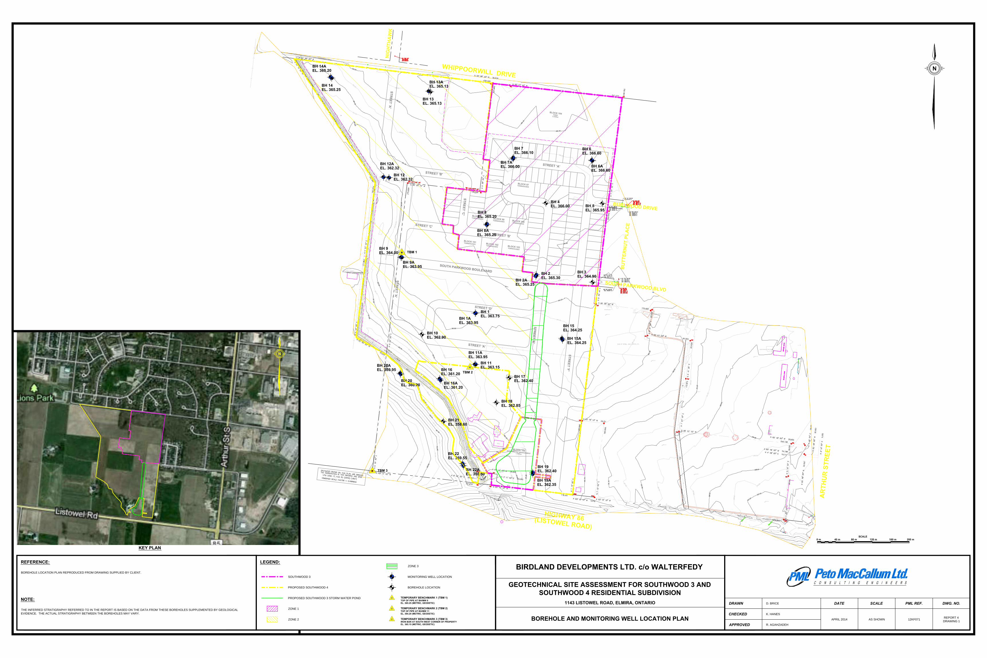
200 m120 m 160 m80 m40 m
SCALE
0 m
SO
UT
H P
AR
KW
O
O
D B
LV
D
B
U
TT
ER
N
U
T P
LA
C
E
BU
RL
W
OO
D D
RIV
E
(L
IS
TO
W
E
L R
O
A
D
)
W
H
IP
PO
O
R
W
IL
L D
R
IV
E
H
IG
H
W
A
Y
86
A
R
TH
U
R
S
TR
EE
T
N
IG
H
TH
A
W
K
L
A
N
E
ST
RE
ET
'A'
ST
RE
ET
'B'
ST
RE
ET
'C
'
TO
W
N
H
O
U
SE
S
B
LO
C
K
98
TO
W
N
H
O
U
SE
S
B
LO
C
K
99
TO
W
N
H
O
U
SE
S
B
LO
C
K
100
TO
W
NH
O
US
ES
BL
O
CK
101
TO
W
N
H
O
U
SE
S
B
LO
C
K
102
TO
W
N
H
O
U
SE
S
BL
O
CK
103
TO
W
N
H
O
U
SE
S
B
LO
C
K
97
PA
RK
B
LO
C
K
104
5.3
54h
a
ST
O
RM
W
AT
ER
M
AN
AG
EM
EN
T
B
LO
C
K
106
1.2
48h
a
ST
RE
ET
'A'
SO
UT
H P
AR
KW
O
O
D B
O
UL
EV
AR
D
ST
RE
ET
'D'
ST
R
EE
T 'C
'
ST
R
EE
T 'B
'
ST
RE
ET
'F
'
ST
RE
ET
'A
'
BH 14
EL. 365.25
BH 14A
EL. 365.20
BH 13A
EL. 365.13
BH 12
EL. 362.32
BH 12A
EL. 362.32
BH 9
EL. 364.00
BH 8
EL. 365.20
BH 1
EL. 363.75
BH 16A
EL. 361.20
BH 20A
EL. 359.95
BH 20
EL. 360.00
BH 22A
EL. 359.50
BH 8A
EL. 365.25
BH 22
EL. 359.55
BH 19
EL. 362.40
BH 19A
EL. 362.35
BH 6A
EL. 366.60
BH 11A
EL. 363.95
BH 16
EL. 361.20
BH 7
EL. 366.10
BH 2A
EL. 365.25
BH 15
EL. 364.25
BH 21
EL. 358.60
BH 15A
EL. 364.25
BH 2
EL. 365.30
BH 3
EL. 364.90
BH 10
EL. 362.90
BH 13
EL. 365.13
BH 18
EL. 362.85
BH 17
EL. 362.40
TBM 3
TBM 2
TBM 1
N
DRAWN
CHECKED
APPROVED
DATE SCALE PML REF. DWG. NO.D. BRICE
K. HANES
R. AGAHZADEH
APRIL 2014 AS SHOWN 12KF071
REPORT 4
DRAWING 1
BIRDLAND DEVELOPMENTS LTD. c/o WALTERFEDY
GEOTECHNICAL SITE ASSESSMENT FOR SOUTHWOOD 3 AND
SOUTHWOOD 4 RESIDENTIAL SUBDIVISION
1143 LISTOWEL ROAD, ELMIRA, ONTARIO
BOREHOLE AND MONITORING WELL LOCATION PLAN
LEGEND:
PROPOSED SOUTHWOOD 4
REFERENCE:
BOREHOLE LOCATION PLAN REPRODUCED FROM DRAWING SUPPLIED BY CLIENT.
NOTE:
THE INFERRED STRATIGRAPHY REFERRED TO IN THE REPORT IS BASED ON THE DATA FROM THESE BOREHOLES SUPPLEMENTED BY GEOLOGICAL
EVIDENCE. THE ACTUAL STRATIGRAPHY BETWEEN THE BOREHOLES MAY VARY.
SOUTHWOOD 3 MONITORING WELL LOCATION
BOREHOLE LOCATION
PROPOSED SOUTHWOOD 3 STORM WATER POND
ZONE 1
ZONE 2
ZONE 3
KEY PLAN
TEMPORARY BENCHMARK 1 (TBM 1)
TOP OF PIPE AT BH/MW 9
EL. 365.25 (METRIC, GEODETIC)
TEMPORARY BENCHMARK 2 (TBM 2)
TOP OF PIPE AT BH/MW 11
EL. 364.20 (METRIC, GEODETIC)
TEMPORARY BENCHMARK 3 (TBM 3)
IRON BAR AT SOUTH WEST CORNER OF PROPERTY
EL. 365.15 (METRIC, GEODETIC)

Geotechnical Investigation, Southwood 3 and Southwood 4 Residential Subdivision PML Ref.: 12KF071, Report: 4 April 25, 2014
APPENDIX A
ENGINEERED FILL
ENGINEERED FILL
Appendix A, Page 1 of 4
Revised 2007-08
The information presented in this appendix is intended for general guidance only. Site specific conditions and prevailing weather may require modification of compaction standards, backfill type or procedures. Each site must be discussed, and procedures agreed with Peto MacCallum Ltd. prior to the start of the earthworks and must be subject to ongoing review during construction. This appendix is not intended to apply to embankments. Steeply sloping ravine residential lots require special consideration.
For fill to be classified as engineered fill suitable for supporting structural loads, a number of conditions must be satisfied, including but not necessarily limited to the following:
1. Purpose
The site specific purpose of the engineered fill must be recognized. In advance of construction, all parties should discuss the project and its requirements and agree on an appropriate set of standards and procedures.
2. Minimum Extent
The engineered fill envelope must extend beyond the footprint of the structure to be supported. The minimum extent of the envelope should be defined from a geotechnical perspective by:
• at founding level, extend a minimum 1.0 m beyond the outer edge of the foundations, greater if adequate layout has not yet been completed as noted below; and
• extend downward and outward at a slope no greater than 45° to meet the subgrade
All fill within the envelope established above must meet the requirements of engineered fill in order to support the structure safely. Other considerations such as survey control, or construction methods may require an envelope that is larger, as noted in the following sections.
Once the minimum envelope has been established, structures must not be moved or extended without consultation with Peto MacCallum Ltd. Similarly, Peto MacCallum Ltd. should be consulted prior to any excavation within the minimum envelope.
3. Survey Control
Accurate survey control is essential to the success of an engineered fill project. The boundaries of the engineered fill must be laid out by a surveyor in consultation with engineering staff from Peto MacCallum Ltd. Careful consideration of the maximum building envelope is required.
During construction it is necessary to have a qualified surveyor provide total station control on the three dimensional extent of filling.
ENGINEERED FILL
Appendix A, Page 2 of 4
Revised 2007-08
4. Subsurface Preparation
Prior to placement of fill, the subgrade must be prepared to the satisfaction of Peto MacCallum Ltd. All deleterious material must be removed and in some cases, excavation of native mineral soils may be required.
Particular attention must be paid to wet subgrades and possible additional measures required to achieve sufficient compaction. Where fill is placed against a slope, benching may be necessary and natural drainage paths must not be blocked.
5. Suitable Fill Materials
All material to be used as fill must be approved by Peto MacCallum Ltd. Such approval will be influenced by many factors and must be site and project specific. External fill sources must be sampled, tested and approved prior to material being hauled to site.
6. Test Section
In advance of the start of construction of the engineered fill pad, the Contractor should conduct a test section. The compaction criterion will be assessed in consultation with Peto MacCallum Ltd. for the various fill material types using different lift thicknesses and number of passes for the compaction equipment proposed by the Contractor.
Additional test sections may be required throughout the course of the project to reflect changes in fill sources, natural moisture content of the material and weather conditions.
The Contractor should be particularly aware of changes in the moisture content of fill material. Site review by Peto MacCallum Ltd. is required to ensure the desired lift thickness is maintained and that each lift is systematically compacted, tested and approved before a subsequent lift is commenced.
7. Inspection and Testing
Uniform, thorough compaction is crucial to the performance of the engineered fill and the supported structure. Hence, all subgrade preparation, filling and compacting must be carried out under the full time inspection by Peto MacCallum Ltd.
All founding surfaces for all buildings and residential dwellings or any part thereof (including but not limited to footings and floor slabs) on structural fill or native soils must be inspected and approved by PML engineering personnel prior to placement of the base/subbase granular material and/or concrete. The purpose of the inspection is to ensure the subgrade soils are capable of supporting the building/house foundation and floor slab loads and to confirm the building/house envelope does not extend beyond the limits of any structural fill pads.
ENGINEERED FILL
Appendix A, Page 3 of 4
Revised 2007-08
8. Protection of Fill
Fill is generally more susceptible to the effects of weather than natural soil. Fill placed and approved to the level at which structural support is required must be protected from excessive wetting, drying, erosion or freezing. Where adequate protection has not been provided, it may be necessary to provide deeper footings or to strip and recompact some of the fill.
9. Construction Delay Time Considerations
The integrity of the fill pad can deteriorate due to the harsh effects of our Canadian weather. Hence, particular care must be taken if the fill pad is constructed over a long time period.
It is necessary therefore, that all fill sources are tested to ensure the material compactability prior to the soil arriving at site. When there has been a lengthy delay between construction periods of the fill pad, it is necessary to conduct subgrade proof rolling, test pits or boreholes to verify the adequacy of the exposed subgrade to accept new fill material.
When the fill pad will be constructed over a lengthy period of time, a field survey should be completed at the end of each construction season to verify the areal extent and the level at which the compacted fill has been brought up to, tested and approved.
In the following spring, subexcavation may be necessary if the fill pad has been softened attributable to ponded surface water or freeze/thaw cycles.
A new survey is required at the beginning of the next construction season to verify that random dumping and/or spreading of fill has not been carried out at the site.
10. Approved Fill Pad Surveillance
It should be appreciated that once the fill pad has been brought to final grade and documented by field survey, there must be ongoing surveillance to ensure that the integrity of the fill pad is not threatened.
Grading operations adjacent to fill pads can often take place several months or years after completion of the fill pad.
It is imperative that all site management and supervision staff, the staff of Contractors and earthwork operators be fully aware of the boundaries of all approved engineered fill pads.
Excavation into an approved engineered fill pad should never be contemplated without the full knowledge, approval and documentation by the geotechnical consultant.
If the fill pad is knowingly built several years in advance of ultimate construction, the areal limits of the fill pad should be substantially overbuilt laterally to allow for changes in possible structure location and elevation and other earthwork operations and competing interests on the site. The overbuilt distance required is project and/or site specified.
ENGINEERED FILL
Appendix A, Page 4 of 4
Revised 2007-08
Iron bars should be placed at the corner/intermediate points of the fill pad as a permanent record of the approved limits of the work for record keeping purposes.
11. Unusual Working Conditions
Construction of fill pads may at times take place at night and/or during periods of freezing weather conditions because of the requirements of the project schedule. It should be appreciated therefore, that both situations present more difficult working conditions. The Owner, Contractor, Design Consultant and Geotechnical Engineer must be willing to work together to revise site construction procedures, enhance field testing and surveillance, and incorporate design modifications as necessary to suit site conditions.
When working at night there must be sufficient artificial light to properly illuminate the fill pad and borrow areas.
Placement of material to form an engineered fill pad during winter and freezing temperatures has its own special conditions that must be addressed. It is imperative that each day prior to placement of new fill, the exposed subgrade must be inspected and any overnight snow or frozen material removed. Particular attention should be given to the borrow source inspection to ensure only nonfrozen fill is brought to the site.
The Contractor must continually assess the work program and have the necessary spreading and compacting equipment to ensure that densification of the fill material takes place in a minimum amount of time. Changes may be required to the spreading methods, lift thickness, and compaction techniques to ensure the desired compaction is achieved uniformly throughout each fill lift.
The Contractor should adequately protect the subgrade at the end of each shift to minimize frost penetration overnight. Since water cannot be added to the fill material to facilitate compaction, it is imperative that densification of the fill be achieved by additional compaction effort and an appropriate reduced lift thickness. Once the fill pad has been completed, it must be properly protected from freezing temperatures and ponding of water during the spring thaw period.
If the pad is unusually thick or if the fill thickness varies dramatically across the width or length of the fill pad, Peto MacCallum Ltd. should be consulted for additional recommendations. In this case, alternative special provisions may be recommended, such as providing a surcharge preload for a limited time or increase the degree of compaction of the fill.