Embed Size (px)
Citation preview
GEOTECHNICAL REPORT
3636 Stone Way and 3651 Interlake Avenue
l f1 Seattle, Washington
1'\ Project No. T -6628
Terra Associates, Inc.
Prepared for:
Mill Creek Residential Trust, LLC Bellevue, Washington
October 31, 2011
TERRA ASSOCIATES, Inc.
Mr. Sean G. Hyatt Managing Director Mill Creek Residential Trust, LLC 3055- 112th Avenue NE, Suite 202 Bellevue, Washington 98004
Subject: Geotechnical Repm1
Consultants in Geotechnical Engineering, Geology and
Environmental Earth Sciences
3636 Stone Way and 3651 Interlake Avenue 3636 Stone Way North Seattle, Washington
Dear Mr. Hyatt:
October 31 , 2011 Project No. T-6628
As requested, we have conducted a geotechnical engineering study for the subject project. The attached report
presents our findings and recommendations for the geotechnical aspects of project design and construction.
Our field exploration indicates the site is generally underlain by five to seven and one-half inches of asphalt
pavement overlying five and one-half to eight feet of medium dense fill material. Below the fill , three to five feet
of medium dense sand with silt overlying dense to very dense silty sand with gravel (gfacial till) was observed .
At Test Boring B-1 very dense sand with gravel (Advance outwash) was observed below the till formation.
Groundwater was observed in all three test borings. Field testing indicates the presence of a shallow unconfined
water table residing in the upper sand unit above the glacial till and a confined groundwater table residing in the
Advance outwash below the till.
In our opinion, the native soils observed at the projected building elevations will be suitable for support of the
structure using conventional spread footing foundations. Groundwater conditions will require both temporary and
pem1anent dewatering systems be installed.
12525 Willows Road, Suite 101, Kirkland, Washington 98034 Phone (425) 821-7777 • Fax (425) 821-4334
Mr. Sean G. Hyatt October 31, 2011
We trust the infom1ation presented in this report is sufficient for your cun·ent needs. If you have any questions or
require additional information, please call.
Sincerely yours, TERRA ASSOClA TES, INC.
Carolyn Schepper, P.E. Project Engineer
Theodore J. Schepper, P.E. Principal
Project No. T -6628 Page No. ii

TABLE OF CONTENTS
Page No.
1.0 Proj ect Description ........... ....................................................................................... ........ I 2.0 Scope of Work .......... ............. ........................................ ................................ .................. I 3.0 Site Conditions ............ .... ... ........... .......................... ..................................... ................... 2
3.1 Surface .... ......................................................... ................................................... 2 3 .2 Subsurface .......................................................................................................... 2 3.3 Ground\vater ..................................... ............ .................................. .................... 2
4.0 Geologic Hazards .............................. ................... ..... ............................................... ....... 3 4 .1 Seis1nic Hazard Area .............. ....................................................................... ..... 3
5.0 Discussion and Recommendations ........................ .......................................................... 4 5.1 General ............................... ......... ... ............. .... ............................................... .... 4 5.2 Excavation, Shoring, Dewatering ...... .............. .. .... ............................................. 5 5.3 Structural Fill ........ ...... ........ .. ............. .. ............. .................................................. 8 5.4 Foundation Support .......... ................................................... ..... .... .. ........ ............ 9 5.5 Slab-on-Grade Floors ..................................... .................................................... 9 5.6 Lower-Level Building Walls ............................................................... .......... ... 10 5.7 Utilities .......................................................... ................................................... 10
6.0 Additional Services .......................... ............................................................................. 10 7.0 Li1nitations ........................................................ ....... ......... ..................... .. ...................... 10
Figures
V icinity Map .................................. ..................................... ............ ... ....... ........................... Figure I Exploration Location Plan ..... .. ................ .......................... .... ........ ............................... ........ Fi!:,'1ll'e 2 Earth Pressure Load ing Diagram ...................... ................................................................... Figure 3 Load/No Load Zone Diagram ............ ..... ..... ...................... ...... ........... .............. ................... Figure 4 Lateral Earth Pressure on Basement Walls .... ........ ..... .......................................... .......... ..... Fi.!:,'1lre 5 Soldier Pile Walt Drainage Detail .......................................................................... .............. Figure 6 Soi l Nail Wall Drainage Detail ....................................................................................... ..... Figure 7
Appendix
Field Exploration and Laboratory Testing .................... ............................................... ..... Appendix A
Geotechnical Report 3636 Stone Way and 3651 Interlake Avenue
3636 Stone Way North Seattle, Washington
1.0 PROJECT DESCRIPTION
The project consists of redeveloping the 3636 Stone Way North parcel with a four-story residential building with
ground floor retail or commercial space. Below-grade structured parking is also planned and would extend one
level below the elevation of Stone Way Nmth. The adjacent 3651 Interlake Avenue parcel will be used as a
staging, lay down and office area during construction. Design drawings were unavailable at the time of this
report. However, based on our previous experience, we would expect structural loading to be moderate with
isolated columns caring loads of 400 to 800 kips and bearing walls caring loads of four to eight kips per foot.
The recommendations in the following sections of this repmi are based on our understanding of the preceding
design features. We should review design drawings as they become available to verify that our recommendations
have been properly interpreted and to supplement them, ifrequired.
2.0 SCOPE OF WORK
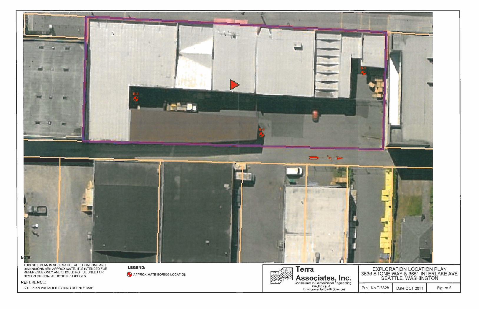
Our work was completed in accordance with our authorized proposal, dated September 14, 2011. On October 4 ,
2011, we subcontracted with Boretec Drilling to advance 3 soil test borings to a maximum depth of 30 feet.
Using soil infonnation obtained from our exploration and laboratory testing, we preformed analyses to develop
geoteclmical reconm1endations for project design and constmction. Specifically, this report addresses the
following:
• Soil and groundwater conditions
• Geologic hazards per City of Seattle Municipal Code
• Seismic design parameters per the current Seattle Building Code
• Excavation, shoring, and dewatering
• Structural fill
• Foundation suppmi
• Slab-on-grade floors
• Lateral earth pressures for below-grade wall design
• Utilities
October 31, 2011 Project No. T-6628
It should be noted that recommendations outlined in this report regarding drainage are associated with soil
strength, design earth pressures, erosion, and stability. Design and performance issues with respect to moisture as
it relates to the structure environment (i.e., humidity, mildew, mold) is beyond Terra Associates· purview. A
building envelope specialist or contractor should be consulted to address these issues, as needed.
3.0 SITE CONDITIONS
3.1 Surface
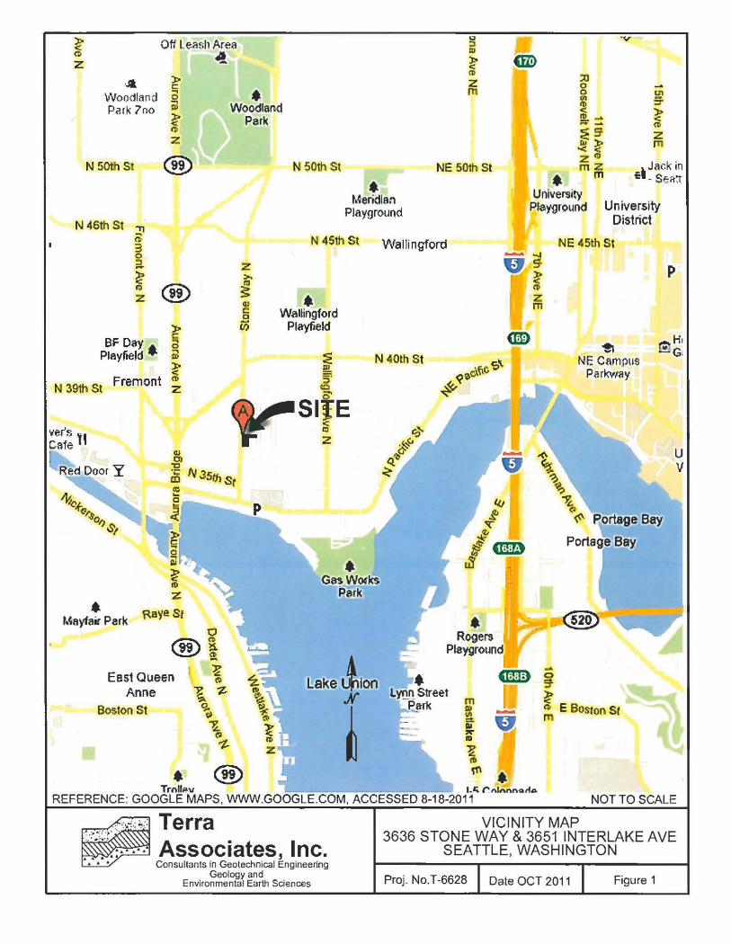
The project site is located at 3636 Stone Way North in Seattle, Washington. The approximate site location is
shown on Figure I.
The 3636 Stone Way North parcel is bordered by retail buildings to the north and south, an alley to the east, and
Stone Way N011h to the east. The parcel is cuiTently occupied by a two-story wood-framed retail building with
parking, storage, and loading areas located on the east side of the structure. The topography of the site is
relatively flat with a gentle slope from east to west and no11h to south.
3.2 Subsurface
Below five to seven and one-half inches of asphalt pavement soil conditions we observed at the test borings
consisted of five and one-half to eight feet of medium dense fill material overlying glacial sediments. At Test
Borings B-1 and B-3 what appears to be dense recessional outwash composed of sand with silt and gravel was
observed below the upper fill to a depth of about ten feet. This layer was not noted in Test Boring B-2. Below
the fill at this boring and underlying the recessional outwash at Test Borings B-1 and B-3, very dense silty sand
with gravel (glacial till) was obseP.'ed to the termination of the test borings. The exception to this was noted at
Test Borit1g B-1 where at a depth of about 28 feet very dense relatively clean sand with gravel, interpreted to be
Advance outwash was encountered.
The Geologic Map of Seattle -- a progress report: U.S. Geological Sun'ey, by K.G . Troost, D.B. Booth, A.P.
Wisher, and S.A. Shimel (2005), maps the site as Qvt (glacial till). Th.is mapped description is consistent with the
most of the native soil conditions we observed in the borings.
The preceding discussion is intended to be a general review of the soil conditions encountered. For more detailed
descriptions, please refer to the Test Boring Logs in Appendix A.
3.3 Groundwatel'
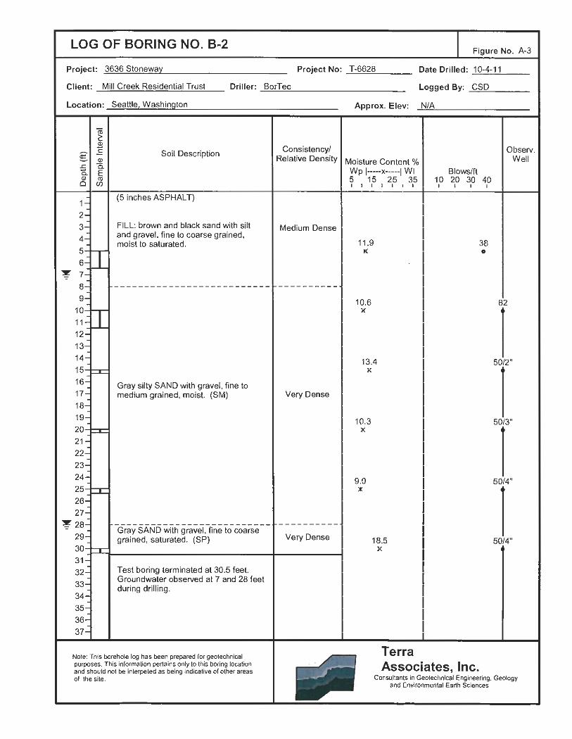
We observed groundwater in all 3 test borings at 6, 7, and 28 feet below cu1rent site grades. The shallow
groundwater observed appears to be an unconfined aquifer residing in the recessional sand layer above the glacial
till. The deeper groundwater is a part of a conftned aquifer residing in the Advance outwash below the glacial till.
Test Borings B-1 and B-3 were converted to observation wells. Test Boring B-l was screened and sealed in the
very dense Advance outwash located below the glacial till. Test Boring B-3 was screened and sealed in the
medium dense sand located above the glacial till.
Page No.2
October 31 , 20 II Project No. T -6628
We returned to tl1e site on October 17,2011 to perfom1 field permeability testing on each of the two wells. The groundwater was observed at a depth of 1.21 feet below cun·ent site grades at Test Boring B-3. At Test Boring B-1, the groundwater was flowing out of the top of the well at a very slow rate. This indicates that the groundwater residing in the Advance outwash below the glacial till is under artesian pressure. No testing was conducted at Test Boring B-1. At Test BoringB-3, we conducted a pump test to detennine the permeability of the sand layer. A two-inch diameter pump was placed in the well and the groundwater was pumped continuously for 60 minutes at a measured rate of 1.8 gallons per minute (gpm). After 60 minutes of pumping the groundwater level in the well was measured at 7.53 feet below cunent site grades. Using a con-elation between pumping rate, well diameter, and drawdown we have estimated the permeability of the upper sand layer to be approximately four to five feet per day.
4.0 GEOLOGIC HAZARDS
4.1 Seismic Hazard Area
Title 25, Chapter 25.09, Section 02 of the Seattle Municipal Code (SMC) defines Seismic Hazard areas as "Areas of the City subject to ground shaking from seismic hazards that are addressed by the Building Code (SMC Title 22). The Seattle Fault zone as delineated in Troost et al., 2005, The Geologic Map of Seattle, a progress report, U.S. Geological Survey, Open-file report 2005-1252 or as the Director detennines is more accurately mapped by the U.S. Geological Survey, as set out in a Director's Rule. For tsunamis, the waterbody of Lake Washington and for tsunamis and tsunami inundation, the water body and land area as shown in Walsh, et al., 2003, Tsunami hazard map of the Elliot Bay area, Seattle, Washington: Modeled tsunami inundation from a Seattle Fault em1hquake, Washington State Department of Natural Resources and National Oceanic and Atmospheric Administration, Washington Division of Geology and Earth Resources Open File Report 2003-14, or as the Director determines are more accurately mapped by the National Oceanic and Atmospheric Administration, the U.S. Geological Survey or the Washington State Department of Natural Resources, as set out in a Director's Rule. The shoreline and upland areas surrounding Lake Washington are classified as an unknown risk from tsunamis under WAC 365-190-080 (4) (b) (iii). For seiches, the waterbodies of Elliot Bay, Lake Union, and Lake Washington. The shoreline and upland areas surrounding the waterbodies in subsection (e) are classified as an unknown risk from seiches under WAC 365-190-080 ( 4) (b) (iii)."
The site is not mapped within any of the above zones and, therefore is not a seismic hazard as defined by the SMC.
Liquefaction is a phenomenon where there is a reduction or complete loss of soil strength due to an increase in water pressure induced by vibrations. Liquefaction mainly affects geologically recent deposits of fine-grained sand that is below the groundwater table. Soils of this nature derive their strength from intergranular friction . The generated water pressure or pore pressure essentially separates the soil grains and eliminates this intergranular friction; thus, eliminating the soil's strength.
Based on the soil and groundwater conditions observed, in our opinion, the potential for soil liquefaction within the upper sand layer observed is negligible. The sand layer is a geologically older fonnation with relative density as indicated by standard penetration ("N") values predominantly in the dense range. These soils would exhibit sufficient shear strength to resist cyclic shear stresses that would be induced by ground shaking during a design level earthquake.
Page No.3
October 3 1 , 20 II Project No. T -6628
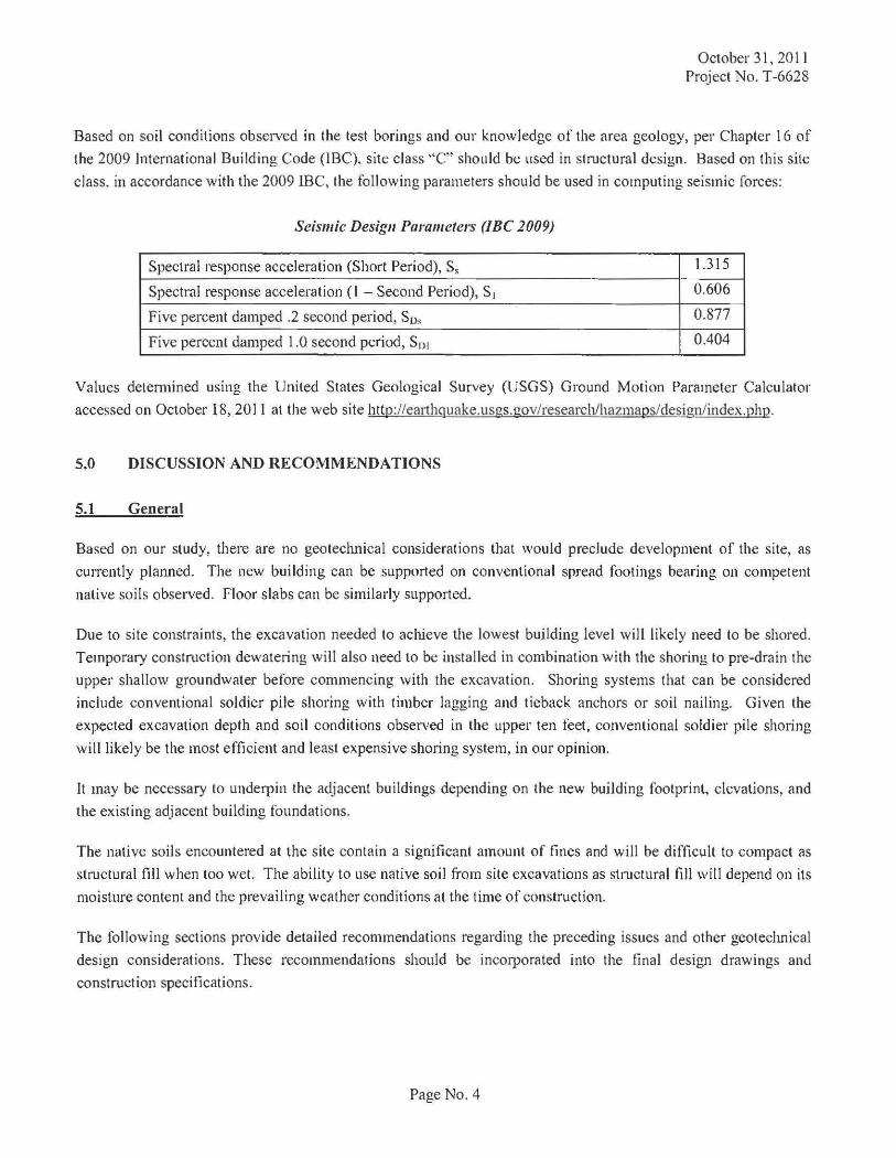
Based on soil conditions observed in the test borings and our knowledge of the area geology, per Chapter 16 of
the 2009 International Building Code (IBC}. site class ''C" should be used in structural design. Based on this site
class, in accordance with the 2009 lBC, the following parameters should be used in computing seismic forces:
Seismic Design Parameters (JBC 2009)
Spectral response acceleration (Short Period), S, 1.315
Spectral response acceleration (I -Second Period), S 1 0.606
Five percent damped .2 second period, S0 , 0.877
Five percent damped 1.0 second period, Sn1 0.404
Values detem1ined using the United States Geological Survey (USGS) Ground Motion Parameter Calculator
accessed on October 18, 2011 at the web site http://earthquake.usgs.gov/research/hazmaps/design/ index.php.
5.0 DISCUSSION AND RECOMMENDATIONS
5.1 General
Based on our study, there are no geotechnical considerations that would preclude development of the site, as
currently pla1med. The new building can be supported on conventional spread footings bearing on competent
native soils observed. Floor slabs can be similarly supported.
Due to site constraints, the excavation needed to achieve the lowest buHding level will likely need to be shored.
Temporary construction dewatering will also need to be installed in combination with the shoring to pre-drain the
upper shallow groundwater before commencing with the excavation. Shoring systems that can be considered
include conventional soldier pile shoring with timber lagging and tieback anchors or soil nailing. Given the
expected excavation depth and soil conditions observed in the upper ten feet, conventional soldier pile shoring
will likely be the most efficient and least expensive shoring system, in our opinion.
It may be necessary to underpin the adjacent buildings depending on the new building footprint, elevations, and
the existing adjacent building foundations.
The native soils encountered at the site contain a significant amount of fines and will be difficult to compact as
structural fill when too wet. The ability to use native soil from site excavations as structural fill will depend on its
moisture content and the prevailing weather conditions at the time of construction.
The following sections provide detailed recommendations regarding the preceding issues and other geoteclmical
design considerations. These recommendations should be incorporated into the final design drawings and
construction specifications.
Page No.4
5.2 Excavation, Shoring, and Dewatering
October 31, 2011 Project No. T-6628
Given the expected excavation depth and building limit s, site constraints will require tJ1at the excavation sidewalls
be supported by temporary shoring. Shoring systems that can be considered include conventional soldier piles
with timber lagging and tieback anchors and soil nailing. Because of the upper fill materials and cleaner sand
layers observed in the test borings, for soil nail shoring to be considered, the use of closely spaced ver1ical
elements extending below the upper ten feet will need to be used to assist in maintaining face stability and
preventing excessive raveling and over-break during excavation.
Tieback anchors or soil nails will extend outside the property lines. Therefore, easements must be obtained from
adjacent property owners and city authorities. Design and constnrction of shoring must also take into
consideration the presence of buried utilities surrounding the property and possibly the presence of below-grade
stntctures on adjacent buildings .
Once the excavation has reached the foundation grade, protection of the bearing subgrade with a layer of rock or
lean mix concrete will need to be considered to prevent disturbance from const ructio n activities.
The following sections outlined our recommendations for design of the temporary shori ng systems.
Soldier Pile Shoring
Soldier pile walls shonld be designed to resist la teral loads imposed by the adjacent soils, building surcharge, and
roadway surcharge loadings that will be imposed. If tieback anchors are used , due to possible utility conflicts,
some of the anchors may need to be inclined at a relatively steep angle. Therefore, the ver1ica l component of the
anchor load should be considered when designing the soldier piles. To support vertical loads, we recommend
soldier piles be designed on the basis of end-bearing and pile shaft friction below the base of the excavation. Pile
shaft friction above the base of the excavation should not be used to resist vet1ical downward loads.
The foll owing soil parameters can be used for design:
• Bearing materials: dense sands
• Allowable end-bearing capacities for soldier piles: 15 kips per square foot (ksf)
• Skin friction below excavation base: 2.0 ksf
We recommend soldier piles have a maximum center-to-center spacing of eight feet. Recommended design earth
pressure diagrams with adjacent traffic surcharge are presented on Figure 3. For pile spacing o f 8 feet and less,
the latera l soil pressure uniformly distributed over the width of the lagging can be reduced by 50 percent to
account for soil arching between the soldier piles.
Unshored excavation heights should not exceed five feet during the excavation. No excavation should remain
unsupported for more than 24 hours.
Page No.5
October 31, 201 I Project No. T-6628
Drilling obstructions, such as boulders, may be encountered. Caving or collapse of opened drilled shafts may also
occur. The contractor must be prepared to case the drilled shafts, as needed, to prevent collapse and maintain a
relatively clean, open hole. If the shafts are relied upon to carry large vertical components of the tieback anchor
loading, the shaft bottoms must be relatively clean of loose soil debris prior to insertion of the soldier piles beam
and pouring concrete.
Over-break or gaps between the excavated soil face and the back of the lagging must be filled following each
excavation lift. Filling with crushed rock or grouting with control density fill (CDF) is recommended. This will
be an important consideration in limiting movement of the adjacent ground.
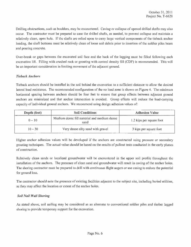
Tieback Anchors
Tieback anchors should be installed in the soil behind the excavation to a sufficient distance to allow the desired
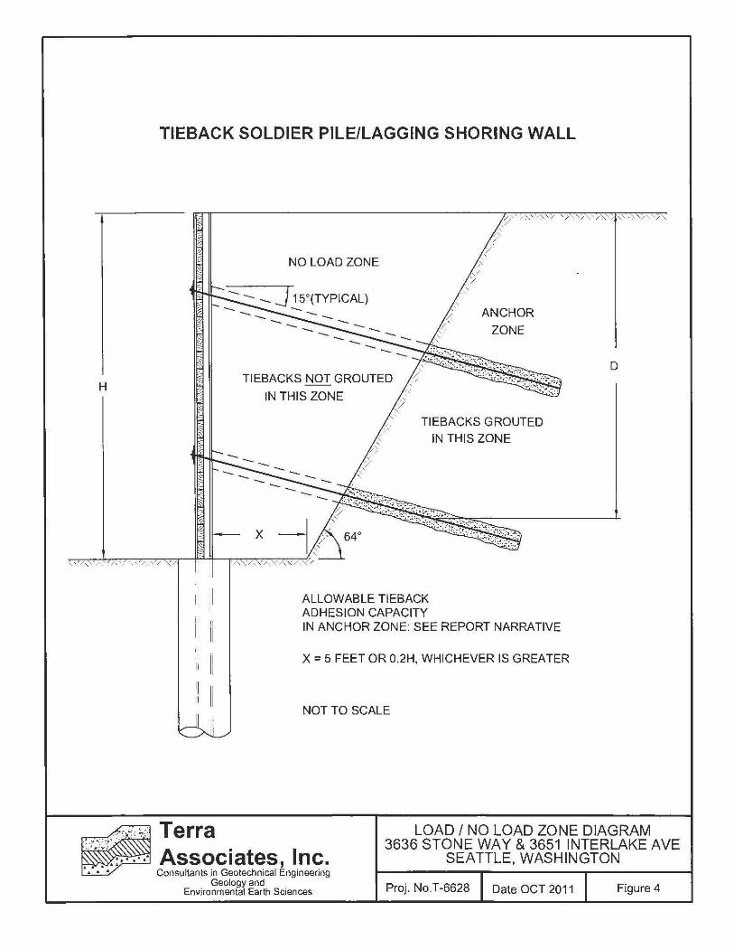
lateral load resi stance. The recommended configuration of the no load zone is shown on Figure 4. The minimum
horizontal spacing between anchors should be four feet to ensure that group effects between adjacent ground
anchors are minimized and that anchor intersection is avoided. Group effects will reduce the load-carrying
capacity of individual ground anchors. We recommend using design adhesion values of:
Depth (feet) Soil Conditions Adhesion Value
0-10 Medium dense fill matetial and medium dense
1.2 kips per square foot sand
10-30 Very dense silty sand with gravel 3 kips per square foot
Higher anchor adhesion values will be developed if the anchors are constmcted using pressure or secondary
grouting techniques. The actual value should be based on the results of pullout tests conducted in the early phases
of constmction.
Relatively clean sands or localized groundwater will be encountered in the upper soil profile throughout the
installation of the anchors. The presence of clean sand and groundwater will result in caving of the anchor holes.
The shoring contractor must be prepared to drill with continuous flight augers or use casing to reduce the potential
for ground loss.
The contractor should note the presence of existing facilities adjacent to the subject site, including buried utilities,
as they may affect the location or extent of the anchor holes.
Soil Nail Wall Shoring
As stated above, soil nailing may be considered as an alternate to conventional soldier piles and timber lagged
shoring to provide temporary support for the excavation.
Page No.6

We reconunend using the following soil parameters for design:
Depth Unit Weight Soil Conditions
(feet) (pcf)
Medium dense fill 3-10 material and medium 120
dense sand
10-30 Dense silty sand with
130 gravel
Soil Friction Cohesion (degrees) (psf)
34 0
40 500
October 31,2011 Project No. T -6628
Nail Adhesion
(ksf)
1.2
3
Higher nail adhesion values will be developed if the soil nails are constructed using pressure or secondary
grouting techniques. The actual value should be based on the results of the pullout tests conducted in the early
phases of construction.
The fill and sand material in the upper ten feet will likely spall or ravel at the excavation face during excavation
and installation of the soil nail anchors. To mitigate this instability and reduce over-break as discussed above, the
use of closely spaced vertical elements and initial flash coating with shotcrete will need to be considered in design
and construction.
Dewateriug
Based on groundwater conditions observed at the test borings, dewatering efforts will need to be implemented in
the upper ten feet of the excavation. Groundwater was observed at 1.2 feet below the cun·ent grade. Field testing
indicates flow rates would be moderate with an average penneability of 4 feet per day indicated by pump testing
of the observation well installed in the south portion of the site (Test Boring B-3). Given the soil conditions, in
our opinion, the most effective dewatering would be accomplished with a system of closely spaced vacuum well
points at the perimeter of the excavation, integrated with the shoring wall construction. The well points would be
spaced evenly between the soldier piles or along the soil nail wall and installed vertically behind the shoring.
U11deJpiuuing
Due to the close proximity of the adjacent buildings to the 3636 Stone Way North parcel, it may become
necessary to underpin the foundations of the buildings depending on their location. Underpinning should be
determined when the building outline and elevations have been established.
1\..fouitoriug Pl'ogram
A monitoring program must be implemented to verify the perfom1ance of the shoring system and possible
excavation effects on adjacent properties. The first step of this program should consist of documenting the
existing conditions of the adjacent properties and pavements. The documentation should include a visual survey
and a pictorial record.
Page No. 7
October 31,2011 Project No. T -6628
We recommend optical sUivey monitoring be conducted by the owner 11nd include the measurement of horizontal
and ver1icalmovements of:
I. The adjacent existing buildings.
2. The surface of the adjacent streets
3. The shoring system
Reference points on existing structures should be placed on the exterior wall, 11djacent to the excavation. The
ex11ct location may be dictated by critical points within the existing structure, such as bearing walls or columns.
To monitor potential vertical and horizontal movements of the shoring, monitoring points should be established at
the top of every other soldier pile or at the top of the soil nails walls with monitoring points spaced no more than
25 feet on center along the soil nail wall length. Surface reference points should also be established and
monitored for elevation and horizontal movement at distances of 5 and I 0 feet from the back of the shoring at
spacing of 25 feet at the excavation perimeter.
Optical monitoring of the shoring system should be performed twice a week as the excavation proceeds and then
once a week upon completion of the exc11vation. A registered land surveyor should be retained to perfonn the
monitoring. Monitoring should continue until the basement walls are adequately braced at the ground surface
level. The monitoring data should be submitted within one day to the project shoring designer and Terra
Associates for review.
5.3 Structural Fill
The native soils encountered at the site contain a sufficient amount of fines that will make them difficult to
compact as structural fill when too wet or too dry. The ability to use native soil fi·om site excavations as structural
fill will depend on its moisture content and the prevailing weather conditions at the time of construction.
If grading activities are planned during the wet winter months, or if they are initiated during the summer and
extend into fall and winter, the owner should be prepared to import wet weather structural fill. For this purpose,
we recommend importing a granular soil that meets the following grading requirements:
U.S. Sieve Size Percent Passi~g 6 inches 100
No.4 75 maximum
No. 200 5 maximum*
* Based on the 3/4-inch fraction.
Prior to use, Ten·a Associates, Inc. should examine and test all materials imported to the site for use as structural
fill.
Structural fill should be placed in uniform loose layers not exceeding 12 inches and compacted to a minimum of
95 percent of the soil' s maximum dry density, as determined by American Society for Testing and Materials
(ASTM) Test Designation D-698 (Standard Proctor). The moisture content of the soil at the time of compaction
should be within minus one to plus three percent of its optimul)l, as determined by this ASTM standard. In
nonstructural areas, the degree of compaction can be reduced to 90 percent.
Page No.8
5.4 Foundation Support
October 31, 20 I l Project No. T-6628
The buildings may be supported on conventional isolated or continuous spread footing foundations bearing on
competent native soils. With one level of below-grade construction, soil conditions providing support should
consist of very dense till. Foundations supported on undisturbed till subgrade can be dimensioned for a net
allowable bearing capacity of 12 ksf. For short-tenn loads, such as wind and seismic, a one-third increase in this allowable capacity can be used. With the anticipated building loads and this bearing stress applied to the soil, we
estimate total foundation settlement would not exceed one-half inch.
For designing foundations to resist lateral loads, a base friction coefficient of 0.35 can be used. Passive earth
pressures acting on the side of the footing can also be considered. We recommend calculating this lateral
resistance using an equivalent fluid weight of 350 pounds per cubic foot (pcf). We recommend not including the
upper 12 inches of soH in this computation because it can be affected by weather or disturbed by future grading
activity. This value assumes the foundation will be constructed neat against competent native soil or backfilled
with structural fill as described in Section 5.3 of this report. The values recommended include a safety factor of
1.5.
5.5 Slab-On-Grade Floors
Slab-on-grade floors may be supported on competent, undisturbed, bearing surfaces consisting of the native silly
sand with gravel. Immediately below the floor slab, we recommend placing a four-inch thick capillary break
layer composed of clean, coarse sand, or fine gravel that has less than three percent passing the No. 200 sieve.
This material will reduce the potential for upward capillary movement of water through the underlying soil and subsequent wetting of the floor slab.
The capillary break layer will not prevent moisture intrusion through the slab caused by water vapor transmission.
Where moisture by vapor transmission is undesirable, such as covered floor areas, a common practice is to place a
durable plastic membrane 10 to 12 mils thick on the capillary break layer and then cover the membrane with a
layer of clean sand or fine gravel to protect it from damage during construction, and to aid in unifonn curing of
the concrete slab. It should be noted that if the sand or gravel layer overlying the membrane is saturated prior to pouring the slab, it will not be effective in assisting unifom1 curing of the slab and can actually serve as a water
supply for moisture bleeding through the slab, potentially affecting floor coverings. Therefore, in our opinion, covering the membrane with a layer of sand or gravel should be avoided if floor slab constmction occurs during
the wet winter months and the layer cannot be effectively drained. We recommend floor designers and contractors refer to the 2003 American Concrete Institute (ACI) Manual of Concrete Practice, Part 2, 302.1 R-96,
for further infonnation regarding vapor barrier installation below slab-on-grade floors.
In addition to the capillary break layer, long-tem1 control of the groundwater below the floor slab using a sub floor
drainage system may be required. This will be dependent on whether the groundwater in the upper outwash layer is entirely intercepted by the perimeter building wall drainage system. The need for a subfloor drainage system
should be detennined by observation of the excavation during construction. If required, the subfloor drainage system would consist of a series of four-inch diameter perforated PVC pipes installed in trenches below the floor
slab. The trenches should be a minimum of 12 inches wide with perforated pipe inverts at 16 inches below the
bottom of floor slab. The trenches/perforated pipes should be backfilled with clean ~-to l-inch washed drainage
aggregate. The perforated pipe network can be laid to grade with trench spacing not exceeding 15 feet. The
perforated pipes should be connected to a header pipe with discharge taken to a sump for collection and discharge
to the stom1 system.
Page No.9
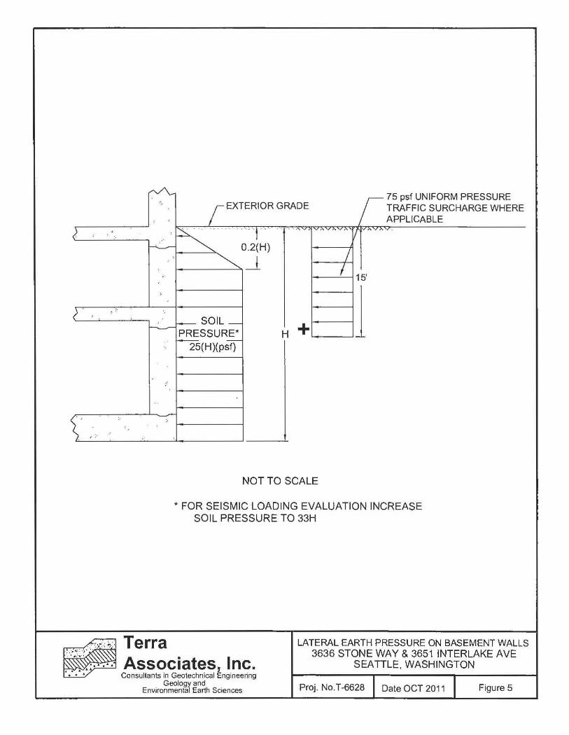
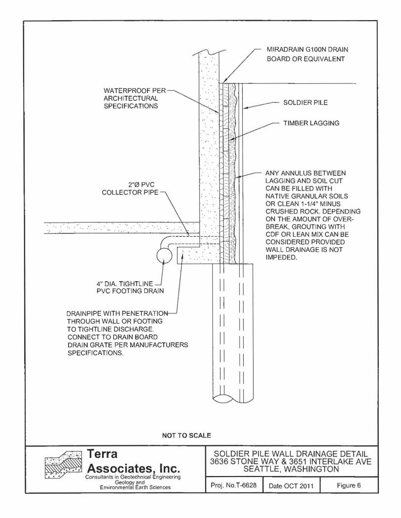
5.6 Lower-Level Building Walls
October 31, 2011 Project No. T -6628
Lower-level building walls should be designed for earth pressure parameters presented on Figure 5. The walls
should also be provided with adequate drainage and waterproofed. Typically, for walls constmcted using
temporary soldier pile/timber lagging, wall drainage is provided by attaching prefabricated drainage panels, such
as Miradrain G I OON, to the shoring. Drainpipes are attached to the Miradrain panels at the wall base and
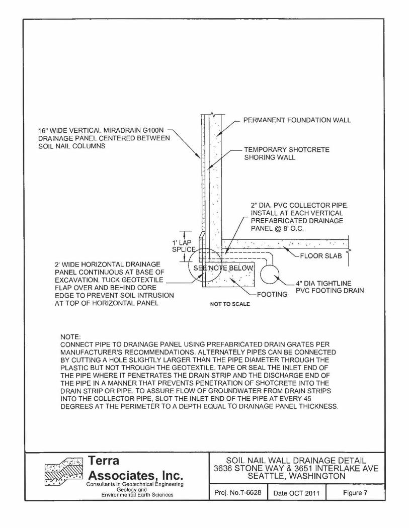
tightlined to discharge through the permanent wall. For soil nail shoring, the drainage panels are installed on the
excavation face, between the soil nails, and then covered with the shotcrete wall facing. A typicnl drainage detail
for pennanent lower-level walls constructed ngainst a soldier pile shoring system is shown on Figure 6. For a soil
nail system see Figure 7.
In addition to the drainage panels, if moisture transmission through the basement walls is not desired, the walls
should be waterproofed by installation of volclay panels or similar materials. A building envelope specialist
should be consulted to design the lower building grade waterproofing if moisture intrusion through the walls is
not considered acceptable.
Total estimated groundwater flow cnptured by the perimete r wall drainage and subfloor drainage system if
installed falls in the range of 35 gpm to 50 gpm.
5.7 Utilities
Utility pipes should be bedded and backfilled in accordance with American Public Works Association (APW A),
or City of Seattle specifications. As a minimum, trench backfill should be placed and compacted as structural fill, as described in Section 5.3 of this report . Most native soils excavated on the site should be suitable for use as
backfill material during dry weather conditions. However, if utility constmction takes place during the wet winter
months, it will likely be necessary to import suitable wet weather fill for utility trench backfilling.
6.0 ADDJTJONAL SERVICES
TeiTa Associates, Inc. should review the final design drawings and specifications in order to verify that earthwork
and foundation recommendations have been properly interpreted and implemented in project design. We should
also provide geotechnical service during constmction to observe compliance with our design concepts,
specifications, and recommendations. This will allow for design changes if subsurface conditions differ from
those anticipated ptior to the start of construction.
7.0 LIMITATJONS
We prepared this report in accordance with generally accepted geotechnical engineering practices. No other
warranty, expressed or implied, is made. This report is the copyrighted property of Terra Associates, lnc. and is
intended for specific application to the 3636 Stone Way and 3651 Interlake Avenue project. This report is for the
exclusive use of Mill Creek Residential Trust, LLC and their authorized representatives.
Page No . 10

October 31, 20 11 Project No. T-6628
The analyses and recommend<ltions present in this repo1t Me based on d<lta obtained from the borings done on
site. Variations in soil conditions can occur, the nature and extent of which may not become evident until construction. If variations appear evident, Ten·a Associates, Inc. should be requested to reevaluate the
recommendations in this report prior to proceeding with construction.
Page No. II
Off I eash Area
.a ~ Woodland o Park 7oo ;
~ ~
z
4
• Woodland Park
I I
I N 50th Sl N 501h St NE 501h St dJack in
- Sert:t
I • MeridiAn Playground
• University PlaY9round University
District ' N 46th St , Q N 4S1h St Wallingford - NE 45th St 3 a ~ Ill
z ®
~ BF Day o Playlield • ~
N 39'1h St Fremont
... ~r's n Cafe
• Mayfair Park
~ z
0
® ~ Ees1Queen
Anne ,__ Bo'3otonSt
•®
I • Wallingford
Playfield
N 40th St
• Gas.WOf~ Park
Lake~ion .K
~
~ ~
~ ~
-v
...
~Ht ~ e:G;
NE Campus ParkYMy
Portage Bay
Portage Bay
~ ~ Q E Boston Sr
"'
T rniiP.v 1-1;. r.l\lnnna rlA REFERENCE: GOOGLE MAPS, WWW.GOOGLE.COM, ACCESSED 8-18-2011 NOT TO SCALE
· ~ ,: .. -: .: ~.:: Terra ... ~:.~:;·~:··· ... · Associates, Inc. • • • Consultants in Geotechnical Engineeling
Geology and Environmental Earth Sciences
VICINITY MAP 3636 STONE WAY & 36511NTERLAKEAVE
SEATTLE, WASHINGTON
Proj. No.T-6628 Date OCT 2011 Figure 1
THIS SITE PLAN IS SCHEMATIC. ALL LOCATIONS AND DIMENSIONS ARE APPROXIMATE. IT IS INTENDED FOR REFERENCE ONLY AND SHOULD NOT BE USED FOR DESIGN OR CONSTRUCTION PURPOSES.
REFERENCE: SITE PLAN PROVIDED BY KING COUNTY I MAP
LEGEND:
s APPROXIMATE BORING LOCATION
Associates Inc. Consultants in Geotechnical ~ngineering
Geology and Environmental Earth Sciences
EXPLORATION LOCATION PLAN 3636 STONE WAY & 3651 INTERLAKE AVE
SEATTLE, WASHINGTON
Proj. No.T-6628 Date OCT 2011 Figure 2
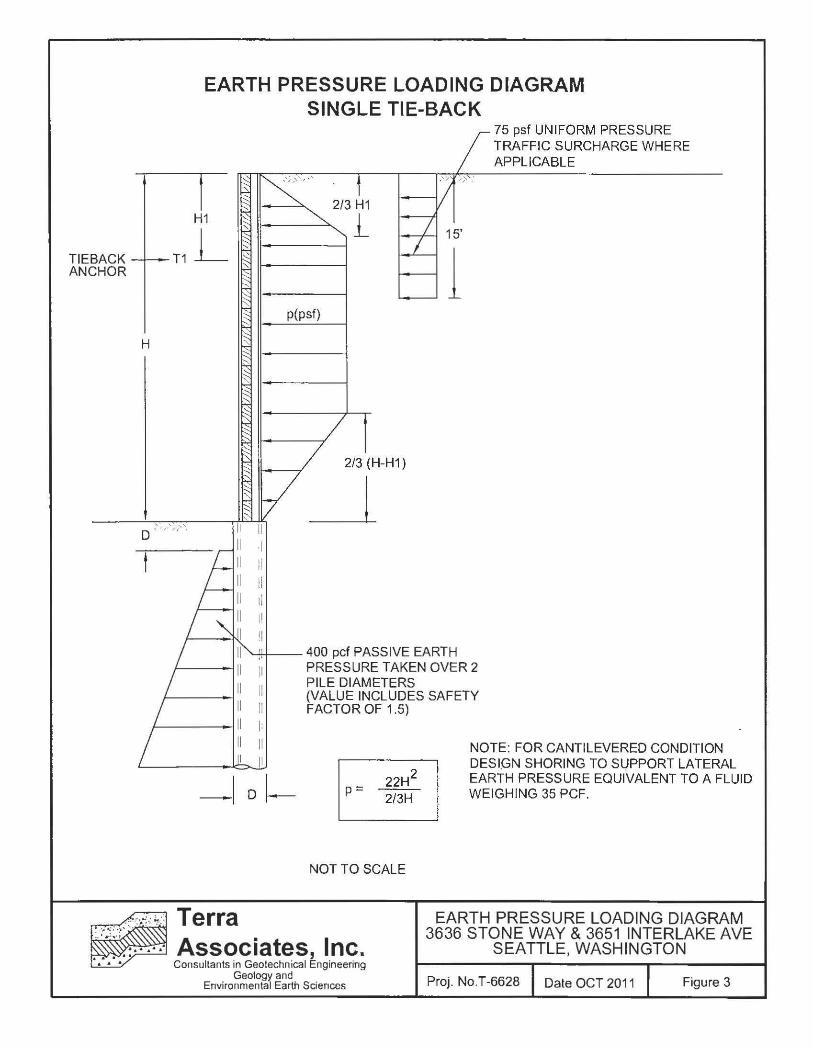
TIEBACK ANCHOR
H
EARTH PRESSURE LOADING DIAGRAM SINGLE TIE-BACK
75 psf UNIFORM PRESSURE TRAFFIC SURCHARGE WHERE APPLICABLE
p(psf)
:1 H II
II
!I
2/3 (H-H1)
_j
'--.*': --400 pcf PASSIVE EARTH
II II II 1:
I II
-1 D~
PRESSURETAKENOVER2 PILE DIAMETERS (VALUE INCLUDES SAFETY FACTOR OF 1.5)
p= 22H2
2/3H
NOT TO SCALE
NOTE: FOR CANTILEVERED CONDITION DESIGN SHORING TO SUPPORT LATERAL EARTH PRESSURE EQUIVALENT TO A FLUID WEIGHING 35 PCF.
-:· ': .. ~-: ~-:: Terra EARTH PRESSURE LOADING DIAGRAM 3636 STONE WAY & 3651 INTERLAKE AVE
SEATTLE, WASHINGTON .·~·~: .-; ::··· .... Associates, Inc. • • • Consultants in Geotechnical Engineering
Geology and Environmental Earth Sdences Proj. No.T-6628 Date OCT 201 1 Figure 3
H
-"""'""""
TIEBACK SOLDIER PILE/LAGGING SHORING WALL
NO LOAD ZONE
- - - j 15°(TYPICAL) - -
TIEBACKS NOT GROUTED
IN THIS ZONE
ANCHOR
ZONE
,i TIEBACKS GROUTED
ALLOWABLE TIEBACK ADHESION CAPACITY
IN THIS ZONE
IN ANCHOR ZONE: SEE REPORT NARRATIVE
X = 5 FEET OR 0.2H, WHICHEVER IS GREATER
NOT TO SCALE
D
Terra Associates, Inc.
LOAD I NO LOAD ZONE DIAGRAM 3636 STONE WAY & 3651 INTERLAKE AVE
SEATTLE, WASHINGTON Consultants in Geotechnical Engineering
Geology and Envi ronmental Earth Sciences Proj . No.T -6628 Date OCT 2011 Figure 4
( . ; ' :
( ' .
\' ,. '
'. ·' '
~ 75 psf UNIFORM PRESSURE ::,
' '
-
.. :
-' ;
- ~~
..
>
r EXTERIOR GRADE TRAFFIC SURCHARGE WHERE APPLICABLE
'~---- ""!" " "'· v •,v· v , l ''v;..v .
0.2(H} j , . ~ -~ I 15'
l _SOIL_ + PRESSURE* H 2s(H}(psf}
'
NOT TO SCALE
*FOR SEISMIC LOADING EVALUATION INCREASE SOIL PRESSURE TO 33H
.. ,: .. :, ~ : : Terra ·· ·:-.\.r . Associates, Inc.
LATERAL EARTH PRESSURE ON BASEMENT WALLS 3636 STONE WAY & 3651 INTERLAKE AVE
SEATTLE, WASHINGTON Consultants in Geotechnical Engineering
Geology and Environmental Earth Sciences Proj. No.T-6628 Date OCT 2011 Figure 5
WATERPROOF PER ARCHITECTURAL SPECIFICATIONS
2"0 PVC COLLECTOR PIPE
. . . ~ . . .
4" DIA. TIGHTLINE PVC FOOTING DRAIN
DRAINPIPE WITH PENETRA TIO THROUGH WALL OR FOOTING TO TIGHTLINE DISCHARGE. CONNECT TO DRAIN BOARD DRAIN GRATE PER MANUFACTURERS SPECIFICATIONS.
. ...
r ., ·'tt -." ~ ..
II II II II II II
II II II II II II
MIRADRAIN G100N DRAIN
BOARD OR EQUIVALENT
SOLDIER PILE
TIMBER LAGGING
ANY ANNULUS BETWEEN LAGGING AND SOIL CUT CAN BE FILLED WITH NATIVE GRANULAR SOILS OR CLEAN 1-1/4" MINUS CRUSHED ROCK. DEPENDING ON THE AMOUNT OF OVERBREAK. GROUTING WITH CDF OR LEAN MIX CAN BE CONSIDERED PROVIDED WALL DRAINAGE IS NOT IMPEDED.
NOT TO SCALE
·: · ·. ~-:; ~.:: Terra ..... :-•}>' ..
... ·.~· :·' . ··· ... · Associates, Inc. • • Consultan ts in Geotechn ical Engineering
Geology and Environmental Earth Sciences
SOLDIER PILE WALL DRAINAGE DETAIL 3636 STONE WAY & 3651 INTERLAKE AVE
SEATTLE, WASHINGTON
Proj . No. T -6628 Date OCT 2011 Figure 6
PERMANENT FOUNDATION WALL
DRAINAGE PANEL CENTERED BETWEEN SOIL NAIL COLUMNS
16" WIDE VERTICAL MIRADRAIN G100N ~:
TEMPORARY SHOTCRETE SHORING WALL
2" DIA. PVC COLLECTOR PIPE. INSTALL AT EACH VERTICAL PREFABRICATED DRAINAGE PANEL @ 8' O.C.
2' WIDE HORIZONTAL DRAINAGE PANEL CONTINUOUS AT BASE OF EXCAVATION. TUCK GEOTEXTILE __ _, FLAP OVER AND BEHIND CORE EDGE TO PREVENT SOIL INTRUSION AT TOP OF HORIZONTAL PANEL
NOTE:
FLOOR SLAB
FOOTING
NOT TO SCALE
CONNECT PIPE TO DRAINAGE PANEL USING PREFABRICATED DRAIN GRATES PER MANUFACTURER'S RECOMMENDATIONS. ALTERNATELY PIPES CAN BE CONNECTED BY CUTTING A HOLE SLIGHTLY LARGER THAN THE PIPE DIAMETER THROUGH THE PLASTIC BUT NOT THROUGH THE GEOTEXTILE. TAPE OR SEAL THE INLET END OF THE PIPE WHERE IT PENETRATES THE DRAIN STRIP AND THE DISCHARGE END OF THE PIPE IN A MANNER THAT PREVENTS PENETRATION OF SHOTCRETE INTO THE DRAIN STRIP OR PIPE. TO ASSURE FLOW OF GROUNDWATER FROM DRAIN STRIPS INTO THE COLLECTOR PIPE, SLOT THE INLET END OF THE PIPE AT EVERY 45 DEGREES AT THE PERIMETER TO A DEPTH EQUAL TO DRAINAGE PANEL THICKNESS.
Associates, Inc. SOIL NAIL WALL DRAINAGE DETAIL
3636 STONE WAY & 3651 INTERLAKE AVE SEATTLE, WASHINGTON
Consultants in Geotechnical Engineering Geology and
Environmental Earth Sciences Proj . No.T-6628 Date OCT 2011 Figure 7

APPENDIX A FIELD EXPLORATION AND LABORATORY TESTING
3636 Stone Way and 3651 Interlake Avenue Seattle, Washington
On October 4, 2011, we observed the drilling of 3 soi l test borings to Cl depth of 3 1.5 feet below the existing site
grCldes. The boring locations were determined in the field by meRsurements from existing site feCltures. The
approxim<lte location of the test borings are shown on the attached Exploration Location Plan, Figure 2. Test
Boring Logs are Clttached as Figures A-2 through A-4.
A geotechnical engineer from our office conducted the field exploration. Our representative classified the soil
conditions encountered, maintained a log of each test boring, obtained representative soil samples, and recorded
water levels observed during drilling. During drilling, soi l samples were obtained in general accordance with
ASTM Test Designation D-1586. Using this procedure, a 2-inch (outside diameter) split barrel sampler is driven
into the ground 18 inches using a 140-pound hammer free falling a height of 30 inches. The number of blows
required to drive the sampler 12 inches after an initial 6-inch set is referred to as the Standard Penetration
Res istance value or N value. This is an index related to the consistency of cohesive soils and relative density of
cohesionless materials . N values obtained for each sampling interval are recorded on the Boring Logs, Figures A-
2 through A-4. All soil samples were visually classified in accordance with the Unified Soil Classification
System (USCS) described on Figure A-I.
Representative soil samples obtained from the borings were placed in closed containers and taken to our
laboratory for further examination and testing. The moisture content of each sample was measured and is
reported on the individual Boring Logs.
Project No. T-6628

MAJOR DIVISIONS LETTER SYMBOL TYPICAL DESCRIPTION
- -- -- ---.----- -- --·-- --- - ---·-+- ---- - - - - ---------- - - - -
(J) Q:i .....J Ol
'-Q) 0 ro.!:::! (J) - C/l ro 0 -~ ~ w -ro .~ Z EC/l <( 0 rv ~0 0 aN
1.!)0
w ~z (J) .c c 0::: _. ro
GRAVELS
More than 50% of coarse
fraction is larger than No. L ___ 4 sieve
SANDS
More than 50% of coarse
Clean GW Well-graded gravels, gravel-sand mixtures, little or no G I fines. rave s _ __ ___ ---+-------- ______ - - ------·-
(less than G p Poorly-graded gravels, gravel-sand mixtures, little or 5% fines) no fines.
· --
~----~----+--------------------- -
Gravels with fines
Silty gravels, gravel-sand-silt mixtures, non-plastic fines. i GM
~-- ---~-------------------------
GC Clayey gravels, gravel-sand-clay mixtures, plastic fines. ---l- - - -------- --·-- ··--------------~
~~~~~ SW Well-graded sands, gravelly sands, little or no fines. ---1
(less than 5% fines) SP Poorly-graded sands or gravelly sands, little or no
fines.
<( ~5 0 0 u ~
fraction is SM Silty sands, sand-silt mixtures, non-plastic fines.
I ~~~~~rs~~~~ w~;nfi~~s -- - ------ - -- -- - -- . -- - .- ·--- ~
I---- - - ------- _____ '---·--+I sc_ --~yey Sands~~nd-clay mrxtures, plastiC fines.
(J) .....J
0 (J)
0 w z <( 0::: (!)
w z -l.L
CJ) CJ) w _j
z 0 U5 w I 0 0
w > U5 w I 0 0
M L Inorganic silts, rock flour, clayey silts with slight SILTS AND CLAYS : plasticity. -ro
·;:::: 0 Q)O (;JN CL Inorganic clays of low to medium plasticity, (lean clay). EaQ) Liquid limit is less than 50% r--- - _, _______ __ _____________ _
~Z.!:::! OL Organic sills and organic clays of low plasticity. ocCil l!)C"OQ) ,------ - ·- - - - - - ---t- --- --1- - --- ----------- -------
.C> c +-' Q) ro .._.- MH Inorganic silts, elastic. .CQ)C/l SILTS AND CLAYS f- · - · ---- ----- - ---------= Q)ro .._E
CH Inorganic clays of high plasticity, fat clays. OC/l J Liquid limit is greater than 50% r---- - - - ----· - --- ---- ----- -- - - -------- - 1 ~
I
I i i I I
I I I I
; 1 OH Organic clays of high plasticity. --~~--------------t-----r------------------------- -- ---
HIGHLY ORGANIC SOILS PT Peat. ----------- ------·---- ----
DEFINITION OF TERMS AND SYMBOLS
Density
Very loose Loose Medium dense Dense Very dense
Consistency
Very soft Soft Medium stiff Stiff Very stiff Hard
Standard Penetration Resistance in Blows/Foot
0-4 4-10 10-30 30-50 >50
Standard Penetration Resista_n~-~ _in Blows/Foot
0-2 2-4 4-8
8-16 16-32 >32
I 2" OUTSIDE DIAMETER SPLIT SPOON SAMPLER
I 2.4" INSIDE DIAMETER RING SAMPLER OR SHELBY TUBE SAMPLER
y WATER LEVEL (DATE)
Tr TORVANE READINGS, tsf
Pp PENETROMETER READING, lsf
DD DRY DENSITY, pounds per cubic fool
LL LIQUID LIMIT, percent
PI PLASTIC INDEX
N STANDARD PENETRATION, blows per fool
~ Terra ~~ Associates, Inc.
UNIFIED SOIL CLASSIFICATION SYSTEM 3636 STONE WAY & 3651 INTERLAKE AVE
SEATTLE, WASHINGTON ·~ Consultants in Geotechnical Engineering
Geology and Environmental Earth Sciences Proj . No. T-6628 I Date OCT 2011 I Figure A-1
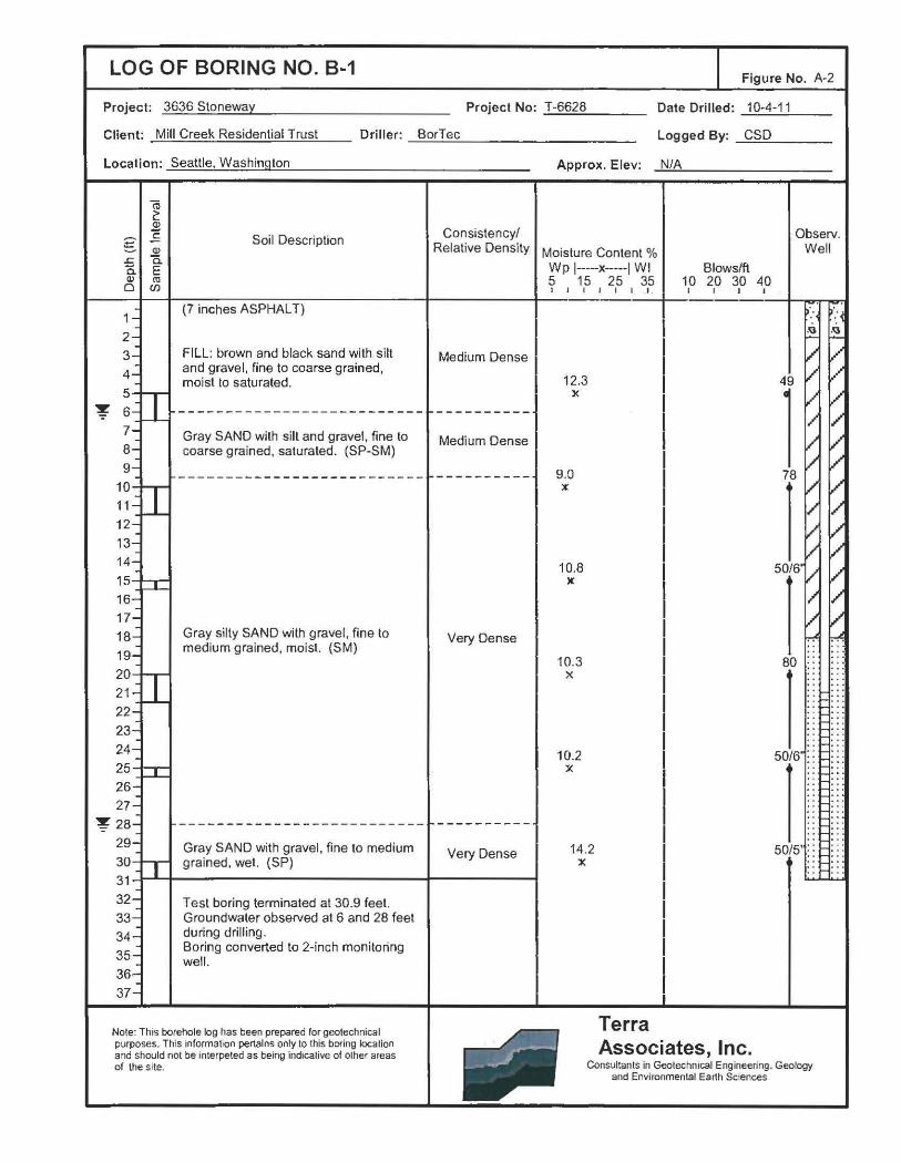
LOG OF BORING NO. B-1 Figure No. A-2
Project: 3636 Stoneway Project No: ...:.T....:-6:..:6:..=2:..=8 ___ _ Date Drilled: 10-4-11
Client: Mill Creek Residential Trust Driller: BorTec
Location: Seattle, Washington
~
m 2: 2 c g Q)
Soil Description
..c c. c. E Q) (ll
0 (/)
(7 inches ASPHALT)
2 3 FILL: brown and black sand with silt
4 and gravel, fine to coarse grained, moist to saturated.
5
6 --------------------------7 Gray SAND with silt and gravel, fine to 8 coarse grained, saturated. (SP-SM) 9 --------------------------10
11
12
13
14
15
16
17 Gray silty SAND with gravel, fine to medium grained, moist. (SM)
20 21
22
23
24 25
27
--------------------------Gray SAND with gravel, fine to medium grained, wet. (SP)
31
Test boring terminated at 30.9 feet. Groundwater observed at 6 and 28 feet during drilling. Boring converted to 2-inch monitoring well.
Note: This borehole log has been prepared for geotechnical purposes. This information penains only to this bDfing location and should not be interpeted as being indicative of other areas of the s ite.
Consistency/ Relative Density
Medium Dense
----------Medium Dense
----------
Very Dense
------ ----Very Dense
Logged By: .....:::C:.:::S:.:::D:...._ __ _
Approx. Elev: -"N:..:;/:.!..A!..-_______ _
Observ.
Moisture Content % Well
Wp 1---x----1 WI Blow sift 5 I
15 25 35 10 20 30 I I I I I I I I I ---- ----
12.3 )(
9.0 X
10.8 )(
10.3 X
10.2 X
14.2 X
Terra Associates, Inc.
40 I
.oa
49
1 78
l 50/6'
l 80
l 50/6'
l 50/5'
Consultants in Geotechnical Engineering. Geology and Environmental Earth Sciences
.oa
LOG OF BORING NO. 8~3 Figure No. A-4
Project : 3636 Stoneway Project No: --'T:._-..::.66::.:2::..:8:::..._ __ _ Date Drilled: ..;.1=-0-4--'---'- 1:.....:1 __ _
Client: Mill Creek Residential Trust Driller: BorTec
Location : Seattle, Washington
g .&: 0. Cl)
a
1
2
3
4
5
6
"iii 2: 2 c Cl)
a. E ro (/)
Soil Description
(7 .5 inches ASPHALT)
FILL: brown and black sand with silt and gravel, fine to coarse grained , moist to saturated.
Gray SAND with silt and gravel, fine to
Consistency( Relative Density
Medium Dense
"J! 7 8
coarse grained, saturated. (SP-SM) Medium Dense
9
10
11
12
13
14 15
16
17
18
19
20
21
22
23
24
25
26
27
28
29
30
31
32
33
34
35
36
37
Gray silty SAND with gravel, fine to medium grained, moist. (SM)
Test boring terminated at 30.5 feet. Groundwater observed at 7 feet during drilling. Boring converted to 2-inch monitoring well.
Note: This borehole log has been prepared for geotechnical purposes. This mformalion pertains only to this boring location and should not be lnterpeled as being indicative of other areas of the site.
Very Dense
Logged By: _c~s~D=-----
Approx. Elev: ..:..N:.:..:fA'-'----------
Moisture Content % Wp 1----x-----1 WI Blowsffl
? ' 1,5 ~0 20 3,0 4,0
4.9 ~
9.8 rfj
Y.
9.2 X
8.~ X
10.5 X
3{1
Terra Associates, Inc.
0
Observ. Well
.o;;s .o;;s
91/5'
l 50/5
l 50/3
l 50/4'
l 50/6'
Consultants In Geotechnical Engineering. Geology and Enwonmental Earth Sciences