Embed Size (px)
Citation preview
Geotechnical Study
PROJECT CORP-YARD BUILDING COVERED PARKING
PREPARED FOR
Mr. Dan Muelrath
General Manager
Diablo Water District
PROJECT LOCATION ROSE AVENUE
OAKLEY, CA
REPORT DATE:
October 28, 2020
PREPARED BY Bear Engineering Group, Inc.
3530 Kevin Place
Concord, CA [email protected]
ph: 925-550-7232
PROJECT NO. 106.2020-01
Bear Engineering Group, Inc. Earth Science Consultants
Mr. Dan Muelrath General Manager Diablo Water District 3990 Main Street Oakley, CA 94561 Subject: Geotechnical Proposal Corporation Yard, Administration and Shop Bldg. Rose Avenue Oakley, CA Dear Mr. Muelrath;
We are pleased to present this Geotechnical Study for the planned site improvements located at the subject site. This report describes the services performed and presents our conclusions and recommended geotechnical design criteria for construction. Recommendations in this report should be integrated into the design and implemented to during construction. Ancillary recommendations may be needed during construction, based on unforeseen circumstances that may arise during construction. It has been a pleasure to be of service to you on this project. Should you have any questions concerning the discoveries, recommendations or conclusions of the attached report, please contact this office at your earliest convenience. Very truly yours,
Bear Engineering Group, Inc.
Mark L. Schroeder, P.E., M.S.G.E. Principal Engineer
Bear Engineering Group, Inc. Earth Science Consultants
i | P A G E G E O T E C H N I C A L S T U D Y
C O R P - Y A R D
TABLE OF CONTENTS Page
INTRODUCTION
Section 1.1 - Project Description and Location 1 Section 1.2- Purpose 1 Section 1.3 - Scope 1
SITE SETTING Section 2.1 - Regional Geology 2 Section 2.2 - Local Geology 2 Section 2.3 - Seismic Setting 2 Section 2.4 - Seismic Probability 2 Section 2.5 – Surface Rupture 5
SITE EXPLORATION AND LABORATORY TESTING
Section 3.1 - Field Exploration 5 Section 3.2 - Laboratory Testing 6
SUBSURFACE CONDITIONS
Section 4.1 - Subsurface Conditions 6 Section 4.2 - Groundwater 6 Section 4.3 - Liquefaction 6 Section 4.4 - Lateral Spreading 7 Section 4.5 - Settlement Potential 7 Section 4.6 - Seismically Induced Ground Settlement 7 Section 4.7 - Expansive Soils 7 Section 4.6 - Findings 7
CONCLUSION Section 5.0 8
RECOMMENDATIONS Section 6.1 - Geotechnical Hazards 8 Section 6.2 - IBC 2012 Seismic Criteria 8 Section 6.3 - Grading 9 Section 6.4 - Foundation 10 Section 6.5 - Miscellaneous Flatwork 11 Section 6.6 - Utility Trenches 11 Section 6.7 - Drainage 11 Section 6.8 - Preliminary Pavement Design 12 Section 6.9 - Excavations 12 Section 6.10- Plan Review 13 Section 6.11 - Construction Observations 13 Section 6.12 - Site Safety 13 Section 6.13- Miscellaneous 13
LIMITATIONS 14
REFERENCES 15
LIST OF FIGURES
Bear Engineering Group, Inc. Earth Science Consultants
ii | P A G E G E O T E C H N I C A L S T U D Y
C O R P - Y A R D
Figure 1 - Vicinity Map Figure 2 - Geology Map Figure 3 - Fault Map Figure 4 - Probability Map Figure 5 - Liquefaction Map Figure 6 - Boring Location Map Figure 7 - Boring Log B1
Figure 8 - Boring Log B2
Figure 9 - Boring Log B3
Figure 10 - Boring Log B4
Figure 11 - Boring Log B5
Bear Engineering Group, Inc. Earth Science Consultants
1 | P A G E G E O T E C H N I C A L S T U D Y
C O R P - Y A R D
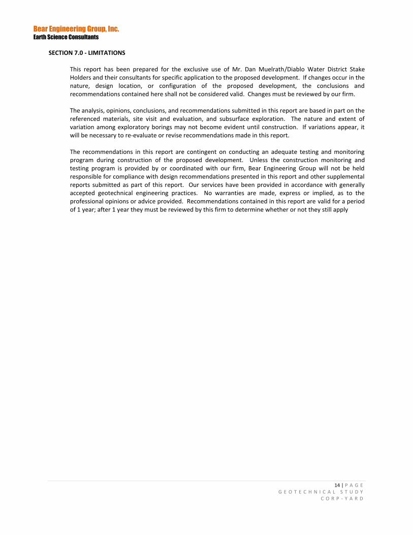
SECTION 1.0 INTRODUCTION Section 1.1 - Project Description and Location The subject site is located about 1 mile east from Downtown Oakley along Main Street in Contra Costa County as presented as Figure 1. The project consists of a 12, 000 square feet administration building, covered storage and parking. The lot is currently vacant gently sloping to the northwest with mature a few mature trees and low shrubs on the north end of the lot. Section 1.2- Purpose The purpose of this study was to evaluate the soil and geologic characteristics relevant to design and construction of the wall. Geotechnical foundation engineering design and recommendations are provided based on the physical characteristics of the subsurface materials and the geotechnical limitations created by the site's surface features. Section 1.3 - Scope The scope of our services for the proposed renovations, as set forth in our September 23, 2020, agreement included the following tasks as listed below: This phase of the study did not include assessments for toxic substances or soil or groundwater contamination.
Researching readily available geologic and seismic reports and maps of the area; including Review
of United States Geological Survey (USGS) Earthquake Hazards Program (2007), to select nearest fault source that could potentially impact the site.
Review of stereoscopic pairs of aerial photographs
A subsurface exploration program involving multiple borings with an average depth of 18.0 to 30.0 feet below existing grade unless bedrock refusal was encountered.
Soil Sampling for classification using ASTM D 2487 procedure.
Laboratory testing of selected soil samples to evaluate in-situ moisture/density and Unconfined Compression Strength (ASTM 2166) of the subsoil.
Reviewing of proposed residence layout to provided value engineering
Provide the near-surface Hazard Response Spectra and Design parameter seismic design criteria and per the California Building Code ASCE 7-16
Engineering analyses to develop geotechnical recommendations for design and construction of the
project.
Preparation of this engineering report.
Bear Engineering Group, Inc. Earth Science Consultants
2 | P A G E G E O T E C H N I C A L S T U D Y
C O R P - Y A R D
SECTION 2.0 SITE SETTING
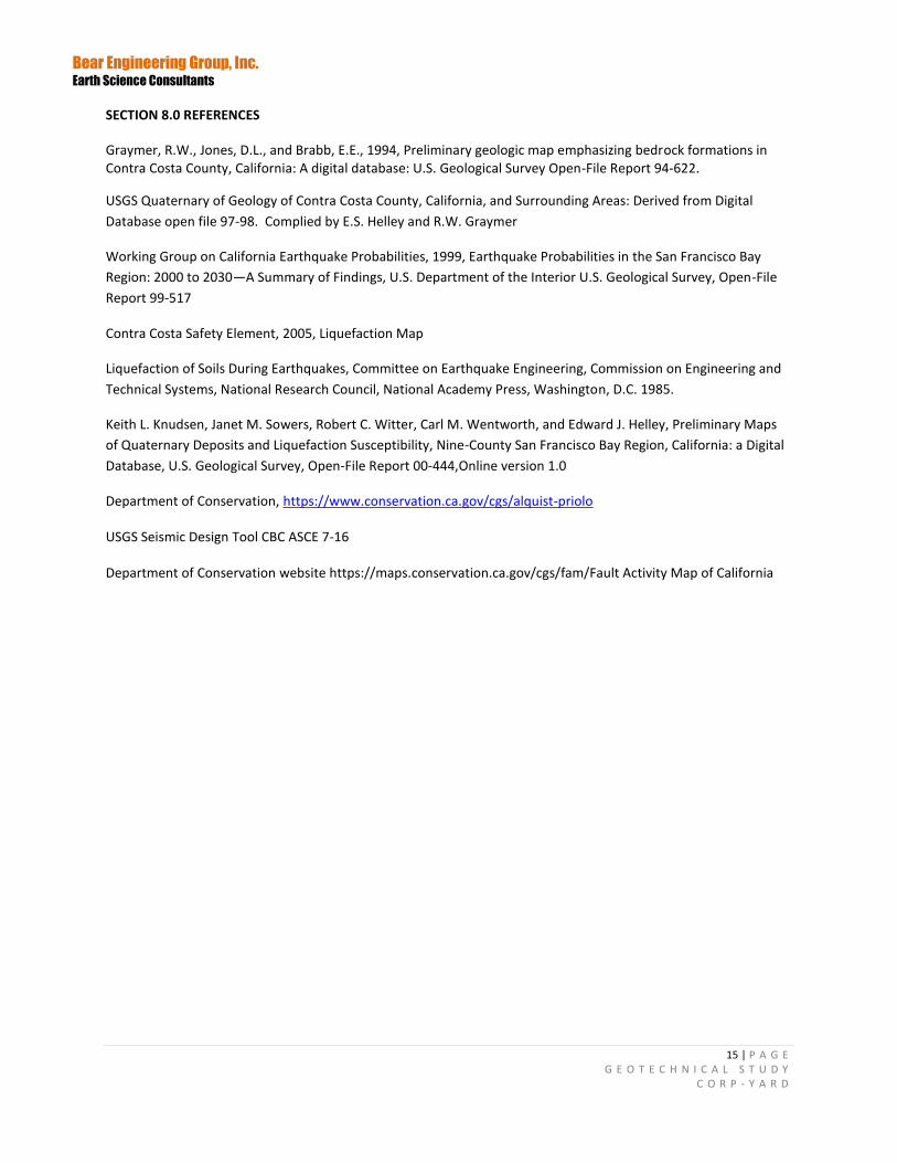
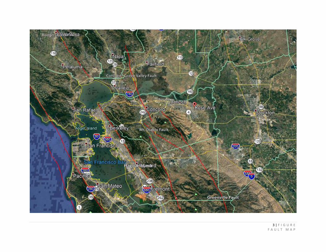
Section 2.1- Regional Geology Oakley is located within the California Coast Ranges geomorphic province. The region is generally defined by northwest-trending ridges and valleys that generally parallel the geologic structures, including the major fault systems. In general, the geologic structure and topography of the area is characteristic of the San Francisco East Bay area. Bedrock in the Coast Ranges consists of igneous, metamorphic and sedimentary rocks that range in age from Jurassic to Pleistocene. The present physiography and geology of the Coast Ranges are the result of deformation and deposition along the tectonic boundary between the North American plate and the Pacific plate. Plate boundary fault movements are largely concentrated along the well-known fault zones, which in the area include the San Andreas, Hayward, and Calaveras faults, as well as other lesser-order faults. The San Joaquin-Sacramento Delta lies at the junction of the Sacramento and San Joaquin rivers, the two main waterways that drain the Central Valley. In the San Joaquin- Sacramento Delta, sedimentary bedrock is up to 6 miles thick. This area consists of a braided pattern of brackish to freshwater tidally influenced channels and sloughs. Section 2.2- Local Geology The site is mapped by Helley and Graymer (1997) as underlain by Holocene and Pleistocene age dune sand and river delta deposits. This unit is described as consisting of fine-grained, very well-sorted, well-drained sedimentary deposits. During the Pleistocene, westerly winds formed laterally extensive dune fields atop the exposed landscape of the ancestral Delta. The eolian sand deposits were likely derived from glacial-age flood plains of the San Joaquin and Sacramento Rivers during outwash episodes that produced the late Pleistocene Modesto Formation, and subsequently covered by Holocene estuarine deposits of the modern Delta. R.W. Graymer, D.L. Jones and E.E. Brabb 1996 describe the site as undivided quaternary deposit. The surficial geology in the vicinity of the site is composed entirely of Holocene alluvial deposits and recent artificial fill, and late Tertiary sedimentary deposits. Figures 2 illustrates the general geology for the area. Section 2.3 - Seismic Setting The subject property, like all properties in the San Francisco Bay Area, is situated in a very seismically active region. Movement along faults of the San Andreas Fault system is generated by global forces shearing the eastern margin of the Pacific Plate along the western margin of the North American plate. In the Bay Area, the crustal movement does not proceed as uniform annual displacement along the faults, but instead, the forces driving the plates elastically deform the rocks adjacent to the faults until the rocks finally rupture and produce fault displacements. The sudden release of elastic strain energy that accompanies fault rupture is what causes the ground to shake. Table 1 provides estimated magnitude earthquakes from known active quaternary faults in the Bay Are with descriptions of the faults provided in subsequent paragraphs. Figure 3 illustrates the fault systems relative to the subject site. Section 2.4 - Seismic Probability The long-term occurrence of earthquakes modeling was founded on geologic and geophysical observations and constrained by plate tectonics. The Uniform California Earthquake Rupture Forecast, Version 3 (UCERF3) is a comprehensive model of earthquake occurrence for California. Based on their estimates the likelihood that California will experience a magnitude 8 or larger earthquake in the next 30 years increased from about 4.7% in UCERF2 to about 7% from there earlier estimates in the 1990’s. UCERF3 has
Bear Engineering Group, Inc. Earth Science Consultants
3 | P A G E G E O T E C H N I C A L S T U D Y
C O R P - Y A R D
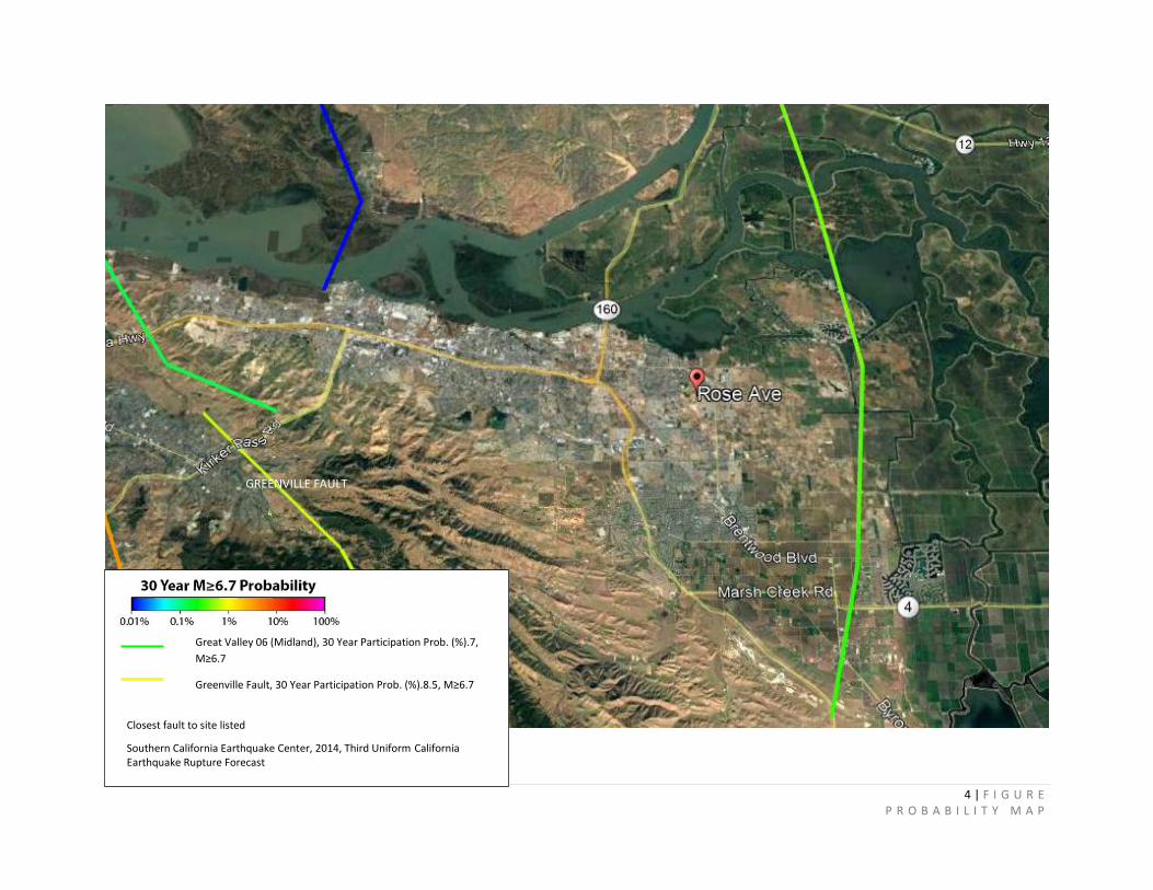
incorporated analysis of the gradual movement of hundreds of locations throughout California using space-based geodesy (GPS data) in order to estimate rates of deformation for faults lacking geologic data to arrive at their predictions. Figure 4 presents the probability of a 6.7 magnitude earthquake occurring from one of the fault systems listed in the next 30 years.
The Alquist-Priolo Earthquake Fault Zoning Act was passed by the California Legislature in 1972 to mitigate the hazard of surface faulting to structures. Its intent is to increase safety and minimize the loss of life during and immediately following earthquakes by facilitating seismic retrofits to strengthen buildings against ground shaking. The Act addresses only surface fault rupture; it is not directed toward other earthquake hazards. No faults have been mapped crossing the site, and the site is not within an Alquist-Priolo Special Studies Zone (California Geological Survey [CGS], 2007).
TABLE 1 QUARTINARY BAY AREA FAULTS
Faults Magnitude ELLSWORTH
Distance from Site (miles)
Fault Classification
Antioch Fault NA 7.6 W Potentially Active
Calaveras 7.3 21.0 SW Active
Concord-Green Valley Connected 6.5 17.0 W Active
Hayward 7.3 32.8 W Active
Greenville Clayton section 6.5 12.8 SW Active
Mount Diablo Thrust 6.7 17.8 SW Active
San Andres 8.0 51.9 W Active
Rodgers Creek 6.7 41.3 NW Active
An “active” fault is defined by the State of California as a fault that has had surface displacement within Holocene time (approximately the last 10,000 years). A “potentially active” fault has shown evidence of displacement during Quaternary time (approximately the last 2 million years). The fault classifications are derived from the Fault Activity Map of California and Adjacent Areas (Jennings, 1994).
Moment magnitude (Mw) is related to the physical size of a fault rupture and movement across a fault. Moment magnitude provides a physically meaningful measure of the size of a faulting event (CDFG, 1997). The Maximum Moment Magnitude Earthquake, derived from the joint CDMG/USGS Probabilistic Seismic Hazard Assessment for the State of California (USGS, 1996).
Antioch Fault: is located about 8 miles to the west of the subject site. The Antioch fault, mapped in 1973 after a pattern of property damage was noted, previously was considered active and was zoned under the Alquist-Priolo Earthquake Fault Zoning Act as potentially capable of surface rupture. However, a 1992 study by geologist C.J. Wills suggested that the Antioch fault should not be classified as active under the Alquist-Priolo Act and does not pose a surface faulting hazard (Contra Costa Times, 2008). The fault is no longer zoned by the State of California as an earthquake fault zone under the Alquist-Priolo Act. Concord-Green Valley: The Concord Fault is a Holocene active dextral strike-slip fault characterized by aseismic creep (rate 3.0 mm/yr. to 3.5 mm/yr.; Galehouse, 2000). Three sections area associated with this fault. Section 1 traverses the town of Concord and borders the western side of Lime Ridge. The northern end of the fault is assumed to connect with the Green Valley fault. The southern extent is relatively unknown but is thought to be to be connected to Mt. Diablo Thrust Dibblee (1980, c). Extending from Lime Ridge to the southern extent of the fault, the Concord Fault is delineated by a southwest-facing escarpment along the west side of Lime Ridge. Schwartz, 2008, suggests the activity on the fault to be during the Holocene age. The 2003 Working Group for California Earthquake Probability assigned a 4%
Bear Engineering Group, Inc. Earth Science Consultants
4 | P A G E G E O T E C H N I C A L S T U D Y
C O R P - Y A R D
probability that the Concord-Green Valley Fault system would produce a magnitude 6.5 or greater earthquake in the next 30 years. Calaveras Fault: Historically active major dextral strike-slip fault that is part of the larger San Andreas Fault system. The fault zone extends for about 90 miles from the San Ramon area southeast to about 19 miles south of Hollister. The fault is divided into 4 sections from north to south they are the Northern Calaveras, Central Calaveras, Southern Calaveras, and Paicines sections. North of Calaveras has a slip rate of 5-6 mm/yr. (Kelson and others, 1996). Between San Ramon and Alamo, the Danville – Alamo sub-section of the Northern Calaveras fault lies along the base of the northeast-facing Las Trampas Ridge, and is covered locally by large late Quaternary landslides. At the southern end of Las Trampas Ridge, the linear strand that extends northwestward across the San Ramon embayment was exposed in trenches for A-P investigations (ENGEO, Inc., 1977; 1978), and has prominent geomorphic expression north of Deerwood Drive. William Lettis & Associates, Inc. conducted a study in July 2002, to address the Northern Termination of the Calaveras Fault. They determined based detailed air photo analysis the dextral slip on the northern Calaveras fault, which dies out as a significant strike-slip fault somewhere in the vicinity of Danville, California, is transferred to the interior of the northern East Bay hills by a complex system of poorly integrated strike-slip faults and shear zones that are connected by restraining stepovers. Slip is transferred onto these structures from the Lafayette-Reliez Valley faults through a series of short restraining stepovers in the Briones hills region. Associated crustal shortening is responsible for creating the high topography of the Briones hills. Some slip on the Lafayette-Reliez Valley fault system also may be transferred northward onto the Franklin and Southampton faults. The Reliez, Southampton and Franklin Faults are for the most part poorly characterized strike-slip faults but may contribute to the approximately 4 to 7 mm/yr. of distributed dextral slip between the northern Calaveras and Concord faults. Great Valley Fault: The Great Valley fault system is a regional system of structurally segmented, blind west dipping thrust faults that are inferred to underlie the western boundary of the Central Valley (Working Group on California Earthquake Potential 1996). Based on seismic profiles, segmented portions of the Great Valley fault system underlie the region of the eastern Coast Ranges and valley floor boundary in the northwestern Sacramento Valley. In the northern Sacramento Valley, dip on the Great Valley fault segments steepens northward, ranging from shallow-dipping fault segments in the Sites area to steeper-dipping fault segments in the Orland area. Greenville Clayton Section: Historically active dextral strike-slip faults located in the Diablo Range. The fault zone extends from northwest of Livermore Valley along the Marsh Creek and Clayton faults towards Clayton Valley. Wright and others (1982) reported that fault-related topographic features are poorly developed and differ significantly from the Marsh Creek-Greenville segment. Colburn (1961) reported that the Clayton section is generally characterized by subdued saddles and subdued hill fronts. Unruh and Sawyer (1995, 1998) suggested that slip from the Greenville fault is transferred to the Concord fault along the Mt. Diablo fold and thrust belt and that only minimal slip continues to the Clayton fault. Hayward Fault: This fault is located in the eastern San Francisco Bay region and generally trends along and bounds the western side of the East Bay Hills (Aydin, 1982). The fault zone has three sections (Working Group on Northern California Earthquake Probabilities, 1996. The segment boundary between the Northern and Southern Hayward faults was long considered to be delineated by the location of the northern boundary of rupture associated with the Mw~7 1868 earthquake and the southern boundary of rupture associated with the 1836 (Working Group on California Earthquake Probabilities, 1988. The Hayward fault is characterized by fault creep along the Northern and Southern sections. A preferred average creep rate of 4.6 mm/yr. was reported by Lienkaemper and Galehouse (1997).
Bear Engineering Group, Inc. Earth Science Consultants
5 | P A G E G E O T E C H N I C A L S T U D Y
C O R P - Y A R D
Midland Fault: The Midland fault was active in late Cretaceous-Eocene time as a west-side-down normal fault throughout development of the Rio Vista basin, a structural sub-basin within the ancestral Great Valley forensic basin (Krug et al., 1992). Existing seismic source models have allocated a range of long-term average slip rates between about 0.1 mm/yr. to 1.0 mm/yr. to the Midland fault, and estimated maximum magnitudes up to about M 6.6 (Thrust Fault Subgroup, 1999; URS, 2006). Unconformity indicates uplift of the hanging wall of the Southern Midland fault between the towns of Brentwood and Rio Vista, terminating abruptly south of Lindsey Slough in Solano County. These relations suggest a maximum potential rupture length of about 30 km for the Southern Midland fault. Recent URS/JRB (2008) studies have characterization the Southern Midland fault as a seismic source. Midland Fault is not considered to be active. Mt. Diablo Thrust Fault: The Mount Diablo Thrust Fault is approximately 15 miles long, and dips at an angle of 38 degrees to the northeast. The Mount Diablo Thrust Fault is capable of generating an earthquake of magnitude MW=6.7. The predicted rupture surface begins 5 miles below the surface, and there is thus no surface expression of the fault, and a low likelihood of surface rupture in the event of a large earthquake on the fault. No large historic earthquakes are known to have occurred on the Mount Diablo Thrust Fault. The recurrence interval for large earthquakes along the fault is predicted to be about 400 years. The peak of Mt. Diablo is the topographic culmination of the northwest-trending Mt. Diablo anticline, a southwest-vergent fold located in a restraining step between the dextral Greenville and Concord faults. Unruh and Sawyer (1997) proposed that Mt. Diablo anticline is a fault-propagation fold developed above a blind, northeast-dipping thrust fault. Based on variations in the geometry of the fold along trend, it is possible that the Mt. Diablo thrust fault is divided into at least two structural segments that are offset in a right-stepping sense. The two segments are informally referred to herein as the “northwest segment” and “southeast segment”. The structural boundary between the two segments is interpreted to be near the town of Alamo, and is spatially associated with a northeast-trending alignment of earthquakes informally called the “Alamo swarm” (Oppenheimer and Macgregor-Scott, 1992). San Andreas Fault: San Andreas Fault zone is the principal element of the San Andreas Fault system, a network of faults with predominantly dextral strike-slip displacement that collectively accommodates the majority of relative N-S motion between the North American and Pacific plates. The San Andreas Fault zone is considered to be the Holocene and historically active dextral strike-slip fault that extends along most of coastal California. The fault zone first gained international scientific attention immediately following the great 1906 San Francisco earthquake. Tracy Stockton Fault: The fault crosses the county the in a southwest direction near Tracy to the northeast of Linden passing beneath the city of Stockton. The fault has no surface traces. Position of the fault has been determined by well log data. Subsurface data indicates no appreciable movement has occurred for over three million years suggesting the fault is not active. Section 2.5 – Surface Rupture Surface Rupture is the movement of a fault that breaks though the earth’s surface. NOT ALL earthquakes result in surface rupture. Our research indicates the site is not within an Alquist-Priolo Special Studies Zone.
SECTION 3.0 SITE EXPLORATIONS AND LABORATORY TESTING
Section 3.1 - Field Exploration Field exploration was conducted on October 19, 2020, consisting of five (5) exploratory boreholes to a maximum depth of approximately 28-feet below existing grade averaging about 20 feet. The borings were
Bear Engineering Group, Inc. Earth Science Consultants
6 | P A G E G E O T E C H N I C A L S T U D Y
C O R P - Y A R D
located within the footprint/pathway of the planned improvements as shown as Figure 5. The boring was drilled by a track mounted drilling unit using a 4-inch solid stem auger. Samples were gathered by driving a 2-inch Modified California Sampler at 18-inch intervals into underlying soil using a 140-pound hammer free falling 30-inches. The number of blows required to drive the sampler was recorded in 6-inch penetration intervals. The last 12 inches of penetration is provided on the Log of Borings as penetration resistance per foot. Blow counts provided have been corrected for energy efficiency. Both borings were backfilled with Portland cement by tremmie each bore whole. Description and identification of the samples were conducted in the field using ASTM D2488 and D2487 methods. Section 3.2 – Laboratory Testing Laboratory testing was conducted on selected soil samples to obtain data on density, moisture content (ASTM D2167), and soil description and identification (ASTM 2488). Laboratory test results are presented on the Log of Test Borings.
SECTION 4.0 SURFACE AND SUBSURFACE CONDITIONS
The depositional history of the Delta during the past one million years is the result of several kinds of cycles imposed by sea-level fluctuations from regional climates changes allowing for depositional waterway deposits to be placed throughout the Antioch and Oakley area. Our exploration found the site to be underlain by fine yellow/brown dry to moist alluvial Oakley sand deposits. Please refer to the Boring logs for specific descriptions of the sub-soil encountered. Section 4.2 - Groundwater Groundwater was localized in Borings 1 through 3 with no groundwater found in Borings 4 and 5. Groundwater was found between 13 and 16 feet directed in a north westerly direction. Water surface levels remained at equilibrium indicating no or very little head pressure. Please refer to Boring Logs for specifics. Groundwater levels have the potential to rise during winter months but we do not anticipate groundwater to be of a concern for this project. Section 4.3 - Liquefaction Soil liquefaction describes a phenomenon whereby a saturated or partially saturated soil temporarily drops in strength and acts as a fluid in response to an applied cyclic stress. The phenomenon is most often observed in saturated, loose low density or un-compacted, sandy soil. Shaking experienced at the subject site depends strongly on the type of deposits found near the surface. Generally there are three factors that need to take place for liquefaction to occur.
1. Loose, granular sediment 2. Saturation of the sediment 3. Strong shaking
Geologic maps indicate the site is underlain by Holocene Quaternary Deposits. Figure 5 liquefaction map indicates the site has a moderate potential for liquefying. Based on Field and laboratory data we would agree with readily available maps. Based on the depth of groundwater and the densities of the overburden we do not anticipate liquefaction manifestation rising to the surface during an earthquake.
Bear Engineering Group, Inc. Earth Science Consultants
7 | P A G E G E O T E C H N I C A L S T U D Y
C O R P - Y A R D
Section 4.4 - Lateral Spreading Lateral spreading is the lateral displacement of surficial blocks of sediment as a result of liquefaction in a subsurface layer. Earthquake shaking leading to liquefaction of saturated soil can result in lateral spreading where the soil undergoes a temporary loss of strength. Considering we do not expect liquefaction to occur this not of concern.
Section 4.5 - Settlement Potential Differential soil settlement occurs when significantly different densities and strengths of soil abutting one another occur or when seismic shaking induces one type of soil to settle more than the other. Uniform settlement has 3 components as follows;
1. Immediate settlement - elastic deformation of dry soil and moist and saturated soils without change to moisture content. 2. Primary consolidation settlement - volume change in saturated cohesive soils because of the expulsion of water from void spaces. 3. Secondary compression settlement - plastic adjustment of soil fabric in cohesive soils.
The site is underlain by sand deposits which has low elastic deformation with moisture changes. Coarse to fine grained material that has a high to medium permeability, allowing for pore pressures dissipate quickly essentially enabling for immediate settlement to occur. We expect 98-99 percent immediate consolidation will take place during grading activities. As water diffuses from between the soil grains from newly imposed loading conditions minor secondary consolidation will take place. We estimate 1-2 percent. Densities and varying thickness of subsurface layers suggest the potential for differential movement. To limit this risk grading uniform thickness with relatively consistent densities should be considered or a deep foundation system should be considered. Section 4.6 - Seismically Induced Ground Settlement Strong ground shaking can cause settlement by allowing sediment particles to become more tightly packed, thereby reducing pore space. Unconsolidated, loosely packed alluvial deposits are especially susceptible to this phenomenon. Densifying the soil below the building in accordance with section 6.3 will assist in reducing this risk. Section 4.7 - Expansive Soils Expansive soils are characterized by their ability to undergo significant volume change (shrink or swell) due to variations in moisture content. Our exploration program found near surface soil where predominantly granular which do not exhibit expansion and contraction properties. Section 4.8 – Findings The site is underlain by Holocene alluvial deposits coinciding well with geologic maps. Our borings found groundwater ranging from 13 to 16 with medium dense deposits suggesting a moderate potential for liquefaction. Densification below the proposed improvements will assist in dampening dynamic wave prorogation from an earthquake while inducing immediate settlement to take place. Some very minor secondary settlement from newly imposed building loads are expected as water escapes the void space
Bear Engineering Group, Inc. Earth Science Consultants
8 | P A G E G E O T E C H N I C A L S T U D Y
C O R P - Y A R D
causing some grain adjustments of soil particles. The surface soil does not demonstration expansion and contraction properties. The site is not considered to be a part of the Alquist-Priolo Special Studies Zone indicating a low potential for surface rupture to occur during a seismic event. Ground shaking is expected to be relatively strong from one of the fault systems listed in Table 1, although we do not anticipate lateral displacement. Seismically Induced ground settlement is difficult to predict because of numerous variables involved but a close seismic event has the ability to produce 2-3 inches of differential movements. The closest active fault to the site is the Greenville Fault about 13.0 miles southwest of the site. This fault has an 8.5 percent chance of rupture over the next 30 years according to Working Group on California Earthquake Probabilities.
SECTION 5.0 – CONCLUSION It is our opinion, based on an analysis of the data and information obtained from the site exploration, laboratory testing, and geotechnical evaluation and our experience and knowledge of the soil conditions in the area, the site is geotechnically suitable for the proposed improvements provided the recommendations contained herein are incorporated into the project designs and adhered to during construction. The principle adverse geotechnical factors affecting the development of the site are;
1. The site is located within a seismically active region and expected to be subjected to
moderately strong to strong ground shaking during the life of the structures. As a minimum, the building design should account for the effects of seismic activity in accordance with the latest edition of the California Building Code (CBC 2019).
2. The site has a moderate potential for liquefaction but is not anticipated to manifest at the surface in the form of sand boils. To enable the structure to perform uniformly during an earthquake event we recommend ground modification techniques as shown in Section 6.3.
SECTION 6.0 RECOMMENDATIONS
Section 6.1 – Geotechnical Hazards Risk of geotechnical hazards will always exist due to uncertainties of geologic conditions and the unpredictability of seismic activity in the Bay Area. However, in our opinion, based on available data, there are no indications of geotechnical hazards that would preclude use of the site for the proposed development. Section 6.2 - Seismic Criteria The proposed structures should be designed in accordance with local design practice to resist the lateral forces generated by ground shaking associated with a major earthquake occurring within the central portion of California. Based on the subsurface conditions encountered in our borings, our evaluation of the geology of the site, and extrapolating the alluvial soil site condition to the uppermost 100 feet of the soil profile, we have estimated the average N value of the soil at the site is on the order of 20 blows per foot which corresponds to a site classification of Site Class “D”.
Bear Engineering Group, Inc. Earth Science Consultants
9 | P A G E G E O T E C H N I C A L S T U D Y
C O R P - Y A R D
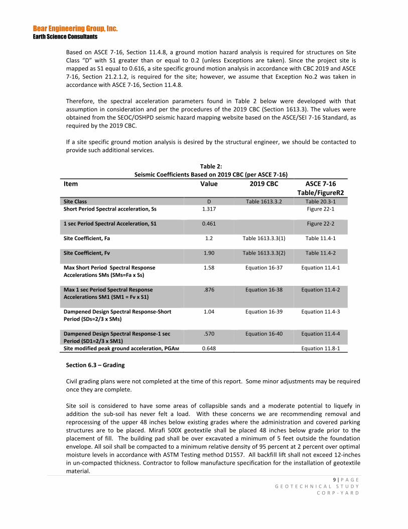
Based on ASCE 7-16, Section 11.4.8, a ground motion hazard analysis is required for structures on Site Class “D” with S1 greater than or equal to 0.2 (unless Exceptions are taken). Since the project site is mapped as S1 equal to 0.616, a site specific ground motion analysis in accordance with CBC 2019 and ASCE 7-16, Section 21.2.1.2, is required for the site; however, we assume that Exception No.2 was taken in accordance with ASCE 7-16, Section 11.4.8. Therefore, the spectral acceleration parameters found in Table 2 below were developed with that assumption in consideration and per the procedures of the 2019 CBC (Section 1613.3). The values were obtained from the SEOC/OSHPD seismic hazard mapping website based on the ASCE/SEI 7-16 Standard, as required by the 2019 CBC. If a site specific ground motion analysis is desired by the structural engineer, we should be contacted to provide such additional services.
Table 2: Seismic Coefficients Based on 2019 CBC (per ASCE 7-16)
Item Value 2019 CBC ASCE 7-16 Table/FigureR2
Site Class D Table 1613.3.2 Table 20.3-1 Short Period Spectral acceleration, Ss 1.317 Figure 22-1
1 sec Period Spectral Acceleration, S1 0.461 Figure 22-2
Site Coefficient, Fa 1.2 Table 1613.3.3(1) Table 11.4-1
Site Coefficient, Fv 1.90 Table 1613.3.3(2) Table 11.4-2
Max Short Period Spectral Response Accelerations SMs (SMs=Fa x Ss)
1.58 Equation 16-37 Equation 11.4-1
Max 1 sec Period Spectral Response Accelerations SM1 (SM1 = Fv x S1)
.876 Equation 16-38 Equation 11.4-2
Dampened Design Spectral Response-Short Period (SDs=2/3 x SMs)
1.04 Equation 16-39 Equation 11.4-3
Dampened Design Spectral Response-1 sec Period (SD1=2/3 x SM1)
.570 Equation 16-40 Equation 11.4-4
Site modified peak ground acceleration, PGAM 0.648 Equation 11.8-1
Section 6.3 – Grading Civil grading plans were not completed at the time of this report. Some minor adjustments may be required once they are complete. Site soil is considered to have some areas of collapsible sands and a moderate potential to liquefy in addition the sub-soil has never felt a load. With these concerns we are recommending removal and reprocessing of the upper 48 inches below existing grades where the administration and covered parking structures are to be placed. Mirafi 500X geotextile shall be placed 48 inches below grade prior to the placement of fill. The building pad shall be over excavated a minimum of 5 feet outside the foundation envelope. All soil shall be compacted to a minimum relative density of 95 percent at 2 percent over optimal moisture levels in accordance with ASTM Testing method D1557. All backfill lift shall not exceed 12-inches in un-compacted thickness. Contractor to follow manufacture specification for the installation of geotextile material.
Bear Engineering Group, Inc. Earth Science Consultants
10 | P A G E G E O T E C H N I C A L S T U D Y
C O R P - Y A R D
Prior to any grading work the following shall be done;
Clearing, Stripping, Grubbing, and Debris Removal
Trees, roots, vegetation, and organic surficial soil shall be removed from structural areas unless specified otherwise by the Geotechnical Engineer or the Engineer's Representative. The depth of organic soil to be removed will be recommended by the Geotechnical Engineer or the Engineer's Representative but, in general, will probably vary from about 4 to 6 inches.
Strippings are defined as surface vegetation and organic surficial soil. Strippings may not be used in fill unless specifically authorized and observed by the Geotechnical Engineer or the Engineer's Representative. Stripping material may be stockpiled for landscaping use, with the approval of the landscape architect. The final clearing, stripping, and grubbing shall be approved by the Geotechnical Engineer before further grading is started.
Concrete pavement, building rubble, concrete foundations and any other debris noted at or below the existing ground surface should be removed as part of the site preparation for the proposed construction area.
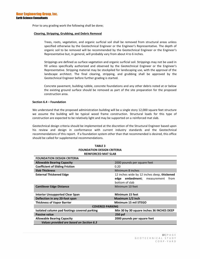
Section 6.4 – Foundation We understand that the proposed administration building will be a single story 12,000 square feet structure we assume the building will be typical wood frame construction. Structural loads for this type of construction are expected to be relatively light and may be supported on a reinforced mat slab. Geotechnical design criteria should be implemented at the discretion of the Structural Engineer based upon his review and design in conformance with current industry standards and the Geotechnical recommendations of this report. If a foundation system other than that recommended is desired, this office should be called for supplemental recommendations.
TABLE 3 FOUNDATION DESIGN CRITERIA
REINFORCED MAT SLAB
FOUNDATION DESIGN CRITERIA
Allowable Bearing Capacity 2000 pounds per square feet Coefficient of Sliding Friction 0.20 Slab Thickness Minimum 8 inches External Thickened Edge 12 inches wide by 12 inches deep, thickened
edge embedment; measurement from bottom of slab
Cantilever Edge Distance
Minimum 10 feet
Interior Unsupported Clear Span Minimum 15 feet Deflection in any 20-foot span Maximum 1/2 inch Thickness of Vapor Barrier Minimum 15 mil STEGO
COVERED PARKING Isolated column pad footings covered parking Min 30 by 30 square inches 36 INCHES DEEP Passive value 250 psf Allowable Bearing Capacity 2000 pounds per square feet
Values provided are based on Section 6.3
Bear Engineering Group, Inc. Earth Science Consultants
11 | P A G E G E O T E C H N I C A L S T U D Y
C O R P - Y A R D
The above values are based upon the anticipated soil conditions located in the upper surficial soil after grading is complete. A 4-inch thick capillary break of pea gravel or clean, crushed 3/4-inch rock should be utilized unless deemed unnecessary by the Structural Engineer above the rock material shall be a vapor barrier (See Table 3) followed by 3 inches of clean sand.. Recommendations presented in the American Concrete Institute manual should be complied with for all concrete placements and curing operations. Improper curing techniques and/or excessive slump (water-cement ratio) could cause excessive shrinkage, cracking or curling. Concrete slabs should be allowed to cure adequately before placing vinyl or other moisture sensitive floor coverings. We recommend that the project Structural Engineer also consider specifying air-entrainment for the concrete mix design to reduce the permeability of the concrete slab. Section 6.5 - Miscellaneous Flatwork All exterior concrete flat work shall be structurally independent of the foundation to provide freedom of movement. All walkways shall be a minimum thickness of four inches and be underlain by a 4-inch thick cushion of "sand or crushed rock". Reinforcement of the walkways shall consist of a minimum No. 3 reinforcement bars placed in a grid pattern at 18 inches on center or as directed by the structural engineer. Subsoil material shall be moisture conditioned and compacted to a relative compaction of 90 percent at 3-2-3 percent over optimum moisture values. Ponding of storm or irrigation water adjacent to any structure is prohibited. Walkways shall be designed to slope to area drains or a minimum grade of 2% away from structures discharging to a suitable controlled location. It would be beneficial to extend the edge of the slab walkways 6 to 8 inches into the ground to assist in preventing moisture variation below the outer edges and help prevent soil and slab movement.
The owners must be advised that some vertical displacement of exterior flatwork should be anticipated. Proper site drainage, maintenance and controlling landscape irrigation is recommended to reduce the amount of vertical displacement that may occur. Section 6.6 - Utility Trenches
All trenches should be backfilled with native materials compacted uniformly in accordance with Section 6.3 If local building codes require the usage of sand as the trench backfill, all utility trenches entering the building must be provided with an impervious seal of either cohesive soil or lean concrete where the trench passes under the foundation perimeter. The impervious plug should extend 2 feet into, and out of, the building perimeter. Jetting of trench backfill is not recommended as it may result in an unsatisfactory degree of compaction. All disturbed areas within 5 feet of the foundation from trench excavation, including electric lines, must be reprocessed as engineered fill.
Section 6.7 – Drainage
Groundwater shall be captured outside the building footprint as needed. Suggestions for proper drainage of the site are as follows;
1. Down-spout locations directed to solid tight-line connections discharging to a suitable location away from the foundation.
2. To comply with the Clean Water Act roof water may be discharged to a filter planter box or other filtration detention point as directed by Civil Engineer.
Bear Engineering Group, Inc. Earth Science Consultants
12 | P A G E G E O T E C H N I C A L S T U D Y
C O R P - Y A R D
3. Tight-line pipe to be shown on civil drawings we recommended 4-inch diameter SDR 35 pipe.
4. Sufficient drop inlets shall be placed in flat work areas to reduce the potential for ponding.
5. A five percent gradient should be maintained for landscaped areas immediately adjacent to the structure (within 5-feet). In general, water should not be allowed to collect near the surface of the foundation or floor slab areas of the structures during or after construction
Section 6.8 - Preliminary Pavement Design
We recommend that the preliminary pavement section consist of a minimum 2-1/2-inches asphaltic concrete over a minimum of 6-inches aggregate base rock. Grade elevation changes should be anticipated to accommodate a modified pavement thickness unless a predetermined section can be agreed upon during the plan approval process. To perform to its greatest efficiency, the pavement section requires the following construction criteria:
1. Remove organic and deleterious materials from all pavement subgrade
2. The upper 12-inches of subgrade soil shall be compacted to a minimum relative
compaction of 95 percent at a moisture content of 2 percent over the optimum moisture content. All pavement subgrade should be stable with no “pumping” at the time base rock is placed.
3. Use only good quality materials of the type and minimum thickness specified. All base
rock should meet the Standard Specifications of the State of California for Class II base rock and be angular in shape.
4. Compact the base rock uniformly to a minimum relative compaction of 95 percent. 5. Place the asphaltic concrete only during periods of fair weather when the free air
temperature is within the prescribed limits as set forth by the Asphalt Concrete Institute.
6. Compact all trench backfill under the pavement to reduce fill settlement and minimize
pavement damage that may result from such settlement. Trench backfill must be performed in accordance with the recommendations in the Utility Trench section of this report. Mechanical compaction is recommended because material placed by jetting or ponding will probably not attain satisfactory densities.
7. Provide adequate drainage to prevent surface water from migrating into the pavement subgrade soil from behind curb-and-gutter sections. The need for curb and gutter subdrains should be evaluated based on the results of mass grading.
Section 6.9 - Excavations
The contractor is solely responsible for protecting excavations by shoring, sloping, benching or other means as required to maintain stability of both the excavation sides and bottom. Bear Engineering Group does not assume any responsibility for construction site safety or the activities of the contractor.
Bear Engineering Group, Inc. Earth Science Consultants
13 | P A G E G E O T E C H N I C A L S T U D Y
C O R P - Y A R D
Section 6.10 – Plan Review
Before submitting design drawings and construction documents to the appropriate local agency for approval, we recommend that copies of the documents be reviewed by our firm to confirm that the recommendations in this report have been effectively incorporated into the design. Section 6.11 – Construction Observations
Our office should be contacted prior at a minimum for the following;
1. Sub-grade excavation work across the building envelope 2. During backfill for compaction testing 3. Footing excavations
The purpose of these visits is to observe the work performed to conduct whatever testing is necessary and to provide recommendations as needed.
At the completion of foundation excavations or if backfill is conducted, we will submit a report that summarizes the work observed and the results of all tests performed by our firm during the construction phase of the project, along with any supplemental recommendations that may be warranted. To allow proper scheduling so that our personnel are present at the job site when 4 working days needed advance notice is required. Section 6.12 - Site Safety All excavations and site work must comply with applicable local, state, and federal safety regulations. Construction site safety is the responsibility of the contractor, who shall be solely responsible for the means, methods, and sequencing of construction operations. Our services and recommendations for site safety are available upon request and are advisory only and supplemental to current regulatory standards. Bear Engineering Group, Inc. assumes no responsibility for construction site safety or the contractor's activities during any phase of the construction project. Section 6.13 – Miscellaneous Our exploration did not reveal the presence of buried items such as leaching fields, septic tanks, storage tanks, etc. at the location of the borings. If such items are encountered during grading or demolition, our firm should be notified immediately to provide recommendations for proper disposal procedures.
Bear Engineering Group, Inc. Earth Science Consultants
14 | P A G E G E O T E C H N I C A L S T U D Y
C O R P - Y A R D
SECTION 7.0 - LIMITATIONS
This report has been prepared for the exclusive use of Mr. Dan Muelrath/Diablo Water District Stake Holders and their consultants for specific application to the proposed development. If changes occur in the nature, design location, or configuration of the proposed development, the conclusions and recommendations contained here shall not be considered valid. Changes must be reviewed by our firm. The analysis, opinions, conclusions, and recommendations submitted in this report are based in part on the referenced materials, site visit and evaluation, and subsurface exploration. The nature and extent of variation among exploratory borings may not become evident until construction. If variations appear, it will be necessary to re-evaluate or revise recommendations made in this report. The recommendations in this report are contingent on conducting an adequate testing and monitoring program during construction of the proposed development. Unless the construction monitoring and testing program is provided by or coordinated with our firm, Bear Engineering Group will not be held responsible for compliance with design recommendations presented in this report and other supplemental reports submitted as part of this report. Our services have been provided in accordance with generally accepted geotechnical engineering practices. No warranties are made, express or implied, as to the professional opinions or advice provided. Recommendations contained in this report are valid for a period of 1 year; after 1 year they must be reviewed by this firm to determine whether or not they still apply
Bear Engineering Group, Inc. Earth Science Consultants
15 | P A G E G E O T E C H N I C A L S T U D Y
C O R P - Y A R D
SECTION 8.0 REFERENCES
Graymer, R.W., Jones, D.L., and Brabb, E.E., 1994, Preliminary geologic map emphasizing bedrock formations in Contra Costa County, California: A digital database: U.S. Geological Survey Open-File Report 94-622.
USGS Quaternary of Geology of Contra Costa County, California, and Surrounding Areas: Derived from Digital
Database open file 97-98. Complied by E.S. Helley and R.W. Graymer
Working Group on California Earthquake Probabilities, 1999, Earthquake Probabilities in the San Francisco Bay
Region: 2000 to 2030—A Summary of Findings, U.S. Department of the Interior U.S. Geological Survey, Open-File
Report 99-517
Contra Costa Safety Element, 2005, Liquefaction Map
Liquefaction of Soils During Earthquakes, Committee on Earthquake Engineering, Commission on Engineering and
Technical Systems, National Research Council, National Academy Press, Washington, D.C. 1985.
Keith L. Knudsen, Janet M. Sowers, Robert C. Witter, Carl M. Wentworth, and Edward J. Helley, Preliminary Maps
of Quaternary Deposits and Liquefaction Susceptibility, Nine-County San Francisco Bay Region, California: a Digital
Database, U.S. Geological Survey, Open-File Report 00-444,Online version 1.0
Department of Conservation, https://www.conservation.ca.gov/cgs/alquist-priolo USGS Seismic Design Tool CBC ASCE 7-16 Department of Conservation website https://maps.conservation.ca.gov/cgs/fam/Fault Activity Map of California

16 | P A G E G E O T E C H N I C A L S T U D Y
C O R P - Y A R D
FIGURES
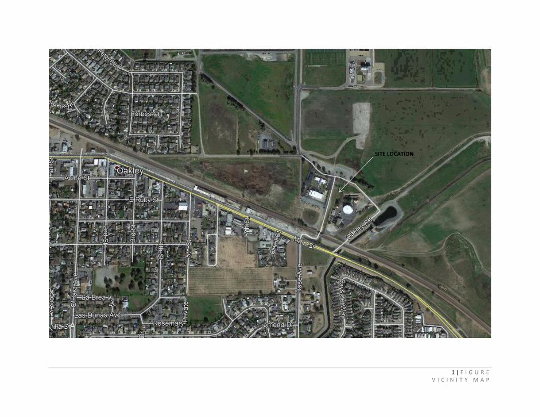
1 | F I G U R E V I C I N I T Y M A P
SITE LOCATION
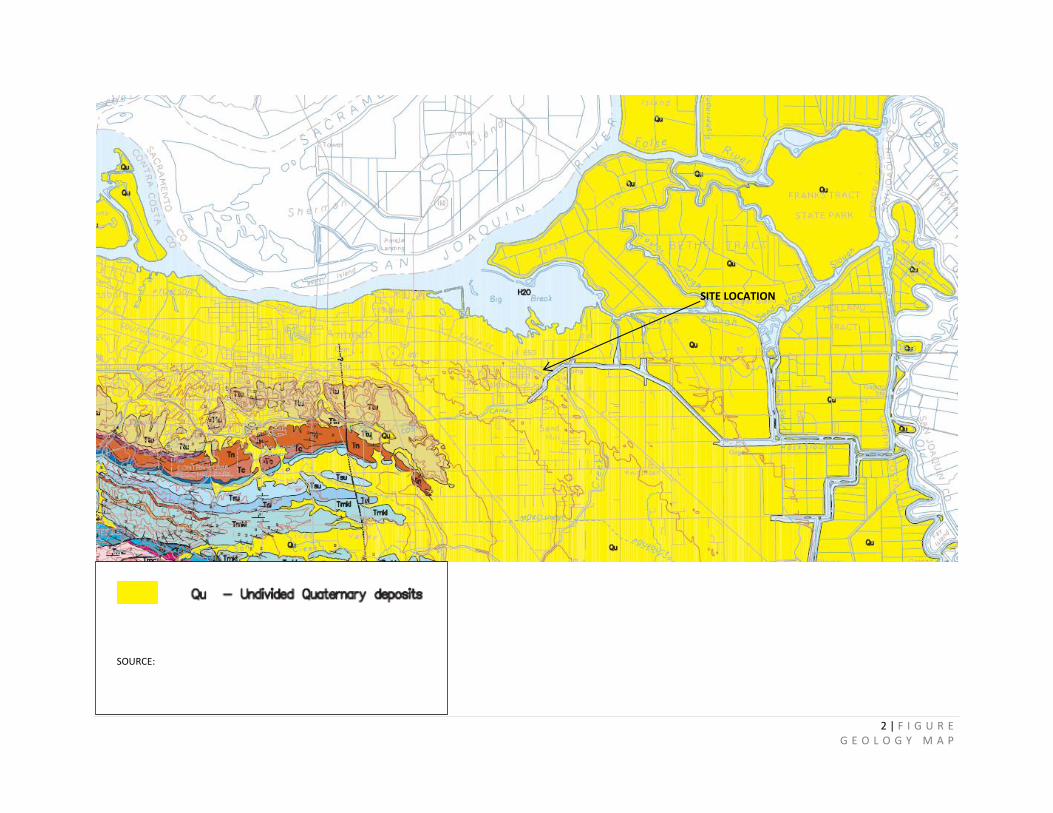
2 | F I G U R E G E O L O G Y M A P
SITE LOCATION
SOURCE:
3 | F I G U R E F A U L T M A P
4 | F I G U R E P R O B A B I L I T Y M A P
Great Valley 06 (Midland), 30 Year Participation Prob. (%).7,
M≥6.7
Closest fault to site listed
Southern California Earthquake Center, 2014, Third Uniform California Earthquake Rupture Forecast
GREENVILLE FAULT
Greenville Fault, 30 Year Participation Prob. (%).8.5, M≥6.7
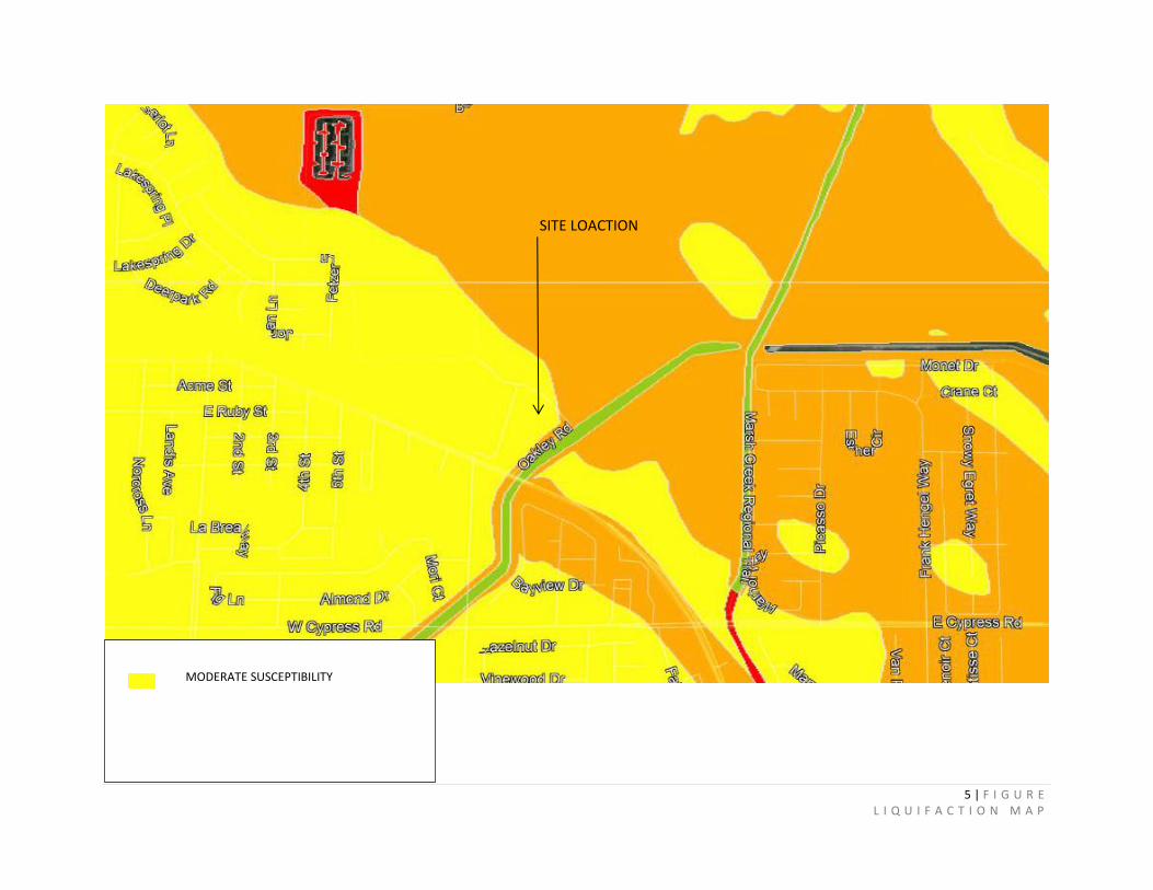
5 | F I G U R E L I Q U I F A C T I O N M A P
SITE LOACTION
MODERATE SUSCEPTIBILITY
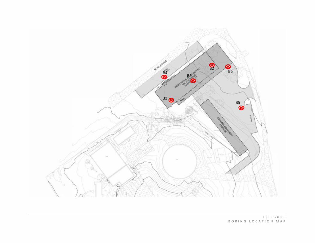
6 | F I G U R E B O R I N G L O C A T I O N M A P
B1
B2 B4
B3
B5
B6
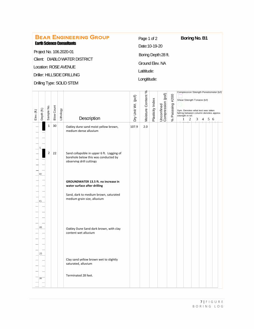
7 | F I G U R E B O R I N G L O G
Bear Engineering Group
Earth Science Consultants
Ele
v. (
ft.)
De
pth
(ft.)
Sa
mp
le N
o.
Blo
w C
ou
nt
Lith
olo
gy
Description
Dry
Un
it W
t. (
pcf)
Mo
istu
re C
on
ten
t %
Pla
sticity I
nd
ex
Un
co
nfin
ed
C
om
pre
ssio
n (
psf)
% P
asssin
g #
20
0
Compression Strength Penetrometer (tsf)
Shear Strength Torvane (tsf)
Sym. Denotes what test was takenfalling between column denotes approx. strength in tsf.
1 2 3 4 5 6
5
10
15
20
25
30
__
__
__
__
__
__
__
__
__
__
__
__
__
__
__
__
__
__
__
__
__
__
__
__
__
__
__
__
__
__
__
__
__
__
__
__
__
__
__
__
__
__
__
__
Boring No. B1
Boring Depth:28 ft.
Latititude:
Longititude:
Ground Elev. NA
Page 1 of 2
Date:10-19-20
Project No. 106.2020-01
Client: DIABLO WATER DISTRICT
Location: ROSE AVENUE
Driller: HILLSIDE DRILLING
Drilling Type: SOLID STEM
1 30 Oakley dune sand moist yellow brown, medium dense alluvium
2 Sand collapsible in upper 6 ft. Logging of borehole below this was conducted by observing drill cuttings
GROUNDWATER 13.5 ft. no increase in water surface after drilling
Sand, dark to medium brown, saturated medium grain size, alluvium
Oakley Dune Sand dark brown, with clay content wet alluvium
Clay sand yellow brown wet to slightly saturated, alluvium
Terminated 28 feet.
22
107.9 2.0
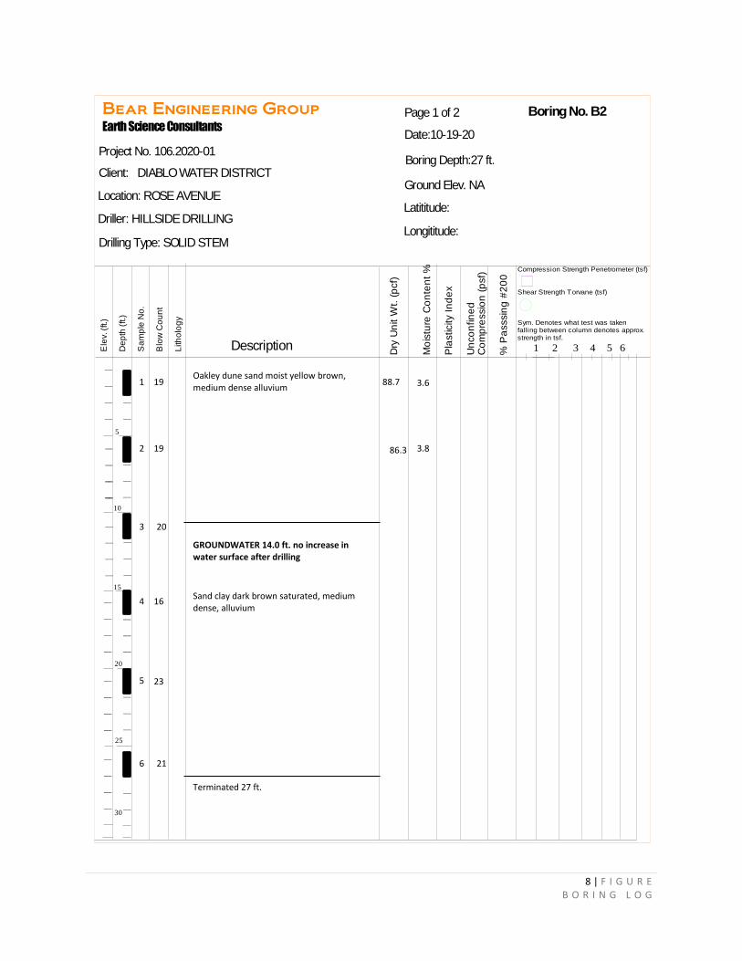
8 | F I G U R E B O R I N G L O G
Bear Engineering Group
Earth Science Consultants
Ele
v. (
ft.)
De
pth
(ft.)
Sa
mp
le N
o.
Blo
w C
ou
nt
Lith
olo
gy
Description
Dry
Un
it W
t. (
pcf)
Mo
istu
re C
on
ten
t %
Pla
sticity I
nd
ex
Un
co
nfin
ed
C
om
pre
ssio
n (
psf)
% P
asssin
g #
20
0
Compression Strength Penetrometer (tsf)
Shear Strength Torvane (tsf)
Sym. Denotes what test was takenfalling between column denotes approx. strength in tsf.
1 2 3 4 5 6
5
10
15
20
25
30
__
__
__
__
__
__
__
__
__
__
__
__
__
__
__
__
__
__
__
__
__
__
__
__
__
__
__
__
__
__
__
__
__
__
__
__
__
__
__
__
__
__
__
__
Boring No. B2
Boring Depth:27 ft.
Latititude:
Longititude:
Ground Elev. NA
Page 1 of 2
Date:10-19-20
Project No. 106.2020-01
Client: DIABLO WATER DISTRICT
Location: ROSE AVENUE
Driller: HILLSIDE DRILLING
Drilling Type: SOLID STEM
1 Oakley dune sand moist yellow brown, medium dense alluvium
19
2 19
3 20
GROUNDWATER 14.0 ft. no increase in water surface after drilling
4 16 Sand clay dark brown saturated, medium dense, alluvium
5 23
6 21
Terminated 27 ft.
88.7 3.6
86.3 3.8
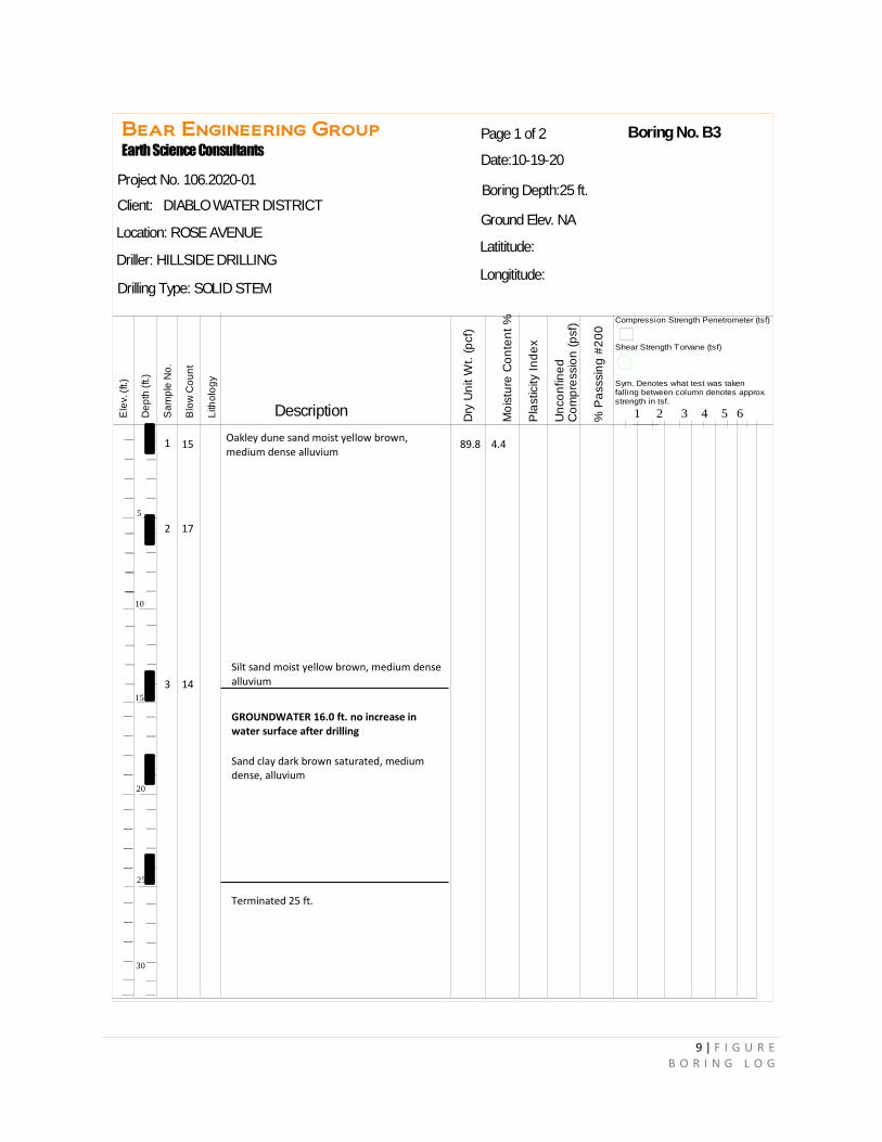
9 | F I G U R E B O R I N G L O G
Bear Engineering Group
Earth Science Consultants
Ele
v. (
ft.)
De
pth
(ft.)
Sa
mp
le N
o.
Blo
w C
ou
nt
Lith
olo
gy
Description
Dry
Un
it W
t. (
pcf)
Mo
istu
re C
on
ten
t %
Pla
sticity I
nd
ex
Un
co
nfin
ed
C
om
pre
ssio
n (
psf)
% P
asssin
g #
20
0
Compression Strength Penetrometer (tsf)
Shear Strength Torvane (tsf)
Sym. Denotes what test was takenfalling between column denotes approx. strength in tsf.
1 2 3 4 5 6
5
10
15
20
25
30
__
__
__
__
__
__
__
__
__
__
__
__
__
__
__
__
__
__
__
__
__
__
__
__
__
__
__
__
__
__
__
__
__
__
__
__
__
__
__
__
__
__
__
__
Boring No. B3
Boring Depth:25 ft.
Latititude:
Longititude:
Ground Elev. NA
Page 1 of 2
Date:10-19-20
Project No. 106.2020-01
Client: DIABLO WATER DISTRICT
Location: ROSE AVENUE
Driller: HILLSIDE DRILLING
Drilling Type: SOLID STEM
1 15 Oakley dune sand moist yellow brown, medium dense alluvium
2 17
3 14
GROUNDWATER 16.0 ft. no increase in water surface after drilling
Silt sand moist yellow brown, medium dense alluvium
Sand clay dark brown saturated, medium dense, alluvium
Terminated 25 ft.
89.8 4.4

10 | F I G U R E B O R I N G L O G
Bear Engineering Group
Earth Science Consultants
Ele
v. (
ft.)
De
pth
(ft.)
Sa
mp
le N
o.
Blo
w C
ou
nt
Lith
olo
gy
Description
Dry
Un
it W
t. (
pcf)
Mo
istu
re C
on
ten
t %
Pla
sticity I
nd
ex
Un
co
nfin
ed
C
om
pre
ssio
n (
psf)
% P
asssin
g #
20
0
Compression Strength Penetrometer (tsf)
Shear Strength Torvane (tsf)
Sym. Denotes what test was takenfalling between column denotes approx. strength in tsf.
1 2 3 4 5 6
5
10
15
20
25
30
__
__
__
__
__
__
__
__
__
__
__
__
__
__
__
__
__
__
__
__
__
__
__
__
__
__
__
__
__
__
__
__
__
__
__
__
__
__
__
__
__
__
__
__
Boring No. B4
Boring Depth:20 ft.
Latititude:
Longititude:
Ground Elev. NA
Page 1 of 2
Date:10-19-20
Project No. 106.2020-01
Client: DIABLO WATER DISTRICT
Location: ROSE AVENUE
Driller: HILLSIDE DRILLING
Drilling Type: SOLID STEM
Oakley dune sand moist yellow brown, medium dense alluvium 1 27
2 16 Silt sand, yellow brown, moist to wet medium dense alluvium
Sand clay dark brown saturated, medium dense, alluvium
Terminated 20 ft.
3
4
22
20
73.6 3.8 1.8
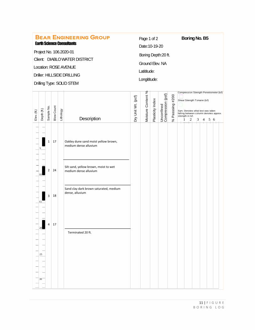
11 | F I G U R E B O R I N G L O G
Bear Engineering Group
Earth Science Consultants
Ele
v. (
ft.)
De
pth
(ft.)
Sa
mp
le N
o.
Blo
w C
ou
nt
Lith
olo
gy
Description
Dry
Un
it W
t. (
pcf)
Mo
istu
re C
on
ten
t %
Pla
sticity I
nd
ex
Un
co
nfin
ed
C
om
pre
ssio
n (
psf)
% P
asssin
g #
20
0
Compression Strength Penetrometer (tsf)
Shear Strength Torvane (tsf)
Sym. Denotes what test was takenfalling between column denotes approx. strength in tsf.
1 2 3 4 5 6
5
10
15
20
25
30
__
__
__
__
__
__
__
__
__
__
__
__
__
__
__
__
__
__
__
__
__
__
__
__
__
__
__
__
__
__
__
__
__
__
__
__
__
__
__
__
__
__
__
__
Boring No. B5
Boring Depth:20 ft.
Latititude:
Longititude:
Ground Elev. NA
Page 1 of 2
Date:10-19-20
Project No. 106.2020-01
Client: DIABLO WATER DISTRICT
Location: ROSE AVENUE
Driller: HILLSIDE DRILLING
Drilling Type: SOLID STEM
1 17 Oakley dune sand moist yellow brown, medium dense alluvium
Silt sand, yellow brown, moist to wet medium dense alluvium
Sand clay dark brown saturated, medium dense, alluvium
2
3
4
24
18
17
Terminated 20 ft.