Embed Size (px)
Citation preview
Dow
nloa
ded
from
asc
elib
rary
.org
by
SOU
TH
ER
N C
AL
IFO
RN
IA U
NIV
ER
SIT
Y o
n 08
/27/
13. C
opyr
ight
ASC
E. F
or p
erso
nal u
se o
nly;
all
righ
ts r
eser
ved.

Geotechnical Testing, Observation, and Documentation
Second Edition
Dow
nloa
ded
from
asc
elib
rary
.org
by
SOU
TH
ER
N C
AL
IFO
RN
IA U
NIV
ER
SIT
Y o
n 08
/27/
13. C
opyr
ight
ASC
E. F
or p
erso
nal u
se o
nly;
all
righ
ts r
eser
ved.
Other Titles of Interest
Degrees of Belief: Subjective Probability and Engineering Judgment by StEvEn vick (AScE Press, 2002). Examines the intersection of probability and risk analysis with professional judgment and expertise, from a geotechnical perspective. (iSbn 978-0-7844-0598-7)
Design of Shallow Foundations by SAmuEl E. FrEnch (AScE Press, 1999). Details a complete “how to” procedure for the design of shallow foundations commonly used with the low-rise structures of today’s building codes. (iSbn 978-0-7844-0371-6)
Geomechanics II: Testing, Modeling, and Simulation EDitED by Poul v. lADE AnD tEruo nAkAi (AScE Proceedings, 2006). current relevant research gathered by investigators from Japan and the united States, covering various geomechanics issues such as experimentation, constitutive modeling, and numerical simulations. (iSbn 978-0-7844-0870-4)
Geotechnical Measurements: Lab and Field EDitED by W. AllEn mArr
(AScE Proceedings, 2000). Provides insight into the state-of-the-practice in geotechnical measurements. (iSbn 978-0-7844-0518-5)
Karl Terzaghi: The Engineer as Artist by richArD E. GooDmAn (AScE Press, 1999). biographical account of the friendships, conflicts, and enormous successes of the man who laid the groundwork for soil mechanics. (iSbn 978-0-7844-0364-8)
Soil Sampling by thE u.S. Army corPS oF EnGinEErS
(AScE Press, 2000). Presents a summary of commonly accepted soil sampling practices and procedures to assist geotechnical personnel performing actual field studies. (iSbn 978-0-7844-0375-4)
Dow
nloa
ded
from
asc
elib
rary
.org
by
SOU
TH
ER
N C
AL
IFO
RN
IA U
NIV
ER
SIT
Y o
n 08
/27/
13. C
opyr
ight
ASC
E. F
or p
erso
nal u
se o
nly;
all
righ
ts r
eser
ved.
Geotechnical Testing, Observation, and Documentation
Second Edition
tim Davis
Dow
nloa
ded
from
asc
elib
rary
.org
by
SOU
TH
ER
N C
AL
IFO
RN
IA U
NIV
ER
SIT
Y o
n 08
/27/
13. C
opyr
ight
ASC
E. F
or p
erso
nal u
se o
nly;
all
righ
ts r
eser
ved.
Library of Congress Cataloging-in-Publication Data
Davis, tim Geotechnical testing, observation, and documentation / tim Davis. —2nd ed. p. cm. includes bibliographical references and index. iSbn-13: 978-0-7844-0949-7 iSbn-10: 0-7844-0949-8 1. Soils—testing. i. title. tA710.5.D285 2008 624.1’51—dc22
Published by American Society of civil Engineers1801 Alexander bell Drivereston, virginia 20191www.pubs.asce.org
Any statements expressed in these materials are those of the individual authors and do not neces-sarily represent the views of AScE, which takes no responsibility for any statement made herein. no reference made in this publication to any specific method, product, process, or service con-stitutes or implies an endorsement, recommendation, or warranty thereof by AScE. the mate-rials are for general information only and do not represent a standard of AScE, nor are they intended as a reference in purchase specifications, contracts, regulations, statutes, or any other legal document.
AScE makes no representation or warranty of any kind, whether express or implied, concerning the accuracy, completeness, suitability, or utility of any information, apparatus, product, or pro-cess discussed in this publication, and assumes no liability therefor. this information should not be used without first securing competent advice with respect to its suitability for any general or specific application. Anyone utilizing this information assumes all liability arising from such use, including but not limited to infringement of any patent or patents.
AScE and American Society of civil Engineers—registered in u.S. Patent and trademark office.
Photocopies and reprints. you can obtain instant permission to photocopy AScE publications by using AScE’s online permission service (http://pubs.asce.org/permissions/requests/). requests for 100 copies or more should be submitted to the reprints Department, Publications Division, AScE (address above); e-mail: [email protected]. A reprint order form can be found at http://pubs.asce.org/support/reprints/.
copyright © 2008 by the American Society of civil Engineers.All rights reserved.iSbn 13: 978-0-7844-0949-7iSbn 10: 0-7844-0949-8manufactured in the united States of America.
16 15 14 13 12 11 10 09 08 1 2 3 4 5
Dow
nloa
ded
from
asc
elib
rary
.org
by
SOU
TH
ER
N C
AL
IFO
RN
IA U
NIV
ER
SIT
Y o
n 08
/27/
13. C
opyr
ight
ASC
E. F
or p
erso
nal u
se o
nly;
all
righ
ts r
eser
ved.
Geotechnical Testing, Observation, and Documentation © 2008 American Society of civil Engineers v
Contents
Foreword ix by David R. DuPont, P.E.
Acknowledgments xi
Chapter 1 The Classification of Soil 1the unified Soil classification System 1
care in classification 2
Distinguishing Soil types 2
Descriptive classification terminology 5
chapter Questions 9
Chapter 2 Exploration Techniques and Sampling Methods 11backhoe trenches 11
rock Excavation Study (rippability) 12
Split barrel Sampling 14
Sampling with rings 19
thin-Walled tube Sampling 20
chapter Questions 23
Chapter 3 Basic Laboratory Tests 25modified Proctor (AStm D1557) 25
Sieve Analysis (AStm D422) 31
hydrometer Analysis (AStm D422) 34
Plastic and liquid limits test (AStm D4318) 39
chapter Questions 45
Chapter 4 Field Density Tests 47Sand cone test (AStm D1556) 48
nuclear Gauge—moisture/Density test (AStm D6938) 55
chapter Questions 59
Dow
nloa
ded
from
asc
elib
rary
.org
by
SOU
TH
ER
N C
AL
IFO
RN
IA U
NIV
ER
SIT
Y o
n 08
/27/
13. C
opyr
ight
ASC
E. F
or p
erso
nal u
se o
nly;
all
righ
ts r
eser
ved.
Geotechnical Testing, Observation, and Documentation © 2008 American Society of civil Engineers
vi contents
Chapter 5 Soil Engineering for the Technician 61Project Preparation 61
Flatland Projects 62
road construction 62
hillside Grading 64
Deep Foundations 69
Shallow Foundations 69
retaining Walls 70
the technician’s Steps to Success 73
chapter Questions 75
Chapter 6 Geology for the Technician 77recognizing Geologic conditions 77
chapter Questions 80
Chapter 7 Project Management for the Technician 81Project Preparation 81
contractors’ “top 10 reasons” Why their Fill is okay 84
observation, communication, testing, and Documentation 84
chapter Questions 90
Chapter 8 Loss Prevention 91Example case history 91
Proper Word choices for Daily Field report Writing 94
chapter Questions 97
Chapter 9 Safety in the Field 99trench Safety 99
Grading Project Safety 100
Chapter 10 Putting it All Together: An Example Project 103Scenario 103
Site investigation 103
office Pre-job meeting 105
Project Preparation 106
on-site Pre-grade meeting 107
construction: testing and observation 107
communication—With the contractor and your office 109
Documentation—the Paper trail 109
Example Geotechnical report 111
chapter Questions 139
Dow
nloa
ded
from
asc
elib
rary
.org
by
SOU
TH
ER
N C
AL
IFO
RN
IA U
NIV
ER
SIT
Y o
n 08
/27/
13. C
opyr
ight
ASC
E. F
or p
erso
nal u
se o
nly;
all
righ
ts r
eser
ved.
Geotechnical Testing, Observation, and Documentation © 2008 American Society of civil Engineers
contents vii
Chapter 11 A Technician’s Quick Reference 141the right choice of compaction Equipment 141
basic checklist of a technician’s Supplies and tools 142
measures, Formulas, and conversions 145
Appendix A Glossary of Geotechnical-related terms 147
Appendix B Answer keys 179
Appendix C Sample Field Forms and Details 189
Afterword 209 by Robert D. King
index 211
About the Author 215
Dow
nloa
ded
from
asc
elib
rary
.org
by
SOU
TH
ER
N C
AL
IFO
RN
IA U
NIV
ER
SIT
Y o
n 08
/27/
13. C
opyr
ight
ASC
E. F
or p
erso
nal u
se o
nly;
all
righ
ts r
eser
ved.

This page intentionally left blank
Dow
nloa
ded
from
asc
elib
rary
.org
by
SOU
TH
ER
N C
AL
IFO
RN
IA U
NIV
ER
SIT
Y o
n 08
/27/
13. C
opyr
ight
ASC
E. F
or p
erso
nal u
se o
nly;
all
righ
ts r
eser
ved.
Geotechnical Testing, Observation, and Documentation © 2008 American Society of civil Engineers ix
Foreword
i have had the pleasure of working at the same company as tim Davis twice in my career. Without question he is the best soil/grading technician that i have ever employed. his talent is not simply his knowledge, but his work ethic and dedication to performing his duties diligently.
Fortunately for the rest of us in the industry, tim dedicated his time and effort into creating a manual to help train soil technicians. it has been a few years since the publication of that first manual. now, tim has done it again by creating a new and even more comprehensive revised edition.
in addition to covering new topics such as rockery walls and gabions, each chapter provides a section with questions pertaining to the study materials con-tained within the chapter. this new manual is a valuable training tool for techni-cians and should be carried in the field by even the experienced to help guide contractors into completing their jobs properly.
David R. DuPont, P.E.
Dow
nloa
ded
from
asc
elib
rary
.org
by
SOU
TH
ER
N C
AL
IFO
RN
IA U
NIV
ER
SIT
Y o
n 08
/27/
13. C
opyr
ight
ASC
E. F
or p
erso
nal u
se o
nly;
all
righ
ts r
eser
ved.

This page intentionally left blank
Dow
nloa
ded
from
asc
elib
rary
.org
by
SOU
TH
ER
N C
AL
IFO
RN
IA U
NIV
ER
SIT
Y o
n 08
/27/
13. C
opyr
ight
ASC
E. F
or p
erso
nal u
se o
nly;
all
righ
ts r
eser
ved.

Geotechnical Testing, Observation, and Documentation © 2008 American Society of civil Engineers xi
Acknowledgments
throughout the writing of this current edition, many friends have taken time to unselfishly share their knowledge and skills with me. these are some of those special people:
• JonathanBahr,P.E.
• JeffryCannon,P.E.
• DavidCouzens,Editing
• MattDavis,ComputerTechnicalSupport
• PaulDavis,C.G.,C.E.G.
• RobertDelk,SupervisoryTechnician
• DavidR.DuPont,P.E.
• KenGodwin,Engineer/Designer
• RobertD.King,SeniorSupervisoryTechnician
• BetsyKulamer,MattBoyle,andalltheASCEstaff
• DavidLozano,TransportationEngineeringSpecialist
• AvramNinyo,P.E.,C.G.E.
• MichaelRivera,FieldandLabSupervisor
• DickWalsh,MaterialandGeotechnicalTechnician
• TeresaSedano,Editing
to Paul, for guiding me through many decisions in my life and career; those others who have mentored me, and the many more who continue to train those in the geotechnical field—i issue a profound thank you.
Dow
nloa
ded
from
asc
elib
rary
.org
by
SOU
TH
ER
N C
AL
IFO
RN
IA U
NIV
ER
SIT
Y o
n 08
/27/
13. C
opyr
ight
ASC
E. F
or p
erso
nal u
se o
nly;
all
righ
ts r
eser
ved.

This page intentionally left blank
Dow
nloa
ded
from
asc
elib
rary
.org
by
SOU
TH
ER
N C
AL
IFO
RN
IA U
NIV
ER
SIT
Y o
n 08
/27/
13. C
opyr
ight
ASC
E. F
or p
erso
nal u
se o
nly;
all
righ
ts r
eser
ved.
Geotechnical Testing, Observation, and Documentation © 2008 American Society of civil Engineers 1
The Classification of Soil
the ability to classify soil accurately in the field or laboratory is the most impor-tant, yet basic, procedure a soil technician performs. Although a lab technician can make a definite classification by use of gradation, plasticity, and other tests, the first soil identification is usually made in the field, often by a technician.
Remember: classification is the primary step in any geotechnical proj-ect. if care is not taken to describe soil properly, all the resulting recom-mendations may be invalid! it is the technicians’ responsibility to clas-sify accurately.
the unified Soil classification System
the unified Soil classification System (uScS) is a concise method of classify-ing soil for engineering purposes. Dr. Arthur casagrande developed the uScS in the early 1940s; it was then adopted by the Army corps of Engineers in 1952. more recently, the American Society for testing and materials, the uniform building code, the international building code, and others have incorporated the uScS into their standards, making the uScS the most widely used method of soil engineering classification. it is advantageous to have a system of soil classification that is easily understood, precise, and internationally recognized. For this reason the uScS should be used as a guide for all field and laboratory classification purposes. the uScS is shown in Fig. c-15.
the reference chart in Fig. c-15 defines the uScS as well as the grain size limits. the uScS symbols may be modified in a number of ways by using descriptive terminology, including color, size, odor, plasticity, moisture, and consistency, to name a few. A borderline symbol (SP/Sm, cl/ch, Sc/Sm, etc.) may be used to indicate a soil with approximately equal characteristics of two soil groups.
the following are some examples of how to write a soil description:
A. Silty f-m SAnD (SM), brn., moist, low to non-plastic and micaceous, native.
b. organic clAy (OH), blue, very moist, highly plastic (fat clay) with an organic odor, native.
c. F-c Sandy Silty GrAvEl (GM), gray imported class ii aggregate base.
1
Dow
nloa
ded
from
asc
elib
rary
.org
by
SOU
TH
ER
N C
AL
IFO
RN
IA U
NIV
ER
SIT
Y o
n 08
/27/
13. C
opyr
ight
ASC
E. F
or p
erso
nal u
se o
nly;
all
righ
ts r
eser
ved.
Geotechnical Testing, Observation, and Documentation © 2008 American Society of civil Engineers
2 chapter 1: the classification of Soil
notice that in each example the predominant soil type is always in capital letters. When modifying a soil type (examples A and c), only the first letter of the modifier is capitalized. Also note that in each case, following the writ-ten description, the uScS symbol is included in parentheses. using the uScS symbol in this manner makes it quicker to pick out a soil type while reviewing a field report or lab data by just scanning for the group symbol.
care in classification
When classifying soil in the field, it is important to closely observe the material and then give as accurate a written description as possible. For example, when logging boreholes or trenches, or obtaining samples for lab testing, a change in material type can provide important information for the project engineer, geolo-gist, or another technician involved later in the project. it has happened all too often on projects that a soil used for a compaction curve has been described improperly, making it virtually impossible for another technician to match the proper “max” sample for field density test calculations.
Along with careful classification, making note of sample location—including whether the sample is native or imported—can also help avoid unnecessary confusion. Even seemingly minor details may be of value. For instance, along with a soil classification, descriptive information such as well graded or gap graded may aid an engineer in a liquefaction study; describing gravel shape may help a geologist determine how a formation was deposited. Adding information such as micaceous, diatomaceous, gypsiferous, porosity, or organic content is valuable as well.
Even noting the odor of the soil is important. During the grading of a site, for example, a strong sewage odor may indicate a nearby cesspool or septic tank. the odor of decaying material may indicate buried trash, organic debris, or even organic soil (peat, for instance). Any chemical smell should be brought to the attention of the project manager immediately. it is likely that the on-site mate-rial will then be sampled for a chemical analysis test to determine the presence of any hazardous materials.
Distinguishing Soil types
When classifying soil in the field, observing grain size is a good place to begin. Although it is impractical to carry a full set of sieves, the field technician must be able to distinguish the different grain sizes as well as estimate their approxi-mate percentages within the sample. For example, if the sample is an aggregate base used for road placement, and the material appears to be gray in color and seems to have equal amounts of gravel and sand, with no appreciable amounts of fines (silt or clay)—using the uScS—you could simply classify the soil as a Gray SP/GP (refer to Fig. c-15).
Although it is usually not difficult to distinguish sand from gravel, and gravel from cobbles and boulders, it takes a little more practice and closer observation
Dow
nloa
ded
from
asc
elib
rary
.org
by
SOU
TH
ER
N C
AL
IFO
RN
IA U
NIV
ER
SIT
Y o
n 08
/27/
13. C
opyr
ight
ASC
E. F
or p
erso
nal u
se o
nly;
all
righ
ts r
eser
ved.
Geotechnical Testing, Observation, and Documentation © 2008 American Society of civil Engineers
chapter 1: the classification of Soil 3
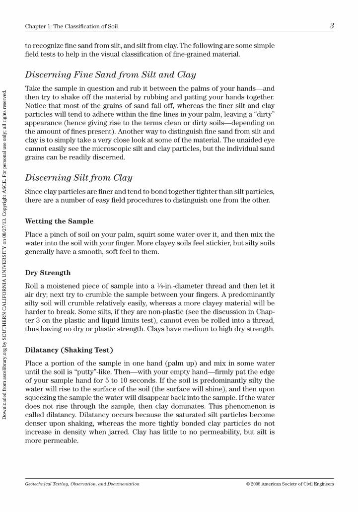
to recognize fine sand from silt, and silt from clay. the following are some simple field tests to help in the visual classification of fine-grained material.
Discerning Fine Sand from Silt and Clay
take the sample in question and rub it between the palms of your hands—and then try to shake off the material by rubbing and patting your hands together. notice that most of the grains of sand fall off, whereas the finer silt and clay particles will tend to adhere within the fine lines in your palm, leaving a “dirty” appearance (hence giving rise to the terms clean or dirty soils—depending on the amount of fines present). Another way to distinguish fine sand from silt and clay is to simply take a very close look at some of the material. the unaided eye cannot easily see the microscopic silt and clay particles, but the individual sand grains can be readily discerned.
Discerning Silt from Clay
Since clay particles are finer and tend to bond together tighter than silt particles, there are a number of easy field procedures to distinguish one from the other.
Wetting the Sample
Place a pinch of soil on your palm, squirt some water over it, and then mix the water into the soil with your finger. more clayey soils feel stickier, but silty soils generally have a smooth, soft feel to them.
Dry Strength
roll a moistened piece of sample into a 1⁄8-in.-diameter thread and then let it air dry; next try to crumble the sample between your fingers. A predominantly silty soil will crumble relatively easily, whereas a more clayey material will be harder to break. Some silts, if they are non-plastic (see the discussion in chap-ter 3 on the plastic and liquid limits test), cannot even be rolled into a thread, thus having no dry or plastic strength. clays have medium to high dry strength.
Dilatancy (Shaking Test)
Place a portion of the sample in one hand (palm up) and mix in some water until the soil is “putty”-like. then—with your empty hand—firmly pat the edge of your sample hand for 5 to 10 seconds. if the soil is predominantly silty the water will rise to the surface of the soil (the surface will shine), and then upon squeezing the sample the water will disappear back into the sample. if the water does not rise through the sample, then clay dominates. this phenomenon is called dilatancy. Dilatancy occurs because the saturated silt particles become denser upon shaking, whereas the more tightly bonded clay particles do not increase in density when jarred. clay has little to no permeability, but silt is more permeable.
Dow
nloa
ded
from
asc
elib
rary
.org
by
SOU
TH
ER
N C
AL
IFO
RN
IA U
NIV
ER
SIT
Y o
n 08
/27/
13. C
opyr
ight
ASC
E. F
or p
erso
nal u
se o
nly;
all
righ
ts r
eser
ved.
Geotechnical Testing, Observation, and Documentation © 2008 American Society of civil Engineers
4 chapter 1: the classification of Soil
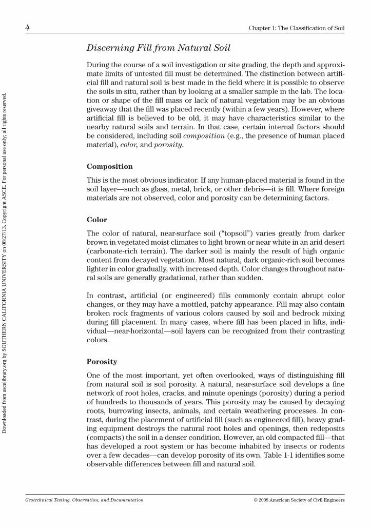
Discerning Fill from Natural Soil
During the course of a soil investigation or site grading, the depth and approxi-mate limits of untested fill must be determined. the distinction between artifi-cial fill and natural soil is best made in the field where it is possible to observe the soils in situ, rather than by looking at a smaller sample in the lab. the loca-tion or shape of the fill mass or lack of natural vegetation may be an obvious giveaway that the fill was placed recently (within a few years). however, where artificial fill is believed to be old, it may have characteristics similar to the nearby natural soils and terrain. in that case, certain internal factors should be considered, including soil composition (e.g., the presence of human placed material), color, and porosity.
Composition
this is the most obvious indicator. if any human-placed material is found in the soil layer—such as glass, metal, brick, or other debris—it is fill. Where foreign materials are not observed, color and porosity can be determining factors.
Color
the color of natural, near-surface soil (“topsoil”) varies greatly from darker brown in vegetated moist climates to light brown or near white in an arid desert (carbonate-rich terrain). the darker soil is mainly the result of high organic content from decayed vegetation. most natural, dark organic-rich soil becomes lighter in color gradually, with increased depth. color changes throughout natu-ral soils are generally gradational, rather than sudden.
in contrast, artificial (or engineered) fills commonly contain abrupt color changes, or they may have a mottled, patchy appearance. Fill may also contain broken rock fragments of various colors caused by soil and bedrock mixing during fill placement. in many cases, where fill has been placed in lifts, indi-vidual—near-horizontal—soil layers can be recognized from their contrasting colors.
Porosity
one of the most important, yet often overlooked, ways of distinguishing fill from natural soil is soil porosity. A natural, near-surface soil develops a fine network of root holes, cracks, and minute openings (porosity) during a period of hundreds to thousands of years. this porosity may be caused by decaying roots, burrowing insects, animals, and certain weathering processes. in con-trast, during the placement of artificial fill (such as engineered fill), heavy grad-ing equipment destroys the natural root holes and openings, then redeposits (compacts) the soil in a denser condition. however, an old compacted fill—that has developed a root system or has become inhabited by insects or rodents over a few decades—can develop porosity of its own. table 1-1 identifies some observable differences between fill and natural soil.
Dow
nloa
ded
from
asc
elib
rary
.org
by
SOU
TH
ER
N C
AL
IFO
RN
IA U
NIV
ER
SIT
Y o
n 08
/27/
13. C
opyr
ight
ASC
E. F
or p
erso
nal u
se o
nly;
all
righ
ts r
eser
ved.
Geotechnical Testing, Observation, and Documentation © 2008 American Society of civil Engineers
chapter 1: the classification of Soil 5
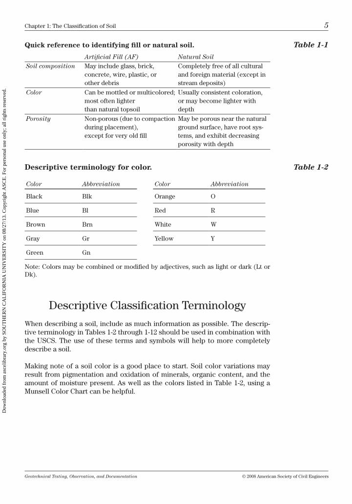
Descriptive classification terminology
When describing a soil, include as much information as possible. the descrip-tive terminology in tables 1-2 through 1-12 should be used in combination with the uScS. the use of these terms and symbols will help to more completely describe a soil.
making note of a soil color is a good place to start. Soil color variations may result from pigmentation and oxidation of minerals, organic content, and the amount of moisture present. As well as the colors listed in table 1-2, using a munsell color chart can be helpful.
Descriptive terminology for color. Table 1-2
Quick reference to identifying fill or natural soil. Table 1-1
Artificial Fill (AF) Natural Soil
Soil composition may include glass, brick, concrete, wire, plastic, or other debris
completely free of all cultural and foreign material (except in stream deposits)
Color can be mottled or multi colored; most often lighter than natural topsoil
usually consistent coloration, or may become lighter with depth
Porosity non-porous (due to com paction during placement), except for very old fill
may be porous near the natural ground surface, have root sys-tems, and exhibit decreasing porosity with depth
note: colors may be combined or modified by adjectives, such as light or dark (lt or Dk).
Color Abbreviation
black blk
blue bl
brown brn
Gray Gr
Green Gn
Color Abbreviation
orange o
red r
White W
yellow y
Dow
nloa
ded
from
asc
elib
rary
.org
by
SOU
TH
ER
N C
AL
IFO
RN
IA U
NIV
ER
SIT
Y o
n 08
/27/
13. C
opyr
ight
ASC
E. F
or p
erso
nal u
se o
nly;
all
righ
ts r
eser
ved.
Geotechnical Testing, Observation, and Documentation © 2008 American Society of civil Engineers
6 chapter 1: the classification of Soil
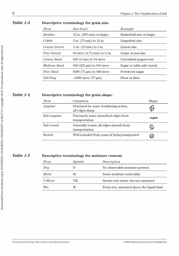
Table 1-3 Descriptive terminology for grain size.
Term Size limit Example
Boulder 12 in. (305 mm) or larger basketball size or larger
Cobble 3 in. (75 mm) to 12 in. Grapefruit size
Coarse Gravel ¾ in. (19 mm) to 3 in. lemon size
Fine Gravel #4 sieve (4.75 mm) to ¾ in. Grape or pea size
Coarse Sand #10 (2 mm) to #4 sieve uncrushed peppercorn
Medium Sand #40 (425 µm) to #10 sieve Sugar or table salt crystal
Fine Sand #200 (75 µm) to #40 sieve Powdered sugar
Silt/Clay <#200 sieve (75 µm) Flour or finer
Table 1-4 Descriptive terminology for grain shape.
Term Causation Shape
Angular Fractured by some weathering action, all edges sharp
Sub-angular Fractured, some smoothed edges from transportation
Sub-round Generally round, all edges smooth from transportation
Round Well-rounded from years of being transported
Table 1-5 Descriptive terminology for moisture content.
Term Symbol Description
Dry D no observable moisture present
Moist m Some moisture noticeable
V Moist vm Seems very moist, but not saturated
Wet W Feels wet, saturated above the liquid limit
Dow
nloa
ded
from
asc
elib
rary
.org
by
SOU
TH
ER
N C
AL
IFO
RN
IA U
NIV
ER
SIT
Y o
n 08
/27/
13. C
opyr
ight
ASC
E. F
or p
erso
nal u
se o
nly;
all
righ
ts r
eser
ved.
Geotechnical Testing, Observation, and Documentation © 2008 American Society of civil Engineers
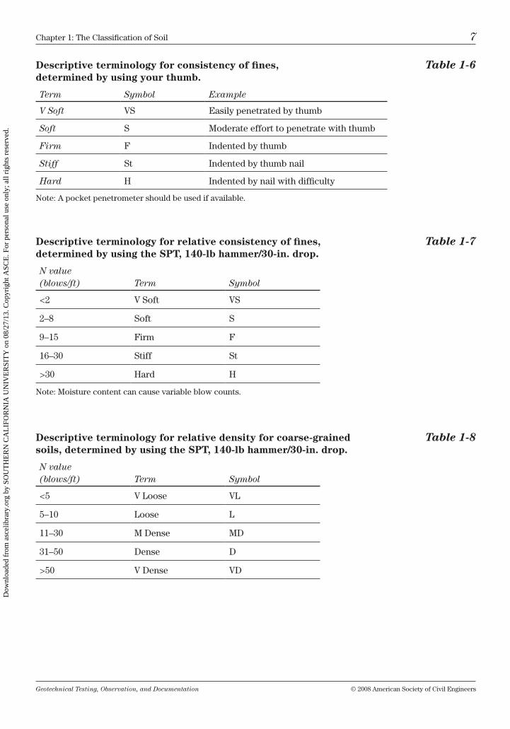
chapter 1: the classification of Soil 7
Descriptive terminology for consistency of fines, Table 1-6 determined by using your thumb.
Term Symbol Example
V Soft vS Easily penetrated by thumb
Soft S moderate effort to penetrate with thumb
Firm F indented by thumb
Stiff St indented by thumb nail
Hard h indented by nail with difficulty
note: A pocket penetrometer should be used if available.
Descriptive terminology for relative consistency of fines, Table 1-7 determined by using the SPT, 140-lb hammer/30-in. drop.
N value (blows/ft) Term Symbol
<2 v Soft vS
2–8 Soft S
9–15 Firm F
16–30 Stiff St
>30 hard h
note: moisture content can cause variable blow counts.
Descriptive terminology for relative density for coarse-grained Table 1-8 soils, determined by using the SPT, 140-lb hammer/30-in. drop.
N value (blows/ft) Term Symbol
<5 v loose vl
5–10 loose l
11–30 m Dense mD
31–50 Dense D
>50 v Dense vD
Dow
nloa
ded
from
asc
elib
rary
.org
by
SOU
TH
ER
N C
AL
IFO
RN
IA U
NIV
ER
SIT
Y o
n 08
/27/
13. C
opyr
ight
ASC
E. F
or p
erso
nal u
se o
nly;
all
righ
ts r
eser
ved.
Geotechnical Testing, Observation, and Documentation © 2008 American Society of civil Engineers
8 chapter 1: the classification of Soil
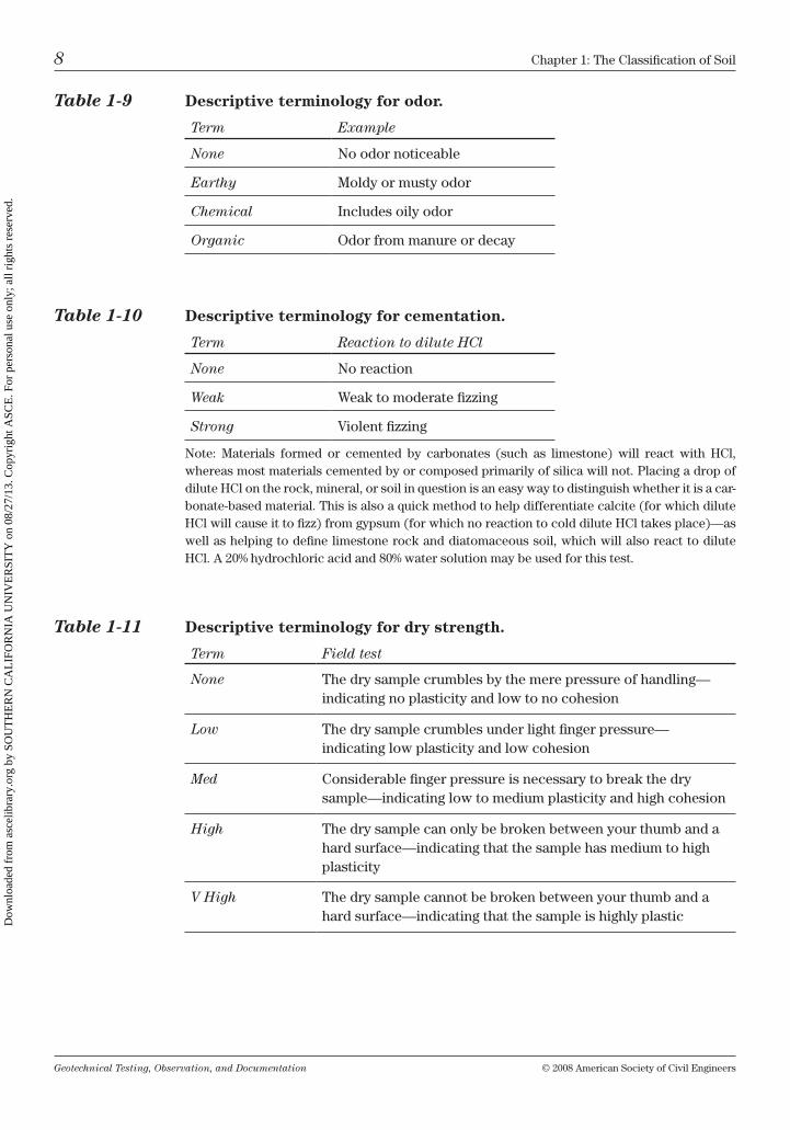
Table 1-11 Descriptive terminology for dry strength.
Term Field test
None the dry sample crumbles by the mere pressure of handling—indicating no plasticity and low to no cohesion
Low the dry sample crumbles under light finger pressure— indicating low plasticity and low cohesion
Med considerable finger pressure is necessary to break the dry sample—indicating low to medium plasticity and high cohesion
High the dry sample can only be broken between your thumb and a hard surface—indicating that the sample has medium to high plasticity
V High the dry sample cannot be broken between your thumb and a hard surface—indicating that the sample is highly plastic
Table 1-9 Descriptive terminology for odor.
Term Example
None no odor noticeable
Earthy moldy or musty odor
Chemical includes oily odor
Organic odor from manure or decay
Table 1-10 Descriptive terminology for cementation.
Term Reaction to dilute HCl
None no reaction
Weak Weak to moderate fizzing
Strong violent fizzing
note: materials formed or cemented by carbonates (such as limestone) will react with hcl, whereas most materials cemented by or composed primarily of silica will not. Placing a drop of dilute hcl on the rock, mineral, or soil in question is an easy way to distinguish whether it is a car-bonate-based material. this is also a quick method to help differentiate calcite (for which dilute hcl will cause it to fizz) from gypsum (for which no reaction to cold dilute hcl takes place)—as well as helping to define limestone rock and diatomaceous soil, which will also react to dilute hcl. A 20% hydrochloric acid and 80% water solution may be used for this test.
Dow
nloa
ded
from
asc
elib
rary
.org
by
SOU
TH
ER
N C
AL
IFO
RN
IA U
NIV
ER
SIT
Y o
n 08
/27/
13. C
opyr
ight
ASC
E. F
or p
erso
nal u
se o
nly;
all
righ
ts r
eser
ved.
Geotechnical Testing, Observation, and Documentation © 2008 American Society of civil Engineers
chapter 1: the classification of Soil 9
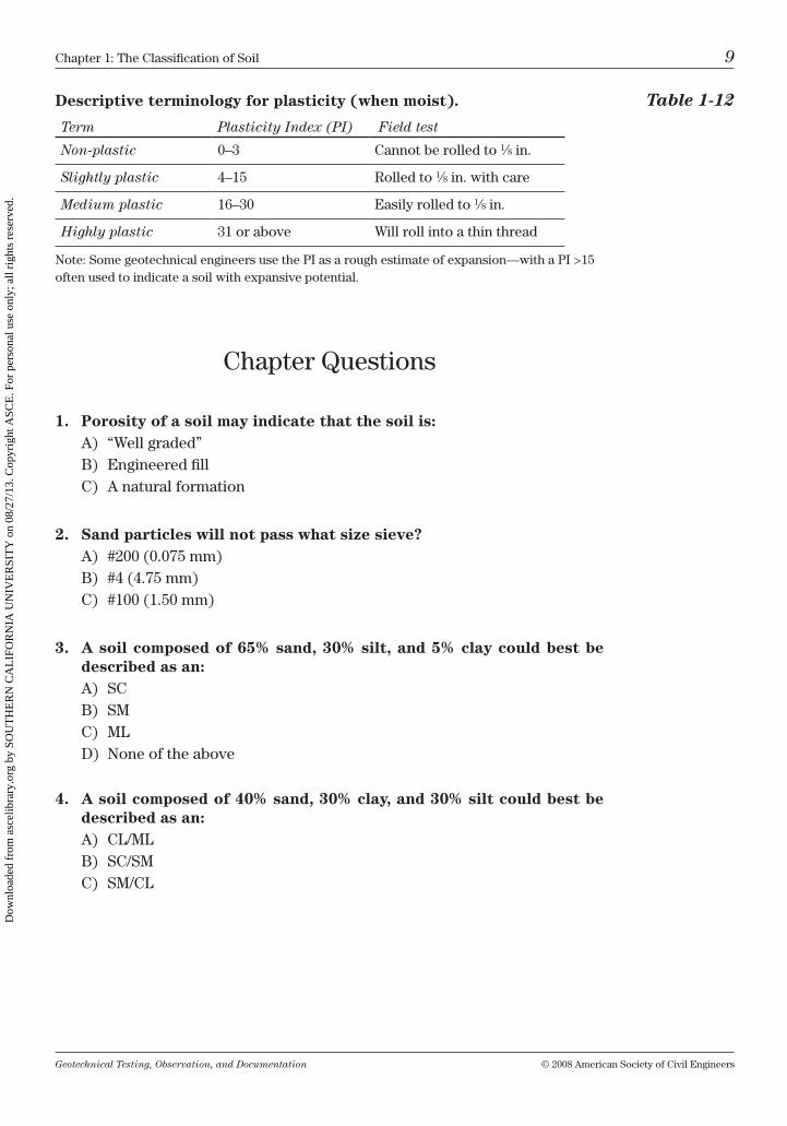
chapter Questions
1. Porosity of a soil may indicate that the soil is:A) “Well graded”b) Engineered fillc) A natural formation
2. Sand particles will not pass what size sieve?A) #200 (0.075 mm)b) #4 (4.75 mm)c) #100 (1.50 mm)
3. A soil composed of 65% sand, 30% silt, and 5% clay could best be described as an:A) Scb) Smc) mlD) none of the above
4. A soil composed of 40% sand, 30% clay, and 30% silt could best be described as an:A) cl/mlb) Sc/Smc) Sm/cl
Descriptive terminology for plasticity (when moist). Table 1-12
Term Plasticity Index (PI) Field test
Non-plastic 0–3 cannot be rolled to 1⁄8 in.
Slightly plastic 4–15 rolled to 1⁄8 in. with care
Medium plastic 16–30 Easily rolled to 1⁄8 in.
Highly plastic 31 or above Will roll into a thin thread
note: Some geotechnical engineers use the Pi as a rough estimate of expansion—with a Pi >15 often used to indicate a soil with expansive potential.
Dow
nloa
ded
from
asc
elib
rary
.org
by
SOU
TH
ER
N C
AL
IFO
RN
IA U
NIV
ER
SIT
Y o
n 08
/27/
13. C
opyr
ight
ASC
E. F
or p
erso
nal u
se o
nly;
all
righ
ts r
eser
ved.
Geotechnical Testing, Observation, and Documentation © 2008 American Society of civil Engineers
10 chapter 1: the classification of Soil
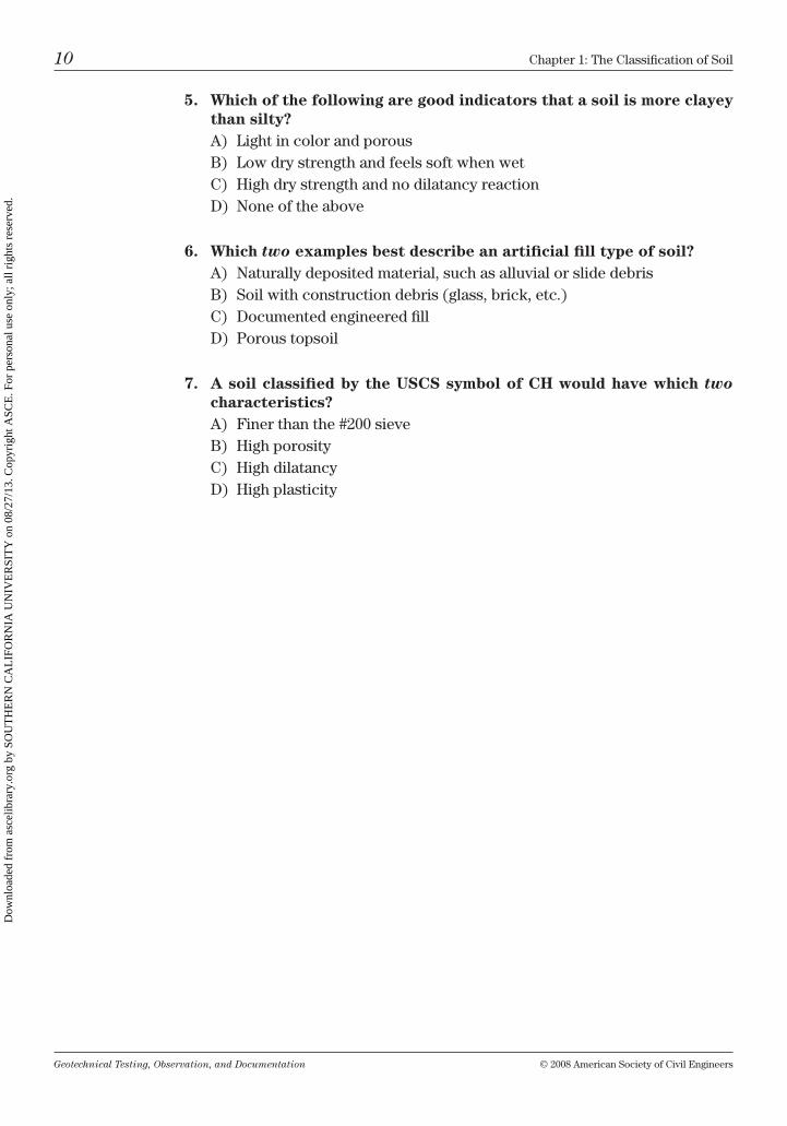
5. Which of the following are good indicators that a soil is more clayey than silty?A) light in color and porousb) low dry strength and feels soft when wetc) high dry strength and no dilatancy reactionD) none of the above
6. Which two examples best describe an artificial fill type of soil?A) naturally deposited material, such as alluvial or slide debrisb) Soil with construction debris (glass, brick, etc.)c) Documented engineered fillD) Porous topsoil
7. A soil classified by the USCS symbol of CH would have which two characteristics?A) Finer than the #200 sieveb) high porosityc) high dilatancyD) high plasticity
Dow
nloa
ded
from
asc
elib
rary
.org
by
SOU
TH
ER
N C
AL
IFO
RN
IA U
NIV
ER
SIT
Y o
n 08
/27/
13. C
opyr
ight
ASC
E. F
or p
erso
nal u
se o
nly;
all
righ
ts r
eser
ved.
Geotechnical Testing, Observation, and Documentation © 2008 American Society of civil Engineers 11
2Exploration Techniques and Sampling Methods
before grading on a project can begin, it is necessary to perform a site explora-tion to determine site soil conditions. this exploration provides information for an engineering and geologic report (geotechnical report) describing surface and subsurface conditions.
upon review of the existing surface conditions—and considering the proposed cuts and fills, structures, and the general types of soils expected to be encoun-tered—the project manager can decide what type of sampling method(s) may best suit the site. before any type of drilling or trenching takes place, all existing underground utilities must be located! All utilities can usually be contacted via a statewide phone number and a locating service will be dispatched.
to help compile information for the geotechnical investigation, an experienced technician, engineer, or geologist is sent to the area to help document site con-ditions. During the investigation, a general site plan should be drawn up that includes locations of surface features such as trees, washes, streams, slopes, old fills (stockpiles of material or debris), old pavements or structures (foot-ings, slabs, etc.), and any other features that may influence the design or grad-ing process.
backhoe trenches
Excavating a number of trenches with a backhoe (or a larger excavator) is one method of securing soil samples, as well as an excellent way to observe subsur-face site conditions. trench excavations may be especially helpful to the geolo-gist in viewing bedding, slide planes, seeps, faulting, the condition of in-place bedrock, and other features of geologic concern. better views of old fill and/or debris can be seen along the larger exposed trench walls, as opposed to a smaller downhole sample.
the relative ease with which a trench can be dug is also valuable information. if the soils are tightly cemented or bedrock is encountered, the hardness of exca-vation or depth to refusal is valuable information for the grading contractor in determining excavatability. Such information may help determine the need
Dow
nloa
ded
from
asc
elib
rary
.org
by
SOU
TH
ER
N C
AL
IFO
RN
IA U
NIV
ER
SIT
Y o
n 08
/27/
13. C
opyr
ight
ASC
E. F
or p
erso
nal u
se o
nly;
all
righ
ts r
eser
ved.
Geotechnical Testing, Observation, and Documentation © 2008 American Society of civil Engineers
12 chapter 2: Exploration techniques and Sampling methods
to use a large dozer to rip through hard material, or even the blasting of the soil or rock formation to sufficiently loosen or break down the material for excavation.
As the exploration trench is dug, level steps may be excavated at desired eleva-tions to allow for in-place density tests. Remember to always follow trench safety guidelines (per OSHA). bag samples can be obtained as needed, usu-ally at each significant soil change. the job name, project number, date, trench number, sample depth/elevation, and visual soil classification should be included on the label of each bag.
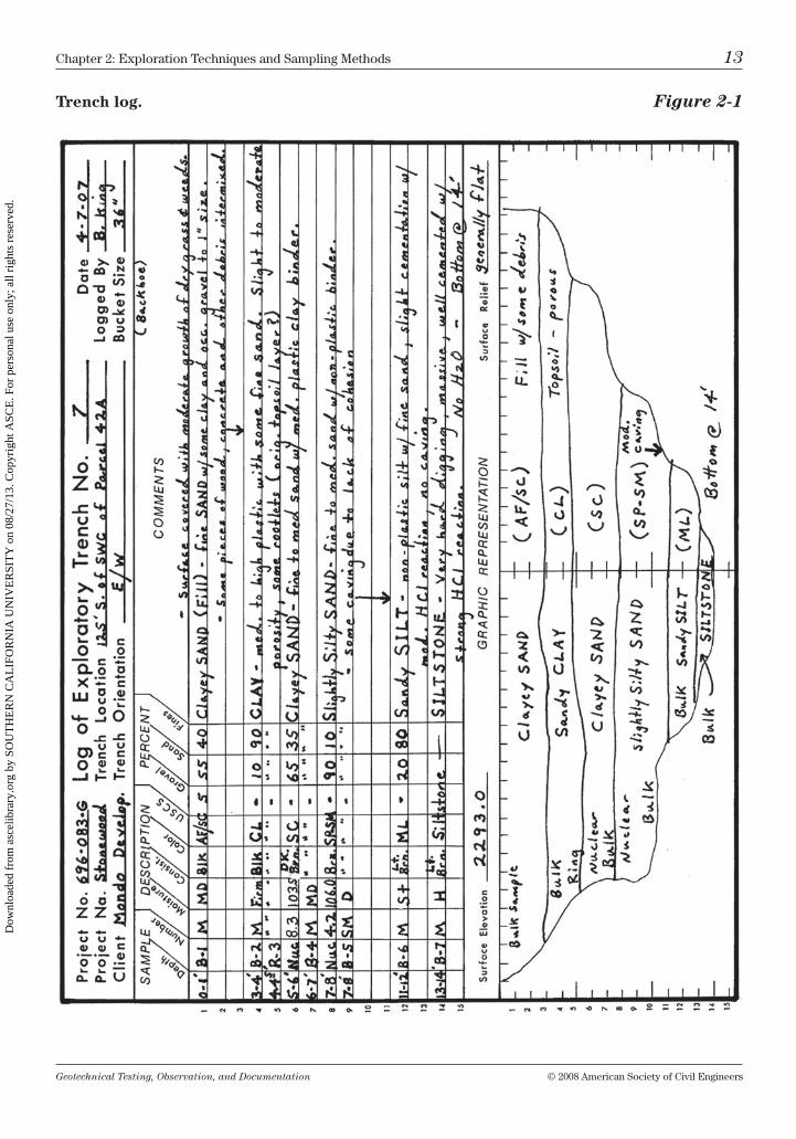
An accurate trench log must be kept. Figure 2-1 presents a graphic representa-tion of a trench log. Quite often, the graphic profile of subsurface conditions is the most valuable information retained on a project, allowing for a quick view of subsurface conditions at a future date.
Along with soil descriptions, it is important to indicate on the log whether any caving or sloughing occurred during excavation, and at what depths. record the depth of any water encountered, and its source when possible (groundwa-ter, seep, etc.). Also, try to determine the approximate flow rate of the water.
Draw your own plot plan if one does not exist. be sure to “tie in” the site loca-tion with a relatively permanent marker, such as a curb, telephone pole, build-ing, wash, or even trees. remember to note trench direction and length. include a north arrow and note the scale of your drawing.
rock Excavation Study (rippability)
often an investigation is performed to help determine the hardness (excavat-ability) of subsurface rock or cemented formations. this information is then used by the grading contractor to help determine the best methods for remov-ing the hard material. methods of removal may include hydro-hammers, rock saws, heavy dozers using a single shank (ripper), or blasting.
one of the simplest rippability investigations is the geophysical seismic refrac-tion survey, in which a number of seismic traverses (seismic lines) are laid out, with the length of each line dependent on the depth necessary to perform a proper evaluation. typically, the effective depth of evaluation is approximately one-third to one-fifth the length of the seismic line. Geophones are placed at intervals and are connected by electrical wire to establish the line. commonly, a metal plate is placed on the ground at one end of the seismic line; the plate is struck by a sledge hammer to generate seismic waves at the surface. these waves are refracted beneath the surface by materials of varying densities (hard-ness), thus creating contrasting velocities. the refracted seismic waves are then detected by the geophones, which send the velocity times to the seismograph for recording. Since seismic waves generally travel faster through harder for-mations, a higher velocity usually indicates harder rock.
Dow
nloa
ded
from
asc
elib
rary
.org
by
SOU
TH
ER
N C
AL
IFO
RN
IA U
NIV
ER
SIT
Y o
n 08
/27/
13. C
opyr
ight
ASC
E. F
or p
erso
nal u
se o
nly;
all
righ
ts r
eser
ved.
Geotechnical Testing, Observation, and Documentation © 2008 American Society of civil Engineers
chapter 2: Exploration techniques and Sampling methods 13
Trench log. Figure 2-1
Dow
nloa
ded
from
asc
elib
rary
.org
by
SOU
TH
ER
N C
AL
IFO
RN
IA U
NIV
ER
SIT
Y o
n 08
/27/
13. C
opyr
ight
ASC
E. F
or p
erso
nal u
se o
nly;
all
righ
ts r
eser
ved.
Geotechnical Testing, Observation, and Documentation © 2008 American Society of civil Engineers
14 chapter 2: Exploration techniques and Sampling methods
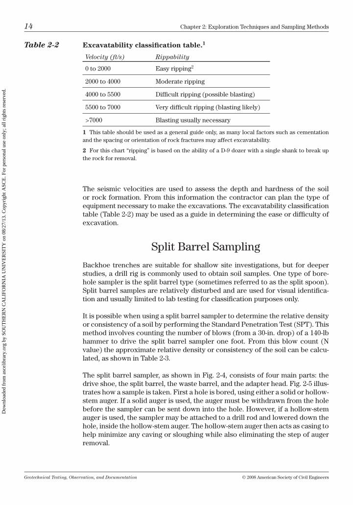
the seismic velocities are used to assess the depth and hardness of the soil or rock formation. From this information the contractor can plan the type of equipment necessary to make the excavations. the excavatability classification table (table 2-2) may be used as a guide in determining the ease or difficulty of excavation.
Split barrel Sampling
backhoe trenches are suitable for shallow site investigations, but for deeper studies, a drill rig is commonly used to obtain soil samples. one type of bore-hole sampler is the split barrel type (sometimes referred to as the split spoon). Split barrel samples are relatively disturbed and are used for visual identifica-tion and usually limited to lab testing for classification purposes only.
it is possible when using a split barrel sampler to determine the relative density or consistency of a soil by performing the Standard Penetration test (SPt). this method involves counting the number of blows (from a 30-in. drop) of a 140-lb hammer to drive the split barrel sampler one foot. From this blow count (n value) the approximate relative density or consistency of the soil can be calcu-lated, as shown in table 2-3.
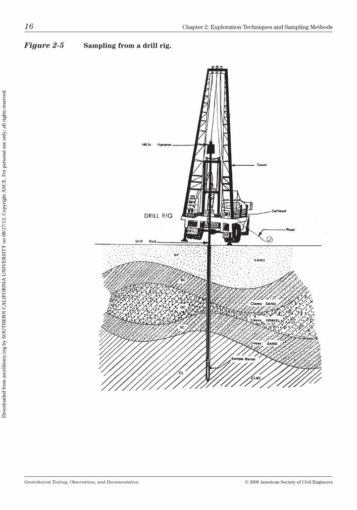
the split barrel sampler, as shown in Fig. 2-4, consists of four main parts: the drive shoe, the split barrel, the waste barrel, and the adapter head. Fig. 2-5 illus-trates how a sample is taken. First a hole is bored, using either a solid or hollow-stem auger. if a solid auger is used, the auger must be withdrawn from the hole before the sampler can be sent down into the hole. however, if a hollow-stem auger is used, the sampler may be attached to a drill rod and lowered down the hole, inside the hollow-stem auger. the hollow-stem auger then acts as casing to help minimize any caving or sloughing while also eliminating the step of auger removal.
Table 2-2 Excavatability classification table.1
Velocity (ft/s) Rippability
0 to 2000 Easy ripping2
2000 to 4000 moderate ripping
4000 to 5500 Difficult ripping (possible blasting)
5500 to 7000 very difficult ripping (blasting likely)
>7000 blasting usually necessary
1 this table should be used as a general guide only, as many local factors such as cementation and the spacing or orientation of rock fractures may affect excavatability.
2 For this chart “ripping” is based on the ability of a D-9 dozer with a single shank to break up the rock for removal.
Dow
nloa
ded
from
asc
elib
rary
.org
by
SOU
TH
ER
N C
AL
IFO
RN
IA U
NIV
ER
SIT
Y o
n 08
/27/
13. C
opyr
ight
ASC
E. F
or p
erso
nal u
se o
nly;
all
righ
ts r
eser
ved.
Geotechnical Testing, Observation, and Documentation © 2008 American Society of civil Engineers
chapter 2: Exploration techniques and Sampling methods 15
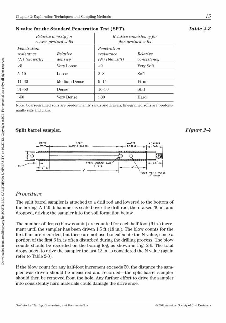
N value for the Standard Penetration Test (SPT). Table 2-3
Relative density for coarse-grained soils
Relative consistency for fine-grained soils
Penetration resistance (N) (blows/ft)
Relative density
Penetration resistance (N) (blows/ft)
Relative consistency
<5 very loose <2 very Soft
5–10 loose 2–8 Soft
11–30 medium Dense 9–15 Firm
31–50 Dense 16–30 Stiff
>50 very Dense >30 hard
note: coarse-grained soils are predominantly sands and gravels; fine-grained soils are predomi-nantly silts and clays.
Split barrel sampler. Figure 2-4
Procedurethe split barrel sampler is attached to a drill rod and lowered to the bottom of the boring. A 140-lb hammer is seated over the drill rod, then raised 30 in. and dropped, driving the sampler into the soil formation below.
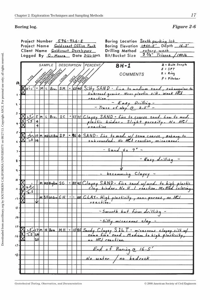
the number of drops (blow counts) are counted for each half-foot (6 in.) incre-ment until the sampler has been driven 1.5 ft (18 in.). the blow counts for the first 6 in. are recorded, but these are not used to calculate the n value, since a portion of the first 6 in. is often disturbed during the drilling process. the blow counts should be recorded on the boring log, as shown in Fig. 2-6. the total drops taken to drive the sampler the last 12 in. is considered the n value (again refer to table 2-3).
if the blow count for any half-foot increment exceeds 50, the distance the sam-pler was driven should be measured and recorded—the split barrel sampler should then be removed from the hole. Any further effort to drive the sampler into consistently hard materials could damage the drive shoe.
Dow
nloa
ded
from
asc
elib
rary
.org
by
SOU
TH
ER
N C
AL
IFO
RN
IA U
NIV
ER
SIT
Y o
n 08
/27/
13. C
opyr
ight
ASC
E. F
or p
erso
nal u
se o
nly;
all
righ
ts r
eser
ved.
Geotechnical Testing, Observation, and Documentation © 2008 American Society of civil Engineers
16 chapter 2: Exploration techniques and Sampling methods
Figure 2-5 Sampling from a drill rig.
Dow
nloa
ded
from
asc
elib
rary
.org
by
SOU
TH
ER
N C
AL
IFO
RN
IA U
NIV
ER
SIT
Y o
n 08
/27/
13. C
opyr
ight
ASC
E. F
or p
erso
nal u
se o
nly;
all
righ
ts r
eser
ved.
Geotechnical Testing, Observation, and Documentation © 2008 American Society of civil Engineers
chapter 2: Exploration techniques and Sampling methods 17
Boring log. Figure 2-6
Dow
nloa
ded
from
asc
elib
rary
.org
by
SOU
TH
ER
N C
AL
IFO
RN
IA U
NIV
ER
SIT
Y o
n 08
/27/
13. C
opyr
ight
ASC
E. F
or p
erso
nal u
se o
nly;
all
righ
ts r
eser
ved.
Geotechnical Testing, Observation, and Documentation © 2008 American Society of civil Engineers
18 chapter 2: Exploration techniques and Sampling methods
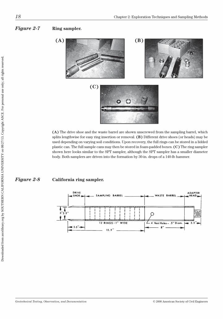
Figure 2-7 Ring sampler.
(A) the drive shoe and the waste barrel are shown unscrewed from the sampling barrel, which splits lengthwise for easy ring insertion or removal. (B) Different drive shoes (or heads) may be used depending on varying soil conditions. upon recovery, the full rings can be stored in a lidded plastic can. the full sample cans may then be stored in foam-padded boxes. (C) the ring sampler shown here looks similar to the SPt sampler, although the SPt sampler has a smaller diameter body. both samplers are driven into the formation by 30-in. drops of a 140-lb hammer.
(A) (B)
(C)
Figure 2-8 California ring sampler.
Dow
nloa
ded
from
asc
elib
rary
.org
by
SOU
TH
ER
N C
AL
IFO
RN
IA U
NIV
ER
SIT
Y o
n 08
/27/
13. C
opyr
ight
ASC
E. F
or p
erso
nal u
se o
nly;
all
righ
ts r
eser
ved.
Geotechnical Testing, Observation, and Documentation © 2008 American Society of civil Engineers
chapter 2: Exploration techniques and Sampling methods 19
Tip: if the material being sampled is predominantly noncohesive (such as clean sand), the soil may have a tendency to slip out of the sampler as the barrel is raised from the hole. under these conditions it may then be necessary to install a “sample grabber” between the drive shoe and the sample barrel to help keep any material from slipping out during sample recovery. the sample grabber allows the sandy soil to pass up into the sample barrel but closes up as the barrel is being removed.
After the sampler is disconnected from the rod, the drive shoe and waste barrel are unscrewed from the sample barrel. the sample barrel is then opened along the split (lengthwise). the length of the sample should be measured—and then recorded on the log—as the amount of recovery. Finally, the sample should be visually classified, sealed in a plastic bag or jar, and then labeled prior to trans-porting it to the lab.
Tip: Experience has shown that it is wise to use an indelible black marker to label directly onto the sample bag; this will help to eliminate losing information when samples arrive back at the lab with wired tags broken off, or with stick-on tags missing!
Sampling with rings
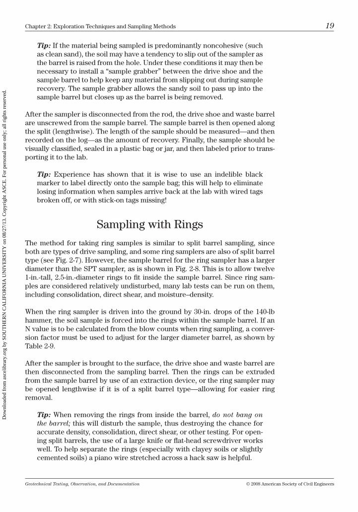
the method for taking ring samples is similar to split barrel sampling, since both are types of drive sampling, and some ring samplers are also of split barrel type (see Fig. 2-7). however, the sample barrel for the ring sampler has a larger diameter than the SPt sampler, as is shown in Fig. 2-8. this is to allow twelve 1-in.-tall, 2.5-in.-diameter rings to fit inside the sample barrel. Since ring sam-ples are considered relatively undisturbed, many lab tests can be run on them, including consolidation, direct shear, and moisture–density.
When the ring sampler is driven into the ground by 30-in. drops of the 140-lb hammer, the soil sample is forced into the rings within the sample barrel. if an n value is to be calculated from the blow counts when ring sampling, a conver-sion factor must be used to adjust for the larger diameter barrel, as shown by table 2-9.
After the sampler is brought to the surface, the drive shoe and waste barrel are then disconnected from the sampling barrel. then the rings can be extruded from the sample barrel by use of an extraction device, or the ring sampler may be opened lengthwise if it is of a split barrel type—allowing for easier ring removal.
Tip: When removing the rings from inside the barrel, do not bang on the barrel; this will disturb the sample, thus destroying the chance for accurate density, consolidation, direct shear, or other testing. For open-ing split barrels, the use of a large knife or flat-head screwdriver works well. to help separate the rings (especially with clayey soils or slightly cemented soils) a piano wire stretched across a hack saw is helpful.
Dow
nloa
ded
from
asc
elib
rary
.org
by
SOU
TH
ER
N C
AL
IFO
RN
IA U
NIV
ER
SIT
Y o
n 08
/27/
13. C
opyr
ight
ASC
E. F
or p
erso
nal u
se o
nly;
all
righ
ts r
eser
ved.
Geotechnical Testing, Observation, and Documentation © 2008 American Society of civil Engineers
20 chapter 2: Exploration techniques and Sampling methods
After the rings from the sampler are carefully removed, they can be slid into a plastic bag, then placed inside a plastic can, and finally sealed airtight. the can should be labeled on top with appropriate information, such as borehole, soil type, sample number, depth of sample, project number, and the like.
thin-Walled tube Sampling
tube sampling will disturb the sample less than drive sampling methods. tube samples may be used for all types of testing, from basic classification tests to more involved testing, such as triaxial tests. tube sampling is known as “thin-walled sampling” or by brand names such as Pitcher™ and Shelby™.
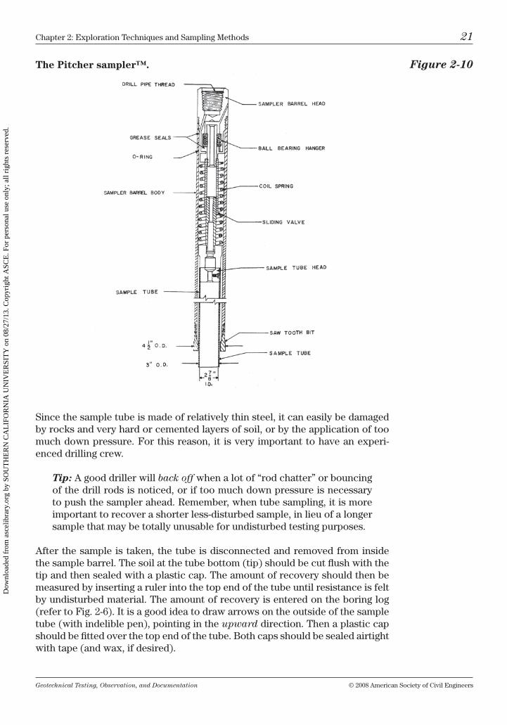
tube sampling is commonly performed from a rotary drill rig by using air or drill mud to keep the boring clear of cuttings and to stabilize the borehole walls. A Pitcher™-type sample tube is typically 3 ft in length, with a 3-in. outside diam-eter (o.D.) and an approximately 2 7⁄8-in. inner diameter (i.D.). the tube is slid up inside a sample barrel. the Pitcher™ sample barrel is equipped with a saw-tooth bit at the leading end (see Fig. 2-10) and is spring-loaded to help keep even down pressure at the tip of the tube while sampling.
Procedure
the sample barrel is connected to a drill rod and lowered to the bottom of the hole. While the teeth of the sample barrel slowly cut a hole around the tube, the tube is pushed into the soil formation by a steady downward pressure. the sample tube should always lead the sample barrel, helping to ensure an undis-turbed sample.
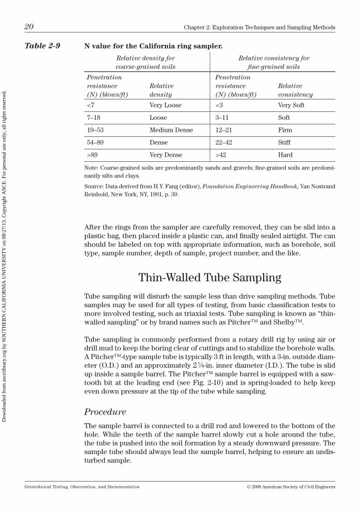
Table 2-9 N value for the California ring sampler.
Relative density for coarse-grained soils
Relative consistency for fine-grained soils
Penetration resistance (N) (blows/ft)
Relative density
Penetration resistance (N) (blows/ft)
Relative consistency
<7 very loose <3 very Soft
7–18 loose 3–11 Soft
19–53 medium Dense 12–21 Firm
54–89 Dense 22–42 Stiff
>89 very Dense >42 hard
note: coarse-grained soils are predominantly sands and gravels; fine-grained soils are predomi-nantly silts and clays.
Source: Data derived from h.y. Fang (editor), Foundation Engineering Handbook, van nostrand reinhold, new york, ny, 1991, p. 39.
Dow
nloa
ded
from
asc
elib
rary
.org
by
SOU
TH
ER
N C
AL
IFO
RN
IA U
NIV
ER
SIT
Y o
n 08
/27/
13. C
opyr
ight
ASC
E. F
or p
erso
nal u
se o
nly;
all
righ
ts r
eser
ved.
Geotechnical Testing, Observation, and Documentation © 2008 American Society of civil Engineers
chapter 2: Exploration techniques and Sampling methods 21
Since the sample tube is made of relatively thin steel, it can easily be damaged by rocks and very hard or cemented layers of soil, or by the application of too much down pressure. For this reason, it is very important to have an experi-enced drilling crew.
Tip: A good driller will back off when a lot of “rod chatter” or bouncing of the drill rods is noticed, or if too much down pressure is necessary to push the sampler ahead. remember, when tube sampling, it is more important to recover a shorter less-disturbed sample, in lieu of a longer sample that may be totally unusable for undisturbed testing purposes.
After the sample is taken, the tube is disconnected and removed from inside the sample barrel. the soil at the tube bottom (tip) should be cut flush with the tip and then sealed with a plastic cap. the amount of recovery should then be measured by inserting a ruler into the top end of the tube until resistance is felt by undisturbed material. the amount of recovery is entered on the boring log (refer to Fig. 2-6). it is a good idea to draw arrows on the outside of the sample tube (with indelible pen), pointing in the upward direction. then a plastic cap should be fitted over the top end of the tube. both caps should be sealed airtight with tape (and wax, if desired).
The Pitcher sampler™. Figure 2-10
Dow
nloa
ded
from
asc
elib
rary
.org
by
SOU
TH
ER
N C
AL
IFO
RN
IA U
NIV
ER
SIT
Y o
n 08
/27/
13. C
opyr
ight
ASC
E. F
or p
erso
nal u
se o
nly;
all
righ
ts r
eser
ved.
Geotechnical Testing, Observation, and Documentation © 2008 American Society of civil Engineers
22 chapter 2: Exploration techniques and Sampling methods
When moving these samples to the lab, they should be placed in well-padded containers and transported carefully in the “upward” position. this will help to minimize any disturbance during transport. once at the lab, the tubes can be cut with a tube cutter to the desired length. care should be taken while cutting the metal tube not to apply too much pressure, which would cause the barrel to become “egg shaped.” the sample may then be carefully pushed out of the tube with an extruding device.
care should be taken to record all information onto the log sheet. A complete log sheet should include the following data:
• avisualsoildescriptionateachobservablematerialchange,includingusingthe uScS;
• estimationofdensityandconsistencyofsoil;
• easeofdrillingordigging(downpressure,rodchatter,refusal,etc.);
• ifwaterisencountered,itslevelandapproximateflowrate;
• anoteofanycavingorsloughing;
• thedepthor thicknessofanyfill(notingthefill indicators, typeofdebris,odors, etc.);
• soilporosity,rootlets,organics,etc.;and
• grainshape,HClreaction,bedding,stratification,orotherspecialinformation.
Tip: it is wise to document as much information as possible during the exploratory process; unimportant information can always be omitted from the boring or trench logs at a later time.
Dow
nloa
ded
from
asc
elib
rary
.org
by
SOU
TH
ER
N C
AL
IFO
RN
IA U
NIV
ER
SIT
Y o
n 08
/27/
13. C
opyr
ight
ASC
E. F
or p
erso
nal u
se o
nly;
all
righ
ts r
eser
ved.
Geotechnical Testing, Observation, and Documentation © 2008 American Society of civil Engineers
chapter 2: Exploration techniques and Sampling methods 23
chapter Questions
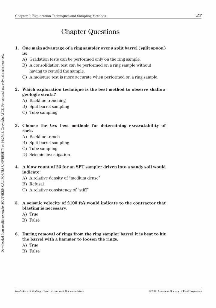
1. One main advantage of a ring sampler over a split barrel (split spoon) is:A) Gradation tests can be performed only on the ring sample.b) A consolidation test can be performed on a ring sample without
having to remold the sample.c) A moisture test is more accurate when performed on a ring sample.
2. Which exploration technique is the best method to observe shallow geologic strata?A) backhoe trenchingb) Split barrel samplingc) tube sampling
3. Choose the two best methods for determining excavatability of rock.A) backhoe trenchb) Split barrel samplingc) tube samplingD) Seismic investigation
4. A blow count of 23 for an SPT sampler driven into a sandy soil would indicate:A) A relative density of “medium dense”b) refusalc) A relative consistency of “stiff”
5. A seismic velocity of 2100 ft/s would indicate to the contractor that blasting is necessary.A) trueb) False
6. During removal of rings from the ring sampler barrel it is best to hit the barrel with a hammer to loosen the rings.A) trueb) False
Dow
nloa
ded
from
asc
elib
rary
.org
by
SOU
TH
ER
N C
AL
IFO
RN
IA U
NIV
ER
SIT
Y o
n 08
/27/
13. C
opyr
ight
ASC
E. F
or p
erso
nal u
se o
nly;
all
righ
ts r
eser
ved.

This page intentionally left blank
Dow
nloa
ded
from
asc
elib
rary
.org
by
SOU
TH
ER
N C
AL
IFO
RN
IA U
NIV
ER
SIT
Y o
n 08
/27/
13. C
opyr
ight
ASC
E. F
or p
erso
nal u
se o
nly;
all
righ
ts r
eser
ved.
Geotechnical Testing, Observation, and Documentation © 2008 American Society of civil Engineers 25
3Basic Laboratory Tests
During a geotechnical investigation or the grading of a construction site, many lab tests are performed to help determine the site soil conditions. Although there are many different types of lab tests, some are used more often than others. the tests presented in this chapter are some of the more commonly used.
the procedures described to perform each test are generally consistent with American Society for testing and materials (AStm) standards. However, it is recommended that current ASTM procedures be referred to during all testing, as these standards are recognized throughout the industry and updated on a regular basis. Along with each test described herein, a reference to the AStm test method is given in parentheses.
modified Proctor (AStm D1557)
the modified Proctor test determines the moisture content at which a given soil type will compact the best (i.e., achieve maximum density). this moisture–density relationship is determined by compacting a given volume of soil at a known moisture content into a standard-sized cylindrical mold. the maximum density test—AStm D1557—as described in this chapter, is referred to as the “modified Proctor.”
the original “Proctor test” was proposed by r. r. Proctor in 1933. AStm test method D698 (often referred to as the “standard Proctor”) was very similar to the method proposed by r. r. Proctor, with the exception that both AStm test methods (D1557 and D698) use a “free-fall drop” of the hammer, in lieu of “firm strokes” (which may give variable results). the modified Proctor test was introduced as an AStm Standard in 1958. During the 1970s and early 1980s the modified Proctor became more widely used as a modern replacement for the standard Proctor.
the primary differences between the modified Proctor and the standard Proctor are the hammer weights, the height of the drop, and the number of layers placed into the molds. the standard Proctor utilizes a 5.5-lb hammer with a 12-in. drop and three layers; the modified Proctor uses a 10-lb hammer, an 18-in. drop, and five layers. “the standard Proctor creates an effort of approximately 12,400 ft-lbf/ft3, whereas the modified Proctor creates a force of about 56,000 ft-lbf/ft3” (AStm volume 4.08). As compaction equipment became larger and heavier
Dow
nloa
ded
from
asc
elib
rary
.org
by
SOU
TH
ER
N C
AL
IFO
RN
IA U
NIV
ER
SIT
Y o
n 08
/27/
13. C
opyr
ight
ASC
E. F
or p
erso
nal u
se o
nly;
all
righ
ts r
eser
ved.
Geotechnical Testing, Observation, and Documentation © 2008 American Society of civil Engineers
26 chapter 3: basic laboratory tests
over the years (with larger vibratory compactors, heavier sheepsfoot rollers, etc., and with far heavier loads being transported over roads and highways) it became necessary to have a higher, more relevant compaction standard.
During the transition from the use of the standard Proctor to the modified Proc-tor there have been many misconceptions about the different need for each Proc-tor type. one common misunderstanding is that a 100% compaction obtained by the D698 “standard Proctor” is equivalent to a 95% compaction achieved by the D1557 method. Since the difference in load applied during each test is so great (12,400 versus 56,000 ft-lbf/ft3), a 95% compaction determined by using a modified Proctor is equivalent to more than a 103% compaction as obtained by a standard Proctor.
Another idea sometimes misstated is that one Proctor works better in some soils then the other method. the modified Proctor test is prepared in the lab in the same way as the standard Proctor (methods A, b, and c) for all soil types; how-ever, geotechnical engineers routinely adjust the moisture and density required (compaction) in the field when utilizing the modified Proctor dependent on the soil type or fill loading requirements (i.e., 95% for aggregate base, 87% to 92% at 2% to 4% over optimum for expansive clay, 90% for general engineered fill, or maybe even 100% compaction for an airport runway base course).
Synopsis
the test method described in this section is for a sample with no more than 20% of material retained on the #4 sieve, similar to AStm D1557 (test method A). the compaction of the sample is performed by dropping a 10-lb hammer a given number of times, then weighing the amount of soil compressed into the mold. (For method A, 25 drops are used; for a description of test methods b and c refer to AStm D1557.) this compaction procedure is repeated at various moisture contents (usually four)—from dry to wet.
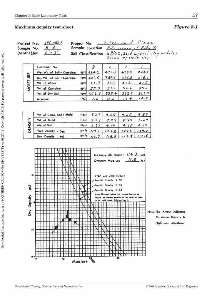
Each moisture content can be plotted against the corresponding dry density of the soil on graph paper (see Fig. 3-1), creating a “compaction curve.” the point at the top of the curve is where the “optimum moisture” and “maximum den-sity” meet. the moisture content at the maximum density is the water content at which the soil will generally compact best during the field grading process. When a field density test is taken, it is calculated against the laboratory maxi-mum density test, thus determining the percent compaction.
Apparatus
the equipment needed to perform the modified Proctor test consists of the following:
Mold: 4 in. in diameter by 4.58 in. in height (for a volume of 1⁄30 of a cubic foot).
Hammer: 10-lb with an 18-in. drop and with a 2-in. circular face; may be manually or mechanically operated.
Dow
nloa
ded
from
asc
elib
rary
.org
by
SOU
TH
ER
N C
AL
IFO
RN
IA U
NIV
ER
SIT
Y o
n 08
/27/
13. C
opyr
ight
ASC
E. F
or p
erso
nal u
se o
nly;
all
righ
ts r
eser
ved.
Geotechnical Testing, Observation, and Documentation © 2008 American Society of civil Engineers
chapter 3: basic laboratory tests 27
Maximum density test sheet. Figure 3-1
Dow
nloa
ded
from
asc
elib
rary
.org
by
SOU
TH
ER
N C
AL
IFO
RN
IA U
NIV
ER
SIT
Y o
n 08
/27/
13. C
opyr
ight
ASC
E. F
or p
erso
nal u
se o
nly;
all
righ
ts r
eser
ved.
Geotechnical Testing, Observation, and Documentation © 2008 American Society of civil Engineers
28 chapter 3: basic laboratory tests
Scales: a larger scale with a 20-kg minimum capacity (approximately 1 g accuracy) and a smaller 1-kg scale (approximately 0.1 g accuracy).
Sample extruder: a hydraulic car jack or other adapted equipment to help remove the soil from the sample mold.
Steel straight edge: approximately 12 in. long by 2 in. wide and having one beveled edge.
Sieve: #4 (4.75 mm).
Oven: thermostatically controlled to maintain a temperature of approxi-mately 230°F (110°c).
Additional equipment includes a graduated cylinder (in milliliters), mixing tools, mixing pans, and moisture sample containers. (containers should be numbered, preweighed, and labeled with indelible ink.)
Procedure
obtain a large (50-lb minimum) bulk sample from the field. Prior to testing, the sample must be visually classified (using the uScS), and the sample descrip-tion (including where the sample was obtained) must be written on the lab test sheet.
to start the test, pass the material through the #4 sieve, and set aside any plus #4 material, as it may be used for a specific gravity or other tests if required. (For this test it will be assumed that less than 5% of the material is retained on the #4 screen, so no “rock correction” will be calculated.) After the sample is passed through the sieve, its initial moisture content should be brought to a few percent under optimum by either adding moisture or by drying the soil. A good starting moisture is that at which when you squeeze the soil in your palm, it will just barely cling together.
For example, a predominantly sandy sample should barely clump together when squeezed in your hand, not leaving visible moisture in your palm when released, but a silty or clayey soil may cling together more readily when squeezed—but should not have enough moisture to be pressed into a pancake shape. blend and mix the moisture thoroughly into the sample to bring it to the starting point.
Tip: Excess moisture can be reduced by spreading the sample on a con-crete floor, by using a fan, or by drying the material in a low-temperature oven (<125°F).
next, divide the soil into four equal samples, each weighing about 2,500 g (approximately 5.5-lb each). label the samples 1 through 4. Sample #1 is already at the proper moisture content to begin the test and should now be sealed in an airtight container and labeled (Ø%). Each successive sample (or point) should have between 1.5% and 2% more moisture added to it than the preceding sample [2% of 2,500 = approximately 50 g (or ml) of water]. thoroughly mix the required
Dow
nloa
ded
from
asc
elib
rary
.org
by
SOU
TH
ER
N C
AL
IFO
RN
IA U
NIV
ER
SIT
Y o
n 08
/27/
13. C
opyr
ight
ASC
E. F
or p
erso
nal u
se o
nly;
all
righ
ts r
eser
ved.
Geotechnical Testing, Observation, and Documentation © 2008 American Society of civil Engineers
chapter 3: basic laboratory tests 29
water into each sample. Seal each sample in an airtight container and label it accordingly (+ 2%, + 4%, etc.). leave the samples sealed to cure—so that the moisture is distributed evenly throughout—2 to 4 hours for nonplastic soils, and up to 16 hours for very clayey material. this cure time is essential for mois-ture consistency. Incomplete curing is often the cause of inaccurate points on the curve.
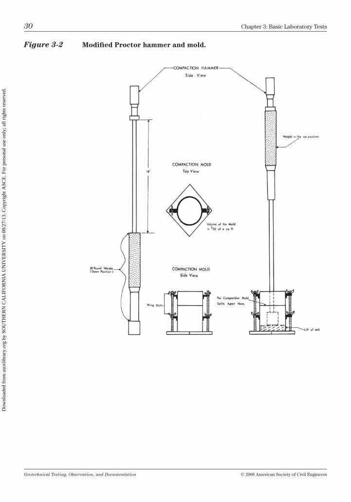
After curing, the samples are ready for compacting. Place the compaction mold on a level concrete surface. Put one layer (lift) of soil (1⁄5 of the sample, about 500 g) from sample container #1 into the mold. compact this first layer of soil with 25 blows from the compaction hammer, distributing the blows evenly over the sample surface. the hammer should be raised the full 18 in., then allowed to drop—in free fall—to strike the soil.
Tip: the inside of the mold may be sprayed with a light layer of lubri-cant (such as WD-40tm) to help ease the removal of the specimen from the mold.
in a similar manner, compact the remaining four equal lifts of soil from sample container #1, with the fifth and final compacted layer filling slightly higher than the horizontal split—where the top of the mold separates (see Fig. 3-2).
Tip: After compacting each lift, some soil may adhere to the face of the compaction hammer; carefully lay the hammer down and scrape off the excess material prior to compacting the next lift. if the excess soil is allowed to remain on the hammer face, the drop may be softened, thus skewing the results.
Separate and remove the top and bottom portions from the mold. using a straight edge trim off all excess material so that the soil is level with the top of the mold. Any small holes or voids should be filled with the trimmed material and then patted flush into place. Weigh the mold and the soil, and then record the weight as shown in Fig. 3-1. next, extrude the soil from the mold. take a representative portion (approximately 500 g) of material axially from the central portion of the sample. Place this material in a numbered container and weigh it on the smaller scale, and then enter the weight and container number on the test sheet. Place the container in the oven to dry. When dried, this sample will be weighed for the moisture calculation.
repeat the same procedures for samples #2 through #4, being sure to obtain a moisture sample for each “point” pounded. An attempt should be made to compact two points on the dry side of the optimum moisture content and two points on the wet side. Four points separated in this manner will help to create a well-formed compaction curve. After the moisture samples are dried, weigh them; record each weight on the test sheet.
Tip: During the compaction of predominantly sandy, gravelly, and non-plastic silty soils into the mold, water will begin to seep from the bottom of the mold at the point when the soil is barely over-optimum, whereas
Dow
nloa
ded
from
asc
elib
rary
.org
by
SOU
TH
ER
N C
AL
IFO
RN
IA U
NIV
ER
SIT
Y o
n 08
/27/
13. C
opyr
ight
ASC
E. F
or p
erso
nal u
se o
nly;
all
righ
ts r
eser
ved.
Geotechnical Testing, Observation, and Documentation © 2008 American Society of civil Engineers
30 chapter 3: basic laboratory tests
Figure 3-2 Modified Proctor hammer and mold.
Dow
nloa
ded
from
asc
elib
rary
.org
by
SOU
TH
ER
N C
AL
IFO
RN
IA U
NIV
ER
SIT
Y o
n 08
/27/
13. C
opyr
ight
ASC
E. F
or p
erso
nal u
se o
nly;
all
righ
ts r
eser
ved.
Geotechnical Testing, Observation, and Documentation © 2008 American Society of civil Engineers
chapter 3: basic laboratory tests 31
clays and low plastic silts will begin to appear mushy or spongy in the mold as they go over-optimum.
Calculations
the calculations needed for the modified Proctor are as follows (see Fig. 3-1):
1. First calculate the percent moisture:
percent moisture = (W/D ) × 100,
where
W, weight of water = (wet weight of soil and container) – (dry weight of soil and container)
and
D, weight of dry soil = (dry weight of soil and container) – (weight of container).
2. Determine the wet density:
wet density = [(weight of soil in grams) / (453.6)] × (30),
where
weight of soil = (weight of compacted soil and mold) – (weight of mold).
3. Determine the dry density:
dry density = (wet density) / (100 + percent moisture) × 100.
4. Plot each point (dry density versus moisture) on the test sheet graph, then draw a curve through them. the maximum density and optimum moisture con-tents meet at the top of the curve.
Sieve Analysis (AStm D422)
the sieve analysis is used to determine the grain-size distribution of material with particle diameters larger than the #200 sieve. When a hydrometer analysis is performed on the same sample, a full grain-size distribution curve may be drawn, indicating the minus #200 material as well.
Dow
nloa
ded
from
asc
elib
rary
.org
by
SOU
TH
ER
N C
AL
IFO
RN
IA U
NIV
ER
SIT
Y o
n 08
/27/
13. C
opyr
ight
ASC
E. F
or p
erso
nal u
se o
nly;
all
righ
ts r
eser
ved.
Geotechnical Testing, Observation, and Documentation © 2008 American Society of civil Engineers
32 chapter 3: basic laboratory tests
Apparatus
For the sieve analysis the following equipment is needed:
Set of sieves: as pictured in Fig. 3-3 or any other desired combination.
Scales: accurate to 0.1 g for >#10 material and 0.01 g for weighing <#10 material.
Sieve shaker: preferably with a timer.
Oven: set at 230°F (110°c).
#200 wash sieve: a sieve with high sides (75 µm).
Sink: with a small hose to rinse soil through the wash sieve.
Soaking solution: sodium hexametaphosphate solution (40 g per l of dis-tilled water).
Soaking container: metal pan, porcelain bowl, or a similar container that has been numbered, preweighed, and labeled with indelible ink.
Procedure
Place a representative portion of the soil sample in the oven until it is thoroughly dried. For material 3⁄8 in. and smaller a minimum sample of 500 g will suffice. (refer to AStm D1140 for additional minimum weight requirements.) Weigh the initial sample. Enter this weight as the total sample weight. Pour the sample into the soaking pan. Fill the pan with enough soaking solution to completely cover the sample. low cohesive soils should be allowed to soak a minimum of 2 hours (and moderate to highly plastic soils should soak overnight) to soften and break down the adhesion of clay and silt particles.
After the soaking is complete, wash the sample over a #200 wash sieve. con-tinue to wash the sample until no more fines (silt or clay) appear to be passing through the sieve. then, carefully position the sieve over the soaking pan and rinse the remaining soil back into it. Pour off the excess water, taking care not to pour out any of the remaining soil. Place the sample into the oven to dry.
Arrange a set of sieves in order of opening size—from large to small, top to bottom (Fig. 3-3). remove the dry soil from the oven and pour the soil into the top sieve, using a brush as necessary to dislodge all adhering soil from the sample pan. cover the stacked sieves and tighten them onto the shaker. let the sieves shake for at least 15 minutes, or until all the grains of soil have passed through all the sieves possible.
Dow
nloa
ded
from
asc
elib
rary
.org
by
SOU
TH
ER
N C
AL
IFO
RN
IA U
NIV
ER
SIT
Y o
n 08
/27/
13. C
opyr
ight
ASC
E. F
or p
erso
nal u
se o
nly;
all
righ
ts r
eser
ved.
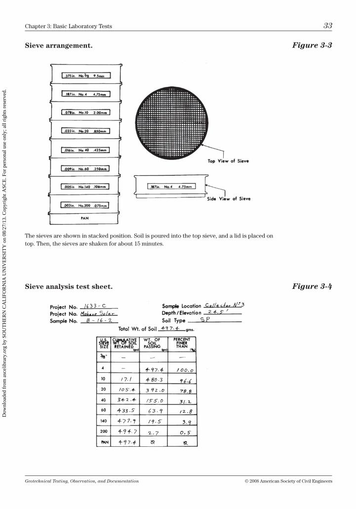
Geotechnical Testing, Observation, and Documentation © 2008 American Society of civil Engineers
chapter 3: basic laboratory tests 33
Sieve arrangement. Figure 3-3
Sieve analysis test sheet. Figure 3-4
the sieves are shown in stacked position. Soil is poured into the top sieve, and a lid is placed on top. then, the sieves are shaken for about 15 minutes.
Dow
nloa
ded
from
asc
elib
rary
.org
by
SOU
TH
ER
N C
AL
IFO
RN
IA U
NIV
ER
SIT
Y o
n 08
/27/
13. C
opyr
ight
ASC
E. F
or p
erso
nal u
se o
nly;
all
righ
ts r
eser
ved.
Geotechnical Testing, Observation, and Documentation © 2008 American Society of civil Engineers
34 chapter 3: basic laboratory tests
After shaking, weigh the soil from each sieve, starting with the largest screen, adding each weight together (weighing in a cumulative manner). record each weight on the test sheet, as shown in Fig. 3-4.
Tip: to help remove material from the larger screens, use a small stiff wire brush. A softer brush should be used on the smaller size (nylon) sieves.
Calculations
to complete the sieve analysis, perform the following calculations (see Fig. 3-4):
1. First determine the cumulative weight of soil retained:
cumulative weight of soil retained = (weight of soil retained from each individual sieve) + (cumulative weight retained on all larger sieves).
2. the weight of soil passing through the sieve is then calculated by:
weight of soil passing = (total weight of soil) – (cumulative weight).
3. the percentages are found by:
percent finer than = [(weight of soil passing) / (total weight of soil)] × (100).
hydrometer Analysis (AStm D422)
the hydrometer analysis uses a sedimentation process to determine the parti-cle-size distribution of material finer than the #200 sieve. A grain-size distribu-tion curve may be drawn from the resulting figures and may be combined with the grain-size curve obtained from the plus #200 material.
Apparatus
hydrometer analysis requires the following equipment:
1,000-ml sedimentation cylinders: approximately 18 in. tall by 2.5 in. in diameter.
Hydrometer: 52h.
Sieves: #10 (2 mm) and #200 wash sieve (75 µm).
Bowl with pestle: hard rubber-tipped pestle preferred.
Scales: accurate to 0.1 g (for material retained on the #10 sieve) and 0.01 g (for material passing the #10 sieve).
Squirt bottle: used to rinse material from the inside of cups and cylinders.
Dow
nloa
ded
from
asc
elib
rary
.org
by
SOU
TH
ER
N C
AL
IFO
RN
IA U
NIV
ER
SIT
Y o
n 08
/27/
13. C
opyr
ight
ASC
E. F
or p
erso
nal u
se o
nly;
all
righ
ts r
eser
ved.
Geotechnical Testing, Observation, and Documentation © 2008 American Society of civil Engineers
chapter 3: basic laboratory tests 35
Thermometer: accurate to 1°c.
Dispersing solution: sodium hexametaphosphate solution (40 g per l of dis-tilled water).
Dispersing containers: small porcelain bowls or similar containers.
Weighing containers: tared and numbered with indelible ink.
Mixing apparatus: for example, a milkshake mixer with a mixing cup.
Timing device: watch, clock, timer, etc.
note that all water used should be distilled and the room in which the analysis is done should have a fairly constant temperature.
Procedure
Air dry a representative sample. break up the sample with a pestle in a bowl. next, pass the sample through the #10 sieve, allowing for enough sample to be weighed out as follows: if the sample is predominantly clayey or silty, use ≥50 g of soil; if the sample is primarily sandy, use ≥100 g of material.
Place the sample in a dispersing bowl, add 125 ml of dispersing solution, and stir well. let the mixture soak for at least 16 hours. After the soaking period, using a squirt bottle of distilled water, transfer the mixture into the mixing cup. Fill the mixing cup about half full with more distilled water. mix for one minute. next transfer the mixture into a 1,000-ml sedimentation cylinder; again, a squirt bottle may be used to aid the transfer. Fill the cylinder to the 1,000-ml level with distilled water.
using a rubber stopper (or the palm of your hand) to cover the top of the cylin-der, turn the cylinder upside down and back for a period of one minute, invert-ing the cylinder approximately one turn per second. When finished, place the cylinder on a level surface and remove the stopper from the top. immediately observe the time and record it on the test sheet (see Fig. 3-5). After completion of shaking, the hydrometer readings should be read and recorded as the actual reading at the following intervals: 2, 5, 15, 30, 60, 250, and 1,440 minutes. At each time interval, a control reading should be recorded from the control sedi-mentation cylinder. temperature readings are also recorded from the control sedimentation cylinder at each interval.
hydrometer readings must be read at the top of the meniscus (the top of the water surface formed around the hydrometer stem). between readings, the hydrometer should be placed in the control cylinder, not left in a test cylinder. refer to Fig. 3-6 for a typical test arrangement.
After the final reading has been taken, transfer the material out of the cylinder onto a #200 sieve and continue to wash it until no more material is observed to pass through the sieve. transfer the material retained on the sieve (using a
Dow
nloa
ded
from
asc
elib
rary
.org
by
SOU
TH
ER
N C
AL
IFO
RN
IA U
NIV
ER
SIT
Y o
n 08
/27/
13. C
opyr
ight
ASC
E. F
or p
erso
nal u
se o
nly;
all
righ
ts r
eser
ved.
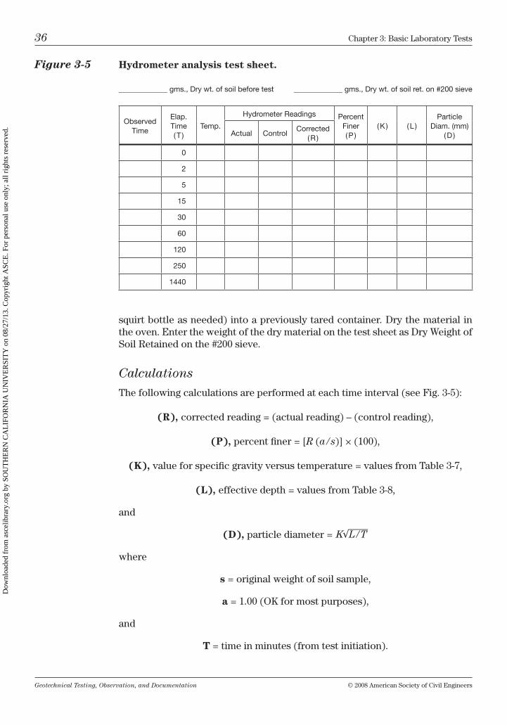
Geotechnical Testing, Observation, and Documentation © 2008 American Society of civil Engineers
36 chapter 3: basic laboratory tests
squirt bottle as needed) into a previously tared container. Dry the material in the oven. Enter the weight of the dry material on the test sheet as Dry Weight of Soil retained on the #200 sieve.
Calculations
the following calculations are performed at each time interval (see Fig. 3-5):
(R), corrected reading = (actual reading) – (control reading),
(P), percent finer = [R (a / s)] × (100),
(K), value for specific gravity versus temperature = values from table 3-7,
(L), effective depth = values from table 3-8,
and
(D), particle diameter =
where
s = original weight of soil sample,
a = 1.00 (ok for most purposes),
and
T = time in minutes (from test initiation).
Figure 3-5 Hydrometer analysis test sheet.
_____________ gms., Dry wt. of soil before test _____________ gms., Dry wt. of soil ret. on #200 sieve
Observed Time
Elap. Time ( T )
Temp.
Hydrometer Readings Percent Finer ( P )
( K ) ( L )Particle
Diam. (mm) ( D )Actual Control
Corrected ( R )
0
2
5
15
30
60
120
250
1440
Dow
nloa
ded
from
asc
elib
rary
.org
by
SOU
TH
ER
N C
AL
IFO
RN
IA U
NIV
ER
SIT
Y o
n 08
/27/
13. C
opyr
ight
ASC
E. F
or p
erso
nal u
se o
nly;
all
righ
ts r
eser
ved.
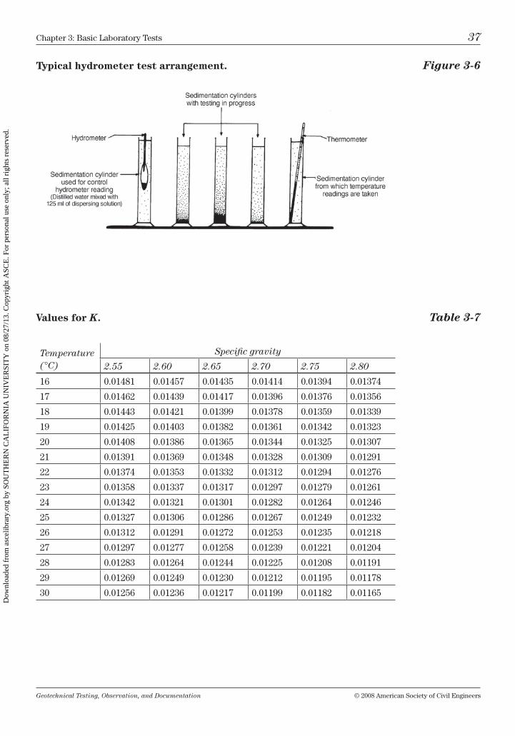
Geotechnical Testing, Observation, and Documentation © 2008 American Society of civil Engineers
chapter 3: basic laboratory tests 37
Typical hydrometer test arrangement. Figure 3-6
Values for K. Table 3-7
Temperature (°C)
Specific gravity
2.55 2.60 2.65 2.70 2.75 2.80
16 0.01481 0.01457 0.01435 0.01414 0.01394 0.01374
17 0.01462 0.01439 0.01417 0.01396 0.01376 0.01356
18 0.01443 0.01421 0.01399 0.01378 0.01359 0.01339
19 0.01425 0.01403 0.01382 0.01361 0.01342 0.01323
20 0.01408 0.01386 0.01365 0.01344 0.01325 0.01307
21 0.01391 0.01369 0.01348 0.01328 0.01309 0.01291
22 0.01374 0.01353 0.01332 0.01312 0.01294 0.01276
23 0.01358 0.01337 0.01317 0.01297 0.01279 0.01261
24 0.01342 0.01321 0.01301 0.01282 0.01264 0.01246
25 0.01327 0.01306 0.01286 0.01267 0.01249 0.01232
26 0.01312 0.01291 0.01272 0.01253 0.01235 0.01218
27 0.01297 0.01277 0.01258 0.01239 0.01221 0.01204
28 0.01283 0.01264 0.01244 0.01225 0.01208 0.01191
29 0.01269 0.01249 0.01230 0.01212 0.01195 0.01178
30 0.01256 0.01236 0.01217 0.01199 0.01182 0.01165
Dow
nloa
ded
from
asc
elib
rary
.org
by
SOU
TH
ER
N C
AL
IFO
RN
IA U
NIV
ER
SIT
Y o
n 08
/27/
13. C
opyr
ight
ASC
E. F
or p
erso
nal u
se o
nly;
all
righ
ts r
eser
ved.
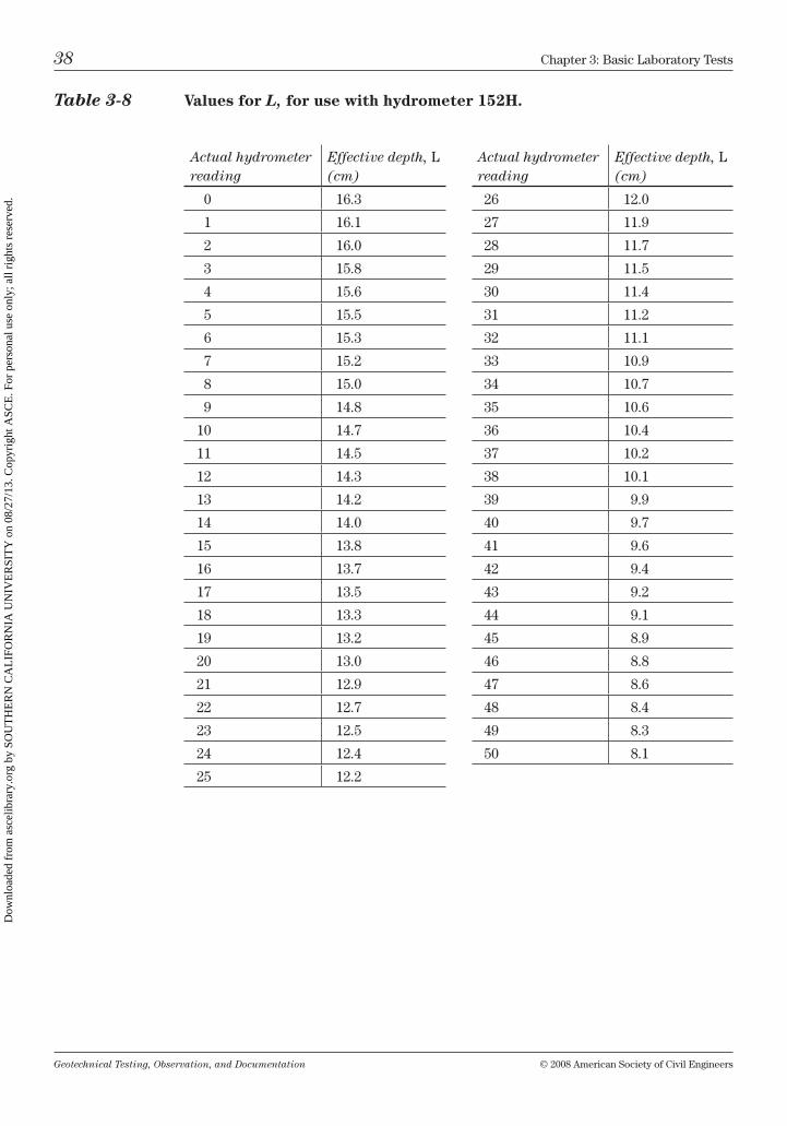
Geotechnical Testing, Observation, and Documentation © 2008 American Society of civil Engineers
38 chapter 3: basic laboratory tests
Actual hydrometer reading
Effective depth, l (cm)
0 16.3
1 16.1
2 16.0
3 15.8
4 15.6
5 15.5
6 15.3
7 15.2
8 15.0
9 14.8
10 14.7
11 14.5
12 14.3
13 14.2
14 14.0
15 13.8
16 13.7
17 13.5
18 13.3
19 13.2
20 13.0
21 12.9
22 12.7
23 12.5
24 12.4
25 12.2
Actual hydrometer reading
Effective depth, l (cm)
26 12.0
27 11.9
28 11.7
29 11.5
30 11.4
31 11.2
32 11.1
33 10.9
34 10.7
35 10.6
36 10.4
37 10.2
38 10.1
39 9.9
40 9.7
41 9.6
42 9.4
43 9.2
44 9.1
45 8.9
46 8.8
47 8.6
48 8.4
49 8.3
50 8.1
Table 3-8 Values for L, for use with hydrometer 152H.
Dow
nloa
ded
from
asc
elib
rary
.org
by
SOU
TH
ER
N C
AL
IFO
RN
IA U
NIV
ER
SIT
Y o
n 08
/27/
13. C
opyr
ight
ASC
E. F
or p
erso
nal u
se o
nly;
all
righ
ts r
eser
ved.
Geotechnical Testing, Observation, and Documentation © 2008 American Society of civil Engineers
chapter 3: basic laboratory tests 39
Plastic and liquid limits test (AStm D4318)
this test (sometimes referred to as the Atterberg limits) is used to determine the plasticity index (Pi) of silty and clayey soils. commonly a Pi of 15 or greater (as in Appendix J of the international building code) is used to distinguish a point between low and moderately expansive soil.
the plastic and liquid limits are defined as follows:
Plastic limit: (1) the water content at which a soil will just begin to crumble when rolled into a thread approximately 1⁄8 in. in diameter. (2) the water con-tent corresponding to an arbitrary limit between the plastic and semisolid consistency states of a soil.
Liquid limit: (1) the water content at which a pat of soil, cut by a groove of standard dimensions, will flow together for a distance of ½ in. under the impact of 25 drops by a standard liquid limits device. (2) the water content corresponding to an arbitrary limit between the liquid and plastic consis-tency states of a soil.
Apparatus
For a plastic and liquid limits test, you will need the following:
Mixing bowl: porcelain bowl 4 to 5 in. in diameter.
Rubber-tipped pestle and mortar (bowl).
Spatula: having a flexible blade approximately 3 in. long by ½ in. to ¾ in. wide.
Liquid limits device: a mechanical device consisting of a brass cup with a hard rubber base, as shown in Fig. 3-9.
Grooving tool: a combination grooving tool and height calibration gauge, as depicted in Fig. 3-9, or refer to AStm for an alternative flat style; many laboratory technicians feel that the rounded grooving tool—as shown in this text—is easier to use and may “tear” the soil less than the flat grooving tool.
Drying containers: small containers about 1 ½ in. in diameter, tared and numbered with indelible ink.
Scale: accurate to 0.01 g.
Ground glass plate: at least 12 in. square by 3⁄8 in. thick.
Sieve: #40 (425 µm).
Dow
nloa
ded
from
asc
elib
rary
.org
by
SOU
TH
ER
N C
AL
IFO
RN
IA U
NIV
ER
SIT
Y o
n 08
/27/
13. C
opyr
ight
ASC
E. F
or p
erso
nal u
se o
nly;
all
righ
ts r
eser
ved.
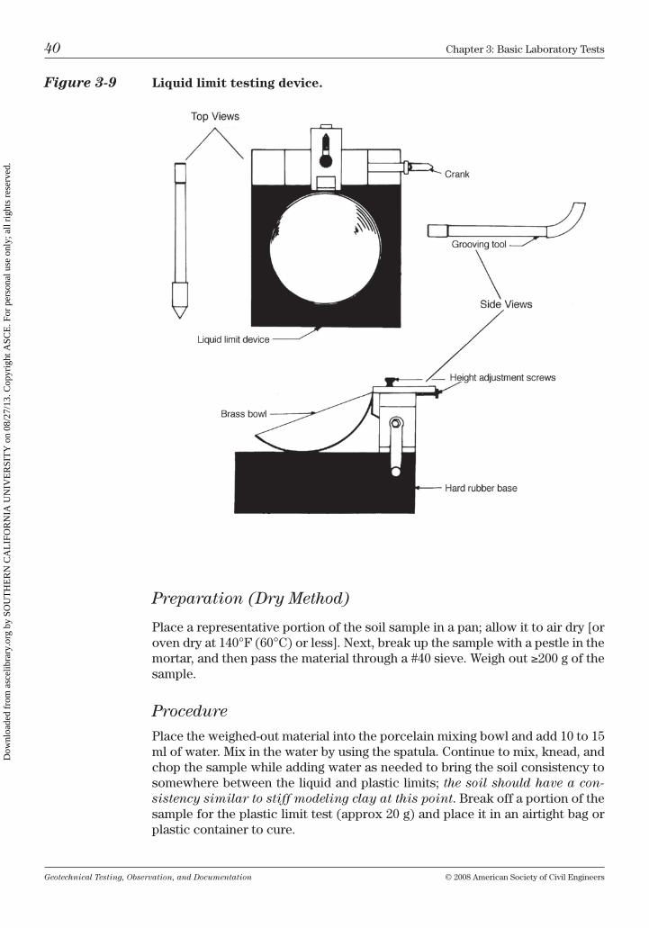
Geotechnical Testing, Observation, and Documentation © 2008 American Society of civil Engineers
40 chapter 3: basic laboratory tests
Preparation (Dry Method)
Place a representative portion of the soil sample in a pan; allow it to air dry [or oven dry at 140°F (60°c) or less]. next, break up the sample with a pestle in the mortar, and then pass the material through a #40 sieve. Weigh out ≥200 g of the sample.
Procedure
Place the weighed-out material into the porcelain mixing bowl and add 10 to 15 ml of water. mix in the water by using the spatula. continue to mix, knead, and chop the sample while adding water as needed to bring the soil consistency to somewhere between the liquid and plastic limits; the soil should have a con-sistency similar to stiff modeling clay at this point. break off a portion of the sample for the plastic limit test (approx 20 g) and place it in an airtight bag or plastic container to cure.
Figure 3-9 Liquid limit testing device.
Dow
nloa
ded
from
asc
elib
rary
.org
by
SOU
TH
ER
N C
AL
IFO
RN
IA U
NIV
ER
SIT
Y o
n 08
/27/
13. C
opyr
ight
ASC
E. F
or p
erso
nal u
se o
nly;
all
righ
ts r
eser
ved.
Geotechnical Testing, Observation, and Documentation © 2008 American Society of civil Engineers
chapter 3: basic laboratory tests 41
Seal the remaining portion of the sample (approx 175 g) in another airtight container. this portion will be used for the liquid limit test. let both of these samples cure for a minimum of 16 hours. this will ensure that the water and soil particles are thoroughly blended together.
Plastic Limit
remove half of the soil to be used for the plastic limit test from the container. Squeeze and mold the sample into an oblong mass, then place the soil mass on the glass plate. use your fingers to roll the soil mass into a thread with a diam-eter of 1⁄8 in. Pick up the thread and remold it into an oblong mass. Again, roll it into a thread 1⁄8 in. in diameter. repeat this operation until the soil can no longer be rolled into any 1⁄8-in.-diameter threads but crumbles and cracks apart at, or just before reaching, 1⁄8 in. in diameter. immediately place the crumbled soil into a container and record the weight (as shown in Fig. 3-10). Place the sample in the oven to dry at 230°F (110°c). repeat this procedure for the remaining half of the sample. Again, place the crumbled soil into a container, weigh it, and place it in the oven to dry.
Tip: if the sample is very wet, rolling it on paper (with nonremovable fibers) will help to absorb moisture.
the point at which the soil breaks apart and can no longer be rolled into a 1⁄8-in. thread is the plastic limit. Any sample that cannot be rolled into a 1⁄8-in. thread (no matter how the moisture is adjusted) should be considered nonplastic.
Liquid Limit
Step 1
remove from the container the soil to be used for the liquid limit test. Add 3 to 5 ml of water and thoroughly mix by chopping, mixing, and kneading.
Step 2
Place a portion of the soil in the liquid limits device brass bowl (shown in Fig. 3-9). using a spatula, level the soil pat (without trapping any air bubbles in the mass) to a thickness of one centimeter, as shown in Fig. 3-11. using the grooving tool, cut a groove through the center of the soil pat (again refer to Fig. 3-11).
Tip: When using the grooving tool, try to avoid tearing the sample; it is helpful to use a rolling motion while cutting the groove.
Step 3
turn the crank on the liquid limits device at a steady speed (approximately two drops per second) until the soil mass has flown together to create a ½-in. closure. if a closure of ½ in. is achieved at between 30 and 35 drops, proceed to step 4.
Dow
nloa
ded
from
asc
elib
rary
.org
by
SOU
TH
ER
N C
AL
IFO
RN
IA U
NIV
ER
SIT
Y o
n 08
/27/
13. C
opyr
ight
ASC
E. F
or p
erso
nal u
se o
nly;
all
righ
ts r
eser
ved.
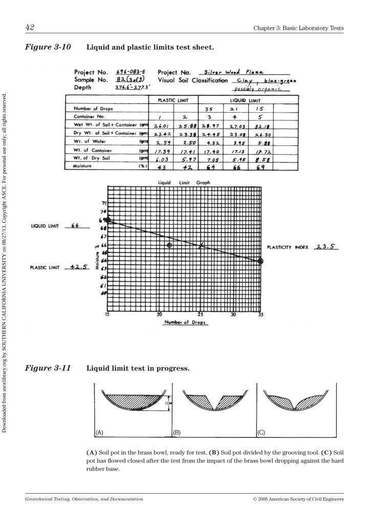
Geotechnical Testing, Observation, and Documentation © 2008 American Society of civil Engineers
42 chapter 3: basic laboratory tests
Figure 3-10 Liquid and plastic limits test sheet.
Figure 3-11 Liquid limit test in progress.
(A) Soil pot in the brass bowl, ready for test. (B) Soil pot divided by the grooving tool. (C) Soil pot has flowed closed after the test from the impact of the brass bowl dropping against the hard rubber base.
Dow
nloa
ded
from
asc
elib
rary
.org
by
SOU
TH
ER
N C
AL
IFO
RN
IA U
NIV
ER
SIT
Y o
n 08
/27/
13. C
opyr
ight
ASC
E. F
or p
erso
nal u
se o
nly;
all
righ
ts r
eser
ved.
Geotechnical Testing, Observation, and Documentation © 2008 American Society of civil Engineers
chapter 3: basic laboratory tests 43
if more than 35 drops are necessary to obtain the ½-in. closure, add more mois-ture and remix, as described in step 1. if the sample requires fewer than 30 blows for proper closure, then the sample is too wet. in that case continue to mix the sample until it has sufficiently dried back. Do not add more soil to help dry the sample back; adding dry soil will create an inconsistently mixed sample (from lack of curing), thus putting the accuracy of the test in question.
repeat steps 1 through 3 until the proper closure is achieved at between 30 and 35 blows, then proceed to step 4.
Step 4
using the spatula, immediately remove a portion of the soil pat (approximately 10 to 15 g) from the ½-in. closure. Place the sample in a numbered container. record the weight and the number of drops on the test sheet, and then place the sample in the oven to dry at 230°F (110°c).
repeat steps 1 through 4 as needed to obtain two more samples: one sample closing between 20 and 30 drops and one sample obtained from between 15 and 20 drops. this will allow three liquid limit samples to be plotted as points on a graph.
Step 5
Weigh all of the plastic and liquid limit samples that have been dried in the oven.
Calculations
Perform the following calculations (see Fig. 3-10):
1. First calculate the percent moisture:
percent moisture = (W/D) 100,
where
(W), weight of water = (wet weight of soil and container) – (dry weight of soil and container)
and
(D), weight of dry soil = (dry weight of soil and container) – (weight of container).
2. then determine the plastic limit:
plastic limit (PL) = [(percent moisture of plastic limit sample #1) + (percent moisture of plastic limit sample #2)] / 2.
Dow
nloa
ded
from
asc
elib
rary
.org
by
SOU
TH
ER
N C
AL
IFO
RN
IA U
NIV
ER
SIT
Y o
n 08
/27/
13. C
opyr
ight
ASC
E. F
or p
erso
nal u
se o
nly;
all
righ
ts r
eser
ved.
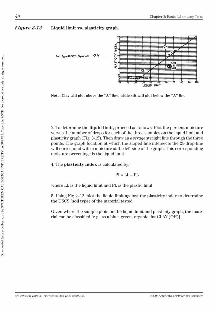
Geotechnical Testing, Observation, and Documentation © 2008 American Society of civil Engineers
44 chapter 3: basic laboratory tests
3. to determine the liquid limit, proceed as follows: Plot the percent moisture versus the number of drops for each of the three samples on the liquid limit and plasticity graph (Fig. 3-12). then draw an average straight line through the three points. the graph location at which the sloped line intersects the 25-drop line will correspond with a moisture at the left side of the graph. this corresponding moisture percentage is the liquid limit.
4. the plasticity index is calculated by:
Pi = ll – Pl
where ll is the liquid limit and Pl is the plastic limit.
5. using Fig. 3-12, plot the liquid limit against the plasticity index to determine the uScS (soil type) of the material tested.
Given where the sample plots on the liquid limit and plasticity graph, the mate-rial can be classified [e.g., as a blue–green, organic, fat clAy (oh)].
Figure 3-12 Liquid limit vs. plasticity graph.
Note: Clay will plot above the “A” line, while silt will plot below the “A” line.
Dow
nloa
ded
from
asc
elib
rary
.org
by
SOU
TH
ER
N C
AL
IFO
RN
IA U
NIV
ER
SIT
Y o
n 08
/27/
13. C
opyr
ight
ASC
E. F
or p
erso
nal u
se o
nly;
all
righ
ts r
eser
ved.
Geotechnical Testing, Observation, and Documentation © 2008 American Society of civil Engineers
chapter 3: basic laboratory tests 45
chapter Questions
1. Which type of Proctor uses a 10-lb hammer and an 18-in. drop?A) the original Proctor proposed by r. r. Proctorb) the modified Proctor (AStm D1557)c) the standard Proctor (AStm D698)
2. In ASTM D1557 method A, what size screen is the material sieved through?A) #200b) #40c) #4
3. Optimum moisture is the point that:A) A sandy soil should be screened across the #4 sieveb) A fine-grained soil becomes liquidc) Soil will compact best in both the field and laboratoryD) no more water can be retained in a soil
4. A 40% solution of sodium hexametaphosphate is used to:A) remove dry soil from dirty sievesb) break down adhesion of noncohesive soilsc) Soften and break down the adhesion of cohesive soilsD) none of the above
5. The hydrometer analysis is used to determine the particle-size dis-tribution of:A) Sand, clay, and siltb) Sand and colloidsc) material finer than the #20 sieveD) none of the above
6. Hydrometer readings should always be taken at the top of the meniscus.A) trueb) False
Dow
nloa
ded
from
asc
elib
rary
.org
by
SOU
TH
ER
N C
AL
IFO
RN
IA U
NIV
ER
SIT
Y o
n 08
/27/
13. C
opyr
ight
ASC
E. F
or p
erso
nal u
se o
nly;
all
righ
ts r
eser
ved.
Geotechnical Testing, Observation, and Documentation © 2008 American Society of civil Engineers
46 chapter 3: basic laboratory tests
7. A sample that cannot be rolled smaller than 1⁄8 in. without crumbling is to be considered:A) cl/ml (per the liquid limit and plasticity graph)b) medium plasticc) nonplasticD) to have a high liquid limit
8. PI = LL – PL.A) trueb) False
Dow
nloa
ded
from
asc
elib
rary
.org
by
SOU
TH
ER
N C
AL
IFO
RN
IA U
NIV
ER
SIT
Y o
n 08
/27/
13. C
opyr
ight
ASC
E. F
or p
erso
nal u
se o
nly;
all
righ
ts r
eser
ved.
Geotechnical Testing, Observation, and Documentation © 2008 American Society of civil Engineers 47
Field Density Tests
Field density tests are used to measure the amount of moisture and the percent compaction of the material placed during backfill or grading operations. both the sand cone and nuclear gauge tests measure the moisture content and degree of compaction, which are usually expressed as a percentage. the percent mois-ture indicates the average amount of water at a specific location. the percent compaction is typically defined by the in-place dry density of a soil at a certain location compared with the laboratory maximum dry density of that same soil type (as determined by the modified Proctor test described in chapter 3).
one of the most important steps when taking a field density test is choosing the correct Proctor sample from a list of site compaction curves. choose the Proctor carefully by matching the soil type at the density test location with the description of one of the Proctors.
Remember: When choosing a Proctor, always choose the correct Proc-tor by matching the soil type in the field with the soil description of the Proctor; never choose a Proctor just because the maximum density “looks right” or will make the test pass.
Density tests are taken wherever fill is placed for structural support or road base to help confirm that the soil is being adequately moisture conditioned and densified per the project recommendations. Poorly compacted material below footing or slab areas can lead to settlement, which may be observed as wall and ceiling cracks, differential settlement of floors, and windows or doors not open-ing or sliding properly. improper moisture conditioning of expansive soils (typi-cally clays) can result in cracked, separated, or tilted floor slabs and footings.
Density testing of trench backfill is also required. often the technician is not on site full-time during the placement of trench backfill. therefore, density tests must be taken at a number of different locations and depths within the trench to help confirm that the trench soils have been sufficiently compacted. improper compaction of trench backfill can cause settlement in streets (“potholes”), lead to cracked sidewalks, and even break utility lines.
this chapter describes two of the most commonly used field density test methods—the sand cone test and the nuclear gauge test. the procedures described in this chapter to perform the sand cone and nuclear gauge density tests are generally consistent with AStm test methods D1556 and AStm D6938,
4
Dow
nloa
ded
from
asc
elib
rary
.org
by
SOU
TH
ER
N C
AL
IFO
RN
IA U
NIV
ER
SIT
Y o
n 08
/27/
13. C
opyr
ight
ASC
E. F
or p
erso
nal u
se o
nly;
all
righ
ts r
eser
ved.
Geotechnical Testing, Observation, and Documentation © 2008 American Society of civil Engineers
48 chapter 4: Field Density tests
respectively. however, it is recommended that current ASTM procedures be observed, as these standards are recognized throughout the industry and updated periodically.
Sand cone test (AStm D1556)
the sand cone (see Fig. 4-1) has been widely used for many years to determine in-place field density. Although the sand cone has proven very reliable in most soil conditions, the nuclear gauge density test is becoming the test of choice. owing in part to the slower test results of the sand cone as well as the bulki-ness of the equipment (sand, scales, buckets, etc.), most testing agencies are now using the nuclear gauge in lieu of the sand cone. nevertheless, the sand cone test is still used by many geotechnical firms, sometimes as the preferred method for forensic studies (legal investigations to determine why a structure may have failed), as a referee method, or simply because the equipment is less expensive than a nuclear gauge. (See also Fig. 4-2.)
Overview
by digging a hole, weighing the removed soil, and then pouring a measured amount of sand from the sand cone into the hole, the dry density of the soil can be calculated. this dry density is then divided into the maximum density of the soil (from the laboratory Proctor) to determine the percent compaction of the fill placed.
Apparatus
Performance of a sand cone test requires the following supplies:
Sand cone: aluminum funnel and glass or plastic jar (with plastic being preferred).
Aluminum base plate.
Bucket or container: to hold the soil removed from the hole (and help carry tools in).
Scales: 1-kg scale accurate to 0.1 g and 20-kg scale accurate to approximately 1 g.
Camp stove or oven: for moisture burn-out.
Pan or container: for moisture sample.
Digging tools: scoop or large spoon, screwdriver or chisel, paint brush (and any other tools helpful in digging a test hole).
#20 or #30 silica sand: for which the unit weight is precalibrated (or refer to AStm 1556.A2).
Dow
nloa
ded
from
asc
elib
rary
.org
by
SOU
TH
ER
N C
AL
IFO
RN
IA U
NIV
ER
SIT
Y o
n 08
/27/
13. C
opyr
ight
ASC
E. F
or p
erso
nal u
se o
nly;
all
righ
ts r
eser
ved.
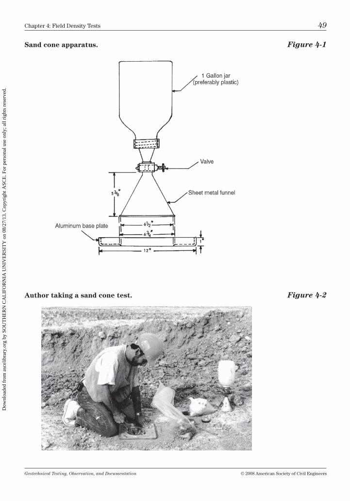
Geotechnical Testing, Observation, and Documentation © 2008 American Society of civil Engineers
chapter 4: Field Density tests 49
Sand cone apparatus. Figure 4-1
Author taking a sand cone test. Figure 4-2
Dow
nloa
ded
from
asc
elib
rary
.org
by
SOU
TH
ER
N C
AL
IFO
RN
IA U
NIV
ER
SIT
Y o
n 08
/27/
13. C
opyr
ight
ASC
E. F
or p
erso
nal u
se o
nly;
all
righ
ts r
eser
ved.
Geotechnical Testing, Observation, and Documentation © 2008 American Society of civil Engineers
50 chapter 4: Field Density tests
Preparation
before beginning the actual sand cone test, the cone and plate must be cali-brated (see Plate and Cone Calibration) to indicate the average weight of the sand it takes to fill their volume. to do this, fill the sand cone jar with silica sand, and then weigh it. With the aluminum base plate on a horizontal and flat sur-face, set the cone onto the plate. turn on the valve, allowing sand to flow until it has stopped. now record the weight of sand remaining in the jar. repeat this procedure two more times, each time recording the weight of the sand remain-ing in the jar.
Plate and Cone Calibration
to determine the average weight of sand needed to fill the cone and plate, cal-culate as follows:
First trial
With:
(A) = initial weight of sand in sand cone
(B) = weight of sand remaining in sand cone
(C) = weight of sand to fill cone and plate
C = A – B
Second trial
(D) = initial weight of sand in sand cone
(E) = weight of sand remaining in sand cone
(F) = weight of sand to fill cone and plate
F = D – E
Third trial
(G) = initial weight of sand in sand cone
(H) = weight of sand remaining in sand cone
(I) = weight of sand to fill cone and plate
I = G – H
Finally:
Average weight of sand in cone and plate = (c + F + i) / 3.
Dow
nloa
ded
from
asc
elib
rary
.org
by
SOU
TH
ER
N C
AL
IFO
RN
IA U
NIV
ER
SIT
Y o
n 08
/27/
13. C
opyr
ight
ASC
E. F
or p
erso
nal u
se o
nly;
all
righ
ts r
eser
ved.
Geotechnical Testing, Observation, and Documentation © 2008 American Society of civil Engineers
chapter 4: Field Density tests 51
this average weight of sand taken to fill the volume within the cone and plate will be used when calculating the test results (item #4 on the sand cone test data sheet; Figure 4-4) and should be written on each sand cone and plate combina-tion—as well as updated upon calibration of each new batch of sand.
Procedure
refer to steps 1 through 6 of Fig. 4-3 while performing the sand cone test and insert the resulting weights on the sand cone test data sheet (Fig. 4-4).
Step 1
Fill the sand cone jar with silica sand, weigh it, and then record the weight (#1 on the sand cone test data sheet). Screw the cone onto the jar; check that the valve is in the closed position.
Tip: by using a plastic jar, a hole can be cut in the bottom of the jar—taking care to leave a ½-in. lip—allowing the jar to be filled from the wide bottom without ever unscrewing the cone from the jar; further-more, the sand cone can be carried by holding the bottom of the plastic jar with your fingers in the lip.
Step 2
carry the sand cone, base plate, bucket, and digging tools to the area to be tested. level the area using a flathead shovel, or have the contractor cut you a level test location with a dozer, blade, or other equipment. Place the base plate on the flat surface.
Tip: if the contractor digs a test hole for you using a backhoe, do not allow the operator to pat down the teeth marks left by the digging action of the bucket, or your density test will not accurately reflect the trench backfill material below. With a flathead shovel, remove the ridges left by the bucket teeth, then set your plate (or nuclear gauge) on the remain-ing undisturbed flat surface.
Step 3
using a scoop, spoon, or other suitable digging tool, dig a hole 4 to 6 in. deep using the base plate as a guide while digging your hole. be sure that all the material removed from the hole is placed into the bucket. Any soil that has fallen onto the base plate during the digging process—and cannot easily be put into the bucket—should be swept back into the test hole with a brush, and then patted into place with your hand.
Step 4
Place the sand cone onto the base plate over the hole. be sure the funnel is properly seated into the groove of the base plate. open the valve and wait for
Dow
nloa
ded
from
asc
elib
rary
.org
by
SOU
TH
ER
N C
AL
IFO
RN
IA U
NIV
ER
SIT
Y o
n 08
/27/
13. C
opyr
ight
ASC
E. F
or p
erso
nal u
se o
nly;
all
righ
ts r
eser
ved.
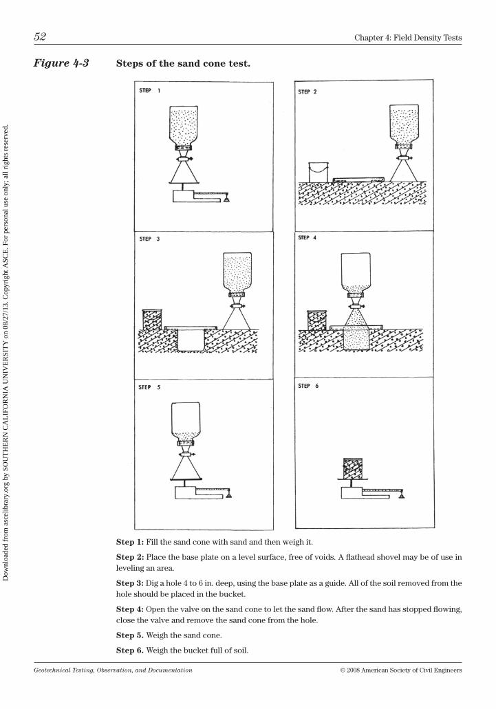
Geotechnical Testing, Observation, and Documentation © 2008 American Society of civil Engineers
52 chapter 4: Field Density tests
Figure 4-3 Steps of the sand cone test.
Step 1: Fill the sand cone with sand and then weigh it.
Step 2: Place the base plate on a level surface, free of voids. A flathead shovel may be of use in leveling an area.
Step 3: Dig a hole 4 to 6 in. deep, using the base plate as a guide. All of the soil removed from the hole should be placed in the bucket.
Step 4: open the valve on the sand cone to let the sand flow. After the sand has stopped flowing, close the valve and remove the sand cone from the hole.
Step 5. Weigh the sand cone.
Step 6. Weigh the bucket full of soil.
Dow
nloa
ded
from
asc
elib
rary
.org
by
SOU
TH
ER
N C
AL
IFO
RN
IA U
NIV
ER
SIT
Y o
n 08
/27/
13. C
opyr
ight
ASC
E. F
or p
erso
nal u
se o
nly;
all
righ
ts r
eser
ved.
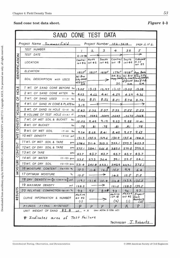
Geotechnical Testing, Observation, and Documentation © 2008 American Society of civil Engineers
chapter 4: Field Density tests 53
Sand cone test data sheet. Figure 4-4
Dow
nloa
ded
from
asc
elib
rary
.org
by
SOU
TH
ER
N C
AL
IFO
RN
IA U
NIV
ER
SIT
Y o
n 08
/27/
13. C
opyr
ight
ASC
E. F
or p
erso
nal u
se o
nly;
all
righ
ts r
eser
ved.
Geotechnical Testing, Observation, and Documentation © 2008 American Society of civil Engineers
54 chapter 4: Field Density tests
the sand to fill the hole and cone completely. Do not tap the cone or funnel during the test. Also be sure that there is no vibratory equipment working close enough to vibrate the sand, which could lower the test result because more sand would vibrate into the hole than would normally take place from gravity flow only. After the sand has completely stopped flowing, turn the valve off and remove the sand cone from the hole.
Steps 5 and 6
Weigh both the sand cone and the bucket of soil. insert the weight of the bucket and soil (#7) and the weight of remaining sand and cone (#2) on the data sheet.
remove about 250 to 300 g of material from the bucket and place it in a pan or container for the moisture burn-out. Weigh the sample and record the value as the wet weight and pan (#11). When the sample has completely dried, obtain a weight and insert the value as the weight of dry soil and tare (#12) on the data sheet.
calculations for both the in-place moisture content and dry density of the soil can now be made (see steps listed in Figure 4-4 for calculations).
Refer to “Test Number 1” Results on the Sand Cone Test Data Sheet
to calculate the percent compaction the right Proctor must be chosen. care must be taken in matching the soil type at the density test location with the laboratory Proctor of the same description. For this test a native yellow brown, silty sand (Sm) with a maximum density of 128.3 pcf (lb/ft3) and an optimum moisture of 10.5% is used (#19 and #17, respectively).
using the dry density of 119.1 pcf from the field test (#18), the resulting degree of compaction is 93% (#20). Given a recommended degree of compaction of 90% from the project geotechnical report, then the test passed.
With a moisture content of 10.2% obtained from the moisture burn-out (#16) and given that the geotechnical report recommended that the moisture content falls between –1% and +3% of optimum, test number 1’s moisture content is also acceptable since the optimum for the soil is 10.5% (#17, from the Proctor).
Test Biases
Some soils—when placed in an over-optimum moisture condition, or when con-siderable “pumping” is present—may be hard to test accurately with a sand cone. this is because after a test hole is dug in these soils, often before the silica sand can fill the hole, the hole closes in enough to give a false density (higher than actual) result. A nuclear gauge may give a more dependable reading for these soil conditions.
Dow
nloa
ded
from
asc
elib
rary
.org
by
SOU
TH
ER
N C
AL
IFO
RN
IA U
NIV
ER
SIT
Y o
n 08
/27/
13. C
opyr
ight
ASC
E. F
or p
erso
nal u
se o
nly;
all
righ
ts r
eser
ved.
Geotechnical Testing, Observation, and Documentation © 2008 American Society of civil Engineers
chapter 4: Field Density tests 55
nuclear Gauge—moisture/Density test
(AStm D6938)
the nuclear gauge is now widely accepted as an accurate and quick method for taking moisture and density tests in the field. unlike the sand cone test, in which results take about 20 minutes or more to complete, nuclear gauges are computer based, allowing results to be calculated and read directly from a gauge in a minute or less. in addition, test data can be stored in the gauge’s memory, then recalled or downloaded later.
nuclear gauges typically use two sources of radioactive material: cesium-137 and americium-241:beryllium. the cesium is steel encapsulated at the tip of the “source rod,” and the americium is permanently located inside near the base of the gauge. the cesium is the source of gamma rays (used for density readings) and americium is a neutron emitter (for moisture readings).
Important! When used with care, the nuclear gauge can be safe. how-ever, it is important not to become desensitized to the dangers of radio-active material just because the radiation cannot be seen or immediately felt. Radiation exposure is cumulative, but it can be minimized by lim-iting the time and increasing the distance from the gauge during usage. Do not locate the nuclear gauge near the driver or passenger compart-ments during transport, and never do paperwork on the truck tailgate near the nuclear gauge.
Taking a Test
to perform a density test with a nuclear gauge a flat surface must be excavated (see Fig. 4-5). An advantage of the nuclear gauge is that it allows you to take a test on a slope face; the surface must be flat, but not necessarily horizontal. in con-trast, a sand cone test must always be taken on a flat and horizontal surface.
Another advantage is that a nuclear gauge can give wet density and moisture results concurrently; no moisture “burn-out” is needed as with the sand cone test—this allows for immediate dry density and compaction calculations. the appropriate laboratory maximum densities may be stored in the gauge memory, reducing the calculation for percent compaction to a simple push of a couple of buttons.
Density may be taken with the gauge in either the “backscatter” position (in which the source rod does not penetrate the ground surface) or in the “direct transmission” mode (in which the source is inserted to a desired test depth, up to 12 in. with some model gauges).
the backscatter method primarily tests the material within about 4 in. of the sur-face. taking a test in the backscatter mode may be advantageous on relatively thin (5 in. or less) layers of aggregate baserock or other granular noncohesive
Dow
nloa
ded
from
asc
elib
rary
.org
by
SOU
TH
ER
N C
AL
IFO
RN
IA U
NIV
ER
SIT
Y o
n 08
/27/
13. C
opyr
ight
ASC
E. F
or p
erso
nal u
se o
nly;
all
righ
ts r
eser
ved.
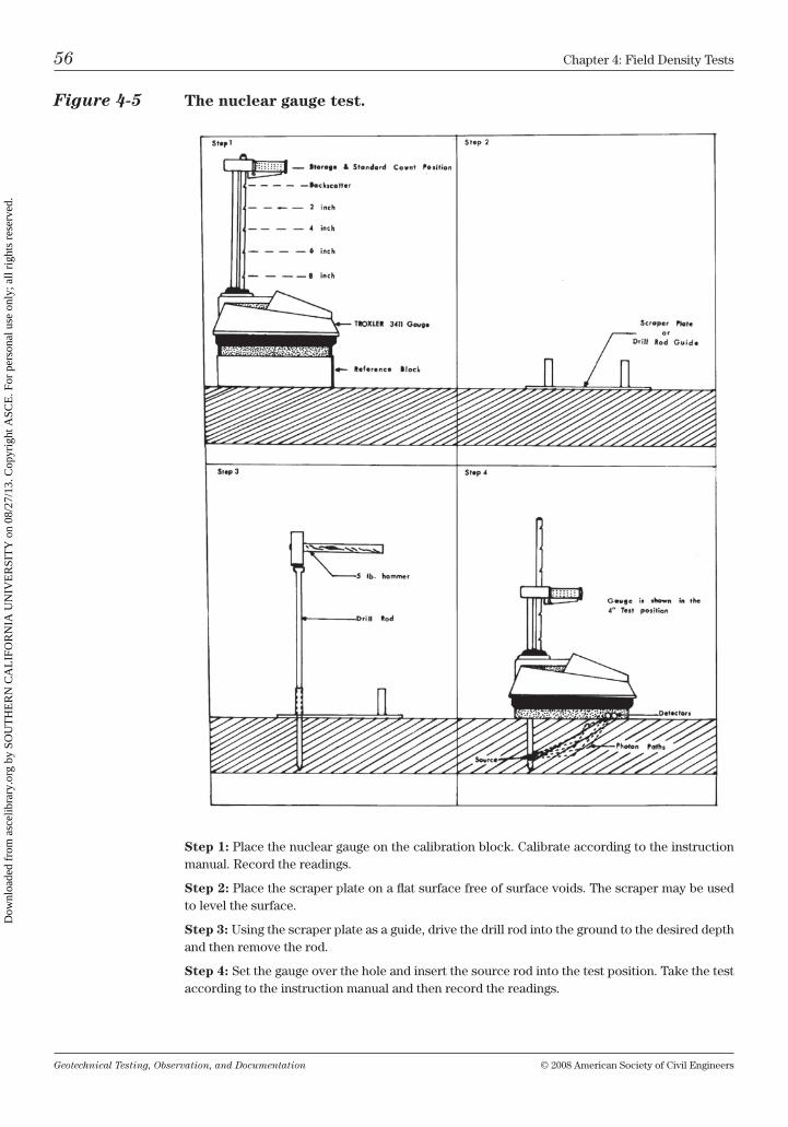
Geotechnical Testing, Observation, and Documentation © 2008 American Society of civil Engineers
56 chapter 4: Field Density tests
Figure 4-5 The nuclear gauge test.
Step 1: Place the nuclear gauge on the calibration block. calibrate according to the instruction manual. record the readings.
Step 2: Place the scraper plate on a flat surface free of surface voids. the scraper may be used to level the surface.
Step 3: using the scraper plate as a guide, drive the drill rod into the ground to the desired depth and then remove the rod.
Step 4: Set the gauge over the hole and insert the source rod into the test position. take the test according to the instruction manual and then record the readings.
Dow
nloa
ded
from
asc
elib
rary
.org
by
SOU
TH
ER
N C
AL
IFO
RN
IA U
NIV
ER
SIT
Y o
n 08
/27/
13. C
opyr
ight
ASC
E. F
or p
erso
nal u
se o
nly;
all
righ
ts r
eser
ved.
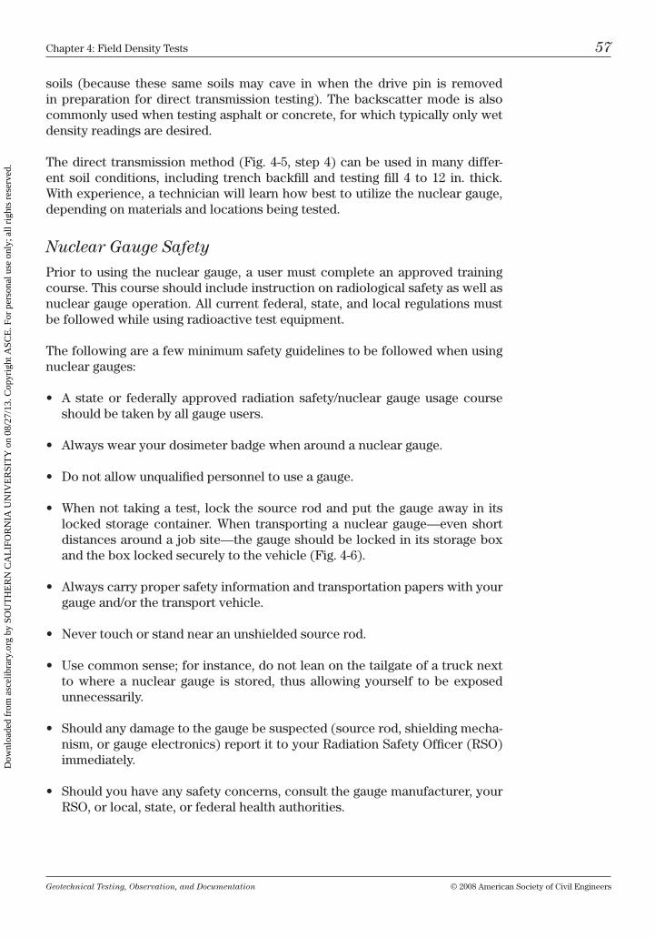
Geotechnical Testing, Observation, and Documentation © 2008 American Society of civil Engineers
chapter 4: Field Density tests 57
soils (because these same soils may cave in when the drive pin is removed in preparation for direct transmission testing). the backscatter mode is also commonly used when testing asphalt or concrete, for which typically only wet density readings are desired.
the direct transmission method (Fig. 4-5, step 4) can be used in many differ-ent soil conditions, including trench backfill and testing fill 4 to 12 in. thick. With experience, a technician will learn how best to utilize the nuclear gauge, depending on materials and locations being tested.
Nuclear Gauge Safety
Prior to using the nuclear gauge, a user must complete an approved training course. this course should include instruction on radiological safety as well as nuclear gauge operation. All current federal, state, and local regulations must be followed while using radioactive test equipment.
the following are a few minimum safety guidelines to be followed when using nuclear gauges:
• A state or federally approved radiation safety/nuclear gauge usage courseshould be taken by all gauge users.
• Alwayswearyourdosimeterbadgewhenaroundanucleargauge.
• Donotallowunqualifiedpersonneltouseagauge.
• Whennot takingatest, lockthesourcerodandput thegaugeaway in itslocked storage container. When transporting a nuclear gauge—even short distances around a job site—the gauge should be locked in its storage box and the box locked securely to the vehicle (Fig. 4-6).
• Alwayscarrypropersafetyinformationandtransportationpaperswithyourgauge and/or the transport vehicle.
• Nevertouchorstandnearanunshieldedsourcerod.
• Usecommonsense;forinstance,donotleanonthetailgateofatrucknextto where a nuclear gauge is stored, thus allowing yourself to be exposed unnecessarily.
• Shouldanydamagetothegaugebesuspected(sourcerod,shieldingmecha-nism, or gauge electronics) report it to your radiation Safety officer (rSo) immediately.
• Shouldyouhaveanysafetyconcerns,consultthegaugemanufacturer,yourrSo, or local, state, or federal health authorities.
Dow
nloa
ded
from
asc
elib
rary
.org
by
SOU
TH
ER
N C
AL
IFO
RN
IA U
NIV
ER
SIT
Y o
n 08
/27/
13. C
opyr
ight
ASC
E. F
or p
erso
nal u
se o
nly;
all
righ
ts r
eser
ved.
Geotechnical Testing, Observation, and Documentation © 2008 American Society of civil Engineers
58 chapter 4: Field Density tests
Figure 4-6 Truck-mounted storage of a nuclear gauge (demonstrated by Bob King).
it should be remembered that cesium-137 is a highly radioactive material that is potentially hazardous unless due caution and proper procedures are followed while using a nuclear gauge. When used properly—and with experience—the nuclear gauge is a valuable tool for moisture and density testing.
Test Biases
certain minerals, such as gypsum or diatomaceous and other soils, may cause the neutrons (emitted by the americium-241:beryllium source) to be absorbed in a manner that may cause the gauge to read a different moisture content than the material may actually contain. to adjust for this anomaly, a sample of the material in question should be dried in the laboratory for moisture content. the difference between the field and lab moisture can be used as a reference to “offset” the gauge to read accurate moisture for the specific material being tested.
Another case in which the moisture may read improperly is while testing trench backfill. because of the “sidewall scatter” effect of the neutrons, the moisture reading may be higher than the actual moisture content. to adjust for this inaccuracy, the gauge may be standardized in the trench (per manufacturer’s instructions) to account for sidewall scatter. typically, if the trench walls are about three feet from the gauge, no significant sidewall effect occurs.
Dow
nloa
ded
from
asc
elib
rary
.org
by
SOU
TH
ER
N C
AL
IFO
RN
IA U
NIV
ER
SIT
Y o
n 08
/27/
13. C
opyr
ight
ASC
E. F
or p
erso
nal u
se o
nly;
all
righ
ts r
eser
ved.
Geotechnical Testing, Observation, and Documentation © 2008 American Society of civil Engineers
chapter 4: Field Density tests 59
Remember: the nuclear gauge—like the sand cone—is only a tool used to help technicians confirm their observations and form opinions about the moisture and density of the material being tested. relying on their experience and judgment, technicians should watch for soil conditions that may influence the gauge’s results.
Figure 4-6 shows a gauge housed in a metal storage box. this metal storage box locks safely into place during transport. When the gauge is needed for use, the box tilts forward and then is unlocked for easy gauge removal.
chapter Questions
1. The sand cone test is a relatively new test method.A) trueb) False
2. The depth of the hole dug for a sand cone test (ASTM D1556) should be:A) 2 to 4 in.b) 6 to 8 in.c) 10 to 12 in.D) none of the above
3. After the sand has stopped flowing, but just before removing the cone from the plate, you should tap the cone and jar.A) trueb) False
4. The neutron source in the nuclear gauge is depleted uranium (ura-nium-238) and is relatively harmless.A) trueb) False
5. A sand cone test can be taken on a sloping surface.A) trueb) False
6. A nuclear density test can be performed on a sloped surface.A) trueb) False
Dow
nloa
ded
from
asc
elib
rary
.org
by
SOU
TH
ER
N C
AL
IFO
RN
IA U
NIV
ER
SIT
Y o
n 08
/27/
13. C
opyr
ight
ASC
E. F
or p
erso
nal u
se o
nly;
all
righ
ts r
eser
ved.

Geotechnical Testing, Observation, and Documentation © 2008 American Society of civil Engineers
60 chapter 4: Field Density tests
7. As long as the nuclear gauge is locked in its storage box in the rear of a pick-up truck, it is OK to sit on the tailgate near the gauge.A) trueb) False
8. Which of the following soils, or test situations, may bias or cause the gauge to give an inaccurate moisture result?A) When testing gypsiferous soilb) When testing diatomaceous soilc) When testing backfill in a 30-in.–wide trenchD) All of the aboveE) none of the above
Dow
nloa
ded
from
asc
elib
rary
.org
by
SOU
TH
ER
N C
AL
IFO
RN
IA U
NIV
ER
SIT
Y o
n 08
/27/
13. C
opyr
ight
ASC
E. F
or p
erso
nal u
se o
nly;
all
righ
ts r
eser
ved.
Geotechnical Testing, Observation, and Documentation © 2008 American Society of civil Engineers 61
Soil Engineering for the Technician
A main responsibility of the soil technician is to help confirm that the recom-mendations presented in the geotechnical report are implemented in the field during the grading and other construction processes. to properly interpret the recommendations, the technician must be familiar with soil engineering termi-nology. both trainees and more experienced field personnel can use the glos-sary in Appendix A as a quick reference.
Project Preparation
many grading recommendations in the geotechnical report are common prac-tice, such as removing debris, stockpiles, and the stripping of vegetation. mini-mum requirements typically include the removal of undocumented fill, as well as porous (collapsible) and loose or soft soils, followed by the preparation of the exposed soils by scarification, moisture conditioning, and compaction. however, each soil report is based on specific site conditions and must be read carefully. too often, technicians may become overconfident and neglect to read the geotechnical report closely, thus overlooking a recommendation that may not be typical during normal grading operations.
it is good practice for the technician to prepare for a new project by highlight-ing specific recommendations in the geotechnical report. these include the following:
• depth of removals (cut or “over-ex”);
• type of materials to be removed (such as loose, soft, porous, expansive, or highly cemented soils);
• degree of compaction recommended (which may vary with soil conditions or proposed structure type);
• moisture limits to be targeted during compaction (i.e., near optimum, 2 to 4% over optimum, etc.);
5
Dow
nloa
ded
from
asc
elib
rary
.org
by
SOU
TH
ER
N C
AL
IFO
RN
IA U
NIV
ER
SIT
Y o
n 08
/27/
13. C
opyr
ight
ASC
E. F
or p
erso
nal u
se o
nly;
all
righ
ts r
eser
ved.
Geotechnical Testing, Observation, and Documentation © 2008 American Society of civil Engineers
62 chapter 5: Soil Engineering for the technician
• placement of specific soil or material (including oversized material, expan-sive clays, gypsiferous soils, or other unique materials); and
• allotherproject-specific recommendations.
Pay careful attention to the type of soils encountered in the geotechnical report through close review of the boring and/or trench logs. compare mate-rials exposed during excavation and site grading with those described in the soils report. Any discrepancy should be discussed with the project engineer immediately.
Flatland Projects
When grading generally flat sites—after removal of unacceptable material—the degree of compaction and percent moisture content are usually the most criti-cal factors. however, prior to placing any fill, the existing ground surface must be prepared by scarification (typically 6 in. deep), moisture conditioning, and then compaction.
When placing expansive soils, the moisture content of the material is as impor-tant as the degree of compaction. many silty and clayey soils are extremely sen-sitive to moisture changes. in some silty soils (diatomaceous soils, for exam-ple), a variation of only a few percent in water content could change the soil’s dry density by as much as 5 or 10 lb/ft3 during compaction. Also, many plastic soils increase in volume (expand) with added moisture (and, conversely, shrink when dried back); therefore it is standard practice to place expansive soils in a slightly over-optimum condition, and often at a lower degree of compaction—compared with nonexpansive soils—to help limit expansion potential.
Even sandy and silty noncohesive soils generally compact better when placed at or slightly above optimum, thus lubricating the particles—as well as helping to mitigate any future settlement or consolidation caused by increases in mois-ture from landscape watering or heavy rains.
road construction
the final surface of the road section—the asphalt—depends on the materials supporting it: the aggregate base and the subgrade. the first step is the prepara-tion of the existing ground surface to create a compact, stable subgrade. often the area must be cut down to reach the proposed finish subgrade elevation, during which time rocks and/or soft pockets are often exposed. to create a homogeneous subgrade, it is important to prepare the cut surface (prior to plac-ing aggregate base) by scarifying, removing cobbles and larger rock, moisture conditioning, and then compacting. improperly prepared subgrade is often the cause of potholes, cracks, and areas of uneven pavement.
During the grading of subgrade and aggregate base course for road construction it is important not only to test for compaction, but also to observe the actions
Dow
nloa
ded
from
asc
elib
rary
.org
by
SOU
TH
ER
N C
AL
IFO
RN
IA U
NIV
ER
SIT
Y o
n 08
/27/
13. C
opyr
ight
ASC
E. F
or p
erso
nal u
se o
nly;
all
righ
ts r
eser
ved.
Geotechnical Testing, Observation, and Documentation © 2008 American Society of civil Engineers
chapter 5: Soil Engineering for the technician 63
of the compaction equipment on the road material during the compaction pro-cess. For instance, although a density test taken on the subgrade may indicate that the moisture content of the material is only a few percentage points over optimum (which is generally desirable within building areas), you may notice that the subgrade soil is moving (pumping or rolling) beneath the compaction equipment. Soft and yielding soils are not acceptable. the surface must be firm and relatively unyielding prior to paving. Soils that deflect or move can be det-rimental to pavement.
Tip: it is a good idea to walk next to the compaction equipment during the final compaction of both the finished subgrade and aggregate base surfaces to closely observe the action of the material for any movement or deflection beneath the tires or roller. before accepting a subgrade or aggregate base as finished, the surface should be “proof rolled.” A fully loaded water truck works well for proof rolling. beware that some con-tractors will try to proof roll with a partially filled truck!
often, remixing and/or drying back of the material to bring it closer to optimum, followed by recompaction, will stabilize the subgrade. however, sometimes overly wet or soft soils need to be excavated and replaced with compacted aggregate base or other acceptable material. For more severe cases of unsta-ble subgrade, stabilization may first include the placement of woven fabric or geogrid, overlain by compacted aggregate base. (See Fig. 5-1.)
Tip: Woven stabilization fabrics work quite well when used properly. however, all too often the fabrics are placed improperly and are not overlapped enough, or not loaded down with sufficient aggregate base or other material. A minimum overlap is usually 24 in., and experience has shown that less than 18 in. of aggregate base cover is often inad-equate.
the technician should also watch the finished baserock surface for any nesting or segregation of the material. Sometimes surface areas or pockets containing mostly gravel with few or no fines may occur. this segregation (nesting) may be due in part to too much rubber-tire traffic allowed on the baserock prior to paving. Surface areas that are not homogeneous or fail to meet gradation stan-dards should be remixed and recompacted.
Density testing of aggregate base can sometimes be tricky. if a baserock sec-tion is relatively thin, 5 in. or less, better test results may be obtained by using the “backscatter” mode of a nuclear gauge. many times when the drill rod is being driven in (to prepare for a “direct transmission” test), the baserock may move and become too disturbed to accurately test. using the backscatter mode will not disturb the aggregate base, and silica sand (or aggregate base fines) may be used to fill in any minor surface voids, thus providing a more reliable test. through experience, a technician will develop a better feel for which test method may work best in a specific situation.
Dow
nloa
ded
from
asc
elib
rary
.org
by
SOU
TH
ER
N C
AL
IFO
RN
IA U
NIV
ER
SIT
Y o
n 08
/27/
13. C
opyr
ight
ASC
E. F
or p
erso
nal u
se o
nly;
all
righ
ts r
eser
ved.
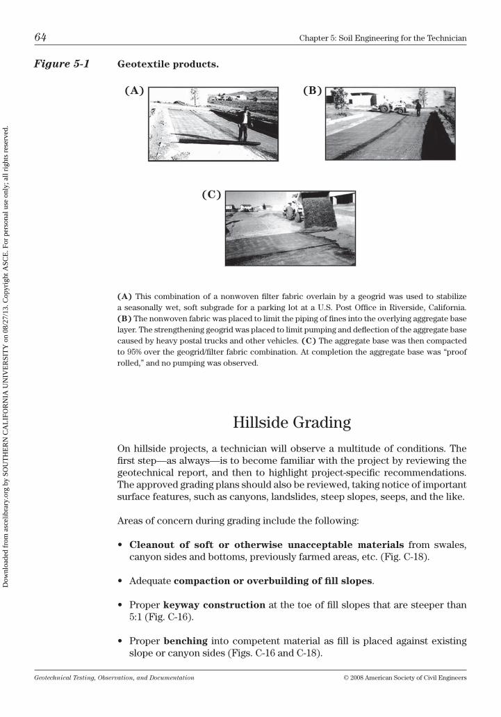
Geotechnical Testing, Observation, and Documentation © 2008 American Society of civil Engineers
64 chapter 5: Soil Engineering for the technician
hillside Grading
on hillside projects, a technician will observe a multitude of conditions. the first step—as always—is to become familiar with the project by reviewing the geotechnical report, and then to highlight project-specific recommendations. the approved grading plans should also be reviewed, taking notice of important surface features, such as canyons, landslides, steep slopes, seeps, and the like.
Areas of concern during grading include the following:
• Cleanout of soft or otherwise unacceptable materials from swales, canyon sides and bottoms, previously farmed areas, etc. (Fig. c-18).
• Adequatecompaction or overbuilding of fill slopes.
• Properkeyway construction at the toe of fill slopes that are steeper than 5:1 (Fig. c-16).
• Properbenching into competent material as fill is placed against existing slope or canyon sides (Figs. c-16 and c-18).
Figure 5-1 Geotextile products.
(A) this combination of a nonwoven filter fabric overlain by a geogrid was used to stabilize a seasonally wet, soft subgrade for a parking lot at a u.S. Post office in riverside, california. (B) the nonwoven fabric was placed to limit the piping of fines into the overlying aggregate base layer. the strengthening geogrid was placed to limit pumping and deflection of the aggregate base caused by heavy postal trucks and other vehicles. (C) the aggregate base was then compacted to 95% over the geogrid/filter fabric combination. At completion the aggregate base was “proof rolled,” and no pumping was observed.
(A) (B)
(C)
Dow
nloa
ded
from
asc
elib
rary
.org
by
SOU
TH
ER
N C
AL
IFO
RN
IA U
NIV
ER
SIT
Y o
n 08
/27/
13. C
opyr
ight
ASC
E. F
or p
erso
nal u
se o
nly;
all
righ
ts r
eser
ved.
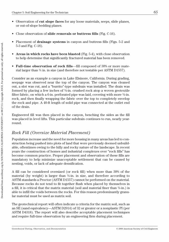
Geotechnical Testing, Observation, and Documentation © 2008 American Society of civil Engineers
chapter 5: Soil Engineering for the technician 65
• Observationofcut slope faces for any loose materials, seeps, slide planes, or out-of-slope bedding planes.
• Closeobservationofslide removals or buttress fills (Fig. c-16).
• Placementofdrainage systems in canyon and buttress fills (Figs. 5-2 and 5-3 and Fig. c-18).
• Areas in which rocks have been blasted (Fig. 5-4), with close observation to help determine that significantly fractured material has been removed.
• Full-time observation of rock fills—fill composed of 30% or more mate-rial larger than ¾ in. in size (and therefore not testable per AStm D1557).
consider as an example a canyon in lake Elsinore, california. During grading, seepage was observed near the top of the canyon. the canyon was cleaned out, a slot was cut, and a “burrito”-type subdrain was installed. the drain was formed by placing a few inches of ¾-in. crushed rock atop a woven geotextile filter fabric, on which a 6-in. perforated pipe was laid, covering with more ¾-in. rock, and then finally wrapping the fabric over the top to completely envelop the rock and pipe. A 40-ft length of solid pipe was connected at the outlet end of the drain.
Engineered fill was then placed in the canyon, benching the sides as the fill was placed in level lifts. this particular subdrain continues to run, nearly year-round.
Rock Fill (Oversize Material Placement)
Population increase and the need for more housing in many areas has led to con-struction being pushed into plots of land that were previously deemed unbuild-able, oftentimes owing to the hilly and rocky nature of the landscape. in recent years the construction of homes and industrial complexes over “rock fills” has become common practice. Proper placement and observation of these fills are mandatory to help minimize unacceptable settlement that can be caused by nesting, voids, or lack of adequate densification.
A fill can be considered oversized (or rock fill) when more than 30% of the material (by weight) is larger than ¾-in. in size, and therefore according to AStm standards a Proctor (AStm D1557) cannot be performed on the material. because rocks do not tend to fit together flush when placed by themselves in a fill, it is critical that the matrix material (soil and material finer than ¾-in.) is able to infill the voids between the rocks. For this reason predominantly granu-lar material must be used as matrix soil.
the geotechnical report will often indicate a criteria for the matrix soil, such as an SE (sand equivalency—AStm D2914) of 32 or greater or a nonplastic Pi (per AStm D4318). the report will also describe acceptable placement techniques and require full-time observation by an engineering firm during placement.
Dow
nloa
ded
from
asc
elib
rary
.org
by
SOU
TH
ER
N C
AL
IFO
RN
IA U
NIV
ER
SIT
Y o
n 08
/27/
13. C
opyr
ight
ASC
E. F
or p
erso
nal u
se o
nly;
all
righ
ts r
eser
ved.
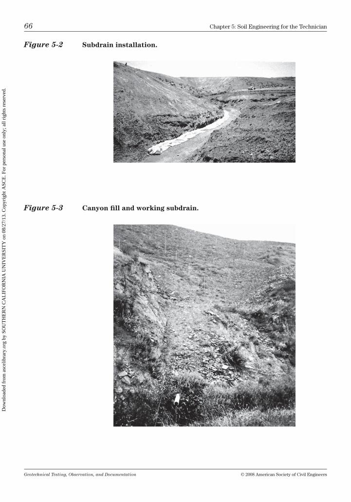
Geotechnical Testing, Observation, and Documentation © 2008 American Society of civil Engineers
66 chapter 5: Soil Engineering for the technician
Figure 5-2 Subdrain installation.
Figure 5-3 Canyon fill and working subdrain.
Dow
nloa
ded
from
asc
elib
rary
.org
by
SOU
TH
ER
N C
AL
IFO
RN
IA U
NIV
ER
SIT
Y o
n 08
/27/
13. C
opyr
ight
ASC
E. F
or p
erso
nal u
se o
nly;
all
righ
ts r
eser
ved.
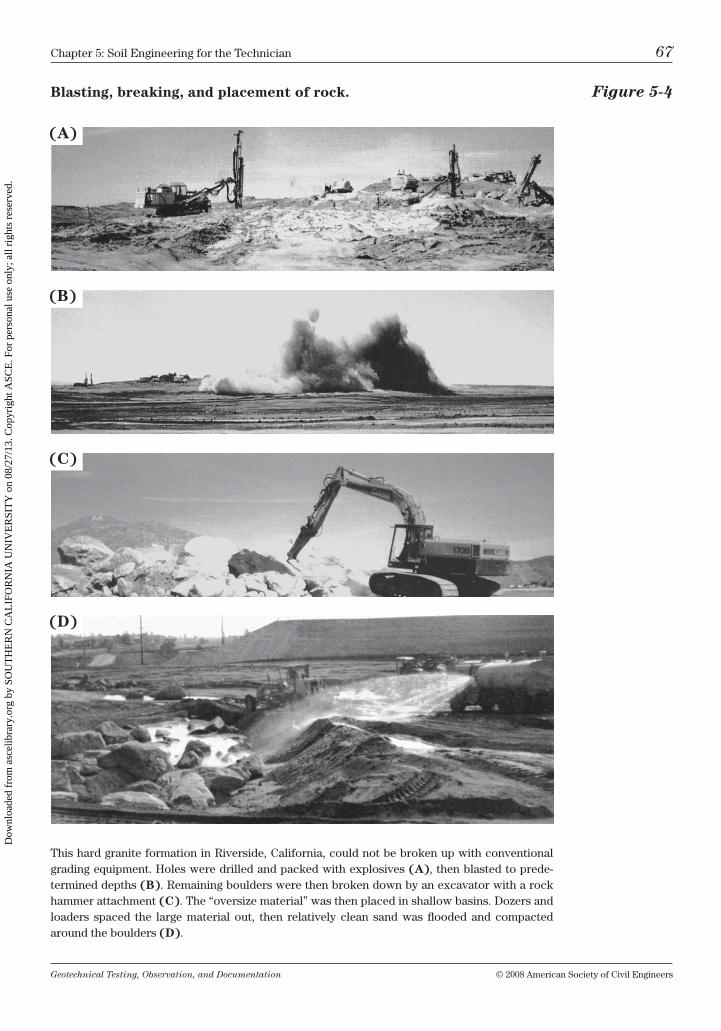
Geotechnical Testing, Observation, and Documentation © 2008 American Society of civil Engineers
chapter 5: Soil Engineering for the technician 67
Blasting, breaking, and placement of rock. Figure 5-4
this hard granite formation in riverside, california, could not be broken up with conventional grading equipment. holes were drilled and packed with explosives (A), then blasted to prede-termined depths (B). remaining boulders were then broken down by an excavator with a rock hammer attachment (C). the “oversize material” was then placed in shallow basins. Dozers and loaders spaced the large material out, then relatively clean sand was flooded and compacted around the boulders (D).
(A)
(B)
(C)
(D)
Dow
nloa
ded
from
asc
elib
rary
.org
by
SOU
TH
ER
N C
AL
IFO
RN
IA U
NIV
ER
SIT
Y o
n 08
/27/
13. C
opyr
ight
ASC
E. F
or p
erso
nal u
se o
nly;
all
righ
ts r
eser
ved.
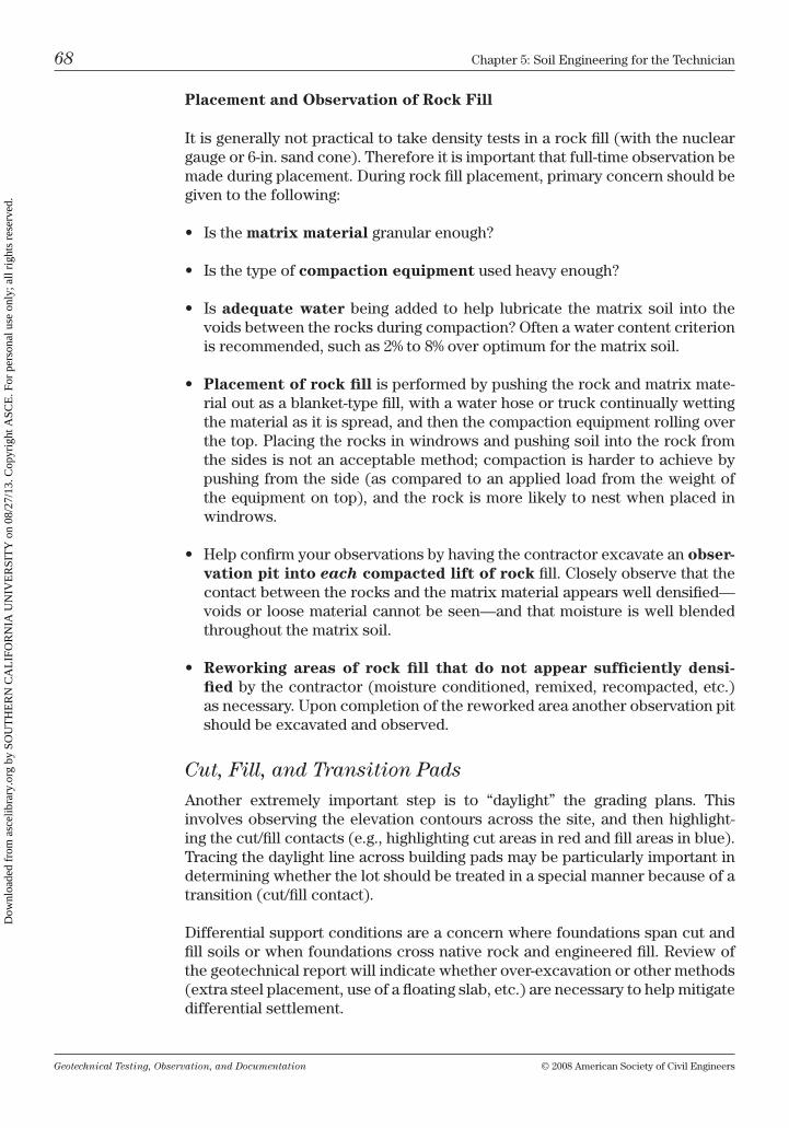
Geotechnical Testing, Observation, and Documentation © 2008 American Society of civil Engineers
68 chapter 5: Soil Engineering for the technician
Placement and Observation of Rock Fill
it is generally not practical to take density tests in a rock fill (with the nuclear gauge or 6-in. sand cone). therefore it is important that full-time observation be made during placement. During rock fill placement, primary concern should be given to the following:
• Isthematrix material granular enough?
• Isthetypeofcompaction equipment used heavy enough?
• Isadequate water being added to help lubricate the matrix soil into the voids between the rocks during compaction? often a water content criterion is recommended, such as 2% to 8% over optimum for the matrix soil.
• Placement of rock fill is performed by pushing the rock and matrix mate-rial out as a blanket-type fill, with a water hose or truck continually wetting the material as it is spread, and then the compaction equipment rolling over the top. Placing the rocks in windrows and pushing soil into the rock from the sides is not an acceptable method; compaction is harder to achieve by pushing from the side (as compared to an applied load from the weight of the equipment on top), and the rock is more likely to nest when placed in windrows.
• Helpconfirmyourobservationsbyhavingthecontractorexcavateanobser-vation pit into each compacted lift of rock fill. closely observe that the contact between the rocks and the matrix material appears well densified—voids or loose material cannot be seen—and that moisture is well blended throughout the matrix soil.
• Reworking areas of rock fill that do not appear sufficiently densi-fied by the contractor (moisture conditioned, remixed, recompacted, etc.) as necessary. upon completion of the reworked area another observation pit should be excavated and observed.
Cut, Fill, and Transition Pads
Another extremely important step is to “daylight” the grading plans. this involves observing the elevation contours across the site, and then highlight-ing the cut/fill contacts (e.g., highlighting cut areas in red and fill areas in blue). tracing the daylight line across building pads may be particularly important in determining whether the lot should be treated in a special manner because of a transition (cut/fill contact).
Differential support conditions are a concern where foundations span cut and fill soils or when foundations cross native rock and engineered fill. review of the geotechnical report will indicate whether over-excavation or other methods (extra steel placement, use of a floating slab, etc.) are necessary to help mitigate differential settlement.
Dow
nloa
ded
from
asc
elib
rary
.org
by
SOU
TH
ER
N C
AL
IFO
RN
IA U
NIV
ER
SIT
Y o
n 08
/27/
13. C
opyr
ight
ASC
E. F
or p
erso
nal u
se o
nly;
all
righ
ts r
eser
ved.
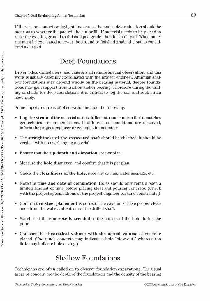
Geotechnical Testing, Observation, and Documentation © 2008 American Society of civil Engineers
chapter 5: Soil Engineering for the technician 69
if there is no contact or daylight line across the pad, a determination should be made as to whether the pad will be cut or fill. if material needs to be placed to raise the existing ground to finished pad grade, then it is a fill pad. When mate-rial must be excavated to lower the ground to finished grade, the pad is consid-ered a cut pad.
Deep Foundations
Driven piles, drilled piers, and caissons all require special observation, and this work is usually carefully coordinated with the project engineer. Although shal-low foundations may depend wholly on the bearing material, deeper founda-tions may gain support from friction and/or bearing. therefore during the drill-ing of shafts for deep foundations it is critical to log the soil and rock strata accurately.
Some important areas of observation include the following:
• Log the strata of the material as it is drilled into and confirm that it matches geotechnical recommendations. if different soil conditions are observed, inform the project engineer or geologist immediately.
• Thestraightness of the excavated shaft should be checked; it should be vertical with no overhanging material.
• Ensurethatthetip depth and elevation are per plan.
• Measurethehole diameter, and confirm that it is per plan.
• Checkthecleanliness of the hole; note any caving, water seepage, etc.
• Notethetime and date of completion. holes should only remain open a limited amount of time before placing steel and pouring concrete. (check with the project specifications or the project engineer for time constraints.)
• Confirmthatsteel placement is correct: the cage must have proper clear-ance from the walls and bottom of the drilled shaft.
• Watchthat theconcrete is tremied to the bottom of the hole during the pour.
• Compare the theoretical volume with the actual volume of concrete placed. (too much concrete may indicate a hole “blow-out,” whereas too little may indicate hole caving.)
Shallow Foundations
technicians are often called on to observe foundation excavations. the usual areas of concern are the depth of the foundations and the density of the bearing
Dow
nloa
ded
from
asc
elib
rary
.org
by
SOU
TH
ER
N C
AL
IFO
RN
IA U
NIV
ER
SIT
Y o
n 08
/27/
13. C
opyr
ight
ASC
E. F
or p
erso
nal u
se o
nly;
all
righ
ts r
eser
ved.
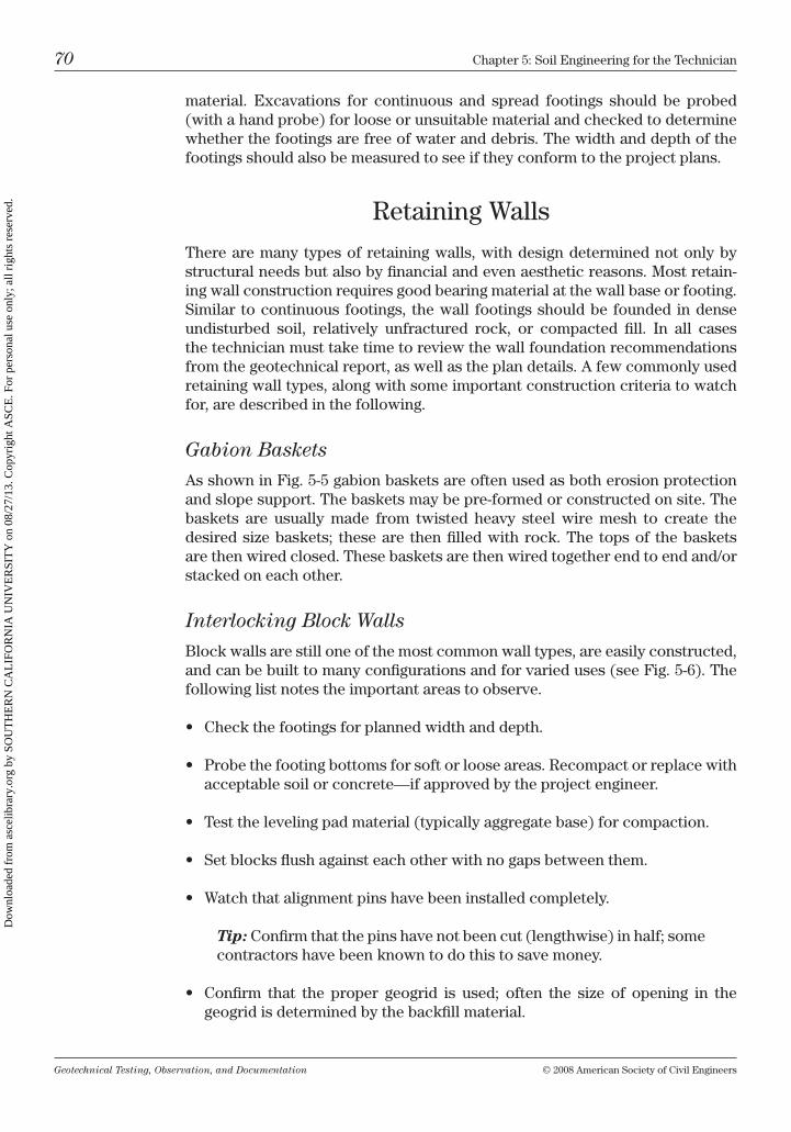
Geotechnical Testing, Observation, and Documentation © 2008 American Society of civil Engineers
70 chapter 5: Soil Engineering for the technician
material. Excavations for continuous and spread footings should be probed (with a hand probe) for loose or unsuitable material and checked to determine whether the footings are free of water and debris. the width and depth of the footings should also be measured to see if they conform to the project plans.
retaining Walls
there are many types of retaining walls, with design determined not only by structural needs but also by financial and even aesthetic reasons. most retain-ing wall construction requires good bearing material at the wall base or footing. Similar to continuous footings, the wall footings should be founded in dense undisturbed soil, relatively unfractured rock, or compacted fill. in all cases the technician must take time to review the wall foundation recommendations from the geotechnical report, as well as the plan details. A few commonly used retaining wall types, along with some important construction criteria to watch for, are described in the following.
Gabion Baskets
As shown in Fig. 5-5 gabion baskets are often used as both erosion protection and slope support. the baskets may be pre-formed or constructed on site. the baskets are usually made from twisted heavy steel wire mesh to create the desired size baskets; these are then filled with rock. the tops of the baskets are then wired closed. these baskets are then wired together end to end and/or stacked on each other.
Interlocking Block Walls
block walls are still one of the most common wall types, are easily constructed, and can be built to many configurations and for varied uses (see Fig. 5-6). the following list notes the important areas to observe.
• Checkthefootingsforplannedwidthanddepth.
• Probethefootingbottomsforsoftorlooseareas.Recompactorreplacewithacceptable soil or concrete—if approved by the project engineer.
• Testthelevelingpadmaterial(typicallyaggregatebase)forcompaction.
• Setblocksflushagainsteachotherwithnogapsbetweenthem.
• Watchthatalignmentpinshavebeeninstalledcompletely.
Tip: confirm that the pins have not been cut (lengthwise) in half; some contractors have been known to do this to save money.
• Confirm that the proper geogrid is used; often the size of opening in thegeogrid is determined by the backfill material.
Dow
nloa
ded
from
asc
elib
rary
.org
by
SOU
TH
ER
N C
AL
IFO
RN
IA U
NIV
ER
SIT
Y o
n 08
/27/
13. C
opyr
ight
ASC
E. F
or p
erso
nal u
se o
nly;
all
righ
ts r
eser
ved.
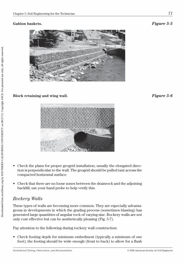
Geotechnical Testing, Observation, and Documentation © 2008 American Society of civil Engineers
chapter 5: Soil Engineering for the technician 71
Gabion baskets. Figure 5-5
Block retaining and wing wall. Figure 5-6
• Checktheplansforpropergeogridinstallation;usuallytheelongateddirec-tion is perpendicular to the wall. the geogrid should be pulled taut across the compacted horizontal surface.
• Checkthattherearenoloosezonesbetweenthedrainrockandtheadjoiningbackfill; use your hand probe to help verify this.
Rockery Walls
these types of walls are becoming more common. they are especially advanta-geous in developments in which the grading process (sometimes blasting) has generated large quantities of angular rock of varying size. rockery walls are not only cost effective but can be aesthetically pleasing (Fig. 5-7).
Pay attention to the following during rockery wall construction:
• Checkfootingdepthforminimumembedment(typicallyaminimumofonefoot); the footing should be wide enough (front to back) to allow for a flush
Dow
nloa
ded
from
asc
elib
rary
.org
by
SOU
TH
ER
N C
AL
IFO
RN
IA U
NIV
ER
SIT
Y o
n 08
/27/
13. C
opyr
ight
ASC
E. F
or p
erso
nal u
se o
nly;
all
righ
ts r
eser
ved.
Geotechnical Testing, Observation, and Documentation © 2008 American Society of civil Engineers
72 chapter 5: Soil Engineering for the technician
fit at the face of the base rock or rocks. check to see that the back cut is free of loose material and is laid back at a safe gradient prior to placing the filter fabric.
• Ifaperforateddrainpipeisplacedalongthebottombackofthewall,checkto see that the perforations are facing downward—allowing the water to flow up into the pipe, but limiting the silting-up of the pipe with fines.
• As the wall is being built, check for the proper batter (incline into theslope).
• Watchforthespecifiedsizeofrocksandthattheyareangularandplacedaccording to recommendations. the long dimensions of the rocks should be placed perpendicular to the wall, and each rock should bear on two rocks below. if rocks are double stacked, the larger rock shall be at the face of the wall.
• Thedrainrockplacedbetweenthebackofthewallandthefilterfabricshallbe free draining and is usually 1.5 to 6 in. in size.
Reinforced Concrete Walls
For reinforced concrete walls, the following are of importance:
• Checkfootingsforplannedwidthanddepth.
• Probethebottomstofindanysoftorlooseareas.Deepenfootingsthroughpoor soil into acceptable material per the geotechnical report.
• Closelyobservethebottoms(andsides)offootingexcavationsforexpansivesoils (which are typically unacceptable).
Figure 5-7 Two-level rockery wall.
Photo courtesy of robert Delk
Dow
nloa
ded
from
asc
elib
rary
.org
by
SOU
TH
ER
N C
AL
IFO
RN
IA U
NIV
ER
SIT
Y o
n 08
/27/
13. C
opyr
ight
ASC
E. F
or p
erso
nal u
se o
nly;
all
righ
ts r
eser
ved.
Geotechnical Testing, Observation, and Documentation © 2008 American Society of civil Engineers
chapter 5: Soil Engineering for the technician 73
• Watchforfootingbottomsthatspancutandfillsoils,orforfoundationsthatcross native rock and engineered fill. in these cases consult the project engi-neer to determine whether over-excavation or other methods are necessary to mitigate the potential of differential settlement.
• Priortoplacingsteel,ensurethatfootingsarefreeofwater,ice,snow,loosematerial, and any other debris.
the technician’s Steps to Success
Geotechnical technicians gain much of their on-the-job experience from other senior technicians and engineers, as there are currently no graduate degrees tailored for the engineering technician. by following these guidelines a techni-cian can be respected and effective on the job.
1. Be safe: never sacrifice job safety for job expediency.
2. Always prepare: one way to gain the respect of the contractor and your associates is to thoroughly understand the project.
• Readandunderstandthegeotechnicalreport.
• Studytheplans.
• Meetwiththeprojectengineertoreviewtheproject.
• Setupafieldfile.
• Walktheproject:Readthegradestakes,lookatsoilandrockincutareas,visualize how the contractor might grade the site, and note any areas of concern.
• ObtainProctorsamples.
• Haveapre-jobmeeting(preferablyonsite)andtakegoodnotes.
3. Be professional:
• Beontimetotheprojecteveryday.
• Make your decisions based on the plans and specifications and beconsistent.
• Bereadybyhavingthenecessarysafetyandtestequipmentandsupplieson hand.
Dow
nloa
ded
from
asc
elib
rary
.org
by
SOU
TH
ER
N C
AL
IFO
RN
IA U
NIV
ER
SIT
Y o
n 08
/27/
13. C
opyr
ight
ASC
E. F
or p
erso
nal u
se o
nly;
all
righ
ts r
eser
ved.
Geotechnical Testing, Observation, and Documentation © 2008 American Society of civil Engineers
74 chapter 5: Soil Engineering for the technician
4. Document:
• Filloutadailyfieldreport,anddocumentallworkperformed;documentsite meetings and personnel present and all related job activities.
• Keepapersonaldiaryofyouractivitiesonsite.
• Takepictures(andvideosifnecessary).
• Reviewpreviousdocumentation(checkwhethertestfailureshavebeenretested, whether lab test information is current, etc.).
5. Communicate:
• Discussthejobwithyoursupervisororprojectengineerdaily.
• Communicatewiththejobforemanorsuperintendentdaily.
• Beproactive;trytoforeseeproblemsanddiscusstheminadvance.
• Shouldyouspotaproblemthatwasmissedearlierinthejob,donotignoreit. take corrective measures; unresolved problems should not be put off.
• Planahead,andaskforhelpwhenneeded.
• Shouldyouhavetoleavethejobtoworkonanotherproject,meetwiththe replacement technician and do a complete update and review.
6. Take pride in your work:
• Develop your career with certification programs (federal, county, andlocal) and continuing education. Some important certification programs include those offered by
• NICET(NationalInstituteforCertificationinEngineeringTechnologies),
• ACI(AmericanConcreteInstitute),and
• ICC(InternationalCodeCouncil;formerlyICBO).
• Maintainyourtestingandsamplingequipmentingoodworkingorder.
• Washyourvehicle—itisthefirstthingseenwhenyouarriveonsite.
Dow
nloa
ded
from
asc
elib
rary
.org
by
SOU
TH
ER
N C
AL
IFO
RN
IA U
NIV
ER
SIT
Y o
n 08
/27/
13. C
opyr
ight
ASC
E. F
or p
erso
nal u
se o
nly;
all
righ
ts r
eser
ved.
Geotechnical Testing, Observation, and Documentation © 2008 American Society of civil Engineers
chapter 5: Soil Engineering for the technician 75
chapter Questions
1. Minimum requirements in a geotechnical report often include the following two recommendations:A) the over-excavation of all sandy soilsb) the scarification of all existing surfaces prior to placing any fillc) removal of all undocumented fillD) the placement of fill in lifts no thicker than 12 in.
2. Expansive soils are often compacted at lower densities and higher moistures.A) trueb) False
3. Pumping or deflection of clayey soils is acceptable in roadway subgrade.A) trueb) False
4. The backscatter method of testing with a nuclear gauge should not be used when testing a thin layer of aggregate base.A) trueb) False
5. Which two conditions are not desirable across a footing bottom?A) Dense native soilb) compacted fill contacting bedrockc) cl/ch soil at under-optimumD) bedrock
6. A caisson was drilled to a depth of 20 ft, and upon completion water had seeped in and filled up 5 ft of the hole; what is not the proper action to take prior to pouring concrete?A) remeasure the hole, and then redrill it to remove slough/sediment if
necessary.b) confirm that the contractor will place a tremie to the bottom of the cais-
son during the pour.c) Pour low-slump concrete from the top of the caisson, making sure to
vibrate from the bottom of the hole during the pour.D) calculate the amount of concrete necessary to fill the caisson, with no
adjustment made for the 5 ft. of water.
Dow
nloa
ded
from
asc
elib
rary
.org
by
SOU
TH
ER
N C
AL
IFO
RN
IA U
NIV
ER
SIT
Y o
n 08
/27/
13. C
opyr
ight
ASC
E. F
or p
erso
nal u
se o
nly;
all
righ
ts r
eser
ved.
Geotechnical Testing, Observation, and Documentation © 2008 American Society of civil Engineers
76 chapter 5: Soil Engineering for the technician
7. When constructing a rockery wall, the long dimension of the rocks should be perpendicular to the wall face.A) trueb) False
Dow
nloa
ded
from
asc
elib
rary
.org
by
SOU
TH
ER
N C
AL
IFO
RN
IA U
NIV
ER
SIT
Y o
n 08
/27/
13. C
opyr
ight
ASC
E. F
or p
erso
nal u
se o
nly;
all
righ
ts r
eser
ved.
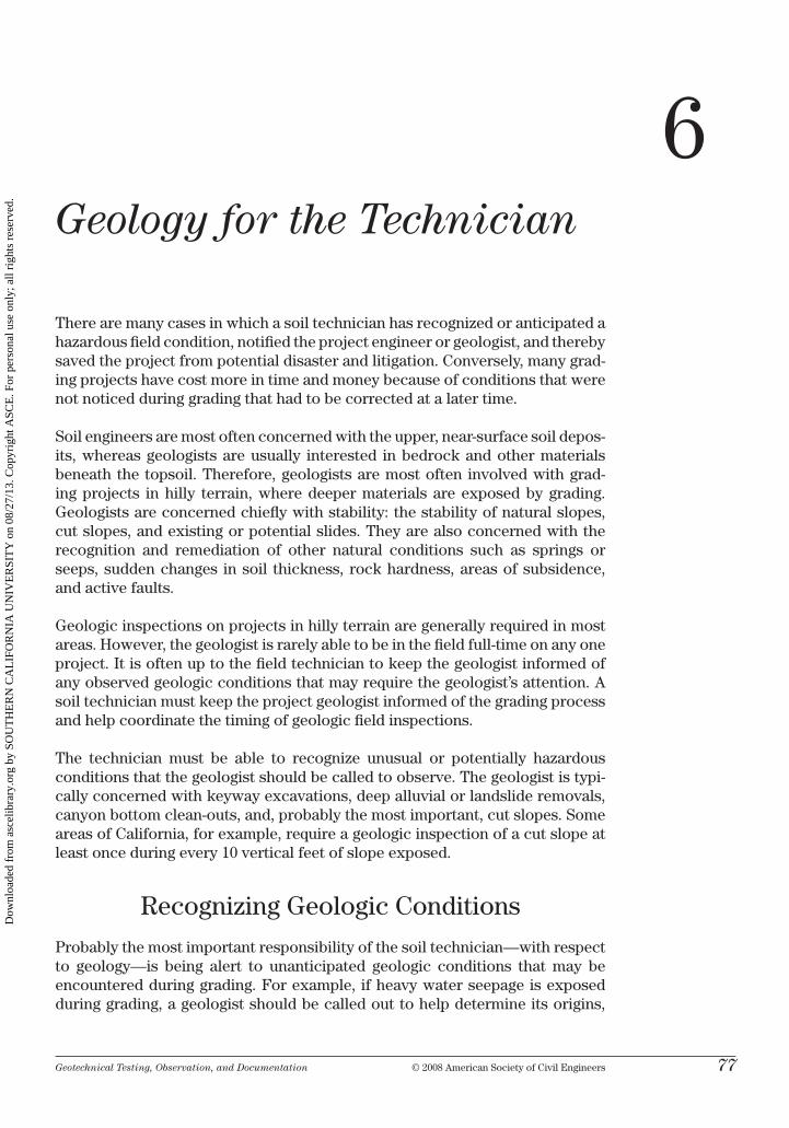
Geotechnical Testing, Observation, and Documentation © 2008 American Society of civil Engineers 77
6Geology for the Technician
there are many cases in which a soil technician has recognized or anticipated a hazardous field condition, notified the project engineer or geologist, and thereby saved the project from potential disaster and litigation. conversely, many grad-ing projects have cost more in time and money because of conditions that were not noticed during grading that had to be corrected at a later time.
Soil engineers are most often concerned with the upper, near-surface soil depos-its, whereas geologists are usually interested in bedrock and other materials beneath the topsoil. therefore, geologists are most often involved with grad-ing projects in hilly terrain, where deeper materials are exposed by grading. Geologists are concerned chiefly with stability: the stability of natural slopes, cut slopes, and existing or potential slides. they are also concerned with the recognition and remediation of other natural conditions such as springs or seeps, sudden changes in soil thickness, rock hardness, areas of subsidence, and active faults.
Geologic inspections on projects in hilly terrain are generally required in most areas. however, the geologist is rarely able to be in the field full-time on any one project. it is often up to the field technician to keep the geologist informed of any observed geologic conditions that may require the geologist’s attention. A soil technician must keep the project geologist informed of the grading process and help coordinate the timing of geologic field inspections.
the technician must be able to recognize unusual or potentially hazardous conditions that the geologist should be called to observe. the geologist is typi-cally concerned with keyway excavations, deep alluvial or landslide removals, canyon bottom clean-outs, and, probably the most important, cut slopes. Some areas of california, for example, require a geologic inspection of a cut slope at least once during every 10 vertical feet of slope exposed.
recognizing Geologic conditions
Probably the most important responsibility of the soil technician—with respect to geology—is being alert to unanticipated geologic conditions that may be encountered during grading. For example, if heavy water seepage is exposed during grading, a geologist should be called out to help determine its origins,
Dow
nloa
ded
from
asc
elib
rary
.org
by
SOU
TH
ER
N C
AL
IFO
RN
IA U
NIV
ER
SIT
Y o
n 08
/27/
13. C
opyr
ight
ASC
E. F
or p
erso
nal u
se o
nly;
all
righ
ts r
eser
ved.
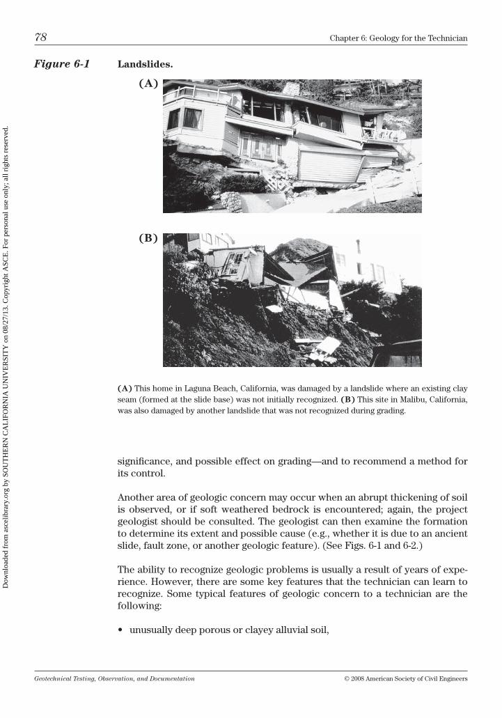
Geotechnical Testing, Observation, and Documentation © 2008 American Society of civil Engineers
78 chapter 6: Geology for the technician
significance, and possible effect on grading—and to recommend a method for its control.
Another area of geologic concern may occur when an abrupt thickening of soil is observed, or if soft weathered bedrock is encountered; again, the project geologist should be consulted. the geologist can then examine the formation to determine its extent and possible cause (e.g., whether it is due to an ancient slide, fault zone, or another geologic feature). (See Figs. 6-1 and 6-2.)
the ability to recognize geologic problems is usually a result of years of expe-rience. however, there are some key features that the technician can learn to recognize. Some typical features of geologic concern to a technician are the following:
• unusuallydeepporousorclayeyalluvialsoil,
Figure 6-1 Landslides.
(A) this home in laguna beach, california, was damaged by a landslide where an existing clay seam (formed at the slide base) was not initially recognized. (B) this site in malibu, california, was also damaged by another landslide that was not recognized during grading.
(A)
(B)
Dow
nloa
ded
from
asc
elib
rary
.org
by
SOU
TH
ER
N C
AL
IFO
RN
IA U
NIV
ER
SIT
Y o
n 08
/27/
13. C
opyr
ight
ASC
E. F
or p
erso
nal u
se o
nly;
all
righ
ts r
eser
ved.
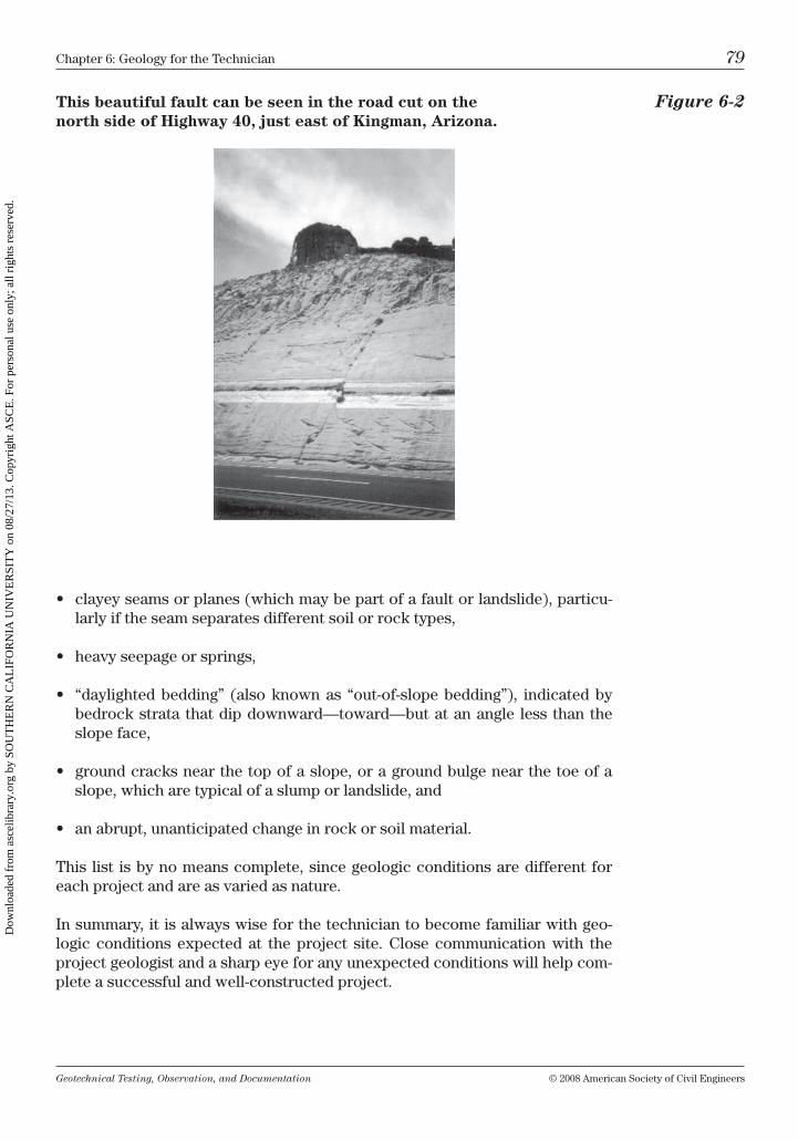
Geotechnical Testing, Observation, and Documentation © 2008 American Society of civil Engineers
chapter 6: Geology for the technician 79
This beautiful fault can be seen in the road cut on the Figure 6-2 north side of Highway 40, just east of Kingman, Arizona.
• clayeyseamsorplanes(whichmaybepartofafaultorlandslide),particu-larly if the seam separates different soil or rock types,
• heavyseepageorsprings,
• “daylightedbedding” (alsoknownas “out-of-slopebedding”), indicatedbybedrock strata that dip downward—toward—but at an angle less than the slope face,
• groundcracksnearthetopofaslope,oragroundbulgenearthetoeofaslope, which are typical of a slump or landslide, and
• anabrupt,unanticipatedchangeinrockorsoilmaterial.
this list is by no means complete, since geologic conditions are different for each project and are as varied as nature.
in summary, it is always wise for the technician to become familiar with geo-logic conditions expected at the project site. close communication with the project geologist and a sharp eye for any unexpected conditions will help com-plete a successful and well-constructed project.
Dow
nloa
ded
from
asc
elib
rary
.org
by
SOU
TH
ER
N C
AL
IFO
RN
IA U
NIV
ER
SIT
Y o
n 08
/27/
13. C
opyr
ight
ASC
E. F
or p
erso
nal u
se o
nly;
all
righ
ts r
eser
ved.
Geotechnical Testing, Observation, and Documentation © 2008 American Society of civil Engineers
80 chapter 6: Geology for the technician
chapter Questions
1. Which of the following areas should a geologist be asked to look at?A) keyway excavationsb) cut slopesc) Footing excavationsD) A and cE) A and b
2. It is not the technicians’ responsibility to be aware of geologic conditions.A) trueb) False
3. Daylighted bedding may be observed as strata in a cut slope that dips into the slope face.A) trueb) False
Dow
nloa
ded
from
asc
elib
rary
.org
by
SOU
TH
ER
N C
AL
IFO
RN
IA U
NIV
ER
SIT
Y o
n 08
/27/
13. C
opyr
ight
ASC
E. F
or p
erso
nal u
se o
nly;
all
righ
ts r
eser
ved.
Geotechnical Testing, Observation, and Documentation © 2008 American Society of civil Engineers 81
7Project Management for the Technician
the work a technician performs in the field is extremely valuable. As a techni-cian, you are the eyes of the project engineer or geologist, observing and doc-umenting the work performed by the grading contractor on the project. you must keep written records of your observations, manage your field work, and maintain continual contact with the construction team—the project engineer, contractor, and other involved personnel.
the range of work a technician will perform during each project can be divided into three general phases: project preparation, grading observation and test-ing, and the documentation of data for the final report.
Project Preparation
before beginning actual field work on a new project, technicians must become familiar with the grading contractor’s scope of work and prepare for the work they must perform during the course of the project. A discussion with the proj-ect manager (engineer, geologist, or supervisor) is a good place to start. Some important factors to consider are the project duration, whether the job is to be full or part time, and the budget estimate. the planned budget may include such items as an estimate of the number and type of testing to be performed (both field and lab), hours of field time and number of field personnel, and any special field equipment necessary to complete the job.
one of the most important preparations a technician should make is to carefully read the geotechnical report and highlight important portions of the recommen-dations. key points to highlight include the following:
• Noteanysoils thatmayrequirespecialhandling,suchasexpansiveclays,porous silts, diatomaceous, gypsiferous, organic, and any other site-specific soils.
• Highlightthedegreeofcompactionrequired,sincecompactionrecommen-dations often vary depending on soil type or usage (deeper fill, subgrade, aggregate base, expansive, etc.).
Dow
nloa
ded
from
asc
elib
rary
.org
by
SOU
TH
ER
N C
AL
IFO
RN
IA U
NIV
ER
SIT
Y o
n 08
/27/
13. C
opyr
ight
ASC
E. F
or p
erso
nal u
se o
nly;
all
righ
ts r
eser
ved.
Geotechnical Testing, Observation, and Documentation © 2008 American Society of civil Engineers
82 chapter 7: Project management for the technician
• Notethemoisturerequirements,whichmayalsovarywiththedifferentsitesoils.
• Watchforkeyways,buttressfills,slideremovals,subdrainplacements,andany other project-specific construction (as detailed in Figs. c-16 and c-18).
• Plantoobserveallexcavationsfortransitionlots(Fig.C-17),cementedsoils,and removal of stockpiles, nonengineered fill, old foundations, trees, etc.
Also while reviewing the geotechnical report, familiarize yourself with the boring or trench logs to better understand the various soils present on site, as well as their locations and depths. Whenever possible, review the structural plans and note the location and types of proposed structures, paying atten-tion to foundation types, footing depths, and steel and concrete specifications. Shortly before the job is to begin, a “pre-grade” (or pre-con) meeting should be held; representatives from the developer, the grading contractor, the civil engi-neer or architect, the soils engineer, and the lead technician should attend this meeting. this is the best time to discuss job-related concerns. Do not assume that everybody is “on the same page”; the more thorough the pre-grade meeting is, the less likely it is for there to be any surprises during the project.
the pre-grade meeting is the time to remind the contractor of any unusual or special recommendations and to carefully explain the project geotechnical rec-ommendations. important points of discussion at the pre-grade meeting may include the following:
• Discussthecontractor’s“planofattack,”typeofgradingequipment,orderofareas to be graded, time frame to complete grading, etc.
• Closelyreviewthegradingplans.
• Discusswiththecontractor(especiallythesiteforeman)therecommenda-tions set forth in the geotechnical report, such as compaction and moisture requirements, benching and keying details, over-excavation or removals, and any other special project requirements.
• Reviewjobsafetyrequirements.Forexample,besurethatnearbyequipmentis to be stopped while you are taking a density test and that no testing shall be requested inside an unsafe trench.
Although contractors are supposed to bid a job based on the project recom-mendations, they can misunderstand an important recommendation or may not fully understand site soil conditions. hence it always helps to review the report and plans with them, thereby avoiding errors resulting from miscommunication and misconceptions.
Finally, it is a good habit to fill out a project data sheet similar to the one shown in Fig. 7-1.
Dow
nloa
ded
from
asc
elib
rary
.org
by
SOU
TH
ER
N C
AL
IFO
RN
IA U
NIV
ER
SIT
Y o
n 08
/27/
13. C
opyr
ight
ASC
E. F
or p
erso
nal u
se o
nly;
all
righ
ts r
eser
ved.
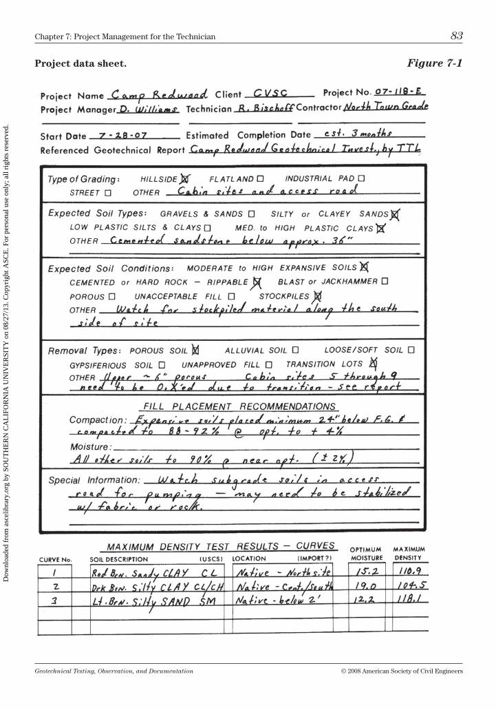
Geotechnical Testing, Observation, and Documentation © 2008 American Society of civil Engineers
chapter 7: Project management for the technician 83
Project data sheet. Figure 7-1
Dow
nloa
ded
from
asc
elib
rary
.org
by
SOU
TH
ER
N C
AL
IFO
RN
IA U
NIV
ER
SIT
Y o
n 08
/27/
13. C
opyr
ight
ASC
E. F
or p
erso
nal u
se o
nly;
all
righ
ts r
eser
ved.
Geotechnical Testing, Observation, and Documentation © 2008 American Society of civil Engineers
84 chapter 7: Project management for the technician
contractors’ “top 10 reasons”
Why their Fill is okay
10. “i shouldn’t need to spend too much time compacting this fill, ’cause after it’s paved there’s going to be a lot of heavy trucks on this road to compact it.”
9. “Ah hell, you know this material is so good we can get compaction by just dumping it into the trench.”
8. “compaction of this fill will be easy; the barometric pressure is going to be high all week.”
7. “Don’t worry—we dug it all out, and then we compacted it while you were gone.”
6. “it’s supposed to rain tonight—and all those drops falling from way up there pack a real wallop when they hit.”
5. “We shouldn’t have to dig out all that fill down there—it’s all native on top!”
4. “Why are you being so hard on us?—the other technicians never took so many tests!”
3. “Don’t worry, after this clay dries out it’ll be plenty hard.”
2. “oh yeah, i remember pulling out that tree stump—you can trust us—we hauled it off site while you were at lunch.”
1. “this vibra-plate will compact two or three feet, easy!”
observation, communication, testing,
and Documentation
on a daily basis a technician will often perform a number of functions on the grading project. these responsibilities can be divided into four main areas—observation, testing, documentation, and communication—although not always performed in this order.
Observation
being in the right place at the right time—the ability to foresee the contractor’s next move—is a valuable skill for a technician. For instance, if a contractor is placing fill at one end of a project and making a removal at the other end, you must decide where you should spend the most time—or whether to divide your
Dow
nloa
ded
from
asc
elib
rary
.org
by
SOU
TH
ER
N C
AL
IFO
RN
IA U
NIV
ER
SIT
Y o
n 08
/27/
13. C
opyr
ight
ASC
E. F
or p
erso
nal u
se o
nly;
all
righ
ts r
eser
ved.
Geotechnical Testing, Observation, and Documentation © 2008 American Society of civil Engineers
chapter 7: Project management for the technician 85
time equally between the two areas. often the best approach is to spend most of your time observing the fill placement, and only stopping by the removal area when scheduled. reach an agreement with the contractor that you must be requested to observe the bottom—only when the contractor believes the removal is complete—and that no fill will be placed prior to your approval of the bottom.
keep in mind that a contractor is usually more willing to add a little more effort during fill placement, rather than to remove and rework an already placed fill. therefore, if during fill placement you notice an area of concern (e.g., poorly mixed soil, nesting of oversized material, or too much moisture), you should alert the foreman of these concerns immediately, and not wait until the point at which fill must be removed to correct the problem. by taking this approach you can save the contractor (and yourself) a lot of time and effort. remember—plan ahead, try to foresee problems, and be proactive.
in observing grading processes ask yourself the following questions:
• Doesthefillhavesufficientmixingandmoistureconditioning?
• Isthereproperbenchingaroundtheouteredgesoffillsthattiesintoexistingengineered fills (of either stable soil or rock)?
• Isthereadequateoverbuildorcompactionoffillslopes?Remindthecontrac-tor that an under-built slope is unacceptable; pasting soil onto a slope face after the slope has been built is not acceptable.
• Haveremovals(e.g.,canyonoralluvialclean-outs,oldfills,andstockpiles)been handled properly?
it is also important to observe other areas of special concern. these include cut slopes (check for out-of-slope bedding, slide planes, seeps, or loose mate-rial), nonengineered fill (watch for buried debris, tanks, or old foundations), and porous, soft soils.
Communication
upon noticing an area of concern, good communication skills become para-mount. the more quickly a technician can bring a problem to the attention of the contractor, the project manager, or supervisor, the sooner a corrective action can be discussed. the importance of tact must not be minimized; try not to put the contractor on the defensive or to “point fingers” when discussing an issue, but at the same time be firm.
While helping to correct a problem, do not direct the contractor on how to per-form the work. Should your method not work, the contractor may then blame you for any wasted time and material! this does not mean that you should not offer alternative suggestions—just make it clear to the contractor that the deci-sion on how to perform the work is entirely up to them. technicians should be concerned with the final product, not usually the process.
Dow
nloa
ded
from
asc
elib
rary
.org
by
SOU
TH
ER
N C
AL
IFO
RN
IA U
NIV
ER
SIT
Y o
n 08
/27/
13. C
opyr
ight
ASC
E. F
or p
erso
nal u
se o
nly;
all
righ
ts r
eser
ved.
Geotechnical Testing, Observation, and Documentation © 2008 American Society of civil Engineers
86 chapter 7: Project management for the technician
Testing
one of your prime responsibilities is to sample materials before placement, and then test during placement. this sampling and testing helps to determine whether the geotechnical recommendations (plans or specifications) are being followed during grading and construction.
Sand cones and nuclear gauges are often used to test the density and moisture content during fill placement. Safety while testing is important. Always coor-dinate your testing with the foreman and/or the equipment operators—nearby equipment should be shut down and your presence should be made obvious.
Tip: When possible, schedule your test taking for a time when equipment is not operating; before they start up, while the operators are breaking for lunch, and after they shut down for the day are all good times. When timed right, contractors may be able to avoid disrupting grading opera-tions for your testing.
if you must take a density test where scrapers, dozers, or other heavy equip-ment are working nearby, the following tips are good (and usually mandatory) safety guidelines:
1. Always wear a bright colored safety vest and, if there is overhead work, a hardhat.
2. be sure the foreman and equipment operators are aware that you are taking tests, and that you are fully visible or are safely protected from construction.
3. When taking a density test in an active fill area, park your vehicle in front of the open end of the excavation and place cross laths with a bright surveyor’s ribbon tied to them on top of the spoil pile at each end of the excavation.
4. carefully watch and listen for approaching equipment.
5. Always be careful! technicians have been injured or killed while testing,
Always notify the contractor of a failing density test result as soon as possible. When a density test has failed, record the test location and elevation on your plans and test sheet. if necessary, leave a lath where the failing test was taken to help warn operators not to bury the test hole until the foreman has a chance to observe the fill. With the foreman present it is easier to point out dry, poorly mixed, or loose areas. use your probe to find and emphasize loose areas.
it is important that the technician and the foreman reach an agreement on the limits of an area that is to be reworked. Sometimes more testing will be needed to better define the limits of unacceptable fill, but often it is just a simple matter of recompacting the last lift of material placed. usually, simply returning to retest the area after it has been reworked is adequate. however, if the limits of
Dow
nloa
ded
from
asc
elib
rary
.org
by
SOU
TH
ER
N C
AL
IFO
RN
IA U
NIV
ER
SIT
Y o
n 08
/27/
13. C
opyr
ight
ASC
E. F
or p
erso
nal u
se o
nly;
all
righ
ts r
eser
ved.
Geotechnical Testing, Observation, and Documentation © 2008 American Society of civil Engineers
chapter 7: Project management for the technician 87
the area are hard to define in advance, the technician should stay to observe the contractor’s operation during rework.
in all cases—upon completion of rework—density retests must be taken at approximately the same location and elevation of the initial test failure(s). Proper documentation of the retest is necessary to show that the failed area has been adequately reworked. For example, if the original test failure number was 43, then the retest number should incorporate the original failure number, such as 43r.
Documentation
All of the technician’s observations, conversations, and test data must be docu-mented. technicians must write a separate daily field report (DFr, Fig. 7-2) for each project worked on, daily. the DFr is important documentation—for it is the written record of meetings, discussions, issues of concern, locations of removals and fills, equipment utilized, and any other important developments that transpire on the job during the day.
technicians should have their own personal daily diary in which they record a general overview (and often very specific conversations) of discussions and activities at each project they visit daily. this personal daily diary is kept for the technician’s own reference and is a valuable record. it can include con-tact names, phone numbers, and often crucial backup of conversations at—and related to—each project worked on.
Each test taken throughout the day must be plotted, either on the grading plans or on a hand-drawn plot plan. the location of each sample (maximum density, expansion, r value, etc.) obtained from the site should also be plotted. Density test information should be recorded (numerically, beginning with test #1 on the first day a test was taken, and continuing numerically, not restarting from #1 again each day) on a density test sheet or a density test summary form (see Fig. 7-3).
the compilation of data for the final grading report is continual throughout the length of the project. If testing and other documentation is kept current daily, paperwork can easily be compiled when the project ends, subsequently making the writing of the final report a relatively simple process.
Dow
nloa
ded
from
asc
elib
rary
.org
by
SOU
TH
ER
N C
AL
IFO
RN
IA U
NIV
ER
SIT
Y o
n 08
/27/
13. C
opyr
ight
ASC
E. F
or p
erso
nal u
se o
nly;
all
righ
ts r
eser
ved.
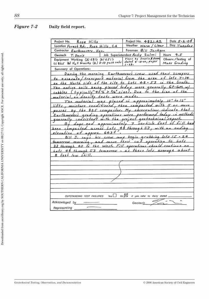
Geotechnical Testing, Observation, and Documentation © 2008 American Society of civil Engineers
88 chapter 7: Project management for the technician
Figure 7-2 Daily field report.
Dow
nloa
ded
from
asc
elib
rary
.org
by
SOU
TH
ER
N C
AL
IFO
RN
IA U
NIV
ER
SIT
Y o
n 08
/27/
13. C
opyr
ight
ASC
E. F
or p
erso
nal u
se o
nly;
all
righ
ts r
eser
ved.
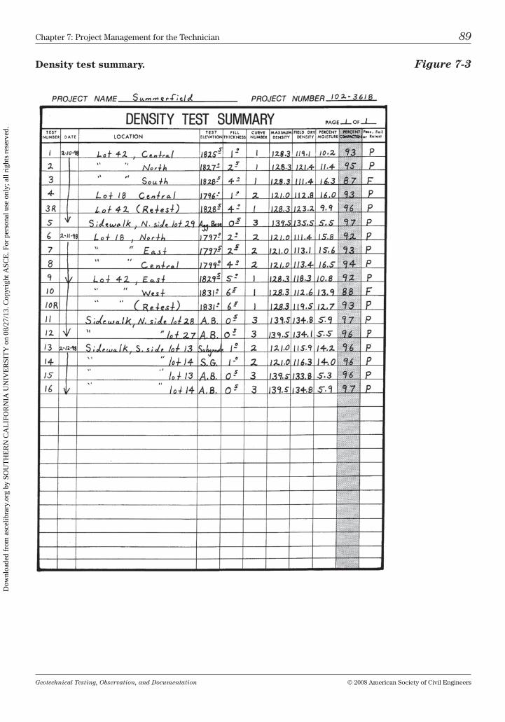
Geotechnical Testing, Observation, and Documentation © 2008 American Society of civil Engineers
chapter 7: Project management for the technician 89
Density test summary. Figure 7-3
Dow
nloa
ded
from
asc
elib
rary
.org
by
SOU
TH
ER
N C
AL
IFO
RN
IA U
NIV
ER
SIT
Y o
n 08
/27/
13. C
opyr
ight
ASC
E. F
or p
erso
nal u
se o
nly;
all
righ
ts r
eser
ved.
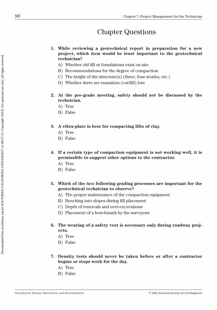
Geotechnical Testing, Observation, and Documentation © 2008 American Society of civil Engineers
90 chapter 7: Project management for the technician
chapter Questions
1. While reviewing a geotechnical report in preparation for a new project, which item would be least important to the geotechnical technician?A) Whether old fill or foundations exist on siteb) recommendations for the degree of compactionc) the height of the structure(s) (three, four stories, etc.)D) Whether there are transition (cut/fill) lots
2. At the pre-grade meeting, safety should not be discussed by the technician.A) trueb) False
3. A vibra-plate is best for compacting lifts of clay.A) trueb) False
4. If a certain type of compaction equipment is not working well, it is permissible to suggest other options to the contractor.A) trueb) False
5. Which of the two following grading processes are important for the geotechnical technician to observe?A) the proper maintenance of the compaction equipmentb) benching into slopes during fill placementc) Depth of removals and over-excavationsD) Placement of a benchmark by the surveyors
6. The wearing of a safety vest is necessary only during roadway proj-ects.A) trueb) False
7. Density tests should never be taken before or after a contractor begins or stops work for the day.A) trueb) False
Dow
nloa
ded
from
asc
elib
rary
.org
by
SOU
TH
ER
N C
AL
IFO
RN
IA U
NIV
ER
SIT
Y o
n 08
/27/
13. C
opyr
ight
ASC
E. F
or p
erso
nal u
se o
nly;
all
righ
ts r
eser
ved.
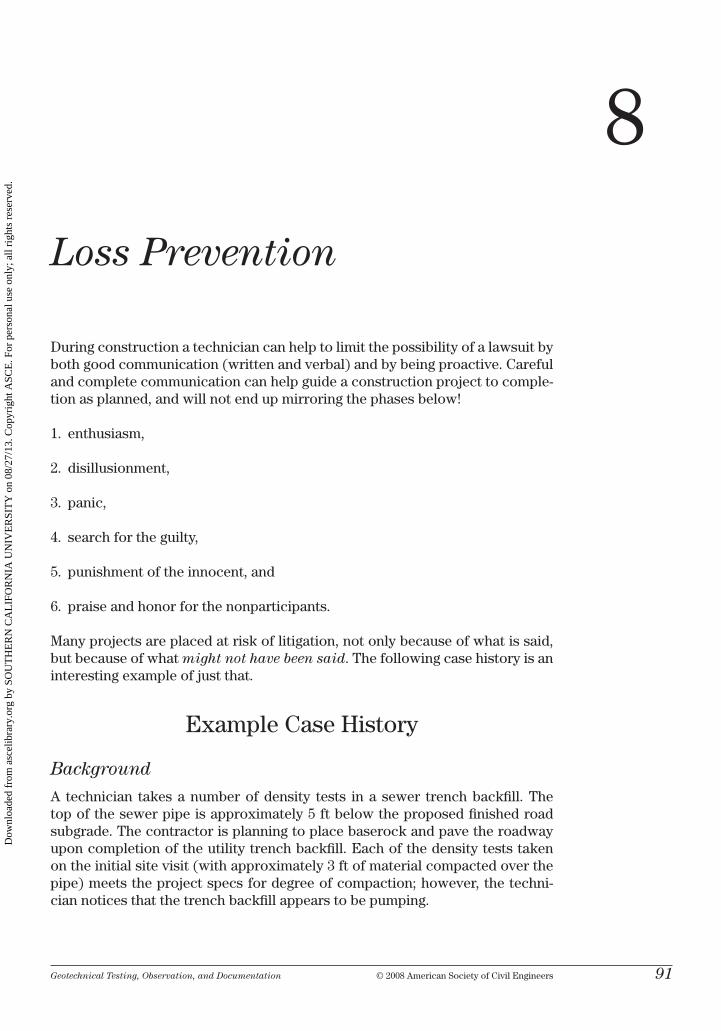
Geotechnical Testing, Observation, and Documentation © 2008 American Society of civil Engineers 91
8
Loss Prevention
During construction a technician can help to limit the possibility of a lawsuit by both good communication (written and verbal) and by being proactive. careful and complete communication can help guide a construction project to comple-tion as planned, and will not end up mirroring the phases below!
1. enthusiasm,
2. disillusionment,
3. panic,
4. search for the guilty,
5. punishment of the innocent, and
6. praise and honor for the nonparticipants.
many projects are placed at risk of litigation, not only because of what is said, but because of what might not have been said. the following case history is an interesting example of just that.
Example case history
Background
A technician takes a number of density tests in a sewer trench backfill. the top of the sewer pipe is approximately 5 ft below the proposed finished road subgrade. the contractor is planning to place baserock and pave the roadway upon completion of the utility trench backfill. Each of the density tests taken on the initial site visit (with approximately 3 ft of material compacted over the pipe) meets the project specs for degree of compaction; however, the techni-cian notices that the trench backfill appears to be pumping.
Dow
nloa
ded
from
asc
elib
rary
.org
by
SOU
TH
ER
N C
AL
IFO
RN
IA U
NIV
ER
SIT
Y o
n 08
/27/
13. C
opyr
ight
ASC
E. F
or p
erso
nal u
se o
nly;
all
righ
ts r
eser
ved.
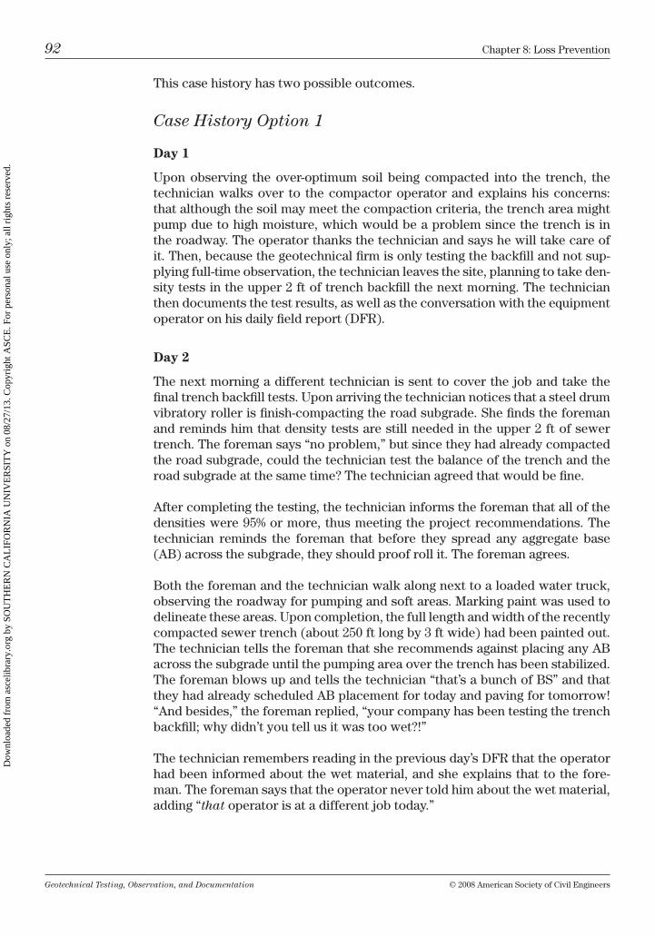
Geotechnical Testing, Observation, and Documentation © 2008 American Society of civil Engineers
92 chapter 8: loss Prevention
this case history has two possible outcomes.
Case History Option 1
Day 1
upon observing the over-optimum soil being compacted into the trench, the technician walks over to the compactor operator and explains his concerns: that although the soil may meet the compaction criteria, the trench area might pump due to high moisture, which would be a problem since the trench is in the roadway. the operator thanks the technician and says he will take care of it. then, because the geotechnical firm is only testing the backfill and not sup-plying full-time observation, the technician leaves the site, planning to take den-sity tests in the upper 2 ft of trench backfill the next morning. the technician then documents the test results, as well as the conversation with the equipment operator on his daily field report (DFr).
Day 2
the next morning a different technician is sent to cover the job and take the final trench backfill tests. upon arriving the technician notices that a steel drum vibratory roller is finish-compacting the road subgrade. She finds the foreman and reminds him that density tests are still needed in the upper 2 ft of sewer trench. the foreman says “no problem,” but since they had already compacted the road subgrade, could the technician test the balance of the trench and the road subgrade at the same time? the technician agreed that would be fine.
After completing the testing, the technician informs the foreman that all of the densities were 95% or more, thus meeting the project recommendations. the technician reminds the foreman that before they spread any aggregate base (Ab) across the subgrade, they should proof roll it. the foreman agrees.
both the foreman and the technician walk along next to a loaded water truck, observing the roadway for pumping and soft areas. marking paint was used to delineate these areas. upon completion, the full length and width of the recently compacted sewer trench (about 250 ft long by 3 ft wide) had been painted out. the technician tells the foreman that she recommends against placing any Ab across the subgrade until the pumping area over the trench has been stabilized. the foreman blows up and tells the technician “that’s a bunch of bS” and that they had already scheduled Ab placement for today and paving for tomorrow! “And besides,” the foreman replied, “your company has been testing the trench backfill; why didn’t you tell us it was too wet?!”
the technician remembers reading in the previous day’s DFr that the operator had been informed about the wet material, and she explains that to the fore-man. the foreman says that the operator never told him about the wet material, adding “that operator is at a different job today.”
Dow
nloa
ded
from
asc
elib
rary
.org
by
SOU
TH
ER
N C
AL
IFO
RN
IA U
NIV
ER
SIT
Y o
n 08
/27/
13. C
opyr
ight
ASC
E. F
or p
erso
nal u
se o
nly;
all
righ
ts r
eser
ved.
Geotechnical Testing, Observation, and Documentation © 2008 American Society of civil Engineers
chapter 8: loss Prevention 93
Outcome
the client (property owner) and the general contractor were adamant in their belief that the first technician should have informed the foreman on the job about the pumping trench soils, not just the operator. After many heated dis-cussions (a few letters and e-mails) exchanged among the client, grading con-tractor, and the geotechnical firm, the geotechnical firm agrees to share the expense of recompacting the upper 2 ft of the trench with Ab.
the geotechnical firm had acquiesced because it felt that it would have been more expensive to go through a lengthy litigation. moreover, since the client was a regular customer, sharing the cost would go a long way toward getting any future business from the client.
Case History Option 2
Day 1
upon observing the over-optimum soil being compacted into the trench, the technician finds the underground foreman and explains his concerns: that although the soil may meet the compaction criteria, the trench area might pump due to high moisture, which would be a problem since the trench is in the road-way. the foreman thanks the technician for the “heads-up.”
the technician then calls the project engineer and explains that, although the trench backfill is being compacted to specs, there is pumping near the finished road subgrade elevation. the technician documents the test results and his con-versations. later that morning the project engineer contacts the project (grad-ing) foreman, as well as the general contractor’s superintendent and discusses the technician’s observations with them both. the engineer documents her con-versations and places a copy in the project office file.
Day 2
the next morning a different technician is sent to cover the job and to take final trench tests. upon arriving, she notices that a steel drum vibratory roller is com-pacting the road subgrade. the technician also sees an approximately 3-ft-wide strip of aggregate baserock running down the length of the road, just slightly south of the centerline.
the technician asks the foreman if the Ab had been used to backfill the sewer trench. the foreman says yes; they used the Ab in the upper 2 ft of the trench because the technician at the job yesterday pointed out the pumping backfill—so they capped the pumping soil with baserock.
After calling the office to get a curve for the aggregate baserock—which had already been used on site for other areas—the technician takes both trench and subgrade tests. Each density test indicates adequate compaction, per the proj-ect specifications. the technician then suggests to the foreman that they proof
Dow
nloa
ded
from
asc
elib
rary
.org
by
SOU
TH
ER
N C
AL
IFO
RN
IA U
NIV
ER
SIT
Y o
n 08
/27/
13. C
opyr
ight
ASC
E. F
or p
erso
nal u
se o
nly;
all
righ
ts r
eser
ved.

Geotechnical Testing, Observation, and Documentation © 2008 American Society of civil Engineers
94 chapter 8: loss Prevention
roll the subgrade prior to placing Ab. both the technician and the foreman walk along next to a loaded water truck to look for any soft or pumping areas. none are observed.
Outcome
the heads-up observation and good communication by the first technician, and the follow-up conversations by the project engineer and the second technician, caused the decision by the foreman to cap the trench with Ab, thus allowing the paving schedule to be met by the contractor. Furthermore, both the contractor and the client came away from the project looking forward to the next time they would work with the geotechnical firm.
Tips: Be Proactive: by visualizing ahead what the contractor’s next operation is to be, the first technician (in option 2) is able to save all parties involved in the roadway construction both time and money. The ability to foresee how a current grading or backfill operation might effect future construction is an important skill to learn and use.
Fully Communicate: it is important to voice your concerns to all the proper “authority” personnel on the project. clearly communicating your observations and concerns to the project manager, foreman, or client can help to influence the outcome of the project in a positive manner.
Proper Word choices for
Daily Field report Writing
many litigations are filed annually against developers, construction companies, and engineering firms to recoup costs for unplanned expenses during construc-tion or for structural damage attributed to poor construction. often structural damage or hillside failures are caused by the grading contractor doing a bad job not following the geotechnical recommendations or maybe by the devel-opers being too cheap to hire believing they did not need the services of a geotechnical firm for full-time inspection and fill control observation and testing. And, although the geotechnical firm was only asked to monitor a por-tion of the project (and was not directly involved in the area of failure), they may nevertheless be found liable for damages. the decision to find a geotech-nical firm liable is often based on documentation (or lack of) contained in the technician’s or engineer’s DFr. For reference, a sample DFr with inappropriate words crossed out is included as Fig. 8-1.
During the course of a year, technicians may write hundreds of DFrs—which represent hundreds of opportunities to open the door to litigation. many words that we use in everyday life when we are off the job, unfortunately, should not be used in the geotechnical world. therefore, it is important that observations are documented as clearly and accurately as possible, with care being taken with how we communicate these observations. certain words and phrases may
Dow
nloa
ded
from
asc
elib
rary
.org
by
SOU
TH
ER
N C
AL
IFO
RN
IA U
NIV
ER
SIT
Y o
n 08
/27/
13. C
opyr
ight
ASC
E. F
or p
erso
nal u
se o
nly;
all
righ
ts r
eser
ved.
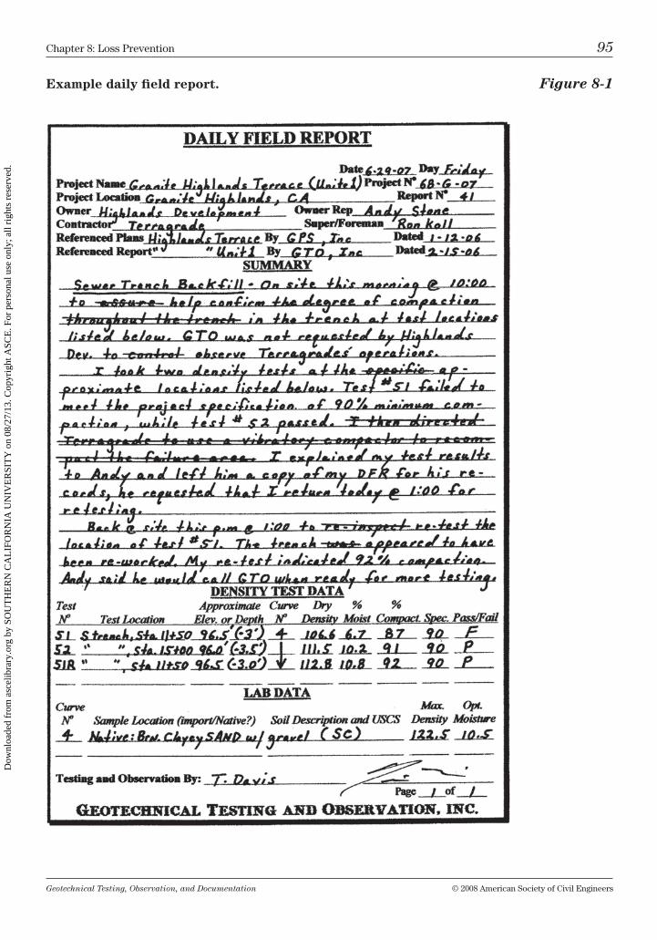
Geotechnical Testing, Observation, and Documentation © 2008 American Society of civil Engineers
chapter 8: loss Prevention 95
Example daily field report. Figure 8-1
Dow
nloa
ded
from
asc
elib
rary
.org
by
SOU
TH
ER
N C
AL
IFO
RN
IA U
NIV
ER
SIT
Y o
n 08
/27/
13. C
opyr
ight
ASC
E. F
or p
erso
nal u
se o
nly;
all
righ
ts r
eser
ved.
Geotechnical Testing, Observation, and Documentation © 2008 American Society of civil Engineers
96 chapter 8: loss Prevention
be interpreted differently than they were intended. As presented at many loss prevention seminars* and suggested by insurance carriers for the engineer-ing industry,† commonly used “red flag” words to be avoided include the following:
directed approve control
supervised assure inspect
told certify oversaw
required is ok
the following are preferred words to be used in lieu of red flag words:
recommend in general accordance document
proposed appears to conform observed
suggested generally consistent tested
Extreme words, words of multiple meaning, and words of promise should be avoided. A DFr that is concise and not overly lengthy is easier to understand—and to defend if necessary. With practice, and a cautious eye, writing a good DFr will become second nature.
Tips: Never admit guilt; if confronted by an irate contractor or upset owners’ representative, remember that there are often many explana-tions for a given situation, and taking time to think about the issues and discuss them with the project engineer is wise.
Fully document; record daily project activities, discussions, and issues—including how and if the issues were resolved. your notes should be a nonemotional, nonpersonal, accurate record.
* A good reference for proper nomenclature is “Watch your Engineering Jargon,” published as part of collected seminars and papers by the ASFE (formerly the Associated Soil and Founda-tion Engineers) and the california Geotechnical Engineers Association (cGEA) in mP-21 (pages 67–71) of Geotechnical Technicians’ Reference Manual.
† the DPic companies has a well-written “communications” chapter (pages 12–26) included in their Lessons in Professional Liability handbook, 2002 edition, which describes how the improper use of words can instigate a claim.
Dow
nloa
ded
from
asc
elib
rary
.org
by
SOU
TH
ER
N C
AL
IFO
RN
IA U
NIV
ER
SIT
Y o
n 08
/27/
13. C
opyr
ight
ASC
E. F
or p
erso
nal u
se o
nly;
all
righ
ts r
eser
ved.

Geotechnical Testing, Observation, and Documentation © 2008 American Society of civil Engineers
chapter 8: loss Prevention 97
chapter Questions
1. If a density test has failed, it is important to direct the contractor on what type of equipment to use to assure a passing test.A) trueb) False
2. Which two descriptions should be avoided when writing a daily field report?A) Fill controlb) observedc) inspectedD) Generally acceptable
3. It is the technicians’ responsibility to communicate with the equip-ment operators and the laborers on a construction project.A) trueb) False
4. It is the technicians’ responsibility to communicate with the fore-man, superintendent, project manager, and developer on a construc-tion project.A) trueb) False
5. Even though a density test has failed in a roadway subgrade, as long as the subgrade has been proof rolled, there is no need for a retest of the failure.A) trueb) False
Dow
nloa
ded
from
asc
elib
rary
.org
by
SOU
TH
ER
N C
AL
IFO
RN
IA U
NIV
ER
SIT
Y o
n 08
/27/
13. C
opyr
ight
ASC
E. F
or p
erso
nal u
se o
nly;
all
righ
ts r
eser
ved.

This page intentionally left blank
Dow
nloa
ded
from
asc
elib
rary
.org
by
SOU
TH
ER
N C
AL
IFO
RN
IA U
NIV
ER
SIT
Y o
n 08
/27/
13. C
opyr
ight
ASC
E. F
or p
erso
nal u
se o
nly;
all
righ
ts r
eser
ved.
Geotechnical Testing, Observation, and Documentation © 2008 American Society of civil Engineers 99
Safety in the Field
it is crucial that you approach all field work with safety in mind. Safety on the job should never be compromised because of laziness, time, or budget con-straints. Follow all federal and/or state occupational Safety and health Admin-istration (oShA) guidelines, as well as local authority and any project-specific safety guidelines. if unsure of a safety issue, consult your company’s safety offi-cer or the governing authority.
trench Safety
never go into a trench that appears unsafe or has not been properly shored or sloped back. Always be sure there is a ladder, stairway, or ramp for easy access into and out of the trenches deeper than 4-ft. check that the ladder is on firm, level ground and is properly braced or secured before putting your weight on it.
make it a habit to look at the top edges of the trench for any loose rocks, tools, or debris that could fall in while you are working below. look around to see if any heavy equipment is working nearby; if so, alert the operator to stop work-ing in your vicinity so that no material can be inadvertently pushed into the trench where you are working. be familiar with oShA 29 cFr Part 1926, Sub-part P—Excavations.
Trench Safety Guidelines
• All excavations (even less than 5-ft deep) must be examined by a competent person [refer to oShA Subpart P, 1926.652(a)(1)(ii), and Appendix F to Sub-part P]. Even trenches less than 5 ft in depth can be unstable and dangerous. there is no statement by oShA that says that only trenches deeper than 5 ft need to be sloped or shored!
• Ensure safe access and egress. trench excavations deeper than 4 ft require a stairway, ladder, or ramp spaced at no greater interval than 25 ft [refer to oShA Subpart P, 1926.651(c)(2)].
• Avoid hazardous atmospheres. Adequate precautions must be taken to pre-vent employee exposure to atmospheres containing less than 19.5% oxygen or other hazardous atmospheres [refer to oShA Subpart P, 1926.651(g)].
9
Dow
nloa
ded
from
asc
elib
rary
.org
by
SOU
TH
ER
N C
AL
IFO
RN
IA U
NIV
ER
SIT
Y o
n 08
/27/
13. C
opyr
ight
ASC
E. F
or p
erso
nal u
se o
nly;
all
righ
ts r
eser
ved.
Geotechnical Testing, Observation, and Documentation © 2008 American Society of civil Engineers
100 chapter 9: Safety in the Field
• Alwayswear a hardhat in excavations.
• Watch for any overhead hazards, such as loose material or equipment close to the top of the excavation.
• Be familiar with sloping and benching requirements, including the classifi-cation of soil or rock type, as listed in Appendixes A and b of oShA Subpart P. Do not enter a trench that has not been properly shored or braced.
• Under no circumstances should you go into a trench excavation with which you have safety concerns.
Example
Figure 9-1 shows an unsafe trench excavation. Due to the low cohesive nature of this sandy gravelly formation, the contractor elected to excavate a large square excavation to allow access to form caissons for a microwave tower founda-tion. the contractor then began compacting the bottom of the 6-ft-deep excava-tion as a pad for the caisson bases. the foreman called a geotechnical firm and requested that it send out a technician to take some density tests.
After viewing the unshored, unsloped excavation, the technician refused to go into the hole to take tests. the foreman threatened to kick the technician’s firm off the job and to hire another company that was not afraid to go into the exca-vation and take tests. the technician called his office and informed the project engineer of his concerns. the engineer contacted oShA. oShA “red tagged” the job until the contractor safely shored or sloped the excavation. the walls of the excavation were subsequently shored by the contractor. the backfill testing was then completed safely.
the technician made the right decision by not being forced into an unsafe situ-ation and was ultimately supported by his company and oShA. the contractor was not only required to safely shore the excavation but was fined as well.
Grading Project Safety
When driving onto a grading project site, stop and take time to observe the flow of equipment traffic. Sometimes haul roads have only one way or even reverse traffic directions. keep a safe distance behind heavy equipment since smaller vehicles often cannot be seen when following large trucks, scrapers, and other heavy equipment. While walking across a site or taking tests where dozers, scrapers, or other heavy pieces of equipment are working, always wear a brightly colored safety vest. never climb onto a piece of heavy equipment to communicate with the operator: have the operator stop the equipment and, if necessary, get off prior to communicating.
never leave your testing equipment (sand cone, nuclear gauge, etc.) unattended on a job site. the nuclear gauge should always be properly locked and placed securely into your truck bed when not in use.
Dow
nloa
ded
from
asc
elib
rary
.org
by
SOU
TH
ER
N C
AL
IFO
RN
IA U
NIV
ER
SIT
Y o
n 08
/27/
13. C
opyr
ight
ASC
E. F
or p
erso
nal u
se o
nly;
all
righ
ts r
eser
ved.

Geotechnical Testing, Observation, and Documentation © 2008 American Society of civil Engineers
chapter 9: Safety in the Field 101
Unsafe trench excavation. Figure 9-1
Unsafe driving conditions. Figure 9-2
Dow
nloa
ded
from
asc
elib
rary
.org
by
SOU
TH
ER
N C
AL
IFO
RN
IA U
NIV
ER
SIT
Y o
n 08
/27/
13. C
opyr
ight
ASC
E. F
or p
erso
nal u
se o
nly;
all
righ
ts r
eser
ved.
Geotechnical Testing, Observation, and Documentation © 2008 American Society of civil Engineers
102 chapter 9: Safety in the Field
While taking a density test, make sure you are visible to the equipment opera-tors at all times. to help ensure visibility during testing, a lath with a brightly colored ribbon can be placed on top of the spoil pile created from your test hole. many engineering companies now require flashing warning lights or red flags to be placed on their vehicles while on a grading project. After you have completed taking your test(s), move out of the construction zone before calcu-lating and logging your tests.
Stay away from unsafe cut slopes, such as those created by keyway excavations or in road cuts. Figure 9-2 shows what can happen when the driver of a water truck chose to drive the haul road before the dozer had completed leveling it. luckily, when the truck slid off the road, the driver was not hurt. he was doubly lucky since the day before he had his 10-year-old son riding with him!
Always inform the job foreman of any unsafe situations and remind him or her of any relevant oShA guidelines or project recommendations (such as laying back slopes to a safer angle). record all safety-related conversations in your daily report.
if at any time you feel that an unsafe condition or situation exists on a job site, immediately withdraw from the area and contact the job superintendent, your supervisor, or other appropriate personnel. The best defense against an on-the-job injury is to follow all safety guidelines. Use common sense and good judgment in all safety-related issues.
Dow
nloa
ded
from
asc
elib
rary
.org
by
SOU
TH
ER
N C
AL
IFO
RN
IA U
NIV
ER
SIT
Y o
n 08
/27/
13. C
opyr
ight
ASC
E. F
or p
erso
nal u
se o
nly;
all
righ
ts r
eser
ved.
Geotechnical Testing, Observation, and Documentation © 2008 American Society of civil Engineers 103
Putting It All Together An Example Project
Scenario
A geotechnical firm is asked by a local developer to perform a geotechnical investigation on a nearby 14-acre plot of land. the developer says that he tenta-tively wants to build an approximately 280-unit apartment complex and associ-ated roadways and parking areas. the site is currently vacant with no existing structures and is fronted along the south by a two-lane paved road.
information obtained from the site investigation will be used by the project engineer to develop recommendations for earthwork and specifications for foundations, paved parking areas and driveways, concrete flatwork, and utility placement. During exploration, lab work, grading and construction, technicians from the firm will be involved.
At project completion the technician will put together all the project field docu-mentation in a form that the project engineer can easily use in preparation of the final report. in this scenario each phase will be discussed: site investigation, pre-job meeting and project preparation, construction—observation and test-ing, communication, and the compilation of documentation for the final geo-technical report. An example geotechnical report is presented at the end of this chapter.
Site investigation
Prior to beginning field work for a site investigation, a project engineer has much preparation to do: determining the scope of the work, estimating a budget for engineering services, getting a signed contract with the developer, applying for permits, hiring drilling rig (or backhoe) crew, determining the type of explo-ration (e.g., boreholes, trenches, and rippability study), and performing many other coordination tasks.
10
Dow
nloa
ded
from
asc
elib
rary
.org
by
SOU
TH
ER
N C
AL
IFO
RN
IA U
NIV
ER
SIT
Y o
n 08
/27/
13. C
opyr
ight
ASC
E. F
or p
erso
nal u
se o
nly;
all
righ
ts r
eser
ved.
Geotechnical Testing, Observation, and Documentation © 2008 American Society of civil Engineers
104 chapter 10: Putting it All together: An Example Project
Initial Site Visit
A technician may be asked to do a site reconnaissance during the planning pro-cess. Some of the site information necessary to gather for the project engineer will include the following:
• Locating all existing underground utilities within the area of investiga-tion. this is the most important item of concern: before doing any under-ground work a utility-locating organization (such as underground Service Alert or other regional agency) must be contacted.
• Ascertaining site accessibility. is the site fenced or does it have a locked gate? Are some areas impassible without four-wheel-drive or track-mounted equipment because of soft or steep terrain?
• Determiningwhetherthereareoverheadutilitiesorother potential haz-ards to avoid during site exploration.
• Creating a site sketch that includes information such as approximate locations of any existing structures, septic tanks, stockpiles, large trees (or planted areas—orchards, farmed fields, etc.), existing dirt or paved roads, and any other important natural or artificial features.
once a date for the site exploration has been set, and the locations of bore-holes and trenches have been tentatively laid out, it is wise to prelocate them with numbered survey stakes (such as b-1, t-2, etc.) prior to the time the drill rig or backhoe arrives on site, thus saving valuable equipment and operator time. boreholes and trenches should be numbered sequentially, in the order explored. Determine the best access to each staked location and discuss the type of testing necessary and the terrain to be traversed with the drill-rig and/or backhoe operators.
Borehole and Trench Logging
have all supplies necessary for sampling and logging ready the day before the investigation. basic and useful supplies necessary for field investigations include:
• largeandsmallplasticsamplebags;
• sampletagsandlabels;
• boringandtrenchlogs;
• samplingequipment:splitbarrelsampler(SPTandringsampler),plasticringsample jars, tube sampler and tubes (Shelby, Pitcher, etc.);
• samplingboxwithavarietyofsupplies,includingelectricaltape,ducttape,indelible markers, sample cutting blades or piano wire, water squirt bottle,
Dow
nloa
ded
from
asc
elib
rary
.org
by
SOU
TH
ER
N C
AL
IFO
RN
IA U
NIV
ER
SIT
Y o
n 08
/27/
13. C
opyr
ight
ASC
E. F
or p
erso
nal u
se o
nly;
all
righ
ts r
eser
ved.
Geotechnical Testing, Observation, and Documentation © 2008 American Society of civil Engineers
chapter 10: Putting it All together: An Example Project 105
munsell soil color chart, large pipe wrenches, flat-head screwdrivers, large and small wire brushes, and any other helpful tools; and
• miscellaneoussuppliessuchasageologisthammer,aflat-headshovel,amag-nifying lens, a plywood board for cutting apart samples, boxes with foam/padded inserts for shipping ring/tube samples, rags, paper towels, gloves, and a chain vise (which can be very helpful for breaking sample barrels loose).
Figure 2 in the Example Geotechnical Report (at the end of this chapter) is a topographic site plan with borehole and trench locations shown. be sure to plot each borehole or trench location on a similar plan. After the sampling is done, when samples are moved to the lab, they should be placed in well-padded containers and transported carefully in the “upward” position. this will help to minimize any disturbance during transport. A description of exploration tech-niques and sampling methods is described in chapter 2 of this text.
Laboratory Testing
When the exploratory samples are brought to the lab, the project engineer will determine which samples to test and what tests are to be run on each sample. test requests for the project will be submitted to the lab manager, who will then prepare a testing program. Each test will be performed by a technician expe-rienced in performing the test procedure according to the necessary standard (AStm, AAShto, etc.). the test results will then be reviewed by the lab man-ager and the project engineer.
upon completion of both the field exploration and the laboratory testing the engineer will use the information to put together the geotechnical report. An example geotechnical report is included at the end of this chapter.
office Pre-job meeting
once a starting date has been scheduled for a project, an office meeting should be held. both the technician who will be on the job and the engineer who will be the project manager should attend the meeting. During this meeting the techni-cian should learn as much information as possible about the project, including the following:
• The starting date and estimated time length of the job should be agreedupon.
• Thereshouldbeafulldiscussionofthegeotechnicalreport;including,
• thetypeofsoilsencountered;
• anyspecialtreatmentofthesesoilsduringgradingsuchasmoistureanddensity criteria;
Dow
nloa
ded
from
asc
elib
rary
.org
by
SOU
TH
ER
N C
AL
IFO
RN
IA U
NIV
ER
SIT
Y o
n 08
/27/
13. C
opyr
ight
ASC
E. F
or p
erso
nal u
se o
nly;
all
righ
ts r
eser
ved.
Geotechnical Testing, Observation, and Documentation © 2008 American Society of civil Engineers
106 chapter 10: Putting it All together: An Example Project
• removalsofoldstructures,trees,stockpiles,poroussoil,expansivesoil,or other unacceptable material;
• specialgradingsuchasbuttressfills,keyways,canyonclean-outs,sub-drain placements, cut/fill pad treatment, over-excavations, etc.; and
• constructionrecommendationsforstructuresandfoundations;includ-ing, footings, retaining walls, concrete culverts, slabs, and pavements.
• Contractor and client relations should be established. Find out who yourcontacts are; decide if you are required to leave a copy of your test results or DFr on site.
• Thedetailedbudgetshouldbediscussed.Willtheprojectbefullorpart-time?how many hours per day are required? What type of lab and field testing will be necessary?
this meeting with the project engineer is the best way to plan and get informa-tion about the project, don’t hesitate to ask questions.
Project Preparation
it is important to prepare in advance for paperwork (both field and office), take necessary samples, and generally become familiar with the project site and plans. the following offers a basic checklist for preparation:
1. Create a field file. this should include
• theprojectdatasheet(filledoutsimilartotheoneshowninChapter7);
• dailyfieldreports;
• densitytestresultsinnumericalorder;alwaysbegintestsequencenum-bering the first day of testing and continue numerically until the job is complete;
• lab data, including Proctors (with a complete soil description) and allother project lab data; and
• allcorrespondencefromyouroffice,thecontractor,anddeveloper,andallother pertinent project information.
2. Review the plans. highlight cuts and fills; become familiar with the loca-tions of proposed structures, utility locations, areas of special soils (per the geotechnical report).
3. Drive or walk the job site. this is the best way to become familiar with the actual site conditions.
Dow
nloa
ded
from
asc
elib
rary
.org
by
SOU
TH
ER
N C
AL
IFO
RN
IA U
NIV
ER
SIT
Y o
n 08
/27/
13. C
opyr
ight
ASC
E. F
or p
erso
nal u
se o
nly;
all
righ
ts r
eser
ved.
Geotechnical Testing, Observation, and Documentation © 2008 American Society of civil Engineers
chapter 10: Putting it All together: An Example Project 107
4. When possible pick up Proctor samples in advance from the site (native) soils and any samples of import material (if known).
5. Set up a pre-con (pre-grade) meeting.
on-site Pre-grade meeting
this meeting is crucial and should always be held prior to any grading work by the contractor. At a minimum, attendees should include the contractor’s rep-resentatives (superintendent and foreman), the client’s representative(s), the technician, and the project engineer. topics of discussion should include the following:
• Exchange contact information. Aside from business cards, a sign-in sheet for the meeting (with everyone getting a copy) is a great way to do this.
• Discuss the geotechnical report. it is critical that the contractor under-stands the recommendations in the report. Never assume that the contrac-tor has read and understands the geotechnical report. take time to discuss moisture and compaction specifications and all other project-specific grad-ing recommendations.
• Ask for a schedule of work. include in the schedule what hours and days the contractor plans to work.
• Set the ground rules. For instance, make it clear that no fill shall be placed in any area until you (or a representative from your firm) has observed and approved the bottom, and clarify that any area with a failing density test shall have no more fill placed until the area has been reworked and has been retested (with a passing test).
• Discuss safety. remind the contractor that all heavy equipment must be stopped nearby where a technician is taking density tests (or other sampling) on the project. Discuss trench safety with the contractor; reaffirm that you will not go into an unsafe trench; trenches must be shored (or sloped) and have ladders, per oShA standards.
• Review the plans. Point out any areas that will need special grading, such as transition lots, areas requiring over-excavation, fill slopes that will need a keyway and benching, and the like.
construction: testing and observation
once the job has begun it is necessary that technicians plan their time on site carefully. often contractors do not tell the technician (unintentionally or inten-tionally!) where they plan to work next. it is the technician’s responsibility to ask the foreman what the plan is—on a daily basis (or more often as needed).
Dow
nloa
ded
from
asc
elib
rary
.org
by
SOU
TH
ER
N C
AL
IFO
RN
IA U
NIV
ER
SIT
Y o
n 08
/27/
13. C
opyr
ight
ASC
E. F
or p
erso
nal u
se o
nly;
all
righ
ts r
eser
ved.
Geotechnical Testing, Observation, and Documentation © 2008 American Society of civil Engineers
108 chapter 10: Putting it All together: An Example Project
Quite often the contractor will be working more than one area at a time or be moving among various areas. technicians should drive (or walk) the job site as often as necessary during the day so as not to miss grading or other operations.
Tracking Grading and Backfill Operations
throughout the day, as grading and backfill operations take place, technicians should document the work on their DFrs, as well as mark the progress on a set of project plans. colored highlighting markers make an excellent tool for marking up plans. it often happens that technicians switch projects, and when accurate and current records of the operations have been kept the transition is smooth; however, if the field file or plans are not up to date when handed off, the transition can become a nightmare.
the following are a few tips on keeping field records up to date and easy to understand:
• Complete your DFR at the end of each day and always leave one copy in the field file.
• Highlight bottom removals, clean-outs, and grubbed areas on the plans; include a date with your initials next to the area and note bottom and other important elevations.
• Track utility trench backfill by using different colored highlighters for each utility (e.g., blue for water, yellow for gas, and green for sewer). number your test locations on the plans next to the trench, and then when the trench testing has been completed (with all tests passing) finish highlighting the trench.
• Locate all density tests on the plans. number them numerically begin-ning with the first test taken on the project, and then continue numbering consecutively until the project is complete. (Do not start over with number 1 each day.)
• Note test failures on the test sheet, the plans, and the DFr. All test failures must have a retest (or written documentation explaining why they were not retested).
• Retests should be numbered the same as the original test failure with the addition of an “r” (i.e., if test number 231 failed, then the retest will be test number 231r—additional retests could be 231r1, 231r2, etc.). Retests must be made at the same location and elevation (depth) as the original test failure.
• Keep a current list of Proctors for the project. these Proctors should be numbered consecutively and each one should have a complete soil descrip-tion along with the maximum density and optimum moisture values.
Dow
nloa
ded
from
asc
elib
rary
.org
by
SOU
TH
ER
N C
AL
IFO
RN
IA U
NIV
ER
SIT
Y o
n 08
/27/
13. C
opyr
ight
ASC
E. F
or p
erso
nal u
se o
nly;
all
righ
ts r
eser
ved.

Geotechnical Testing, Observation, and Documentation © 2008 American Society of civil Engineers
chapter 10: Putting it All together: An Example Project 109
Remember: When choosing a Proctor, always compare the soil in the field with the soil description of the Proctor. never choose a Proctor just because the maximum density “looks right” or will make the test pass.
Be Proactive
As they say, “the best defense is a good offense,” and on complicated grading projects an experienced technician should try to foresee the contractor’s next move, and if that next move appears problematic, it is time to speak up. bring your concerns to the contractor’s foreman. Do not direct the contractor, but a well-thought-out suggestion can be very helpful. if you do not feel that the con-tractor is heeding your advice, and you still have concerns about the operation, then speak with your project engineer. Document all of your conversations.
try to develop a good working relationship with the contractor, not an adversar-ial one. most contractors are receptive to good suggestions from the technician, but remember, there is often more than one way to perform the construction operation—it is ultimately up to the contractor to decide how best to perform the work, and for the technician to document the work, not to direct the work.
communication—With the contractor
and your office
During the course of the project good communication among the contractor, the project engineer, and the technician is paramount. one excellent way to close the loop on communication is to speak with both the construction foreman or superintendent and your project engineer each day, or more often as needed. communication is often by e-mail; this is a good way to keep your office and the contractor’s office aware of the daily progress on the job, by providing updated information to them.
take care when communicating—especially in writing (whether hand-written or by e-mail)—to keep your discussion brief and on point. When discussing unacceptable work, failing density tests, or other areas of concern, take care not to embellish with “he said–she said” or by implying incompetence or other potentially inflammatory statements. remember that once something is put into writing, it is hard to take back—be professional.
Documentation—the Paper trail
it is important to record everything that was tested and observed by the techni-cian during the course of the project. Anything that is not documented in writ-ten (or photographic) form will probably be forgotten. take the time on a daily basis to complete your paperwork while it is still fresh in your memory. Along with writing DFrs, taking photos of the work is also an excellent way to docu-
Dow
nloa
ded
from
asc
elib
rary
.org
by
SOU
TH
ER
N C
AL
IFO
RN
IA U
NIV
ER
SIT
Y o
n 08
/27/
13. C
opyr
ight
ASC
E. F
or p
erso
nal u
se o
nly;
all
righ
ts r
eser
ved.

Geotechnical Testing, Observation, and Documentation © 2008 American Society of civil Engineers
110 chapter 10: Putting it All together: An Example Project
ment the work performed. Place copies of the photos in your field file and save to disk or hard drive whenever possible.
take time at the end of the project to confirm that all test locations are plotted on your plans and that all failed density tests have been retested. organize all of the test data (field and lab) and DFrs so that the project manager can easily use the information when writing the “Final observation and testing report.”
Dow
nloa
ded
from
asc
elib
rary
.org
by
SOU
TH
ER
N C
AL
IFO
RN
IA U
NIV
ER
SIT
Y o
n 08
/27/
13. C
opyr
ight
ASC
E. F
or p
erso
nal u
se o
nly;
all
righ
ts r
eser
ved.
Geotechnical Testing, Observation, and Documentation © 2008 American Society of civil Engineers
chapter 10: Putting it All together: An Example Project 111
Example Geotechnical Report
Project No. 2008.42.G
GEOTECHNICAL REPORTFOR PROPOSED 280 UNIT APARTMENT COMPLEX
LOCATED IN WOODVILLE HEIGHTS,PARCEL 36C,
WOODVILLE, CALIFORNIA
Prepared for:mr. ron Adams
Woodville realtors Association3500 n. main Street
Woodville, california 98392
Dear mr. Adams,the Geotechnical testing and observation Group is pleased to present the results of this geotechnical site evaluation for the proposed 280 unit apartment complex to be built on Parcel 36c in the city of Woodville, california. our report presents a geotechnical evalua-tion of the site along with conclusions and recommendations for the design and construc-tion of the proposed project.GtoG appreciates the opportunity to be of service to you during this phase of your project.
Sincerely,GtoG
John l. rosen, P.E. Jeffery k. Fitzpatrick, G.E.Project Engineer Senior Geotechnical Engineer
Dow
nloa
ded
from
asc
elib
rary
.org
by
SOU
TH
ER
N C
AL
IFO
RN
IA U
NIV
ER
SIT
Y o
n 08
/27/
13. C
opyr
ight
ASC
E. F
or p
erso
nal u
se o
nly;
all
righ
ts r
eser
ved.
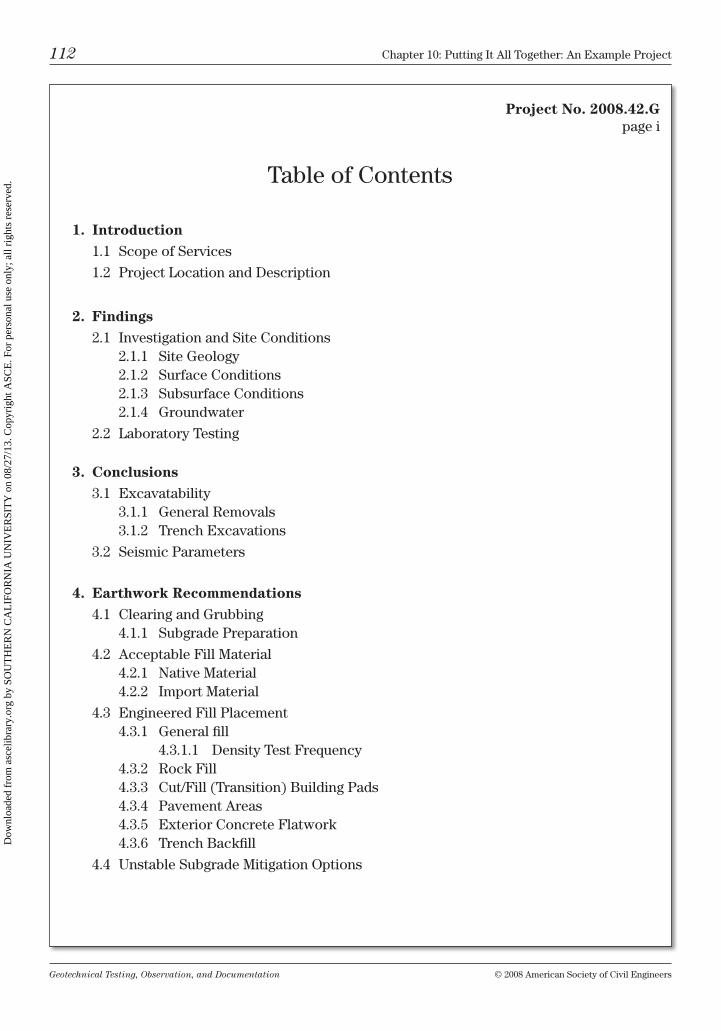
Geotechnical Testing, Observation, and Documentation © 2008 American Society of civil Engineers
112 chapter 10: Putting it All together: An Example Project
table of contents
1. Introduction
1.1 Scope of Services
1.2 Project location and Description
2. Findings
2.1 investigation and Site conditions2.1.1 Site Geology2.1.2 Surface conditions2.1.3 Subsurface conditions2.1.4 Groundwater
2.2 laboratory testing
3. Conclusions
3.1 Excavatability3.1.1 General removals3.1.2 trench Excavations
3.2 Seismic Parameters
4. Earthwork Recommendations
4.1 clearing and Grubbing4.1.1 Subgrade Preparation
4.2 Acceptable Fill material4.2.1 native material4.2.2 import material
4.3 Engineered Fill Placement4.3.1 General fill
4.3.1.1 Density test Frequency4.3.2 rock Fill4.3.3 cut/Fill (transition) building Pads4.3.4 Pavement Areas4.3.5 Exterior concrete Flatwork4.3.6 trench backfill
4.4 unstable Subgrade mitigation options
Project No. 2008.42.Gpage i
Dow
nloa
ded
from
asc
elib
rary
.org
by
SOU
TH
ER
N C
AL
IFO
RN
IA U
NIV
ER
SIT
Y o
n 08
/27/
13. C
opyr
ight
ASC
E. F
or p
erso
nal u
se o
nly;
all
righ
ts r
eser
ved.
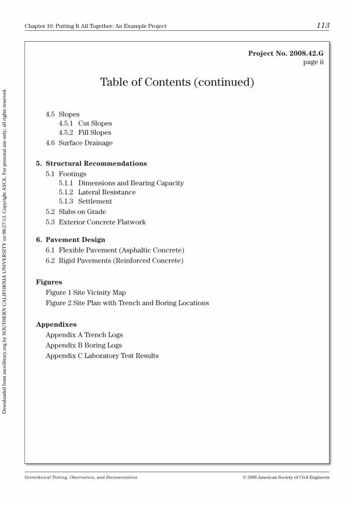
Geotechnical Testing, Observation, and Documentation © 2008 American Society of civil Engineers
chapter 10: Putting it All together: An Example Project 113
4.5 Slopes4.5.1 cut Slopes4.5.2 Fill Slopes
4.6 Surface Drainage
5. Structural Recommendations
5.1 Footings5.1.1 Dimensions and bearing capacity5.1.2 lateral resistance5.1.3 Settlement
5.2 Slabs on Grade
5.3 Exterior concrete Flatwork
6. Pavement Design
6.1 Flexible Pavement (Asphaltic concrete)
6.2 rigid Pavements (reinforced concrete)
Figures
Figure 1 Site vicinity map
Figure 2 Site Plan with trench and boring locations
Appendixes
Appendix A trench logs
Appendix b boring logs
Appendix c laboratory test results
table of contents (continued)
Project No. 2008.42.Gpage ii
Dow
nloa
ded
from
asc
elib
rary
.org
by
SOU
TH
ER
N C
AL
IFO
RN
IA U
NIV
ER
SIT
Y o
n 08
/27/
13. C
opyr
ight
ASC
E. F
or p
erso
nal u
se o
nly;
all
righ
ts r
eser
ved.
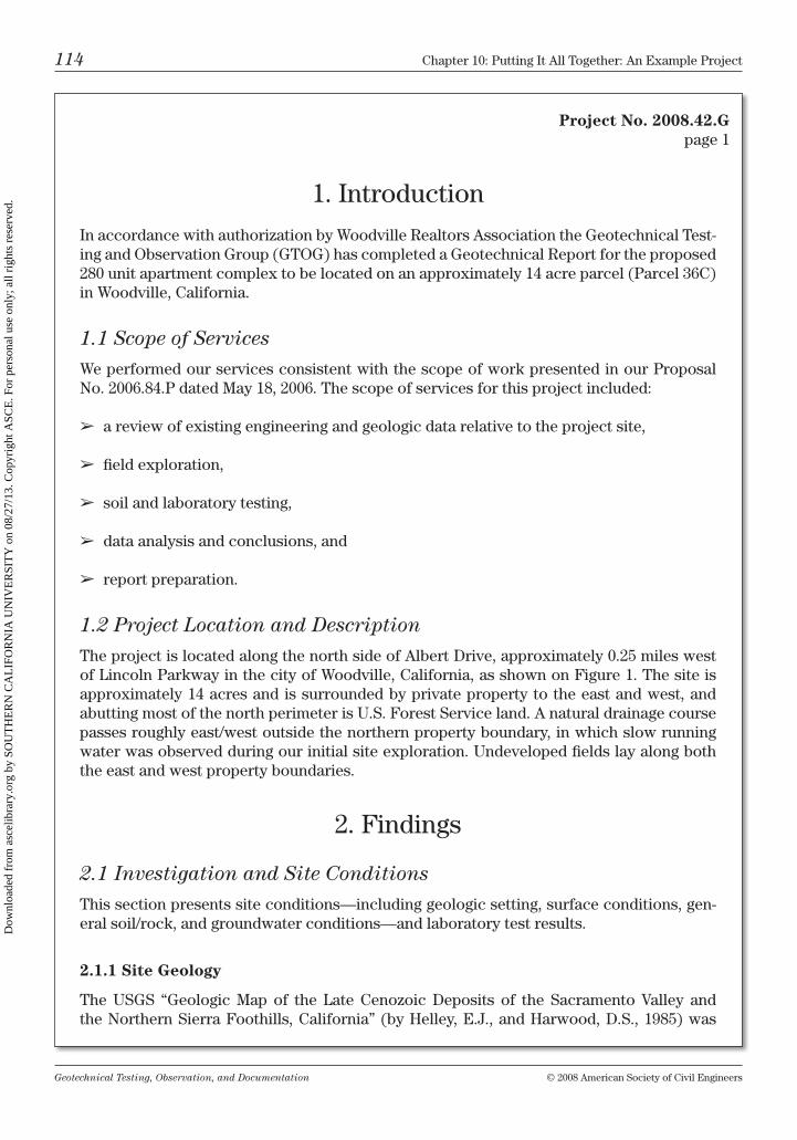
Geotechnical Testing, Observation, and Documentation © 2008 American Society of civil Engineers
114 chapter 10: Putting it All together: An Example Project
1. introduction
in accordance with authorization by Woodville realtors Association the Geotechnical test-ing and observation Group (GtoG) has completed a Geotechnical report for the proposed 280 unit apartment complex to be located on an approximately 14 acre parcel (Parcel 36c) in Woodville, california.
1.1 Scope of Services
We performed our services consistent with the scope of work presented in our Proposal no. 2006.84.P dated may 18, 2006. the scope of services for this project included:
➢ a review of existing engineering and geologic data relative to the project site,
➢ field exploration,
➢ soil and laboratory testing,
➢ data analysis and conclusions, and
➢ report preparation.
1.2 Project Location and Description
the project is located along the north side of Albert Drive, approximately 0.25 miles west of lincoln Parkway in the city of Woodville, california, as shown on Figure 1. the site is approximately 14 acres and is surrounded by private property to the east and west, and abutting most of the north perimeter is u.S. Forest Service land. A natural drainage course passes roughly east/west outside the northern property boundary, in which slow running water was observed during our initial site exploration. undeveloped fields lay along both the east and west property boundaries.
2. Findings
2.1 Investigation and Site Conditions
this section presents site conditions—including geologic setting, surface conditions, gen-eral soil/rock, and groundwater conditions—and laboratory test results.
2.1.1 Site Geology
the uSGS “Geologic map of the late cenozoic Deposits of the Sacramento valley and the northern Sierra Foothills, california” (by helley, E.J., and harwood, D.S., 1985) was
Project No. 2008.42.Gpage 1
Dow
nloa
ded
from
asc
elib
rary
.org
by
SOU
TH
ER
N C
AL
IFO
RN
IA U
NIV
ER
SIT
Y o
n 08
/27/
13. C
opyr
ight
ASC
E. F
or p
erso
nal u
se o
nly;
all
righ
ts r
eser
ved.
Geotechnical Testing, Observation, and Documentation © 2008 American Society of civil Engineers
chapter 10: Putting it All together: An Example Project 115
referred to for descriptions of mapped geologic units at the site. the site is primarily under-lain by sedimentary deposits of the mehrten Formation, which were deposited during the upper miocene to the lower Pliocene geologic time epochs, approximately 3 to 5 million years ago. the mehrten Formation consists of both breccia and conglomerate.
Breccia: this unit is made up of a series of pyroclastic mudflows that consist of angular andesite cobbles and boulders surrounded by tuffaceous siltstone. the pyroclastic mud-flow unit forms erosion-resistant caps over the softer, more easily eroded conglomerate unit. unconfined compressive strengths in the breccia commonly range from 1,500 to 2,500 psi.
Conglomerate: the conglomerate contains rounded to subrounded cobbles in a siltstone/sandstone matrix. Separate beds of siltstone and sandstone are often found in the con-glomerate. mehrten conglomerate typically consists approximately of two-thirds gravel, cobbles, and boulders and about one-third matrix soil—which is silty sand and sandy silt.
During our exploration we observed conglomerate exposed at the surface in most of the central and northern portions of the site, with outcroppings of breccia in the southern area of the site.
2.1.2 Surface Conditions
Figure 2 shows the approximate site topography prior to the construction of Albert Drive. Elevation contours shown on Figure 2 were surveyed by Johns and brown Engineering in 1999 and are intended for preliminary design purposes only. based on this topographic information the site generally slopes downhill in a northerly direction and has a low eleva-tion in the northwest of approximately 158 ft to a high in the southeast site of 198 ft (mean Sea level).
At the time of our investigation the site was sparsely vegetated with low annual grasses and a few tall weeds. no existing structures were present. Several surface boulders rang-ing from 1 to 4 ft in dimension were observed. no stockpiles or other surface debris were observed.
2.1.3 Subsurface Conditions
GtoG logged 3 trenches and 5 air rotary borings. no fill was encountered during our explo-ration. in general the results of our borings and trenches indicate that the central and north-ern portions of the site are blanketed by a soft, near-saturated sandy silt layer from 6 to 18 in. thick. this sandy silt layer is underlain by both conglomerate and breccia, except where conglomerate and breccia is exposed at the surface, generally in the northern portion of the site.
Project No. 2008.42.Gpage 2
Dow
nloa
ded
from
asc
elib
rary
.org
by
SOU
TH
ER
N C
AL
IFO
RN
IA U
NIV
ER
SIT
Y o
n 08
/27/
13. C
opyr
ight
ASC
E. F
or p
erso
nal u
se o
nly;
all
righ
ts r
eser
ved.
Geotechnical Testing, Observation, and Documentation © 2008 American Society of civil Engineers
116 chapter 10: Putting it All together: An Example Project
Project No. 2008.42.Gpage 3
During our investigation we did not encounter expansive, noticeably porous, or compress-ible soils.
2.1.4 Groundwater
We did not encounter groundwater in our trench excavations or borings. the State of cali-fornia Department of Water resources static ground water maps show static groundwater at an approximate elevation of 60 ft. this elevation is approximately 100 ft below the site surface.
2.2 Laboratory Testing
minimal testing was performed in mehrten conglomerate and breccia because of the diffi-culty in sampling and testing these formations. however, plasticity, gradation, r-value, and maximum density tests were performed in the relatively thin upper soil formation of sandy silt in the northern site area. laboratory test results are presented in Appendix c.
3. conclusions
in our opinion, from a geotechnical viewpoint, the planned development may be con-structed as planned, provided the design is performed in accordance with recommenda-tions presented in this report.
A primary geotechnical concern at the site is the excavatability of the native breccia and conglomerate formations. below we present a brief discussion of this issue, including seismic parameters, followed by our detailed recommendations for construction of the project.
3.1 Excavatability
the relatively thin layer of sandy silt in the central and northern portions of the site should be easy to remove with conventional grading equipment. Excavation of the conglomerate and breccia will take more effort, as described below.
3.1.1 General Removals
the existing native conglomerate should be excavatable with conventional large grading equipment such as a cAt D9 bulldozer and a cAt 245 excavator. however, native breccia may require single shank ripping with a cAt D10 bulldozer (or equivalent). in the southern portion of the site breccia was encountered at the surface down to a depth of 5 ft in both trench t-1 and boring b-2, and breccia was exposed in trench t-2 from 1 to 11 ft deep.
Dow
nloa
ded
from
asc
elib
rary
.org
by
SOU
TH
ER
N C
AL
IFO
RN
IA U
NIV
ER
SIT
Y o
n 08
/27/
13. C
opyr
ight
ASC
E. F
or p
erso
nal u
se o
nly;
all
righ
ts r
eser
ved.
Geotechnical Testing, Observation, and Documentation © 2008 American Society of civil Engineers
chapter 10: Putting it All together: An Example Project 117
Project No. 2008.42.Gpage 4
3.1.2 Trench Excavations
trenching in conglomerate or breccia may require large excavators or rock trenchers.
3.2 Seismic Parameters
Due to the low groundwater table, approximately 100 ft below the existing surface, and a large percentage of gravel and cobbles, we do not expect liquefaction to be a concern. based on our research we determined that the valley Fault System is the governing source for the subject site. the nearest segment of the valley Fault System is Seismic Source type c, in accordance with the 1997 ubc, table 16-u.
4. Earthwork recommendations
All soil and rock material placed by the contractor shall be defined as engineered fill. the placement of engineered fill shall be in accordance with this section. All density tests shall be performed by either the sand cone method (AStm D1556) or by the nuclear method (AStm D6938). We base relative compaction and optimum moisture content of the soil on the most recent AStm D1557 test method, with the following exception: Should the fill material consist of more than 30% particles larger than ¾ in. size, the fill placement should be treated as a rock fill and observed full-time.
A project pre-construction (pre-con) meeting is recommended to be held on site prior to beginning earthwork operations.
4.1 Clearing and Grubbing
before fill placement, all surface vegetation, roots, large boulders, and other debris shall be cleared to a minimum of 5 ft outside of fill areas. vegetation and any other debris removed from within the cleared area shall be hauled off site. the exposed surface shall then be prepared as described under “Subgrade Preparation.”
4.1.1 Subgrade Preparation
Prior to placing fill (including placement in over-excavated areas, roadway cut, and natu-ral surfaces) the existing surface shall be prepared by scarifying to a minimum depth of 6 in.—moisture conditioning to between –1% and +3% of optimum—then compacting to a minimum of 90% per AStm D1557.
Dow
nloa
ded
from
asc
elib
rary
.org
by
SOU
TH
ER
N C
AL
IFO
RN
IA U
NIV
ER
SIT
Y o
n 08
/27/
13. C
opyr
ight
ASC
E. F
or p
erso
nal u
se o
nly;
all
righ
ts r
eser
ved.
Geotechnical Testing, Observation, and Documentation © 2008 American Society of civil Engineers
118 chapter 10: Putting it All together: An Example Project
Project No. 2008.42.Gpage 5
4.2 Acceptable Fill Material
4.2.1 Native Material
on-site material is acceptable for use as engineered fill; however, placement of material size should be limited to 8 in. maximum for trench backfill and in the upper 2 ft of building pads.
4.2.2 Import Material
import fill should be free of organic material and debris with rocks no larger than 8 in. size, be predominantly granular, and have a Pi of less than 15. import material shall be tested for approval by GtoG prior to use on site.
4.3 Engineered Fill Placement
All fill shall be placed, tested, and observed in accordance with this section.
4.3.1 General Fill
All soil and rock material placed by the contractor shall be defined as fill. Fill shall be placed and compacted per this section. General fill shall be compacted to 90% of AStm D1557. All density tests shall be performed by either the sand cone method (AStm D1556) or by the nuclear method (AStm D6938). the modified Proctor (AStm D1557) shall be used for all laboratory reference curves. A vibratory plate whacker (vibra-plate) shall not be used for compacting loose lifts thicker than 2 in, unless otherwise stated herein.
Fill shall contain no material with dimensions greater than 8 in. size within the upper 24 in. Fill placed in depths deeper than 24 in. below finished subgrade may contain material larger than 8 in. diameter (except trench fill); however, larger material will require obser-vation and placement methods as described under Section 4.3.2. All fill shall be placed in horizontal lifts. loose lift thickness shall be limited to 8 in. maximum—unless placed as a rock fill.
4.3.1.1 Density Test Frequency
➢ General fill shall be tested at a minimum of 1 test per every vertical foot, and within each horizontal grid of 300 ft.
➢ Trench backfill shall be tested at intervals no greater than each 2 vertical feet and every 100 lineal feet.
➢ Roadway finished subgrade and aggregate base shall be tested at a minimum of 1 test per 100 lineal feet.
Dow
nloa
ded
from
asc
elib
rary
.org
by
SOU
TH
ER
N C
AL
IFO
RN
IA U
NIV
ER
SIT
Y o
n 08
/27/
13. C
opyr
ight
ASC
E. F
or p
erso
nal u
se o
nly;
all
righ
ts r
eser
ved.
Geotechnical Testing, Observation, and Documentation © 2008 American Society of civil Engineers
chapter 10: Putting it All together: An Example Project 119
Project No. 2008.42.Gpage 6
➢ Slope faces shall be tested no less than 1 test each 100 lineal feet and 1 test every 5 verti-cal feet.
test locations shall be selected by a representative of GtoG. All fill placed shall be observed and/or tested per the recommendations contained in this report. Any fill areas with a den-sity test failure or fill placed in a manner deemed unacceptable by GtoG shall be reworked to meet recommendations herein. Fill shall not be compacted over unacceptable fill or unprepared native soil.
4.3.2 Rock Fill
rock fill placement shall apply when more than 30% of the material (by weight) is greater than ¾ in. size and therefore cannot be tested per AStm D1557. rocks with diameters of 8 in. or larger may be placed in fill areas deeper than 24 in. below finished subgrade. rock fill lift thickness will be governed by the largest acceptable size material within the fill. because of the generally untestable nature of the rock fill material, no density testing shall be performed. however, during the placement and compaction of the rock fill, full-time observation is required by a representative of GTOG.
Predominantly granular material must be used as matrix soil in rock fills (with the matrix soil being defined as the material finer than ¾ in. in size). the matrix soil shall have an SE of >32 (Sand Equivalency per AStm D2419). the rock fill shall be placed so that no voids are visible between the irreducible material and no nesting is apparent. the matrix soil within the rock fill shall be compacted at 2% to 8% above optimum moisture.
observation trenches shall be excavated as necessary (no less than one per every other lift) to visually confirm adequate densification and to help confirm that the rock fill is free of nested material and/or voids. Should voids, nesting, loose material, or improper moisture content be observed, the unacceptable portion of rock fill shall be remixed and recompacted.
4.3.3 Cut/Fill (Transition) Building Pads
Differential support conditions are a concern where foundations span cut and fill soils, or where foundations cross native rock and engineered fill. to help reduce the potential for differential settlement we recommend that all pads be over-excavated 36 in. and replaced with engineered fill.
4.3.4 Pavement Areas
the upper 6 in. of material immediately beneath the aggregate base (Ab) section shall be defined as the “subgrade” section. the surface of the subgrade after passing string lining shall be considered the finished subgrade. both the subgrade and the Ab sections shall be
Dow
nloa
ded
from
asc
elib
rary
.org
by
SOU
TH
ER
N C
AL
IFO
RN
IA U
NIV
ER
SIT
Y o
n 08
/27/
13. C
opyr
ight
ASC
E. F
or p
erso
nal u
se o
nly;
all
righ
ts r
eser
ved.
Geotechnical Testing, Observation, and Documentation © 2008 American Society of civil Engineers
120 chapter 10: Putting it All together: An Example Project
Project No. 2008.42.Gpage 7
compacted to a minimum of 95% of AStm D1557. Preparation and compaction shall be performed as described under Section 4.3.1.
All subgrade and Ab sections must be stable and free of soft, segregated, nesting, flexing, and pumping areas. Stability of subgrade and Ab sections shall be confirmed visually and by proof-rolling, as necessary. Proof-rolling shall be performed with a fully loaded water truck or other means acceptable by GtoG. Aggregate base shall conform to the Ab stan-dards listed under Section 6 herein.
Finished grade compaction tests (both subgrade and Ab) shall be completed and have passed, prior to string lining. Both the finished subgrade and AB surfaces shall be string lined to be within a tolerance of ±½ in. Subgrade and Ab sections shall not be accepted as complete until surfaces are within the aforementioned tolerances.
4.3.5 Exterior Concrete Flatwork
concrete flatwork such as sidewalks and patios should be placed on 4 in. of compacted Ab overlying subgrade in which the upper 6 in. has been properly moisture conditioned and compacted to a minimum of 95% per AStm D1557. refer to Section 5.3 of this report.
4.3.6 Trench Backfill
utility trenches shall be bedded below the pipe(s) with a 6 in. layer of predominantly granu-lar material, and then compacted to a minimum of 90% of AStm D1557. Shading shall be placed around the haunches of pipes and conduits with a cover of 6 in. of shading over the top compacted to a minimum of 90% of AStm D1557. Shading and bedding material shall have a gradation no larger than ¾ in. size and a Pi of less than 15.
4.4 Unstable Subgrade Mitigation Options
➢ Scarify over-wet subgrade soils and allow them to air dry—weather permitting—then remix and recompact.
➢ Areas too wet to rework/dry out should be over-excavated a minimum of 18 in. (unless otherwise recommended by a GtoG representative), then covered with an approved woven stabilization fabric—mirifi 600x, or equivalent—and then compacted back to the top of subgrade with Ab.
4.5 Slopes
the following recommendations should be followed for constructing cut and fill slopes.
Dow
nloa
ded
from
asc
elib
rary
.org
by
SOU
TH
ER
N C
AL
IFO
RN
IA U
NIV
ER
SIT
Y o
n 08
/27/
13. C
opyr
ight
ASC
E. F
or p
erso
nal u
se o
nly;
all
righ
ts r
eser
ved.
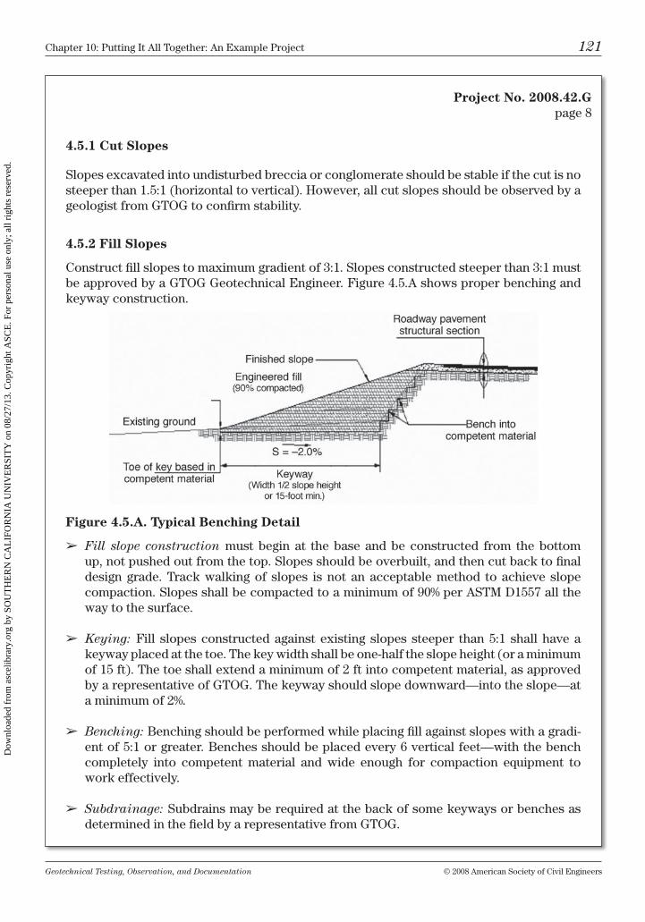
Geotechnical Testing, Observation, and Documentation © 2008 American Society of civil Engineers
chapter 10: Putting it All together: An Example Project 121
Project No. 2008.42.Gpage 8
4.5.1 Cut Slopes
Slopes excavated into undisturbed breccia or conglomerate should be stable if the cut is no steeper than 1.5:1 (horizontal to vertical). however, all cut slopes should be observed by a geologist from GtoG to confirm stability.
4.5.2 Fill Slopes
construct fill slopes to maximum gradient of 3:1. Slopes constructed steeper than 3:1 must be approved by a GtoG Geotechnical Engineer. Figure 4.5.A shows proper benching and keyway construction.
Figure 4.5.A. Typical Benching Detail
➢ Fill slope construction must begin at the base and be constructed from the bottom up, not pushed out from the top. Slopes should be overbuilt, and then cut back to final design grade. track walking of slopes is not an acceptable method to achieve slope compaction. Slopes shall be compacted to a minimum of 90% per AStm D1557 all the way to the surface.
➢ Keying: Fill slopes constructed against existing slopes steeper than 5:1 shall have a keyway placed at the toe. the key width shall be one-half the slope height (or a minimum of 15 ft). the toe shall extend a minimum of 2 ft into competent material, as approved by a representative of GtoG. the keyway should slope downward—into the slope—at a minimum of 2%.
➢ Benching: benching should be performed while placing fill against slopes with a gradi-ent of 5:1 or greater. benches should be placed every 6 vertical feet—with the bench completely into competent material and wide enough for compaction equipment to work effectively.
➢ Subdrainage: Subdrains may be required at the back of some keyways or benches as determined in the field by a representative from GtoG.
Dow
nloa
ded
from
asc
elib
rary
.org
by
SOU
TH
ER
N C
AL
IFO
RN
IA U
NIV
ER
SIT
Y o
n 08
/27/
13. C
opyr
ight
ASC
E. F
or p
erso
nal u
se o
nly;
all
righ
ts r
eser
ved.
Geotechnical Testing, Observation, and Documentation © 2008 American Society of civil Engineers
122 chapter 10: Putting it All together: An Example Project
Project No. 2008.42.Gpage 9
4.6 Surface Drainage
➢ Slope pavement areas a minimum of 2% toward drop inlets or other surface drainage collection devices.
➢ Slope finished grade away from building exteriors a minimum of 1% for a distance of at least 5 ft.
➢ Discharge roof downspouts a minimum of 3 ft away from building to appropriate sur-face drainage collection devices.
➢ construct v-ditches at the toe of slopes and add one v-ditch for every 20 vertical feet of slope. v-ditches may require rip-rap or concrete lining as determined by GtoG upon review of final plans.
5. Structural recommendations
5.1 Footings
We understand that the proposed construction will consist of one- or two-story, relatively light loaded wood frame buildings with dead plus live wall loads on the order of 1,000 to 2,000 pounds per lineal foot (plf); if structural loads in excess of these values are antici-pated, GtoG should be contacted to determine if modifications of these recommendations are necessary. A registered civil Engineer should design the foundations in accordance with the following recommendations.
5.1.1 Dimensions and Bearing Capacity
continuous strip footings and isolated spread footings are adequate for support of these structures if building pads are prepared in accordance with our Earthwork recommenda-tions herein (Section 4).
Single-Story Foundations
continuous Strip: 12 in. depth, 12 in. width
isolated Spread: 12 in. depth, 18 in. width
Two-Story Foundations
continuous Strip: 18 in. depth, 15 in. width
isolated Spread: 18 in. depth, 18 in. width
All depths are measured below the lowest adjacent soil/rock grade
Dow
nloa
ded
from
asc
elib
rary
.org
by
SOU
TH
ER
N C
AL
IFO
RN
IA U
NIV
ER
SIT
Y o
n 08
/27/
13. C
opyr
ight
ASC
E. F
or p
erso
nal u
se o
nly;
all
righ
ts r
eser
ved.
Geotechnical Testing, Observation, and Documentation © 2008 American Society of civil Engineers
chapter 10: Putting it All together: An Example Project 123
Project No. 2008.42.Gpage 10
Design the foundations recommended above for a maximum allowable bearing capacity of 2,500 pounds per square foot (psf) for dead plus live loads. increase the aforementioned capacity to 3,250 psf for the short-term effects of wind or seismic loading.
Prior to placing concrete:
• Thebottomoffoundationsshouldbearondenseundisturbednativesoil,bedrock,orengineered fill consistent with our Earthwork recommendations.
• Foundationsshouldnotspanbedrock/fillornative/fillcontacts;suchzonesmaycausedifferential support conditions and should be reviewed by our engineer for proper treatment.
• Footings shall be free of loose material, water, ice, or debris prior to concreteplacement.
• ArepresentativefromGTOGshouldobservethefootingofallexcavations.
5.1.2 Lateral Resistance
A combined lateral resistance from sliding friction and passive pressure can be used along the base and sides of foundations. use an allowable passive lateral earth pressure of 250 psf per foot of depth. calculate the sliding friction between the base of foundations and soil by using an allowable coefficient of friction of 0.40. these values include a factor of safety of approximately 1.5.
5.1.3 Settlement
based on the anticipated loads and our analysis, we estimate that total footing settlement resulting from static building loads should be less than ¾ in., with post-construction dif-ferential settlement on the order of ½ in.
5.2 Slabs on Grade
As a minimum for slab-on-grade construction we recommend the following:
1. Place at least 4 in. of ¾ in. minus clean crushed rock over the slab subgrade—then settle the rock into place with a minimum of two passes with a vibratory plate.
2. cover the crushed rock with a 10 mm polyethylene (or equivalent) vapor barrier.
3. Seal the vapor barrier at edges and utility and other penetrations.
Dow
nloa
ded
from
asc
elib
rary
.org
by
SOU
TH
ER
N C
AL
IFO
RN
IA U
NIV
ER
SIT
Y o
n 08
/27/
13. C
opyr
ight
ASC
E. F
or p
erso
nal u
se o
nly;
all
righ
ts r
eser
ved.
Geotechnical Testing, Observation, and Documentation © 2008 American Society of civil Engineers
124 chapter 10: Putting it All together: An Example Project
Project No. 2008.42.Gpage 11
4. Place 2 in. of sand over the polyethylene; moisten the sand prior to placing concrete.
5. locate the cold joint between the footing and slab at least 4 in. above the exterior finish grade elevation.
6. center 6 in. × 6 in. 10/10 (6 × 6 – W2.9 × W2.9) welded wire mesh horizontally in the slab. Support the mesh on dobie blocks; hooking and pulling up the mesh during placement is not acceptable.
7. use high-quality concrete with a water/cement ratio no higher than 0.55 for floor slabs and a minimum 28 day compressive strength of 3,000 psi.
8. All concrete should be tested in accordance with AStm standards by an Aci certified technician.
5.3 Exterior Concrete Flatwork
Exterior concrete flatwork, such as sidewalks and patios, should be a minimum of 4 in. thick. Prepare the subgrade as outlined in Section 4.1.1, and then place a 4 in. layer of caltrans class 2 Ab over the subgrade. compact the Ab to a minimum density of 95% per AStm D1557.
Flatwork concrete shall have a minimum compressive strength of 3,000 psi. to help control cracking, place expansion and crack control joints per recommendations of the Portland cement Association. All concrete should be tested in accordance with AStm standards by an Aci certified technician.
6. Pavement Design
We performed a laboratory resistance value (r value) test on the sandy silt in the northern site area. the r value for this material was 48. no r value test was performed on either the mehrten breccia or conglomerate. Should either of these materials be used for roadway subgrade, or should an approved import material be utilized, we recommend performing r value testing on each of the materials. We can then adjust our pavement section recom-mendations accordingly.
6.1 Flexible Pavements (Asphaltic Concrete)
We recommend the following pavement sections for traffic indexes 4 through 7, based on a design r value of 48.
Dow
nloa
ded
from
asc
elib
rary
.org
by
SOU
TH
ER
N C
AL
IFO
RN
IA U
NIV
ER
SIT
Y o
n 08
/27/
13. C
opyr
ight
ASC
E. F
or p
erso
nal u
se o
nly;
all
righ
ts r
eser
ved.
Geotechnical Testing, Observation, and Documentation © 2008 American Society of civil Engineers
chapter 10: Putting it All together: An Example Project 125
Project No. 2008.42.Gpage 12
Traffic Index (TI)
Asphalt Concrete (inches)
Aggregate Base (inches)
4 2 6
5 2.5 6
6 3 7
7 3.5 8
Asphalt concrete paving shall conform to caltrans Standard Specifications Section 39, for type b. Subgrade shall be prepared as outlined in Section 4.1.1 and compacted to a mini-mum of 95% per AStm D1557. use caltrans class 2 Ab in flexible pavement sections. the Ab shall be compacted to a minimum of 95% per AStm D1557 at a moisture content of between –1% and +2% of optimum moisture.
6.2 Rigid Pavements (Reinforced Concrete)
use rigid Portland cement concrete pavement sections to resist heavy loads and turning forces in areas such as loading docks or lanes, fire lanes, and around trash enclosures. Final design of rigid pavement sections and reinforcement should be performed based on actual traffic loads and frequencies.
use caltrans class 2 Ab in rigid pavement sections. the Ab shall be compacted to a mini-mum of 95% per AStm D1557 at a moisture content of between –1% and +2% of optimum moisture. Prior to placing Ab the subgrade shall be prepared as outlined in Section 4.1.1 and compacted to a minimum of 95% per AStm D1557. We recommend at a minimum the use of 6 in. of Portland cement concrete over 6 in. of Ab. the Portland cement concrete should have a minimum 28 day compressive strength of 4,000 psi and have 6 in. × 6 in. 10/10 welded wire mesh centered horizontally in the concrete.
All concrete should be tested in accordance with AStm standards by an Aci certified technician.
Dow
nloa
ded
from
asc
elib
rary
.org
by
SOU
TH
ER
N C
AL
IFO
RN
IA U
NIV
ER
SIT
Y o
n 08
/27/
13. C
opyr
ight
ASC
E. F
or p
erso
nal u
se o
nly;
all
righ
ts r
eser
ved.

Geotechnical Testing, Observation, and Documentation © 2008 American Society of civil Engineers
126 chapter 10: Putting it All together: An Example Project
Project No. 2008.42.Gpage 13
Figures
Figure 1 Site vicinity map
Figure 2 Site Plan with trench and boring locations
Dow
nloa
ded
from
asc
elib
rary
.org
by
SOU
TH
ER
N C
AL
IFO
RN
IA U
NIV
ER
SIT
Y o
n 08
/27/
13. C
opyr
ight
ASC
E. F
or p
erso
nal u
se o
nly;
all
righ
ts r
eser
ved.
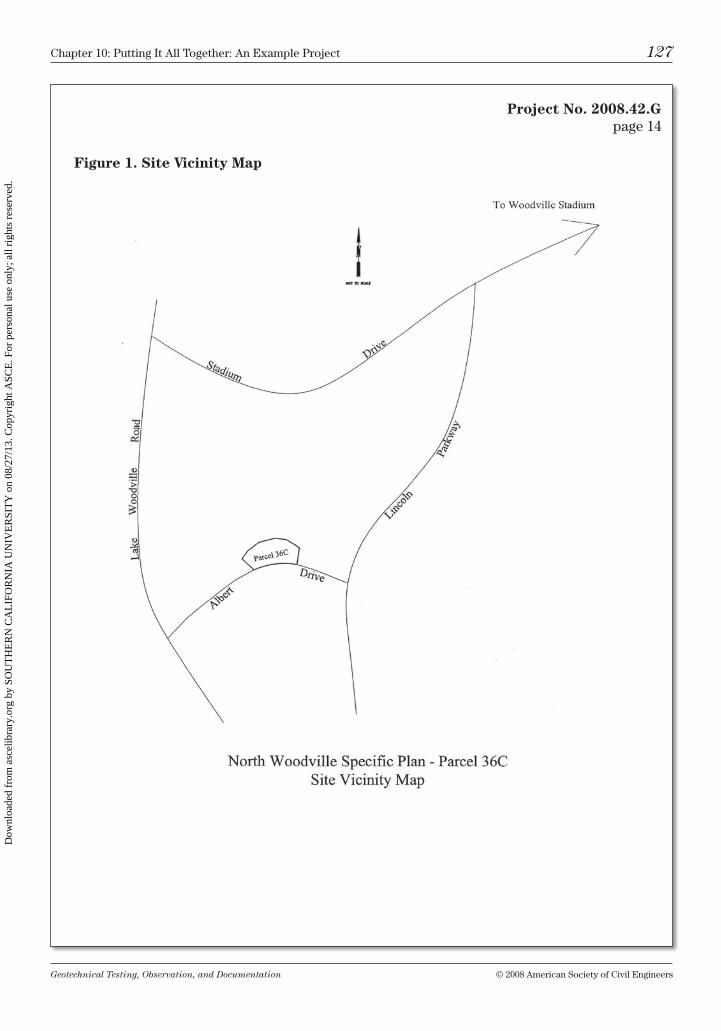
Geotechnical Testing, Observation, and Documentation © 2008 American Society of civil Engineers
chapter 10: Putting it All together: An Example Project 127
Project No. 2008.42.Gpage 14
Figure 1. Site Vicinity Map
Dow
nloa
ded
from
asc
elib
rary
.org
by
SOU
TH
ER
N C
AL
IFO
RN
IA U
NIV
ER
SIT
Y o
n 08
/27/
13. C
opyr
ight
ASC
E. F
or p
erso
nal u
se o
nly;
all
righ
ts r
eser
ved.
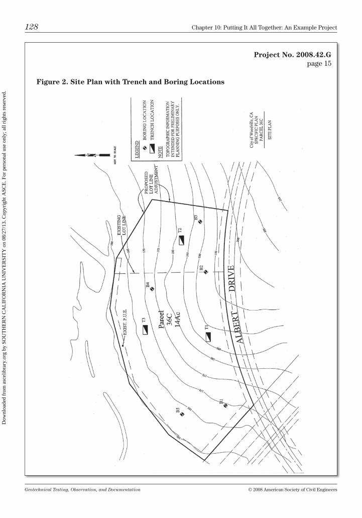
Geotechnical Testing, Observation, and Documentation © 2008 American Society of civil Engineers
128 chapter 10: Putting it All together: An Example Project
Project No. 2008.42.Gpage 15
Figure 2. Site Plan with Trench and Boring Locations
Dow
nloa
ded
from
asc
elib
rary
.org
by
SOU
TH
ER
N C
AL
IFO
RN
IA U
NIV
ER
SIT
Y o
n 08
/27/
13. C
opyr
ight
ASC
E. F
or p
erso
nal u
se o
nly;
all
righ
ts r
eser
ved.
Geotechnical Testing, Observation, and Documentation © 2008 American Society of civil Engineers
chapter 10: Putting it All together: An Example Project 129
Project No. 2008.42.Gpage 16
Appendices
Appendix A trench logsAppendix b boring logsAppendix c laboratory test results
Dow
nloa
ded
from
asc
elib
rary
.org
by
SOU
TH
ER
N C
AL
IFO
RN
IA U
NIV
ER
SIT
Y o
n 08
/27/
13. C
opyr
ight
ASC
E. F
or p
erso
nal u
se o
nly;
all
righ
ts r
eser
ved.
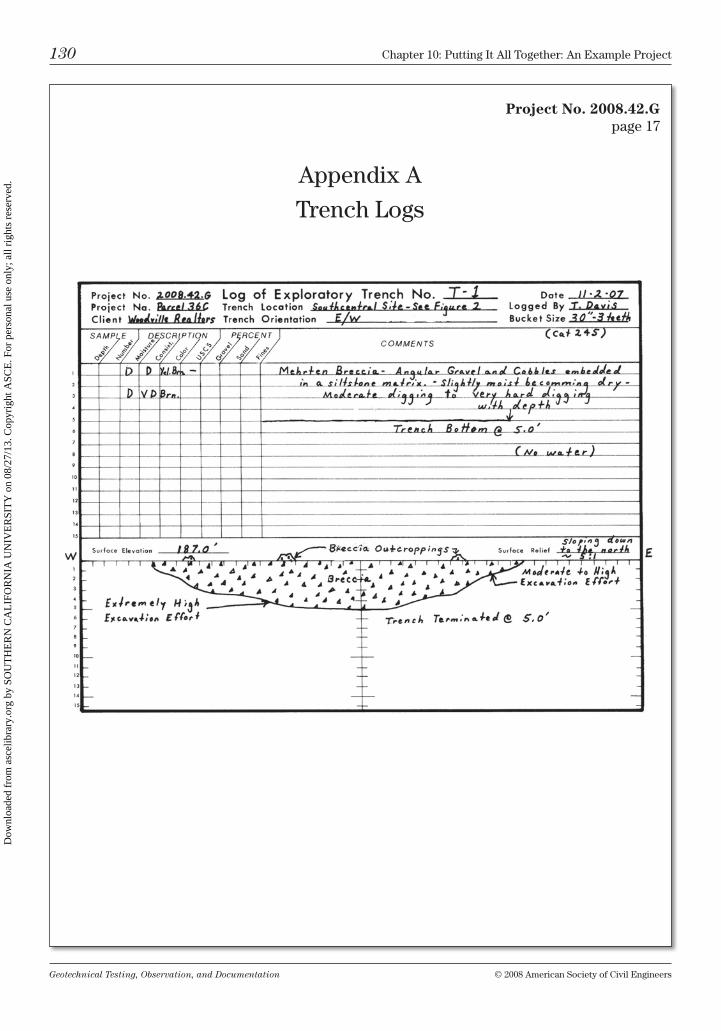
Geotechnical Testing, Observation, and Documentation © 2008 American Society of civil Engineers
130 chapter 10: Putting it All together: An Example Project
Project No. 2008.42.Gpage 17
Appendix A
trench logs
Dow
nloa
ded
from
asc
elib
rary
.org
by
SOU
TH
ER
N C
AL
IFO
RN
IA U
NIV
ER
SIT
Y o
n 08
/27/
13. C
opyr
ight
ASC
E. F
or p
erso
nal u
se o
nly;
all
righ
ts r
eser
ved.
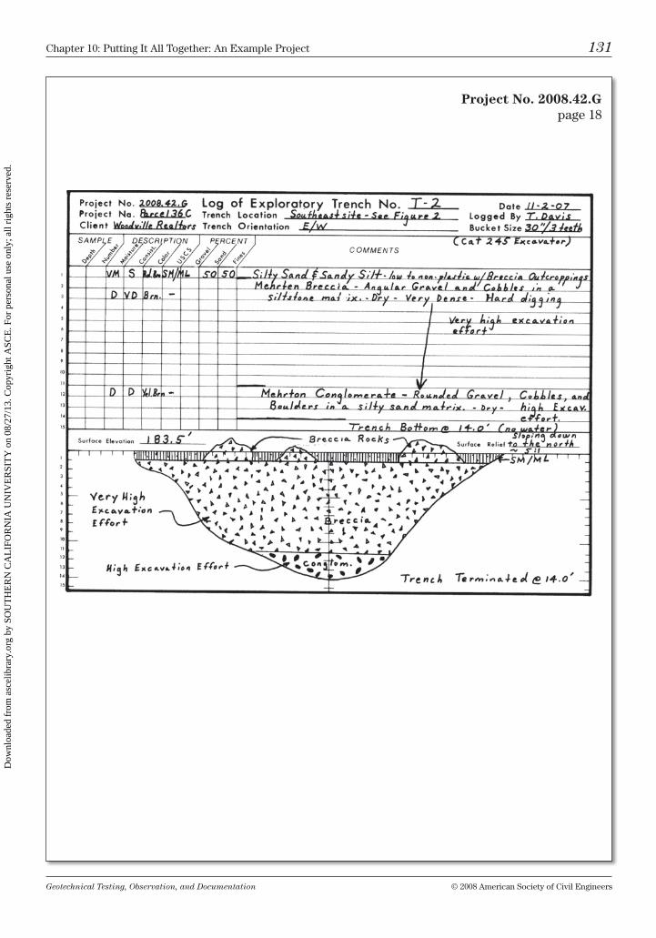
Geotechnical Testing, Observation, and Documentation © 2008 American Society of civil Engineers
chapter 10: Putting it All together: An Example Project 131
Project No. 2008.42.Gpage 18
Dow
nloa
ded
from
asc
elib
rary
.org
by
SOU
TH
ER
N C
AL
IFO
RN
IA U
NIV
ER
SIT
Y o
n 08
/27/
13. C
opyr
ight
ASC
E. F
or p
erso
nal u
se o
nly;
all
righ
ts r
eser
ved.
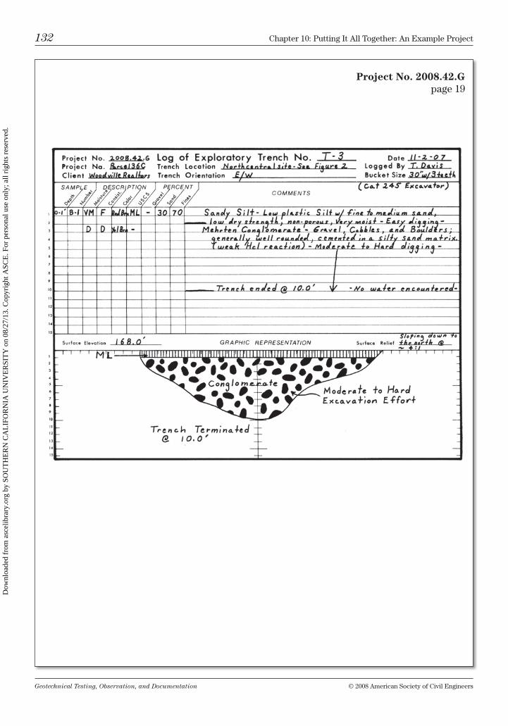
Geotechnical Testing, Observation, and Documentation © 2008 American Society of civil Engineers
132 chapter 10: Putting it All together: An Example Project
Project No. 2008.42.Gpage 19
Dow
nloa
ded
from
asc
elib
rary
.org
by
SOU
TH
ER
N C
AL
IFO
RN
IA U
NIV
ER
SIT
Y o
n 08
/27/
13. C
opyr
ight
ASC
E. F
or p
erso
nal u
se o
nly;
all
righ
ts r
eser
ved.
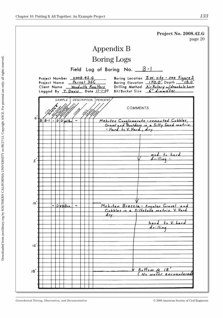
Geotechnical Testing, Observation, and Documentation © 2008 American Society of civil Engineers
chapter 10: Putting it All together: An Example Project 133
Project No. 2008.42.Gpage 20
Appendix b
boring logs
Dow
nloa
ded
from
asc
elib
rary
.org
by
SOU
TH
ER
N C
AL
IFO
RN
IA U
NIV
ER
SIT
Y o
n 08
/27/
13. C
opyr
ight
ASC
E. F
or p
erso
nal u
se o
nly;
all
righ
ts r
eser
ved.
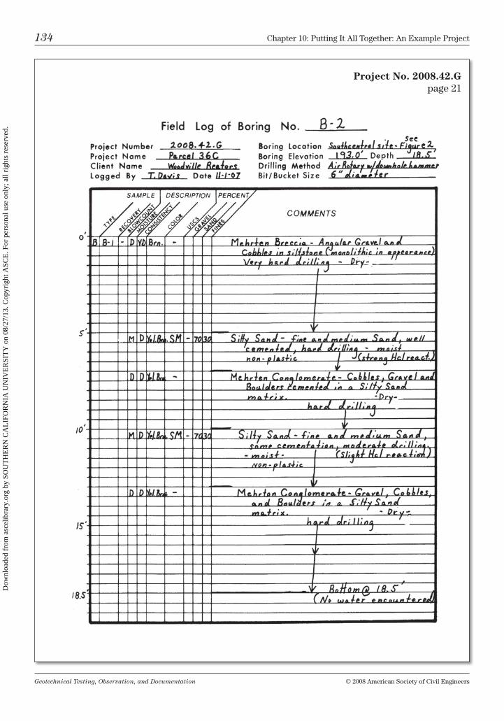
Geotechnical Testing, Observation, and Documentation © 2008 American Society of civil Engineers
134 chapter 10: Putting it All together: An Example Project
Project No. 2008.42.Gpage 21
Dow
nloa
ded
from
asc
elib
rary
.org
by
SOU
TH
ER
N C
AL
IFO
RN
IA U
NIV
ER
SIT
Y o
n 08
/27/
13. C
opyr
ight
ASC
E. F
or p
erso
nal u
se o
nly;
all
righ
ts r
eser
ved.
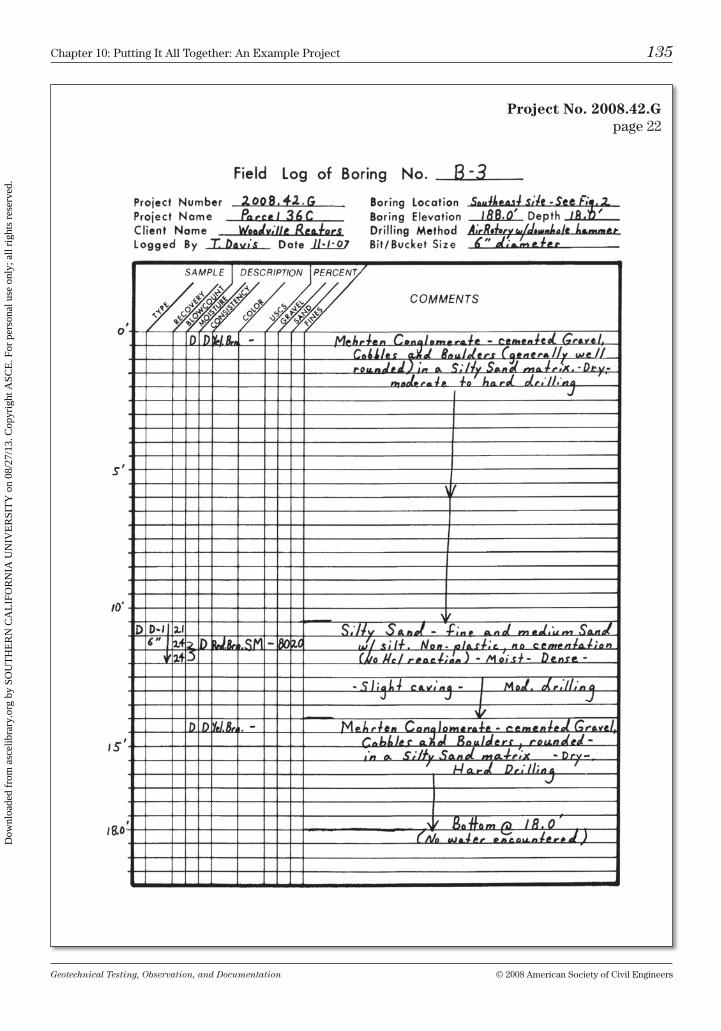
Geotechnical Testing, Observation, and Documentation © 2008 American Society of civil Engineers
chapter 10: Putting it All together: An Example Project 135
Project No. 2008.42.Gpage 22
Dow
nloa
ded
from
asc
elib
rary
.org
by
SOU
TH
ER
N C
AL
IFO
RN
IA U
NIV
ER
SIT
Y o
n 08
/27/
13. C
opyr
ight
ASC
E. F
or p
erso
nal u
se o
nly;
all
righ
ts r
eser
ved.
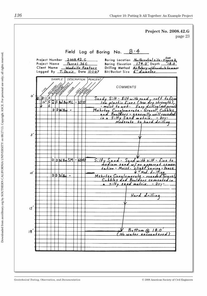
Geotechnical Testing, Observation, and Documentation © 2008 American Society of civil Engineers
136 chapter 10: Putting it All together: An Example Project
Project No. 2008.42.Gpage 23
Dow
nloa
ded
from
asc
elib
rary
.org
by
SOU
TH
ER
N C
AL
IFO
RN
IA U
NIV
ER
SIT
Y o
n 08
/27/
13. C
opyr
ight
ASC
E. F
or p
erso
nal u
se o
nly;
all
righ
ts r
eser
ved.
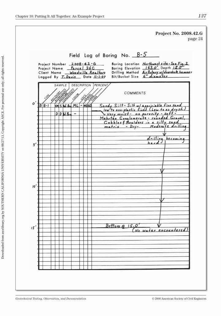
Geotechnical Testing, Observation, and Documentation © 2008 American Society of civil Engineers
chapter 10: Putting it All together: An Example Project 137
Project No. 2008.42.Gpage 24
Dow
nloa
ded
from
asc
elib
rary
.org
by
SOU
TH
ER
N C
AL
IFO
RN
IA U
NIV
ER
SIT
Y o
n 08
/27/
13. C
opyr
ight
ASC
E. F
or p
erso
nal u
se o
nly;
all
righ
ts r
eser
ved.
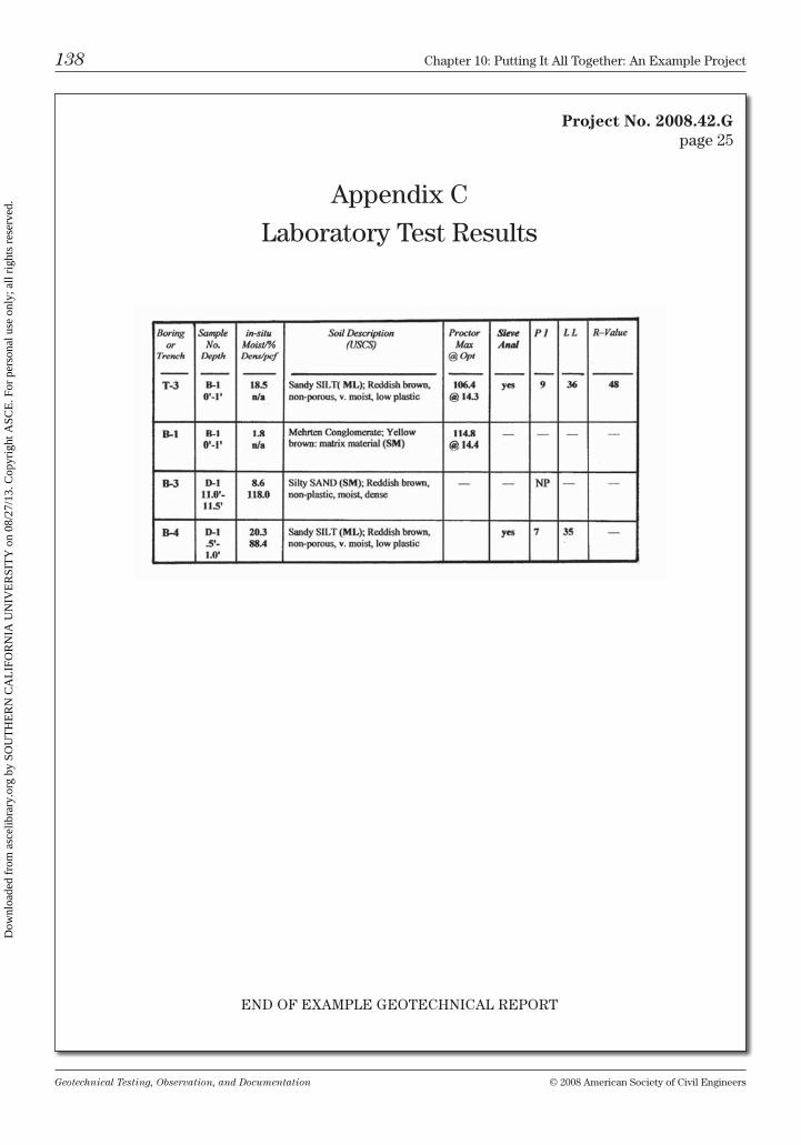
Geotechnical Testing, Observation, and Documentation © 2008 American Society of civil Engineers
138 chapter 10: Putting it All together: An Example Project
Project No. 2008.42.Gpage 25
Appendix c
laboratory test results
EnD oF EXAmPlE GEotEchnicAl rEPort
Dow
nloa
ded
from
asc
elib
rary
.org
by
SOU
TH
ER
N C
AL
IFO
RN
IA U
NIV
ER
SIT
Y o
n 08
/27/
13. C
opyr
ight
ASC
E. F
or p
erso
nal u
se o
nly;
all
righ
ts r
eser
ved.
Geotechnical Testing, Observation, and Documentation © 2008 American Society of civil Engineers
chapter 10: Putting it All together: An Example Project 139
chapter Questions
1. What type of recommendation would not typically be included in a geotechnical report?A) Pavement thicknessb) Degree of compactionc) height of the structureD) Footing depth and width
2. Which item is the most important to be performed before any under-ground work is started?A) Draw a sketch of the site.b) have existing underground utilities located.c) Decide how many boreholes you will need to drill.D) Set up a pre-grade meeting.
Refer to the Example Geotechnical Report for Questions 3 through 8.
3. In the Earthwork Recommendations section, which of the following type of soil or conditions was not addressed?A) rock fillb) transition padsc) Expansive soilD) on-site materialE) none of above
4. According to the boring and trench logs, at a depth of 1 ft or deeper in the southern portion of the site, expansive soils are expected to be encountered.A) trueb) False
5. Cut slopes excavated into undisturbed Mehrten breccia or conglom-erate should be stable if cut no steeper than 1:1.A) trueb) False
6. Regarding fill slopes, which one of the following statements is false?A) if a keyway is placed at the toe of a 3:1 slope no benching is necessary
while placing the rest of the slope fill.b) Fill slopes must be built from the bottom up—not pushed out from the
top.c) track walking slopes for compaction is not acceptable.D) the keyway shall be a minimum of 15 ft wide and sloped downward into
the slope at 2%.
Dow
nloa
ded
from
asc
elib
rary
.org
by
SOU
TH
ER
N C
AL
IFO
RN
IA U
NIV
ER
SIT
Y o
n 08
/27/
13. C
opyr
ight
ASC
E. F
or p
erso
nal u
se o
nly;
all
righ
ts r
eser
ved.
Geotechnical Testing, Observation, and Documentation © 2008 American Society of civil Engineers
140 chapter 10: Putting it All together: An Example Project
7. Rock fill placement recommendations shall apply if more than 30% of the material is larger than the 4-in. sieve.A) trueb) False
8. To reduce the potential for differential settlement on this project each pad shall be over-excavated a minimum of 36 in. and replaced with engineered fill.A) trueb) False
9. In preparation for a project—just before grading—it is wise to pick up samples of both native and import soils (if known) for Proctor samples.A) trueb) False
10. The sequence of density tests on a project must be started over on a daily basis beginning at number 1.A) trueb) False
11. Density test number 142 failed last week, but a retest taken at the same location today passed; however, the last passing test number is now number 215. What is the proper designation for a passing retest of number 142?A) 215rb) 142rc) 216D) none of the above
Dow
nloa
ded
from
asc
elib
rary
.org
by
SOU
TH
ER
N C
AL
IFO
RN
IA U
NIV
ER
SIT
Y o
n 08
/27/
13. C
opyr
ight
ASC
E. F
or p
erso
nal u
se o
nly;
all
righ
ts r
eser
ved.
Geotechnical Testing, Observation, and Documentation © 2008 American Society of civil Engineers 141
A Technician’s Quick Reference
being prepared with the right tools makes the job easier, and using the proper equipment contributes to more accurate results. Delays on both sampling and testing will result when the technician is not properly prepared. Figure 11-1 shows some of the equipment and supplies used by technicians.
the right choice of compaction Equipment
the type of equipment used for compaction greatly influences the ability to obtain adequate compaction. in fact, when the wrong equipment is used for specific soil conditions acceptable compaction often cannot be achieved. For instance, using a small plate whacker for compacting a 6-in. layer of aggregate base is not appropriate; nevertheless, contractors will often try to use a small plate whacker for compacting fill deeper than the machine is capable of doing.
A geotechnical report often may not make recommendations on the type of compaction equipment to use. When specific equipment recommendations are not given in the report, do not direct the contractor on equipment type; just observe and document the contractor’s work.
if recommendations are given in the geotechnical report as to the type of com-paction equipment to be used (or not to be used!) for certain soil conditions, then it is the technician’s job to discuss the choice of equipment with the con-tractor. Should the contractor continue to use equipment not recommended, the technician should immediately inform the project engineer.
remember, should the wrong compaction methods be used, a good way to point this out to the contractor is through a density test failure. tables 11-2 and 11-3 indicate which types of compaction equipment are generally best for each soil or material condition. Figure 11-4 shows several different types of compaction equipment.
11
Dow
nloa
ded
from
asc
elib
rary
.org
by
SOU
TH
ER
N C
AL
IFO
RN
IA U
NIV
ER
SIT
Y o
n 08
/27/
13. C
opyr
ight
ASC
E. F
or p
erso
nal u
se o
nly;
all
righ
ts r
eser
ved.
Geotechnical Testing, Observation, and Documentation © 2008 American Society of civil Engineers
142 chapter 11: A technician’s Quick reference
basic checklist of a technician’s
Supplies and tools
the following lists many basic tools necessary to perform a field technician’s job.
reference material: International Building Code (shown in Fig. 11-1), project geotechni-cal report, a dictionary, Pocket Reference by thomas J. Glover, oShA standards, and other federal and local standards.
Sieves: At a minimum carry a #4 and a ¾-in. screen for rock corrections when comparing field density tests to the laboratory Proctor (per AStm D1557).
measuring tapes: it is handy to carry various lengths of tape; often a measuring wheel is valuable when measuring large distances on generally flat ground and a folding rule (shown in Fig. 11-1) is best to use with the peep site (hand level), which is shown in the lower center of Fig. 11-1.
Plastic bags and labels: various sizes of plastic bags are useful, with large ones for Proctor samples and small ones for when less material is needed for lab testing. Plastic or metal buckets may also be handy.
maps and plans: State and local maps, project plans, and a good compass to help orient you on the project site.
Probe and pocket penetrometer: the probe (shown in Fig. 11-1) is a technician’s best tool—use it! A pocket penetrometer is handy for testing trench walls for consistency (per oShA cohesive soil classification for trench walls, Excavations, Subpart P).
thermometers: An infrared thermometer (as shown in Fig. 11-1) is handy for taking sur-face readings; however, the standard metal probe mercury thermometer should still gen-erally be used for concrete and other liquid readings.
hardhat and safety vest: have extra surveyor’s lath and bright-colored surveyor’s ribbon for placing near your density test location as extra warning.
Sand cone or nuclear gauge: carry all supplies for testing equipment, including a flat-head shovel, calibrated density sand, sand cone digging tools, scale(s), and moisture burn-out supplies.
Drafting and writing supplies: engineer’s ruler, triangle, calculator, pens, pencils, colored highlighters, paper clips, etc.
modified Proctor equipment: Such equipment is necessary for pounding one-point “check points” to confirm use of the right lab Proctor in the field.
miscellaneous items: shovel, marking paint, surveyor’s tape (shown in the upper right of Fig. 11-1), geologist pick (also shown in Fig. 11-1), small sledge hammer, and anything else needed on a per-job basis.
Dow
nloa
ded
from
asc
elib
rary
.org
by
SOU
TH
ER
N C
AL
IFO
RN
IA U
NIV
ER
SIT
Y o
n 08
/27/
13. C
opyr
ight
ASC
E. F
or p
erso
nal u
se o
nly;
all
righ
ts r
eser
ved.

Geotechnical Testing, Observation, and Documentation © 2008 American Society of civil Engineers
chapter 11: A technician’s Quick reference 143
Some tools of the trade. Figure 11-1
Compaction for general grading operations. Table 11-2
Soil or material type Compaction equipment
Sandy and Gravelly nonplastic soils (SW, SP, Sm, GW, GP, Gm)
Most types of compaction equipment rubber-tired, sheepsfoot (vibratory and non-vibe), flat-drum vibe roller
Sand–Clay–Silt mixes low/med plastic (Sc, Sm, Gc, Gm, Sm/ml, Sc/cl)
large rubber-tired equipment, heavy sheepsfoot (non-vibe)
Clay and Silt–Clay mixes med/high plas-tic with little or no coarse material (cl, ch, ml, mh, Sc/cl)
large rubber-tired equipment, heavy sheepsfoot (non-vibe)
Aggregate Base for roadway (GP, Gm) Flat-drum vibratory roller
Rock Fills: generally untestable mate-rial with nonplastic matrix soil (full-time observation only)
All large/heavy compaction equipment Sheepsfoot (vibe or non-vibe), track walked/mixed by D9 dozer (equivalent or larger)
Dow
nloa
ded
from
asc
elib
rary
.org
by
SOU
TH
ER
N C
AL
IFO
RN
IA U
NIV
ER
SIT
Y o
n 08
/27/
13. C
opyr
ight
ASC
E. F
or p
erso
nal u
se o
nly;
all
righ
ts r
eser
ved.
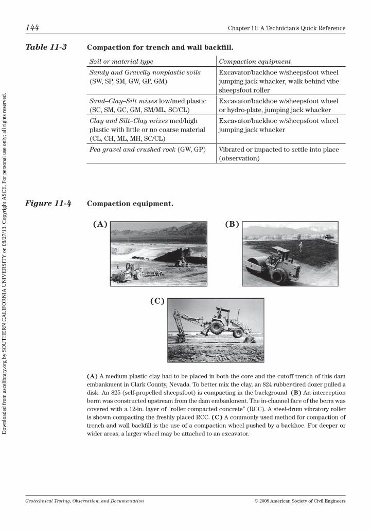
Geotechnical Testing, Observation, and Documentation © 2008 American Society of civil Engineers
144 chapter 11: A technician’s Quick reference
Table 11-3 Compaction for trench and wall backfill.
Soil or material type Compaction equipment
Sandy and Gravelly nonplastic soils (SW, SP, Sm, GW, GP, Gm)
Excavator/backhoe w/sheepsfoot wheel jumping jack whacker, walk behind vibe sheepsfoot roller
Sand–Clay–Silt mixes low/med plastic (Sc, Sm, Gc, Gm, Sm/ml, Sc/cl)
Excavator/backhoe w/sheepsfoot wheel or hydro-plate, jumping jack whacker
Clay and Silt–Clay mixes med/high plastic with little or no coarse material (cl, ch, ml, mh, Sc/cl)
Excavator/backhoe w/sheepsfoot wheel jumping jack whacker
Pea gravel and crushed rock (GW, GP) vibrated or impacted to settle into place (observation)
Figure 11-4 Compaction equipment.
(A) A medium plastic clay had to be placed in both the core and the cutoff trench of this dam embankment in clark county, nevada. to better mix the clay, an 824 rubber-tired dozer pulled a disk. An 825 (self-propelled sheepsfoot) is compacting in the background. (B) An interception berm was constructed upstream from the dam embankment. the in-channel face of the berm was covered with a 12-in. layer of “roller compacted concrete” (rcc). A steel-drum vibratory roller is shown compacting the freshly placed rcc. (C) A commonly used method for compaction of trench and wall backfill is the use of a compaction wheel pushed by a backhoe. For deeper or wider areas, a larger wheel may be attached to an excavator.
(A) (B)
(C)
Dow
nloa
ded
from
asc
elib
rary
.org
by
SOU
TH
ER
N C
AL
IFO
RN
IA U
NIV
ER
SIT
Y o
n 08
/27/
13. C
opyr
ight
ASC
E. F
or p
erso
nal u
se o
nly;
all
righ
ts r
eser
ved.
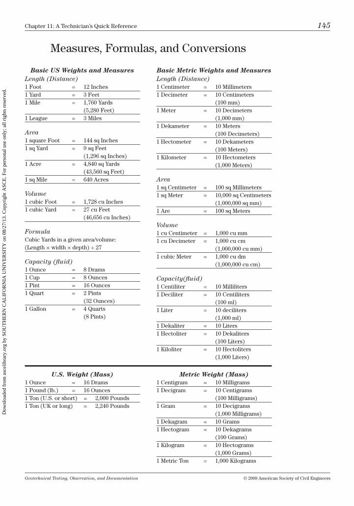
Geotechnical Testing, Observation, and Documentation © 2008 American Society of civil Engineers
chapter 11: A technician’s Quick reference 145
measures, Formulas, and conversions
Basic US Weights and MeasuresLength (Distance)1 Foot = 12 inches1 yard = 3 Feet1 mile = 1,760 yards (5,280 Feet)1 league = 3 miles
Area1 square Foot = 144 sq inches1 sq yard = 9 sq Feet (1,296 sq inches)1 Acre = 4,840 sq yards (43,560 sq Feet)1 sq mile = 640 Acres
Volume1 cubic Foot = 1,728 cu inches1 cubic yard = 27 cu Feet (46,656 cu inches)
Formulacubic yards in a given area/volume: (length × width × depth) ÷ 27
Capacity (fluid)1 ounce = 8 Drams1 cup = 8 ounces1 Pint = 16 ounces1 Quart = 2 Pints (32 ounces)1 Gallon = 4 Quarts (8 Pints)
Basic Metric Weights and MeasuresLength (Distance)1 centimeter = 10 millimeters1 Decimeter = 10 centimeters (100 mm)1 meter = 10 Decimeters (1,000 mm)1 Dekameter = 10 meters (100 Decimeters)1 hectometer = 10 Dekameters (100 meters)1 kilometer = 10 hectometers (1,000 meters)
Area1 sq centimeter = 100 sq millimeters1 sq meter = 10,000 sq centimeters (1,000,000 sq mm)1 Are = 100 sq meters
Volume1 cu centimeter = 1,000 cu mm1 cu Decimeter = 1,000 cu cm (1,000,000 cu mm)1 cubic meter = 1,000 cu dm (1,000,000 cu cm)
Capacity(fluid)1 centiliter = 10 milliliters1 Deciliter = 10 centiliters (100 ml)1 liter = 10 deciliters (1,000 ml)1 Dekaliter = 10 liters1 hectoliter = 10 Dekaliters (100 liters)1 kiloliter = 10 hectoliters (1,000 liters)
U.S. Weight (Mass)1 ounce = 16 Drams1 Pound (lb.) = 16 ounces 1 ton (u.S. or short) = 2,000 Pounds1 ton (uk or long) = 2,240 Pounds
Metric Weight (Mass)1 centigram = 10 milligrams1 Decigram = 10 centigrams (100 milligrams)1 Gram = 10 Decigrams (1,000 milligrams)1 Dekagram = 10 Grams1 hectogram = 10 Dekagrams (100 Grams)1 kilogram = 10 hectograms (1,000 Grams)1 metric ton = 1,000 kilograms
Dow
nloa
ded
from
asc
elib
rary
.org
by
SOU
TH
ER
N C
AL
IFO
RN
IA U
NIV
ER
SIT
Y o
n 08
/27/
13. C
opyr
ight
ASC
E. F
or p
erso
nal u
se o
nly;
all
righ
ts r
eser
ved.
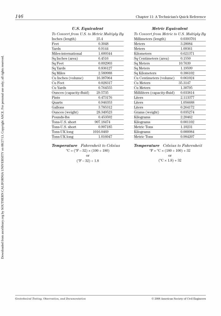
Geotechnical Testing, Observation, and Documentation © 2008 American Society of civil Engineers
146 chapter 11: A technician’s Quick reference
U.S. EquivalentTo Convert from U.S. to Metric Multiply Byinches (length) 25.4Feet 0.3048yards 0.9144miles-international 1.609344Sq inches (area) 6.4516Sq Feet 0.092903Sq yards 0.836127Sq miles 2.589988cu inches (volume) 16.387064cu Feet 0.028317cu yards 0.764555ounces (capacity-fluid) 29.5735Pints 0.473176Quarts 0.946353Gallons 3.785312ounces (weight) 28.349523Pounds-lbs 0.453592tons-u.S. short 907.18474tons-u.S. short 0.907185tons-uk long 1016.0469tons-uk long 1.016047
Temperature Fahrenheit to Celsiusºc = (ºF – 32) × (100 ÷ 180)
or
(ºF – 32) ÷ 1.8
Metric EquivalentTo Convert from Metric to U.S. Multiply Bymillimeters (length) 0.0393701meters 3.28084meters 1.09361kilometers 0.621371Sq centimeters (area) 0.1550Sq meters 10.7639Sq meters 1.19599Sq kilometers 0.386102cu centimeters (volume) 0.061024cu meters 35.3147cu meters 1.30795milliliters (capacity-fluid) 0.033814liters 2.113377liters 1.056688liters 0.264172Grams (weight) 0.035274kilograms 2.20462kilograms 0.001102metric tons 1.10231kilograms 0.000984metric tons 0.984207
Temperature Celsius to FahrenheitºF = ºc × (180 ÷ 100) + 32
or (ºc × 1.8) + 32
Dow
nloa
ded
from
asc
elib
rary
.org
by
SOU
TH
ER
N C
AL
IFO
RN
IA U
NIV
ER
SIT
Y o
n 08
/27/
13. C
opyr
ight
ASC
E. F
or p
erso
nal u
se o
nly;
all
righ
ts r
eser
ved.
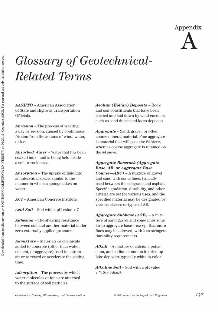
Geotechnical Testing, Observation, and Documentation © 2008 American Society of civil Engineers 147
Appendix
AGlossary of Geotechnical- Related Terms
AASHTO – American Association of State and highway transportation officials.
Abrasion – the process of wearing away by erosion, caused by continuous friction from the actions of wind, water, or ice.
Absorbed Water – Water that has been soaked into—and is being held inside— a soil or rock mass.
Absorption – the uptake of fluid into an interstitial space, similar to the manner in which a sponge takes on water.
ACI – American concrete institute.
Acid Soil – Soil with a ph value < 7.
Adhesion – the shearing resistance between soil and another material under zero externally applied pressure.
Admixture – materials or chemicals added to concrete (other than water, cement, or aggregate) used to entrain air or to retard or accelerate the setting time.
Adsorption – the process by which water molecules or ions are attached to the surface of soil particles.
Aeolian (Eolian) Deposits – rock and soil constituents that have been carried and laid down by wind currents, such as sand dunes and loess deposits.
Aggregate – Sand, gravel, or other coarse mineral material. Fine aggregate is material that will pass the #4 sieve, whereas coarse aggregate is retained on the #4 sieve.
Aggregate Baserock (Aggregate Base, AB, or Aggregate Base Course—ABC) – A mixture of gravel and sand with some fines; typically used between the subgrade and asphalt. Specific gradation, durability, and other criteria are set for various uses, and the specified material may be designated by various classes or types of Ab.
Aggregate Subbase (ASB) – A mix-ture of sand gravel and some fines simi-lar to aggregate base—except that more fines may be allowed, with less-stringent durability requirements.
Alkali – A mixture of calcium, potas-sium, and sodium common in dried-up lake deposits; typically white in color.
Alkaline Soil – Soil with a ph value > 7. See Alkali.
Dow
nloa
ded
from
asc
elib
rary
.org
by
SOU
TH
ER
N C
AL
IFO
RN
IA U
NIV
ER
SIT
Y o
n 08
/27/
13. C
opyr
ight
ASC
E. F
or p
erso
nal u
se o
nly;
all
righ
ts r
eser
ved.
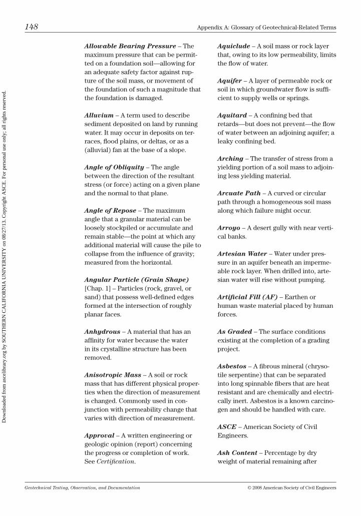
Geotechnical Testing, Observation, and Documentation © 2008 American Society of civil Engineers
148 Appendix A: Glossary of Geotechnical-related terms
Allowable Bearing Pressure – the maximum pressure that can be permit-ted on a foundation soil—allowing for an adequate safety factor against rup-ture of the soil mass, or movement of the foundation of such a magnitude that the foundation is damaged.
Alluvium – A term used to describe sediment deposited on land by running water. it may occur in deposits on ter-races, flood plains, or deltas, or as a (alluvial) fan at the base of a slope.
Angle of Obliquity – the angle between the direction of the resultant stress (or force) acting on a given plane and the normal to that plane.
Angle of Repose – the maximum angle that a granular material can be loosely stockpiled or accumulate and remain stable—the point at which any additional material will cause the pile to collapse from the influence of gravity; measured from the horizontal.
Angular Particle (Grain Shape) [chap. 1] – Particles (rock, gravel, or sand) that possess well-defined edges formed at the intersection of roughly planar faces.
Anhydrous – A material that has an affinity for water because the water in its crystalline structure has been removed.
Anisotropic Mass – A soil or rock mass that has different physical proper-ties when the direction of measurement is changed. commonly used in con-junction with permeability change that varies with direction of measurement.
Approval – A written engineering or geologic opinion (report) concerning the progress or completion of work. See Certification.
Aquiclude – A soil mass or rock layer that, owing to its low permeability, limits the flow of water.
Aquifer – A layer of permeable rock or soil in which groundwater flow is suffi-cient to supply wells or springs.
Aquitard – A confining bed that retards—but does not prevent—the flow of water between an adjoining aquifer; a leaky confining bed.
Arching – the transfer of stress from a yielding portion of a soil mass to adjoin-ing less yielding material.
Arcuate Path – A curved or circular path through a homogeneous soil mass along which failure might occur.
Arroyo – A desert gully with near verti-cal banks.
Artesian Water – Water under pres-sure in an aquifer beneath an imperme-able rock layer. When drilled into, arte-sian water will rise without pumping.
Artificial Fill (AF) – Earthen or human waste material placed by human forces.
As Graded – the surface conditions existing at the completion of a grading project.
Asbestos – A fibrous mineral (chryso-tile serpentine) that can be separated into long spinnable fibers that are heat resistant and are chemically and electri-cally inert. Asbestos is a known carcino-gen and should be handled with care.
ASCE – American Society of civil Engineers.
Ash Content – Percentage by dry weight of material remaining after
Dow
nloa
ded
from
asc
elib
rary
.org
by
SOU
TH
ER
N C
AL
IFO
RN
IA U
NIV
ER
SIT
Y o
n 08
/27/
13. C
opyr
ight
ASC
E. F
or p
erso
nal u
se o
nly;
all
righ
ts r
eser
ved.
Geotechnical Testing, Observation, and Documentation © 2008 American Society of civil Engineers
Appendix A: Glossary of Geotechnical-related terms 149
organic soil (such as peat) is burned by a standardized method.
Asphalt (AC) – A dark brown to black cementitious material, solid or semisolid in consistency, in which the predominat-ing constituents are bitumens that occur in nature or are obtained as residue in refining petroleum.
ASTM (American Society for Test-ing and Materials) International – organized in 1898, AStm has grown into one of the largest voluntary stan-dards development systems in the world. AStm members write standards for materials, products, and services, including methods for performing soils and materials tests, each of which are described in detail in their annual books of standards.
Attenuation – the reduction of ampli-tude with time and distance.
Atterberg Limits Test [chap. 3] – (1) current usage refers to the liquid limit, plastic limit, and the plasticity index for properties of silty and clayey soils. (refer to AStm D4318.) (2) originally described by Albert Atter-berg in 1912 as the collective designa-tion of “seven limits of consistency” of fine grained soils.
Auger – A spiral shaped tool (which may vary in length) used to drill soil or soft rock. may be solid or hollow stemmed; the hollow-stem type allows for sampling without removing the auger from the borehole.
Back cut – the face of an excavated slope prior to the placement of fill, wall, or other structure against it.
Backfill – (1) the process of placing material back into an excavation. (2) the material used to refill an excavation.
Basalt – A very fine grained dark gray or black volcanic rock, often with gas bubbles or vesicles.
Base Key – See Key.
Base Rock (Basecourse/Base Course) – See Aggregate Baserock.
Bearing – the stress between a founda-tion and its support; the load carried by the supporting material.
Bearing Pile – A pile that carries weight (load), as opposed to earth pressure (friction).
Bearing Value – the load on a bearing surface divided by its area.
Bearing Wall – the structural wall that supports part of the load from above and transfers the load down to a lower floor or footing.
Bedding – (1) Stratum of sedimentary rock exhibiting surfaces of separation (bedding planes) between layers of the same or different materials—such as shale, siltstone, sandstone, etc. (2) A select material on which a utility pipe is placed—such as sand or base rock.
Bedrock – rock of relatively great thickness and extent, in situ. may be overlain by soil or exposed at the surface.
Bench – A relatively level step, exca-vated into acceptable material of a slope face, against which fill is to be placed. its purpose is to provide a firm and stable contact between the exist-ing material and the new fill soil to be placed.
Bench Mark (BM) – A survey marker that indicates a specific location and elevation.
Dow
nloa
ded
from
asc
elib
rary
.org
by
SOU
TH
ER
N C
AL
IFO
RN
IA U
NIV
ER
SIT
Y o
n 08
/27/
13. C
opyr
ight
ASC
E. F
or p
erso
nal u
se o
nly;
all
righ
ts r
eser
ved.
Geotechnical Testing, Observation, and Documentation © 2008 American Society of civil Engineers
150 Appendix A: Glossary of Geotechnical-related terms
Bentonitic Clay – clay with a high content of the mineral montmorillonite, characterized by high swelling upon wetting. Formed by the decomposition of volcanic ash and commonly used as drilling mud during rotary wash drilling.
Berm – A relatively low, narrow mound of soil of variable length used to divert water. the berm may be covered with rip rap or other materials to help pre-vent its erosion.
Binder – (1) the portion of the soil passing the #40 (425-µm) sieve. (2) Anything that causes cohesion (such as clay or cement) in loosely assembled substances.
Bit – A device that is attached to the tip of an auger, drill rod, or a wire line that is used as a cutting tool to penetrate soil or rock. Power may be applied to the bit percussively or by rotation.
Blade – Slang name for road grader.
Blanket Grouting – A method in which relatively closely spaced holes are drilled and grouted in a grid pattern over an area for the purpose of making a soil stratum stronger and less pervious.
Blending – A term describing the inter-mixing of different soils—often used to reduce expansive characteristics or to reduce the percentages of minerals (such as gypsum) in the engineered fill.
Block Retaining Wall (Keystone™) – composed of interlocking concrete blocks integrated with a drain system of gravel and a retaining system of geosyn-thetic fabric; designed to retain a slope of potentially unstable soil or rock.
Blue Top – Slang for finished grade elevation. usually indicated by blue colored hubs or feathers (blue tops) placed by surveyors to guide the
grading contractor in the final grading operations.
Bog – A mossy or peat-covered area with a high water table.
Bone yard – A slang term used by grading contractors describing the area or location on the job site where their heavy equipment (dozers, blades, back-hoes, etc.) are parked when not in use.
Borehole – A hole made while drilling, such as for oil, soil, or rock sampling.
Borrow Material (Import Material) – Soil, rock, or other fill material that is obtained from an off site location to be used in the grading or filling on the project.
Bottom – refers to the area at the lowest point of removal (over ex) prior to the preparation and then placement of fill.
Boulder – A rock fragment—larger than a cobble—with minimum dimensions of 12 in., the edges of which are usually rounded by weathering or abrasion.
Breccia – A clastic sedimentary rock composed of angular fragments of older rocks cemented together.
Bridging – (1) the transfer of stress from a yielding (typically pumping) area of soil to an upper adjoining soil mass. (2) A process of compacting selected materials over soft or pumping soils.
Bulkhead – A steep or vertical struc-ture supporting a natural or artificial embankment.
Bulking – (1) increase in volume of fine grained soils caused by the addition of moisture. (2) increase in volume of a material during excavation.
Dow
nloa
ded
from
asc
elib
rary
.org
by
SOU
TH
ER
N C
AL
IFO
RN
IA U
NIV
ER
SIT
Y o
n 08
/27/
13. C
opyr
ight
ASC
E. F
or p
erso
nal u
se o
nly;
all
righ
ts r
eser
ved.
Geotechnical Testing, Observation, and Documentation © 2008 American Society of civil Engineers
Appendix A: Glossary of Geotechnical-related terms 151
Bulldozer (Dozer, Cat) – A large track driven machine with a blade in the front, used to push soil, rock, or other materials.
Burrito Drain – Drain pipe and drain-age rock wrapped by filter fabric— similar to how a burrito is wrapped.
Buttress (Buttress Fill) – An engi-neered fill—usually designed based on a slope stability analysis—built to support a weak or unstable slope or other soil mass.
Caisson – A cylindrical shaft drilled into competent material, the bottom of which may be reamed into a bell shape (belled caisson) to provide a larger base for foundation support. the shaft may then be reinforced with steel and filled with concrete.
Calcareous – indicating a material composed essentially of calcium carbon-ate (such as limestone) or cemented by calcium carbonate; it will fizz when touched with a drop of dilute hydrochlo-ric acid (hcl).
Calcite – A mineral; calcium carbon-ate (caco3), the principal mineral in limestone.
Caliche – typically a light-colored material composed primarily of calcium carbonate, varying in amounts of clay and in degree of cementation. Gener-ally found in deserts at shallow depth in layers of varying hardness.
Cap Rock – A more impervious harder rock that overlays a softer or more weathered rock.
Capillary Action – the rise or move-ment of water through the porous struc-ture (interstices) of a soil or rock forma-tion, caused by the difference between the relative attraction of the water
molecules for each other and for those of the solid. may be compared to the flow of water into a sponge, when the sponge is partially immersed in water.
Capillary Break – indicates a layer of material that resists the vertical move-ment of water, such as gravel.
Capillary Head – the potential that causes water to flow by capillary action; expressed in head of water.
Casing – A pipe (typically steel) welded or screwed together and lowered into a borehole to help prevent the entry of gas or liquid, or the caving of loose material inside the boring. casing may also be used to help limit the loss of circulation fluid while drilling in a porous, cavern-ous, or otherwise crevassed soil or rock formation. A hollow-stem auger may act as a type of casing.
Cast in Place – concrete or other cementitious material poured in place.
Cat – the trademarked name for any machine made by the caterpillar™ tractor co. Widely used to indicate any crawler type tractor, or slang for bull-dozer (dozer).
Catch Basin – A complete drain box made in various sizes that is typically placed along paved roadways to collect surface water.
Cathead – A deep flanged, spool like winch or capstan mounted to one side of the swivel head of a drill rig. it may be used to wind a line when lifting rod, casing, or pipe or to operate a drive hammer.
Cement (Portland Cement) – con-sisting of four primary chemical com-pounds: tricalcium silicate, dicalcium silicate, dicalcium aluminate, and tet-racalcium aluminoferrite. When proper
Dow
nloa
ded
from
asc
elib
rary
.org
by
SOU
TH
ER
N C
AL
IFO
RN
IA U
NIV
ER
SIT
Y o
n 08
/27/
13. C
opyr
ight
ASC
E. F
or p
erso
nal u
se o
nly;
all
righ
ts r
eser
ved.
Geotechnical Testing, Observation, and Documentation © 2008 American Society of civil Engineers
152 Appendix A: Glossary of Geotechnical-related terms
proportions of these compounds are mixed together with water, sand, and gravel a hardening process begins, with strength increasing over time.
Cementation – the deposition of min-eral solution into the intergranular space (interstice) of sedimentary rock. the most common mineral cements are cal-cium carbonate, silica, and iron oxide.
Certification – A written engineering or geologic opinion (report) concerning the completion of related earthwork.
Check Valve – A ball type valve placed in core barrels, soil samplers, or drill rods to control the directional flow of liquids. When used in a drive sampler, a check valve may help stop drilling mud from washing out low-cohesion or non-cohesive soil from the sampler during recovery.
Chemical Grout – Any grouting mate-rial characterized by being in true solu-tion, having no particles in suspension.
Chip Seal – A binder application that is placed in the form of an emulsion or hot spray and then overlain by a layer of fine aggregate—typically placed over an existing paved surface to improve drivability and extend the life of the pavement.
Choker – A windrow of material placed along a road shoulder.
Circulating Fluid – A fluid (drill mud, water, etc.) pumped into a borehole through the drill stem, the flow of which cools the bit, washes away cuttings from the bit, and transports cuttings out of the borehole.
Clastic – A rock primarily composed of broken fragments or grains of pre-existing rocks or minerals cemented
together, such as sandstone or conglomerate.
Clay (CL) – A fine grained soil or the fine grained portion of a soil that can be made to exhibit plasticity within a range of water contents and that exhibits medium to high dry strength when air dried. clay particles are a portion of the fines passing the #200 sieve (75 µm) and must plot above the “A” line on the plas-ticity chart as defined by the plastic and liquid limits test. Further size definition can be made by a hydrometer analysis, where clay is defined as the particles between 1 and 5 µm in size.
Clean Soil – indicating less than 5% of the soil passing the #200 sieve.
Cleavage – the tendency to break along roughly parallel planes, related to the bedding planes of a rock formation or the crystal structure of a mineral.
Cleft Water – Water that exists in or flows through geological discontinuities in a rock formation.
Cobble – A rock fragment with dimen-sions between 3 and 12 in. (between gravel and boulder size).
Coefficient of Curvature (Cc) – Part of the formula used to determine whether a predominantly sandy or grav-elly soil is well or poorly graded. cc = [(D30)2] ⁄ (D10 × D60), where D10, D30, and D60 are the particle size diameters corresponding to the points where 10%, 30%, and 60% material passes on the cumulative particle-size distribution curve. (refer to AStm D2487 for cumu-lative particle size plots.)
Coefficient of Uniformity (Cu) – Part of the formula used to determine whether a predominantly sandy or grav-elly soil is well or poorly graded. cu = D60 ⁄ D10, where D10 and D60 are the
Dow
nloa
ded
from
asc
elib
rary
.org
by
SOU
TH
ER
N C
AL
IFO
RN
IA U
NIV
ER
SIT
Y o
n 08
/27/
13. C
opyr
ight
ASC
E. F
or p
erso
nal u
se o
nly;
all
righ
ts r
eser
ved.
Geotechnical Testing, Observation, and Documentation © 2008 American Society of civil Engineers
Appendix A: Glossary of Geotechnical-related terms 153
particle-size diameters corresponding to the points where 10% and 60% mate-rial passes on the cumulative particle-size distribution curve. (refer to AStm D2487 for cumulative particle size plots.)
Cohesion – All of the shear strength of a soil not resulting from friction. cohe-sion can be pictured as an inherent ten-sile force that arises from the attraction that exists among very small particles.
Cohesionless Soil – A soil that when unconfined has little or no strength when air dried (noncohesive) and has little or no strength when submerged in water (such as a clean sand).
Cohesive Soil – A soil that when unconfined has strength when air dried and has significant strength (cohesion) when submerged in water (such as clay).
Cold Joint – A separation in a concrete structure caused by two placements at a time interval great enough to allow one portion to cure prior to the placement of the adjoining section. Standard practice is to separate cold joints with fiber or other products.
Colloid – A particle with a diameter less than 1 µm (a smaller size than clay).
Colluvium – A loose rock material and/or soil mass deposited by water, downslope creep, or rapid processes such as landslides and mudflows. collu-vium is formed on slopes with the thick-est deposit generally at the slope toe.
Compaction – the densification of fill (soil or other material) through mechan-ical manipulation (tamping, rolling, vibrating, etc.) resulting in a decrease in volume (void space). the addition of optimum amounts of water during the compaction process is crucial to obtaining adequate densification of the material.
Compaction Curve (Moisture–Density Curve, Curve) – the curve created by the laboratory “maximum density test” that shows the relationship between the dry unit weight (density) and the moisture content of a soil for a given compactive effort. the plots of the maximum dry density and optimum moisture meet at the top of the curve.
Compaction Test – See Density Test.
Competent Material – (1) Earthen materials that are capable of withstand-ing the loads that are to be imposed on them without failure or detrimental settlement. (2) material approved for use as engineered fill by the project specifications or as recommended by the geotechnical engineer.
Competent Person – Someone capable (through experience and training) of identifying existing and potential haz-ards arising during construction—that may either expose workers or the gen-eral public to unsafe conditions—and has the authorization to eliminate them.
Compressibility – the property of a soil pertaining to its susceptibility to decrease in volume when subjected to load.
Compressive Strength – the load per unit area at which an unconfined cylin-drical specimen of soil or rock will fail in a simple compression test.
Conchoidal – Shell shaped, with a smooth curved surface. certain rocks, such as flint and obsidian, and minerals such as chalcedony and quartz, when fractured, leave a conchoidal surface.
Conglomerate – A clastic sedimentary rock consisting of rounded stones (typi-cally gravel and cobble size) that are cemented together.
Dow
nloa
ded
from
asc
elib
rary
.org
by
SOU
TH
ER
N C
AL
IFO
RN
IA U
NIV
ER
SIT
Y o
n 08
/27/
13. C
opyr
ight
ASC
E. F
or p
erso
nal u
se o
nly;
all
righ
ts r
eser
ved.
Geotechnical Testing, Observation, and Documentation © 2008 American Society of civil Engineers
154 Appendix A: Glossary of Geotechnical-related terms
Connate Water – Water that has been entrapped in the voids of sedimentary or extrusive igneous rocks at the time of deposition.
Consistency – the relative ease with which soil can be deformed.
Consolidation – the gradual reduction in the volume of a soil mass resulting from an increase in compressive stress.
Consolidation Test – A test in which a soil sample is laterally confined within a ring and then compressed between two porous plates. the vertical movement (consolidation) is recorded by a vertical deflection dial at given time intervals.
Contour – A line indicating elevation on a topographic map or grading plan.
Core Barrel – A length of tube, typi-cally 10 ft in length, designed to receive a core sample as it is being drilled by the bit. the core barrel then retains the core sample during its removal from the borehole.
Core Box – A lidded wood, metal, or cardboard container designed to protect core samples during transport or stor-age. A core box contains core samples placed horizontally in parallel slots, with sample numbers and depth increments inscribed on the box or core samples.
Core Recovery – the ratio of the length of the core recovered (useable sample) to the length of the attempted core recovery.
Core Sample – A cylindrical sample of rock or soil recovered from a borehole.
Core Sampling – the process of cut-ting a core sample by use of an annular (hollow) drill bit.
Creep – the slow downhill move-ment of rock, soil, or debris, usually imperceptible except during long term monitoring.
Critical Failure Path – the path along which failure will generally occur; the path that has the lower ratio of shearing resistance to shearing stress.
Critical Slope – the maximum angle with the horizontal at which a sloped bank of soil or rock of a given height will stand unsupported.
Cryology – Study of the properties of snow, ice, and frozen ground.
Cure Time – the interval of time between adding cementitious ingredi-ents and the substantial development of strength.
Curtain Grouting – the subsurface injection of grout in a manner that will create a barrier to occlude the antici-pated flow of water.
Curve – Slang term for the laboratory Maximum Density Test.
Cut (removal) – (1) the act of excavat-ing a material. (2) the depth to which a material is to be excavated.
Cutoff Wall – A subsurface vertical bar-rier created by excavating a trench of specified width and depth, and then fill-ing it with a material of low permeability (such as bentonite); used to contain or block the flow of water or other fluids.
Cuttings – rock chips and fragments produced while coring or drilling into rock.
Daily Field Report (DFR) – A daily written record produced by an inspector or technician that documents observa-tions, testing performed, meetings held,
Dow
nloa
ded
from
asc
elib
rary
.org
by
SOU
TH
ER
N C
AL
IFO
RN
IA U
NIV
ER
SIT
Y o
n 08
/27/
13. C
opyr
ight
ASC
E. F
or p
erso
nal u
se o
nly;
all
righ
ts r
eser
ved.
Geotechnical Testing, Observation, and Documentation © 2008 American Society of civil Engineers
Appendix A: Glossary of Geotechnical-related terms 155
construction work completed by the contractor, and other information rel-evant to the construction process.
Datum – A survey reference location—indicating a specific point and eleva-tion—used as a starting point for subse-quent measurements.
Daylight Line – (1) the contact between cut soil and fill soil as produced during the grading of a site. (2) the boundary line of either the cut or fill where they meet the natural ground (the light of day).
Daylighted Plane – the point at which a bedding or shear plane intersects on a slope face, thus meeting the light of day.
Deadman – A buried plate, wall, block, or other anchoring device that is tied to a retaining wall to keep the wall from failing. A deadman is held in place by its own weight.
Debris Flow – the rapid downslope plastic, mud-like flow of a mass of earthen material.
Deflocculating Agent – See Dispers-ing Solution.
Deformation – A change in shape or size.
Degree of Compaction – See Percent Compaction.
Degree of Consolidation (Percent of Consolidation) – ratio expressed as a percentage of the amount of con-solidation at a given time within a soil mass to the total amount of consolida-tion obtainable under a given stress condition.
Delta – A low, nearly flat land at or near a river’s mouth, consisting of alluvial deposits.
Density (Unit Weight) – the weight or mass of material per unit volume.
Density Test (Field Density Test, Compaction Test) [chap. 4] – A field test used to determine the in place unit weight of a soil formation, compacted fill, or other material. Examples are sand cone and nuclear density tests.
Desert Varnish – A dark, shiny deposit of manganese and iron oxide that covers many exposed rock surfaces in the desert.
Desiccated Soil – Expansive soils (usually clayey) that have cracked because of shrinkage from drying.
Diatomaceous Soil – A mixture of soil and fossil skeletons of microscopic plants; typically has a low unit weight and high optimum moisture content.
Differential Settlement – uneven settling or sinking of earth materials beneath a foundation (footing, slab, etc.)—which may be indicated by crack-ing or uneven vertical displacement—caused by uneven support (differential support).
Dike – A thin layer of igneous rock, resulting from hot magma being forced into a vertical crack or joint and then cooling in place.
Dilatancy – the increase in volume (density) of saturated silt in which wetted silt particles become more dense upon shaking or jarring (i.e., water is displaced from between the silt par-ticles); more tightly bound clay particles do not change in density when jarred.
Dip – the angle between the plane of bedding and the horizontal plane.
Direct Shear Test – A test in which soil, under an applied load, is stressed
Dow
nloa
ded
from
asc
elib
rary
.org
by
SOU
TH
ER
N C
AL
IFO
RN
IA U
NIV
ER
SIT
Y o
n 08
/27/
13. C
opyr
ight
ASC
E. F
or p
erso
nal u
se o
nly;
all
righ
ts r
eser
ved.
Geotechnical Testing, Observation, and Documentation © 2008 American Society of civil Engineers
156 Appendix A: Glossary of Geotechnical-related terms
to failure by moving one section of a container (shear box) transverse to the other section. (refer to AStm D3080.)
Dirty Soil – Soil with a large percent-age of clay or silt (fines) intermixed.
Dispersing Solution (Deflocculating Agent) – A liquid mixture that prevents fine soil particles in suspension from coalescing to form flocs.
Double Dumping – the placement (by scraper or other equipment) of two or more consecutive lifts of material prior to the proper compaction and process-ing of the initial, lower lift.
Dozer – Slang term for bulldozer.
Drag Bit – A rigid steel drill bit that is used to drill into soft to medium hard soil and rock formations; often used in clayey soils.
Drawdown – the vertical distance that the free water elevation is lowered by the removal of the free water.
Drill Mud (Mud) – Water mixed with clay (usually bentonite) or other materi-als such as oil or barite. used as a cir-culating fluid to help cool the drill bit, stabilize the borehole walls, and bring the cuttings to the surface.
Drive Sampler [chap. 2] – A thick walled steel tube composed of a drive shoe (at the tip), a sample barrel (which may or may not contain rings), and a waste barrel (at the top). the drive sam-pler is forced into the soil by hydrau-lic pressure or percussion by a drive hammer.
Dry Pack – A cement and sand mix-ture with low water content; used to fill cracks, small holes, and imperfections in poured concrete.
Dynamic Compaction – the densifica-tion of fill by applying impacting loads.
Earthen Material – rock or natural soil.
Effective Diameter (Effective Size) – the particle-size diameter that corre-sponds with the point at the 10% finer plot on a grain-size curve.
Elastic Limit – the maximum stress that can be applied to a material mass without causing its permanent deforma-tion. in the case of a fault or a fold the elastic limit has been exceeded and the deformation has become permanent.
Elasticity – the property of a soil that, after being deformed, causes it to return to its original shape and size when the deforming forces are removed.
Electrokinetics – the application of an electric field to a soil zone to dewater materials of very low permeability to enhance stability.
Elevation – the height above a fixed reference point (such as city or county datum, or “mean Sea level”). Elevation is used in all stages of construction; it is determined by direct measurement and surveying.
Engineered Fill – Earthen materials that have been placed mechanically under controlled conditions and in accordance with specific engineering standards or recommendations.
Engineering Geology – the use of geologic experience and principles to define and control geologic hazards during the construction of engineered earthwork projects.
Eolian Deposits – See Aeolian Deposits.
Dow
nloa
ded
from
asc
elib
rary
.org
by
SOU
TH
ER
N C
AL
IFO
RN
IA U
NIV
ER
SIT
Y o
n 08
/27/
13. C
opyr
ight
ASC
E. F
or p
erso
nal u
se o
nly;
all
righ
ts r
eser
ved.
Geotechnical Testing, Observation, and Documentation © 2008 American Society of civil Engineers
Appendix A: Glossary of Geotechnical-related terms 157
Erosion – the wearing away of the earth by actions of wind, water, and/or ice.
Excavatability – See Rippability.
Excavation – the mechanical removal of earth material.
Existing Grade (EG, or Original Grade, OG) – indicates the elevation of the ground surface prior to any grading process.
Exothermic – refers to a reaction that produces heat.
Expansive Soil – A soil (usually of clayey character) that increases in volume (expands) with added moisture and decreases in volume (shrinks) when the moisture content is reduced.
Face – the exposed portion of a slope, or a more or less vertical rock exposure.
False Cut – A temporary slope excava-tion; made to allow geological mapping to help in ascertaining the stabilization requirements of a slope.
Fault – A fracture in the earth’s crust across which there has been relative movement.
Fault Gouge – A layer of clayey mate-rial that develops between the slip planes of a fault, resulting from move-ment across the fault.
Field Density Test – See Density Test.
Fill/Artificial Fill (AF) – Earthen or human waste material placed by human forces.
Filter (Permeable) – A layer or combi-nation of layers of permeable material, typically sand or gravel, sometimes over-laid or enveloped by fabric. Designed
and placed in such a manner as to allow for drainage yet limit the migration of fine soil particles.
Filter Fabric – A nonwoven fabric used to allow the flow of water while limiting the migration of fine soils. Fabric type (opening size) may be adjusted depending on the soil strata of placement. Woven fabrics may also have filtering properties, as well as giving more strength than nonwoven fabrics.
Fines – the portion of soil finer than the #200 sieve (75-µm), which includes silt, clay, and colloid particles.
Finish Grade (FG) – the final ground elevation upon completion of the grad-ing process per approved plans.
Finished Subgrade (FSG) – the final surface elevation of a roadway, parking lot, or other surface to be paved or trav-eled on—just prior to the placement of subbase or aggregate base material.
Fissure – A long narrow fracture in rock.
Floating Slab – A slab that has been post tensioned.
Floc – loose, open structured mass formed in a suspension by the aggrega-tion of minute particles.
Flow Failure – A failed zone of soil that has moved over a relatively long distance in a fluid like manner.
Flowline – the level or elevation that water will flow at in a utility trench, ditch, or other drainage course.
Fly Ash – A fine glassy mineral residue resulting from the combustion of coal in electric generating plants; it is often used as a replacement for Portland cement in concrete.
Dow
nloa
ded
from
asc
elib
rary
.org
by
SOU
TH
ER
N C
AL
IFO
RN
IA U
NIV
ER
SIT
Y o
n 08
/27/
13. C
opyr
ight
ASC
E. F
or p
erso
nal u
se o
nly;
all
righ
ts r
eser
ved.
Geotechnical Testing, Observation, and Documentation © 2008 American Society of civil Engineers
158 Appendix A: Glossary of Geotechnical-related terms
Fold – A bend in rock strata or a layer.
Foliation – A characteristic of meta-morphosed rocks in which minerals are aligned in one direction, allowing the rock to be easily split into thin layers.
Footing (Foundation) – lower por-tion of a structure that transmits the load directly to the earth.
Formation – A similar structure or geo-logic arrangement of a soil or rock mass in a certain region or area.
Fracture – A crack or break in a body of rock causing a discontinuity, such as a joint or fault.
Free Water – Water that is free to move through a soil or mass under the influ-ence of gravity.
Friable – Easily broken or crumbled.
Frost Heave – the rise of ground sur-face resulting from an accumulation of ice crystals in the material below.
Gabion Basket [chap. 5] – Wire basket filled with rock (which can be premade or built on site); used for waterway, stream bank, and hillside erosion protection.
Geogrid – A synthetic grid—typically composed of woven or welded yarns that are often coated with polymers, Pvc, or other synthetics. may be of uniaxial or biaxial design, depending on intended usage (e.g., for roadways, slopes, or retaining walls). See Stabili-zation Fabric.
Geologic Hazard – A geologic feature that is unstable or dangerous; can be a natural phenomenon or anthropogenic in origin.
Geologic Map – A map showing the distribution of soil and bedrock forma-tions, including folds, faults, and mineral deposits—each designated by an appro-priate symbol.
Geology – (1) the science of the earth’s history, soil, rocks, and physical changes. (2) the features or processes occurring on land in any given region on earth or on a celestial body.
Geophone – An electronic instrument that can detect vibrations from within the earth.
Geophysical Exploration – the exploration of subsurface conditions to determine the distribution of certain physical properties within rocks, such as specific gravity, electric conductivity, magnetic susceptibility, elasticity, and seismic characteristics.
Geotechnical – Pertaining to the practi-cal applications of soil science and civil engineering.
Geotechnical Engineer – See Soil Engineer.
Geotechnical Technician – See Soil Technician.
Geotextile (Geofabric) – A permeable fabric used during grading to stabilize, allow for drainage or filtration, or add reinforcement beneath an engineered structure.
Glacial Till – material placed by glacia-tion, usually composed of a wide range of particle sizes, that has not been sub-jected to the sorting actions of water.
Grade – (1) the preparation of the ground by cutting or filling (grading) according to a predetermined plan. (2) the vertical location of the ground.
Dow
nloa
ded
from
asc
elib
rary
.org
by
SOU
TH
ER
N C
AL
IFO
RN
IA U
NIV
ER
SIT
Y o
n 08
/27/
13. C
opyr
ight
ASC
E. F
or p
erso
nal u
se o
nly;
all
righ
ts r
eser
ved.
Geotechnical Testing, Observation, and Documentation © 2008 American Society of civil Engineers
Appendix A: Glossary of Geotechnical-related terms 159
Grade Beam – A horizontal part of a foundation system that transfers vertical loads to individual foundation elements or gives lateral support to vertical mem-bers. A grade beam is typically cast on the surface.
Grade Break – indicates a change in slope inclination or vertical elevation.
Grade Checker – A person on a grad-ing project who helps to assure that the grading of the site conforms to the contours on the grading plan. the grade checker reads and places new grade stakes, checks elevations by use of survey equipment or a simple peep sight (hand level), and often directs the equip-ment operators in the amount of cut or fill necessary.
Grade Stake – A piece of wooden lath onto which elevations and other infor-mation related to the grading of a proj-ect is written.
Grading – the act of moving earthen material during the construction process.
Grading Plan – An engineered design that may be viewed on paper or com-puter: indicates the existing ground sur-face and the final contours to which to be graded during an earthwork project.
Grain Size Analysis (Gradation or Sieve Analysis) [chap. 3] – the pro-cess of determining gradation, typically performed by passing material through various size screens or sieves. (refer to AStm D422.)
Granular – Soil constituents larger in diameter than the #200 (75-µm) sieve: sand and gravel.
Gravel – Particles of rock that will pass the 3-in. (75.00-mm) sieve and are
retained on the #4 (4.75-mm) sieve: between sand and cobble size.
Grizzly – A large heavy-duty screen used on grading projects for separating rocks from soil. Grizzly screens may be made with openings of any size—depending on the project needs—to separate out gravel, cobble, or larger size rock.
Groundwater – Water that is present below the water table within the zone of saturation.
Grout – A pumpable mixture of chemicals or of cement and fine sand; commonly pumped into a borehole or injected into a fracture to help seal and/or stabilize the ground.
Grouting – the act of pumping a slurry of cement or a mixture of cement and fine sand or chemicals into crevices, voids in a rock, or a soil formation to prevent groundwater from seeping into an excavation or to increase the bear-ing value and/or raise the ground level beneath a foundation.
Grubbing – the process of clearing and removing brush, vegetation, and trees from a project site in preparation for grading.
Gunite – A dry mix process in which cement and sand are placed into a hopper, then pneumatically conveyed through a hose to a nozzle, at which point an adjustable amount of water can be added as the mix is being sprayed onto the receiving structure. Gunite is highly heat resistant and bonds well to surfaces such as concrete, brick, tile, stone, and steel.
Gypsiferous – A soil mass that con-tains an appreciable amount of the min-eral gypsum.
Dow
nloa
ded
from
asc
elib
rary
.org
by
SOU
TH
ER
N C
AL
IFO
RN
IA U
NIV
ER
SIT
Y o
n 08
/27/
13. C
opyr
ight
ASC
E. F
or p
erso
nal u
se o
nly;
all
righ
ts r
eser
ved.
Geotechnical Testing, Observation, and Documentation © 2008 American Society of civil Engineers
160 Appendix A: Glossary of Geotechnical-related terms
Gypsum – hydrous calcium sulfate evaporate mineral, generally white to clear, crystalline to massive, with a hard-ness of 1½ to 2 on the mohs scale for hardness.
Half Life – the average time required for a radioactive element to decay to half of its original value.
Hand Level (Peep Site) [chap. 11] – A surveying instrument used for quick determination of elevations. it is typi-cally used by “grade checkers” and tech-nicians on grading projects.
Hand Probe – See Probe.
Hardness Scale (Mohs Scale) – An important mineral identification test in which the hardness of minerals are ranked numerically from the softest (1) to the hardest (10). Each mineral of higher numeric value is capable of scratching any mineral below it on the scale. this scale was devised by the German mineralogist Frederick mohs. the hardness scale is repre-sented by the following ten miner-als: 1—talc, 2—gypsum, 3—calcite, 4—fluorite, 5—apatite, 6—orthoclase, 7—quartz, 8—topaz, 9—corundum, and 10—diamond.
Hardpan – A hard, relatively imperme-able and insoluble cemented layer of soil or rock.
Haul Road – A temporary access road for heavy equipment to travel on during the grading process.
Heave – An upward movement of soil caused by expansion or displacement as a result of frost action, water increase, removal of overburden, loading of an adjacent area, or even the driving of piles.
Heavy Equipment – Dozers, blades, excavators, drill rigs, scrapers, large trucks, etc.
Homogeneous Material – A mass of material that exhibits the same proper-ties throughout.
Horizon (Soil Horizon) – one layer of a soil profile, distinguished from adjoining layers by texture, color, min-eral content, or structure.
Hub – Surveying stake from the top of which elevations and distances are mea-sured and computed.
Humus – A dark brown or black highly organic soil formed by the decomposi-tion of vegetable or animal matter.
Hydro Seeding – A method of applying grass seed or other seed mixtures—typi-cally blended with wood fiber and fertil-izer—onto a surface, with water forcing the blend through a hose and nozzle.
Hydrology – the scientific study of the earth’s water, including its properties, movement, abundance, usage, chemis-try, and distribution.
Hydrometer – An instrument used in determining the specific gravity of a liquid solution.
Hydrometer Analysis [chap. 3] – the determination of the grain-size distribu-tion for particles smaller than 0.075 mm (#200 sieve) by the use of a hydrometer. (refer to AStm D422.)
Hydrostatic Head – the fluid pressure of water produced by the difference in elevation between a given point and the free water elevation.
Hydrostatic Pressure – the pressure of a liquid under conditions for which all of the principal stresses are equal;
Dow
nloa
ded
from
asc
elib
rary
.org
by
SOU
TH
ER
N C
AL
IFO
RN
IA U
NIV
ER
SIT
Y o
n 08
/27/
13. C
opyr
ight
ASC
E. F
or p
erso
nal u
se o
nly;
all
righ
ts r
eser
ved.
Geotechnical Testing, Observation, and Documentation © 2008 American Society of civil Engineers
Appendix A: Glossary of Geotechnical-related terms 161
the fluid is considered at rest—static. For instance, a solid body immersed in a fluid (such as water) will have an upward buoyant force acting upon it equal to the weight of the displaced fluid, owing to the hydrostatic pressure in the fluid.
Hygroscopic Water Content – the weight of water content remaining in an air dried soil, whereas the hygroscopic coefficient is the percentage of water remaining in an air dried soil.
Igneous Rock (Volcanic Rock) – A rock that was formed by solidifying from a molten (melted) state (e.g., basalt, obsidian, and granite).
Import Material – Fill material that has been acquired for use in grading or backfill from an off site location.
In-Situ (In-Place) – refers to a soil or rock formation in a natural or undis-turbed condition.
Inclination (Slope Angle) – A description for the slope of a surface (such as a hillside), indicated by the ratio of horizontal to vertical distance. For instance, a 2:1 slope (26° angle) would indicate that for every 2 ft out (horizontal), a 1 ft drop (vertical) is nec-essary; a 1:1 slope would be a 45° angle, with 1 ft out and 1 ft down.
International Building Code (IBC) – A model building code developed by the international code council (icc; formed in 1994), and since adopted throughout most of the united States. First pub-lished in 1997, the ibc has replaced the ubc, bocA, and Sbc individual publications.
International Code Council (ICC) – Established in 1994, a membership asso-ciation dedicated to building safety and fire prevention; develops the codes used
to construct residential and commercial buildings. icc codes are adopted by most u.S. cities, counties, and states. Some of the icc’s services include educational programs, certification programs for inspectors, technical hand-books, and training information.
Interstice (Intergranular space) – the small space or void between rock or soil particles.
Invert – the lowest point (elevation) of an underground excavation such as a pipe flow line, a utility trench bottom, or a tunnel bottom.
Isotropic Mass/Isotropic Material – A material or mass whose properties do not vary with direction.
Jetting – A method for settling predom-inantly granular, low-cohesive to nonco-hesive soil. Performed by injecting water into a soil mass (typically trench backfill material) by use of a specially designed pipe at many adjacent locations until the soil mass is thoroughly saturated and settled.
Joint – A fracture or break of geologic origin in a body of rock in which no appreciable movement has occurred parallel with the fracture.
Kaolinite – A gray to white clay com-posed of hydrous aluminum silicate.
Karst – A description for topography that includes sinkholes, caves, and underground streams that have been formed in limestone formations.
Kelly (Kelly Bar) – on a drill rig, a square or fluted pipe that goes through and is turned by a rotary drill table, yet is free to move up and down. the drill stem is attached to the bottom end of the kelly.
Dow
nloa
ded
from
asc
elib
rary
.org
by
SOU
TH
ER
N C
AL
IFO
RN
IA U
NIV
ER
SIT
Y o
n 08
/27/
13. C
opyr
ight
ASC
E. F
or p
erso
nal u
se o
nly;
all
righ
ts r
eser
ved.
Geotechnical Testing, Observation, and Documentation © 2008 American Society of civil Engineers
162 Appendix A: Glossary of Geotechnical-related terms
Key (Keyway, Base Key) – [Fig. c-16] A trench excavation made below the toe of a fill slope, buttress, or stabiliza-tion fill. the depth and width are usually determined by the height of the pro-posed fill. A key is typically excavated at a 2% gradient into the slope and then filled in with compacted material. it should act as a strong contact between the existing lower ground and the pro-posed fill slope.
Keystone Wall™ – See Block Retain-ing Wall.
Kicker (Kicker Block or Thrust Block) – cement poured against a bend or angle of an underground pipe (that is under pressure) for support.
Landfill – (1) A land area into which solid waste is placed. (2) An originally low area of land that has been built up with earth, rock, concrete, and other nondecayable construction by products in an attempt to create new land for development.
Landslide (Slide) – the failure of a sloped bank of soil in which the move-ment of the soil and/or rock mass has taken place along a slide plane.
Lath (Survey Stake) – A stake of wood, typically 2 to 3.5 ft in length by 2 in. in width, and about a ½-in. thick; used by surveyors and grade checkers to mark specific elevations and locations on a grading project.
Leaching – the removal of soluble material by percolating water.
Lens – A layer of ore, rock, or soil that is thicker in the middle and thinner at the edges.
Lift – (1) A loosely spread layer of soil, asphalt, or other material as placed prior to compaction. (2) the thickness of a
layer of soil, asphalt, or other material after completion of compaction. thick-nesses of the lifts to be placed are usu-ally determined by the type of material, as well as the compaction equipment to be used, and are designated by the geo-technical recommendations.
Lime – (1) calcium oxide (cao2 ). (2) A general term for various forms of quicklime, hydrated lime, and other chemical variations of predominantly calcium oxide mixtures.
Lime Stabilization (Limetreate) – A method of soil treatment that uses quicklime (cao) or hydrated lime (caoh2 ) (typically 2% to 8% per dry den-sity) blended into reactive soils (espe-cially silica-rich clays) to increase the stability of soft/wet soils while decreas-ing the plasticity of clayey soils.
Liquefaction – the sudden extreme decrease of shearing resistance and collapse of structure—from shock or strain—causing the increase of pore fluid pressure in a noncohesive soil. it involves the sudden and temporary transformation of a solid mass of mate-rial into a liquefied form.
Liquid Limit [chap. 3] – (1) test: the water content at which a pat of soil, after being placed in a liquid limits device bowl, and having a groove of standard dimension cut through it, will then flow closed for a 13-mm (½-in.) length after 25 drops of the bowl (AStm Standard test method D4318). (2) the water content corresponding to the arbi-trary limit between the liquid and plastic states of a soil.
Lithology – the description of rocks in outcrops or hand specimens on the basis of characteristics such as color, struc-ture, mineralogy, and particle size.
Dow
nloa
ded
from
asc
elib
rary
.org
by
SOU
TH
ER
N C
AL
IFO
RN
IA U
NIV
ER
SIT
Y o
n 08
/27/
13. C
opyr
ight
ASC
E. F
or p
erso
nal u
se o
nly;
all
righ
ts r
eser
ved.
Geotechnical Testing, Observation, and Documentation © 2008 American Society of civil Engineers
Appendix A: Glossary of Geotechnical-related terms 163
Live Load – the load imposed on a structure caused by temporary or occa-sional forces, such as wind, earthquakes, people, vehicles, or movable heavy objects.
Loam (Topsoil) – Soil having a rela-tively even blend of sand, clay, and silt, as well as an appreciable amount of organic material.
Loess – Fine grained soil deposited by the wind.
Lost Circulation – A condition that occurs when drilling fluid (drill mud) escapes into cracks, crevices, or porous sidewalls of a borehole and does not return (circulate) to the top of the boring.
Magnitude – A measure of energy released by an earthquake.
Manometer – A measuring instrument that uses the rise and fall of a head of water to determine the elevation change of a surface from a known reference point.
Mantle – the layer of the earth between the crust and the core.
Marl – A calcareous clay, usually con-sisting of 35% to 65% calcium carbonate (calcite).
Mass Movement (Mass Failure) – the downhill creep, slip, or sliding of a unit of land.
Matrix Material – in a rock fill, the predominant soil that is part of the total blend.
Maximum Density – the dry unit weight of a material as defined by the peak of a compaction curve (moisture–density relationship curve).
Maximum Density Test (Standard Proctor, Modified Proctor, Curve, Max) [chap. 3] – A laboratory com-paction procedure in which soil at a consistent moisture content is placed in a specific manner into a mold of given dimensions, subjected to a compactive effort of a controlled magnitude, with the resulting wet unit weight deter-mined. the procedure is repeated at various moisture contents (points) to establish a relation between the mois-ture content and the dry unit weight, in the form of a compaction curve. (refer to AStm D1557 or AStm D698.)
Metamorphic Rock – A rock that has formed from another rock (without melting) in response to changes in tem-perature, pressure, and chemical envi-ronment that has taken place generally well below the earth’s surface. Examples include quartzite from sandstone, gneiss from granite, and slate from shale.
Micaceous – used to describe a soil or rock type that contains an appreciable amount of mica—a relatively soft min-eral (between 2 and 4 on mohs hardness scale) distinguished by its thin, flexible, elastic flakes.
Migration – See Piping.
Millimeter (mm) – A metric measure of length equivalent to 0.0394 in. or 0.1 cm.
Mineral – An inorganic substance occurring naturally, having a specific chemical composition and an identifying hardness, usually formed with a definite crystal structure. minerals are constitu-ents of rocks. A few mineral examples are quartz, mica, gold, and diamond.
Modified Proctor (Maximum Den-sity Test) [chap. 3] – A laboratory compaction test using a 10-lb hammer, 18-in. drop, and five layers; now the generally preferred maximum density
Dow
nloa
ded
from
asc
elib
rary
.org
by
SOU
TH
ER
N C
AL
IFO
RN
IA U
NIV
ER
SIT
Y o
n 08
/27/
13. C
opyr
ight
ASC
E. F
or p
erso
nal u
se o
nly;
all
righ
ts r
eser
ved.
Geotechnical Testing, Observation, and Documentation © 2008 American Society of civil Engineers
164 Appendix A: Glossary of Geotechnical-related terms
test because it compares better with the heavier modern compaction equip-ment; the standard Proctor (developed in 1933) uses a lighter hammer, shorter drop, and only three layers placed in the mold. (refer to AStm D1557.)
Mohs Scale – See Hardness Scale.
Moisture Barrier (Vapor Barrier) – A layer of material placed beneath slabs or onto concrete or masonry walls to prevent the migration of water into living areas. Waterproofing materials include (but are not limited to) visqueen (plastic), urethanes, asphalt emulsions, and clay-based products.
Moisture Content (Water Content) – the ratio (expressed in a percentage) of the weight of water contained in the pore space (interstices) of a soil mass to the weight of the solid particles.
Montmorillonite – A clay that is formed of very small platy micaceous crystals and swells to many times its size with the addition of water.
Mud – (1) A mixture of soil and water in a fluid to semisolid state. (2) Slang for drill mud or concrete.
Mudflow – A moving mixture of soil, rock, and water with the consistency of mud.
Mud jacking – the forcing of a cemen-titious mixture under pressure into a soft zone beneath a structure to either raise or add support to the foundation.
Munsell Soil Color Chart – A soil color classification chart based on a system devised by Albert munsell and accepted by the scientific industry in the early 1900s. munsell defined color in terms of hue, value, and chroma, giving each color chip a specific color name
and alphanumeric designation, such as “dark yellowish brown, 10 yr 4/2.”
Mylonite – A microscopic breccia with flow-type structure formed in fault zones.
N Value [chap. 2] – the penetration resistance (n) is measured by count-ing the number of blows (30-in. drops) it takes of a 140-lb hammer to drive a split barrel sampler 1 ft. From this blow count, the relative consistency or density of a soil (n value) can be deter-mined from table A-1.
Natural Ground (NG) – (1) Soil and rock that have been deposited by the forces of nature through weathering, erosion, etc.; soils that have not been moved by humans. (2) the undisturbed surface prior to the commencement of a grading project—sometimes referred to as original ground (oG).
Nesting – (1) the grouped place-ment of gravelly or rocky material in a manner that leaves voids between the piled (nested) boulder, rock, or gravel fragments that are not infilled with com-pacted material. the absence of nest-ing in a rock fill is required. (2) occurs when the fines and sand (matrix mate-rial) become separated from the gravel portion of the aggregate base—when an aggregate baserock (Ab) may have been driven on or worked with a blade too much, causing it to become segregated or nested.
NICET (National Institute for Certification in Engineering Tech-nologies) – Founded in 1961; “provides universally recognized certification for all individuals in engineering technology and related disciplines.” in the geotech-nical and materials fields an engineer-ing technician can take work element exams in a specific field (or subfield) and as work elements are passed can
Dow
nloa
ded
from
asc
elib
rary
.org
by
SOU
TH
ER
N C
AL
IFO
RN
IA U
NIV
ER
SIT
Y o
n 08
/27/
13. C
opyr
ight
ASC
E. F
or p
erso
nal u
se o
nly;
all
righ
ts r
eser
ved.
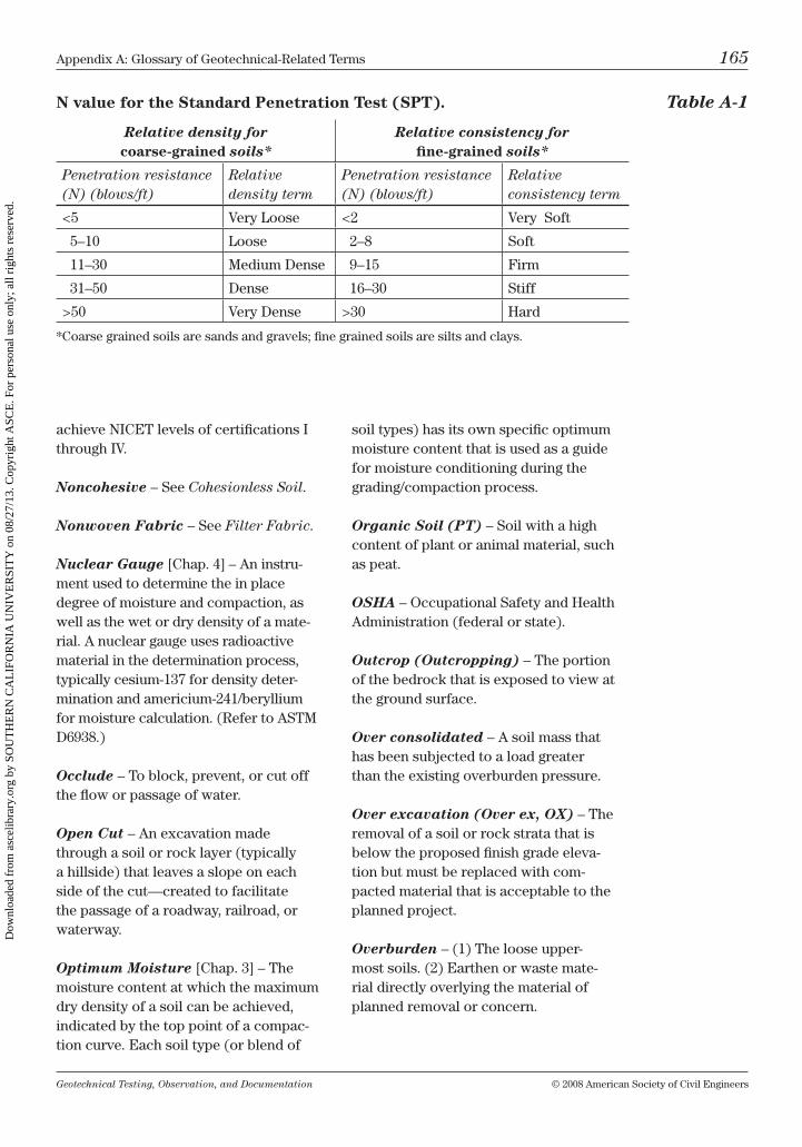
Geotechnical Testing, Observation, and Documentation © 2008 American Society of civil Engineers
Appendix A: Glossary of Geotechnical-related terms 165
achieve nicEt levels of certifications i through iv.
Noncohesive – See Cohesionless Soil.
Nonwoven Fabric – See Filter Fabric.
Nuclear Gauge [chap. 4] – An instru-ment used to determine the in place degree of moisture and compaction, as well as the wet or dry density of a mate-rial. A nuclear gauge uses radioactive material in the determination process, typically cesium-137 for density deter-mination and americium-241/beryllium for moisture calculation. (refer to AStm D6938.)
Occlude – to block, prevent, or cut off the flow or passage of water.
Open Cut – An excavation made through a soil or rock layer (typically a hillside) that leaves a slope on each side of the cut—created to facilitate the passage of a roadway, railroad, or waterway.
Optimum Moisture [chap. 3] – the moisture content at which the maximum dry density of a soil can be achieved, indicated by the top point of a compac-tion curve. Each soil type (or blend of
soil types) has its own specific optimum moisture content that is used as a guide for moisture conditioning during the grading/compaction process.
Organic Soil (PT) – Soil with a high content of plant or animal material, such as peat.
OSHA – occupational Safety and health Administration (federal or state).
Outcrop (Outcropping) – the portion of the bedrock that is exposed to view at the ground surface.
Over consolidated – A soil mass that has been subjected to a load greater than the existing overburden pressure.
Over excavation (Over ex, OX) – the removal of a soil or rock strata that is below the proposed finish grade eleva-tion but must be replaced with com-pacted material that is acceptable to the planned project.
Overburden – (1) the loose upper-most soils. (2) Earthen or waste mate-rial directly overlying the material of planned removal or concern.
N value for the Standard Penetration Test (SPT). Table A-1
Relative density for coarse-grained soils*
Relative consistency for fine-grained soils*
Penetration resistance (N) (blows/ft)
Relative density term
Penetration resistance (N) (blows/ft)
Relative consistency term
<5 very loose <2 very Soft
5–10 loose 2–8 Soft
11–30 medium Dense 9–15 Firm
31–50 Dense 16–30 Stiff
>50 very Dense >30 hard
*coarse grained soils are sands and gravels; fine grained soils are silts and clays.
Dow
nloa
ded
from
asc
elib
rary
.org
by
SOU
TH
ER
N C
AL
IFO
RN
IA U
NIV
ER
SIT
Y o
n 08
/27/
13. C
opyr
ight
ASC
E. F
or p
erso
nal u
se o
nly;
all
righ
ts r
eser
ved.
Geotechnical Testing, Observation, and Documentation © 2008 American Society of civil Engineers
166 Appendix A: Glossary of Geotechnical-related terms
Oversized Material – (1) boulder or rock fragments that exceed the maxi-mum diameter allowable in a soil or soil–rock fill as specified by the plans, specs, or geotechnical report. (2) mate-rial deemed untestable by the nuclear gauge and sand cone methods—because more than 30% of the material is larger than ¾ in. size—as limited by the maxi-mum density test (both AStm D1557 and D698 methods).
Packer – A device lowered into a bore-hole that automatically swells or can be controlled to expand at the correct time to produce a watertight seal against the sides of a borehole or casing.
Parent Material – material from which a soil has been derived.
Particle – A general term referring to any size individual grain, from a micro-scopic colloid to a huge rock.
Pass – one trip or movement across a designated area by a piece of excavation or compaction equipment.
Pavement Section (Structural Sec-tion, Section) – the combined thick-ness of asphalt, aggregate base, and sometimes aggregate subbase material that is designed and recommended by an engineer as a total roadway structure. the designed thickness of this pavement section is based on factors such as r value of subgrade soils, traffic volumes, and loads (traffic index, ti).
Pea Gravel – clean gravel with grain size of approximately 5 mm in diameter (#4 sieve).
Peat (PT) – A fibrous, highly organic soil, generally dark brown to black.
Pedology – the science that pertains to soil, including its nature, properties,
formation, functioning behavior, and response to use and management.
Peep Site – See Hand Level.
Penetration Resistance – See N Value.
Penetrometer – See Pocket Penetrometer.
Percent Compaction (Degree of Compaction) – the ratio (expressed as a percentage) of the dry density of a soil (as determined by a field density test) to the laboratory maximum dry density.
Percent of Consolidation – See Degree of Consolidation.
Percent Saturation – the ratio (expressed as a percentage) of the volume of water in a given soil mass to the total volume of the intergranular space (voids).
Perched Water Table – A water table (usually of limited area) maintained above the normal free water elevation by the presence of an intervening, rela-tively impermeable confining strata.
Percolation – the movement of gravi-tational water through permeable soil.
Percussion Drilling – A drilling method that uses a solid or hollow-stem auger to cut and crush rock with repeated blows.
Perforated Pipe (Perforated Drain Pipe) – A plastic pipe (typically Pvc) with two rows of holes (perforations) equally spaced along the bottom third of the pipe. Proper placement of the pipe is with the holes facing downward—thus allowing water to flow up into the pipe, while minimizing the migration of fines (sediment) through the holes. Drain pipe is typically surrounded by drain rock,
Dow
nloa
ded
from
asc
elib
rary
.org
by
SOU
TH
ER
N C
AL
IFO
RN
IA U
NIV
ER
SIT
Y o
n 08
/27/
13. C
opyr
ight
ASC
E. F
or p
erso
nal u
se o
nly;
all
righ
ts r
eser
ved.
Geotechnical Testing, Observation, and Documentation © 2008 American Society of civil Engineers
Appendix A: Glossary of Geotechnical-related terms 167
which is in turn enveloped with filter fabric.
Permafrost – Perennially frozen soil or ground that remains below freezing tem-perature for two or more years.
Permeability – the ease with which water will flow through soil or rock. For example; clean sand is a perme-able soil, whereas highly plastic clay is impermeable.
Permeability Test – A procedure often used to determine the water tightness of a soil or rock formation. it may be used prior to the construction of a dam, pond, or detention basin. the field test is per-formed by placing packer assemblies in a borehole to seal off successive strata or at specified intervals (typically every five feet). Water is injected into the bore-hole space between the packers with a high pressure pump. the volume of water lost in each rock, soil formation, or interval is a measure of permeability.
pH – the measure of acidity or alkalin-ity of a solution—or soil when damp-ened. the ph of pure water is 7; the higher the number, the more alkaline is the solution.
Piezometer – An instrument for mea-suring pressure head.
Pile (Friction or Bearing) – A struc-tural element that is driven, drilled, or otherwise introduced vertically into the soil or rock formation for structural sup-port. Support is provided by skin friction between the pile and soil (friction) and/or by end bearing of the pile tip on the lower stratum.
Piping (Migration) – the progressive washing away (migration) of soil parti-cles (generally low-cohesive to noncohe-sive material) within a mass caused by the percolation of water, leading to the
development of channels and the poten-tial collapse of the mass structure.
Pitcher Tube™ (Similar to Shelby Tube™) [chap. 2] – A thin walled steel tube, used to sample soil or soft rock from a borehole. Pitcher tube™ sam-pling is done from drill rigs equipped with rotary wash tools.
Plastic Limit (PL) [chap. 3] – (1) test: the water content of a soil at which it will just begin to crumble when rolled into a 1⁄8 -in. thread (AStm Standard test method D4318). (2) the water content corresponding to an arbitrary limit between the plastic and semisolid states of consistency of a soil.
Plasticity – the property of a soil that allows it to be deformed beyond the point of recovery without cracking or appreciable volume change.
Plasticity Index (PI) [chap. 3] – the numerical difference between the liquid limit and the plastic limit.
Plasticizer – A chemical additive that will increase the workable time (plastic-ity) of a cementitious mixture.
Pneumatic Tired Roller – A heavy roller with air filled rubber tires— typically used to compact cohesive soils and asphalt.
Pocket Penetrometer – A handheld piston-type device that when pushed into a soil (either in-place or into a soil in a sample tube) can give an indica-tion of the cohesive soil strength and consistency—read from 0 to 4.5 in.-ton per square foot (tsf). can be used to evaluate the side walls of excava-tions per oShA cohesive soil clas-sification (29 cFr Part 1926, Subpart P – Excavations).
Dow
nloa
ded
from
asc
elib
rary
.org
by
SOU
TH
ER
N C
AL
IFO
RN
IA U
NIV
ER
SIT
Y o
n 08
/27/
13. C
opyr
ight
ASC
E. F
or p
erso
nal u
se o
nly;
all
righ
ts r
eser
ved.
Geotechnical Testing, Observation, and Documentation © 2008 American Society of civil Engineers
168 Appendix A: Glossary of Geotechnical-related terms
Pore Pressure – Stress transmitted by pore water (water within the voids of a soil).
Porosity – (1) the ratio (expressed as a percentage) of the volume of voids in a given soil mass to the total volume of the soil mass. (2) indication of pore space or voids within a soil or rock mass.
Porous Soil – Soil with observable small voids, interstices, or holes. cohe-sive soils may appear “spongelike” because of holes from root decay, worm, or bug holes, etc. noncohesive soils are considered porous because of void space between particles and/or grains.
Portland Cement – cement that con-sists of the compounds silica, lime, and alumina.
Portland Cement Association (PCA) – Founded in 1916; represents concrete companies in the united States and canada. the PcA conducts market development, performs engineering research, provides education, and employs code specialists who work in the field to promote and protect con-crete interests in national building code organizations.
Post Tensioning – A method in which cables are placed into a slab area prior to pouring concrete, and then, after the concrete has cured, the cables are tightened—stressing (or tensioning) the concrete—creating a slab that will move as a more monolithic unit (floating slab).
Potato Dirt – A term used to describe earthen material that is easily worked (compacted or excavated).
Pre-grade Meeting (Pre-con Meet-ing) – An important meeting held prior to the beginning of the project detail-ing items such as estimated start and
completion dates (schedule), specifica-tions, plans, geotechnical recommenda-tions, safety, and introduction of project personnel.
Pre saturation – the moisture condi-tioning (above optimum moisture) of a pad and/or footing excavation prior to the pouring of concrete. Pre saturation is usually performed on expansive soils to reduce future swelling of the soil (as may be caused by seasonal rains or heavy landscape watering), which may cause concrete foundations to heave, crack, or separate.
Pressure Grouting (Mud Jacking) – A method of stabilizing or improving the density of a soil mass by injecting under pressure (to infill voids) a mixture of cement, soil, and water.
Pressure Testing – A method to test the permeability of a soil or rock forma-tion in which water or grout is pumped down hole under pressure. See Perme-ability Test.
Pre stressed Concrete – concrete that has been compressed to reduce or elimi-nate cracking or tensile forces.
Probe (Soil Probe, Hand Probe) [chap. 11] – A t shaped implement (approximately 3 ft in length) with a pointed end; used as a guide in check-ing backfill, footing bottoms, or other questionable backfill areas for density or consistency.
Proctor – Slang for maximum density test; originated from the original maxi-mum density test method proposed by r. r. Proctor in 1933.
Proof Roll – the use of heavy rubber tired equipment (such as a fully loaded water truck) driven over a road sub-grade or aggregate base to help deter-mine the stability of the surface.
Dow
nloa
ded
from
asc
elib
rary
.org
by
SOU
TH
ER
N C
AL
IFO
RN
IA U
NIV
ER
SIT
Y o
n 08
/27/
13. C
opyr
ight
ASC
E. F
or p
erso
nal u
se o
nly;
all
righ
ts r
eser
ved.
Geotechnical Testing, Observation, and Documentation © 2008 American Society of civil Engineers
Appendix A: Glossary of Geotechnical-related terms 169
Pumping – may be observed as a roll-ing motion in soils placed or compacted in an over optimum condition (too wet). these pumping soils may—during the compaction process—become rutted or indented by rubber tired equipment, usually leaving a bulging path in the soil parallel to the tire print. in a condition of widespread pumping, the soil surface may move in a slow wavelike action while compacting. Proof rolling is a good method in which to locate pump-ing soils.
Quicksand – A specific mixture of silt and fine sand in which the bearing capacity of the mass has been greatly reduced by its thorough saturation by water.
R Value (Resistance Value) – A test value resulting from a soil test in a hveem stabilometer, in which a short cylindrical sample prepared by kneading compaction is subjected to an axial load. the resultant horizontal pressure is measured, and the strength is expressed in terms of a resistance value (r). the r value is used in pavement design to help determine the thickness of the pave-ment section. A higher r value number indicates a generally more granular soil and a better rating for a road subgrade material.
Raveling – the loosening, falling, or breaking away of materials from a bank or slope face.
Rebar – A steel reinforcement bar.
Recovery (Percent Recovery) – the amount of soil or rock sample obtained from a borehole by use of any soil sam-pling device; may be expressed as the ratio of the sample length recovered to the sample length attempted.
Refusal – term used in exploratory drilling to describe the time when a drill
bit cannot proceed any further, or the point at which a sampling barrel or tube cannot be driven (or pushed) any further without damaging the sampler.
Relative Density – the ratio of the dif-ference of a cohesionless soil: (1) in its loosest state to any given void ratio or (2) between the void ratios in its loosest and densest states.
Retaining Wall [chap. 5] – A rein-forced wall designed to resist the lateral pressure produced by a potentially unstable soil or rock mass.
Rework – to recompact a portion of pre-viously compacted, but unaccepted, fill.
Rippability (Excavatability) [chap. 2] – the ease or difficulty with which removals or cuts can be made in rock or cemented soils.
Rippers – Steel shanks (tooth shaped attachments) that are placed on the rear of heavy equipment—such as blades and dozers—to help loosen (rip) rocky or cemented formations.
Ripping – (1) the process in which bedrock or hard cemented materials are broken up by a single shank (ripper tooth) of a dozer. (2) the act of scarify-ing the ground surface by the ripper teeth of a dozer or a blade in preparation for fill placement.
Rip Rap (Riprap) – broken rock (pri-marily cobble to boulder size) placed to protect embankments, cut slopes, shore-lines, etc., against erosion from running water or wave action. rip rap generally is angular and has a number of fractured faces, as well as having a high enough specific gravity to help hold the material into place during wave or flood action.
Dow
nloa
ded
from
asc
elib
rary
.org
by
SOU
TH
ER
N C
AL
IFO
RN
IA U
NIV
ER
SIT
Y o
n 08
/27/
13. C
opyr
ight
ASC
E. F
or p
erso
nal u
se o
nly;
all
righ
ts r
eser
ved.
Geotechnical Testing, Observation, and Documentation © 2008 American Society of civil Engineers
170 Appendix A: Glossary of Geotechnical-related terms
Rock – naturally formed solid mineral matter, occurring in large masses or fragments.
Rock Fill [chap. 5] – rocks, cobbles, or boulders blended with a soil matrix during placement with ample amounts of water—in such a manner as to limit voids and nesting, allowing for a homo-geneous, well compacted fill.
Rock Mechanics – (1) the theoretical and applied science of the mechanical behavior of rock, and the application of engineering practices in dealing with rock problems. (2) People who are expe-rienced and specialize in the repair of broken rocks.
Rockery Wall [chap. 5] – A retain-ing wall composed of angular, durable, dense rocks placed according to engineered design—typically inclined into slope (batter) of 1:6, with a fabric-encased rock drain placed along the inside of the wall.
Roller Compacted Concrete (RCC) – cement and soil, usually mixed on site or nearby, placed and compacted in a near optimum/low slump condition.
Rotary Wash Drilling – A drilling rig using rotary tools and any type of circu-lating fluid (such as drilling mud) with which to drill boreholes.
Rough Grade – the elevation to which a site is graded before “blue tops” are placed—typically within a few tenths or less of finish grade elevation.
Rough Grading – the early stages of a grading project when streets, pads, park-ing areas, etc., are graded to within a few tenths of a foot to finish grade.
Rupture Plane – Plane or surface in which failure or substantial movement has occurred.
Sample Grabber (Sample Catcher) – A device that is placed inside a drive sampler between the drive shoe and sample barrel—used to help hold a noncohesive soil in the sampler during sample recovery.
Sand – Particles of rock ranging in diameter between the #4 sieve (4.75 mm) and the #200 sieve (0.075 mm). col-lectively, the sand grains are generally noncohesive and permeable. Sand is between gravel and silt size.
Sand Boil – the upward movement (ejection) of sand and water caused by piping.
Sand Cone [chap. 4] – A device used to determine in place density of soil; the sand cone is composed of three main parts: the cone—funnel shaped with a valve to control the flow of sand; the jar—a plastic container to hold sand (screws onto the cone); and the plate— a guide for digging and seating the cone over the hole. (refer to AStm D1556).
Sandstone – A sedimentary rock com-posed of cemented sand grains.
Scarify (Rip) – the act of loosening the existing surface material (usually by ripper teeth on a dozer or blade) to mix, blend, or prepare for fill placement.
Scarp – A steep, near vertical slope along the top or edge of a plateau, mesa, terrace, bench, landslide, slump, or fault.
Scraper – A large mobile truck-type transport—used for the hauling and transporting of earthen loads—that has a movable cutting edge and is able to discharge its load by sliding a movable wall within its bed.
Sedimentary Rock – A rock formed by the accumulation of mineral grains and rock fragments by erosion processes;
Dow
nloa
ded
from
asc
elib
rary
.org
by
SOU
TH
ER
N C
AL
IFO
RN
IA U
NIV
ER
SIT
Y o
n 08
/27/
13. C
opyr
ight
ASC
E. F
or p
erso
nal u
se o
nly;
all
righ
ts r
eser
ved.
Geotechnical Testing, Observation, and Documentation © 2008 American Society of civil Engineers
Appendix A: Glossary of Geotechnical-related terms 171
may be cemented by agents such as silica, carbonates, or oxides.
Seepage – the slow movement of gravi-tational water through soil or soft rock.
Segregation – the separation of coarse and fine material, typically resulting from actions of water or motion.
Seismic Refraction Survey [chap. 2] – one method involves transmitting seismic waves through rock and soil strata to help determine the hardness (excavatability/rippability) of an area of proposed cut.
Seismic Wave [chap. 2] – A wave, generated by an earthquake, explosion, or a hard impact, that travels through the earth; seismic waves may vary in velocity depending on the intensity of the source and the strata through which they are traveling.
Shaking Test [chap. 1] – A method used to determine the dilatancy of a soil.
Shale – A sedimentary rock composed primarily of silt and clay. it tends to break and fracture in thin layers.
Shear Failure – the parallel adverse movement along a plane of contact within a soil mass—of sufficient magni-tude to seriously damage or destroy the structure of the mass.
Shear Key – A large trench (keyway) excavated through a creep, slide, or potentially unstable hillside to buttress the disturbed zones—but not placed at the disturbance base—then backfilled with compacted material to prevent slid-ing at the point of extra fill load.
Shear Strength – the maximum resis-tance of soil to shear stress.
Shear Stress – the action resulting from applied forces that tends to cause soil masses to slide adversely in a direc-tion parallel to their plane of contact.
Sheepsfoot Roller – A steel drum roller with pads (feet) welded to its surface, used to compact soil.
Shelby Tube™ (Similar to Pitcher Tube™) – A thin walled steel tube used for sampling soil or soft rock.
Shoring – Wooden or metal braces placed against the side walls of a trench or other excavations for safety; used to help prevent the walls from sloughing or caving in.
Shotcrete – A prepared wet mixture of concrete that is pumped through a hose to a nozzle, at which time compressed air is introduced to impel the mixture onto the receiving structure. Shotcrete has a high heat resistance and adheres well to concrete, brick, tile, stone, and steel. Shotcrete may be sprayed over reinforced soil surfaces to help retain slopes or vertical cuts.
Sieve – A wire (or nylon) mesh with specific size openings used to separate soil grain sizes. the following are some standard u.S. and equivalent metric sieve sizes.3 in. = 75 mm2 in. = 50 mm1½ in. = 37.5 mm¾ in. = 19 mm1⁄8 in. = 9.5 mm#4 = 4.75 mm#8 = 2.36 mm#10 = 2 mm#16 = 1.18 mm#20 = 850 µm#30 = 600 µm#40 = 425 µm#50 = 300 µm#60 = 250 µm#100 = 150 µm#140 = 106 µm#200 = 75 µm#400 = 38 µm
Dow
nloa
ded
from
asc
elib
rary
.org
by
SOU
TH
ER
N C
AL
IFO
RN
IA U
NIV
ER
SIT
Y o
n 08
/27/
13. C
opyr
ight
ASC
E. F
or p
erso
nal u
se o
nly;
all
righ
ts r
eser
ved.
Geotechnical Testing, Observation, and Documentation © 2008 American Society of civil Engineers
172 Appendix A: Glossary of Geotechnical-related terms
(Also refer to AStm E–11 for sieve standards.)
Sieve Analysis – See Grain Size Analysis.
Silt – material that is smaller than sand (#200 sieve; 75 µm) but has a particle diameter larger than clay (5 µm). Silt will plot below the “A” line on the Plas-ticity chart, as defined by the liquid and plastic limits test.
Siltation – the process by which silt, clay, and fine sand that is transported by rivers and streams is deposited along the way.
Site – Any parcel of land in which grading or construction is planned or performed.
Skin Friction – the frictional resis-tance developed at points of contact between soil or rock and a structure.
Slab Foundation – A concrete foundation—which may or may not be supported by footings—that has been poured directly onto a prepared sur-face, with no crawl space or basement beneath it.
Slaking – the act of breaking apart or sloughing off when a hardened soil has been immersed in water.
Slickensided – A secondary structural feature in bedrock produced by move-ments along the walls of joints; slick and glossy in appearance.
Slide – See Landslide.
Slide Plane – A plane of shear failure, roughly parallel to the slope face.
Slope – An inclined ground surface. the inclination can be expressed as the hori-zontal distance to the vertical distance;
for example, 2 ft horizontal to 1 ft verti-cal may be expressed as a 2:1 slope. See Inclination.
Slope Angle – See Inclination.
Slope Stability – (1) the resistance of a slope to mass failure. (2) to but-tress, brace, or protect a slope in such a manner as to stabilize it from massive or partial failure.
Slope Wash – Soil and rock transported downhill by the actions of water and gravity.
Sloughing – the raveling or breaking off of material from any sloped or verti-cal face.
Slump – (1) A downward movement or slipping of a mass of earth material, characterized by a rotational motion. often recognized by a scarp at the top point of slipping and a bulge toward the bottom of the movement. (2) A measure-ment (performed by a slump test) of the workability (stiffness) of freshly batched concrete; slump is a general indicator of the amount of water added to the mix and/or the time since the concrete was batched.
Slump Test – A measurement of the workability (stiffness) of freshly batched concrete performed by placing the con-crete mix (in three layers) into a metal cone (with the small opening upward), rodding each layer 25 times, then slowly removing the cone and measuring the amount of lowering (slump) of the mate-rial (measured from the top of the cone to the top of the remaining material). (refer to AStm c143.)
Soil – Sediments and other accumula-tions of solid particles produced by chemical and physical disintegration of rocks; may or may not contain organic matter.
Dow
nloa
ded
from
asc
elib
rary
.org
by
SOU
TH
ER
N C
AL
IFO
RN
IA U
NIV
ER
SIT
Y o
n 08
/27/
13. C
opyr
ight
ASC
E. F
or p
erso
nal u
se o
nly;
all
righ
ts r
eser
ved.
Geotechnical Testing, Observation, and Documentation © 2008 American Society of civil Engineers
Appendix A: Glossary of Geotechnical-related terms 173
Soil Engineer (Geotechnical Engi-neer) – An engineer experienced in the practical applications of soil science and civil engineering.
Soil Horizon – one of the layers of the soil profile, distinguished principally by its texture, color, structure, and chemi-cal and mineral composition.
Soil Nailing – A method of reinforcing a potentially unstable soil or rock mass by inserting steel rods into predrilled holes, then grouting the rods into place, thus creating a more stable and solid monolithic mass.
Soil Profile – A vertical section of a soil mass showing the geologic nature (and often engineering properties) of various layers.
Soil Stabilization – A chemical or mechanical treatment designed to increase or maintain the stability of a soil mass or otherwise improve its engi-neering properties.
Soil Technician (Geotechnical Technician) – A person trained to test, observe, and document the process of soil manipulation for construction purposes.
Soil Technology – the application of soil engineering and geology for the use of controlling and predicting the action of soil and rock for structural purposes.
Specific Gravity (of Solids) – the ratio of the weight in air of a given volume of solids at a known tempera-ture to the weight in air of an equal volume of distilled water at a known temperature.
Spit Spoon – Slang for split barrel or SPt sampler.
Splash Block – A block of concrete placed beneath a downspout (drain outlet)—used to control erosion by allowing the water to discharge onto the concrete block, not the ground.
Spoil – material that is excess or unwanted, typically disposed of off site.
Spread – A term used by a grading con-tractor to describe the total heavy equip-ment (dozers, blades, scrapers, etc.) that will be or is being used on a grading project.
Spring – A location at the ground sur-face in which water seeps out more or less continually from the water table.
SPT – See Standard Penetration Test.
Stabilization Fabric – A geogrid or woven geotextile fabric that, when placed in a specific configuration (and usually overlain by a predominantly gravel mixture), will act as a stabiliz-ing blanket over unstable soils such as peat, marshland, soft saturated clays, or pumping soils.
Stabilization Fill – An engineered fill placed to support or protect a natural slope against massive failure or the forces of erosion.
Standard Penetration Test (SPT) [chap. 2] – A down hole sampling method used in determining the relative consistency or density of a soil forma-tion by obtaining a penetration resis-tance value (n value). the procedure is performed by lowering a split barrel sampler into a borehole, and then count-ing the number of 30-in. drops it takes a free falling 140-lb weight (hammer) to drive the sampler a depth of 1 ft.
Standard Proctor – the standard Proctor was proposed in 1933 by r. r. Proctor and was used as the standard
Dow
nloa
ded
from
asc
elib
rary
.org
by
SOU
TH
ER
N C
AL
IFO
RN
IA U
NIV
ER
SIT
Y o
n 08
/27/
13. C
opyr
ight
ASC
E. F
or p
erso
nal u
se o
nly;
all
righ
ts r
eser
ved.
Geotechnical Testing, Observation, and Documentation © 2008 American Society of civil Engineers
174 Appendix A: Glossary of Geotechnical-related terms
maximum density test (AStm D698) until being updated by the modified Proctor (AStm D1557). in the standard Proctor test a 5.5-lb hammer with a 12-in. drop and three layers are used; the modified Proctor uses a heavier (10-lb) hammer, a longer drop (18 in.), and five equal layers placed in either a 4- or 6-in.-diameter mold.
Static Compaction – the densification of a soil mass by loading it with weight only, not by impact or vibration.
Sticky Limit – the lowest moisture content at which a soil will stick to a metal blade drawn across the soil sample.
Stockpile – A quantity of material temporarily placed in an out of the way location until the pile can be removed for intended use.
Stone – A small piece of rock of any shape, from gravel to cobble size.
Strain – the change in length, per unit length, in a given direction.
Stratification – (1) A parallel struc-ture resulting from the deposition of sediment beds, layers, or strata. (2) the arrangement of rocks in beds, layers, and strata.
Stratum (Strata) – A single layer of homogeneous or gradational lithology deposited parallel to the original dip of the formation. it is separated from adja-cent strata or cross strata by surfaces of erosion, nondeposition, or abrupt changes in character.
Stress – the force per unit area acting within the soil mass.
Strike – the geologic direction of a line created by a plane where it intersects the horizontal.
Subbase – A layer of material used in a pavement system between the subgrade and basecourse material.
Subdrain – A drainage system placed beneath the surface to drain subsurface water. it typically consists of filter mate-rial and/or a specified type and size of drain pipe.
Subgrade – the layer of soil that is compacted immediately beneath the subbase or aggregate basecourse in a roadway section.
Subgrade Surface – See Finished Subgrade.
Subsidence – the sinking or lowering of a part of the earth’s crust.
Subsoil – Soil below a subgrade or existing fill.
Surcharge – (1) A load behind a wall or structure that is applying a force or load against that structure. (2) A load applied to a soil in the laboratory or in the field, and then monitored for consolidation or settlement.
Surficial – (1) the unmoved surface of the earth. (2) upper, near surface material.
Survey Stake – See Lath.
Swale – A depression in generally level ground. A swale may be developed by natural runoff water or may have anthro-pogenic origin, such as a drainage used to collect runoff and direct it away from buildings or other structures.
Swell – An increase in volume resulting from the absorption of water into the intergranular pore space. many types of clay have a tendency to swell when wet.
Dow
nloa
ded
from
asc
elib
rary
.org
by
SOU
TH
ER
N C
AL
IFO
RN
IA U
NIV
ER
SIT
Y o
n 08
/27/
13. C
opyr
ight
ASC
E. F
or p
erso
nal u
se o
nly;
all
righ
ts r
eser
ved.
Geotechnical Testing, Observation, and Documentation © 2008 American Society of civil Engineers
Appendix A: Glossary of Geotechnical-related terms 175
SWPPP (Storm Water Pollution Prevention Plan) – A plan to help limit the runoff and uncontrolled drainage of storm water, sediments, and other pol-lutants that may result from construc-tion activities. An SWPPP plan for con-struction projects must be developed in compliance with the u.S. Environmental Protection Agency requirements con-tained in the national Pollution Dis-charge Elimination System (nPDES) as enacted in the clean Water Act (cWA) and requirements of other governing agencies.
Tailings – (1) material that has been dropped, spread, or inadvertently placed without the benefit of adequate moisture conditioning or compaction—often rem-nant material from haul roads. (2) the waste material remaining after ore has been processed in a mining operation.
Talus – Angular rock debris accu-mulated at the toe of a slope or base of a cliff, produced by the action of weathering.
Tamping – the act of compacting soil by use of weighted tools or machinery.
Tensile Strength – the load per unit area at which an elongated or cylindrical specimen will fail in a pull (tension) test.
Terrace – A relatively level step con-structed in the face of a slope, used for maintenance purposes or drainage.
Thermo osmosis – the process by which water is caused to flow through the interstices of a soil mass owing to dif-ferences in temperature within the mass.
Thrust Block – See Kicker.
Tie backs – Engineer-designed—drilled and often grouted into place—anchors that are fastened into bedrock or soil.
Toe – the point at which the bottom of a natural, fill, or cut slope contacts with a relatively level or horizontal ground surface.
Topography – the surface physi-cal features of the land—its relief and contours.
Topsoil – Surface soil, usually contain-ing organic matter.
Track Walk – A process in which gen-erally shallow compaction is achieved by track mounted equipment (typically a dozer) by repeatedly passing over an area of fill.
Traffic Index (TI) – An index of the expected level of traffic loading on a street or highway.
Transition Lot – (1) A lot in which a portion is to be cut (or excavated) and a portion is to be filled (or raised) to reach finished pad grade. (2) A lot in which a daylight line passes through.
Tremie – (1) A hose or metal pipe of variable length used to pour concrete under water. (2) to place concrete through a pipe in a manner such that the concrete reaches the pour zone without mixing with water or segregating due to extensive free fall.
Trench Log [chap. 2] – A writ-ten record of subsurface conditions observed during the excavation of an exploratory trench, including descrip-tions of soil, rock, strata, moisture, and orientation of the trench.
Triaxial Strength Test – A labora-tory test in which a saturated cylindrical sample of soil is encased in an imper-vious membrane, then subjected to a confining pressure and cyclic stress and loaded axially to failure. often used to simulate undrained field conditions that
Dow
nloa
ded
from
asc
elib
rary
.org
by
SOU
TH
ER
N C
AL
IFO
RN
IA U
NIV
ER
SIT
Y o
n 08
/27/
13. C
opyr
ight
ASC
E. F
or p
erso
nal u
se o
nly;
all
righ
ts r
eser
ved.
Geotechnical Testing, Observation, and Documentation © 2008 American Society of civil Engineers
176 Appendix A: Glossary of Geotechnical-related terms
may arise during earthquakes or other cyclic loading. (refer to AStm D5311).
Unconfined Compressive Strength – the load per unit area at which an unconfined cylindrical sample will fail in a simple compression test. (refer to AStm D7012.)
Unconformity – A lack of continuity between two units of rock in contact, indicating an apparent gap in geo-logic record, the gap being a period of erosion.
Underconsolidated Soil Deposit – A deposit that has not been fully con-solidated under the existing overburden pressure.
Underpinning – A footing introduced beneath an existing footing, for the purpose of transferring the foundation load to a lower depth onto more suitable material.
Undisturbed Sample (Relatively Undisturbed Sample) – A soil or rock sample that has been obtained by meth-ods in which every precaution has been taken to recover the sample in its natu-ral or in situ state.
Unified Soil Classification System (USCS) – A widely used system for identifying and classifying soils for engineering purposes. the system was developed by Dr. Arthur casagrande in the early 1940s, and then was adopted for use by the Army corps of Engineers in 1952. it has since been standardized by AStm and others.
Uniform Building Code (UBC) – Standard specifications for safe con-struction; the ubc was published in book form and updated every four years. the ubc was discontinued with the 1997 edition. the international building
code (ibc) is now published as the national comprehensive building and safety code standards.
Unit Weight of Water – the weight per unit volume of water—normally equal to 62.4 lb/ft3 or 1 g/cm3.
Uplift – (1) the hydrostatic force of water exerted on or underneath a struc-ture, tending to cause displacement of the structure. (2) the upward movement of the earth’s crust.
Utility Trench – A trench excavated for the placement of utilities, such as electrical, sewer, and gas.
V Ditch – A v-shaped trench dug into the ground to collect and transport water, often placed along a roadway, across a bench in a slope, or tied into a low area to allow it to drain.
Vane Shear Test – An in place shear test used in cohesive soils in which a rod with thin radial vanes at the end is forced into the soil and then rotated; the resistance to rotation of the rod is then measured—giving an approximate shear strength value.
Vapor Barrier – See Moisture Barrier.
Varved Soil – Alternating layers of silt (or fine sand) and clay formed by varia-tions in sedimentation; often exhibits contrasting colors when dried.
Vibratory Roller – A self-propelled flat steel drum or sheepsfoot roller that vibrates; the amplitude and frequency of the vibration can be adjusted on many rollers. vibratory sheepsfoot-type rollers work well for compacting noncohesive soils, whereas vibratory flat drum roll-ers compact aggregate base and asphalt well.
Dow
nloa
ded
from
asc
elib
rary
.org
by
SOU
TH
ER
N C
AL
IFO
RN
IA U
NIV
ER
SIT
Y o
n 08
/27/
13. C
opyr
ight
ASC
E. F
or p
erso
nal u
se o
nly;
all
righ
ts r
eser
ved.
Geotechnical Testing, Observation, and Documentation © 2008 American Society of civil Engineers
Appendix A: Glossary of Geotechnical-related terms 177
Viscosity – the property of a fluid to resist internal flow.
Void – the space in a soil mass not occupied by solid mineral matter; the space (interstice) between soil particles. this space may be occupied by air, water, or any other gas or liquid.
Void Ratio – the ratio of the volume of void space to the volume of solid par-ticles in a given soil mass.
Volcanic Rock – See Igneous Rock.
Water Content – the ratio of the weight of water contained within the pore space of a rock or soil sample to the dry solid weight of the sample—expressed as a percentage.
Water Table – the upper limit or sur-face of the saturated groundwater zone.
Weathered – A term used to describe rock that has been partially decomposed or disintegrated by the forces of nature over a period of time, by such actions as wind, water, ice, and chemical reactions.
Windrow – A long row of soil or other material formed by a blade or other grading equipment.
Woven Fabric – A geotextile fabric that has been strengthened by weaving the material together—allowing the fabric to have both stabilization and filtering properties.
Young’s Modulus (Elastic Modulus) – the ratio of the increase of stress on a test specimen to the resulting increase in strain—while under constant trans-verse stress—limited to materials that have a linear stress–strain relationship over the range of loading.
Zero Air Voids Curve (ZAV Curve) [chap. 3] – (1) the curve drawn on the maximum density test graph to indicate the specific gravity and saturation point of a given material, used as a guide in plotting the maximum density curve. (2) the curve showing the zero air voids unit weight as a function of the water content.
Zone of Saturation – the area below the water table in which all pore spaces are completely filled with water—known as groundwater.
Dow
nloa
ded
from
asc
elib
rary
.org
by
SOU
TH
ER
N C
AL
IFO
RN
IA U
NIV
ER
SIT
Y o
n 08
/27/
13. C
opyr
ight
ASC
E. F
or p
erso
nal u
se o
nly;
all
righ
ts r
eser
ved.

This page intentionally left blank
Dow
nloa
ded
from
asc
elib
rary
.org
by
SOU
TH
ER
N C
AL
IFO
RN
IA U
NIV
ER
SIT
Y o
n 08
/27/
13. C
opyr
ight
ASC
E. F
or p
erso
nal u
se o
nly;
all
righ
ts r
eser
ved.

Geotechnical Testing, Observation, and Documentation © 2008 American Society of civil Engineers 179
Appendix
bAnswer Keys
chapter 1 Questions and Answers
1. Porosity of a soil may indicate that the soil is:A) “Well graded”b) Engineered fillc)* A natural formation
2. Sand particles will not pass what size sieve?A)* #200 (0.075 mm)b) #4 (4.75 mm)c) #100 (1.50 mm)
3. A soil composed of 65% sand, 30% silt, and 5% clay could best be described as an:A) Scb)* Smc) mlD) none of the above
4. A soil composed of 40% sand, 30% clay, and 30% silt could best be described as an:A) cl/mlb)* Sc/Smc) Sm/cl
5. Which of the following are good indicators that a soil is more clayey than silty?A) light in color and porousb) low dry strength and feels soft when wetc)* high dry strength and no dilatancy reactionD) none of the above
Dow
nloa
ded
from
asc
elib
rary
.org
by
SOU
TH
ER
N C
AL
IFO
RN
IA U
NIV
ER
SIT
Y o
n 08
/27/
13. C
opyr
ight
ASC
E. F
or p
erso
nal u
se o
nly;
all
righ
ts r
eser
ved.
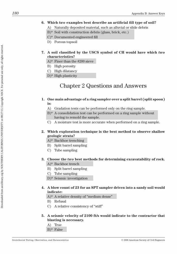
Geotechnical Testing, Observation, and Documentation © 2008 American Society of civil Engineers
180 Appendix b: Answer keys
6. Which two examples best describe an artificial fill type of soil?A) naturally deposited material, such as alluvial or slide debrisb)* Soil with construction debris (glass, brick, etc.)c)* Documented engineered fillD) Porous topsoil
7. A soil classified by the USCS symbol of CH would have which two characteristics?A)* Finer than the #200 sieveb) high porosityc) high dilatancyD)* high plasticity
chapter 2 Questions and Answers
1. One main advantage of a ring sampler over a split barrel (split spoon) is:A) Gradation tests can be performed only on the ring sample.b)* A consolidation test can be performed on a ring sample without
having to remold the sample.c) A moisture test is more accurate when performed on a ring sample.
2. Which exploration technique is the best method to observe shallow geologic strata?A)* backhoe trenchingb) Split barrel samplingc) tube sampling
3. Choose the two best methods for determining excavatability of rock.A)* backhoe trenchb) Split barrel samplingc) tube samplingD)* Seismic investigation
4. A blow count of 23 for an SPT sampler driven into a sandy soil would indicate:A)* A relative density of “medium dense”b) refusalc) A relative consistency of “stiff”
5. A seismic velocity of 2100 ft/s would indicate to the contractor that blasting is necessary.A) trueb)* False
Dow
nloa
ded
from
asc
elib
rary
.org
by
SOU
TH
ER
N C
AL
IFO
RN
IA U
NIV
ER
SIT
Y o
n 08
/27/
13. C
opyr
ight
ASC
E. F
or p
erso
nal u
se o
nly;
all
righ
ts r
eser
ved.
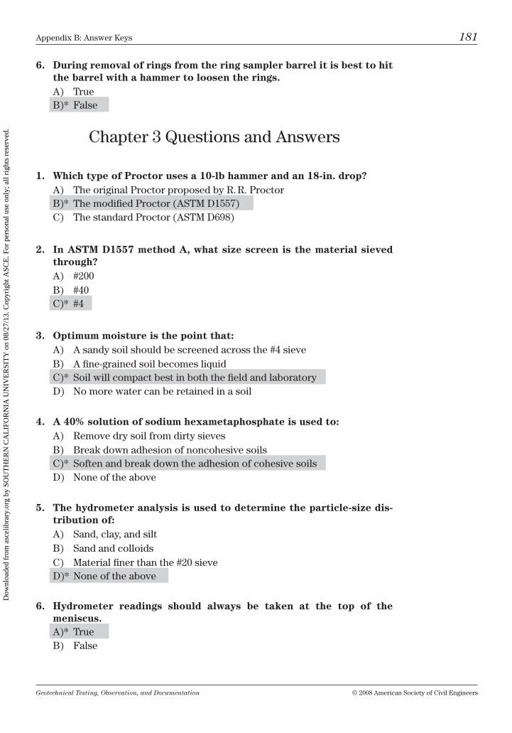
Geotechnical Testing, Observation, and Documentation © 2008 American Society of civil Engineers
Appendix b: Answer keys 181
6. During removal of rings from the ring sampler barrel it is best to hit the barrel with a hammer to loosen the rings.A) trueb)* False
chapter 3 Questions and Answers
1. Which type of Proctor uses a 10-lb hammer and an 18-in. drop?A) the original Proctor proposed by r. r. Proctorb)* the modified Proctor (AStm D1557)c) the standard Proctor (AStm D698)
2. In ASTM D1557 method A, what size screen is the material sieved through?A) #200b) #40c)* #4
3. Optimum moisture is the point that:A) A sandy soil should be screened across the #4 sieveb) A fine-grained soil becomes liquidc)* Soil will compact best in both the field and laboratoryD) no more water can be retained in a soil
4. A 40% solution of sodium hexametaphosphate is used to:A) remove dry soil from dirty sievesb) break down adhesion of noncohesive soilsc)* Soften and break down the adhesion of cohesive soilsD) none of the above
5. The hydrometer analysis is used to determine the particle-size dis-tribution of:A) Sand, clay, and siltb) Sand and colloidsc) material finer than the #20 sieveD)* none of the above
6. Hydrometer readings should always be taken at the top of the meniscus.A)* trueb) False
Dow
nloa
ded
from
asc
elib
rary
.org
by
SOU
TH
ER
N C
AL
IFO
RN
IA U
NIV
ER
SIT
Y o
n 08
/27/
13. C
opyr
ight
ASC
E. F
or p
erso
nal u
se o
nly;
all
righ
ts r
eser
ved.
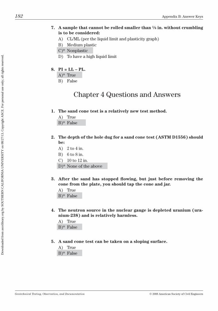
Geotechnical Testing, Observation, and Documentation © 2008 American Society of civil Engineers
182 Appendix b: Answer keys
7. A sample that cannot be rolled smaller than 1⁄8 in. without crumbling is to be considered:A) cl/ml (per the liquid limit and plasticity graph)b) medium plasticc)* nonplasticD) to have a high liquid limit
8. PI = LL – PL.A)* trueb) False
chapter 4 Questions and Answers
1. The sand cone test is a relatively new test method.A) trueb)* False
2. The depth of the hole dug for a sand cone test (ASTM D1556) should be:A) 2 to 4 in.b) 6 to 8 in.c) 10 to 12 in.D)* none of the above
3. After the sand has stopped flowing, but just before removing the cone from the plate, you should tap the cone and jar.A) trueb)* False
4. The neutron source in the nuclear gauge is depleted uranium (ura-nium-238) and is relatively harmless.A) trueb)* False
5. A sand cone test can be taken on a sloping surface.A) trueb)* False
Dow
nloa
ded
from
asc
elib
rary
.org
by
SOU
TH
ER
N C
AL
IFO
RN
IA U
NIV
ER
SIT
Y o
n 08
/27/
13. C
opyr
ight
ASC
E. F
or p
erso
nal u
se o
nly;
all
righ
ts r
eser
ved.
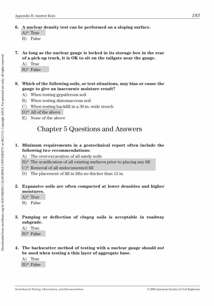
Geotechnical Testing, Observation, and Documentation © 2008 American Society of civil Engineers
Appendix b: Answer keys 183
6. A nuclear density test can be performed on a sloping surface.A)* trueb) False
7. As long as the nuclear gauge is locked in its storage box in the rear of a pick-up truck, it is OK to sit on the tailgate near the gauge.A) trueb)* False
8. Which of the following soils, or test situations, may bias or cause the gauge to give an inaccurate moisture result?A) When testing gypsiferous soilb) When testing diatomaceous soilc) When testing backfill in a 30-in.-wide trenchD)* All of the aboveE) none of the above
chapter 5 Questions and Answers
1. Minimum requirements in a geotechnical report often include the following two recommendations:A) the over-excavation of all sandy soilsb)* the scarification of all existing surfaces prior to placing any fillc)* removal of all undocumented fillD) the placement of fill in lifts no thicker than 12 in.
2. Expansive soils are often compacted at lower densities and higher moistures.A)* trueb) False
3. Pumping or deflection of clayey soils is acceptable in roadway subgrade.A) trueb)* False
4. The backscatter method of testing with a nuclear gauge should not be used when testing a thin layer of aggregate base.A) trueb)* False
Dow
nloa
ded
from
asc
elib
rary
.org
by
SOU
TH
ER
N C
AL
IFO
RN
IA U
NIV
ER
SIT
Y o
n 08
/27/
13. C
opyr
ight
ASC
E. F
or p
erso
nal u
se o
nly;
all
righ
ts r
eser
ved.
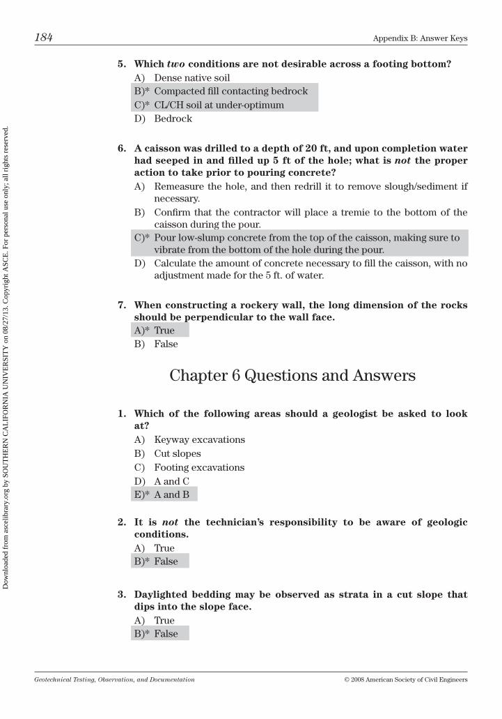
Geotechnical Testing, Observation, and Documentation © 2008 American Society of civil Engineers
184 Appendix b: Answer keys
5. Which two conditions are not desirable across a footing bottom?A) Dense native soilb)* compacted fill contacting bedrockc)* cl/ch soil at under-optimumD) bedrock
6. A caisson was drilled to a depth of 20 ft, and upon completion water had seeped in and filled up 5 ft of the hole; what is not the proper action to take prior to pouring concrete?A) remeasure the hole, and then redrill it to remove slough/sediment if
necessary.b) confirm that the contractor will place a tremie to the bottom of the
caisson during the pour.c)* Pour low-slump concrete from the top of the caisson, making sure to
vibrate from the bottom of the hole during the pour.D) calculate the amount of concrete necessary to fill the caisson, with no
adjustment made for the 5 ft. of water.
7. When constructing a rockery wall, the long dimension of the rocks should be perpendicular to the wall face.A)* trueb) False
chapter 6 Questions and Answers
1. Which of the following areas should a geologist be asked to look at?A) keyway excavationsb) cut slopesc) Footing excavationsD) A and cE)* A and b
2. It is not the technician’s responsibility to be aware of geologic conditions.A) trueb)* False
3. Daylighted bedding may be observed as strata in a cut slope that dips into the slope face.A) trueb)* False
Dow
nloa
ded
from
asc
elib
rary
.org
by
SOU
TH
ER
N C
AL
IFO
RN
IA U
NIV
ER
SIT
Y o
n 08
/27/
13. C
opyr
ight
ASC
E. F
or p
erso
nal u
se o
nly;
all
righ
ts r
eser
ved.
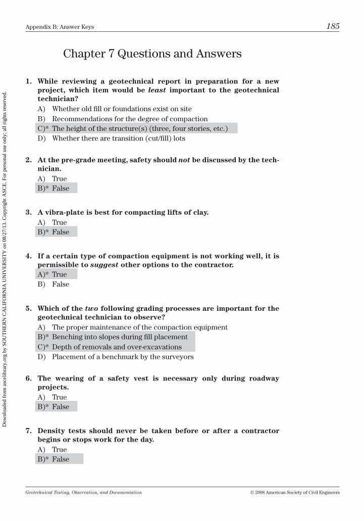
Geotechnical Testing, Observation, and Documentation © 2008 American Society of civil Engineers
Appendix b: Answer keys 185
chapter 7 Questions and Answers
1. While reviewing a geotechnical report in preparation for a new project, which item would be least important to the geotechnical technician?A) Whether old fill or foundations exist on siteb) recommendations for the degree of compactionc)* the height of the structure(s) (three, four stories, etc.)D) Whether there are transition (cut/fill) lots
2. At the pre-grade meeting, safety should not be discussed by the tech-nician.A) trueb)* False
3. A vibra-plate is best for compacting lifts of clay.A) trueb)* False
4. If a certain type of compaction equipment is not working well, it is permissible to suggest other options to the contractor.A)* trueb) False
5. Which of the two following grading processes are important for the geotechnical technician to observe?A) the proper maintenance of the compaction equipmentb)* benching into slopes during fill placementc)* Depth of removals and over-excavationsD) Placement of a benchmark by the surveyors
6. The wearing of a safety vest is necessary only during roadway projects.A) trueb)* False
7. Density tests should never be taken before or after a contractor begins or stops work for the day.A) trueb)* False
Dow
nloa
ded
from
asc
elib
rary
.org
by
SOU
TH
ER
N C
AL
IFO
RN
IA U
NIV
ER
SIT
Y o
n 08
/27/
13. C
opyr
ight
ASC
E. F
or p
erso
nal u
se o
nly;
all
righ
ts r
eser
ved.
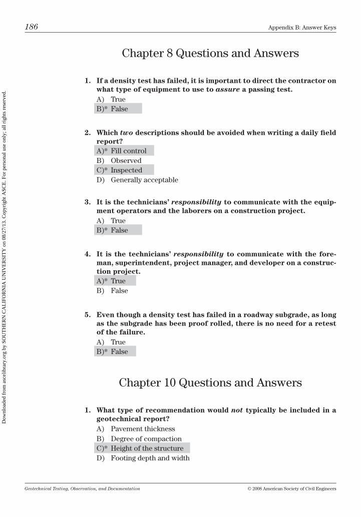
Geotechnical Testing, Observation, and Documentation © 2008 American Society of civil Engineers
186 Appendix b: Answer keys
chapter 8 Questions and Answers
1. If a density test has failed, it is important to direct the contractor on what type of equipment to use to assure a passing test.A) trueb)* False
2. Which two descriptions should be avoided when writing a daily field report?A)* Fill controlb) observedc)* inspectedD) Generally acceptable
3. It is the technicians’ responsibility to communicate with the equip-ment operators and the laborers on a construction project.A) trueb)* False
4. It is the technicians’ responsibility to communicate with the fore-man, superintendent, project manager, and developer on a construc-tion project.A)* trueb) False
5. Even though a density test has failed in a roadway subgrade, as long as the subgrade has been proof rolled, there is no need for a retest of the failure.A) trueb)* False
chapter 10 Questions and Answers
1. What type of recommendation would not typically be included in a geotechnical report?A) Pavement thicknessb) Degree of compactionc)* height of the structureD) Footing depth and width
Dow
nloa
ded
from
asc
elib
rary
.org
by
SOU
TH
ER
N C
AL
IFO
RN
IA U
NIV
ER
SIT
Y o
n 08
/27/
13. C
opyr
ight
ASC
E. F
or p
erso
nal u
se o
nly;
all
righ
ts r
eser
ved.
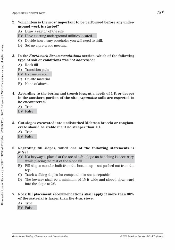
Geotechnical Testing, Observation, and Documentation © 2008 American Society of civil Engineers
Appendix b: Answer keys 187
2. Which item is the most important to be performed before any under-ground work is started?A) Draw a sketch of the site.b)* have existing underground utilities located.c) Decide how many boreholes you will need to drill.D) Set up a pre-grade meeting.
3. In the Earthwork Recommendations section, which of the following type of soil or conditions was not addressed?A) rock fillb) transition padsc)* Expansive soilD) on-site materialE) none of above
4. According to the boring and trench logs, at a depth of 1 ft or deeper in the southern portion of the site, expansive soils are expected to be encountered.A) trueb)* False
5. Cut slopes excavated into undisturbed Mehrten breccia or conglom-erate should be stable if cut no steeper than 1:1.A) trueb)* False
6. Regarding fill slopes, which one of the following statements is false?A)* if a keyway is placed at the toe of a 3:1 slope no benching is necessary
while placing the rest of the slope fill.b) Fill slopes must be built from the bottom up—not pushed out from the
top.c) track walking slopes for compaction is not acceptable.D) the keyway shall be a minimum of 15 ft wide and sloped downward
into the slope at 2%.
7. Rock fill placement recommendations shall apply if more than 30% of the material is larger than the 4-in. sieve.A) trueb)* False
Dow
nloa
ded
from
asc
elib
rary
.org
by
SOU
TH
ER
N C
AL
IFO
RN
IA U
NIV
ER
SIT
Y o
n 08
/27/
13. C
opyr
ight
ASC
E. F
or p
erso
nal u
se o
nly;
all
righ
ts r
eser
ved.
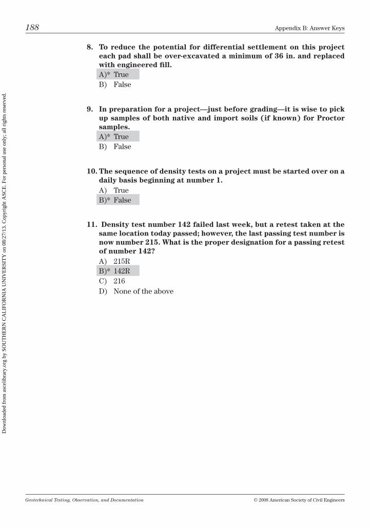
Geotechnical Testing, Observation, and Documentation © 2008 American Society of civil Engineers
188 Appendix b: Answer keys
8. To reduce the potential for differential settlement on this project each pad shall be over-excavated a minimum of 36 in. and replaced with engineered fill.A)* trueb) False
9. In preparation for a project—just before grading—it is wise to pick up samples of both native and import soils (if known) for Proctor samples.A)* trueb) False
10. The sequence of density tests on a project must be started over on a daily basis beginning at number 1.A) trueb)* False
11. Density test number 142 failed last week, but a retest taken at the same location today passed; however, the last passing test number is now number 215. What is the proper designation for a passing retest of number 142?A) 215rb)* 142rc) 216D) none of the above
Dow
nloa
ded
from
asc
elib
rary
.org
by
SOU
TH
ER
N C
AL
IFO
RN
IA U
NIV
ER
SIT
Y o
n 08
/27/
13. C
opyr
ight
ASC
E. F
or p
erso
nal u
se o
nly;
all
righ
ts r
eser
ved.
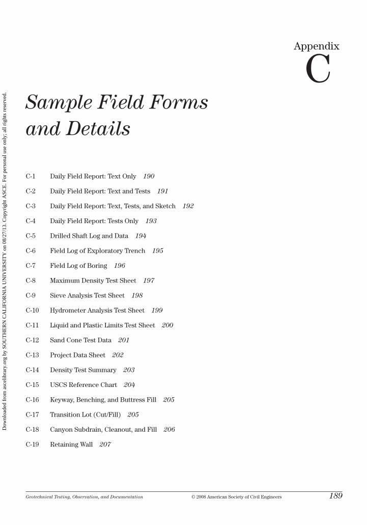
Geotechnical Testing, Observation, and Documentation © 2008 American Society of civil Engineers 189
Appendix
cSample Field Forms and Details
c-1 Daily Field report: text only 190
c-2 Daily Field report: text and tests 191
c-3 Daily Field report: text, tests, and Sketch 192
c-4 Daily Field report: tests only 193
c-5 Drilled Shaft log and Data 194
c-6 Field log of Exploratory trench 195
c-7 Field log of boring 196
c-8 maximum Density test Sheet 197
c-9 Sieve Analysis test Sheet 198
c-10 hydrometer Analysis test Sheet 199
c-11 liquid and Plastic limits test Sheet 200
c-12 Sand cone test Data 201
c-13 Project Data Sheet 202
c-14 Density test Summary 203
c-15 uScS reference chart 204
c-16 keyway, benching, and buttress Fill 205
c-17 transition lot (cut/Fill) 205
c-18 canyon Subdrain, cleanout, and Fill 206
c-19 retaining Wall 207
Dow
nloa
ded
from
asc
elib
rary
.org
by
SOU
TH
ER
N C
AL
IFO
RN
IA U
NIV
ER
SIT
Y o
n 08
/27/
13. C
opyr
ight
ASC
E. F
or p
erso
nal u
se o
nly;
all
righ
ts r
eser
ved.
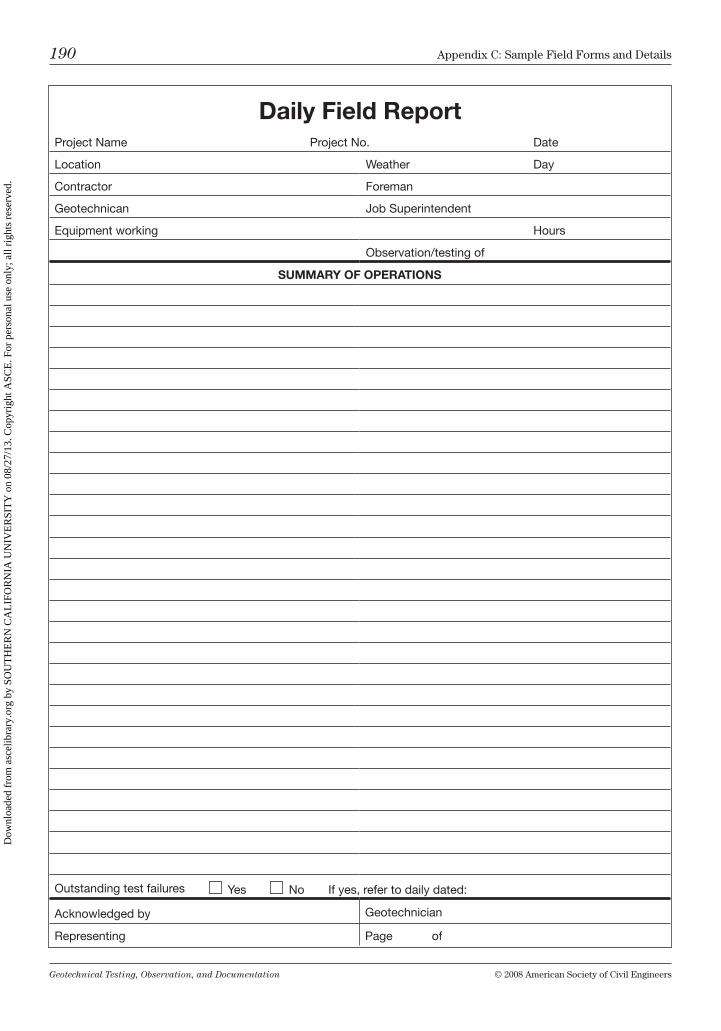
Geotechnical Testing, Observation, and Documentation © 2008 American Society of civil Engineers
190 Appendix c: Sample Field Forms and Details
Daily Field ReportProject Name Project No. Date
Location Weather Day
Contractor Foreman
Geotechnican Job Superintendent
Equipment working Hours
Observation/testing of
SUMMARY OF OPERATIONS
Outstanding test failures Yes No If yes, refer to daily dated:
Acknowledged by Geotechnician
Representing Page of
Dow
nloa
ded
from
asc
elib
rary
.org
by
SOU
TH
ER
N C
AL
IFO
RN
IA U
NIV
ER
SIT
Y o
n 08
/27/
13. C
opyr
ight
ASC
E. F
or p
erso
nal u
se o
nly;
all
righ
ts r
eser
ved.
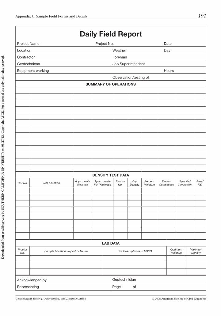
Geotechnical Testing, Observation, and Documentation © 2008 American Society of civil Engineers
Appendix c: Sample Field Forms and Details 191
Daily Field ReportProject Name Project No. Date
Location Weather Day
Contractor Foreman
Geotechnican Job Superintendent
Equipment working Hours
Observation/testing of
SUMMARY OF OPERATIONS
DENSITY TEST DATA
Test No. Test LocationApproximate
ElevationApproximate Fill Thickness
Proctor No.
Dry Density
Percent Moisture
Percent Compaction
Specified Compaction
Pass/Fail
LAB DATA
Proctor No. Sample Location: Import or Native Soil Description and USCS Optimum
MoistureMaximum Density
Acknowledged by Geotechnician
Representing Page of
Dow
nloa
ded
from
asc
elib
rary
.org
by
SOU
TH
ER
N C
AL
IFO
RN
IA U
NIV
ER
SIT
Y o
n 08
/27/
13. C
opyr
ight
ASC
E. F
or p
erso
nal u
se o
nly;
all
righ
ts r
eser
ved.
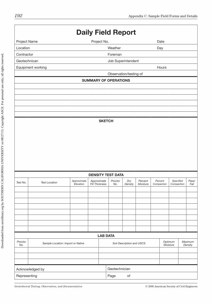
Geotechnical Testing, Observation, and Documentation © 2008 American Society of civil Engineers
192 Appendix c: Sample Field Forms and Details
Daily Field ReportProject Name Project No. Date
Location Weather Day
Contractor Foreman
Geotechnican Job Superintendent
Equipment working Hours
Observation/testing of
SUMMARY OF OPERATIONS
SKETCH
DENSITY TEST DATA
Test No. Test LocationApproximate
ElevationApproximate Fill Thickness
Proctor No.
Dry Density
Percent Moisture
Percent Compaction
Specified Compaction
Pass/Fail
LAB DATA
Proctor No. Sample Location: Import or Native Soil Description and USCS Optimum
MoistureMaximum Density
Acknowledged by Geotechnician
Representing Page of
Dow
nloa
ded
from
asc
elib
rary
.org
by
SOU
TH
ER
N C
AL
IFO
RN
IA U
NIV
ER
SIT
Y o
n 08
/27/
13. C
opyr
ight
ASC
E. F
or p
erso
nal u
se o
nly;
all
righ
ts r
eser
ved.
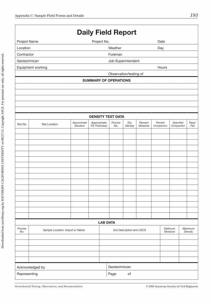
Geotechnical Testing, Observation, and Documentation © 2008 American Society of civil Engineers
Appendix c: Sample Field Forms and Details 193
Daily Field ReportProject Name Project No. Date
Location Weather Day
Contractor Foreman
Geotechnican Job Superintendent
Equipment working Hours
Observation/testing of
SUMMARY OF OPERATIONS
DENSITY TEST DATA
Test No. Test LocationApproximate
ElevationApproximate Fill Thickness
Proctor No.
Dry Density
Percent Moisture
Percent Compaction
Specified Compaction
Pass/Fail
LAB DATA
Proctor No. Sample Location: Import or Native Soil Description and USCS Optimum
MoistureMaximum Density
Acknowledged by Geotechnician
Representing Page of
Dow
nloa
ded
from
asc
elib
rary
.org
by
SOU
TH
ER
N C
AL
IFO
RN
IA U
NIV
ER
SIT
Y o
n 08
/27/
13. C
opyr
ight
ASC
E. F
or p
erso
nal u
se o
nly;
all
righ
ts r
eser
ved.
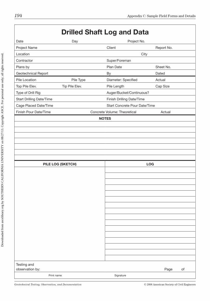
Geotechnical Testing, Observation, and Documentation © 2008 American Society of civil Engineers
194 Appendix c: Sample Field Forms and Details
Drilled Shaft Log and DataDate Day Project No.
Project Name Client Report No.
Location City
Contractor Super/Foreman
Plans by Plan Date Sheet No.
Geotechnical Report By Dated
Pile Location Pile Type Diameter: Specified Actual
Top Pile Elev. Tip Pile Elev. Pile Length Cap Size
Type of Drill Rig Auger/Bucket/Continuous?
Start Drilling Date/Time Finish Drilling Date/Time
Cage Placed Date/Time Start Concrete Pour Date/Time
Finish Pour Date/Time Concrete Volume: Theoretical Actual
NOTES
PILE LOG (SKETCH) LOG
Testing and observation by: Page of
Print name Signature
Dow
nloa
ded
from
asc
elib
rary
.org
by
SOU
TH
ER
N C
AL
IFO
RN
IA U
NIV
ER
SIT
Y o
n 08
/27/
13. C
opyr
ight
ASC
E. F
or p
erso
nal u
se o
nly;
all
righ
ts r
eser
ved.
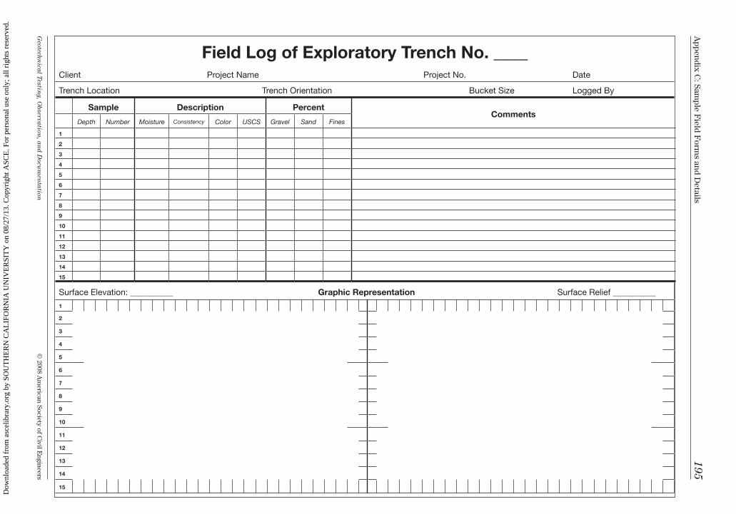
Geotechn
ical Testing, O
bservation, an
d Docu
men
tation
© 2008 A
merican Society of c
ivil Engineers
Appendix c
: Sample F
ield Form
s and Details
195Field Log of Exploratory Trench No. ____
Client Project Name Project No. Date
Trench Location Trench Orientation Bucket Size Logged By
Sample Description PercentComments
Depth Number Moisture Consistency Color USCS Gravel Sand Fines
1
2
3
4
5
6
7
8
9
10
11
12
13
14
15
Surface Elevation: __________ Graphic Representation Surface Relief __________
1
2
3
4
5
6
7
8
9
10
11
12
13
14
15
Dow
nloa
ded
from
asc
elib
rary
.org
by
SOU
TH
ER
N C
AL
IFO
RN
IA U
NIV
ER
SIT
Y o
n 08
/27/
13. C
opyr
ight
ASC
E. F
or p
erso
nal u
se o
nly;
all
righ
ts r
eser
ved.
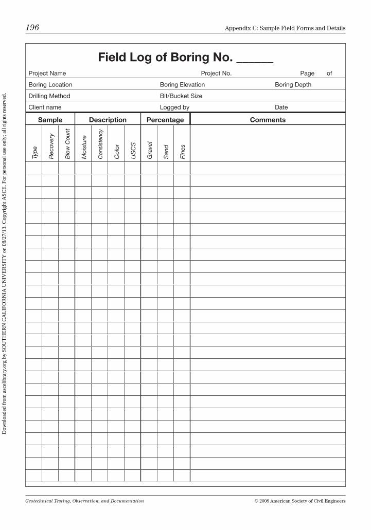
Geotechnical Testing, Observation, and Documentation © 2008 American Society of civil Engineers
196 Appendix c: Sample Field Forms and Details
Field Log of Boring No. ______Project Name Project No. Page of
Boring Location Boring Elevation Boring Depth
Drilling Method Bit/Bucket Size
Client name Logged by Date
Sample Description Percentage Comments
Typ
e
Rec
over
y
Blo
w C
ount
Moi
stur
e
Con
sist
ency
Col
or
US
CS
Gra
vel
San
d
Fine
s
Dow
nloa
ded
from
asc
elib
rary
.org
by
SOU
TH
ER
N C
AL
IFO
RN
IA U
NIV
ER
SIT
Y o
n 08
/27/
13. C
opyr
ight
ASC
E. F
or p
erso
nal u
se o
nly;
all
righ
ts r
eser
ved.
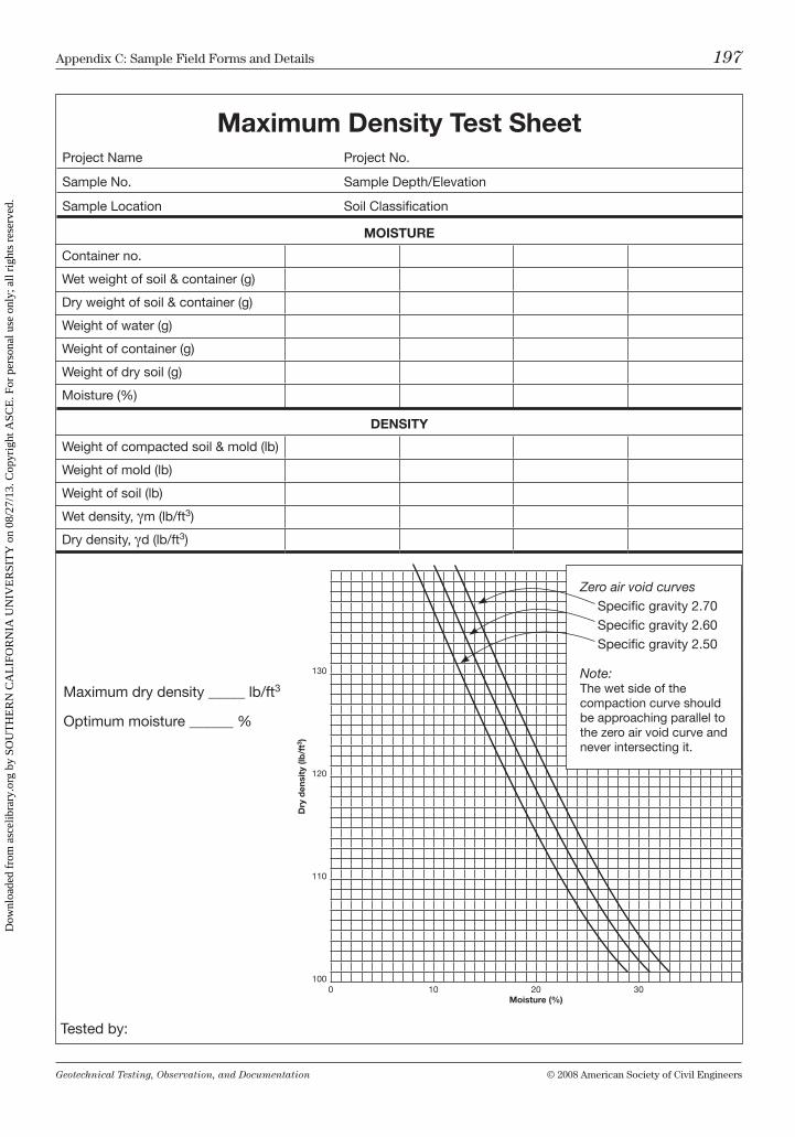
Geotechnical Testing, Observation, and Documentation © 2008 American Society of civil Engineers
Appendix c: Sample Field Forms and Details 197
Maximum Density Test SheetProject Name Project No.
Sample No. Sample Depth/Elevation
Sample Location Soil Classification
MOISTURE
Container no.
Wet weight of soil & container (g)
Dry weight of soil & container (g)
Weight of water (g)
Weight of container (g)
Weight of dry soil (g)
Moisture (%)
DENSITY
Weight of compacted soil & mold (lb)
Weight of mold (lb)
Weight of soil (lb)
Wet density, gm (lb/ft3)
Dry density, gd (lb/ft3)
Dry
den
sity
(lb
/ft3 )
130
120
110
100 0 10 20 30 Moisture (%)
Tested by:
Maximum dry density _____ lb/ft3
Optimum moisture ______ %
Zero air void curvesSpecific gravity 2.70Specific gravity 2.60Specific gravity 2.50
Note:The wet side of the compaction curve should be approaching parallel to the zero air void curve and never intersecting it.
Dow
nloa
ded
from
asc
elib
rary
.org
by
SOU
TH
ER
N C
AL
IFO
RN
IA U
NIV
ER
SIT
Y o
n 08
/27/
13. C
opyr
ight
ASC
E. F
or p
erso
nal u
se o
nly;
all
righ
ts r
eser
ved.
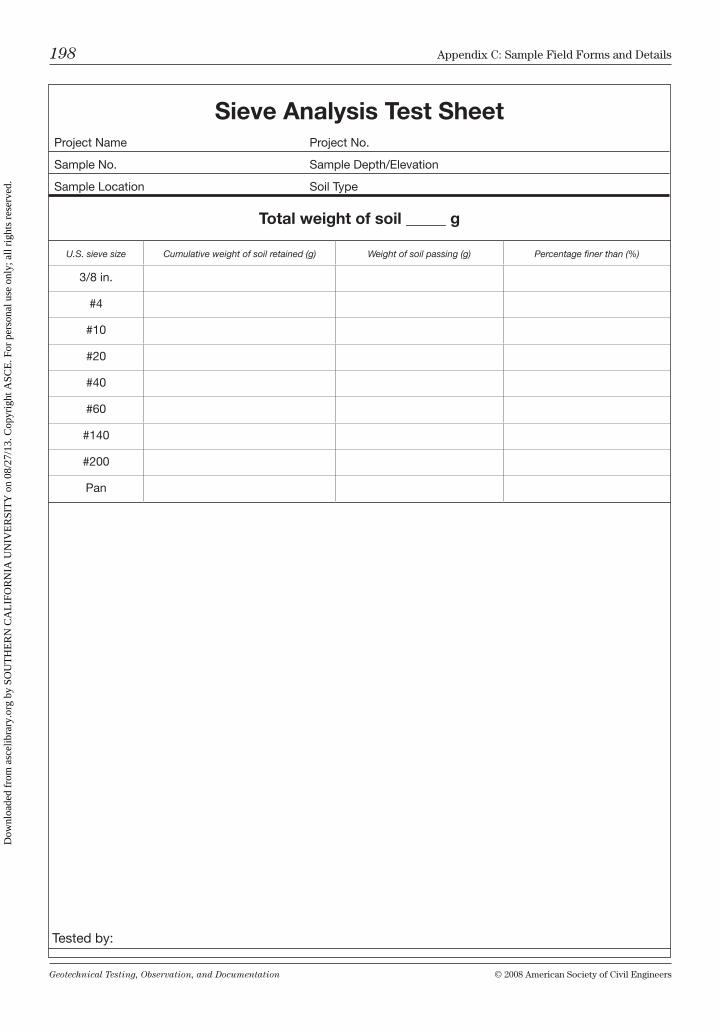
Geotechnical Testing, Observation, and Documentation © 2008 American Society of civil Engineers
198 Appendix c: Sample Field Forms and Details
Sieve Analysis Test SheetProject Name Project No.
Sample No. Sample Depth/Elevation
Sample Location Soil Type
Total weight of soil _____ g
U.S. sieve size Cumulative weight of soil retained (g) Weight of soil passing (g) Percentage finer than (%)
3/8 in.
#4
#10
#20
#40
#60
#140
#200
Pan
Tested by:
Dow
nloa
ded
from
asc
elib
rary
.org
by
SOU
TH
ER
N C
AL
IFO
RN
IA U
NIV
ER
SIT
Y o
n 08
/27/
13. C
opyr
ight
ASC
E. F
or p
erso
nal u
se o
nly;
all
righ
ts r
eser
ved.
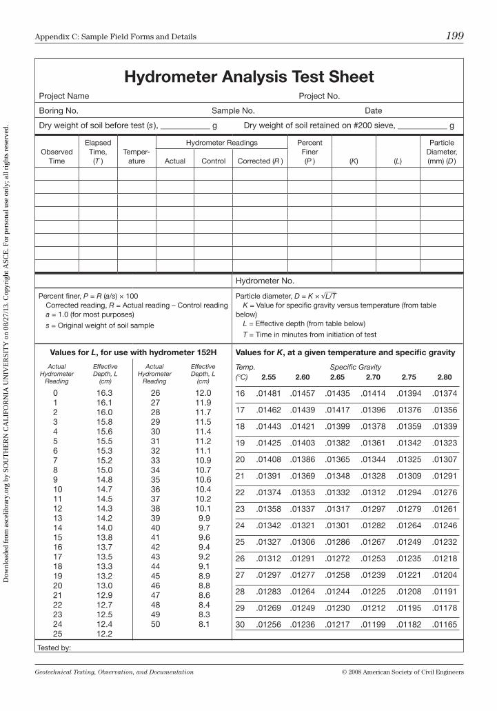
Geotechnical Testing, Observation, and Documentation © 2008 American Society of civil Engineers
Appendix c: Sample Field Forms and Details 199
Hydrometer Analysis Test Sheet Project Name Project No.
Boring No. Sample No. Date
Dry weight of soil before test (s ), ____________ g Dry weight of soil retained on #200 sieve, ____________ g
Observed Time
Elapsed Time,
(T )Temper-
ature
Hydrometer Readings Percent Finer (P ) (K) (L)
Particle Diameter, (mm) (D )Actual Control Corrected (R )
Hydrometer No.
Percent finer, P = R (a/s) × 100 Corrected reading, R = Actual reading – Control reading a = 1.0 (for most purposes)
s = Original weight of soil sample
Particle diameter, D = K × √L/T K = Value for specific gravity versus temperature (from table below) L = Effective depth (from table below)
T = Time in minutes from initiation of test
Values for L, for use with hydrometer 152H Values for K, at a given temperature and specific gravity
Actual Effective Hydrometer Depth, L Reading (cm)
0 16.31 16.12 16.03 15.84 15.65 15.56 15.37 15.28 15.09 14.810 14.711 14.512 14.313 14.214 14.015 13.816 13.717 13.518 13.319 13.220 13.021 12.922 12.723 12.524 12.425 12.2
Actual Effective Hydrometer Depth, L Reading (cm)
26 12.027 11.928 11.729 11.530 11.431 11.232 11.133 10.934 10.735 10.636 10.437 10.238 10.139 9.940 9.741 9.642 9.443 9.244 9.145 8.946 8.847 8.648 8.449 8.350 8.1
Temp. Specific Gravity(°C) 2.55 2.60 2.65 2.70 2.75 2.80
16 .01481 .01457 .01435 .01414 .01394 .01374
17 .01462 .01439 .01417 .01396 .01376 .01356
18 .01443 .01421 .01399 .01378 .01359 .01339
19 .01425 .01403 .01382 .01361 .01342 .01323
20 .01408 .01386 .01365 .01344 .01325 .01307
21 .01391 .01369 .01348 .01328 .01309 .01291
22 .01374 .01353 .01332 .01312 .01294 .01276
23 .01358 .01337 .01317 .01297 .01279 .01261
24 .01342 .01321 .01301 .01282 .01264 .01246
25 .01327 .01306 .01286 .01267 .01249 .01232
26 .01312 .01291 .01272 .01253 .01235 .01218
27 .01297 .01277 .01258 .01239 .01221 .01204
28 .01283 .01264 .01244 .01225 .01208 .01191
29 .01269 .01249 .01230 .01212 .01195 .01178
30 .01256 .01236 .01217 .01199 .01182 .01165
Tested by:
Dow
nloa
ded
from
asc
elib
rary
.org
by
SOU
TH
ER
N C
AL
IFO
RN
IA U
NIV
ER
SIT
Y o
n 08
/27/
13. C
opyr
ight
ASC
E. F
or p
erso
nal u
se o
nly;
all
righ
ts r
eser
ved.
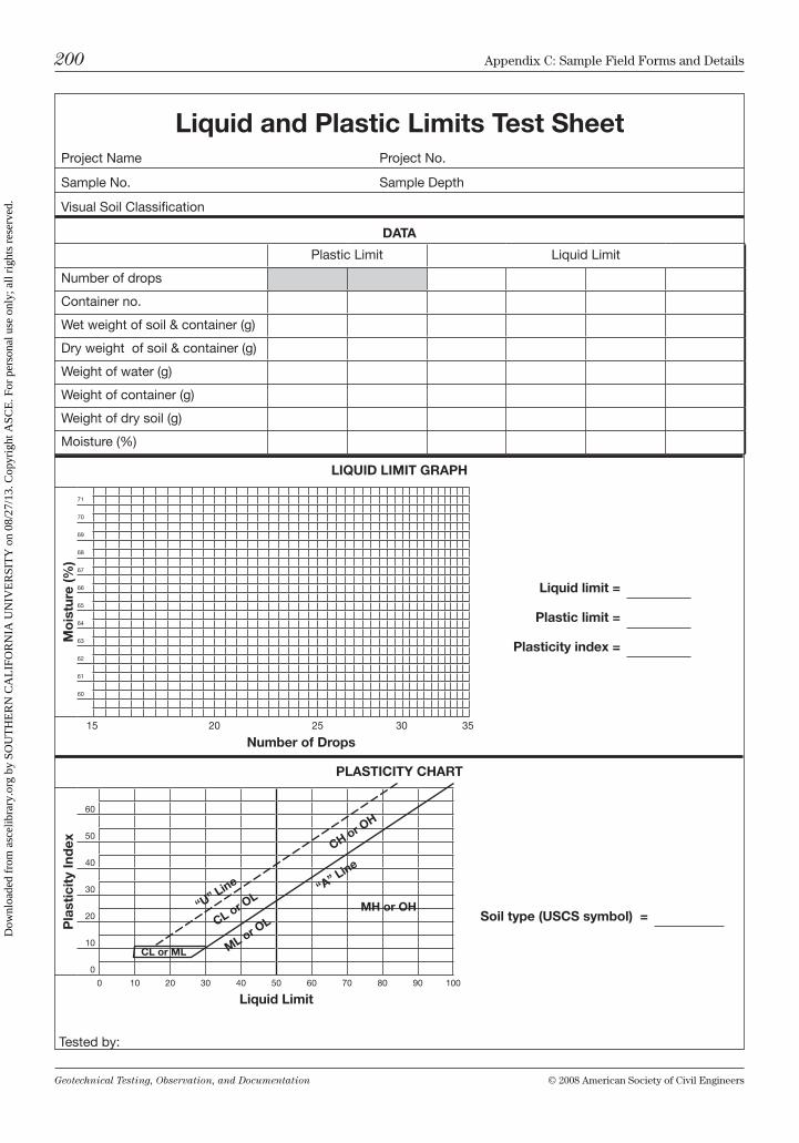
Geotechnical Testing, Observation, and Documentation © 2008 American Society of civil Engineers
200 Appendix c: Sample Field Forms and Details
Liquid and Plastic Limits Test SheetProject Name Project No.
Sample No. Sample Depth
Visual Soil Classification
DATA
Plastic Limit Liquid Limit
Number of drops
Container no.
Wet weight of soil & container (g)
Dry weight of soil & container (g)
Weight of water (g)
Weight of container (g)
Weight of dry soil (g)
Moisture (%)
LIQUID LIMIT GRAPH
Mo
istu
re (%
)
71
70
69
68
67
66
65
64
63
62
61
60
15 20 25 30 35
Number of Drops
PLASTICITY CHART
Pla
stic
ity
Ind
ex
60
50
40
30
20
10
0
0 10 20 30 40 50 60 70 80 90 100
Liquid Limit
Tested by:
Liquid limit =
Plastic limit =
Plasticity index =
Soil type (USCS symbol) =MH or OH
CH or OH
CL or OL
ML or OL
“U” L
ine “A” L
ine
CL or ML
Dow
nloa
ded
from
asc
elib
rary
.org
by
SOU
TH
ER
N C
AL
IFO
RN
IA U
NIV
ER
SIT
Y o
n 08
/27/
13. C
opyr
ight
ASC
E. F
or p
erso
nal u
se o
nly;
all
righ
ts r
eser
ved.
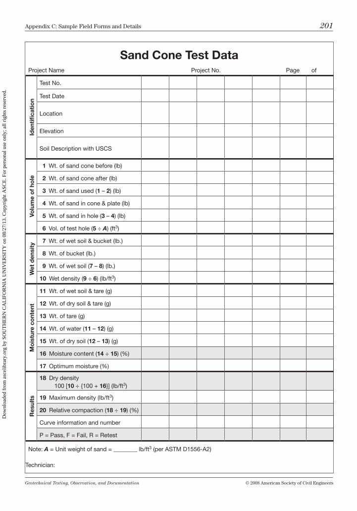
Geotechnical Testing, Observation, and Documentation © 2008 American Society of civil Engineers
Appendix c: Sample Field Forms and Details 201
Sand Cone Test Data Project Name Project No. Page of
Iden
tifi
cati
on
Test No.
Test Date
Location
Elevation
Soil Description with USCS
Volu
me
of
hole
1 Wt. of sand cone before (lb)
2 Wt. of sand cone after (lb)
3 Wt. of sand used (1 – 2) (lb)
4 Wt. of sand in cone & plate (lb)
5 Wt. of sand in hole (3 – 4) (lb)
6 Vol. of test hole (5 ÷ A) (ft3)
Wet
den
sity
7 Wt. of wet soil & bucket (lb.)
8 Wt. of bucket (lb.)
9 Wt. of wet soil (7 – 8) (lb.)
10 Wet density (9 ÷ 6) (lb/ft3)
Mo
istu
re c
ont
ent
11 Wt. of wet soil & tare (g)
12 Wt. of dry soil & tare (g)
13 Wt. of tare (g)
14 Wt. of water (11 – 12) (g)
15 Wt. of dry soil (12 – 13) (g)
16 Moisture content (14 ÷ 15) (%)
17 Optimum moisture (%)
Res
ults
18 Dry density 100 [10 ÷ {100 + 16}] (lb/ft3)
19 Maximum density (lb/ft3)
20 Relative compaction (18 ÷ 19) (%)
Curve information and number
P = Pass, F = Fail, R = Retest
Note: A = Unit weight of sand = ________ lb/ft3 (per ASTM D1556-A2)
Technician:
Dow
nloa
ded
from
asc
elib
rary
.org
by
SOU
TH
ER
N C
AL
IFO
RN
IA U
NIV
ER
SIT
Y o
n 08
/27/
13. C
opyr
ight
ASC
E. F
or p
erso
nal u
se o
nly;
all
righ
ts r
eser
ved.
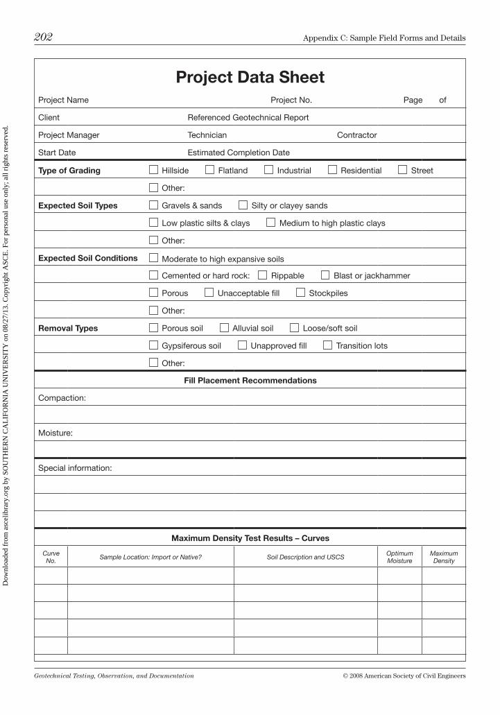
Geotechnical Testing, Observation, and Documentation © 2008 American Society of civil Engineers
202 Appendix c: Sample Field Forms and Details
Project Data SheetProject Name Project No. Page of
Client Referenced Geotechnical Report
Project Manager Technician Contractor
Start Date Estimated Completion Date
Type of Grading Hillside Flatland Industrial Residential Street
Other:
Expected Soil Types Gravels & sands Silty or clayey sands
Low plastic silts & clays Medium to high plastic clays
Other:
Expected Soil Conditions Moderate to high expansive soils
Cemented or hard rock: Rippable Blast or jackhammer
Porous Unacceptable fill Stockpiles
Other:
Removal Types Porous soil Alluvial soil Loose/soft soil
Gypsiferous soil Unapproved fill Transition lots
Other:
Fill Placement Recommendations
Compaction:
Moisture:
Special information:
Maximum Density Test Results – Curves
Curve No. Sample Location: Import or Native? Soil Description and USCS Optimum
MoistureMaximum Density
Dow
nloa
ded
from
asc
elib
rary
.org
by
SOU
TH
ER
N C
AL
IFO
RN
IA U
NIV
ER
SIT
Y o
n 08
/27/
13. C
opyr
ight
ASC
E. F
or p
erso
nal u
se o
nly;
all
righ
ts r
eser
ved.
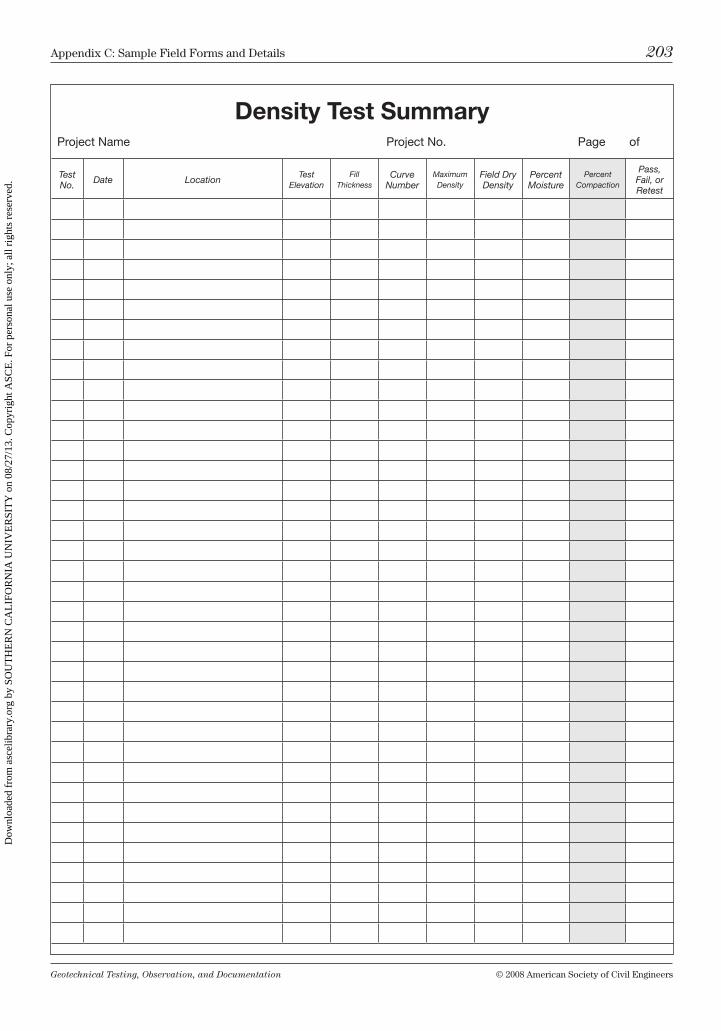
Geotechnical Testing, Observation, and Documentation © 2008 American Society of civil Engineers
Appendix c: Sample Field Forms and Details 203
Density Test Summary Project Name Project No. Page of
Test No. Date Location
Test Elevation
Fill Thickness
Curve Number
Maximum Density
Field Dry Density
Percent Moisture
Percent Compaction
Pass, Fail, or Retest
Dow
nloa
ded
from
asc
elib
rary
.org
by
SOU
TH
ER
N C
AL
IFO
RN
IA U
NIV
ER
SIT
Y o
n 08
/27/
13. C
opyr
ight
ASC
E. F
or p
erso
nal u
se o
nly;
all
righ
ts r
eser
ved.
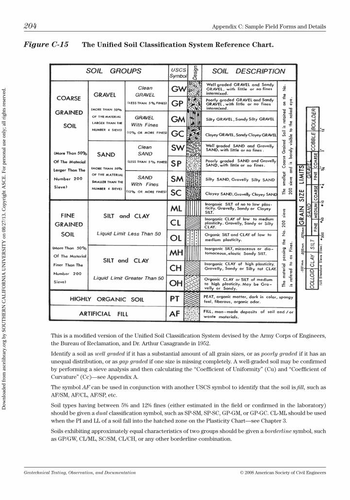
Geotechnical Testing, Observation, and Documentation © 2008 American Society of civil Engineers
204 Appendix c: Sample Field Forms and Details
Figure C-15 The Unified Soil Classification System Reference Chart.
this is a modified version of the unified Soil classification System devised by the Army corps of Engineers, the bureau of reclamation, and Dr. Arthur casagrande in 1952.
identify a soil as well graded if it has a substantial amount of all grain sizes, or as poorly graded if it has an unequal distribution, or as gap graded if one size is missing completely. A well-graded soil may be confirmed by performing a sieve analysis and then calculating the “coefficient of uniformity” (cu) and “coefficient of curvature” (cc)—see Appendix A.
the symbol AF can be used in conjunction with another uScS symbol to identify that the soil is fill, such as AF/Sm, AF/cl, AF/SP, etc.
Soil types having between 5% and 12% fines (either estimated in the field or confirmed in the laboratory) should be given a dual classification symbol, such as SP-Sm, SP-Sc, GP-Gm, or GP-Gc. cl-ml should be used when the Pi and ll of a soil fall into the hatched zone on the Plasticity chart—see chapter 3.
Soils exhibiting approximately equal characteristics of two groups should be given a borderline symbol, such as GP/GW, cl/ml, Sc/Sm, cl/ch, or any other borderline combination.
Dow
nloa
ded
from
asc
elib
rary
.org
by
SOU
TH
ER
N C
AL
IFO
RN
IA U
NIV
ER
SIT
Y o
n 08
/27/
13. C
opyr
ight
ASC
E. F
or p
erso
nal u
se o
nly;
all
righ
ts r
eser
ved.
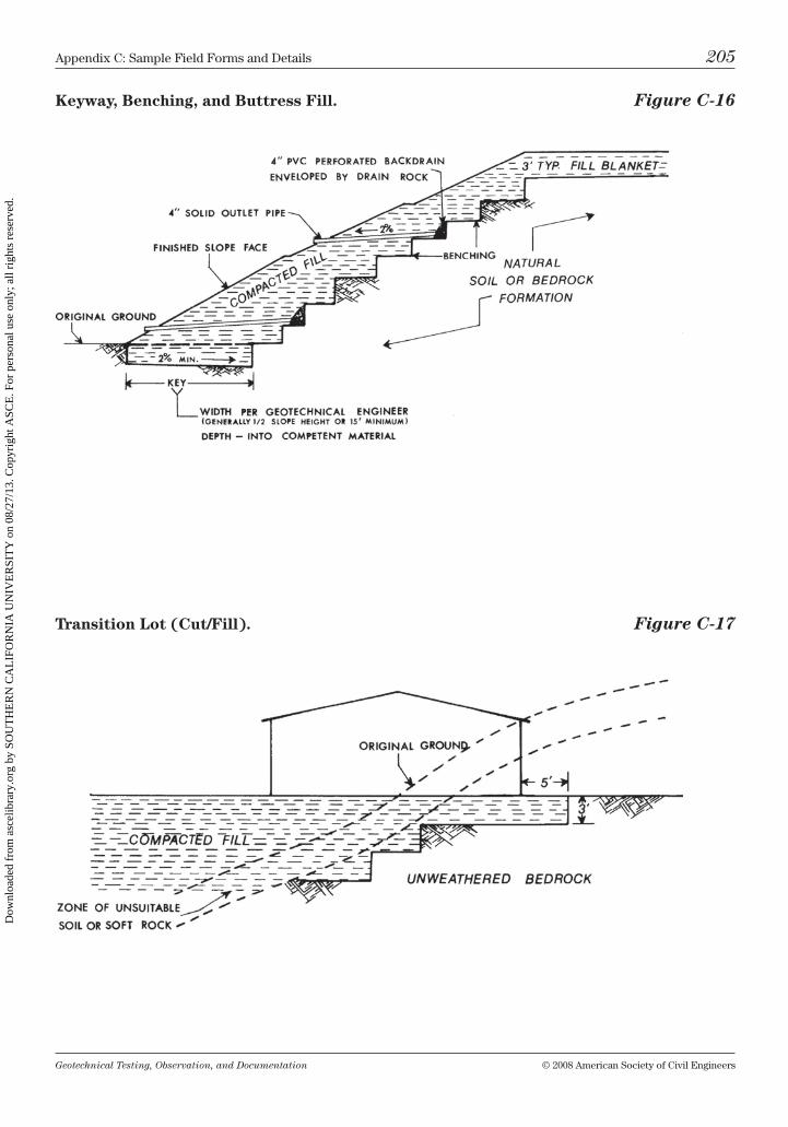
Geotechnical Testing, Observation, and Documentation © 2008 American Society of civil Engineers
Appendix c: Sample Field Forms and Details 205
Keyway, Benching, and Buttress Fill. Figure C-16
Transition Lot (Cut/Fill). Figure C-17
Dow
nloa
ded
from
asc
elib
rary
.org
by
SOU
TH
ER
N C
AL
IFO
RN
IA U
NIV
ER
SIT
Y o
n 08
/27/
13. C
opyr
ight
ASC
E. F
or p
erso
nal u
se o
nly;
all
righ
ts r
eser
ved.
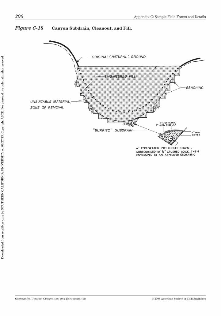
Geotechnical Testing, Observation, and Documentation © 2008 American Society of civil Engineers
206 Appendix c: Sample Field Forms and Details
Figure C-18 Canyon Subdrain, Cleanout, and Fill.
Dow
nloa
ded
from
asc
elib
rary
.org
by
SOU
TH
ER
N C
AL
IFO
RN
IA U
NIV
ER
SIT
Y o
n 08
/27/
13. C
opyr
ight
ASC
E. F
or p
erso
nal u
se o
nly;
all
righ
ts r
eser
ved.
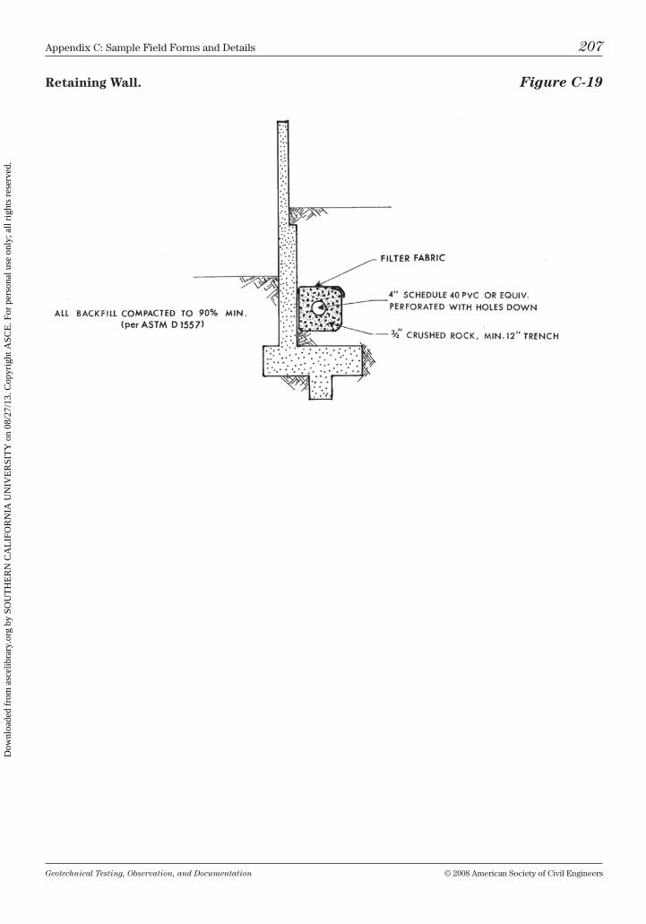
Geotechnical Testing, Observation, and Documentation © 2008 American Society of civil Engineers
Appendix c: Sample Field Forms and Details 207
Retaining Wall. Figure C-19
Dow
nloa
ded
from
asc
elib
rary
.org
by
SOU
TH
ER
N C
AL
IFO
RN
IA U
NIV
ER
SIT
Y o
n 08
/27/
13. C
opyr
ight
ASC
E. F
or p
erso
nal u
se o
nly;
all
righ
ts r
eser
ved.

This page intentionally left blank
Dow
nloa
ded
from
asc
elib
rary
.org
by
SOU
TH
ER
N C
AL
IFO
RN
IA U
NIV
ER
SIT
Y o
n 08
/27/
13. C
opyr
ight
ASC
E. F
or p
erso
nal u
se o
nly;
all
righ
ts r
eser
ved.
Geotechnical Testing, Observation, and Documentation © 2008 American Society of civil Engineers 209
Afterword
my involvement with geotechnical testing and observation has spanned five decades, from the 1960s through the millennium. in that time, my position has varied from junior technician to company owner. these positions have given me a very good overall perspective of the geotechnical business. Without a doubt, the biggest problem the industry faces is the lack of a good training/reference manual. but who should write it? Well, first, it should be a technician. Second, it should be one who knows every aspect of this diverse profession. And third, it should be someone who has the skill, the patience, and the resolve to compile all this information in a format that can be understood and appreciated by new hires and veteran soil techs alike. of all the technicians that i have met, tim Davis most accurately fits this bill.
tim Davis is one of those rare individuals who has the ability to take a complex idea and break it down into easy-to-follow steps. consequently, his book is very user friendly.
the first time i had the pleasure of working with tim was in the early 1970s. We were on the quality control staff at a nuclear power plant. We also did geo-technical drilling exploration on the mX missile siting project. our paths have crossed many times since, and each time tim has been in a well-respected posi-tion. Whether he was training, supervising, or trouble-shooting, he was always the technician who was entrusted with the most difficult projects.
Even today, as construction Supervisor for the second largest county in the united States, tim is always ready to learn and take on new challenges. it is a daunting task that he has undertaken in northern Arizona. but he is turning the situation around and getting contractors and quality control companies alike to adhere to the ibc standards.
i cannot think of anyone who is more qualified to write this book. i give it my whole-hearted endorsement.
Robert D. KingSenior Supervisory Technician
Dow
nloa
ded
from
asc
elib
rary
.org
by
SOU
TH
ER
N C
AL
IFO
RN
IA U
NIV
ER
SIT
Y o
n 08
/27/
13. C
opyr
ight
ASC
E. F
or p
erso
nal u
se o
nly;
all
righ
ts r
eser
ved.

This page intentionally left blank
Dow
nloa
ded
from
asc
elib
rary
.org
by
SOU
TH
ER
N C
AL
IFO
RN
IA U
NIV
ER
SIT
Y o
n 08
/27/
13. C
opyr
ight
ASC
E. F
or p
erso
nal u
se o
nly;
all
righ
ts r
eser
ved.
Geotechnical Testing, Observation, and Documentation © 2008 American Society of civil Engineers 211
Index
aggregate base 62–63, 125AStm D1556: see test, sand coneAStm D1557: see test, ProctorAStm D422: see tests; hydrometer analysis, sieve analysisAStm D4318: see test, plastic and liquid limitsAStm D6938: see test, nuclear gaugeAtterberg limits see test, plastic and liquid limits
backfill trench 47, 51, 57, 92–94, 108–109, 118–119, 120; wall 71, 144tbackscatter method 55, 57, 63baskets, gabion 70, 71fbenching 65, 82, 85, 100, 121blow count 7t, 15, 17f, 19boring log 15, 17f, 19, 104–105, 133–137, 196buttress 65, 82, 205
casagrande, Arthur 1cementation 8t; cemented 11–12, 19, 21, 61, 82; excavatability 14tchapter questions 9–10, 23, 45–46, 59–60, 75–76, 80, 90, 97, 139–140communication 74, 79,84, 85, 94–95, 96, 103, 109compaction 61, 63, 82; of aggregate base 120; equipment 25, 63, 68, 118, 141–144; on
flatland projects 62; laboratory 25–31; percent (degree) 26, 47, 81; process 68; recommendation (specification) 107, 117–118; during road construction 62–63; of rock fill 119; of slopes 64, 85, 121; of trench backfill 120, 144; of wall fill 144
construction 107–109; road 62–64conversions 145–146curing 29, 43cut slope 65, 68, 85, 102, 121
daily field report: see report, daily fieldDFr: see report, daily fielddifferential settlement 47, 68–69, 73, 119, 123dilatancy: see test, shakingdirect transmission method 55, 57, 63documentation 84; field reports 74, 87–89, 93–96, 108; final report 81; paper trail
109–110; of the site investigation 103; of testing 87drill: rod 14–15, 20; for nuclear gauge 63; rig 14, 16f, 20, 104
Dow
nloa
ded
from
asc
elib
rary
.org
by
SOU
TH
ER
N C
AL
IFO
RN
IA U
NIV
ER
SIT
Y o
n 08
/27/
13. C
opyr
ight
ASC
E. F
or p
erso
nal u
se o
nly;
all
righ
ts r
eser
ved.
Geotechnical Testing, Observation, and Documentation © 2008 American Society of civil Engineers
212 index
drilling 15, 22; crew experienced in 21, 103; of deep foundations 69; prior to 11; for blasting 67f
dry strength 3, 8t
expansive soil 39, 47, 62, 73exploration techniques: see sampling methods
field file 106field report: see report, daily fieldfill: canyon 66f; cut and 68–69; diagrams 204–206; distinguishing from natural
soil 4–5; exploration and 11; hillside grading and 64–65; observation of 84–85; preparation prior to 62; project issues and 84; recommendations for placement of 117–119; rock 65–68; testing of 86–87; testing frequency 118; top 10 reasons why 84; undocumented 61
fill slope 64, 85, 121fines: discerning 3, 7t, 204; segregation and 63; sieve analysis and 32flatland projects 62foundations 69, 70; differential support and 68, 73, 119; recommendations 122–123
geology 77–80; site 114–115geophysical seismic refraction survey: see survey, geophysical seismic refractiongeotechnical report: see report, geotechnicalgrading 61–63, 82; classification during 2, 4; hillside 64–69; pre-grade meeting 82,
107; prior to 11; safety 100, 102; tracking operations 107–109grain size 1, 2, 6t; analysis of 31–38, 204
hydrometer analysis 34–39; apparatus 34–35; calculations 36–38; procedure 35–36
keyway 64, 77, 82, 121, 205
liquid limit 41, 43; moisture content and 6; test 39–44logs: boring log 17f, 82, 133–137, 196; drilled shaft 69, 194; trench log 12, 13f, 82,
104–105, 130–132, 195loss prevention 91–97; case history example 91–94; field report writing 94–98
measures 144–145modified Proctor: see test, Proctormoisture content (percent moisture) 6t; aggregate base and 126; expansive soil and
62; field tests 47–57; laboratory tests 25–31; recommendations 117; rock fill 119; subgrade soil and 63
nuclear gauge: see test, nuclear gaugen value 7t, 15t, 15, 20
observation 84–85; classification and 2–3, communication of 94; deep foundations and 69; field testing and 59; hillside grading and 65; records of 81, 87; rock fill 65, 68
odor 1, 2, 8t
pads: cut/fill/transition 68–69, 119; material for 70, 119
Dow
nloa
ded
from
asc
elib
rary
.org
by
SOU
TH
ER
N C
AL
IFO
RN
IA U
NIV
ER
SIT
Y o
n 08
/27/
13. C
opyr
ight
ASC
E. F
or p
erso
nal u
se o
nly;
all
righ
ts r
eser
ved.
Geotechnical Testing, Observation, and Documentation © 2008 American Society of civil Engineers
index 213
particle size: see grain sizeplastic limit 39, 41plasticity: classification and 1; dry strength and 8t; when moist 9t; graph 44; lab
testing and 116plasticity index: see test, plastic and liquid limitsporosity 4–5pre-job meeting 74, 103, 105–106; pre-con 82, 107, 117probe (hand probe) 70, 73, 86, 142, 143fProctor, r.r. 25project management 81–90; communication 85, 94–95, 109; construction 107–110;
documentation 87–89, 94–95, 96, 109–110; initial site visit 104; pre-grade meeting 82, 107; pre-job meeting 105–106; preparation 81–83; project data sheet 83f; project preparation 106–107; tracking operations 108–109
report, daily field 87–89, 94–98, 106, 108, 109; documentation with 74, 87, 88f, 94, 95f, 96; field file including 106; sample form 190–193
report, geotechnical 81–82; density test and 54; exploration and 11; equipment recommendations 141; example 111–138; review of recommendations 61–62, 64, 68, 70, 73, 81–82, 106–107, 141; soil technician and 61, 141
ring sampling 18f, 19–20rippability: see rock excavation studyroad construction 62–64rock excavation study 12, 13, 14rock fill 65, 68, 100–101, 143t
safety 99–102; factor of 123; grading 82, 100, 102, 107; nuclear gauge 55, 57; technician’s 73; testing and 86; trench 12, 99–100
sampling methods 11–23; backhoe trenches 11–12; ring 19–20; rock excavation study 12, 13; split barrel 14–19; tube 20–22
sand cone test: see test, sand conesand equivalency (AStm D2914) 65sieve analysis 31–34, 198, 204; apparatus 32; calculations 32; procedure 32; sieves
33fsite investigation 103–105site plan 11, 105, 128fsoaking 32soil, natural 4–5soil classification 1–10, 7t, 204; descriptive classification terminology 5–9; in the field
2; oShA 100; soil types 2–5; unified Soil classification System 1–2, 204; split barrel sampling and 14, tube sampling and 20
soil technicians: steps to success 73–75; supplies and tools checklist 141split barrel sampling 14, 15, 18–19; boring log 17f; procedure 15, 19stabilization fabric 63, 120study, rock excavation 12, 13, 14survey, geophysical seismic refraction 12, 14
terminology: see soil engineering terminologytest, field density 47–60; failure/retest 87, 108; frequency 118–119; nuclear gauge test
55–59; as related to Proctor 26; safety while taking 102; sand cone test 48–55; test sheets 191–193, 201–203
Dow
nloa
ded
from
asc
elib
rary
.org
by
SOU
TH
ER
N C
AL
IFO
RN
IA U
NIV
ER
SIT
Y o
n 08
/27/
13. C
opyr
ight
ASC
E. F
or p
erso
nal u
se o
nly;
all
righ
ts r
eser
ved.
Geotechnical Testing, Observation, and Documentation © 2008 American Society of civil Engineers
214 index
test, liquid limits: see test, plastic and liquid limitstest, moisture/density: see test, field densitytest, nuclear gauge 55–59; backscatter method 55, 57, 63; direct transmission method
55, 57, 63; performing a test 55–57; safety 57–58; test biases 58–59test, plastic and liquid limits 39–44; apparatus 39, 40f; calculations 43–44; liquid limit
41, 42f, 43; plastic limit 41; preparation 40; procedure 40–41test, Proctor 25–31, 47–48; apparatus 26, 28; calculations 31; check point equipment
142; procedure 28–31; project preparation 107, 108; recommendations 118; rock fill and 65; synopsis 26; when choosing 109
test, sand cone 48–55; apparatus 48–50, 49f; overview 48; plate and cone calibration 50–51; preparation 50; procedure 51–54; test biases 54–55
test, shaking (dilatancy) 3test, sieve analysis 31–34testing 86–87testing and observation 107–109tests, laboratory 25–46, 105, 115, 138; hydrometer analysis 34–39; nuclear gauge test
55–59; plastic and liquid limits 39–44; Proctor test 25–31; sieve analysis 31–34; test sheets 197–201
tools, technician 142–143transition lot/pad 68, 82, 83f, 205trench log 12, 13f, 82, 104–105, 130–132, 195trenches: exploration 11–12; safety 99–100; trench log 12, 13f, 82, 104–105, 130–132,
195tube sampling 20–22
unified Soil classification System 1–2; reference chart 204uScS: see unified Soil classification System
walls: block 70–71; reinforced concrete 73; retaining 70–73, 207; rockery 71–73weight conversions 145–146
Dow
nloa
ded
from
asc
elib
rary
.org
by
SOU
TH
ER
N C
AL
IFO
RN
IA U
NIV
ER
SIT
Y o
n 08
/27/
13. C
opyr
ight
ASC
E. F
or p
erso
nal u
se o
nly;
all
righ
ts r
eser
ved.
Geotechnical Testing, Observation, and Documentation © 2008 American Society of civil Engineers
About the Author
tim Davis lives in Flagstaff, Arizona, with his wife teresa, and works in the public works engineering department for coconino county. During tim’s career he has been involved in multiple phases of geotechnical construction, includ-ing investigation, lab and field testing, observation, inspection, report writing, supervision and training. tim enjoys the outdoors and is an avid hiker; he plays ice hockey and disc golf for recreation.
tim currently holds a level iv nicEt certification in geotechnical construction, and has recently passed all of the elements necessary to obtain level iv nicEts in both geotechnical exploration and geotechnical generalist.
Dow
nloa
ded
from
asc
elib
rary
.org
by
SOU
TH
ER
N C
AL
IFO
RN
IA U
NIV
ER
SIT
Y o
n 08
/27/
13. C
opyr
ight
ASC
E. F
or p
erso
nal u
se o
nly;
all
righ
ts r
eser
ved.