Embed Size (px)
Citation preview

Geothermal Energy in the Oil FieldDevelopments and Opportunities
Part of the E-Symposium Series
August 20, 200911 am (Eastern)
Presented by:
Michael Sullivan, M.Sci., Groundwater Services International, LLCDina L. Lopez, Ph.D, Ohio University
ObjectivesTo explain the various geothermal resources available and the
current types of exploitation methods.
To inform the gas and oil community about the potential applications of emerging technologies to exploit geothermal energy taking advantage of the oil and gas developments, such as geothermal exploitation coupled with oil and gas production.
To provide case studies of projects in which geothermal technology is being implemented and future areas where it may also be applicable.

Outline• Geothermal Energy Review: History, Resources, and Current
Production Types
• Enhanced Geothermal Systems (EGS)
• Geothermal Energy from Oil and Gas Wells
• Case Studies: Current Enhanced Geothermal ExploitationCoproduction of Geothermal Energy (California Oilfields) Steamflood Performance, Kern River Field, CA
Geothermal Energy Review

• Earth’s thermal energy converted to electric energy and other direct uses.
• Earth’s heat comes mainly from radioactive decay.
• Average geothermal gradient: 25-30ºC/km
• Higher thermal gradient at tectonic boundaries.
What is Geothermal Energy?
Geothermal Education Office, 2000

Subduction Zones, Rift Basins, Hot Spots.
First exploited systems were:
Hydrothermal Systems are found where shallow heat causes thermal fluid convection. The hot hydrothermal fluids are capable of producing electrical energy.
Where Is Geothermal Energy Produced?
http://www1.eere.energy.gov/geothermal/geothermal_basics.htmlhttp://www1.eere.energy.gov/geothermal/faqs.html

History of Geothermal Energy
• History: First Geothermal Generator Test, July 4, 1904 Larderello, Italy - Dry Steam Fields.Powered only five light bulbs.
Photo: Piero Ginori Conti, 1904Larderello Geothermal Powered Electric Generator.
Seven years later…

History of Geothermal Energy
• …the first geothermal powerplant was created: Valle del Diavolo, 1911.
• In 1913, 250 kW generated: Used for Italian Electric Railway.
Photo: Tuscan Construction Crew, Larderello Geothermal Field
Today: 31 Italian Power PlantsProducing 4,800 GWh(Approx 10% GEP)
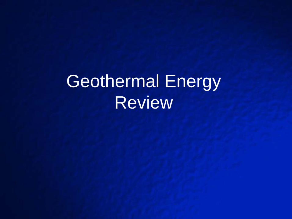
Breakdown of Global Geothermal Production By
country
Chart: Marin Katusa, Chief Investment Strategist, Casey Research Group

Types of Geothermal Energy Resources:
Volcanic Geothermal Systems (e.g. Los Azufres, Mexico)
Hydrothermal Systems: Basin and Range systems
Geopresurized Systems
Enhanced Geothermal Systems
-Conduction-Dominated Systems-Sedimentary Systems-Basement Systems
After Balckwell et al., 2006.
Geopressured-Geothermal(GPGT)
High pressure (1000-4000 psi), temperature(250-400oF), salinity (~85% NaCl) and gas content (20−100 scf/bbl )
Found at depths greater than 10,000 feet
They have the potential to produce thermal energy from the pressurizedhot water, but also hydraulic energy, by virtue of the very high pressure, and methane gas.
Geopressured reservoirs are deep reservoirs (4–6 km) in large sedimentary basins that contain pressurised hot water. This water remained trapped at the time of deposition of the sediment.
They are characterized by:

Geothermal Energy Association
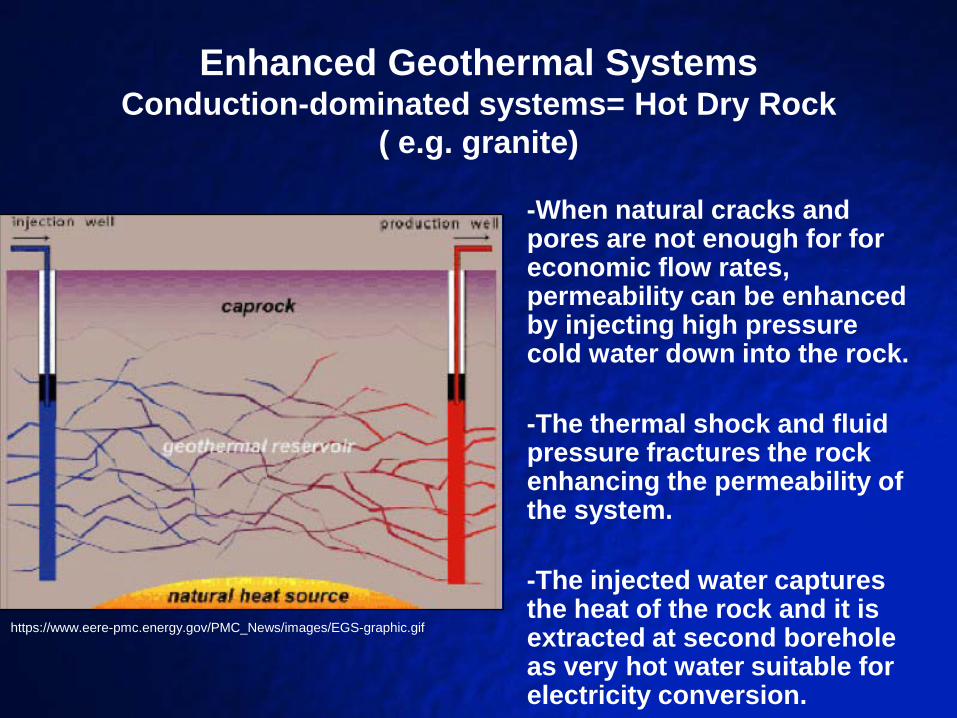
Enhanced Geothermal SystemsConduction-dominated systems= Hot Dry Rock
( e.g. granite)
-When natural cracks and pores are not enough for for economic flow rates, permeability can be enhanced by injecting high pressure cold water down into the rock.
-The thermal shock and fluid pressure fractures the rock enhancing the permeability of the system.
-The injected water captures the heat of the rock and it is extracted at second borehole as very hot water suitable for electricity conversion.
https://www.eere-pmc.energy.gov/PMC_News/images/EGS-graphic.gif

• Similar to hot dry rock (conduction-dominated systems) but different rocks and depths.
• Sedimentary and basement rocks of limited permeability
• Water can be injected in a controlled fracture setting
• Heat is transferred to the injected water. This water can be withdrawn in other wells for electrical energy generation.
Enhanced Geothermal SystemsSedimentary and Basement types

Types of Geothermal Exploitation

Types of Geothermal Exploitation
1. Direct Use-A. Municipal/Agricultural Direct Heating
B. Groundsource Heat Pumps: Basic Heat Exchange
www.nyserda.org

Geothermal Electricity ProductionTraditional Production: (Four Basic Types)
A. Flash Steam Power: Water Injection, Steam Production, Vapor-Brine Separation, Turbine Generation, Vapor Condensation, Condensate Reinjection.
Applied to Geothermal Fields > 150°C
Digtheheat.com

Geothermal Electricity Production
Traditional Production: B. Dry Steam Power: Naturally Produced Vapor (No Separation Req.)
Digtheheat.com
Geothermal Electricity Production
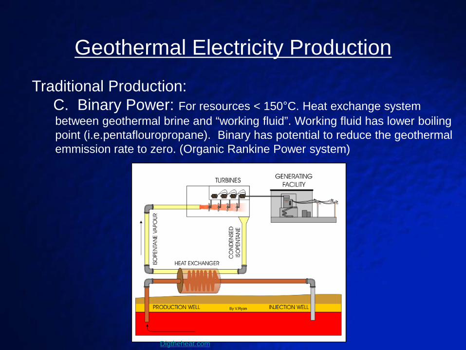
Traditional Production: C. Binary Power: For resources < 150°C. Heat exchange system between geothermal brine and “working fluid”. Working fluid has lower boiling point (i.e.pentaflouropropane). Binary has potential to reduce the geothermal emmission rate to zero. (Organic Rankine Power system)
Digtheheat.com
Examples of secondary fluids: butane, isobutane, freon, ammonia (Kalina Cycle), carbon dioxide
The choice of the secondary gas depends on the inlet temperature and the inlet pressure. Each gas has a different net power output depending on these parameters (Dai et al., 2009).
Binary Power continued…

Geothermal Electricity Production
Traditional Production: D. Flash-Binary Power: Combination System.
Two units: Vapor-Fluid separation for first plant. Lower temperature condensed fluid used in second binary plant.
http://www.enex.is/lisalib/getfile.aspx?itemid=2509
Berlin Geothermal
Field, El Salvador
Enhanced Geothermal System Potential in the United States


Blackwell, Negraru, and Richards, 2006.

Blackwell, Negraru, and Richards, 2006.

Blackwell, Negraru, and Richards, 2006.

Enhanced Geothermal Systems
2006 MIT Report
Positive Aspects:
United States consumes approx 100 EJ/year (1 EJ = 1018
joules). EGS provides estimated 14 EJ/year potential.
EGS can potentially be developed by utilizing abandoned wells within depleted hydrocarbon reservoirs.
Built upon traditional oil and gas production methods (Drilling, Hydrofracturing, etc.)
Reliable, Low Emissions
Potential Negative Aspects:
Limited by water accessibility in arid regions.
Increased seismic risk potential with injection of water (Basil Field, Switzerland)
> 5000 ft Drill Depths (western states)
Enhanced Geothermal Systems…

EGS in the United States
Coso Geothermal Project•Coso volcanic field, located 100 miles North of Los Angeles
•At < 2 km depth, temperatures reach 200 - 238ºC
•EGS via re-fracturing known reservoirs
•Since initial production in 1987, currently over 100 wells drilled
•Currently produces 270 MWe
•Operated by Caithness Energy, LLC
(From Geothermal Resources Council)

EGS in the United States
The Geysers, California• Located 20 miles North of San Francisco
• Worlds Largest Dry Stream Field - Selected for site EGS testing
• Peak production in 1987
• EGS installation in 2001 (DOE Report, 2001)
• EGS- Injection of municipal wastewater at depth 7,000-10,00 ft.
• Injection Rate of 11 million gpd
• (Renner, J.L., INELL)
• Total field produces approximately 900 Mwe (Geothermal Energy
Association)

Large EGS Developments
Cooper Basin, Austrailia •EGS with granitic basement
•Potential of 5-10 GWe
•Currently in development
•October 2003: Injection well
Habenero-1 was drilled to 4,421 m
•Placed in proximity to historic oil
exploration well ( McLeod-1)
Based upon MIT Report , 2006

EGS: Cooper Basin, Austrailia
• Bottom Hole Temperature : 250 C
• Pressures : 5,000 psi above hydrostatic
• Second Injection well (Habenero-2) was drilled to
intersect fractures stimulated from Habenero-1
• 4 km2 reservoir

Geothermal Applications for Oil and Gas
• Power generation using co-produced fluids
• Conceptual Model for heat extraction within oil and gas wells.
• Thermal Enhanced Oil Recovery
Power Generation Using Co-produced Fluid
• Department of Energy-Ormat Technologies (2005)• Goal: Electicity generation from hot water produced
from Oil/Gas wells.• Development of a mobile Organic Rankine Cycle
generator• Field Test: Rocky Mountain Testing Facility
(Casper, WY)
(Society of Petroleum Engineers, 2008)
Power Generation Using Co-produced Fluid….
• Power Generation up to 250 kW• Air Cooled Binary System-Highly Mobile• Isobutane as secondary fluid.• Electricity produced can be used for on-site power,
use even sold.• Condensed water can be reinjected to reservoir.

Coproduction in the Teapot Dome Oil Field Ormat ORC Testing (Wyoming)
• ORC influent was taken from
stripper wells at 170ºF.
• Effluent water reinjected into
reservoir at 152ºF.
• 132 kW Net Output.
• 190ºF is expected to produce
230kW.
• 5,000 MW potential from US
oilfields.
(Society of Petroleum Engineers, 2008) (Society of Petroleum Engineers, 2008)
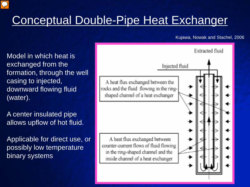
Conceptual Double-Pipe Heat Exchanger
Model in which heat is exchanged from the formation, through the well casing to injected, downward flowing fluid (water).
A center insulated pipe allows upflow of hot fluid.
Applicable for direct use, or possibly low temperature binary systems
Kujawa, Nowak and Stachel, 2006
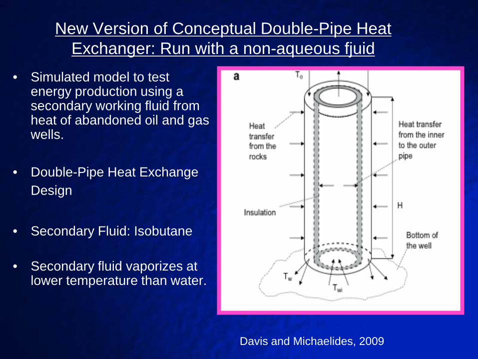
New Version of Conceptual Double-Pipe Heat Exchanger: Run with a non-aqueous fjuid
• Simulated model to test energy production using a secondary working fluid from heat of abandoned oil and gas wells.
• Double-Pipe Heat Exchange Design
• Secondary Fluid: Isobutane
• Secondary fluid vaporizes at lower temperature than water.
Davis and Michaelides, 2009
The power produced by double-pipe heat exchanger depends on:
• The down-hole temperature
• The injection pressure and injection velocity
• The geometric characteristics of the pipe such as: depth of the well, inner and outer pipe radius, and thickness of the inner pipe (insulation layer).
• The properties of the fluid exchanging heat (Net Power Output depends on the type of fluid, pressure and temperature).
• It should depend on the thermal properties of the surrounding rock and water. It is assumed groundwater velocities are low.
Conceptual Double-Pipe Heat Exchanger...
Advantages of the double-pipe heat exchanger:
• Study indicates well potential is 2-3 MW with a well depth of 3,000 m and bottom-hole temp of 450°F (Typical South Texas well)
• Power is not intermittent as with other renewable energy sources.
• The need for an external pump and heat exchanger is eliminated (the heat exchanger in the Rankine Cycle is the well itself).
• Minimum flux of green house gases since the secondary fluid is recycled through the system.
• Great potential for the many abandoned deep wells in the US.

Some concerns abou the double-pipe exchangers:
• Large volume of secondary fluid needed, depending on well dimensions.
• Leaks between the two pipes should be eliminated.
• Need to minimize exchange heat and fluid between the two concentric pipes.

Geothermal Techniques for Enhanced Oil Recovery

Enhanced Oil Recovery(EOR)
•Third stage production for oil reservoirs
•Three Main Types: 1. Chemical Flooding (Alkaline or Micellular Polymers)2. Miscible Displacement (CO2 Injection)3. Thermal: Steam Flood or In-situ combustion

Steam Flooding1. Heavier steam injection than Cyclic Steam2. Typically recovers 50% of OOIP (Original Oil In Place).3. Reduces viscosity and drives oil towards producing wells.
Thermal Enhanced Oil Recovery(TEOR)
Typical Enhanced Oil Recovery System, SNF-Floerger.com

Imperial Oil, 2001
Cyclic Steam Simulation
1. 3 Stages: Injection, Soaking
and Production.
2. Performed through same well.
3. Typically recovers 20% of
OOIP (Original Oil In Place).

Steamflood PerformanceKern River Oil Field
•Located in Kern County, CA
•Approx 10 miles north of Bakersfield
•22.24 km2 area in production since 1912
•Over 9,000 historic wells drilled.
•About 760 active wells 2006
California Department of Conservation

Steamflood PerformanceKern River Oil Field
• Heavy Crude of 14 API Gravity
• Average oil bearing depths of 2,300 ft
• Steamflooding in Kern will accounts for nearly 80% of total barrels recovered (Chevron, 2006).

Role of Steamflood Technology in Increasing Heavy Oil Production and Reserves.Chevron, 2006
Why do we need to plan for the exploitation of new sources of energy?
According to the Energy Information Administration (EIA, 2006):
U.S. generating capacity has increased more than 40% in the past 10 years to more than 1 TWe. However, this increase resulted from adding fossil fuel generation plants.
In the next 15 to 25 years about 50 GWe or more of coalfired capacity will be retired due to environmental concerns.
In the same period, 40 GWe or more of nuclear capacity will be decommissioned.

Conclusions• Global research and development of Enhanced
Geothermal Systems indicates a broader geothermal exploitation area and large scale amount of potential energy ( Escpecially in the United States).
• Large amounts of abandoned oil and gas wells within depleted reservoirs may prove to be feasible locations for lower cost development of EGS and other technology.
• On-site power generation using co-produced fluids has shown great potential to reduce production costs and maximize energy recovered. (Ormat’s ORC)

Conclusions
• Conceptual geothermal recovery systems (e.g. Double-pipe Heat Exchange) may be applied to abandoned production wells for low temperature extract and direct use.
• Thermal Enhanced Oil Recovery methods such as steamflooding, have shown to be highly effective in low viscosity oil reservoirs.

Thank you!!
Haynesville Shale
Blackwell et. al., 2008
•Average Depth:10,500 to 13,500 ft.•Average Treating Pressures :6,000 to 15,000 psi•Average Temperature: 310F/168C

Natural Energy Engine:• Created by Deluge Inc.• Tested in 2005 at the Rocky Mountain Oil Testing Center• 335 hp Hydraulic System• Operates with hot water only.
• How it works:• Liquefied CO2 as working fluid to drive a piston.• Hot water is extracted from well vi co-produced fluids• Hot water influent passes through heat exchanger• CO2 contracts w/ cool water through heat exchanger • Optimum influent temperature is 185°F• Optimum temperature differential is 100°F (e.g. 185°F to 85°F) • Capable to pump heavy crude at depths of 400-1600 ft.• Oil pumped to on-site storage tank.
Geothermally Driven Pumps
(Delugeinc.com)