Embed Size (px)
Citation preview
Processes and Methods forIntegrated Modular Avionics
Presentation at USA - EU WorkshopParis, July 7th 2005
Presented by
Gert DÖHMENAIRBUS Germany

Page 2©AI
RBU
S D
EUTS
CH
LAN
D G
mbH
. Alle
Rec
hte
vorb
ehal
ten.
Ver
traul
iche
s un
d ge
schü
tzte
s D
okum
ent.
Integrated Modular Avionics (IMA)
AALRU A
LRU BBB Airborne
Functions
IntegratedAvionics
ConventionalAvionics
LRU CC
LRM 1LRM 2
Identical Hardware & Kernel Software used for different
Airborne Functions in Flight Control & Utility Functions
Page 3©AI
RBU
S D
EUTS
CH
LAN
D G
mbH
. Alle
Rec
hte
vorb
ehal
ten.
Ver
traul
iche
s un
d ge
schü
tzte
s D
okum
ent.
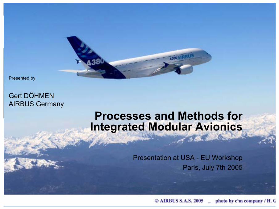
Targeted IMA Advantages
•• Reduction of Weight / Volume / Power consumption of Reduction of Weight / Volume / Power consumption of the Avionicsthe Avionics
•• Reduction of material stocks within Airline Maintenance Reduction of material stocks within Airline Maintenance CentersCenters
•• Reduction of cost for VersionsReduction of cost for Versions--Upgrades (core HW & Upgrades (core HW & SW)SW)
•• Reduction of cost for functional enhancementsReduction of cost for functional enhancements•• Reduction of cost through the emerging market of open Reduction of cost through the emerging market of open
standardsstandards

Page 4©AI
RBU
S D
EUTS
CH
LAN
D G
mbH
. Alle
Rec
hte
vorb
ehal
ten.
Ver
traul
iche
s un
d ge
schü
tzte
s D
okum
ent.
IMA Concept - LRU / LRM based Architecture
AFDX Switch
LRU
AFDX interface
Static cabling configuration1 new link = AFDX switch configuration table update
LRMmodule
AFDX link
LRU6
ARINC 429 world IMA world
LRU5
LRU2
LRU1
LRU7
ARINC 429 interface
LRU4
1 new link = 1 new cable
ARINC 429 link
CPIOM
CPIOM
IOM
LRU
AFDX Switch
AFDX E/S

Page 5©AI
RBU
S D
EUTS
CH
LAN
D G
mbH
. Alle
Rec
hte
vorb
ehal
ten.
Ver
traul
iche
s un
d ge
schü
tzte
s D
okum
ent.
ADCN Network Architecture - Functional DomainsWARNING: old obsolete architecture for functional domain description only!
Engines
Cabin
Fuel&LGEnergy
Cockpit
FlightControl
AESU1
EEC1
EEC2
FCSC1COM MON
FCSC2FCGC2
FCGC3SFCC2
COM MONCOM MONSFCC1
FCGC1
ADIRU1
ADIRU3
ADIRU2
FM3
FM2FM1
FW2FCDC2
FW1FCDC1
AESU2
ACR2 opt
SCI
L1 L2 R2 R1
C2 R3
C1
SW13
IOM
ELMCBMSB24
ELMCBMSB24
FuelCOM MON
FuelLG,TP&BSCOM MON
CIDS
CPIOM-B-1&2
CIDS
CPIOM-A-3&4CPIOM-B-3&4
IRDC
COM MONLG,TP&BS
COM MON
COM MON COM MON COM MON
IOM
ACR1
SCI
CPIOM-A-1&2
PESC
SPDB
IPCU
SPDB
VSCPWCU
IRDC
DSMC1&2 DSMC3
ext lightsctrl
IPCU
ECB
HSMAIC?
HSMAIC?
COM MON FCSC3 TBCCOM MON
L3
IOMIOM CDAM
ATC1 ATC2
A
AB
B
EEC3
EEC4AB
BA
S_2_1
S_3_1
S_4_1
S_1_1
S_3_2
S_4_2
S_1_2
S_2_2
S_1_3

Page 6©AI
RBU
S D
EUTS
CH
LAN
D G
mbH
. Alle
Rec
hte
vorb
ehal
ten.
Ver
traul
iche
s un
d ge
schü
tzte
s D
okum
ent.
Flow Separation Concept
VL1
VL2
VL3
Physical LinkLogical
representationof a Virtual Link
Ethernet controller
Switching FabricSWITCH
Transmit MACTX
TXRX TXRX TXRX
Appl. 1
Appl. 2
Appl. 3
Physical Link
Virtual Links
End-System 1
End-System 1
End-System 2
End-System 3
End-System 4
End-
Syst
em
3
TX RX
End-
Syst
em
3
TX RX
End-
Syst
em
3
TX RX
Receive MAC RX
The Virtual Link ConceptThe Virtual Link Concept
VL2

Page 7©AI
RBU
S D
EUTS
CH
LAN
D G
mbH
. Alle
Rec
hte
vorb
ehal
ten.
Ver
traul
iche
s un
d ge
schü
tzte
s D
okum
ent.
LRM / CPIOM Hardware
Four electronic boards :Four electronic boards :- One CPU board- One CPU board- One Power supply and I/O board- One Power supply and I/O board- Two I/O boards- Two I/O boards
ARINC 600 SIZE 2ARINC 600 SIZE 2ConnectorConnector
BackplaneBackplane
SIS module connectorSIS module connector
PCI interconectionPCI interconectionboardboard
• ARINC 600, 3 MCU• Approximately 4 kg• Powered by 28VDC (some on ESS bus)• ARINC 600 conn., 368 pins + 2 QUADRAX• Hardware pin programming identifies domain, location,
side, aircraft (MAC and IP addressing on Aircraft Data Communication Network (ADCN))

Page 8©AI
RBU
S D
EUTS
CH
LAN
D G
mbH
. Alle
Rec
hte
vorb
ehal
ten.
Ver
traul
iche
s un
d ge
schü
tzte
s D
okum
ent.
Building blocks of an Integrated CPIOM
Inst
rum
enta
tion
Ser
vice
Dat
aloa
ding
Operating System
Hardware
Memory ManagementSchedulingData I/O, Communication
Application Programming Interface
ConfigurationTable
Res
ourc
e B
ITE
MIB
- SN
MP
Mon
itorin
g User SystemApplication n
User SystemApplication 1
User SystemApplication 2
...AFDX CommunicationARINC CommunicationCAN CommunicationAnalogue SignalsDiscrete Signals

Page 9©AI
RBU
S D
EUTS
CH
LAN
D G
mbH
. Alle
Rec
hte
vorb
ehal
ten.
Ver
traul
iche
s un
d ge
schü
tzte
s D
okum
ent.
IMA Configuration Process Aspects
• Classification of Configuration Parameter (Module, Global, Local).
• Hardware/OS specific configuration parameter.• Manual assignment of resources supported by databases.• Automated tool-chain to produce the load.
Function Supplier 3
Function Supplier 1
Function Supplier 2
System Depart. 3
System Depart. 1
System Depart. 2Module Integrator
ADCN & IMA
Module Supplier
Airbus
A380: 7 Module types; Up to 4 redundant Modules; 22 Physical Modules
Information & Data Flowfor one Module Type

Page 10©AI
RBU
S D
EUTS
CH
LAN
D G
mbH
. Alle
Rec
hte
vorb
ehal
ten.
Ver
traul
iche
s un
d ge
schü
tzte
s D
okum
ent.
Visions for IMA
Processes & Methods

Page 11©AI
RBU
S D
EUTS
CH
LAN
D G
mbH
. Alle
Rec
hte
vorb
ehal
ten.
Ver
traul
iche
s un
d ge
schü
tzte
s D
okum
ent.
Configuration based on System Model
• Configuration bound to System Description Language• Support of different Layer (e.g. Application, OS, Hardware)• Decoration of Abstract Syntax Tree with configuration data
CPIOM
KERNELBOOT
I/O(discrete,
analog)
AFDX
1
CAN
DRV_MGR
ARINC 429
MODULE KERNEL
PARTITION PARTITIONMANAGEMENT
SERVICES
0..*
API
Scheduler
PARTITION A Queuing Com 001 PARTITION B
reset reset
OUT P1 P2 IN
• Declaration of dependencies between parameter on the same or adjacent layer.

Page 12©AI
RBU
S D
EUTS
CH
LAN
D G
mbH
. Alle
Rec
hte
vorb
ehal
ten.
Ver
traul
iche
s un
d ge
schü
tzte
s D
okum
ent.
Component-based System Development
• Concept of building up the system architecture from exchangeable (heterogeneous) components.
• Components are enriched with functional and non-functional aspects as “Heterogeneous Rich Components” (HRC).
• Their characteristics can be assessed on the basis of those aspects.
Assumed
From/by lower design layers
from neighbors
Promised
From/by higher design layers
to neighbors
EL
FL
SL
HL
• Design-space exploration is used to find a semi-optimal mapping of applications to LRMs under multi-dimensional constraints.

Page 13©AI
RBU
S D
EUTS
CH
LAN
D G
mbH
. Alle
Rec
hte
vorb
ehal
ten.
Ver
traul
iche
s un
d ge
schü
tzte
s D
okum
ent.
Improvement of the Development Process
• Ubiquitous seamless model-based design accesshiding heterogeneity and semantic diversity of representations and methods, andproviding a design-centric access to all design activities.
• During all design phases, process steps must be guided by an estimation how far overall requirements (e.g. safety, costs) are fulfilled. This “speculative” design can be based on HRC analysis methods.
• High flexibility and robustness with respect to late changes and overlapping design activities.

Page 14©AI
RBU
S D
EUTS
CH
LAN
D G
mbH
. Alle
Rec
hte
vorb
ehal
ten.
Ver
traul
iche
s un
d ge
schü
tzte
s D
okum
ent.
From Structural to Analytical Redundancy
• Identical Hardware & Kernel Software is the prerequisite for a flexible allocation (reconfiguration) of applications.
• The amount of Structural Redundancy (and thus number of LRM) can be reduced by the use of Analytical Redundancy.
• Analytical Redundancy requests design-space exploration with safety constraints.
• The Analytical Redundancy has to respect certification aspects.

Page 15©AI
RBU
S D
EUTS
CH
LAN
D G
mbH
. Alle
Rec
hte
vorb
ehal
ten.
Ver
traul
iche
s un
d ge
schü
tzte
s D
okum
ent.
Dieses Dokument und alle darin enthaltenen Informationen sind das alleinige Eigentum von AIRBUS DEUTSCHLAND GmbH. Die Zustellung dieses Dokumentes oder die Offenlegung seines Inhalts begründen keine Rechte am geistigen Eigentum. Dieses Dokument darf ohne die ausdrückliche schriftliche Genehmigung von AIRBUS DEUTSCHLAND GmbH nicht vervielfältigt oder einem Dritten gegenüber enthüllt werden. Dieses Dokument und sein Inhalt dürfen nur zu bestimmungsgemäßen Zwecken verwendet werden.
Die in diesem Dokument gemachten Aussagen stellen kein Angebot dar. Sie wurden auf der Grundlage der aufgeführten Annahmen und in gutem Glauben gemacht. Wenn die zugehörigen Begründungen für diese Aussagen nicht angegeben sind, ist AIRBUS DEUTSCHLAND GmbH gern bereit, deren Grundlage zu erläutern.