Embed Size (px)
Citation preview

gesis®LON R-56/0 (RC)… EnOcean® LON Gateway
Manual Product and Object Description Doc. no. BA000580 Date: 6/2009 (Rev. A)
© 2008 Wieland Electric GmbH

This document is protected by copyright. The rights established by this remain with Wie-
land Electric GmbH. Reproduction of this document whether in whole or in part is only
permitted within the copyright provisions. Modifications or abridgements of the document
without express written permission of Wieland Electric GmbH are not permitted.
All brands mentioned and when indicated protected by third parties in this document are
subject to, as such unreservedly, the respective valid legal requirements and right of own-
ership of the respective registered owner.
Naming alone does not imply that the trade mark is not protected by third party rights!
Revision Listings
Document BA000579
Revision Date Author / editor
A (first version) 12.2.2009 Th. Nieborg/Th. Kluck

Contents
Wieland Electric | BA000580 | 6/2009 (Rev. A) 3
Contents
1 About This Operating Manual.......................................................................... 6 1.1 General Information ................................................................................................... 6 1.2 Symbols and Notation Used ...................................................................................... 6 1.3 Proper Use ................................................................................................................. 7 1.4 Selecting Personnel and Personnel Qualifications..................................................... 8 1.5 Tests and Repairs....................................................................................................... 8 1.6 Hazards due to Electrical Energy ............................................................................... 8 2 The LON Bus System....................................................................................... 9 2.1 Technology................................................................................................................. 9 2.2 Topology .................................................................................................................... 9 2.3 Addressing ................................................................................................................. 9 2.4 Communication........................................................................................................ 10 2.5 Software................................................................................................................... 10 2.6 Installation of the LNS Plug-In ................................................................................. 10 2.6.1 System requirements ............................................................................................... 10 2.6.2 Device and parameter description files (SDRF, UDRF)............................................ 10 2.6.3 Availability ................................................................................................................ 10 2.6.4 Installation................................................................................................................ 11 2.6.5 Installation routine ................................................................................................... 11 2.6.6 Registration in the Windows registry ...................................................................... 11 3 gesis LON R: System Overview ..................................................................... 12 3.1 Selection of an Application Program ....................................................................... 12 3.2 Modules With No Mounting Feet ............................................................................ 12 3.3 Place of Installation .................................................................................................. 12 4 gesis LON R-56/0 (RC) ................................................................................... 13 4.1 Device Description ................................................................................................... 13 4.2 Function ................................................................................................................... 13 4.3 Dimensions, Connections and Function Elements .................................................. 14 4.4 Terminal Assignment ............................................................................................... 15 4.5 Technical Data.......................................................................................................... 16 4.6 Installation................................................................................................................ 17 4.6.1 Assembly (83.020.0320.0) ....................................................................................... 17 4.6.2 Dismantling (83.020.0320.0).................................................................................... 17 4.6.3 Replacing modules (83.020.0320.1) ........................................................................ 17 4.7 Accessories .............................................................................................................. 17 5 Installation of the LNS Plug-In....................................................................... 18 6 Teach-in of the sensors ................................................................................. 19 7 Parameterisation ........................................................................................... 20 7.1 General ..................................................................................................................... 20 7.2 NodeObject .............................................................................................................. 21 7.3 EnOcean-Objekt ....................................................................................................... 22 7.4 Panel......................................................................................................................... 24 7.5 Parameterisation of individual sensors .................................................................... 25 7.5.1 Button / Switch transmission element..................................................................... 26 7.5.1.1 Switch / Button transmission element (Switch / Button value).............................. 26 7.5.1.2 Switch / Button transmission element (presence information) .............................. 29

Contents
4 Wieland Electric | BA000580 | 6/2009 (Rev. A)
7.5.1.3 Switch / Button transmission element (scene number) ......................................... 30 7.5.2 Window contact ....................................................................................................... 31 7.5.3 1-byte sensor ............................................................................................................ 31 7.5.3.1 1-byte sensor (temperature value)........................................................................... 32 7.5.3.2 1-byte sensor (brightness value) .............................................................................. 33 7.5.3.3 1-byte sensor (other)................................................................................................. 33 7.5.4 4-byte sensor ............................................................................................................ 34 7.5.4.1 4-byte sensor (temperature value)........................................................................... 34 7.5.4.2 4-byte sensor (brightness value) .............................................................................. 35 7.5.4.3 4-byte sensor (other)................................................................................................. 35 7.5.5 Alarm transmitter...................................................................................................... 35 7.5.6 Window handle ........................................................................................................ 36 8 Operation....................................................................................................... 38 8.1 Teach-in of transmitters (Learn; e.g. button)............................................................ 38 8.2 Deletion of assignments (Clear) ............................................................................... 38 8.2.1 Variant 1: Delete a single ID ..................................................................................... 38 8.2.2 Variant 2: Delete all IDs from one channel............................................................... 38 8.2.3 Variant 3: Delete all IDs from the gateway (restore factory settings) ...................... 39 9 Power supply gesis EIB RM-PS ..................................................................... 40 9.1 Device Description ................................................................................................... 40 9.2 Function.................................................................................................................... 40 9.3 Dimensions, Connections and Function Elements................................................... 41 9.4 Terminal Assignment................................................................................................ 41 9.5 Technical Data .......................................................................................................... 41 9.6 Installation ................................................................................................................ 42 9.6.1 Assembly (83.020.0401.0)........................................................................................ 42 9.6.2 Disassembly (83.020.0401.0) ................................................................................... 42 9.6.3 Replacing modules (83.020.0401.1)......................................................................... 43 10 Power supply gesis RM-PS 12/5.................................................................... 44 10.1 Device Description ................................................................................................... 44 10.2 Function.................................................................................................................... 44 10.3 Dimensions, Connections and Function Elements................................................... 45 10.4 Terminal Assignment:............................................................................................... 45 10.5 Technical Data .......................................................................................................... 46 10.6 Installation ................................................................................................................ 47 10.6.1 Assembly (83.020.0421.0)........................................................................................ 47 10.6.2 Disassembly (83.020.0421.0) ................................................................................... 47 10.6.3 Replacing modules (83.020.0421.1)......................................................................... 47

About This Operating Manual
Wieland Electric | BA000580 | 6/2009 (Rev. A) 5
Dear customer,
Congratulations on purchasing your new components of the gesis LON R building installa-
tion system. You are now the owner of a product with the LON technology which provides
you with a user-friendly means of dealing with numerous building control tasks.
Please familiarise yourself with the descriptions in this manual. It will provide you with
all the information and assistance required for faultless operation of your gesis system.
Should you have additional questions or require further assistance, please contact our
team of specialists using the contact information below and they will be happy to help
you.
Wieland Electric GmbH Brennerstraße 10-14 96052 Bamberg, Germany
Technical customer service hotline (for technical issues concerning accessories, functions,
product features and possible applications):
Tel.: +49 (0) 9 51 / 93 24-9 96 Fax: +49 (0) 9 51 / 93 26-9 96 Email: [email protected]
Sales hotline (for information about availability, lead times and prices): Tel.: +49 (0) 9 51 / 93 24-9 90 Email: [email protected]

About This Operating Manual
6 Wieland Electric | BA000580 | 6/2009 (Rev. A)
1 About This Operating Manual
1.1 General Information
This operating manual will provide you with support for installing and parameterising gesis
LON R modules. In it, you will find information about how devices are programmed, con-
figured and parameterised.
This operating manual contains the information required for proper usage of the prod-
uct it describes. It describes the gesis LON R component, its technical features, conditions
of use, boundary conditions and parameterisation. Installation and connection with the
gesis CON connector system are described in the document entitled "System Handling
Information" (item no. 0060.2), which is available separately.
gesis systems must only be installed by trained personnel and the applicable regula-
tions observed while doing so. For this reason, the gesis LON R system manual is aimed
at:
• Persons responsible for configuring, parameterising and activating LON systems
• System integrators
• Electricians
Specific prerequisites are:
• Basic knowledge of LON bus technology
• Basic knowledge of building installation systems
• Programming knowledge relating to LON objects
1.2 Symbols and Notation Used
The following are used in this operating manual:
A notice informs you about special features of a device or a software function. "Notice"
also indicates information that is directly or indirectly related to the safety of personnel or
property. It is not used for hazards or hazardous situations.
The names of software menus, submenus, options and commands, selection fields and
windows are shown in bold. Example: Click on Edit in the File menu.
Keys and key combinations are shown in UPPERCASE. Key combinations, i.e. keys which
have to be pressed simultaneously, are linked with a "+". Keys which have to be pressed
one after the other are linked with a "–". Example: Press CTRL+ALT+DEL (simultaneously).
Press F12–2 (one after the other). The naming of the keys refers to standard keyboards
which are labelled in the language of the user country. It is possible you are using a key-
board with other key labelling, e.g. in the German language.
Objects, variables, program code and parameters are identified with typewriter font.
NOTICE
Menus and Commands
Keys
Objects and variables

About This Operating Manual
Wieland Electric | BA000580 | 6/2009 (Rev. A) 7
This operating manual uses various safety notices that are assigned according to the sever-
ity of a potential hazard:
"Danger" indicates an imminently hazardous situation or state which, if not avoided, will
result in serious injuries or death. The use of "Danger" is limited to the most extreme situa-
tions.
"Warning" indicates a potentially hazardous situation or state which, if not avoided, canre-
sult in serious injuries or death.
"Caution" indicates a potentially hazardous situation or state which, if not avoided, can
result in minor or moderate injuries. "Caution" is also used to warn against unsafe prac-
tices or obvious misuse, as well as for situations which may result in material damage or
personal injury.
"Danger" or "Warning" are basically used for cases which present a risk to life or limb.
Damage to property only falls into these categories if there is also a risk of personal injury
that corresponds to these levels.
1.3 Proper Use
• Electrical installations, commissioning and maintenance work, as well as configuring and
programming work, must only be performed by qualified electricians with relevant acci-
dent prevention training, and in compliance with the applicable regulations.
• Safety precautions and safety devices must comply with the applicable regulations.
• Compliance with the required regulations is achieved when the devices are correctly
processed in order to create an end product.
• Damaged products must neither be installed nor put into operation.
• On account of the class and degree of protection, all devices must be installed in a gesis
distribution box (gesis RAN) or similar housing.
• Due to their holding equipment, devices without locking feet may only be installed in a
gesis RAN housing provided by Wieland Electric.
• A power supply from the gesis RM series of devices is required for operating the basic
module. If a power supply other than the gesis product intended for this purpose is used,
Wieland Electric GmbH cannot guarantee that faultless operation will take place.
• When looping through the voltages, the maximum current of 16 A must not be ex-
ceeded.
The control system must only be used when in proper working condition, as well as ac-
cording to its prescribed usage, with due regard given to safety, awareness of any hazards
and following the instructions contained in the operating manual. Reliable and safe opera-
tion requires proper transport, storage and installation, as well as careful operation. In
particular, safety-related faults must be rectified immediately by a professional.
The control systems are exclusively intended for controlling building equipment. Other
applications, or use beyond this scope, are considered to be improper. The manufacturer
assumes no responsibility for any damage resulting from usage of this nature.
In order to use the control systems as prescribed, the instructions outlined in this oper-
ating manual must be followed for mechanical and electrical installation procedures, as
well as for commissioning and operation of the systems.
DANGER
WARNING
CAUTION
WARNING
NOTICE

About This Operating Manual
8 Wieland Electric | BA000580 | 6/2009 (Rev. A)
1.4 Selecting Personnel and Personnel Qualifications
• Electrical installations, commissioning and maintenance work, as well and configuring
and programming work, must only be performed by trained, qualified electricians with
relevant accident prevention training, and in compliance with the applicable regulations.
• Configuring and programming personnel must be familiar with the safety concepts in-
volved in building installation technology.
• Operating personnel must be trained in handling the control system and familiar with the
operating instructions.
• Installation, commissioning and maintenance personnel must have a training back-
ground which authorises them to carry out work on the control system.
1.5 Tests and Repairs
When measurement or testing procedures are being performed on the active device, the
specifications and implementation guidelines of the relevant accident prevention regula-
tions must be observed. Only suitable tools may be used for this.
Repairs to control components must only be carried out by the manufacturer.
Unauthorised opening and improper intervention or repairs can result in material damage
or bodily harm.
In the event of a fault, send devices back to:
Wieland Electric GmbH
Abteilung (Department) TQM 3
Brennerstraße 10-14
96052 Bamberg, Germany
1.6 Hazards due to Electrical Energy
The user must ensure that unauthorised and improper interventions are prevented. Per-
sonnel must be familiar with all sources of hazards and all procedures involved for the
commissioning. This includes both data contained in the gesis "System Handling Informa-
tion" document (item no. 0060.2) and device packaging inserts as well as the relevant
content from this manual.
WARNING
CAUTION

The LON Bus System
Wieland Electric | BA000580 | 6/2009 (Rev. A) 9
2 The LON Bus System
2.1 Technology
LON systems are based on an "installation bus": this refers to the cable which links all the
devices that are connected and transfers signals between all the bus nodes.
LON is a decentralised bus system. A central unit is not required since each node (bus
device) has its own intelligence. Software is used to download all the required parameters
to the individual devices via the bus. Different transfer media are available within the LON.
All Wieland LON devices use twisted pair (TP) 2-wire bus technology and a TP/FT-10
transceiver with external power supply. A separate cable is used, which is laid when the
standard electrical installation takes place and provides the medium for transporting status
messages or switching commands for communication purposes. In larger LON systems, the subnets are logically linked and electrically isolated from each other by means of routers. The routers ensure that the telegram load on the coupled sub-nets does not become too great. They prevent telegrams that are only required in particu-lar areas from entering other areas, thereby reducing the bus load. The LON is an event-controlled bus system, which means that telegrams are only created when they are actu-ally needed.
2.2 Topology
Each bus connection represents a node, regardless of whether this is concerned with a
straightforward button or complex visualisation.
The nodes in each system are divided into sensors (e.g. buttons, temperature sensors),
actuators (e.g. switching outputs, shutter outputs) and system devices (e.g. routers, power
supplies).
The smallest unit in the LON system is a subnet. A subnet can link up to 127 nodes.
Routers enable up to 255 subnets to be connected to form a domain (a network). This
means that networks with more than 32,000 nodes in a domain can be implemented. In
the case of extremely complex installations, special couplers can be used to interconnect
several domains.
2.3 Addressing
Unique "addresses" are used for identifying and addressing specific bus nodes. The LON
system uses two address types:
Neuron ID
The Neuron ID is a 48 bit identifier that is unique worldwide (similar to an Ethernet MAC
address) and which is assigned to every LON chip during manufacture. It enables any node
to be unambiguously identified at any time. This allows separate LON networks to be
automatically combined at a later date in order to create one single network, for example.
Subnet/Node ID
The subnet/node ID is assigned to each node during commissioning. It unambiguously
defines each node. Since this address is based on the subnet structure, the bus system
itself remains clear, right up to the final extension stage. In addition, the subnet/node ID
ensures that the commissioning engineer has enough leeway to take building structures

The LON Bus System
10 Wieland Electric | BA000580 | 6/2009 (Rev. A)
into account as well. Each device can be addressed in such a way that it can easily be
assigned to existing building structures (e.g. "West building, 1st floor, North side").
2.4 Communication
The LONTALK protocol is used for communication between nodes. Logical links are cre-
ated between buttons, controllers and actuators, for example, by means of "bindings".
These links can be established within the same subnet or via multiple routers. If the latter
is the case, the required filter tables in the routers are created and stored automatically.
Special routers can also be used to interconnect individual subnets via TCP/IP links. This
allows an existing Ethernet infrastructure to serve as a backbone.
2.5 Software
A variety of software tools is available for planning, commissioning and documenting a
LON system. This means that, whatever the requirements of the project or the level of
training undergone by the commissioning engineer, there will always be an appropriate
tool.
The LNS has established itself as the common network operating system and is used by
all relevant tools. Subnet/node IDs, bindings, parameters, etc. can be defined and changed
via LNS not only for each device, but also for the system as a whole.
The manufacturers provide specific data for the devices used in the system free of
charge, in the form of application files, and input it into the LNS. As well as the standard
configuration options provided by the commissioning tools, the majority of manufacturers
also provide configuration tools (plug-ins) free of charge, which are integrated in the soft-
ware tool, to make commissioning easier. LNS plug-ins are available free of charge for all Wieland LON devices and can be used in an LNS environment of version 3 or higher.
2.6 Installation of the LNS Plug-In
2.6.1 System requirements
• PC/laptop with an LNS installation tool installed and a suitable interface for connecting to
the LON system
• LNS version 3.x or higher with all available service packs
• Standard Device Resource Files (SDRF) version 12 or higher (available free of charge at
www.lonmark.org)
2.6.2 Device and parameter description files (SDRF, UDRF)
Standard Device Resource Files (SDRF) version 12 or higher must be installed before in-stallation of the plug-in. The user-defined description files (UDRF) that are required to dis-play Wieland-specific parameters correctly are automatically copied and initialised when the Wieland plug-in is installed.
2.6.3 Availability
The Wieland LNS plug-in for the gesis LON R series of devices can be downloaded free of
charge from the downloads area of the Wieland website (www.gesis.com).
It is recommended to download the current version before each new project.

The LON Bus System
Wieland Electric | BA000580 | 6/2009 (Rev. A) 11
2.6.4 Installation
To install the plug-in, please launch the "setup.exe" file and follow the on-screen instruc-
tions.
2.6.5 Installation routine
The installation routine automatically performs all the steps required to install the plug-in,
register the Wieland parameter descriptions( UDRFs) and copy the device templates. The
following default directories within the LonWorks basic directory (usually C:\LonWorks\)
are used:
• The plug-in is installed in ..\PlugIns\Wieland Electric\WLD_GESISRC\
• The UDRFs are stored under ..\types\User\Wieland Electric\
• The device templates are stored under ..\import\Wieland Electric\
Following successful installation, a new program directory called "Plug-In for gesis LON R
Devices" is created in the Windows Start menu, which can also be used for direct access
to the manual (this document).
2.6.6 Registration in the Windows registry
The installation routine automatically enters the plug-in in the Windows registry. If the
entry is not made automatically, it must be done manually before the LNS commissioning
tool can be used. To do this, launch one instance of the plug-in directly via the Windows
Start menu and select the "Register" button. The plug-in can then be registered using the
procedure for individual LON projects, which is specific to each commissioning tool.
If the Wieland plug-in needs to be removed from the Windows registry, please launch
the plug-in directly once again via the Windows Start menu and select "Unregister".

gesis LON R: System Overview
12 Wieland Electric | BA000580 | 6/2009 (Rev. A)
3 gesis LON R: System Overview
3.1 Selection of an Application Program
This manual refers to the application program with the file name WiRcGate1x.
3.2 Modules With No Mounting Feet
In order to achieve a minimum installation height of approximately 55 mm when installing
modules in the gesis RAN pluggable distribution box, they are also manufactured without
feet. These modules are installed in the gesis RAN in the factory using special equipment.
3.3 Place of Installation
The modules must be installed in a gesis RAN or similar housing. If a gesis RAN distribu-
tion box is used, the modules are installed by Wieland and wired to gesis CON series con-
nectors. The distribution box is designed and manufactured in accordance with customer
requirements, meaning it can be adapted to almost any conditions. The system/customer-
specific planning and design of the distribution box also extends to labelling of the inputs
and outputs. External connections are established using the gesis CON connector system.
As terminal blocks, transformers and other similar devices can also be installed in these
distribution boxes, this allows complete room functions to be created and efficiently inte-
grated into the pluggable electrical installation.
gesis LON R-56/0 (RC)
Wieland Electric | BA000580 | 6/2009 (Rev. A) 13
4 gesis LON R-56/0 (RC)
4.1 Device Description
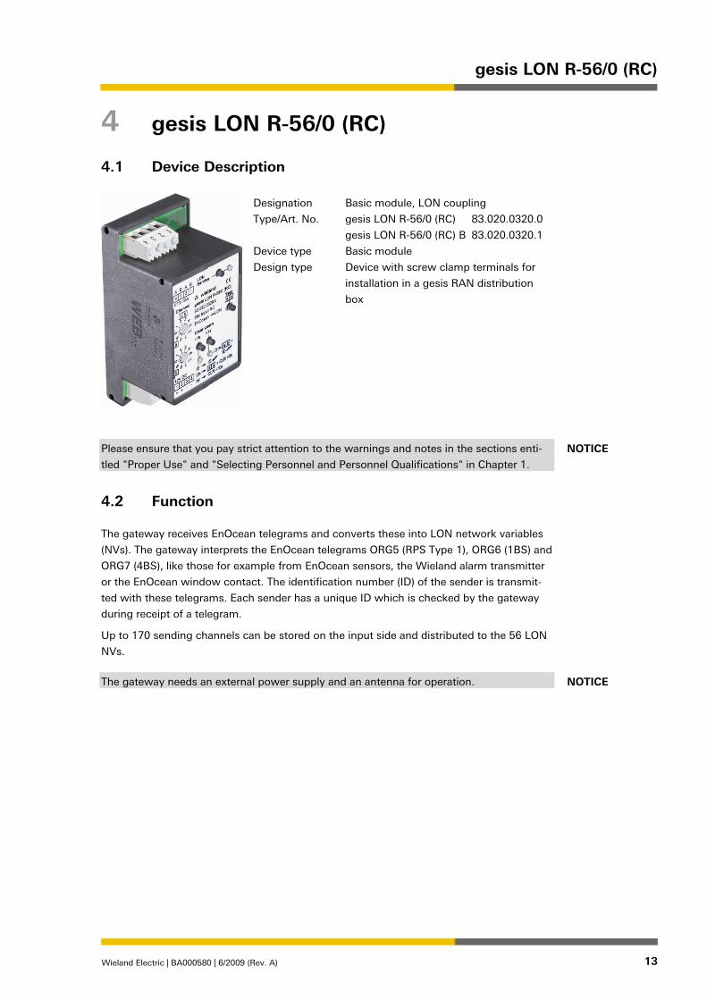
Designation
Type/Art. No.
Device type
Design type
Basic module, LON coupling
gesis LON R-56/0 (RC) 83.020.0320.0
gesis LON R-56/0 (RC) B 83.020.0320.1
Basic module
Device with screw clamp terminals for
installation in a gesis RAN distribution
box
Please ensure that you pay strict attention to the warnings and notes in the sections enti-
tled "Proper Use" and "Selecting Personnel and Personnel Qualifications" in Chapter 1.
4.2 Function
The gateway receives EnOcean telegrams and converts these into LON network variables
(NVs). The gateway interprets the EnOcean telegrams ORG5 (RPS Type 1), ORG6 (1BS) and
ORG7 (4BS), like those for example from EnOcean sensors, the Wieland alarm transmitter
or the EnOcean window contact. The identification number (ID) of the sender is transmit-
ted with these telegrams. Each sender has a unique ID which is checked by the gateway
during receipt of a telegram.
Up to 170 sending channels can be stored on the input side and distributed to the 56 LON
NVs.
The gateway needs an external power supply and an antenna for operation.
NOTICE
NOTICE

gesis LON R-56/0 (RC)
14 Wieland Electric | BA000580 | 6/2009 (Rev. A)
4.3 Dimensions, Connections and Function Elements
13
10
8
6
2
1
+
2
2
3B
4
3
-
65
56
W
1B
2
4
1
ID
11
12
7
9
5
4
3
1
2
8
a b
8
4
44
a b
ID a
a
+
2
+ - All
ID12V DC
09
3 >1s
09
3
Channel
4A
2A
3
CLR >10s
ID
>1s
LON
Test
1
b
3
7
1
Ch.
a
7
1
FTT-10A
+
b
+ CLR >3s
b
LON R-56/0 (RC)
Learn
EnOcean
83.020.0320.0
wieland
ServiceLON
56x Input RC
gesis
Clear
1 LON bus connection
2 Service Pin according to LONMARK
3 Service LED (red): Light and flashing pattern according to LONMARK
4 Channel selector switch, tens position
5 Channel selector switch, units position
Example: Channel selector switch 4 on "1" and switch 5 on "7" produces channel 17.
Valid settings are 0-55 (teach, delete and test functions), 99 (deletion of all assignments
in the "Clear" mode). Other channel numbers have no function. Any channel can be set
in operation.
6 Button "Test"
Set the channel selector switches 4 and 5 to the channel to be tested. If you now press
the Test button, you initiate a reaction on the channels 0-55 in accordance with the
parameterisation.
7 Button "Clear" (delete)
8 LED "Clear" (red) Flashing: receipt of a telegram with unknown ID
Flashing: Clear mode active
Fast flashing: Warning about deletion of all assignments
9 Button "Learn" (Teach-in)
10 LED "Teach-in" (green) Flashing: receipt of a telegram with known ID from
not taught-in channels
Flashing: Teach-in mode active
11 Power supply 12.5 V DC
12 SMA antenna socket 13 Locking slide (only for 83.020.0320.0)

gesis LON R-56/0 (RC)
Wieland Electric | BA000580 | 6/2009 (Rev. A) 15
4.4 Terminal Assignment
X1: Connection and routing of the LON bus; terminals 1/2 and 3/4 are bridged internally
1—LON B 2—LON A 3—LON B 4—LON A
X2: Connection and routing of the operating voltage; terminals 1/2 and 3/4 are bridged
internally
1—Operating voltage 12.5 V DC SELV + 2—Operating voltage 12.5 V DC SELV + 3—Operating voltage 12.5 V DC SELV − 4—Operating voltage 12.5 V DC SELV −

gesis LON R-56/0 (RC)
16 Wieland Electric | BA000580 | 6/2009 (Rev. A)
4.5 Technical Data
Wireless technology Technology Use of the EnOcean protocol Frequency band 868.3 MHz Range – Line of sight Typically 30 m in corridors; up to 100 m in halls – Plasterboards / wood Typically 30 m through max. five walls – Brick/aerated concrete walls Typically 20 m through max. three walls – Reinforced concrete walls/ceilings:
Typically 10 m through max. one ceiling
Significant restriction of the range (up to shielding of the radio signal): Insulation wool on metal foil, suspended ceilings or elevated floors and panels made of metal or carbon fibre, lead glass or glass with metal coating, steel furniture, mounting of the switch on metal. Fire protection walls, lift shafts.
Stairways, supply and similar areas should be sealed off. The angle at which the radio signals meet a wall also has a role to play. The effective wall thickness and, therefore, the signal attenuation will vary depending on the angle. Where possible, the signals should meet a wall at a slight angle; wall alcoves should be avoided. Bus connection Connection type Connection cross-section
Screw clamp terminals 0.14 to 4 mm², single-core 0.14 to 2.5 mm², finely stranded 6.5 mm stripped in each case
Operating voltage 12,5 V DC ( -15 %/+10%) SELV Rated current 80 mA Antenna connection SMA socket Impedance 50 Ω Antenna suitable for 868.3 MHz; the
Wieland antenna is recommended; see ordering instruc-tions
Electrical safety Protection class none (depends on subsequent work) Degree of protection IP 00; according to installation in gesis distribution box:
min IP20 Degree of soiling 2 Surge voltage category III EMC requirements conforms to EN 61000-6-2/-6-3 and EN 50090-2-2 Operating conditions Field of application For installation in gesis distribution boxes, which are in
turn intended for fixed installation in interior and dry areasTemperature ranges – Operating environment −5 °C to 45 °C – Storage −25 °C to +70 °C relative humidity 5% - 93% Moisture condensation not permitted Climate resistance according to EN 50090-2-2 General data Housing material Plastic, halogen and phosphorous-free Housing colour black Behaviour in fire V2 according to UL 94 (housing) Thermal load approx. 3 kWh Approval LONMARK-compliant Weight approx. 110 g Dimensions see "Dimensions, Connections and Function Elements" CE marking according to EMC Directive (residential and functional
buildings), Low Voltage Directive

gesis LON R-56/0 (RC)
Wieland Electric | BA000580 | 6/2009 (Rev. A) 17
4.6 Installation
• The flat cable must only be connected or disconnected when the power is off.
• When connecting and disconnecting the flat cable, you must ensure that no power is
being supplied to the basic module.
• The maximum length of the flat cable (120 mm) must not be exceeded.
• When looping through the voltages, the maximum current of 16 A must not be ex-
ceeded.
4.6.1 Assembly (83.020.0320.0)
1. Latch the module onto the DIN rail.
2. Connect the power supply and the LON bus.
3. Connect the antenna to the SMA socket.
4.6.2 Dismantling (83.020.0320.0)
4. Disconnect the module from the power supply.
5. Undo the connections at the terminal strips.
6. Insert a screwdriver into the locking slide and release the module from the DIN rail.
4.6.3 Replacing modules (83.020.0320.1)
7. Disconnect the power supply from the module.
8. Remove the flat cable from the front of the device.
9. Undo the connections at the terminal strips.
10. Slacken the knurled-head screws in the gesis RAN housing (see Fig.
11. Push the slide towards the modules as shown
("1": slide closed; "2": slide open).
Notice: This will release all the modules.
12. Replace the relevant module.
13. Reattach the modules by following steps 1 to 5 in reverse order.
4.7 Accessories
Power supply gesis RM-PS 83.020.0401.0
Power supply gesis RM-PS B 83.020.0401.1
Antenna 83.020.0503.0
CAUTION

Installation of the LNS Plug-In
18 Wieland Electric | BA000580 | 6/2009 (Rev. A)
5 Installation of the LNS Plug-In
The LNS Plug-In can be installed using the WLD_GESISRC_Setup.exe installation file. The
requirements are an existing LNS version 3.08 or higher and installed Standard Device
Resource Files (SDRFs) of version 12 or higher (available at www.lonmark.org).
The setup program installs the LNS Plug-In, the Wieland-specific Device Resource Files
(UDRFs) and the device template (XIF and APB in the directory:
...\LonWorks\import\Wieland Electric\WLD_GESISRC). It registers the plug-in in the registry
automatically. A system restart may be required after the installation of the plug-in.
After successful installation, the plug-in can be registered in the LNS integration tool. In
doing so, the device template is created automatically.

Teach-in of the sensors
Wieland Electric | BA000580 | 6/2009 (Rev. A) 19
6 Teach-in of the sensors
The teach-in of the sensors can be performed at any time. However, it is recommended to
not teach in the sensors until after the LON commissioning. A detailed description for this
can be found in the technical documentation for this module (at the end of this document).

Parameterisation
20 Wieland Electric | BA000580 | 6/2009 (Rev. A)
7 Parameterisation
7.1 General
Wieland Electric recommends the parameterisation using the LNS Plug-In; however it can
also be performed directly in the LNS Tool.
The application is implemented with a static XIF file with dynamic network variables.
The module, together with order number, designation and type, are displayed in the
start window:
If changes have been made to the parameterisation, these must be stored in the LNS using
the "Save in LNS* button (top left, with red arrow).
Until the changes are saved, these are highlighted by being displayed in red. A change
counter in the top right area of the LNS Plug-In shows the storage still remaining to be
done.
The buttons "Store in LNS" and "Load from LNS" are visible on every screen and can be
used directly. The individual parameterisation areas are selected by clicking in the tree
structure on the left.
Start window

Parameterisation
Wieland Electric | BA000580 | 6/2009 (Rev. A) 21
7.2 NodeObject
The NodeObject (Object_ID: 0) is used in a LONMARK-compliant LON application to manage
other LONMARKobjects present in the node. If implemented, it always receives the FB_ID:
0, i.e. it is the first object in the node. Only one such object may be present in each node.
In the application described here, only a minimal implementation of the functionality in
accordance with LONMARK has been made, i.e. the NodeObject is only used to test the
node's communication capability.
The status of a particular function block in the node is requested via RQ_UPDATE_STATUS. If the ID of the NodeObject is used in the request as the Object_ID,
the status of the entire node and of all the function blocks that are present is reported by means of nvoStatus.
The relevant data for the LNS are displayed in the NodeObject area of the LNS Plug-In; this
cannot be parameterised.
NodeObject

Parameterisation
22 Wieland Electric | BA000580 | 6/2009 (Rev. A)
7.3 EnOcean-Objekt
The complete ENOcean LON implementation is combined in one object. It has more than
56 dynamic network variables whose types are automatically adapted to the function
specified by the parameterisation.
In the case of parameterisation as sensor input, a network variable for, e.g. the lighting control, of the type SNVT_switch is set and one of the type SNVT_setting for the
shutter control. If physical data are received, the corresponding SNVTs are also stored in
the LNS.
All profiles (as of July 2007) of the EnOcean Alliance are stored in the software as tem-
plates. Adjustments (e.g. for the valid temperature range or the resolution) can be param-
eterised in the LNS Plug-In.
Due to the high number of network variables, it is recommended to rename the network
variables according to the functionality and assignment used. This makes the use signifi-
cantly easier for the following binding with the LNS Tool and results in clearer documenta-
tion. Corresponding input fields are present on every corresponding parameterisation
screen of the LNS Plug-In.
When using multiple channel room control panels, several radio channels can be com-
bined in one panel in the overview window of the EnOcean object for simplification.
An overview of the already parameterised radio channels is also displayed in the top area
on this screen. Thus, you can see at a glance how many reserves are still available for
other sensors.
Notice
EnOceanObject #1
nvoEnOcean_Out01SNVT (dynamisch)
Network Variables
nvoEnOcean_Out56SNVT (dynamisch)

Parameterisation
Wieland Electric | BA000580 | 6/2009 (Rev. A) 23
If a new panel is applied in the overview window (by setting the corresponding check
mark), an additional window is displayed where the panel type can be selected.
The type numbers displayed there correspond to the type numbers of the ENOcean pro-
files and should be stated in the documentation of the room control panel. Otherwise, the
short descriptions after the type number can be used for orientation. The abbreviations in
the list have the following meanings:
• PBtn – Presence button
• Temp – Temperature value of the internal sensor
• SetP – Setpoint controller
• TSw – Fan stage
• SSw – Slide switch
• rH – relative humidity
Overview EnOcean Object
Room control panel selection

Parameterisation
24 Wieland Electric | BA000580 | 6/2009 (Rev. A)
After you have clicked on "Apply", the selected network variables are combined into one
panel in the tree structure. If you clear the check mark in the overview window again, this
combination will be undone again.
7.4 Panel
By selecting a panel in the tree structure, you can change the assignment of the individual
radio channels and their function at any time.
The combination of the network variables into one panel only provides better clarity and
simplified parameterisation. It can only be performed in blocks of four whereby only the
blocks (channels 1-4, 5-8, etc.) displayed in the overview can be formed.
Depending on the panel used, the teach-in of the radio channels is also simplified via
this block formation whereby all four channels can be stored in one step.
You can select the EnOcean Profile Type under Panel Types; optionally, you can also
select a user-defined type.
A new, function-related name can be granted under the values 1-4 for each of the as-
signed network variables which improves the processing for the binding. You must con-
firm a change by pressing the Rename NV button. You can also adjust the functionality of
the individual channels later.
In the Byte Assignment area, you change the assignment of the data bytes sent to the
network variables. The standard settings correspond to the requirements of the respective
EnOcean profile.
Panel functional-ity parameterisa-tion

Parameterisation
Wieland Electric | BA000580 | 6/2009 (Rev. A) 25
7.5 Parameterisation of individual sensors
You can freely set the functionality of the network variables by selecting an individual net-
work variable in the tree structure. First, select the type of the transmission element from a
list of predefined values.
The following values are available:
• Switch / Button
• Window contact
• 1-byte sensor
• 4-byte sensor
• Alarm transmitter (Wieland-specific)
• Window handle
After the sender type has been selected, other parameters and tabs are displayed in the
right-hand parameterisation area of the plug-in which are described in the following.
Transmission element selection

Parameterisation
26 Wieland Electric | BA000580 | 6/2009 (Rev. A)
7.5.1 Button / Switch transmission element
After you have selected the Switch / Button transmission element, you can roughly spec-
ify the functionality in the sending content area in the first step. The Switch / Button value, Presence Information, Scene Number values are available. This preselection lim-
its the other parameterisation options as far as is necessary and determines which other
settings windows will be displayed.
You determine the sending behaviour of the network variables in the bottom area.
7.5.1.1 Switch / Button transmission element (Switch / Button value) Due to the very different applications of this transmit type, the possible settings are very
extensive. The plug-in supports you during the parameterisation using function template
which correspond to those for LONMARK specified profiles.
The functionality can be selected from a list in the Input Function area. The type of the
sensor (switch or button, single-face or double-face) and the use are parameterised here.
The following predefined values are available:
• Button, single-face (switching)
• Button, double-face (switching)
• Button, double-face (dimming)
• Button, single-face (dimming)
• Button, double-face (shutter), with end angle*
• Button, double-face (shutter), without end angle
• Button, single-face (edge control)
• Set value
*the corresponding functionality must be supported by the shutter actuator used (e.g.
Wieland gesis RM-0/2W SI, 83.020.0404.0 or Wieland gesis RM-0/2W DC, 83.020.0407.0)
The plug-in performs all other settings automatically and adapts the corresponding pa-
rameters to the underlying LONMARKprofiles.
Switch / Button basic data

Parameterisation
Wieland Electric | BA000580 | 6/2009 (Rev. A) 27
The input can be inverted in the bottom area. You can also change the network variable type in order, for example, to realise comfortable dimming using the SNVT_setting. The
Power-Up / Reset behaviour can also be set here.
Actuators which are not LONMARK-compliant can also be controlled by explicitly setting the
complete transmit behaviour of these network variables in another parameterisation win-
dow.
Switch / Button (Tab 1)
Switch / Button (Tab 2)

Parameterisation
28 Wieland Electric | BA000580 | 6/2009 (Rev. A)
Up to five different telegrams per button press can be parameterised here which are trig-
gered depending on the timeline of the button press. Thereby, the timeline is defined as
follows:
• Press telegram which will be sent directly when the contact is closed
• Release telegram which will be sent after opening of the contact before ex-
piry of the time defined under Short button press
• Hold telegram which will be sent if the contact remains closed for a time
longer than defined under Short button press
• Long Hold telegram which will be sent if the contact remains closed for a time
longer than defined under Long button press
• Release after hold telegram which will be sent after opening of the contact after expiry
of the time defined under Long button press
In the case of single-face functionality, a first and a second button press are also differenti-
ated in order to be able to realise a toggle function. The following values are available:
• Off Switch lighting
• On Switch lighting
• Down Dim lighting, shutter
• Up Dim lighting, shutter
• Stop Shutter
• Down to end angle Move shutter down with end angle control*
• Reference movement Shutter reference movement for the automatic travel time deter-
mination**
• INVALID an invalid command (e.g. for release of prioritisations) is transmitted
*the corresponding functionality must be supported by the shutter actuator used (e.g.
Wieland gesis RM-0/2W SI, 83.020.0404.0 or Wieland gesis RM-0/2W DC, 83.020.0407.0)
**the corresponding functionality must be supported by the shutter actuator used (e.g.
Wieland gesis RM-0/2W SI, 83.020.0404.0)
The maximum and the minimum value of a dimming telegram and the dimming step size
can be specified here in the bottom area.

Parameterisation
Wieland Electric | BA000580 | 6/2009 (Rev. A) 29
7.5.1.2 Switch / Button transmission element (presence information)
Different presence commands for the first and second button press can be defined here.
The following values are available:
• Occupied transmits a OC_OCCUPIED for the status occupied
• Unoccupied transmits a OC_UNOCCUPIED for the status unoccupied
• Special operation transmits a OC_BYPASS for the status comfort extension
• Temporarily unoccupied transmits a OC_STANDBY for the status Temporarily not
occupied • Invalid transmits a OC_NUL for the release of prioritisations
The start behaviour can also be set, the type of the control (single-face or double-face,
switch or button) determined and an inversion of the input signal parameterised.
Presence informa-tion (Tab 1)

Parameterisation
30 Wieland Electric | BA000580 | 6/2009 (Rev. A)
7.5.1.3 Switch / Button transmission element (scene number)
The scene number to be transmitted is specified here. The scene must also be activated
first.
The input can also be inverted and the time which should be evaluated as Long Button
Press must be specified. A long button press then transmits a scene teach-in telegram (SC_LEARN). After the commissioning, it is recommended to parameterise a value be-
tween three and five seconds here in order to prevent unwanted scene changes by the
user.
Scene number (Tab 1)

Parameterisation
Wieland Electric | BA000580 | 6/2009 (Rev. A) 31
7.5.2 Window contact
The parameterisation of the window contact transmission element is identical to the
parameterisation of the Switch / Button element and is described there.
7.5.3 1-byte sensor
Window contact
1-byte sensor
Parameterisation
32 Wieland Electric | BA000580 | 6/2009 (Rev. A)
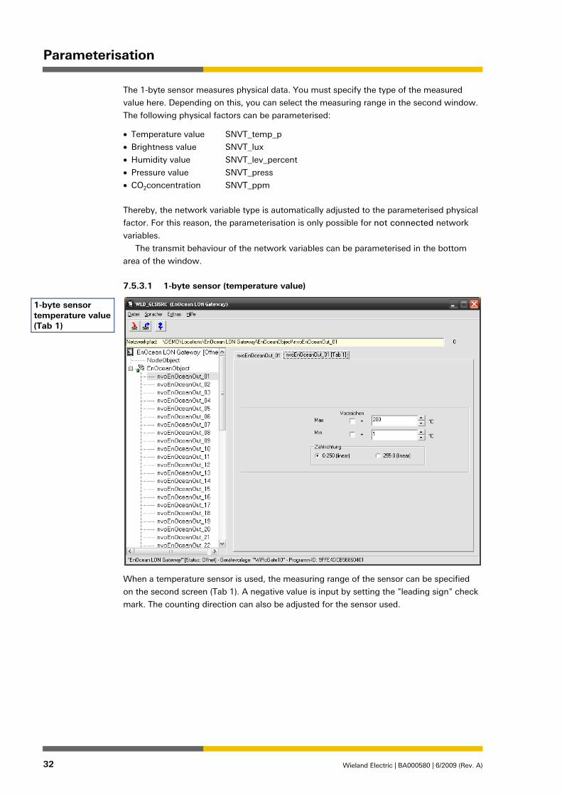
The 1-byte sensor measures physical data. You must specify the type of the measured
value here. Depending on this, you can select the measuring range in the second window.
The following physical factors can be parameterised:
• Temperature value SNVT_temp_p
• Brightness value SNVT_lux
• Humidity value SNVT_lev_percent
• Pressure value SNVT_press
• CO2concentration SNVT_ppm
Thereby, the network variable type is automatically adjusted to the parameterised physical
factor. For this reason, the parameterisation is only possible for not connected network
variables.
The transmit behaviour of the network variables can be parameterised in the bottom
area of the window.
7.5.3.1 1-byte sensor (temperature value)
When a temperature sensor is used, the measuring range of the sensor can be specified
on the second screen (Tab 1). A negative value is input by setting the "leading sign" check
mark. The counting direction can also be adjusted for the sensor used.
1-byte sensor temperature value (Tab 1)

Parameterisation
Wieland Electric | BA000580 | 6/2009 (Rev. A) 33
7.5.3.2 1-byte sensor (brightness value)
When a brightness sensor is used, the measuring range of the sensor can be specified on
the second screen (Tab 1).
7.5.3.3 1-byte sensor (other)
The sensor types CO2 and pressure are present in the selection, however with no func-
tion.
1-byte sensor brightness value (Tab 1)
Notice
Parameterisation
34 Wieland Electric | BA000580 | 6/2009 (Rev. A)
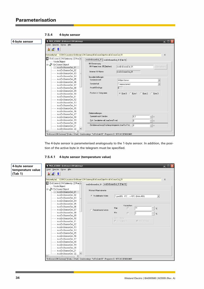
7.5.4 4-byte sensor
The 4-byte sensor is parameterised analogously to the 1-byte sensor. In addition, the posi-
tion of the active byte in the telegram must be specified.
7.5.4.1 4-byte sensor (temperature value)
4-byte sensor
4-byte sensor temperature value (Tab 1)

Parameterisation
Wieland Electric | BA000580 | 6/2009 (Rev. A) 35
When using a temperature sensor, predefined measuring ranges according to the EnOcean
profiles can still be accessed on the second screen (Tab 1) in addition to the parameters
already described.
7.5.4.2 4-byte sensor (brightness value) The 4-byte sensor (brightness value) is parameterised analogously to the 1-byte sensor
(brightness value).
7.5.4.3 4-byte sensor (other)
The sensor types CO2 and pressure are present in the selection, however with no func-
tion.
7.5.5 Alarm transmitter
The Wieland alarm transmitter (83.020.0502.0) is a special module for the control of wire-
less shutter actuators. The alarm transmitter produces a cyclical telegram with the current
status of its potential-free inputs (e.g. conventional wind or rain sensor). As a result, in the
case of a purely wireless-based system, the shutter actuators also move to the security
position in the case of failure of the alarm transmitter.
Only the transit behaviour can be parameterised here.
The alarm transmitter is only used rarely in a LON network; a LON-based weather sta-
tion is usually accessed here. The implementation of the Wieland alarm transmitter in this
gateway is only used for completeness.
Notice
Alarm transmitter

Parameterisation
36 Wieland Electric | BA000580 | 6/2009 (Rev. A)
7.5.6 Window handle
The transmit behaviour of the output variables can be set for the window handle trans-
mission element.
The value of the switch output variables can be parameterised, depending on the applica-
tion (window monitoring, heating or break-in, and/or special solution) on the second
screen (Tab 1).
Window handle
Window handle (Tab 1)

Parameterisation
Wieland Electric | BA000580 | 6/2009 (Rev. A) 37
• Closed only = 0.0 "0; 0" is only transmitted if the window is closed window monitor-
ing heating / break-in
• Open only = 100.1 "100; 1" is only transmitted if the window is open window moni-
toring break-in
• 3 Statuses Special function; "50; 1" is transmitted when the window is tilted

Operation
38 Wieland Electric | BA000580 | 6/2009 (Rev. A)
8 Operation
Before you can teach-in transmitters to buttons and other controls, the configuration of the
device with the LNS Plug-In must be completely finished. Document the assignments to
the channels.
The button numbers stated refer to the illustration on page 14.
8.1 Teach-in of transmitters (Learn; e.g. button)
1. Set the required LON-NV number (0-55) using the channel selector switches (4,5).
2. Check the assigned reaction in the LON network using the Test button (6).
3. Press the Learn button (7) and keep it pressed for longer than three seconds; the green
LED (10) flashes.
4. Let the transmitter to be taught-in transmit three times within two seconds (e.g. press
the button three times in succession).
5. If the radio signal corresponds to the type parameterised with the LNS Plug-In, it will
be taught-in on the channel set by the channel selector switches.
6. The gateway exits the programming mode automatically and the green LED (10) goes
out.
7. Test whether the required function is correct after the teach-in.
You can teach-in other transmitters in the same way.
8.2 Deletion of assignments (Clear)
The LON bus and power supply must be present for the deletion. There are three deletion
variants:
1. Deletion of a single ID from the complete gateway.
2. Deletion of all ID's from a channel.
3. Deletion of all ID's from all channels, restoration of the factory settings.
8.2.1 Variant 1: Delete a single ID
1. Press the Clear button (7) and keep it pressed for longer than three seconds; the red
LED (8) flashes.
2. Transmit an ID three times within two seconds (e.g. press a button three times in
succession) and this ID will be deleted from all channels.
3. The gateway exits the clear mode automatically and the green LED (8) goes out.
4. Check and document the changes.
8.2.2 Variant 2: Delete all IDs from one channel
1. Set the channel to be cleared using the channel selector switches.
2. Press the Clear button (7) and keep it pressed for longer than three seconds; the red
LED (8) flashes.
3. Press the Clear button (7) again and keep it pressed for longer than three seconds. This
deletes all IDs from the channel.
4. The gateway exits the clear mode automatically and the red LED (8) goes out.
5. Check and document the changes.
Operation
Wieland Electric | BA000580 | 6/2009 (Rev. A) 39
8.2.3 Variant 3: Delete all IDs from the gateway (restore factory settings)
1. Set the value "99" using the channel selector switches (4, 5).
2. Press the Clear button (7) and keep it pressed for longer than three seconds; the red
LED (8) flashes.
3. Press the Clear button (7) again and keep it pressed for longer than ten seconds. This
deletes all IDs from the gateway.
4. The gateway exits the clear mode automatically and the red LED (8) goes out.
5. Check and document the changes.

Power supply gesis EIB RM-PS
40 Wieland Electric | BA000580 | 6/2009 (Rev. A)
9 Power supply gesis EIB RM-PS
9.1 Device Description
Designation Power supply
Type, model no. gesis RM-PS 83.020.0401.0
gesis RM-PS B 83.020.0401.1
Device type Power supply
Design Device with screw clamp terminals for installation in a gesis RAN distribution box
Please ensure that you pay strict attention to the warnings and notes in the sections enti-
tled "Proper Use" and "Selecting Personnel and Personnel Qualifications" in Chapter 1.
9.2 Function
The power supply provides the power that is used to operate the basic module. The exten-
sion modules connected to the basic module using the flat cable also receive the current
required for switching the relays from this power supply. The output voltage is a 12 V DC
safety extra-low voltage (SELV).
If you are using the basic module with four extension modules of type RM-0/2W SI
(83.020.0404.0/83.020.0404.1) or RM-0/2W DC (83.020.0407.0/83.020.0407.1) for shutter
control, the power supply RM-PS 12/5 (83.020.0421.0/83.020.0421.1) must be used.
NOTICE
CAUTION
Power supply gesis EIB RM-PS
Wieland Electric | BA000580 | 6/2009 (Rev. A) 41
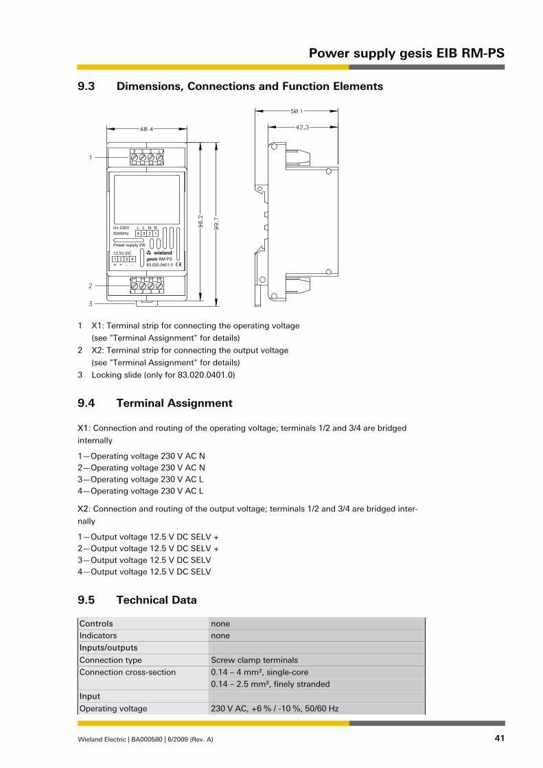
9.3 Dimensions, Connections and Function Elements
+ + -
1
-
L
4
3
W
N
2
4
1
1 2 3 4
4 3 2
2
12.5V DC
Power supply 2W
LUn 230V
3
wieland
N
50/60Hz 1
RM-PS
83.020.0401.0
gesis
1 X1: Terminal strip for connecting the operating voltage
(see "Terminal Assignment" for details)
2 X2: Terminal strip for connecting the output voltage
(see "Terminal Assignment" for details)
3 Locking slide (only for 83.020.0401.0)
9.4 Terminal Assignment
X1: Connection and routing of the operating voltage; terminals 1/2 and 3/4 are bridged
internally
1—Operating voltage 230 V AC N 2—Operating voltage 230 V AC N 3—Operating voltage 230 V AC L 4—Operating voltage 230 V AC L
X2: Connection and routing of the output voltage; terminals 1/2 and 3/4 are bridged inter-
nally
1—Output voltage 12.5 V DC SELV + 2—Output voltage 12.5 V DC SELV + 3—Output voltage 12.5 V DC SELV 4—Output voltage 12.5 V DC SELV
9.5 Technical Data
Controls none Indicators none Inputs/outputs Connection type Screw clamp terminals Connection cross-section 0.14 – 4 mm², single-core 0.14 – 2.5 mm², finely stranded Input Operating voltage 230 V AC, +6 % / -10 %, 50/60 Hz

Power supply gesis EIB RM-PS
42 Wieland Electric | BA000580 | 6/2009 (Rev. A)
Output (connection to basic module)
Rated voltage 12,5 V DC SELV Rated current 160 mA Number of modules that can be connected (max.)
one basic module plus four extension modules; any peak loads occurring with central commands are buff-ered.
Electrical safety Protection class none (depends on subsequent work) Degree of protection IP00, min. IP20 following installation of module in ge-
sis® RAN distribution box Degree of soiling 2 Surge voltage category III Rated insulation voltage 250 V external conductor to N or PE Electrical isolation Air gap/creepage paths > 5.5 mm (supply/output) Environmental conditions Field of application for fixed installation (installation in gesis RAN distribu-
tion boxes) in interior and dry areas Ambient operating temperature -5 to +45 °C Storage temperature -25 to +70 °C Relative humidity 5…93% Moisture condensation none EMC requirements conforms with EN 61000-6-2, EN 61000-6-3 and EN
50090-2-2 Climate resistance according to EN 50090-2-2 Housing material Plastic, halogen and phosphorous-free; colour: black Behaviour in fire (housing) conforms with UL 94 V-2 Weight approx. 240 g Dimensions see "Dimensions, Connections and Function Elements" CE marking in accordance with EMC Directive (residential and func-
tional buildings), Low Voltage Directive
9.6 Installation
9.6.1 Assembly (83.020.0401.0)
1. Latch the module onto the DIN rail.
2. Connect the extension modules to the basic module using the flat cables supplied.
Ensure that, for each pair of extension modules, there is one on the right-hand and one
on the left-hand side of the basic module. Please make a note of which module
addresses are assigned to which slots on the basic module (by providing a label with
"Module no.:"; see diagram under C.). Place the power supply on the outside of the
extension modules, either to the left or right.
3. Establish the connections to both the power supply and EIB using the appropriate
terminal strips.
9.6.2 Disassembly (83.020.0401.0)
1. Disconnect the power supply from the module.
2. Remove the flat cable from the front of the device.
3. Undo the connections at the terminal strips.
4. Insert a screwdriver into the locking slide and release the module from the DIN rail.

Power supply gesis EIB RM-PS
Wieland Electric | BA000580 | 6/2009 (Rev. A) 43
9.6.3 Replacing modules (83.020.0401.1)
1. Disconnect the power supply from the module.
2. Remove the flat cable from the front of the device.
3. Undo the connections at the terminal strips.
4. Slacken the knurled-head screws in the gesis RAN housing (see Fig.
5. Push the slide towards the modules as shown
("1": slide closed; "2": slide open).
Notice: This will release all the modules.
6. Replace the relevant module.
7. Reattach the modules by following steps 1 to 5 in reverse order.

Power supply gesis RM-PS 12/5
44 Wieland Electric | BA000580 | 6/2009 (Rev. A)
10 Power supply gesis RM-PS 12/5
10.1 Device Description
Designation Power supply
Type, model no. gesis RM-PS 12/5 83.020.0421.0
gesis RM-PS 12/5 B 83.020.0421.1
Device type Power supply
Design Device with screw clamp terminals for installation in a gesis RAN distribution box
Please ensure that you pay strict attention to the warnings and notes in the sections enti-
tled "Proper Use" and "Selecting Personnel and Personnel Qualifications" in Chapter 1.
10.2 Function
The power supply is suitable for operating up to two basic modules, including the exten-
sion modules that are connected to them, from the gesis RM series of devices. It has a
wide-range input and is suitable for both DC and AC voltage networks. The output (12.5 V
DC / 5 W) is protected against short circuits, overload and overtemperature.
NOTICE

Power supply gesis RM-PS 12/5
Wieland Electric | BA000580 | 6/2009 (Rev. A) 45
10.3 Dimensions, Connections and Function Elements
+ + -
4
1
-
L
3
3
W
N
2
4
1
1 2 3 4
4 2
gesis
2
12.5V DC
L115-240V
wieland
N3
Power supply 5W
50-400Hz 1
RM-PS 12/583.020.0421.0
1 X1: 4-pin connection terminal strip for connecting the mains voltage
(for details please refer to "Terminal Assignment")
2 X2: 4-pin connection terminal strip for connecting the output voltage
(see "Terminal Assignment" for details)
3 Locking slide (only for 83.020.0421.0)
10.4 Terminal Assignment:
X1: Connection and routing of the mains voltage; terminals 1/2 and 3/4 are bridged inter-
nally
1—Connection for neutral conductor of the mains voltage (N or -) 2—Connection for neutral conductor of the mains voltage (N or −) 3—Connection for phase/external conductor of the mains voltage (L or +) 4—Connection for phase/external conductor of the mains voltage (L or +)
X2: Connection and routing of the output voltage; terminals 1/2 and 3/4 are bridged inter-
nally
1—Connection for output voltage, 12.5 V DC + 2—Connection for output voltage, 12.5 V DC + 3—Connection for output voltage, 12.5 V DC – 4—Connection for output voltage, 12.5 V DC –

Power supply gesis RM-PS 12/5
46 Wieland Electric | BA000580 | 6/2009 (Rev. A)
10.5 Technical Data
Mains power input (connection X1)
85…264 V AC (for 85 V AC 80 % power, from 115 V AC 100%) 120…370 V DC
Frequency range 47…440 Hz Efficiency typically 73 % AC current consumption typically 0.12 A/115 V AC
typically 0.08 A/230 V AC Output (connection X2) Rated voltage 12,5 V DC ± 4 % (SELV)
(I/O isolation according to EN 60601-1) Rated current 400 mA Power 5 W Short circuit withstand capability Yes Overload protection Yes Overtemperature protection Yes Connection type (X1 and X2) Screw clamp terminals
0.14 to 4 mm², single-core 0.14 to 2.5 mm², finely stranded 6.5 mm stripped in each case
Electrical safety Protection class none Degree of protection IP 20 Degree of soiling 2 Surge voltage category III Rated insulation voltage 250 V external conductor to N or PE Electrical isolation Air gap/creepage paths > 5.5 mm (supply/output) Environmental conditions Ambient operating temperature −5°C to +45°C Storage temperature −25°C to +70°C relative humidity 5% - 93% Moisture condensation not permitted General data Housing material Plastic, halogen-free Housing colour black Behaviour in fire V2 according to UL (housing) Weight approx. 110 g Dimensions see "Dimensions, Connections and Function Elements"Height including TH 35-7.5 mounting rail
52 mm
CE marking according to EMC Directive (residential and functional buildings), Low Voltage Directive
Mounting on TH 35 mounting rail

Power supply gesis RM-PS 12/5
Wieland Electric | BA000580 | 6/2009 (Rev. A) 47
10.6 Installation
10.6.1 Assembly (83.020.0421.0)
1. Latch the module onto the DIN rail.
2. Connect the extension modules to the basic module using the flat cables supplied.
Ensure that, for each pair of extension modules, there is one on the right-hand and one
on the left-hand side of the basic module. Please make a note of which module
addresses are assigned to which slots on the
basic module (by providing a label with "Module no.:"; see diagram under C.). Place
the power supply on the outside of the extension modules, either to the left or right.
3. Establish the connections to both the power supply and EIB using the appropriate
terminal strips.
10.6.2 Disassembly (83.020.0421.0)
1. Disconnect the power supply from the module.
2. Remove the flat cable from the front of the device.
3. Undo the connections at the terminal strips.
4. Insert a screwdriver into the locking slide and release the module from the DIN rail.
10.6.3 Replacing modules (83.020.0421.1)
1. Disconnect the power supply from the module.
2. Remove the flat cable from the front of the device.
3. Undo the connections at the terminal strips.
4. Slacken the knurled-head screws in the gesis RAN housing (see Fig.
5. Push the slide towards the modules as shown
("1": slide closed; "2": slide open).
Notice: This will release all the modules.
6. Replace the relevant module.
7. Reattach the modules by following steps 1 to 5 in reverse order.