Embed Size (px)
Citation preview
Gesture Sensor LabFor the MAX® 10 DECA FPGA Evaluation Kit
TABLE OF CONTENTSLAB 4. GESTURE SENSOR LAB ..................................................................................................................... 144
4.1 Getting Started ........................................................................................................................................ 1444.2 Examine the System Design ................................................................................................................... 145
4.2.1 Examine the System Tool Flow ...................................................................................................... 1454.2.2 Examine the DECA Development Platform .................................................................................... 146
4.3 Set Up the Quartus II Project .................................................................................................................. 1474.3.1 Extract the lab files.......................................................................................................................... 1484.3.2 Create a new Quartus II Project...................................................................................................... 148
4.4 Build the Hardware Design ..................................................................................................................... 1504.4.1 Launch Qsys ................................................................................................................................... 1504.4.2 Configure the Clock ........................................................................................................................ 1514.4.3 Add a Nios II Processor .................................................................................................................. 1524.4.4 Add On-Chip Memory ..................................................................................................................... 1544.4.5 Add the JTAG UART Peripheral ..................................................................................................... 1554.4.6 Add a PLL ....................................................................................................................................... 1574.4.7 Add a Timer..................................................................................................................................... 1614.4.8 Add a System ID Peripheral............................................................................................................ 1624.4.9 Add an Interrupt Pin ........................................................................................................................ 1634.4.10 Add an I2C Peripheral..................................................................................................................... 1654.4.11 Connect the Qsys system and remove errors ................................................................................ 1674.4.12 Set Interrupt Priorities ..................................................................................................................... 1704.4.13 Define the Nios II Reset and Exception Vectors............................................................................. 1714.4.14 Resolve Memory Addresses ........................................................................................................... 1724.4.15 Check the full system...................................................................................................................... 1734.4.16 Generate the Qsys System............................................................................................................. 1754.4.17 Add the Qsys System to the Quartus Project ................................................................................. 1764.4.18 Modify the Top-Level Design File ................................................................................................... 1774.4.19 Import Pin Assignments .................................................................................................................. 1794.4.20 Compile the Quartus II project ........................................................................................................ 1794.4.21 Download the Configuration File to DECA...................................................................................... 182
4.5 Create the Software Design ................................................................................................................. 1854.5.1 Start Nios II Software Build Tools for Eclipse ................................................................................. 1864.5.2 Create a New Software Project....................................................................................................... 1874.5.3 Add Source Code to the Project ..................................................................................................... 1894.5.4 Configure the Board Support Package ........................................................................................... 1904.5.5 Configure the Application Project.................................................................................................... 1944.5.6 Build the Software Project............................................................................................................... 195
4.6 Run the Application on the DECA board................................................................................................. 1974.6.1 Download the Executable to the DECA .......................................................................................... 197
Version 15.0 6/07/2015
LAB 4. Gesture Sensor Lab
144 Max10 DECA Workshop Manual
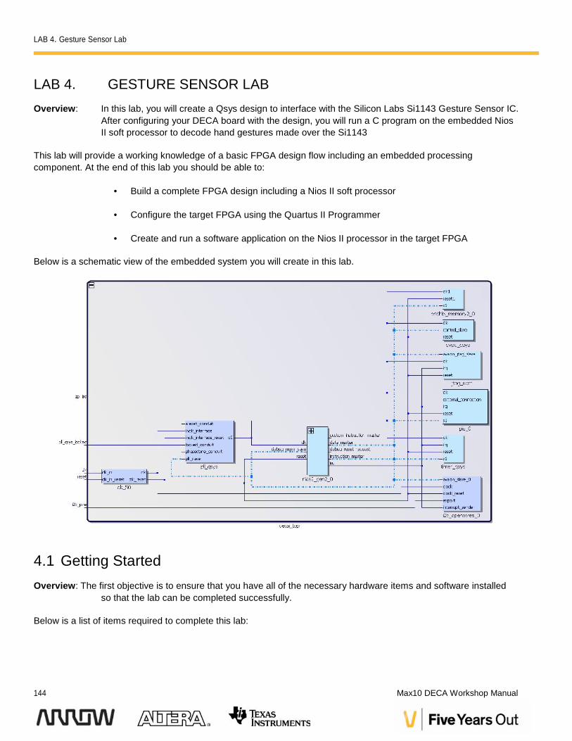
LAB 4. GESTURE SENSOR LABOverview: In this lab, you will create a Qsys design to interface with the Silicon Labs Si1143 Gesture Sensor IC.
After configuring your DECA board with the design, you will run a C program on the embedded NiosII soft processor to decode hand gestures made over the Si1143
This lab will provide a working knowledge of a basic FPGA design flow including an embedded processingcomponent. At the end of this lab you should be able to:
Build a complete FPGA design including a Nios II soft processor
Configure the target FPGA using the Quartus II Programmer
Create and run a software application on the Nios II processor in the target FPGA
Below is a schematic view of the embedded system you will create in this lab.
4.1 Getting StartedOverview: The first objective is to ensure that you have all of the necessary hardware items and software installed
so that the lab can be completed successfully.
Below is a list of items required to complete this lab:
LAB 4. Gesture Sensor Lab
Version 15.0 145
Arrow DECA Evaluation Kit
USB cable
Lab files
Quartus II 15.0 Design Software
Personal computer or laptop running Windows 7 with at least an Intel i3 core (or equivalent),4 GB of RAM, and 12 GB of free hard disk space
A desire to learn
If you are missing one of these items, please let your instructor know. Instructions for how to download Quartus canbe found in the Appendix.
4.2 Examine the System DesignOverview: In this section, you will examine the design flow used in modern Altera FGPA designs.
4.2.1 Examine the System Tool FlowDeveloping software for an Altera system on a programmable chip requires an understanding of the design flowbetween the Qsys system integration tool and the Nios II Embedded Development Suite (EDS). Typically, designrequirements begin with requirements and become inputs to system definitions. System definition is the first step inthe design flow process. For this workshop, the design will be built and then the FPGA image will be downloadedinto the dev board. The objective of the module is to review the development tools that will be used.
LAB 4. Gesture Sensor Lab
146 Max10 DECA Workshop Manual
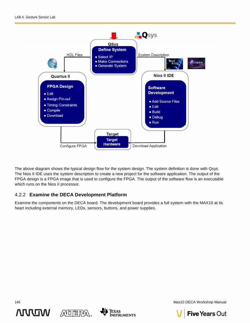
The above diagram shows the typical design flow for the system design. The system definition is done with Qsys.The Nios II IDE uses the system description to create a new project for the software application. The output of theFPGA design is a FPGA image that is used to configure the FPGA. The output of the software flow is an executablewhich runs on the Nios II processor.
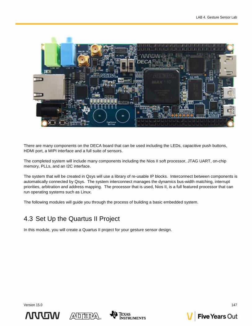
4.2.2 Examine the DECA Development PlatformExamine the components on the DECA board. The development board provides a full system with the MAX10 at itsheart including external memory, LEDs, sensors, buttons, and power supplies.
LAB 4. Gesture Sensor Lab
Version 15.0 147
There are many components on the DECA board that can be used including the LEDs, capacitive push buttons,HDMI port, a MIPI interface and a full suite of sensors.
The completed system will include many components including the Nios II soft processor, JTAG UART, on-chipmemory, PLLs, and an I2C interface.
The system that will be created in Qsys will use a library of re-usable IP blocks. Interconnect between components isautomatically connected by Qsys. The system interconnect manages the dynamics bus-width matching, interruptpriorities, arbitration and address mapping. The processor that is used, Nios II, is a full featured processor that canrun operating systems such as Linux.
The following modules will guide you through the process of building a basic embedded system.
4.3 Set Up the Quartus II ProjectIn this module, you will create a Quartus II project for your gesture sensor design.
LAB 4. Gesture Sensor Lab
148 Max10 DECA Workshop Manual
4.3.1 Extract the lab files
4.3.1.1 Create a new directory on your computer and ensure that there are no spaces in the directory path. Thiswill cause problems with the software tools. Call this new directory gesture_lab.
4.3.1.2 Extract the workshop files into this new directory.
4.3.2 Create a new Quartus II Project
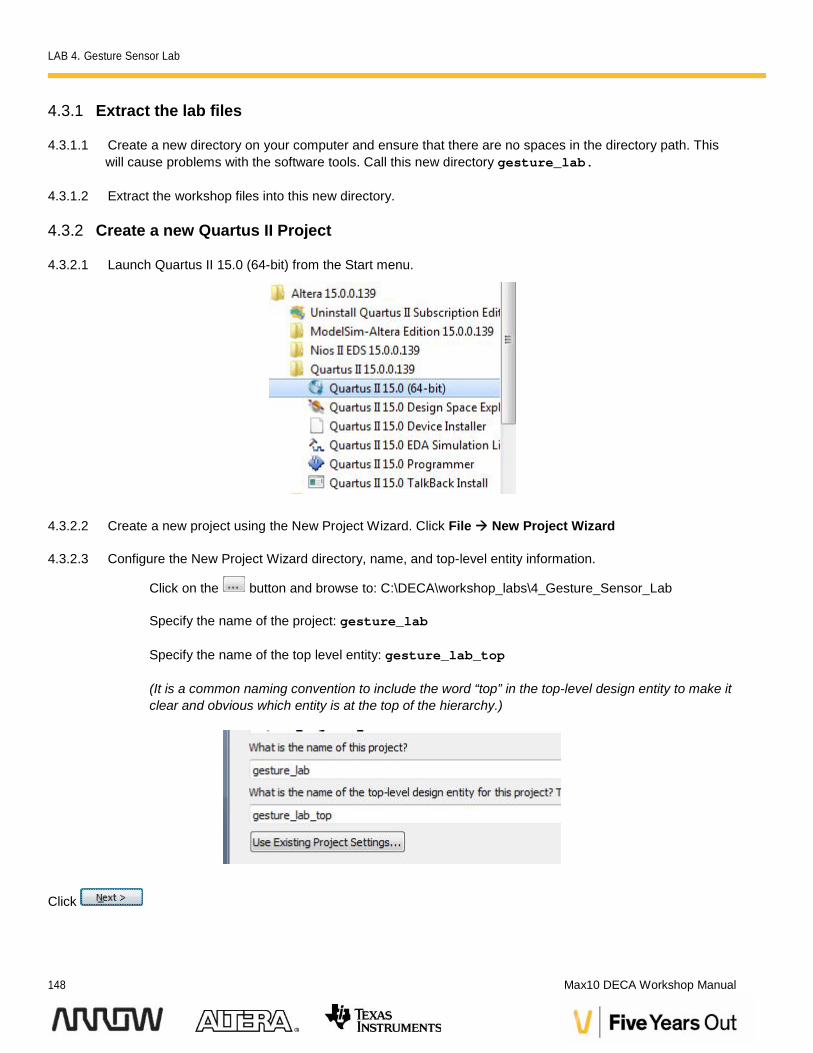
4.3.2.1 Launch Quartus II 15.0 (64-bit) from the Start menu.
4.3.2.2 Create a new project using the New Project Wizard. Click File New Project Wizard
4.3.2.3 Configure the New Project Wizard directory, name, and top-level entity information.
Click on the button and browse to: C:\DECA\workshop_labs\4_Gesture_Sensor_Lab
Specify the name of the project: gesture_lab
Specify the name of the top level entity: gesture_lab_top
(It is a common naming convention to include the word “top” in the top-level design entity to make itclear and obvious which entity is at the top of the hierarchy.)
Click
LAB 4. Gesture Sensor Lab
Version 15.0 149
4.3.2.4 On the Project Type page, select "Empty Project" and click
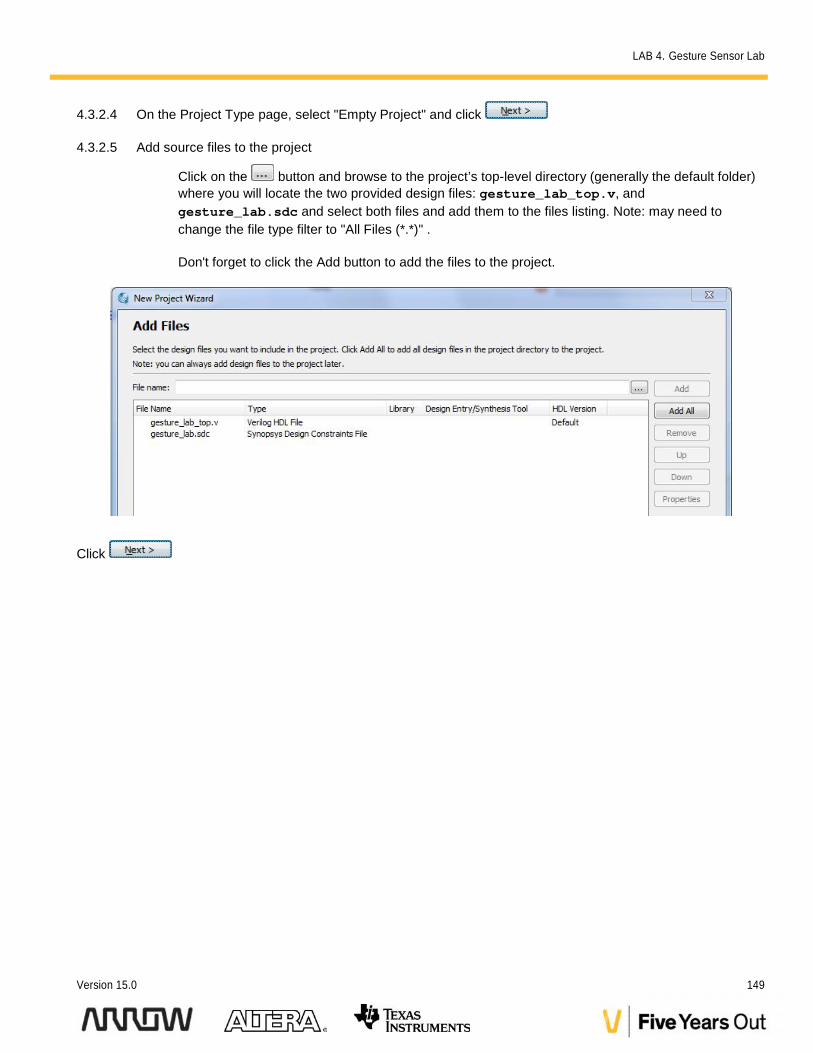
4.3.2.5 Add source files to the project
Click on the button and browse to the project’s top-level directory (generally the default folder)where you will locate the two provided design files: gesture_lab_top.v, andgesture_lab.sdc and select both files and add them to the files listing. Note: may need tochange the file type filter to "All Files (*.*)" .
Don't forget to click the Add button to add the files to the project.
Click
LAB 4. Gesture Sensor Lab
150 Max10 DECA Workshop Manual
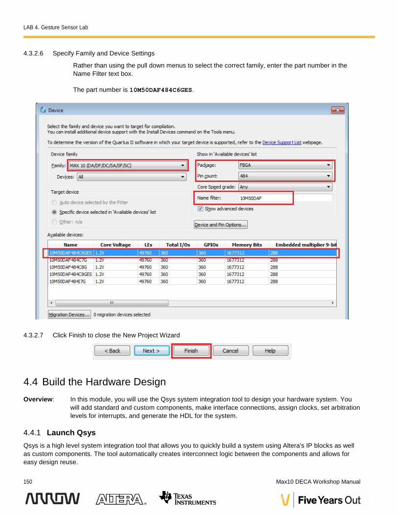
4.3.2.6 Specify Family and Device Settings
Rather than using the pull down menus to select the correct family, enter the part number in theName Filter text box.
The part number is 10M50DAF484C6GES.
4.3.2.7 Click Finish to close the New Project Wizard
4.4 Build the Hardware DesignOverview: In this module, you will use the Qsys system integration tool to design your hardware system. You
will add standard and custom components, make interface connections, assign clocks, set arbitrationlevels for interrupts, and generate the HDL for the system.
4.4.1 Launch QsysQsys is a high level system integration tool that allows you to quickly build a system using Altera's IP blocks as wellas custom components. The tool automatically creates interconnect logic between the components and allows foreasy design reuse.
LAB 4. Gesture Sensor Lab
Version 15.0 151
A Qsys system is made up of a number of components and the automatically generated, high performanceinterconnect between them. Qsys allows you to connect components on an interface level, rather than a signal bysignal level. Qsys understands the different types of interfaces and will only allow connections between interfaces ofthe same type (i.e. a data master connects to a data slave, clock source to clock sink, etc…).
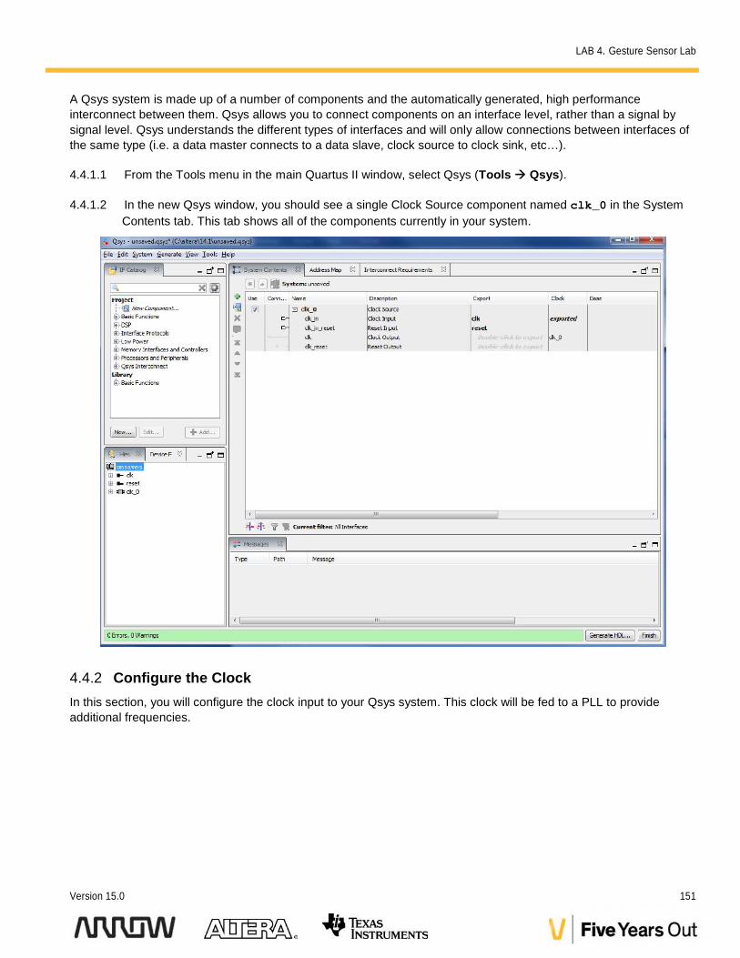
4.4.1.1 From the Tools menu in the main Quartus II window, select Qsys (Tools Qsys).
4.4.1.2 In the new Qsys window, you should see a single Clock Source component named clk_0 in the SystemContents tab. This tab shows all of the components currently in your system.
4.4.2 Configure the ClockIn this section, you will configure the clock input to your Qsys system. This clock will be fed to a PLL to provideadditional frequencies.
LAB 4. Gesture Sensor Lab
152 Max10 DECA Workshop Manual
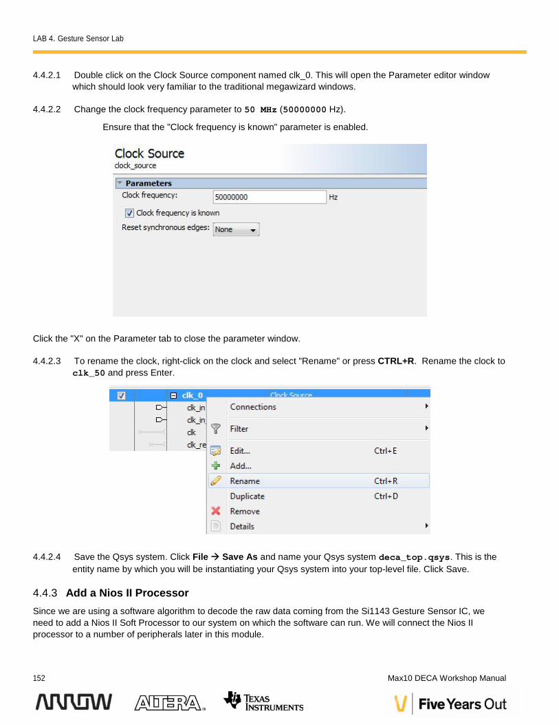
4.4.2.1 Double click on the Clock Source component named clk_0. This will open the Parameter editor windowwhich should look very familiar to the traditional megawizard windows.
4.4.2.2 Change the clock frequency parameter to 50 MHz (50000000 Hz).
Ensure that the "Clock frequency is known" parameter is enabled.
Click the "X" on the Parameter tab to close the parameter window.
4.4.2.3 To rename the clock, right-click on the clock and select "Rename" or press CTRL+R. Rename the clock toclk_50 and press Enter.
4.4.2.4 Save the Qsys system. Click File Save As and name your Qsys system deca_top.qsys. This is theentity name by which you will be instantiating your Qsys system into your top-level file. Click Save.
4.4.3 Add a Nios II ProcessorSince we are using a software algorithm to decode the raw data coming from the Si1143 Gesture Sensor IC, weneed to add a Nios II Soft Processor to our system on which the software can run. We will connect the Nios IIprocessor to a number of peripherals later in this module.
LAB 4. Gesture Sensor Lab
Version 15.0 153
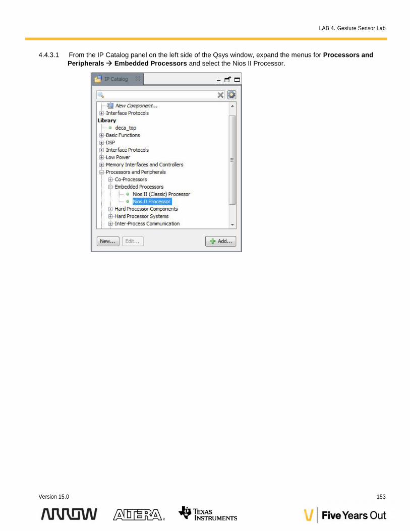
4.4.3.1 From the IP Catalog panel on the left side of the Qsys window, expand the menus for Processors andPeripherals Embedded Processors and select the Nios II Processor.
LAB 4. Gesture Sensor Lab
154 Max10 DECA Workshop Manual
Note that MAX10 devices do not support the Nios II (Classic) Processor. However, all codedeveloped on the classic version is fully forward compatible.
4.4.3.2 Double click on the name or click "Add…" to add the component to the system. The Nios II parametereditor window will open.
4.4.3.3 In the Main tab, ensure that the "Nios II/e" option is selected.
4.4.3.4 The settings in the Vectors tab will be set in a later step so skip that for now.
Note that until these settings are applied, the following two errors in the Qsys window are expected.
Error: nios2_gen2_0: Reset slave is not specified. Please select the reset slave.
Error: nios2_gen2_0: Exception slave is not specified. Please select the exception slave
4.4.3.5 The settings in the other tabs are left as their defaults but feel free to explore the parameter editor and seewhat settings can be applied to the Nios II. Click Finish.
Note that there will be errors related to clocks as well. This will be resolved in a few steps.
4.4.3.6 Rename the Nios II to nios2_qsys.
4.4.4 Add On-Chip MemoryAltera FPGAs provide internal on-chip memory blocks that that can be used to build up an internal RAM (or ROM)block of memory. In this lab, this provides the Nios II with access to very low-latency high speed memory forexecutable code and variable storage.
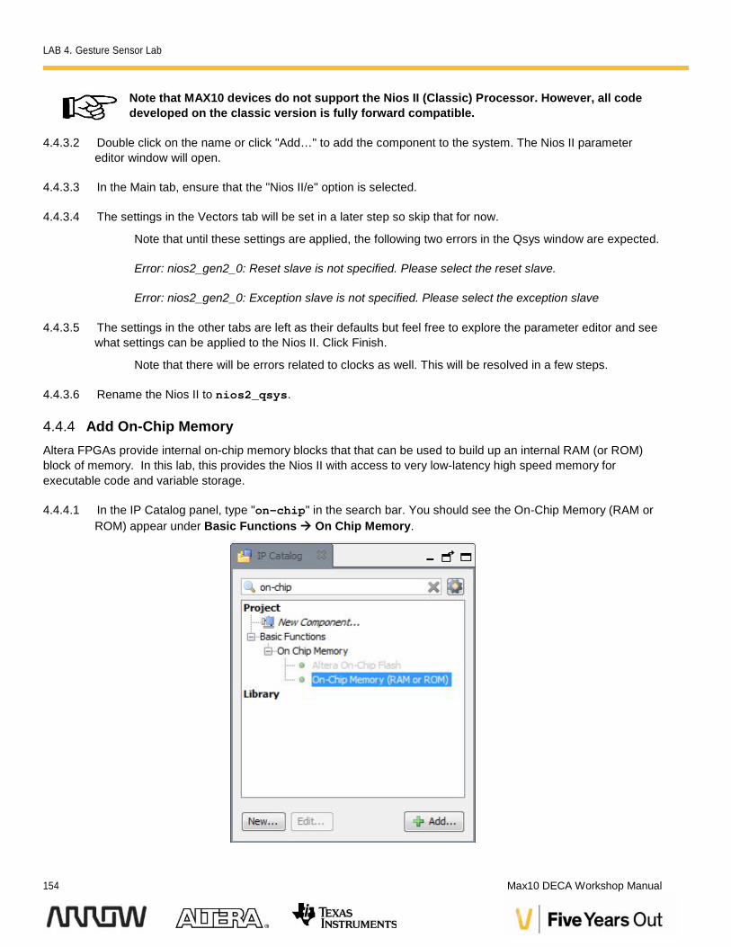
4.4.4.1 In the IP Catalog panel, type "on-chip" in the search bar. You should see the On-Chip Memory (RAM orROM) appear under Basic Functions On Chip Memory.
LAB 4. Gesture Sensor Lab
Version 15.0 155
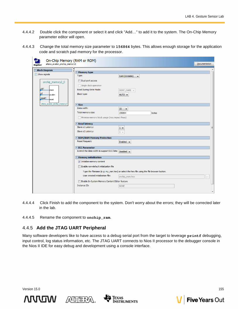
4.4.4.2 Double click the component or select it and click "Add…" to add it to the system. The On-Chip Memoryparameter editor will open.
4.4.4.3 Change the total memory size parameter to 156864 bytes. This allows enough storage for the applicationcode and scratch pad memory for the processor.
4.4.4.4 Click Finish to add the component to the system. Don't worry about the errors; they will be corrected laterin the lab.
4.4.4.5 Rename the component to onchip_ram.
4.4.5 Add the JTAG UART PeripheralMany software developers like to have access to a debug serial port from the target to leverage printf debugging,input control, log status information, etc. The JTAG UART connects to Nios II processor to the debugger console inthe Nios II IDE for easy debug and development using a console interface.
LAB 4. Gesture Sensor Lab
156 Max10 DECA Workshop Manual
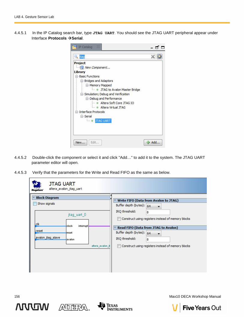
4.4.5.1 In the IP Catalog search bar, type JTAG UART. You should see the JTAG UART peripheral appear underInterface ProtocolsSerial.
4.4.5.2 Double-click the component or select it and click "Add…" to add it to the system. The JTAG UARTparameter editor will open.
4.4.5.3 Verify that the parameters for the Write and Read FIFO as the same as below.
LAB 4. Gesture Sensor Lab
Version 15.0 157
4.4.5.4 Click Finish to add the component to the system. Don’t worry about the errors; they will be addressed later.
4.4.5.5 Rename the component jtag_uart.
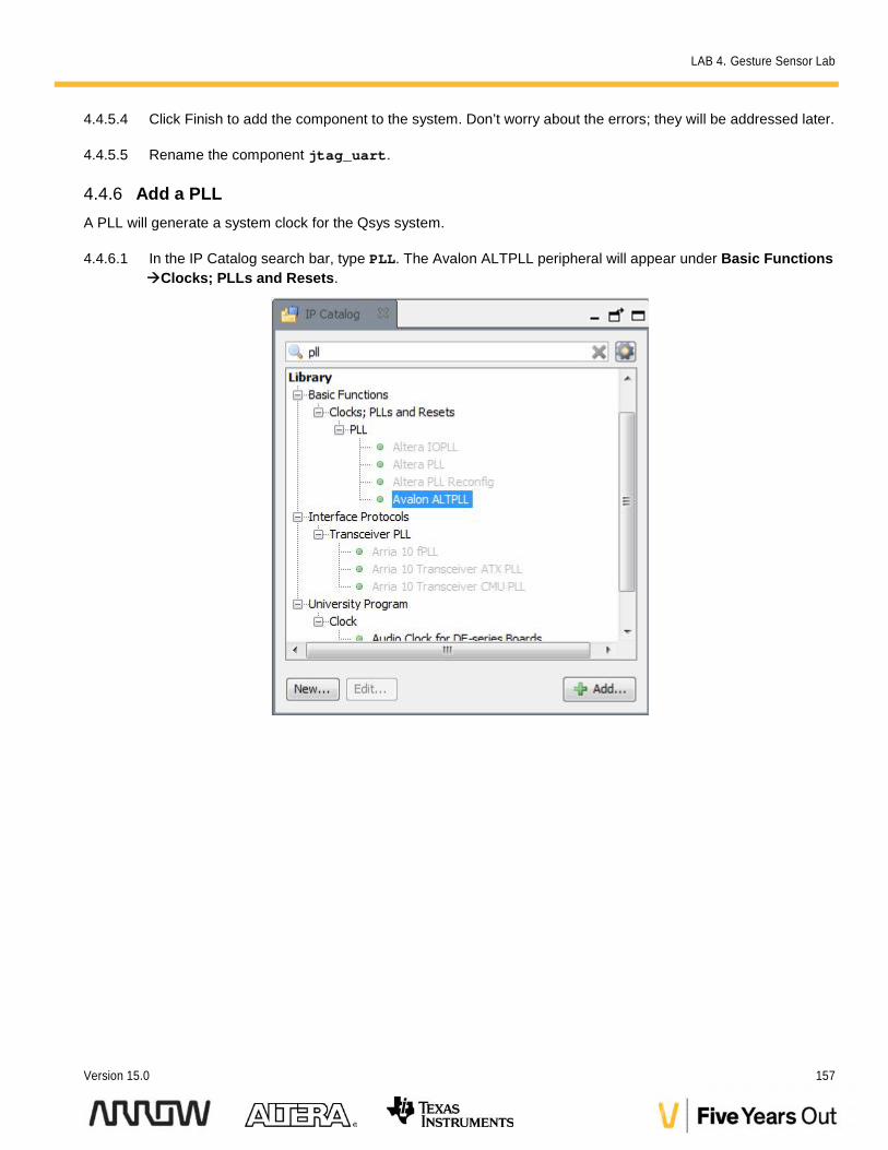
4.4.6 Add a PLLA PLL will generate a system clock for the Qsys system.
4.4.6.1 In the IP Catalog search bar, type PLL. The Avalon ALTPLL peripheral will appear under Basic FunctionsClocks; PLLs and Resets.
LAB 4. Gesture Sensor Lab
158 Max10 DECA Workshop Manual
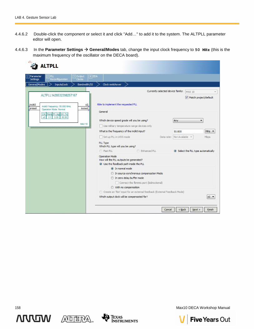
4.4.6.2 Double-click the component or select it and click "Add…" to add it to the system. The ALTPLL parametereditor will open.
4.4.6.3 In the Parameter Settings General/Modes tab, change the input clock frequency to 50 MHz (this is themaximum frequency of the oscillator on the DECA board).
LAB 4. Gesture Sensor Lab
Version 15.0 159
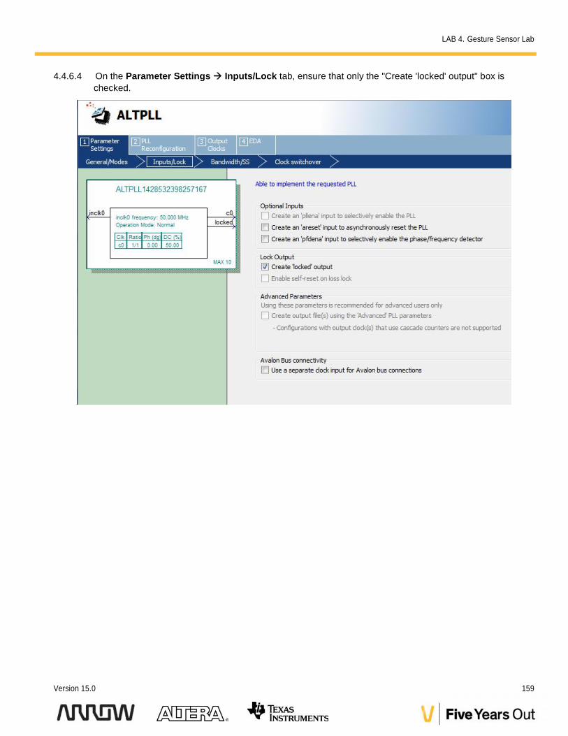
4.4.6.4 On the Parameter Settings Inputs/Lock tab, ensure that only the "Create 'locked' output" box ischecked.
LAB 4. Gesture Sensor Lab
160 Max10 DECA Workshop Manual
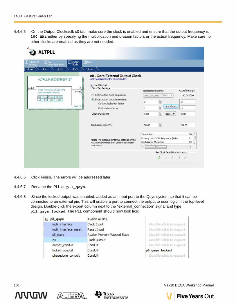
4.4.6.5 On the Output Clocks/clk c0 tab, make sure the clock is enabled and ensure that the output frequency is100 MHz either by specifying the multiplication and division factors or the actual frequency. Make sure noother clocks are enabled as they are not needed.
4.4.6.6 Click Finish. The errors will be addressed later.
4.4.6.7 Rename the PLL as pll_qsys.
4.4.6.8 Since the locked output was enabled, added as an input port to the Qsys system so that it can beconnected to an external pin. This will enable a port to connect the output to user logic in the top-leveldesign. Double-click the export column next to the "external_connection" signal and typepll_qsys_locked. The PLL component should now look like:
LAB 4. Gesture Sensor Lab
Version 15.0 161
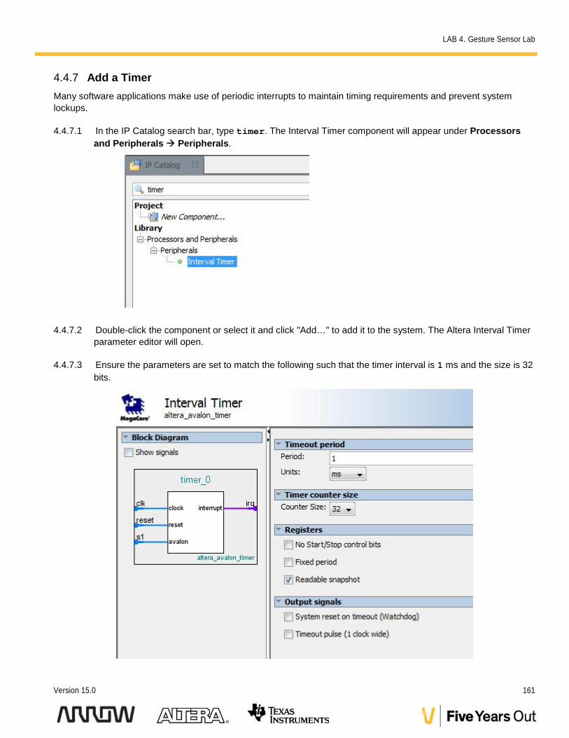
4.4.7 Add a TimerMany software applications make use of periodic interrupts to maintain timing requirements and prevent systemlockups.
4.4.7.1 In the IP Catalog search bar, type timer. The Interval Timer component will appear under Processorsand Peripherals Peripherals.
4.4.7.2 Double-click the component or select it and click "Add…" to add it to the system. The Altera Interval Timerparameter editor will open.
4.4.7.3 Ensure the parameters are set to match the following such that the timer interval is 1 ms and the size is 32bits.
LAB 4. Gesture Sensor Lab
162 Max10 DECA Workshop Manual
4.4.7.4 Click Finish. Do not worry about the warnings/errors as they will be fixed once we connect the clock to theIP.
4.4.7.5 Rename the component timer_qsys.
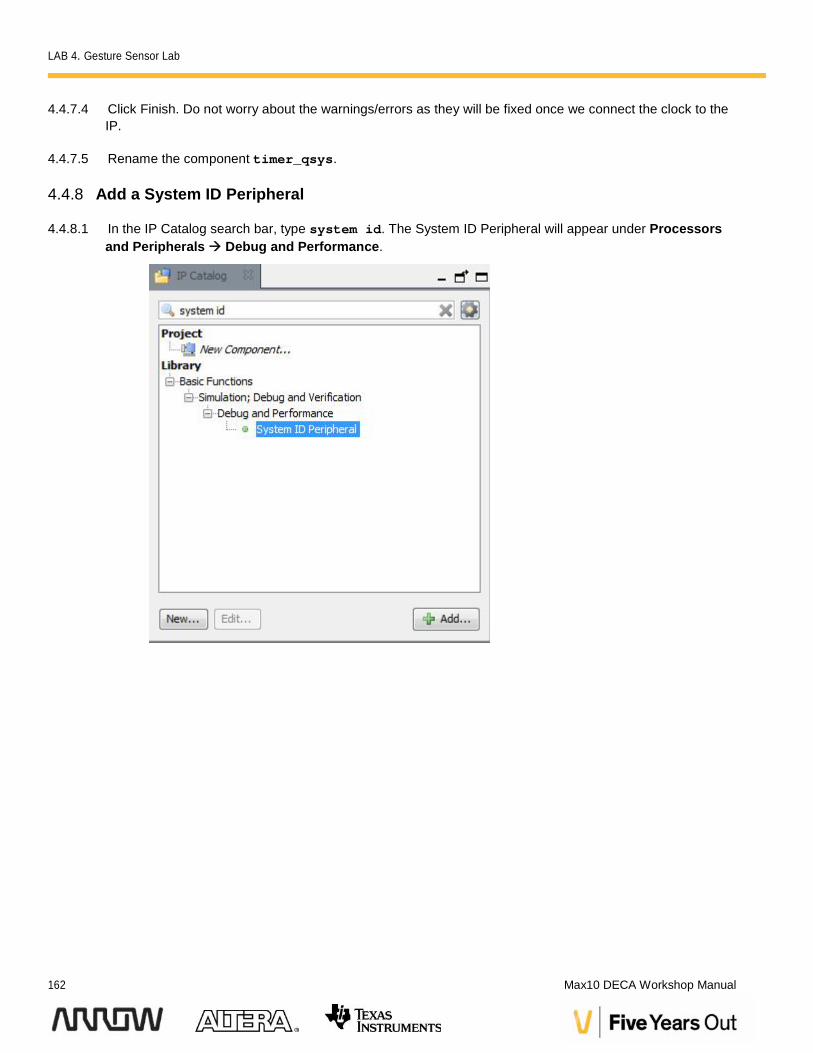
4.4.8 Add a System ID Peripheral
4.4.8.1 In the IP Catalog search bar, type system id. The System ID Peripheral will appear under Processorsand Peripherals Debug and Performance.
LAB 4. Gesture Sensor Lab
Version 15.0 163
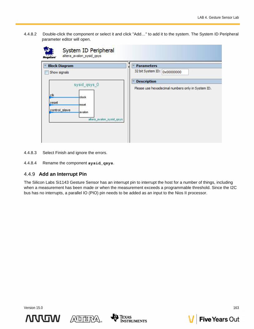
4.4.8.2 Double-click the component or select it and click "Add…" to add it to the system. The System ID Peripheralparameter editor will open.
4.4.8.3 Select Finish and ignore the errors.
4.4.8.4 Rename the component sysid_qsys.
4.4.9 Add an Interrupt PinThe Silicon Labs Si1143 Gesture Sensor has an interrupt pin to interrupt the host for a number of things, includingwhen a measurement has been made or when the measurement exceeds a programmable threshold. Since the I2Cbus has no interrupts, a parallel IO (PIO) pin needs to be added as an input to the Nios II processor.
LAB 4. Gesture Sensor Lab
164 Max10 DECA Workshop Manual
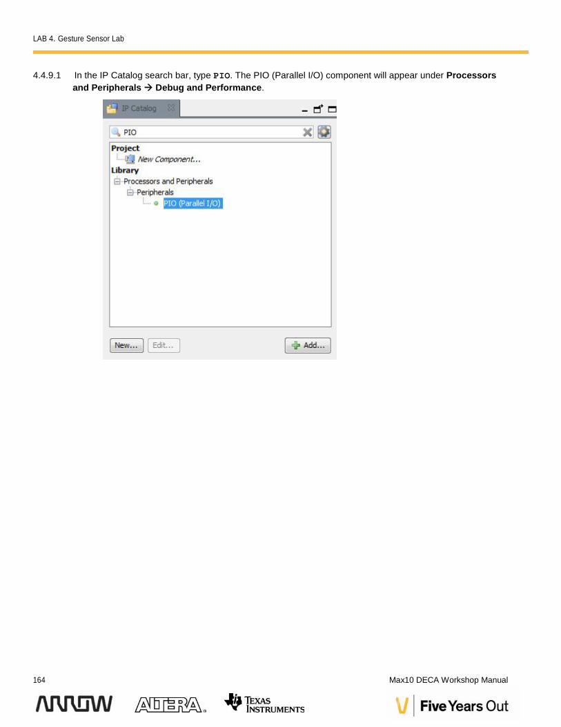
4.4.9.1 In the IP Catalog search bar, type PIO. The PIO (Parallel I/O) component will appear under Processorsand Peripherals Debug and Performance.
LAB 4. Gesture Sensor Lab
Version 15.0 165
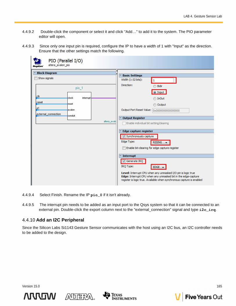
4.4.9.2 Double-click the component or select it and click "Add…" to add it to the system. The PIO parametereditor will open.
4.4.9.3 Since only one input pin is required, configure the IP to have a width of 1 with "Input" as the direction.Ensure that the other settings match the following.
4.4.9.4 Select Finish. Rename the IP pio_0 if it isn't already.
4.4.9.5 The interrupt pin needs to be added as an input port to the Qsys system so that it can be connected to anexternal pin. Double-click the export column next to the "external_connection" signal and type i2c_irq.
4.4.10 Add an I2C PeripheralSince the Silicon Labs Si1143 Gesture Sensor communicates with the host using an I2C bus, an I2C controller needsto be added to the design.
LAB 4. Gesture Sensor Lab
166 Max10 DECA Workshop Manual
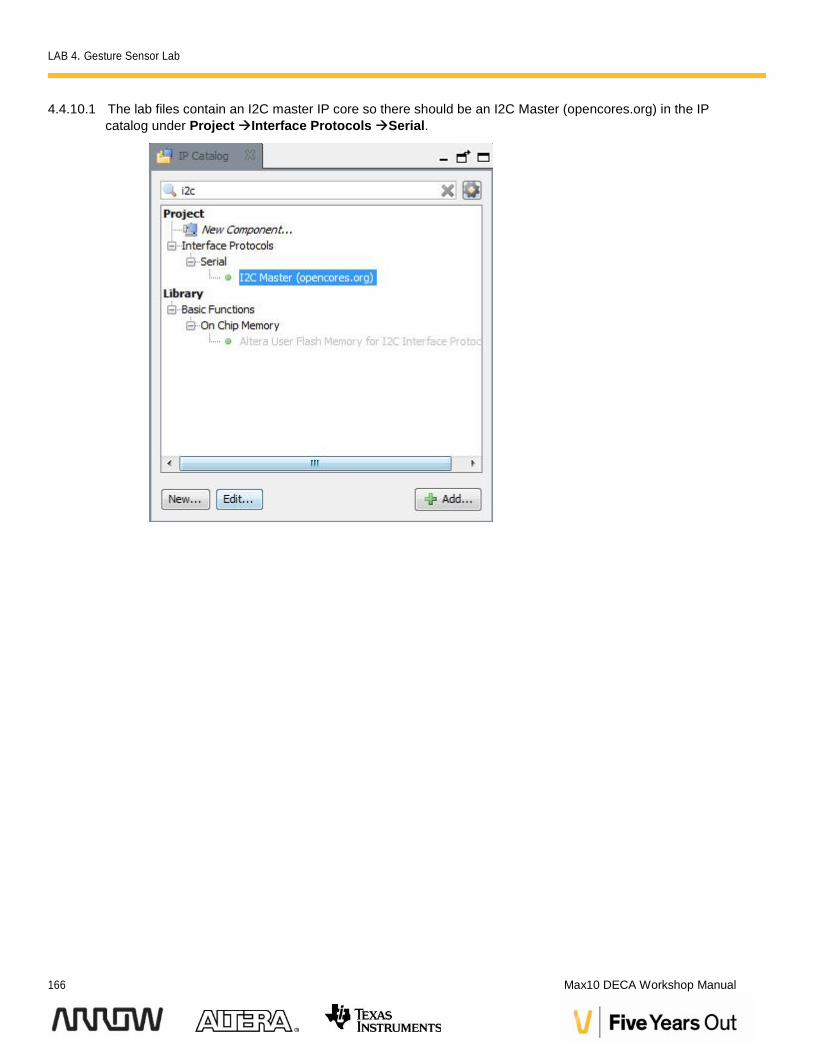
4.4.10.1 The lab files contain an I2C master IP core so there should be an I2C Master (opencores.org) in the IPcatalog under ProjectInterface ProtocolsSerial.
LAB 4. Gesture Sensor Lab
Version 15.0 167
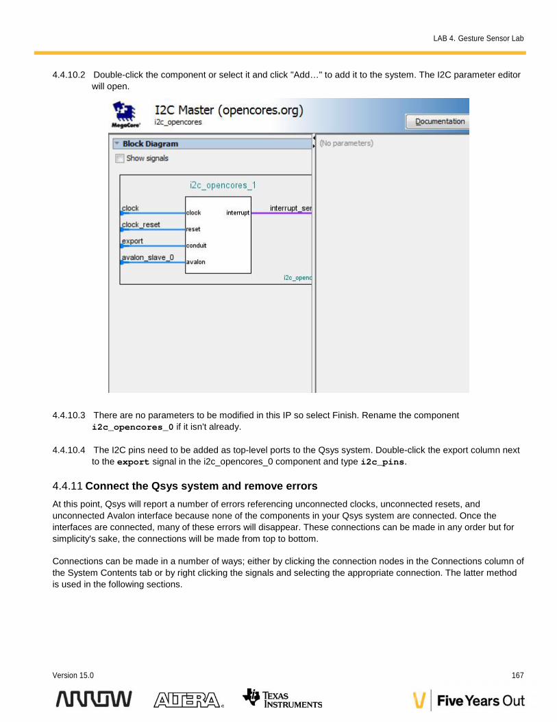
4.4.10.2 Double-click the component or select it and click "Add…" to add it to the system. The I2C parameter editorwill open.
4.4.10.3 There are no parameters to be modified in this IP so select Finish. Rename the componenti2c_opencores_0 if it isn't already.
4.4.10.4 The I2C pins need to be added as top-level ports to the Qsys system. Double-click the export column nextto the export signal in the i2c_opencores_0 component and type i2c_pins.
4.4.11 Connect the Qsys system and remove errorsAt this point, Qsys will report a number of errors referencing unconnected clocks, unconnected resets, andunconnected Avalon interface because none of the components in your Qsys system are connected. Once theinterfaces are connected, many of these errors will disappear. These connections can be made in any order but forsimplicity's sake, the connections will be made from top to bottom.
Connections can be made in a number of ways; either by clicking the connection nodes in the Connections column ofthe System Contents tab or by right clicking the signals and selecting the appropriate connection. The latter methodis used in the following sections.
LAB 4. Gesture Sensor Lab
168 Max10 DECA Workshop Manual
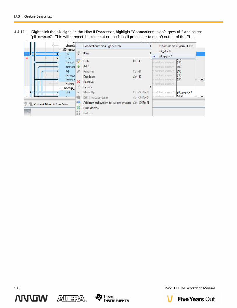
4.4.11.1 Right click the clk signal in the Nios II Processor, highlight "Connections: nios2_qsys.clk" and select"pll_qsys.c0". This will connect the clk input on the Nios II processor to the c0 output of the PLL.

LAB 4. Gesture Sensor Lab
Version 15.0 169
Signal names are referred to by the following convention: <component_name.signal_name>where "component_name" refers to the name of the Qsys component in the Name column ofthe System Contents tab and "signal_name" refers to the signal or interface within thecomponent.
The small arrows in the connections column denote whether the interface or signal is asource or a sink.
4.4.11.2 Repeat the same steps of connecting signals following the table below. Interfaces might be connected tomore than one component and the order of the connections does not matter. For simplicity, the table liststhe connections starting with the source component at the top of the Qsys system.
Source Signal Sink Signal
clk_50.clk i2c_opencores_0.clock
pll_qsys.inclk_interface
clk_50.clk_reset i2c_opencores_0.clock_reset
jtag_uart.reset
nios2_qsys.reset
onchip_ram.reset
pio_0.reset
pll_qsys.inclk_interface_reset
sysid_qsys.reset
timer_qsys.reset
nios2_qsys.data_master i2c_opencores_0.avalon_slave_0
jtag_uart.avalong_jtag_slave
nios2_qsys.debug_mem_slave
onchip_ram.s1
pio_0.s1
pll_qsys.pll_slave
sysid_qsys.control_slave
timer_qsys.s1
nios2_qsys.instruction_master nios2_qsys.debug_mem_slave
onchip_ram.s1
timer_qsys.irq nios2_qsys.irq
LAB 4. Gesture Sensor Lab
170 Max10 DECA Workshop Manual
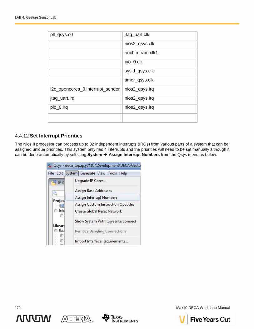
pll_qsys.c0 jtag_uart.clk
nios2_qsys.clk
onchip_ram.clk1
pio_0.clk
sysid_qsys.clk
timer_qsys.clk
i2c_opencores_0.interrupt_sender nios2_qsys.irq
jtag_uart.irq nios2_qsys.irq
pio_0.irq nios2_qsys.irq
4.4.12 Set Interrupt PrioritiesThe Nios II processor can process up to 32 independent interrupts (IRQs) from various parts of a system that can beassigned unique priorities. This system only has 4 interrupts and the priorities will need to be set manually although itcan be done automatically by selecting System Assign Interrupt Numbers from the Qsys menu as below.
LAB 4. Gesture Sensor Lab
Version 15.0 171
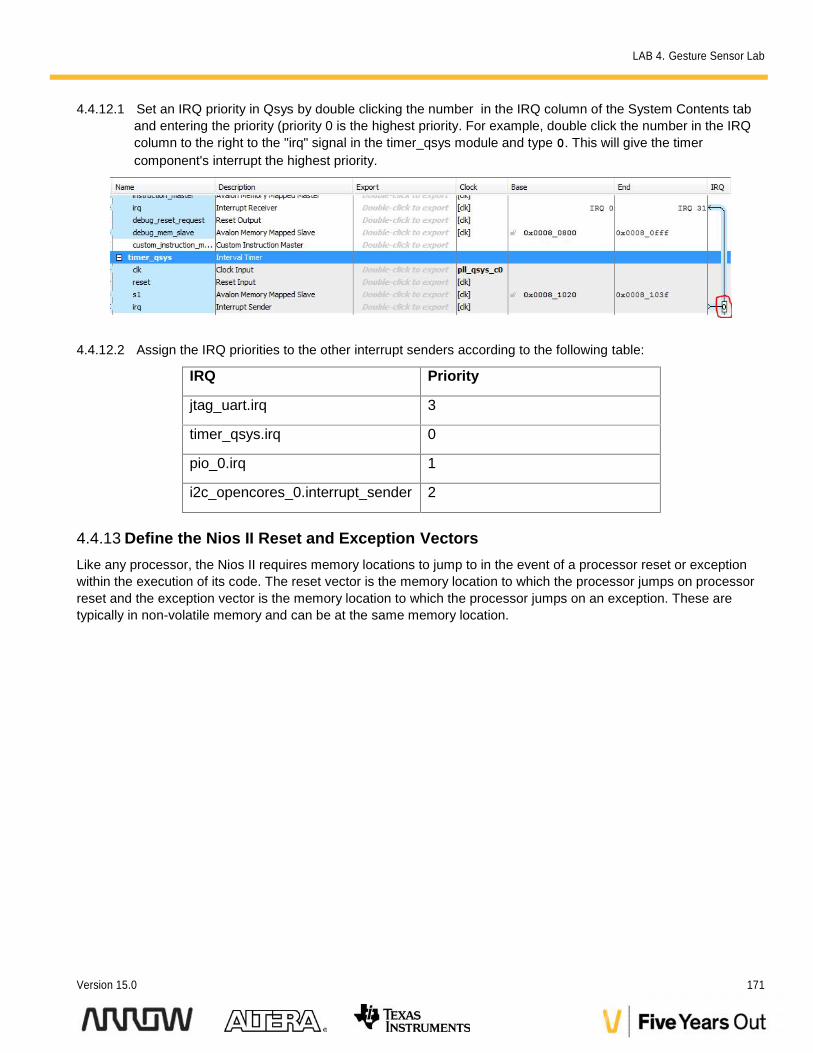
4.4.12.1 Set an IRQ priority in Qsys by double clicking the number in the IRQ column of the System Contents taband entering the priority (priority 0 is the highest priority. For example, double click the number in the IRQcolumn to the right to the "irq" signal in the timer_qsys module and type 0. This will give the timercomponent's interrupt the highest priority.
4.4.12.2 Assign the IRQ priorities to the other interrupt senders according to the following table:
IRQ Priority
jtag_uart.irq 3
timer_qsys.irq 0
pio_0.irq 1
i2c_opencores_0.interrupt_sender 2
4.4.13 Define the Nios II Reset and Exception VectorsLike any processor, the Nios II requires memory locations to jump to in the event of a processor reset or exceptionwithin the execution of its code. The reset vector is the memory location to which the processor jumps on processorreset and the exception vector is the memory location to which the processor jumps on an exception. These aretypically in non-volatile memory and can be at the same memory location.
LAB 4. Gesture Sensor Lab
172 Max10 DECA Workshop Manual
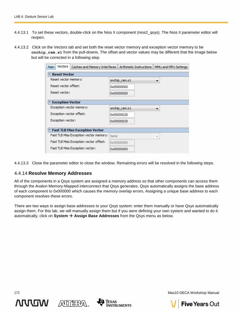
4.4.13.1 To set these vectors, double-click on the Nios II component (nios2_qsys). The Nios II parameter editor willreopen.
4.4.13.2 Click on the Vectors tab and set both the reset vector memory and exception vector memory to beonchip_ram.s1 from the pull-downs. The offset and vector values may be different that the image belowbut will be corrected in a following step.
4.4.13.3 Close the parameter editor to close the window. Remaining errors will be resolved in the following steps.
4.4.14 Resolve Memory AddressesAll of the components in a Qsys system are assigned a memory address so that other components can access themthrough the Avalon Memory-Mapped interconnect that Qsys generates. Qsys automatically assigns the base addressof each component to 0x000000 which causes the memory overlap errors. Assigning a unique base address to eachcomponent resolves these errors.
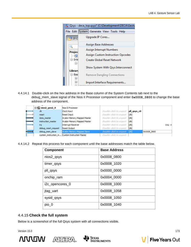
There are two ways to assign base addresses to your Qsys system: enter them manually or have Qsys automaticallyassign them. For this lab, we will manually assign them but if you were defining your own system and wanted to do itautomatically, click on System Assign Base Addresses from the Qsys menu as below.
LAB 4. Gesture Sensor Lab
Version 15.0 173
4.4.14.1 Double-click on the hex address in the Base column of the System Contents tab next to thedebug_mem_slave signal of the Nios II Processor component and enter 0x0008_0800 to change the baseaddress of the component.
4.4.14.2 Repeat this process for each component until the base addresses match the table below.
Component Base Address
nios2_qsys 0x0008_0800
timer_qsys 0x0008_1020
pll_qsys 0x0000_0000
onchip_ram 0x0004_0000
i2c_opencores_0 0x0008_1000
jtag_uart 0x0008_1058
sysid_qsys 0x0008_1050
pio_0 0x0008_1040
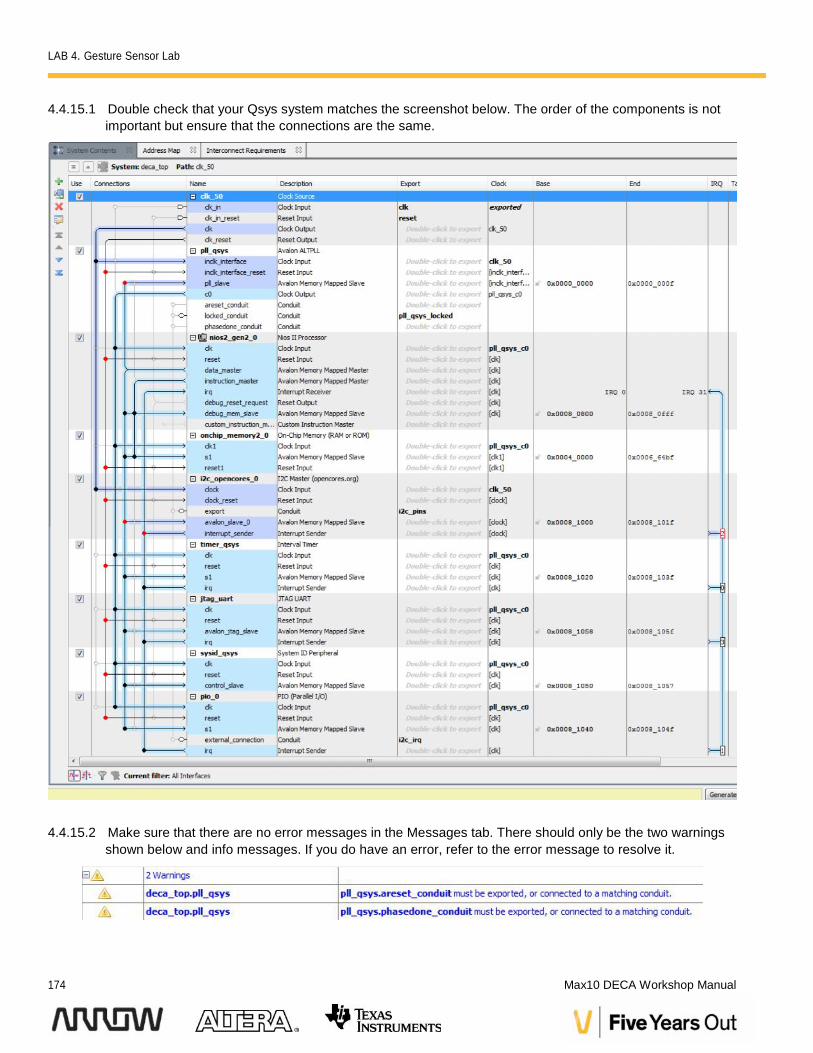
4.4.15 Check the full systemBelow is a screenshot of the full Qsys system with all connections visible.
LAB 4. Gesture Sensor Lab
174 Max10 DECA Workshop Manual
4.4.15.1 Double check that your Qsys system matches the screenshot below. The order of the components is notimportant but ensure that the connections are the same.
4.4.15.2 Make sure that there are no error messages in the Messages tab. There should only be the two warningsshown below and info messages. If you do have an error, refer to the error message to resolve it.
LAB 4. Gesture Sensor Lab
Version 15.0 175
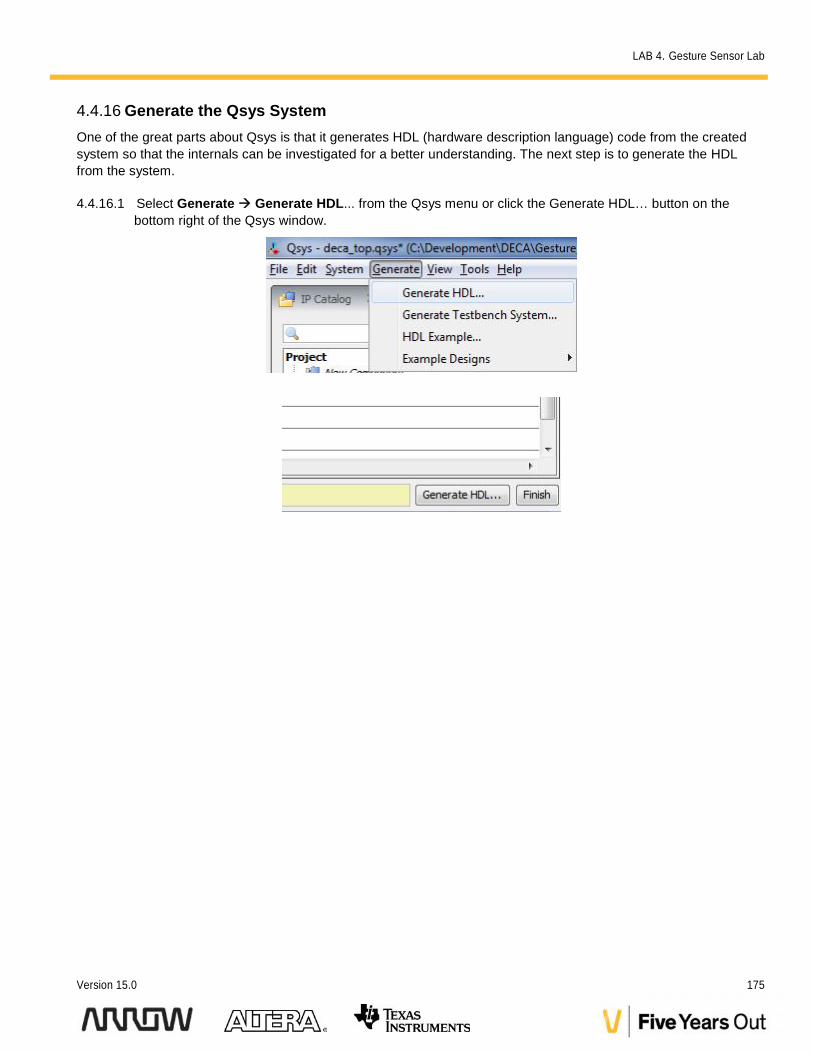
4.4.16 Generate the Qsys SystemOne of the great parts about Qsys is that it generates HDL (hardware description language) code from the createdsystem so that the internals can be investigated for a better understanding. The next step is to generate the HDLfrom the system.
4.4.16.1 Select Generate Generate HDL... from the Qsys menu or click the Generate HDL… button on thebottom right of the Qsys window.
LAB 4. Gesture Sensor Lab
176 Max10 DECA Workshop Manual
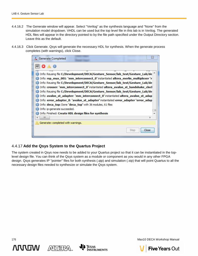
4.4.16.2 The Generate window will appear. Select "Verilog" as the synthesis language and "None" from thesimulation model dropdown. VHDL can be used but the top level file in this lab is in Verilog. The generatedHDL files will appear in the directory pointed to by the file path specified under the Output Directory section.Leave this as the default.
4.4.16.3 Click Generate. Qsys will generate the necessary HDL for synthesis. When the generate processcompletes (with warnings), click Close.
4.4.17 Add the Qsys System to the Quartus ProjectThe system created in Qsys now needs to be added to your Quartus project so that it can be instantiated in the top-level design file. You can think of the Qsys system as a module or component as you would in any other FPGAdesign. Qsys generates IP "pointer" files for both synthesis (.qip) and simulation (.sip) that will point Quartus to all thenecessary design files needed to synthesize or simulate the Qsys system.
LAB 4. Gesture Sensor Lab
Version 15.0 177
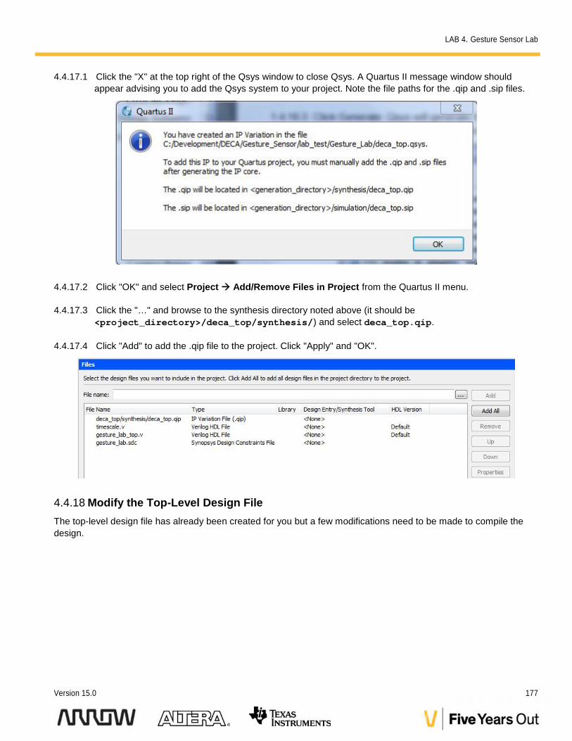
4.4.17.1 Click the "X" at the top right of the Qsys window to close Qsys. A Quartus II message window shouldappear advising you to add the Qsys system to your project. Note the file paths for the .qip and .sip files.
4.4.17.2 Click "OK" and select Project Add/Remove Files in Project from the Quartus II menu.
4.4.17.3 Click the "…" and browse to the synthesis directory noted above (it should be<project_directory>/deca_top/synthesis/) and select deca_top.qip.
4.4.17.4 Click "Add" to add the .qip file to the project. Click "Apply" and "OK".
4.4.18 Modify the Top-Level Design FileThe top-level design file has already been created for you but a few modifications need to be made to compile thedesign.
LAB 4. Gesture Sensor Lab
178 Max10 DECA Workshop Manual
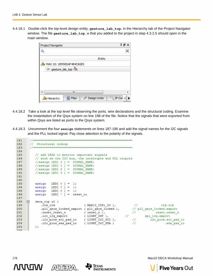
4.4.18.1 Double-click the top-level design entity, gesture_lab_top, in the Hierarchy tab of the Project Navigatorwindow. The file gesture_lab_top.v that you added to the project in step 4.3.2.5 should open in themain window.
4.4.18.2 Take a look at the top level file observing the ports, wire declarations and the structural coding. Examinethe instantiation of the Qsys system on line 198 of the file. Notice that the signals that were exported fromwithin Qsys are listed as ports to the Qsys system.
4.4.18.3 Uncomment the four assign statements on lines 187-190 and add the signal names for the I2C signalsand the PLL locked signal. Pay close attention to the polarity of the signals.
LAB 4. Gesture Sensor Lab
Version 15.0 179
4.4.18.4 Click File Save All from the Quartus II menu.
4.4.19 Import Pin AssignmentsNormally, the pin assignments for a design would need to be entered manually depending on the board-levelimplementation. Since the pins on the DECA board are fixed, we can import the pin assignments automatically.
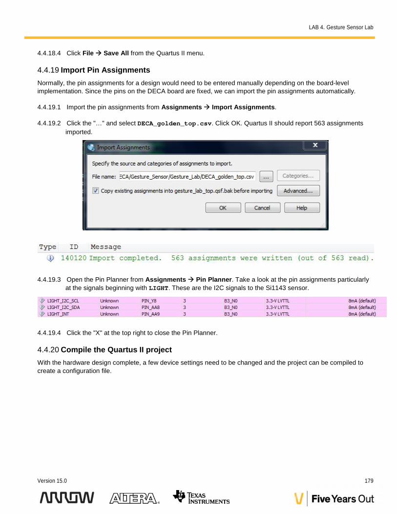
4.4.19.1 Import the pin assignments from Assignments Import Assignments.
4.4.19.2 Click the "…" and select DECA_golden_top.csv. Click OK. Quartus II should report 563 assignmentsimported.
4.4.19.3 Open the Pin Planner from Assignments Pin Planner. Take a look at the pin assignments particularlyat the signals beginning with LIGHT. These are the I2C signals to the Si1143 sensor.
4.4.19.4 Click the "X" at the top right to close the Pin Planner.
4.4.20 Compile the Quartus II projectWith the hardware design complete, a few device settings need to be changed and the project can be compiled tocreate a configuration file.
LAB 4. Gesture Sensor Lab
180 Max10 DECA Workshop Manual
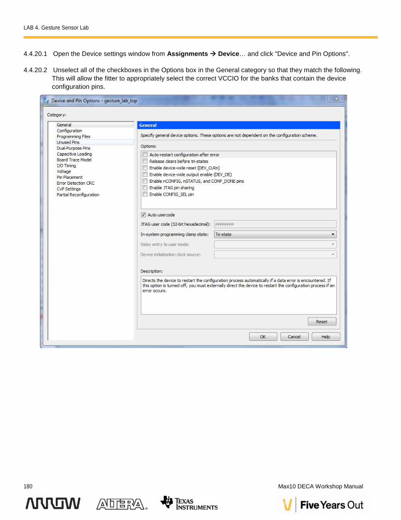
4.4.20.1 Open the Device settings window from Assignments Device… and click "Device and Pin Options".
4.4.20.2 Unselect all of the checkboxes in the Options box in the General category so that they match the following.This will allow the fitter to appropriately select the correct VCCIO for the banks that contain the deviceconfiguration pins.
LAB 4. Gesture Sensor Lab
Version 15.0 181
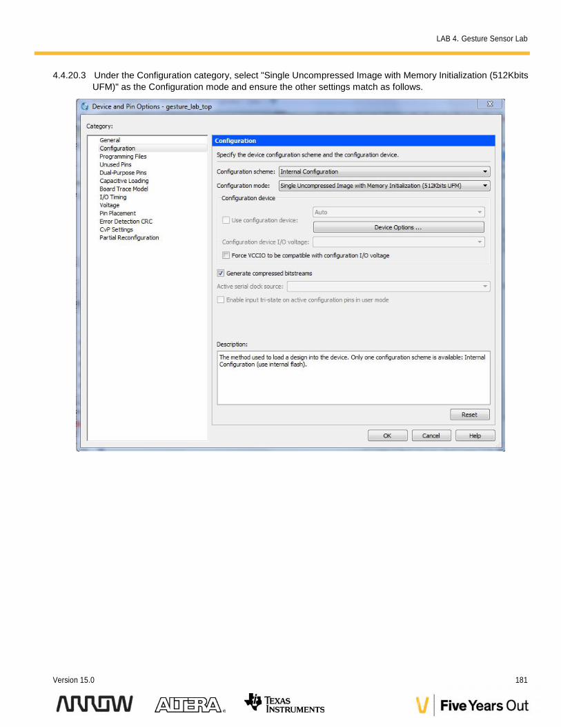
4.4.20.3 Under the Configuration category, select "Single Uncompressed Image with Memory Initialization (512KbitsUFM)" as the Configuration mode and ensure the other settings match as follows.
LAB 4. Gesture Sensor Lab
182 Max10 DECA Workshop Manual
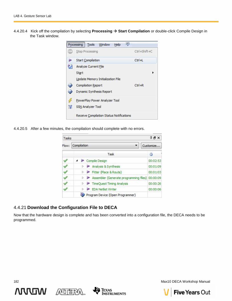
4.4.20.4 Kick off the compilation by selecting Processing Start Compilation or double-click Compile Design inthe Task window.
4.4.20.5 After a few minutes, the compilation should complete with no errors.
4.4.21 Download the Configuration File to DECANow that the hardware design is complete and has been converted into a configuration file, the DECA needs to beprogrammed.
LAB 4. Gesture Sensor Lab
Version 15.0 183
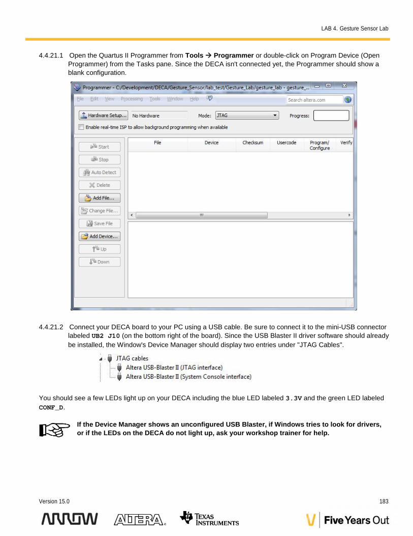
4.4.21.1 Open the Quartus II Programmer from Tools Programmer or double-click on Program Device (OpenProgrammer) from the Tasks pane. Since the DECA isn't connected yet, the Programmer should show ablank configuration.
4.4.21.2 Connect your DECA board to your PC using a USB cable. Be sure to connect it to the mini-USB connectorlabeled UB2 J10 (on the bottom right of the board). Since the USB Blaster II driver software should alreadybe installed, the Window's Device Manager should display two entries under "JTAG Cables".
You should see a few LEDs light up on your DECA including the blue LED labeled 3.3V and the green LED labeledCONF_D.
If the Device Manager shows an unconfigured USB Blaster, if Windows tries to look for drivers,or if the LEDs on the DECA do not light up, ask your workshop trainer for help.
LAB 4. Gesture Sensor Lab
184 Max10 DECA Workshop Manual
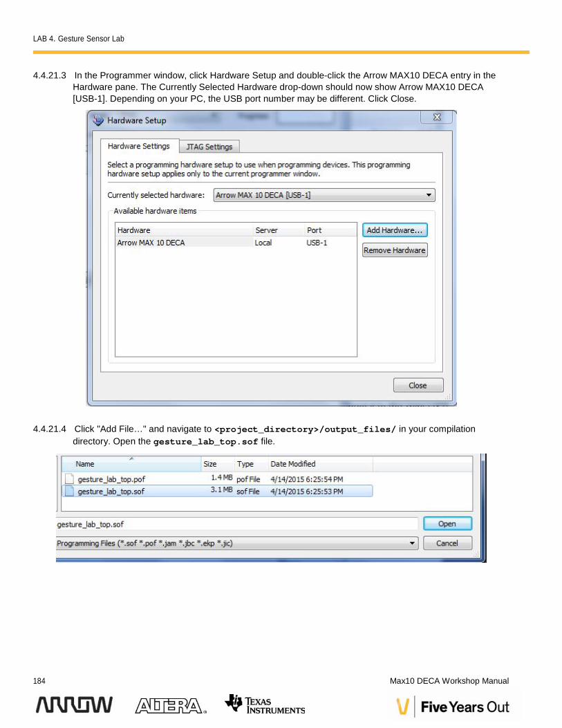
4.4.21.3 In the Programmer window, click Hardware Setup and double-click the Arrow MAX10 DECA entry in theHardware pane. The Currently Selected Hardware drop-down should now show Arrow MAX10 DECA[USB-1]. Depending on your PC, the USB port number may be different. Click Close.
4.4.21.4 Click "Add File…" and navigate to <project_directory>/output_files/ in your compilationdirectory. Open the gesture_lab_top.sof file.
LAB 4. Gesture Sensor Lab
Version 15.0 185
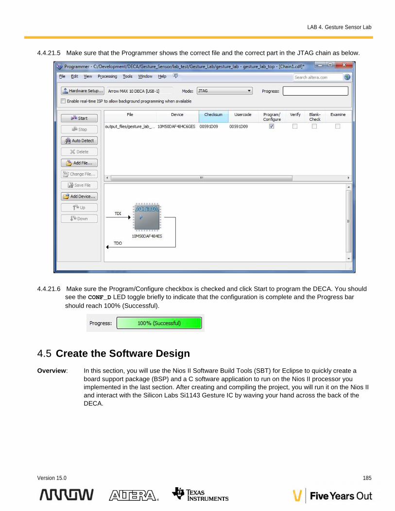
4.4.21.5 Make sure that the Programmer shows the correct file and the correct part in the JTAG chain as below.
4.4.21.6 Make sure the Program/Configure checkbox is checked and click Start to program the DECA. You shouldsee the CONF_D LED toggle briefly to indicate that the configuration is complete and the Progress barshould reach 100% (Successful).
4.5 Create the Software DesignOverview: In this section, you will use the Nios II Software Build Tools (SBT) for Eclipse to quickly create a
board support package (BSP) and a C software application to run on the Nios II processor youimplemented in the last section. After creating and compiling the project, you will run it on the Nios IIand interact with the Silicon Labs Si1143 Gesture IC by waving your hand across the back of theDECA.
LAB 4. Gesture Sensor Lab
186 Max10 DECA Workshop Manual
4.5.1 Start Nios II Software Build Tools for Eclipse
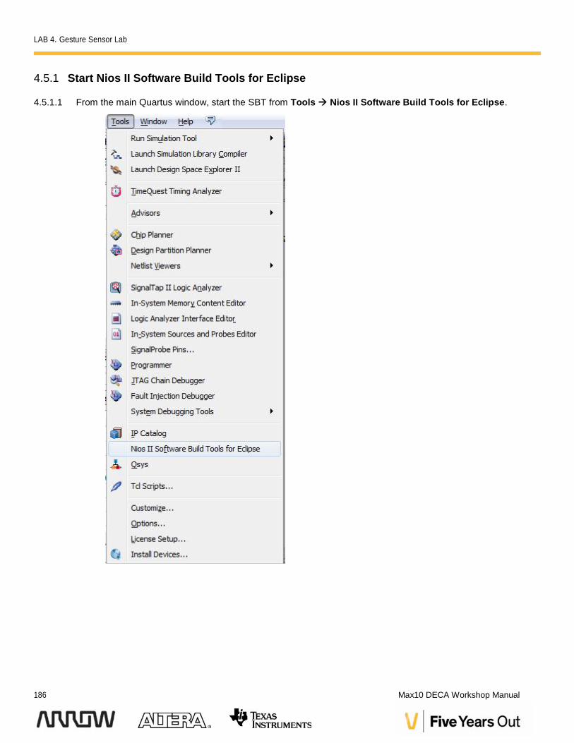
4.5.1.1 From the main Quartus window, start the SBT from Tools Nios II Software Build Tools for Eclipse.
LAB 4. Gesture Sensor Lab
Version 15.0 187
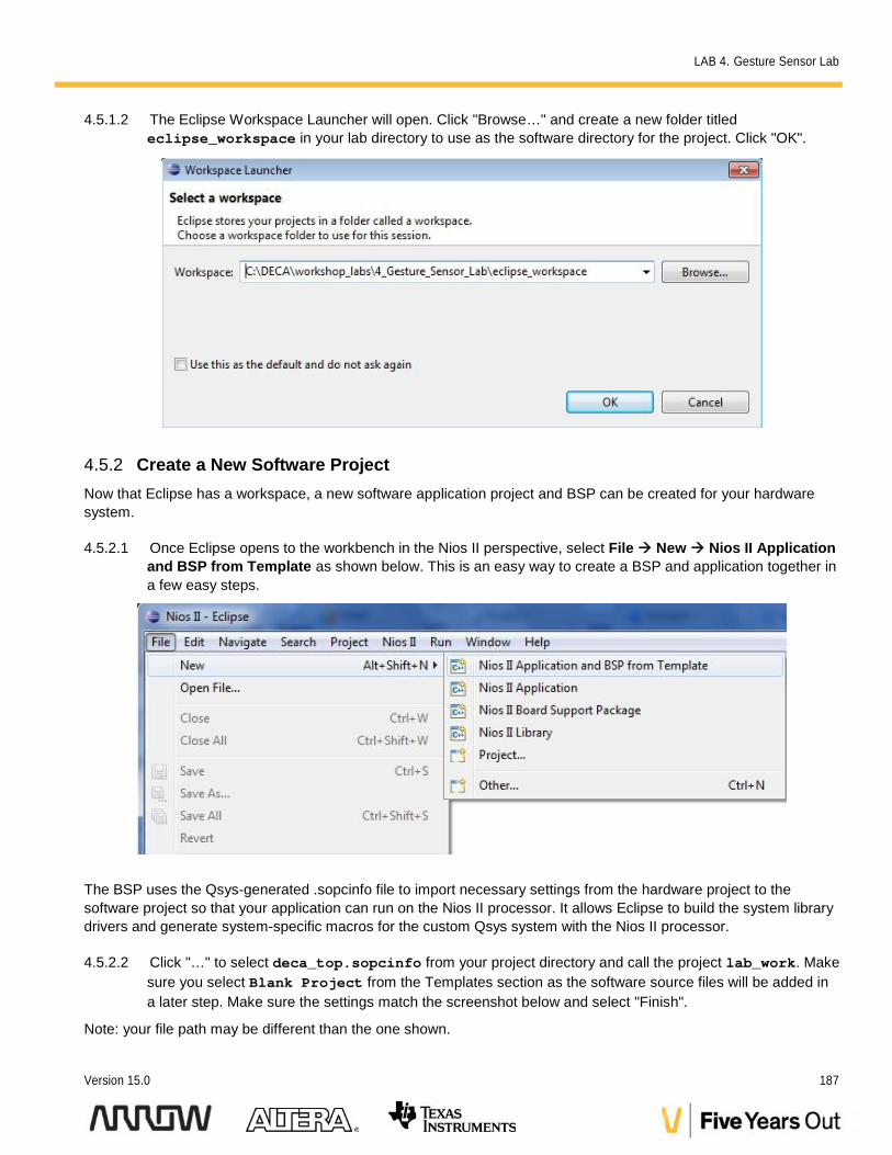
4.5.1.2 The Eclipse Workspace Launcher will open. Click "Browse…" and create a new folder titledeclipse_workspace in your lab directory to use as the software directory for the project. Click "OK".
4.5.2 Create a New Software ProjectNow that Eclipse has a workspace, a new software application project and BSP can be created for your hardwaresystem.
4.5.2.1 Once Eclipse opens to the workbench in the Nios II perspective, select File New Nios II Applicationand BSP from Template as shown below. This is an easy way to create a BSP and application together ina few easy steps.
The BSP uses the Qsys-generated .sopcinfo file to import necessary settings from the hardware project to thesoftware project so that your application can run on the Nios II processor. It allows Eclipse to build the system librarydrivers and generate system-specific macros for the custom Qsys system with the Nios II processor.
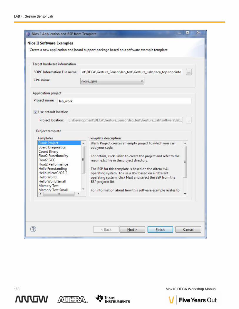
4.5.2.2 Click "…" to select deca_top.sopcinfo from your project directory and call the project lab_work. Makesure you select Blank Project from the Templates section as the software source files will be added ina later step. Make sure the settings match the screenshot below and select "Finish".
Note: your file path may be different than the one shown.
LAB 4. Gesture Sensor Lab
188 Max10 DECA Workshop Manual
LAB 4. Gesture Sensor Lab
Version 15.0 189
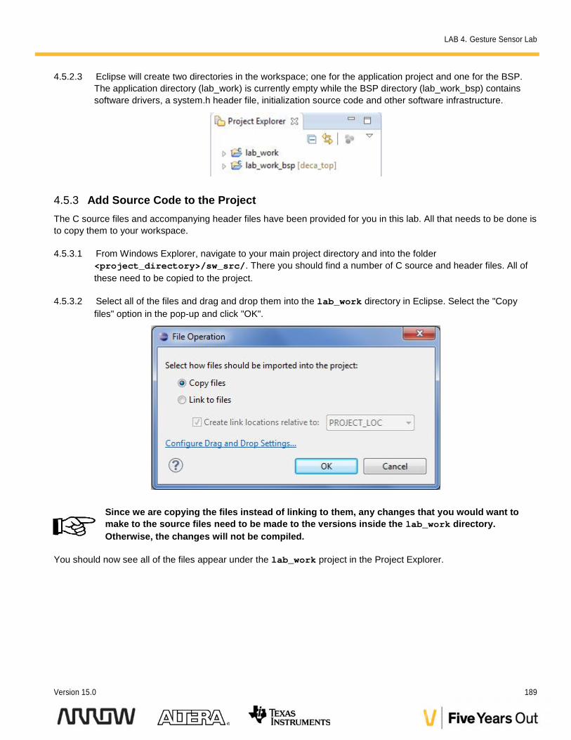
4.5.2.3 Eclipse will create two directories in the workspace; one for the application project and one for the BSP.The application directory (lab_work) is currently empty while the BSP directory (lab_work_bsp) containssoftware drivers, a system.h header file, initialization source code and other software infrastructure.
4.5.3 Add Source Code to the ProjectThe C source files and accompanying header files have been provided for you in this lab. All that needs to be done isto copy them to your workspace.
4.5.3.1 From Windows Explorer, navigate to your main project directory and into the folder<project_directory>/sw_src/. There you should find a number of C source and header files. All ofthese need to be copied to the project.
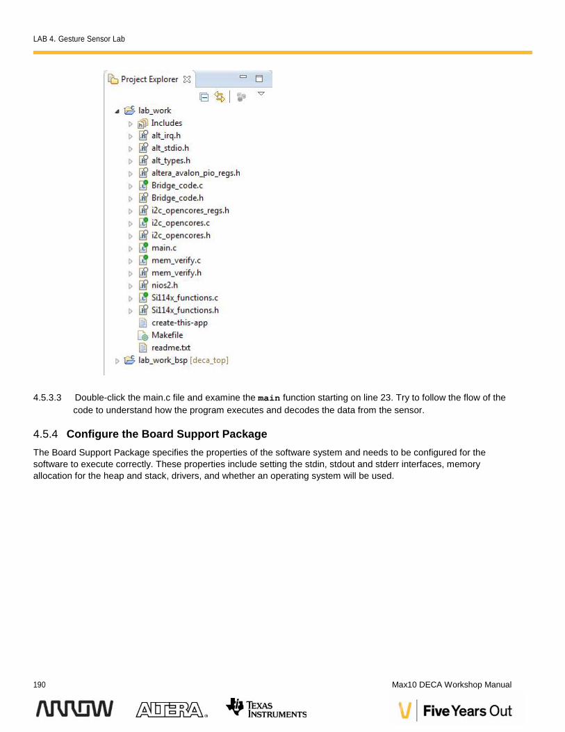
4.5.3.2 Select all of the files and drag and drop them into the lab_work directory in Eclipse. Select the "Copyfiles" option in the pop-up and click "OK".
Since we are copying the files instead of linking to them, any changes that you would want tomake to the source files need to be made to the versions inside the lab_work directory.Otherwise, the changes will not be compiled.
You should now see all of the files appear under the lab_work project in the Project Explorer.
LAB 4. Gesture Sensor Lab
190 Max10 DECA Workshop Manual
4.5.3.3 Double-click the main.c file and examine the main function starting on line 23. Try to follow the flow of thecode to understand how the program executes and decodes the data from the sensor.
4.5.4 Configure the Board Support PackageThe Board Support Package specifies the properties of the software system and needs to be configured for thesoftware to execute correctly. These properties include setting the stdin, stdout and stderr interfaces, memoryallocation for the heap and stack, drivers, and whether an operating system will be used.
LAB 4. Gesture Sensor Lab
Version 15.0 191
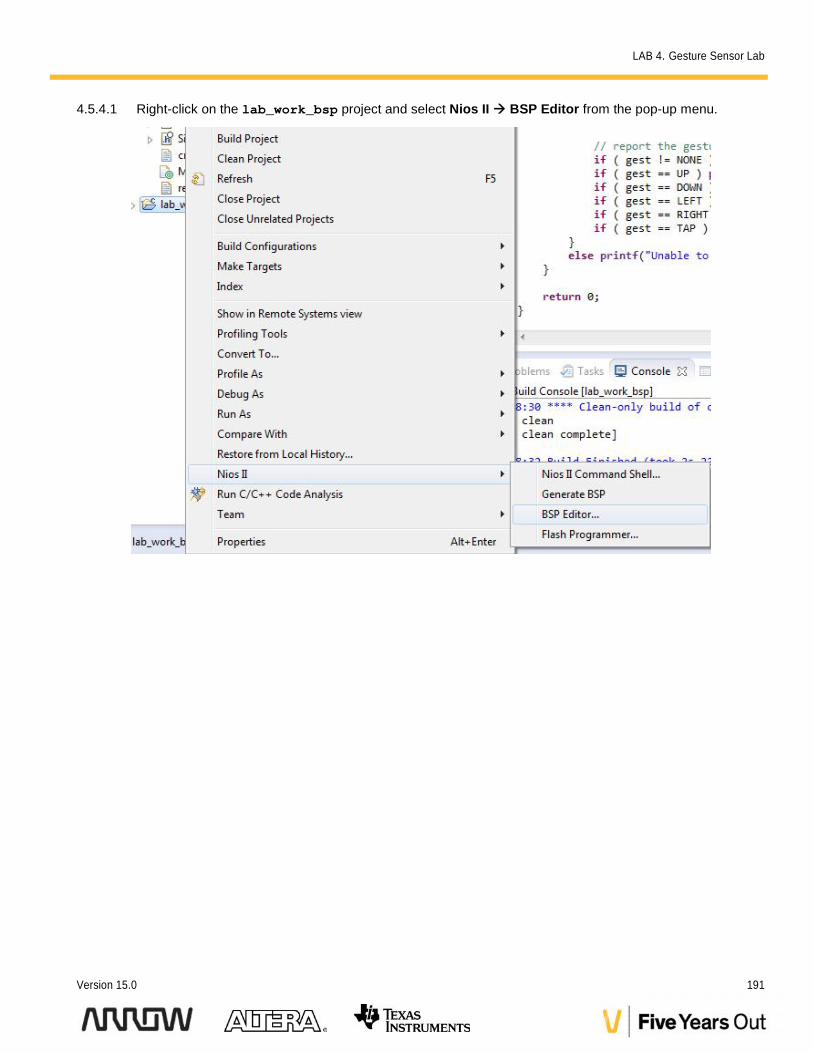
4.5.4.1 Right-click on the lab_work_bsp project and select Nios II BSP Editor from the pop-up menu.
LAB 4. Gesture Sensor Lab
192 Max10 DECA Workshop Manual
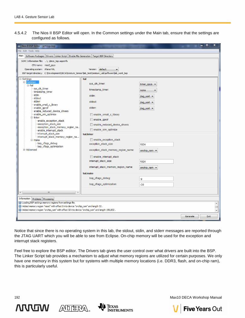
4.5.4.2 The Nios II BSP Editor will open. In the Common settings under the Main tab, ensure that the settings areconfigured as follows.
Notice that since there is no operating system in this lab, the stdout, stdin, and stderr messages are reported throughthe JTAG UART which you will be able to see from Eclipse. On-chip memory will be used for the exception andinterrupt stack registers.
Feel free to explore the BSP editor. The Drivers tab gives the user control over what drivers are built into the BSP.The Linker Script tab provides a mechanism to adjust what memory regions are utilized for certain purposes. We onlyhave one memory in this system but for systems with multiple memory locations (i.e. DDR3, flash, and on-chip ram),this is particularly useful.
LAB 4. Gesture Sensor Lab
Version 15.0 193
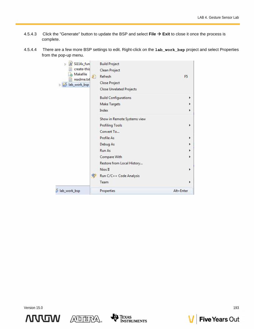
4.5.4.3 Click the "Generate" button to update the BSP and select File Exit to close it once the process iscomplete.
4.5.4.4 There are a few more BSP settings to edit. Right-click on the lab_work_bsp project and select Propertiesfrom the pop-up menu.
LAB 4. Gesture Sensor Lab
194 Max10 DECA Workshop Manual
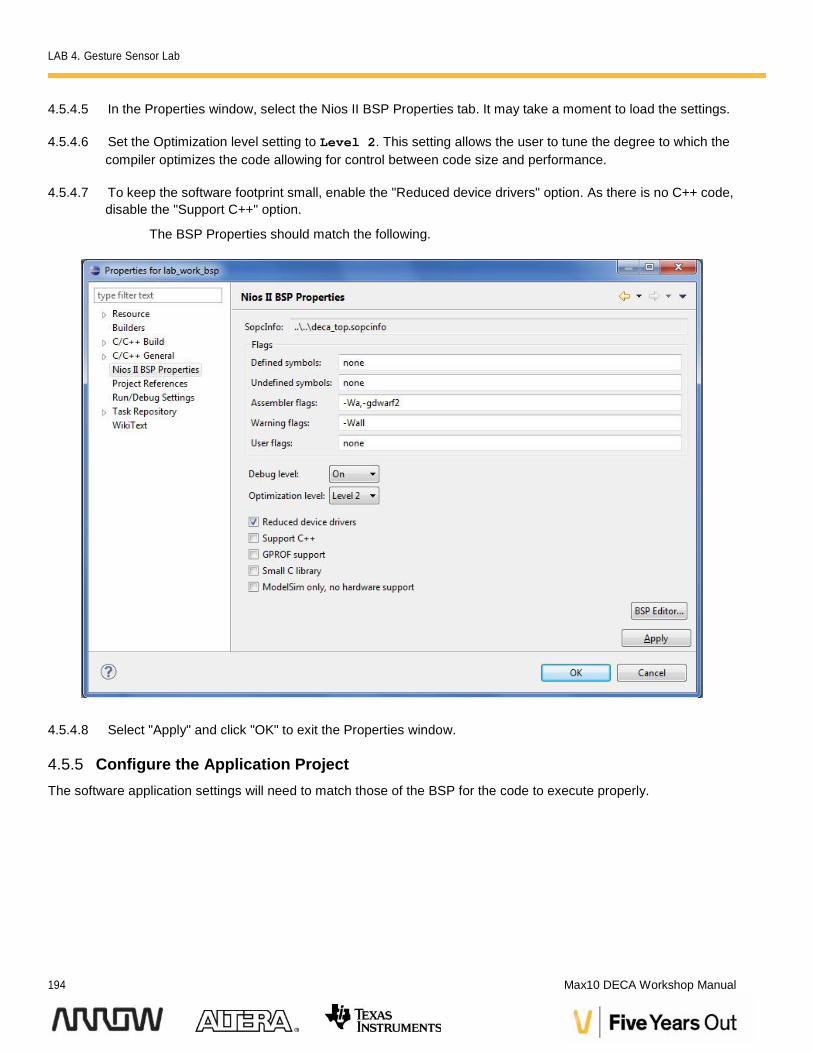
4.5.4.5 In the Properties window, select the Nios II BSP Properties tab. It may take a moment to load the settings.
4.5.4.6 Set the Optimization level setting to Level 2. This setting allows the user to tune the degree to which thecompiler optimizes the code allowing for control between code size and performance.
4.5.4.7 To keep the software footprint small, enable the "Reduced device drivers" option. As there is no C++ code,disable the "Support C++" option.
The BSP Properties should match the following.
4.5.4.8 Select "Apply" and click "OK" to exit the Properties window.
4.5.5 Configure the Application ProjectThe software application settings will need to match those of the BSP for the code to execute properly.
LAB 4. Gesture Sensor Lab
Version 15.0 195
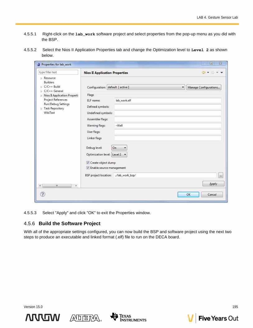
4.5.5.1 Right-click on the lab_work software project and select properties from the pop-up menu as you did withthe BSP.
4.5.5.2 Select the Nios II Application Properties tab and change the Optimization level to Level 2 as shownbelow.
4.5.5.3 Select "Apply" and click "OK" to exit the Properties window.
4.5.6 Build the Software ProjectWith all of the appropriate settings configured, you can now build the BSP and software project using the next twosteps to produce an executable and linked format (.elf) file to run on the DECA board.
LAB 4. Gesture Sensor Lab
196 Max10 DECA Workshop Manual
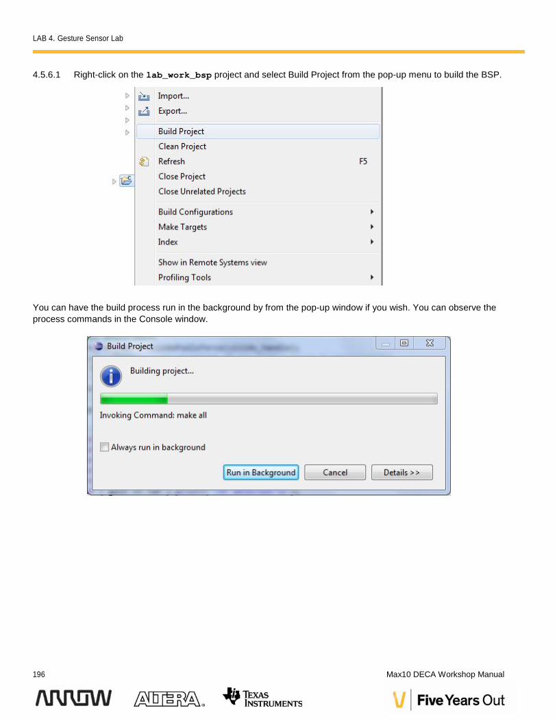
4.5.6.1 Right-click on the lab_work_bsp project and select Build Project from the pop-up menu to build the BSP.
You can have the build process run in the background by from the pop-up window if you wish. You can observe theprocess commands in the Console window.
LAB 4. Gesture Sensor Lab
Version 15.0 197
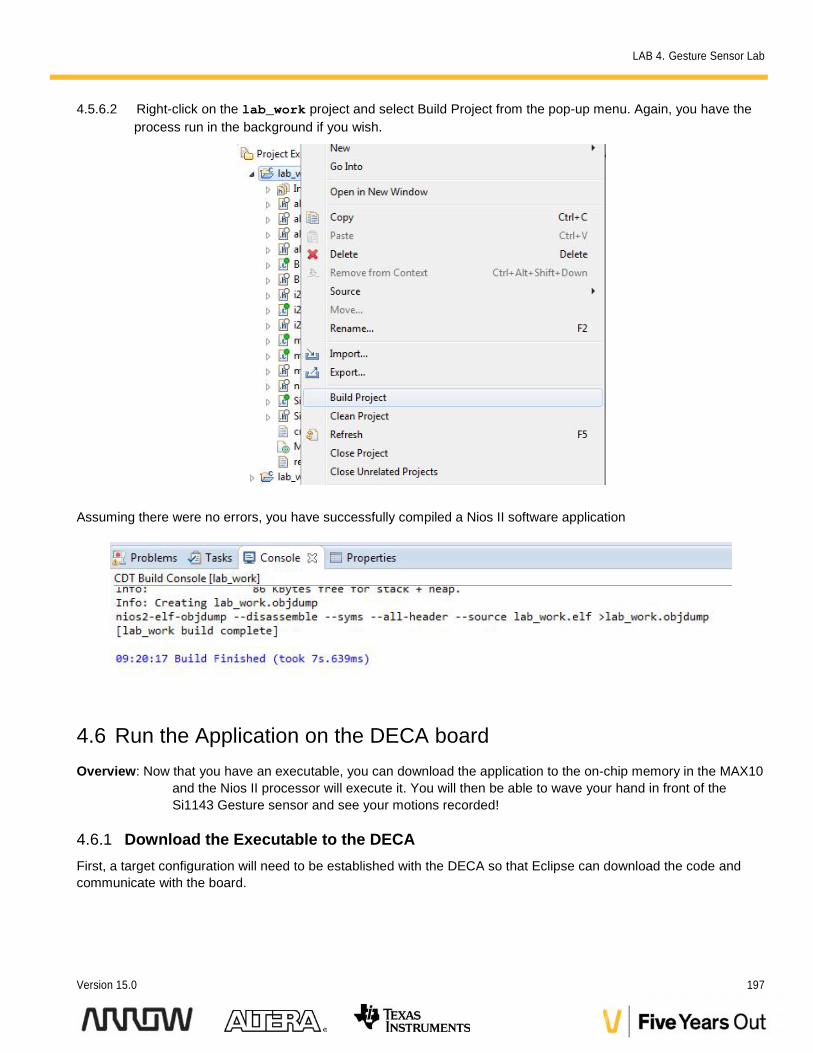
4.5.6.2 Right-click on the lab_work project and select Build Project from the pop-up menu. Again, you have theprocess run in the background if you wish.
Assuming there were no errors, you have successfully compiled a Nios II software application
4.6 Run the Application on the DECA boardOverview: Now that you have an executable, you can download the application to the on-chip memory in the MAX10
and the Nios II processor will execute it. You will then be able to wave your hand in front of theSi1143 Gesture sensor and see your motions recorded!
4.6.1 Download the Executable to the DECAFirst, a target configuration will need to be established with the DECA so that Eclipse can download the code andcommunicate with the board.
LAB 4. Gesture Sensor Lab
198 Max10 DECA Workshop Manual
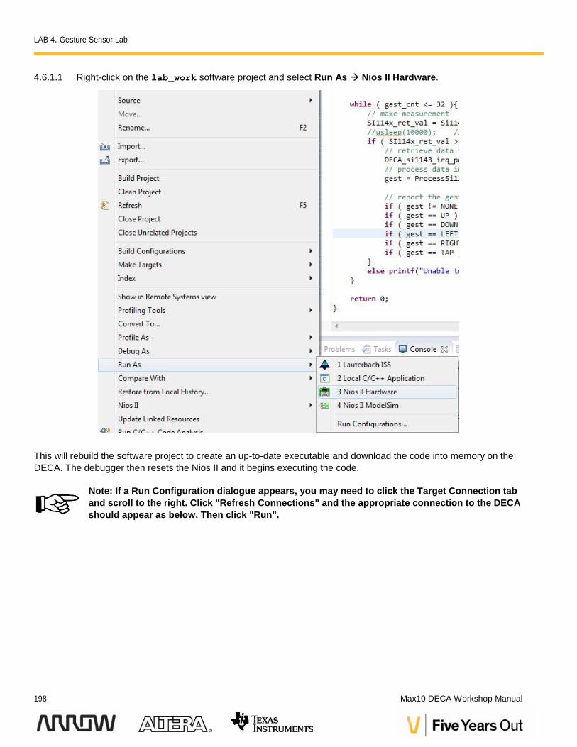
4.6.1.1 Right-click on the lab_work software project and select Run As Nios II Hardware.
This will rebuild the software project to create an up-to-date executable and download the code into memory on theDECA. The debugger then resets the Nios II and it begins executing the code.
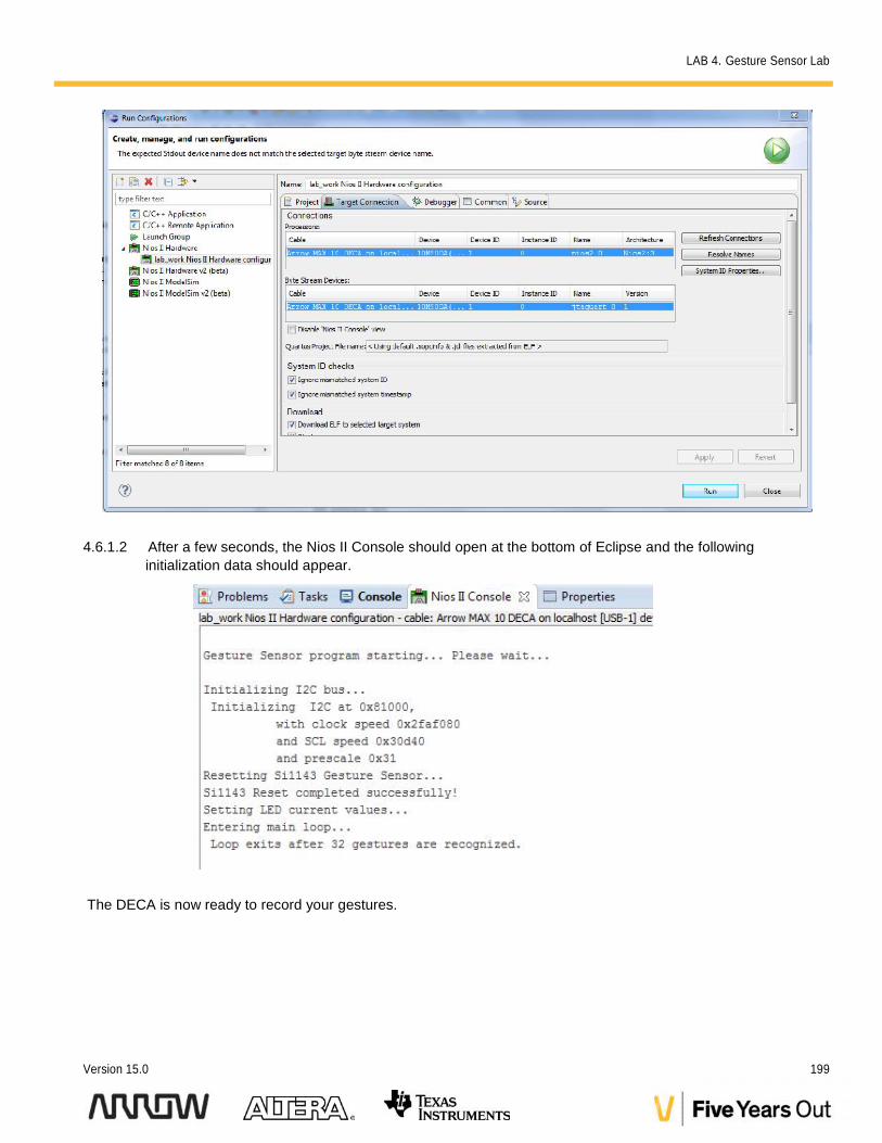
Note: If a Run Configuration dialogue appears, you may need to click the Target Connection taband scroll to the right. Click "Refresh Connections" and the appropriate connection to the DECAshould appear as below. Then click "Run".
LAB 4. Gesture Sensor Lab
Version 15.0 199
4.6.1.2 After a few seconds, the Nios II Console should open at the bottom of Eclipse and the followinginitialization data should appear.
The DECA is now ready to record your gestures.
LAB 4. Gesture Sensor Lab
200 Max10 DECA Workshop Manual
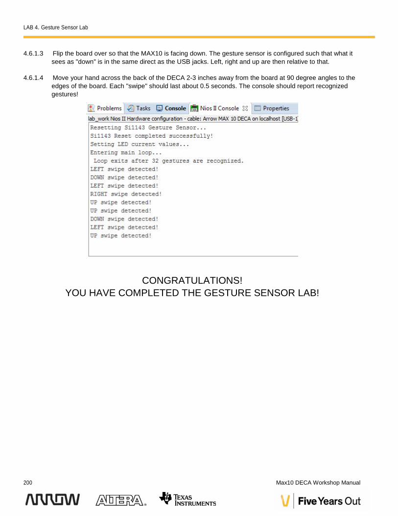
4.6.1.3 Flip the board over so that the MAX10 is facing down. The gesture sensor is configured such that what itsees as "down" is in the same direct as the USB jacks. Left, right and up are then relative to that.
4.6.1.4 Move your hand across the back of the DECA 2-3 inches away from the board at 90 degree angles to theedges of the board. Each "swipe" should last about 0.5 seconds. The console should report recognizedgestures!
CONGRATULATIONS!YOU HAVE COMPLETED THE GESTURE SENSOR LAB!