Embed Size (px)
Citation preview
FEKO
Getting Started
Manual
Suite 5.1
December 2005
Copyright 1998 – 2005: EM Software & Systems-S.A. (Pty) Ltd32 Techno Avenue, Technopark, Stellenbosch, 7600, South AfricaTel: +27-21-880-1880, Fax: +27-21-880-1936E-Mail: [email protected]: http://www.feko.info
CONTENTS i
Contents
1 Introduction 1-1
1.1 FEKO components . . . . . . . . . . . . . . . . . . . . . . . . . . . . 1-2
1.2 Using FEKO LITE instead of the full version . . . . . . . . . . . . . 1-2
1.3 Installing the full version after using FEKO LITE . . . . . . . . . . . 1-3
1.4 Contacting your distributor or EMSS . . . . . . . . . . . . . . . . . . 1-3
1.5 Updates to the documentation . . . . . . . . . . . . . . . . . . . . . . 1-3
2 Installation of FEKO 2-1
2.1 Introduction . . . . . . . . . . . . . . . . . . . . . . . . . . . . . . . . 2-1
2.2 MS Windows installation . . . . . . . . . . . . . . . . . . . . . . . . . 2-1
2.2.1 System requirements . . . . . . . . . . . . . . . . . . . . . . . . 2-2
2.2.2 Installing FEKO . . . . . . . . . . . . . . . . . . . . . . . . . . 2-2
2.2.3 Installing FEKO in silent mode using the installation executable 2-3
2.2.4 Installing FEKO in silent mode using the MSI database . . . . 2-4
2.2.5 Obtaining the FEKO licence file . . . . . . . . . . . . . . . . . 2-5
2.3 UNIX / Linux workstation installations . . . . . . . . . . . . . . . . . 2-5
2.3.1 Supported platforms . . . . . . . . . . . . . . . . . . . . . . . . 2-5
2.3.2 Installation . . . . . . . . . . . . . . . . . . . . . . . . . . . . . 2-6
2.4 Floating licences . . . . . . . . . . . . . . . . . . . . . . . . . . . . . . 2-8
2.4.1 Concept of floating licences and general comments . . . . . . . 2-8
2.4.2 Floating licence server installation and maintenance (Windows) 2-9
2.4.3 Floating licence server installation and maintenance (UNIX) . 2-11
2.5 Setup of remote launching . . . . . . . . . . . . . . . . . . . . . . . . 2-12
2.6 Adobe Reader installation . . . . . . . . . . . . . . . . . . . . . . . . 2-14
December 2005 FEKO Getting Started

ii CONTENTS
3 Rectangular horn antenna example 3-1
3.1 Example overview . . . . . . . . . . . . . . . . . . . . . . . . . . . . . 3-1
3.2 Creation of the geometry in CADFEKO . . . . . . . . . . . . . . . . 3-1
3.2.1 The contents tree . . . . . . . . . . . . . . . . . . . . . . . . . . 3-3
3.2.2 The details tree . . . . . . . . . . . . . . . . . . . . . . . . . . . 3-3
3.3 Setting the solution control . . . . . . . . . . . . . . . . . . . . . . . . 3-4
3.4 Obtaining a Solution . . . . . . . . . . . . . . . . . . . . . . . . . . . 3-6
3.5 Viewing the model and results . . . . . . . . . . . . . . . . . . . . . . 3-6
3.5.1 Model validation . . . . . . . . . . . . . . . . . . . . . . . . . . 3-6
3.5.2 Near field results . . . . . . . . . . . . . . . . . . . . . . . . . . 3-8
3.5.3 Far field results . . . . . . . . . . . . . . . . . . . . . . . . . . . 3-10
3.6 Closing remarks . . . . . . . . . . . . . . . . . . . . . . . . . . . . . . 3-12
4 Patch antenna example 4-1
4.1 Example overview . . . . . . . . . . . . . . . . . . . . . . . . . . . . . 4-1
4.2 Creation of the geometry in CADFEKO . . . . . . . . . . . . . . . . 4-1
4.3 Mesh creation . . . . . . . . . . . . . . . . . . . . . . . . . . . . . . . 4-4
4.4 Setting the solution control . . . . . . . . . . . . . . . . . . . . . . . . 4-6
4.5 Obtaining a solution . . . . . . . . . . . . . . . . . . . . . . . . . . . 4-9
4.6 Visualisation of results . . . . . . . . . . . . . . . . . . . . . . . . . . 4-9
4.7 Closing remarks . . . . . . . . . . . . . . . . . . . . . . . . . . . . . . 4-10
5 EMC coupling example 5-1
5.1 Example overview . . . . . . . . . . . . . . . . . . . . . . . . . . . . . 5-1
5.2 Creation of the geometry in CADFEKO . . . . . . . . . . . . . . . . 5-1
5.3 Mesh creation . . . . . . . . . . . . . . . . . . . . . . . . . . . . . . . 5-4
5.4 Setting the solution control . . . . . . . . . . . . . . . . . . . . . . . . 5-4
5.5 Obtaining a solution . . . . . . . . . . . . . . . . . . . . . . . . . . . 5-7
5.6 Visualisation of results . . . . . . . . . . . . . . . . . . . . . . . . . . 5-7
5.7 Closing remarks . . . . . . . . . . . . . . . . . . . . . . . . . . . . . . 5-8
EM Software & Systems-S.A. (Pty) Ltd December 2005

CONTENTS iii
6 More examples 6-1
Index I-1
December 2005 FEKO Getting Started

INTRODUCTION 1-1
1 Introduction
The first section in this Getting Started manual discusses the installation of FEKO underMS Windows on PC’s and on UNIX workstations. Note that the graphical user inter-face (CADFEKO, EDITFEKO and POSTFEKO) is currently only available under MSWindows and Linux.
The next sections discuss a number of simple step-by-step examples designed to guide theuser through the process of:
• Creating geometry in the CADFEKO user interface.
• Setting the appropriate electromagnetic parameters in the EDITFEKO user inter-face.
• Solving the electromagnetic problem at hand.
• Using the POSTFEKO user interface to view the model and plot solution data.
This guide contains three examples:
• The first example introduces all the components of FEKO and the basic solutionprocess. A model of a horn antenna is distributed with the FEKO suite. This modelis discussed and instructions are given for the extraction of results from this model.
• In the second example we introduce symmetry and labels and look at some meshrequirements. The second example shows the development of a FEKO model of apatch antenna on a finite sized substrate. Dielectric regions and local mesh para-meters are set for this example.
• The third example considers a simple EMC type problem and demonstrates how toset up a model in the presence of a ground plane.
These examples present a very basic introduction to FEKO. The FEKO User’s Manualshould be consulted for a broader presentation of all the features available in FEKO. (Itcan be found in the doc directory under the FEKO installation directory, or in the docdirectory on the FEKO CD and can be viewed and printed with the Adobe Reader — seesection 2.6.) New users should read at least the General comments section of the User’sManual.
Other simple examples which illustrate certain features of FEKO are discussed in theFEKO Examples Guide which may be found in the same location as the User’s Man-ual. The input files for these examples are available in the examples\CAD_input andexamples\text_input directories, respectively, under the FEKO installation directory.
December 2005 FEKO Getting Started

1-2 INTRODUCTION
1.1 FEKO components
This section gives a quick overview of the various FEKO components and their availabilityon the various platforms. Presently both pre- and post processing have to be done underMS Windows or Linux.
• The CADFEKO interface is used for geometry specification and mesh generation.
• The electromagnetic parameters are set in the EDITFEKO interface, which providesa user friendly interface to the input cards required by FEKO.
• Both the solution kernel, FEKO, and the preprocessor/mesher, PREFEKO, as wellas the adaptive frequency component, ADAPTFEKO, are available on all supportedPC and workstation platforms.
• The POSTFEKO interface is used to display the model and all the results of thesimulation.
• The support components, OPTFEKO and TIMEFEKO — used for optimisationand time domain analysis respectively — are available on all supported PC andworkstation platforms.
1.2 Using FEKO LITE instead of the full version
FEKO can be run in a mode called FEKO LITE . This is a limited version of the FEKOsuite. All the components of the suite, from the graphical user interfaces to the solver, arelimited in capability when running in this mode. Note that the LITE version of FEKOis not an evaluation version! An evaluation licence will allow the unlimited use of FEKOfor 30 days. If you are considering the purchase of FEKO, please contact your distributorfor an evaluation licence.
A licence is required to run FEKO in LITE mode. If no licence is present, FEKO willrun for a period of 30 days. The FEKO licence is stored in the file secfeko.dat in thelicense subdirectory of the FEKO installation.
A licence for the FEKO LITE mode can be requested from the FEKO website. Thelicence that will be provided will expire after 6 months, at which time a re-registrationis required. Once the registration from is filled in, it will be submitted to the distributorfor your region for processing. Once the request is processed, a licence file will be sent toyou via email.
You can register your copy of FEKO LITE at
www.feko.info/register lite
EM Software & Systems-S.A. (Pty) Ltd December 2005
INTRODUCTION 1-3
FEKO LITE is limited with respect to problem size and can therefore run only abouthalf the examples in the FEKO Examples Guide. The examples in this guide were chosenwith this in mind and only the last two examples need some modification to run themwith FEKO LITE. Only the final example in this guide can be run in FEKO LITE mode,with some minor modification.
1.3 Installing the full version after using FEKO LITE
If you have an installation of FEKO LITE, switching to the full version is simple. (Notethat the evaluation version is a full version which is limited only in the period for which itcan be used.) In order to create a FEKO licence for a computer, some information aboutthat computer is required. Execute the script request.bat in the bin subdirectory ofthe FEKO installation. This creates a file request in the license subdirectory. Editthis file to enter the information requested at the top of the file and email or fax the fileto your distributor. You will then receive a file secfeko.dat which you must copy to thelicense subdirectory of the FEKO installation (overwrite any existing files).
1.4 Contacting your distributor or EMSS
You can find the distributor for your region at
www.feko.info/contact.htm
Alternatively, for technical questions, please send email to
feko [email protected] for North Americafeko [email protected] for Europefeko [email protected] for all other regions
or, for activation codes and licence queries, to
feko [email protected] for North Americafeko [email protected] for Europefeko [email protected] for all other regions
1.5 Updates to the documentation
Changes in this manual with respect to the previous one of July 2005 (Suite 5.0) areindicated as follows:Sections that have changed from those in the previous version of the manual.Sections that were newly added to this version of the manual.
December 2005 FEKO Getting Started
INSTALLATION OF FEKO 2-1
2 Installation of FEKO
2.1 Introduction
This section describes the installation procedures for FEKO on PCs and workstations.You should be able to install the software successfully by following the on-screen instal-lation instructions. However, it is recommended that you work through the installationprocedures described here. If you have technical questions, please contact your distributor(see section 1.4).
The PC installation is for Windows NT/2000/XP (Windows 98 and ME are no longersupported). The workstation installation is for any of the major UNIX workstation plat-forms, including HP, SGI, SUN and Linux. An efficient parallel version of FEKO is alsoavailable on all these platforms (Windows, Linux and UNIX).
The installation copies the FEKO manuals to the doc subdirectory. These manuals arein PDF format and a PDF viewer, for example the Adobe Reader, is required to viewthem. The installation of the Adobe Reader is discussed in section 2.6. On MS Windowssystems the FEKO installation configures the GUI components to use the default PDFviewer, hence the PDF viewer should be installed before FEKO. (It is, of course, possibleto configure the PDF viewer in the GUI components if it is installed / updated afterinstalling FEKO.)
2.2 MS Windows installation
Unless you install the 30-day unregistered version of FEKO LITE, FEKO requires alicence file (see section 2.2.5). FEKO can only be installed on Windows NT/2000/XPmachines by a user with administrative rights. The parallel version must be installedseparately — in the same directory — on each PC in the cluster. In addition you musthave an account with the same password on all the PCs you want to use.
There are three different ways to install FEKO:
• Graphical interactive mode• Silent mode using the installation executable• Silent mode using the embedded Microsoft Installer database
Note that using the silent installation to install the parallel solver is not recommended, be-cause the silent installation does not perform all the necessary setup steps (some steps al-ways require user input). FEKO will be installed, but the configuration must be completedon all machines in the cluster. This can be done by editing the file machines.feko (locatedin %FEKO_HOME%\mpi\shares) and running mpiregister.bat (in %FEKO_HOME%\mpi\bin)on all the target machines.
After completing the installation, the examples in the remaining sections of this manualshould be consulted for a step-by-step introduction to the basic operation of FEKO.
December 2005 FEKO Getting Started
2-2 INSTALLATION OF FEKO
2.2.1 System requirements
The following are the minimum requirements for the Windows installation:
• An IBM compatible PC with a Pentium or higher processor.• Operating system MS Windows NT 4.0/2000/XP.• 100 MByte free hard disk space (120 MByte for the parallel version).• 256 MByte of free base memory, more memory is required to solve large problems.• The GUI components were designed for a screen resolution of 1024×768 (using small
fonts) or larger. Lower resolutions may result in truncated dialogs.• A colour depth of 256 colours is required, but more colours are preferred.
2.2.2 Installing FEKO
There are two FEKO installations for MS Windows
Platform Filename
32-bit Intel or compatible feko distrib xx.yy win32.tar.gz
64-bit on Intel Itanium, Intel EM64Tor AMD Opteron
feko distrib xx.yy win64.tar.gz
where the xx.yy in the filename indicates the FEKO Suite number. The 64-bit installationautomatically detects the platform and installs the correct version of the executables.Note that it installs 32-bit versions of the GUI components. The GUI will thereforerun in emulation mode on Intel Itanium systems — its performance will be somewhatdegraded. It is also, of course, possible to install the 32-bit version on a 64-bit system,but then the 32-bit limits (such as allocating a maximum of 2 GByte RAM) still apply.Hence one would not normally do this, especially on Intel Itanium systems.
If you have downloaded the installation executable, copy it to a temporary directory onyour hard drive and execute it.
If you have a FEKO CD, insert it into your CDROM drive. The FEKO installationprogram should start automatically. (If not, execute startup.exe in the root directoryof the FEKO CD.) Click Install 32-bit FEKO (“Silver” licence) to install the 32-bitversion or Install 64-bit FEKO (“Gold” licence) for the 64-bit version. (The differentlicences relate to the pricing structure. If you are uncertain of your licence type, pleasecontact your distributor.) Note that the Install 64-bit FEKO button will be disabledwhen running on a 32-bit system. If this button is disabled in error, the installationexecutable can be found in the installs\windows directory.
EM Software & Systems-S.A. (Pty) Ltd December 2005
INSTALLATION OF FEKO 2-3
• You must uninstall any existing versions of FEKO (prior to version 5.0) before con-tinuing. If you have FEKO 5.0 or later installed, the installation will automaticallyupgrade your existing installation. (All user and licence files will be retained.)
• The Select features page controls what is installed. FEKO (Solver and GUI) mustbe selected if this PC will be used to setup and solve FEKO models.
If this PC is part of a windows cluster that is intended to run the parallel verion ofFEKO, the Include parallel solver option must be checked. FEKO must be installedseparately — in the same location — on all the PCs in the cluster.
Select Install as FEKO LITE to install a limited version which can be used for 30days without a licence. After 30-days you need to register FEKO LITE or switchto a full version. (See section 2.2.5 below.)
If you purchased floating licences, you must install a Floating licence server on onesever in your network (see section 2.4).
• The Choose a scratch directory page allows the user to determine where FEKOwrites temporary files during the out-of-core solution. This should be a directorywhich can accommodate very large files. This path is stored in the environmentvariable FEKO_TMPDIR which may be modified if the temporary files should be writ-ten to a different location (such as when a second hard disk is used to provide largerscratch space).
• FEKO can be configured by setting certain environment variables. (See the Generalcomments chapter of the main FEKO manual.) The installation already sets themost common of these.
• During setup a number of examples are copied to the subdirectory examples underthe FEKO installation. These may be used to test your FEKO installation andto provide examples of the various FEKO features. (For more detail consult theExamples Guide which may be found in PDF format in the doc subdirectory of theFEKO installation directory.)
2.2.3 Installing FEKO in silent mode using the installation executable
The FEKO installer for Windows can also be installed in silent mode. This mode is usedto install FEKO without manually going through the installation dialogues.
• To use the installer in silent mode, a response file must first be created. Theresponse file only needs to be created once, and can then be used on all the targetmachines. The FEKO CD contains a template response file called setup.iss. Thisfile is located in the installs\windows directory on the CD. Copy this file to atemporary location on the target computer’s hard drive. This file contains theheader information required by the installer when running in silent mode.
December 2005 FEKO Getting Started
2-4 INSTALLATION OF FEKO
• The next step is to run the installer in record mode. Launch the installer as follows:feko_distrib_xx.yy_winNN.exe /r /f1"C:\Temp\setup.iss"where "C:\Temp\setup.iss" specifies the absolute path to the setup.iss file. Thiswill launch the installer in record mode and record all the steps followed (selectinginstallation directory, installed components etc.). Note that this will install FEKOon the computer that is used to create the response file.
• The completed setup.iss file can now be copied to all the target machines. Toinstall FEKO in silent mode on a target machine, launch the installer as follows:feko_distrib_xx.yy_winNN.exe /s /f1"C:\Temp\setup.iss"where "C:\Temp\setup.iss" specifies the absolute path to the setup.iss file.
2.2.4 Installing FEKO in silent mode using the MSI database
The last mechanism provided to install FEKO silently uses the embedded MSI file directly.
• The FEKO installer (feko_distrib_xx.yy_winNN.exe) contains a MSI database.This must first be extracted before it can be used. To extract the MSI data-base, launch the FEKO installer normally (i.e. by double-clicking it or just typ-ing feko_distrib_xx.yy_winNN.exe at a command prompt). When the welcomescreen is displayed, click the “Cancel” button and abort the installation. The FEKOMSI database can then be found under %WINDIR%\FEKO Installations\{GUID}\.Copy this file to all the target machines. Note that FEKO is NOT installed on themachine that the file was extracted on.
• On the target machines, open a command prompt and change directory to thelocation of the MSI database. Then launch the Windows installer as follows:msiexec /i "FEKO x.y.msi" /qb+ [variables] where [variables] must contain
– INSTALLDIR="C:\FEKO" : The path where FEKO must be installed.
– FEKO_USER_HOME="C:\FEKO" : The location of the FEKO user files.
– FEKO_TMPDIR="C:\Temp" : The path to the directory where FEKO will storetemporary files.
– FEKOLANG="e" : The language used by FEKO when creating output files; spec-ify ”e” for English or ”d” for German.
– FEKO_SILENT="1" : This must be specified in silent MSI mode.
– ADDLOCAL="Default,..." : The features to install. Specify any of the follow-ing items (with ”Default”) in a comma-separated list: FEKOKernel, Parallel,FEKOLITE or FloatingLicence. Note that you must not specify FEKOLITEand FloatingLicence together.
Note that you may also specify /qn, /qn+ or /qb instead of /qb+.
EM Software & Systems-S.A. (Pty) Ltd December 2005
INSTALLATION OF FEKO 2-5
2.2.5 Obtaining the FEKO licence file
The installation program should have created the file request in the license subdirectoryof the FEKO installation. If it does not exist, this file can be created by executingrequest.bat in the bin subdirectory of the FEKO installation.
Edit the file — enter the information requested at the top thereof — and email or fax it toyour distributor (see section 1.4). You will then receive a licence file secfeko.dat whichmust be placed in the license subdirectory of the FEKO installation to activate yourlicence. (You can run an unregistered version of FEKO LITE — the GUI componentswill switch automatically if no licence is found — for a period of 30 days until you obtainthis file. After 30 days you also need a licence file to run FEKO LITE.) If you areusing floating licences the procedure is the same, but you may need to edit this file, seesection 2.4).
If you want to switch to an evaluation version after running FEKO LITE, you need tocreate and send the request file to your distributor as mentioned above. Then overwritethe existing file secfeko.dat with the new one obtained from your distributor.
2.3 UNIX / Linux workstation installations
To install FEKO on a UNIX or Linux workstation (both parallel and sequential versions)the FEKO installation script must be executed, see below for detailed instructions. Noteagain that the pre- and post processing support components are currently only availableon Windows or Linux PCs.
2.3.1 Supported platforms
The workstation platforms currently supported are summarised below. A parallel versionof FEKO is available for all these platforms. For FEKO on other workstation platformsplease contact your distributor. The indicated filename is relevant only if you are notinstalling directly from the FEKO CD. The string xx.yy in the filename indicates theFEKO Suite version.
Platform Filename
Linux (32-bit Intel or compatible) feko distrib xx.yy LINUX.tar.gz
Linux (64-bit on Intel Itanium) feko distrib xx.yy LINUX IA64.tar.gz
Linux (64-bit on Intel EM64T) feko distrib xx.yy LINUX EM64T.tar.gz
Linux (64-bit on AMD Opteron) feko distrib xx.yy LINUX AMD64.tar.gz
HP-UX (64-bit on Intel Itanium) feko distrib xx.yy HP IA64.tar.gz
HP-UX (64-bit on HP PA 2.0) feko distrib xx.yy HP.tar.gz
SGI IRIX (n32- and 64-bit) feko distrib xx.yy SGI.tar.gz
SUN Solaris (32- and 64-bit) feko distrib xx.yy SUN.tar.gz
December 2005 FEKO Getting Started
2-6 INSTALLATION OF FEKO
If downloading the installation files or manually copying them from the FEKO CD, thenin addition to the platform dependent file listed in the table above, you will also need thedocumentation and examples which are available in the file
feko_distrib_xx.yy_documents.tar.gz
If installing under Linux (32- or 64-bit) then the corresponding GUI executables and helpfiles are required from the packed archive
feko_distrib_xx.yy_LINUX_GUI.tar.gz
See the following section for detailed installation instructions.
2.3.2 Installation
The following procedure can be used to install FEKO on a new workstation or to performan update of an existing installation (in the case of an update, a backup of the oldinstallation is created automatically). If you have technical questions, please contactyour distributor (see section 1.4).
• The default FEKO installation path is /opt/feko. Of course any other directorycan be specified during the interactive installation process. Make sure at this stagethat you have write permissions on the directory where you want to install FEKO.In most situations, one might now have to change to the root user, in particular ifFEKO shall be installed in a global directory accessible by more than one user.
• For the next step, we distinguish between three different situations:
a.) You have received FEKO on a CD, and the workstation where you want toinstall FEKO has a CDROM drive. Then you can install directly from theCD. Load the CD on this workstation and mount it. The command for this issystem dependent, for example
mount /dev/hdc /mnt/cdrom
(check for your system). It is assumed that the CD has been mounted to/mnt/cdrom, then simply execute now the FEKO installation script
cd /mnt/cdrom/installs/unixsh ./INSTALL.SH
which will guide you step by step through the installation process. Note thatthe mount options may influence the case of file and directory names — pleaseuse ls to determine the case of the directory and file names if it is not thesame as above. (The installation script will account for both cases.)
EM Software & Systems-S.A. (Pty) Ltd December 2005
INSTALLATION OF FEKO 2-7
b.) If you have received FEKO on a CD, but cannot read the CD from your work-station, then copy the appropriate *.tar.gz file for your platform (see tablein section 2.3.1, e.g. feko_distrib_xx.yy_LINUX.tar.gz for the FEKO Suitexx.yy for Linux PCs) from the subdirectory installs/unix/archives on theCD to a temporary directory on the workstation (you may temporarily need upto 390 MByte of disk space there). This can be done for instance by reading theCD on a PC, and transferring the file by ftp (binary mode) to the workstation,or by using a shared network drive. Also copy the FEKO example and doc-umentation files from the CD (file feko_distrib_xx.yy_documents.tar.gzwith the Suite number xx.yy in the same directory installs/unix/archives)to this temporary directory. If installing on a Linux PC, then also copy theGUI archive feko_distrib_xx.yy_LINUX_GUI.tar.gz there. Now follow theinstructions in the next paragraph c.
c.) If you have not received FEKO on a CD, but rather the installation file (e.g.feko_distrib_xx.yy_LINUX.tar.gz for Suite xx.yy for Linux PCs) directlyby email or WWW download, then put this file to a temporary directory onyour workstation (you may temporarily need up to 390 MByte of disk spacethere). In the following it is assumed that this directory is /tmp. Also putthere the file feko_distrib_xx.yy_documents.tar.gz in order to install theFEKO examples and documentation. If installing under Linux, you also needto get the GUI archive feko_distrib_xx.yy_LINUX_GUI.tar.gz.Then proceed as follows (this is an example for 32-bit Linux PCs, substitutethe correct filenames for your platform and note again that the GUI is availableonly for Linux, i.e. skip the second file if installing say on an HP workstation):
cd /tmpgunzip -c feko_distrib_xx.yy_LINUX.tar.gz | tar -xf -gunzip -c feko_distrib_xx.yy_LINUX_GUI.tar.gz | tar -xf -gunzip -c feko_distrib_xx.yy_documents.tar.gz | tar -xf -cd feko_installsh ./INSTALL.SH
This will start the installation script, follow the online instructions, which willguide you step by step through the installation process.Once the installation is finished, the temporary files in /tmp/feko_installcan be deleted again, see also instructions given to you online.
• Note that before FEKO can be used on the workstation, certain environment vari-ables must be set. To this end a shell script initfeko will be created during theinstallation, which can be found in the subdirectory bin of the FEKO installationtree, e.g. /opt/feko/bin. See the instructions given on the screen of how this filemust be executed (it can, for example, be inserted into your personal startup file$HOME/.profile or $HOME/.bash_profile). This initialisation script initfeko isintended for the ksh, bsh, sh, and bash shells.
December 2005 FEKO Getting Started
2-8 INSTALLATION OF FEKO
A similar script initfeko.csh is created (also in the subdirectory $FEKO_HOME/bin)for the C-Shell (i.e. csh, tcsh). For an automatic execution, please execute this scriptfrom the personal startup files $HOME/.login or $HOME/.cshrc.
• The installation script will create a file request in the subdirectory license un-der the FEKO installation directory (e.g. /opt/feko/license/request). Someupdates will require a new password file. (FEKO will then give a message if thepassword file is no longer valid if you run it after the installation.) If this is thecase, or if this is a new installation, please email or fax the request file to yourdistributor (see section 1.4).
You will then get a file secfeko.dat with the passwords for your workstation (orfor a parallel machine for all nodes of the cluster). This file secfeko.dat mustbe put into the license subdirectory of the FEKO installation directory, see alsodetailed instructions with the full path for your specific setup in the file requestand on the screen during the FEKO installation.
2.4 Floating licences
By default FEKO uses a node locked licence scheme. From FEKO Suite 4.2 a floatinglicence scheme is also available. This whole section 2.4 is only relevant if you purchasedthis separate licence option, otherwise it can be skipped.
2.4.1 Concept of floating licences and general comments
The concept of floating licences is quite simple. A floating licence server is chosen, whichmanages the FEKO licences. This server machine should be a reliable machine runningmore or less permanently, without being rebooted too often (it can be rebooted, but anyFEKO jobs running at that time even on remote client machines will then be terminated).
At the time of installation (see separate details below for UNIX and Windows) only therequest file of the floating licence server needs to be sent to EMSS in order to create alicence file secfeko.dat. The client machines can be chosen arbitrarily, but need to havea permanent network connection to the floating licence server (i.e. a notebook computercannot act as a client if FEKO shall be used on this while for instance travelling. Forsuch cases, EMSS also offers special licences locked to a dongle).
The obtained licence file secfeko.dat must be copied into the subdirectory license ofyour FEKO installation. This must also be done to all client machines, so that they knowwhich floating licence server to contact (hostname or IP address) and which TCP port touse for the communication. This information is in the header section of the licence fileand can be edited:
EM Software & Systems-S.A. (Pty) Ltd December 2005
INSTALLATION OF FEKO 2-9
############### START USER EDITABLE SECTION ###############
# Specify here your licence server, either using the hostname
# or the IP address (from each client you must be able to reach
# the server in this way, if you have problems try "ping"
# with exactly the hostname or IP address you have specified
# below after the SERVER keyword).
SERVER machine.domain.xx.yy
#
# Specify here the TCP port number that should be used for the
# communication between clients and server. Leave the default
# if you are unsure. If you get an error message that the port
# is in use you will have to change.
PORT 11601
############### END USER EDITABLE SECTION ###############
Note that while you can edit the SERVER hostname or IP address, you cannot move thefloating licence server to another machine without first having sent the request file ofthis machine to your distributor and having obtained a new valid licence file secfeko.datfor the new licence server machine.
An arbitrary TCP port can be selected, by default FEKO uses 11601. Note that whenediting the port information, this must be the same on the client and the server side.Also when changing the port on the server side, don’t forget to restart the floating licenceserver so that this change comes into effect.
Such management tasks like restarting the floating licence server can be accomplished bya graphical utility secfeko_gui (see FEKO User’s Manual for details) or by using thecommand line utility secfeko. Just type secfeko in a command or shell window to get asyntax overview. Restarting the floating licence server can be done for instance by usingthe command secfeko -r.
2.4.2 Floating licence server installation and maintenance (Windows)
Under MS Windows, the floating licence server must be installed on a machine runningWindows NT or 2000 or XP. Note that administrative rights are required during theinstallation (the FEKO floating licence server secfekod.exe will be installed as a serviceunder the SYSTEM account).
Follow the standard installation instructions under Windows. On the Select features page,Floating licence server must be selected. You may or may not install the solver and GUIon the licence server, but you cannot install FEKO LITE and the floating licence serveron the same PC.
A request file will be created during each FEKO installation. Please send this requestfile of the server (and not the ones of the client machines) to EMSS. See section 2.2.5 fordetails.
December 2005 FEKO Getting Started
2-10 INSTALLATION OF FEKO
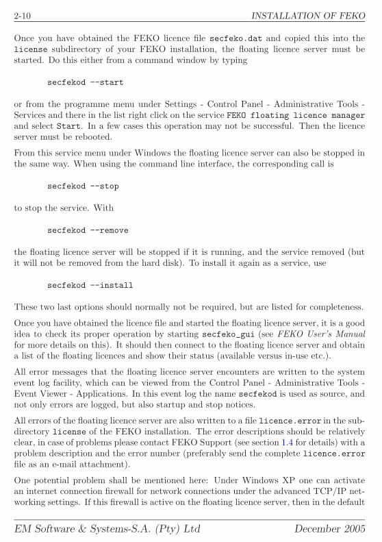
Once you have obtained the FEKO licence file secfeko.dat and copied this into thelicense subdirectory of your FEKO installation, the floating licence server must bestarted. Do this either from a command window by typing
secfekod --start
or from the programme menu under Settings - Control Panel - Administrative Tools -Services and there in the list right click on the service FEKO floating licence managerand select Start. In a few cases this operation may not be successful. Then the licenceserver must be rebooted.
From this service menu under Windows the floating licence server can also be stopped inthe same way. When using the command line interface, the corresponding call is
secfekod --stop
to stop the service. With
secfekod --remove
the floating licence server will be stopped if it is running, and the service removed (butit will not be removed from the hard disk). To install it again as a service, use
secfekod --install
These two last options should normally not be required, but are listed for completeness.
Once you have obtained the licence file and started the floating licence server, it is a goodidea to check its proper operation by starting secfeko_gui (see FEKO User’s Manualfor more details on this). It should then connect to the floating licence server and obtaina list of the floating licences and show their status (available versus in-use etc.).
All error messages that the floating licence server encounters are written to the systemevent log facility, which can be viewed from the Control Panel - Administrative Tools -Event Viewer - Applications. In this event log the name secfekod is used as source, andnot only errors are logged, but also startup and stop notices.
All errors of the floating licence server are also written to a file licence.error in the sub-directory license of the FEKO installation. The error descriptions should be relativelyclear, in case of problems please contact FEKO Support (see section 1.4 for details) with aproblem description and the error number (preferably send the complete licence.errorfile as an e-mail attachment).
One potential problem shall be mentioned here: Under Windows XP one can activatean internet connection firewall for network connections under the advanced TCP/IP net-working settings. If this firewall is active on the floating licence server, then in the default
EM Software & Systems-S.A. (Pty) Ltd December 2005
INSTALLATION OF FEKO 2-11
configuration, incoming connections to the chosen TCP port (see comment above, bydefault 11601) will be blocked and clients attempting to connect to the floating licenceserver will terminate with a suitable error message. In this case please configure thefirewall such that incoming connections on this TCP port are allowed from your domain(add a specific service secfekod to the firewall settings, see the Windows documentationon how to do this).
2.4.3 Floating licence server installation and maintenance (UNIX)
Under UNIX, perform a standard installation of FEKO on the machine that shall act asa floating licence server and on all the client machines where FEKO shall be used, seesection 2.3.
A request file will be created during the FEKO installation, and please send this requestfile of the server (and not the ones of the client machines) to EMSS. See section 2.2.5 fordetails.
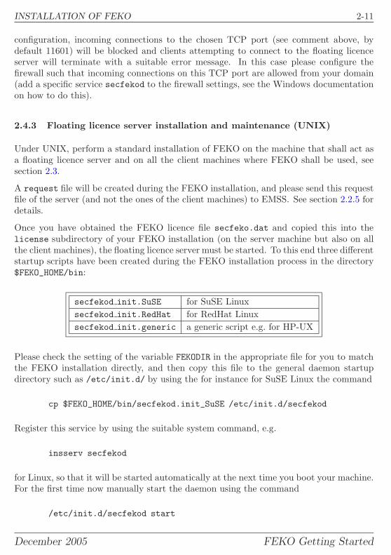
Once you have obtained the FEKO licence file secfeko.dat and copied this into thelicense subdirectory of your FEKO installation (on the server machine but also on allthe client machines), the floating licence server must be started. To this end three differentstartup scripts have been created during the FEKO installation process in the directory$FEKO_HOME/bin:
secfekod init.SuSE for SuSE Linuxsecfekod init.RedHat for RedHat Linuxsecfekod init.generic a generic script e.g. for HP-UX
Please check the setting of the variable FEKODIR in the appropriate file for you to matchthe FEKO installation directly, and then copy this file to the general daemon startupdirectory such as /etc/init.d/ by using the for instance for SuSE Linux the command
cp $FEKO_HOME/bin/secfekod.init_SuSE /etc/init.d/secfekod
Register this service by using the suitable system command, e.g.
insserv secfekod
for Linux, so that it will be started automatically at the next time you boot your machine.For the first time now manually start the daemon using the command
/etc/init.d/secfekod start
December 2005 FEKO Getting Started
2-12 INSTALLATION OF FEKO
This will start the floating licence server as a background process. This is the recom-mended way of operation, but root privileges will be required. Should this not be de-sired, one can also just start the FEKO floating licence server in an interactive mode(use $FEKO_HOME/bin/secfekod -i) or as daemon (use $FEKO_HOME/bin/secfekod -d)under any user account.
Once you have started the floating licence server, it is a good idea to check its properoperation by starting secfeko_gui (see FEKO User’s Manual for more details on this). Itshould then connect to the floating licence server and obtain a list of the floating licencesand show their status (available versus in-use etc.).
This utility secfeko_gui is not available yet for all UNIX platforms. If not available,then use the command
secfeko -p
to retrieve and display such licence usage information.
In case of any errors: In the interactive mode (see startup option -i mentioned above)error messages that the floating licence server encounters are written to the console tostderr.
When running secfekod as a daemon (default and recommended), then all error messagesare written to the system event log facility, typically this is the file /var/log/messages.All startup and stop notices are also logged there.
For the daemon mode, all errors of the floating licence server are also written to a filelicence.error in the sub-directory license of the FEKO installation. The error de-scriptions should be relatively clear. In case of problems please contact FEKO Support(see section 1.4 for details) with a problem description and the error number (preferablysend the complete licence.error file as an e-mail attachment).
2.5 Setup of remote launching
A remote launching facility is available in FEKO so that for instance sequential or paralleljobs on a workstation or parallel cluster can be launched from a local desktop PC.
It is suggested that new users first install FEKO locally and familiarise themselves withFEKO. Then this section can be skipped. One can later came back to setup the remotelaunching if this is desired.
For the remote launching in FEKO, there is no need for the file systems to be shared,all the file copy operations are performed automatically. Also the progress of the remoterun (including warning or error messages) can be monitored locally, similar to launchingthe job locally. This remote launching is also cross platform, one can for instance launch
EM Software & Systems-S.A. (Pty) Ltd December 2005
INSTALLATION OF FEKO 2-13
a remote job from a Windows PC on a Linux cluster or on an HP workstation, but alsofrom Linux to Linux, or even from a SUN workstation to a Windows PC etc.
The requirements and setup of this remote launching facility shall be described here:
• FEKO must be installed on both the local client and the remote host. Also validFEKO licences must be available on both computers. When using floating licences,two separate licences will be required, one for the client and one for the remote host.It is, however, possible to use a local GUI–only licence to launch a full FEKO jobelsewhere.
• The remote launching and file copy operations are based on the SSH protocol.Thus an SSH client must be installed on the local machine and an SSH servermust be running on the remote host. For UNIX / Linux machines this is typicallyreadily the case. If not, one implementation is OpenSSH which is available fromhttp://www.openssh.com.
For Windows clients different SSH implementations exist (e.g. CYGWIN or PUTTY).For Windows servers CYGWIN can be used (see http://cygwin.com)
• On the client the ssh and scp executables must be in the local PATH.
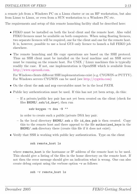
• Public key authentication must be used. If this has not yet been setup, do this:
– If a private/public key pair has not yet been created on the client (check forfiles $HOME/.ssh/id_dsa*), then run
ssh-keygen -t dsa -N ""
in order to create such a public/private DSA key pair.
– In the local directory $HOME/.ssh a file id_dsa.pub is then created. Copythis to the remote host and there append to the file authorized_keys in the$HOME/.ssh directory there (create this file if it does not exist).
• Verify that SSH is working with public key authentication. Type on the client
ssh remote_host ls
where remote_host is the hostname or IP address of the remote host to be used.This should give a listing of the files in the home directory on the remote host. Ifnot then the error message should give an indication what is wrong. One can alsocreate debug output using the verbose option -v as follows:
ssh -v remote_host ls
December 2005 FEKO Getting Started
2-14 INSTALLATION OF FEKO
• On the remote host the FEKO environment must be set properly. Verify this with
ssh remote_host prefeko
If the executable prefeko is not found, then the environment variables as defined in$FEKO_HOME/bin/initfeko are not available. When using for instance the BASHshell on the remote host, make sure to add a line
. /opt/feko/bin/initfeko
(note the dot followed by a space) to your .bashrc file (adding this to .bash_profileas for a normal FEKO installation will not work since SSH opens a non-interactiveshell only). Also note that the path /opt/feko/bin might be different for yourFEKO installation.
• On the remote host the utilities mkdir (to create directories) and rm (to delete files)must be available. For UNIX / Linux this is the case, when using a Windows serverthese can be installed as part of CYGWIN (see above).
After these initial setup steps, remote FEKO jobs on other computers can be launched.Please see the FEKO User’s Manual for further usage instructions, both from within theFEKO GUI and also from the command line.
Advanced users or system administrators might deviate from the setup procedure asdescribed above. For instance, if public key based SSH authentication cannot be usedbut something else is available (like the insecure rsh with rcp for the file copy operations),then the corresponding FEKO remote launching scripts can be customised. For Windowsthis is the batch file feko_remote.bat and for UNIX installations of FEKO this is the shellscript feko_parallel, both residing in the bin subdirectory of the FEKO installation.Please see the comments in these files. Note, however, that when updating FEKO anychanges made to these files will be overwritten, so make a backup copy and keep at a safeplace.
2.6 Adobe Reader installation
A PDF viewer is required to view and/or print the Getting Started Manual, the ExamplesGuide and the FEKO User’s Manual that are available on the FEKO CD in the docdirectory (and are installed in the doc subdirectory under the FEKO installation).
The Adobe Reader 7.0 can be downloaded from
http://www.adobe.com/products/acrobat/readstep.html
EM Software & Systems-S.A. (Pty) Ltd December 2005

RECTANGULAR HORN ANTENNA EXAMPLE 3-1
3 Getting started example 1: Rectangular Horn ex-ample
The first example makes use of an already set up and solved model of a horn antenna tofamiliarise the user with the FEKO program flow. The discussion assumes that this isread after the demo has been watched. If this is not the case, it is strongly recommendthat the demo be watched before working through this example. (The demo exampleis the short movie of the solution of a horn antenna that is shipped with the FEKOinstallation.) The demo can be found in the doc subdirectory of the FEKO installation.For Windows installations, this file is an .exe file, which can be executed directly. OnLinux installations, the demo is opened inside an .htm file.
3.1 Example overview
This example uses the same antenna as the demo example. The geometry is that of arectangular horn with a probe feed in a short waveguide section. ( Please refer to the textexample example_08 for a discussion of ways to feed a horn with a waveguide excitation. )The demo example shows the construction of the horn, the specification of the excitation,and the request of the near and far field patterns and basic display of the results. Thisexample concerns itself with the reinforcement of the program model and the use of thedifferent FEKO components. This example should take 30 minutes to work through.
The example is already set up and solved, and can be found in the examples\projects\horndirectory of the FEKO installation. It is expected that while working through this text,the steps are followed sequentially. As far as is possible, the example is designed suchthat steps are independent of order, but it is not always possible to achieve this. If anexplanation seems out of context, it might depend on a previous step.
3.2 Creation of the geometry in CADFEKO
The first step in every FEKO solution is to construct the geometry. The geometry iscreated by the component CADFEKO and stored in the *.cfx file. To start CADFEKOfrom the Windows Start menu, choose
Programs → FEKO → CADFEKOor open a console window and type cadfeko.
From the main menu in CADFEKO select File → Open and select the file horn.cfx inthe examples\projects\horn directory of the FEKO installation. The geometry of thehorn is now visible on the screen. The CADFEKO interface has a Windows look and feel,which should be familiar to most users.
December 2005 FEKO Getting Started
3-2 RECTANGULAR HORN ANTENNA EXAMPLE
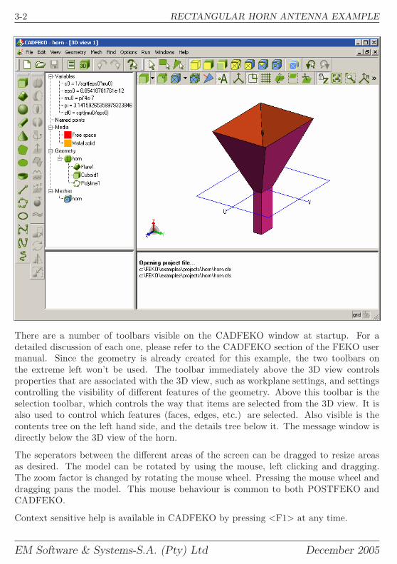
There are a number of toolbars visible on the CADFEKO window at startup. For adetailed discussion of each one, please refer to the CADFEKO section of the FEKO usermanual. Since the geometry is already created for this example, the two toolbars onthe extreme left won’t be used. The toolbar immediately above the 3D view controlsproperties that are associated with the 3D view, such as workplane settings, and settingscontrolling the visibility of different features of the geometry. Above this toolbar is theselection toolbar, which controls the way that items are selected from the 3D view. It isalso used to control which features (faces, edges, etc.) are selected. Also visible is thecontents tree on the left hand side, and the details tree below it. The message window isdirectly below the 3D view of the horn.
The seperators between the different areas of the screen can be dragged to resize areasas desired. The model can be rotated by using the mouse, left clicking and dragging.The zoom factor is changed by rotating the mouse wheel. Pressing the mouse wheel anddragging pans the model. This mouse behaviour is common to both POSTFEKO andCADFEKO.
Context sensitive help is available in CADFEKO by pressing <F1> at any time.
EM Software & Systems-S.A. (Pty) Ltd December 2005
RECTANGULAR HORN ANTENNA EXAMPLE 3-3
3.2.1 The contents tree
The contents tree is located to the left of the 3D view. It contains a history of the geometrycreation process as well as the resultant mesh information and any variables/named pointsthat were used during the creation process.
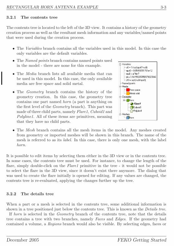
• The Variables branch contains all the variables used in this model. In this case theonly variables are the default variables.
• The Named points branch contains named points usedin the model - there are none for this example.
• The Media branch lists all available media that canbe used in this model. In this case, the only availablemedia are free space and solid metal.
• The Geometry branch contains the history of thegeometry creation. In this case, the geometry treecontains one part named horn (a part is anything onthe first level of the Geometry branch). This part wasmade of three child parts, namely Flare1, Cuboid1 andPolyline1. All of these items are primitives, meaningthat they have no child parts.
• The Mesh branch contains all the mesh items in the model. Any meshes createdfrom geometry or imported meshes will be shown in this branch. The name of themesh is referred to as its label. In this case, there is only one mesh, with the labelhorn.
It is possible to edit items by selecting them either in the 3D view or in the contents tree.In some cases, the contents tree must be used. For instance, to change the length of theflare, simply double-click on the Flare1 primitive in the tree - it would not be possibleto select the flare in the 3D view, since it doesn’t exist there anymore. The dialog thatwas used to create the flare initially is opened for editing. If any values are changed, thecontents tree is re-evaluated, applying the changes further up the tree.
3.2.2 The details tree
When a part or a mesh is selected in the contents tree, some additional information isshown in a tree positioned just below the contents tree. This is known as the Details tree.
If horn is selected in the Geometry branch of the contents tree, note that the detailstree contains a tree with two branches, namely Faces and Edges. If the geometry hadcontained a volume, a Regions branch would also be visible. By selecting edges, faces or
December 2005 FEKO Getting Started
3-4 RECTANGULAR HORN ANTENNA EXAMPLE
regions in this tree, local properties (like mesh size) can be set. Note that in this caseone of the edges is named feed.
If horn is selected in the Meshes branch of the contents tree, note that the details treecontains a branch called Labels. This tree contains all the subsets of the horn that canbe individually isolated during later processing. For instance, the tree contains the labelfeed. This means that there is a label horn.feed that can be used to uniquely identify thesegment that is used for the excitation.
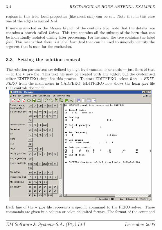
3.3 Setting the solution control
The solution parameters are defined by high level commands or cards — just lines of text— in the *.pre file. This text file may be created with any editor, but the customisededitor EDITFEKO simplifies this process. To start EDITFEKO, select Run → EDIT-FEKO from the main menu in CADFEKO. EDITFEKO now shows the horn.pre filethat controls the model.
Each line of the *.pre file represents a specific command to the FEKO solver. Thesecommands are given in a column or colon delimited format. The format of the command
EM Software & Systems-S.A. (Pty) Ltd December 2005

RECTANGULAR HORN ANTENNA EXAMPLE 3-5
does not need to be understood by the user to use the program. To modify a command,simply move the cursor to that line and press <F1>. A panel will open on the left side ofthe window. The panel is used to edit the command in a user friendly way. The commandname is given by the first two letters of each line. The commands used in this exampleare:
• ** This is not a command - it is a comment that can be inserted anywhere in thefile to describe the solution control.
• IN This command instructs the solver to retrieve the mesh information that wassaved by CADFEKO.
• SF This command tells the FEKO solver that all dimension related values shouldbe scaled to get them into meters. In this example, all dimensions are entered incentimeter, so the scale factor should be 0.01.
• EG This command seperates the the geometry related information (above the com-mand) and the control information (below the command.
• FR A number of different types of frequency solutions can be selected. This com-mand specifies the method that should be used, and any parameters associated withit. In this case, a single frequency calculation is requested.
• A1 Each excitation type in FEKO is designated with a command starting with anA. An A1 type excitation specifies the voltage over a specified segment. In this casethe segment with the label horn.feed is used, and a voltage of 1 is set.
• FE This command instructs the solver to calculate near field results. The requiredcoordinates for the calculation must be specified. A number of options, includingcoordinate system choice and field type choice, can be selected on the panel. In thiscase, a plane of near fields is requested in the opening of the horn. Both E and Hfields are calculated.
• FF This command is used to instruct the solver to calculate the radiated or far fieldpattern of the antenna. This must always be in spherical coordinates. In this casea full 3D pattern is requested.
• EN The last command is to let the solver know that the model is now complete.
The commands are executed sequentially. Certain commands result in a set of commandsbeing run in a loop. More information can be found in the user manual. Note that if nofield, current, coupling or other result is requested, FEKO will not solve the model, as nooutput is requested. The geometry can also be specified in terms of commands.
December 2005 FEKO Getting Started
3-6 RECTANGULAR HORN ANTENNA EXAMPLE
3.4 Obtaining a Solution
In this example, the solution is provided to save time. Ordinarily, once the model prepa-ration is complete (Geometry, mesh and control), the pre-processor PREFEKO is run.This program interprets the model and prepares it for solution by the FEKO solver. Thisinterpreted model is stored in a *.fek file. It is this file that is displayed by POSTFEKO.
Once the *.fek file is created, the FEKO solver can be run. If the FEKO solver is runfrom one of the GUI components, and one of the model input files has been changed,PREFEKO will be automatically launched before solving the model.
More comments on obtaining a solution can be found in the The program FEKO chapterof the User Manual.
3.5 Viewing the model and results
The POSTFEKO component of the FEKO suite is used for model validation (the processof checking that the simulated model represents the intended model) and result visuali-sation. To launch POSTFEKO, select Run → POSTFEKO from the menu bar in eitherCADFEKO or EDITFEKO.
POSTFEKO also makes use of the standard Windows look and feel, making it intuitive touse. Similarly to EDITFEKO, POSTFEKO has a control panel to the left of the 3D view.This panel is used to configure the current view. Many different types of results can bevisualised, meaning that many configuration options are needed. The options are groupedby basic functionality. The toolbar on the far left is used to select a group of optionsto set for the 3D visualisation window. The toolbar to the right of the view is used tocontrol the view camera. The toolbar above the view is used to add 2D result visualisationwindows to the current session or to launch one of the other FEKO components.
3.5.1 Model validation
Many models require significant computational resources to solve. It is therefore a goodidea to check that the model was correctly specified. POSTFEKO has features for thistask, collectively referred to as model validation tools. The two tools that will be used tovalidate this model are the Show excitation and the Display requested field points tools.
EM Software & Systems-S.A. (Pty) Ltd December 2005
RECTANGULAR HORN ANTENNA EXAMPLE 3-7
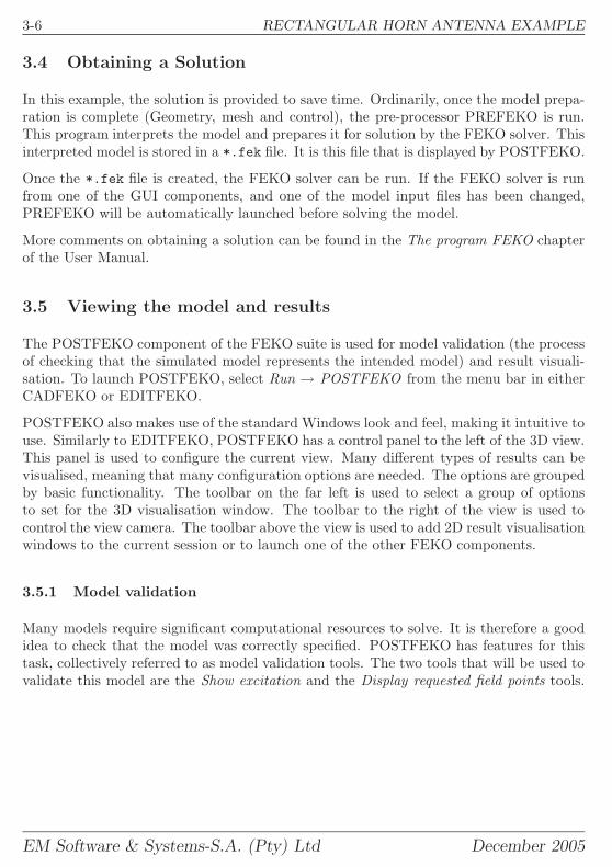
Select the Show excitation button on the left sidetoolbar. Rotate and zoom in the 3D view so thatfeed probe is visible. (Alternatively, the cutplanesoption on the left toolbar can be used to ’cut’through the mesh to see the feed probe.) Thefirst segment (connecting the waveguide wall tothe remainder of the probe) will have a red arrowon it indicating the location of the source.
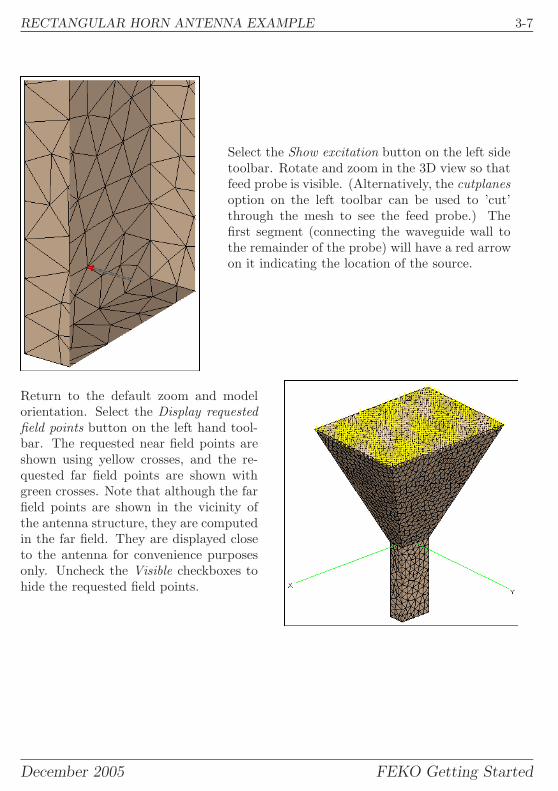
Return to the default zoom and modelorientation. Select the Display requestedfield points button on the left hand tool-bar. The requested near field points areshown using yellow crosses, and the re-quested far field points are shown withgreen crosses. Note that although the farfield points are shown in the vicinity ofthe antenna structure, they are computedin the far field. They are displayed closeto the antenna for convenience purposesonly. Uncheck the Visible checkboxes tohide the requested field points.
December 2005 FEKO Getting Started
3-8 RECTANGULAR HORN ANTENNA EXAMPLE
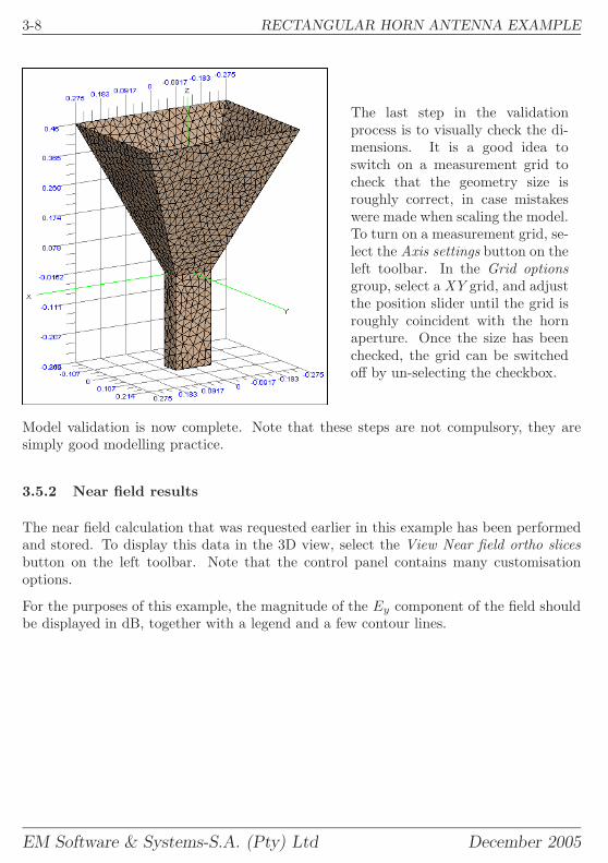
The last step in the validationprocess is to visually check the di-mensions. It is a good idea toswitch on a measurement grid tocheck that the geometry size isroughly correct, in case mistakeswere made when scaling the model.To turn on a measurement grid, se-lect the Axis settings button on theleft toolbar. In the Grid optionsgroup, select a XY grid, and adjustthe position slider until the grid isroughly coincident with the hornaperture. Once the size has beenchecked, the grid can be switchedoff by un-selecting the checkbox.
Model validation is now complete. Note that these steps are not compulsory, they aresimply good modelling practice.
3.5.2 Near field results
The near field calculation that was requested earlier in this example has been performedand stored. To display this data in the 3D view, select the View Near field ortho slicesbutton on the left toolbar. Note that the control panel contains many customisationoptions.
For the purposes of this example, the magnitude of the Ey component of the field shouldbe displayed in dB, together with a legend and a few contour lines.
EM Software & Systems-S.A. (Pty) Ltd December 2005
RECTANGULAR HORN ANTENNA EXAMPLE 3-9
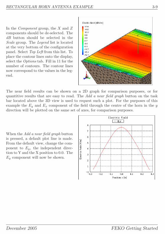
In the Component group, the X and Zcomponents should be de-selected. ThedB button should be selected in theScale group. The Legend list is locatedat the very bottom of the configurationpanel. Select Top Left from this list. Toplace the contour lines onto the display,select the Options tab. Fill in 11 for thenumber of contours. The contour linesnow correspond to the values in the leg-end.
The near field results can be shown on a 2D graph for comparison purposes, or forquantitive results that are easy to read. The Add a near field graph button on the taskbar located above the 3D view is used to request such a plot. For the purposes of thisexample the Ey and Ex component of the field through the centre of the horn in the ydirection will be plotted on the same set of axes, for comparison purposes.
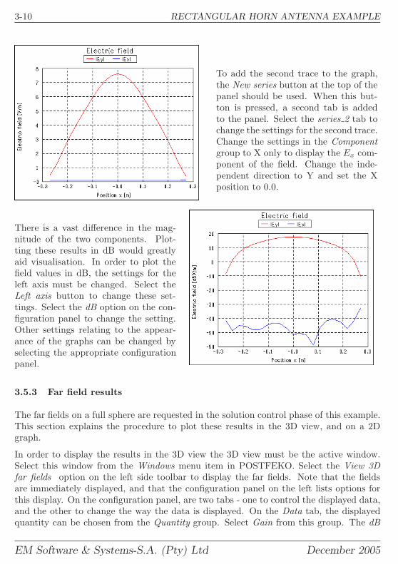
When the Add a near field graph buttonis pressed, a default plot line is made.From the default view, change the com-ponent to Ey, the independent direc-tion to Y and the X position to 0.0. TheEy component will now be shown.
December 2005 FEKO Getting Started
3-10 RECTANGULAR HORN ANTENNA EXAMPLE
To add the second trace to the graph,the New series button at the top of thepanel should be used. When this but-ton is pressed, a second tab is addedto the panel. Select the series 2 tab tochange the settings for the second trace.Change the settings in the Componentgroup to X only to display the Ex com-ponent of the field. Change the inde-pendent direction to Y and set the Xposition to 0.0.
There is a vast difference in the mag-nitude of the two components. Plot-ting these results in dB would greatlyaid visualisation. In order to plot thefield values in dB, the settings for theleft axis must be changed. Select theLeft axis button to change these set-tings. Select the dB option on the con-figuration panel to change the setting.Other settings relating to the appear-ance of the graphs can be changed byselecting the appropriate configurationpanel.
3.5.3 Far field results
The far fields on a full sphere are requested in the solution control phase of this example.This section explains the procedure to plot these results in the 3D view, and on a 2Dgraph.
In order to display the results in the 3D view the 3D view must be the active window.Select this window from the Windows menu item in POSTFEKO. Select the View 3Dfar fields option on the left side toolbar to display the far fields. Note that the fieldsare immediately displayed, and that the configuration panel on the left lists options forthis display. On the configuration panel, are two tabs - one to control the displayed data,and the other to change the way the data is displayed. On the Data tab, the displayedquantity can be chosen from the Quantity group. Select Gain from this group. The dB
EM Software & Systems-S.A. (Pty) Ltd December 2005
RECTANGULAR HORN ANTENNA EXAMPLE 3-11
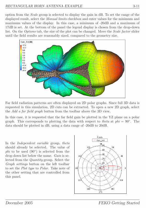
option from the Scale group is selected to display the gain in dB. To set the range of thedisplayed result, select the Manual limits checkbox and enter values for the minimum andmaximum values of the display. In this case, a minimum of -20dB and a maximum of17dB is set. At the bottom of the panel the legend display is chosen from the drop-downlist. On the Options tab, the size of the plot can be changed. Move the Scale factor slideruntil the field results are reasonably sized, compared to the geometry size.
Far field radiation patterns are often displayed on 2D polar graphs. Since full 3D data isrequested in this simulation, 2D cuts can be extracted. To open a new 2D graph, selectthe Add a far field graph button from the toolbar above the 3D view.
In this case, it is requested that the far field gain be plotted in the YZ plane on a polargraph. This corresponds to plotting the data with respect to theta at phi = 90◦. Thedata should be plotted in dB, using a data range of -20dB to 20dB.
In the Independent variable group, thetashould already be selected. The value ofphi to be used (90◦) is selected from thedrop down list below the name. Gain is se-lected from the Quantity group. Select theGraph settings button on the left toolbarto set the Plot type to Polar. Take note ofthe other setting that are controlled fromthis panel.
December 2005 FEKO Getting Started
3-12 RECTANGULAR HORN ANTENNA EXAMPLE
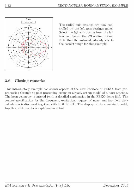
The radial axis settings are now con-trolled by the left axis settings panel.Select the left axis button from the lefttoolbar. Select the dB scaling option.Note that the autoscale already selectsthe correct range for this example.
3.6 Closing remarks
This introductory example has shown aspects of the user interface of FEKO, from pre-processing through to post processing, using an already set up model of a horn antenna.The horn geometry is entered (with a detailed explanation in the FEKO demo file). Thecontrol specification for the frequency, excitation, request of near- and far- field datacalculation is discussed together with EDITFEKO. The display of the simulated model,together with results is explained in detail.
EM Software & Systems-S.A. (Pty) Ltd December 2005

PATCH ANTENNA EXAMPLE 4-1
4 Getting started example 2: Patch antenna example
The second example introduces dielectric material into the model and sets local meshproperties. To illustrate the use of dielectric regions, a patch antenna on a substrate isused. Dielectric material modelling in FEKO is not restricted to planar antenna mod-elling. Dielectric regions of arbitrary shape and dielectric parameters can be used.
The example covers all phases of the modelling process. This necessarily means thatall phases must be executed sequentially. It is not possible to only work through onesubsection of this example. This example will take approximately 60 minutes to workthrough.
4.1 Example overview
The input impedance over frequency of a resonant patch antenna is investigated close toresonance. The patch (31.1807mm by 46.7480mm) is printed onto a finite sized substrate(50mm by 80mm) with a thickness of 2.87mm. The relative dielectric constant of thesubstrate is 2.2. The patch is fed with an SMA connector (pin diameter 1.3mm) located8.9mm from the centre of the long edge. The only observable of interest is the inputimpedance over the band 2.6 GHz to 3.1 GHz. Adaptive frequency sampling will be usedto reduce the number of frequency samples in the band.
4.2 Creation of the geometry in CADFEKO
The first step in every FEKO solution is to construct the geometry. The geometry iscreated by the component CADFEKO and stored in the *.cfx file. To start CADFEKOfrom the Windows Start menu, choose
Programs → FEKO → CADFEKOor open a console window and type cadfeko.
CADFEKO will start with a blank project. When enetring entities, all dimension relatedvalues will be entered in mm. For simplicity, the model will not use any variables orparameters.
The substrate is modelled using a cuboid. A polygon is drawn to represent the patchsurface. A wire element is drawn to model the feed pin. Properties for the substrate andlocal mesh settings are then set.
December 2005 FEKO Getting Started
4-2 PATCH ANTENNA EXAMPLE
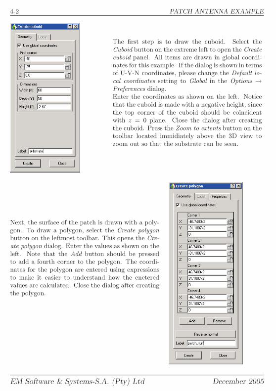
The first step is to draw the cuboid. Select theCuboid button on the extreme left to open the Createcuboid panel. All items are drawn in global coordi-nates for this example. If the dialog is shown in termsof U-V-N coordinates, please change the Default lo-cal coordinates setting to Global in the Options →Preferences dialog.Enter the coordinates as shown on the left. Noticethat the cuboid is made with a negative height, sincethe top corner of the cuboid should be coincidentwith z = 0 plane. Close the dialog after creatingthe cuboid. Press the Zoom to extents button on thetoolbar located immidiately above the 3D view tozoom out so that the substrate can be seen.
Next, the surface of the patch is drawn with a poly-gon. To draw a polygon, select the Create polygonbutton on the leftmost toolbar. This opens the Cre-ate polygon dialog. Enter the values as shown on theleft. Note that the Add button should be pressedto add a fourth corner to the polygon. The coordi-nates for the polygon are entered using expressionsto make it easier to understand how the eneteredvalues are calculated. Close the dialog after creatingthe polygon.
EM Software & Systems-S.A. (Pty) Ltd December 2005
PATCH ANTENNA EXAMPLE 4-3
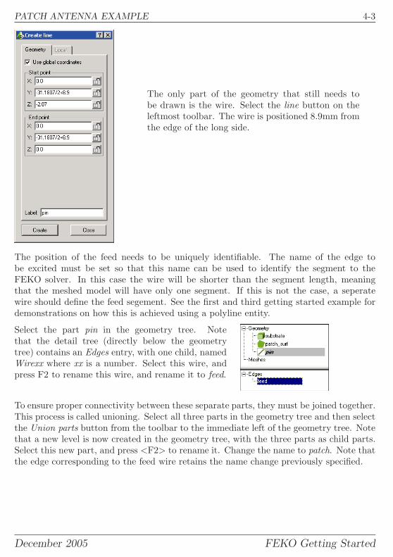
The only part of the geometry that still needs tobe drawn is the wire. Select the line button on theleftmost toolbar. The wire is positioned 8.9mm fromthe edge of the long side.
The position of the feed needs to be uniquely identifiable. The name of the edge tobe excited must be set so that this name can be used to identify the segment to theFEKO solver. In this case the wire will be shorter than the segment length, meaningthat the meshed model will have only one segment. If this is not the case, a seperatewire should define the feed segement. See the first and third getting started example fordemonstrations on how this is achieved using a polyline entity.
Select the part pin in the geometry tree. Notethat the detail tree (directly below the geometrytree) contains an Edges entry, with one child, namedWirexx where xx is a number. Select this wire, andpress F2 to rename this wire, and rename it to feed.
To ensure proper connectivity between these separate parts, they must be joined together.This process is called unioning. Select all three parts in the geometry tree and then selectthe Union parts button from the toolbar to the immediate left of the geometry tree. Notethat a new level is now created in the geometry tree, with the three parts as child parts.Select this new part, and press <F2> to rename it. Change the name to patch. Note thatthe edge corresponding to the feed wire retains the name change previously specified.
December 2005 FEKO Getting Started
4-4 PATCH ANTENNA EXAMPLE
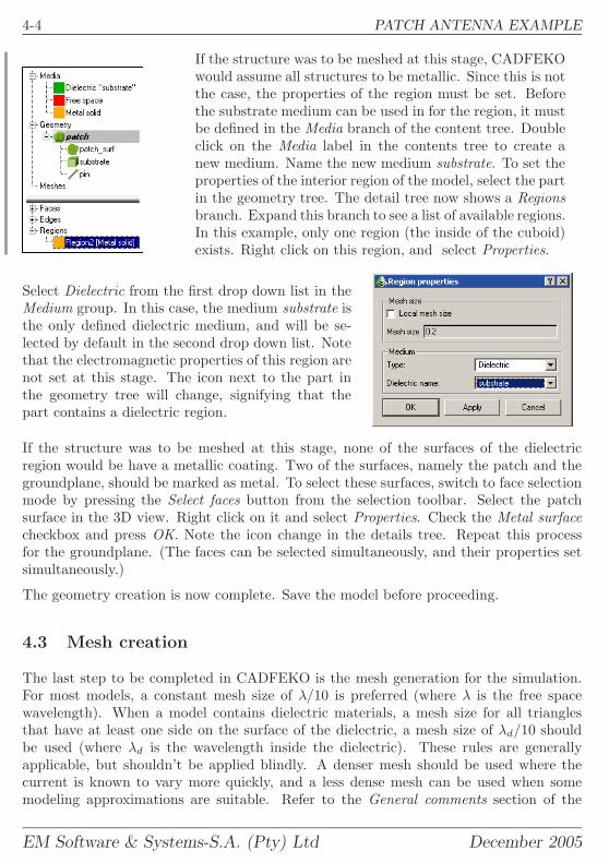
If the structure was to be meshed at this stage, CADFEKOwould assume all structures to be metallic. Since this is notthe case, the properties of the region must be set. Beforethe substrate medium can be used in for the region, it mustbe defined in the Media branch of the content tree. Doubleclick on the Media label in the contents tree to create anew medium. Name the new medium substrate. To set theproperties of the interior region of the model, select the partin the geometry tree. The detail tree now shows a Regionsbranch. Expand this branch to see a list of available regions.In this example, only one region (the inside of the cuboid)exists. Right click on this region, and select Properties.
Select Dielectric from the first drop down list in theMedium group. In this case, the medium substrate isthe only defined dielectric medium, and will be se-lected by default in the second drop down list. Notethat the electromagnetic properties of this region arenot set at this stage. The icon next to the part inthe geometry tree will change, signifying that thepart contains a dielectric region.
If the structure was to be meshed at this stage, none of the surfaces of the dielectricregion would be have a metallic coating. Two of the surfaces, namely the patch and thegroundplane, should be marked as metal. To select these surfaces, switch to face selectionmode by pressing the Select faces button from the selection toolbar. Select the patchsurface in the 3D view. Right click on it and select Properties. Check the Metal surfacecheckbox and press OK. Note the icon change in the details tree. Repeat this processfor the groundplane. (The faces can be selected simultaneously, and their properties setsimultaneously.)
The geometry creation is now complete. Save the model before proceeding.
4.3 Mesh creation
The last step to be completed in CADFEKO is the mesh generation for the simulation.For most models, a constant mesh size of λ/10 is preferred (where λ is the free spacewavelength). When a model contains dielectric materials, a mesh size for all trianglesthat have at least one side on the surface of the dielectric, a mesh size of λd/10 shouldbe used (where λd is the wavelength inside the dielectric). These rules are generallyapplicable, but shouldn’t be applied blindly. A denser mesh should be used where thecurrent is known to vary more quickly, and a less dense mesh can be used when somemodeling approximations are suitable. Refer to the General comments section of the
EM Software & Systems-S.A. (Pty) Ltd December 2005
PATCH ANTENNA EXAMPLE 4-5
FEKO user manual for more information regarding mesh size guidelines. In this example,the current is known to vary more quickly near to the long edges of the patch - makingthese a good candidate for finer meshing. A mesh density of λd/12 will be used as thegeneral mesh size, with a finer mesh along the two long edges of the patch, of λd/18. Bothof these mesh sizes are denser than the recommended guideline because of the thicknessof the substrate.
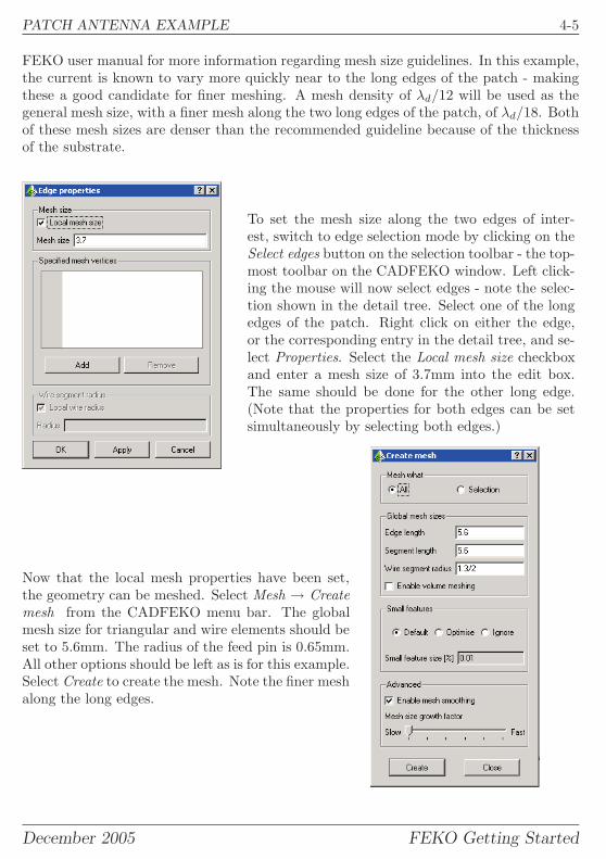
To set the mesh size along the two edges of inter-est, switch to edge selection mode by clicking on theSelect edges button on the selection toolbar - the top-most toolbar on the CADFEKO window. Left click-ing the mouse will now select edges - note the selec-tion shown in the detail tree. Select one of the longedges of the patch. Right click on either the edge,or the corresponding entry in the detail tree, and se-lect Properties. Select the Local mesh size checkboxand enter a mesh size of 3.7mm into the edit box.The same should be done for the other long edge.(Note that the properties for both edges can be setsimultaneously by selecting both edges.)
Now that the local mesh properties have been set,the geometry can be meshed. Select Mesh → Createmesh from the CADFEKO menu bar. The globalmesh size for triangular and wire elements should beset to 5.6mm. The radius of the feed pin is 0.65mm.All other options should be left as is for this example.Select Create to create the mesh. Note the finer meshalong the long edges.
December 2005 FEKO Getting Started
4-6 PATCH ANTENNA EXAMPLE
The mesh of the model is now complete. The model should be saved in CADFEKO atthis point.
4.4 Setting the solution control
The next step in the simulation procedure is to set the model parameters, such as fre-quency range, excitation, dielectric parameters and required observables. Parameters areset using the EDITFEKO user interface. In this example, adaptive (continuous) frequencysampling will be used, and the input impedance will be extracted.
EDITFEKO can be launched directly from the CADFEKO user interface. Select Run →EDITFEKO from the menu bar to launch the user interface.
As described in the preceding example, the model control is specified using a series ofsequential commands. The first two characters of each line specify the command, andthe parameters for the command are set in the configuration panel on the left. To openthe configuration panel for a specific command, place the cursor on the same line as thecommand, and press <F1>.
The first line of the standard control file starts with two asterisks. This means that thisline is not a command, rather a comment. Anything after the two asterisks is ignored byFEKO.
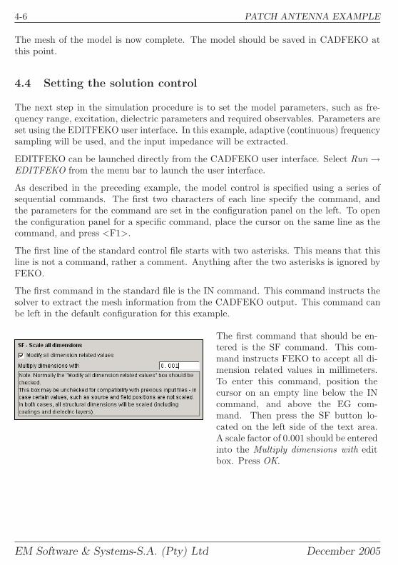
The first command in the standard file is the IN command. This command instructs thesolver to extract the mesh information from the CADFEKO output. This command canbe left in the default configuration for this example.
The first command that should be en-tered is the SF command. This com-mand instructs FEKO to accept all di-mension related values in millimeters.To enter this command, position thecursor on an empty line below the INcommand, and above the EG com-mand. Then press the SF button lo-cated on the left side of the text area.A scale factor of 0.001 should be enteredinto the Multiply dimensions with editbox. Press OK.
EM Software & Systems-S.A. (Pty) Ltd December 2005
PATCH ANTENNA EXAMPLE 4-7
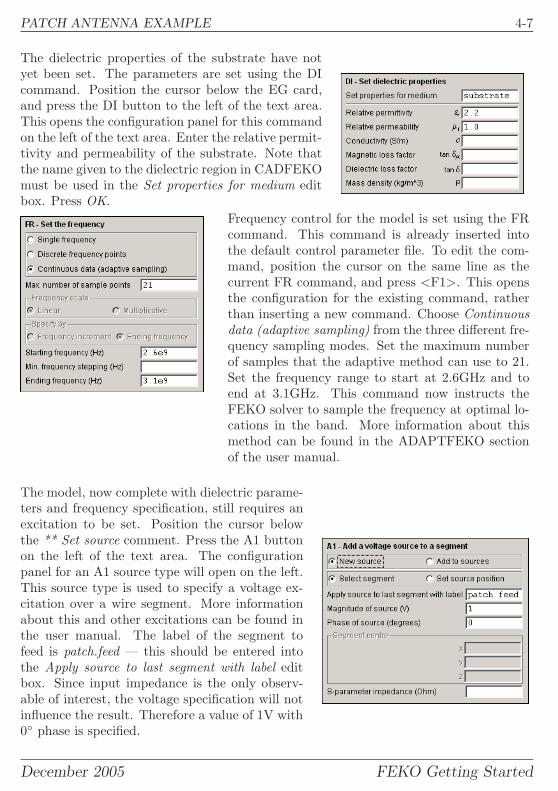
The dielectric properties of the substrate have notyet been set. The parameters are set using the DIcommand. Position the cursor below the EG card,and press the DI button to the left of the text area.This opens the configuration panel for this commandon the left of the text area. Enter the relative permit-tivity and permeability of the substrate. Note thatthe name given to the dielectric region in CADFEKOmust be used in the Set properties for medium editbox. Press OK.
Frequency control for the model is set using the FRcommand. This command is already inserted intothe default control parameter file. To edit the com-mand, position the cursor on the same line as thecurrent FR command, and press <F1>. This opensthe configuration for the existing command, ratherthan inserting a new command. Choose Continuousdata (adaptive sampling) from the three different fre-quency sampling modes. Set the maximum numberof samples that the adaptive method can use to 21.Set the frequency range to start at 2.6GHz and toend at 3.1GHz. This command now instructs theFEKO solver to sample the frequency at optimal lo-cations in the band. More information about thismethod can be found in the ADAPTFEKO sectionof the user manual.
The model, now complete with dielectric parame-ters and frequency specification, still requires anexcitation to be set. Position the cursor belowthe ** Set source comment. Press the A1 buttonon the left of the text area. The configurationpanel for an A1 source type will open on the left.This source type is used to specify a voltage ex-citation over a wire segment. More informationabout this and other excitations can be found inthe user manual. The label of the segment tofeed is patch.feed — this should be entered intothe Apply source to last segment with label editbox. Since input impedance is the only observ-able of interest, the voltage specification will notinfluence the result. Therefore a value of 1V with0◦ phase is specified.
December 2005 FEKO Getting Started
4-8 PATCH ANTENNA EXAMPLE
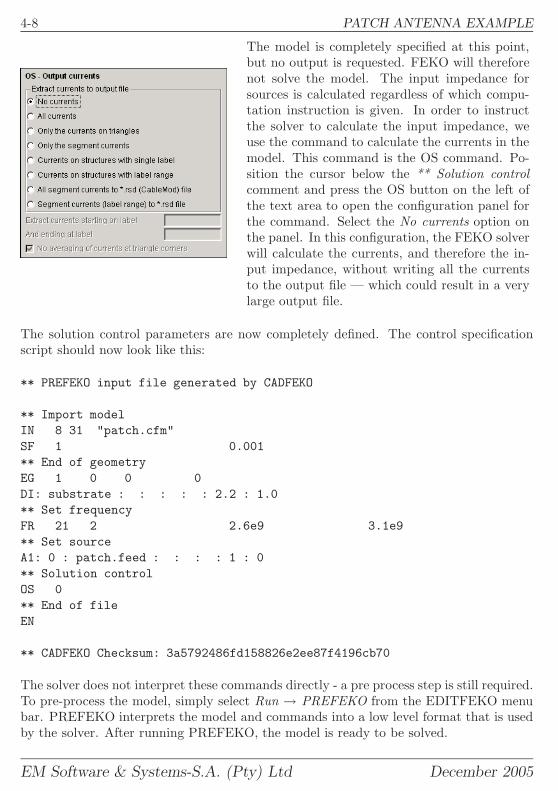
The model is completely specified at this point,but no output is requested. FEKO will thereforenot solve the model. The input impedance forsources is calculated regardless of which compu-tation instruction is given. In order to instructthe solver to calculate the input impedance, weuse the command to calculate the currents in themodel. This command is the OS command. Po-sition the cursor below the ** Solution controlcomment and press the OS button on the left ofthe text area to open the configuration panel forthe command. Select the No currents option onthe panel. In this configuration, the FEKO solverwill calculate the currents, and therefore the in-put impedance, without writing all the currentsto the output file — which could result in a verylarge output file.
The solution control parameters are now completely defined. The control specificationscript should now look like this:
** PREFEKO input file generated by CADFEKO
** Import modelIN 8 31 "patch.cfm"SF 1 0.001** End of geometryEG 1 0 0 0DI: substrate : : : : : 2.2 : 1.0** Set frequencyFR 21 2 2.6e9 3.1e9** Set sourceA1: 0 : patch.feed : : : : 1 : 0** Solution controlOS 0** End of fileEN
** CADFEKO Checksum: 3a5792486fd158826e2ee87f4196cb70
The solver does not interpret these commands directly - a pre process step is still required.To pre-process the model, simply select Run → PREFEKO from the EDITFEKO menubar. PREFEKO interprets the model and commands into a low level format that is usedby the solver. After running PREFEKO, the model is ready to be solved.
EM Software & Systems-S.A. (Pty) Ltd December 2005
PATCH ANTENNA EXAMPLE 4-9
4.5 Obtaining a solution
After completing the model preparation, the solver should be invoked to calculate therequested results. The solver can be invoked in a number of ways, from a commandwindow or from any one of the GUI components. In this example, the solver will beinvoked from EDITFEKO.
At this stage of the solution process, it is advisable to perform model validation, asdescribed in the first getting started example. In this case it is advisable to check thatthe metalisation of the patch and groundplane surfaces was correctly performed and thatthe scaling was correctly applied. To create the model from the script, select Run →PREFEKO from the EDITFEKO menu bar.
To invoke the solver from EDITFEKO select Run → FEKO from the menu bar. A windowwill open, giving step by step feedback as the simulation progresses. The solver will use6 frequency samples in the band. The simulation time should be between 70 and 100seconds per frequency, depending on the processor speed of the computer. Peak memoryutilisation should be of the order of 140MByte. The simulation time and peak memoryusage could be reduced significantly by exploiting the magnetic symmetry of this example.See the discussion on the use of symmetry in the FEKO user manual.
4.6 Visualisation of results
To launch POSTFEKO, select Run → POSTFEKO from the EDITFEKO menu bar.POSTFEKO will open, with the patch antenna in the 3D view. POSTFEKO is used forall post processing operations, including the plotting of input impedance versus frequencyas needed in this example.
A new graph that plots information relating to the source is started by pressing the Adda source data graph button on the 2D graphing toolbar. (This toolbar is located abovethe 3D view.)
A default graph of input impedance versus frequency is opened with the input impedanceat the first frequency sample point displayed. Continuous frequency sampling is used forthis example, meaning that the solver automatically chooses the frequency sample points.The sample points that were chosen can be seen in the list on the configuration panel.Below this list is a check box labelled Use continuous frequency. Select this checkboxto plot the results as calculated by the adaptive process. The magnitude of the inputimpedance over the entire frequency range will be shown. The sample points (the exactfrequencies at which a solution was obtained) are shown with markers. Select Real in thePart group to plot the real part of the input impedance rather than the magnitude. Toadd another trace (for the imaginary part of the impedance) select the New series buttonlocated on the toolbar at the top of the configuration panel. A second tab named series 2will be created on the configuration panel - select this tab.
December 2005 FEKO Getting Started

4-10 PATCH ANTENNA EXAMPLE
Turn on the continuous frequency sampling by checking the Use continuous frequencycheck box. The second trace will now be visible, showing the magnitude of the inputimpedance. Select Imag from the Part group to change this trace to display the imaginarypart of the input impedance.
The input impedance characteristics of the patch antenna are easily accessed from thisgraph. The graph can be customised using the settings panels available using the buttonson the toolbar to the very left of the window.
4.7 Closing remarks
A rectangular, pin fed, patch antenna on a finite sized dielectric substrate is simulated.The real and imaginary parts of the input impedance are plotted versus frequency in theband of interest.
The geometry is drawn entirely in CADFEKO. Three key steps are the setting of theregion properties for the substrate, setting the label of the feed segment and setting thelocal mesh properties along two of the edges.
The model control script is specified using the EDITFEKO user interface. The mesh isimported, a scale factor specified, substrate properties set, excitation specified and outputrequested.
The results are visualised using the POSTFEKO user interface.
EM Software & Systems-S.A. (Pty) Ltd December 2005
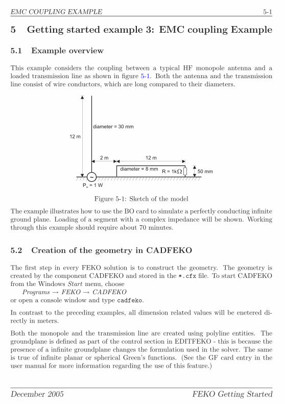
EMC COUPLING EXAMPLE 5-1
5 Getting started example 3: EMC coupling Example
5.1 Example overview
This example considers the coupling between a typical HF monopole antenna and aloaded transmission line as shown in figure 5-1. Both the antenna and the transmissionline consist of wire conductors, which are long compared to their diameters.
50 mm
12 m2 m
12 m
diameter = 8 mm
diameter = 30 mm
P = 1 Win
~
R = 1k�
Figure 5-1: Sketch of the model
The example illustrates how to use the BO card to simulate a perfectly conducting infiniteground plane. Loading of a segment with a complex impedance will be shown. Workingthrough this example should require about 70 minutes.
5.2 Creation of the geometry in CADFEKO
The first step in every FEKO solution is to construct the geometry. The geometry iscreated by the component CADFEKO and stored in the *.cfx file. To start CADFEKOfrom the Windows Start menu, choose
Programs → FEKO → CADFEKOor open a console window and type cadfeko.
In contrast to the preceding examples, all dimension related values will be enetered di-rectly in meters.
Both the monopole and the transmission line are created using polyline entities. Thegroundplane is defined as part of the control section in EDITFEKO - this is because thepresence of a infinite groundplane changes the formulation used in the solver. The sameis true of infinite planar or spherical Green’s functions. (See the GF card entry in theuser manual for more information regarding the use of this feature.)
December 2005 FEKO Getting Started
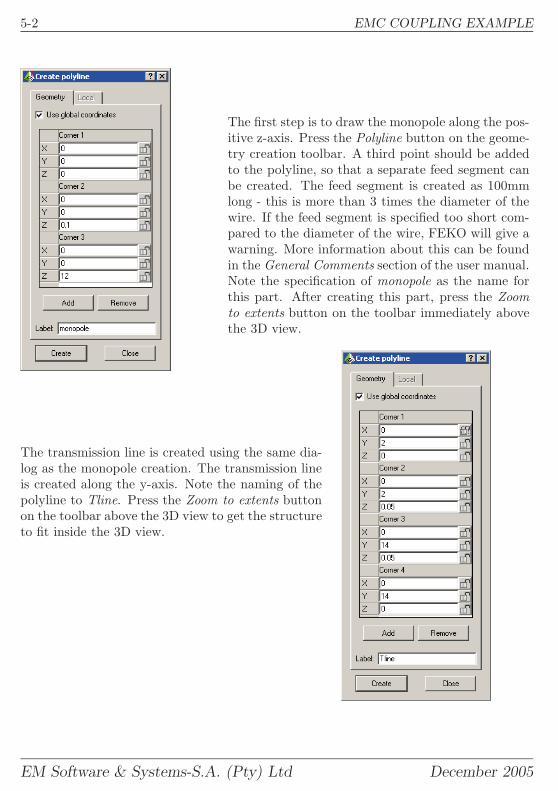
5-2 EMC COUPLING EXAMPLE
The first step is to draw the monopole along the pos-itive z-axis. Press the Polyline button on the geome-try creation toolbar. A third point should be addedto the polyline, so that a separate feed segment canbe created. The feed segment is created as 100mmlong - this is more than 3 times the diameter of thewire. If the feed segment is specified too short com-pared to the diameter of the wire, FEKO will give awarning. More information about this can be foundin the General Comments section of the user manual.Note the specification of monopole as the name forthis part. After creating this part, press the Zoomto extents button on the toolbar immediately abovethe 3D view.
The transmission line is created using the same dia-log as the monopole creation. The transmission lineis created along the y-axis. Note the naming of thepolyline to Tline. Press the Zoom to extents buttonon the toolbar above the 3D view to get the structureto fit inside the 3D view.
EM Software & Systems-S.A. (Pty) Ltd December 2005

EMC COUPLING EXAMPLE 5-3
The feed segment of the monopole should be re-named, so that the label of the element can be easilyidentified to the FEKO solver. Open the Edges treein the detail tree of the monopole. Select the edgecorresponding to the feed segment, and press <F2>to change the name to feed.The radius of the two structures (monopole andtransmission line are not the same. A global wire ra-dius cannot be used. Select both edges in the detailtree of the monopole. Right click and select Proper-ties. On this dialog, the wire radius can be set. Setthe radius to 0.015m.
The load segment of the transmission line should berenamed, so that the label of the element can be eas-ily identified to the FEKO solver. Open the Edgestree in the detail tree of the transmission line. Selectthe edge corresponding to the load segment (chang-ing the zoom may be required for this), and press<F2> to change the name to load.The global wire radius will be set at a later stageequal to that of the transmission line (4mm). Itis therefore not necessary to set the wire radius forthese edges at this stage.
The geometry of the problem is now completely defined. The next step is to create amesh for the structure. It is advisable to save the example at this point.
December 2005 FEKO Getting Started
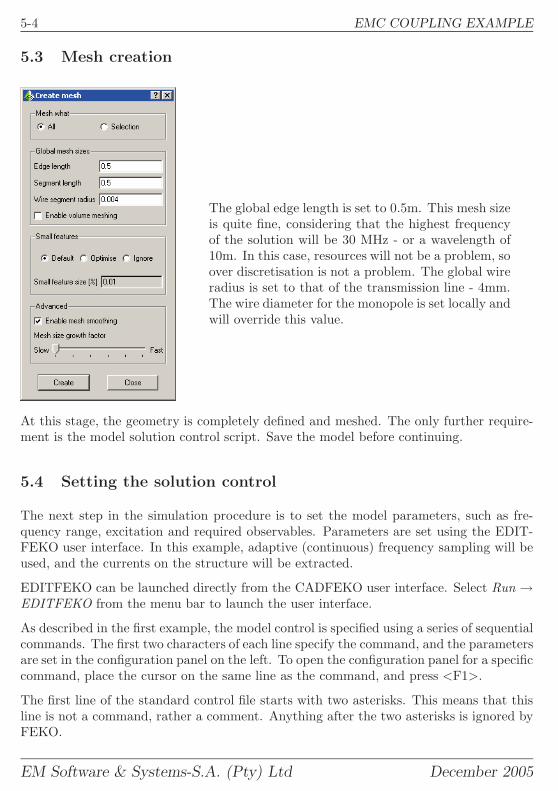
5-4 EMC COUPLING EXAMPLE
5.3 Mesh creation
The global edge length is set to 0.5m. This mesh sizeis quite fine, considering that the highest frequencyof the solution will be 30 MHz - or a wavelength of10m. In this case, resources will not be a problem, soover discretisation is not a problem. The global wireradius is set to that of the transmission line - 4mm.The wire diameter for the monopole is set locally andwill override this value.
At this stage, the geometry is completely defined and meshed. The only further require-ment is the model solution control script. Save the model before continuing.
5.4 Setting the solution control
The next step in the simulation procedure is to set the model parameters, such as fre-quency range, excitation and required observables. Parameters are set using the EDIT-FEKO user interface. In this example, adaptive (continuous) frequency sampling will beused, and the currents on the structure will be extracted.
EDITFEKO can be launched directly from the CADFEKO user interface. Select Run →EDITFEKO from the menu bar to launch the user interface.
As described in the first example, the model control is specified using a series of sequentialcommands. The first two characters of each line specify the command, and the parametersare set in the configuration panel on the left. To open the configuration panel for a specificcommand, place the cursor on the same line as the command, and press <F1>.
The first line of the standard control file starts with two asterisks. This means that thisline is not a command, rather a comment. Anything after the two asterisks is ignored byFEKO.
EM Software & Systems-S.A. (Pty) Ltd December 2005
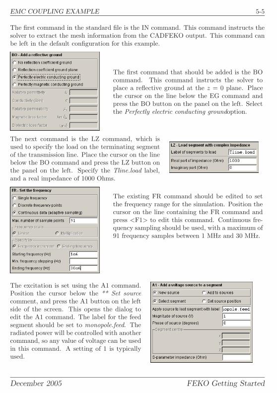
EMC COUPLING EXAMPLE 5-5
The first command in the standard file is the IN command. This command instructs thesolver to extract the mesh information from the CADFEKO output. This command canbe left in the default configuration for this example.
The first command that should be added is the BOcommand. This command instructs the solver toplace a reflective ground at the z = 0 plane. Placethe cursor on the line below the EG command andpress the BO button on the panel on the left. Selectthe Perfectly electric conducting groundoption.
The next command is the LZ command, which isused to specify the load on the terminating segmentof the transmission line. Place the cursor on the linebelow the BO command and press the LZ button onthe panel on the left. Specify the Tline.load label,and a real impedance of 1000 Ohms.
The existing FR command should be edited to setthe frequency range for the simulation. Position thecursor on the line containing the FR command andpress <F1> to edit this command. Continuous fre-quency sampling should be used, with a maximum of91 frequency samples between 1 MHz and 30 MHz.
The excitation is set using the A1 command.Position the cursor below the ** Set sourcecomment, and press the A1 button on the leftside of the screen. This opens the dialog toedit the A1 command. The label for the feedsegment should be set to monopole.feed. Theradiated power will be controlled with anothercommand, so any value of voltage can be usedin this command. A setting of 1 is typicallyused.
December 2005 FEKO Getting Started
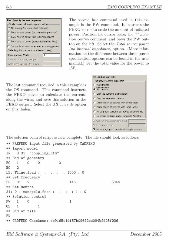
5-6 EMC COUPLING EXAMPLE
The second last command used in this ex-ample is the PW command. It instructs theFEKO solver to scale the amount of radiatedpower. Position the cursor below the ** Solu-tion control comment, and press the PW but-ton on the left. Select the Total source power(no internal impedance) option. (More infor-mation on the difference between these powerspecification options can be found in the usermanual.) Set the total value for the power to1W.
The last command required in this example isthe OS command. This command instructsthe FEKO solver to calculate the currentsalong the wires, and save this solution in theFEKO output. Select the All currents optionon this dialog.
The solution control script is now complete. The file should look as follows:** PREFEKO input file generated by CADFEKO** Import modelIN 8 31 "coupling.cfm"** End of geometryEG 1 0 0 0BO 2LZ: Tline.load : : : : : 1000 : 0** Set frequencyFR 91 2 1e6 30e6** Set sourceA1: 0 : monopole.feed : : : : 1 : 0** Solution controlPW 1 0 1OS 1 1** End of fileEN** CADFEKO Checksum: eb9165c1df57b096f2cd094bfd25f236
EM Software & Systems-S.A. (Pty) Ltd December 2005
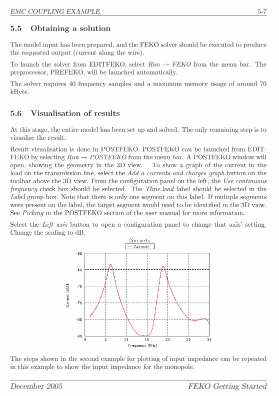
EMC COUPLING EXAMPLE 5-7
5.5 Obtaining a solution
The model input has been prepared, and the FEKO solver should be executed to producethe requested output (current along the wire).
To launch the solver from EDITFEKO, select Run → FEKO from the menu bar. Thepreprocessor, PREFEKO, will be launched automatically.
The solver requires 40 frequency samples and a maximum memory usage of around 70kByte.
5.6 Visualisation of results
At this stage, the entire model has been set up and solved. The only remaining step is tovisualise the result.
Result visualisation is done in POSTFEKO. POSTFEKO can be launched from EDIT-FEKO by selecting Run → POSTFEKO from the menu bar. A POSTFEKO window willopen, showing the geometry in the 3D view. To show a graph of the current in theload on the transmission line, select the Add a currents and charges graph button on thetoolbar above the 3D view. From the configuration panel on the left, the Use continuousfrequency check box should be selected. The Tline.load label should be selected in theLabel group box. Note that there is only one segment on this label. If multiple segmentswere present on the label, the target segment would need to be identified in the 3D view.See Picking in the POSTFEKO section of the user manual for more information.
Select the Left axis button to open a configuration panel to change that axis’ setting.Change the scaling to dB.
The steps shown in the second example for plotting of input impedance can be repeatedin this example to show the input impedance for the monopole.
December 2005 FEKO Getting Started
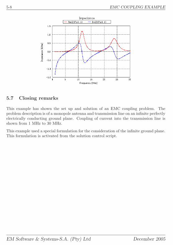
5-8 EMC COUPLING EXAMPLE
5.7 Closing remarks
This example has shown the set up and solution of an EMC coupling problem. Theproblem description is of a monopole antenna and transmission line on an infinite perfectlyelectrically conducting ground plane. Coupling of current into the transmission line isshown from 1 MHz to 30 MHz.
This example used a special formulation for the consideration of the infinite ground plane.This formulation is activated from the solution control script.
EM Software & Systems-S.A. (Pty) Ltd December 2005

MORE EXAMPLES 6-1
6 More examples
This ends the getting started examples for FEKO. During installation, a number ofexamples have been copied to the directory examples under the FEKO home directory.These are described in the Examples Guide.
You will need to run PREFEKO before you can view the geometry as no *.fek files areincluded in the installation. The FEKO solver will need to be run before any results canbe visualised, since no *.bof files or *.out files are included in the installation.
December 2005 FEKO Getting Started
Indexactivation
FEKO, UNIX version, 2-8FEKO, Windows version, 2-5
ADAPTFEKO, 4-9, 5-7Adobe Reader, 2-14AMD64, 2-5
CADFEKO, 1-2, 3-1, 4-1, 5-1contents tree, 3-3details tree, 3-3
card, 3-4, 4-6, 5-4A1 card, 3-5, 4-7, 5-5BO card, 5-5EG card, 3-5FE card, 3-5FF card, 3-5FR card, 3-5, 4-7, 5-5IN card, 3-5LZ card, 5-5OS card, 4-7, 5-6PW card, 5-5SF card, 3-5, 4-6
command, 3-4, 4-6, 5-4comment, 3-5contact us, 1-3Contents tree, 3-3continuous data, 4-9, 5-7coupling, 5-1cuboid, 4-1current
save, for visualisation, 4-7, 5-6
dB, 3-10demo, 3-1dielectric
parameters, 4-6dielectric material, 4-1dielectric name, 4-4
EDITFEKO, 1-2, 3-4, 4-6, 5-4EM64T, 2-2, 2-5EMC, 5-1environment variables
UNIX, 2-7Windows, 2-3
excitationlabel, 3-3, 4-3, 5-2name, 3-3, 4-3, 5-2setting of, 3-5, 4-7, 5-5showing of, 3-6
far fields, 3-7plotting of, 3-10requesting a calculation, 3-5
feed, see excitationsFEKO, 1-2FEKO LITE, 1-2, 2-5floating licences, 2-8
install, 2-9, 2-11frequency
setting of, 3-5, 4-7, 5-5
geometrycreation, 3-1, 4-1, 5-1
graph, 5-7multiple lines, 3-9, 4-9polar, 3-11
grid, 3-8ground PEC, 5-5
horn, 3-1HP, 2-5
impedance, 4-9, 5-7import
mesh, 3-5installation, 2-1
Adobe Reader, 2-14FEKO on Windows, 2-2, 2-3FEKO on workstations, 2-5floating licences, 2-8remote launching, 2-12
Itanium, 2-2, 2-5
Label, 3-3, 3-4licence, 1-2licence file
MS Windows, 2-5line, 4-2Linux, 2-5
I-1
load, 5-5label, 5-3name, 5-3
meshcreate, 4-4, 5-4edge refinement, 4-5
metallic face, 4-4model
control, 3-4, 4-6, 5-4model validation, 3-6monopole, 5-1
Named points, 3-3near fields, 3-7
display of, 3-8requesting a calculation, 3-5
operating systems, 1-2Opteron, 2-2OPTFEKO, 1-2
parallel installation, Windows, 2-3planar antenna, 4-1polygon, 4-2polyline, 5-1, 5-2port, see excitationsPOSTFEKO, 1-2, 3-6, 3-8, 3-10, 4-9, 5-7power, 5-5PREFEKO, 1-2, 3-6, 4-9, 5-6printing user’s manual, 2-14
radiation pattern, see far fieldsregion
properties, 4-4selection, 4-3
registration of FEKOUNIX, 2-8
remote launching, 2-12result
display, 3-8, 3-10, 4-9, 5-7
scale factor, 3-5, 4-6scratch files, 2-3SGI, 2-5SMA pin, 4-2solver
launching, 3-6, 4-9, 5-7
sources, see excitationssubstrate, 4-1SUN, 2-5system requirements
MS Windows, 2-2
temporary files, 2-3TIMEFEKO, 1-2
union, 4-3
Variables, 3-3
wire, 4-2radius, 5-3
workstation installation, 2-5
I-2