Embed Size (px)
Citation preview
Secure Web Appliance
Getting Started
copy 2013 CYAN Networks Software GmbH - ii -
Table of Contents1 Introduction 1
11 About CYAN Secure Web Appliance 112 About this Manual 1
121 Document Conventions 12 The Parts of the Appliance 23 The Appliance 34 Appliance Deployment 5
41 Out-of-line Deployment 542 In-line Deployment 543 DMZ Deployment 6
5 Proxy Modes 76 Installation of the Appliance 9
61 Connecting to the Network 9611 Connecting to the Appliance Port 9612 Connecting to the Management Port 9
62 Opening the Administration Interface 1063 Secure Web License 1264 User Support 1265 Changing the IP Address(es) 1366 Setting up the DNS 1467 Restricting Administration to the Management Port 14
7 Configuring the Proxy Service 1671 Service Proxy 1672 Activating the Anti-Virus Engine 1773 Testing your Installation 17
731 Setting up browser 187311 Internet Explorer 187312 Mozilla Firefox 197313 Google Chrome 207314 Opera 217315 Windows Domain 21
732 Testing access 238 Initial Configuration 26
81 Initial Authentication Setup 2682 Initial Profile Setup 2683 Initial Profile Assignment Setup 27
9 Updating Upgrading the Appliance 2910 Starting the Reporting System 31
101 Login to the Reporting System 31102 Setting up the Reporting Database 32103 Enabling the Log-Feeder 33
A Troubleshooting 34A1 Getting access to the command line 34
A11 Access via SSH 34A111 From UnixLinux 34A112 From Microsoft Windows 34
A12 Access using monitor and keyboard 36A2 Recover from an invalid IP address 36
B Contact data 37B1 How to contact our sales department 37B2 How to contact our support department 37
B21 Getting Support 37
copy 2013 CYAN Networks Software GmbH - iii -
List of Figures21 Appliance parts 231 Rear view of the model DS100 332 Rear view of the RS400 and RS6000 models 333 Rear view of the model DS1 (legacy model) 334 Rear view of the RS4 and RS6 models (legacy model) 335 Rear view of the RS8 model (legacy model) 336 Front view of the Appliance 441 Out-of-line deployment 542 In-line deployment 543 DMZ deployment 661 Welcome screen 1062 First login 1063 First login csupport account 1164 EULA 1165 Secure Web License 1266 Disabling the support user 1367 Network interfaces 1368 DNS Setup 1469 Bind management on management interface 1471 Services menu 1672 Service Proxy 1673 Anti Virus Engine 1774 Apply button 1775 Proxy setup - Internet Explorer 1876 Proxy setup - Mozilla Firefox 1977 Proxy setup - Google Chrome 2078 Proxy setup - Opera 2179 Adding a new GPO 22710 Setting the proxy IP address 22711 Configuring the GPO 23712 Category blocking page 24713 AV blocking of eicarcom download 2481 IP Instance default configuration 2682 Profile default configuration 2683 Default profile used 2784 Example IP List instance 2785 Example IP profile assignments 2891 Firmware upgrade screen 2992 Upgrade Service screen - upgrade 2993 Upgrade Service screen - upgrade 29101 Welcome screen 31102 Setup the reporting database 32103 Upgrade of the reporting database 33104 Log feeder 33A1 PuTTY window 35A2 Console main menu 35A3 Network interfaces 36B1 Version information of the Secure Web 37B2 Version information of the Reporting System 37B3 Support Package 38
copy 2013 CYAN Networks Software GmbH - iv -
List of Tables51 Proxy mode implications 7
copy 2013 CYAN Networks Software GmbH - 1 -
1 Introduction
11 About CYAN Secure Web Appliance
The all-in-one appliance hardware solution developed by CYAN Networks is an optimalcustomized platform that makes the deployment of Secure Web very easy The Applianceincludes a complete pre-installed Secure Web as well as a Web Admin Interface used for theconfiguration of the entire machine The product can easily be integrated into the already existinginfrastructures The configuration and other operating tasks are done with your favorite webbrowser thus no knowledge about the integrated operating system is required
12 About this Manual
This manual explains basic concepts and the first steps for installing and configuring of the CYANAppliance solution The reader is expected to have basic computer network knowledge and befamiliar with the usage of SSH (PuTTY) for troubleshooting There is no knowledge of the SecureWeb platform necessary prior reading this document
This manual is to be used with a CYAN Appliance with Secure Web version 21 and above
For additional documentation please see our document repository on httpwwwcyan-networkscomdocumentation
121 Document Conventions
Indicates a potentially risky situation leaving the appliance in an unusable state
Indicates a potentially risky situation causing misfunction of the solutions
Indicates information that is substantial for successfully configuring and using theproduct
Provides helpful information for the process of configuring and using the product
Provides additional information about typical scenarios and best practices
copy 2013 CYAN Networks Software GmbH - 2 -
2 The Parts of the Appliance
The DS100 Appliance package contains the following parts
bull the desktop machine
bull a power cord
bull a power supply
bull a 1 GB SD memory card
The RS 400 6000 8000 and 8000-X Appliance packages contain the following parts
bull the rack mountable machine
bull a power cord
bull an SD memory card
Figure 21 Appliance parts
copy 2013 CYAN Networks Software GmbH - 3 -
3 The ApplianceThe following pictures show the rear view of the Appliance models and the numbering of theethernet ports
Figure 31 Rear view of the model DS100
Figure 32 Rear view of the RS400 and RS6000 models
Figure 33 Rear view of the model DS1 (legacy model)
Figure 34 Rear view of the RS4 and RS6 models (legacy model)
Figure 35 Rear view of the RS8 model (legacy model)
Each ethernet port has a specific usage
bull Port I0 is the proxy interface that takes up the client requests
bull Port I1 is used for bridging and in dual-homed deployments for the outgoing proxy requests
bull Port MG is defined as the management port
The Appliance
copy 2013 CYAN Networks Software GmbH - 4 -
bull Port HA is used to connect two CYAN Appliances for operating in high-availability mode
Ports MG and HA are not available on DS100 model but MG port can be configured on it insteadof one of the Ix ports
The representation of the ethernet ports on the embedded Linux operating system isfollowing I0 = eth0 I1 = eth1 MG = eth2 HA = eth3
The following picture shows the front view of an Appliance in factory mode
Figure 36 Front view of the Appliance
The front LCD of the Appliance shows the current network status of the machine
The display switches between two screens and shows the following information
bull BR the IP address assigned to the ethernet bridge (ports I0 and I1 not available on DS100model)
bull MG the IP address assigned to the management port (MG not available on DS100 model)
bull HA the current status of the machine in a high-availability environment A machine that is nota member of a cluster will show ldquopassive+workerrdquo
bull SV the IP address assigned as the Service IP
In default configuration the Appliance tries to retrieve an IP address via DHCP on the bridged (BR)interface If unsuccessful ltundefinedgt will be displayed in the BR line The management interfaceMG is pre-configured with a static IP of 19216811 and a network mask of 2552552550
Immediately after connecting one of the bridged ports (ports 1 or 2) to the network thebridge needs to learn about the network It can take up to one minute until the DHCPrequest is issued and an IP address is assigned
The four control buttons right next to the power button are deactivated in the currentversion of the appliance
copy 2013 CYAN Networks Software GmbH - 5 -
4 Appliance DeploymentThere are numerous ways in which the Appliance can be deployed in the network the basicconcepts being out-of-line in-line and in the demilitarized zone (DMZ)
41 Out-of-line Deployment
The following diagram illustrates the out-of-line deployment
Figure 41 Out-of-line deployment
In the out-of-line deployment the Appliance resides on the same physical network as the clientsThe clients must not necessarily use the Appliance for their Internet access However in order toensure security the firewall must be configured to disallow all direct traffic from the client to theInternet To utilize the Appliance either all clients are explicitly configured to use the Appliance ora rule on the firewall utilizes the Appliance into transparent mode applying port forwarding rules
To deploy the Appliance out-of-line one of the ethernet ports I0 or I1 must be connected to theswitch that builds your local network
42 In-line Deployment
The following diagram illustrates the in-line deployment
Figure 42 In-line deployment
Appliance Deployment
copy 2013 CYAN Networks Software GmbH - 6 -
In the in-line deployment the network will be physically split into two segments the segment whereall the clients reside and the segment that connects the Appliance with the firewall gateway
To deploy the Appliance in-line connect the ethernet port I0 of the Appliance to the switch thatbuilds your local network Your firewall gateway must be disconnected from this switch anddirectly connected with a cable to the ethernet port I1
In case you connect the DS100 Appliance with a direct cable to your firewall gatewayyou need to use a cross-over network cable The other models have 1 GB interfaces andthey can swap the lines in the cable automatically
43 DMZ Deployment
The following diagram illustrates the deployment in a DMZ
Figure 43 DMZ deployment
In the DMZ deployment the Appliance resides in part of the network that is protected by thefirewall from both the extranet and the intranet In the case that a DMZ is established alreadythis is the preferred mode especially if authentication shall be used and the authentication serveris on this network
To deploy the Appliance in the DMZ one of the ethernet ports I0 or I1 must be connected to theswitch that builds your demilitarized zone
If your Appliance model is not DS100 in any of the main three basic modes the managementof the machine can be restricted to a separated management network In order to secure themanagement access connect the management port to the management network and follow thesteps described in Section 67 ldquoRestricting Administration to the Management Portrdquo
copy 2013 CYAN Networks Software GmbH - 7 -
5 Proxy ModesProxy Mode refers to the way how clients ldquoseerdquo the Appliance One can differentiate betweentwo main modes non-transparent and transparent mode
Non-transparent (classic proxy) mode means that the clientrsquos application (eg your web browser)must be aware of the existence of the Appliance ie the client must be explicitly configured touse the Appliance in order to establish connections to the Internet
On the other hand in transparent mode the clientrsquos application does not know about theexistence of the Appliance Generally all traffic on TCP port 80 (HTTP) is redirected by a networkselement (router firewall the CYAN Appliance) to the Appliance ie the Appliance is ldquoinjectedrdquotransparently into the network traffic
Using each of these two modes has different consequences
bull non-transparent mode as described above each clientrsquos application needs to be configuredto use the Appliance which implies some additional administrative effort Furthermore in orderto be able to enforce the use of this security and policy gateway another network element(router firewall) must ensure by blocking that no direct traffic from a client passes to the InternetThis is a typical configuration option suitable for most of the deployments
bull transparent mode this mode requires the Appliance to be either deployed as an ethernetbridge or to configure port forwarding rules on your router or firewall device Please refer to thedocumentation of your router or firewall to find out about the necessary configuration stepsYou will most probably want to redirect all traffic that ldquogoes tordquo the TCP destination port 80which is the common port for HTTP servers However you may also want to redirect the ports3126 and 8080 which are commonly used by proxy servers This way you shall prevent theuse of external (possibly anonymous) proxies In this mode you can the user authentication bebased just on IP addresses
bull mix of both modes it is possible to combine both approaches If a transparent mode is usedit is still possible to use the non-transparent mode approach for some clients to because theport of the Appliance has still assigned an IP address to which can be requests send
In transparent mode the Appliance cannot support authentication based on the userIt also cannot support protocols that are bypassing the proxy like native ICQ andequivalent
Be careful when creating the redirect rule on your network device Make sure that thetraffic from the Appliance itself do not get redirected too otherwise it will start to loopbetween the firewall and the Appliance resulting in a failure of one or both devices
The following diagram gives an overview of the proxy modes in the deployments and theconsequences involved
Deployment Non-Transparentmode
Transparent mode Notes
Out-of-line ok Firewall Port forwarding by thefirewall required Non-trivial rules
In-line ok ok Single point of failureNot supported HA
Proxy Modes
copy 2013 CYAN Networks Software GmbH - 8 -
Deployment Non-Transparentmode
Transparent mode Notes
DMZ ok Firewall Port forwarding by thefirewall required
Table 51 Proxy mode implications
copy 2013 CYAN Networks Software GmbH - 9 -
6 Installation of the ApplianceAll administrative tasks can be carried out by using your favourite web browser In order to getthe access to the Web Admin Interface an IP address of your local network which is accessibleby your client PC must be assigned to the Appliance
In case of the factory settings the appliance will retrieve a dynamic IP address via DHCP You canfind the IP address on the front panel display (as seen in Figure 36 ldquoFront view of the Appliancerdquo)
In case you will not get any IP address assigned by DHCP you may connect your client PCto the management interface where a dedicated IP address is assigned (more in Section 612ldquoConnecting to the Management Portrdquo)
Once you have logged into the Web Admin Interface you will find the Appliances menu in theleft sidebar This menu provides all the options and actions for Appliances (more in Section 62ldquoOpening the Administration Interfacerdquo)
61 Connecting to the Network
The Appliance has four network ports The first time you setup the Appliance you will mostprobably choose to connect the proxy port I0 to your local network
In case you have a separated management network we recommend to use the managementport MG
Make sure that your company firewall allows the access to the Internet for the ApplianceThe ports that need to be granted are
Port Protocol Name
53 TCP UDP DNS
80 TCP HTTP
443 TCP HTTPS
611 Connecting to the Appliance Port
By default the Web Admin Interface is available on all Appliance ports (I0 I1) as well as on themanagement port (MG)
After connecting the port I0 to your local network the Appliance will try to retrieve a dynamic IPaddress using DHCP The ports I0 and I1 are bridged (BR) During the IP address retrieval theLCD will show BR ltundefinedgt After the IP address has been successfully retrived the displaywill change and the address will be shown accordingly
If you do not have a DHCP server on your network you may continue with Section 612ldquoConnecting to the Management Portrdquo and configure the IP address for the proxy portsmanually
612 Connecting to the Management Port
On the management interface port of the Appliance (MG) a static IP address is assigned Thefactory default is 19216811 with a netmask of 2552552550 In order to connect to thisIP address you will have to setup your client PC with an IP address and network mask for thisnetwork range (for example 192168122552552550) and physically attach your clientPC to this network port
Installation of the Appliance
copy 2013 CYAN Networks Software GmbH - 10 -
Users of the legacy Appliance model DS1 will have to apply a cross-over cable in casethat the client PC is attached directly to the management network port without anynetwork switch in between
62 Opening the Administration Interface
Point your browser to the address assigned via DHCP or the management IP (19216811) asthe case may be
httpsappliance-ip9992 (for example https192168119992)
The welcome screen allows you to either access the Web Admin Interface of the Secure Webor the Reporting System
Figure 61 Welcome screen
Click on Login next to CYAN Secure Web to navigate to the Web Admin Interface
When connecting for the first time to the Web Admin Interface you will be prompted to set up theadministrative account In this case enter a Username and a Password of your choice
Figure 62 First login
This user account will be the first administrator account put into the Super Administrator groupand is the only account allowed to create other administrative accounts
Installation of the Appliance
copy 2013 CYAN Networks Software GmbH - 11 -
It is extremely important not to forget the Super Administrator password While forAdministrator accounts can be the password changed by the Super Administrator atany time there is no quick and easy password recovery procedure for the SuperAdministrator account itself If this password is lost it is necessary to connect a CR-Rom drive over USB boot up a Linux distribution mount the file system and set a newpassword or alternatively send the whole Appliance back to Cyan Networks for repair
On Secure Web Appliances an additional console account csupport will be enabled with the samepassword The Appliance can be accessed via SSH protocol using this account (for example formaintenance purposes) For more information see Section A11 ldquoAccess via SSHrdquo
Figure 63 First login csupport account
Please read and acknowledge the End User License Agreement (EULA) that is shown after thefirst login Buttons to acknowledge the EULA are at the end of the document
Figure 64 EULA
Installation of the Appliance
copy 2013 CYAN Networks Software GmbH - 12 -
63 Secure Web License
Secure Web requires a valid license to operate In case you have not received your licenseinformation and would like to evaluate Secure Web please browse to the location
httpwwwcyan-networkscomregistration
and follow the instructions on the screen After a successful completion of the registration a keyfile that includes the evaluation license will be sent to your email address
In order to activate Secure Web with a valid license got to menu ServicesAdminLicense andupload the key file that is attached to the email you received after clicking the Secure Webbutton
In case you received a ZIP archive with your license do not uncompress it Thearchive contains your Secure Web license and any additional license that you may havepurchased and must be uploaded to Secure Web without uncompressing it on your own
Figure 65 Secure Web License
Immediately after uploading the Secure Web license the Appliance will start updating the URLdatabase The amount of downloaded data is about 100 MB so this can take several minutesdepending on the speed of your Internet connection
64 User Support
The Appliance machines come with a pre-configured user named csupport The primary purposeof this user is to provide access to the machine for the CYAN Networks support team The supportuser however can also be used by yourself to get access to the machine for troubleshooting
For the support user we installed the public key of the CYAN Networks support team It is thereforenot necessary to provide us with the password of the machine The authentication is instead doneby using publicprivate-key authentication
The support user is enabled by default and set to the password of the first administrative useraccount that has been created on the first login To disable the user got to menu AppliancesMaintenanceAppliance Accounts
Installation of the Appliance
copy 2013 CYAN Networks Software GmbH - 13 -
Figure 66 Disabling the support user
In a typical customer environment the proxy machine is located somewhere within the network orin the DMZ in any case behind a firewall In case you would like to provide the CYAN Networkssupport team with access to your machine please take care of a proper mapping of the connectionfor SSH from the public Internet to the Appliance machine
Due to security reasons the support user is disabled in the factory defaults but enabledduring the first login
We recommend that you leave the support user enabled prior to changing any networksettings leaving you with a possibility to recover an access to the machine without havingto reset it to the factory defaults
65 Changing the IP Address(es)
In order to change the IP address of your Appliance navigate to the menu ApplianceNetworkInterfaces
Figure 67 Network interfaces
After saving the changes the appliance will immediately reconfigure itself and apply the newIP configuration It takes the BR interface approximately 30 secondsto learn the network layoutThen you will have to reconnect to the Web Admin Interface on the new IP address
In case you setup a static IP address do not forget to adjust the DNS settings accordingly(see Section 66 ldquoSetting up the DNSrdquo)
Installation of the Appliance
copy 2013 CYAN Networks Software GmbH - 14 -
After changing the IP address the machine might be inaccessible by your client PC If youhave made a mistake please refer to Section A2 ldquoRecover from an invalid IP addressrdquoin order to manually reset the IP configuration
66 Setting up the DNS
For static network configurations you may specify up to three domain name servers in the menuAppliancesNetworkDNS In DHCP environments DNS servers are usually set up automatically
Figure 68 DNS Setup
67 Restricting Administration to the Management Port
The factory default allows the access to the Web Admin Interface on the bridge ports as well ason the management port In order to restrict the access only to the management port
1 Open the menu AppliancesNetworkFirewall
2 Disable the flag Allow management from IF0IF1 This will deny any access to the WebAdmin Interface that arrives on one of the bridged ports
Figure 69 Bind management on management interface
Installation of the Appliance
copy 2013 CYAN Networks Software GmbH - 15 -
The management interface does not support a gateway setting Access is enabled solelyfrom the management network segment
Make sure that you are connected via the management port of the Appliance Afterdisabling management on the proxy ports (I0 and I1) you will no longer have access tothe Web Admin Interface via this ports
copy 2013 CYAN Networks Software GmbH - 16 -
7 Configuring the Proxy ServiceCYAN Secure Web consists of a number of services that build the proxy web filtering andweb security product (Secure Web Proxy) All services and corresponding components can beconfigured via the Services menu found on the left
Figure 71 Services menu
71 Service Proxy
In most situations the Secure Web Proxy has no direct access to the Internet At least a companyfirewall is located between the proxy system and Internet access Sometimes an additionalupstream proxy needs to be used for an access
From the Secure Web Proxy access to the following resources is required for operationalpurposes Please make sure that access to these resources is allowed on any upstream firewallor proxy system
bull servicecyan-networkscom - TCP port 80 (HTTP) TCP port 443 (HTTPS)
bull appliancecyan-networkscom - TCP port 80 (HTTP)
bull debcyan-networkscom - TCP port 80 (HTTP)
In some situations the Secure Web Proxy has no direct access to the Internet and an upstreamproxy is needed for requests to CYAN update services In that case the parameters found in themenu ServicesAdminService Proxy need to be configured accordingly
Figure 72 Service Proxy
Configuring the Proxy Service
copy 2013 CYAN Networks Software GmbH - 17 -
Enable the use of an upstream proxy and specify the host and the port information in the dialogabove If the upstream proxy requires an authenticated users in order to be allowed to accessthe Internet this credentials have to be added here too
Only Basic Authentication is supported for upstream proxy access If unsure please askyour upstream proxy administrator for details on how to authenticate on the system
72 Activating the Anti-Virus Engine
The Appliance comes pre-installed with the Clam AV engine To enable virus scanning navigateto the menu ServicesProxy SettingsAnti Virus and enable the scan engine Please make surethat the selected Virus engine is set to External Scanner as shown in the screenshot below
Figure 73 Anti Virus Engine
In order for you to evaluate the ESET anti virus engine please send an e-mail tosalescyan-networkscom for a trial license
73 Testing your Installation
After you have finished configuring the Appliance donrsquot forget to press the Apply button on topof the Web Admin Interface Without this action the configuration changes are not applied to theSecure Web components
Figure 74 Apply button
Configuring the Proxy Service
copy 2013 CYAN Networks Software GmbH - 18 -
To test your installation all you need to do is to point your Internet browser to your newly setupAppliance A short guide about how to configure some of the most used browsers follows
731 Setting up browser
7311 Internet Explorer
Figure 75 Proxy setup - Internet Explorer
To configure an Internet Explorer browser to use the newly setup Appliance as a proxy servergo to menu Tools Internet Options then navigate to tab Connections and click on the buttonLAN settings In the dialog that appears check the Use proxy server for your LANhellip checkboxfill the IP address of the Appliance and port
Figure 75 ldquoProxy setup - Internet Explorerrdquo only contains a sample IP address TheIP address of your Appliance may differ Please fill in the IP in the Manual proxyconfiguration field accordingly
Configuring the Proxy Service
copy 2013 CYAN Networks Software GmbH - 19 -
7312 Mozilla Firefox
Figure 76 Proxy setup - Mozilla Firefox
To configure a Mozilla Firefox browser to use the newly setup Appliance as a proxy server go tomenu Tools Options then navigate to tab Advanced sub tab Network and in Connection boxclick on the button Settingshellip In the dialog that appears select Manual proxy configuration fill theIP address of the Appliance port and check the Use proxy for all protocols checkbox
Configuring the Proxy Service
copy 2013 CYAN Networks Software GmbH - 20 -
7313 Google Chrome
Figure 77 Proxy setup - Google Chrome
To configure a Google Chrome browser to use the newly setup Appliance as a proxy server goto menu Settings at the bottom of the page click on Show advanced settings scroll down toNetwork heading and click on the Change proxy settingshellip button The rest of the configurationis the same as for Internet Explorer browser
Configuring the Proxy Service
copy 2013 CYAN Networks Software GmbH - 21 -
7314 Opera
Figure 78 Proxy setup - Opera
To configure an Opera browser to use the newly setup Appliance as a proxy server go tomenu Settings Preferenceshellip then navigate to tab Advanced select Network in the list clickon the Proxy Servershellip button In the dialog that appears check HTTP Use this proxy for allconnections and fill the IP address of the Appliance and port
7315 Windows Domain
If you have several computer connected to a Windows Domain and you are using Internet Exploreror Google Chrome browsers the configuration of these browsers can be done also on the DomainController Let us assume the following example Windows Domain
bull One domain called ictlocal
bull One Organizational Unit (OU) within the domain called company
bull One Security Group Computers that is part of the OU company
bull Any number of computers that are placed in the Security Group Computers and on whichshould be the proxy settings be changed
To successfully set the proxy settings on all the computers within the companyComputers groupthe following steps are necessary
Configuring the Proxy Service
copy 2013 CYAN Networks Software GmbH - 22 -
First open the Group Policy Management Console Click Start click Runhellip type gpmcmscand press OK
If the Group Policy Management Console fails to start especially in the MicrosoftWindows 2003 Server you need to install it first For the Microsoft Windows 2003 Serverit can be downloaded from httpwwwmicrosoftcomen-usdownloaddetailsaspxid=21895
In the Group Policy Management Console add a new Group Policy Object (GPO) Navigate toGroup Policy Objects right click in the Contents tab and select New as showed in the followingfigure
Figure 79 Adding a new GPO
Input new name for the GPO (for example Set proxy) Now right click the newly createdGPO select Edithellip and navigate to User Configuration Windows Settings Internet ExplorerMaintenance Double click in the list on Proxy Settings and add the IP address of the Applianceas showed in the Figure 710 ldquoSetting the proxy IP addressrdquo
Figure 710 Setting the proxy IP address
Configuring the Proxy Service
copy 2013 CYAN Networks Software GmbH - 23 -
Now it is necessary to link the Set proxy GPO to the desired OU (in this example OU company)It can be done simply by dragging the GPO and dropping it on the desired OU The other way isright clicking the OU in the list selecting Link an Existing GPOhellip and selecting the Set proxyGPO from the list The following figure shows the desired result
Figure 711 Configuring the GPO
By default the GPO is restricted to all objects present in the Authenticated Users group Thisgroup should cover all the objects (Users Computers etc) that can successfully connect to thedomain To limit the GPO just to a group of selected computers (in this example grouped in theSecurity Group Computers) in the GPO view tab Scope click on the Addhellip button and selectthe appropriate Security Group You can also remove the Authenticated Users group with theRemove button
Please note that depending on the Active Directory settings it may take up to 20 minutesto see the changes on the targeted computers and a re-login may be required after thistime To speed up the changes it may help to issue command gpupdate force on thetargeted computers (but it is not required)
732 Testing access
Now enter some URL (for example httpwwwcnncom) into the address bar and press Enter toload the web page If everything works correctly you will be served a blocking page because inthe default profile defaultrestrictive all categories are blocked
Configuring the Proxy Service
copy 2013 CYAN Networks Software GmbH - 24 -
Figure 712 Category blocking page
Since Soft Use Policy is enabled in the defaultrestrictive profile you may now click on click hereto access the page regardless of the profile settings denying it
To test the Anti Virus engine direct your browser to httpwwweicarorgdownloadeicarcom andacknowledge the Soft Use Policy that will allow you to download the content even though Archiveis not an allowed Application Type in the defaultrestrictive profile This link contains harmlesstesting code that was designed specifically for testing reactions of anti-virus engines There is noneed to be concerned that you will access a page with an actual virus on it
Figure 713 AV blocking of eicarcom download
Configuring the Proxy Service
copy 2013 CYAN Networks Software GmbH - 25 -
After the virus scanning will take place and if the scanning is successful the download will bedenied from the Anti Virus engine
Only integrated anti virus engines like ESET and Avira are capable of returning thevirus name
For performance reasons we strongly recommend you usage of the integrated Anti Virusengine
In case of any troubles please refer to the troubleshoot section of this document (see Appendix ATroubleshooting) or contact support at supportcyan-networkscom for help
copy 2013 CYAN Networks Software GmbH - 26 -
8 Initial Configuration
81 Initial Authentication Setup
Secure Web is installed on the Appliance with a default configuration This configuration includesfor the purpose of authentication an IP List instance named ldquoIP Listrdquo with one IP list namedldquoglobalrdquo representing ldquothe worldrdquo (00000) You can access this default instance by navigatinginto the menu ServicesAuthenticationInstances double clicking the IP list instance in the listand navigating to the IP List tab (as shown in the following figure)
Figure 81 IP Instance default configuration
According to the order of evaluation as defined in Section 83 ldquoInitial Profile Assignment Setuprdquothe IP List instance is evaluated first Consequently the global IP list which matches any IPaddress will affect all requests
82 Initial Profile Setup
Complementary to the default authentication configuration there is also a default setup of accessrules The profile tree shows the top level profile named organization and a sibling calleddefaultrestrictive
Figure 82 Profile default configuration
As shown in the Figure 82 ldquoProfile default configurationrdquo the defaultrestrictive profile appliesa rather strict type of Internet access by blocking all categories that are available in the CYANNetworks URL database
The following figure shows the General dialog found at Services Authentication Settingsincluding the setting for the default profile which gets applied to all connections without a dedicatedprofile assignment In this case it is the default defaultrestrictive profile
Initial Configuration
copy 2013 CYAN Networks Software GmbH - 27 -
Figure 83 Default profile used
83 Initial Profile Assignment Setup
Per default all requests served through the Secure Web Proxy are restricted by thedefaultrestrictive profile as set up in the General dialog found in Service Authentication Settings(see Section 82 ldquoInitial Profile Setuprdquo)
To assign profiles to different users groups or IPs in the network the administrator has to set upauthentication and assign profiles to the user objects
The following figure shows an example setup of an IP List authentication instance andassignments based on the IP objects It can be created in the menu Service Authentication Instances
Figure 84 Example IP List instance
In this example four IP objects are created based on the layout of the IP network A network forservers and QA machines is created and two single IP objects represent workstations
Initial Configuration
copy 2013 CYAN Networks Software GmbH - 28 -
In the following figure the server and QA networks are assigned to the defaultrestrictive profileThis profile is rather restrictive and blocks all categories per default This assignment can be donein the menu Services Profile Assignment
Figure 85 Example IP profile assignments
The two workstations in this example setup are assigned to the organisation profile which isa very relaxed setup as this profile allows any request made to the Secure Web Proxy Profileassignment can be modified by selecting some Authentication Instance from the list and usingappropriate action from the context menu New profile can be assigned by selecting Assign oneprofile existing profile assignment can be removed by selecting Remove profiles from selecteditem(s) More advanced manipulation can be done in Assign profiles with time rangeshellip
After finishing all desired changes do not forget to save them all using the Save button and thento apply them using the Apply button in the top right corner of the page
copy 2013 CYAN Networks Software GmbH - 29 -
9 Updating Upgrading the ApplianceIn order to get the latest product version of your CYAN Appliance go to the menu Appliances Maintenance Firmware
To start the update you have to press the Upgrade button as shown on the following figure
Figure 91 Firmware upgrade screen
After pressing the Upgrade button you will be taken to a different screen where you can performthe actual update of your Appliance (see Figure 92 ldquoUpgrade Service screen - upgraderdquo)
Pressing the Upgrade button will start an update procedure that includes completeshutdown of all services running on the Appliance This means any proxy functionalitywill unavailable until restart of the Appliance is performed
Again press the Upgrade button You will be informed about the ongoing update in the boxbellow the button In the example screen no update was neccessary and no new packages weredownloaded
Figure 92 Upgrade Service screen - upgrade
After the update is finished you are advised to restart your Appliance This can be performed byclicking the Restart button that appears below the information box (see the following figure)
Figure 93 Upgrade Service screen - upgrade
Updating Upgrading the Appliance
copy 2013 CYAN Networks Software GmbH - 30 -
When the restart of the Appliance is completed you can navigate back to the Web Admin Interfaceusing the browser navigation button
There is no need to perform periodic checks if updates are available Information aboutavailable updates of the Appliance can be found in the CYAN Networks newsletter It isnecessary to register in the company web pages to subscribe to it Please visit httpwwwcyan-networkscomindexphpenmy-cyan to register (registration is for free)
copy 2013 CYAN Networks Software GmbH - 31 -
10 Starting the Reporting SystemThe initial configuration of the appliance includes a pre-configured but yet inactive ReportingSystem The following actions need to be completed to activate the Reporting System
1 Setting up the Reporting Database
2 Enabling the Log Feed Service
It is strongly recommended to install the reporting database on a separate system Thisespecially applies for cluster setups where a local database setup is highly discouragedA local database system can cause performance impacts when reports are calculatedand is not synchronised in cluster environments
101 Login to the Reporting System
Point your browser to the address assigned via DHCP or the management IP as the case maybe Replace ltappliance-ipgt in the following URL with the real IP address of your Appliance
httpsltappliance-ipgt9992 (for example https 192168119992)
The welcome screen allows you to either access the Secure Web Web Admin Interface or theReporting System
Figure 101 Welcome screen
Click on Login next to CYAN Reporting System to navigate to the Web Admin Interface of theReporting System
The Reporting System uses different login credentials than the Secure Web You may want toassign a different password to the Secure Web login in order restrict the administration of themachine parameters and the reporting to different people
The default login values after setup are
bull User admin
Starting the Reporting System
copy 2013 CYAN Networks Software GmbH - 32 -
bull Password admin
We strongly recommended to change the administrator password as soon as possibleNavigate to the menu Users User and double-click on the admin user or click on theperson-shaped icon next to your login name in the top right corner of the screen to changethe password
102 Setting up the Reporting Database
Figure 102 Setup the reporting database
If you have not setup any database access previously at login you will be informed aboutincorrect values (as seen in figure Figure 102 ldquoSetup the reporting databaserdquo) There are manydifferent database engines supported for using the Reporting System
bull PostgreSQL 80 or higher
bull Microsoft SQL Server 2005 or higher
bull MySQL 50 or higher
bull Oracle
bull DB2
bull H2 Database
For each database engine there is available a short quide what SQL commands to issue tocorrectly make the initial database setup You can test the settings using the Test button
The configuration of the Reporting System database assumes you already have setupa database engine of your choice and you can connect to it If after filling in allrequired information a connection error still appears please check all the login credentialpriviledges firewall settings and whether the database engine daemon is running
Whenever any new version of the Reporting System should require any changes to the databaseyour explicit confirmation is requested in order to proceed with the upgrade That will be mostlikely your case since there is no database structure yet and it needs to be created An exampleof such upgrade request shows the following figure
Starting the Reporting System
copy 2013 CYAN Networks Software GmbH - 33 -
Figure 103 Upgrade of the reporting database
Database upgrades may take a long time and can cause significant impact on theoperation and performance of the system Therefore the Reporting System will neverupgrade the database automatically but leave this decision to the administrator
After a successful completion of the setup upgrade of the database a Login button appearsat the end of the page and allows you to go to the login screen
103 Enabling the Log-Feeder
In order to activate the import of the reporting information into the reporting database the logfeeder service of Secure Web must be enabled This service picks up the log files generated bySecure Web and feeds them into the reporting database
Change to the Secure Web administrative interface select the menu Services Logging Reporting Log and browse to the dialog Log Feeder as shown in the following screenshot
Figure 104 Log feeder
The default values in this dialog are prepared to operate with the Reporting System on the samemachine In case you want to run the Reporting System on a separate machine please refer tothe Secure Web Reference Guide that describes the necessary steps
Do not forget to save any changes you have made by the Save button and then apply them usingthe Apply button
The first time you enable the Log-Feeder it may time some time to generate output from all theavailable logs
copy 2013 CYAN Networks Software GmbH - 34 -
Appendix A Troubleshooting
A1 Getting access to the command line
A11 Access via SSH
The Appliance can be accessed using SSH protocol This access is enabled by the factorydefaults During the initial setup is created a special user account in the Appliances system withusername csupport and the same password as the one used for Super Administrator accountin the Web Admin Interface (in the following text denoted as Password) For connecting to theAppliance via SSH you also need to know the Appliances IP address (for example 19216811in the following text denoted as ltappliance-ipgt)
A111 From UnixLinux
Accessing the Appliance from a Unix based system is fairly easy In the command line issue thefollowing command
ssh csupportltappliance-ipgt
If this is the first time you are connecting to the Appliance via SSH from current system confirmthe security warning and input the Password when asked to
A112 From Microsoft Windows
Accessing the Appliance via SSH from a Windows system is a little more complicated Windowssystems do not have by default installed any SHH client programm so you will need to obtainone One of the most popular ones is a freeware software called PuTTY which does not requireany installation All versions are available for download from the following web page
httpwwwchiarkgreenendorguk~sgtathamputtydownloadhtml
A direct link to the latest executable 32bit version for Windows is following
httptheearthli~sgtathamputtylatestx86puttyexe
When the download is complete run the downloaded executable and the SSH client login screenshould appear (as you can see in Figure A1 ldquoPuTTY windowrdquo) In the window input logininformation in the Host Name (or IP address) field Use the same format (substitute the exampleIP address 19216811 with the real IP address of your Appliance) Then click on the Open buttonconfirm a security warning if it appears and input the Password when asked for one
Troubleshooting
copy 2013 CYAN Networks Software GmbH - 35 -
Figure A1 PuTTY window
Once you are logged in to the system you will be able to see a simple text menu providing quickaccess to some of the useful maintenance functions
Figure A2 Console main menu
Troubleshooting
copy 2013 CYAN Networks Software GmbH - 36 -
A12 Access using monitor and keyboard
With a keyboard and a monitor attached to your appliance machine you may login to thecommand line using the credentials of the csupport user (as described in the previous section)
After logging in to the system you will be able to see and operate the same way as shown inthe previous section
A2 Recover from an invalid IP address
In case that you have set up an IP address which is not reachable by your client PC there is analternative way to change the IP address of the appliance by using the command line interface(see Section A1 ldquoGetting access to the command linerdquo)
If you have already successfully logged into the system using the csupport account navigateto menu Network management Display interfaces to see the list of available interfaces on theAppliance Make a note of the name of the interface which IP address you want to change
Figure A3 Network interfaces
Press any key to return to the previous menu and this time choose Temporarily change networkconfiguration menu item You will be asked for a name of the interface you have noted down inthe previous step new IP address network mask and optionally gateway IP address
If you are connected to the appliance via SSH and you changed the IP address of theinterface to which you are currently connected the connection will be dropped withoutany warning and you will have to reconnect to the newly set up IP address
After changing the IP address of the Appliances port via console menu you haveto change the IP address again in the Web Admin Interface Please refer to theSection 65 ldquoChanging the IP Address(es)rdquo to get information about changing the IPaddress permanently Any changes done using the console menu will last just until areboot of the Appliance
copy 2013 CYAN Networks Software GmbH - 37 -
Appendix B Contact data
B1 How to contact our sales department
Tel +43 (1) 33933-0
Email salescyan-networkscom
B2 How to contact our support department
Tel +43 (1) 33933-333
Email supportcyan-networkscom
B21 Getting Support
In case you should have any technical problems or questions and would like to get support fromour team we kindly ask you to provide us with the following information
bull Description of your question or problem
bull The version information of the product
bull The version information of Secure Web can be found after logging into the Web AdminInterface in the top part of the screen
Figure B1 Version information of the Secure Web
bull The version information of the Reporting System can be found after login in the top part ofthe screen of the Web Admin Interface
Figure B2 Version information of the Reporting System
bull All the information contained in the screen found in menu Services Services Overview
bull In the case authentication is activated provide us with the method in place (via Windows Agentvia Linux Agent etc)
bull The deployment method of the Appliance (Out-of-line In-Line DMZ)
bull The operation mode of the Appliance (dedicated mode transparent mode)
Contact data
copy 2013 CYAN Networks Software GmbH - 38 -
bull Information about the environment (proxy cascades that are used firewalls and gatewaysinvolved in the infrastructure that are of relevance to the Appliance)
The appliance interface provides the possibility to create a support package that includes theconfiguration and log files of the system This package can help us to track down the issue easierand faster Please attach this package to your e-mail
In order to create a support pack navigate to menu Appliances Maintenance Support and clickon the Download button You may select the files you want to provide to our support team andthen download a package which we kindly ask you to send to our support email address
Figure B3 Support Package
Further documentation about the product as well as technical white papers that describe certainuse cases can be found in our documentation repository on our homepage
httpwwwcyan-networkscomdocumentation
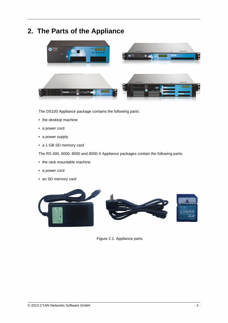
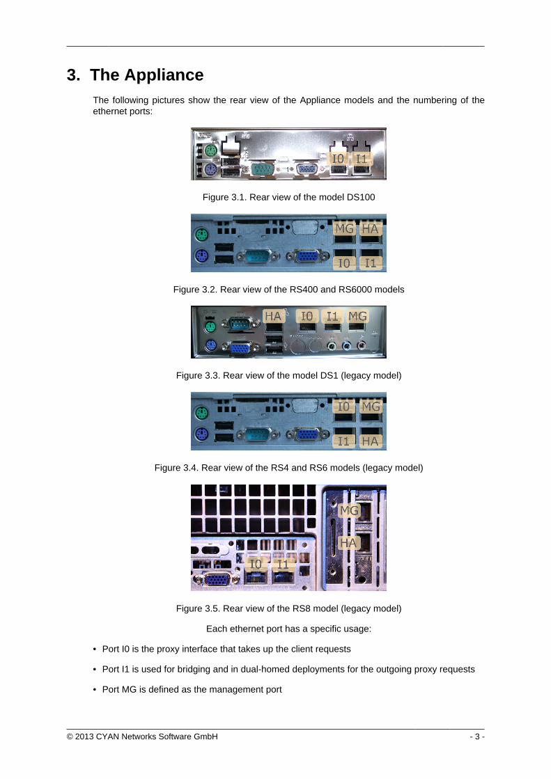
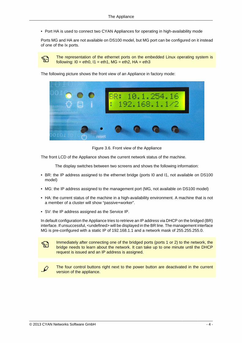
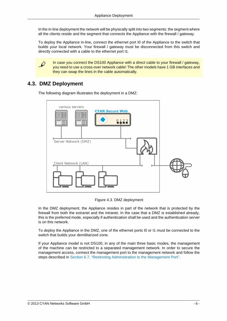
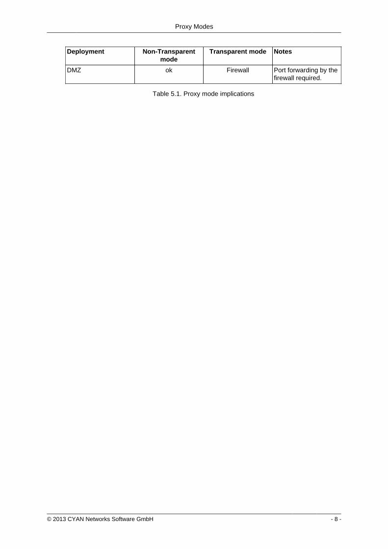
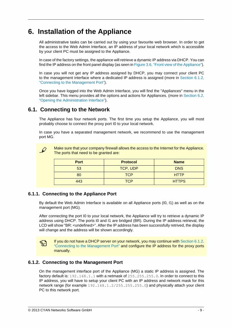
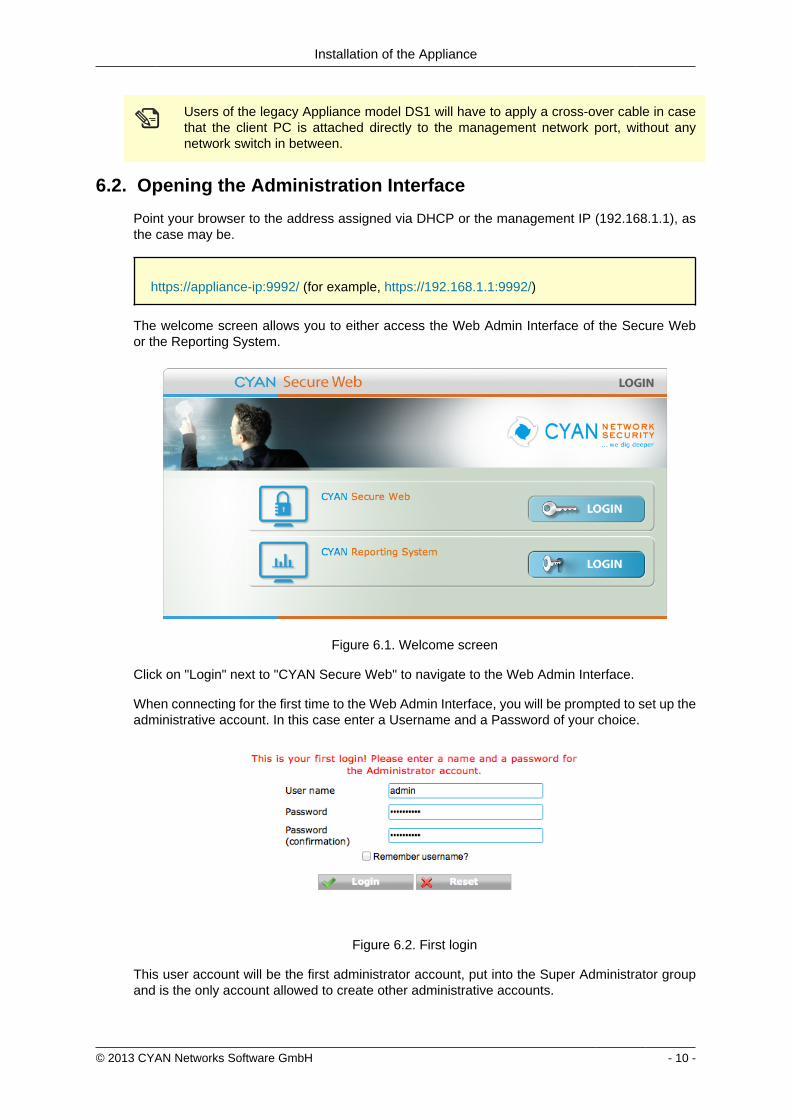
Installation of the Appliance
copy 2013 CYAN Networks Software GmbH - 10 -
Users of the legacy Appliance model DS1 will have to apply a cross-over cable in casethat the client PC is attached directly to the management network port without anynetwork switch in between
62 Opening the Administration Interface
Point your browser to the address assigned via DHCP or the management IP (19216811) asthe case may be
httpsappliance-ip9992 (for example https192168119992)
The welcome screen allows you to either access the Web Admin Interface of the Secure Webor the Reporting System
Figure 61 Welcome screen
Click on Login next to CYAN Secure Web to navigate to the Web Admin Interface
When connecting for the first time to the Web Admin Interface you will be prompted to set up theadministrative account In this case enter a Username and a Password of your choice
Figure 62 First login
This user account will be the first administrator account put into the Super Administrator groupand is the only account allowed to create other administrative accounts
Installation of the Appliance
copy 2013 CYAN Networks Software GmbH - 11 -
It is extremely important not to forget the Super Administrator password While forAdministrator accounts can be the password changed by the Super Administrator atany time there is no quick and easy password recovery procedure for the SuperAdministrator account itself If this password is lost it is necessary to connect a CR-Rom drive over USB boot up a Linux distribution mount the file system and set a newpassword or alternatively send the whole Appliance back to Cyan Networks for repair
On Secure Web Appliances an additional console account csupport will be enabled with the samepassword The Appliance can be accessed via SSH protocol using this account (for example formaintenance purposes) For more information see Section A11 ldquoAccess via SSHrdquo
Figure 63 First login csupport account
Please read and acknowledge the End User License Agreement (EULA) that is shown after thefirst login Buttons to acknowledge the EULA are at the end of the document
Figure 64 EULA
Installation of the Appliance
copy 2013 CYAN Networks Software GmbH - 12 -
63 Secure Web License
Secure Web requires a valid license to operate In case you have not received your licenseinformation and would like to evaluate Secure Web please browse to the location
httpwwwcyan-networkscomregistration
and follow the instructions on the screen After a successful completion of the registration a keyfile that includes the evaluation license will be sent to your email address
In order to activate Secure Web with a valid license got to menu ServicesAdminLicense andupload the key file that is attached to the email you received after clicking the Secure Webbutton
In case you received a ZIP archive with your license do not uncompress it Thearchive contains your Secure Web license and any additional license that you may havepurchased and must be uploaded to Secure Web without uncompressing it on your own
Figure 65 Secure Web License
Immediately after uploading the Secure Web license the Appliance will start updating the URLdatabase The amount of downloaded data is about 100 MB so this can take several minutesdepending on the speed of your Internet connection
64 User Support
The Appliance machines come with a pre-configured user named csupport The primary purposeof this user is to provide access to the machine for the CYAN Networks support team The supportuser however can also be used by yourself to get access to the machine for troubleshooting
For the support user we installed the public key of the CYAN Networks support team It is thereforenot necessary to provide us with the password of the machine The authentication is instead doneby using publicprivate-key authentication
The support user is enabled by default and set to the password of the first administrative useraccount that has been created on the first login To disable the user got to menu AppliancesMaintenanceAppliance Accounts
Installation of the Appliance
copy 2013 CYAN Networks Software GmbH - 13 -
Figure 66 Disabling the support user
In a typical customer environment the proxy machine is located somewhere within the network orin the DMZ in any case behind a firewall In case you would like to provide the CYAN Networkssupport team with access to your machine please take care of a proper mapping of the connectionfor SSH from the public Internet to the Appliance machine
Due to security reasons the support user is disabled in the factory defaults but enabledduring the first login
We recommend that you leave the support user enabled prior to changing any networksettings leaving you with a possibility to recover an access to the machine without havingto reset it to the factory defaults
65 Changing the IP Address(es)
In order to change the IP address of your Appliance navigate to the menu ApplianceNetworkInterfaces
Figure 67 Network interfaces
After saving the changes the appliance will immediately reconfigure itself and apply the newIP configuration It takes the BR interface approximately 30 secondsto learn the network layoutThen you will have to reconnect to the Web Admin Interface on the new IP address
In case you setup a static IP address do not forget to adjust the DNS settings accordingly(see Section 66 ldquoSetting up the DNSrdquo)
Installation of the Appliance
copy 2013 CYAN Networks Software GmbH - 14 -
After changing the IP address the machine might be inaccessible by your client PC If youhave made a mistake please refer to Section A2 ldquoRecover from an invalid IP addressrdquoin order to manually reset the IP configuration
66 Setting up the DNS
For static network configurations you may specify up to three domain name servers in the menuAppliancesNetworkDNS In DHCP environments DNS servers are usually set up automatically
Figure 68 DNS Setup
67 Restricting Administration to the Management Port
The factory default allows the access to the Web Admin Interface on the bridge ports as well ason the management port In order to restrict the access only to the management port
1 Open the menu AppliancesNetworkFirewall
2 Disable the flag Allow management from IF0IF1 This will deny any access to the WebAdmin Interface that arrives on one of the bridged ports
Figure 69 Bind management on management interface
Installation of the Appliance
copy 2013 CYAN Networks Software GmbH - 15 -
The management interface does not support a gateway setting Access is enabled solelyfrom the management network segment
Make sure that you are connected via the management port of the Appliance Afterdisabling management on the proxy ports (I0 and I1) you will no longer have access tothe Web Admin Interface via this ports
copy 2013 CYAN Networks Software GmbH - 16 -
7 Configuring the Proxy ServiceCYAN Secure Web consists of a number of services that build the proxy web filtering andweb security product (Secure Web Proxy) All services and corresponding components can beconfigured via the Services menu found on the left
Figure 71 Services menu
71 Service Proxy
In most situations the Secure Web Proxy has no direct access to the Internet At least a companyfirewall is located between the proxy system and Internet access Sometimes an additionalupstream proxy needs to be used for an access
From the Secure Web Proxy access to the following resources is required for operationalpurposes Please make sure that access to these resources is allowed on any upstream firewallor proxy system
bull servicecyan-networkscom - TCP port 80 (HTTP) TCP port 443 (HTTPS)
bull appliancecyan-networkscom - TCP port 80 (HTTP)
bull debcyan-networkscom - TCP port 80 (HTTP)
In some situations the Secure Web Proxy has no direct access to the Internet and an upstreamproxy is needed for requests to CYAN update services In that case the parameters found in themenu ServicesAdminService Proxy need to be configured accordingly
Figure 72 Service Proxy
Configuring the Proxy Service
copy 2013 CYAN Networks Software GmbH - 17 -
Enable the use of an upstream proxy and specify the host and the port information in the dialogabove If the upstream proxy requires an authenticated users in order to be allowed to accessthe Internet this credentials have to be added here too
Only Basic Authentication is supported for upstream proxy access If unsure please askyour upstream proxy administrator for details on how to authenticate on the system
72 Activating the Anti-Virus Engine
The Appliance comes pre-installed with the Clam AV engine To enable virus scanning navigateto the menu ServicesProxy SettingsAnti Virus and enable the scan engine Please make surethat the selected Virus engine is set to External Scanner as shown in the screenshot below
Figure 73 Anti Virus Engine
In order for you to evaluate the ESET anti virus engine please send an e-mail tosalescyan-networkscom for a trial license
73 Testing your Installation
After you have finished configuring the Appliance donrsquot forget to press the Apply button on topof the Web Admin Interface Without this action the configuration changes are not applied to theSecure Web components
Figure 74 Apply button
Configuring the Proxy Service
copy 2013 CYAN Networks Software GmbH - 18 -
To test your installation all you need to do is to point your Internet browser to your newly setupAppliance A short guide about how to configure some of the most used browsers follows
731 Setting up browser
7311 Internet Explorer
Figure 75 Proxy setup - Internet Explorer
To configure an Internet Explorer browser to use the newly setup Appliance as a proxy servergo to menu Tools Internet Options then navigate to tab Connections and click on the buttonLAN settings In the dialog that appears check the Use proxy server for your LANhellip checkboxfill the IP address of the Appliance and port
Figure 75 ldquoProxy setup - Internet Explorerrdquo only contains a sample IP address TheIP address of your Appliance may differ Please fill in the IP in the Manual proxyconfiguration field accordingly
Configuring the Proxy Service
copy 2013 CYAN Networks Software GmbH - 19 -
7312 Mozilla Firefox
Figure 76 Proxy setup - Mozilla Firefox
To configure a Mozilla Firefox browser to use the newly setup Appliance as a proxy server go tomenu Tools Options then navigate to tab Advanced sub tab Network and in Connection boxclick on the button Settingshellip In the dialog that appears select Manual proxy configuration fill theIP address of the Appliance port and check the Use proxy for all protocols checkbox
Configuring the Proxy Service
copy 2013 CYAN Networks Software GmbH - 20 -
7313 Google Chrome
Figure 77 Proxy setup - Google Chrome
To configure a Google Chrome browser to use the newly setup Appliance as a proxy server goto menu Settings at the bottom of the page click on Show advanced settings scroll down toNetwork heading and click on the Change proxy settingshellip button The rest of the configurationis the same as for Internet Explorer browser
Configuring the Proxy Service
copy 2013 CYAN Networks Software GmbH - 21 -
7314 Opera
Figure 78 Proxy setup - Opera
To configure an Opera browser to use the newly setup Appliance as a proxy server go tomenu Settings Preferenceshellip then navigate to tab Advanced select Network in the list clickon the Proxy Servershellip button In the dialog that appears check HTTP Use this proxy for allconnections and fill the IP address of the Appliance and port
7315 Windows Domain
If you have several computer connected to a Windows Domain and you are using Internet Exploreror Google Chrome browsers the configuration of these browsers can be done also on the DomainController Let us assume the following example Windows Domain
bull One domain called ictlocal
bull One Organizational Unit (OU) within the domain called company
bull One Security Group Computers that is part of the OU company
bull Any number of computers that are placed in the Security Group Computers and on whichshould be the proxy settings be changed
To successfully set the proxy settings on all the computers within the companyComputers groupthe following steps are necessary
Configuring the Proxy Service
copy 2013 CYAN Networks Software GmbH - 22 -
First open the Group Policy Management Console Click Start click Runhellip type gpmcmscand press OK
If the Group Policy Management Console fails to start especially in the MicrosoftWindows 2003 Server you need to install it first For the Microsoft Windows 2003 Serverit can be downloaded from httpwwwmicrosoftcomen-usdownloaddetailsaspxid=21895
In the Group Policy Management Console add a new Group Policy Object (GPO) Navigate toGroup Policy Objects right click in the Contents tab and select New as showed in the followingfigure
Figure 79 Adding a new GPO
Input new name for the GPO (for example Set proxy) Now right click the newly createdGPO select Edithellip and navigate to User Configuration Windows Settings Internet ExplorerMaintenance Double click in the list on Proxy Settings and add the IP address of the Applianceas showed in the Figure 710 ldquoSetting the proxy IP addressrdquo
Figure 710 Setting the proxy IP address
Configuring the Proxy Service
copy 2013 CYAN Networks Software GmbH - 23 -
Now it is necessary to link the Set proxy GPO to the desired OU (in this example OU company)It can be done simply by dragging the GPO and dropping it on the desired OU The other way isright clicking the OU in the list selecting Link an Existing GPOhellip and selecting the Set proxyGPO from the list The following figure shows the desired result
Figure 711 Configuring the GPO
By default the GPO is restricted to all objects present in the Authenticated Users group Thisgroup should cover all the objects (Users Computers etc) that can successfully connect to thedomain To limit the GPO just to a group of selected computers (in this example grouped in theSecurity Group Computers) in the GPO view tab Scope click on the Addhellip button and selectthe appropriate Security Group You can also remove the Authenticated Users group with theRemove button
Please note that depending on the Active Directory settings it may take up to 20 minutesto see the changes on the targeted computers and a re-login may be required after thistime To speed up the changes it may help to issue command gpupdate force on thetargeted computers (but it is not required)
732 Testing access
Now enter some URL (for example httpwwwcnncom) into the address bar and press Enter toload the web page If everything works correctly you will be served a blocking page because inthe default profile defaultrestrictive all categories are blocked
Configuring the Proxy Service
copy 2013 CYAN Networks Software GmbH - 24 -
Figure 712 Category blocking page
Since Soft Use Policy is enabled in the defaultrestrictive profile you may now click on click hereto access the page regardless of the profile settings denying it
To test the Anti Virus engine direct your browser to httpwwweicarorgdownloadeicarcom andacknowledge the Soft Use Policy that will allow you to download the content even though Archiveis not an allowed Application Type in the defaultrestrictive profile This link contains harmlesstesting code that was designed specifically for testing reactions of anti-virus engines There is noneed to be concerned that you will access a page with an actual virus on it
Figure 713 AV blocking of eicarcom download
Configuring the Proxy Service
copy 2013 CYAN Networks Software GmbH - 25 -
After the virus scanning will take place and if the scanning is successful the download will bedenied from the Anti Virus engine
Only integrated anti virus engines like ESET and Avira are capable of returning thevirus name
For performance reasons we strongly recommend you usage of the integrated Anti Virusengine
In case of any troubles please refer to the troubleshoot section of this document (see Appendix ATroubleshooting) or contact support at supportcyan-networkscom for help
copy 2013 CYAN Networks Software GmbH - 26 -
8 Initial Configuration
81 Initial Authentication Setup
Secure Web is installed on the Appliance with a default configuration This configuration includesfor the purpose of authentication an IP List instance named ldquoIP Listrdquo with one IP list namedldquoglobalrdquo representing ldquothe worldrdquo (00000) You can access this default instance by navigatinginto the menu ServicesAuthenticationInstances double clicking the IP list instance in the listand navigating to the IP List tab (as shown in the following figure)
Figure 81 IP Instance default configuration
According to the order of evaluation as defined in Section 83 ldquoInitial Profile Assignment Setuprdquothe IP List instance is evaluated first Consequently the global IP list which matches any IPaddress will affect all requests
82 Initial Profile Setup
Complementary to the default authentication configuration there is also a default setup of accessrules The profile tree shows the top level profile named organization and a sibling calleddefaultrestrictive
Figure 82 Profile default configuration
As shown in the Figure 82 ldquoProfile default configurationrdquo the defaultrestrictive profile appliesa rather strict type of Internet access by blocking all categories that are available in the CYANNetworks URL database
The following figure shows the General dialog found at Services Authentication Settingsincluding the setting for the default profile which gets applied to all connections without a dedicatedprofile assignment In this case it is the default defaultrestrictive profile
Initial Configuration
copy 2013 CYAN Networks Software GmbH - 27 -
Figure 83 Default profile used
83 Initial Profile Assignment Setup
Per default all requests served through the Secure Web Proxy are restricted by thedefaultrestrictive profile as set up in the General dialog found in Service Authentication Settings(see Section 82 ldquoInitial Profile Setuprdquo)
To assign profiles to different users groups or IPs in the network the administrator has to set upauthentication and assign profiles to the user objects
The following figure shows an example setup of an IP List authentication instance andassignments based on the IP objects It can be created in the menu Service Authentication Instances
Figure 84 Example IP List instance
In this example four IP objects are created based on the layout of the IP network A network forservers and QA machines is created and two single IP objects represent workstations
Initial Configuration
copy 2013 CYAN Networks Software GmbH - 28 -
In the following figure the server and QA networks are assigned to the defaultrestrictive profileThis profile is rather restrictive and blocks all categories per default This assignment can be donein the menu Services Profile Assignment
Figure 85 Example IP profile assignments
The two workstations in this example setup are assigned to the organisation profile which isa very relaxed setup as this profile allows any request made to the Secure Web Proxy Profileassignment can be modified by selecting some Authentication Instance from the list and usingappropriate action from the context menu New profile can be assigned by selecting Assign oneprofile existing profile assignment can be removed by selecting Remove profiles from selecteditem(s) More advanced manipulation can be done in Assign profiles with time rangeshellip
After finishing all desired changes do not forget to save them all using the Save button and thento apply them using the Apply button in the top right corner of the page
copy 2013 CYAN Networks Software GmbH - 29 -
9 Updating Upgrading the ApplianceIn order to get the latest product version of your CYAN Appliance go to the menu Appliances Maintenance Firmware
To start the update you have to press the Upgrade button as shown on the following figure
Figure 91 Firmware upgrade screen
After pressing the Upgrade button you will be taken to a different screen where you can performthe actual update of your Appliance (see Figure 92 ldquoUpgrade Service screen - upgraderdquo)
Pressing the Upgrade button will start an update procedure that includes completeshutdown of all services running on the Appliance This means any proxy functionalitywill unavailable until restart of the Appliance is performed
Again press the Upgrade button You will be informed about the ongoing update in the boxbellow the button In the example screen no update was neccessary and no new packages weredownloaded
Figure 92 Upgrade Service screen - upgrade
After the update is finished you are advised to restart your Appliance This can be performed byclicking the Restart button that appears below the information box (see the following figure)
Figure 93 Upgrade Service screen - upgrade
Updating Upgrading the Appliance
copy 2013 CYAN Networks Software GmbH - 30 -
When the restart of the Appliance is completed you can navigate back to the Web Admin Interfaceusing the browser navigation button
There is no need to perform periodic checks if updates are available Information aboutavailable updates of the Appliance can be found in the CYAN Networks newsletter It isnecessary to register in the company web pages to subscribe to it Please visit httpwwwcyan-networkscomindexphpenmy-cyan to register (registration is for free)
copy 2013 CYAN Networks Software GmbH - 31 -
10 Starting the Reporting SystemThe initial configuration of the appliance includes a pre-configured but yet inactive ReportingSystem The following actions need to be completed to activate the Reporting System
1 Setting up the Reporting Database
2 Enabling the Log Feed Service
It is strongly recommended to install the reporting database on a separate system Thisespecially applies for cluster setups where a local database setup is highly discouragedA local database system can cause performance impacts when reports are calculatedand is not synchronised in cluster environments
101 Login to the Reporting System
Point your browser to the address assigned via DHCP or the management IP as the case maybe Replace ltappliance-ipgt in the following URL with the real IP address of your Appliance
httpsltappliance-ipgt9992 (for example https 192168119992)
The welcome screen allows you to either access the Secure Web Web Admin Interface or theReporting System
Figure 101 Welcome screen
Click on Login next to CYAN Reporting System to navigate to the Web Admin Interface of theReporting System
The Reporting System uses different login credentials than the Secure Web You may want toassign a different password to the Secure Web login in order restrict the administration of themachine parameters and the reporting to different people
The default login values after setup are
bull User admin
Starting the Reporting System
copy 2013 CYAN Networks Software GmbH - 32 -
bull Password admin
We strongly recommended to change the administrator password as soon as possibleNavigate to the menu Users User and double-click on the admin user or click on theperson-shaped icon next to your login name in the top right corner of the screen to changethe password
102 Setting up the Reporting Database
Figure 102 Setup the reporting database
If you have not setup any database access previously at login you will be informed aboutincorrect values (as seen in figure Figure 102 ldquoSetup the reporting databaserdquo) There are manydifferent database engines supported for using the Reporting System
bull PostgreSQL 80 or higher
bull Microsoft SQL Server 2005 or higher
bull MySQL 50 or higher
bull Oracle
bull DB2
bull H2 Database
For each database engine there is available a short quide what SQL commands to issue tocorrectly make the initial database setup You can test the settings using the Test button
The configuration of the Reporting System database assumes you already have setupa database engine of your choice and you can connect to it If after filling in allrequired information a connection error still appears please check all the login credentialpriviledges firewall settings and whether the database engine daemon is running
Whenever any new version of the Reporting System should require any changes to the databaseyour explicit confirmation is requested in order to proceed with the upgrade That will be mostlikely your case since there is no database structure yet and it needs to be created An exampleof such upgrade request shows the following figure
Starting the Reporting System
copy 2013 CYAN Networks Software GmbH - 33 -
Figure 103 Upgrade of the reporting database
Database upgrades may take a long time and can cause significant impact on theoperation and performance of the system Therefore the Reporting System will neverupgrade the database automatically but leave this decision to the administrator
After a successful completion of the setup upgrade of the database a Login button appearsat the end of the page and allows you to go to the login screen
103 Enabling the Log-Feeder
In order to activate the import of the reporting information into the reporting database the logfeeder service of Secure Web must be enabled This service picks up the log files generated bySecure Web and feeds them into the reporting database
Change to the Secure Web administrative interface select the menu Services Logging Reporting Log and browse to the dialog Log Feeder as shown in the following screenshot
Figure 104 Log feeder
The default values in this dialog are prepared to operate with the Reporting System on the samemachine In case you want to run the Reporting System on a separate machine please refer tothe Secure Web Reference Guide that describes the necessary steps
Do not forget to save any changes you have made by the Save button and then apply them usingthe Apply button
The first time you enable the Log-Feeder it may time some time to generate output from all theavailable logs
copy 2013 CYAN Networks Software GmbH - 34 -
Appendix A Troubleshooting
A1 Getting access to the command line
A11 Access via SSH
The Appliance can be accessed using SSH protocol This access is enabled by the factorydefaults During the initial setup is created a special user account in the Appliances system withusername csupport and the same password as the one used for Super Administrator accountin the Web Admin Interface (in the following text denoted as Password) For connecting to theAppliance via SSH you also need to know the Appliances IP address (for example 19216811in the following text denoted as ltappliance-ipgt)
A111 From UnixLinux
Accessing the Appliance from a Unix based system is fairly easy In the command line issue thefollowing command
ssh csupportltappliance-ipgt
If this is the first time you are connecting to the Appliance via SSH from current system confirmthe security warning and input the Password when asked to
A112 From Microsoft Windows
Accessing the Appliance via SSH from a Windows system is a little more complicated Windowssystems do not have by default installed any SHH client programm so you will need to obtainone One of the most popular ones is a freeware software called PuTTY which does not requireany installation All versions are available for download from the following web page
httpwwwchiarkgreenendorguk~sgtathamputtydownloadhtml
A direct link to the latest executable 32bit version for Windows is following
httptheearthli~sgtathamputtylatestx86puttyexe
When the download is complete run the downloaded executable and the SSH client login screenshould appear (as you can see in Figure A1 ldquoPuTTY windowrdquo) In the window input logininformation in the Host Name (or IP address) field Use the same format (substitute the exampleIP address 19216811 with the real IP address of your Appliance) Then click on the Open buttonconfirm a security warning if it appears and input the Password when asked for one
Troubleshooting
copy 2013 CYAN Networks Software GmbH - 35 -
Figure A1 PuTTY window
Once you are logged in to the system you will be able to see a simple text menu providing quickaccess to some of the useful maintenance functions
Figure A2 Console main menu
Troubleshooting
copy 2013 CYAN Networks Software GmbH - 36 -
A12 Access using monitor and keyboard
With a keyboard and a monitor attached to your appliance machine you may login to thecommand line using the credentials of the csupport user (as described in the previous section)
After logging in to the system you will be able to see and operate the same way as shown inthe previous section
A2 Recover from an invalid IP address
In case that you have set up an IP address which is not reachable by your client PC there is analternative way to change the IP address of the appliance by using the command line interface(see Section A1 ldquoGetting access to the command linerdquo)
If you have already successfully logged into the system using the csupport account navigateto menu Network management Display interfaces to see the list of available interfaces on theAppliance Make a note of the name of the interface which IP address you want to change
Figure A3 Network interfaces
Press any key to return to the previous menu and this time choose Temporarily change networkconfiguration menu item You will be asked for a name of the interface you have noted down inthe previous step new IP address network mask and optionally gateway IP address
If you are connected to the appliance via SSH and you changed the IP address of theinterface to which you are currently connected the connection will be dropped withoutany warning and you will have to reconnect to the newly set up IP address
After changing the IP address of the Appliances port via console menu you haveto change the IP address again in the Web Admin Interface Please refer to theSection 65 ldquoChanging the IP Address(es)rdquo to get information about changing the IPaddress permanently Any changes done using the console menu will last just until areboot of the Appliance
copy 2013 CYAN Networks Software GmbH - 37 -
Appendix B Contact data
B1 How to contact our sales department
Tel +43 (1) 33933-0
Email salescyan-networkscom
B2 How to contact our support department
Tel +43 (1) 33933-333
Email supportcyan-networkscom
B21 Getting Support
In case you should have any technical problems or questions and would like to get support fromour team we kindly ask you to provide us with the following information
bull Description of your question or problem
bull The version information of the product
bull The version information of Secure Web can be found after logging into the Web AdminInterface in the top part of the screen
Figure B1 Version information of the Secure Web
bull The version information of the Reporting System can be found after login in the top part ofthe screen of the Web Admin Interface
Figure B2 Version information of the Reporting System
bull All the information contained in the screen found in menu Services Services Overview
bull In the case authentication is activated provide us with the method in place (via Windows Agentvia Linux Agent etc)
bull The deployment method of the Appliance (Out-of-line In-Line DMZ)
bull The operation mode of the Appliance (dedicated mode transparent mode)
Contact data
copy 2013 CYAN Networks Software GmbH - 38 -
bull Information about the environment (proxy cascades that are used firewalls and gatewaysinvolved in the infrastructure that are of relevance to the Appliance)
The appliance interface provides the possibility to create a support package that includes theconfiguration and log files of the system This package can help us to track down the issue easierand faster Please attach this package to your e-mail
In order to create a support pack navigate to menu Appliances Maintenance Support and clickon the Download button You may select the files you want to provide to our support team andthen download a package which we kindly ask you to send to our support email address
Figure B3 Support Package
Further documentation about the product as well as technical white papers that describe certainuse cases can be found in our documentation repository on our homepage
httpwwwcyan-networkscomdocumentation
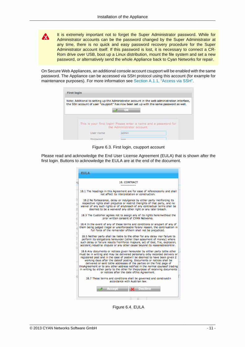
Installation of the Appliance
copy 2013 CYAN Networks Software GmbH - 11 -
It is extremely important not to forget the Super Administrator password While forAdministrator accounts can be the password changed by the Super Administrator atany time there is no quick and easy password recovery procedure for the SuperAdministrator account itself If this password is lost it is necessary to connect a CR-Rom drive over USB boot up a Linux distribution mount the file system and set a newpassword or alternatively send the whole Appliance back to Cyan Networks for repair
On Secure Web Appliances an additional console account csupport will be enabled with the samepassword The Appliance can be accessed via SSH protocol using this account (for example formaintenance purposes) For more information see Section A11 ldquoAccess via SSHrdquo
Figure 63 First login csupport account
Please read and acknowledge the End User License Agreement (EULA) that is shown after thefirst login Buttons to acknowledge the EULA are at the end of the document
Figure 64 EULA
Installation of the Appliance
copy 2013 CYAN Networks Software GmbH - 12 -
63 Secure Web License
Secure Web requires a valid license to operate In case you have not received your licenseinformation and would like to evaluate Secure Web please browse to the location
httpwwwcyan-networkscomregistration
and follow the instructions on the screen After a successful completion of the registration a keyfile that includes the evaluation license will be sent to your email address
In order to activate Secure Web with a valid license got to menu ServicesAdminLicense andupload the key file that is attached to the email you received after clicking the Secure Webbutton
In case you received a ZIP archive with your license do not uncompress it Thearchive contains your Secure Web license and any additional license that you may havepurchased and must be uploaded to Secure Web without uncompressing it on your own
Figure 65 Secure Web License
Immediately after uploading the Secure Web license the Appliance will start updating the URLdatabase The amount of downloaded data is about 100 MB so this can take several minutesdepending on the speed of your Internet connection
64 User Support
The Appliance machines come with a pre-configured user named csupport The primary purposeof this user is to provide access to the machine for the CYAN Networks support team The supportuser however can also be used by yourself to get access to the machine for troubleshooting
For the support user we installed the public key of the CYAN Networks support team It is thereforenot necessary to provide us with the password of the machine The authentication is instead doneby using publicprivate-key authentication
The support user is enabled by default and set to the password of the first administrative useraccount that has been created on the first login To disable the user got to menu AppliancesMaintenanceAppliance Accounts
Installation of the Appliance
copy 2013 CYAN Networks Software GmbH - 13 -
Figure 66 Disabling the support user
In a typical customer environment the proxy machine is located somewhere within the network orin the DMZ in any case behind a firewall In case you would like to provide the CYAN Networkssupport team with access to your machine please take care of a proper mapping of the connectionfor SSH from the public Internet to the Appliance machine
Due to security reasons the support user is disabled in the factory defaults but enabledduring the first login
We recommend that you leave the support user enabled prior to changing any networksettings leaving you with a possibility to recover an access to the machine without havingto reset it to the factory defaults
65 Changing the IP Address(es)
In order to change the IP address of your Appliance navigate to the menu ApplianceNetworkInterfaces
Figure 67 Network interfaces
After saving the changes the appliance will immediately reconfigure itself and apply the newIP configuration It takes the BR interface approximately 30 secondsto learn the network layoutThen you will have to reconnect to the Web Admin Interface on the new IP address
In case you setup a static IP address do not forget to adjust the DNS settings accordingly(see Section 66 ldquoSetting up the DNSrdquo)
Installation of the Appliance
copy 2013 CYAN Networks Software GmbH - 14 -
After changing the IP address the machine might be inaccessible by your client PC If youhave made a mistake please refer to Section A2 ldquoRecover from an invalid IP addressrdquoin order to manually reset the IP configuration
66 Setting up the DNS
For static network configurations you may specify up to three domain name servers in the menuAppliancesNetworkDNS In DHCP environments DNS servers are usually set up automatically
Figure 68 DNS Setup
67 Restricting Administration to the Management Port
The factory default allows the access to the Web Admin Interface on the bridge ports as well ason the management port In order to restrict the access only to the management port
1 Open the menu AppliancesNetworkFirewall
2 Disable the flag Allow management from IF0IF1 This will deny any access to the WebAdmin Interface that arrives on one of the bridged ports
Figure 69 Bind management on management interface
Installation of the Appliance
copy 2013 CYAN Networks Software GmbH - 15 -
The management interface does not support a gateway setting Access is enabled solelyfrom the management network segment
Make sure that you are connected via the management port of the Appliance Afterdisabling management on the proxy ports (I0 and I1) you will no longer have access tothe Web Admin Interface via this ports
copy 2013 CYAN Networks Software GmbH - 16 -
7 Configuring the Proxy ServiceCYAN Secure Web consists of a number of services that build the proxy web filtering andweb security product (Secure Web Proxy) All services and corresponding components can beconfigured via the Services menu found on the left
Figure 71 Services menu
71 Service Proxy
In most situations the Secure Web Proxy has no direct access to the Internet At least a companyfirewall is located between the proxy system and Internet access Sometimes an additionalupstream proxy needs to be used for an access
From the Secure Web Proxy access to the following resources is required for operationalpurposes Please make sure that access to these resources is allowed on any upstream firewallor proxy system
bull servicecyan-networkscom - TCP port 80 (HTTP) TCP port 443 (HTTPS)
bull appliancecyan-networkscom - TCP port 80 (HTTP)
bull debcyan-networkscom - TCP port 80 (HTTP)
In some situations the Secure Web Proxy has no direct access to the Internet and an upstreamproxy is needed for requests to CYAN update services In that case the parameters found in themenu ServicesAdminService Proxy need to be configured accordingly
Figure 72 Service Proxy
Configuring the Proxy Service
copy 2013 CYAN Networks Software GmbH - 17 -
Enable the use of an upstream proxy and specify the host and the port information in the dialogabove If the upstream proxy requires an authenticated users in order to be allowed to accessthe Internet this credentials have to be added here too
Only Basic Authentication is supported for upstream proxy access If unsure please askyour upstream proxy administrator for details on how to authenticate on the system
72 Activating the Anti-Virus Engine
The Appliance comes pre-installed with the Clam AV engine To enable virus scanning navigateto the menu ServicesProxy SettingsAnti Virus and enable the scan engine Please make surethat the selected Virus engine is set to External Scanner as shown in the screenshot below
Figure 73 Anti Virus Engine
In order for you to evaluate the ESET anti virus engine please send an e-mail tosalescyan-networkscom for a trial license
73 Testing your Installation
After you have finished configuring the Appliance donrsquot forget to press the Apply button on topof the Web Admin Interface Without this action the configuration changes are not applied to theSecure Web components
Figure 74 Apply button
Configuring the Proxy Service
copy 2013 CYAN Networks Software GmbH - 18 -
To test your installation all you need to do is to point your Internet browser to your newly setupAppliance A short guide about how to configure some of the most used browsers follows
731 Setting up browser
7311 Internet Explorer
Figure 75 Proxy setup - Internet Explorer
To configure an Internet Explorer browser to use the newly setup Appliance as a proxy servergo to menu Tools Internet Options then navigate to tab Connections and click on the buttonLAN settings In the dialog that appears check the Use proxy server for your LANhellip checkboxfill the IP address of the Appliance and port
Figure 75 ldquoProxy setup - Internet Explorerrdquo only contains a sample IP address TheIP address of your Appliance may differ Please fill in the IP in the Manual proxyconfiguration field accordingly
Configuring the Proxy Service
copy 2013 CYAN Networks Software GmbH - 19 -
7312 Mozilla Firefox
Figure 76 Proxy setup - Mozilla Firefox
To configure a Mozilla Firefox browser to use the newly setup Appliance as a proxy server go tomenu Tools Options then navigate to tab Advanced sub tab Network and in Connection boxclick on the button Settingshellip In the dialog that appears select Manual proxy configuration fill theIP address of the Appliance port and check the Use proxy for all protocols checkbox
Configuring the Proxy Service
copy 2013 CYAN Networks Software GmbH - 20 -
7313 Google Chrome
Figure 77 Proxy setup - Google Chrome
To configure a Google Chrome browser to use the newly setup Appliance as a proxy server goto menu Settings at the bottom of the page click on Show advanced settings scroll down toNetwork heading and click on the Change proxy settingshellip button The rest of the configurationis the same as for Internet Explorer browser
Configuring the Proxy Service
copy 2013 CYAN Networks Software GmbH - 21 -
7314 Opera
Figure 78 Proxy setup - Opera
To configure an Opera browser to use the newly setup Appliance as a proxy server go tomenu Settings Preferenceshellip then navigate to tab Advanced select Network in the list clickon the Proxy Servershellip button In the dialog that appears check HTTP Use this proxy for allconnections and fill the IP address of the Appliance and port
7315 Windows Domain
If you have several computer connected to a Windows Domain and you are using Internet Exploreror Google Chrome browsers the configuration of these browsers can be done also on the DomainController Let us assume the following example Windows Domain
bull One domain called ictlocal
bull One Organizational Unit (OU) within the domain called company
bull One Security Group Computers that is part of the OU company
bull Any number of computers that are placed in the Security Group Computers and on whichshould be the proxy settings be changed
To successfully set the proxy settings on all the computers within the companyComputers groupthe following steps are necessary
Configuring the Proxy Service
copy 2013 CYAN Networks Software GmbH - 22 -
First open the Group Policy Management Console Click Start click Runhellip type gpmcmscand press OK
If the Group Policy Management Console fails to start especially in the MicrosoftWindows 2003 Server you need to install it first For the Microsoft Windows 2003 Serverit can be downloaded from httpwwwmicrosoftcomen-usdownloaddetailsaspxid=21895
In the Group Policy Management Console add a new Group Policy Object (GPO) Navigate toGroup Policy Objects right click in the Contents tab and select New as showed in the followingfigure
Figure 79 Adding a new GPO
Input new name for the GPO (for example Set proxy) Now right click the newly createdGPO select Edithellip and navigate to User Configuration Windows Settings Internet ExplorerMaintenance Double click in the list on Proxy Settings and add the IP address of the Applianceas showed in the Figure 710 ldquoSetting the proxy IP addressrdquo
Figure 710 Setting the proxy IP address
Configuring the Proxy Service
copy 2013 CYAN Networks Software GmbH - 23 -
Now it is necessary to link the Set proxy GPO to the desired OU (in this example OU company)It can be done simply by dragging the GPO and dropping it on the desired OU The other way isright clicking the OU in the list selecting Link an Existing GPOhellip and selecting the Set proxyGPO from the list The following figure shows the desired result
Figure 711 Configuring the GPO
By default the GPO is restricted to all objects present in the Authenticated Users group Thisgroup should cover all the objects (Users Computers etc) that can successfully connect to thedomain To limit the GPO just to a group of selected computers (in this example grouped in theSecurity Group Computers) in the GPO view tab Scope click on the Addhellip button and selectthe appropriate Security Group You can also remove the Authenticated Users group with theRemove button
Please note that depending on the Active Directory settings it may take up to 20 minutesto see the changes on the targeted computers and a re-login may be required after thistime To speed up the changes it may help to issue command gpupdate force on thetargeted computers (but it is not required)
732 Testing access
Now enter some URL (for example httpwwwcnncom) into the address bar and press Enter toload the web page If everything works correctly you will be served a blocking page because inthe default profile defaultrestrictive all categories are blocked
Configuring the Proxy Service
copy 2013 CYAN Networks Software GmbH - 24 -
Figure 712 Category blocking page
Since Soft Use Policy is enabled in the defaultrestrictive profile you may now click on click hereto access the page regardless of the profile settings denying it
To test the Anti Virus engine direct your browser to httpwwweicarorgdownloadeicarcom andacknowledge the Soft Use Policy that will allow you to download the content even though Archiveis not an allowed Application Type in the defaultrestrictive profile This link contains harmlesstesting code that was designed specifically for testing reactions of anti-virus engines There is noneed to be concerned that you will access a page with an actual virus on it
Figure 713 AV blocking of eicarcom download
Configuring the Proxy Service
copy 2013 CYAN Networks Software GmbH - 25 -
After the virus scanning will take place and if the scanning is successful the download will bedenied from the Anti Virus engine
Only integrated anti virus engines like ESET and Avira are capable of returning thevirus name
For performance reasons we strongly recommend you usage of the integrated Anti Virusengine
In case of any troubles please refer to the troubleshoot section of this document (see Appendix ATroubleshooting) or contact support at supportcyan-networkscom for help
copy 2013 CYAN Networks Software GmbH - 26 -
8 Initial Configuration
81 Initial Authentication Setup
Secure Web is installed on the Appliance with a default configuration This configuration includesfor the purpose of authentication an IP List instance named ldquoIP Listrdquo with one IP list namedldquoglobalrdquo representing ldquothe worldrdquo (00000) You can access this default instance by navigatinginto the menu ServicesAuthenticationInstances double clicking the IP list instance in the listand navigating to the IP List tab (as shown in the following figure)
Figure 81 IP Instance default configuration
According to the order of evaluation as defined in Section 83 ldquoInitial Profile Assignment Setuprdquothe IP List instance is evaluated first Consequently the global IP list which matches any IPaddress will affect all requests
82 Initial Profile Setup
Complementary to the default authentication configuration there is also a default setup of accessrules The profile tree shows the top level profile named organization and a sibling calleddefaultrestrictive
Figure 82 Profile default configuration
As shown in the Figure 82 ldquoProfile default configurationrdquo the defaultrestrictive profile appliesa rather strict type of Internet access by blocking all categories that are available in the CYANNetworks URL database
The following figure shows the General dialog found at Services Authentication Settingsincluding the setting for the default profile which gets applied to all connections without a dedicatedprofile assignment In this case it is the default defaultrestrictive profile
Initial Configuration
copy 2013 CYAN Networks Software GmbH - 27 -
Figure 83 Default profile used
83 Initial Profile Assignment Setup
Per default all requests served through the Secure Web Proxy are restricted by thedefaultrestrictive profile as set up in the General dialog found in Service Authentication Settings(see Section 82 ldquoInitial Profile Setuprdquo)
To assign profiles to different users groups or IPs in the network the administrator has to set upauthentication and assign profiles to the user objects
The following figure shows an example setup of an IP List authentication instance andassignments based on the IP objects It can be created in the menu Service Authentication Instances
Figure 84 Example IP List instance
In this example four IP objects are created based on the layout of the IP network A network forservers and QA machines is created and two single IP objects represent workstations
Initial Configuration
copy 2013 CYAN Networks Software GmbH - 28 -
In the following figure the server and QA networks are assigned to the defaultrestrictive profileThis profile is rather restrictive and blocks all categories per default This assignment can be donein the menu Services Profile Assignment
Figure 85 Example IP profile assignments
The two workstations in this example setup are assigned to the organisation profile which isa very relaxed setup as this profile allows any request made to the Secure Web Proxy Profileassignment can be modified by selecting some Authentication Instance from the list and usingappropriate action from the context menu New profile can be assigned by selecting Assign oneprofile existing profile assignment can be removed by selecting Remove profiles from selecteditem(s) More advanced manipulation can be done in Assign profiles with time rangeshellip
After finishing all desired changes do not forget to save them all using the Save button and thento apply them using the Apply button in the top right corner of the page
copy 2013 CYAN Networks Software GmbH - 29 -
9 Updating Upgrading the ApplianceIn order to get the latest product version of your CYAN Appliance go to the menu Appliances Maintenance Firmware
To start the update you have to press the Upgrade button as shown on the following figure
Figure 91 Firmware upgrade screen
After pressing the Upgrade button you will be taken to a different screen where you can performthe actual update of your Appliance (see Figure 92 ldquoUpgrade Service screen - upgraderdquo)
Pressing the Upgrade button will start an update procedure that includes completeshutdown of all services running on the Appliance This means any proxy functionalitywill unavailable until restart of the Appliance is performed
Again press the Upgrade button You will be informed about the ongoing update in the boxbellow the button In the example screen no update was neccessary and no new packages weredownloaded
Figure 92 Upgrade Service screen - upgrade
After the update is finished you are advised to restart your Appliance This can be performed byclicking the Restart button that appears below the information box (see the following figure)
Figure 93 Upgrade Service screen - upgrade
Updating Upgrading the Appliance
copy 2013 CYAN Networks Software GmbH - 30 -
When the restart of the Appliance is completed you can navigate back to the Web Admin Interfaceusing the browser navigation button
There is no need to perform periodic checks if updates are available Information aboutavailable updates of the Appliance can be found in the CYAN Networks newsletter It isnecessary to register in the company web pages to subscribe to it Please visit httpwwwcyan-networkscomindexphpenmy-cyan to register (registration is for free)
copy 2013 CYAN Networks Software GmbH - 31 -
10 Starting the Reporting SystemThe initial configuration of the appliance includes a pre-configured but yet inactive ReportingSystem The following actions need to be completed to activate the Reporting System
1 Setting up the Reporting Database
2 Enabling the Log Feed Service
It is strongly recommended to install the reporting database on a separate system Thisespecially applies for cluster setups where a local database setup is highly discouragedA local database system can cause performance impacts when reports are calculatedand is not synchronised in cluster environments
101 Login to the Reporting System
Point your browser to the address assigned via DHCP or the management IP as the case maybe Replace ltappliance-ipgt in the following URL with the real IP address of your Appliance
httpsltappliance-ipgt9992 (for example https 192168119992)
The welcome screen allows you to either access the Secure Web Web Admin Interface or theReporting System
Figure 101 Welcome screen
Click on Login next to CYAN Reporting System to navigate to the Web Admin Interface of theReporting System
The Reporting System uses different login credentials than the Secure Web You may want toassign a different password to the Secure Web login in order restrict the administration of themachine parameters and the reporting to different people
The default login values after setup are
bull User admin
Starting the Reporting System
copy 2013 CYAN Networks Software GmbH - 32 -
bull Password admin
We strongly recommended to change the administrator password as soon as possibleNavigate to the menu Users User and double-click on the admin user or click on theperson-shaped icon next to your login name in the top right corner of the screen to changethe password
102 Setting up the Reporting Database
Figure 102 Setup the reporting database
If you have not setup any database access previously at login you will be informed aboutincorrect values (as seen in figure Figure 102 ldquoSetup the reporting databaserdquo) There are manydifferent database engines supported for using the Reporting System
bull PostgreSQL 80 or higher
bull Microsoft SQL Server 2005 or higher
bull MySQL 50 or higher
bull Oracle
bull DB2
bull H2 Database
For each database engine there is available a short quide what SQL commands to issue tocorrectly make the initial database setup You can test the settings using the Test button
The configuration of the Reporting System database assumes you already have setupa database engine of your choice and you can connect to it If after filling in allrequired information a connection error still appears please check all the login credentialpriviledges firewall settings and whether the database engine daemon is running
Whenever any new version of the Reporting System should require any changes to the databaseyour explicit confirmation is requested in order to proceed with the upgrade That will be mostlikely your case since there is no database structure yet and it needs to be created An exampleof such upgrade request shows the following figure
Starting the Reporting System
copy 2013 CYAN Networks Software GmbH - 33 -
Figure 103 Upgrade of the reporting database
Database upgrades may take a long time and can cause significant impact on theoperation and performance of the system Therefore the Reporting System will neverupgrade the database automatically but leave this decision to the administrator
After a successful completion of the setup upgrade of the database a Login button appearsat the end of the page and allows you to go to the login screen
103 Enabling the Log-Feeder
In order to activate the import of the reporting information into the reporting database the logfeeder service of Secure Web must be enabled This service picks up the log files generated bySecure Web and feeds them into the reporting database
Change to the Secure Web administrative interface select the menu Services Logging Reporting Log and browse to the dialog Log Feeder as shown in the following screenshot
Figure 104 Log feeder
The default values in this dialog are prepared to operate with the Reporting System on the samemachine In case you want to run the Reporting System on a separate machine please refer tothe Secure Web Reference Guide that describes the necessary steps
Do not forget to save any changes you have made by the Save button and then apply them usingthe Apply button
The first time you enable the Log-Feeder it may time some time to generate output from all theavailable logs
copy 2013 CYAN Networks Software GmbH - 34 -
Appendix A Troubleshooting
A1 Getting access to the command line
A11 Access via SSH
The Appliance can be accessed using SSH protocol This access is enabled by the factorydefaults During the initial setup is created a special user account in the Appliances system withusername csupport and the same password as the one used for Super Administrator accountin the Web Admin Interface (in the following text denoted as Password) For connecting to theAppliance via SSH you also need to know the Appliances IP address (for example 19216811in the following text denoted as ltappliance-ipgt)
A111 From UnixLinux
Accessing the Appliance from a Unix based system is fairly easy In the command line issue thefollowing command
ssh csupportltappliance-ipgt
If this is the first time you are connecting to the Appliance via SSH from current system confirmthe security warning and input the Password when asked to
A112 From Microsoft Windows
Accessing the Appliance via SSH from a Windows system is a little more complicated Windowssystems do not have by default installed any SHH client programm so you will need to obtainone One of the most popular ones is a freeware software called PuTTY which does not requireany installation All versions are available for download from the following web page
httpwwwchiarkgreenendorguk~sgtathamputtydownloadhtml
A direct link to the latest executable 32bit version for Windows is following
httptheearthli~sgtathamputtylatestx86puttyexe
When the download is complete run the downloaded executable and the SSH client login screenshould appear (as you can see in Figure A1 ldquoPuTTY windowrdquo) In the window input logininformation in the Host Name (or IP address) field Use the same format (substitute the exampleIP address 19216811 with the real IP address of your Appliance) Then click on the Open buttonconfirm a security warning if it appears and input the Password when asked for one
Troubleshooting
copy 2013 CYAN Networks Software GmbH - 35 -
Figure A1 PuTTY window
Once you are logged in to the system you will be able to see a simple text menu providing quickaccess to some of the useful maintenance functions
Figure A2 Console main menu
Troubleshooting
copy 2013 CYAN Networks Software GmbH - 36 -
A12 Access using monitor and keyboard
With a keyboard and a monitor attached to your appliance machine you may login to thecommand line using the credentials of the csupport user (as described in the previous section)
After logging in to the system you will be able to see and operate the same way as shown inthe previous section
A2 Recover from an invalid IP address
In case that you have set up an IP address which is not reachable by your client PC there is analternative way to change the IP address of the appliance by using the command line interface(see Section A1 ldquoGetting access to the command linerdquo)
If you have already successfully logged into the system using the csupport account navigateto menu Network management Display interfaces to see the list of available interfaces on theAppliance Make a note of the name of the interface which IP address you want to change
Figure A3 Network interfaces
Press any key to return to the previous menu and this time choose Temporarily change networkconfiguration menu item You will be asked for a name of the interface you have noted down inthe previous step new IP address network mask and optionally gateway IP address
If you are connected to the appliance via SSH and you changed the IP address of theinterface to which you are currently connected the connection will be dropped withoutany warning and you will have to reconnect to the newly set up IP address
After changing the IP address of the Appliances port via console menu you haveto change the IP address again in the Web Admin Interface Please refer to theSection 65 ldquoChanging the IP Address(es)rdquo to get information about changing the IPaddress permanently Any changes done using the console menu will last just until areboot of the Appliance
copy 2013 CYAN Networks Software GmbH - 37 -
Appendix B Contact data
B1 How to contact our sales department
Tel +43 (1) 33933-0
Email salescyan-networkscom
B2 How to contact our support department
Tel +43 (1) 33933-333
Email supportcyan-networkscom
B21 Getting Support
In case you should have any technical problems or questions and would like to get support fromour team we kindly ask you to provide us with the following information
bull Description of your question or problem
bull The version information of the product
bull The version information of Secure Web can be found after logging into the Web AdminInterface in the top part of the screen
Figure B1 Version information of the Secure Web
bull The version information of the Reporting System can be found after login in the top part ofthe screen of the Web Admin Interface
Figure B2 Version information of the Reporting System
bull All the information contained in the screen found in menu Services Services Overview
bull In the case authentication is activated provide us with the method in place (via Windows Agentvia Linux Agent etc)
bull The deployment method of the Appliance (Out-of-line In-Line DMZ)
bull The operation mode of the Appliance (dedicated mode transparent mode)
Contact data
copy 2013 CYAN Networks Software GmbH - 38 -
bull Information about the environment (proxy cascades that are used firewalls and gatewaysinvolved in the infrastructure that are of relevance to the Appliance)
The appliance interface provides the possibility to create a support package that includes theconfiguration and log files of the system This package can help us to track down the issue easierand faster Please attach this package to your e-mail
In order to create a support pack navigate to menu Appliances Maintenance Support and clickon the Download button You may select the files you want to provide to our support team andthen download a package which we kindly ask you to send to our support email address
Figure B3 Support Package
Further documentation about the product as well as technical white papers that describe certainuse cases can be found in our documentation repository on our homepage
httpwwwcyan-networkscomdocumentation
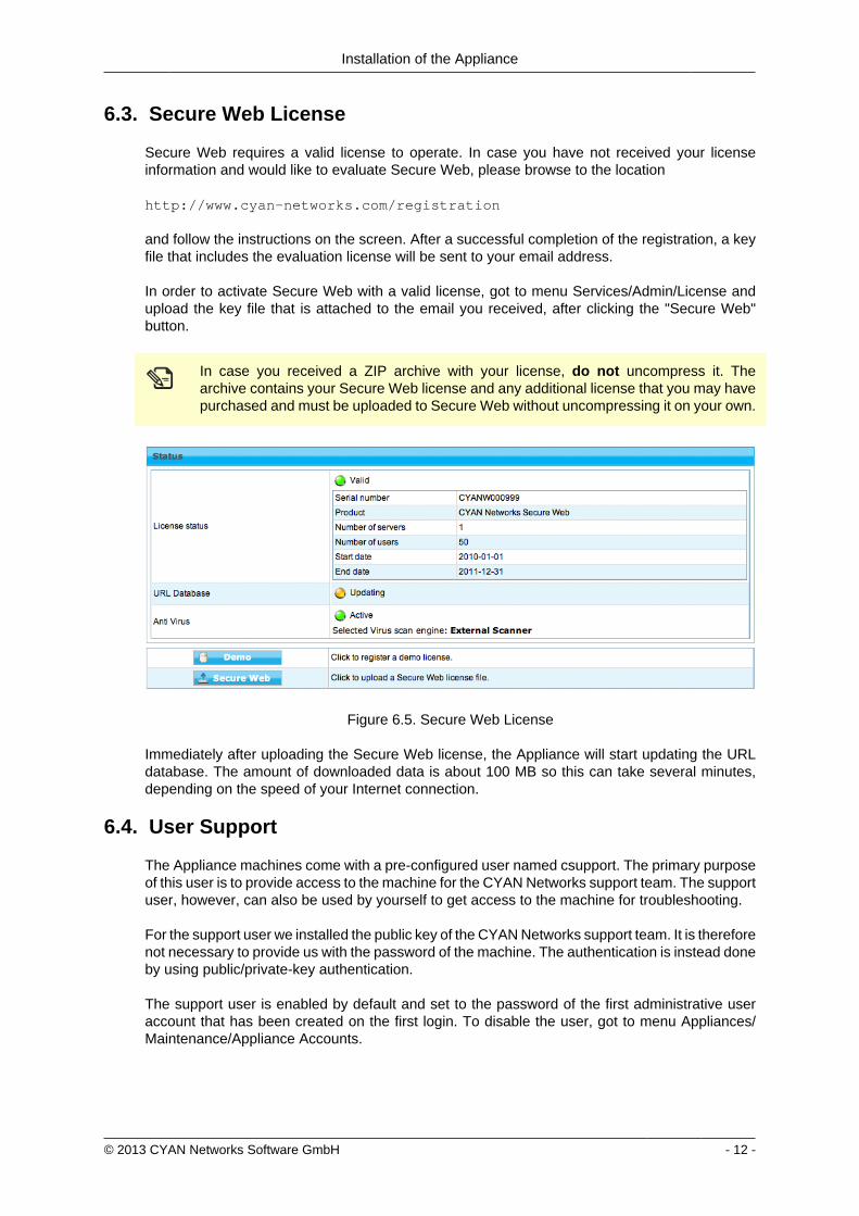
Installation of the Appliance
copy 2013 CYAN Networks Software GmbH - 12 -
63 Secure Web License
Secure Web requires a valid license to operate In case you have not received your licenseinformation and would like to evaluate Secure Web please browse to the location
httpwwwcyan-networkscomregistration
and follow the instructions on the screen After a successful completion of the registration a keyfile that includes the evaluation license will be sent to your email address
In order to activate Secure Web with a valid license got to menu ServicesAdminLicense andupload the key file that is attached to the email you received after clicking the Secure Webbutton
In case you received a ZIP archive with your license do not uncompress it Thearchive contains your Secure Web license and any additional license that you may havepurchased and must be uploaded to Secure Web without uncompressing it on your own
Figure 65 Secure Web License
Immediately after uploading the Secure Web license the Appliance will start updating the URLdatabase The amount of downloaded data is about 100 MB so this can take several minutesdepending on the speed of your Internet connection
64 User Support
The Appliance machines come with a pre-configured user named csupport The primary purposeof this user is to provide access to the machine for the CYAN Networks support team The supportuser however can also be used by yourself to get access to the machine for troubleshooting
For the support user we installed the public key of the CYAN Networks support team It is thereforenot necessary to provide us with the password of the machine The authentication is instead doneby using publicprivate-key authentication
The support user is enabled by default and set to the password of the first administrative useraccount that has been created on the first login To disable the user got to menu AppliancesMaintenanceAppliance Accounts
Installation of the Appliance
copy 2013 CYAN Networks Software GmbH - 13 -
Figure 66 Disabling the support user
In a typical customer environment the proxy machine is located somewhere within the network orin the DMZ in any case behind a firewall In case you would like to provide the CYAN Networkssupport team with access to your machine please take care of a proper mapping of the connectionfor SSH from the public Internet to the Appliance machine
Due to security reasons the support user is disabled in the factory defaults but enabledduring the first login
We recommend that you leave the support user enabled prior to changing any networksettings leaving you with a possibility to recover an access to the machine without havingto reset it to the factory defaults
65 Changing the IP Address(es)
In order to change the IP address of your Appliance navigate to the menu ApplianceNetworkInterfaces
Figure 67 Network interfaces
After saving the changes the appliance will immediately reconfigure itself and apply the newIP configuration It takes the BR interface approximately 30 secondsto learn the network layoutThen you will have to reconnect to the Web Admin Interface on the new IP address
In case you setup a static IP address do not forget to adjust the DNS settings accordingly(see Section 66 ldquoSetting up the DNSrdquo)
Installation of the Appliance
copy 2013 CYAN Networks Software GmbH - 14 -
After changing the IP address the machine might be inaccessible by your client PC If youhave made a mistake please refer to Section A2 ldquoRecover from an invalid IP addressrdquoin order to manually reset the IP configuration
66 Setting up the DNS
For static network configurations you may specify up to three domain name servers in the menuAppliancesNetworkDNS In DHCP environments DNS servers are usually set up automatically
Figure 68 DNS Setup
67 Restricting Administration to the Management Port
The factory default allows the access to the Web Admin Interface on the bridge ports as well ason the management port In order to restrict the access only to the management port
1 Open the menu AppliancesNetworkFirewall
2 Disable the flag Allow management from IF0IF1 This will deny any access to the WebAdmin Interface that arrives on one of the bridged ports
Figure 69 Bind management on management interface
Installation of the Appliance
copy 2013 CYAN Networks Software GmbH - 15 -
The management interface does not support a gateway setting Access is enabled solelyfrom the management network segment
Make sure that you are connected via the management port of the Appliance Afterdisabling management on the proxy ports (I0 and I1) you will no longer have access tothe Web Admin Interface via this ports
copy 2013 CYAN Networks Software GmbH - 16 -
7 Configuring the Proxy ServiceCYAN Secure Web consists of a number of services that build the proxy web filtering andweb security product (Secure Web Proxy) All services and corresponding components can beconfigured via the Services menu found on the left
Figure 71 Services menu
71 Service Proxy
In most situations the Secure Web Proxy has no direct access to the Internet At least a companyfirewall is located between the proxy system and Internet access Sometimes an additionalupstream proxy needs to be used for an access
From the Secure Web Proxy access to the following resources is required for operationalpurposes Please make sure that access to these resources is allowed on any upstream firewallor proxy system
bull servicecyan-networkscom - TCP port 80 (HTTP) TCP port 443 (HTTPS)
bull appliancecyan-networkscom - TCP port 80 (HTTP)
bull debcyan-networkscom - TCP port 80 (HTTP)
In some situations the Secure Web Proxy has no direct access to the Internet and an upstreamproxy is needed for requests to CYAN update services In that case the parameters found in themenu ServicesAdminService Proxy need to be configured accordingly
Figure 72 Service Proxy
Configuring the Proxy Service
copy 2013 CYAN Networks Software GmbH - 17 -
Enable the use of an upstream proxy and specify the host and the port information in the dialogabove If the upstream proxy requires an authenticated users in order to be allowed to accessthe Internet this credentials have to be added here too
Only Basic Authentication is supported for upstream proxy access If unsure please askyour upstream proxy administrator for details on how to authenticate on the system
72 Activating the Anti-Virus Engine
The Appliance comes pre-installed with the Clam AV engine To enable virus scanning navigateto the menu ServicesProxy SettingsAnti Virus and enable the scan engine Please make surethat the selected Virus engine is set to External Scanner as shown in the screenshot below
Figure 73 Anti Virus Engine
In order for you to evaluate the ESET anti virus engine please send an e-mail tosalescyan-networkscom for a trial license
73 Testing your Installation
After you have finished configuring the Appliance donrsquot forget to press the Apply button on topof the Web Admin Interface Without this action the configuration changes are not applied to theSecure Web components
Figure 74 Apply button
Configuring the Proxy Service
copy 2013 CYAN Networks Software GmbH - 18 -
To test your installation all you need to do is to point your Internet browser to your newly setupAppliance A short guide about how to configure some of the most used browsers follows
731 Setting up browser
7311 Internet Explorer
Figure 75 Proxy setup - Internet Explorer
To configure an Internet Explorer browser to use the newly setup Appliance as a proxy servergo to menu Tools Internet Options then navigate to tab Connections and click on the buttonLAN settings In the dialog that appears check the Use proxy server for your LANhellip checkboxfill the IP address of the Appliance and port
Figure 75 ldquoProxy setup - Internet Explorerrdquo only contains a sample IP address TheIP address of your Appliance may differ Please fill in the IP in the Manual proxyconfiguration field accordingly
Configuring the Proxy Service
copy 2013 CYAN Networks Software GmbH - 19 -
7312 Mozilla Firefox
Figure 76 Proxy setup - Mozilla Firefox
To configure a Mozilla Firefox browser to use the newly setup Appliance as a proxy server go tomenu Tools Options then navigate to tab Advanced sub tab Network and in Connection boxclick on the button Settingshellip In the dialog that appears select Manual proxy configuration fill theIP address of the Appliance port and check the Use proxy for all protocols checkbox
Configuring the Proxy Service
copy 2013 CYAN Networks Software GmbH - 20 -
7313 Google Chrome
Figure 77 Proxy setup - Google Chrome
To configure a Google Chrome browser to use the newly setup Appliance as a proxy server goto menu Settings at the bottom of the page click on Show advanced settings scroll down toNetwork heading and click on the Change proxy settingshellip button The rest of the configurationis the same as for Internet Explorer browser
Configuring the Proxy Service
copy 2013 CYAN Networks Software GmbH - 21 -
7314 Opera
Figure 78 Proxy setup - Opera
To configure an Opera browser to use the newly setup Appliance as a proxy server go tomenu Settings Preferenceshellip then navigate to tab Advanced select Network in the list clickon the Proxy Servershellip button In the dialog that appears check HTTP Use this proxy for allconnections and fill the IP address of the Appliance and port
7315 Windows Domain
If you have several computer connected to a Windows Domain and you are using Internet Exploreror Google Chrome browsers the configuration of these browsers can be done also on the DomainController Let us assume the following example Windows Domain
bull One domain called ictlocal
bull One Organizational Unit (OU) within the domain called company
bull One Security Group Computers that is part of the OU company
bull Any number of computers that are placed in the Security Group Computers and on whichshould be the proxy settings be changed
To successfully set the proxy settings on all the computers within the companyComputers groupthe following steps are necessary
Configuring the Proxy Service
copy 2013 CYAN Networks Software GmbH - 22 -
First open the Group Policy Management Console Click Start click Runhellip type gpmcmscand press OK
If the Group Policy Management Console fails to start especially in the MicrosoftWindows 2003 Server you need to install it first For the Microsoft Windows 2003 Serverit can be downloaded from httpwwwmicrosoftcomen-usdownloaddetailsaspxid=21895
In the Group Policy Management Console add a new Group Policy Object (GPO) Navigate toGroup Policy Objects right click in the Contents tab and select New as showed in the followingfigure
Figure 79 Adding a new GPO
Input new name for the GPO (for example Set proxy) Now right click the newly createdGPO select Edithellip and navigate to User Configuration Windows Settings Internet ExplorerMaintenance Double click in the list on Proxy Settings and add the IP address of the Applianceas showed in the Figure 710 ldquoSetting the proxy IP addressrdquo
Figure 710 Setting the proxy IP address
Configuring the Proxy Service
copy 2013 CYAN Networks Software GmbH - 23 -
Now it is necessary to link the Set proxy GPO to the desired OU (in this example OU company)It can be done simply by dragging the GPO and dropping it on the desired OU The other way isright clicking the OU in the list selecting Link an Existing GPOhellip and selecting the Set proxyGPO from the list The following figure shows the desired result
Figure 711 Configuring the GPO
By default the GPO is restricted to all objects present in the Authenticated Users group Thisgroup should cover all the objects (Users Computers etc) that can successfully connect to thedomain To limit the GPO just to a group of selected computers (in this example grouped in theSecurity Group Computers) in the GPO view tab Scope click on the Addhellip button and selectthe appropriate Security Group You can also remove the Authenticated Users group with theRemove button
Please note that depending on the Active Directory settings it may take up to 20 minutesto see the changes on the targeted computers and a re-login may be required after thistime To speed up the changes it may help to issue command gpupdate force on thetargeted computers (but it is not required)
732 Testing access
Now enter some URL (for example httpwwwcnncom) into the address bar and press Enter toload the web page If everything works correctly you will be served a blocking page because inthe default profile defaultrestrictive all categories are blocked
Configuring the Proxy Service
copy 2013 CYAN Networks Software GmbH - 24 -
Figure 712 Category blocking page
Since Soft Use Policy is enabled in the defaultrestrictive profile you may now click on click hereto access the page regardless of the profile settings denying it
To test the Anti Virus engine direct your browser to httpwwweicarorgdownloadeicarcom andacknowledge the Soft Use Policy that will allow you to download the content even though Archiveis not an allowed Application Type in the defaultrestrictive profile This link contains harmlesstesting code that was designed specifically for testing reactions of anti-virus engines There is noneed to be concerned that you will access a page with an actual virus on it
Figure 713 AV blocking of eicarcom download
Configuring the Proxy Service
copy 2013 CYAN Networks Software GmbH - 25 -
After the virus scanning will take place and if the scanning is successful the download will bedenied from the Anti Virus engine
Only integrated anti virus engines like ESET and Avira are capable of returning thevirus name
For performance reasons we strongly recommend you usage of the integrated Anti Virusengine
In case of any troubles please refer to the troubleshoot section of this document (see Appendix ATroubleshooting) or contact support at supportcyan-networkscom for help
copy 2013 CYAN Networks Software GmbH - 26 -
8 Initial Configuration
81 Initial Authentication Setup
Secure Web is installed on the Appliance with a default configuration This configuration includesfor the purpose of authentication an IP List instance named ldquoIP Listrdquo with one IP list namedldquoglobalrdquo representing ldquothe worldrdquo (00000) You can access this default instance by navigatinginto the menu ServicesAuthenticationInstances double clicking the IP list instance in the listand navigating to the IP List tab (as shown in the following figure)
Figure 81 IP Instance default configuration
According to the order of evaluation as defined in Section 83 ldquoInitial Profile Assignment Setuprdquothe IP List instance is evaluated first Consequently the global IP list which matches any IPaddress will affect all requests
82 Initial Profile Setup
Complementary to the default authentication configuration there is also a default setup of accessrules The profile tree shows the top level profile named organization and a sibling calleddefaultrestrictive
Figure 82 Profile default configuration
As shown in the Figure 82 ldquoProfile default configurationrdquo the defaultrestrictive profile appliesa rather strict type of Internet access by blocking all categories that are available in the CYANNetworks URL database
The following figure shows the General dialog found at Services Authentication Settingsincluding the setting for the default profile which gets applied to all connections without a dedicatedprofile assignment In this case it is the default defaultrestrictive profile
Initial Configuration
copy 2013 CYAN Networks Software GmbH - 27 -
Figure 83 Default profile used
83 Initial Profile Assignment Setup
Per default all requests served through the Secure Web Proxy are restricted by thedefaultrestrictive profile as set up in the General dialog found in Service Authentication Settings(see Section 82 ldquoInitial Profile Setuprdquo)
To assign profiles to different users groups or IPs in the network the administrator has to set upauthentication and assign profiles to the user objects
The following figure shows an example setup of an IP List authentication instance andassignments based on the IP objects It can be created in the menu Service Authentication Instances
Figure 84 Example IP List instance
In this example four IP objects are created based on the layout of the IP network A network forservers and QA machines is created and two single IP objects represent workstations
Initial Configuration
copy 2013 CYAN Networks Software GmbH - 28 -
In the following figure the server and QA networks are assigned to the defaultrestrictive profileThis profile is rather restrictive and blocks all categories per default This assignment can be donein the menu Services Profile Assignment
Figure 85 Example IP profile assignments
The two workstations in this example setup are assigned to the organisation profile which isa very relaxed setup as this profile allows any request made to the Secure Web Proxy Profileassignment can be modified by selecting some Authentication Instance from the list and usingappropriate action from the context menu New profile can be assigned by selecting Assign oneprofile existing profile assignment can be removed by selecting Remove profiles from selecteditem(s) More advanced manipulation can be done in Assign profiles with time rangeshellip
After finishing all desired changes do not forget to save them all using the Save button and thento apply them using the Apply button in the top right corner of the page
copy 2013 CYAN Networks Software GmbH - 29 -
9 Updating Upgrading the ApplianceIn order to get the latest product version of your CYAN Appliance go to the menu Appliances Maintenance Firmware
To start the update you have to press the Upgrade button as shown on the following figure
Figure 91 Firmware upgrade screen
After pressing the Upgrade button you will be taken to a different screen where you can performthe actual update of your Appliance (see Figure 92 ldquoUpgrade Service screen - upgraderdquo)
Pressing the Upgrade button will start an update procedure that includes completeshutdown of all services running on the Appliance This means any proxy functionalitywill unavailable until restart of the Appliance is performed
Again press the Upgrade button You will be informed about the ongoing update in the boxbellow the button In the example screen no update was neccessary and no new packages weredownloaded
Figure 92 Upgrade Service screen - upgrade
After the update is finished you are advised to restart your Appliance This can be performed byclicking the Restart button that appears below the information box (see the following figure)
Figure 93 Upgrade Service screen - upgrade
Updating Upgrading the Appliance
copy 2013 CYAN Networks Software GmbH - 30 -
When the restart of the Appliance is completed you can navigate back to the Web Admin Interfaceusing the browser navigation button
There is no need to perform periodic checks if updates are available Information aboutavailable updates of the Appliance can be found in the CYAN Networks newsletter It isnecessary to register in the company web pages to subscribe to it Please visit httpwwwcyan-networkscomindexphpenmy-cyan to register (registration is for free)
copy 2013 CYAN Networks Software GmbH - 31 -
10 Starting the Reporting SystemThe initial configuration of the appliance includes a pre-configured but yet inactive ReportingSystem The following actions need to be completed to activate the Reporting System
1 Setting up the Reporting Database
2 Enabling the Log Feed Service
It is strongly recommended to install the reporting database on a separate system Thisespecially applies for cluster setups where a local database setup is highly discouragedA local database system can cause performance impacts when reports are calculatedand is not synchronised in cluster environments
101 Login to the Reporting System
Point your browser to the address assigned via DHCP or the management IP as the case maybe Replace ltappliance-ipgt in the following URL with the real IP address of your Appliance
httpsltappliance-ipgt9992 (for example https 192168119992)
The welcome screen allows you to either access the Secure Web Web Admin Interface or theReporting System
Figure 101 Welcome screen
Click on Login next to CYAN Reporting System to navigate to the Web Admin Interface of theReporting System
The Reporting System uses different login credentials than the Secure Web You may want toassign a different password to the Secure Web login in order restrict the administration of themachine parameters and the reporting to different people
The default login values after setup are
bull User admin
Starting the Reporting System
copy 2013 CYAN Networks Software GmbH - 32 -
bull Password admin
We strongly recommended to change the administrator password as soon as possibleNavigate to the menu Users User and double-click on the admin user or click on theperson-shaped icon next to your login name in the top right corner of the screen to changethe password
102 Setting up the Reporting Database
Figure 102 Setup the reporting database
If you have not setup any database access previously at login you will be informed aboutincorrect values (as seen in figure Figure 102 ldquoSetup the reporting databaserdquo) There are manydifferent database engines supported for using the Reporting System
bull PostgreSQL 80 or higher
bull Microsoft SQL Server 2005 or higher
bull MySQL 50 or higher
bull Oracle
bull DB2
bull H2 Database
For each database engine there is available a short quide what SQL commands to issue tocorrectly make the initial database setup You can test the settings using the Test button
The configuration of the Reporting System database assumes you already have setupa database engine of your choice and you can connect to it If after filling in allrequired information a connection error still appears please check all the login credentialpriviledges firewall settings and whether the database engine daemon is running
Whenever any new version of the Reporting System should require any changes to the databaseyour explicit confirmation is requested in order to proceed with the upgrade That will be mostlikely your case since there is no database structure yet and it needs to be created An exampleof such upgrade request shows the following figure
Starting the Reporting System
copy 2013 CYAN Networks Software GmbH - 33 -
Figure 103 Upgrade of the reporting database
Database upgrades may take a long time and can cause significant impact on theoperation and performance of the system Therefore the Reporting System will neverupgrade the database automatically but leave this decision to the administrator
After a successful completion of the setup upgrade of the database a Login button appearsat the end of the page and allows you to go to the login screen
103 Enabling the Log-Feeder
In order to activate the import of the reporting information into the reporting database the logfeeder service of Secure Web must be enabled This service picks up the log files generated bySecure Web and feeds them into the reporting database
Change to the Secure Web administrative interface select the menu Services Logging Reporting Log and browse to the dialog Log Feeder as shown in the following screenshot
Figure 104 Log feeder
The default values in this dialog are prepared to operate with the Reporting System on the samemachine In case you want to run the Reporting System on a separate machine please refer tothe Secure Web Reference Guide that describes the necessary steps
Do not forget to save any changes you have made by the Save button and then apply them usingthe Apply button
The first time you enable the Log-Feeder it may time some time to generate output from all theavailable logs
copy 2013 CYAN Networks Software GmbH - 34 -
Appendix A Troubleshooting
A1 Getting access to the command line
A11 Access via SSH
The Appliance can be accessed using SSH protocol This access is enabled by the factorydefaults During the initial setup is created a special user account in the Appliances system withusername csupport and the same password as the one used for Super Administrator accountin the Web Admin Interface (in the following text denoted as Password) For connecting to theAppliance via SSH you also need to know the Appliances IP address (for example 19216811in the following text denoted as ltappliance-ipgt)
A111 From UnixLinux
Accessing the Appliance from a Unix based system is fairly easy In the command line issue thefollowing command
ssh csupportltappliance-ipgt
If this is the first time you are connecting to the Appliance via SSH from current system confirmthe security warning and input the Password when asked to
A112 From Microsoft Windows
Accessing the Appliance via SSH from a Windows system is a little more complicated Windowssystems do not have by default installed any SHH client programm so you will need to obtainone One of the most popular ones is a freeware software called PuTTY which does not requireany installation All versions are available for download from the following web page
httpwwwchiarkgreenendorguk~sgtathamputtydownloadhtml
A direct link to the latest executable 32bit version for Windows is following
httptheearthli~sgtathamputtylatestx86puttyexe
When the download is complete run the downloaded executable and the SSH client login screenshould appear (as you can see in Figure A1 ldquoPuTTY windowrdquo) In the window input logininformation in the Host Name (or IP address) field Use the same format (substitute the exampleIP address 19216811 with the real IP address of your Appliance) Then click on the Open buttonconfirm a security warning if it appears and input the Password when asked for one
Troubleshooting
copy 2013 CYAN Networks Software GmbH - 35 -
Figure A1 PuTTY window
Once you are logged in to the system you will be able to see a simple text menu providing quickaccess to some of the useful maintenance functions
Figure A2 Console main menu
Troubleshooting
copy 2013 CYAN Networks Software GmbH - 36 -
A12 Access using monitor and keyboard
With a keyboard and a monitor attached to your appliance machine you may login to thecommand line using the credentials of the csupport user (as described in the previous section)
After logging in to the system you will be able to see and operate the same way as shown inthe previous section
A2 Recover from an invalid IP address
In case that you have set up an IP address which is not reachable by your client PC there is analternative way to change the IP address of the appliance by using the command line interface(see Section A1 ldquoGetting access to the command linerdquo)
If you have already successfully logged into the system using the csupport account navigateto menu Network management Display interfaces to see the list of available interfaces on theAppliance Make a note of the name of the interface which IP address you want to change
Figure A3 Network interfaces
Press any key to return to the previous menu and this time choose Temporarily change networkconfiguration menu item You will be asked for a name of the interface you have noted down inthe previous step new IP address network mask and optionally gateway IP address
If you are connected to the appliance via SSH and you changed the IP address of theinterface to which you are currently connected the connection will be dropped withoutany warning and you will have to reconnect to the newly set up IP address
After changing the IP address of the Appliances port via console menu you haveto change the IP address again in the Web Admin Interface Please refer to theSection 65 ldquoChanging the IP Address(es)rdquo to get information about changing the IPaddress permanently Any changes done using the console menu will last just until areboot of the Appliance
copy 2013 CYAN Networks Software GmbH - 37 -
Appendix B Contact data
B1 How to contact our sales department
Tel +43 (1) 33933-0
Email salescyan-networkscom
B2 How to contact our support department
Tel +43 (1) 33933-333
Email supportcyan-networkscom
B21 Getting Support
In case you should have any technical problems or questions and would like to get support fromour team we kindly ask you to provide us with the following information
bull Description of your question or problem
bull The version information of the product
bull The version information of Secure Web can be found after logging into the Web AdminInterface in the top part of the screen
Figure B1 Version information of the Secure Web
bull The version information of the Reporting System can be found after login in the top part ofthe screen of the Web Admin Interface
Figure B2 Version information of the Reporting System
bull All the information contained in the screen found in menu Services Services Overview
bull In the case authentication is activated provide us with the method in place (via Windows Agentvia Linux Agent etc)
bull The deployment method of the Appliance (Out-of-line In-Line DMZ)
bull The operation mode of the Appliance (dedicated mode transparent mode)
Contact data
copy 2013 CYAN Networks Software GmbH - 38 -
bull Information about the environment (proxy cascades that are used firewalls and gatewaysinvolved in the infrastructure that are of relevance to the Appliance)
The appliance interface provides the possibility to create a support package that includes theconfiguration and log files of the system This package can help us to track down the issue easierand faster Please attach this package to your e-mail
In order to create a support pack navigate to menu Appliances Maintenance Support and clickon the Download button You may select the files you want to provide to our support team andthen download a package which we kindly ask you to send to our support email address
Figure B3 Support Package
Further documentation about the product as well as technical white papers that describe certainuse cases can be found in our documentation repository on our homepage
httpwwwcyan-networkscomdocumentation
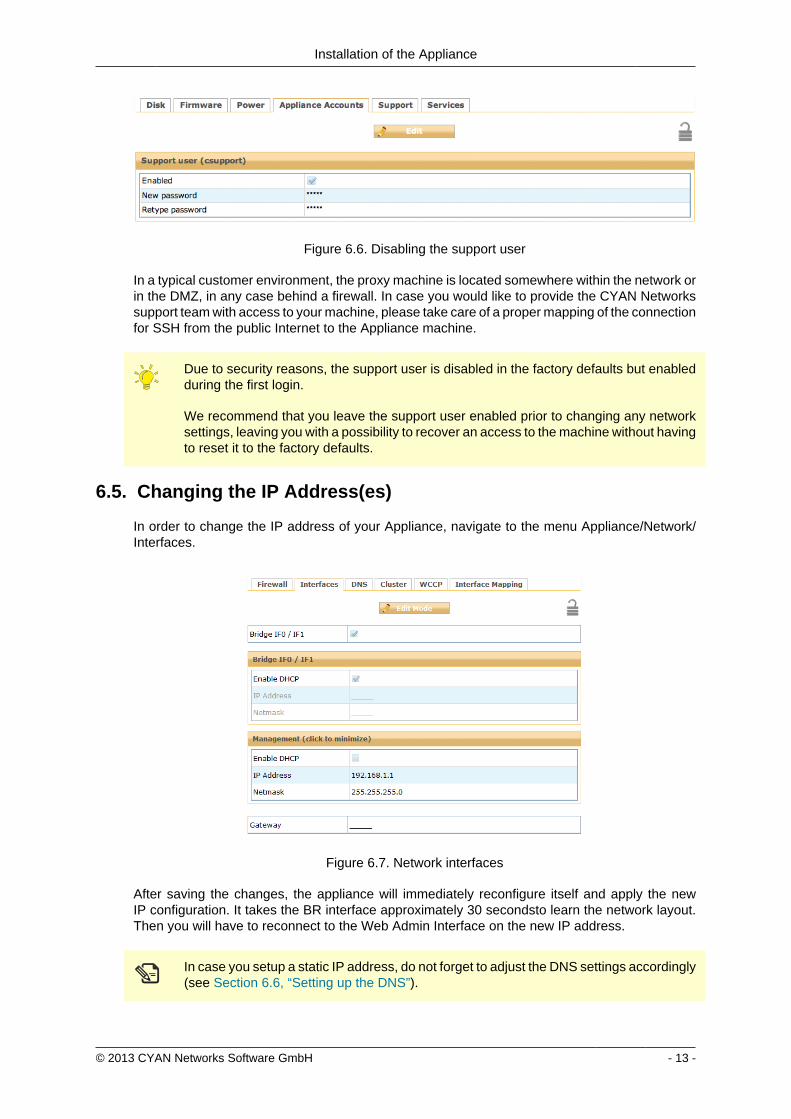
Installation of the Appliance
copy 2013 CYAN Networks Software GmbH - 15 -
The management interface does not support a gateway setting Access is enabled solelyfrom the management network segment
Make sure that you are connected via the management port of the Appliance Afterdisabling management on the proxy ports (I0 and I1) you will no longer have access tothe Web Admin Interface via this ports
copy 2013 CYAN Networks Software GmbH - 16 -
7 Configuring the Proxy ServiceCYAN Secure Web consists of a number of services that build the proxy web filtering andweb security product (Secure Web Proxy) All services and corresponding components can beconfigured via the Services menu found on the left
Figure 71 Services menu
71 Service Proxy
In most situations the Secure Web Proxy has no direct access to the Internet At least a companyfirewall is located between the proxy system and Internet access Sometimes an additionalupstream proxy needs to be used for an access
From the Secure Web Proxy access to the following resources is required for operationalpurposes Please make sure that access to these resources is allowed on any upstream firewallor proxy system
bull servicecyan-networkscom - TCP port 80 (HTTP) TCP port 443 (HTTPS)
bull appliancecyan-networkscom - TCP port 80 (HTTP)
bull debcyan-networkscom - TCP port 80 (HTTP)
In some situations the Secure Web Proxy has no direct access to the Internet and an upstreamproxy is needed for requests to CYAN update services In that case the parameters found in themenu ServicesAdminService Proxy need to be configured accordingly
Figure 72 Service Proxy
Configuring the Proxy Service
copy 2013 CYAN Networks Software GmbH - 17 -
Enable the use of an upstream proxy and specify the host and the port information in the dialogabove If the upstream proxy requires an authenticated users in order to be allowed to accessthe Internet this credentials have to be added here too
Only Basic Authentication is supported for upstream proxy access If unsure please askyour upstream proxy administrator for details on how to authenticate on the system
72 Activating the Anti-Virus Engine
The Appliance comes pre-installed with the Clam AV engine To enable virus scanning navigateto the menu ServicesProxy SettingsAnti Virus and enable the scan engine Please make surethat the selected Virus engine is set to External Scanner as shown in the screenshot below
Figure 73 Anti Virus Engine
In order for you to evaluate the ESET anti virus engine please send an e-mail tosalescyan-networkscom for a trial license
73 Testing your Installation
After you have finished configuring the Appliance donrsquot forget to press the Apply button on topof the Web Admin Interface Without this action the configuration changes are not applied to theSecure Web components
Figure 74 Apply button
Configuring the Proxy Service
copy 2013 CYAN Networks Software GmbH - 18 -
To test your installation all you need to do is to point your Internet browser to your newly setupAppliance A short guide about how to configure some of the most used browsers follows
731 Setting up browser
7311 Internet Explorer
Figure 75 Proxy setup - Internet Explorer
To configure an Internet Explorer browser to use the newly setup Appliance as a proxy servergo to menu Tools Internet Options then navigate to tab Connections and click on the buttonLAN settings In the dialog that appears check the Use proxy server for your LANhellip checkboxfill the IP address of the Appliance and port
Figure 75 ldquoProxy setup - Internet Explorerrdquo only contains a sample IP address TheIP address of your Appliance may differ Please fill in the IP in the Manual proxyconfiguration field accordingly
Configuring the Proxy Service
copy 2013 CYAN Networks Software GmbH - 19 -
7312 Mozilla Firefox
Figure 76 Proxy setup - Mozilla Firefox
To configure a Mozilla Firefox browser to use the newly setup Appliance as a proxy server go tomenu Tools Options then navigate to tab Advanced sub tab Network and in Connection boxclick on the button Settingshellip In the dialog that appears select Manual proxy configuration fill theIP address of the Appliance port and check the Use proxy for all protocols checkbox
Configuring the Proxy Service
copy 2013 CYAN Networks Software GmbH - 20 -
7313 Google Chrome
Figure 77 Proxy setup - Google Chrome
To configure a Google Chrome browser to use the newly setup Appliance as a proxy server goto menu Settings at the bottom of the page click on Show advanced settings scroll down toNetwork heading and click on the Change proxy settingshellip button The rest of the configurationis the same as for Internet Explorer browser
Configuring the Proxy Service
copy 2013 CYAN Networks Software GmbH - 21 -
7314 Opera
Figure 78 Proxy setup - Opera
To configure an Opera browser to use the newly setup Appliance as a proxy server go tomenu Settings Preferenceshellip then navigate to tab Advanced select Network in the list clickon the Proxy Servershellip button In the dialog that appears check HTTP Use this proxy for allconnections and fill the IP address of the Appliance and port
7315 Windows Domain
If you have several computer connected to a Windows Domain and you are using Internet Exploreror Google Chrome browsers the configuration of these browsers can be done also on the DomainController Let us assume the following example Windows Domain
bull One domain called ictlocal
bull One Organizational Unit (OU) within the domain called company
bull One Security Group Computers that is part of the OU company
bull Any number of computers that are placed in the Security Group Computers and on whichshould be the proxy settings be changed
To successfully set the proxy settings on all the computers within the companyComputers groupthe following steps are necessary
Configuring the Proxy Service
copy 2013 CYAN Networks Software GmbH - 22 -
First open the Group Policy Management Console Click Start click Runhellip type gpmcmscand press OK
If the Group Policy Management Console fails to start especially in the MicrosoftWindows 2003 Server you need to install it first For the Microsoft Windows 2003 Serverit can be downloaded from httpwwwmicrosoftcomen-usdownloaddetailsaspxid=21895
In the Group Policy Management Console add a new Group Policy Object (GPO) Navigate toGroup Policy Objects right click in the Contents tab and select New as showed in the followingfigure
Figure 79 Adding a new GPO
Input new name for the GPO (for example Set proxy) Now right click the newly createdGPO select Edithellip and navigate to User Configuration Windows Settings Internet ExplorerMaintenance Double click in the list on Proxy Settings and add the IP address of the Applianceas showed in the Figure 710 ldquoSetting the proxy IP addressrdquo
Figure 710 Setting the proxy IP address
Configuring the Proxy Service
copy 2013 CYAN Networks Software GmbH - 23 -
Now it is necessary to link the Set proxy GPO to the desired OU (in this example OU company)It can be done simply by dragging the GPO and dropping it on the desired OU The other way isright clicking the OU in the list selecting Link an Existing GPOhellip and selecting the Set proxyGPO from the list The following figure shows the desired result
Figure 711 Configuring the GPO
By default the GPO is restricted to all objects present in the Authenticated Users group Thisgroup should cover all the objects (Users Computers etc) that can successfully connect to thedomain To limit the GPO just to a group of selected computers (in this example grouped in theSecurity Group Computers) in the GPO view tab Scope click on the Addhellip button and selectthe appropriate Security Group You can also remove the Authenticated Users group with theRemove button
Please note that depending on the Active Directory settings it may take up to 20 minutesto see the changes on the targeted computers and a re-login may be required after thistime To speed up the changes it may help to issue command gpupdate force on thetargeted computers (but it is not required)
732 Testing access
Now enter some URL (for example httpwwwcnncom) into the address bar and press Enter toload the web page If everything works correctly you will be served a blocking page because inthe default profile defaultrestrictive all categories are blocked
Configuring the Proxy Service
copy 2013 CYAN Networks Software GmbH - 24 -
Figure 712 Category blocking page
Since Soft Use Policy is enabled in the defaultrestrictive profile you may now click on click hereto access the page regardless of the profile settings denying it
To test the Anti Virus engine direct your browser to httpwwweicarorgdownloadeicarcom andacknowledge the Soft Use Policy that will allow you to download the content even though Archiveis not an allowed Application Type in the defaultrestrictive profile This link contains harmlesstesting code that was designed specifically for testing reactions of anti-virus engines There is noneed to be concerned that you will access a page with an actual virus on it
Figure 713 AV blocking of eicarcom download
Configuring the Proxy Service
copy 2013 CYAN Networks Software GmbH - 25 -
After the virus scanning will take place and if the scanning is successful the download will bedenied from the Anti Virus engine
Only integrated anti virus engines like ESET and Avira are capable of returning thevirus name
For performance reasons we strongly recommend you usage of the integrated Anti Virusengine
In case of any troubles please refer to the troubleshoot section of this document (see Appendix ATroubleshooting) or contact support at supportcyan-networkscom for help
copy 2013 CYAN Networks Software GmbH - 26 -
8 Initial Configuration
81 Initial Authentication Setup
Secure Web is installed on the Appliance with a default configuration This configuration includesfor the purpose of authentication an IP List instance named ldquoIP Listrdquo with one IP list namedldquoglobalrdquo representing ldquothe worldrdquo (00000) You can access this default instance by navigatinginto the menu ServicesAuthenticationInstances double clicking the IP list instance in the listand navigating to the IP List tab (as shown in the following figure)
Figure 81 IP Instance default configuration
According to the order of evaluation as defined in Section 83 ldquoInitial Profile Assignment Setuprdquothe IP List instance is evaluated first Consequently the global IP list which matches any IPaddress will affect all requests
82 Initial Profile Setup
Complementary to the default authentication configuration there is also a default setup of accessrules The profile tree shows the top level profile named organization and a sibling calleddefaultrestrictive
Figure 82 Profile default configuration
As shown in the Figure 82 ldquoProfile default configurationrdquo the defaultrestrictive profile appliesa rather strict type of Internet access by blocking all categories that are available in the CYANNetworks URL database
The following figure shows the General dialog found at Services Authentication Settingsincluding the setting for the default profile which gets applied to all connections without a dedicatedprofile assignment In this case it is the default defaultrestrictive profile
Initial Configuration
copy 2013 CYAN Networks Software GmbH - 27 -
Figure 83 Default profile used
83 Initial Profile Assignment Setup
Per default all requests served through the Secure Web Proxy are restricted by thedefaultrestrictive profile as set up in the General dialog found in Service Authentication Settings(see Section 82 ldquoInitial Profile Setuprdquo)
To assign profiles to different users groups or IPs in the network the administrator has to set upauthentication and assign profiles to the user objects
The following figure shows an example setup of an IP List authentication instance andassignments based on the IP objects It can be created in the menu Service Authentication Instances
Figure 84 Example IP List instance
In this example four IP objects are created based on the layout of the IP network A network forservers and QA machines is created and two single IP objects represent workstations
Initial Configuration
copy 2013 CYAN Networks Software GmbH - 28 -
In the following figure the server and QA networks are assigned to the defaultrestrictive profileThis profile is rather restrictive and blocks all categories per default This assignment can be donein the menu Services Profile Assignment
Figure 85 Example IP profile assignments
The two workstations in this example setup are assigned to the organisation profile which isa very relaxed setup as this profile allows any request made to the Secure Web Proxy Profileassignment can be modified by selecting some Authentication Instance from the list and usingappropriate action from the context menu New profile can be assigned by selecting Assign oneprofile existing profile assignment can be removed by selecting Remove profiles from selecteditem(s) More advanced manipulation can be done in Assign profiles with time rangeshellip
After finishing all desired changes do not forget to save them all using the Save button and thento apply them using the Apply button in the top right corner of the page
copy 2013 CYAN Networks Software GmbH - 29 -
9 Updating Upgrading the ApplianceIn order to get the latest product version of your CYAN Appliance go to the menu Appliances Maintenance Firmware
To start the update you have to press the Upgrade button as shown on the following figure
Figure 91 Firmware upgrade screen
After pressing the Upgrade button you will be taken to a different screen where you can performthe actual update of your Appliance (see Figure 92 ldquoUpgrade Service screen - upgraderdquo)
Pressing the Upgrade button will start an update procedure that includes completeshutdown of all services running on the Appliance This means any proxy functionalitywill unavailable until restart of the Appliance is performed
Again press the Upgrade button You will be informed about the ongoing update in the boxbellow the button In the example screen no update was neccessary and no new packages weredownloaded
Figure 92 Upgrade Service screen - upgrade
After the update is finished you are advised to restart your Appliance This can be performed byclicking the Restart button that appears below the information box (see the following figure)
Figure 93 Upgrade Service screen - upgrade
Updating Upgrading the Appliance
copy 2013 CYAN Networks Software GmbH - 30 -
When the restart of the Appliance is completed you can navigate back to the Web Admin Interfaceusing the browser navigation button
There is no need to perform periodic checks if updates are available Information aboutavailable updates of the Appliance can be found in the CYAN Networks newsletter It isnecessary to register in the company web pages to subscribe to it Please visit httpwwwcyan-networkscomindexphpenmy-cyan to register (registration is for free)
copy 2013 CYAN Networks Software GmbH - 31 -
10 Starting the Reporting SystemThe initial configuration of the appliance includes a pre-configured but yet inactive ReportingSystem The following actions need to be completed to activate the Reporting System
1 Setting up the Reporting Database
2 Enabling the Log Feed Service
It is strongly recommended to install the reporting database on a separate system Thisespecially applies for cluster setups where a local database setup is highly discouragedA local database system can cause performance impacts when reports are calculatedand is not synchronised in cluster environments
101 Login to the Reporting System
Point your browser to the address assigned via DHCP or the management IP as the case maybe Replace ltappliance-ipgt in the following URL with the real IP address of your Appliance
httpsltappliance-ipgt9992 (for example https 192168119992)
The welcome screen allows you to either access the Secure Web Web Admin Interface or theReporting System
Figure 101 Welcome screen
Click on Login next to CYAN Reporting System to navigate to the Web Admin Interface of theReporting System
The Reporting System uses different login credentials than the Secure Web You may want toassign a different password to the Secure Web login in order restrict the administration of themachine parameters and the reporting to different people
The default login values after setup are
bull User admin
Starting the Reporting System
copy 2013 CYAN Networks Software GmbH - 32 -
bull Password admin
We strongly recommended to change the administrator password as soon as possibleNavigate to the menu Users User and double-click on the admin user or click on theperson-shaped icon next to your login name in the top right corner of the screen to changethe password
102 Setting up the Reporting Database
Figure 102 Setup the reporting database
If you have not setup any database access previously at login you will be informed aboutincorrect values (as seen in figure Figure 102 ldquoSetup the reporting databaserdquo) There are manydifferent database engines supported for using the Reporting System
bull PostgreSQL 80 or higher
bull Microsoft SQL Server 2005 or higher
bull MySQL 50 or higher
bull Oracle
bull DB2
bull H2 Database
For each database engine there is available a short quide what SQL commands to issue tocorrectly make the initial database setup You can test the settings using the Test button
The configuration of the Reporting System database assumes you already have setupa database engine of your choice and you can connect to it If after filling in allrequired information a connection error still appears please check all the login credentialpriviledges firewall settings and whether the database engine daemon is running
Whenever any new version of the Reporting System should require any changes to the databaseyour explicit confirmation is requested in order to proceed with the upgrade That will be mostlikely your case since there is no database structure yet and it needs to be created An exampleof such upgrade request shows the following figure
Starting the Reporting System
copy 2013 CYAN Networks Software GmbH - 33 -
Figure 103 Upgrade of the reporting database
Database upgrades may take a long time and can cause significant impact on theoperation and performance of the system Therefore the Reporting System will neverupgrade the database automatically but leave this decision to the administrator
After a successful completion of the setup upgrade of the database a Login button appearsat the end of the page and allows you to go to the login screen
103 Enabling the Log-Feeder
In order to activate the import of the reporting information into the reporting database the logfeeder service of Secure Web must be enabled This service picks up the log files generated bySecure Web and feeds them into the reporting database
Change to the Secure Web administrative interface select the menu Services Logging Reporting Log and browse to the dialog Log Feeder as shown in the following screenshot
Figure 104 Log feeder
The default values in this dialog are prepared to operate with the Reporting System on the samemachine In case you want to run the Reporting System on a separate machine please refer tothe Secure Web Reference Guide that describes the necessary steps
Do not forget to save any changes you have made by the Save button and then apply them usingthe Apply button
The first time you enable the Log-Feeder it may time some time to generate output from all theavailable logs
copy 2013 CYAN Networks Software GmbH - 34 -
Appendix A Troubleshooting
A1 Getting access to the command line
A11 Access via SSH
The Appliance can be accessed using SSH protocol This access is enabled by the factorydefaults During the initial setup is created a special user account in the Appliances system withusername csupport and the same password as the one used for Super Administrator accountin the Web Admin Interface (in the following text denoted as Password) For connecting to theAppliance via SSH you also need to know the Appliances IP address (for example 19216811in the following text denoted as ltappliance-ipgt)
A111 From UnixLinux
Accessing the Appliance from a Unix based system is fairly easy In the command line issue thefollowing command
ssh csupportltappliance-ipgt
If this is the first time you are connecting to the Appliance via SSH from current system confirmthe security warning and input the Password when asked to
A112 From Microsoft Windows
Accessing the Appliance via SSH from a Windows system is a little more complicated Windowssystems do not have by default installed any SHH client programm so you will need to obtainone One of the most popular ones is a freeware software called PuTTY which does not requireany installation All versions are available for download from the following web page
httpwwwchiarkgreenendorguk~sgtathamputtydownloadhtml
A direct link to the latest executable 32bit version for Windows is following
httptheearthli~sgtathamputtylatestx86puttyexe
When the download is complete run the downloaded executable and the SSH client login screenshould appear (as you can see in Figure A1 ldquoPuTTY windowrdquo) In the window input logininformation in the Host Name (or IP address) field Use the same format (substitute the exampleIP address 19216811 with the real IP address of your Appliance) Then click on the Open buttonconfirm a security warning if it appears and input the Password when asked for one
Troubleshooting
copy 2013 CYAN Networks Software GmbH - 35 -
Figure A1 PuTTY window
Once you are logged in to the system you will be able to see a simple text menu providing quickaccess to some of the useful maintenance functions
Figure A2 Console main menu
Troubleshooting
copy 2013 CYAN Networks Software GmbH - 36 -
A12 Access using monitor and keyboard
With a keyboard and a monitor attached to your appliance machine you may login to thecommand line using the credentials of the csupport user (as described in the previous section)
After logging in to the system you will be able to see and operate the same way as shown inthe previous section
A2 Recover from an invalid IP address
In case that you have set up an IP address which is not reachable by your client PC there is analternative way to change the IP address of the appliance by using the command line interface(see Section A1 ldquoGetting access to the command linerdquo)
If you have already successfully logged into the system using the csupport account navigateto menu Network management Display interfaces to see the list of available interfaces on theAppliance Make a note of the name of the interface which IP address you want to change
Figure A3 Network interfaces
Press any key to return to the previous menu and this time choose Temporarily change networkconfiguration menu item You will be asked for a name of the interface you have noted down inthe previous step new IP address network mask and optionally gateway IP address
If you are connected to the appliance via SSH and you changed the IP address of theinterface to which you are currently connected the connection will be dropped withoutany warning and you will have to reconnect to the newly set up IP address
After changing the IP address of the Appliances port via console menu you haveto change the IP address again in the Web Admin Interface Please refer to theSection 65 ldquoChanging the IP Address(es)rdquo to get information about changing the IPaddress permanently Any changes done using the console menu will last just until areboot of the Appliance
copy 2013 CYAN Networks Software GmbH - 37 -
Appendix B Contact data
B1 How to contact our sales department
Tel +43 (1) 33933-0
Email salescyan-networkscom
B2 How to contact our support department
Tel +43 (1) 33933-333
Email supportcyan-networkscom
B21 Getting Support
In case you should have any technical problems or questions and would like to get support fromour team we kindly ask you to provide us with the following information
bull Description of your question or problem
bull The version information of the product
bull The version information of Secure Web can be found after logging into the Web AdminInterface in the top part of the screen
Figure B1 Version information of the Secure Web
bull The version information of the Reporting System can be found after login in the top part ofthe screen of the Web Admin Interface
Figure B2 Version information of the Reporting System
bull All the information contained in the screen found in menu Services Services Overview
bull In the case authentication is activated provide us with the method in place (via Windows Agentvia Linux Agent etc)
bull The deployment method of the Appliance (Out-of-line In-Line DMZ)
bull The operation mode of the Appliance (dedicated mode transparent mode)
Contact data
copy 2013 CYAN Networks Software GmbH - 38 -
bull Information about the environment (proxy cascades that are used firewalls and gatewaysinvolved in the infrastructure that are of relevance to the Appliance)
The appliance interface provides the possibility to create a support package that includes theconfiguration and log files of the system This package can help us to track down the issue easierand faster Please attach this package to your e-mail
In order to create a support pack navigate to menu Appliances Maintenance Support and clickon the Download button You may select the files you want to provide to our support team andthen download a package which we kindly ask you to send to our support email address
Figure B3 Support Package
Further documentation about the product as well as technical white papers that describe certainuse cases can be found in our documentation repository on our homepage
httpwwwcyan-networkscomdocumentation
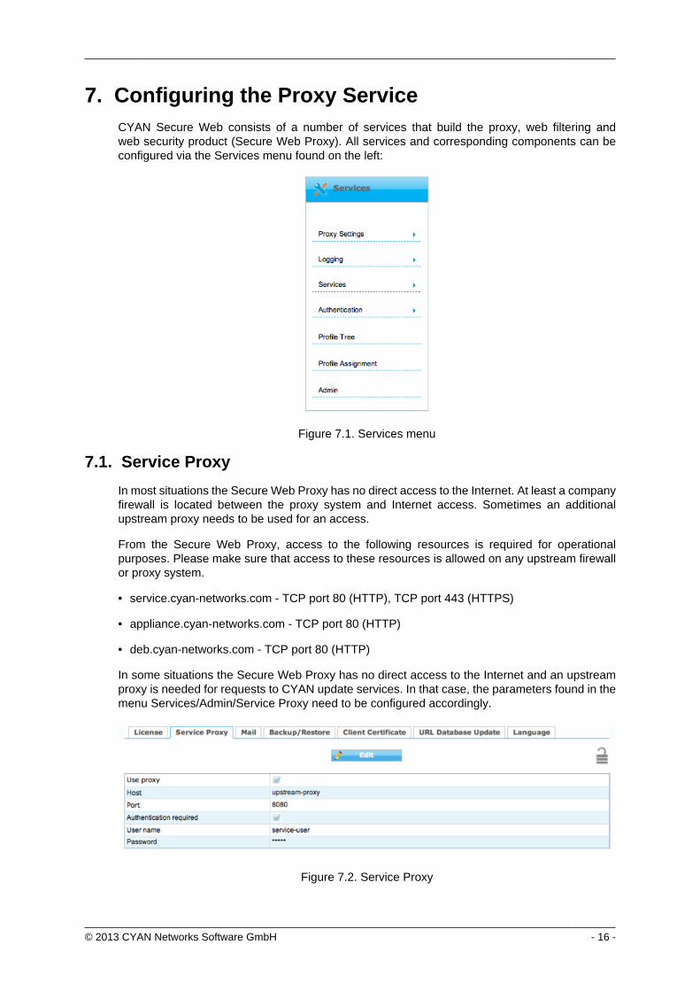

Configuring the Proxy Service
copy 2013 CYAN Networks Software GmbH - 17 -
Enable the use of an upstream proxy and specify the host and the port information in the dialogabove If the upstream proxy requires an authenticated users in order to be allowed to accessthe Internet this credentials have to be added here too
Only Basic Authentication is supported for upstream proxy access If unsure please askyour upstream proxy administrator for details on how to authenticate on the system
72 Activating the Anti-Virus Engine
The Appliance comes pre-installed with the Clam AV engine To enable virus scanning navigateto the menu ServicesProxy SettingsAnti Virus and enable the scan engine Please make surethat the selected Virus engine is set to External Scanner as shown in the screenshot below
Figure 73 Anti Virus Engine
In order for you to evaluate the ESET anti virus engine please send an e-mail tosalescyan-networkscom for a trial license
73 Testing your Installation
After you have finished configuring the Appliance donrsquot forget to press the Apply button on topof the Web Admin Interface Without this action the configuration changes are not applied to theSecure Web components
Figure 74 Apply button
Configuring the Proxy Service
copy 2013 CYAN Networks Software GmbH - 18 -
To test your installation all you need to do is to point your Internet browser to your newly setupAppliance A short guide about how to configure some of the most used browsers follows
731 Setting up browser
7311 Internet Explorer
Figure 75 Proxy setup - Internet Explorer
To configure an Internet Explorer browser to use the newly setup Appliance as a proxy servergo to menu Tools Internet Options then navigate to tab Connections and click on the buttonLAN settings In the dialog that appears check the Use proxy server for your LANhellip checkboxfill the IP address of the Appliance and port
Figure 75 ldquoProxy setup - Internet Explorerrdquo only contains a sample IP address TheIP address of your Appliance may differ Please fill in the IP in the Manual proxyconfiguration field accordingly
Configuring the Proxy Service
copy 2013 CYAN Networks Software GmbH - 19 -
7312 Mozilla Firefox
Figure 76 Proxy setup - Mozilla Firefox
To configure a Mozilla Firefox browser to use the newly setup Appliance as a proxy server go tomenu Tools Options then navigate to tab Advanced sub tab Network and in Connection boxclick on the button Settingshellip In the dialog that appears select Manual proxy configuration fill theIP address of the Appliance port and check the Use proxy for all protocols checkbox
Configuring the Proxy Service
copy 2013 CYAN Networks Software GmbH - 20 -
7313 Google Chrome
Figure 77 Proxy setup - Google Chrome
To configure a Google Chrome browser to use the newly setup Appliance as a proxy server goto menu Settings at the bottom of the page click on Show advanced settings scroll down toNetwork heading and click on the Change proxy settingshellip button The rest of the configurationis the same as for Internet Explorer browser
Configuring the Proxy Service
copy 2013 CYAN Networks Software GmbH - 21 -
7314 Opera
Figure 78 Proxy setup - Opera
To configure an Opera browser to use the newly setup Appliance as a proxy server go tomenu Settings Preferenceshellip then navigate to tab Advanced select Network in the list clickon the Proxy Servershellip button In the dialog that appears check HTTP Use this proxy for allconnections and fill the IP address of the Appliance and port
7315 Windows Domain
If you have several computer connected to a Windows Domain and you are using Internet Exploreror Google Chrome browsers the configuration of these browsers can be done also on the DomainController Let us assume the following example Windows Domain
bull One domain called ictlocal
bull One Organizational Unit (OU) within the domain called company
bull One Security Group Computers that is part of the OU company
bull Any number of computers that are placed in the Security Group Computers and on whichshould be the proxy settings be changed
To successfully set the proxy settings on all the computers within the companyComputers groupthe following steps are necessary
Configuring the Proxy Service
copy 2013 CYAN Networks Software GmbH - 22 -
First open the Group Policy Management Console Click Start click Runhellip type gpmcmscand press OK
If the Group Policy Management Console fails to start especially in the MicrosoftWindows 2003 Server you need to install it first For the Microsoft Windows 2003 Serverit can be downloaded from httpwwwmicrosoftcomen-usdownloaddetailsaspxid=21895
In the Group Policy Management Console add a new Group Policy Object (GPO) Navigate toGroup Policy Objects right click in the Contents tab and select New as showed in the followingfigure
Figure 79 Adding a new GPO
Input new name for the GPO (for example Set proxy) Now right click the newly createdGPO select Edithellip and navigate to User Configuration Windows Settings Internet ExplorerMaintenance Double click in the list on Proxy Settings and add the IP address of the Applianceas showed in the Figure 710 ldquoSetting the proxy IP addressrdquo
Figure 710 Setting the proxy IP address
Configuring the Proxy Service
copy 2013 CYAN Networks Software GmbH - 23 -
Now it is necessary to link the Set proxy GPO to the desired OU (in this example OU company)It can be done simply by dragging the GPO and dropping it on the desired OU The other way isright clicking the OU in the list selecting Link an Existing GPOhellip and selecting the Set proxyGPO from the list The following figure shows the desired result
Figure 711 Configuring the GPO
By default the GPO is restricted to all objects present in the Authenticated Users group Thisgroup should cover all the objects (Users Computers etc) that can successfully connect to thedomain To limit the GPO just to a group of selected computers (in this example grouped in theSecurity Group Computers) in the GPO view tab Scope click on the Addhellip button and selectthe appropriate Security Group You can also remove the Authenticated Users group with theRemove button
Please note that depending on the Active Directory settings it may take up to 20 minutesto see the changes on the targeted computers and a re-login may be required after thistime To speed up the changes it may help to issue command gpupdate force on thetargeted computers (but it is not required)
732 Testing access
Now enter some URL (for example httpwwwcnncom) into the address bar and press Enter toload the web page If everything works correctly you will be served a blocking page because inthe default profile defaultrestrictive all categories are blocked
Configuring the Proxy Service
copy 2013 CYAN Networks Software GmbH - 24 -
Figure 712 Category blocking page
Since Soft Use Policy is enabled in the defaultrestrictive profile you may now click on click hereto access the page regardless of the profile settings denying it
To test the Anti Virus engine direct your browser to httpwwweicarorgdownloadeicarcom andacknowledge the Soft Use Policy that will allow you to download the content even though Archiveis not an allowed Application Type in the defaultrestrictive profile This link contains harmlesstesting code that was designed specifically for testing reactions of anti-virus engines There is noneed to be concerned that you will access a page with an actual virus on it
Figure 713 AV blocking of eicarcom download
Configuring the Proxy Service
copy 2013 CYAN Networks Software GmbH - 25 -
After the virus scanning will take place and if the scanning is successful the download will bedenied from the Anti Virus engine
Only integrated anti virus engines like ESET and Avira are capable of returning thevirus name
For performance reasons we strongly recommend you usage of the integrated Anti Virusengine
In case of any troubles please refer to the troubleshoot section of this document (see Appendix ATroubleshooting) or contact support at supportcyan-networkscom for help
copy 2013 CYAN Networks Software GmbH - 26 -
8 Initial Configuration
81 Initial Authentication Setup
Secure Web is installed on the Appliance with a default configuration This configuration includesfor the purpose of authentication an IP List instance named ldquoIP Listrdquo with one IP list namedldquoglobalrdquo representing ldquothe worldrdquo (00000) You can access this default instance by navigatinginto the menu ServicesAuthenticationInstances double clicking the IP list instance in the listand navigating to the IP List tab (as shown in the following figure)
Figure 81 IP Instance default configuration
According to the order of evaluation as defined in Section 83 ldquoInitial Profile Assignment Setuprdquothe IP List instance is evaluated first Consequently the global IP list which matches any IPaddress will affect all requests
82 Initial Profile Setup
Complementary to the default authentication configuration there is also a default setup of accessrules The profile tree shows the top level profile named organization and a sibling calleddefaultrestrictive
Figure 82 Profile default configuration
As shown in the Figure 82 ldquoProfile default configurationrdquo the defaultrestrictive profile appliesa rather strict type of Internet access by blocking all categories that are available in the CYANNetworks URL database
The following figure shows the General dialog found at Services Authentication Settingsincluding the setting for the default profile which gets applied to all connections without a dedicatedprofile assignment In this case it is the default defaultrestrictive profile
Initial Configuration
copy 2013 CYAN Networks Software GmbH - 27 -
Figure 83 Default profile used
83 Initial Profile Assignment Setup
Per default all requests served through the Secure Web Proxy are restricted by thedefaultrestrictive profile as set up in the General dialog found in Service Authentication Settings(see Section 82 ldquoInitial Profile Setuprdquo)
To assign profiles to different users groups or IPs in the network the administrator has to set upauthentication and assign profiles to the user objects
The following figure shows an example setup of an IP List authentication instance andassignments based on the IP objects It can be created in the menu Service Authentication Instances
Figure 84 Example IP List instance
In this example four IP objects are created based on the layout of the IP network A network forservers and QA machines is created and two single IP objects represent workstations
Initial Configuration
copy 2013 CYAN Networks Software GmbH - 28 -
In the following figure the server and QA networks are assigned to the defaultrestrictive profileThis profile is rather restrictive and blocks all categories per default This assignment can be donein the menu Services Profile Assignment
Figure 85 Example IP profile assignments
The two workstations in this example setup are assigned to the organisation profile which isa very relaxed setup as this profile allows any request made to the Secure Web Proxy Profileassignment can be modified by selecting some Authentication Instance from the list and usingappropriate action from the context menu New profile can be assigned by selecting Assign oneprofile existing profile assignment can be removed by selecting Remove profiles from selecteditem(s) More advanced manipulation can be done in Assign profiles with time rangeshellip
After finishing all desired changes do not forget to save them all using the Save button and thento apply them using the Apply button in the top right corner of the page
copy 2013 CYAN Networks Software GmbH - 29 -
9 Updating Upgrading the ApplianceIn order to get the latest product version of your CYAN Appliance go to the menu Appliances Maintenance Firmware
To start the update you have to press the Upgrade button as shown on the following figure
Figure 91 Firmware upgrade screen
After pressing the Upgrade button you will be taken to a different screen where you can performthe actual update of your Appliance (see Figure 92 ldquoUpgrade Service screen - upgraderdquo)
Pressing the Upgrade button will start an update procedure that includes completeshutdown of all services running on the Appliance This means any proxy functionalitywill unavailable until restart of the Appliance is performed
Again press the Upgrade button You will be informed about the ongoing update in the boxbellow the button In the example screen no update was neccessary and no new packages weredownloaded
Figure 92 Upgrade Service screen - upgrade
After the update is finished you are advised to restart your Appliance This can be performed byclicking the Restart button that appears below the information box (see the following figure)
Figure 93 Upgrade Service screen - upgrade
Updating Upgrading the Appliance
copy 2013 CYAN Networks Software GmbH - 30 -
When the restart of the Appliance is completed you can navigate back to the Web Admin Interfaceusing the browser navigation button
There is no need to perform periodic checks if updates are available Information aboutavailable updates of the Appliance can be found in the CYAN Networks newsletter It isnecessary to register in the company web pages to subscribe to it Please visit httpwwwcyan-networkscomindexphpenmy-cyan to register (registration is for free)
copy 2013 CYAN Networks Software GmbH - 31 -
10 Starting the Reporting SystemThe initial configuration of the appliance includes a pre-configured but yet inactive ReportingSystem The following actions need to be completed to activate the Reporting System
1 Setting up the Reporting Database
2 Enabling the Log Feed Service
It is strongly recommended to install the reporting database on a separate system Thisespecially applies for cluster setups where a local database setup is highly discouragedA local database system can cause performance impacts when reports are calculatedand is not synchronised in cluster environments
101 Login to the Reporting System
Point your browser to the address assigned via DHCP or the management IP as the case maybe Replace ltappliance-ipgt in the following URL with the real IP address of your Appliance
httpsltappliance-ipgt9992 (for example https 192168119992)
The welcome screen allows you to either access the Secure Web Web Admin Interface or theReporting System
Figure 101 Welcome screen
Click on Login next to CYAN Reporting System to navigate to the Web Admin Interface of theReporting System
The Reporting System uses different login credentials than the Secure Web You may want toassign a different password to the Secure Web login in order restrict the administration of themachine parameters and the reporting to different people
The default login values after setup are
bull User admin
Starting the Reporting System
copy 2013 CYAN Networks Software GmbH - 32 -
bull Password admin
We strongly recommended to change the administrator password as soon as possibleNavigate to the menu Users User and double-click on the admin user or click on theperson-shaped icon next to your login name in the top right corner of the screen to changethe password
102 Setting up the Reporting Database
Figure 102 Setup the reporting database
If you have not setup any database access previously at login you will be informed aboutincorrect values (as seen in figure Figure 102 ldquoSetup the reporting databaserdquo) There are manydifferent database engines supported for using the Reporting System
bull PostgreSQL 80 or higher
bull Microsoft SQL Server 2005 or higher
bull MySQL 50 or higher
bull Oracle
bull DB2
bull H2 Database
For each database engine there is available a short quide what SQL commands to issue tocorrectly make the initial database setup You can test the settings using the Test button
The configuration of the Reporting System database assumes you already have setupa database engine of your choice and you can connect to it If after filling in allrequired information a connection error still appears please check all the login credentialpriviledges firewall settings and whether the database engine daemon is running
Whenever any new version of the Reporting System should require any changes to the databaseyour explicit confirmation is requested in order to proceed with the upgrade That will be mostlikely your case since there is no database structure yet and it needs to be created An exampleof such upgrade request shows the following figure
Starting the Reporting System
copy 2013 CYAN Networks Software GmbH - 33 -
Figure 103 Upgrade of the reporting database
Database upgrades may take a long time and can cause significant impact on theoperation and performance of the system Therefore the Reporting System will neverupgrade the database automatically but leave this decision to the administrator
After a successful completion of the setup upgrade of the database a Login button appearsat the end of the page and allows you to go to the login screen
103 Enabling the Log-Feeder
In order to activate the import of the reporting information into the reporting database the logfeeder service of Secure Web must be enabled This service picks up the log files generated bySecure Web and feeds them into the reporting database
Change to the Secure Web administrative interface select the menu Services Logging Reporting Log and browse to the dialog Log Feeder as shown in the following screenshot
Figure 104 Log feeder
The default values in this dialog are prepared to operate with the Reporting System on the samemachine In case you want to run the Reporting System on a separate machine please refer tothe Secure Web Reference Guide that describes the necessary steps
Do not forget to save any changes you have made by the Save button and then apply them usingthe Apply button
The first time you enable the Log-Feeder it may time some time to generate output from all theavailable logs
copy 2013 CYAN Networks Software GmbH - 34 -
Appendix A Troubleshooting
A1 Getting access to the command line
A11 Access via SSH
The Appliance can be accessed using SSH protocol This access is enabled by the factorydefaults During the initial setup is created a special user account in the Appliances system withusername csupport and the same password as the one used for Super Administrator accountin the Web Admin Interface (in the following text denoted as Password) For connecting to theAppliance via SSH you also need to know the Appliances IP address (for example 19216811in the following text denoted as ltappliance-ipgt)
A111 From UnixLinux
Accessing the Appliance from a Unix based system is fairly easy In the command line issue thefollowing command
ssh csupportltappliance-ipgt
If this is the first time you are connecting to the Appliance via SSH from current system confirmthe security warning and input the Password when asked to
A112 From Microsoft Windows
Accessing the Appliance via SSH from a Windows system is a little more complicated Windowssystems do not have by default installed any SHH client programm so you will need to obtainone One of the most popular ones is a freeware software called PuTTY which does not requireany installation All versions are available for download from the following web page
httpwwwchiarkgreenendorguk~sgtathamputtydownloadhtml
A direct link to the latest executable 32bit version for Windows is following
httptheearthli~sgtathamputtylatestx86puttyexe
When the download is complete run the downloaded executable and the SSH client login screenshould appear (as you can see in Figure A1 ldquoPuTTY windowrdquo) In the window input logininformation in the Host Name (or IP address) field Use the same format (substitute the exampleIP address 19216811 with the real IP address of your Appliance) Then click on the Open buttonconfirm a security warning if it appears and input the Password when asked for one
Troubleshooting
copy 2013 CYAN Networks Software GmbH - 35 -
Figure A1 PuTTY window
Once you are logged in to the system you will be able to see a simple text menu providing quickaccess to some of the useful maintenance functions
Figure A2 Console main menu
Troubleshooting
copy 2013 CYAN Networks Software GmbH - 36 -
A12 Access using monitor and keyboard
With a keyboard and a monitor attached to your appliance machine you may login to thecommand line using the credentials of the csupport user (as described in the previous section)
After logging in to the system you will be able to see and operate the same way as shown inthe previous section
A2 Recover from an invalid IP address
In case that you have set up an IP address which is not reachable by your client PC there is analternative way to change the IP address of the appliance by using the command line interface(see Section A1 ldquoGetting access to the command linerdquo)
If you have already successfully logged into the system using the csupport account navigateto menu Network management Display interfaces to see the list of available interfaces on theAppliance Make a note of the name of the interface which IP address you want to change
Figure A3 Network interfaces
Press any key to return to the previous menu and this time choose Temporarily change networkconfiguration menu item You will be asked for a name of the interface you have noted down inthe previous step new IP address network mask and optionally gateway IP address
If you are connected to the appliance via SSH and you changed the IP address of theinterface to which you are currently connected the connection will be dropped withoutany warning and you will have to reconnect to the newly set up IP address
After changing the IP address of the Appliances port via console menu you haveto change the IP address again in the Web Admin Interface Please refer to theSection 65 ldquoChanging the IP Address(es)rdquo to get information about changing the IPaddress permanently Any changes done using the console menu will last just until areboot of the Appliance
copy 2013 CYAN Networks Software GmbH - 37 -
Appendix B Contact data
B1 How to contact our sales department
Tel +43 (1) 33933-0
Email salescyan-networkscom
B2 How to contact our support department
Tel +43 (1) 33933-333
Email supportcyan-networkscom
B21 Getting Support
In case you should have any technical problems or questions and would like to get support fromour team we kindly ask you to provide us with the following information
bull Description of your question or problem
bull The version information of the product
bull The version information of Secure Web can be found after logging into the Web AdminInterface in the top part of the screen
Figure B1 Version information of the Secure Web
bull The version information of the Reporting System can be found after login in the top part ofthe screen of the Web Admin Interface
Figure B2 Version information of the Reporting System
bull All the information contained in the screen found in menu Services Services Overview
bull In the case authentication is activated provide us with the method in place (via Windows Agentvia Linux Agent etc)
bull The deployment method of the Appliance (Out-of-line In-Line DMZ)
bull The operation mode of the Appliance (dedicated mode transparent mode)
Contact data
copy 2013 CYAN Networks Software GmbH - 38 -
bull Information about the environment (proxy cascades that are used firewalls and gatewaysinvolved in the infrastructure that are of relevance to the Appliance)
The appliance interface provides the possibility to create a support package that includes theconfiguration and log files of the system This package can help us to track down the issue easierand faster Please attach this package to your e-mail
In order to create a support pack navigate to menu Appliances Maintenance Support and clickon the Download button You may select the files you want to provide to our support team andthen download a package which we kindly ask you to send to our support email address
Figure B3 Support Package
Further documentation about the product as well as technical white papers that describe certainuse cases can be found in our documentation repository on our homepage
httpwwwcyan-networkscomdocumentation
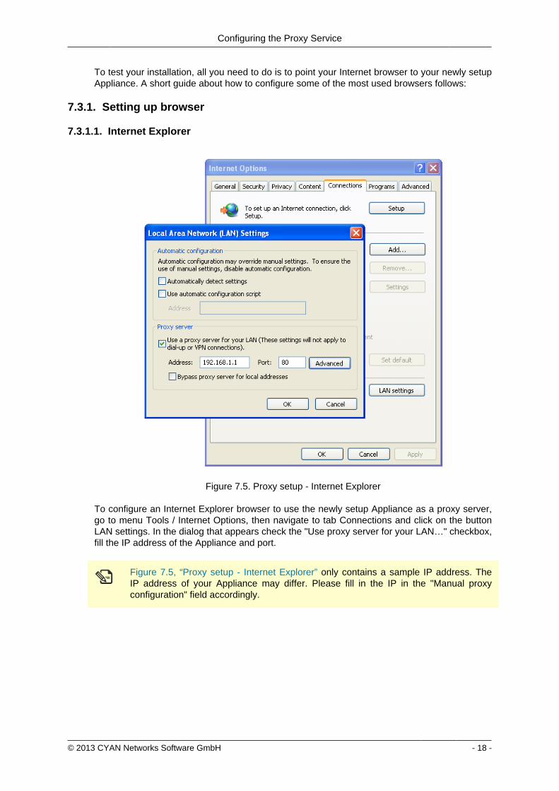
Configuring the Proxy Service
copy 2013 CYAN Networks Software GmbH - 18 -
To test your installation all you need to do is to point your Internet browser to your newly setupAppliance A short guide about how to configure some of the most used browsers follows
731 Setting up browser
7311 Internet Explorer
Figure 75 Proxy setup - Internet Explorer
To configure an Internet Explorer browser to use the newly setup Appliance as a proxy servergo to menu Tools Internet Options then navigate to tab Connections and click on the buttonLAN settings In the dialog that appears check the Use proxy server for your LANhellip checkboxfill the IP address of the Appliance and port
Figure 75 ldquoProxy setup - Internet Explorerrdquo only contains a sample IP address TheIP address of your Appliance may differ Please fill in the IP in the Manual proxyconfiguration field accordingly
Configuring the Proxy Service
copy 2013 CYAN Networks Software GmbH - 19 -
7312 Mozilla Firefox
Figure 76 Proxy setup - Mozilla Firefox
To configure a Mozilla Firefox browser to use the newly setup Appliance as a proxy server go tomenu Tools Options then navigate to tab Advanced sub tab Network and in Connection boxclick on the button Settingshellip In the dialog that appears select Manual proxy configuration fill theIP address of the Appliance port and check the Use proxy for all protocols checkbox
Configuring the Proxy Service
copy 2013 CYAN Networks Software GmbH - 20 -
7313 Google Chrome
Figure 77 Proxy setup - Google Chrome
To configure a Google Chrome browser to use the newly setup Appliance as a proxy server goto menu Settings at the bottom of the page click on Show advanced settings scroll down toNetwork heading and click on the Change proxy settingshellip button The rest of the configurationis the same as for Internet Explorer browser
Configuring the Proxy Service
copy 2013 CYAN Networks Software GmbH - 21 -
7314 Opera
Figure 78 Proxy setup - Opera
To configure an Opera browser to use the newly setup Appliance as a proxy server go tomenu Settings Preferenceshellip then navigate to tab Advanced select Network in the list clickon the Proxy Servershellip button In the dialog that appears check HTTP Use this proxy for allconnections and fill the IP address of the Appliance and port
7315 Windows Domain
If you have several computer connected to a Windows Domain and you are using Internet Exploreror Google Chrome browsers the configuration of these browsers can be done also on the DomainController Let us assume the following example Windows Domain
bull One domain called ictlocal
bull One Organizational Unit (OU) within the domain called company
bull One Security Group Computers that is part of the OU company
bull Any number of computers that are placed in the Security Group Computers and on whichshould be the proxy settings be changed
To successfully set the proxy settings on all the computers within the companyComputers groupthe following steps are necessary
Configuring the Proxy Service
copy 2013 CYAN Networks Software GmbH - 22 -
First open the Group Policy Management Console Click Start click Runhellip type gpmcmscand press OK
If the Group Policy Management Console fails to start especially in the MicrosoftWindows 2003 Server you need to install it first For the Microsoft Windows 2003 Serverit can be downloaded from httpwwwmicrosoftcomen-usdownloaddetailsaspxid=21895
In the Group Policy Management Console add a new Group Policy Object (GPO) Navigate toGroup Policy Objects right click in the Contents tab and select New as showed in the followingfigure
Figure 79 Adding a new GPO
Input new name for the GPO (for example Set proxy) Now right click the newly createdGPO select Edithellip and navigate to User Configuration Windows Settings Internet ExplorerMaintenance Double click in the list on Proxy Settings and add the IP address of the Applianceas showed in the Figure 710 ldquoSetting the proxy IP addressrdquo
Figure 710 Setting the proxy IP address
Configuring the Proxy Service
copy 2013 CYAN Networks Software GmbH - 23 -
Now it is necessary to link the Set proxy GPO to the desired OU (in this example OU company)It can be done simply by dragging the GPO and dropping it on the desired OU The other way isright clicking the OU in the list selecting Link an Existing GPOhellip and selecting the Set proxyGPO from the list The following figure shows the desired result
Figure 711 Configuring the GPO
By default the GPO is restricted to all objects present in the Authenticated Users group Thisgroup should cover all the objects (Users Computers etc) that can successfully connect to thedomain To limit the GPO just to a group of selected computers (in this example grouped in theSecurity Group Computers) in the GPO view tab Scope click on the Addhellip button and selectthe appropriate Security Group You can also remove the Authenticated Users group with theRemove button
Please note that depending on the Active Directory settings it may take up to 20 minutesto see the changes on the targeted computers and a re-login may be required after thistime To speed up the changes it may help to issue command gpupdate force on thetargeted computers (but it is not required)
732 Testing access
Now enter some URL (for example httpwwwcnncom) into the address bar and press Enter toload the web page If everything works correctly you will be served a blocking page because inthe default profile defaultrestrictive all categories are blocked
Configuring the Proxy Service
copy 2013 CYAN Networks Software GmbH - 24 -
Figure 712 Category blocking page
Since Soft Use Policy is enabled in the defaultrestrictive profile you may now click on click hereto access the page regardless of the profile settings denying it
To test the Anti Virus engine direct your browser to httpwwweicarorgdownloadeicarcom andacknowledge the Soft Use Policy that will allow you to download the content even though Archiveis not an allowed Application Type in the defaultrestrictive profile This link contains harmlesstesting code that was designed specifically for testing reactions of anti-virus engines There is noneed to be concerned that you will access a page with an actual virus on it
Figure 713 AV blocking of eicarcom download
Configuring the Proxy Service
copy 2013 CYAN Networks Software GmbH - 25 -
After the virus scanning will take place and if the scanning is successful the download will bedenied from the Anti Virus engine
Only integrated anti virus engines like ESET and Avira are capable of returning thevirus name
For performance reasons we strongly recommend you usage of the integrated Anti Virusengine
In case of any troubles please refer to the troubleshoot section of this document (see Appendix ATroubleshooting) or contact support at supportcyan-networkscom for help
copy 2013 CYAN Networks Software GmbH - 26 -
8 Initial Configuration
81 Initial Authentication Setup
Secure Web is installed on the Appliance with a default configuration This configuration includesfor the purpose of authentication an IP List instance named ldquoIP Listrdquo with one IP list namedldquoglobalrdquo representing ldquothe worldrdquo (00000) You can access this default instance by navigatinginto the menu ServicesAuthenticationInstances double clicking the IP list instance in the listand navigating to the IP List tab (as shown in the following figure)
Figure 81 IP Instance default configuration
According to the order of evaluation as defined in Section 83 ldquoInitial Profile Assignment Setuprdquothe IP List instance is evaluated first Consequently the global IP list which matches any IPaddress will affect all requests
82 Initial Profile Setup
Complementary to the default authentication configuration there is also a default setup of accessrules The profile tree shows the top level profile named organization and a sibling calleddefaultrestrictive
Figure 82 Profile default configuration
As shown in the Figure 82 ldquoProfile default configurationrdquo the defaultrestrictive profile appliesa rather strict type of Internet access by blocking all categories that are available in the CYANNetworks URL database
The following figure shows the General dialog found at Services Authentication Settingsincluding the setting for the default profile which gets applied to all connections without a dedicatedprofile assignment In this case it is the default defaultrestrictive profile
Initial Configuration
copy 2013 CYAN Networks Software GmbH - 27 -
Figure 83 Default profile used
83 Initial Profile Assignment Setup
Per default all requests served through the Secure Web Proxy are restricted by thedefaultrestrictive profile as set up in the General dialog found in Service Authentication Settings(see Section 82 ldquoInitial Profile Setuprdquo)
To assign profiles to different users groups or IPs in the network the administrator has to set upauthentication and assign profiles to the user objects
The following figure shows an example setup of an IP List authentication instance andassignments based on the IP objects It can be created in the menu Service Authentication Instances
Figure 84 Example IP List instance
In this example four IP objects are created based on the layout of the IP network A network forservers and QA machines is created and two single IP objects represent workstations
Initial Configuration
copy 2013 CYAN Networks Software GmbH - 28 -
In the following figure the server and QA networks are assigned to the defaultrestrictive profileThis profile is rather restrictive and blocks all categories per default This assignment can be donein the menu Services Profile Assignment
Figure 85 Example IP profile assignments
The two workstations in this example setup are assigned to the organisation profile which isa very relaxed setup as this profile allows any request made to the Secure Web Proxy Profileassignment can be modified by selecting some Authentication Instance from the list and usingappropriate action from the context menu New profile can be assigned by selecting Assign oneprofile existing profile assignment can be removed by selecting Remove profiles from selecteditem(s) More advanced manipulation can be done in Assign profiles with time rangeshellip
After finishing all desired changes do not forget to save them all using the Save button and thento apply them using the Apply button in the top right corner of the page
copy 2013 CYAN Networks Software GmbH - 29 -
9 Updating Upgrading the ApplianceIn order to get the latest product version of your CYAN Appliance go to the menu Appliances Maintenance Firmware
To start the update you have to press the Upgrade button as shown on the following figure
Figure 91 Firmware upgrade screen
After pressing the Upgrade button you will be taken to a different screen where you can performthe actual update of your Appliance (see Figure 92 ldquoUpgrade Service screen - upgraderdquo)
Pressing the Upgrade button will start an update procedure that includes completeshutdown of all services running on the Appliance This means any proxy functionalitywill unavailable until restart of the Appliance is performed
Again press the Upgrade button You will be informed about the ongoing update in the boxbellow the button In the example screen no update was neccessary and no new packages weredownloaded
Figure 92 Upgrade Service screen - upgrade
After the update is finished you are advised to restart your Appliance This can be performed byclicking the Restart button that appears below the information box (see the following figure)
Figure 93 Upgrade Service screen - upgrade
Updating Upgrading the Appliance
copy 2013 CYAN Networks Software GmbH - 30 -
When the restart of the Appliance is completed you can navigate back to the Web Admin Interfaceusing the browser navigation button
There is no need to perform periodic checks if updates are available Information aboutavailable updates of the Appliance can be found in the CYAN Networks newsletter It isnecessary to register in the company web pages to subscribe to it Please visit httpwwwcyan-networkscomindexphpenmy-cyan to register (registration is for free)
copy 2013 CYAN Networks Software GmbH - 31 -
10 Starting the Reporting SystemThe initial configuration of the appliance includes a pre-configured but yet inactive ReportingSystem The following actions need to be completed to activate the Reporting System
1 Setting up the Reporting Database
2 Enabling the Log Feed Service
It is strongly recommended to install the reporting database on a separate system Thisespecially applies for cluster setups where a local database setup is highly discouragedA local database system can cause performance impacts when reports are calculatedand is not synchronised in cluster environments
101 Login to the Reporting System
Point your browser to the address assigned via DHCP or the management IP as the case maybe Replace ltappliance-ipgt in the following URL with the real IP address of your Appliance
httpsltappliance-ipgt9992 (for example https 192168119992)
The welcome screen allows you to either access the Secure Web Web Admin Interface or theReporting System
Figure 101 Welcome screen
Click on Login next to CYAN Reporting System to navigate to the Web Admin Interface of theReporting System
The Reporting System uses different login credentials than the Secure Web You may want toassign a different password to the Secure Web login in order restrict the administration of themachine parameters and the reporting to different people
The default login values after setup are
bull User admin
Starting the Reporting System
copy 2013 CYAN Networks Software GmbH - 32 -
bull Password admin
We strongly recommended to change the administrator password as soon as possibleNavigate to the menu Users User and double-click on the admin user or click on theperson-shaped icon next to your login name in the top right corner of the screen to changethe password
102 Setting up the Reporting Database
Figure 102 Setup the reporting database
If you have not setup any database access previously at login you will be informed aboutincorrect values (as seen in figure Figure 102 ldquoSetup the reporting databaserdquo) There are manydifferent database engines supported for using the Reporting System
bull PostgreSQL 80 or higher
bull Microsoft SQL Server 2005 or higher
bull MySQL 50 or higher
bull Oracle
bull DB2
bull H2 Database
For each database engine there is available a short quide what SQL commands to issue tocorrectly make the initial database setup You can test the settings using the Test button
The configuration of the Reporting System database assumes you already have setupa database engine of your choice and you can connect to it If after filling in allrequired information a connection error still appears please check all the login credentialpriviledges firewall settings and whether the database engine daemon is running
Whenever any new version of the Reporting System should require any changes to the databaseyour explicit confirmation is requested in order to proceed with the upgrade That will be mostlikely your case since there is no database structure yet and it needs to be created An exampleof such upgrade request shows the following figure
Starting the Reporting System
copy 2013 CYAN Networks Software GmbH - 33 -
Figure 103 Upgrade of the reporting database
Database upgrades may take a long time and can cause significant impact on theoperation and performance of the system Therefore the Reporting System will neverupgrade the database automatically but leave this decision to the administrator
After a successful completion of the setup upgrade of the database a Login button appearsat the end of the page and allows you to go to the login screen
103 Enabling the Log-Feeder
In order to activate the import of the reporting information into the reporting database the logfeeder service of Secure Web must be enabled This service picks up the log files generated bySecure Web and feeds them into the reporting database
Change to the Secure Web administrative interface select the menu Services Logging Reporting Log and browse to the dialog Log Feeder as shown in the following screenshot
Figure 104 Log feeder
The default values in this dialog are prepared to operate with the Reporting System on the samemachine In case you want to run the Reporting System on a separate machine please refer tothe Secure Web Reference Guide that describes the necessary steps
Do not forget to save any changes you have made by the Save button and then apply them usingthe Apply button
The first time you enable the Log-Feeder it may time some time to generate output from all theavailable logs
copy 2013 CYAN Networks Software GmbH - 34 -
Appendix A Troubleshooting
A1 Getting access to the command line
A11 Access via SSH
The Appliance can be accessed using SSH protocol This access is enabled by the factorydefaults During the initial setup is created a special user account in the Appliances system withusername csupport and the same password as the one used for Super Administrator accountin the Web Admin Interface (in the following text denoted as Password) For connecting to theAppliance via SSH you also need to know the Appliances IP address (for example 19216811in the following text denoted as ltappliance-ipgt)
A111 From UnixLinux
Accessing the Appliance from a Unix based system is fairly easy In the command line issue thefollowing command
ssh csupportltappliance-ipgt
If this is the first time you are connecting to the Appliance via SSH from current system confirmthe security warning and input the Password when asked to
A112 From Microsoft Windows
Accessing the Appliance via SSH from a Windows system is a little more complicated Windowssystems do not have by default installed any SHH client programm so you will need to obtainone One of the most popular ones is a freeware software called PuTTY which does not requireany installation All versions are available for download from the following web page
httpwwwchiarkgreenendorguk~sgtathamputtydownloadhtml
A direct link to the latest executable 32bit version for Windows is following
httptheearthli~sgtathamputtylatestx86puttyexe
When the download is complete run the downloaded executable and the SSH client login screenshould appear (as you can see in Figure A1 ldquoPuTTY windowrdquo) In the window input logininformation in the Host Name (or IP address) field Use the same format (substitute the exampleIP address 19216811 with the real IP address of your Appliance) Then click on the Open buttonconfirm a security warning if it appears and input the Password when asked for one
Troubleshooting
copy 2013 CYAN Networks Software GmbH - 35 -
Figure A1 PuTTY window
Once you are logged in to the system you will be able to see a simple text menu providing quickaccess to some of the useful maintenance functions
Figure A2 Console main menu
Troubleshooting
copy 2013 CYAN Networks Software GmbH - 36 -
A12 Access using monitor and keyboard
With a keyboard and a monitor attached to your appliance machine you may login to thecommand line using the credentials of the csupport user (as described in the previous section)
After logging in to the system you will be able to see and operate the same way as shown inthe previous section
A2 Recover from an invalid IP address
In case that you have set up an IP address which is not reachable by your client PC there is analternative way to change the IP address of the appliance by using the command line interface(see Section A1 ldquoGetting access to the command linerdquo)
If you have already successfully logged into the system using the csupport account navigateto menu Network management Display interfaces to see the list of available interfaces on theAppliance Make a note of the name of the interface which IP address you want to change
Figure A3 Network interfaces
Press any key to return to the previous menu and this time choose Temporarily change networkconfiguration menu item You will be asked for a name of the interface you have noted down inthe previous step new IP address network mask and optionally gateway IP address
If you are connected to the appliance via SSH and you changed the IP address of theinterface to which you are currently connected the connection will be dropped withoutany warning and you will have to reconnect to the newly set up IP address
After changing the IP address of the Appliances port via console menu you haveto change the IP address again in the Web Admin Interface Please refer to theSection 65 ldquoChanging the IP Address(es)rdquo to get information about changing the IPaddress permanently Any changes done using the console menu will last just until areboot of the Appliance
copy 2013 CYAN Networks Software GmbH - 37 -
Appendix B Contact data
B1 How to contact our sales department
Tel +43 (1) 33933-0
Email salescyan-networkscom
B2 How to contact our support department
Tel +43 (1) 33933-333
Email supportcyan-networkscom
B21 Getting Support
In case you should have any technical problems or questions and would like to get support fromour team we kindly ask you to provide us with the following information
bull Description of your question or problem
bull The version information of the product
bull The version information of Secure Web can be found after logging into the Web AdminInterface in the top part of the screen
Figure B1 Version information of the Secure Web
bull The version information of the Reporting System can be found after login in the top part ofthe screen of the Web Admin Interface
Figure B2 Version information of the Reporting System
bull All the information contained in the screen found in menu Services Services Overview
bull In the case authentication is activated provide us with the method in place (via Windows Agentvia Linux Agent etc)
bull The deployment method of the Appliance (Out-of-line In-Line DMZ)
bull The operation mode of the Appliance (dedicated mode transparent mode)
Contact data
copy 2013 CYAN Networks Software GmbH - 38 -
bull Information about the environment (proxy cascades that are used firewalls and gatewaysinvolved in the infrastructure that are of relevance to the Appliance)
The appliance interface provides the possibility to create a support package that includes theconfiguration and log files of the system This package can help us to track down the issue easierand faster Please attach this package to your e-mail
In order to create a support pack navigate to menu Appliances Maintenance Support and clickon the Download button You may select the files you want to provide to our support team andthen download a package which we kindly ask you to send to our support email address
Figure B3 Support Package
Further documentation about the product as well as technical white papers that describe certainuse cases can be found in our documentation repository on our homepage
httpwwwcyan-networkscomdocumentation
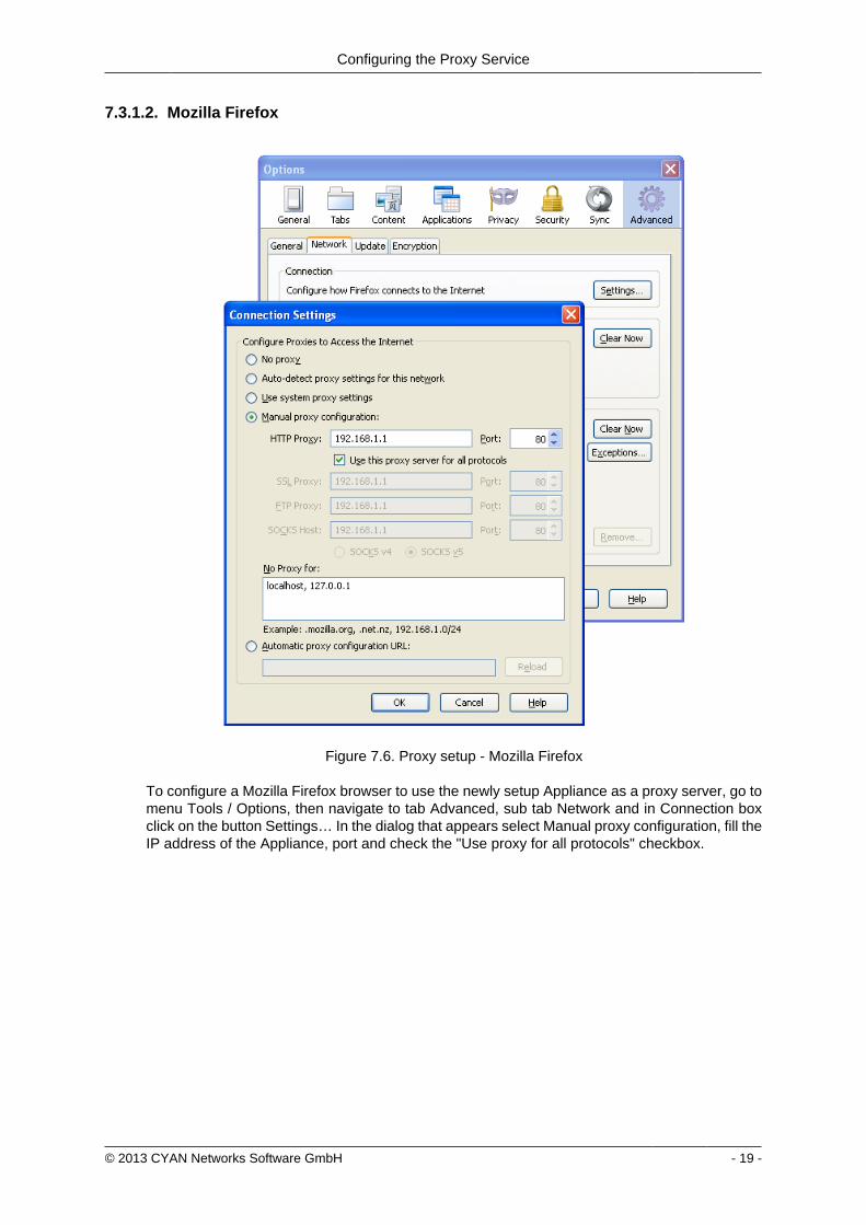
Configuring the Proxy Service
copy 2013 CYAN Networks Software GmbH - 20 -
7313 Google Chrome
Figure 77 Proxy setup - Google Chrome
To configure a Google Chrome browser to use the newly setup Appliance as a proxy server goto menu Settings at the bottom of the page click on Show advanced settings scroll down toNetwork heading and click on the Change proxy settingshellip button The rest of the configurationis the same as for Internet Explorer browser
Configuring the Proxy Service
copy 2013 CYAN Networks Software GmbH - 21 -
7314 Opera
Figure 78 Proxy setup - Opera
To configure an Opera browser to use the newly setup Appliance as a proxy server go tomenu Settings Preferenceshellip then navigate to tab Advanced select Network in the list clickon the Proxy Servershellip button In the dialog that appears check HTTP Use this proxy for allconnections and fill the IP address of the Appliance and port
7315 Windows Domain
If you have several computer connected to a Windows Domain and you are using Internet Exploreror Google Chrome browsers the configuration of these browsers can be done also on the DomainController Let us assume the following example Windows Domain
bull One domain called ictlocal
bull One Organizational Unit (OU) within the domain called company
bull One Security Group Computers that is part of the OU company
bull Any number of computers that are placed in the Security Group Computers and on whichshould be the proxy settings be changed
To successfully set the proxy settings on all the computers within the companyComputers groupthe following steps are necessary
Configuring the Proxy Service
copy 2013 CYAN Networks Software GmbH - 22 -
First open the Group Policy Management Console Click Start click Runhellip type gpmcmscand press OK
If the Group Policy Management Console fails to start especially in the MicrosoftWindows 2003 Server you need to install it first For the Microsoft Windows 2003 Serverit can be downloaded from httpwwwmicrosoftcomen-usdownloaddetailsaspxid=21895
In the Group Policy Management Console add a new Group Policy Object (GPO) Navigate toGroup Policy Objects right click in the Contents tab and select New as showed in the followingfigure
Figure 79 Adding a new GPO
Input new name for the GPO (for example Set proxy) Now right click the newly createdGPO select Edithellip and navigate to User Configuration Windows Settings Internet ExplorerMaintenance Double click in the list on Proxy Settings and add the IP address of the Applianceas showed in the Figure 710 ldquoSetting the proxy IP addressrdquo
Figure 710 Setting the proxy IP address
Configuring the Proxy Service
copy 2013 CYAN Networks Software GmbH - 23 -
Now it is necessary to link the Set proxy GPO to the desired OU (in this example OU company)It can be done simply by dragging the GPO and dropping it on the desired OU The other way isright clicking the OU in the list selecting Link an Existing GPOhellip and selecting the Set proxyGPO from the list The following figure shows the desired result
Figure 711 Configuring the GPO
By default the GPO is restricted to all objects present in the Authenticated Users group Thisgroup should cover all the objects (Users Computers etc) that can successfully connect to thedomain To limit the GPO just to a group of selected computers (in this example grouped in theSecurity Group Computers) in the GPO view tab Scope click on the Addhellip button and selectthe appropriate Security Group You can also remove the Authenticated Users group with theRemove button
Please note that depending on the Active Directory settings it may take up to 20 minutesto see the changes on the targeted computers and a re-login may be required after thistime To speed up the changes it may help to issue command gpupdate force on thetargeted computers (but it is not required)
732 Testing access
Now enter some URL (for example httpwwwcnncom) into the address bar and press Enter toload the web page If everything works correctly you will be served a blocking page because inthe default profile defaultrestrictive all categories are blocked
Configuring the Proxy Service
copy 2013 CYAN Networks Software GmbH - 24 -
Figure 712 Category blocking page
Since Soft Use Policy is enabled in the defaultrestrictive profile you may now click on click hereto access the page regardless of the profile settings denying it
To test the Anti Virus engine direct your browser to httpwwweicarorgdownloadeicarcom andacknowledge the Soft Use Policy that will allow you to download the content even though Archiveis not an allowed Application Type in the defaultrestrictive profile This link contains harmlesstesting code that was designed specifically for testing reactions of anti-virus engines There is noneed to be concerned that you will access a page with an actual virus on it
Figure 713 AV blocking of eicarcom download
Configuring the Proxy Service
copy 2013 CYAN Networks Software GmbH - 25 -
After the virus scanning will take place and if the scanning is successful the download will bedenied from the Anti Virus engine
Only integrated anti virus engines like ESET and Avira are capable of returning thevirus name
For performance reasons we strongly recommend you usage of the integrated Anti Virusengine
In case of any troubles please refer to the troubleshoot section of this document (see Appendix ATroubleshooting) or contact support at supportcyan-networkscom for help
copy 2013 CYAN Networks Software GmbH - 26 -
8 Initial Configuration
81 Initial Authentication Setup
Secure Web is installed on the Appliance with a default configuration This configuration includesfor the purpose of authentication an IP List instance named ldquoIP Listrdquo with one IP list namedldquoglobalrdquo representing ldquothe worldrdquo (00000) You can access this default instance by navigatinginto the menu ServicesAuthenticationInstances double clicking the IP list instance in the listand navigating to the IP List tab (as shown in the following figure)
Figure 81 IP Instance default configuration
According to the order of evaluation as defined in Section 83 ldquoInitial Profile Assignment Setuprdquothe IP List instance is evaluated first Consequently the global IP list which matches any IPaddress will affect all requests
82 Initial Profile Setup
Complementary to the default authentication configuration there is also a default setup of accessrules The profile tree shows the top level profile named organization and a sibling calleddefaultrestrictive
Figure 82 Profile default configuration
As shown in the Figure 82 ldquoProfile default configurationrdquo the defaultrestrictive profile appliesa rather strict type of Internet access by blocking all categories that are available in the CYANNetworks URL database
The following figure shows the General dialog found at Services Authentication Settingsincluding the setting for the default profile which gets applied to all connections without a dedicatedprofile assignment In this case it is the default defaultrestrictive profile
Initial Configuration
copy 2013 CYAN Networks Software GmbH - 27 -
Figure 83 Default profile used
83 Initial Profile Assignment Setup
Per default all requests served through the Secure Web Proxy are restricted by thedefaultrestrictive profile as set up in the General dialog found in Service Authentication Settings(see Section 82 ldquoInitial Profile Setuprdquo)
To assign profiles to different users groups or IPs in the network the administrator has to set upauthentication and assign profiles to the user objects
The following figure shows an example setup of an IP List authentication instance andassignments based on the IP objects It can be created in the menu Service Authentication Instances
Figure 84 Example IP List instance
In this example four IP objects are created based on the layout of the IP network A network forservers and QA machines is created and two single IP objects represent workstations
Initial Configuration
copy 2013 CYAN Networks Software GmbH - 28 -
In the following figure the server and QA networks are assigned to the defaultrestrictive profileThis profile is rather restrictive and blocks all categories per default This assignment can be donein the menu Services Profile Assignment
Figure 85 Example IP profile assignments
The two workstations in this example setup are assigned to the organisation profile which isa very relaxed setup as this profile allows any request made to the Secure Web Proxy Profileassignment can be modified by selecting some Authentication Instance from the list and usingappropriate action from the context menu New profile can be assigned by selecting Assign oneprofile existing profile assignment can be removed by selecting Remove profiles from selecteditem(s) More advanced manipulation can be done in Assign profiles with time rangeshellip
After finishing all desired changes do not forget to save them all using the Save button and thento apply them using the Apply button in the top right corner of the page
copy 2013 CYAN Networks Software GmbH - 29 -
9 Updating Upgrading the ApplianceIn order to get the latest product version of your CYAN Appliance go to the menu Appliances Maintenance Firmware
To start the update you have to press the Upgrade button as shown on the following figure
Figure 91 Firmware upgrade screen
After pressing the Upgrade button you will be taken to a different screen where you can performthe actual update of your Appliance (see Figure 92 ldquoUpgrade Service screen - upgraderdquo)
Pressing the Upgrade button will start an update procedure that includes completeshutdown of all services running on the Appliance This means any proxy functionalitywill unavailable until restart of the Appliance is performed
Again press the Upgrade button You will be informed about the ongoing update in the boxbellow the button In the example screen no update was neccessary and no new packages weredownloaded
Figure 92 Upgrade Service screen - upgrade
After the update is finished you are advised to restart your Appliance This can be performed byclicking the Restart button that appears below the information box (see the following figure)
Figure 93 Upgrade Service screen - upgrade
Updating Upgrading the Appliance
copy 2013 CYAN Networks Software GmbH - 30 -
When the restart of the Appliance is completed you can navigate back to the Web Admin Interfaceusing the browser navigation button
There is no need to perform periodic checks if updates are available Information aboutavailable updates of the Appliance can be found in the CYAN Networks newsletter It isnecessary to register in the company web pages to subscribe to it Please visit httpwwwcyan-networkscomindexphpenmy-cyan to register (registration is for free)
copy 2013 CYAN Networks Software GmbH - 31 -
10 Starting the Reporting SystemThe initial configuration of the appliance includes a pre-configured but yet inactive ReportingSystem The following actions need to be completed to activate the Reporting System
1 Setting up the Reporting Database
2 Enabling the Log Feed Service
It is strongly recommended to install the reporting database on a separate system Thisespecially applies for cluster setups where a local database setup is highly discouragedA local database system can cause performance impacts when reports are calculatedand is not synchronised in cluster environments
101 Login to the Reporting System
Point your browser to the address assigned via DHCP or the management IP as the case maybe Replace ltappliance-ipgt in the following URL with the real IP address of your Appliance
httpsltappliance-ipgt9992 (for example https 192168119992)
The welcome screen allows you to either access the Secure Web Web Admin Interface or theReporting System
Figure 101 Welcome screen
Click on Login next to CYAN Reporting System to navigate to the Web Admin Interface of theReporting System
The Reporting System uses different login credentials than the Secure Web You may want toassign a different password to the Secure Web login in order restrict the administration of themachine parameters and the reporting to different people
The default login values after setup are
bull User admin
Starting the Reporting System
copy 2013 CYAN Networks Software GmbH - 32 -
bull Password admin
We strongly recommended to change the administrator password as soon as possibleNavigate to the menu Users User and double-click on the admin user or click on theperson-shaped icon next to your login name in the top right corner of the screen to changethe password
102 Setting up the Reporting Database
Figure 102 Setup the reporting database
If you have not setup any database access previously at login you will be informed aboutincorrect values (as seen in figure Figure 102 ldquoSetup the reporting databaserdquo) There are manydifferent database engines supported for using the Reporting System
bull PostgreSQL 80 or higher
bull Microsoft SQL Server 2005 or higher
bull MySQL 50 or higher
bull Oracle
bull DB2
bull H2 Database
For each database engine there is available a short quide what SQL commands to issue tocorrectly make the initial database setup You can test the settings using the Test button
The configuration of the Reporting System database assumes you already have setupa database engine of your choice and you can connect to it If after filling in allrequired information a connection error still appears please check all the login credentialpriviledges firewall settings and whether the database engine daemon is running
Whenever any new version of the Reporting System should require any changes to the databaseyour explicit confirmation is requested in order to proceed with the upgrade That will be mostlikely your case since there is no database structure yet and it needs to be created An exampleof such upgrade request shows the following figure
Starting the Reporting System
copy 2013 CYAN Networks Software GmbH - 33 -
Figure 103 Upgrade of the reporting database
Database upgrades may take a long time and can cause significant impact on theoperation and performance of the system Therefore the Reporting System will neverupgrade the database automatically but leave this decision to the administrator
After a successful completion of the setup upgrade of the database a Login button appearsat the end of the page and allows you to go to the login screen
103 Enabling the Log-Feeder
In order to activate the import of the reporting information into the reporting database the logfeeder service of Secure Web must be enabled This service picks up the log files generated bySecure Web and feeds them into the reporting database
Change to the Secure Web administrative interface select the menu Services Logging Reporting Log and browse to the dialog Log Feeder as shown in the following screenshot
Figure 104 Log feeder
The default values in this dialog are prepared to operate with the Reporting System on the samemachine In case you want to run the Reporting System on a separate machine please refer tothe Secure Web Reference Guide that describes the necessary steps
Do not forget to save any changes you have made by the Save button and then apply them usingthe Apply button
The first time you enable the Log-Feeder it may time some time to generate output from all theavailable logs
copy 2013 CYAN Networks Software GmbH - 34 -
Appendix A Troubleshooting
A1 Getting access to the command line
A11 Access via SSH
The Appliance can be accessed using SSH protocol This access is enabled by the factorydefaults During the initial setup is created a special user account in the Appliances system withusername csupport and the same password as the one used for Super Administrator accountin the Web Admin Interface (in the following text denoted as Password) For connecting to theAppliance via SSH you also need to know the Appliances IP address (for example 19216811in the following text denoted as ltappliance-ipgt)
A111 From UnixLinux
Accessing the Appliance from a Unix based system is fairly easy In the command line issue thefollowing command
ssh csupportltappliance-ipgt
If this is the first time you are connecting to the Appliance via SSH from current system confirmthe security warning and input the Password when asked to
A112 From Microsoft Windows
Accessing the Appliance via SSH from a Windows system is a little more complicated Windowssystems do not have by default installed any SHH client programm so you will need to obtainone One of the most popular ones is a freeware software called PuTTY which does not requireany installation All versions are available for download from the following web page
httpwwwchiarkgreenendorguk~sgtathamputtydownloadhtml
A direct link to the latest executable 32bit version for Windows is following
httptheearthli~sgtathamputtylatestx86puttyexe
When the download is complete run the downloaded executable and the SSH client login screenshould appear (as you can see in Figure A1 ldquoPuTTY windowrdquo) In the window input logininformation in the Host Name (or IP address) field Use the same format (substitute the exampleIP address 19216811 with the real IP address of your Appliance) Then click on the Open buttonconfirm a security warning if it appears and input the Password when asked for one
Troubleshooting
copy 2013 CYAN Networks Software GmbH - 35 -
Figure A1 PuTTY window
Once you are logged in to the system you will be able to see a simple text menu providing quickaccess to some of the useful maintenance functions
Figure A2 Console main menu
Troubleshooting
copy 2013 CYAN Networks Software GmbH - 36 -
A12 Access using monitor and keyboard
With a keyboard and a monitor attached to your appliance machine you may login to thecommand line using the credentials of the csupport user (as described in the previous section)
After logging in to the system you will be able to see and operate the same way as shown inthe previous section
A2 Recover from an invalid IP address
In case that you have set up an IP address which is not reachable by your client PC there is analternative way to change the IP address of the appliance by using the command line interface(see Section A1 ldquoGetting access to the command linerdquo)
If you have already successfully logged into the system using the csupport account navigateto menu Network management Display interfaces to see the list of available interfaces on theAppliance Make a note of the name of the interface which IP address you want to change
Figure A3 Network interfaces
Press any key to return to the previous menu and this time choose Temporarily change networkconfiguration menu item You will be asked for a name of the interface you have noted down inthe previous step new IP address network mask and optionally gateway IP address
If you are connected to the appliance via SSH and you changed the IP address of theinterface to which you are currently connected the connection will be dropped withoutany warning and you will have to reconnect to the newly set up IP address
After changing the IP address of the Appliances port via console menu you haveto change the IP address again in the Web Admin Interface Please refer to theSection 65 ldquoChanging the IP Address(es)rdquo to get information about changing the IPaddress permanently Any changes done using the console menu will last just until areboot of the Appliance
copy 2013 CYAN Networks Software GmbH - 37 -
Appendix B Contact data
B1 How to contact our sales department
Tel +43 (1) 33933-0
Email salescyan-networkscom
B2 How to contact our support department
Tel +43 (1) 33933-333
Email supportcyan-networkscom
B21 Getting Support
In case you should have any technical problems or questions and would like to get support fromour team we kindly ask you to provide us with the following information
bull Description of your question or problem
bull The version information of the product
bull The version information of Secure Web can be found after logging into the Web AdminInterface in the top part of the screen
Figure B1 Version information of the Secure Web
bull The version information of the Reporting System can be found after login in the top part ofthe screen of the Web Admin Interface
Figure B2 Version information of the Reporting System
bull All the information contained in the screen found in menu Services Services Overview
bull In the case authentication is activated provide us with the method in place (via Windows Agentvia Linux Agent etc)
bull The deployment method of the Appliance (Out-of-line In-Line DMZ)
bull The operation mode of the Appliance (dedicated mode transparent mode)
Contact data
copy 2013 CYAN Networks Software GmbH - 38 -
bull Information about the environment (proxy cascades that are used firewalls and gatewaysinvolved in the infrastructure that are of relevance to the Appliance)
The appliance interface provides the possibility to create a support package that includes theconfiguration and log files of the system This package can help us to track down the issue easierand faster Please attach this package to your e-mail
In order to create a support pack navigate to menu Appliances Maintenance Support and clickon the Download button You may select the files you want to provide to our support team andthen download a package which we kindly ask you to send to our support email address
Figure B3 Support Package
Further documentation about the product as well as technical white papers that describe certainuse cases can be found in our documentation repository on our homepage
httpwwwcyan-networkscomdocumentation
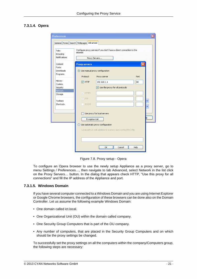
Configuring the Proxy Service
copy 2013 CYAN Networks Software GmbH - 21 -
7314 Opera
Figure 78 Proxy setup - Opera
To configure an Opera browser to use the newly setup Appliance as a proxy server go tomenu Settings Preferenceshellip then navigate to tab Advanced select Network in the list clickon the Proxy Servershellip button In the dialog that appears check HTTP Use this proxy for allconnections and fill the IP address of the Appliance and port
7315 Windows Domain
If you have several computer connected to a Windows Domain and you are using Internet Exploreror Google Chrome browsers the configuration of these browsers can be done also on the DomainController Let us assume the following example Windows Domain
bull One domain called ictlocal
bull One Organizational Unit (OU) within the domain called company
bull One Security Group Computers that is part of the OU company
bull Any number of computers that are placed in the Security Group Computers and on whichshould be the proxy settings be changed
To successfully set the proxy settings on all the computers within the companyComputers groupthe following steps are necessary
Configuring the Proxy Service
copy 2013 CYAN Networks Software GmbH - 22 -
First open the Group Policy Management Console Click Start click Runhellip type gpmcmscand press OK
If the Group Policy Management Console fails to start especially in the MicrosoftWindows 2003 Server you need to install it first For the Microsoft Windows 2003 Serverit can be downloaded from httpwwwmicrosoftcomen-usdownloaddetailsaspxid=21895
In the Group Policy Management Console add a new Group Policy Object (GPO) Navigate toGroup Policy Objects right click in the Contents tab and select New as showed in the followingfigure
Figure 79 Adding a new GPO
Input new name for the GPO (for example Set proxy) Now right click the newly createdGPO select Edithellip and navigate to User Configuration Windows Settings Internet ExplorerMaintenance Double click in the list on Proxy Settings and add the IP address of the Applianceas showed in the Figure 710 ldquoSetting the proxy IP addressrdquo
Figure 710 Setting the proxy IP address
Configuring the Proxy Service
copy 2013 CYAN Networks Software GmbH - 23 -
Now it is necessary to link the Set proxy GPO to the desired OU (in this example OU company)It can be done simply by dragging the GPO and dropping it on the desired OU The other way isright clicking the OU in the list selecting Link an Existing GPOhellip and selecting the Set proxyGPO from the list The following figure shows the desired result
Figure 711 Configuring the GPO
By default the GPO is restricted to all objects present in the Authenticated Users group Thisgroup should cover all the objects (Users Computers etc) that can successfully connect to thedomain To limit the GPO just to a group of selected computers (in this example grouped in theSecurity Group Computers) in the GPO view tab Scope click on the Addhellip button and selectthe appropriate Security Group You can also remove the Authenticated Users group with theRemove button
Please note that depending on the Active Directory settings it may take up to 20 minutesto see the changes on the targeted computers and a re-login may be required after thistime To speed up the changes it may help to issue command gpupdate force on thetargeted computers (but it is not required)
732 Testing access
Now enter some URL (for example httpwwwcnncom) into the address bar and press Enter toload the web page If everything works correctly you will be served a blocking page because inthe default profile defaultrestrictive all categories are blocked
Configuring the Proxy Service
copy 2013 CYAN Networks Software GmbH - 24 -
Figure 712 Category blocking page
Since Soft Use Policy is enabled in the defaultrestrictive profile you may now click on click hereto access the page regardless of the profile settings denying it
To test the Anti Virus engine direct your browser to httpwwweicarorgdownloadeicarcom andacknowledge the Soft Use Policy that will allow you to download the content even though Archiveis not an allowed Application Type in the defaultrestrictive profile This link contains harmlesstesting code that was designed specifically for testing reactions of anti-virus engines There is noneed to be concerned that you will access a page with an actual virus on it
Figure 713 AV blocking of eicarcom download
Configuring the Proxy Service
copy 2013 CYAN Networks Software GmbH - 25 -
After the virus scanning will take place and if the scanning is successful the download will bedenied from the Anti Virus engine
Only integrated anti virus engines like ESET and Avira are capable of returning thevirus name
For performance reasons we strongly recommend you usage of the integrated Anti Virusengine
In case of any troubles please refer to the troubleshoot section of this document (see Appendix ATroubleshooting) or contact support at supportcyan-networkscom for help
copy 2013 CYAN Networks Software GmbH - 26 -
8 Initial Configuration
81 Initial Authentication Setup
Secure Web is installed on the Appliance with a default configuration This configuration includesfor the purpose of authentication an IP List instance named ldquoIP Listrdquo with one IP list namedldquoglobalrdquo representing ldquothe worldrdquo (00000) You can access this default instance by navigatinginto the menu ServicesAuthenticationInstances double clicking the IP list instance in the listand navigating to the IP List tab (as shown in the following figure)
Figure 81 IP Instance default configuration
According to the order of evaluation as defined in Section 83 ldquoInitial Profile Assignment Setuprdquothe IP List instance is evaluated first Consequently the global IP list which matches any IPaddress will affect all requests
82 Initial Profile Setup
Complementary to the default authentication configuration there is also a default setup of accessrules The profile tree shows the top level profile named organization and a sibling calleddefaultrestrictive
Figure 82 Profile default configuration
As shown in the Figure 82 ldquoProfile default configurationrdquo the defaultrestrictive profile appliesa rather strict type of Internet access by blocking all categories that are available in the CYANNetworks URL database
The following figure shows the General dialog found at Services Authentication Settingsincluding the setting for the default profile which gets applied to all connections without a dedicatedprofile assignment In this case it is the default defaultrestrictive profile
Initial Configuration
copy 2013 CYAN Networks Software GmbH - 27 -
Figure 83 Default profile used
83 Initial Profile Assignment Setup
Per default all requests served through the Secure Web Proxy are restricted by thedefaultrestrictive profile as set up in the General dialog found in Service Authentication Settings(see Section 82 ldquoInitial Profile Setuprdquo)
To assign profiles to different users groups or IPs in the network the administrator has to set upauthentication and assign profiles to the user objects
The following figure shows an example setup of an IP List authentication instance andassignments based on the IP objects It can be created in the menu Service Authentication Instances
Figure 84 Example IP List instance
In this example four IP objects are created based on the layout of the IP network A network forservers and QA machines is created and two single IP objects represent workstations
Initial Configuration
copy 2013 CYAN Networks Software GmbH - 28 -
In the following figure the server and QA networks are assigned to the defaultrestrictive profileThis profile is rather restrictive and blocks all categories per default This assignment can be donein the menu Services Profile Assignment
Figure 85 Example IP profile assignments
The two workstations in this example setup are assigned to the organisation profile which isa very relaxed setup as this profile allows any request made to the Secure Web Proxy Profileassignment can be modified by selecting some Authentication Instance from the list and usingappropriate action from the context menu New profile can be assigned by selecting Assign oneprofile existing profile assignment can be removed by selecting Remove profiles from selecteditem(s) More advanced manipulation can be done in Assign profiles with time rangeshellip
After finishing all desired changes do not forget to save them all using the Save button and thento apply them using the Apply button in the top right corner of the page
copy 2013 CYAN Networks Software GmbH - 29 -
9 Updating Upgrading the ApplianceIn order to get the latest product version of your CYAN Appliance go to the menu Appliances Maintenance Firmware
To start the update you have to press the Upgrade button as shown on the following figure
Figure 91 Firmware upgrade screen
After pressing the Upgrade button you will be taken to a different screen where you can performthe actual update of your Appliance (see Figure 92 ldquoUpgrade Service screen - upgraderdquo)
Pressing the Upgrade button will start an update procedure that includes completeshutdown of all services running on the Appliance This means any proxy functionalitywill unavailable until restart of the Appliance is performed
Again press the Upgrade button You will be informed about the ongoing update in the boxbellow the button In the example screen no update was neccessary and no new packages weredownloaded
Figure 92 Upgrade Service screen - upgrade
After the update is finished you are advised to restart your Appliance This can be performed byclicking the Restart button that appears below the information box (see the following figure)
Figure 93 Upgrade Service screen - upgrade
Updating Upgrading the Appliance
copy 2013 CYAN Networks Software GmbH - 30 -
When the restart of the Appliance is completed you can navigate back to the Web Admin Interfaceusing the browser navigation button
There is no need to perform periodic checks if updates are available Information aboutavailable updates of the Appliance can be found in the CYAN Networks newsletter It isnecessary to register in the company web pages to subscribe to it Please visit httpwwwcyan-networkscomindexphpenmy-cyan to register (registration is for free)
copy 2013 CYAN Networks Software GmbH - 31 -
10 Starting the Reporting SystemThe initial configuration of the appliance includes a pre-configured but yet inactive ReportingSystem The following actions need to be completed to activate the Reporting System
1 Setting up the Reporting Database
2 Enabling the Log Feed Service
It is strongly recommended to install the reporting database on a separate system Thisespecially applies for cluster setups where a local database setup is highly discouragedA local database system can cause performance impacts when reports are calculatedand is not synchronised in cluster environments
101 Login to the Reporting System
Point your browser to the address assigned via DHCP or the management IP as the case maybe Replace ltappliance-ipgt in the following URL with the real IP address of your Appliance
httpsltappliance-ipgt9992 (for example https 192168119992)
The welcome screen allows you to either access the Secure Web Web Admin Interface or theReporting System
Figure 101 Welcome screen
Click on Login next to CYAN Reporting System to navigate to the Web Admin Interface of theReporting System
The Reporting System uses different login credentials than the Secure Web You may want toassign a different password to the Secure Web login in order restrict the administration of themachine parameters and the reporting to different people
The default login values after setup are
bull User admin
Starting the Reporting System
copy 2013 CYAN Networks Software GmbH - 32 -
bull Password admin
We strongly recommended to change the administrator password as soon as possibleNavigate to the menu Users User and double-click on the admin user or click on theperson-shaped icon next to your login name in the top right corner of the screen to changethe password
102 Setting up the Reporting Database
Figure 102 Setup the reporting database
If you have not setup any database access previously at login you will be informed aboutincorrect values (as seen in figure Figure 102 ldquoSetup the reporting databaserdquo) There are manydifferent database engines supported for using the Reporting System
bull PostgreSQL 80 or higher
bull Microsoft SQL Server 2005 or higher
bull MySQL 50 or higher
bull Oracle
bull DB2
bull H2 Database
For each database engine there is available a short quide what SQL commands to issue tocorrectly make the initial database setup You can test the settings using the Test button
The configuration of the Reporting System database assumes you already have setupa database engine of your choice and you can connect to it If after filling in allrequired information a connection error still appears please check all the login credentialpriviledges firewall settings and whether the database engine daemon is running
Whenever any new version of the Reporting System should require any changes to the databaseyour explicit confirmation is requested in order to proceed with the upgrade That will be mostlikely your case since there is no database structure yet and it needs to be created An exampleof such upgrade request shows the following figure
Starting the Reporting System
copy 2013 CYAN Networks Software GmbH - 33 -
Figure 103 Upgrade of the reporting database
Database upgrades may take a long time and can cause significant impact on theoperation and performance of the system Therefore the Reporting System will neverupgrade the database automatically but leave this decision to the administrator
After a successful completion of the setup upgrade of the database a Login button appearsat the end of the page and allows you to go to the login screen
103 Enabling the Log-Feeder
In order to activate the import of the reporting information into the reporting database the logfeeder service of Secure Web must be enabled This service picks up the log files generated bySecure Web and feeds them into the reporting database
Change to the Secure Web administrative interface select the menu Services Logging Reporting Log and browse to the dialog Log Feeder as shown in the following screenshot
Figure 104 Log feeder
The default values in this dialog are prepared to operate with the Reporting System on the samemachine In case you want to run the Reporting System on a separate machine please refer tothe Secure Web Reference Guide that describes the necessary steps
Do not forget to save any changes you have made by the Save button and then apply them usingthe Apply button
The first time you enable the Log-Feeder it may time some time to generate output from all theavailable logs
copy 2013 CYAN Networks Software GmbH - 34 -
Appendix A Troubleshooting
A1 Getting access to the command line
A11 Access via SSH
The Appliance can be accessed using SSH protocol This access is enabled by the factorydefaults During the initial setup is created a special user account in the Appliances system withusername csupport and the same password as the one used for Super Administrator accountin the Web Admin Interface (in the following text denoted as Password) For connecting to theAppliance via SSH you also need to know the Appliances IP address (for example 19216811in the following text denoted as ltappliance-ipgt)
A111 From UnixLinux
Accessing the Appliance from a Unix based system is fairly easy In the command line issue thefollowing command
ssh csupportltappliance-ipgt
If this is the first time you are connecting to the Appliance via SSH from current system confirmthe security warning and input the Password when asked to
A112 From Microsoft Windows
Accessing the Appliance via SSH from a Windows system is a little more complicated Windowssystems do not have by default installed any SHH client programm so you will need to obtainone One of the most popular ones is a freeware software called PuTTY which does not requireany installation All versions are available for download from the following web page
httpwwwchiarkgreenendorguk~sgtathamputtydownloadhtml
A direct link to the latest executable 32bit version for Windows is following
httptheearthli~sgtathamputtylatestx86puttyexe
When the download is complete run the downloaded executable and the SSH client login screenshould appear (as you can see in Figure A1 ldquoPuTTY windowrdquo) In the window input logininformation in the Host Name (or IP address) field Use the same format (substitute the exampleIP address 19216811 with the real IP address of your Appliance) Then click on the Open buttonconfirm a security warning if it appears and input the Password when asked for one
Troubleshooting
copy 2013 CYAN Networks Software GmbH - 35 -
Figure A1 PuTTY window
Once you are logged in to the system you will be able to see a simple text menu providing quickaccess to some of the useful maintenance functions
Figure A2 Console main menu
Troubleshooting
copy 2013 CYAN Networks Software GmbH - 36 -
A12 Access using monitor and keyboard
With a keyboard and a monitor attached to your appliance machine you may login to thecommand line using the credentials of the csupport user (as described in the previous section)
After logging in to the system you will be able to see and operate the same way as shown inthe previous section
A2 Recover from an invalid IP address
In case that you have set up an IP address which is not reachable by your client PC there is analternative way to change the IP address of the appliance by using the command line interface(see Section A1 ldquoGetting access to the command linerdquo)
If you have already successfully logged into the system using the csupport account navigateto menu Network management Display interfaces to see the list of available interfaces on theAppliance Make a note of the name of the interface which IP address you want to change
Figure A3 Network interfaces
Press any key to return to the previous menu and this time choose Temporarily change networkconfiguration menu item You will be asked for a name of the interface you have noted down inthe previous step new IP address network mask and optionally gateway IP address
If you are connected to the appliance via SSH and you changed the IP address of theinterface to which you are currently connected the connection will be dropped withoutany warning and you will have to reconnect to the newly set up IP address
After changing the IP address of the Appliances port via console menu you haveto change the IP address again in the Web Admin Interface Please refer to theSection 65 ldquoChanging the IP Address(es)rdquo to get information about changing the IPaddress permanently Any changes done using the console menu will last just until areboot of the Appliance
copy 2013 CYAN Networks Software GmbH - 37 -
Appendix B Contact data
B1 How to contact our sales department
Tel +43 (1) 33933-0
Email salescyan-networkscom
B2 How to contact our support department
Tel +43 (1) 33933-333
Email supportcyan-networkscom
B21 Getting Support
In case you should have any technical problems or questions and would like to get support fromour team we kindly ask you to provide us with the following information
bull Description of your question or problem
bull The version information of the product
bull The version information of Secure Web can be found after logging into the Web AdminInterface in the top part of the screen
Figure B1 Version information of the Secure Web
bull The version information of the Reporting System can be found after login in the top part ofthe screen of the Web Admin Interface
Figure B2 Version information of the Reporting System
bull All the information contained in the screen found in menu Services Services Overview
bull In the case authentication is activated provide us with the method in place (via Windows Agentvia Linux Agent etc)
bull The deployment method of the Appliance (Out-of-line In-Line DMZ)
bull The operation mode of the Appliance (dedicated mode transparent mode)
Contact data
copy 2013 CYAN Networks Software GmbH - 38 -
bull Information about the environment (proxy cascades that are used firewalls and gatewaysinvolved in the infrastructure that are of relevance to the Appliance)
The appliance interface provides the possibility to create a support package that includes theconfiguration and log files of the system This package can help us to track down the issue easierand faster Please attach this package to your e-mail
In order to create a support pack navigate to menu Appliances Maintenance Support and clickon the Download button You may select the files you want to provide to our support team andthen download a package which we kindly ask you to send to our support email address
Figure B3 Support Package
Further documentation about the product as well as technical white papers that describe certainuse cases can be found in our documentation repository on our homepage
httpwwwcyan-networkscomdocumentation
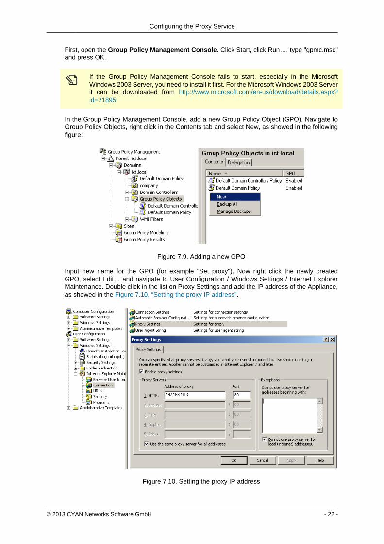
Configuring the Proxy Service
copy 2013 CYAN Networks Software GmbH - 22 -
First open the Group Policy Management Console Click Start click Runhellip type gpmcmscand press OK
If the Group Policy Management Console fails to start especially in the MicrosoftWindows 2003 Server you need to install it first For the Microsoft Windows 2003 Serverit can be downloaded from httpwwwmicrosoftcomen-usdownloaddetailsaspxid=21895
In the Group Policy Management Console add a new Group Policy Object (GPO) Navigate toGroup Policy Objects right click in the Contents tab and select New as showed in the followingfigure
Figure 79 Adding a new GPO
Input new name for the GPO (for example Set proxy) Now right click the newly createdGPO select Edithellip and navigate to User Configuration Windows Settings Internet ExplorerMaintenance Double click in the list on Proxy Settings and add the IP address of the Applianceas showed in the Figure 710 ldquoSetting the proxy IP addressrdquo
Figure 710 Setting the proxy IP address
Configuring the Proxy Service
copy 2013 CYAN Networks Software GmbH - 23 -
Now it is necessary to link the Set proxy GPO to the desired OU (in this example OU company)It can be done simply by dragging the GPO and dropping it on the desired OU The other way isright clicking the OU in the list selecting Link an Existing GPOhellip and selecting the Set proxyGPO from the list The following figure shows the desired result
Figure 711 Configuring the GPO
By default the GPO is restricted to all objects present in the Authenticated Users group Thisgroup should cover all the objects (Users Computers etc) that can successfully connect to thedomain To limit the GPO just to a group of selected computers (in this example grouped in theSecurity Group Computers) in the GPO view tab Scope click on the Addhellip button and selectthe appropriate Security Group You can also remove the Authenticated Users group with theRemove button
Please note that depending on the Active Directory settings it may take up to 20 minutesto see the changes on the targeted computers and a re-login may be required after thistime To speed up the changes it may help to issue command gpupdate force on thetargeted computers (but it is not required)
732 Testing access
Now enter some URL (for example httpwwwcnncom) into the address bar and press Enter toload the web page If everything works correctly you will be served a blocking page because inthe default profile defaultrestrictive all categories are blocked
Configuring the Proxy Service
copy 2013 CYAN Networks Software GmbH - 24 -
Figure 712 Category blocking page
Since Soft Use Policy is enabled in the defaultrestrictive profile you may now click on click hereto access the page regardless of the profile settings denying it
To test the Anti Virus engine direct your browser to httpwwweicarorgdownloadeicarcom andacknowledge the Soft Use Policy that will allow you to download the content even though Archiveis not an allowed Application Type in the defaultrestrictive profile This link contains harmlesstesting code that was designed specifically for testing reactions of anti-virus engines There is noneed to be concerned that you will access a page with an actual virus on it
Figure 713 AV blocking of eicarcom download
Configuring the Proxy Service
copy 2013 CYAN Networks Software GmbH - 25 -
After the virus scanning will take place and if the scanning is successful the download will bedenied from the Anti Virus engine
Only integrated anti virus engines like ESET and Avira are capable of returning thevirus name
For performance reasons we strongly recommend you usage of the integrated Anti Virusengine
In case of any troubles please refer to the troubleshoot section of this document (see Appendix ATroubleshooting) or contact support at supportcyan-networkscom for help
copy 2013 CYAN Networks Software GmbH - 26 -
8 Initial Configuration
81 Initial Authentication Setup
Secure Web is installed on the Appliance with a default configuration This configuration includesfor the purpose of authentication an IP List instance named ldquoIP Listrdquo with one IP list namedldquoglobalrdquo representing ldquothe worldrdquo (00000) You can access this default instance by navigatinginto the menu ServicesAuthenticationInstances double clicking the IP list instance in the listand navigating to the IP List tab (as shown in the following figure)
Figure 81 IP Instance default configuration
According to the order of evaluation as defined in Section 83 ldquoInitial Profile Assignment Setuprdquothe IP List instance is evaluated first Consequently the global IP list which matches any IPaddress will affect all requests
82 Initial Profile Setup
Complementary to the default authentication configuration there is also a default setup of accessrules The profile tree shows the top level profile named organization and a sibling calleddefaultrestrictive
Figure 82 Profile default configuration
As shown in the Figure 82 ldquoProfile default configurationrdquo the defaultrestrictive profile appliesa rather strict type of Internet access by blocking all categories that are available in the CYANNetworks URL database
The following figure shows the General dialog found at Services Authentication Settingsincluding the setting for the default profile which gets applied to all connections without a dedicatedprofile assignment In this case it is the default defaultrestrictive profile
Initial Configuration
copy 2013 CYAN Networks Software GmbH - 27 -
Figure 83 Default profile used
83 Initial Profile Assignment Setup
Per default all requests served through the Secure Web Proxy are restricted by thedefaultrestrictive profile as set up in the General dialog found in Service Authentication Settings(see Section 82 ldquoInitial Profile Setuprdquo)
To assign profiles to different users groups or IPs in the network the administrator has to set upauthentication and assign profiles to the user objects
The following figure shows an example setup of an IP List authentication instance andassignments based on the IP objects It can be created in the menu Service Authentication Instances
Figure 84 Example IP List instance
In this example four IP objects are created based on the layout of the IP network A network forservers and QA machines is created and two single IP objects represent workstations
Initial Configuration
copy 2013 CYAN Networks Software GmbH - 28 -
In the following figure the server and QA networks are assigned to the defaultrestrictive profileThis profile is rather restrictive and blocks all categories per default This assignment can be donein the menu Services Profile Assignment
Figure 85 Example IP profile assignments
The two workstations in this example setup are assigned to the organisation profile which isa very relaxed setup as this profile allows any request made to the Secure Web Proxy Profileassignment can be modified by selecting some Authentication Instance from the list and usingappropriate action from the context menu New profile can be assigned by selecting Assign oneprofile existing profile assignment can be removed by selecting Remove profiles from selecteditem(s) More advanced manipulation can be done in Assign profiles with time rangeshellip
After finishing all desired changes do not forget to save them all using the Save button and thento apply them using the Apply button in the top right corner of the page
copy 2013 CYAN Networks Software GmbH - 29 -
9 Updating Upgrading the ApplianceIn order to get the latest product version of your CYAN Appliance go to the menu Appliances Maintenance Firmware
To start the update you have to press the Upgrade button as shown on the following figure
Figure 91 Firmware upgrade screen
After pressing the Upgrade button you will be taken to a different screen where you can performthe actual update of your Appliance (see Figure 92 ldquoUpgrade Service screen - upgraderdquo)
Pressing the Upgrade button will start an update procedure that includes completeshutdown of all services running on the Appliance This means any proxy functionalitywill unavailable until restart of the Appliance is performed
Again press the Upgrade button You will be informed about the ongoing update in the boxbellow the button In the example screen no update was neccessary and no new packages weredownloaded
Figure 92 Upgrade Service screen - upgrade
After the update is finished you are advised to restart your Appliance This can be performed byclicking the Restart button that appears below the information box (see the following figure)
Figure 93 Upgrade Service screen - upgrade
Updating Upgrading the Appliance
copy 2013 CYAN Networks Software GmbH - 30 -
When the restart of the Appliance is completed you can navigate back to the Web Admin Interfaceusing the browser navigation button
There is no need to perform periodic checks if updates are available Information aboutavailable updates of the Appliance can be found in the CYAN Networks newsletter It isnecessary to register in the company web pages to subscribe to it Please visit httpwwwcyan-networkscomindexphpenmy-cyan to register (registration is for free)
copy 2013 CYAN Networks Software GmbH - 31 -
10 Starting the Reporting SystemThe initial configuration of the appliance includes a pre-configured but yet inactive ReportingSystem The following actions need to be completed to activate the Reporting System
1 Setting up the Reporting Database
2 Enabling the Log Feed Service
It is strongly recommended to install the reporting database on a separate system Thisespecially applies for cluster setups where a local database setup is highly discouragedA local database system can cause performance impacts when reports are calculatedand is not synchronised in cluster environments
101 Login to the Reporting System
Point your browser to the address assigned via DHCP or the management IP as the case maybe Replace ltappliance-ipgt in the following URL with the real IP address of your Appliance
httpsltappliance-ipgt9992 (for example https 192168119992)
The welcome screen allows you to either access the Secure Web Web Admin Interface or theReporting System
Figure 101 Welcome screen
Click on Login next to CYAN Reporting System to navigate to the Web Admin Interface of theReporting System
The Reporting System uses different login credentials than the Secure Web You may want toassign a different password to the Secure Web login in order restrict the administration of themachine parameters and the reporting to different people
The default login values after setup are
bull User admin
Starting the Reporting System
copy 2013 CYAN Networks Software GmbH - 32 -
bull Password admin
We strongly recommended to change the administrator password as soon as possibleNavigate to the menu Users User and double-click on the admin user or click on theperson-shaped icon next to your login name in the top right corner of the screen to changethe password
102 Setting up the Reporting Database
Figure 102 Setup the reporting database
If you have not setup any database access previously at login you will be informed aboutincorrect values (as seen in figure Figure 102 ldquoSetup the reporting databaserdquo) There are manydifferent database engines supported for using the Reporting System
bull PostgreSQL 80 or higher
bull Microsoft SQL Server 2005 or higher
bull MySQL 50 or higher
bull Oracle
bull DB2
bull H2 Database
For each database engine there is available a short quide what SQL commands to issue tocorrectly make the initial database setup You can test the settings using the Test button
The configuration of the Reporting System database assumes you already have setupa database engine of your choice and you can connect to it If after filling in allrequired information a connection error still appears please check all the login credentialpriviledges firewall settings and whether the database engine daemon is running
Whenever any new version of the Reporting System should require any changes to the databaseyour explicit confirmation is requested in order to proceed with the upgrade That will be mostlikely your case since there is no database structure yet and it needs to be created An exampleof such upgrade request shows the following figure
Starting the Reporting System
copy 2013 CYAN Networks Software GmbH - 33 -
Figure 103 Upgrade of the reporting database
Database upgrades may take a long time and can cause significant impact on theoperation and performance of the system Therefore the Reporting System will neverupgrade the database automatically but leave this decision to the administrator
After a successful completion of the setup upgrade of the database a Login button appearsat the end of the page and allows you to go to the login screen
103 Enabling the Log-Feeder
In order to activate the import of the reporting information into the reporting database the logfeeder service of Secure Web must be enabled This service picks up the log files generated bySecure Web and feeds them into the reporting database
Change to the Secure Web administrative interface select the menu Services Logging Reporting Log and browse to the dialog Log Feeder as shown in the following screenshot
Figure 104 Log feeder
The default values in this dialog are prepared to operate with the Reporting System on the samemachine In case you want to run the Reporting System on a separate machine please refer tothe Secure Web Reference Guide that describes the necessary steps
Do not forget to save any changes you have made by the Save button and then apply them usingthe Apply button
The first time you enable the Log-Feeder it may time some time to generate output from all theavailable logs
copy 2013 CYAN Networks Software GmbH - 34 -
Appendix A Troubleshooting
A1 Getting access to the command line
A11 Access via SSH
The Appliance can be accessed using SSH protocol This access is enabled by the factorydefaults During the initial setup is created a special user account in the Appliances system withusername csupport and the same password as the one used for Super Administrator accountin the Web Admin Interface (in the following text denoted as Password) For connecting to theAppliance via SSH you also need to know the Appliances IP address (for example 19216811in the following text denoted as ltappliance-ipgt)
A111 From UnixLinux
Accessing the Appliance from a Unix based system is fairly easy In the command line issue thefollowing command
ssh csupportltappliance-ipgt
If this is the first time you are connecting to the Appliance via SSH from current system confirmthe security warning and input the Password when asked to
A112 From Microsoft Windows
Accessing the Appliance via SSH from a Windows system is a little more complicated Windowssystems do not have by default installed any SHH client programm so you will need to obtainone One of the most popular ones is a freeware software called PuTTY which does not requireany installation All versions are available for download from the following web page
httpwwwchiarkgreenendorguk~sgtathamputtydownloadhtml
A direct link to the latest executable 32bit version for Windows is following
httptheearthli~sgtathamputtylatestx86puttyexe
When the download is complete run the downloaded executable and the SSH client login screenshould appear (as you can see in Figure A1 ldquoPuTTY windowrdquo) In the window input logininformation in the Host Name (or IP address) field Use the same format (substitute the exampleIP address 19216811 with the real IP address of your Appliance) Then click on the Open buttonconfirm a security warning if it appears and input the Password when asked for one
Troubleshooting
copy 2013 CYAN Networks Software GmbH - 35 -
Figure A1 PuTTY window
Once you are logged in to the system you will be able to see a simple text menu providing quickaccess to some of the useful maintenance functions
Figure A2 Console main menu
Troubleshooting
copy 2013 CYAN Networks Software GmbH - 36 -
A12 Access using monitor and keyboard
With a keyboard and a monitor attached to your appliance machine you may login to thecommand line using the credentials of the csupport user (as described in the previous section)
After logging in to the system you will be able to see and operate the same way as shown inthe previous section
A2 Recover from an invalid IP address
In case that you have set up an IP address which is not reachable by your client PC there is analternative way to change the IP address of the appliance by using the command line interface(see Section A1 ldquoGetting access to the command linerdquo)
If you have already successfully logged into the system using the csupport account navigateto menu Network management Display interfaces to see the list of available interfaces on theAppliance Make a note of the name of the interface which IP address you want to change
Figure A3 Network interfaces
Press any key to return to the previous menu and this time choose Temporarily change networkconfiguration menu item You will be asked for a name of the interface you have noted down inthe previous step new IP address network mask and optionally gateway IP address
If you are connected to the appliance via SSH and you changed the IP address of theinterface to which you are currently connected the connection will be dropped withoutany warning and you will have to reconnect to the newly set up IP address
After changing the IP address of the Appliances port via console menu you haveto change the IP address again in the Web Admin Interface Please refer to theSection 65 ldquoChanging the IP Address(es)rdquo to get information about changing the IPaddress permanently Any changes done using the console menu will last just until areboot of the Appliance
copy 2013 CYAN Networks Software GmbH - 37 -
Appendix B Contact data
B1 How to contact our sales department
Tel +43 (1) 33933-0
Email salescyan-networkscom
B2 How to contact our support department
Tel +43 (1) 33933-333
Email supportcyan-networkscom
B21 Getting Support
In case you should have any technical problems or questions and would like to get support fromour team we kindly ask you to provide us with the following information
bull Description of your question or problem
bull The version information of the product
bull The version information of Secure Web can be found after logging into the Web AdminInterface in the top part of the screen
Figure B1 Version information of the Secure Web
bull The version information of the Reporting System can be found after login in the top part ofthe screen of the Web Admin Interface
Figure B2 Version information of the Reporting System
bull All the information contained in the screen found in menu Services Services Overview
bull In the case authentication is activated provide us with the method in place (via Windows Agentvia Linux Agent etc)
bull The deployment method of the Appliance (Out-of-line In-Line DMZ)
bull The operation mode of the Appliance (dedicated mode transparent mode)
Contact data
copy 2013 CYAN Networks Software GmbH - 38 -
bull Information about the environment (proxy cascades that are used firewalls and gatewaysinvolved in the infrastructure that are of relevance to the Appliance)
The appliance interface provides the possibility to create a support package that includes theconfiguration and log files of the system This package can help us to track down the issue easierand faster Please attach this package to your e-mail
In order to create a support pack navigate to menu Appliances Maintenance Support and clickon the Download button You may select the files you want to provide to our support team andthen download a package which we kindly ask you to send to our support email address
Figure B3 Support Package
Further documentation about the product as well as technical white papers that describe certainuse cases can be found in our documentation repository on our homepage
httpwwwcyan-networkscomdocumentation
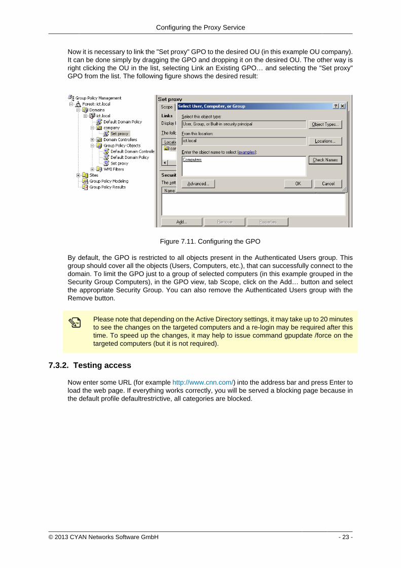
Configuring the Proxy Service
copy 2013 CYAN Networks Software GmbH - 23 -
Now it is necessary to link the Set proxy GPO to the desired OU (in this example OU company)It can be done simply by dragging the GPO and dropping it on the desired OU The other way isright clicking the OU in the list selecting Link an Existing GPOhellip and selecting the Set proxyGPO from the list The following figure shows the desired result
Figure 711 Configuring the GPO
By default the GPO is restricted to all objects present in the Authenticated Users group Thisgroup should cover all the objects (Users Computers etc) that can successfully connect to thedomain To limit the GPO just to a group of selected computers (in this example grouped in theSecurity Group Computers) in the GPO view tab Scope click on the Addhellip button and selectthe appropriate Security Group You can also remove the Authenticated Users group with theRemove button
Please note that depending on the Active Directory settings it may take up to 20 minutesto see the changes on the targeted computers and a re-login may be required after thistime To speed up the changes it may help to issue command gpupdate force on thetargeted computers (but it is not required)
732 Testing access
Now enter some URL (for example httpwwwcnncom) into the address bar and press Enter toload the web page If everything works correctly you will be served a blocking page because inthe default profile defaultrestrictive all categories are blocked
Configuring the Proxy Service
copy 2013 CYAN Networks Software GmbH - 24 -
Figure 712 Category blocking page
Since Soft Use Policy is enabled in the defaultrestrictive profile you may now click on click hereto access the page regardless of the profile settings denying it
To test the Anti Virus engine direct your browser to httpwwweicarorgdownloadeicarcom andacknowledge the Soft Use Policy that will allow you to download the content even though Archiveis not an allowed Application Type in the defaultrestrictive profile This link contains harmlesstesting code that was designed specifically for testing reactions of anti-virus engines There is noneed to be concerned that you will access a page with an actual virus on it
Figure 713 AV blocking of eicarcom download
Configuring the Proxy Service
copy 2013 CYAN Networks Software GmbH - 25 -
After the virus scanning will take place and if the scanning is successful the download will bedenied from the Anti Virus engine
Only integrated anti virus engines like ESET and Avira are capable of returning thevirus name
For performance reasons we strongly recommend you usage of the integrated Anti Virusengine
In case of any troubles please refer to the troubleshoot section of this document (see Appendix ATroubleshooting) or contact support at supportcyan-networkscom for help
copy 2013 CYAN Networks Software GmbH - 26 -
8 Initial Configuration
81 Initial Authentication Setup
Secure Web is installed on the Appliance with a default configuration This configuration includesfor the purpose of authentication an IP List instance named ldquoIP Listrdquo with one IP list namedldquoglobalrdquo representing ldquothe worldrdquo (00000) You can access this default instance by navigatinginto the menu ServicesAuthenticationInstances double clicking the IP list instance in the listand navigating to the IP List tab (as shown in the following figure)
Figure 81 IP Instance default configuration
According to the order of evaluation as defined in Section 83 ldquoInitial Profile Assignment Setuprdquothe IP List instance is evaluated first Consequently the global IP list which matches any IPaddress will affect all requests
82 Initial Profile Setup
Complementary to the default authentication configuration there is also a default setup of accessrules The profile tree shows the top level profile named organization and a sibling calleddefaultrestrictive
Figure 82 Profile default configuration
As shown in the Figure 82 ldquoProfile default configurationrdquo the defaultrestrictive profile appliesa rather strict type of Internet access by blocking all categories that are available in the CYANNetworks URL database
The following figure shows the General dialog found at Services Authentication Settingsincluding the setting for the default profile which gets applied to all connections without a dedicatedprofile assignment In this case it is the default defaultrestrictive profile
Initial Configuration
copy 2013 CYAN Networks Software GmbH - 27 -
Figure 83 Default profile used
83 Initial Profile Assignment Setup
Per default all requests served through the Secure Web Proxy are restricted by thedefaultrestrictive profile as set up in the General dialog found in Service Authentication Settings(see Section 82 ldquoInitial Profile Setuprdquo)
To assign profiles to different users groups or IPs in the network the administrator has to set upauthentication and assign profiles to the user objects
The following figure shows an example setup of an IP List authentication instance andassignments based on the IP objects It can be created in the menu Service Authentication Instances
Figure 84 Example IP List instance
In this example four IP objects are created based on the layout of the IP network A network forservers and QA machines is created and two single IP objects represent workstations
Initial Configuration
copy 2013 CYAN Networks Software GmbH - 28 -
In the following figure the server and QA networks are assigned to the defaultrestrictive profileThis profile is rather restrictive and blocks all categories per default This assignment can be donein the menu Services Profile Assignment
Figure 85 Example IP profile assignments
The two workstations in this example setup are assigned to the organisation profile which isa very relaxed setup as this profile allows any request made to the Secure Web Proxy Profileassignment can be modified by selecting some Authentication Instance from the list and usingappropriate action from the context menu New profile can be assigned by selecting Assign oneprofile existing profile assignment can be removed by selecting Remove profiles from selecteditem(s) More advanced manipulation can be done in Assign profiles with time rangeshellip
After finishing all desired changes do not forget to save them all using the Save button and thento apply them using the Apply button in the top right corner of the page
copy 2013 CYAN Networks Software GmbH - 29 -
9 Updating Upgrading the ApplianceIn order to get the latest product version of your CYAN Appliance go to the menu Appliances Maintenance Firmware
To start the update you have to press the Upgrade button as shown on the following figure
Figure 91 Firmware upgrade screen
After pressing the Upgrade button you will be taken to a different screen where you can performthe actual update of your Appliance (see Figure 92 ldquoUpgrade Service screen - upgraderdquo)
Pressing the Upgrade button will start an update procedure that includes completeshutdown of all services running on the Appliance This means any proxy functionalitywill unavailable until restart of the Appliance is performed
Again press the Upgrade button You will be informed about the ongoing update in the boxbellow the button In the example screen no update was neccessary and no new packages weredownloaded
Figure 92 Upgrade Service screen - upgrade
After the update is finished you are advised to restart your Appliance This can be performed byclicking the Restart button that appears below the information box (see the following figure)
Figure 93 Upgrade Service screen - upgrade
Updating Upgrading the Appliance
copy 2013 CYAN Networks Software GmbH - 30 -
When the restart of the Appliance is completed you can navigate back to the Web Admin Interfaceusing the browser navigation button
There is no need to perform periodic checks if updates are available Information aboutavailable updates of the Appliance can be found in the CYAN Networks newsletter It isnecessary to register in the company web pages to subscribe to it Please visit httpwwwcyan-networkscomindexphpenmy-cyan to register (registration is for free)
copy 2013 CYAN Networks Software GmbH - 31 -
10 Starting the Reporting SystemThe initial configuration of the appliance includes a pre-configured but yet inactive ReportingSystem The following actions need to be completed to activate the Reporting System
1 Setting up the Reporting Database
2 Enabling the Log Feed Service
It is strongly recommended to install the reporting database on a separate system Thisespecially applies for cluster setups where a local database setup is highly discouragedA local database system can cause performance impacts when reports are calculatedand is not synchronised in cluster environments
101 Login to the Reporting System
Point your browser to the address assigned via DHCP or the management IP as the case maybe Replace ltappliance-ipgt in the following URL with the real IP address of your Appliance
httpsltappliance-ipgt9992 (for example https 192168119992)
The welcome screen allows you to either access the Secure Web Web Admin Interface or theReporting System
Figure 101 Welcome screen
Click on Login next to CYAN Reporting System to navigate to the Web Admin Interface of theReporting System
The Reporting System uses different login credentials than the Secure Web You may want toassign a different password to the Secure Web login in order restrict the administration of themachine parameters and the reporting to different people
The default login values after setup are
bull User admin
Starting the Reporting System
copy 2013 CYAN Networks Software GmbH - 32 -
bull Password admin
We strongly recommended to change the administrator password as soon as possibleNavigate to the menu Users User and double-click on the admin user or click on theperson-shaped icon next to your login name in the top right corner of the screen to changethe password
102 Setting up the Reporting Database
Figure 102 Setup the reporting database
If you have not setup any database access previously at login you will be informed aboutincorrect values (as seen in figure Figure 102 ldquoSetup the reporting databaserdquo) There are manydifferent database engines supported for using the Reporting System
bull PostgreSQL 80 or higher
bull Microsoft SQL Server 2005 or higher
bull MySQL 50 or higher
bull Oracle
bull DB2
bull H2 Database
For each database engine there is available a short quide what SQL commands to issue tocorrectly make the initial database setup You can test the settings using the Test button
The configuration of the Reporting System database assumes you already have setupa database engine of your choice and you can connect to it If after filling in allrequired information a connection error still appears please check all the login credentialpriviledges firewall settings and whether the database engine daemon is running
Whenever any new version of the Reporting System should require any changes to the databaseyour explicit confirmation is requested in order to proceed with the upgrade That will be mostlikely your case since there is no database structure yet and it needs to be created An exampleof such upgrade request shows the following figure
Starting the Reporting System
copy 2013 CYAN Networks Software GmbH - 33 -
Figure 103 Upgrade of the reporting database
Database upgrades may take a long time and can cause significant impact on theoperation and performance of the system Therefore the Reporting System will neverupgrade the database automatically but leave this decision to the administrator
After a successful completion of the setup upgrade of the database a Login button appearsat the end of the page and allows you to go to the login screen
103 Enabling the Log-Feeder
In order to activate the import of the reporting information into the reporting database the logfeeder service of Secure Web must be enabled This service picks up the log files generated bySecure Web and feeds them into the reporting database
Change to the Secure Web administrative interface select the menu Services Logging Reporting Log and browse to the dialog Log Feeder as shown in the following screenshot
Figure 104 Log feeder
The default values in this dialog are prepared to operate with the Reporting System on the samemachine In case you want to run the Reporting System on a separate machine please refer tothe Secure Web Reference Guide that describes the necessary steps
Do not forget to save any changes you have made by the Save button and then apply them usingthe Apply button
The first time you enable the Log-Feeder it may time some time to generate output from all theavailable logs
copy 2013 CYAN Networks Software GmbH - 34 -
Appendix A Troubleshooting
A1 Getting access to the command line
A11 Access via SSH
The Appliance can be accessed using SSH protocol This access is enabled by the factorydefaults During the initial setup is created a special user account in the Appliances system withusername csupport and the same password as the one used for Super Administrator accountin the Web Admin Interface (in the following text denoted as Password) For connecting to theAppliance via SSH you also need to know the Appliances IP address (for example 19216811in the following text denoted as ltappliance-ipgt)
A111 From UnixLinux
Accessing the Appliance from a Unix based system is fairly easy In the command line issue thefollowing command
ssh csupportltappliance-ipgt
If this is the first time you are connecting to the Appliance via SSH from current system confirmthe security warning and input the Password when asked to
A112 From Microsoft Windows
Accessing the Appliance via SSH from a Windows system is a little more complicated Windowssystems do not have by default installed any SHH client programm so you will need to obtainone One of the most popular ones is a freeware software called PuTTY which does not requireany installation All versions are available for download from the following web page
httpwwwchiarkgreenendorguk~sgtathamputtydownloadhtml
A direct link to the latest executable 32bit version for Windows is following
httptheearthli~sgtathamputtylatestx86puttyexe
When the download is complete run the downloaded executable and the SSH client login screenshould appear (as you can see in Figure A1 ldquoPuTTY windowrdquo) In the window input logininformation in the Host Name (or IP address) field Use the same format (substitute the exampleIP address 19216811 with the real IP address of your Appliance) Then click on the Open buttonconfirm a security warning if it appears and input the Password when asked for one
Troubleshooting
copy 2013 CYAN Networks Software GmbH - 35 -
Figure A1 PuTTY window
Once you are logged in to the system you will be able to see a simple text menu providing quickaccess to some of the useful maintenance functions
Figure A2 Console main menu
Troubleshooting
copy 2013 CYAN Networks Software GmbH - 36 -
A12 Access using monitor and keyboard
With a keyboard and a monitor attached to your appliance machine you may login to thecommand line using the credentials of the csupport user (as described in the previous section)
After logging in to the system you will be able to see and operate the same way as shown inthe previous section
A2 Recover from an invalid IP address
In case that you have set up an IP address which is not reachable by your client PC there is analternative way to change the IP address of the appliance by using the command line interface(see Section A1 ldquoGetting access to the command linerdquo)
If you have already successfully logged into the system using the csupport account navigateto menu Network management Display interfaces to see the list of available interfaces on theAppliance Make a note of the name of the interface which IP address you want to change
Figure A3 Network interfaces
Press any key to return to the previous menu and this time choose Temporarily change networkconfiguration menu item You will be asked for a name of the interface you have noted down inthe previous step new IP address network mask and optionally gateway IP address
If you are connected to the appliance via SSH and you changed the IP address of theinterface to which you are currently connected the connection will be dropped withoutany warning and you will have to reconnect to the newly set up IP address
After changing the IP address of the Appliances port via console menu you haveto change the IP address again in the Web Admin Interface Please refer to theSection 65 ldquoChanging the IP Address(es)rdquo to get information about changing the IPaddress permanently Any changes done using the console menu will last just until areboot of the Appliance
copy 2013 CYAN Networks Software GmbH - 37 -
Appendix B Contact data
B1 How to contact our sales department
Tel +43 (1) 33933-0
Email salescyan-networkscom
B2 How to contact our support department
Tel +43 (1) 33933-333
Email supportcyan-networkscom
B21 Getting Support
In case you should have any technical problems or questions and would like to get support fromour team we kindly ask you to provide us with the following information
bull Description of your question or problem
bull The version information of the product
bull The version information of Secure Web can be found after logging into the Web AdminInterface in the top part of the screen
Figure B1 Version information of the Secure Web
bull The version information of the Reporting System can be found after login in the top part ofthe screen of the Web Admin Interface
Figure B2 Version information of the Reporting System
bull All the information contained in the screen found in menu Services Services Overview
bull In the case authentication is activated provide us with the method in place (via Windows Agentvia Linux Agent etc)
bull The deployment method of the Appliance (Out-of-line In-Line DMZ)
bull The operation mode of the Appliance (dedicated mode transparent mode)
Contact data
copy 2013 CYAN Networks Software GmbH - 38 -
bull Information about the environment (proxy cascades that are used firewalls and gatewaysinvolved in the infrastructure that are of relevance to the Appliance)
The appliance interface provides the possibility to create a support package that includes theconfiguration and log files of the system This package can help us to track down the issue easierand faster Please attach this package to your e-mail
In order to create a support pack navigate to menu Appliances Maintenance Support and clickon the Download button You may select the files you want to provide to our support team andthen download a package which we kindly ask you to send to our support email address
Figure B3 Support Package
Further documentation about the product as well as technical white papers that describe certainuse cases can be found in our documentation repository on our homepage
httpwwwcyan-networkscomdocumentation
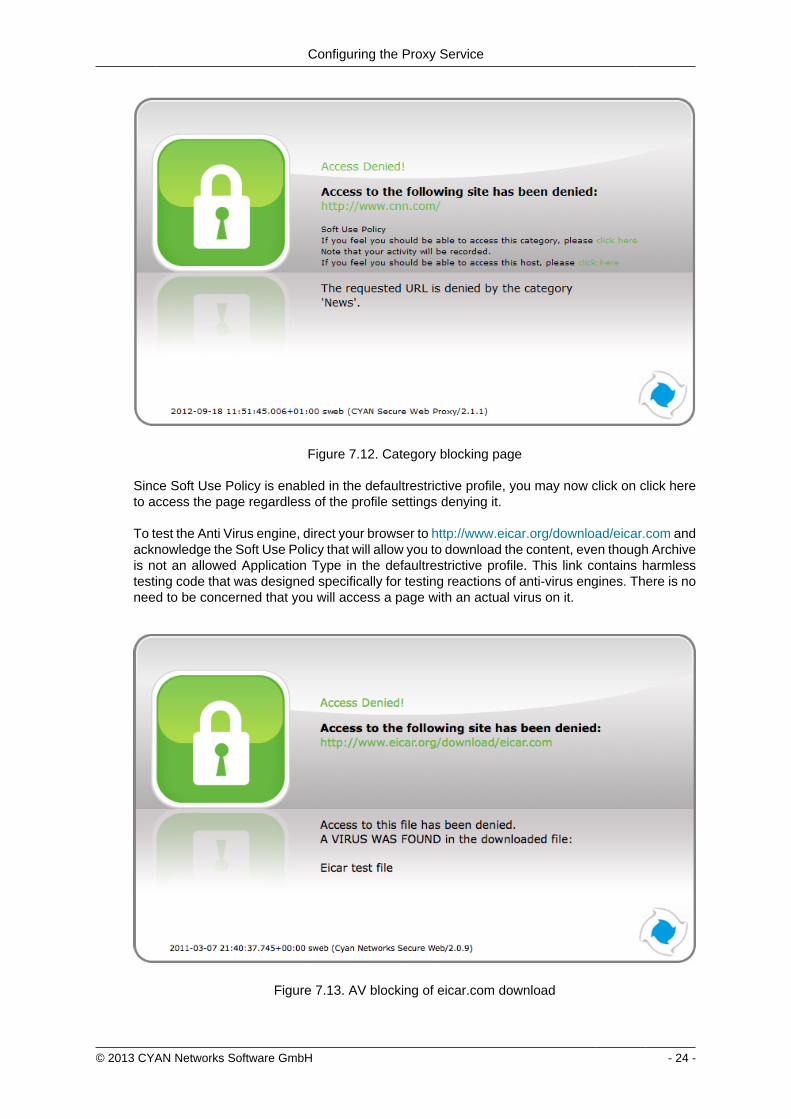
Configuring the Proxy Service
copy 2013 CYAN Networks Software GmbH - 24 -
Figure 712 Category blocking page
Since Soft Use Policy is enabled in the defaultrestrictive profile you may now click on click hereto access the page regardless of the profile settings denying it
To test the Anti Virus engine direct your browser to httpwwweicarorgdownloadeicarcom andacknowledge the Soft Use Policy that will allow you to download the content even though Archiveis not an allowed Application Type in the defaultrestrictive profile This link contains harmlesstesting code that was designed specifically for testing reactions of anti-virus engines There is noneed to be concerned that you will access a page with an actual virus on it
Figure 713 AV blocking of eicarcom download
Configuring the Proxy Service
copy 2013 CYAN Networks Software GmbH - 25 -
After the virus scanning will take place and if the scanning is successful the download will bedenied from the Anti Virus engine
Only integrated anti virus engines like ESET and Avira are capable of returning thevirus name
For performance reasons we strongly recommend you usage of the integrated Anti Virusengine
In case of any troubles please refer to the troubleshoot section of this document (see Appendix ATroubleshooting) or contact support at supportcyan-networkscom for help
copy 2013 CYAN Networks Software GmbH - 26 -
8 Initial Configuration
81 Initial Authentication Setup
Secure Web is installed on the Appliance with a default configuration This configuration includesfor the purpose of authentication an IP List instance named ldquoIP Listrdquo with one IP list namedldquoglobalrdquo representing ldquothe worldrdquo (00000) You can access this default instance by navigatinginto the menu ServicesAuthenticationInstances double clicking the IP list instance in the listand navigating to the IP List tab (as shown in the following figure)
Figure 81 IP Instance default configuration
According to the order of evaluation as defined in Section 83 ldquoInitial Profile Assignment Setuprdquothe IP List instance is evaluated first Consequently the global IP list which matches any IPaddress will affect all requests
82 Initial Profile Setup
Complementary to the default authentication configuration there is also a default setup of accessrules The profile tree shows the top level profile named organization and a sibling calleddefaultrestrictive
Figure 82 Profile default configuration
As shown in the Figure 82 ldquoProfile default configurationrdquo the defaultrestrictive profile appliesa rather strict type of Internet access by blocking all categories that are available in the CYANNetworks URL database
The following figure shows the General dialog found at Services Authentication Settingsincluding the setting for the default profile which gets applied to all connections without a dedicatedprofile assignment In this case it is the default defaultrestrictive profile
Initial Configuration
copy 2013 CYAN Networks Software GmbH - 27 -
Figure 83 Default profile used
83 Initial Profile Assignment Setup
Per default all requests served through the Secure Web Proxy are restricted by thedefaultrestrictive profile as set up in the General dialog found in Service Authentication Settings(see Section 82 ldquoInitial Profile Setuprdquo)
To assign profiles to different users groups or IPs in the network the administrator has to set upauthentication and assign profiles to the user objects
The following figure shows an example setup of an IP List authentication instance andassignments based on the IP objects It can be created in the menu Service Authentication Instances
Figure 84 Example IP List instance
In this example four IP objects are created based on the layout of the IP network A network forservers and QA machines is created and two single IP objects represent workstations
Initial Configuration
copy 2013 CYAN Networks Software GmbH - 28 -
In the following figure the server and QA networks are assigned to the defaultrestrictive profileThis profile is rather restrictive and blocks all categories per default This assignment can be donein the menu Services Profile Assignment
Figure 85 Example IP profile assignments
The two workstations in this example setup are assigned to the organisation profile which isa very relaxed setup as this profile allows any request made to the Secure Web Proxy Profileassignment can be modified by selecting some Authentication Instance from the list and usingappropriate action from the context menu New profile can be assigned by selecting Assign oneprofile existing profile assignment can be removed by selecting Remove profiles from selecteditem(s) More advanced manipulation can be done in Assign profiles with time rangeshellip
After finishing all desired changes do not forget to save them all using the Save button and thento apply them using the Apply button in the top right corner of the page
copy 2013 CYAN Networks Software GmbH - 29 -
9 Updating Upgrading the ApplianceIn order to get the latest product version of your CYAN Appliance go to the menu Appliances Maintenance Firmware
To start the update you have to press the Upgrade button as shown on the following figure
Figure 91 Firmware upgrade screen
After pressing the Upgrade button you will be taken to a different screen where you can performthe actual update of your Appliance (see Figure 92 ldquoUpgrade Service screen - upgraderdquo)
Pressing the Upgrade button will start an update procedure that includes completeshutdown of all services running on the Appliance This means any proxy functionalitywill unavailable until restart of the Appliance is performed
Again press the Upgrade button You will be informed about the ongoing update in the boxbellow the button In the example screen no update was neccessary and no new packages weredownloaded
Figure 92 Upgrade Service screen - upgrade
After the update is finished you are advised to restart your Appliance This can be performed byclicking the Restart button that appears below the information box (see the following figure)
Figure 93 Upgrade Service screen - upgrade
Updating Upgrading the Appliance
copy 2013 CYAN Networks Software GmbH - 30 -
When the restart of the Appliance is completed you can navigate back to the Web Admin Interfaceusing the browser navigation button
There is no need to perform periodic checks if updates are available Information aboutavailable updates of the Appliance can be found in the CYAN Networks newsletter It isnecessary to register in the company web pages to subscribe to it Please visit httpwwwcyan-networkscomindexphpenmy-cyan to register (registration is for free)
copy 2013 CYAN Networks Software GmbH - 31 -
10 Starting the Reporting SystemThe initial configuration of the appliance includes a pre-configured but yet inactive ReportingSystem The following actions need to be completed to activate the Reporting System
1 Setting up the Reporting Database
2 Enabling the Log Feed Service
It is strongly recommended to install the reporting database on a separate system Thisespecially applies for cluster setups where a local database setup is highly discouragedA local database system can cause performance impacts when reports are calculatedand is not synchronised in cluster environments
101 Login to the Reporting System
Point your browser to the address assigned via DHCP or the management IP as the case maybe Replace ltappliance-ipgt in the following URL with the real IP address of your Appliance
httpsltappliance-ipgt9992 (for example https 192168119992)
The welcome screen allows you to either access the Secure Web Web Admin Interface or theReporting System
Figure 101 Welcome screen
Click on Login next to CYAN Reporting System to navigate to the Web Admin Interface of theReporting System
The Reporting System uses different login credentials than the Secure Web You may want toassign a different password to the Secure Web login in order restrict the administration of themachine parameters and the reporting to different people
The default login values after setup are
bull User admin
Starting the Reporting System
copy 2013 CYAN Networks Software GmbH - 32 -
bull Password admin
We strongly recommended to change the administrator password as soon as possibleNavigate to the menu Users User and double-click on the admin user or click on theperson-shaped icon next to your login name in the top right corner of the screen to changethe password
102 Setting up the Reporting Database
Figure 102 Setup the reporting database
If you have not setup any database access previously at login you will be informed aboutincorrect values (as seen in figure Figure 102 ldquoSetup the reporting databaserdquo) There are manydifferent database engines supported for using the Reporting System
bull PostgreSQL 80 or higher
bull Microsoft SQL Server 2005 or higher
bull MySQL 50 or higher
bull Oracle
bull DB2
bull H2 Database
For each database engine there is available a short quide what SQL commands to issue tocorrectly make the initial database setup You can test the settings using the Test button
The configuration of the Reporting System database assumes you already have setupa database engine of your choice and you can connect to it If after filling in allrequired information a connection error still appears please check all the login credentialpriviledges firewall settings and whether the database engine daemon is running
Whenever any new version of the Reporting System should require any changes to the databaseyour explicit confirmation is requested in order to proceed with the upgrade That will be mostlikely your case since there is no database structure yet and it needs to be created An exampleof such upgrade request shows the following figure
Starting the Reporting System
copy 2013 CYAN Networks Software GmbH - 33 -
Figure 103 Upgrade of the reporting database
Database upgrades may take a long time and can cause significant impact on theoperation and performance of the system Therefore the Reporting System will neverupgrade the database automatically but leave this decision to the administrator
After a successful completion of the setup upgrade of the database a Login button appearsat the end of the page and allows you to go to the login screen
103 Enabling the Log-Feeder
In order to activate the import of the reporting information into the reporting database the logfeeder service of Secure Web must be enabled This service picks up the log files generated bySecure Web and feeds them into the reporting database
Change to the Secure Web administrative interface select the menu Services Logging Reporting Log and browse to the dialog Log Feeder as shown in the following screenshot
Figure 104 Log feeder
The default values in this dialog are prepared to operate with the Reporting System on the samemachine In case you want to run the Reporting System on a separate machine please refer tothe Secure Web Reference Guide that describes the necessary steps
Do not forget to save any changes you have made by the Save button and then apply them usingthe Apply button
The first time you enable the Log-Feeder it may time some time to generate output from all theavailable logs
copy 2013 CYAN Networks Software GmbH - 34 -
Appendix A Troubleshooting
A1 Getting access to the command line
A11 Access via SSH
The Appliance can be accessed using SSH protocol This access is enabled by the factorydefaults During the initial setup is created a special user account in the Appliances system withusername csupport and the same password as the one used for Super Administrator accountin the Web Admin Interface (in the following text denoted as Password) For connecting to theAppliance via SSH you also need to know the Appliances IP address (for example 19216811in the following text denoted as ltappliance-ipgt)
A111 From UnixLinux
Accessing the Appliance from a Unix based system is fairly easy In the command line issue thefollowing command
ssh csupportltappliance-ipgt
If this is the first time you are connecting to the Appliance via SSH from current system confirmthe security warning and input the Password when asked to
A112 From Microsoft Windows
Accessing the Appliance via SSH from a Windows system is a little more complicated Windowssystems do not have by default installed any SHH client programm so you will need to obtainone One of the most popular ones is a freeware software called PuTTY which does not requireany installation All versions are available for download from the following web page
httpwwwchiarkgreenendorguk~sgtathamputtydownloadhtml
A direct link to the latest executable 32bit version for Windows is following
httptheearthli~sgtathamputtylatestx86puttyexe
When the download is complete run the downloaded executable and the SSH client login screenshould appear (as you can see in Figure A1 ldquoPuTTY windowrdquo) In the window input logininformation in the Host Name (or IP address) field Use the same format (substitute the exampleIP address 19216811 with the real IP address of your Appliance) Then click on the Open buttonconfirm a security warning if it appears and input the Password when asked for one
Troubleshooting
copy 2013 CYAN Networks Software GmbH - 35 -
Figure A1 PuTTY window
Once you are logged in to the system you will be able to see a simple text menu providing quickaccess to some of the useful maintenance functions
Figure A2 Console main menu
Troubleshooting
copy 2013 CYAN Networks Software GmbH - 36 -
A12 Access using monitor and keyboard
With a keyboard and a monitor attached to your appliance machine you may login to thecommand line using the credentials of the csupport user (as described in the previous section)
After logging in to the system you will be able to see and operate the same way as shown inthe previous section
A2 Recover from an invalid IP address
In case that you have set up an IP address which is not reachable by your client PC there is analternative way to change the IP address of the appliance by using the command line interface(see Section A1 ldquoGetting access to the command linerdquo)
If you have already successfully logged into the system using the csupport account navigateto menu Network management Display interfaces to see the list of available interfaces on theAppliance Make a note of the name of the interface which IP address you want to change
Figure A3 Network interfaces
Press any key to return to the previous menu and this time choose Temporarily change networkconfiguration menu item You will be asked for a name of the interface you have noted down inthe previous step new IP address network mask and optionally gateway IP address
If you are connected to the appliance via SSH and you changed the IP address of theinterface to which you are currently connected the connection will be dropped withoutany warning and you will have to reconnect to the newly set up IP address
After changing the IP address of the Appliances port via console menu you haveto change the IP address again in the Web Admin Interface Please refer to theSection 65 ldquoChanging the IP Address(es)rdquo to get information about changing the IPaddress permanently Any changes done using the console menu will last just until areboot of the Appliance
copy 2013 CYAN Networks Software GmbH - 37 -
Appendix B Contact data
B1 How to contact our sales department
Tel +43 (1) 33933-0
Email salescyan-networkscom
B2 How to contact our support department
Tel +43 (1) 33933-333
Email supportcyan-networkscom
B21 Getting Support
In case you should have any technical problems or questions and would like to get support fromour team we kindly ask you to provide us with the following information
bull Description of your question or problem
bull The version information of the product
bull The version information of Secure Web can be found after logging into the Web AdminInterface in the top part of the screen
Figure B1 Version information of the Secure Web
bull The version information of the Reporting System can be found after login in the top part ofthe screen of the Web Admin Interface
Figure B2 Version information of the Reporting System
bull All the information contained in the screen found in menu Services Services Overview
bull In the case authentication is activated provide us with the method in place (via Windows Agentvia Linux Agent etc)
bull The deployment method of the Appliance (Out-of-line In-Line DMZ)
bull The operation mode of the Appliance (dedicated mode transparent mode)
Contact data
copy 2013 CYAN Networks Software GmbH - 38 -
bull Information about the environment (proxy cascades that are used firewalls and gatewaysinvolved in the infrastructure that are of relevance to the Appliance)
The appliance interface provides the possibility to create a support package that includes theconfiguration and log files of the system This package can help us to track down the issue easierand faster Please attach this package to your e-mail
In order to create a support pack navigate to menu Appliances Maintenance Support and clickon the Download button You may select the files you want to provide to our support team andthen download a package which we kindly ask you to send to our support email address
Figure B3 Support Package
Further documentation about the product as well as technical white papers that describe certainuse cases can be found in our documentation repository on our homepage
httpwwwcyan-networkscomdocumentation
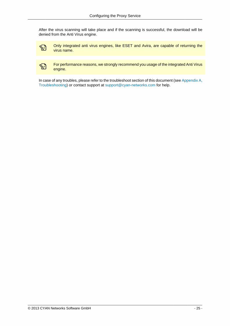
Configuring the Proxy Service
copy 2013 CYAN Networks Software GmbH - 25 -
After the virus scanning will take place and if the scanning is successful the download will bedenied from the Anti Virus engine
Only integrated anti virus engines like ESET and Avira are capable of returning thevirus name
For performance reasons we strongly recommend you usage of the integrated Anti Virusengine
In case of any troubles please refer to the troubleshoot section of this document (see Appendix ATroubleshooting) or contact support at supportcyan-networkscom for help
copy 2013 CYAN Networks Software GmbH - 26 -
8 Initial Configuration
81 Initial Authentication Setup
Secure Web is installed on the Appliance with a default configuration This configuration includesfor the purpose of authentication an IP List instance named ldquoIP Listrdquo with one IP list namedldquoglobalrdquo representing ldquothe worldrdquo (00000) You can access this default instance by navigatinginto the menu ServicesAuthenticationInstances double clicking the IP list instance in the listand navigating to the IP List tab (as shown in the following figure)
Figure 81 IP Instance default configuration
According to the order of evaluation as defined in Section 83 ldquoInitial Profile Assignment Setuprdquothe IP List instance is evaluated first Consequently the global IP list which matches any IPaddress will affect all requests
82 Initial Profile Setup
Complementary to the default authentication configuration there is also a default setup of accessrules The profile tree shows the top level profile named organization and a sibling calleddefaultrestrictive
Figure 82 Profile default configuration
As shown in the Figure 82 ldquoProfile default configurationrdquo the defaultrestrictive profile appliesa rather strict type of Internet access by blocking all categories that are available in the CYANNetworks URL database
The following figure shows the General dialog found at Services Authentication Settingsincluding the setting for the default profile which gets applied to all connections without a dedicatedprofile assignment In this case it is the default defaultrestrictive profile
Initial Configuration
copy 2013 CYAN Networks Software GmbH - 27 -
Figure 83 Default profile used
83 Initial Profile Assignment Setup
Per default all requests served through the Secure Web Proxy are restricted by thedefaultrestrictive profile as set up in the General dialog found in Service Authentication Settings(see Section 82 ldquoInitial Profile Setuprdquo)
To assign profiles to different users groups or IPs in the network the administrator has to set upauthentication and assign profiles to the user objects
The following figure shows an example setup of an IP List authentication instance andassignments based on the IP objects It can be created in the menu Service Authentication Instances
Figure 84 Example IP List instance
In this example four IP objects are created based on the layout of the IP network A network forservers and QA machines is created and two single IP objects represent workstations
Initial Configuration
copy 2013 CYAN Networks Software GmbH - 28 -
In the following figure the server and QA networks are assigned to the defaultrestrictive profileThis profile is rather restrictive and blocks all categories per default This assignment can be donein the menu Services Profile Assignment
Figure 85 Example IP profile assignments
The two workstations in this example setup are assigned to the organisation profile which isa very relaxed setup as this profile allows any request made to the Secure Web Proxy Profileassignment can be modified by selecting some Authentication Instance from the list and usingappropriate action from the context menu New profile can be assigned by selecting Assign oneprofile existing profile assignment can be removed by selecting Remove profiles from selecteditem(s) More advanced manipulation can be done in Assign profiles with time rangeshellip
After finishing all desired changes do not forget to save them all using the Save button and thento apply them using the Apply button in the top right corner of the page
copy 2013 CYAN Networks Software GmbH - 29 -
9 Updating Upgrading the ApplianceIn order to get the latest product version of your CYAN Appliance go to the menu Appliances Maintenance Firmware
To start the update you have to press the Upgrade button as shown on the following figure
Figure 91 Firmware upgrade screen
After pressing the Upgrade button you will be taken to a different screen where you can performthe actual update of your Appliance (see Figure 92 ldquoUpgrade Service screen - upgraderdquo)
Pressing the Upgrade button will start an update procedure that includes completeshutdown of all services running on the Appliance This means any proxy functionalitywill unavailable until restart of the Appliance is performed
Again press the Upgrade button You will be informed about the ongoing update in the boxbellow the button In the example screen no update was neccessary and no new packages weredownloaded
Figure 92 Upgrade Service screen - upgrade
After the update is finished you are advised to restart your Appliance This can be performed byclicking the Restart button that appears below the information box (see the following figure)
Figure 93 Upgrade Service screen - upgrade
Updating Upgrading the Appliance
copy 2013 CYAN Networks Software GmbH - 30 -
When the restart of the Appliance is completed you can navigate back to the Web Admin Interfaceusing the browser navigation button
There is no need to perform periodic checks if updates are available Information aboutavailable updates of the Appliance can be found in the CYAN Networks newsletter It isnecessary to register in the company web pages to subscribe to it Please visit httpwwwcyan-networkscomindexphpenmy-cyan to register (registration is for free)
copy 2013 CYAN Networks Software GmbH - 31 -
10 Starting the Reporting SystemThe initial configuration of the appliance includes a pre-configured but yet inactive ReportingSystem The following actions need to be completed to activate the Reporting System
1 Setting up the Reporting Database
2 Enabling the Log Feed Service
It is strongly recommended to install the reporting database on a separate system Thisespecially applies for cluster setups where a local database setup is highly discouragedA local database system can cause performance impacts when reports are calculatedand is not synchronised in cluster environments
101 Login to the Reporting System
Point your browser to the address assigned via DHCP or the management IP as the case maybe Replace ltappliance-ipgt in the following URL with the real IP address of your Appliance
httpsltappliance-ipgt9992 (for example https 192168119992)
The welcome screen allows you to either access the Secure Web Web Admin Interface or theReporting System
Figure 101 Welcome screen
Click on Login next to CYAN Reporting System to navigate to the Web Admin Interface of theReporting System
The Reporting System uses different login credentials than the Secure Web You may want toassign a different password to the Secure Web login in order restrict the administration of themachine parameters and the reporting to different people
The default login values after setup are
bull User admin
Starting the Reporting System
copy 2013 CYAN Networks Software GmbH - 32 -
bull Password admin
We strongly recommended to change the administrator password as soon as possibleNavigate to the menu Users User and double-click on the admin user or click on theperson-shaped icon next to your login name in the top right corner of the screen to changethe password
102 Setting up the Reporting Database
Figure 102 Setup the reporting database
If you have not setup any database access previously at login you will be informed aboutincorrect values (as seen in figure Figure 102 ldquoSetup the reporting databaserdquo) There are manydifferent database engines supported for using the Reporting System
bull PostgreSQL 80 or higher
bull Microsoft SQL Server 2005 or higher
bull MySQL 50 or higher
bull Oracle
bull DB2
bull H2 Database
For each database engine there is available a short quide what SQL commands to issue tocorrectly make the initial database setup You can test the settings using the Test button
The configuration of the Reporting System database assumes you already have setupa database engine of your choice and you can connect to it If after filling in allrequired information a connection error still appears please check all the login credentialpriviledges firewall settings and whether the database engine daemon is running
Whenever any new version of the Reporting System should require any changes to the databaseyour explicit confirmation is requested in order to proceed with the upgrade That will be mostlikely your case since there is no database structure yet and it needs to be created An exampleof such upgrade request shows the following figure
Starting the Reporting System
copy 2013 CYAN Networks Software GmbH - 33 -
Figure 103 Upgrade of the reporting database
Database upgrades may take a long time and can cause significant impact on theoperation and performance of the system Therefore the Reporting System will neverupgrade the database automatically but leave this decision to the administrator
After a successful completion of the setup upgrade of the database a Login button appearsat the end of the page and allows you to go to the login screen
103 Enabling the Log-Feeder
In order to activate the import of the reporting information into the reporting database the logfeeder service of Secure Web must be enabled This service picks up the log files generated bySecure Web and feeds them into the reporting database
Change to the Secure Web administrative interface select the menu Services Logging Reporting Log and browse to the dialog Log Feeder as shown in the following screenshot
Figure 104 Log feeder
The default values in this dialog are prepared to operate with the Reporting System on the samemachine In case you want to run the Reporting System on a separate machine please refer tothe Secure Web Reference Guide that describes the necessary steps
Do not forget to save any changes you have made by the Save button and then apply them usingthe Apply button
The first time you enable the Log-Feeder it may time some time to generate output from all theavailable logs
copy 2013 CYAN Networks Software GmbH - 34 -
Appendix A Troubleshooting
A1 Getting access to the command line
A11 Access via SSH
The Appliance can be accessed using SSH protocol This access is enabled by the factorydefaults During the initial setup is created a special user account in the Appliances system withusername csupport and the same password as the one used for Super Administrator accountin the Web Admin Interface (in the following text denoted as Password) For connecting to theAppliance via SSH you also need to know the Appliances IP address (for example 19216811in the following text denoted as ltappliance-ipgt)
A111 From UnixLinux
Accessing the Appliance from a Unix based system is fairly easy In the command line issue thefollowing command
ssh csupportltappliance-ipgt
If this is the first time you are connecting to the Appliance via SSH from current system confirmthe security warning and input the Password when asked to
A112 From Microsoft Windows
Accessing the Appliance via SSH from a Windows system is a little more complicated Windowssystems do not have by default installed any SHH client programm so you will need to obtainone One of the most popular ones is a freeware software called PuTTY which does not requireany installation All versions are available for download from the following web page
httpwwwchiarkgreenendorguk~sgtathamputtydownloadhtml
A direct link to the latest executable 32bit version for Windows is following
httptheearthli~sgtathamputtylatestx86puttyexe
When the download is complete run the downloaded executable and the SSH client login screenshould appear (as you can see in Figure A1 ldquoPuTTY windowrdquo) In the window input logininformation in the Host Name (or IP address) field Use the same format (substitute the exampleIP address 19216811 with the real IP address of your Appliance) Then click on the Open buttonconfirm a security warning if it appears and input the Password when asked for one
Troubleshooting
copy 2013 CYAN Networks Software GmbH - 35 -
Figure A1 PuTTY window
Once you are logged in to the system you will be able to see a simple text menu providing quickaccess to some of the useful maintenance functions
Figure A2 Console main menu
Troubleshooting
copy 2013 CYAN Networks Software GmbH - 36 -
A12 Access using monitor and keyboard
With a keyboard and a monitor attached to your appliance machine you may login to thecommand line using the credentials of the csupport user (as described in the previous section)
After logging in to the system you will be able to see and operate the same way as shown inthe previous section
A2 Recover from an invalid IP address
In case that you have set up an IP address which is not reachable by your client PC there is analternative way to change the IP address of the appliance by using the command line interface(see Section A1 ldquoGetting access to the command linerdquo)
If you have already successfully logged into the system using the csupport account navigateto menu Network management Display interfaces to see the list of available interfaces on theAppliance Make a note of the name of the interface which IP address you want to change
Figure A3 Network interfaces
Press any key to return to the previous menu and this time choose Temporarily change networkconfiguration menu item You will be asked for a name of the interface you have noted down inthe previous step new IP address network mask and optionally gateway IP address
If you are connected to the appliance via SSH and you changed the IP address of theinterface to which you are currently connected the connection will be dropped withoutany warning and you will have to reconnect to the newly set up IP address
After changing the IP address of the Appliances port via console menu you haveto change the IP address again in the Web Admin Interface Please refer to theSection 65 ldquoChanging the IP Address(es)rdquo to get information about changing the IPaddress permanently Any changes done using the console menu will last just until areboot of the Appliance
copy 2013 CYAN Networks Software GmbH - 37 -
Appendix B Contact data
B1 How to contact our sales department
Tel +43 (1) 33933-0
Email salescyan-networkscom
B2 How to contact our support department
Tel +43 (1) 33933-333
Email supportcyan-networkscom
B21 Getting Support
In case you should have any technical problems or questions and would like to get support fromour team we kindly ask you to provide us with the following information
bull Description of your question or problem
bull The version information of the product
bull The version information of Secure Web can be found after logging into the Web AdminInterface in the top part of the screen
Figure B1 Version information of the Secure Web
bull The version information of the Reporting System can be found after login in the top part ofthe screen of the Web Admin Interface
Figure B2 Version information of the Reporting System
bull All the information contained in the screen found in menu Services Services Overview
bull In the case authentication is activated provide us with the method in place (via Windows Agentvia Linux Agent etc)
bull The deployment method of the Appliance (Out-of-line In-Line DMZ)
bull The operation mode of the Appliance (dedicated mode transparent mode)
Contact data
copy 2013 CYAN Networks Software GmbH - 38 -
bull Information about the environment (proxy cascades that are used firewalls and gatewaysinvolved in the infrastructure that are of relevance to the Appliance)
The appliance interface provides the possibility to create a support package that includes theconfiguration and log files of the system This package can help us to track down the issue easierand faster Please attach this package to your e-mail
In order to create a support pack navigate to menu Appliances Maintenance Support and clickon the Download button You may select the files you want to provide to our support team andthen download a package which we kindly ask you to send to our support email address
Figure B3 Support Package
Further documentation about the product as well as technical white papers that describe certainuse cases can be found in our documentation repository on our homepage
httpwwwcyan-networkscomdocumentation
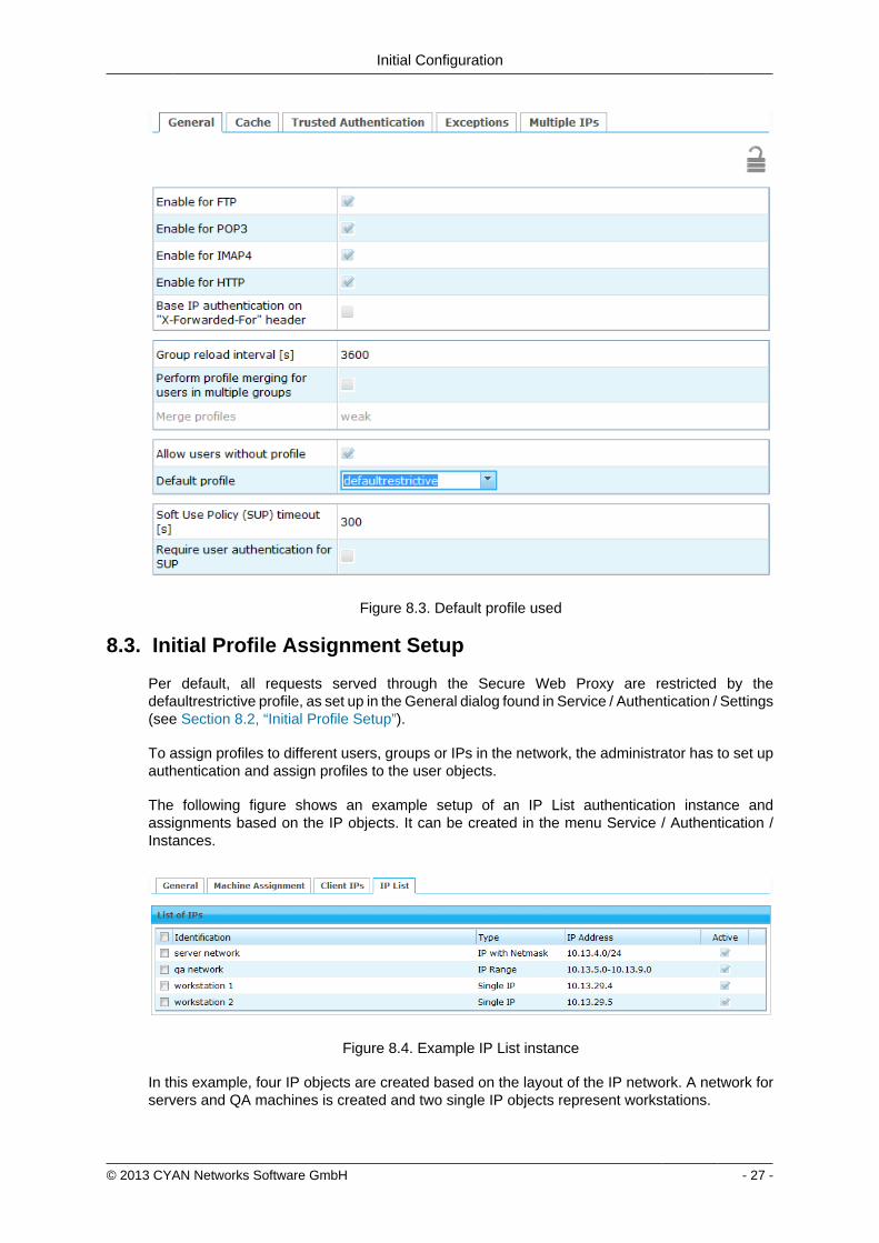
Initial Configuration
copy 2013 CYAN Networks Software GmbH - 27 -
Figure 83 Default profile used
83 Initial Profile Assignment Setup
Per default all requests served through the Secure Web Proxy are restricted by thedefaultrestrictive profile as set up in the General dialog found in Service Authentication Settings(see Section 82 ldquoInitial Profile Setuprdquo)
To assign profiles to different users groups or IPs in the network the administrator has to set upauthentication and assign profiles to the user objects
The following figure shows an example setup of an IP List authentication instance andassignments based on the IP objects It can be created in the menu Service Authentication Instances
Figure 84 Example IP List instance
In this example four IP objects are created based on the layout of the IP network A network forservers and QA machines is created and two single IP objects represent workstations
Initial Configuration
copy 2013 CYAN Networks Software GmbH - 28 -
In the following figure the server and QA networks are assigned to the defaultrestrictive profileThis profile is rather restrictive and blocks all categories per default This assignment can be donein the menu Services Profile Assignment
Figure 85 Example IP profile assignments
The two workstations in this example setup are assigned to the organisation profile which isa very relaxed setup as this profile allows any request made to the Secure Web Proxy Profileassignment can be modified by selecting some Authentication Instance from the list and usingappropriate action from the context menu New profile can be assigned by selecting Assign oneprofile existing profile assignment can be removed by selecting Remove profiles from selecteditem(s) More advanced manipulation can be done in Assign profiles with time rangeshellip
After finishing all desired changes do not forget to save them all using the Save button and thento apply them using the Apply button in the top right corner of the page
copy 2013 CYAN Networks Software GmbH - 29 -
9 Updating Upgrading the ApplianceIn order to get the latest product version of your CYAN Appliance go to the menu Appliances Maintenance Firmware
To start the update you have to press the Upgrade button as shown on the following figure
Figure 91 Firmware upgrade screen
After pressing the Upgrade button you will be taken to a different screen where you can performthe actual update of your Appliance (see Figure 92 ldquoUpgrade Service screen - upgraderdquo)
Pressing the Upgrade button will start an update procedure that includes completeshutdown of all services running on the Appliance This means any proxy functionalitywill unavailable until restart of the Appliance is performed
Again press the Upgrade button You will be informed about the ongoing update in the boxbellow the button In the example screen no update was neccessary and no new packages weredownloaded
Figure 92 Upgrade Service screen - upgrade
After the update is finished you are advised to restart your Appliance This can be performed byclicking the Restart button that appears below the information box (see the following figure)
Figure 93 Upgrade Service screen - upgrade
Updating Upgrading the Appliance
copy 2013 CYAN Networks Software GmbH - 30 -
When the restart of the Appliance is completed you can navigate back to the Web Admin Interfaceusing the browser navigation button
There is no need to perform periodic checks if updates are available Information aboutavailable updates of the Appliance can be found in the CYAN Networks newsletter It isnecessary to register in the company web pages to subscribe to it Please visit httpwwwcyan-networkscomindexphpenmy-cyan to register (registration is for free)
copy 2013 CYAN Networks Software GmbH - 31 -
10 Starting the Reporting SystemThe initial configuration of the appliance includes a pre-configured but yet inactive ReportingSystem The following actions need to be completed to activate the Reporting System
1 Setting up the Reporting Database
2 Enabling the Log Feed Service
It is strongly recommended to install the reporting database on a separate system Thisespecially applies for cluster setups where a local database setup is highly discouragedA local database system can cause performance impacts when reports are calculatedand is not synchronised in cluster environments
101 Login to the Reporting System
Point your browser to the address assigned via DHCP or the management IP as the case maybe Replace ltappliance-ipgt in the following URL with the real IP address of your Appliance
httpsltappliance-ipgt9992 (for example https 192168119992)
The welcome screen allows you to either access the Secure Web Web Admin Interface or theReporting System
Figure 101 Welcome screen
Click on Login next to CYAN Reporting System to navigate to the Web Admin Interface of theReporting System
The Reporting System uses different login credentials than the Secure Web You may want toassign a different password to the Secure Web login in order restrict the administration of themachine parameters and the reporting to different people
The default login values after setup are
bull User admin
Starting the Reporting System
copy 2013 CYAN Networks Software GmbH - 32 -
bull Password admin
We strongly recommended to change the administrator password as soon as possibleNavigate to the menu Users User and double-click on the admin user or click on theperson-shaped icon next to your login name in the top right corner of the screen to changethe password
102 Setting up the Reporting Database
Figure 102 Setup the reporting database
If you have not setup any database access previously at login you will be informed aboutincorrect values (as seen in figure Figure 102 ldquoSetup the reporting databaserdquo) There are manydifferent database engines supported for using the Reporting System
bull PostgreSQL 80 or higher
bull Microsoft SQL Server 2005 or higher
bull MySQL 50 or higher
bull Oracle
bull DB2
bull H2 Database
For each database engine there is available a short quide what SQL commands to issue tocorrectly make the initial database setup You can test the settings using the Test button
The configuration of the Reporting System database assumes you already have setupa database engine of your choice and you can connect to it If after filling in allrequired information a connection error still appears please check all the login credentialpriviledges firewall settings and whether the database engine daemon is running
Whenever any new version of the Reporting System should require any changes to the databaseyour explicit confirmation is requested in order to proceed with the upgrade That will be mostlikely your case since there is no database structure yet and it needs to be created An exampleof such upgrade request shows the following figure
Starting the Reporting System
copy 2013 CYAN Networks Software GmbH - 33 -
Figure 103 Upgrade of the reporting database
Database upgrades may take a long time and can cause significant impact on theoperation and performance of the system Therefore the Reporting System will neverupgrade the database automatically but leave this decision to the administrator
After a successful completion of the setup upgrade of the database a Login button appearsat the end of the page and allows you to go to the login screen
103 Enabling the Log-Feeder
In order to activate the import of the reporting information into the reporting database the logfeeder service of Secure Web must be enabled This service picks up the log files generated bySecure Web and feeds them into the reporting database
Change to the Secure Web administrative interface select the menu Services Logging Reporting Log and browse to the dialog Log Feeder as shown in the following screenshot
Figure 104 Log feeder
The default values in this dialog are prepared to operate with the Reporting System on the samemachine In case you want to run the Reporting System on a separate machine please refer tothe Secure Web Reference Guide that describes the necessary steps
Do not forget to save any changes you have made by the Save button and then apply them usingthe Apply button
The first time you enable the Log-Feeder it may time some time to generate output from all theavailable logs
copy 2013 CYAN Networks Software GmbH - 34 -
Appendix A Troubleshooting
A1 Getting access to the command line
A11 Access via SSH
The Appliance can be accessed using SSH protocol This access is enabled by the factorydefaults During the initial setup is created a special user account in the Appliances system withusername csupport and the same password as the one used for Super Administrator accountin the Web Admin Interface (in the following text denoted as Password) For connecting to theAppliance via SSH you also need to know the Appliances IP address (for example 19216811in the following text denoted as ltappliance-ipgt)
A111 From UnixLinux
Accessing the Appliance from a Unix based system is fairly easy In the command line issue thefollowing command
ssh csupportltappliance-ipgt
If this is the first time you are connecting to the Appliance via SSH from current system confirmthe security warning and input the Password when asked to
A112 From Microsoft Windows
Accessing the Appliance via SSH from a Windows system is a little more complicated Windowssystems do not have by default installed any SHH client programm so you will need to obtainone One of the most popular ones is a freeware software called PuTTY which does not requireany installation All versions are available for download from the following web page
httpwwwchiarkgreenendorguk~sgtathamputtydownloadhtml
A direct link to the latest executable 32bit version for Windows is following
httptheearthli~sgtathamputtylatestx86puttyexe
When the download is complete run the downloaded executable and the SSH client login screenshould appear (as you can see in Figure A1 ldquoPuTTY windowrdquo) In the window input logininformation in the Host Name (or IP address) field Use the same format (substitute the exampleIP address 19216811 with the real IP address of your Appliance) Then click on the Open buttonconfirm a security warning if it appears and input the Password when asked for one
Troubleshooting
copy 2013 CYAN Networks Software GmbH - 35 -
Figure A1 PuTTY window
Once you are logged in to the system you will be able to see a simple text menu providing quickaccess to some of the useful maintenance functions
Figure A2 Console main menu
Troubleshooting
copy 2013 CYAN Networks Software GmbH - 36 -
A12 Access using monitor and keyboard
With a keyboard and a monitor attached to your appliance machine you may login to thecommand line using the credentials of the csupport user (as described in the previous section)
After logging in to the system you will be able to see and operate the same way as shown inthe previous section
A2 Recover from an invalid IP address
In case that you have set up an IP address which is not reachable by your client PC there is analternative way to change the IP address of the appliance by using the command line interface(see Section A1 ldquoGetting access to the command linerdquo)
If you have already successfully logged into the system using the csupport account navigateto menu Network management Display interfaces to see the list of available interfaces on theAppliance Make a note of the name of the interface which IP address you want to change
Figure A3 Network interfaces
Press any key to return to the previous menu and this time choose Temporarily change networkconfiguration menu item You will be asked for a name of the interface you have noted down inthe previous step new IP address network mask and optionally gateway IP address
If you are connected to the appliance via SSH and you changed the IP address of theinterface to which you are currently connected the connection will be dropped withoutany warning and you will have to reconnect to the newly set up IP address
After changing the IP address of the Appliances port via console menu you haveto change the IP address again in the Web Admin Interface Please refer to theSection 65 ldquoChanging the IP Address(es)rdquo to get information about changing the IPaddress permanently Any changes done using the console menu will last just until areboot of the Appliance
copy 2013 CYAN Networks Software GmbH - 37 -
Appendix B Contact data
B1 How to contact our sales department
Tel +43 (1) 33933-0
Email salescyan-networkscom
B2 How to contact our support department
Tel +43 (1) 33933-333
Email supportcyan-networkscom
B21 Getting Support
In case you should have any technical problems or questions and would like to get support fromour team we kindly ask you to provide us with the following information
bull Description of your question or problem
bull The version information of the product
bull The version information of Secure Web can be found after logging into the Web AdminInterface in the top part of the screen
Figure B1 Version information of the Secure Web
bull The version information of the Reporting System can be found after login in the top part ofthe screen of the Web Admin Interface
Figure B2 Version information of the Reporting System
bull All the information contained in the screen found in menu Services Services Overview
bull In the case authentication is activated provide us with the method in place (via Windows Agentvia Linux Agent etc)
bull The deployment method of the Appliance (Out-of-line In-Line DMZ)
bull The operation mode of the Appliance (dedicated mode transparent mode)
Contact data
copy 2013 CYAN Networks Software GmbH - 38 -
bull Information about the environment (proxy cascades that are used firewalls and gatewaysinvolved in the infrastructure that are of relevance to the Appliance)
The appliance interface provides the possibility to create a support package that includes theconfiguration and log files of the system This package can help us to track down the issue easierand faster Please attach this package to your e-mail
In order to create a support pack navigate to menu Appliances Maintenance Support and clickon the Download button You may select the files you want to provide to our support team andthen download a package which we kindly ask you to send to our support email address
Figure B3 Support Package
Further documentation about the product as well as technical white papers that describe certainuse cases can be found in our documentation repository on our homepage
httpwwwcyan-networkscomdocumentation
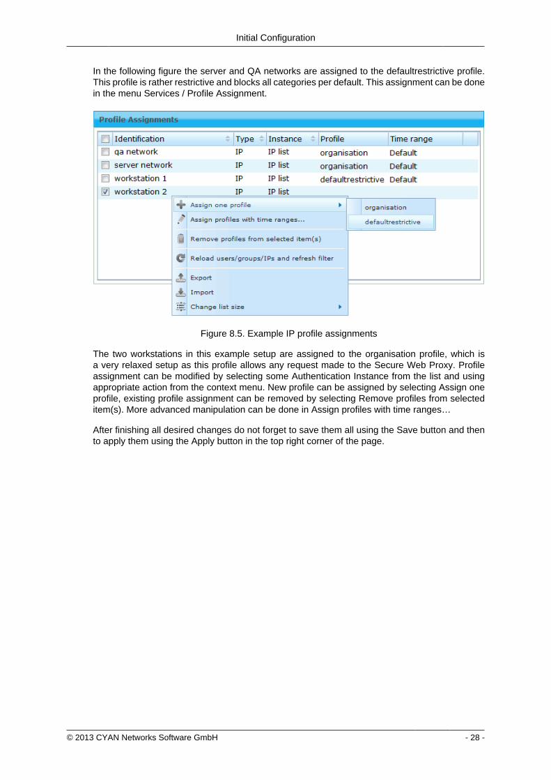
Initial Configuration
copy 2013 CYAN Networks Software GmbH - 28 -
In the following figure the server and QA networks are assigned to the defaultrestrictive profileThis profile is rather restrictive and blocks all categories per default This assignment can be donein the menu Services Profile Assignment
Figure 85 Example IP profile assignments
The two workstations in this example setup are assigned to the organisation profile which isa very relaxed setup as this profile allows any request made to the Secure Web Proxy Profileassignment can be modified by selecting some Authentication Instance from the list and usingappropriate action from the context menu New profile can be assigned by selecting Assign oneprofile existing profile assignment can be removed by selecting Remove profiles from selecteditem(s) More advanced manipulation can be done in Assign profiles with time rangeshellip
After finishing all desired changes do not forget to save them all using the Save button and thento apply them using the Apply button in the top right corner of the page
copy 2013 CYAN Networks Software GmbH - 29 -
9 Updating Upgrading the ApplianceIn order to get the latest product version of your CYAN Appliance go to the menu Appliances Maintenance Firmware
To start the update you have to press the Upgrade button as shown on the following figure
Figure 91 Firmware upgrade screen
After pressing the Upgrade button you will be taken to a different screen where you can performthe actual update of your Appliance (see Figure 92 ldquoUpgrade Service screen - upgraderdquo)
Pressing the Upgrade button will start an update procedure that includes completeshutdown of all services running on the Appliance This means any proxy functionalitywill unavailable until restart of the Appliance is performed
Again press the Upgrade button You will be informed about the ongoing update in the boxbellow the button In the example screen no update was neccessary and no new packages weredownloaded
Figure 92 Upgrade Service screen - upgrade
After the update is finished you are advised to restart your Appliance This can be performed byclicking the Restart button that appears below the information box (see the following figure)
Figure 93 Upgrade Service screen - upgrade
Updating Upgrading the Appliance
copy 2013 CYAN Networks Software GmbH - 30 -
When the restart of the Appliance is completed you can navigate back to the Web Admin Interfaceusing the browser navigation button
There is no need to perform periodic checks if updates are available Information aboutavailable updates of the Appliance can be found in the CYAN Networks newsletter It isnecessary to register in the company web pages to subscribe to it Please visit httpwwwcyan-networkscomindexphpenmy-cyan to register (registration is for free)
copy 2013 CYAN Networks Software GmbH - 31 -
10 Starting the Reporting SystemThe initial configuration of the appliance includes a pre-configured but yet inactive ReportingSystem The following actions need to be completed to activate the Reporting System
1 Setting up the Reporting Database
2 Enabling the Log Feed Service
It is strongly recommended to install the reporting database on a separate system Thisespecially applies for cluster setups where a local database setup is highly discouragedA local database system can cause performance impacts when reports are calculatedand is not synchronised in cluster environments
101 Login to the Reporting System
Point your browser to the address assigned via DHCP or the management IP as the case maybe Replace ltappliance-ipgt in the following URL with the real IP address of your Appliance
httpsltappliance-ipgt9992 (for example https 192168119992)
The welcome screen allows you to either access the Secure Web Web Admin Interface or theReporting System
Figure 101 Welcome screen
Click on Login next to CYAN Reporting System to navigate to the Web Admin Interface of theReporting System
The Reporting System uses different login credentials than the Secure Web You may want toassign a different password to the Secure Web login in order restrict the administration of themachine parameters and the reporting to different people
The default login values after setup are
bull User admin
Starting the Reporting System
copy 2013 CYAN Networks Software GmbH - 32 -
bull Password admin
We strongly recommended to change the administrator password as soon as possibleNavigate to the menu Users User and double-click on the admin user or click on theperson-shaped icon next to your login name in the top right corner of the screen to changethe password
102 Setting up the Reporting Database
Figure 102 Setup the reporting database
If you have not setup any database access previously at login you will be informed aboutincorrect values (as seen in figure Figure 102 ldquoSetup the reporting databaserdquo) There are manydifferent database engines supported for using the Reporting System
bull PostgreSQL 80 or higher
bull Microsoft SQL Server 2005 or higher
bull MySQL 50 or higher
bull Oracle
bull DB2
bull H2 Database
For each database engine there is available a short quide what SQL commands to issue tocorrectly make the initial database setup You can test the settings using the Test button
The configuration of the Reporting System database assumes you already have setupa database engine of your choice and you can connect to it If after filling in allrequired information a connection error still appears please check all the login credentialpriviledges firewall settings and whether the database engine daemon is running
Whenever any new version of the Reporting System should require any changes to the databaseyour explicit confirmation is requested in order to proceed with the upgrade That will be mostlikely your case since there is no database structure yet and it needs to be created An exampleof such upgrade request shows the following figure
Starting the Reporting System
copy 2013 CYAN Networks Software GmbH - 33 -
Figure 103 Upgrade of the reporting database
Database upgrades may take a long time and can cause significant impact on theoperation and performance of the system Therefore the Reporting System will neverupgrade the database automatically but leave this decision to the administrator
After a successful completion of the setup upgrade of the database a Login button appearsat the end of the page and allows you to go to the login screen
103 Enabling the Log-Feeder
In order to activate the import of the reporting information into the reporting database the logfeeder service of Secure Web must be enabled This service picks up the log files generated bySecure Web and feeds them into the reporting database
Change to the Secure Web administrative interface select the menu Services Logging Reporting Log and browse to the dialog Log Feeder as shown in the following screenshot
Figure 104 Log feeder
The default values in this dialog are prepared to operate with the Reporting System on the samemachine In case you want to run the Reporting System on a separate machine please refer tothe Secure Web Reference Guide that describes the necessary steps
Do not forget to save any changes you have made by the Save button and then apply them usingthe Apply button
The first time you enable the Log-Feeder it may time some time to generate output from all theavailable logs
copy 2013 CYAN Networks Software GmbH - 34 -
Appendix A Troubleshooting
A1 Getting access to the command line
A11 Access via SSH
The Appliance can be accessed using SSH protocol This access is enabled by the factorydefaults During the initial setup is created a special user account in the Appliances system withusername csupport and the same password as the one used for Super Administrator accountin the Web Admin Interface (in the following text denoted as Password) For connecting to theAppliance via SSH you also need to know the Appliances IP address (for example 19216811in the following text denoted as ltappliance-ipgt)
A111 From UnixLinux
Accessing the Appliance from a Unix based system is fairly easy In the command line issue thefollowing command
ssh csupportltappliance-ipgt
If this is the first time you are connecting to the Appliance via SSH from current system confirmthe security warning and input the Password when asked to
A112 From Microsoft Windows
Accessing the Appliance via SSH from a Windows system is a little more complicated Windowssystems do not have by default installed any SHH client programm so you will need to obtainone One of the most popular ones is a freeware software called PuTTY which does not requireany installation All versions are available for download from the following web page
httpwwwchiarkgreenendorguk~sgtathamputtydownloadhtml
A direct link to the latest executable 32bit version for Windows is following
httptheearthli~sgtathamputtylatestx86puttyexe
When the download is complete run the downloaded executable and the SSH client login screenshould appear (as you can see in Figure A1 ldquoPuTTY windowrdquo) In the window input logininformation in the Host Name (or IP address) field Use the same format (substitute the exampleIP address 19216811 with the real IP address of your Appliance) Then click on the Open buttonconfirm a security warning if it appears and input the Password when asked for one
Troubleshooting
copy 2013 CYAN Networks Software GmbH - 35 -
Figure A1 PuTTY window
Once you are logged in to the system you will be able to see a simple text menu providing quickaccess to some of the useful maintenance functions
Figure A2 Console main menu
Troubleshooting
copy 2013 CYAN Networks Software GmbH - 36 -
A12 Access using monitor and keyboard
With a keyboard and a monitor attached to your appliance machine you may login to thecommand line using the credentials of the csupport user (as described in the previous section)
After logging in to the system you will be able to see and operate the same way as shown inthe previous section
A2 Recover from an invalid IP address
In case that you have set up an IP address which is not reachable by your client PC there is analternative way to change the IP address of the appliance by using the command line interface(see Section A1 ldquoGetting access to the command linerdquo)
If you have already successfully logged into the system using the csupport account navigateto menu Network management Display interfaces to see the list of available interfaces on theAppliance Make a note of the name of the interface which IP address you want to change
Figure A3 Network interfaces
Press any key to return to the previous menu and this time choose Temporarily change networkconfiguration menu item You will be asked for a name of the interface you have noted down inthe previous step new IP address network mask and optionally gateway IP address
If you are connected to the appliance via SSH and you changed the IP address of theinterface to which you are currently connected the connection will be dropped withoutany warning and you will have to reconnect to the newly set up IP address
After changing the IP address of the Appliances port via console menu you haveto change the IP address again in the Web Admin Interface Please refer to theSection 65 ldquoChanging the IP Address(es)rdquo to get information about changing the IPaddress permanently Any changes done using the console menu will last just until areboot of the Appliance
copy 2013 CYAN Networks Software GmbH - 37 -
Appendix B Contact data
B1 How to contact our sales department
Tel +43 (1) 33933-0
Email salescyan-networkscom
B2 How to contact our support department
Tel +43 (1) 33933-333
Email supportcyan-networkscom
B21 Getting Support
In case you should have any technical problems or questions and would like to get support fromour team we kindly ask you to provide us with the following information
bull Description of your question or problem
bull The version information of the product
bull The version information of Secure Web can be found after logging into the Web AdminInterface in the top part of the screen
Figure B1 Version information of the Secure Web
bull The version information of the Reporting System can be found after login in the top part ofthe screen of the Web Admin Interface
Figure B2 Version information of the Reporting System
bull All the information contained in the screen found in menu Services Services Overview
bull In the case authentication is activated provide us with the method in place (via Windows Agentvia Linux Agent etc)
bull The deployment method of the Appliance (Out-of-line In-Line DMZ)
bull The operation mode of the Appliance (dedicated mode transparent mode)
Contact data
copy 2013 CYAN Networks Software GmbH - 38 -
bull Information about the environment (proxy cascades that are used firewalls and gatewaysinvolved in the infrastructure that are of relevance to the Appliance)
The appliance interface provides the possibility to create a support package that includes theconfiguration and log files of the system This package can help us to track down the issue easierand faster Please attach this package to your e-mail
In order to create a support pack navigate to menu Appliances Maintenance Support and clickon the Download button You may select the files you want to provide to our support team andthen download a package which we kindly ask you to send to our support email address
Figure B3 Support Package
Further documentation about the product as well as technical white papers that describe certainuse cases can be found in our documentation repository on our homepage
httpwwwcyan-networkscomdocumentation
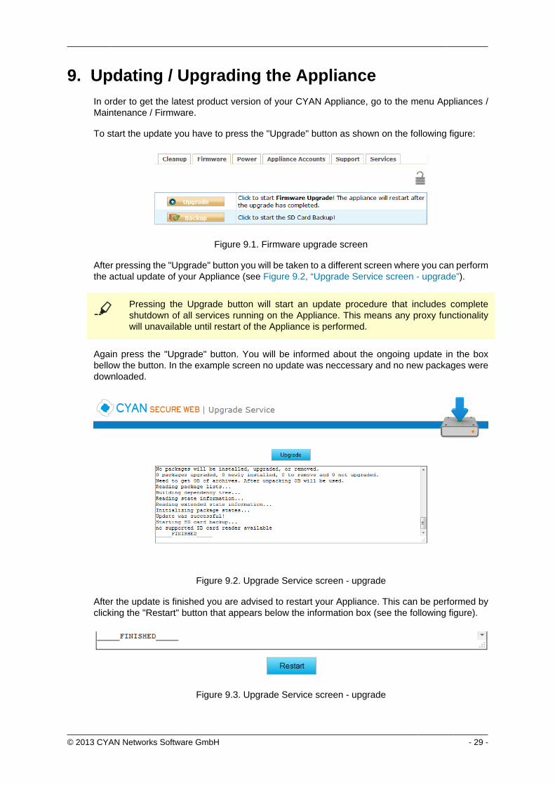
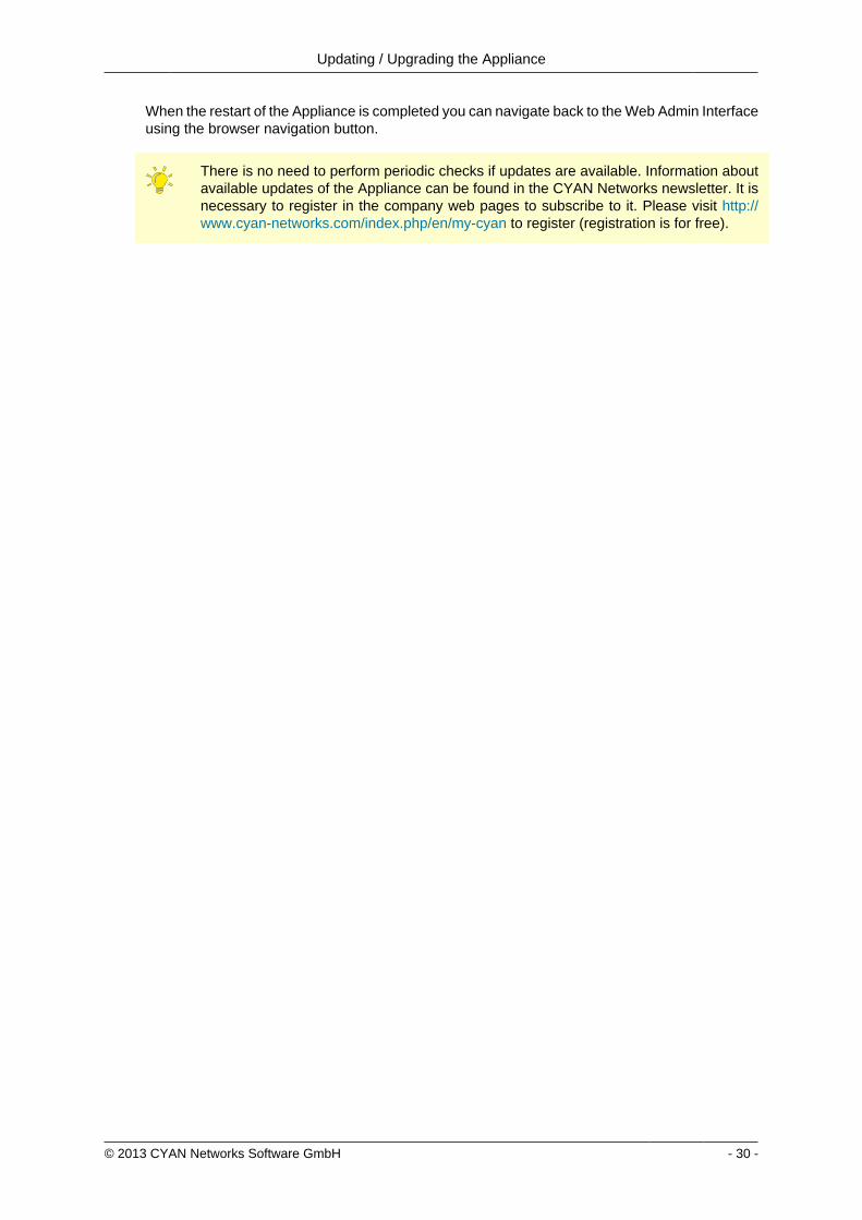
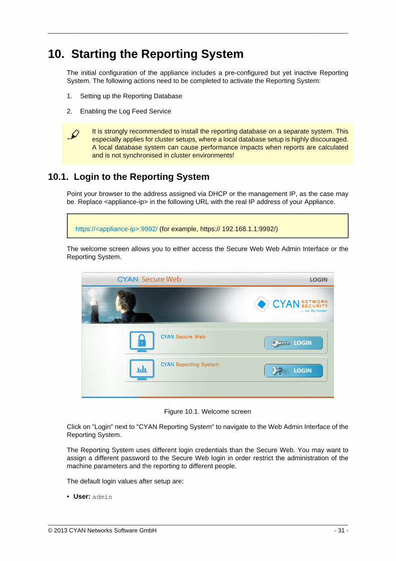
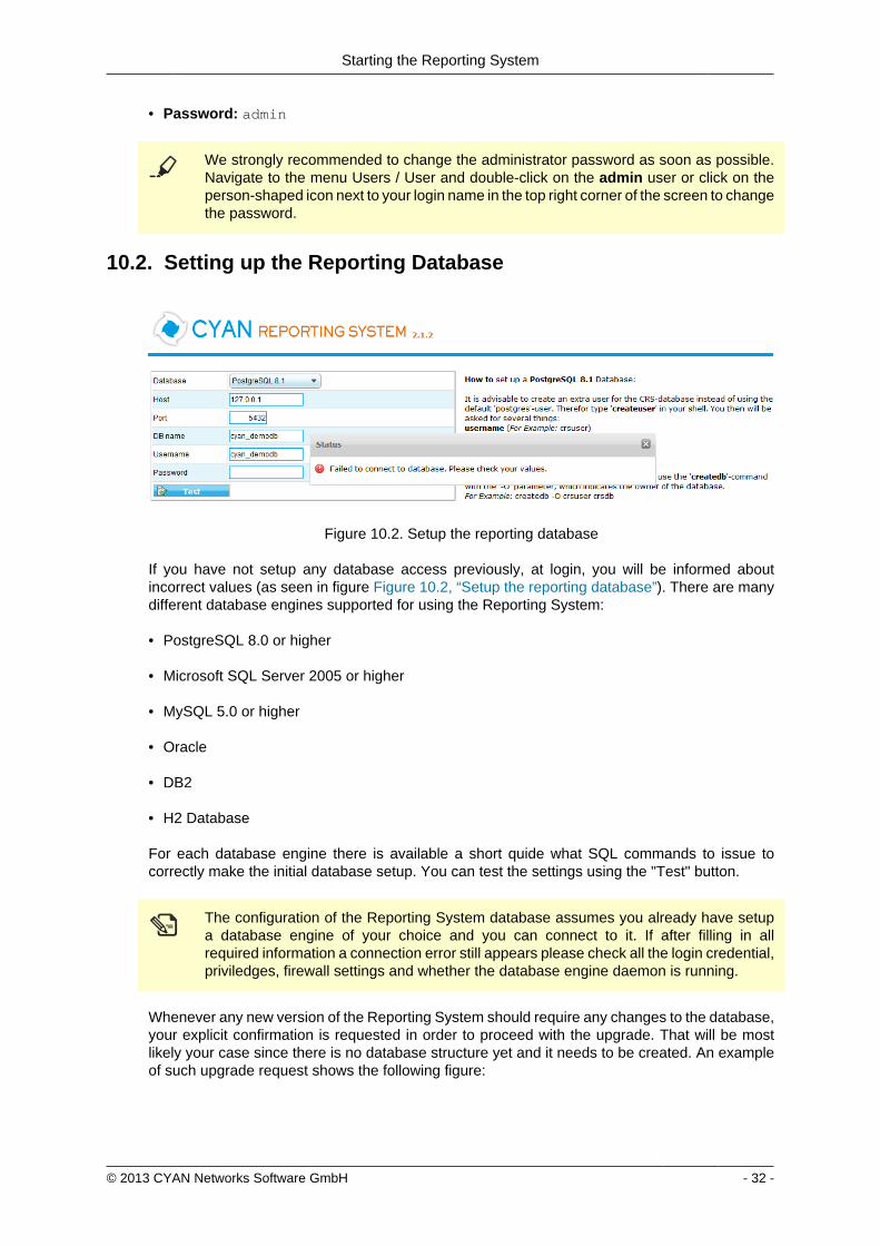
Starting the Reporting System
copy 2013 CYAN Networks Software GmbH - 32 -
bull Password admin
We strongly recommended to change the administrator password as soon as possibleNavigate to the menu Users User and double-click on the admin user or click on theperson-shaped icon next to your login name in the top right corner of the screen to changethe password
102 Setting up the Reporting Database
Figure 102 Setup the reporting database
If you have not setup any database access previously at login you will be informed aboutincorrect values (as seen in figure Figure 102 ldquoSetup the reporting databaserdquo) There are manydifferent database engines supported for using the Reporting System
bull PostgreSQL 80 or higher
bull Microsoft SQL Server 2005 or higher
bull MySQL 50 or higher
bull Oracle
bull DB2
bull H2 Database
For each database engine there is available a short quide what SQL commands to issue tocorrectly make the initial database setup You can test the settings using the Test button
The configuration of the Reporting System database assumes you already have setupa database engine of your choice and you can connect to it If after filling in allrequired information a connection error still appears please check all the login credentialpriviledges firewall settings and whether the database engine daemon is running
Whenever any new version of the Reporting System should require any changes to the databaseyour explicit confirmation is requested in order to proceed with the upgrade That will be mostlikely your case since there is no database structure yet and it needs to be created An exampleof such upgrade request shows the following figure
Starting the Reporting System
copy 2013 CYAN Networks Software GmbH - 33 -
Figure 103 Upgrade of the reporting database
Database upgrades may take a long time and can cause significant impact on theoperation and performance of the system Therefore the Reporting System will neverupgrade the database automatically but leave this decision to the administrator
After a successful completion of the setup upgrade of the database a Login button appearsat the end of the page and allows you to go to the login screen
103 Enabling the Log-Feeder
In order to activate the import of the reporting information into the reporting database the logfeeder service of Secure Web must be enabled This service picks up the log files generated bySecure Web and feeds them into the reporting database
Change to the Secure Web administrative interface select the menu Services Logging Reporting Log and browse to the dialog Log Feeder as shown in the following screenshot
Figure 104 Log feeder
The default values in this dialog are prepared to operate with the Reporting System on the samemachine In case you want to run the Reporting System on a separate machine please refer tothe Secure Web Reference Guide that describes the necessary steps
Do not forget to save any changes you have made by the Save button and then apply them usingthe Apply button
The first time you enable the Log-Feeder it may time some time to generate output from all theavailable logs
copy 2013 CYAN Networks Software GmbH - 34 -
Appendix A Troubleshooting
A1 Getting access to the command line
A11 Access via SSH
The Appliance can be accessed using SSH protocol This access is enabled by the factorydefaults During the initial setup is created a special user account in the Appliances system withusername csupport and the same password as the one used for Super Administrator accountin the Web Admin Interface (in the following text denoted as Password) For connecting to theAppliance via SSH you also need to know the Appliances IP address (for example 19216811in the following text denoted as ltappliance-ipgt)
A111 From UnixLinux
Accessing the Appliance from a Unix based system is fairly easy In the command line issue thefollowing command
ssh csupportltappliance-ipgt
If this is the first time you are connecting to the Appliance via SSH from current system confirmthe security warning and input the Password when asked to
A112 From Microsoft Windows
Accessing the Appliance via SSH from a Windows system is a little more complicated Windowssystems do not have by default installed any SHH client programm so you will need to obtainone One of the most popular ones is a freeware software called PuTTY which does not requireany installation All versions are available for download from the following web page
httpwwwchiarkgreenendorguk~sgtathamputtydownloadhtml
A direct link to the latest executable 32bit version for Windows is following
httptheearthli~sgtathamputtylatestx86puttyexe
When the download is complete run the downloaded executable and the SSH client login screenshould appear (as you can see in Figure A1 ldquoPuTTY windowrdquo) In the window input logininformation in the Host Name (or IP address) field Use the same format (substitute the exampleIP address 19216811 with the real IP address of your Appliance) Then click on the Open buttonconfirm a security warning if it appears and input the Password when asked for one
Troubleshooting
copy 2013 CYAN Networks Software GmbH - 35 -
Figure A1 PuTTY window
Once you are logged in to the system you will be able to see a simple text menu providing quickaccess to some of the useful maintenance functions
Figure A2 Console main menu
Troubleshooting
copy 2013 CYAN Networks Software GmbH - 36 -
A12 Access using monitor and keyboard
With a keyboard and a monitor attached to your appliance machine you may login to thecommand line using the credentials of the csupport user (as described in the previous section)
After logging in to the system you will be able to see and operate the same way as shown inthe previous section
A2 Recover from an invalid IP address
In case that you have set up an IP address which is not reachable by your client PC there is analternative way to change the IP address of the appliance by using the command line interface(see Section A1 ldquoGetting access to the command linerdquo)
If you have already successfully logged into the system using the csupport account navigateto menu Network management Display interfaces to see the list of available interfaces on theAppliance Make a note of the name of the interface which IP address you want to change
Figure A3 Network interfaces
Press any key to return to the previous menu and this time choose Temporarily change networkconfiguration menu item You will be asked for a name of the interface you have noted down inthe previous step new IP address network mask and optionally gateway IP address
If you are connected to the appliance via SSH and you changed the IP address of theinterface to which you are currently connected the connection will be dropped withoutany warning and you will have to reconnect to the newly set up IP address
After changing the IP address of the Appliances port via console menu you haveto change the IP address again in the Web Admin Interface Please refer to theSection 65 ldquoChanging the IP Address(es)rdquo to get information about changing the IPaddress permanently Any changes done using the console menu will last just until areboot of the Appliance
copy 2013 CYAN Networks Software GmbH - 37 -
Appendix B Contact data
B1 How to contact our sales department
Tel +43 (1) 33933-0
Email salescyan-networkscom
B2 How to contact our support department
Tel +43 (1) 33933-333
Email supportcyan-networkscom
B21 Getting Support
In case you should have any technical problems or questions and would like to get support fromour team we kindly ask you to provide us with the following information
bull Description of your question or problem
bull The version information of the product
bull The version information of Secure Web can be found after logging into the Web AdminInterface in the top part of the screen
Figure B1 Version information of the Secure Web
bull The version information of the Reporting System can be found after login in the top part ofthe screen of the Web Admin Interface
Figure B2 Version information of the Reporting System
bull All the information contained in the screen found in menu Services Services Overview
bull In the case authentication is activated provide us with the method in place (via Windows Agentvia Linux Agent etc)
bull The deployment method of the Appliance (Out-of-line In-Line DMZ)
bull The operation mode of the Appliance (dedicated mode transparent mode)
Contact data
copy 2013 CYAN Networks Software GmbH - 38 -
bull Information about the environment (proxy cascades that are used firewalls and gatewaysinvolved in the infrastructure that are of relevance to the Appliance)
The appliance interface provides the possibility to create a support package that includes theconfiguration and log files of the system This package can help us to track down the issue easierand faster Please attach this package to your e-mail
In order to create a support pack navigate to menu Appliances Maintenance Support and clickon the Download button You may select the files you want to provide to our support team andthen download a package which we kindly ask you to send to our support email address
Figure B3 Support Package
Further documentation about the product as well as technical white papers that describe certainuse cases can be found in our documentation repository on our homepage
httpwwwcyan-networkscomdocumentation
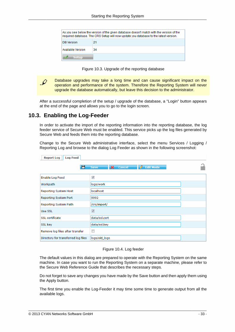
Starting the Reporting System
copy 2013 CYAN Networks Software GmbH - 33 -
Figure 103 Upgrade of the reporting database
Database upgrades may take a long time and can cause significant impact on theoperation and performance of the system Therefore the Reporting System will neverupgrade the database automatically but leave this decision to the administrator
After a successful completion of the setup upgrade of the database a Login button appearsat the end of the page and allows you to go to the login screen
103 Enabling the Log-Feeder
In order to activate the import of the reporting information into the reporting database the logfeeder service of Secure Web must be enabled This service picks up the log files generated bySecure Web and feeds them into the reporting database
Change to the Secure Web administrative interface select the menu Services Logging Reporting Log and browse to the dialog Log Feeder as shown in the following screenshot
Figure 104 Log feeder
The default values in this dialog are prepared to operate with the Reporting System on the samemachine In case you want to run the Reporting System on a separate machine please refer tothe Secure Web Reference Guide that describes the necessary steps
Do not forget to save any changes you have made by the Save button and then apply them usingthe Apply button
The first time you enable the Log-Feeder it may time some time to generate output from all theavailable logs
copy 2013 CYAN Networks Software GmbH - 34 -
Appendix A Troubleshooting
A1 Getting access to the command line
A11 Access via SSH
The Appliance can be accessed using SSH protocol This access is enabled by the factorydefaults During the initial setup is created a special user account in the Appliances system withusername csupport and the same password as the one used for Super Administrator accountin the Web Admin Interface (in the following text denoted as Password) For connecting to theAppliance via SSH you also need to know the Appliances IP address (for example 19216811in the following text denoted as ltappliance-ipgt)
A111 From UnixLinux
Accessing the Appliance from a Unix based system is fairly easy In the command line issue thefollowing command
ssh csupportltappliance-ipgt
If this is the first time you are connecting to the Appliance via SSH from current system confirmthe security warning and input the Password when asked to
A112 From Microsoft Windows
Accessing the Appliance via SSH from a Windows system is a little more complicated Windowssystems do not have by default installed any SHH client programm so you will need to obtainone One of the most popular ones is a freeware software called PuTTY which does not requireany installation All versions are available for download from the following web page
httpwwwchiarkgreenendorguk~sgtathamputtydownloadhtml
A direct link to the latest executable 32bit version for Windows is following
httptheearthli~sgtathamputtylatestx86puttyexe
When the download is complete run the downloaded executable and the SSH client login screenshould appear (as you can see in Figure A1 ldquoPuTTY windowrdquo) In the window input logininformation in the Host Name (or IP address) field Use the same format (substitute the exampleIP address 19216811 with the real IP address of your Appliance) Then click on the Open buttonconfirm a security warning if it appears and input the Password when asked for one
Troubleshooting
copy 2013 CYAN Networks Software GmbH - 35 -
Figure A1 PuTTY window
Once you are logged in to the system you will be able to see a simple text menu providing quickaccess to some of the useful maintenance functions
Figure A2 Console main menu
Troubleshooting
copy 2013 CYAN Networks Software GmbH - 36 -
A12 Access using monitor and keyboard
With a keyboard and a monitor attached to your appliance machine you may login to thecommand line using the credentials of the csupport user (as described in the previous section)
After logging in to the system you will be able to see and operate the same way as shown inthe previous section
A2 Recover from an invalid IP address
In case that you have set up an IP address which is not reachable by your client PC there is analternative way to change the IP address of the appliance by using the command line interface(see Section A1 ldquoGetting access to the command linerdquo)
If you have already successfully logged into the system using the csupport account navigateto menu Network management Display interfaces to see the list of available interfaces on theAppliance Make a note of the name of the interface which IP address you want to change
Figure A3 Network interfaces
Press any key to return to the previous menu and this time choose Temporarily change networkconfiguration menu item You will be asked for a name of the interface you have noted down inthe previous step new IP address network mask and optionally gateway IP address
If you are connected to the appliance via SSH and you changed the IP address of theinterface to which you are currently connected the connection will be dropped withoutany warning and you will have to reconnect to the newly set up IP address
After changing the IP address of the Appliances port via console menu you haveto change the IP address again in the Web Admin Interface Please refer to theSection 65 ldquoChanging the IP Address(es)rdquo to get information about changing the IPaddress permanently Any changes done using the console menu will last just until areboot of the Appliance
copy 2013 CYAN Networks Software GmbH - 37 -
Appendix B Contact data
B1 How to contact our sales department
Tel +43 (1) 33933-0
Email salescyan-networkscom
B2 How to contact our support department
Tel +43 (1) 33933-333
Email supportcyan-networkscom
B21 Getting Support
In case you should have any technical problems or questions and would like to get support fromour team we kindly ask you to provide us with the following information
bull Description of your question or problem
bull The version information of the product
bull The version information of Secure Web can be found after logging into the Web AdminInterface in the top part of the screen
Figure B1 Version information of the Secure Web
bull The version information of the Reporting System can be found after login in the top part ofthe screen of the Web Admin Interface
Figure B2 Version information of the Reporting System
bull All the information contained in the screen found in menu Services Services Overview
bull In the case authentication is activated provide us with the method in place (via Windows Agentvia Linux Agent etc)
bull The deployment method of the Appliance (Out-of-line In-Line DMZ)
bull The operation mode of the Appliance (dedicated mode transparent mode)
Contact data
copy 2013 CYAN Networks Software GmbH - 38 -
bull Information about the environment (proxy cascades that are used firewalls and gatewaysinvolved in the infrastructure that are of relevance to the Appliance)
The appliance interface provides the possibility to create a support package that includes theconfiguration and log files of the system This package can help us to track down the issue easierand faster Please attach this package to your e-mail
In order to create a support pack navigate to menu Appliances Maintenance Support and clickon the Download button You may select the files you want to provide to our support team andthen download a package which we kindly ask you to send to our support email address
Figure B3 Support Package
Further documentation about the product as well as technical white papers that describe certainuse cases can be found in our documentation repository on our homepage
httpwwwcyan-networkscomdocumentation

Troubleshooting
copy 2013 CYAN Networks Software GmbH - 35 -
Figure A1 PuTTY window
Once you are logged in to the system you will be able to see a simple text menu providing quickaccess to some of the useful maintenance functions
Figure A2 Console main menu
Troubleshooting
copy 2013 CYAN Networks Software GmbH - 36 -
A12 Access using monitor and keyboard
With a keyboard and a monitor attached to your appliance machine you may login to thecommand line using the credentials of the csupport user (as described in the previous section)
After logging in to the system you will be able to see and operate the same way as shown inthe previous section
A2 Recover from an invalid IP address
In case that you have set up an IP address which is not reachable by your client PC there is analternative way to change the IP address of the appliance by using the command line interface(see Section A1 ldquoGetting access to the command linerdquo)
If you have already successfully logged into the system using the csupport account navigateto menu Network management Display interfaces to see the list of available interfaces on theAppliance Make a note of the name of the interface which IP address you want to change
Figure A3 Network interfaces
Press any key to return to the previous menu and this time choose Temporarily change networkconfiguration menu item You will be asked for a name of the interface you have noted down inthe previous step new IP address network mask and optionally gateway IP address
If you are connected to the appliance via SSH and you changed the IP address of theinterface to which you are currently connected the connection will be dropped withoutany warning and you will have to reconnect to the newly set up IP address
After changing the IP address of the Appliances port via console menu you haveto change the IP address again in the Web Admin Interface Please refer to theSection 65 ldquoChanging the IP Address(es)rdquo to get information about changing the IPaddress permanently Any changes done using the console menu will last just until areboot of the Appliance
copy 2013 CYAN Networks Software GmbH - 37 -
Appendix B Contact data
B1 How to contact our sales department
Tel +43 (1) 33933-0
Email salescyan-networkscom
B2 How to contact our support department
Tel +43 (1) 33933-333
Email supportcyan-networkscom
B21 Getting Support
In case you should have any technical problems or questions and would like to get support fromour team we kindly ask you to provide us with the following information
bull Description of your question or problem
bull The version information of the product
bull The version information of Secure Web can be found after logging into the Web AdminInterface in the top part of the screen
Figure B1 Version information of the Secure Web
bull The version information of the Reporting System can be found after login in the top part ofthe screen of the Web Admin Interface
Figure B2 Version information of the Reporting System
bull All the information contained in the screen found in menu Services Services Overview
bull In the case authentication is activated provide us with the method in place (via Windows Agentvia Linux Agent etc)
bull The deployment method of the Appliance (Out-of-line In-Line DMZ)
bull The operation mode of the Appliance (dedicated mode transparent mode)
Contact data
copy 2013 CYAN Networks Software GmbH - 38 -
bull Information about the environment (proxy cascades that are used firewalls and gatewaysinvolved in the infrastructure that are of relevance to the Appliance)
The appliance interface provides the possibility to create a support package that includes theconfiguration and log files of the system This package can help us to track down the issue easierand faster Please attach this package to your e-mail
In order to create a support pack navigate to menu Appliances Maintenance Support and clickon the Download button You may select the files you want to provide to our support team andthen download a package which we kindly ask you to send to our support email address
Figure B3 Support Package
Further documentation about the product as well as technical white papers that describe certainuse cases can be found in our documentation repository on our homepage
httpwwwcyan-networkscomdocumentation
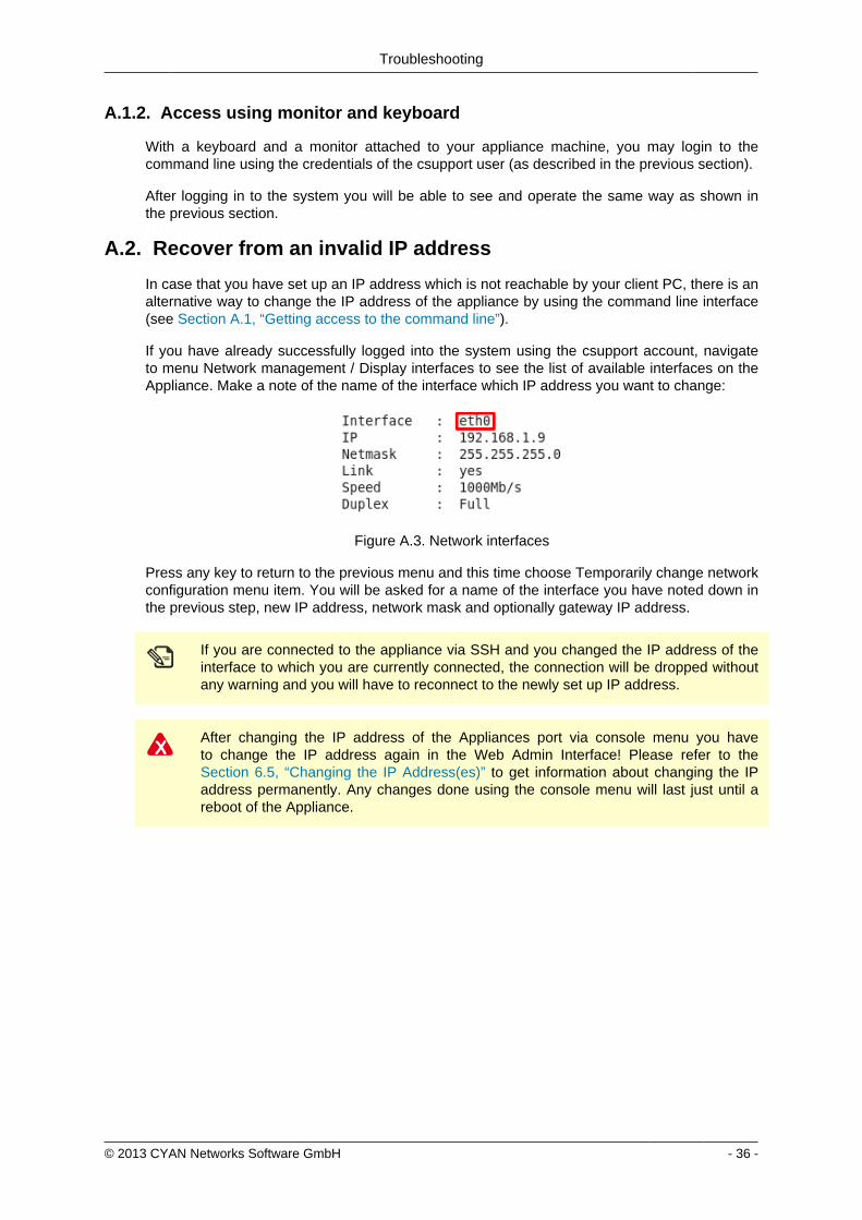
Troubleshooting
copy 2013 CYAN Networks Software GmbH - 36 -
A12 Access using monitor and keyboard
With a keyboard and a monitor attached to your appliance machine you may login to thecommand line using the credentials of the csupport user (as described in the previous section)
After logging in to the system you will be able to see and operate the same way as shown inthe previous section
A2 Recover from an invalid IP address
In case that you have set up an IP address which is not reachable by your client PC there is analternative way to change the IP address of the appliance by using the command line interface(see Section A1 ldquoGetting access to the command linerdquo)
If you have already successfully logged into the system using the csupport account navigateto menu Network management Display interfaces to see the list of available interfaces on theAppliance Make a note of the name of the interface which IP address you want to change
Figure A3 Network interfaces
Press any key to return to the previous menu and this time choose Temporarily change networkconfiguration menu item You will be asked for a name of the interface you have noted down inthe previous step new IP address network mask and optionally gateway IP address
If you are connected to the appliance via SSH and you changed the IP address of theinterface to which you are currently connected the connection will be dropped withoutany warning and you will have to reconnect to the newly set up IP address
After changing the IP address of the Appliances port via console menu you haveto change the IP address again in the Web Admin Interface Please refer to theSection 65 ldquoChanging the IP Address(es)rdquo to get information about changing the IPaddress permanently Any changes done using the console menu will last just until areboot of the Appliance
copy 2013 CYAN Networks Software GmbH - 37 -
Appendix B Contact data
B1 How to contact our sales department
Tel +43 (1) 33933-0
Email salescyan-networkscom
B2 How to contact our support department
Tel +43 (1) 33933-333
Email supportcyan-networkscom
B21 Getting Support
In case you should have any technical problems or questions and would like to get support fromour team we kindly ask you to provide us with the following information
bull Description of your question or problem
bull The version information of the product
bull The version information of Secure Web can be found after logging into the Web AdminInterface in the top part of the screen
Figure B1 Version information of the Secure Web
bull The version information of the Reporting System can be found after login in the top part ofthe screen of the Web Admin Interface
Figure B2 Version information of the Reporting System
bull All the information contained in the screen found in menu Services Services Overview
bull In the case authentication is activated provide us with the method in place (via Windows Agentvia Linux Agent etc)
bull The deployment method of the Appliance (Out-of-line In-Line DMZ)
bull The operation mode of the Appliance (dedicated mode transparent mode)
Contact data
copy 2013 CYAN Networks Software GmbH - 38 -
bull Information about the environment (proxy cascades that are used firewalls and gatewaysinvolved in the infrastructure that are of relevance to the Appliance)
The appliance interface provides the possibility to create a support package that includes theconfiguration and log files of the system This package can help us to track down the issue easierand faster Please attach this package to your e-mail
In order to create a support pack navigate to menu Appliances Maintenance Support and clickon the Download button You may select the files you want to provide to our support team andthen download a package which we kindly ask you to send to our support email address
Figure B3 Support Package
Further documentation about the product as well as technical white papers that describe certainuse cases can be found in our documentation repository on our homepage
httpwwwcyan-networkscomdocumentation