Embed Size (px)
Citation preview

GETTING STARTED
NI SMD-7611/7612 Stepper Drives and NI 9512 C Series Modules
Note If you are a new user of LabVIEW or are unfamiliar with LabVIEW, refer to the Getting Started with LabVIEW manual for information about LabVIEW and LabVIEW terminology.
This document explains how to install and configure the NI SMD-7611/7612 stepper drives for use with the NI 9512 C Series drive interface module.
ContentsWhat You Need to Get Started ................................................................................................. 2
Hardware .......................................................................................................................... 2Software............................................................................................................................ 3
Hardware Installation and Configuration ................................................................................. 4Step 1: Set Up the Real Time System............................................................................... 4Step 2: Connect the NI 9512 to the 37-Pin Terminal Block............................................. 4Step 3: Connect the 37-Pin Terminal Block to the +24 V Power Supply ........................ 5Step 4: Connect the Drive Command Signals .................................................................. 6Step 5: Connect the Drive Enable Signal ......................................................................... 6Step 6: (Optional) Connect the Drive Fault Signal........................................................... 7Step 7: (Optional) Connect the Encoder Signals .............................................................. 7Step 8: Connect the NI PS-12/13 Power Supply to the NI SMD-7611/7612................... 8Step 9: Connect the SMD-7611/7612 to the Motor.......................................................... 9Step 10: Configure the NI SMD-7611/7612 DIP Switches.............................................. 10Step 11: Set the Motor Selection Switch .......................................................................... 11Step 12: Power on the Drive and Verify Connections...................................................... 14
Software Installation and Configuration................................................................................... 14Step 1: Install Software on and Configure the NI RT Controller ..................................... 14Step 2: Create a Project and add NI RT Controller .......................................................... 15
A. CompactRIO Controller....................................................................................... 15B. EtherCAT Master and NI 9144 EtherCAT Expansion Chassis ........................... 16C. NI 9146/7/8/9 Ethernet RIO Expansion Chassis ................................................. 17
Step 3: Add a SoftMotion Axis to the Project .................................................................. 17Step 4: Configure the NI 9512 Axis ................................................................................. 19Step 5: Enable and Test the Drive Using LabVIEW ........................................................ 22
Where To Go From Here.......................................................................................................... 23Worldwide Support and Services ............................................................................................. 24

2 | ni.com | Getting Started with NI SMD-7611/7612 and NI 9512 Modules
What You Need to Get StartedYou need the following items to get started.
Hardware NI 9512 C Series stepper drive interface module
NI Real-Time controller– CompactRIO controller and chassis that support the RIO Scan Interface.
Tip To determine if your controller and chassis support the RIO Scan Interface go to ni.com/info and enter the Info Code rdsoftwareversion.
or– NI 9146, 9147, 9148, or 9149 Ethernet RIO Expansion Chassis.or– NI 9144 distributed chassis and compatible RT controller.
+24 V power supply (such as the NI PS-15) for the CompactRIO controller(NI part number 781093-01)
Separate +24 V power supply for the NI 9512 (such as the NI PS-15)
NI PS-12 or NI PS-13 power supply for the NI SMD-7611/7612
NI SMD-7611/7612 stepper drive
NI or third-party stepper motor
Note NI offers stepper motors matched to the NI SMD-7611/7612. Refer to ni.com/motion for motor options. National Instruments highly recommends using these motors for the best user experience.
(Optional) ENC-7740 encoder for ST17 motors (NI part number 748991-01) or ENC-7741 encoder for ST23 motors (NI part number 748992-01)
Encoder Cable to connect the encoder to the NI 951x terminal block (NI part number 783661-10)
Ethernet connection and cable for the CompactRIO controller
NI 951x Cable and Terminal Block bundle (NI part number 780553-01)

Getting Started with NI SMD-7611/7612 and NI 9512 Modules | © National Instruments | 3
Software LabVIEW 2010 (minimum).
LabVIEW 2010 Real-Time Module (minimum).
LabVIEW 2010 NI SoftMotion Module (minimum).
NI-RIO 3.5.1 (minimum).
Figure 1 shows a simplified connection diagram.
Figure 1. NI 9512 to NI SMD-7611/7612 Connections
1 2 3 4 5 6 7 8
EncoderConnections
+24 V Power Supply (NI PS-15 Shown)
NI RT Controller (NI cRIO-9014 shown)and NI 9512 Module
+24 V Power Supply (NI PS-15 Shown)
37-pin TerminalBlock
Ethernet Cable
I/O Connections
NI PS-12/13 Power Supply
LN-V+V
Made in China
+V ADJ
+
OUTPUT: 48V 6.7A INPUT: 100-240VAC 5A 50/60Hz
LN-V+V
Made in China
+V ADJ
+
.
NI Stepper Motor
NI SMD-7611/7612

4 | ni.com | Getting Started with NI SMD-7611/7612 and NI 9512 Modules
Hardware Installation and ConfigurationThis section covers the hardware setup for the Real Time system, NI 9512 C Series module, and NI SMD-7611/7612 stepper drive.
Step 1: Set Up the Real Time SystemComplete the following steps to set up the Real Time system depending on your hardware.1. Refer to the Getting Started guide included with the Real-Time controller to assemble it,
connect it to power, discover it on the network, and install the software in NI MAX.2. Install the NI 9512 module in an available slot that supports High Speed Interface (HSI) in
your chassis.
Note Older model chassis, such as cRIO-902x, cRIO-907x, cRIO-908x, NI 9144, and NI 9148, have HSI support on slots 1 through 4. Refer to your chassis documentation for more information about HSI slot support.
Step 2: Connect the NI 9512 to the 37-Pin Terminal Block1. Connect the MDR and DSUB connectors on the NI 951x Y-cable to the MDR and DSUB
connectors on the NI 9512 module. 2. Connect the 37-pin DSUB to the DSUB connector on the NI 951x terminal block.

Getting Started with NI SMD-7611/7612 and NI 9512 Modules | © National Instruments | 5
Figure 2 shows the 37-pin terminal block pin assignments.
Figure 2. NI 9512 37-Pin Terminal Block Pin Assignments
Step 3: Connect the 37-Pin Terminal Block to the +24 V Power Supply
Note Do not plug in or turn on the power supply until after you complete Step 12: Power on the Drive and Verify Connections.
1. Connect the V+ terminal from the 24 V power supply to one of the two Vsup inputs on the 37-pin terminal block. The 37-pin terminal block provides a Vsup input for the NI 9512 on pin 14 and pin 22.
2. Connect the V- terminal from the 24 V power supply to one of the COM terminals on the 37-pin terminal block. The 37-pin terminal block provides COM on pins 3, 5, 8, 17, 24, and 32.
3736
3534
3332
3130
2928
2726
2524
2322
2120
19
GN
D18
1716
1514
1312
1110
9 8
7 6
5 4
3 2
1
Forward Limit
Home
COM
Digital Input 0
COM
Encoder 0 Index+
Encoder 0 Index–
COM
+5V OUT
Position Compare
Reserved
Reserved
Digital Output 0†
Vsup†
Digital Input 1†
Direction (CCW)+†
COM†
Step (CW)+†
Shield
Digital Output 1†
Reverse Limit
Reserved
Vsup
Reserved
COM
Encoder 0 Phase A+
Encoder 0 Phase A–
Encoder 0 Phase B+
Position Capture
Encoder 0 Phase B–
Reserved
Reserved
COM†
Drive Enable†
Digital Input 3†
Digital Input 2†
Direction (CCW)–†
Step (CW)–†
† Indicates DSUB connector signals.

6 | ni.com | Getting Started with NI SMD-7611/7612 and NI 9512 Modules
Step 4: Connect the Drive Command SignalsComplete the following steps to connect the Drive Command signals to the NI 9512 terminal block.1. Connect the SMD-7611/7612 STEP+ and DIR+ terminals to the 37-pin terminal block +5V
OUT terminal (pin 9).2. Connect the SMD-7611/7612 STEP- terminal to the 37-pin terminal block Step (CW)+
terminal (pin 18).3. Connect the SMD-7611/7612 DIR- terminal to the 37-pin terminal block Direction
(CCW)+ terminal (pin 16).
Figure 3 shows the SMD-7611/7612 Drive Command and I/O Connector location and pinout.
Figure 3. SMD-7611/7612 Drive Command and I/O Connector
Step 5: Connect the Drive Enable SignalComplete the following steps to connect the Drive Enable signal, which controls the enable function of the drive:1. Connect the EN- terminal to the 37-pin terminal block COM terminal (pin 5).2. Connect the EN+ terminal to the 37-pin terminal block Drive Enable terminal (pin 33).
1 2 3 4 5 6 7 8
FAU
LT-
FAU
LT+
EN
-
EN
+
DIR
-
DIR
+
ST
EP
-
ST
EP
+

Getting Started with NI SMD-7611/7612 and NI 9512 Modules | © National Instruments | 7
Step 6: (Optional) Connect the Drive Fault SignalComplete the following steps to map an NI 9512 digital input to the SMD-7611/7612 fault output signal to monitor the NI SMD-7611/7612 stepper drive for faults:1. Connect the FAULT+ terminal to the 37-pin terminal block Vsup terminal (pin 22).2. Connect the FAULT- terminal to the 37-pin terminal block DI 0 terminal (pin 4).
Step 7: (Optional) Connect the Encoder SignalsIf your motor includes an encoder, complete the following steps to connect the encoder to the NI 951x terminal block:1. If an NI Encoder is being used, connect the appropriate end of the encoder cable
(NI part number 783661-10) to the encoder.2. Connect the encoder wires to the 37-pin terminal block as indicated in Table 1.3. Insulate any unused wires.
Table 1. NI SMD-7611/7612 to 37-Pin Terminal Block Connections
EncoderSignal Name
Encoder Cable Wire Color
37-Pin Terminal Block
Pin Number
37-Pin Terminal Block Signal Name
CH A blue 25 Encoder 0 Phase A+
CH A- blue/white 26 Encoder 0 Phase A-
CH B yellow 27 Encoder 0 Phase B+
CH B- yellow/white 29 Encoder 0 Phase B-
INDEX orange 6 Encoder 0 Index+
INDEX- orange/white 7 Encoder 0 Index-
GND black 8 COM
+Vcc red 9 +5V OUT

8 | ni.com | Getting Started with NI SMD-7611/7612 and NI 9512 Modules
Step 8: Connect the NI PS-12/13 Power Supply to the NI SMD-7611/7612
Note Do not plug in or turn on the power supply until after you complete Step 12: Power on the Drive and Verify Connections.
Complete the following steps to connect the power supply to AC input power and to the NI SMD-7611/7612. Figure 4 shows the power supply terminals.
Figure 4. NI PS-12/13 Power Supply Terminals
Figure 5 shows the SMD-7611/7612 Power and Motor Connector location and pinout.
Figure 5. SMD-7611/7612 Power and Motor Connector
1. Connect an AC input cable to the line, neutral, and protective earth connectors.2. Connect the SMD-7611/7612 V+ terminal to the power supply +V connector.3. Connect the SMD-7611/7612 V- terminal to the power supply -V connector.
1 +24 V (NI PS-12) or +48 V (NI PS-13) Output2 +24 V (NI PS-12) or +48 V (NI PS-13) Ground3 AC Input Ground (Protective Earth)
4 AC Input Neutral5 AC Input Line
LN-V+V
Made in China
+V ADJ
+
OUTPUT: 48V 6.7A INPUT: 100-240VAC 5A 50/60Hz
LN-V+V
Made in China
+V ADJ
+
Serial No.
1 2 3 4 5
1 2 3 4 5 6 7 8
V+ V- A+ A- B-B+
GroundScrew

Getting Started with NI SMD-7611/7612 and NI 9512 Modules | © National Instruments | 9
4. Connect the SMD-7611/7612 green ground screw to earth ground.5. Connect the NI 9512 COM to the NI PS-12/13 -V terminal to ensure a common reference.
Note Refer to the NI SMD-7611/7612 User Manual for more information about connecting the power supply.
Step 9: Connect the SMD-7611/7612 to the MotorNI offers stepper motors matched to the SMD-7611/7612. The ST24-1, ST24-2,and ST24-3 are four lead motors. Connect them as shown in Figure 6.
Figure 6. Four Lead Motor Connection
The ST17-1, ST17-2, ST17-3, ST17-4,ST23-1, ST23-4, ST23-6, ST23-8, ST34-4, ST34-8 are eight lead motors that are connected using a parallel configuration. Connect them as shown in Figure 7.
Figure 7. Eight Lead Motor Parallel Connection
When using the SMD-7612, connect the ST34-1, ST34-2, and ST34-5 using a parallel configuration as shown in Figure 7.
A+
A–
B+ B–
4
Lead
Motor
Red
Blue
Yellow White
A+
A–
B+ B–
8
Lead
Motor
Orange
Org/Wht
Blk/Wht
Black
Red
Red/WhtYel/Wht
Yellow

10 | ni.com | Getting Started with NI SMD-7611/7612 and NI 9512 Modules
When using the SMD-7611, connect the ST34-1, ST34-2, and ST34-5 using a series configuration as shown in Figure 8.
Figure 8. Eight Lead Motor Series Connection
Step 10: Configure the NI SMD-7611/7612 DIP SwitchesThe NI SMD-7611/7612 provides drive configuration DIP switches. Refer to the NI SMD-7611/7612 User Manual for more information about the DIP switch options. The following figure shows the DIP switch location and functions.
Note If you change the DIP switch settings you must power cycle the NI SMD-7611/7612 for the new settings to take effect.
Figure 9. NI SMD-7611/7612 DIP Switches
A+
A–
B+ B–
8
Lead
Motor
Orange
Org/Wht
Blk/Wht
Black
Red Red/Wht
Yel/Wht
Yellow
1 2 3 4 5 6 7 8
Run Current12
34
56
78
Step Size
Idle CurrentLoad Inertia
Self Test

Getting Started with NI SMD-7611/7612 and NI 9512 Modules | © National Instruments | 11
Refer to Table 2 for the DIP switch settings that this document uses.
Step 11: Set the Motor Selection SwitchNational Instruments offers stepper motors matched to the NI SMD-7611/7612. National Instruments highly recommends using these motors for the best user experience. Figure 10 shows the Motor Selection Switch location.
Figure 10. NI SMD-7611/7612 Motor Selection Switch
Table 2. DIP Switch Settings
Setting Name Switch Position Corresponding Value
Running Current 100%
Load Inertia 0 - 4X
Idle Current 50%
Steps/rev 2000
Self Test Off
1 2
3
4
5 6 7
8
1 2 3 4 5 6 7 8
Motor SelectionSwitch

12 | ni.com | Getting Started with NI SMD-7611/7612 and NI 9512 Modules
Tables 3 and 4 show the switch settings for compatible stepper motors for the SMD-7611 and SMD-7612, respectively. If you are using a motor not in the list, set the switch to a motor with a rotor inertia, holding torque, and current that are within 10% of your motor.
Table 3. NI SMD-7611 Motor Selection Switch Settings
Switch Setting Motor Wiring
Drive Current Amps, peak of
sine
Holding Torque, (oz-in)
Rotor Inertia (g-cm2)
0reserved for custom configurations
1
2 ST17-4 parallel 2.4 113 123
3 ST17-1 parallel 1.6 31.4 35
4 ST17-2 parallel 2 51 54
5 ST17-3 parallel 2 62.8 68
6 ST23-1 parallel 3.4 76.6 120
7 ST23-4 parallel 4.5 159.3 300
8 ST23-6 parallel 4.5 237.6 480
9 ST24-1 4 leads 3.36 123 280
A ST24-2 4 leads 4.5 166 450
B ST24-3 4 leads 4.5 332 900
C ST34-2 series 4.5 585 1400
D ST34-5 series 4.5 1113 2680
E ST34-1 series 3.816 396 1100

Getting Started with NI SMD-7611/7612 and NI 9512 Modules | © National Instruments | 13
Table 4. NI SMD-7612 Motor Selection Switch Settings
Switch Setting Motor Wiring
Drive Current Amps, peak of
sine
Holding Torque,
oz-in
Rotor Inertia g-cm2
0
reserved for custom configurations1
2
3 ST23-8 parallel 6 354 750
4 ST23-1 parallel 3.4 76.6 120
5 ST23-4 parallel 5 177 300
6 ST23-6 parallel 5 264 480
7 ST24-1 4 leads 3.36 123 280
8 ST24-2 4 leads 4.8 177 450
9 ST24-3 4 leads 4.8 354 900
A ST34-2 parallel 8 507 1400
B ST34-5 parallel 8 965 2680
C ST34-8 parallel 8 1439 4000
D ST34-1 parallel 7.56 396 1100
E ST34-4 parallel 7.56 849 1850

14 | ni.com | Getting Started with NI SMD-7611/7612 and NI 9512 Modules
Step 12: Power on the Drive and Verify ConnectionsAfter all hardware connections have been made complete the following steps to confirm the hardware setup.1. Turn on all power supplies.2. Verify that the Drive Status LED on the NI SMD-7611/7612 flashes or is solid green.
Figure 11 shows the location of the Drive Status LED.
Figure 11. Drive Status LED Location
If the Drive Status LED does not flash or turn solid green, turn off all power, verify the connections, and try again. Refer to the Worldwide Support and Services section for additional tips.
Software Installation and ConfigurationThis section covers installing and configuring software for the NI 9512 C Series module.
Note These instructions assume you have installed all required software from the What You Need to Get Started section on your development machine.
Step 1: Install Software on and Configure the NI RT ControllerComplete the following steps to configure the controller and install software on it.1. Launch Measurement & Automation Explorer (MAX) on the development computer by
clicking the MAX icon on the desktop, or by selecting Start»All Programs»National Instruments»NI MAX.
2. Select the controller under Remote Systems in the Configuration pane. If you do not see the controller, you may need to disable the firewall on the development computer.
3. Verify that the Serial Number in the Identification section matches the serial number on the device.
4. Expand the controller item in the tree, right-click Software, and select Add/Remove Software.
5. Select a recommended software set that includes NI-RIO 3.5.1 (minimum) with NI Scan Engine Support.
1 2 3 4 5 6 7 8
Status LEDs

Getting Started with NI SMD-7611/7612 and NI 9512 Modules | © National Instruments | 15
6. Click Next and enable the following add-ons:• LabVIEW SoftMotion Module• NI Industrial Communications for EtherCAT if using the NI 9144.
7. Click Next to install the selected software on the controller. Click Help if you need information about installing recommended software sets.
8. Close MAX.
Step 2: Create a Project and add NI RT ControllerComplete the following steps to create a LabVIEW project.1. Launch LabVIEW by selecting Start»All Programs»National Instruments»LabVIEW.2. Click the Empty Project link in the Getting Started window to display the Project
Explorer window. You can also select File»New Project to display the Project Explorer window.
3. Select Help and make sure that Show Context Help is checked. You can refer to the context help throughout the tutorial for information about items on the block diagram.
Depending on the hardware configuration being used, continue to the following respective sections.
A. CompactRIO ControllerIf you are using a CompactRIO controller, complete the following steps to add the device to the project and detect the C Series modules.1. Right-click the top-level project item in the Project Explorer window and select New»
Targets and Devices from the shortcut menu to display the Add Targets and Devices dialog box.
2. Make sure that the Existing target or device radio button is selected.3. Expand Real-Time CompactRIO.4. Select the CompactRIO controller to add to the project and click OK.5. If you have LabVIEW FPGA installed, the Select Programming Mode dialog box
appears. Select Scan Interface to put the system into Scan Interface mode.
Tip Use the CompactRIO Chassis Properties dialog box to change the programming mode in an existing project. Right-click the CompactRIO chassis in the Project Explorer window and select Properties from the shortcut menu to display this dialog box.
6. Click Discover in the Discover C Series Modules? dialog box if it appears.7. Click Continue.8. Right-click the controller item in the Project Explorer window and select Properties from
the shortcut menu to display the RT Target Properties dialog box. Select Scan Engine from the Category list to display the Scan Engine page.
16 | ni.com | Getting Started with NI SMD-7611/7612 and NI 9512 Modules
9. Set the Scan Period to 5 ms or lower.10. Click OK to close the RT Target Properties dialog box.
B. EtherCAT Master and NI 9144 EtherCAT Expansion ChassisIf you are using the NI 9144 chassis, complete the following steps to add the EtherCAT master device and detect the C Series module.1. Add the Master Real Time Controller to the project. Right click the top level project item
in the Project Explorer window and select New»Targets and Devices from the shortcut menu to display the Add Targets and Devices dialog box.
2. Make sure that Existing target or device radio button is selected.3. Expand the folder that corresponds to the device you are adding, such as Real Time
Industrial Controller, Real Time PXI, and so on.4. Select Real Time to add to the project and click OK.5. In the LabVIEW Project Explorer window, right-click the master controller and select
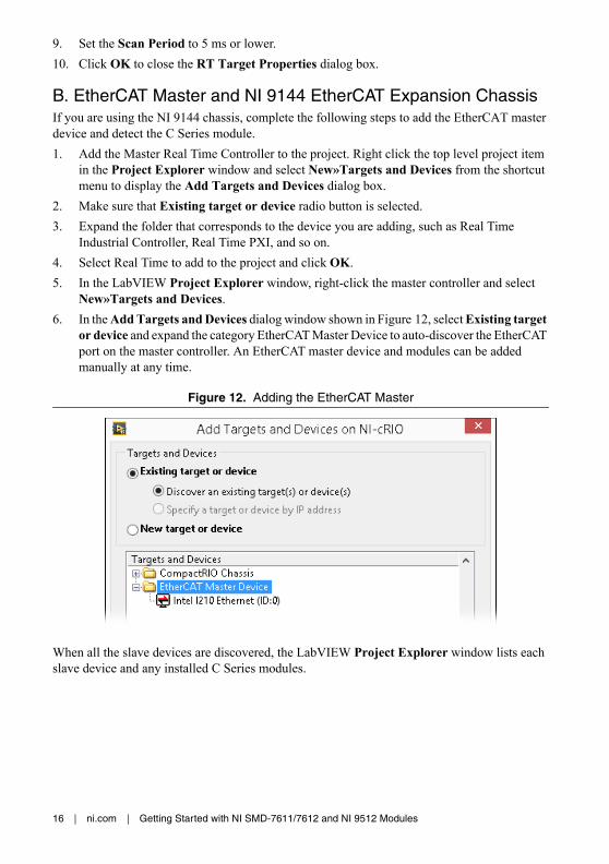
New»Targets and Devices.6. In the Add Targets and Devices dialog window shown in Figure 12, select Existing target
or device and expand the category EtherCAT Master Device to auto-discover the EtherCAT port on the master controller. An EtherCAT master device and modules can be added manually at any time.
Figure 12. Adding the EtherCAT Master
When all the slave devices are discovered, the LabVIEW Project Explorer window lists each slave device and any installed C Series modules.

Getting Started with NI SMD-7611/7612 and NI 9512 Modules | © National Instruments | 17
C. NI 9146/7/8/9 Ethernet RIO Expansion ChassisComplete the following steps to add the device to the project and detect the C Series modules if the NI 9146/7/8/9 Ethernet RIO Expansion chassis is being used.1. Right-click the top-level project item in the Project Explorer window and select New»
Targets and Devices from the shortcut menu to display the Add Targets and Devices dialog box.
2. Make sure that the Existing target or device radio button is selected.3. Expand Ethernet RIO.4. Select the Ethernet RIO expansion chassis to add to the project and click OK.5. If you have LabVIEW FPGA installed, the Select Programming Mode dialog box
appears. Select Scan Interface to put the system into Scan Interface mode.
Tip Use the Chassis Properties dialog box to change the programming mode in an existing project. Right-click the chassis in the Project Explorer window and select Properties from the shortcut menu to display this dialog box.
6. Click Discover in the Discover C Series Modules? dialog box if it appears.7. Click Continue.8. Right-click the controller item in the Project Explorer window and select Properties from
the shortcut menu to display the Ethernet RIO Properties dialog box. Select Scan Engine from the Category list to display the Scan Engine page.
9. Set the Scan Period to 5 ms or lower. 10. Click OK to close the Ethernet RIO Properties dialog box.
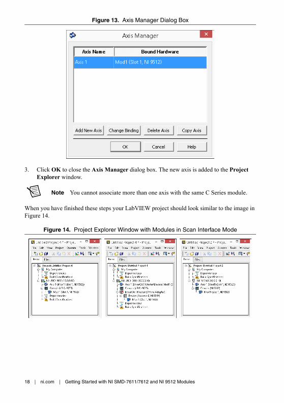
Step 3: Add a SoftMotion Axis to the ProjectComplete the following steps to create a LabVIEW project and add a SoftMotion Axis to it.1. Right-click the controller item in the Project Explorer window and select New»
NI SoftMotion Axis from the shortcut menu to open the Axis Manager dialog box, shown in Figure 7.
2. Click Add New Axis to create an NI SoftMotion axis associated with the NI 9512 module. Axes are automatically bound to an available module. You can double-click the axis name to rename the axis and give it a descriptive name.
18 | ni.com | Getting Started with NI SMD-7611/7612 and NI 9512 Modules
Figure 13. Axis Manager Dialog Box
3. Click OK to close the Axis Manager dialog box. The new axis is added to the Project Explorer window.
Note You cannot associate more than one axis with the same C Series module.
When you have finished these steps your LabVIEW project should look similar to the image in Figure 14.
Figure 14. Project Explorer Window with Modules in Scan Interface Mode

Getting Started with NI SMD-7611/7612 and NI 9512 Modules | © National Instruments | 19
Step 4: Configure the NI 9512 AxisThe Axis Configuration dialog box includes configuration options for stepper drive command signals, feedback devices, motion and digital I/O, trajectory, and axis setup. Figure 15 shows the parts of the Axis Configuration dialog box for the NI 9512 C Series module. Refer to the NI SoftMotion Module book of the LabVIEW Help for detailed information about each configuration option.
Figure 15. Axis Configuration Dialog Box
Note The Axis Configuration dialog box user interface may not match this image exactly depending on which version of the LabVIEW NI SoftMotion Module you are using.

20 | ni.com | Getting Started with NI SMD-7611/7612 and NI 9512 Modules
Complete the following steps to configure the axis I/O settings for use with the NI SMD-7611/7612 stepper drive.1. Right-click the axis in the Project Explorer window and select Properties from the
shortcut menu to open the Axis Configuration dialog box.2. Configure the following settings on the General Settings page ( ).
a. Confirm that Loop Mode is set to Open-Loop. Axes configured in open-loop mode produce step outputs but do not require feedback from the motor to verify position.
b. Set Feedback Source to Encoder 0, if you have connected an encoder, or None if you do not have an encoder connected.
c. Confirm that the Axis Enabled and Enable Drive on Transition to Active Mode checkboxes contain checkmarks. These selections configure the axes to automatically activate when the NI Scan Engine switches to Active mode.
Note Disable these options to prevent axes from automatically activating when the NI Scan Engine switches to Active mode.
3. If you have connected an encoder, click the Encoder button ( ) and configure the Units and Counts Per Unit.a. In the Active State section set the Line State for A, B, and Index to High.b. In the Index Reference Criteria section set the Line State for A and B to Inactive.c. Select rev from the Units text box, or type revolutions if you prefer.d. Set the Counts per rev to 8,000. This setting is the encoder resolution in quadrature
counts per revolution and corresponds to the encoder lines per revolution multiplied by four.
Note The counts per revolution should be set accordingly if a dual shaft motor with a third party Encoder is being used.
When you are finished the Encoder Settings page will look similar to Figure 16.
Figure 16. Axis Configuration Encoder Page
Getting Started with NI SMD-7611/7612 and NI 9512 Modules | © National Instruments | 21
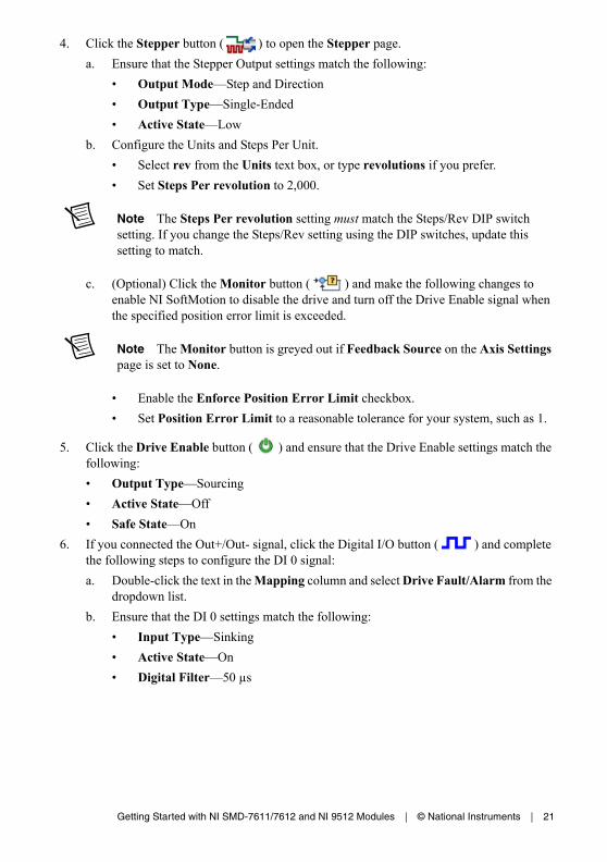
4. Click the Stepper button ( ) to open the Stepper page.a. Ensure that the Stepper Output settings match the following:
• Output Mode—Step and Direction• Output Type—Single-Ended• Active State—Low
b. Configure the Units and Steps Per Unit.• Select rev from the Units text box, or type revolutions if you prefer.• Set Steps Per revolution to 2,000.
Note The Steps Per revolution setting must match the Steps/Rev DIP switch setting. If you change the Steps/Rev setting using the DIP switches, update this setting to match.
c. (Optional) Click the Monitor button ( ) and make the following changes to enable NI SoftMotion to disable the drive and turn off the Drive Enable signal when the specified position error limit is exceeded.
Note The Monitor button is greyed out if Feedback Source on the Axis Settings page is set to None.
• Enable the Enforce Position Error Limit checkbox.• Set Position Error Limit to a reasonable tolerance for your system, such as 1.
5. Click the Drive Enable button ( ) and ensure that the Drive Enable settings match the following:• Output Type—Sourcing• Active State—Off• Safe State—On
6. If you connected the Out+/Out- signal, click the Digital I/O button ( ) and complete the following steps to configure the DI 0 signal:a. Double-click the text in the Mapping column and select Drive Fault/Alarm from the
dropdown list. b. Ensure that the DI 0 settings match the following:
• Input Type—Sinking• Active State—On• Digital Filter—50 µs

22 | ni.com | Getting Started with NI SMD-7611/7612 and NI 9512 Modules
7. Complete the following additional steps if you do not have limits and home connected at this time:a. Click the Limits & Home button ( ).b. In the Forward Limit and Reverse Limit sections ensure that the settings match the
following:
Note These configuration settings disable limits for initial setup and testing purposes. National Instruments recommends connecting and enabling limits in your final application.
• Clear the Enable checkbox from both Forward Limit and Reverse Limit. • Set the Active State for both Forward Limit and Reverse Limit to Off. This
prevents a limit warning even though limits are turned off.c. Open the Home section and clear the Enable checkbox.
8. Configure any additional I/O settings according to your system requirements, such as position compare or position capture signals.
9. Click OK to close the Axis Configuration dialog box.10. Right-click the controller item in the Project Explorer window and select Deploy All to
deploy the axis information.11. Select File»Save Project to save the project.
Step 5: Enable and Test the Drive Using LabVIEWUse the Interactive Test Panel to test and debug your motion system and configuration settings on the selected axis. With the Interactive Test Panel you can perform a simple straight-line move and monitor feedback position and position error information, move and I/O status information, change move constraints, get information about software errors and faults, and view position or velocity plots of the move.
Complete the following steps to test your setup after configuring the axis using the Axis Configuration dialog box.1. Right-click the axis in the Project Explorer window and select Interactive Test Panel
from the shortcut menu. Opening this dialog box sends the axis settings to the hardware and activates the I/O on the module.
2. On the Move tab set Move Mode to Relative Position and Target Position to 20 rev.3. On the Move Constraints tab set Velocity to 2 rev/sec, Acceleration and Deceleration to
20 rev/sec2, and Acceleration Jerk and Deceleration Jerk to 200 rev/sec3. Using the encoder counts per revolution and stepper steps per revolution values specified in this tutorial the motor will move 20 revolutions at 120 rpm.
Tip Click the Help button ( ) on the bottom of the dialog box for detailed information about the items available in this dialog box.

Getting Started with NI SMD-7611/7612 and NI 9512 Modules | © National Instruments | 23
4. Click the Enable button ( ) on the bottom of the dialog box to enable the drive.5. Click the Start button ( ) on the bottom of the dialog box to start the move with the
configured options.6. Use the Status and Plots tabs to monitor the move while it is in progress.
Finalize your motion system setup by connecting and configuring additional I/O such as limits as required by your system using the 37-pin terminal block.
Where To Go From HereThe following documents contain additional information that you may find helpful. All referenced documents ship with the product and are available at ni.com/manuals.• Operating instructions for the controller and C Series module.• NI SMD-7611/7612 User Manual• LabVIEW NI SoftMotion Module Help—Use this help file to learn about using the
NI SoftMotion Module in LabVIEW including information about function blocks and using the NI SoftMotion Module with the LabVIEW Project. To access this help file from LabVIEW, select Help»LabVIEW Help, then expand the LabVIEW NI SoftMotion Module book on the Contents tab.
• LabVIEW Help—Use the LabVIEW Help to access information about LabVIEW programming concepts, step-by-step instructions for using LabVIEW, and reference information about LabVIEW VIs, functions, palettes, menus, tools, properties, methods, events, dialog boxes, and so on. The LabVIEW Help also lists the LabVIEW documentation resources available from National Instruments. Access the LabVIEW Help by selecting Help»LabVIEW Help.
• SoftMotion Examples—After the configuration and testing of the motion system is complete, use SoftMotion API to program the motion control application in LabVIEW. Access the SoftMotion Examples by selecting Help»Find Examples»Hardware Input and Output»Motion Control»SoftMotion.

© 2016 National Instruments. All rights reserved.
376094B-01 Dec16
Refer to the NI Trademarks and Logo Guidelines at ni.com/trademarks for more information on NI trademarks. Other product and company names mentioned herein are trademarks or trade names of their respective companies. For patents covering NI products/technology, refer to the appropriate location: Help»Patents in your software, the patents.txt file on your media, or the National Instruments Patents Notice at ni.com/patents. You can find information about end-user license agreements (EULAs) and third-party legal notices in the readme file for your NI product. Refer to the Export Compliance Information at ni.com/legal/export-compliance for the NI global trade compliance policy and how to obtain relevant HTS codes, ECCNs, and other import/export data. NI MAKES NO EXPRESS OR IMPLIED WARRANTIES AS TO THE ACCURACY OF THE INFORMATION CONTAINED HEREIN AND SHALL NOT BE LIABLE FOR ANY ERRORS. U.S. Government Customers: The data contained in this manual was developed at private expense and is subject to the applicable limited rights and restricted data rights as set forth in FAR 52.227-14, DFAR 252.227-7014, and DFAR 252.227-7015.
Worldwide Support and ServicesThe National Instruments Web site is your complete resource for technical support. At ni.com/support you have access to everything from troubleshooting and application development self-help resources to email and phone assistance from NI Application Engineers.
Visit ni.com/services for NI Factory Installation Services, repairs, extended warranty, calibration, and other services.
Visit ni.com/register to register your National Instruments product. Product registration facilitates technical support and ensures that you receive important information updates from NI.
A Declaration of Conformity (DoC) is our claim of compliance with the Council of the European Communities using the manufacturer’s declaration of conformity. This system affords the user protection for electromagnetic compatibility (EMC) and product safety. You can obtain the DoC for your product by visiting ni.com/certification. If your product supports calibration, you can obtain the calibration certificate for your product at ni.com/calibration.
National Instruments corporate headquarters is located at 11500 North Mopac Expressway, Austin, Texas, 78759-3504. National Instruments also has offices located around the world to help address your support needs. For telephone support in the United States, create your service request at ni.com/support and follow the calling instructions or dial 512 795 8248. For telephone support outside the United States, visit the Worldwide Offices section of ni.com/niglobal to access the branch office Web sites, which provide up-to-date contact information, support phone numbers, email addresses, and current events.