Embed Size (px)
Citation preview

INDEXInstrumentation Cables
- Pairs and Triads (600V*)........................................... 2 - 3
Power and Control Cables- Multi-conductor w/ Bare Ground(s) (600V*)............. 4 - 5
Composite Power andControl Cables
- Multi-conductor w/ Bare Ground (600V*) ................. 6 - 7
Power Cables- 600V* 3 and 4 Conductors with Bare Ground(s) ...... 8 - 9
Medium Voltage Cables- 5kV - 133% Insulation Levels.................................10 - 11- 8kV - 100% Insulation Level...................................10 - 11- 15kV - 100% & 133% Insulation Levels.................12 - 13
Pulling Instructions ......................................................14
Pulling Tension Tables ................................................15
Conductor ID ...................................................................16
*600V/1000V Marine Shipboard Cable
Nexans AmerCable believes the information presented throughout this catalog to be reliable and current. All information is subject to change without notice. The informationlisted is approximate, and is presented only as a guide for product selection. We make no claims or warranties for the suitability of any product for any particular application.
Nexans AmerCable and CORFLEX are registered trademarks of Nexans © 2014, AmerCable Incorporated
Flame RetardantAll CORFLEX cables pass
UL 1685 and IEEE 383vertical tray fire tests at
70,000 BTU/hr, IEC60332-3 category A fire test, IEEE 1202
and CSA FT4.
CORFLEX rated less than5 kV also passes ICEAT-29-520 fire test at
210,000 BTU/hr.
ArmorContinuous corrugatedand welded, impervious
aluminum sheathwith no more than0.2% trace copperprovides completeprotection against
liquid and gas ingress.
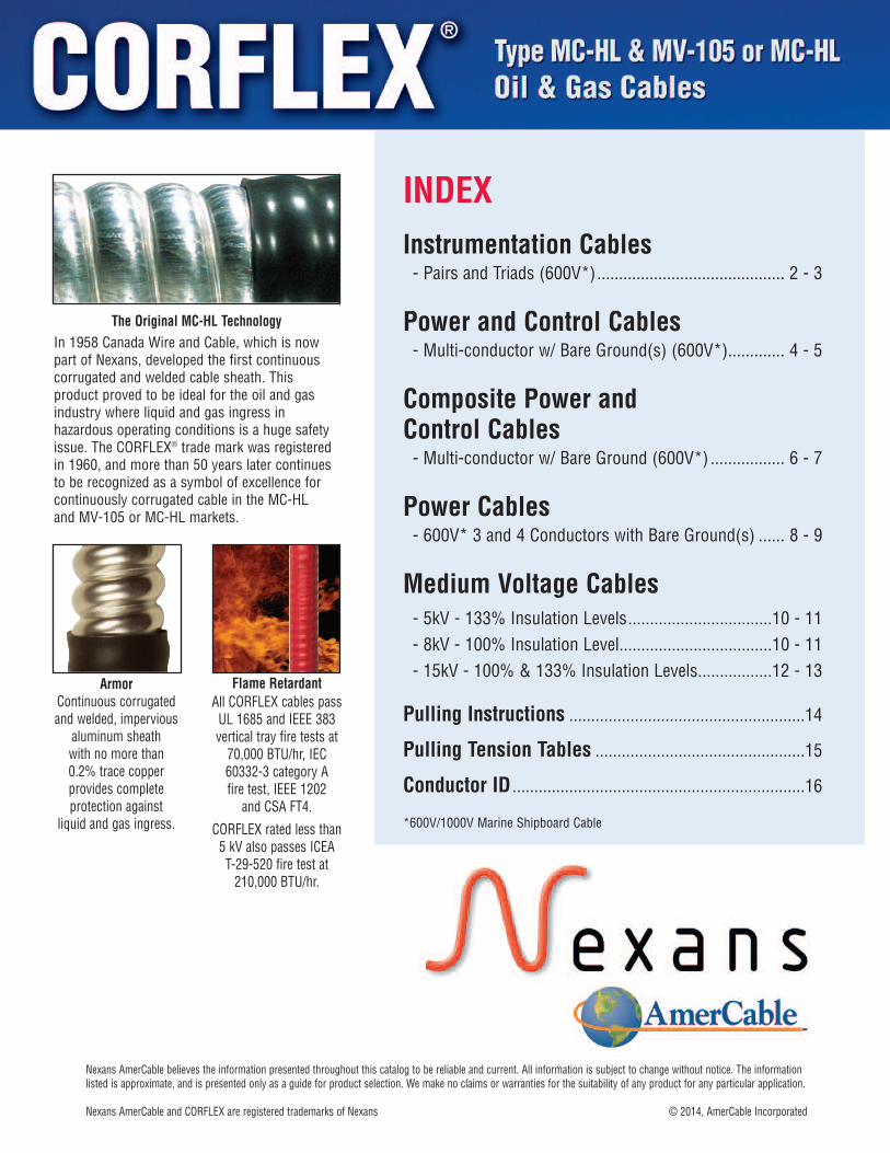
The Original MC-HL TechnologyIn 1958 Canada Wire and Cable, which is nowpart of Nexans, developed the first continuouscorrugated and welded cable sheath. Thisproduct proved to be ideal for the oil and gasindustry where liquid and gas ingress inhazardous operating conditions is a huge safetyissue. The CORFLEX® trade mark was registeredin 1960, and more than 50 years later continuesto be recognized as a symbol of excellence forcontinuously corrugated cable in the MC-HL and MV-105 or MC-HL markets.
1
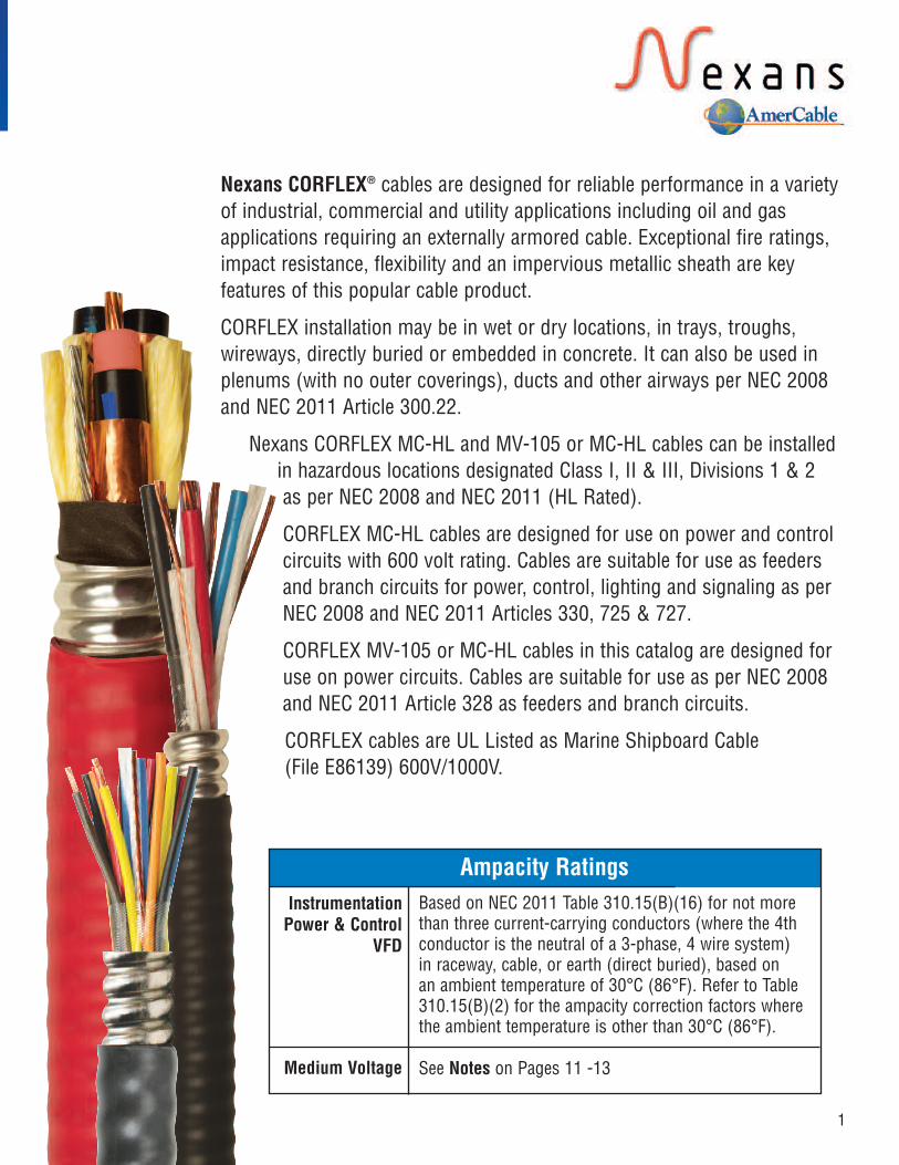
Nexans CORFLEX® cables are designed for reliable performance in a varietyof industrial, commercial and utility applications including oil and gasapplications requiring an externally armored cable. Exceptional fire ratings,impact resistance, flexibility and an impervious metallic sheath are keyfeatures of this popular cable product.
CORFLEX installation may be in wet or dry locations, in trays, troughs,wireways, directly buried or embedded in concrete. It can also be used inplenums (with no outer coverings), ducts and other airways per NEC 2008and NEC 2011 Article 300.22.
Nexans CORFLEX MC-HL and MV-105 or MC-HL cables can be installedin hazardous locations designated Class I, II & III, Divisions 1 & 2as per NEC 2008 and NEC 2011 (HL Rated).
CORFLEX MC-HL cables are designed for use on power and controlcircuits with 600 volt rating. Cables are suitable for use as feedersand branch circuits for power, control, lighting and signaling as perNEC 2008 and NEC 2011 Articles 330, 725 & 727.
CORFLEX MV-105 or MC-HL cables in this catalog are designed foruse on power circuits. Cables are suitable for use as per NEC 2008and NEC 2011 Article 328 as feeders and branch circuits.
CORFLEX cables are UL Listed as Marine Shipboard Cable (File E86139) 600V/1000V.
Ampacity RatingsInstrumentationPower & Control
VFD
Medium Voltage
Based on NEC 2011 Table 310.15(B)(16) for not morethan three current-carrying conductors (where the 4thconductor is the neutral of a 3-phase, 4 wire system)in raceway, cable, or earth (direct buried), based onan ambient temperature of 30°C (86°F). Refer to Table310.15(B)(2) for the ampacity correction factors wherethe ambient temperature is other than 30°C (86°F).
See Notes on Pages 11 -13
CORFLEX® is a registered trademark of Nexans
2 www. nexansamercable.com • e-mail: [email protected]
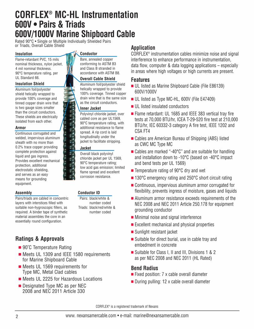
CORFLEX® MC-HL Instrumentation600V • Pairs & Triads600V/1000V Marine Shipboard CableRated 90°C • Single or Multiple Individually Shielded Pairs or Triads, Overall Cable Shield
Ratings & Approvals 90˚C Temperature Rating Meets UL 1309 and IEEE 1580 requirements
for Marine Shipboard Cable Meets UL 1569 requirements for
Type MC, Metal Clad cables Meets UL 2225 for Hazardous Locations Designated Type MC as per NEC
2008 and NEC 2011 Article 330
ApplicationCORFLEX® instrumentation cables minimize noise and signalinterference to enhance performance in instrumentation,data flow, computer & data logging applications – especiallyin areas where high voltages or high currents are present.
Features UL listed as Marine Shipboard Cable (File E86139)
600V/1000V UL listed as Type MC-HL, 600V (File E47409) UL listed insulated conductors Flame retardant: UL 1685 and IEEE 383 vertical tray fire
tests at 70,000 BTU/hr, ICEA T-29-520 fire test at 210,000BTU/hr, IEC 60332-3 category A fire test, IEEE 1202 andCSA FT4
Cables are American Bureau of Shipping (ABS) listedas CWC MC Type MC
Cables are marked “-40°C” and are suitable for handlingand installation down to -10°C (based on -40°C impactand bend tests per UL 1569)
Temperature rating of 90°C dry and wet 130°C emergency rating and 250°C short circuit rating Continuous, impervious aluminum armor corrugated for
flexibility, prevents ingress of moisture, gases and liquids Aluminum armor resistance exceeds requirements of the
NEC 2008 and NEC 2011 Article 250.178 for equipmentgrounding conductor
Minimal noise and signal interference Excellent mechanical and physical properties Sunlight resistant jacket Suitable for direct burial, use in cable tray and
embedment in concrete Suitable for Class I, II and III, Divisions 1 & 2
as per NEC 2008 and NEC 2011 (HL Rated)
Bend Radius Fixed position: 7 x cable overall diameter During pulling: 12 x cable overall diameter
ConductorBare, annealed copperconforming to ASTM B3 and Class B stranded inaccordance with ASTM B8.
AssemblyPairs/triads are cabled in concentriclayers with interstices filled withsuitable non-hygroscopic fillers, asrequired. A binder tape of syntheticmaterial assembles the core in anessentially round configuration.
Conductor IDPairs: black/white &
number codedTriads: black/red/white &
number coded
ArmorContinuous corrugated andwelded, impervious aluminumsheath with no more than0.2% trace copper providingcomplete protection againstliquid and gas ingress.Provides excellent mechanicalprotection, additionalelectrostatic shielding,and serves as an easymeans for groundingequipment.
InsulationFlame-retardant PVC, 15 milsnominal thickness, nylon jacket,4 mil nominal thickness. 90°C temperature rating, per UL Standard 66.
Insulation ShieldAluminum foil/polyestershield helically wrapped toprovide 100% coverage andtinned copper drain wire thatis two gauge sizes smallerthan the circuit conductors.These shields are electricallyisolated from each other.
Overall Cable ShieldAluminum foil/polyester shieldhelically wrapped to provide100% coverage. Tinned copperdrain wire that is the same sizeas the circuit conductors.
JacketOverall black polyvinylchloride jacket per UL 1569,90°C temperature rating; low acid gas emission; limitedflame spread and excellentcorrosion resistance.
Inner JacketPolyvinyl chloride jacket, overcabled core as per UL1569,90°C temperature rating, withadditional resistance to flamespread. A rip cord is laidlongitudinally under thejacket to facilitate stripping.

3800-506-9473 • 713-896-5800 • Fax: 713-849-9009
NexansDesignNo.
654988654921654947654962665250662116
No.of
Pairs248121624
(inches)0.3190.3800.5170.6470.7311.016
(mils)404050505050
(inches)0.4050.4650.6210.7530.8371.124
(inches)0.5940.6330.8360.9761.1421.420
(mils)505050505050
(inches)0.6990.7350.9401.0801.2471.525
(lb/kft)2182573736218171427
Inner JacketThickness
Nominal DiameterOver Inner Jacket
Nominal DiameterOver Armor
Outer JacketThicknessPVC
(mils)151515151515
Nylon(mils)
444444
Insulation Thickness Nominal DiameterOver Outer Jacket
Approx. NetCable Weight
Nominal DiameterOver Core
Pairs with Individual and Overall Shield • 600V – 18 AWG (7w)600V/1000V Marine Shipboard Cable
Pairs with Individual and Overall Shield • 600V – 16 AWG (7w)600V/1000V Marine Shipboard Cable
Triads with Individual and Overall Shield • 600V – 16 AWG (7w)600V/1000V Marine Shipboard Cable
Electrical Properties –Pairs/Triads with Individual and Overall Cable Shield
Conductor Size(AWG)
DC Resistance(ohms/kft @ 20°C)
Conductor–Conductor(pf/ft)
Pairs
Capacitance
Triads
Conductor–Shield(pf/ft)
Conductor–Conductor(pf/ft)
Conductor–Shield(pf/ft)
1816
6.644.18
7486
148172
6387
156180
NexansDesignNo.
645390659052645291659078650796654889654905650788
No.of
Pairs1248
12162436
(inches)0.2090.4240.4820.6350.7970.8821.1241.312
(mils)4040505050505050
(inches)0.2930.4770.5330.6760.8350.9831.1261.370
(inches)0.4920.6390.7670.9261.1401.3201.4221.746
(mils)5050505050505060
(inches)0.6050.7440.8711.0301.2461.4311.5261.879
(lb/kft)157216375604862115114322121
Inner JacketThickness
Nominal DiameterOver Inner Jacket
Nominal DiameterOver Armor
Outer JacketThicknessPVC
(mils)1515151515151515
Nylon(mils)
44444444
Insulation Thickness Nominal DiameterOver Outer Jacket
Approx. NetCable Weight
Nominal DiameterOver Core
NexansDesignNo.
654863644344670083670067
No.of
Triads148
12
(inches)0.2250.4840.6800.820
(mils)40505050
(inches)0.3040.5870.7860.925
(inches)0.5070.7980.9981.212
(mils)50505050
(inches)0.6190.9001.1021.317
(lb/kft)1713004671007
Inner JacketThickness
Nominal DiameterOver Inner Jacket
Nominal DiameterOver Armor
Outer JacketThicknessPVC
(mils)15151515
Nylon(mils)
4444
Insulation Thickness Nominal DiameterOver Outer Jacket
Approx. NetCable Weight
Nominal DiameterOver Core
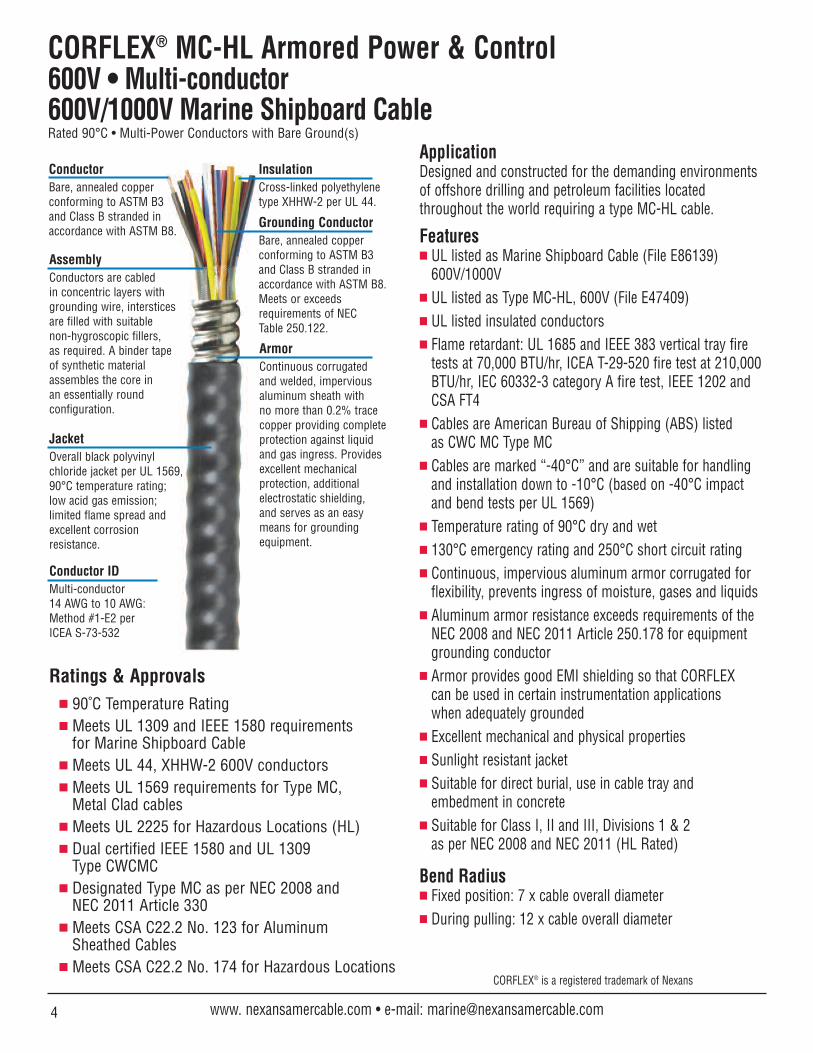
CORFLEX® MC-HL Armored Power & Control600V • Multi-conductor600V/1000V Marine Shipboard CableRated 90°C • Multi-Power Conductors with Bare Ground(s)
Ratings & Approvals 90˚C Temperature Rating Meets UL 1309 and IEEE 1580 requirements
for Marine Shipboard Cable Meets UL 44, XHHW-2 600V conductors Meets UL 1569 requirements for Type MC,
Metal Clad cables Meets UL 2225 for Hazardous Locations (HL) Dual certified IEEE 1580 and UL 1309
Type CWCMC Designated Type MC as per NEC 2008 and
NEC 2011 Article 330 Meets CSA C22.2 No. 123 for Aluminum
Sheathed Cables Meets CSA C22.2 No. 174 for Hazardous Locations
ApplicationDesigned and constructed for the demanding environments of offshore drilling and petroleum facilities located throughout the world requiring a type MC-HL cable.
Features UL listed as Marine Shipboard Cable (File E86139)
600V/1000V UL listed as Type MC-HL, 600V (File E47409) UL listed insulated conductors Flame retardant: UL 1685 and IEEE 383 vertical tray fire
tests at 70,000 BTU/hr, ICEA T-29-520 fire test at 210,000BTU/hr, IEC 60332-3 category A fire test, IEEE 1202 andCSA FT4
Cables are American Bureau of Shipping (ABS) listedas CWC MC Type MC
Cables are marked “-40°C” and are suitable for handlingand installation down to -10°C (based on -40°C impactand bend tests per UL 1569)
Temperature rating of 90°C dry and wet 130°C emergency rating and 250°C short circuit rating Continuous, impervious aluminum armor corrugated for
flexibility, prevents ingress of moisture, gases and liquids Aluminum armor resistance exceeds requirements of the
NEC 2008 and NEC 2011 Article 250.178 for equipmentgrounding conductor
Armor provides good EMI shielding so that CORFLEX can be used in certain instrumentation applications when adequately grounded
Excellent mechanical and physical properties Sunlight resistant jacket Suitable for direct burial, use in cable tray and
embedment in concrete Suitable for Class I, II and III, Divisions 1 & 2
as per NEC 2008 and NEC 2011 (HL Rated)
Bend Radius Fixed position: 7 x cable overall diameter During pulling: 12 x cable overall diameter
ConductorBare, annealed copperconforming to ASTM B3 and Class B stranded inaccordance with ASTM B8.
AssemblyConductors are cabledin concentric layers withgrounding wire, intersticesare filled with suitable non-hygroscopic fillers, as required. A binder tape of synthetic materialassembles the core in an essentially roundconfiguration.
InsulationCross-linked polyethylenetype XHHW-2 per UL 44.
Grounding ConductorBare, annealed copperconforming to ASTM B3 and Class B stranded inaccordance with ASTM B8.Meets or exceeds requirements of NECTable 250.122.
JacketOverall black polyvinylchloride jacket per UL 1569,90°C temperature rating; low acid gas emission;limited flame spread andexcellent corrosionresistance.
ArmorContinuous corrugated and welded, imperviousaluminum sheath withno more than 0.2% tracecopper providing completeprotection against liquidand gas ingress. Providesexcellent mechanicalprotection, additionalelectrostatic shielding,and serves as an easymeans for groundingequipment.
CORFLEX® is a registered trademark of Nexans
4 www. nexansamercable.com • e-mail: [email protected]
Conductor IDMulti-conductor 14 AWG to 10 AWG: Method #1-E2 perICEA S-73-532

5800-506-9473 • 713-896-5800 • Fax: 713-849-9009
Power & Control • 600V600V/1000V Marine Shipboard Cable
NexansDesignNo.
670155670142317677318345318352318360318378318386318394318402318410
670156670144317693318436318444318451318469318447318485318493318501
670157670146317719318527318535318543318550665148
23*4579
1215192537
23*4579
1215192537
23*4579
1237
(mils)3030303030303030303030
3030303030303030303030
3030303030303030
(inches)0.2730.3900.3360.3360.4170.4860.5610.6100.6690.7970.933
0.3450.3400.3850.4140.4780.5510.6390.6910.7600.8971.059
0.3610.4500.4490.4790.5560.6930.7451.227
(inches)0.4690.5550.5030.5320.6010.6450.7830.8110.9211.0051.218
0.5120.5550.5500.5990.6400.7770.8280.9360.9811.1901.374
0.5270.6200.6210.6410.7800.9370.9711.591
(mils)5050505050505050505050
5050505050505050505050
5050505050505060
Ω/kft2.55532.55532.55532.55532.55532.55532.55532.55532.55532.55532.5553
1.60821.60821.60821.60821.60821.60821.60821.60821.60821.60821.6082
1.01181.01181.01181.01181.01181.01181.01181.0118
InsulationThickness
NominalDiameterOver Core
NominalDiameter
Over ArmorJacket
Thickness(inches)
0.5810.6600.6060.6350.7040.7480.8870.9151.0281.1111.323
0.6140.6600.6530.7020.7440.8810.9321.0391.0851.2951.478
0.6320.7250.7240.7430.8841.0401.0741.725
NominalDiameter
Over Jacket
DCResistance
20°C Ω/kft
2.60642.60642.60642.60642.60642.60642.60642.60642.60642.60642.6064
1.64041.64041.64041.64041.64041.64041.64041.64041.64041.64041.6404
1.03201.03201.03201.03201.03201.03201.03201.0320
DCResistance
25°C 60 Hz Ω/kft
3.25833.25833.25833.25833.25833.25833.25833.25833.25833.25833.2583
2.05072.05072.05072.05072.05072.05072.05072.05072.05072.05072.0507
1.29021.29021.29021.29021.29021.29021.29021.2902
ACResistance
90°C Ω/kft@60Hz
0.03760.03760.03760.04970.05450.05960.06410.06660.06940.07430.0787
0.03530.03530.03530.04750.05260.05740.06200.06440.06720.07190.0765
0.03320.03320.03320.04540.05070.05790.06010.0744
InductiveReactance
90°C Amps/kft2.94892.94892.94892.95422.95662.95852.96042.96152.96272.96492.9668
1.86101.86101.86101.86631.86851.87061.87261.87371.87491.87691.8789
1.17561.17561.17561.18091.18321.18641.18741.1936
VoltageDropVolts/
75°C15151515141410101098
2020202018181313131110
3030282825251814
90°C1515151515151313131110
2020202020201515151412
3030303028282016
(lb/kft)155200191212263307388443572691986
1852262392803384375026357439871365
2313123193644846307321984
Approx.Net CableWeightNo. of
Cond. kcmil14(7w)14(7w)14(7w)14(7w)14(7w)14(7w)14(7w)14(7w)14(7w)14(7w)14(7w)
12(7w)12(7w)12(7w)12(7w)12(7w)12(7w)12(7w)12(7w)12(7w)12(7w)12(7w)
10(7w)10(7w)10(7w)10(7w)10(7w)10(7w)10(7w)10(7w)
ConductorSizeAWG/
AWG14(7w)
3x18(7w)14(7w)14(7w)14(7w)14(7w)14(7w)14(7w)14(7w)14(7w)14(7w)
12(7w)3x16(7w)12(7w)12(7w)12(7w)12(7w)12(7w)12(7w)12(7w)12(7w)12(7w)
10(7w)3x14(7)10(7w)10(7w)10(7w)10(7w)10(7w)10(7w)
GroundWireSize
Notes:1) Ampacities are in accordance with NEC 2008 Table 310.16 or NEC 2011 Table 310.15(B)(16) for conductors in raceway or direct
buried at 30°C ambient temperature and 90°C conductor temperature. The overcurrent protection shall not exceed 15 amperes for 14 AWG, 20 amperes for 12 AWG, and 30 amperes for 10 AWG copper conductors after any correction factors for ambienttemperature and number of conductors have been applied (NEC 2008 and NEC 2011 Article 240.4(D)). For correction factors fordifferent ambient temperatures and ampacities at different conductor temperatures, see NEC 2008 Table 310.16 or NEC 2011 Table 310.15(B)(16). Ampacities for cables having more than three conductors have been derated per NEC 2008 Article310.15(B)(2)(a) or NEC 2011 Article 310.15(B)(3)(a).
*Three conductor cables with 3 grounds are also suitable for VFD applications.
Ampacities(Note 1)
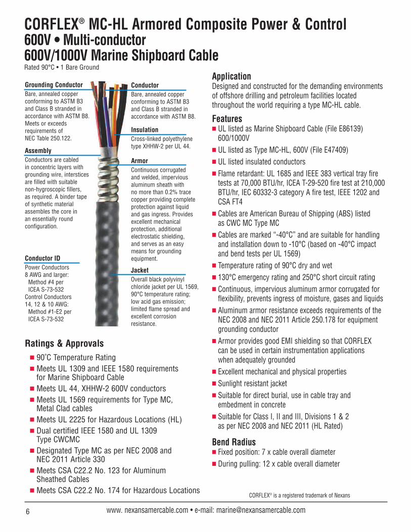
CORFLEX® MC-HL Armored Composite Power & Control600V • Multi-conductor600V/1000V Marine Shipboard CableRated 90°C • 1 Bare Ground
Ratings & Approvals 90˚C Temperature Rating Meets UL 1309 and IEEE 1580 requirements
for Marine Shipboard Cable Meets UL 44, XHHW-2 600V conductors Meets UL 1569 requirements for Type MC,
Metal Clad cables Meets UL 2225 for Hazardous Locations (HL) Dual certified IEEE 1580 and UL 1309
Type CWCMC Designated Type MC as per NEC 2008 and
NEC 2011 Article 330 Meets CSA C22.2 No. 123 for Aluminum
Sheathed Cables Meets CSA C22.2 No. 174 for Hazardous Locations
ApplicationDesigned and constructed for the demanding environments of offshore drilling and petroleum facilities located throughout the world requiring a type MC-HL cable.
Features UL listed as Marine Shipboard Cable (File E86139)
600/1000V UL listed as Type MC-HL, 600V (File E47409) UL listed insulated conductors Flame retardant: UL 1685 and IEEE 383 vertical tray fire
tests at 70,000 BTU/hr, ICEA T-29-520 fire test at 210,000BTU/hr, IEC 60332-3 category A fire test, IEEE 1202 andCSA FT4
Cables are American Bureau of Shipping (ABS) listedas CWC MC Type MC
Cables are marked “-40°C” and are suitable for handlingand installation down to -10°C (based on -40°C impactand bend tests per UL 1569)
Temperature rating of 90°C dry and wet 130°C emergency rating and 250°C short circuit rating Continuous, impervious aluminum armor corrugated for
flexibility, prevents ingress of moisture, gases and liquids Aluminum armor resistance exceeds requirements of the
NEC 2008 and NEC 2011 Article 250.178 for equipmentgrounding conductor
Armor provides good EMI shielding so that CORFLEXcan be used in certain instrumentation applicationswhen adequately grounded
Excellent mechanical and physical properties Sunlight resistant jacket Suitable for direct burial, use in cable tray and
embedment in concrete Suitable for Class I, II and III, Divisions 1 & 2
as per NEC 2008 and NEC 2011 (HL Rated)
Bend Radius Fixed position: 7 x cable overall diameter During pulling: 12 x cable overall diameter
ConductorBare, annealed copperconforming to ASTM B3 and Class B stranded inaccordance with ASTM B8.
AssemblyConductors are cabledin concentric layers withgrounding wire, intersticesare filled with suitable non-hygroscopic fillers, as required. A binder tape of synthetic materialassembles the core in an essentially roundconfiguration.
InsulationCross-linked polyethylenetype XHHW-2 per UL 44.
Grounding ConductorBare, annealed copperconforming to ASTM B3 and Class B stranded inaccordance with ASTM B8.Meets or exceedsrequirements ofNEC Table 250.122.
JacketOverall black polyvinylchloride jacket per UL 1569,90°C temperature rating; low acid gas emission;limited flame spread andexcellent corrosionresistance.
ArmorContinuous corrugated and welded, imperviousaluminum sheath withno more than 0.2% tracecopper providing completeprotection against liquidand gas ingress. Providesexcellent mechanicalprotection, additionalelectrostatic shielding,and serves as an easymeans for groundingequipment.
CORFLEX® is a registered trademark of Nexans
6 www. nexansamercable.com • e-mail: [email protected]
Conductor IDPower Conductors8 AWG and larger:
Method #4 per ICEA S-73-532
Control Conductors14, 12 & 10 AWG:
Method #1-E2 per ICEA S-73-532
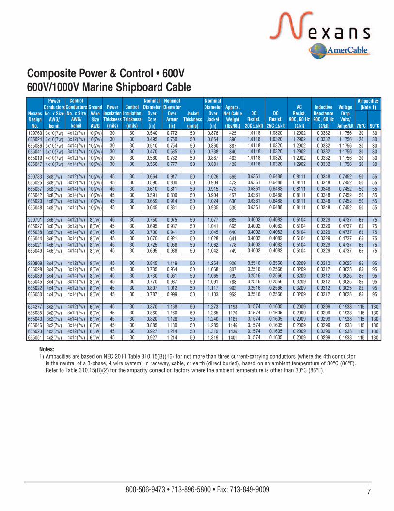
Notes:1) Ampacities are based on NEC 2011 Table 310.15(B)(16) for not more than three current-carrying conductors (where the 4th conductor
is the neutral of a 3-phase, 4 wire system) in raceway, cable, or earth (direct buried), based on an ambient temperature of 30°C (86°F).Refer to Table 310.15(B)(2) for the ampacity correction factors where the ambient temperature is other than 30°C (86°F).
7800-506-9473 • 713-896-5800 • Fax: 713-849-9009
JacketThickness
(mils)505050505050
505050505050
505050505050
505050505050
505050505050
75°C303030303030
505050505050
656565656565
858585858585
115115115115115115
90°C303030303030
555555555555
757575757575
959595959595
130130130130130130
ControlConductorsNo. x Size
AWG/kcmil
4x12(7w)3x12(7w)4x14(7w)3x14(7w)4x12(7w)4x14(7w)
4x12(7w)3x12(7w)4x14(7w)3x14(7w)4x12(7w)4x14(7w)
4x12(7w)3x12(7w)4x14(7w)3x14(7w)4x12(7w)4x14(7w)
4x12(7w)3x12(7w)4x14(7w)3x14(7w)4x12(7w)4x14(7w)
4x12(7w)3x12(7w)4x14(7w)3x14(7w)4x12(7w)4x14(7w)
NexansDesignNo.
199760665024665036665041665019665047
290783665025665037665042665020665048
290791665027665038665044665021665049
290809665028665039665045665022665050
654277665035665040665046665023665051
PowerConductorsNo. x Size
AWG/kcmil
3x10(7w)3x10(7w)3x10(7w)3x10(7w)4x10(7w)4x10(7w)
3x8(7w)3x8(7w)3x8(7w)3x8(7w)4x8(7w)4x8(7w)
3x6(7w)3x6(7w)3x6(7w)3x6(7w)4x6(7w)4x6(7w)
3x4(7w)3x4(7w)3x4(7w)3x4(7w)4x4(7w)4x4(7w)
3x2(7w)3x2(7w)3x2(7w)3x2(7w)4x2(7w)4x2(7w)
ControlInsulationThickness(mils)
303030303030
303030303030
303030303030
303030303030
303030303030
PowerInsulationThickness(mils)
303030303030
454545454545
454545454545
454545454545
454545454545
NominalDiameter
OverArmor(in)
0.7720.7500.7540.6350.7820.777
0.9170.8000.8110.8000.9140.831
0.9750.9370.9410.9210.9580.938
1.1490.9640.9610.9871.0120.999
1.1681.1601.1281.1801.2141.214
NominalDiameter
OverCore(in)
0.5400.4950.5100.4700.5600.550
0.6640.5900.6100.5910.6590.645
0.7500.6950.7000.6700.7250.695
0.8450.7350.7300.7700.8070.787
0.8700.8600.8200.8850.9270.927
NominalDiameter
OverJacket(in)
0.8760.8540.8600.7380.8870.881
1.0260.9040.9150.9041.0240.935
1.0771.0411.0451.0281.0621.042
1.2541.0681.0651.0911.1171.103
1.2731.2651.2401.2851.3191.319
Ampacities(Note 1)
DCResist.
20C Ω/kft1.01181.01181.01181.01181.01181.0118
0.63610.63610.63610.63610.63610.6361
0.40020.40020.40020.40020.40020.4002
0.25160.25160.25160.25160.25160.2516
0.15740.15740.15740.15740.15740.1574
DCResist.
25C Ω/kft1.03201.03201.03201.03201.03201.0320
0.64880.64880.64880.64880.64880.6488
0.40820.40820.40820.40820.40820.4082
0.25660.25660.25660.25660.25660.2566
0.16050.16050.16050.16050.16050.1605
ACResist.
90C, 60 HzΩ/kft
1.29021.29021.29021.29021.29021.2902
0.81110.81110.81110.81110.81110.8111
0.51040.51040.51040.51040.51040.5104
0.32090.32090.32090.32090.32090.3209
0.20090.20090.20090.20090.20090.2009
InductiveReactance90C, 60 HzΩ/kft
0.03320.03320.03320.03320.03320.0332
0.03480.03480.03480.03480.03480.0348
0.03290.03290.03290.03290.03290.0329
0.03120.03120.03120.03120.03120.0312
0.02990.02990.02990.02990.02990.0299
VoltageDropVolts/
Amps/kft1.17561.17561.17561.17561.17561.1756
0.74520.74520.74520.74520.74520.7452
0.47370.47370.47370.47370.47370.4737
0.30250.30250.30250.30250.30250.3025
0.19380.19380.19380.19380.19380.1938
GroundWire SizeAWG
10(7w)10(7w)10(7w)10(7w)10(7w)10(7w)
10(7w)10(7w)10(7w)10(7w)10(7w)10(7w)
8(7w)8(7w)8(7w)8(7w)8(7w)8(7w)
8(7w)8(7w)8(7w)8(7w)8(7w)8(7w)
6(7w)6(7w)6(7w)6(7w)6(7w)6(7w)
Approx.Net CableWeight(lbs/Kft)
425396387340463428
565473478457630535
685665640641778749
926807799788993953
119811701165114614361401
Composite Power & Control • 600V600V/1000V Marine Shipboard Cable
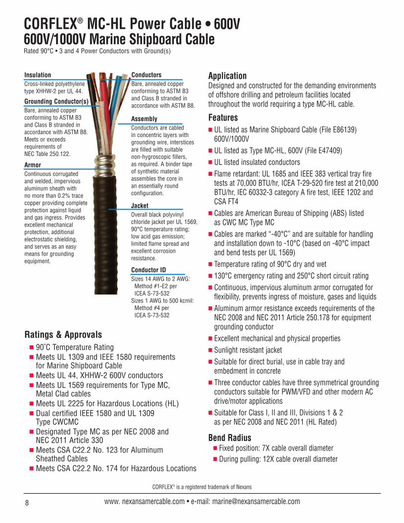
CORFLEX® MC-HL Power Cable • 600V600V/1000V Marine Shipboard CableRated 90°C • 3 and 4 Power Conductors with Ground(s)
Ratings & Approvals 90˚C Temperature Rating Meets UL 1309 and IEEE 1580 requirements
for Marine Shipboard Cable Meets UL 44, XHHW-2 600V conductors Meets UL 1569 requirements for Type MC,
Metal Clad cables Meets UL 2225 for Hazardous Locations (HL) Dual certified IEEE 1580 and UL 1309
Type CWCMC Designated Type MC as per NEC 2008 and
NEC 2011 Article 330 Meets CSA C22.2 No. 123 for Aluminum
Sheathed Cables Meets CSA C22.2 No. 174 for Hazardous Locations
ApplicationDesigned and constructed for the demanding environments of offshore drilling and petroleum facilities located throughout the world requiring a type MC-HL cable.
Features UL listed as Marine Shipboard Cable (File E86139)
600V/1000V UL listed as Type MC-HL, 600V (File E47409) UL listed insulated conductors Flame retardant: UL 1685 and IEEE 383 vertical tray fire
tests at 70,000 BTU/hr, ICEA T-29-520 fire test at 210,000BTU/hr, IEC 60332-3 category A fire test, IEEE 1202 andCSA FT4
Cables are American Bureau of Shipping (ABS) listedas CWC MC Type MC
Cables are marked “-40°C” and are suitable for handlingand installation down to -10°C (based on -40°C impactand bend tests per UL 1569)
Temperature rating of 90°C dry and wet 130°C emergency rating and 250°C short circuit rating Continuous, impervious aluminum armor corrugated for
flexibility, prevents ingress of moisture, gases and liquids Aluminum armor resistance exceeds requirements of the
NEC 2008 and NEC 2011 Article 250.178 for equipmentgrounding conductor
Excellent mechanical and physical properties Sunlight resistant jacket Suitable for direct burial, use in cable tray and
embedment in concrete Three conductor cables have three symmetrical grounding
conductors suitable for PWM/VFD and other modern ACdrive/motor applications
Suitable for Class I, II and III, Divisions 1 & 2 as per NEC 2008 and NEC 2011 (HL Rated)
Bend Radius Fixed position: 7X cable overall diameter During pulling: 12X cable overall diameter
ConductorsBare, annealed copperconforming to ASTM B3 and Class B stranded inaccordance with ASTM B8.
AssemblyConductors are cabledin concentric layers withgrounding wire, intersticesare filled with suitable non-hygroscopic fillers, as required. A binder tape of synthetic materialassembles the core in an essentially roundconfiguration.
InsulationCross-linked polyethylenetype XHHW-2 per UL 44.
Grounding Conductor(s)Bare, annealed copperconforming to ASTM B3 and Class B stranded inaccordance with ASTM B8.Meets or exceedsrequirements ofNEC Table 250.122.
JacketOverall black polyvinylchloride jacket per UL 1569,90°C temperature rating; low acid gas emission; limited flame spread and excellent corrosion resistance.
ArmorContinuous corrugated and welded, imperviousaluminum sheath withno more than 0.2% tracecopper providing completeprotection against liquidand gas ingress. Providesexcellent mechanicalprotection, additionalelectrostatic shielding,and serves as an easymeans for groundingequipment.
CORFLEX® is a registered trademark of Nexans
8 www. nexansamercable.com • e-mail: [email protected]
Conductor IDSizes 14 AWG to 2 AWG:
Method #1-E2 perICEA S-73-532
Sizes 1 AWG to 500 kcmil: Method #4 perICEA S-73-532
9800-506-9473 • 713-896-5800 • Fax: 713-849-9009
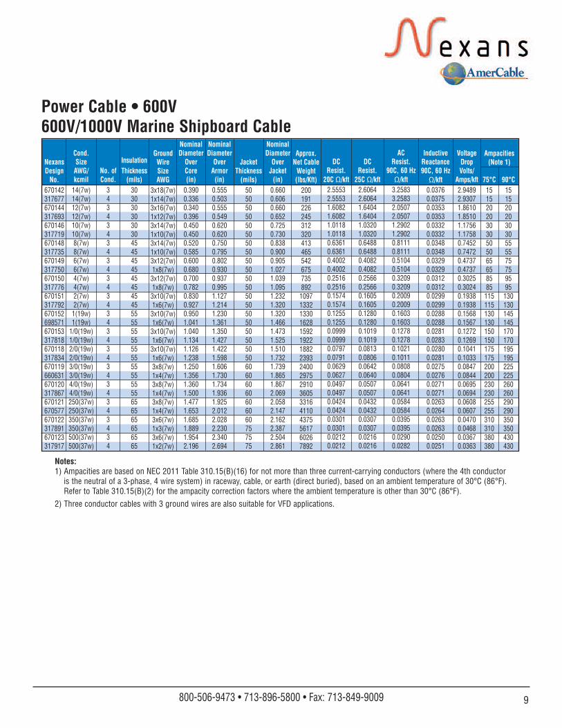
NexansDesignNo.
670142317677670144317693670146317719670148317735670149317750670150317776670151317792670152698571670153317818670118317834670119660631670120317867670121670577670122317891670123317917
JacketThickness
(mils)505050505050505050505050505050505050505060606060606060757575
75°C151520203030505065658585115115130130150150175175200200230230255255310310380380
90°C151520203030555575759595130130145145170170195195225225260260290290350350430430
Cond.SizeAWG/kcmil
14(7w)14(7w)12(7w)12(7w)10(7w)10(7w)8(7w)8(7w)6(7w)6(7w)4(7w)4(7w)2(7w)2(7w)
1(19w)1(19w)
1/0(19w)1/0(19w)2/0(19w)2/0(19w)3/0(19w)3/0(19w)4/0(19w)4/0(19w)250(37w)250(37w)350(37w)350(37w)500(37w)500(37w)
No. ofCond.
343434343434343434343434343434
InsulationThickness(mils)
303030303030454545454545454555555555555555555555656565656565
NominalDiameter
OverArmor(in)
0.5550.5030.5550.5490.6200.6200.7500.7950.8020.9300.9370.9951.1271.2141.2301.3611.3501.4271.4221.5981.6061.7301.7341.9361.9252.0122.0282.2302.3402.694
NominalDiameter
OverCore(in)
0.3900.3360.3400.3960.4500.4500.5200.5850.6000.6800.7000.7820.8300.9270.9501.0411.0401.1341.1261.2381.2501.3561.3601.5001.4771.6531.6851.8891.9542.196
NominalDiameter
OverJacket(in)
0.6600.6060.6600.6520.7250.7300.8380.9000.9051.0271.0391.0951.2321.3201.3201.4661.4731.5251.5101.7321.7391.8651.8672.0692.0582.1472.1622.3872.5042.861
Ampacities(Note 1)DC
Resist.20C Ω/kft
2.55532.55531.60821.60821.01181.01180.63610.63610.40020.40020.25160.25160.15740.15740.12550.12550.09990.09990.07970.07910.06290.06270.04970.04970.04240.04240.03010.03010.02120.0212
DCResist.
25C Ω/kft2.60642.60641.64041.64041.03201.03200.64880.64880.40820.40820.25660.25660.16050.16050.12800.12800.10190.10190.08130.08060.06420.06400.05070.05070.04320.04320.03070.03070.02160.0216
ACResist.
90C, 60 HzΩ/kft
3.25833.25832.05072.05071.29021.29020.81110.81110.51040.51040.32090.32090.20090.20090.16030.16030.12780.12780.10210.10110.08080.08040.06410.06410.05840.05840.03950.03950.02900.0282
InductiveReactance90C, 60 HzΩ/kft
0.03760.03750.03530.03530.03320.03320.03480.03480.03290.03290.03120.03120.02990.02990.02880.02880.02810.02830.02800.02810.02750.02760.02710.02710.02630.02640.02630.02630.02500.0251
VoltageDropVolts/
Amps/kft2.94892.93071.86101.85101.17561.17580.74520.74720.47370.47370.30250.30240.19380.19380.15680.15670.12720.12690.10410.10330.08470.08440.06950.06940.06080.06070.04700.04680.03670.0363
GroundWire SizeAWG
3x18(7w)1x14(7w)3x16(7w)1x12(7w)3x14(7w)1x10(7w)3x14(7w)1x10(7w)3x12(7w)1x8(7w)
3x12(7w)1x8(7w)
3x10(7w)1x6(7w)
3x10(7w)1x6(7w)
3x10(7w)1x6(7w)
3x10(7w)1x6(7w)3x8(7w)1x4(7w)3x8(7w)1x4(7w)3x8(7w)1x4(7w)3x6(7w)1x3(7w)3x6(7w)1x2(7w)
Approx.Net CableWeight(lbs/Kft)
200191226245312320413465542675735892
109713321330162815921922188223932400297529103605331641104375561760267892
Power Cable • 600V600V/1000V Marine Shipboard Cable
Notes:1) Ampacities are based on NEC 2011 Table 310.15(B)(16) for not more than three current-carrying conductors (where the 4th conductor
is the neutral of a 3-phase, 4 wire system) in raceway, cable, or earth (direct buried), based on an ambient temperature of 30°C (86°F).Refer to Table 310.15(B)(2) for the ampacity correction factors where the ambient temperature is other than 30°C (86°F).
2) Three conductor cables with 3 ground wires are also suitable for VFD applications.
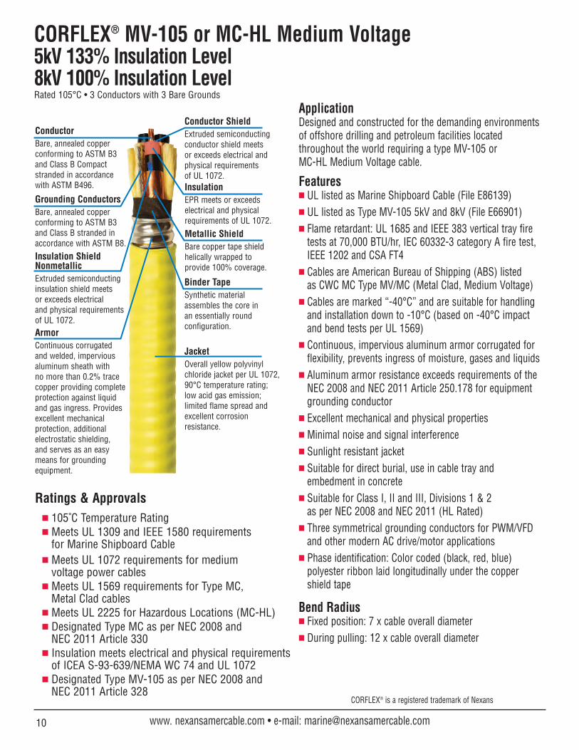
CORFLEX® MV-105 or MC-HL Medium Voltage5kV 133% Insulation Level8kV 100% Insulation LevelRated 105°C • 3 Conductors with 3 Bare Grounds
ApplicationDesigned and constructed for the demanding environments of offshore drilling and petroleum facilities located throughout the world requiring a type MV-105 orMC-HL Medium Voltage cable.
Features UL listed as Marine Shipboard Cable (File E86139) UL listed as Type MV-105 5kV and 8kV (File E66901) Flame retardant: UL 1685 and IEEE 383 vertical tray fire
tests at 70,000 BTU/hr, IEC 60332-3 category A fire test,IEEE 1202 and CSA FT4
Cables are American Bureau of Shipping (ABS) listedas CWC MC Type MV/MC (Metal Clad, Medium Voltage)
Cables are marked “-40°C” and are suitable for handlingand installation down to -10°C (based on -40°C impactand bend tests per UL 1569)
Continuous, impervious aluminum armor corrugated forflexibility, prevents ingress of moisture, gases and liquids
Aluminum armor resistance exceeds requirements of the NEC 2008 and NEC 2011 Article 250.178 for equipmentgrounding conductor
Excellent mechanical and physical properties Minimal noise and signal interference Sunlight resistant jacket Suitable for direct burial, use in cable tray and
embedment in concrete Suitable for Class I, II and III, Divisions 1 & 2
as per NEC 2008 and NEC 2011 (HL Rated) Three symmetrical grounding conductors for PWM/VFD
and other modern AC drive/motor applications Phase identification: Color coded (black, red, blue)
polyester ribbon laid longitudinally under the coppershield tape
Bend Radius Fixed position: 7 x cable overall diameter During pulling: 12 x cable overall diameter
InsulationEPR meets or exceedselectrical and physicalrequirements of UL 1072.
Conductor ShieldExtruded semiconductingconductor shield meetsor exceeds electrical andphysical requirementsof UL 1072.
Insulation ShieldNonmetallicExtruded semiconductinginsulation shield meetsor exceeds electricaland physical requirementsof UL 1072.
Metallic ShieldBare copper tape shieldhelically wrapped toprovide 100% coverage.
ConductorBare, annealed copperconforming to ASTM B3 and Class B Compactstranded in accordance with ASTM B496.
JacketOverall yellow polyvinylchloride jacket per UL 1072,90°C temperature rating; low acid gas emission;limited flame spread andexcellent corrosionresistance.
ArmorContinuous corrugated and welded, imperviousaluminum sheath withno more than 0.2% tracecopper providing completeprotection against liquidand gas ingress. Providesexcellent mechanicalprotection, additionalelectrostatic shielding,and serves as an easymeans for groundingequipment.
Binder TapeSynthetic materialassembles the core inan essentially roundconfiguration.
CORFLEX® is a registered trademark of Nexans
10 www. nexansamercable.com • e-mail: [email protected]
Ratings & Approvals 105˚C Temperature Rating Meets UL 1309 and IEEE 1580 requirements
for Marine Shipboard Cable Meets UL 1072 requirements for medium
voltage power cables Meets UL 1569 requirements for Type MC,
Metal Clad cables Meets UL 2225 for Hazardous Locations (MC-HL) Designated Type MC as per NEC 2008 and
NEC 2011 Article 330 Insulation meets electrical and physical requirements
of ICEA S-93-639/NEMA WC 74 and UL 1072 Designated Type MV-105 as per NEC 2008 and
NEC 2011 Article 328
Grounding ConductorsBare, annealed copperconforming to ASTM B3and Class B stranded inaccordance with ASTM B8.
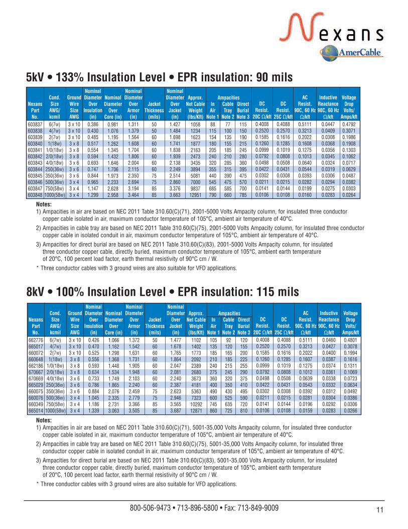
5kV • 133% Insulation Level • EPR insulation: 90 mils
NexansPartNo.
662776665017660072660648662186670667670669665029660075660076660349665014
JacketThickness
(mils)506060606060606075758585
Cond.SizeAWG/kcmil6(7w)4(7w)2(7w)1(18w)
1/0(18w)2/0(18w)4/0(18w)250(36w)350(36w)500(36w)750(58w)
1000(58w)
GroundWireSizeAWG
3 x 103 x 103 x 103 x 83 x 83 x 83 x 63 x 63 x 63 x 43 x 43 x 4
NominalDiameter
OverInsulation
(in)0.4260.4700.5250.5560.5930.6340.7330.7860.8841.0451.1861.339
NominalDiameter
OverArmor(in)
1.3721.5421.6311.7311.9051.9482.1032.2402.4592.7793.3663.505
NominalDiameter
OverJacket(in)
1.4771.6781.7651.8642.0472.0812.2402.3872.6232.9463.5653.687
InAir
Note 1105135185210240275360400490600745860
CableTray
Note 292
120165185215245320350430525635725
DirectBurialNote 3
120155200225255290375410495590720810
DCResist.
20C Ω/kft0.40080.25200.15850.12600.09990.07920.04980.04220.03020.02110.01410.0106
DCResist.
25C Ω/kft0.40880.25700.16160.12850.10190.08080.05080.04310.03080.02150.01440.0108
ACResist.
90C, 60 HzΩ/kft
0.51110.32130.20220.16070.12750.10120.06390.05430.03920.02810.01960.0159
InductiveReactance90C, 60 HzΩ/kft
0.04600.04270.04000.03870.03740.03610.03380.03320.03120.03040.02920.0283
VoltageDropVolts/
Amps/kft0.48010.30780.19940.16160.13110.10690.07230.06340.04920.03860.03060.0266
AmpacitiesNominalDiameter
OverCore (in)
1.0661.1621.2981.3681.4481.5341.7491.8652.0762.3352.7313.063
Approx.Net CableWeight(lbs/Kft)
1102140217732092238926803673418153637323
1029212871
8kV • 100% Insulation Level • EPR insulation: 115 mils
Notes:1) Ampacities in air are based on NEC 2011 Table 310.60(C)(71), 5001-35,000 Volts Ampacity column, for insulated three conductor
copper cable isolated in air, maximum conductor temperature of 105°C, ambient air temperature of 40°C.
2) Ampacities in cable tray are based on NEC 2011 Table 310.60(C)(75), 5001-35,000 Volts Ampacity column, for insulated threeconductor copper cable in isolated conduit in air, maximum conductor temperature of 105°C, ambient air temperature of 40°C.
3) Ampacities for direct burial are based on NEC 2011 Table 310.60(C)(83), 5001-35,000 Volts Ampacity column, for insulatedthree conductor copper cable, directly buried, maximum conductor temperature of 105°C, ambient earth temperatureof 20°C, 100 percent load factor, earth thermal resistivity of 90°C cm / W.
* Three conductor cables with 3 ground wires are also suitable for VFD applications.
Notes:1) Ampacities in air are based on NEC 2011 Table 310.60(C)(71), 2001-5000 Volts Ampacity column, for insulated three conductor
copper cable isolated in air, maximum conductor temperature of 105°C, ambient air temperature of 40°C.
2) Ampacities in cable tray are based on NEC 2011 Table 310.60(C)(75), 2001-5000 Volts Ampacity column, for insulated three conductorcopper cable in isolated conduit in air, maximum conductor temperature of 105°C, ambient air temperature of 40°C.
3) Ampacities for direct burial are based on NEC 2011 Table 310.60(C)(83), 2001-5000 Volts Ampacity column, for insulated three conductor copper cable, directly buried, maximum conductor temperature of 105°C, ambient earth temperatureof 20°C, 100 percent load factor, earth thermal resistivity of 90°C cm / W.
* Three conductor cables with 3 ground wires are also suitable for VFD applications.
11800-506-9473 • 713-896-5800 • Fax: 713-849-9009
NexansPartNo.
603837603838603839603840603841603842603843603844603845603846603847603848
JacketThickness
(mils)505060606060606075758585
Cond.SizeAWG/kcmil6(7w)4(7w)2(7w)
1(18w)1/0(18w)2/0(18w)4/0(18w)250(36w)350(36w)500(36w)750(58w)1000(58w)
GroundWireSizeAWG
3 x 103 x 103 x 103 x 83 x 83 x 83 x 63 x 63 x 63 x 43 x 43 x 4
NominalDiameter
OverInsulation
(in)0.3860.4300.4850.5170.5540.5940.6930.7470.8440.9651.1471.299
NominalDiameter
OverArmor(in)
1.3111.3791.5641.6081.7041.8062.0042.1152.3502.6943.1943.464
NominalDiameter
OverJacket(in)
1.4271.4841.6981.7411.8381.9392.1382.2492.5142.8603.3763.663
InAir
Note 188115154180205240320355440545685790
CableTray
Note 277
100135155185210285315390475585660
DirectBurialNote 3
115150190215245280360395475570700785
DCResist.
20C Ω/kft0.40080.25200.15850.12600.09990.07920.04980.04220.03020.02110.01410.0106
DCResist.
25C Ω/kft0.40880.25700.16160.12850.10190.08080.05080.04310.03080.02150.01440.0108
ACResist.
90C, 60 HzΩ/kft
0.51110.32130.20220.16080.12750.10130.06400.05440.03930.02820.01990.0160
InductiveReactance90C, 60 HzΩ/kft
0.04470.04090.03080.03680.03560.03450.03240.03190.03060.02940.02750.0283
VoltageDropVolts/
Amps/kft0.47920.30710.19860.19080.13030.10620.07170.06290.04870.03820.03030.0264
AmpacitiesNominalDiameter
OverCore (in)
0.9811.0761.1951.2621.3451.4321.6461.7061.9732.2332.6282.958
Approx.Net CableWeight(lbs/Kft)
10581234162318772163247334353894508170009837
12951
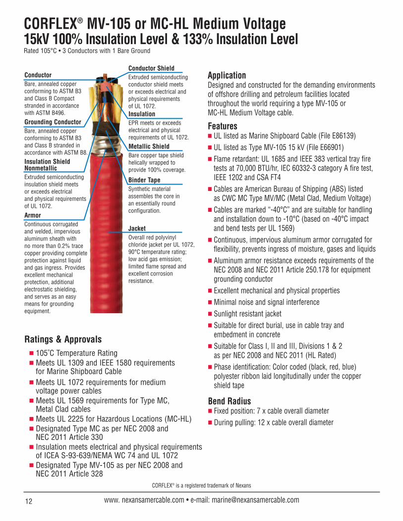
CORFLEX® MV-105 or MC-HL Medium Voltage15kV 100% Insulation Level & 133% Insulation LevelRated 105°C • 3 Conductors with 1 Bare Ground
Ratings & Approvals 105˚C Temperature Rating Meets UL 1309 and IEEE 1580 requirements
for Marine Shipboard Cable Meets UL 1072 requirements for medium
voltage power cables Meets UL 1569 requirements for Type MC,
Metal Clad cables Meets UL 2225 for Hazardous Locations (MC-HL) Designated Type MC as per NEC 2008 and
NEC 2011 Article 330 Insulation meets electrical and physical requirements
of ICEA S-93-639/NEMA WC 74 and UL 1072 Designated Type MV-105 as per NEC 2008 and
NEC 2011 Article 328
ApplicationDesigned and constructed for the demanding environments of offshore drilling and petroleum facilities located throughout the world requiring a type MV-105 or MC-HL Medium Voltage cable.
Features UL listed as Marine Shipboard Cable (File E86139) UL listed as Type MV-105 15 kV (File E66901) Flame retardant: UL 1685 and IEEE 383 vertical tray fire
tests at 70,000 BTU/hr, IEC 60332-3 category A fire test,IEEE 1202 and CSA FT4
Cables are American Bureau of Shipping (ABS) listedas CWC MC Type MV/MC (Metal Clad, Medium Voltage)
Cables are marked “-40°C” and are suitable for handlingand installation down to -10°C (based on -40°C impactand bend tests per UL 1569)
Continuous, impervious aluminum armor corrugated forflexibility, prevents ingress of moisture, gases and liquids
Aluminum armor resistance exceeds requirements of the NEC 2008 and NEC 2011 Article 250.178 for equipmentgrounding conductor
Excellent mechanical and physical properties Minimal noise and signal interference Sunlight resistant jacket Suitable for direct burial, use in cable tray and
embedment in concrete Suitable for Class I, II and III, Divisions 1 & 2
as per NEC 2008 and NEC 2011 (HL Rated) Phase identification: Color coded (black, red, blue)
polyester ribbon laid longitudinally under the coppershield tape
Bend Radius Fixed position: 7 x cable overall diameter During pulling: 12 x cable overall diameter
CORFLEX® is a registered trademark of Nexans
12 www. nexansamercable.com • e-mail: [email protected]
JacketOverall red polyvinylchloride jacket per UL 1072,90°C temperature rating; low acid gas emission;limited flame spread andexcellent corrosionresistance.
InsulationEPR meets or exceedselectrical and physicalrequirements of UL 1072.
Conductor ShieldExtruded semiconductingconductor shield meetsor exceeds electrical andphysical requirementsof UL 1072.
Metallic ShieldBare copper tape shieldhelically wrapped toprovide 100% coverage.
Binder TapeSynthetic materialassembles the core inan essentially roundconfiguration.
Insulation ShieldNonmetallicExtruded semiconductinginsulation shield meetsor exceeds electricaland physical requirementsof UL 1072.
ConductorBare, annealed copperconforming to ASTM B3 and Class B Compactstranded in accordance with ASTM B496.
ArmorContinuous corrugated and welded, imperviousaluminum sheath withno more than 0.2% tracecopper providing completeprotection against liquidand gas ingress. Providesexcellent mechanicalprotection, additionalelectrostatic shielding,and serves as an easymeans for groundingequipment.
Grounding ConductorBare, annealed copperconforming to ASTM B3 and Class B stranded inaccordance with ASTM B8.
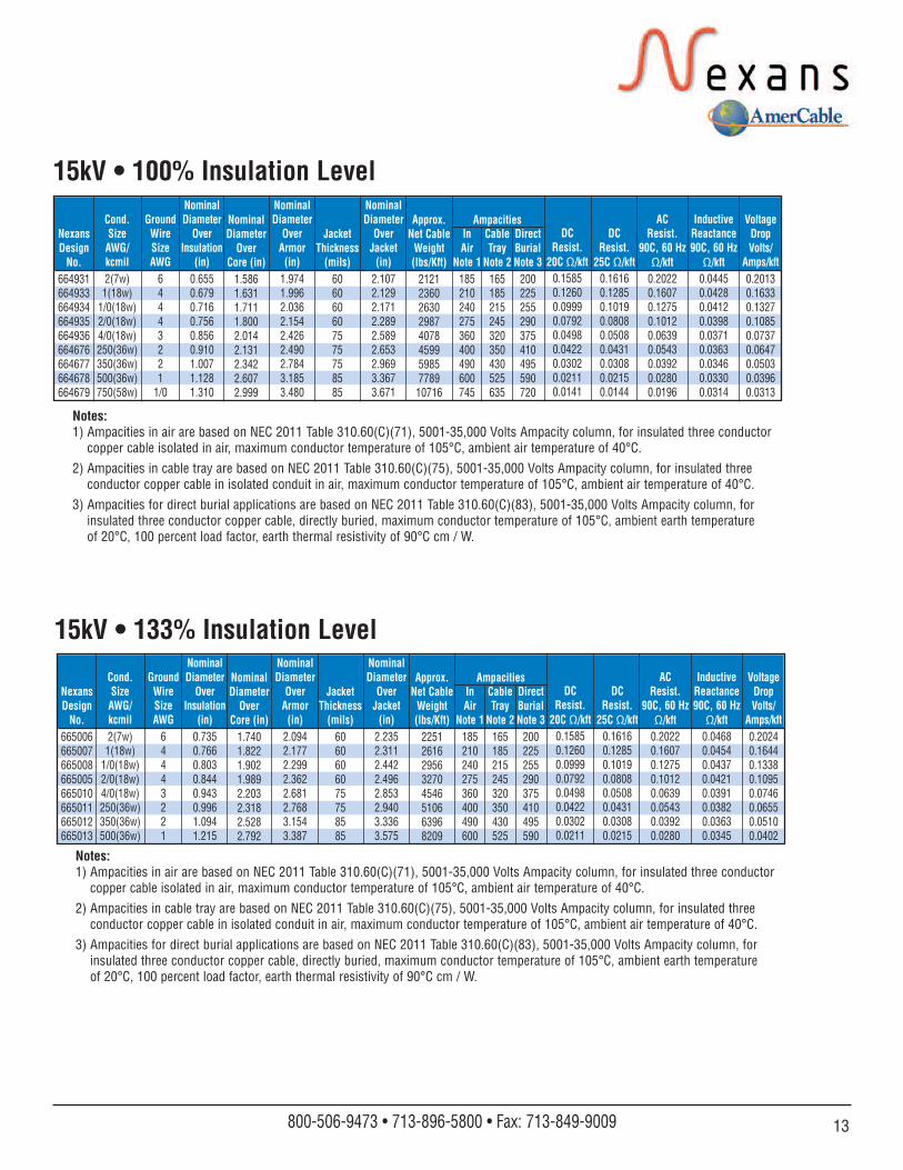
15kV • 100% Insulation Level
15kV • 133% Insulation Level
NexansDesignNo.
664931664933664934664935664936664676664677664678664679
JacketThickness
(mils)606060607575758585
InAir
Note 1185210240275360400490600745
CableTray
Note 2165185215245320350430525635
DirectBurialNote 3
200225255290375410495590720
Cond.SizeAWG/kcmil2(7w)1(18w)
1/0(18w)2/0(18w)4/0(18w)250(36w)350(36w)500(36w)750(58w)
GroundWireSizeAWG
64443221
1/0
NominalDiameter
OverInsulation
(in)0.6550.6790.7160.7560.8560.9101.0071.1281.310
NominalDiameter
OverArmor(in)
1.9741.9962.0362.1542.4262.4902.7843.1853.480
NominalDiameter
OverJacket(in)
2.1072.1292.1712.2892.5892.6532.9693.3673.671
AmpacitiesDC
Resist.20C Ω/kft
0.15850.12600.09990.07920.04980.04220.03020.02110.0141
DCResist.
25C Ω/kft0.16160.12850.10190.08080.05080.04310.03080.02150.0144
ACResist.
90C, 60 HzΩ/kft
0.20220.16070.12750.10120.06390.05430.03920.02800.0196
InductiveReactance90C, 60 HzΩ/kft
0.04450.04280.04120.03980.03710.03630.03460.03300.0314
VoltageDropVolts/
Amps/kft0.20130.16330.13270.10850.07370.06470.05030.03960.0313
NominalDiameter
OverCore (in)
1.5861.6311.7111.8002.0142.1312.3422.6072.999
Approx.Net CableWeight(lbs/Kft)
2121236026302987407845995985778910716
Notes:1) Ampacities in air are based on NEC 2011 Table 310.60(C)(71), 5001-35,000 Volts Ampacity column, for insulated three conductor
copper cable isolated in air, maximum conductor temperature of 105°C, ambient air temperature of 40°C.
2) Ampacities in cable tray are based on NEC 2011 Table 310.60(C)(75), 5001-35,000 Volts Ampacity column, for insulated threeconductor copper cable in isolated conduit in air, maximum conductor temperature of 105°C, ambient air temperature of 40°C.
3) Ampacities for direct burial applications are based on NEC 2011 Table 310.60(C)(83), 5001-35,000 Volts Ampacity column, forinsulated three conductor copper cable, directly buried, maximum conductor temperature of 105°C, ambient earth temperature of 20°C, 100 percent load factor, earth thermal resistivity of 90°C cm / W.
NexansDesignNo.
665006665007665008665005665010665011665012665013
JacketThickness
(mils)6060606075758585
InAir
Note 1185210240275360400490600
CableTray
Note 2165185215245320350430525
DirectBurialNote 3
200225255290375410495590
Cond.SizeAWG/kcmil2(7w)
1(18w)1/0(18w)2/0(18w)4/0(18w)250(36w)350(36w)500(36w)
GroundWireSizeAWG
64443221
NominalDiameter
OverInsulation
(in)0.7350.7660.8030.8440.9430.9961.0941.215
NominalDiameter
OverArmor(in)
2.0942.1772.2992.3622.6812.7683.1543.387
NominalDiameter
OverJacket(in)
2.2352.3112.4422.4962.8532.9403.3363.575
AmpacitiesDC
Resist.20C Ω/kft
0.15850.12600.09990.07920.04980.04220.03020.0211
DCResist.
25C Ω/kft0.16160.12850.10190.08080.05080.04310.03080.0215
ACResist.
90C, 60 HzΩ/kft
0.20220.16070.12750.10120.06390.05430.03920.0280
InductiveReactance90C, 60 HzΩ/kft
0.04680.04540.04370.04210.03910.03820.03630.0345
VoltageDropVolts/
Amps/kft0.20240.16440.13380.10950.07460.06550.05100.0402
NominalDiameter
OverCore (in)
1.7401.8221.9021.9892.2032.3182.5282.792
Approx.Net CableWeight(lbs/Kft)
22512616295632704546510663968209
Notes:1) Ampacities in air are based on NEC 2011 Table 310.60(C)(71), 5001-35,000 Volts Ampacity column, for insulated three conductor
copper cable isolated in air, maximum conductor temperature of 105°C, ambient air temperature of 40°C.
2) Ampacities in cable tray are based on NEC 2011 Table 310.60(C)(75), 5001-35,000 Volts Ampacity column, for insulated threeconductor copper cable in isolated conduit in air, maximum conductor temperature of 105°C, ambient air temperature of 40°C.
3) Ampacities for direct burial applications are based on NEC 2011 Table 310.60(C)(83), 5001-35,000 Volts Ampacity column, forinsulated three conductor copper cable, directly buried, maximum conductor temperature of 105°C, ambient earth temperature of 20°C, 100 percent load factor, earth thermal resistivity of 90°C cm / W.
13800-506-9473 • 713-896-5800 • Fax: 713-849-9009

14 www. nexansamercable.com • e-mail: [email protected]
CORFLEX® Pulling InstructionsCertain installations require thepulling of CORFLEX® into ducts ortrays. These installations requirecareful planning and execution. The following provides informationon how to calculate tensionsdeveloped during pulling andwhat precautions to take to prevent damage to the cable.Pulling TensionThe maximum tension applied to acable is limited to prevent damageor distortion of cable componentswhich could reduce the life orreliability of the cable. The methodof pulling is significant in thatdifferent methods will resultin different stresses on criticalcable components for the sameoverall tension. Nexans AmerCablerecommends that CORFLEX MC-HLInstrumentation 600V cables arepulled by means of the aluminumsheath and jacket with a gripapplied over the jacketed core,sheath and overall jacket. All otherCORFLEX cable types described in this catalog should be pulled by means of the conductors, aided with a grip over the outeraluminum sheath. The conductorsand the sheath must be pulledtogether. Maximum allowablepulling tensions for CORFLEXcables should never exceed thevalues shown in pulling tensiontable.Calculating Pulling TensionsThe tension developed in anyStraight Section of duct iscalculated as:T = L x W x f lbf whereL = section length (feet)W = cable weight per unit length
(lb/foot)f = coefficient of dynamic friction
The tension developed in any Bend is calculated as:T = T1 x efa lbf whereT1 = tension at bend entrance (lbf)e = base of natural logarithms
(2.71828)f = coefficient of dynamic frictiona = angle of bend (radians)or efa is given in the following tablefor common conditions:BendAngle f=0.15 f=0.30 f=0.35 f=0.40
30° 1.08 1.17 1.20 1.2345° 1.13 1.27 1.32 1.3760° 1.17 1.37 1.44 1.5290° 1.27 1.60 1.73 1.88
Coefficients of dynamic frictionwith lubricant are given in thefollowing table for common ductand cable jacket materials. Thesecoefficients can be used forcalculation of tensions.
CoefficientDuct Type Cable Jacket of Friction
PVC PVC 0.50PE PVC 0.30
Fiber PVC 0.40Asbestos Cement PVC 0.70
Considerations must be given toSide Wall Bearing Pressure(SWBP) when pulling CORFLEXthrough a bend. The SWBP iscalculated as follows:
For CORFLEX, Nexans AmerCablerecommends a maximum SWBPof 500 pounds force/foot. Duringinstallation of the CORFLEX cable,it is recommended that the bendradii be as noted in thecable descriptions.
Pulling in DuctIt is extremely important for thesuccess of any pull in duct to useapproved lubricants. Lubricantsmust be compatible with the cablejacket and duct material.Lubricating the pulling rope willdecrease the tension on the pullingequipment and more importantlywill reduce the risk of damage tothe inside of the duct whichin turn can damage the cable.When designing the duct layout, it is suggested that the bends beconcentrated near the end fromwhich the cable is to be pulled.This practice will result in lowertensions. In some cases, thetensions resulting from alternativedirections should be calculated.
Pulling in Trays & TrenchesFor the installation of CORFLEX intrays, rollers are normally used.Using well lubricated rollers andlong radius sheaves at bends willresult in a lower coefficient offriction when compared to duct. A coefficient of friction of 0.15 canbe used when calculating pullingtension using rollers. For long pullswith bends it may be necessary to
install assist pullers before thebends to reduce the tension onthe cable entering a bend andreducing the risk of damagefrom excessive SWBP.
The recommendations given aboveare intended to cover a wide varietyof pulling conditions. It is possible,under ideal conditions, and withexperienced supervision, to exceedthese limits.For further guidance, see IEEEPaper 84 T & D 365-3, orcontact Nexans AmerCable.
SWBP = Pulling Tension Cable at Bend Exit (lbf)Radius of Bend (feet)
15800-506-9473 • 713-896-5800 • Fax: 713-849-9009
CORFLEX® is a registered trademark of Nexans
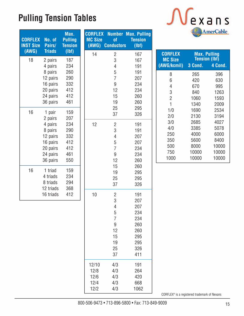
Pulling Tension Tables
Max.CORFLEX No. of PullingINST Size Pairs/ Tension(AWG) Triads (lbf)
18 2 pairs 1874 pairs 2348 pairs 26012 pairs 29016 pairs 33220 pairs 41224 pairs 41236 pairs 461
16 1 pair 1592 pairs 2074 pairs 2348 pairs 29012 pairs 33216 pairs 41220 pairs 41224 pairs 46136 pairs 550
16 1 triad 1594 triads 2348 triads 29412 triads 36816 triads 412
CORFLEXMC Size
(AWG/kcmil) 3 Cond. 4 Cond.
8 265 3966 420 6304 670 9953 840 12632 1060 15931 1340 2009
1/0 1690 25342/0 2130 31943/0 2685 40274/0 3385 5078250 4000 6000350 5600 8400500 8000 10000750 10000 10000
1000 10000 10000
CORFLEX Number Max. PullingMC Size of Tension(AWG) Conductors (lbf)
14 2 1673 1674 1915 1917 2079 23412 23415 26019 26025 29537 326
12 2 1913 1914 2075 2077 2349 23412 26015 26019 29525 29537 326
10 2 1913 2074 2075 2347 2349 26012 26015 29519 29525 32637 411
12/10 4/3 19112/8 4/3 26412/6 4/3 42012/4 4/3 66812/2 4/3 1062
Max. PullingTension (lbf)
CORFLEX® is a registered trademark of Nexans
16 www. nexansamercable.com • e-mail: [email protected]
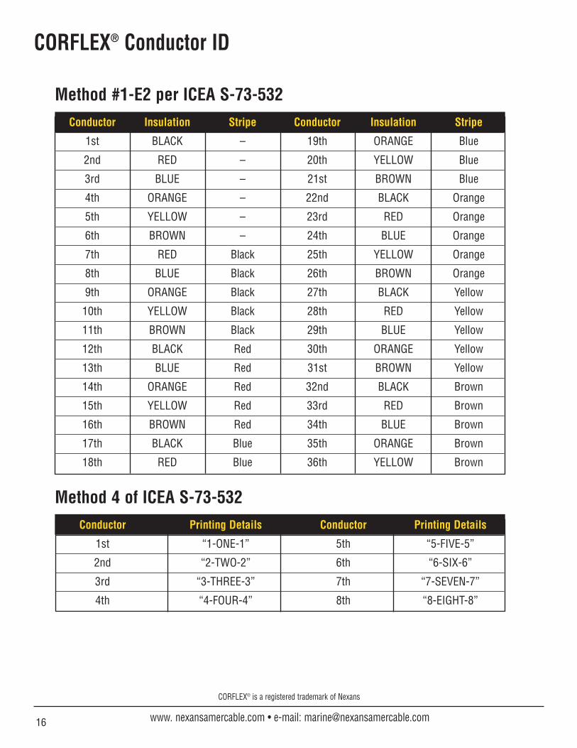
CORFLEX® Conductor ID
Conductor Insulation Stripe Conductor Insulation Stripe
1st BLACK – 19th ORANGE Blue
2nd RED – 20th YELLOW Blue
3rd BLUE – 21st BROWN Blue
4th ORANGE – 22nd BLACK Orange
5th YELLOW – 23rd RED Orange
6th BROWN – 24th BLUE Orange
7th RED Black 25th YELLOW Orange
8th BLUE Black 26th BROWN Orange
9th ORANGE Black 27th BLACK Yellow
10th YELLOW Black 28th RED Yellow
11th BROWN Black 29th BLUE Yellow
12th BLACK Red 30th ORANGE Yellow
13th BLUE Red 31st BROWN Yellow
14th ORANGE Red 32nd BLACK Brown
15th YELLOW Red 33rd RED Brown
16th BROWN Red 34th BLUE Brown
17th BLACK Blue 35th ORANGE Brown
18th RED Blue 36th YELLOW Brown
Method #1-E2 per ICEA S-73-532
Method 4 of ICEA S-73-532
Conductor Printing Details Conductor Printing Details
1st “1-ONE-1” 5th “5-FIVE-5”
2nd “2-TWO-2” 6th “6-SIX-6”
3rd “3-THREE-3” 7th “7-SEVEN-7”
4th “4-FOUR-4” 8th “8-EIGHT-8”

1_14© 2014, AmerCable Incorporated
The industrystandard forflexible, highquality power,control andinstrumentationType P cables.
Crush andImpactResistant Type P cableswithoutexternalarmoring
Low smokehalogen-freefire resistantor flameretardant Type P cables
Precisionengineered cableassembliesfor hazardousand industrialapplications
Foil shielded, power cablesengineered for use in variablefrequency AC driveapplications.
Available in severalconstructions
Top DriveService Loops
Nexans AmerCable is an ISO 9001 certified cablemanufacturer that combines leading-edge manufacturing
technology, innovative thinking, and high qualityservice to deliver the finest oil & gas cable andengineered cable assemblies available.
Nexans AmerCable serves the world fromour Oil & Gas Group headquarters in Houston, Texas. Our professional field engineers and sales force work withyou to create innovative, cost-effective project solutions.
10633 West Little York • Building #1 • Suite #100 • Houston, TX 77041 800-506-9473 • 713-896-5800 • Fax: 713-849-9009 • e-mail: [email protected]
www.nexansamercable.com
What can you expect fromNexans AmerCable?n Best at On-Time Delivery
n Outstanding Engineering Supportand Customer Service
n Innovative Productivity Solutions
n Global Cable Management