Embed Size (px)
Citation preview

GH5200 User Manual V1.0

2
Table of contents 1 INTRODUCTION ................................................................................................................... 7
1.1 ATTENTION ............................................................................................................................ 7 1.2 BRIEF DESCRIPTION .................................................................................................................. 8 1.3 LEGAL NOTICE ........................................................................................................................ 8 1.4 ABOUT DOCUMENT ................................................................................................................. 8
2 BASIC DESCRIPTION .......................................................................................................... 11
2.1 PACKAGE CONTENTS .............................................................................................................. 11 2.2 BASIC CHARACTERISTICS ......................................................................................................... 11 2.3 TECHNICAL FEATURES............................................................................................................. 12 2.4 TECHNICAL INFORMATION ABOUT INTERNAL BATTERY................................................................... 12 2.5 ELECTRICAL CHARACTERISTICS .................................................................................................. 13
3 CONNECTION .................................................................................................................... 14
3.1 HOW TO INSERT SIM CARD AND CONNECT THE BATTERY INTO GH5200 DEVICE: ............................... 14 3.2 INSTALLING GH5200 DRIVERS ................................................................................................ 15
4 OPERATIONAL BASICS ....................................................................................................... 17
4.1 OPERATIONAL PRINCIPLES ....................................................................................................... 17 4.2 SLEEP MODES ....................................................................................................................... 17
4.2.1 GPS Sleep mode ......................................................................................................... 17 4.2.2 Deep Sleep mode ....................................................................................................... 17 4.2.3 Online Deep Sleep mode ............................................................................................ 18 4.2.4 Ultra Deep Sleep mode .............................................................................................. 18
4.3 FEATURES ............................................................................................................................ 18 4.3.1 Alarm ......................................................................................................................... 18 4.3.2 ManDown .................................................................................................................. 19 4.3.3 OverSpeeding ............................................................................................................. 19 4.3.4 Movement Event ........................................................................................................ 19
4.4 VOICE CALL .......................................................................................................................... 19 4.5 TRACKING ON/OFF ............................................................................................................... 20 4.6 BLUETOOTH ......................................................................................................................... 20 4.7 AUTO GEOFENCE .................................................................................................................. 20 4.8 MANUAL GEOFENCE .............................................................................................................. 20 4.9 USER INTERFACE ................................................................................................................... 20 4.10 KEYBOARD ........................................................................................................................... 20
5 CONFIGURATION ............................................................................................................... 20
5.1 CONFIGURATOR .................................................................................................................... 20 5.1.1 Main Buttons description: ......................................................................................... 22 5.1.2 Keyword SMS (GPRS) commands: .............................................................................. 22 5.1.3 Keyword configuration with TCP ............................................................................... 22
5.2 STATUS INFO ........................................................................................................................ 23 5.3 SECURITY INFO ..................................................................................................................... 23 5.4 SYSTEM SETTINGS.................................................................................................................. 24 5.5 GPRS ................................................................................................................................. 26 5.6 SMS/CALL SETTINGS ............................................................................................................. 27 5.7 GSM OPERATORS, ROAMING, BLACKLIST OPERATOR LIST ............................................................ 28 5.8 DATA ACQUISITION MODE SETTINGS ........................................................................................ 30 5.9 FEATURES SETTINGS ............................................................................................................... 34
5.9.1 Alarm ......................................................................................................................... 34 5.9.2 Over Speeding ............................................................................................................ 35 5.9.3 ManDown .................................................................................................................. 35 5.9.4 Movement Event ........................................................................................................ 36
5.10 AUTOGEOFENCING SETTINGS .................................................................................................. 36

3
5.11 MANUAL GEOFENCE .............................................................................................................. 37 5.12 BLUETOOTH ......................................................................................................................... 39
5.12.1 General functionality ................................................................................................. 39 5.12.2 How to connect Bluetooth Hands Free adapter to GH5200 device ........................... 40
5.12.2.1 Bluetooth settings configuration ...................................................................................... 40 5.12.2.2 Connecting Bluetooth Hands Free adapter ...................................................................... 42
5.12.3 Logging the GH5200 device using your mobile phone .............................................. 42 5.12.4 Device debug over Android smartphone ................................................................... 43
5.13 SMS EVENTS ........................................................................................................................ 45 5.14 SMS TEXT ........................................................................................................................... 46 5.15 I/O SETTINGS ....................................................................................................................... 47
5.15.1 Operand On Exit ........................................................................................................ 48 5.15.2 Operand On Entrance ................................................................................................ 48 5.15.3 Operand On Both ...................................................................................................... 48 5.15.4 Operand Monitoring ................................................................................................. 49 5.15.5 Operand On Hysteresis .............................................................................................. 49 5.15.6 Operand On Change .................................................................................................. 49 5.15.7 Operand On Delta Change ........................................................................................ 50 5.15.8 Avg const (Averaging parameter description)........................................................... 50
5.16 USER INTERFACE ................................................................................................................... 51 5.17 KEYBOARD ........................................................................................................................... 55
6 SMS/GPRS COMMAND LIST .............................................................................................. 56
6.1 SMS/GPRS COMMAND LIST................................................................................................... 56 6.1.1 getinfo ....................................................................................................................... 58 6.1.2 getver ......................................................................................................................... 59 6.1.3 getstatus .................................................................................................................... 59 6.1.4 getgps ........................................................................................................................ 59 6.1.5 ggps ........................................................................................................................... 60 6.1.6 getparam ................................................................................................................... 60 6.1.7 setparam .................................................................................................................... 60 6.1.8 flush #,#,#,#,#,#,#....................................................................................................... 60 6.1.9 countrecs ................................................................................................................... 61 6.1.10 deleterecords ............................................................................................................. 61 6.1.11 battery ....................................................................................................................... 61 6.1.12 btgetlist # .................................................................................................................. 61 6.1.13 setkey # # .................................................................................................................. 62 6.1.14 delkey # # .................................................................................................................. 62 6.1.15 bbread # .................................................................................................................... 62 6.1.16 bbinfo # ..................................................................................................................... 62 6.1.17 sdformat .................................................................................................................... 62
7 PARAMETER LIST ............................................................................................................... 63
7.1 SYSTEM PARAMETERS ............................................................................................................ 63 7.1.1 Sleep Mode (ID=102) ................................................................................................. 63 7.1.2 Sleep timeout (ID=103) .............................................................................................. 63 7.1.3 Static Navigation (ID=106) ......................................................................................... 63 7.1.4 Saving/Sending without time synchronization (ID=107) ........................................... 63 7.1.5 GNSS Source (ID=109) ................................................................................................ 63 7.1.6 Synchronization settings (ID=900) ............................................................................. 64 7.1.7 NTP Resync (ID=901) .................................................................................................. 64 7.1.8 NTP server 1 (ID=902) ................................................................................................ 64 7.1.9 NTP server 2 (ID=903) ................................................................................................ 64
7.2 GPRS PARAMETERS .............................................................................................................. 65 7.2.1 Sorting (ID=1002) ....................................................................................................... 65 7.2.2 Open Link Timeout (ID=1000) .................................................................................... 65 7.2.3 Server Response Timeout (ID=1001) .......................................................................... 65 7.2.4 SIM GPRS content activation (ID=2000) .................................................................... 65

4
7.2.5 SIM APN Name (ID=2001) .......................................................................................... 66 7.2.6 SIM APN Username (ID=2002) ................................................................................... 66 7.2.7 SIM APN Password (ID=2003) .................................................................................... 66 7.2.8 Domain (ID=2004) ...................................................................................................... 66 7.2.9 Target Server Port (ID=2005) ..................................................................................... 66 7.2.10 Protocol (ID=2006) .................................................................................................... 67 7.2.11 Backup Server Domain (ID=2007) ............................................................................. 67 7.2.12 Backup Server Port (ID=2008) ................................................................................... 67 7.2.13 Backup Server Protocol (ID=2009) ............................................................................. 67 7.2.14 Backup Server Mode (ID=2010) ................................................................................. 67 7.2.15 FOTA WEB status (ID=13003) .................................................................................... 67 7.2.16 FOTA WEB Domain (ID=13000) ................................................................................. 68 7.2.17 FOTA WEB port (ID=13001) ...................................................................................... 68 7.2.18 FOTA WEB Period (min) (ID=13002) .......................................................................... 68
7.3 SMS/CALL SETTINGS ............................................................................................................. 68 7.3.1 SMS data sending settings (ID=3000) ........................................................................ 68 7.3.2 Data send number (ID=3001)..................................................................................... 68 7.3.3 Authorized phone numbers (ID=4000-4199).............................................................. 69 7.3.4 GSM Predefined Numbers (ID=6000-6009)................................................................ 69 7.3.5 SMS Login (ID=3003) .................................................................................................. 69 7.3.6 SMS Password (ID=3004) ........................................................................................... 69 7.3.7 Incoming call action (ID=3005) .................................................................................. 69 7.3.8 SMS Event Time Zone (ID=3006) ................................................................................ 70 7.3.9 Detect Number Type By Plus Symbol (ID=4999) ........................................................ 70
7.4 GSM OPERATORS ................................................................................................................. 70 7.4.1 SIM Roaming Operator List (ID=5000-5049) .............................................................. 70 7.4.2 Black List (ID=5500-5549) .......................................................................................... 70
7.5 DATA ACQUISITION MODES PARAMETERS .................................................................................. 71 7.5.1 Home Network GSM operator code “Vehicle on STOP” parameters ......................... 71
7.5.1.1 Min Period (ID=10000) ....................................................................................................... 71 7.5.1.2 Min Saved Records (ID=10004) .......................................................................................... 71 7.5.1.3 Send Period (ID=10005) ...................................................................................................... 71
7.5.2 Home Network GSM operator code “Vehicle MOVING” parameters ........................ 71 7.5.2.1 Min Period (ID=10050) ....................................................................................................... 71 7.5.2.2 Min Distance (ID=10051) .................................................................................................... 71 7.5.2.3 Min Angle (ID=10052) ......................................................................................................... 72 7.5.2.4 Min Speed Delta (ID=10053) .............................................................................................. 72 7.5.2.5 Min Saved Records (ID=10054) .......................................................................................... 72 7.5.2.6 Send Period (ID=10055) ...................................................................................................... 72
7.5.3 Roaming Network GSM operator code “Vehicle on STOP” parameters .................... 73 7.5.3.1 Min Period (ID=10100) ....................................................................................................... 73 7.5.3.2 Min Saved Records (ID=10104) .......................................................................................... 73 7.5.3.3 Send Period (ID=10105) ...................................................................................................... 73
7.5.4 Roaming Network GSM operator code “Vehicle MOVING” parameters ................... 73 7.5.4.1 Min Period (ID=10150) ....................................................................................................... 73 7.5.4.2 Min Distance (ID=10151) .................................................................................................... 74 7.5.4.3 Min Angle (ID=10152) ......................................................................................................... 74 7.5.4.4 Min Speed Delta (ID=10153) .............................................................................................. 74 7.5.4.5 Min Saved Records (ID=10154) .......................................................................................... 74 7.5.4.6 Send Period (ID=10155) ...................................................................................................... 75
7.5.5 Unknown Network GSM operator code “Vehicle on STOP” parameters ................... 75 7.5.5.1 Min Period (ID=10200) ....................................................................................................... 75 7.5.5.2 Min Saved Records (ID=10204) .......................................................................................... 75 7.5.5.3 Send Period (ID=10205) ...................................................................................................... 75
7.5.6 Unknown Network GSM operator code “Vehicle MOVING” parameters .................. 75 7.5.6.1 Min Period (ID=10250) ....................................................................................................... 75 7.5.6.2 Min Distance (ID=10251) .................................................................................................... 76 7.5.6.3 Min Angle (ID=10252) ......................................................................................................... 76 7.5.6.4 Min Speed (ID=10253) ........................................................................................................ 76 7.5.6.5 Min Saved Records (ID=10254) .......................................................................................... 77

5
7.5.6.6 Send Period (ID=10255) ...................................................................................................... 77 7.6 FEATURES PARAMETERS ......................................................................................................... 77
7.6.1 Alarm ......................................................................................................................... 77 7.6.1.1 Scenario Settings (ID=11710).............................................................................................. 77 7.6.1.2 Send SMS To (ID=7245) ...................................................................................................... 77 7.6.1.3 SMS Text (ID=8245) ............................................................................................................ 77 7.6.1.4 Call Settings (ID=11711) ..................................................................................................... 78 7.6.1.5 Call to (ID=11712) ............................................................................................................... 78
7.6.2 Overspeeding scenario parameters ........................................................................... 78 7.6.2.1 Overspeeding priority (ID=11100) ...................................................................................... 78 7.6.2.2 Max Speed (ID=11104) ....................................................................................................... 78 7.6.2.3 Overspeeding Send SMS To (ID=7032) ............................................................................... 78 7.6.2.4 Overspeeding SMS Text (ID=8032) ..................................................................................... 79
7.6.3 ManDown scenario parameters ................................................................................ 79 7.6.3.1 Scenario Settings (ID=12100).............................................................................................. 79 7.6.3.2 Position (ID=12100) ............................................................................................................ 79 7.6.3.3 Angle (ID=12102) ................................................................................................................ 79 7.6.3.4 Timeout (ID=12103) ............................................................................................................ 79 7.6.3.5 Send SMS To (ID=7222) ...................................................................................................... 79 7.6.3.6 SMS Text (ID=8222) ............................................................................................................ 79 7.6.3.7 Call Settings (ID=12104) ..................................................................................................... 80 7.6.3.8 Call to (ID=12105) ............................................................................................................... 80
7.7 AUTOGEOFENCING SCENARIO PARAMETERS ............................................................................... 80 7.7.1 AutoGeofencing priority (ID=20000) .......................................................................... 80 7.7.2 Eventual Records (ID=20002) ..................................................................................... 80 7.7.3 AutoGeofence event generating (ID=20001) ............................................................. 81 7.7.4 Radius (ID=20004) ..................................................................................................... 81 7.7.5 AutoGeofence Send SMS to (ID=7030)....................................................................... 81 7.7.6 SMS Text (ID=8030) ................................................................................................... 81 7.7.7 Call Settings (ID=12104) ............................................................................................ 82 7.7.8 Call to (ID=12105) ...................................................................................................... 82
7.8 MANUAL GEOFENCE .............................................................................................................. 82 7.8.1 First Geozone parameters .......................................................................................... 82
7.8.1.1 #1 Geozone Manual Geofencing priority (ID=20100): ........................................................ 82 7.8.1.2 #1 Geozone Manual Geofence event generating (ID=20101) ............................................ 83 7.8.1.3 #1 Geozone Eventual Records (ID=20102) ......................................................................... 83 7.8.1.4 #1 Geozone Frame border (ID=20103) ............................................................................... 83 7.8.1.5 #1 Geozone Shape type (ID=20104) ................................................................................... 84 7.8.1.6 #1 Geozone Radius (ID=20105).......................................................................................... 84 7.8.1.7 #1 Geozone X1 (ID=20106) ................................................................................................. 85 7.8.1.8 #1 Geozone Y1 (ID=20107) ................................................................................................. 85
7.8.2 Other Geozones ......................................................................................................... 86 7.8.2.1 Send SMS to #1-5 Geozone (ID=7025-7029), #6-50 Geozone (ID=7071-7115).................. 86 7.8.2.2 SMS Text #1-5 Geozone (ID=8025-8029), #6-50 Geozone (ID=8071-8115) ....................... 86
7.9 USER INTERFACE ................................................................................................................... 87 7.9.1 Indication Scenario (12500) ....................................................................................... 87 7.9.2 Sleep Config (12501) .................................................................................................. 87 7.9.3 Led (12502) ................................................................................................................ 87 7.9.4 Vibration (12503) ....................................................................................................... 87 7.9.5 Period (12504) ........................................................................................................... 87 7.9.6 On (ms) (12505) ......................................................................................................... 87 7.9.7 Off (ms) (12506) ......................................................................................................... 88 7.9.8 Repeat (12507) .......................................................................................................... 88
7.10 KEYBOARD ........................................................................................................................... 91 7.11 ACTIONS ............................................................................................................................. 93
7.11.1 SMS Action ................................................................................................................ 93 7.11.1.1 SMS Send to (7249) .......................................................................................................... 93 7.11.1.2 SMS Text (8249) ................................................................................................................ 93
7.11.2 Call Action ................................................................................................................. 93 7.11.2.1 Call to (13010) .................................................................................................................. 93
7.12 BLUETOOTH ......................................................................................................................... 93

6
7.12.1.1 BT Radio (ID=800) ............................................................................................................. 93 7.12.1.2 Local name (ID 801) .......................................................................................................... 93 7.12.1.3 Local PIN (ID=802) ............................................................................................................ 94 7.12.1.4 Security mode (ID=803) .................................................................................................... 94 7.12.1.5 External MAC (ID=804) ..................................................................................................... 94 7.12.1.6 External name (ID=805) .................................................................................................... 95 7.12.1.7 External PIN (ID=806) ....................................................................................................... 95 7.12.1.8 Connection mode (ID=807) .............................................................................................. 95 7.12.1.9 Authorized devices MAC list (ID=830 - 834) ..................................................................... 96
7.13 I/O PARAMETERS .................................................................................................................. 96 7.13.1 I/O#1 property parameter priority (ID=50010) ......................................................... 96 7.13.2 I/O#1 operand (ID=50011) ........................................................................................ 96 7.13.3 I/O#1 High level (ID=50012) ...................................................................................... 97 7.13.4 I/O#1 Low level (ID=50013) ....................................................................................... 97 7.13.5 I/O#1 Event only (ID=50014) ..................................................................................... 97 7.13.6 I/O#1 averaging length (ID=50015) .......................................................................... 98 7.13.7 I/O#1 send SMS (ID=7001) ........................................................................................ 98 7.13.8 I/O#1 SMS text (ID=8001).......................................................................................... 98 7.13.9 I/O elements parameters and types .......................................................................... 99
8 DEBUG MODE ................................................................................................................. 104
9 CHANGE LOG ................................................................................................................... 105

7
1 INTRODUCTION
1.1 Attention
Operate the device in suitable conditions Do not use the device where mobile connectivity is forbidden.
Road safety first Comply with local traffic laws, always hold your hands on a steering wheel when using a device. Your safety is of utmost importance when you drive.
Interference All wireless devices are sensitive to electromagnetic interference, as a result wireless devices affect the performance of each other.
Limit the use of device in hospitals Please follow all restrictions. Turn off the device in the vicinity of medical devices when required.
Limit the use of device in vehicles Please follow all restrictions. Wireless devices can interfere with other electronic equipment in vehicles.
Be cautious near flammable materials and liquids
Charging precautions SELV LPS chargers, personal computers or laptops that device will be connected to must comply with the requirements of IEC 60950:2005 standard.
Use only original batteries Using uncertified manufacturer or different type batteries may cause an explosion.
Use batteries safely Protect batteries from moisture. Place them in a cool and dry place when storing. Avoid extensive operation at high temperatures. Do not attempt charging battery directly from the electrical mains. All utilised batteries shall comply with IEC 62133.
Power supplies Power supply circuits used to charge the device connection must have safeguards, which prevent power leakage, short circuits or incorrect electrical grounding. Any used switches ought to be installed in a readily accessible location. Power must be uninterrupted and the distance between the contacts must be 3 mm or larger.
Remove device safely Device must be disconnected from computer or charger by unplugging the magnetic USB cable from the device.

8
Other In order to prevent device from mechanical damage it is advisable to transport it in a shock–resistant packaging. If device stopped working properly regardless of the settings only a qualified specialist can help. It is recommended to contact your local seller or your UAB Teltonika manager in such case.
1.2 Brief description
GH5200 is a handheld tracking device with built-in functions and characteristics of a mobile phone. This device is intended for the surveillance and protection of people, cargo and valuables. GNSS receiver is able to identify current location and send it to an operations center or a person. In case of an emergency the device can activate the alarm function or make a voice call. Device is able to execute various tasks through GSM network and GNSS system. Easy installation, operation and user friendly design will help perform the user’s desired tasks easier.
1.3 Legal Notice
Copyright © 2019 Teltonika. All rights reserved. Reproduction, transfer, distribution or storage of part or all of the contents in this document in any form without the prior written permission of Teltonika is prohibited.
Other products and company names mentioned here may be trademarks or trade names of their respective owners.
The manufacturer reserves the right to make changes and/or improvements at any time in design, functionality, parameters and electrical characteristics without any prior notice and without incurring obligations.
1.4 About document
This document contains information about the architecture, possibilities, mechanical characteristics, and configuration of the GH5200 device.
Acronyms and terms used in this document: ▪ AC/DC – Alternating Current/Direct Current ▪ ACC – Accessories ▪ AVL - Automatic vehicle location: means for automatically determining and transmitting
the geographic location of a vehicle. ▪ AVL packet: Data packet which is being sent to the server during data transmission. ▪ APN - Access Point Name: the name of a gateway between 3GPP mobile network and
Internet or another computer network. ▪ CAN - Controller Area Network: a vehicle bus standard designed to allow microcontrollers
and devices to communicate with each other in applications without a host computer. ▪ CNG - Compressed Natural Gas: methane stored at high pressure. ▪ COM port - serial communication interface that is used to transfer information to/from
devices such as modems, terminals and various peripherals. ▪ DTC - Diagnostic Trouble Code ▪ ESP - Electronic Stability Program: is a technology that improves a vehicle's stability by
detecting and reducing loss of traction (skidding). ▪ ETA - Estimated Time of Arrival ▪ FAP - Particulate Filter ▪ FOTA - Firmware-Over-The-Air

9
▪ GNSS – Global Navigation Satellite System: a system with global coverage that uses satellites to provide autonomous geo-spatial positioning.
▪ GPS – Global Positioning System: a worldwide satellite navigational system formed by 24 satellites orbiting the earth and their corresponding receivers on the earth.
▪ GPRS – General Packet Radio Service: a standard for wireless communications which runs at speeds up to 115 kilobits per second.
▪ GSM – Global System for Mobile Communications: one of the leading digital cellular systems. GSM uses narrowband TDMA, which allows eight simultaneous calls on the same radio frequency.
▪ I/O – Input/Output ▪ ICCID - Integrated Circuit Card Identifier: a unique serial number that is stored on the SIM
card. ▪ IMEI - International Mobile Equipment Identity: is a unique number that is used to
identify 3GPP mobile phones. ▪ LED - Light Emitting Diode ▪ MAC – Media Access Control. Hardware address which uniquely identifies each node of
the network. In IEEE 802 networks, the Data Link Control (DCL) layer of the PSO Reference Model is divided into two sub-layers: the Logical Link Control (LLC) layer and the Media Access Control layer. The MAC layer interfaces directly with the network medium. Consequently, each different type of network medium requires a different MAC layer.
▪ MAF - Mass Airflow Sensor: a device used to measure the mass flow rate of air entering a fuel-injected internal combustion engine.
▪ NITZ - Network Identity and Time Zone: a mechanism for provisioning local time and date, time zone and DST offset, as well as network provider identity information, to mobile devices via a wireless network.
▪ NMEA: a data specification for communication between electronics such as echo sounder, sonars, anemometer, gyrocompass, autopilot, GPS receivers.
▪ NTP - Network Time Protocol: networking protocol for clock synchronization between computer systems over packet-switched, variable-latency data networks.
▪ OBD - On-board Diagnostics: a vehicle's self-diagnostic and reporting capability, which gives access to the status of the various vehicle subsystems.
▪ PC – Personal Computer ▪ PCB - Printed Circuit Board ▪ PIN - Personal Identification Number ▪ RFID - Radio-Frequency Identification: a method that uses electromagnetic fields to
automatically identify and track tags attached to objects. ▪ RPM - Engine Revolutions Per Minute ▪ RTC - Real-Time Clock ▪ SELV - Safety Extra Low Voltage: an electrical system in which the voltage cannot exceed
50 VAC or 120 VDC under normal conditions, and under single-fault conditions, including earth faults in other circuits.
▪ SMS – Short Message Service: the transmission of short text messages to and from a mobile phone, fax machine and/or IP address.
▪ SIM - Subscriber Identification Module: an integrated circuit card that is intended to securely store the information which is used to identify and authenticate subscribers on mobile telephony devices.
▪ TCP – Transmission Control Protocol – one of the main protocols in TCP/IP networks. Whereas the IP protocol deals only with packets, TCP enables two hosts to establish a

10
connection and exchange streams of data. TCP guarantees delivery of data and also guarantees that packets will be delivered in the same order in which they were sent.
▪ TMO - Timeout ▪ UDP – User Datagram Protocol – a connectionless protocol that, like TCP, runs on top of
IP networks. Provides very few error recovery services, offering instead a direct way to send and receive datagrams over IP network.
▪ Record – AVL data stored in FMB memory. AVL data contains GNSS and I/O information.

11
2 BASIC DESCRIPTION
GH5200 is an AUTONOMOUS personal tracker with GNSS, GSM and Bluetooth connectivity, device has high quality voice communication feature and modern slim design.
The tracker is designed for Lone Worker protection. Everyone who performs activity without close or direct supervision of others: healthcare visitors, maintenance workers, self-employed or working out of standard work hours employees.
2.1 Package contents
The GH5200 device is supplied to the customer in a cardboard box containing all the
equipment that is necessary for operation. The package contains: ▪ GH5200 device; ▪ 3.7 V 1050 mAh rechargeable Li-ion battery; ▪ Micro USB cable; ▪ Screw driver.
2.2 Basic characteristics
GSM / GPRS / GNSS features: ▪ Teltonika TM2500 quad band module (GSM 850 / 900 / 1800 / 1900 MHz); ▪ GPRS class 12 (Up to 240 kbps); ▪ SMS (text, data); ▪ Integrated GNSS receiver; ▪ Up to -165 dBm GNSS receiver sensitivity.
Hardware features: ▪ Built-in accelerometer; ▪ Panic button; ▪ Built-in Bluetooth 3.0 and 4.0); ▪ Internal High Gain GNSS antenna; ▪ Internal High Gain GSM antenna; ▪ 1050 mAh Li-ion rechargeable 3.7 V battery. ▪ Slim casing; ▪ Magnetic USB cable.
Firmware features: ▪ Fast position fix; ▪ Two way voice communication; ▪ Man-down detection; ▪ 50 Manual Geofence zones; ▪ Auto Geofencing; ▪ Action on call feature; ▪ Configurable 3 LED status indication; ▪ Authorized numbers; ▪ Time synchronization over NTP and NITZ; ▪ Real time tracking; ▪ Smart data acquisition based on:

12
o Time; o Speed; o Angle; o Distance; o Movement or any other I/O event;
▪ Sending acquired data via GPRS; ▪ GPRS and SMS I/O events; ▪ Configurable using Secured SMS Commands.
2.3 Technical features
Part name Physical specification Technical details
LED 3 status LEDs Energy consumption1:
GPRS: average 52.31 mA; Nominal: average 45.10 mA; GNSS Sleep: average 10.12 mA; Deep Sleep: average 3.02 mA; Online Deep Sleep: average 3.78 mA; Ultra Deep Sleep: average 1.82 mA.
Battery charge current:
average 733 mA; Operation temperature:
-25 °C .. +65 °C Storage temperature:
-40 °C .. +70 °C Storage relative humidity:
5 .. 95 % (no condensation)
USB Micro USB socket
GNSS Internal GNSS antenna
GSM Internal GSM antenna
Microphone and speader
Internal microphone and speader
BUTTON 5 configurable buttons
2.4 Technical Information about internal battery
Table 1. Li –ion rechargeable battery, 3.7 V, 1050 mAh.
Internal back-up battery
Battery voltage V Nominal capacity (mAh) Power (Wh) Charging temperature °C
Li-ion rechargeable battery
3.70 1050 3.885 0 – 45
1 Energy consumption has been tested by running GH5200 on battery (4.2 V).

13
CAUTION: RISK OF EXPLOSION IF BATTERY IS REPLACED BY AN INCORRECT TYPE. DISPOSE OF USED BATTERIES ACCORDING TO THE INSTRUCTIONS.
Battery Disposal instructions:
Battery should not be disposed of into general household waste. Bring damaged or worn-out batteries to your local recycling center or dispose them into a battery recycle bin commonly found in supermarkets.
Warranty: batteries are covered by 6 months warranty support.
2.5 Electrical characteristics
Table 2. GH5200 electrical characteristics
Characteristic description
Value
Supply Voltage: Min. Typ. Max. Unit
In recommended operating conditions 4.5 5.0 5.5 V DC

14
3 CONNECTION
3.1 How to insert SIM card and connect the battery into GH5200 device:
Remove GH5200 cover.
Insert Micro SIM card as shown. Battery has to be disconnected at this point.
Insert the battery.
Reatach the cover and tighten the srew
Note: SIM card insertion/removal must be performed when GH5200 device is powered off – with external voltage and battery disconnected. Otherwise SIM card may be damaged.
15
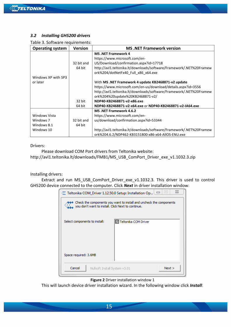
3.2 Installing GH5200 drivers
Table 3. Software requirements:
Operating system Version MS .NET Framework version
Windows XP with SP3 or later
32 bit and 64 bit
32 bit 64 bit
MS .NET Framework 4 https://www.microsoft.com/en-US/Download/confirmation.aspx?id=17718 http://avl1.teltonika.lt/downloads/software/Framework/.NET%20Framework%204/dotNetFx40_Full_x86_x64.exe
With MS .NET Framework 4 update KB2468871-v2 update https://www.microsoft.com/en-us/download/details.aspx?id=3556 http://avl1.teltonika.lt/downloads/software/Framework/.NET%20Framework%204%20update%20KB2468871-v2/ NDP40-KB2468871-v2-x86.exe NDP40-KB2468871-v2-x64.exe or NDP40-KB2468871-v2-IA64.exe
Windows Vista Windows 7 Windows 8.1 Windows 10
32 bit and 64 bit
MS .NET Framework 4.6.2 https://www.microsoft.com/en-us/download/confirmation.aspx?id=53344
http://avl1.teltonika.lt/downloads/software/Framework/.NET%20Framework%204.6.2/NDP462-KB3151800-x86-x64-AllOS-ENU.exe
Drivers:
Please download COM Port drivers from Teltonika website: http://avl1.teltonika.lt/downloads/FMB1/MS_USB_ComPort_Driver_exe_v1.1032.3.zip
Installing drivers:
Extract and run MS_USB_ComPort_Driver_exe_v1.1032.3. This driver is used to control GH5200 device connected to the computer. Click Next in driver installation window:
Figure 2 Driver installation window 1
This will launch device driver installation wizard. In the following window click Install:

16
Figure 3 Driver installation window 2
Setup will continue installing drivers and eventually the confirmation window will appear.
Click Close to complete the setup:
Figure 4 Driver installation window 3
You are now ready to use the device on your computer.

17
4 OPERATIONAL BASICS
4.1 Operational principles
GH5200 module is designed to acquire records and send them to the server. Records contain GNSS data and I/O information. Module uses GNSS receiver to acquire GNSS data and is run in three (time-based, distance-based and angle-based) acquisition modes. Please note that if GH5200 loses connection to GNSS satellites it continues to make records, however coordinate in these records remains the same (last known coordinate). All data is stored into flash memory and later can be transmitted via GPRS.
GPRS and SMS settings are described in following sections. GH5200 communicates with server using Codec 8 data protocol. GH5200 can be managed by SMS commands, which are described in SMS command section.
4.2 Sleep modes
There are four sleep modes: GPS sleep, Deep sleep, Online Deep sleep and Ultra Deep sleep mode.
4.2.1 GPS Sleep mode
GH5200 is able to go into GPS sleep mode if such mode is enabled. Sleep mode timeout starts counting when device is in STOP mode. After timeout is reached
and all conditions for GPS sleep mode are met, the device goes into sleep mode. When in GPS sleep mode, GH5200 turns GPS module off and continues making new periodic records.
GH5200 will enter GPS sleep mode if ALL of these conditions are met: ▪ GH5200 is configured to work in GPS Sleep mode and sleep timeout is reached; ▪ Device time is synchronized with GNSS satellites and GPS fix is obtained; ▪ Movement is not detected by the accelerometer; ▪ Forced wakeup is not set; ▪ There are no SMS messages being received.
GH5200 exits GPS sleep mode if following condition is true: ▪ Movement by accelerometer is detected.
4.2.2 Deep Sleep mode
When in deep sleep mode, GH5200 sets the GNSS receiver to sleep mode and turns off GSM/GPRS module (hence it is not possible to wake up device via SMS). Records with last known coordinate being saved and sent to AVL server - GSM/GPRS module is turned on to send data and then it is turned off. Please note that power saving depends on two configurable parameters: Send Period and Minimum Record Saving Period in "X on Stop Mode". When records are sent successfully in deep sleep mode, open link timeout counter will be skipped and GH5200 will enter deep sleep mode immediately.
Because a lot of functions are disabled in deep sleep mode following I/O elements are disabled from records that are generated in this mode: GSM Signal, GNSS Status, GNSS PDOP,

18
GNSS HDOP, GSM CellID, GSM Area Code, Active GSM Operator and ICCID. GH5200 can enter deep sleep mode if ALL of these conditions are met: ▪ GH5200 is configured in Deep Sleep mode and sleep timeout is reached; ▪ Device time is synchronized with GNSS satellites and GPS fix is obtained; ▪ Movement is not detected by the accelerometer; ▪ Min. Record Saving Period (Data Acquisition Mode settings) must be larger than Open
Link Timeout parameter, so that GH5200 could close GPRS link; ▪ The difference between Send Period (Data Acquisition Mode settings) and Open Link
Timeout must be more than 90 seconds, so that GH5200 could close GPRS link within at least 90 seconds;
▪ Forced wakeup is not set; ▪ There are no SMS messages being received; ▪ Data socket(s) are closed; ▪ Data sending is not in progress; ▪ FOTA is not in progress.
GH5200 exits deep sleep mode if following condition is true:
• Movement by accelerometer is detected;
4.2.3 Online Deep Sleep mode
In this mode the device works as in deep sleep mode, but without deregistering from GSM network. GSM part stays powered so this increases power consumption. In this mode device should send/receive SMS and make/accept calls. It does not close GPRS context if one was previously opened. Conditions to enter online deep sleep mode are the same as entering deep sleep mode. GH5200 exits online sleep mode if following condition is true. GH5200 exits online sleep mode if following condition is true: ▪ Movement by accelerometer is detected;
4.2.4 Ultra Deep Sleep mode
Conditions to enter ultra deep sleep mode, where GPS and GSM modem are turned off and device functions are suspended for maximum battery saving, are the same as entering Deep Sleep mode.
GH5200 exits ultra deep sleep mode only when movement is detected by accelerometer. Movement source is not taken into account in this case.
4.3 Features
Using available features can greatly increase GH5200 utilization.
4.3.1 Alarm
Alarm is a feature that can be only triggered by a pressing the configured button. When the alarm is triggered, an event with IO ID 236 is generated. Following a configured button press to activate the Alarm an SMS can be sent and a call can be performed. Data sending follows in this order: 1. GPRS; 2. SMS; 3. Call.
There are “GPRS and SMS” and “GPRS or SMS” notification methods.

19
If selected method “GPRS or SMS”. At first device tries to connect to GPRS context using configured APN. If it does not connect device sends sms event to configured number.
If method is “GPRS and SMS” SMS will be sent in both cases, when GPRS has failed and when records are sent to server.
These SMS sending methods are valid for these Events: Alarm; Man Down, Movement Event and Over speeding.
4.3.2 ManDown
ManDown functionality gets current accelerometer data and calculates the angle between offset position. Currently there are two positions: horizontal and Scanning is performed each second. When calculated angle exceeds the configured angle value for 3 seconds an event is generated with configured priority, device can make a voice call or send an SMS notification, if it is configured. When the device returns to allowed base position an event with same priority is generated.
4.3.3 OverSpeeding
This functionality prevents exceeding fixed speed limits and inspects the driver if required.
4.3.4 Movement Event
Movement Event functionality makes an eventual high priority record (and sends an optional SMS) when device is stationary or in motion (depending on configured "Mode") for set Timeout (added to "Movement Start/Stop Delays" accordingly).
Timeout is a configured amount of time (in seconds) after which an eventual high priority record is generated.
Note: this timeout is added with Movement Start Delay if configured Mode is Movement Event or with Movement Stop Delay if configured Mode is No Movement Event.
Movement Event mode generates a record after the start of movement whereas No Movement Event generates a record after the stop of movement.
4.4 Voice call
Device has integrated microphone and a speaker, which allows you to perform two voice
call. Voice call is available in normal and loud speaker modes.
Normal speaker mode – when call is answered with low speaker volume, default speaker volume is set to 40%.
Loud speaker Volume. – when call is answered with loud speaker volume, default speaker volume is set to 100%.
Figure 5 Volume control

20
4.5 Tracking On/Off
This keyboard functionality, which turns on and off GNSS module on konfigured key
pressed.
4.6 Bluetooth
Bluetooth can work in two modes - slave or master. When in master mode Bluetooth can connect to the defined hands-free system. When working in slave mode - Bluetooth can accept incoming pairing requests from external devices.
NOTE: GH5200 supports ONE connection at a time. NOTE: GH5200 can see up to 10 available devices. If there are more than 10 devices the scanning list may change.
4.7 Auto Geofence
Auto Geofence is a feature that notifies the user if the object has left the zone that was
generated within set radius around the device. This feature is based on the last known position
after the movement has stopped. More details about Auto Geofencing can be found in chapter
5.10.
4.8 Manual Geofence
Geofencing is another feature which is highly customizable and can detect whenever car enters or leaves customized areas. More details about Geofencing can be found out in chapter 5.11.
4.9 User Interface
This section allows to configure GH5200’s LED, audio and vibration indication for each scenario using the configurator. More information about this can be found in Chapter 5.16
4.10 Keyboard
There are five configurable buttons in GH5200 - Alarm Button, Power Button, 1, 2 and 3 buttons. More information about this can be found in Chapter 5.17
5 CONFIGURATION
5.1 Configurator
At first GH5200 device will have default factory settings set. These settings should be changed according to the user's needs.
Device can be configured to acquire and send data to server, in this case the GSM settings shall be set in regards with GSM operator's information. If device GSM is unavailable, the device will not be able to send the data and GH5200 will start storing records to flash memory. It is possible to store up to 192000 data records within internal memory (when 100 MB are used to

21
store records). It will send data over GPRS when it is available. Note that GH5200 might reach its full memory capacity. If such case happens, the device will start deleting the oldest records in order to save new ones.
GH5200 configuration is performed via GH5200 Configurator program. Contact sales manager to get the latest GH5200 Configurator version.
GH5200 configurator operates on Microsoft Windows OS and uses prerequisite MS .NET Framework.
Module configuration can be performed over Micro USB cable or using a Bluetooth connection. Configuration process begins by starting GH5200 Configurator software and then connecting to GH5200 device via Connect button located in Online menu part. GH5200 has one user editable profile, which can be loaded and saved to the device. After any modification of configuration the changes need to be saved to GH5200 device using Save to device button.
Figure 5 GH5200 configurator window when selecting the connection method
Figure 6 GH5200 configurator main window when connected to it and successfully loaded parameters

22
Figure 7 GH5200 status elements
5.1.1 Main Buttons description:
Load from device – loads configuration from device. Save to device – save configuration to device. Load from file – load configuration from file. Save to file – save configuration to file. Update firmware – update firmware on device. Reset device – reset device configuration to default.
5.1.2 Keyword SMS (GPRS) commands:
Configuration should not be locked when the user is attempting to set a new keyword, change it or delete it. For example:
Set new keyword (set): <SMS login>{space}<SMS pass>{space}setkey{space}{space}<newkeyword>
Change old keyword (change): <SMS login>{space}<SMS pass>{space}setkey{space}<oldkeyword>{space}<newkeyword>
Delete current keyword: <SMS login>{space}<SMS pass>{space}delkey{space}<keyword>
5.1.3 Keyword configuration with TCP
If keyword is set, it will be saved to configuration file.

23
If keyword in configuration file does not match keyword in device after TCP configuration, configurator will ask the device keyword. When device is locked, the keyword cannot be changed with TCP configuration.
5.2 Status info
Status info enables the user to monitor real time information of GH5200. Following fields are displayed: Device Info field, GNSS Info field, GSM Info field, I/O Info field and Maintenance field. User is able to export all of the information to .HTML file using an icon which is at the top right corner of the Device Info area.
Device Info shows device name, firmware version, last device start time, RTC Time, power voltage (mV), device IMEI, internal memory free space, device uptime, battery voltage (mV) and internal battery status.
GNSS Info shows: ▪ Real time GNSS status information: module status (ON, Deep/GPS/Online Sleep mode),
the amount of GNSS packets device received from startup, fix status and the last GNSS fix time.
▪ Satellite information: the amount and type of satellites that are visible, and the amount of satellites used for location positioning.
▪ Location information: latitude, longitude, altitude, angle, HDOP, PDOP and speed. GSM Info shows: ▪ GSM status: modem status, SIM status, GPRS status, actual operator code and GSM signal
level. ▪ GPRS traffic: the amount of data that has been sent and received by the device. ▪ Sockets information: which server domain and port is used. ▪ Records: how many records were sent to the server since last data reset, when the last
record was sent and when the last server response was. ▪ SMS count: the amount of SMS messages GH5200 has received and the amount of SMS
responses that were sent from the device. I/O Info shows:
• Values from all configurable I/O elements. Maintenance shows:
• A “log” option to start capturing log for a set amount of time. Log will be saved to directory set in settings.
• A “Dump” option to start downloading logs from currently connected device. Files will be saved to directory set in settings.
• A “Read” option to start capturing accelerometer data for a set amount of time. Log will be saved to directory set in settings.
5.3 Security info
In security section user can see SIM card and configurator keyword security information. ▪ The state and status of currently inserted SIM card can be observed here. If a SIM card
with PIN code is used, user can enter it in this section. The remaining attempts to enter PIN code are shown as well.

24
▪ When SIM PIN code is entered correctly user can change PIN code or disable it from the SIM card. When SIM PIN is disabled and user would like to enable it again, user must enter the previously used PIN code.
▪ Configuration security keyword can be set to configurator. Keyword can be saved in configuration file (.cfg), so there is no need to connect the device to the configurator to configure the keyword. Minimum keyword length is 4 symbols and maximum length is 10 symbols. Only uppercase, lowercase letters and numbers are supported. Keyword can be configured to .cfg configuration file when the device is not connected.
5.4 System settings
System settings have following configurable parameters: ▪ Sleep Settings, where user can choose a sleep mode; ▪ Records saving settings, where user can enable or disable records when GPS is not
available (no time synchronization); ▪ GNSS Source settings, where user can choose the necessary satellite system(s); ▪ Power On By USB/Charger setting. Device supports two working modes: normal mode,
where the device works as usual, and charging mode, which is entered when Power On By USB/Charger parameter is disabled. To enter normal mode, device can be turned on by power button or by USB charger, if Power On By USB/Charger parameter is set to Enable.
▪ Accelerometer Delay Settings, where user can configure movement start and stop delay values (in seconds);
▪ Time Synchronization settings, where user can choose which source(s) to use for GH5200 time synchronization. User has a choice to: use only one synchronization source (Disable (GPS only)), allow synchronization from both the GNSS and NTP server (NTP), select synchronization through GNSS and GSM operator (NITZ) or from all three sources (when NITZ+NTP is selected). User can select which NTP server (it is possible to configure up to two servers) and what time period to use to resynchronize time.
▪ Data Protocol setting – allows user to choose which protocol version to be used for data sending to server.
▪ Sleep Exit Source - allows to select exit from sleep mode method. There are exit sources: Movement and Alarm button.
Power saving mode is present in GH5200. It allows users to choose from two possible
options: 1. Performance mode – High performance mode, where GNSS module is constantly
awake for a maximum track quality (excluding when GH5200 is in sleep mode). 2. Low Power mode – Battery saving mode, where GNSS module is woken up only
when it is time to acquire position. Standard sleep modes are not available in this mode. For this mode to function properly, Min Period in “Data Acquisition” tab has to be >=120 seconds.
Static Navigation mode is a filter, which filters out track jumps when the object is
stationary. If static navigation filter is disabled, it will apply no changes to GPS data. If static navigation filter is enabled, it will filter changes in GPS position if no movement (as defined by

25
configured movement source) is detected. It allows filtering GPS jumps when the object is parked (not moving) and GPS position is still traced.
Figure 8 System settings configuration
GNSS Source settings allows user to configure which GNSS system(s) to use. User has a
choice to use one system between GPS, GLONASS, Galileo or BeiDou and it is possible to choose two or three systems together. One exception is that you cannot combine BeiDou and GLONASS systems together. Below you will find GNSS source combination examples:
List of configurable GNSS sources: BeiDou only ID:01 GLONASS only ID:02 Galileo only ID:04 Galileo+BeiDou ID:05 Galileo+GLONASS ID:06 Example of good configuration GPS only ID:08 GPS+BeiDou ID:09 GPS+Glonass ID:10 GPS+Galileo ID:12 GPS+Galileo+BeiDou ID:13 GPS+Galileo+GLONASS ID:14 List of NON–configurable GNSS sources: GLONASS+BeiDou

26
Galileo+GLONASS+BeiDou GPS+GLONASS+BeiDou GPS+Galileo+GLONASS+BeiDou Example of bad configuration
5.5 GPRS
GPRS settings define main parameters for GH5200: GSM operator APN and GPRS Username and Password (optional – depending on operator), destination server IP and port, and allows setting the protocol used for data transfers – TCP or UDP. Backup server settings can also be selected for Backup server.
Backup server has 3 different modes: ▪ Disable: backup server is not used. ▪ Backup: records are sent to backup server if main server is not available (for example fails
to open link) or when main server response timeout is reached successively 5 times. ▪ Duplicate: records are sent to both servers (main and backup), records are deleted from
SD-card (or RAMS) only if both servers accepted the records. Some operators use specific type of authentication for GPRS session – CHAP or PAP. One of
these should be selected depending on your GSM operator. Information about APN and authentication type should be provided by your GSM operator as well.
GH5200 device will send the newest records first when Newest is selected in Records Settings, which is useful in cases when the most important parameter set is the most recent one, as a result other records will be sent right after the newest records are received by AVL application.
Open Link Timeout is used to set termination timeout for link between GH5200 and AVL application. If GH5200 has already sent all records it waits for the new records before closing the link (except for Deep Sleep mode, for more information refer to Deep Sleep mode). If new record is generated and link is still open, it is sent to server immediately without waiting for send period. This option is useful when GSM operator charges for link activation.
Response Timeout is used to set a period of time waiting for the response from server side. FOTA WEB settings are used to configure FOTA WEB server connection parameters. Status
enables or disables FOTA WEB functionality. Address and port number of FOTA website are entered to Domain and Port fields. Period is used to set the timeout of repeat connections to the FOTA WEB server.
The connection to FOTA WEB may be forced without waiting the specified period by sending the following SMS command: <SMS login>{space}<SMS pass>{space}web_connect

27
Figure 9 GPRS configuration
5.6 SMS/Call Settings
Essential fields in SMS/Call Settings are Login and Password. The login and password are
used with every SMS sent to GH5200. If login and password are not set, in every SMS sent to GH5200 device two spaces before command have to be used (<space><space><command>).
Command structure with set login and password: <SMS login><space><SMS password><space><command>, for example: "asd 123 getgps" Phone numbers have to be written in international standard. Using "+" is optional but not
necessary (in both cases number will be recognized, but when number is without "+" symbol, IDD Prefix will not be generated, which depends on location of the phone). If no numbers are entered, configuration and sending commands over SMS are allowed from all GSM numbers.
SMS data sending settings allow sending AVL data using binary SMS. AVL data will be sent by SMS only when there is no GPRS connection. This setting does not affect replies to SMS request messages – answers are always sent back to the sender's telephone number.

28
Figure 10 SMS/Call Settings configuration
Incoming call settings parameter defines device action during incoming call: ▪ Do Nothing (BT HF) – Device will ignore incoming call. ▪ Hangup – Automatically hang up an incoming call. ▪ Report Position – Device will send SMS with it’s GNSS location to caller number and hang
up incoming call. ▪ Auto Answer (HF) – Auto answers incoming call in normal speakers mode. ▪ Man-Down – Auto answer incoming call if Man-Down event is detected ▪ Info SMS – Device will send info SMS to caller number and hang up incoming call.
Info SMS format: Date: <date> Time: <time>; IMEI: <imei>; Version: <version>; BatLvl: <batlvl>; OpId: <operator_id>; GSMSignLvl: <gsm_signal_level> ▪ Power Off – Hang up incoming call and turn device off. ▪ Send GPRS Data – Hang up incoming call and start sending records to server. ▪ Auto Geofencing Off – Turn off Auto Geofence scenario.
When Number Check Settings option is enabled, numbers with “+” symbols will be used as
international and numbers without it - as local/unknown. GH5200 works in synchronized GPS time which is UTC+0, with this option customer can
configure the time zone and get SMS messages with correct time.
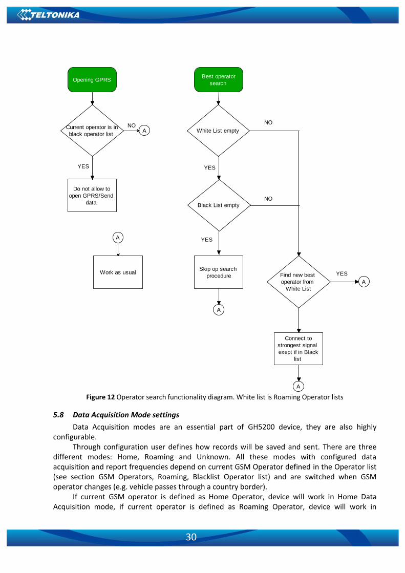
5.7 GSM Operators, Roaming, Blacklist Operator list
GH5200 can work in different modes (use different settings) according to the operator list defined. Operator list is used for Data Acquisition mode switching (see Data Acquisition Mode

29
settings section for more details). Modes are changed based on GSM operator GH5200 is connected to.
Figure 11 Roaming and Operator BlackList configuration
If roaming operator list is left empty, GH5200 will automatically detect home operator. If
home operator is written to the roaming operator list, it will still be detected as home operator. Any operator not in the roaming operator list (except the home operator) will be recognized as unknown operator and GH5200 will work in Unknown mode (make sure it is configured to allow data sending – GPRS context is enabled).
If user wants GH5200 to not connect and work with a particular operator it has to be written to Operator Blacklist. Up to 50 operators may be entered to this list.
Operator search procedure is initiated as normal every 15 minutes and tries to connect to an operator providing the strongest signal. It will prioritize operators which are specified in the operator list. If no operators from the operator list are available, the device will try to connect to an operator from the blacklist. If device connects to an operator from the blacklist, best operator search procedure is initiated instantly. During the time when device is connected to blacklisted operator no GPRS connection would be initiated and no data would be sent via GPRS. However, the ability to send SMS commands to the device would remain. If no suitable operator is found on both lists, the device will try to connect to a remaining available operator with the strongest signal.
30
Current operator is in
black operator list
Opening GPRS
Do not allow to
open GPRS/Send
data
A
Work as usual
A
YES
NOWhite List empty
Best operator
search
A
YES
NOBlack List empty
YES
Skip op search
procedure
NO
Find new best
operator from
White List
A
YES
Connect to
strongest signal
exept if in Black
list
A Figure 12 Operator search functionality diagram. White list is Roaming Operator lists
5.8 Data Acquisition Mode settings
Data Acquisition modes are an essential part of GH5200 device, they are also highly configurable.
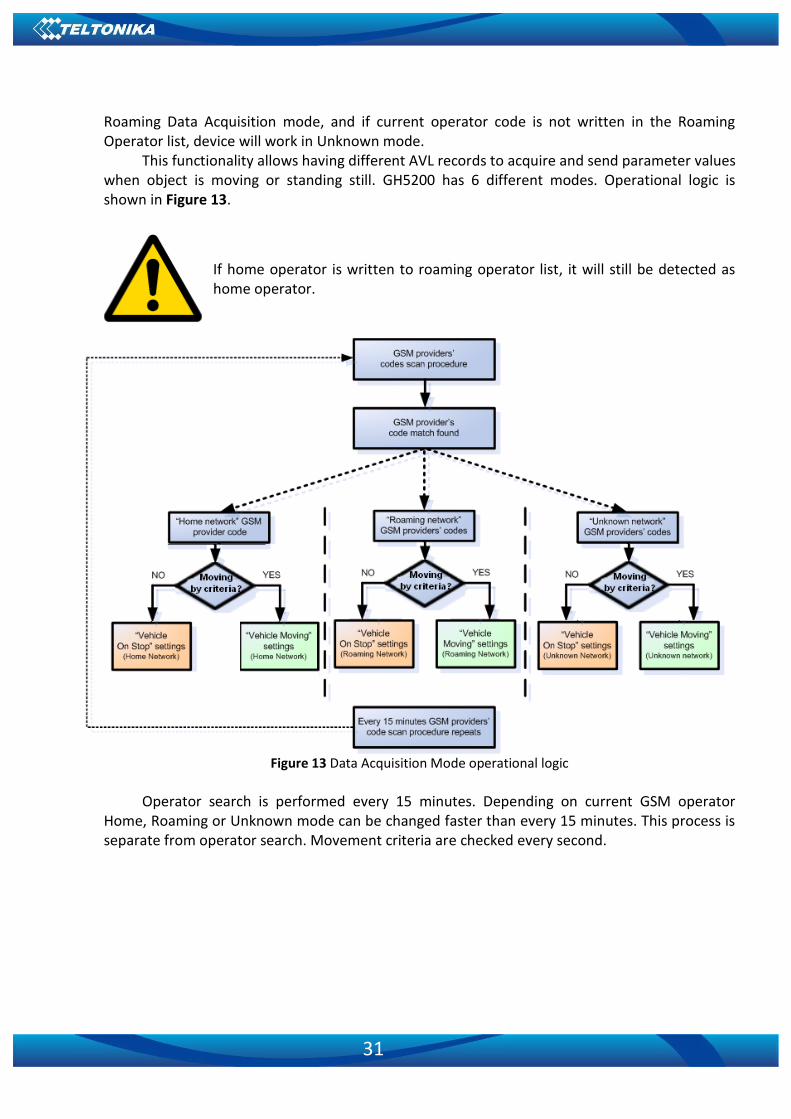
Through configuration user defines how records will be saved and sent. There are three different modes: Home, Roaming and Unknown. All these modes with configured data acquisition and report frequencies depend on current GSM Operator defined in the Operator list (see section GSM Operators, Roaming, Blacklist Operator list) and are switched when GSM operator changes (e.g. vehicle passes through a country border).
If current GSM operator is defined as Home Operator, device will work in Home Data Acquisition mode, if current operator is defined as Roaming Operator, device will work in
31
Roaming Data Acquisition mode, and if current operator code is not written in the Roaming Operator list, device will work in Unknown mode.
This functionality allows having different AVL records to acquire and send parameter values when object is moving or standing still. GH5200 has 6 different modes. Operational logic is shown in Figure 13.
Figure 13 Data Acquisition Mode operational logic
Operator search is performed every 15 minutes. Depending on current GSM operator
Home, Roaming or Unknown mode can be changed faster than every 15 minutes. This process is separate from operator search. Movement criteria are checked every second.
If home operator is written to roaming operator list, it will still be detected as home operator.
32
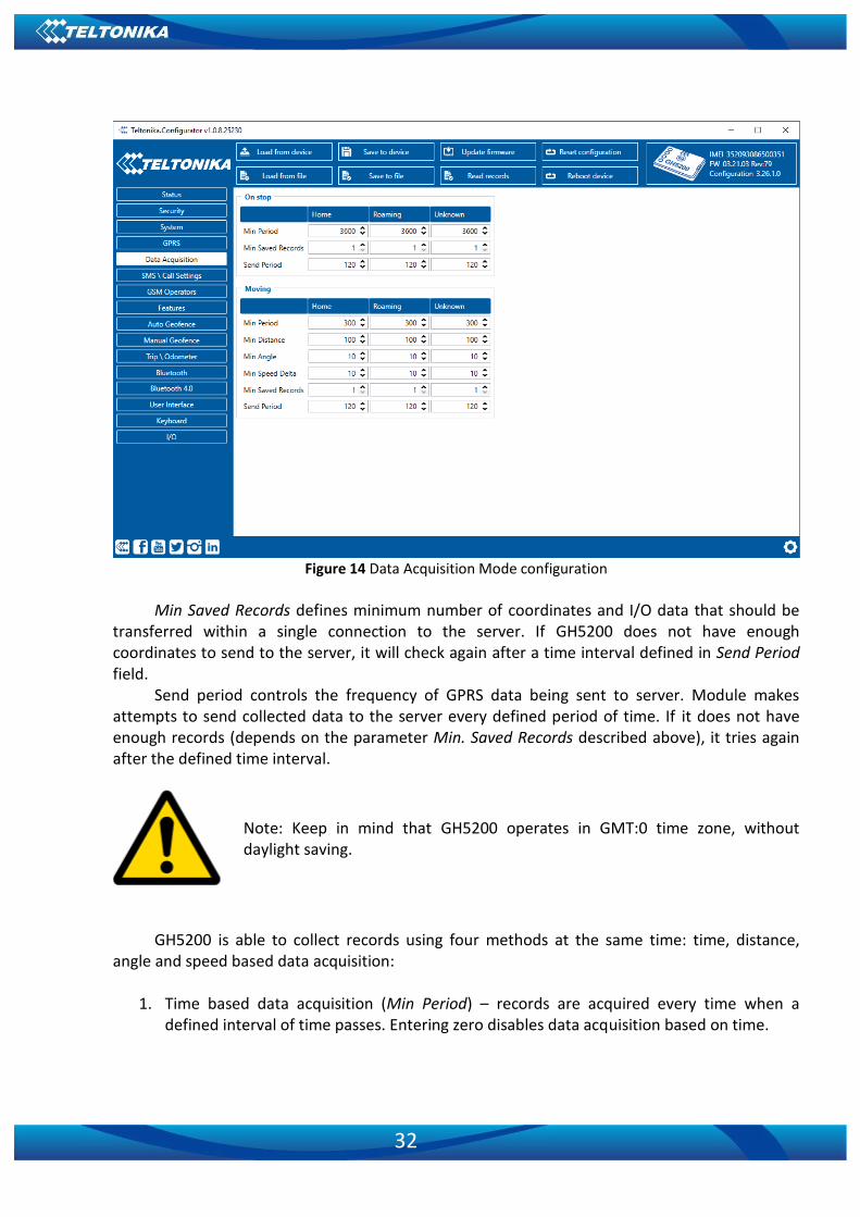
Figure 14 Data Acquisition Mode configuration
Min Saved Records defines minimum number of coordinates and I/O data that should be
transferred within a single connection to the server. If GH5200 does not have enough coordinates to send to the server, it will check again after a time interval defined in Send Period field.
Send period controls the frequency of GPRS data being sent to server. Module makes attempts to send collected data to the server every defined period of time. If it does not have enough records (depends on the parameter Min. Saved Records described above), it tries again after the defined time interval.
Note: Keep in mind that GH5200 operates in GMT:0 time zone, without daylight saving.
GH5200 is able to collect records using four methods at the same time: time, distance,
angle and speed based data acquisition:
1. Time based data acquisition (Min Period) – records are acquired every time when a defined interval of time passes. Entering zero disables data acquisition based on time.

33
Min. time period
2. Distance based data acquisition (Min Distance) – records are acquired when the distance
between previous coordinate and current position is greater than a defined parameter value. Entering zero disables data acquisition based on distance.
Min. distance
3. Angle based data acquisition (Min Angle) – records are acquired when the angle
difference between last recorded coordinate and current position is greater than a defined value. Entering zero disables data acquisition based on angle.
Min. angle
4. Speed based data acquisition (Min Speed Delta) – records are acquired when the speed
difference between last recorded coordinate and current position is greater than a defined value. Entering zero disables data acquisition based on speed.

34
5.9 Features settings
Three different scenarios can be selected in Features window.
Figure 15 Scenarios configuration
5.9.1 Alarm
This function can be only triggered by a button (Power Button or Alarm Button). When the alarm is triggered, an event with IO ID 236 is generated. Eventually an SMS will be sent and a call can be performed.
Figure 16 Alarm parameters

35
5.9.2 Over Speeding
This feature is used to prevent the driver from exceeding fixed speed and inspects the driver if needed. When vehicle speed exceeds maximum configured speed value the scenario is activated, and a record is generated. Scenario is activated until speed value decreases below the set parameter value.
Figure 17 Over Speeding parameters
5.9.3 ManDown
This feature gets current accelerometer data and calculates angles between offset positions. There are two positions: horizontal (when GPS antenna is in horizontal position facing the sky) and vertical. Scanning is performed each second. When calculated angle exceeds configured angle for configured time period, then an event is generated with configured priority and an SMS event takes place, if it is configured. When angle returns to allowed position, an event with the same priority is generated, an SMS can be sent and a call can be performed, if it is configured.
Figure 18 ManDown parameters

36
5.9.4 Movement Event
Movement Event functionality makes an eventual high priority record (and sends an optional SMS) when device is stationary or in motion (depending on configured "Mode") for set Timeout (added to "Movement Start/Stop Delays" accordingly).
Timeout is a configured amount of time (in seconds) after which an eventual high priority record is generated.
Note: this timeout is added with Movement Start Delay if configured Mode is Movement Event or with Movement Stop Delay if configured Mode is No Movement Event.
Movement Event mode generates a record after the start of movement whereas No Movement Event generates a record after the stop of movement.
Figure 19 Movement Event parameters
5.10 AutoGeofencing settings
AutoGeofence is based on the last known position after the movement has stopped. You
can be notified using this feature if the object has left the generated zone. The size of Geofence
zones are set by parameters. AutoGeofencing options can be configured by following parameters
as depicted in Figure 19 below.
AutoGeofence zone is generated immediately within set Radius value around tracker's
most recent position, when Auto Geofencing is enabled over Keyboard. Scenario can also be
activated through a SMS/GPRS command and can be disabled by SMS/GPRS, configured button
or a call. To disable Auto Geofencing scenario with a call, configure Incoming Call Settings to
Auto Geofence Off and set authorized numbers if such are used.
Note that AutoGeofencing does not require entering coordinates, instead it requires GPS
visibility.

37
Figure 20 Auto Geofence configuration
5.11 Manual Geofence
GH5200 has 50 configurable Geofence zones and it can generate an event when a defined
Geofence zone border is crossed. Frame border is an additional border around Geofence zone used to prevent false events when object stops on the border of the area and as a result records are made inside and outside the defined area because of GNSS errors. The event is generated only when both (Geofence and frame) borders are crossed. See Figure 20 for details: blue track is considered to have entered the area whereas red track is not.
Shape can be a rectangle or a circle as defined by the user.
Priority of Geofence event is categorized into Low, High or Panic levels. These levels define the priority of event information that is sent to the server. For more details about priorities look in I/O settings section.
Generate event allows to choose when record will be generated.
Figure 21 Geofence border

38
Eventual records controls where scenario status value appears: when disabled it will exist in each AVL record and when enabled the value will be appended only to eventual records.
OverSpeeding helps to configure OverSpeeding scenarios separately for each different Geozone. Regular OverSpeeding and geozones' OverSpeeding function independently. If digital output control is enabled in a regular OverSpeeding scenario, geozones OverSpeeding scenario will control it too i.e when the device is in more than one geozone and OverSpeeding is detected in any zone then the digital output turns on. Digital output turns off only when OverSpeeding is not detected anywhere.
X1 is used to set geofence zone left bottom corner X coordinate (longitude) whereas Y1 is
used to set Y coordinate (latitude). X2 or R are used to set accordingly geofence zone upper right corner X coordinate
(longitude) when Rectangular zone is used or circle radius when Circular zone is used. Y2 sets geofence zone upper right corner Y coordinate (latitude) for a Rectangular zone.
Figure 22 Geofence configuration

39
5.12 Bluetooth
5.12.1 General functionality
General functionality configures Bluetooth to work in slave mode. This mode allows any external device to connect to GH5200.
Parameter BT Radio allows enabling or disabling Bluetooth. There are three different settings: ▪ Disabled – Bluetooth functionality will be disabled. ▪ Enable (hidden) – Bluetooth functionality will be enabled, external devices will be able to
connect to GH5200, but no devices will be able to detect it. ▪ Enable (visible) – Bluetooth functionality will be enabled and any external device will be
able to detect and connect to GH5200. Local Name parameter lets user declare a
visible name of GH5200 to external devices. Local PIN parameter lets user configure
Bluetooth PIN of GH5200 device.
GH5200 Bluetooth has several different Security Modes: ▪ PIN only – only Local PIN will be reacquired to
complete connection to GH5200. ▪ PIN + MAC list – PIN and Authorized Devices
MAC List will be checked against to allow connection to GH5200. If the external device MAC ID is in the list and correct Local PIN is entered then connection will be established, otherwise GH5200 will reject connection.
▪ MAC list only – only Authorized Devices MAC List will be checked when trying to connect to GH5200. If external device MAC ID is in the list then connection will be established, otherwise GH5200 will reject connection.
▪ None – neither Local PIN nor Authorized Device MAC List will be checked.
Auto connection functionality configures GH5200 as master device, which allows connecting GH5200 to an external device. GH5200 currently supports these modes: ▪ None – disables auto connection
functionality. ▪ Hands Free – GH5200 starts searching for an
external hands free headset. If GH5200 finds a device which matches user defined External MAC or External Name then GH5200 will try to pair with that external device. If the
Figure 23 Bluetooth

40
external device asks for PIN then GH5200 will send user defined External PIN. After successfully pairing GH5200 will connect to paired device.
▪ Data Link – BT Data link mode is enabled by Configurator Data Link parameter: when Data Link is configured and GH5200 has a link with the server, paired device can send messages via Bluetooth SPP profile directly to the server. Messages will be encoded by codec12.
External Name parameter works as a substring, which allows user to enter a part of the full
external device name. For example, if external device name is "HandsFreeHeadset" and user enters "HandsFree" in External Name parameter window, then GH5200 will be allowed to connect to an external device named "HandsFreeHeadset".
5.12.2 How to connect Bluetooth Hands Free adapter to GH5200 device
5.12.2.1 Bluetooth settings configuration
These are instructions on how to easily create a connection between a Bluetooth Hands Free device and GH5200 device. First the GH5200 device Bluetooth settings need to be configured. These are the required steps: ▪ Connect GH5200 device to PC using USB cable. ▪ Launch GH5200 Configurator and connect to the device as shown in Figure 23.
Figure 24 GH5200 configurator devices connection window
▪ After successful connection to the device wait a few moments while the device loads the
current configuration, then nagivate to Bluetooth section as shown on Figure 24.
GH5200 supports ONE connection at a time. GH5200 can see up to 10 available devices. If there are more than 10 devices, the list may change with each new scan.

41
Figure 25 1 – Bluetooth settings; 2 – Enable Bluetooth; 3 – Bluetooth local name; 4 – Bluetooth security mode; 5 – Hands Free connection mode; 6 – External BT device name; 7 – Authorized Devices MAC list
▪ When device configuration is loaded press Bluetooth settings (Figure 24 position 1). ▪ Turn on BT Radio by pressing Enable (visible) (Figure 24 position 2). Local name (Figure 24
position 3) will be "GH5200_last 7 imei digits" by default, which can be changed. ▪ Set Security Mode (Figure 24 position 4) to PIN only or None. PIN + MAC list or MAC list
only security modes could also be selected, but in that case external device MAC address is required to be entered to Authorized Devices MAC List (Figure 24 7 position).
▪ Set connection mode to Hands Free (Figure 24 position 5). ▪ Set External Name (Figure 24 position 6) as your hands-free device name for proper
identification. In the given example hands-free headset name is "DMH10" but at least 2 characters are required to recognize it and connect to it. For better and quicker adapter identification on the network you could enter a full device name. You could check your hands-free adapter Bluetooth name by scanning nearby Bluetooth devices using a mobile phone or a computer with Bluetooth adapter.
▪ Go to SMS/Call Settings in main menu and set Incoming Call Action to Do Nothing as shown on Figure 25.
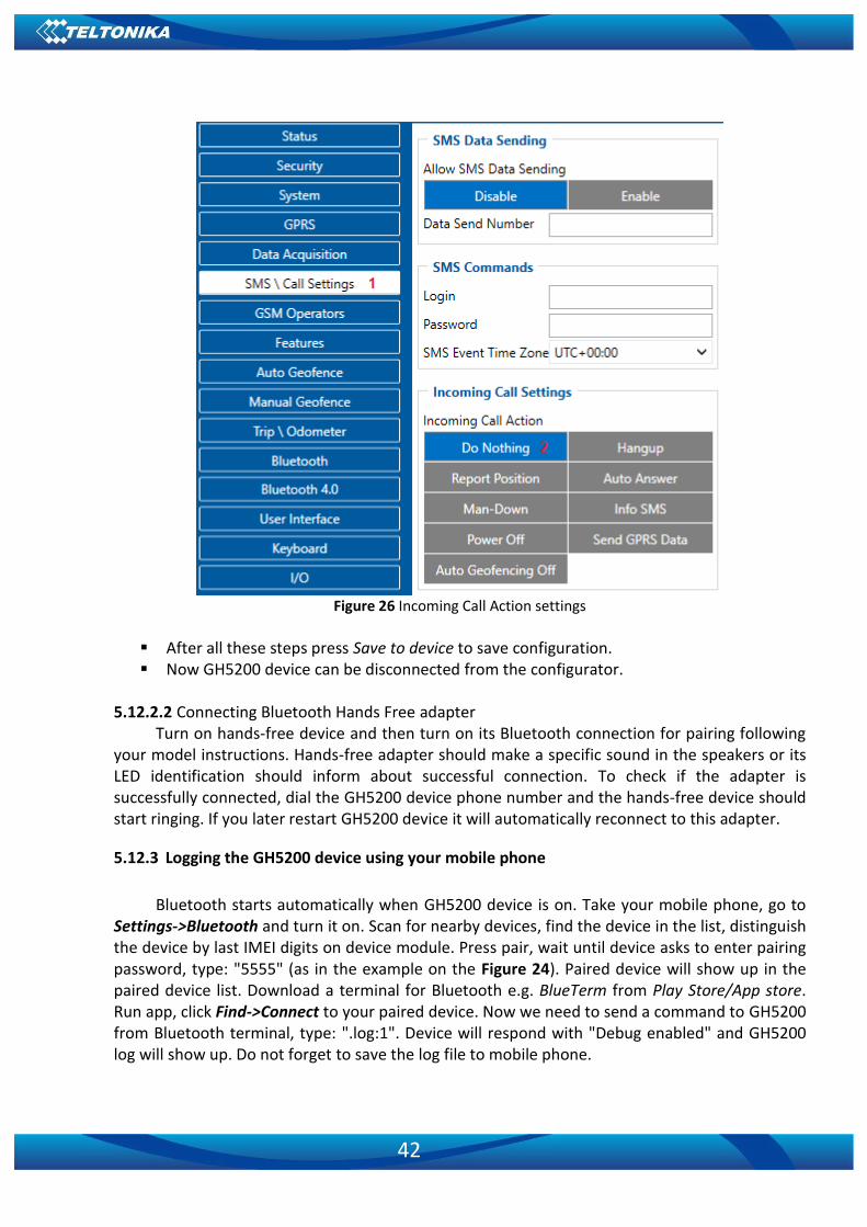
42
Figure 26 Incoming Call Action settings
▪ After all these steps press Save to device to save configuration. ▪ Now GH5200 device can be disconnected from the configurator.
5.12.2.2 Connecting Bluetooth Hands Free adapter
Turn on hands-free device and then turn on its Bluetooth connection for pairing following your model instructions. Hands-free adapter should make a specific sound in the speakers or its LED identification should inform about successful connection. To check if the adapter is successfully connected, dial the GH5200 device phone number and the hands-free device should start ringing. If you later restart GH5200 device it will automatically reconnect to this adapter.
5.12.3 Logging the GH5200 device using your mobile phone
Bluetooth starts automatically when GH5200 device is on. Take your mobile phone, go to
Settings->Bluetooth and turn it on. Scan for nearby devices, find the device in the list, distinguish the device by last IMEI digits on device module. Press pair, wait until device asks to enter pairing password, type: "5555" (as in the example on the Figure 24). Paired device will show up in the paired device list. Download a terminal for Bluetooth e.g. BlueTerm from Play Store/App store. Run app, click Find->Connect to your paired device. Now we need to send a command to GH5200 from Bluetooth terminal, type: ".log:1". Device will respond with "Debug enabled" and GH5200 log will show up. Do not forget to save the log file to mobile phone.

43
5.12.4 Device debug over Android smartphone
In order to pair FMB device with Android smartphone, make sure that BT radio is enabled
(visible) in device configuration. It can be checked via SMS command too: getparam 800
The answer has to be 2, which means Enabled (visible). ▪ Scan for visible BT devices using your Android
smartphone and connect to your GH5200 device. Default GH5200 BT name is: GH5200_last_7_imei_digits Default PIN code is: 5555

44
▪ Download Bluetooth Terminal application. Following link can be used:
https://play.google.com/store/apps/details?id=com.hatflabs.btt ▪ Run Bluetooth Terminal. In menu press Connect button
and select paired GH5200 device. To start log check CR and enter the command into terminal: .log:1
Wait ~10 minutes and press Save button in menu. You will find the saved log file in device
folder My Files/Bluetooth Terminal, select log files, press Share via Email and send them to Teltonika support.
Note: Unfortunately, it is not possible to perform debug the same way on iPhone, because there is no native SPP Bluetooth profile support on iPhone.

45
5.13 SMS events
SMS events functionality allows GH5200 to send a configured SMS when an event is triggered. This event can be triggered by every I/O element.
When any of the I/O elements is triggered, GH5200 sends a configured SMS message to a defined phone number. If SMS events are activated but there are no numbers defined in GSM Predefined Numbers list (similarly as in Figure 26), then the device will not send any messages.
Figure 27 GSM PreDefined Numbers list
The sent SMS messages format is following:
“Date Time Current Coordinate Event Text” For example, if GH5200 is configured to send an SMS, when Movement reaches high level
while configured with High priority and event generation on both range entrance and exit (as Figure 27), then the sent SMS is:
“2017/06/13 13:52:18 Lon:25.255537 Lat:54.667193 Movement 1”

46
Figure 28 Configured Movement SMS event
5.14 SMS Text
The SMS Text field can be altered and any text can be entered. Maximum message length is 160 symbols (numbers, letters and symbols in ASCII, except for comma symbol ",").
SMS Event Text may be either in default or composed format.
Default format:
Date, time, longitude, latitude, 'SMS text', value
Example:
2018/11/02 12:00:00 Lon:0.000000 Lat:0.000000 Alarm 1
Composed format:
Composed format may consist of text and defined commands which start with % symbol.
Supported commands:
Command Description
imei Device IMEI
fw Firmware version
fullfw Full Firmware version

47
Command Description
modem Modem Firmware version
gnss GPS Firmware version
lat Latitude (non-float value)
lon Longitude (non-float value)
sat Satellites in use
time Timestamp
pdp PDOP
hdp HDOP
mov Movement
op GSM Operator
spd Speed
sig GSM Signal
slp Sleep Mode
cel Cell ID
lac Area Code
datetime Time in hh:mm:ss format
val Eventual IO value
Io’par_id’ Element value by parameter ID
gmap Google Maps link
Composed text example:
%imei Movement %io50010
Event SMS text:
352094082828606 Movement 1
ATTENTION! If GH5200 is in Deep Sleep mode and an SMS event occurs with Low priority (which does not wake up GH5200), then the device does not send the message. It is saved to device memory until it wakes up from Deep Sleep mode and GSM modem starts working normally. After it wakes up, all the messages that are saved to memory will be sent, but keep in mind that only 10 messages can be saved to memory – all other messages will not be saved, until there is free memory space.
5.15 I/O settings
When no I/O element is enabled, AVL packet comes with GNSS information only. After enabling I/O element(s) AVL packet contains current value(s) of enabled I/O element(s) along with GNSS information.
If the device is connected to configurator all current I/O values are displayed in Current Value column.

48
Priority field allows enabling I/O elements and setting them a priority so they are added to the data packet, which is sent to the server. By default 8 I/O elements with low priority are enabled: Movement, Data Mode, GSM Signal, Sleep Mode, GNSS Status, GNSS PDOP, GNSS HDOP and Battery Voltage. Priority level (AVL packet priority) can be Low, High or Panic. All records made by GH5200 are regular, and regular packets are sent as low priority records. When Low priority event is triggered, GH5200 makes an additional record with an indication that the event was caused by an I/O element change (depending on Operand configuration). When High priority is selected, module makes an additional record with high priority flag and sends event packet immediately to the server using GPRS. Panic priority triggers same actions as High priority, but if GPRS fails, it sends an AVL packet using SMS data if SMS data sending is enabled and the number is provided in SMS/Call Settings.
High and Low levels define I/O value range. If I/O value enters or exits this range, GH5200 generates an event. Operand parameter defines when to generate event: On Exit, On Entrance, On Both, On Hysteresis or On Delta Change.
When Event Only is selected, I/O element status value will be appended only to eventual records, otherwise I/O element status value will appear in each AVL record.
5.15.1 Operand On Exit
Record is generated when input value leaves a range between low and high level limits.
Generate record
Current value < Low level
or
Current value > High level
Figure 29 On Exit operand logic
5.15.2 Operand On Entrance
Record is generated when input value enters a range between low and high level limits.
Generate record
Current value >= Low level
or
Current value <= High level
Figure 30 On Entrance operand logic
5.15.3 Operand On Both
Record is generated by both On Exit and On Entrance operands' logic at same time.

49
Generate record
Current value >= Low level
or
Current value <= High level
Current value < Low level
or
Current value > High level
Figure 31 On Both operand logic
5.15.4 Operand Monitoring
No event at all. Values are recorded only when other triggers worked.
Generate recordWait other events
Figure 32 Monitoring operand logic
5.15.5 Operand On Hysteresis
Record is generated when input value crosses the high limit value from below the low limit value or vice versa.
Figure 33 Hysteresis operand logic
5.15.6 Operand On Change
Record is generated when input value changes.

50
Generate recordCurrent value != last value
Figure 34 On change operand logic
5.15.7 Operand On Delta Change
Record is generated when input value changes and the absolute change becomes equal to or higher than the limit value.
Generate recordCurrent value != last value
|Last value - Current value|
>=
High level
Figure 35 On Delta Change operand logic
5.15.8 Avg const (Averaging parameter description)
If Avg Const value is 10, new value must be present for 1 second to register the change to a new value. Internal sampling is done every 40 ms, so 25 samples are taken per second. To configure 5 seconds of averaging multiply 10 by 5 yielding 50 as Avg Const value. The same logic works if the device is in Deep Sleep mode.
Averaging follows RC exponential curve, see image below:
Figure 36 Averaging counting explanation

51
For Boolean values 5τ, values is used, that means value change is taken when new values is averaged to more then 99.3%.
5.16 User Interface
Indication is configurable in User Interface tab of configurator or via Features ParametersID. Each 100 ms device checks if any indication is enabled in response
to triggered scenarios. If two scenarios need to indicate on the same indication source (LED or Vibration) then the active indicating scenario needs to be finished first (with exception of Alarm, Power Key Pressed and Device Off scenarios, which can override the control of indication sources). An example of indication configuration is given in the picture shown below. Period setting is indicative of Periodic scenarios (refer to the table below) and if Period is set to 0 the indication will take place immediately. When indication is periodic and On parameter value is set to 0, the indication source will stay on until the scenario is finished. Triggered scenarios will turn on LED and/or vibration for a configured On duration and then keep them off for a configured Off period of time. In case the configured Repeat value is higher than 0 the device continues a periodic on/off cycle.
Name Type Trigger Reason
GSM Error On event
SIM is not inserted, blocked, failed to connect to an operator or jammed
GSM Signal Established On event
Register to GSM network
SMS Send/Received On event
SMS is being received or sent
Incoming Call On event
Incoming call is in process
Call Active On event
Call is in process
Outgoing Call On event
Outgoing call is in process
Remote Connection On event
Device is connected to the server
Event On event
An event record is saved
Panic Event On event
A panic event record is saved
No GPS Fix Periodic Device tries to obtain valid GPS fix
GPS Fix Periodic Device has valid GPS fix
Device Off On event
Device is turning off
Device On On event
Device is turning on
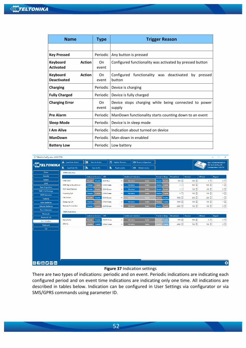
52
Name Type Trigger Reason
Key Pressed Periodic Any button is pressed
Keyboard Action Activated
On event
Configured functionality was activated by pressed button
Keyboard Action Deactivated
On event
Configured functionality was deactivated by pressed button
Charging Periodic Device is charging
Fully Charged Periodic Device is fully charged
Charging Error On event
Device stops charging while being connected to power supply
Pre Alarm Periodic ManDown functionality starts counting down to an event
Sleep Mode Periodic Device is in sleep mode
I Am Alive Periodic Indication about turned on device
ManDown Periodic Man-down in enabled
Battery Low Periodic Low battery
Figure 37 Indication settings
There are two types of indications: periodic and on event. Periodic indications are indicating each configured period and on event time indications are indicating only one time. All indications are described in tables below. Indication can be configured in User Settings via configurator or via SMS/GPRS commands using parameter ID.

53
Parameter ID Name Configuration values
Min Max Description
P+0 Enable 0 1 Enables or disables scenario
P+1 Enable In Sleep 0 1 0 – Disabled 1 – Enabled
P+2 LED 0 3
0 – Battery Red 1 – Battery Green 2 – GSM Red 3 – GSM Green 4 – GNSS Red 5 – GNSS Green 6 – None
P+3 Aditional Indication 0 3
0 – None 1 – Vibration 2 – Audio 3 – Vibration and Audio
P+4 Period 0 3600000 Period in milliseconds
P+5 On 0 10000 Time in ms
P+6 Off 0 10000 Time in ms
P+7 Repeat 0 100 Repeat count of On-Off Cycle
P – Parameter ID of indication scenario described. Indication works like this. Each 100 ms device checks if any indication is enabled and triggered. If indication is enabled and triggered then it starts. If other scenario has to be indicated on the same LED, vibration or audio, then it has to wait while active scenario finishes, only if indication has higher priority then indication with lower priority will be canceled. “Enable In Sleep” indications. This parameter allows to disable or enable indication, when device is in Deep Sleep, Online Deep Sleep or Ultra Deep Sleep modes. When “Low Power Mode” is configured, then “Enable In Sleep” parameter has no effect and indications are allowed if they is enabled. It is possible to configure indication’s LED, Vibration, Audio, Period, On, Off and Repeat. When period is set to 0, then indication will start immediately to indicate with configured resources. Indication will turn LED and Vibration on for configured ON timeout and play audio signal that is 100 ms long. After this timeout resources are turned off and indication waits for configured OFF timeout. When Off timeout exceeds, then device checks into Repeat configuration, if it is higher then 0, then indication repeats On/Off cycle for configured repeats, if it is 0, then indication is finished and indication will start on the next period, when indication is periodic. To set LED, vibration and audio to work permanently, indications ON timeout has to be set to 0. The resources will be freed only when scenario is canceled or higher priority indication starts executing. Permanent audio is using 100 ms long sound signal, then 100 ms pause. All configuration by parameter ID is in table above. When one of keyboard indications is triggered other indications will be suspended.

54
Indication scenarios, indication description and default settings:
Par ID Name Trigger Reason
Parameters default values
Enab
le
Enab
le In
Slee
p
Vib
ration
Au
dio
LED
14000 GSM Error When SIM not inserted, is blocked, failed to
connect to operator or jammed 1 0 0 0 GSM Red
14010 GSM signal established When device is registered to home or roaming network
0 0 0 0 GSM Green
14020 SMS Send/Received When SMS is received or sent 0 0 1 0 GSM Green
14030 Incoming Call When there is incoming call 0 0 1 0 GSM Green
14040 Remote Connection When device is connected to server 0 0 0 0 GSM Green
14050 Event When eventual record is saved 0 0 0 0 GNSS Green
14060 Panic Event When panic record is saved 0 0 0 0 GNSS Red
14070 No GPS Fix When device searches valid GPS fix 1 0 0 0 GNSS Green
14080 GPS Fix When device has valid GPS fix 1 0 0 0 GNSS Green
14090 Device Off When device is turning off 1 - 1 1 Battery Green
14100 Device ON When device turns on 1 - 1 1 Battery Green
14110 Key Pressed When device button is pressed 0 - 0 0 Battery Green
14130 Keyboard Action Activated Button was triggered with configured function to activate functionality
0 - 1 0 GNSS Green
14140 Keyboard Action Deactivated Button was triggered with configured function to deactivate functionality
0 - 1 0 GNSS Green
14150 Charging When device is charging 1 - 0 0 Battery Green
14160 Fully Charged When device is fully charged 1 - 0 0 Battery Green
14170 Pre Alarm When ManDown functionality starts counting timeout till event.
0 - 1 1 GNSS Red
14180 Sleep Mode When device is in sleep mode 0 1 0 0 GNSS Green
14190 I Am Alive When configured period passes 1 0 0 0 GNSS Green
14200 Battery Error
When charger connected and device is in critical temperature mode. Device enters this mode after termo shutdown, which is executed when temperature exceeds 65 ℃ temperature.
1 - 0 0 Battery Red
14210 Termo Shutdown When temperature exceeds 65 ℃ 1 - 1 0 Battery Red
14220 Low Battery When battery level is less of equal configured low battery level (12)
1 - 0 0 Battery Red
14230 Charger Error When somethings wrong happens while charging and charger is disabled forcefully
1 - 0 0 Battery Red
14240 Outgoing Call Not yet implemented 0 - 1 0 GNSS Green

55
Par ID Name Trigger Reason
Parameters default values
Enab
le
Enab
le In
Slee
p
Vib
ration
Au
dio
LED
14280 First Function When button is hold for configured timeout for detecting first function 1 - 0 1 Battery Green
14290 Second Function When button is hold for configured timeout for detecting second function
1 - 0 1 GSM Green
14300 Function Detective When button is hold for configured timeout for deactivation
1 - 0 1 GNSS Green
14310 Call Active When Voice call is in progress 1 1 0 0 GSM Green
14320 ManDown When ManDown event is generated 0 1 0 0 GSM Green
5.17 Keyboard
A virtual keyboard is based on five buttons: Alarm Button, 1, 2, 3 and Power Button. Each button has three click combinations and one Power Button-specific combination for power off: ▪ 1 Click – button is pressed once for no longer than two seconds. ▪ Clicks – button is pressed for no more than two times. Time between clicks has to be
shorter than one second. ▪ Long Click – button in pressed and held down for two seconds. ▪ 5 second-long click on Power Button - the device is turned off.
Figure 38 Keyboard settings
Name Trigger Reason

56
None Do nothing when button is triggered
Alarm Activate Alarm scenario
ManDown On Enable ManDown scenario
ManDown Off Disable ManDown scenario
ManDown Switch Activate/Deactivate ManDown scenario
Auto Geofence On Enable Auto Geofence scenario
Auto Geofence Off Disables Auto Geofence scenario
Auto Geofence Switch Activate/Deactivate Auto Geofence scenario
Call Initiates a call to the number selected in Call table
SMS Send an SMS to the number selected in SMS table
Tracking On Enable GNSS tracking
Tracking Off Disables GNSS tracking
Tracking Switch Enables/Disables GPS tracking
Movement Event On Enables movement scenario
Movement Event Off Disables movement scenario
Movement Event Switch Enables/Disables movement scenario
Answer Answer an incoming call in normal mode
Loud Answer Answer an incoming call in Loudspeaker mode
Hang-Up Hang-up incoming/outgoing call
Volume Up Increase active voice call volume
Volume Down Decrease active voice call volume
Switch Speaker Enable/Disable Loudspeaker mode
Power Off Turn off device
There is no restriction for configuring the same action for all button’s combinations.
6 SMS/GPRS COMMAND LIST2
All commands are case sensitive. When user tries to send SMS/GPRS message to GH5200 that operates in Deep Sleep mode, it cannot arrive to GH5200 device because the GSM/GPRS module is disabled most of the time. GH5200 will receive the SMS/GPRS message when it exits Deep Sleep mode. If GH5200 is in GPS Sleep or Online Deep Sleep mode, sent SMS/GPRS message will arrive to the device.
6.1 SMS/GPRS command list
Table 4. Common SMS/GPRS commands
2 GPRS commands require Codec 12 protocol

57
Command Description Response
getinfo Returns device runtime system information Yes
getver Returns code version, device IMEI, modem app version, RTC time, Init time, Uptime and BT MAC address
Yes
getstatus Returns modem status information Yes
getgps Returns current GPS data, date and time Yes
getio Reads out analog input, digital input and output Yes
ggps Returns location information with Google maps link Yes
readio # Returns IO status, # AVL ID Yes
cpureset Resets the device No
getparam # Returns selected parameter value, # param ID Yes
setparam #:# Sets selected parameter value 1.# - first ID value 2.# - New first Parameter Value 3.# - second ID value 4.# - New second Parameter Value 5.# - third ID value 6.# - New third Parameter Value SMS command is limited to 160 characters
Yes
setparam #:#;#:#;…
flush #,#,#,#,#,#,# Redirects device to other server 1.# - IMEI 2.# - APN 3.# - LOGIN 4.# - PASS 5.# - IP 6.# - PORT 7.# - MODE (0-TCP/1-UDP)
Yes
countrecs Returns records number Yes
deleterecords Deletes all records from SD card Yes
battery Returns battery state info Yes
wdlog Returns all information about watchdog restarts Yes
defaultcfg Loads default configuration Yes
setkey # # Adds a new configuration keyword or changes the current one. If device is locked, keyword cannot be changed 1.# - old keyword 2.# - new keyword
Yes
delkey # Removes existing keyword (If the device is locked, the keyword cannot be changed) # - old keyword
Yes
bbread # Returns black box information (HEX value of event ID and HEX value of custom data field (optional)). 1.# - returns entered number of latest events. When # is omitted the latest events are packed into a single
Yes
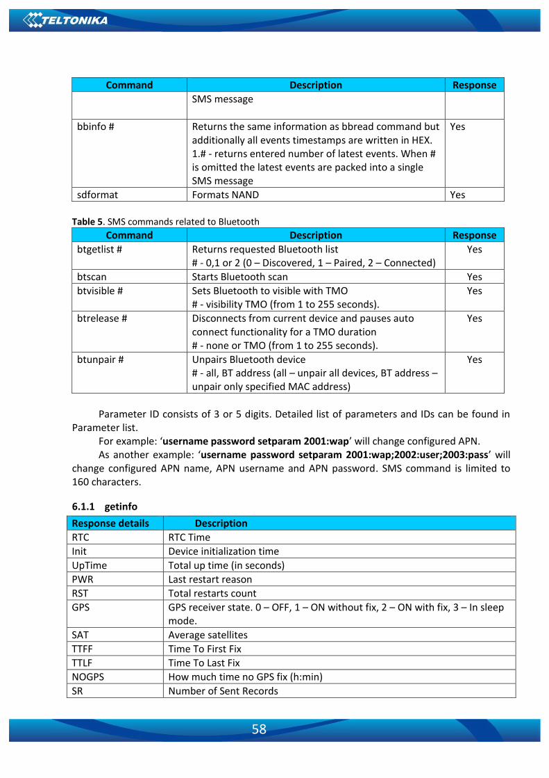
58
Command Description Response
SMS message
bbinfo # Returns the same information as bbread command but additionally all events timestamps are written in HEX. 1.# - returns entered number of latest events. When # is omitted the latest events are packed into a single SMS message
Yes
sdformat Formats NAND Yes
Table 5. SMS commands related to Bluetooth
Command Description Response
btgetlist # Returns requested Bluetooth list # - 0,1 or 2 (0 – Discovered, 1 – Paired, 2 – Connected)
Yes
btscan Starts Bluetooth scan Yes
btvisible # Sets Bluetooth to visible with TMO # - visibility TMO (from 1 to 255 seconds).
Yes
btrelease # Disconnects from current device and pauses auto connect functionality for a TMO duration # - none or TMO (from 1 to 255 seconds).
Yes
btunpair # Unpairs Bluetooth device # - all, BT address (all – unpair all devices, BT address – unpair only specified MAC address)
Yes
Parameter ID consists of 3 or 5 digits. Detailed list of parameters and IDs can be found in
Parameter list. For example: ‘username password setparam 2001:wap’ will change configured APN. As another example: ‘username password setparam 2001:wap;2002:user;2003:pass’ will
change configured APN name, APN username and APN password. SMS command is limited to 160 characters.
6.1.1 getinfo
Response details Description
RTC RTC Time
Init Device initialization time
UpTime Total up time (in seconds)
PWR Last restart reason
RST Total restarts count
GPS GPS receiver state. 0 – OFF, 1 – ON without fix, 2 – ON with fix, 3 – In sleep mode.
SAT Average satellites
TTFF Time To First Fix
TTLF Time To Last Fix
NOGPS How much time no GPS fix (h:min)
SR Number of Sent Records

59
Response details Description
FG Failed GPRS counter
FL Failed link counter
SMS Sent SMS Counter
REC Records Found – number of records stored in the memory
MD Data Mode state. 0 – Home and Stop, 1 – Home and Moving, 2 – Roaming and Stop, 3 – Roaming and Moving, 4 – Unknown and Stop, 5 – Unknown and Moving
Example: “RTC:2017/6/16 7:13 Init:2017/6/16 5:44 UpTime:4744s PWR:PwrVoltage RST:0 GPS:1 SAT:0 TTFF:0 TTLF:0 NOGPS: 1:18 SR:0 FG:200 FL:0 SMS:3 REC:42 MD:1”.
6.1.2 getver
Response details Description
Ver Firmware version
GPS Version of GPS module
Hw Version of hardware
Mod HW version modification
IMEI Device IMEI
Init Device initialization time
Uptime Total up time (in seconds)
BT Device MAC address
Example: “Ver:02.00.01_06 GPS:AXN_3.80_3333_16070400,0000,, Hw:GH5200 Mod:4 IMEI:352094082042885 Init: 2017-6-16 5:54 Uptime: 16574 BT:31F5BFE66261”.
6.1.3 getstatus
Response details Description
Data Link Indicates module connection to server at the moment: 0 – Not connected, 1 – Connected
GPRS Indicates if GPRS is available at the moment
Phone Voice Call status: 0 – Ready, 1 – Unavailable, 2 – Unknown, 3 – Ringing, 4 – Call in progress, 5 – Asleep
SIM SIM Status: 0 – Ready, 1 – PIN, 2 – PUK, 3 – PIN2, 4 – PUK2
OP When connected to GSM Operator: numerical ID of operator
Signal GSM Signal Quality [0-5]
NewSMS Indicates if new message has been received
Roaming 0 – Home Network, 1 – Roaming
SMSFull Indicates whether SMS storage is full. 0 – OK, 1 – SMS storage is full
LAC GSM Tower Location Area Code
Cell ID GSM Tower Cell ID Code
Example: “Data Link: 0 GPRS: 1 Phone: 0 SIM: 0 OP: 24602 Signal: 5 NewSMS: 0 Roaming: 0 SMSFull: 0 LAC: 1 Cell ID: 3055”.
6.1.4 getgps
Response details Description

60
Response details Description
GPS Indicates valid (1) or invalid (0) Gps data
Sat Provides currently available satellites’count
Lat Latitude (Last good Latitude)
Long Longitude (Last good Longitude)
Alt Altitude
Speed Ground speed, km/h
Dir Ground direction, degrees
Date Current date
Time Current GMT time
Example: “GPS:1 Sat:0 Lat:54.666042 Long:25.225031 Alt:0 Speed:0 Dir:0 Date: 2017/6/16 Time: 12:52:30”.
6.1.5 ggps
Response details Description
D Date
T Time
S Actual Speed
C Latitude (Last good Latitude), Longitude (Last good Longitude)
Url Google Maps Link
Example (if no GNSS FIX): “GPS Data not Available. No GPS signal”. Example: D:17/1/9 T:12:52:30 S:0.00 C:54.666042, 25.225032 Url:
http://maps.google.com/?q=54.666042,25.225032&om=1speed:0
6.1.6 getparam
Reads parameter value for given ID that consists of 3 or 5 digits. A detailed list of parameters and identifiers can be found in the following chapter.
For example: getparam 2001 command will request APN name. Example answer: Param ID:2001 Value:wap
6.1.7 setparam
Reads parameter value for a given ID that consists of 3 or 5 digits. A detailed list of parameters and identifiers can be found in the following chapter.
For example: setparam 2001:wap will change configured APN name. Answer: Param ID:2001 Value:wap2 Another example: setparam 2001:wap;2002:user;2003:pass will change configured APN
name, APN username and APN password. SMS command of limited to 160 characters.
6.1.8 flush #,#,#,#,#,#,#
Initiates all data transfer by GPRS to a specified target server. Comma separated parameters go in following order:
1.# - IMEI 2.# - APN 3.# - GPRS LOGIN 4.# - GPRS PASSWORD

61
5.# - IP 6.# - PORT 7.# - MODE (0 – TCP/1 – UDP) Parameters are separated by comma (no spaces needed). In case you do not need to enter
parameter (APN Login/ APN Pass) – do not use space, simply enter comma and write next parameter.
Example: opa opa flush 353976012555151,banga,,,212.47.99.62,12050,0
Response details Description
FLUSH SMS Accepted FLUSH SMS Accepted
# records found on FLASH Number of records found on FLASH
Minimum Records to Send: # Number of minimum saved records to send
GPRS Enabled: # State of the GPRS connection: 0 – Disabled; 1 – Enabled
Time Sync: # Indicates time synchronization on the device: 0 – Not synchronized; 1 – Synchronized
Example: “FLUSH SMS Accepted. 11 records found on FLASH. Minimum Records to Send: 1. GPRS Enabled: 1. Time Sync: 1.”
6.1.9 countrecs
Returns current number of records stored in the device memory. Example (if more than 100): “more than 100 records found” Example: “25 records found”
6.1.10 deleterecords
Deletes all records from the device memory.
6.1.11 battery
Response details Description
BatState Battery connected (1) or disconnected (0) from device
FSMState Current battery state
ChargerIC Battery charging status
ExtV External Voltage
BatV Battery voltage
BatI Battery charging current
Example: “BatState: 1 FSMState: ACTIVE ChargerIC: OFF ExtV: 11796 BatV: 3942 BatI: 0”
6.1.12 btgetlist #
btgetlist command needs argument what list should be printed! btgetlist 0; device will respond with BT_LIST_Discovered. btgetlist 1; device will respond with all paired devices. btgetlist 2; device will respond with connected blutetooth device.

62
6.1.13 setkey # #
"setkey <oldkeyword> <newkeyword>" - Set new or change the keyword. Configuration should be not locked.
Example: New keyword (set) <name>{space}<pass>{space}setkey{space}{space}<newkeyword>
Another example: Change keyword (change) <name>{space}<pass>{space}setkey{space}<oldkeyword>{space}<newkeyword>
6.1.14 delkey # #
"delkey <keyword>" - Deletes current keyword. Configuration keyword should be configured and not locked.
Example: <name>{space}<pass>{space}delkey{space}<keyword>
6.1.15 bbread #
# describes start offset and is an optional field. For example, value of 20 means that blackbox data is requested starting from 20th latest event. When # is omitted the most recent events are packet into a single SMS.
Example: X1:Y1,X2:Y2,…,Xn:Yn, where Xn – HEX value of event ID. Yn – HEX value of custom data field (optional).
6.1.16 bbinfo #
# describes start offset and is an optional field. For example, value of 20 means that blackbox data is requested starting from 20th latest event. When # is omitted the most recent events are packet into a single SMS.
Example: X1-Y1:Z1,X2-Y2:Z2,…,Xn-Yn:Zn, where Xn – timestamp in HEX. Yn – HEX value of event ID. Zn – HEX value of custom data field (optional).
6.1.17 sdformat
Format device memory (deletes all information from device memory).
Note: Without argument it is always 0 i.e BT_LIST_Discovered. In FW 01.00.23 btgetlist (without args) will not respond (as unknown command).

63
7 PARAMETER LIST
7.1 System parameters
7.1.1 Sleep Mode (ID=102)
Device has three sleep modes: GPS sleep, Deep Sleep and Online Deep Sleep mode. When sleep is disabled (value 0) module will never enter sleep mode, in sleep mode (value 1) module reduces level of power usage by turning GPS module to sleep, in deep sleep mode (value 2) module turns GPS module to sleep and device is deregistered from network (note, that GH5200 do not receive SMS when in deep sleep), online Deep Sleep mode (value 3) device works as in Deep Sleep mode, but without deregistering from GSM network. GSM part stays powered, so this increases power consumption. In this mode, device should received/send SMS and make/receive calls. Also not closes GPRS context, if previously opened.
Minimum value
Maximum value
Default value Goes with (depends on) parameters
Value type
0 4 2 Sleep timeout (ID=103) Uint8
7.1.2 Sleep timeout (ID=103)
Sleep timeout is time after which GH5200 goes into GPS sleep, Deep Sleep or Online Deep Sleep if other requirements are met. Its parameter is set in minutes.
Minimum value
Maximum value
Default value Goes with (depends on) parameters
Value type
1 3000 10 Sleep Mode (ID=102) Uint8
7.1.3 Static Navigation (ID=106)
When static navigation is enabled, GH5200 filters out GPS jumps, when it is not moving. When it is disabled, it does not make any changes to collected GPS data.
Minimum value
Maximum value
Default value Goes with (depends on) parameters
Value type
0 1 1 Uint8
7.1.4 Saving/Sending without time synchronization (ID=107)
When this feature is enabled (value = 1), then records can be saved and sent to server without time synchronization.
Minimum value
Maximum value
Default value Goes with (depends on) parameters
Value type
0 2 0 Uint8
7.1.5 GNSS Source (ID=109)
This parameter sets satellite system(s), available values are:
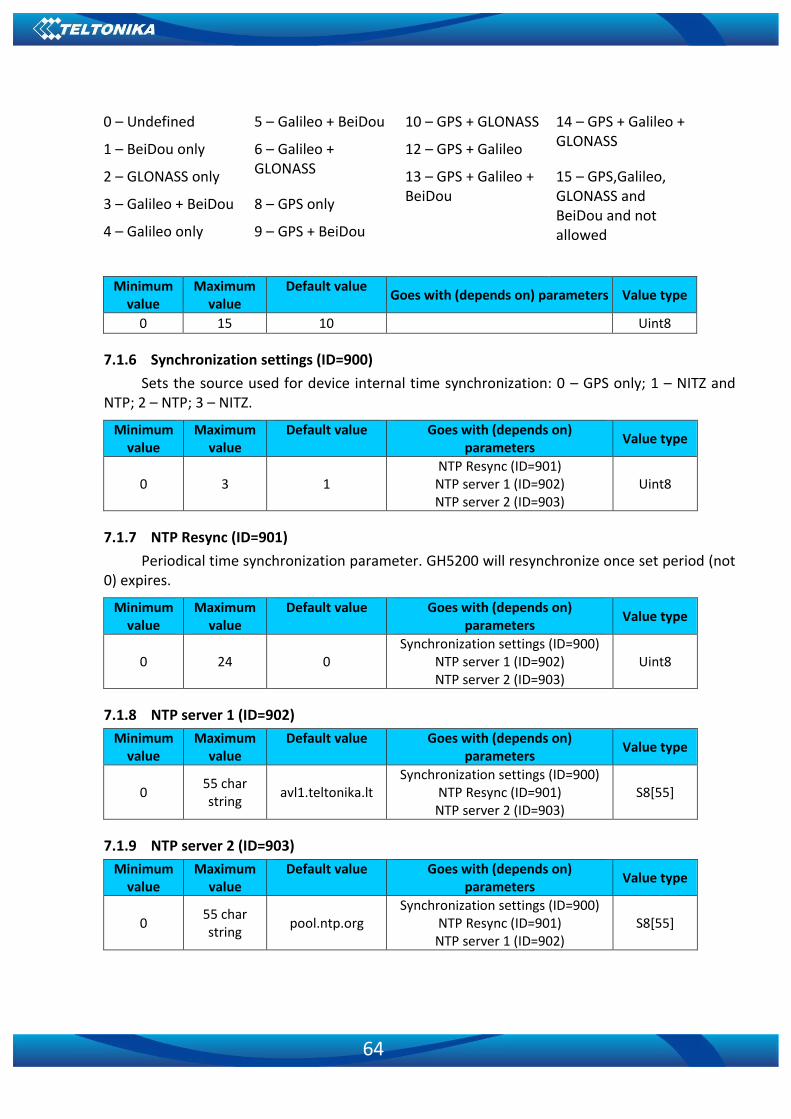
64
0 – Undefined 5 – Galileo + BeiDou 10 – GPS + GLONASS 14 – GPS + Galileo + GLONASS 1 – BeiDou only 6 – Galileo +
GLONASS 12 – GPS + Galileo
2 – GLONASS only 13 – GPS + Galileo + BeiDou
15 – GPS,Galileo, GLONASS and BeiDou and not allowed
3 – Galileo + BeiDou 8 – GPS only
4 – Galileo only 9 – GPS + BeiDou
Minimum value
Maximum value
Default value Goes with (depends on) parameters Value type
0 15 10 Uint8
7.1.6 Synchronization settings (ID=900)
Sets the source used for device internal time synchronization: 0 – GPS only; 1 – NITZ and NTP; 2 – NTP; 3 – NITZ.
Minimum value
Maximum value
Default value Goes with (depends on) parameters
Value type
0 3 1 NTP Resync (ID=901) NTP server 1 (ID=902) NTP server 2 (ID=903)
Uint8
7.1.7 NTP Resync (ID=901)
Periodical time synchronization parameter. GH5200 will resynchronize once set period (not 0) expires.
Minimum value
Maximum value
Default value Goes with (depends on) parameters
Value type
0 24 0 Synchronization settings (ID=900)
NTP server 1 (ID=902) NTP server 2 (ID=903)
Uint8
7.1.8 NTP server 1 (ID=902)
Minimum value
Maximum value
Default value Goes with (depends on) parameters
Value type
0 55 char string
avl1.teltonika.lt Synchronization settings (ID=900)
NTP Resync (ID=901) NTP server 2 (ID=903)
S8[55]
7.1.9 NTP server 2 (ID=903)
Minimum value
Maximum value
Default value Goes with (depends on) parameters
Value type
0 55 char string
pool.ntp.org Synchronization settings (ID=900)
NTP Resync (ID=901) NTP server 1 (ID=902)
S8[55]

65
7.2 GPRS parameters
7.2.1 Sorting (ID=1002)
Record sorting parameter is responsible for record sorting order. Value of 0 results in arranging data starting from newest record, another option is to sort by oldest record.
Minimum value
Maximum value
Default value Goes with (depends on) parameters
Value type
0 1 0 Open Link Timeout (ID=1000)
Server Response Timeout (ID=1001)
Uint8
7.2.2 Open Link Timeout (ID=1000)
Defines how many seconds device will keep connection to the server after successful data transfer while waiting for a new record.
Minimum value
Maximum value
Default value Goes with (depends on) parameters
Value type
30 259200 30 Sorting (ID=1002)
Server Response Timeout (ID=1001)
Uint32
7.2.3 Server Response Timeout (ID=1001)
Defines time period in seconds for server response to sent records.
Minimum value
Maximum value
Default value Goes with (depends on) parameters
Value type
5 300 30 Sorting (ID=1002)
Open Link Timeout (ID=1000) Uint16
ATTENTION! Some GSM operators may disconnect the device from an active data link if the device does not send any data for a very long duration, even if the active data link timeout is set to maximum value. The amount of time that an operator keeps the link open depends solely on the operator. For example, if active data link timeout is set to maximum of 259200 seconds (72 hours) and the device sends data to server every 86400 seconds (24 hours), the operator might disconnect the link earlier and the device will have to connect to the server again. This may cost extra, depending on the operator GPRS data charges. When using active data link timeout, it is strongly recommended that data sending to the server is not rare (24 hours or less).
7.2.4 SIM GPRS content activation (ID=2000)
Parameter allows or does not allow GPRS usage with SIM, value of 0 disallows GPRS.
Minimum value
Maximum value
Default value Goes with (depends on) parameters
Value type
0 1 1 SIM APN Name (ID=2001)
SIM SIM APN Username (ID=2002) SIM SIM APN Password (ID=2003)
Uint8

66
7.2.5 SIM APN Name (ID=2001)
Parameter defines SIM GPRS Access Point Name.
Minimum value
Maximum value
Default value Goes with (depends on) parameters
Value type
0 32 char string
Empty
SIM SIM GPRS content activation (ID=2000)
SIM SIM APN Username (ID=2002) SIM SIM APN Password (ID=2003)
S8[32]
7.2.6 SIM APN Username (ID=2002)
Parameter defines SIM APN username. In case operator does not use username for login, value should be empty.
Minimum value
Maximum value
Default value Goes with (depends on) parameters
Value type
0 30 char string
Empty
SIM GPRS content activation (ID=2000)
SIM APN Name (ID=2001) SIM APN Password (ID=2003)
S8[30]
7.2.7 SIM APN Password (ID=2003)
Parameter defines SIM APN password. In case operator does not use password for login, value should be empty.
Minimum value
Maximum value
Default value Goes with (depends on) parameters
Value type
0 30 char string
Empty
SIM GPRS content activation (ID=2000)
SIM APN Name (ID=2001) SIM APN Username (ID=2002)
S8[30]
7.2.8 Domain (ID=2004)
Parameter defines data destination server IP address. Example: 212.47.99.62
Minimum value
Maximum value
Default value Goes with (depends on) parameters
Value type
0 55 char string
Empty SIM GPRS content activation
(ID=2000) S8[55]
7.2.9 Target Server Port (ID=2005)
Parameter defines data destination server port number. Example: 12050
Minimum value
Maximum value
Default value Goes with (depends on) parameters
Value type
0 65535 0 SIM GPRS content activation
(ID=2000) Uint16

67
7.2.10 Protocol (ID=2006)
Parameter defines GPRS data transport protocol. Module can use TCP or UDP transport protocol to send data to the server. For TCP protocol use value of 0, for UDP protocol value is 1.
Minimum value
Maximum value
Default value Goes with (depends on) parameters
Value type
0 1 0 SIM GPRS content activation
(ID=2000) Uint8
7.2.11 Backup Server Domain (ID=2007)
This parameter defines data destination backup server IP address. Example: 212.47.99.61
Minimum value
Maximum value
Default value Goes with (depends on) parameters
Value type
0 55 char string
Empty SIM GPRS content activation
(ID=2000) Backup Server Mode (ID=2010)
S8[55]
7.2.12 Backup Server Port (ID=2008)
Parameter defines data destination backup server port number. Example: 12051
Minimum value
Maximum value
Default value Goes with (depends on) parameters
Value type
0 65535 0 SIM GPRS content activation
(ID=2000) Backup Server Mode (ID=2010)
Uint16
7.2.13 Backup Server Protocol (ID=2009)
Parameter defines GPRS data transport protocol. Module can use TCP or UDP transport protocol to send data to backup server. For TCP protocol use 0, for UDP protocol value is 1.
Minimum value
Maximum value
Default value Goes with (depends on) parameters
Value type
0 1 0 SIM GPRS content activation
(ID=2000) Backup Server Mode (ID=2010)
Uint8
7.2.14 Backup Server Mode (ID=2010)
Sets backup server mode: 0 – Disable (backup server not used); 1 – Backup (sent to backup server if main server not available); 2 – Duplicate (send records to both servers).
Minimum value
Maximum value
Default value Goes with (depends on) parameters
Value type
0 2 0 SIM GPRS content activation
(ID=2000) Uint8
7.2.15 FOTA WEB status (ID=13003)
This parameter allows or disallows connection to FOTA WEB server.

68
Minimum value
Maximum value
Default value Goes with (depends on)
parameters Value type
0 1 1 FOTA WEB Domain (ID=13000)
FOTA WEB port (ID=13001) FOTA WEB Period (min) (ID=13002)
Uint8
7.2.16 FOTA WEB Domain (ID=13000)
FOTA WEB server IP or DNS address.
Minimum value
Maximum value
Default value Goes with (depends on)
parameters Value type
0 55 char string
85.206.140.106 FOTA WEB status (ID=13003) FOTA WEB port (ID=13001)
FOTA WEB Period (min) (ID=13002) S8[55]
7.2.17 FOTA WEB port (ID=13001)
FOTA WEB server port.
Minimum value
Maximum value
Default value Goes with (depends on)
parameters Value type
0 65535 5000 FOTA WEB status (ID=13003)
FOTA WEB Domain (ID=13000) FOTA WEB Period (min) (ID=13002)
Uint16
7.2.18 FOTA WEB Period (min) (ID=13002)
This parameter defines how often device connects to the server.
Minimum value
Maximum value
Default value Goes with (depends on)
parameters Value type
30 65535 720 FOTA WEB status (ID=13003)
FOTA WEB Domain (ID=13000) FOTA WEB port (ID=13001)
Uint16
7.3 SMS/Call settings
7.3.1 SMS data sending settings (ID=3000)
Parameter controls sending AVL data using binary SMS. It is equal to 1 when it is allowed.
Minimum value
Maximum value
Default value Goes with (depends on) parameters
Value type
0 1 0 Data send number (ID=3001) Uint8
7.3.2 Data send number (ID=3001)
This parameter defines a GSM number which is ready to receive Data SMS.
Minimum value
Maximum value
Default value Goes with (depends on) parameters
Value type
Empty 16 digits - SMS data sending settings
(ID=3000) S8[16]
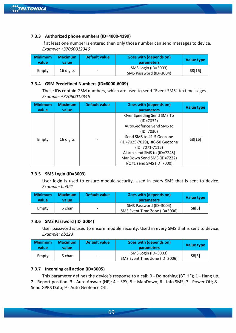
69
7.3.3 Authorized phone numbers (ID=4000-4199)
If at least one number is entered then only those number can send messages to device. Example: +37060012346
Minimum value
Maximum value
Default value Goes with (depends on) parameters
Value type
Empty 16 digits - SMS Login (ID=3003)
SMS Password (ID=3004) S8[16]
7.3.4 GSM Predefined Numbers (ID=6000-6009)
These IDs contain GSM numbers, which are used to send “Event SMS” text messages. Example: +37060012346
Minimum value
Maximum value
Default value Goes with (depends on) parameters
Value type
Empty 16 digits -
Over Speeding Send SMS To (ID=7032)
AutoGeofence Send SMS to (ID=7030)
Send SMS to #1-5 Geozone (ID=7025-7029), #6-50 Geozone
(ID=7071-7115) Alarm send SMS to (ID=7245)
ManDown Send SMS (ID=7222) I/O#1 send SMS (ID=7000)
S8[16]
7.3.5 SMS Login (ID=3003)
User login is used to ensure module security. Used in every SMS that is sent to device. Example: ba321
Minimum value
Maximum value
Default value Goes with (depends on) parameters
Value type
Empty 5 char - SMS Password (ID=3004)
SMS Event Time Zone (ID=3006) S8[5]
7.3.6 SMS Password (ID=3004)
User password is used to ensure module security. Used in every SMS that is sent to device. Example: ab123
Minimum value
Maximum value
Default value Goes with (depends on) parameters
Value type
Empty 5 char - SMS Login (ID=3003)
SMS Event Time Zone (ID=3006) S8[5]
7.3.7 Incoming call action (ID=3005)
This parameter defines the device’s response to a call: 0 - Do nothing (BT HF); 1 - Hang up; 2 - Report position; 3 - Auto Answer (HF); 4 – SPY; 5 – ManDown; 6 - Info SMS; 7 - Power Off; 8 - Send GPRS Data; 9 - Auto Geofence Off.

70
Minimum value
Maximum value
Default value Goes with (depends on) parameters
Value type
0 9 0 Uint8
7.3.8 SMS Event Time Zone (ID=3006)
Time zone which will be used in event SMS messages.
Minimum value
Maximum value
Default value
Goes with (depends on) parameters
Value type
-720 840 0 SMS Password (ID=3004)
SMS Login (ID=3003) Uint16
7.3.9 Detect Number Type By Plus Symbol (ID=4999)
When enabled, numbers with “+” symbols will be used as international and numbers without it - as local/unknown. 0 – Disable; 1 – Enable.
Minimum value
Maximum value
Default value Goes with (depends on) parameters
Value type
0 10 0
Authorized Numbers (ID=4000-4199)
GSM Predefined Numbers (ID=6000-6009)
Uint8
7.4 GSM Operators
7.4.1 SIM Roaming Operator List (ID=5000-5049)
This parameter list defines a roaming operator list for SIM. An operating profile is selected ccording to this list. If roaming operator list is left empty, GH5200 will automatically detect a home operator. If home operator is written to any part of the roaming operator list, it will still be detected as a home operator. All other written operators are Preferred Roaming Operator Codes. More information about operator search functionality can be found in GSM Operators Roaming and Blacklist Operator list.
Minimum value
Maximum value
Default value Goes with (depends on) parameters
Value type
0 999999 0 Black List (ID=5500-5549) Uint32
7.4.2 Black List (ID=5500-5549)
If it is required that GH5200 does not connect to a particular operator it must be written to the Operator BlackList. Refer to GSM Operators Roaming and Blacklist Operator list for more information.
Minimum value
Maximum value
Default value Goes with (depends on) parameters
Value type
0 999999 0 Roaming Operator List (ID=5000-
5049) Uint32
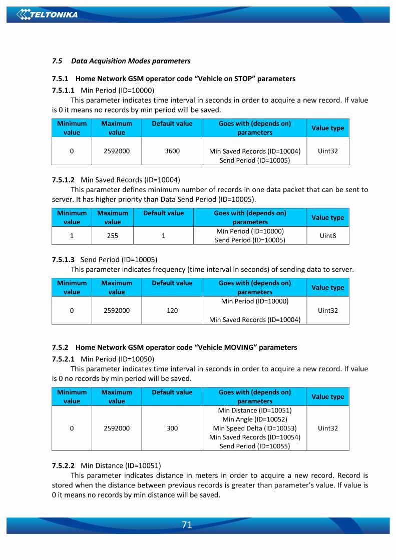
71
7.5 Data Acquisition Modes parameters
7.5.1 Home Network GSM operator code “Vehicle on STOP” parameters
7.5.1.1 Min Period (ID=10000) This parameter indicates time interval in seconds in order to acquire a new record. If value
is 0 it means no records by min period will be saved.
Minimum value
Maximum value
Default value Goes with (depends on) parameters
Value type
0 2592000 3600
Min Saved Records (ID=10004) Send Period (ID=10005)
Uint32
7.5.1.2 Min Saved Records (ID=10004)
This parameter defines minimum number of records in one data packet that can be sent to server. It has higher priority than Data Send Period (ID=10005).
Minimum value
Maximum value
Default value Goes with (depends on) parameters
Value type
1 255 1 Min Period (ID=10000) Send Period (ID=10005)
Uint8
7.5.1.3 Send Period (ID=10005)
This parameter indicates frequency (time interval in seconds) of sending data to server.
Minimum value
Maximum value
Default value Goes with (depends on) parameters
Value type
0 2592000 120
Min Period (ID=10000)
Min Saved Records (ID=10004) Uint32
7.5.2 Home Network GSM operator code “Vehicle MOVING” parameters
7.5.2.1 Min Period (ID=10050) This parameter indicates time interval in seconds in order to acquire a new record. If value
is 0 no records by min period will be saved.
Minimum value
Maximum value
Default value Goes with (depends on) parameters
Value type
0 2592000 300
Min Distance (ID=10051) Min Angle (ID=10052)
Min Speed Delta (ID=10053) Min Saved Records (ID=10054)
Send Period (ID=10055)
Uint32
7.5.2.2 Min Distance (ID=10051)
This parameter indicates distance in meters in order to acquire a new record. Record is stored when the distance between previous records is greater than parameter’s value. If value is 0 it means no records by min distance will be saved.

72
Minimum value
Maximum value
Default value Goes with (depends on) parameters
Value type
0 65535 100
Min Period (ID=10050) Min Angle (ID=10052)
Min Speed Delta (ID=10053) Min Saved Records (ID=10054)
Send Period (ID=10055)
Uint16
7.5.2.3 Min Angle (ID=10052)
This parameter indicates angle in degrees in order to acquire a new record. If angle difference between last recorded coordinate and current position is greater than defined value, new record is stored. This parameter is operational, when speed is higher than 10km/h. If value is 0 it means no records by min angle will be saved.
Minimum value
Maximum value
Default value Goes with (depends on) parameters
Value type
0 180 10
Min Period (ID=10050) Min Distance (ID=10051)
Min Speed Delta (ID=10053) Min Saved Records (ID=10054)
Send Period (ID=10055)
Uint8
7.5.2.4 Min Speed Delta (ID=10053)
This parameter indicates speed difference in order to acquire a new record. If speed difference between last recorded coordinate and current position is greater than defined value, new record is stored. If value is 0 it means no records by min speed delta will be saved.
Minimum value
Maximum value
Default value Goes with (depends on) parameters
Value type
0 255 10
Min Period (ID=10050) Min Distance (ID=10051)
Min Angle (ID=10052) Min Saved Records (ID=10054)
Send Period (ID=10055)
Uint8
7.5.2.5 Min Saved Records (ID=10054)
This parameter defines minimum number of records in one data packet that can be sent to server. It has higher priority than Data Send Period (ID=10055).
Minimum value
Maximum value
Default value Goes with (depends on) parameters
Value type
1 255 1
Min Period (ID=10050) Min Distance (ID=10051)
Min Angle (ID=10052) Min Speed Delta (ID=10053)
Send Period (ID=10055)
Uint8

73
7.5.2.6 Send Period (ID=10055) This parameter indicates frequency (time interval in seconds) of sending data to server.
Minimum value
Maximum value
Default value Goes with (depends on) parameters
Value type
0 2592000 120
Min Period (ID=10050) Min Distance (ID=10051)
Min Angle (ID=10052) Min Speed Delta (ID=10053)
Min Saved Records (ID=10054)
Uint32
7.5.3 Roaming Network GSM operator code “Vehicle on STOP” parameters
7.5.3.1 Min Period (ID=10100) This parameter indicates time interval in seconds in order to acquire a new record. If value
is 0 it means no records by min period will be saved.
Minimum value
Maximum value
Default value Goes with (depends on) parameters
Value type
0 2592000 3600 Min Saved Records (ID=10104)
Send Period (ID=10105) Uint32
7.5.3.2 Min Saved Records (ID=10104)
This parameter defines minimum number of records in one data packet that can be sent to server. It has higher priority than Data Send Period (ID=10105).
Minimum value
Maximum value
Default value Goes with (depends on) parameters
Value type
1 255 1 Min Period (ID=10100) Send Period (ID=10105)
Uint8
7.5.3.3 Send Period (ID=10105)
This parameter indicates frequency (time interval in seconds) of sending data to server.
Minimum value
Maximum value
Default value Goes with (depends on) parameters
Value type
0 2592000 120 Min Period (ID=10100)
Min Saved Records (ID=10104) Uint32
7.5.4 Roaming Network GSM operator code “Vehicle MOVING” parameters
7.5.4.1 Min Period (ID=10150) This parameter indicates time interval in seconds in order to acquire a new record. If value
is 0 it means no records by min period will be saved.
Minimum value
Maximum value
Default value Goes with (depends on) parameters
Value type
0 2592000 300 Min Distance (ID=10151)
Min Angle (ID=10152) Uint32
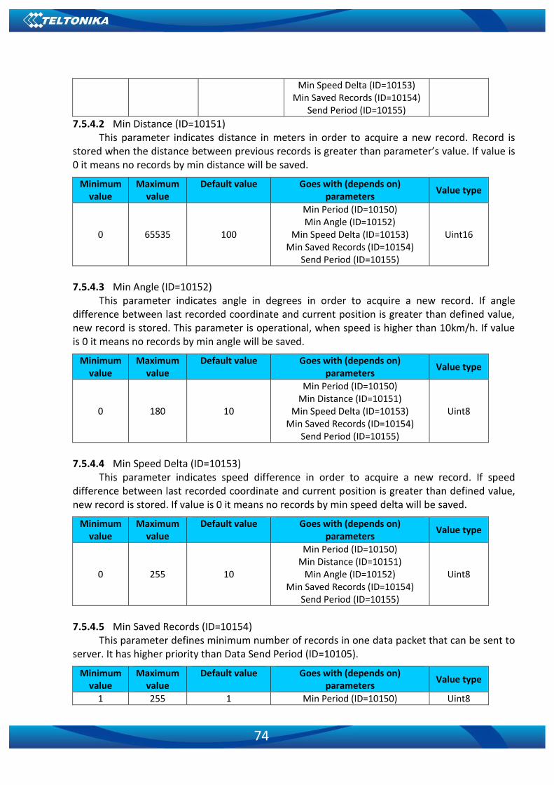
74
Min Speed Delta (ID=10153) Min Saved Records (ID=10154)
Send Period (ID=10155)
7.5.4.2 Min Distance (ID=10151) This parameter indicates distance in meters in order to acquire a new record. Record is
stored when the distance between previous records is greater than parameter’s value. If value is 0 it means no records by min distance will be saved.
Minimum value
Maximum value
Default value Goes with (depends on) parameters
Value type
0 65535 100
Min Period (ID=10150) Min Angle (ID=10152)
Min Speed Delta (ID=10153) Min Saved Records (ID=10154)
Send Period (ID=10155)
Uint16
7.5.4.3 Min Angle (ID=10152)
This parameter indicates angle in degrees in order to acquire a new record. If angle difference between last recorded coordinate and current position is greater than defined value, new record is stored. This parameter is operational, when speed is higher than 10km/h. If value is 0 it means no records by min angle will be saved.
Minimum value
Maximum value
Default value Goes with (depends on) parameters
Value type
0 180 10
Min Period (ID=10150) Min Distance (ID=10151)
Min Speed Delta (ID=10153) Min Saved Records (ID=10154)
Send Period (ID=10155)
Uint8
7.5.4.4 Min Speed Delta (ID=10153)
This parameter indicates speed difference in order to acquire a new record. If speed difference between last recorded coordinate and current position is greater than defined value, new record is stored. If value is 0 it means no records by min speed delta will be saved.
Minimum value
Maximum value
Default value Goes with (depends on) parameters
Value type
0 255 10
Min Period (ID=10150) Min Distance (ID=10151)
Min Angle (ID=10152) Min Saved Records (ID=10154)
Send Period (ID=10155)
Uint8
7.5.4.5 Min Saved Records (ID=10154)
This parameter defines minimum number of records in one data packet that can be sent to server. It has higher priority than Data Send Period (ID=10105).
Minimum value
Maximum value
Default value Goes with (depends on) parameters
Value type
1 255 1 Min Period (ID=10150) Uint8
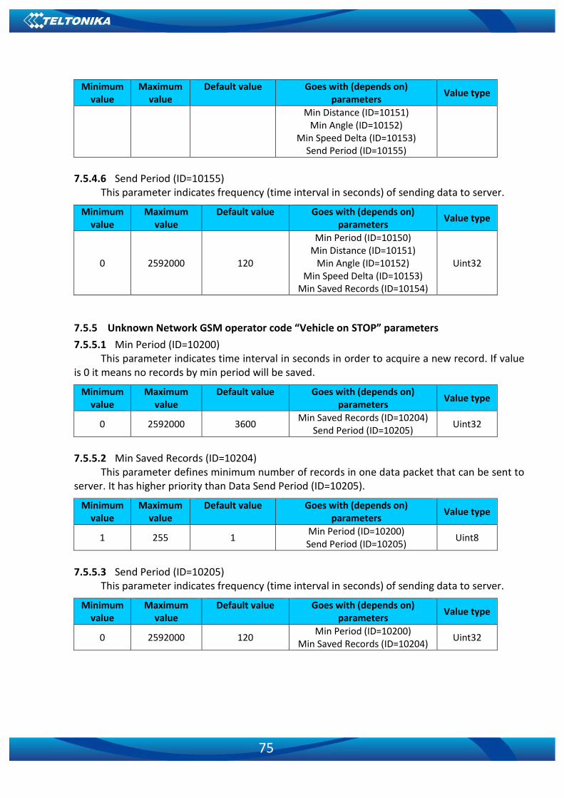
75
Minimum value
Maximum value
Default value Goes with (depends on) parameters
Value type
Min Distance (ID=10151) Min Angle (ID=10152)
Min Speed Delta (ID=10153) Send Period (ID=10155)
7.5.4.6 Send Period (ID=10155)
This parameter indicates frequency (time interval in seconds) of sending data to server.
Minimum value
Maximum value
Default value Goes with (depends on) parameters
Value type
0 2592000 120
Min Period (ID=10150) Min Distance (ID=10151)
Min Angle (ID=10152) Min Speed Delta (ID=10153)
Min Saved Records (ID=10154)
Uint32
7.5.5 Unknown Network GSM operator code “Vehicle on STOP” parameters
7.5.5.1 Min Period (ID=10200) This parameter indicates time interval in seconds in order to acquire a new record. If value
is 0 it means no records by min period will be saved.
Minimum value
Maximum value
Default value Goes with (depends on) parameters
Value type
0 2592000 3600 Min Saved Records (ID=10204)
Send Period (ID=10205) Uint32
7.5.5.2 Min Saved Records (ID=10204)
This parameter defines minimum number of records in one data packet that can be sent to server. It has higher priority than Data Send Period (ID=10205).
Minimum value
Maximum value
Default value Goes with (depends on) parameters
Value type
1 255 1 Min Period (ID=10200) Send Period (ID=10205)
Uint8
7.5.5.3 Send Period (ID=10205)
This parameter indicates frequency (time interval in seconds) of sending data to server.
Minimum value
Maximum value
Default value Goes with (depends on) parameters
Value type
0 2592000 120 Min Period (ID=10200)
Min Saved Records (ID=10204) Uint32

76
7.5.6 Unknown Network GSM operator code “Vehicle MOVING” parameters
7.5.6.1 Min Period (ID=10250) This parameter indicates time interval in seconds in order to acquire a new record. If value
is 0 it means no records by min period will be saved.
Minimum value
Maximum value
Default value Goes with (depends on) parameters
Value type
0 2592000 300
Min Distance (ID=10251) Min Angle (ID=10252) Min Speed (ID=10253)
Min Saved Records (ID=10254) Send Period (ID=10255)
Uint32
7.5.6.2 Min Distance (ID=10251)
This parameter indicates distance in meters in order to acquire a new record. Record is stored when the distance between previous records is greater than parameter’s value. If value is 0 it means no records by min distance will be saved.
Minimum value
Maximum value
Default value Goes with (depends on) parameters
Value type
0 65535 100
Min Period (ID=10250) Min Angle (ID=10252) Min Speed (ID=10253)
Min Saved Records (ID=10254) Send Period (ID=10255)
Uint16
7.5.6.3 Min Angle (ID=10252)
This parameter indicates angle in degrees in order to acquire a new record. If angle difference between last recorded coordinate and current position is greater than defined value, new record is stored. This parameter is operational, when speed is higher than 10km/h. If value is 0 it means no records by min angle will be saved.
Minimum value
Maximum value
Default value Goes with (depends on) parameters
Value type
0 180 10
Min Period (ID=10250) Min Distance (ID=10251)
Min Speed (ID=10253) Min Saved Records (ID=10254)
Send Period (ID=10255)
Uint8
7.5.6.4 Min Speed (ID=10253)
This parameter indicates speed difference in order to acquire a new record. If speed difference between last recorded coordinate and current position is greater than defined value, new record is stored. If value is 0 it means no records by min speed delta will be saved.
Minimum value
Maximum value
Default value Goes with (depends on) parameters
Value type
0 255 10 Min Period (ID=10250)
Min Distance (ID=10251) Uint8

77
Min Angle (ID=10252) Min Saved Records (ID=10254)
Send Period (ID=10255)
7.5.6.5 Min Saved Records (ID=10254)
This parameter defines minimum number of records in one data packet that can be sent to server. It has higher priority than Data Send Period (ID=10105).
Minimum value
Maximum value
Default value Goes with (depends on) parameters
Value type
1 255 1
Min Period (ID=10250) Min Distance (ID=10251)
Min Angle (ID=10252) Min Speed (ID=10253)
Send Period (ID=10255)
Uint8
7.5.6.6 Send Period (ID=10255)
This parameter indicates frequency (time interval in seconds) of sending data to server.
Minimum value
Maximum value
Default value Goes with (depends on) parameters
Value type
0 2592000 120
Min Period (ID=10250) Min Distance (ID=10251)
Min Angle (ID=10252) Min Speed (ID=10253)
Min Saved Records (ID=10254)
Uint32
7.6 Features Parameters
7.6.1 Alarm
7.6.1.1 Scenario Settings (ID=11710) Scenario: 0 – Disabled; 1 – Enable.
Minimum value
Maximum value
Default value Goes with (depends on) parameters
Value type
0 1 0 GSM Predefined Numbers
(ID=6000-6009) Uint8
7.6.1.2 Send SMS To (ID=7245)
Enables/disables SMS. 0 – Disable; 1-10 – SMS will be sent to configured GSM number.
Minimum value
Maximum value
Default value Goes with (depends on) parameters
Value type
0 10 0 GSM Predefined Numbers
(ID=6000-6009) Uint8
7.6.1.3 SMS Text (ID=8245)
Configures alarm SMS event text.

78
Minimum value
Maximum value
Default value Goes with (depends on) parameters
Value type
0 160 char Alarm S8[160]
7.6.1.4 Call Settings (ID=11711) Scenario: 0 – Disabled; 1 – Enable.
Minimum value
Maximum value
Default value Goes with (depends on) parameters
Value type
0 1 0 GSM Predefined Numbers
(ID=6000-6009) Uint8
7.6.1.5 Call to (ID=11712)
Enables/disables the call event. 0 – Disable; 1-10 – SMS will be sent to configured GSM number.
Minimum value
Maximum value
Default value Goes with (depends on) parameters
Value type
0 10 0 GSM Predefined Numbers
(ID=6000-6009) Uint8
7.6.2 Overspeeding scenario parameters
7.6.2.1 Overspeeding priority (ID=11100) Defines priority of overspeeding scenario: 0 – Disabled; 1 – Low; 2 – High; 3 – Panic.
Minimum value
Maximum value
Default value Goes with (depends on) parameters
Value type
0 3 0
Max allowed Speed (ID=11104) Over Speeding Send SMS To
(ID=7032) Over Speeding SMS Text (ID=8032)
Uint8
7.6.2.2 Max Speed (ID=11104)
Maximum allowed speed, an event will occur when this value is exceeded.
Minimum value
Maximum value
Default value Goes with (depends on) parameters
Value type
0 260 90
Overspeeding priority (ID=11100) Over Speeding Send SMS To
(ID=7032) Over Speeding SMS Text (ID=8032)
Uint16
7.6.2.3 Overspeeding Send SMS To (ID=7032)
Enables/disables SMS. 0 – Disable; 1-10 – SMS will be sent to configured GSM number.
Minimum value
Maximum value
Default value Goes with (depends on) parameters
Value type
0 10 0 Overspeeding priority (ID=11100)
Max allowed Speed (ID=11104) UInt8
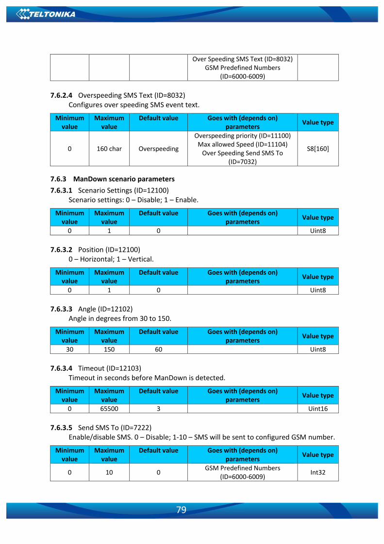
79
Over Speeding SMS Text (ID=8032) GSM Predefined Numbers
(ID=6000-6009)
7.6.2.4 Overspeeding SMS Text (ID=8032)
Configures over speeding SMS event text.
Minimum value
Maximum value
Default value Goes with (depends on) parameters
Value type
0 160 char Overspeeding
Overspeeding priority (ID=11100) Max allowed Speed (ID=11104)
Over Speeding Send SMS To (ID=7032)
S8[160]
7.6.3 ManDown scenario parameters
7.6.3.1 Scenario Settings (ID=12100) Scenario settings: 0 – Disable; 1 – Enable.
Minimum value
Maximum value
Default value Goes with (depends on) parameters
Value type
0 1 0 Uint8
7.6.3.2 Position (ID=12100) 0 – Horizontal; 1 – Vertical.
Minimum value
Maximum value
Default value Goes with (depends on) parameters
Value type
0 1 0 Uint8 7.6.3.3 Angle (ID=12102)
Angle in degrees from 30 to 150.
Minimum value
Maximum value
Default value Goes with (depends on) parameters
Value type
30 150 60 Uint8
7.6.3.4 Timeout (ID=12103) Timeout in seconds before ManDown is detected.
Minimum value
Maximum value
Default value Goes with (depends on) parameters
Value type
0 65500 3 Uint16
7.6.3.5 Send SMS To (ID=7222) Enable/disable SMS. 0 – Disable; 1-10 – SMS will be sent to configured GSM number.
Minimum value
Maximum value
Default value Goes with (depends on) parameters
Value type
0 10 0 GSM Predefined Numbers
(ID=6000-6009) Int32
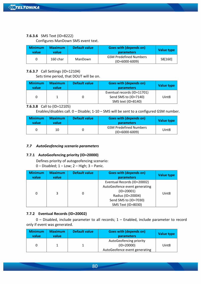
80
7.6.3.6 SMS Text (ID=8222)
Configures ManDown SMS event text.
Minimum value
Maximum value
Default value Goes with (depends on) parameters
Value type
0 160 char ManDown GSM Predefined Numbers
(ID=6000-6009) S8[160]
7.6.3.7 Call Settings (ID=12104)
Sets time period, that DOUT will be on.
Minimum value
Maximum value
Default value Goes with (depends on) parameters
Value type
0 1 0 Eventual records (ID=11701)
Send SMS to (ID=7140) SMS text (ID=8140)
Uint8
7.6.3.8 Call to (ID=12105) Enables/disables call. 0 – Disable; 1-10 – SMS will be sent to a configured GSM number.
Minimum value
Maximum value
Default value Goes with (depends on) parameters
Value type
0 10 0 GSM Predefined Numbers
(ID=6000-6009) Uint8
7.7 AutoGeofencing scenario parameters
7.7.1 AutoGeofencing priority (ID=20000)
Defines priority of autogeofencing scenario: 0 – Disabled; 1 – Low; 2 – High; 3 – Panic.
Minimum value
Maximum value
Default value Goes with (depends on) parameters
Value type
0 3 0
Eventual Records (ID=20002) AutoGeofence event generating
(ID=20001) Radius (ID=20004)
Send SMS to (ID=7030) SMS Text (ID=8030)
Uint8
7.7.2 Eventual Records (ID=20002)
0 – Disabled, include parameter to all records; 1 – Enabled, include parameter to record only if event was generated.
Minimum value
Maximum value
Default value Goes with (depends on) parameters
Value type
0 1 1 AutoGeofencing priority
(ID=20000) AutoGeofence event generating
Uint8

81
(ID=20001) Radius (ID=20004)
Send SMS to (ID=7030) SMS Text (ID=8030)
7.7.3 AutoGeofence event generating (ID=20001)
Generate event: 0 – On exiting zone; 1 – On entering zone; 2 – On both.
Minimum value
Maximum value
Default value Goes with (depends on) parameters
Value type
0 2 0
AutoGeofencing priority (ID=20000)
Eventual Records (ID=20002) Radius (ID=20004)
Send SMS to (ID=7030) SMS Text (ID=8030)
Uint8
7.7.4 Radius (ID=20004)
This parameter represents the radius of a circle with device coordinates after activating AutoGeofence feature.
Minimum value
Maximum value
Default value Goes with (depends on) parameters
Value type
0 1000000 100
AutoGeofencing priority (ID=20000)
Eventual Records (ID=20002) AutoGeofence event generating
(ID=20001) Send SMS to (ID=7030)
SMS Text (ID=8030)
Uint32
7.7.5 AutoGeofence Send SMS to (ID=7030)
Enables/disables SMS. 0 – Disable; 1-10 – SMS will be sent to configured GSM number.
Minimum value
Maximum value
Default value Goes with (depends on) parameters
Value type
0 10 0
AutoGeofencing priority (ID=20000)
Eventual Records (ID=20002) AutoGeofence event generating
(ID=20001) Radius (ID=20004)
SMS Text (ID=8030) GSM Predefined Numbers
(ID=6000-6009)
Uint64
7.7.6 SMS Text (ID=8030)
Configures AutoGeofence SMS event text.

82
Minimum value
Maximum value
Default value Goes with (depends on) parameters
Value type
0 160 AutoGeofence
AutoGeofencing priority (ID=20000)
Eventual Records (ID=20002) AutoGeofence event generating
(ID=20001) Radius (ID=20004)
Send SMS to (ID=7030)
S8[180]
7.7.7 Call Settings (ID=12104)
Sets time period, that DOUT will be on.
Minimum value
Maximum value
Default value Goes with (depends on) parameters
Value type
0 1 0 Eventual records (ID=11701)
Send SMS to (ID=7140) SMS text (ID=8140)
Uint8
7.7.8 Call to (ID=12105)
Enables/disables call. 0 – Disable; 1-10 – SMS will be sent to configured GSM number.
Minimum value
Maximum value
Default value Goes with (depends on) parameters
Value type
0 10 0 GSM Predefined Numbers
(ID=6000-6009) Uint8
7.8 Manual Geofence
7.8.1 First Geozone parameters
An example of first Geozone parameters is given here. All 50 geozones are configured with a similar logic.
7.8.1.1 #1 Geozone Manual Geofencing priority (ID=20100):
0 – Disabled; 1 – Low; 2 – High; 3 – Panic.
Minimum value
Maximum value
Default value Goes with (depends on) parameters
Value type
0 3 0
#1 Geozone Manual Geofence event generating (ID=20101) #1 Geozone Eventual Records
(ID=20102) #1 Geozone Frame border
(ID=20103) #1 Geozone Shape type (ID=20104)
#1 Geozone Radius (ID=20105) #1 Geozone X1 (ID=20106) #1 Geozone Y1 (ID=20107) #1 Geozone X2 (ID=20108) #1 Geozone X1 (ID=20109)
Uint8

83
Minimum value
Maximum value
Default value Goes with (depends on) parameters
Value type
#1 Geozone OverSpeeding (ID=20110)
#1 Geozone Max allowed speed (ID=20111)
7.8.1.2 #1 Geozone Manual Geofence event generating (ID=20101)
Generate event: 0 – No event; 1 - On exiting zone; 2 – On entering zone; 3 – On both.
Minimum value
Maximum value
Default value Goes with (depends on) parameters
Value type
0 3 0
#1 Geozone Manual Geofencing priority (ID=20100)
#1 Geozone Eventual Records (ID=20102)
#1 Geozone Frame border (ID=20103)
#1 Geozone Shape type (ID=20104) #1 Geozone Radius (ID=20105)
#1 Geozone X1 (ID=20106) #1 Geozone Y1 (ID=20107) #1 Geozone X2 (ID=20108) #1 Geozone X1 (ID=20109) #1 Geozone OverSpeeding
(ID=20110) #1 Geozone Max allowed speed
(ID=20111)
Uint8
7.8.1.3 #1 Geozone Eventual Records (ID=20102)
0 – Disabled, include parameter to all records; 1 – Enabled, include parameter to record only if event was generated.
Minimum value
Maximum value
Default value Goes with (depends on) parameters
Value type
0 1 1
#1 Geozone Manual Geofencing priority (ID=20100)
#1 Geozone Manual Geofence event generating (ID=20101)
#1 Geozone Frame border (ID=20103)
#1 Geozone Shape type (ID=20104) #1 Geozone Radius (ID=20105)
#1 Geozone X1 (ID=20106) #1 Geozone Y1 (ID=20107) #1 Geozone X2 (ID=20108) #1 Geozone X1 (ID=20109) #1 Geozone OverSpeeding
(ID=20110) #1 Geozone Max allowed speed
Uint8

84
(ID=20111)
7.8.1.4 #1 Geozone Frame border (ID=20103)
Frame border is an additional border around Geofence zone.
Minimum value
Maximum value
Default value Goes with (depends on) parameters
Value type
0 1000000 1
#1 Geozone Manual Geofencing priority (ID=20100)
#1 Geozone Manual Geofence event generating (ID=20101) #1 Geozone Eventual Records
(ID=20102) #1 Geozone Shape type (ID=20104)
#1 Geozone Radius (ID=20105) #1 Geozone X1 (ID=20106) #1 Geozone Y1 (ID=20107) #1 Geozone X2 (ID=20108) #1 Geozone X1 (ID=20109) #1 Geozone OverSpeeding
(ID=20110) #1 Geozone Max allowed speed
(ID=20111)
Uint32
7.8.1.5 #1 Geozone Shape type (ID=20104)
Shape type: 0 – Circle; 1 - Rectangle.
Minimum value
Maximum value
Default value Goes with (depends on) parameters
Value type
0 1 0
#1 Geozone Manual Geofencing priority (ID=20100)
#1 Geozone Manual Geofence event generating (ID=20101) #1 Geozone Eventual Records
(ID=20102) #1 Geozone Frame border
(ID=20103) #1 Geozone Radius (ID=20105)
#1 Geozone X1 (ID=20106) #1 Geozone Y1 (ID=20107) #1 Geozone X2 (ID=20108) #1 Geozone X1 (ID=20109) #1 Geozone OverSpeeding
(ID=20110) #1 Geozone Max allowed speed
(ID=20111)
Uint8
7.8.1.6 #1 Geozone Radius (ID=20105)
Radius of circle (in metres) when circular zone is used.

85
Minimum value
Maximum value
Default value Goes with (depends on) parameters
Value type
5 1000000 5
#1 Geozone Manual Geofencing priority (ID=20100)
#1 Geozone Manual Geofence event generating (ID=20101) #1 Geozone Eventual Records
(ID=20102) #1 Geozone Frame border
(ID=20103) #1 Geozone Shape type (ID=20104)
#1 Geozone X1 (ID=20106) #1 Geozone Y1 (ID=20107) #1 Geozone X2 (ID=20108) #1 Geozone X1 (ID=20109) #1 Geozone OverSpeeding
(ID=20110) #1 Geozone Max allowed speed
(ID=20111)
Uint32
7.8.1.7 #1 Geozone X1 (ID=20106)
Geofence zone left bottom corner X coordinate (longitude).
Minimum value
Maximum value
Default value Goes with (depends on) parameters
Value type
-180 180 0
#1 Geozone Manual Geofencing priority (ID=20100)
#1 Geozone Manual Geofence event generating (ID=20101) #1 Geozone Eventual Records
(ID=20102) #1 Geozone Frame border
(ID=20103) #1 Geozone Shape type (ID=20104)
#1 Geozone Radius (ID=20105) #1 Geozone Y1 (ID=20107) #1 Geozone X2 (ID=20108) #1 Geozone X1 (ID=20109) #1 Geozone OverSpeeding
(ID=20110) #1 Geozone Max allowed speed
(ID=20111)
Double
7.8.1.8 #1 Geozone Y1 (ID=20107)
Geofence zone left bottom corner Y coordinate (latitude).
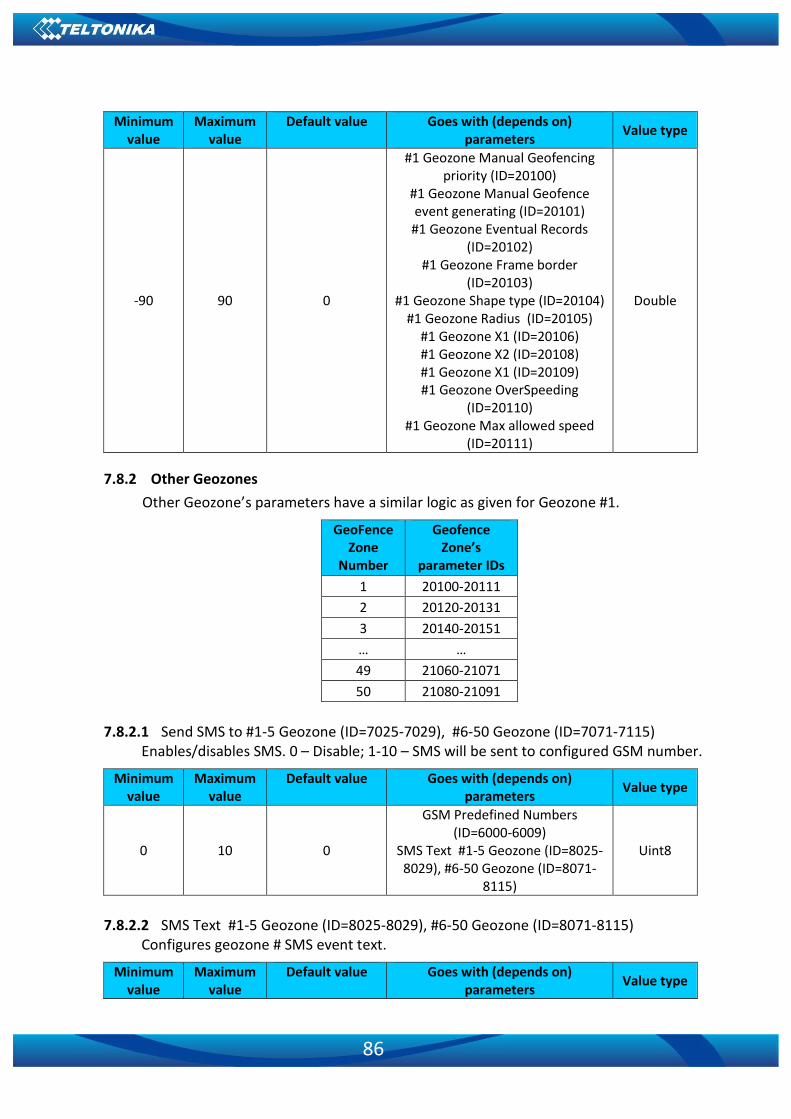
86
Minimum value
Maximum value
Default value Goes with (depends on) parameters
Value type
-90 90 0
#1 Geozone Manual Geofencing priority (ID=20100)
#1 Geozone Manual Geofence event generating (ID=20101) #1 Geozone Eventual Records
(ID=20102) #1 Geozone Frame border
(ID=20103) #1 Geozone Shape type (ID=20104)
#1 Geozone Radius (ID=20105) #1 Geozone X1 (ID=20106) #1 Geozone X2 (ID=20108) #1 Geozone X1 (ID=20109) #1 Geozone OverSpeeding
(ID=20110) #1 Geozone Max allowed speed
(ID=20111)
Double
7.8.2 Other Geozones
Other Geozone’s parameters have a similar logic as given for Geozone #1.
GeoFence Zone
Number
Geofence Zone’s
parameter IDs
1 20100-20111
2 20120-20131
3 20140-20151
… …
49 21060-21071
50 21080-21091
7.8.2.1 Send SMS to #1-5 Geozone (ID=7025-7029), #6-50 Geozone (ID=7071-7115)
Enables/disables SMS. 0 – Disable; 1-10 – SMS will be sent to configured GSM number.
Minimum value
Maximum value
Default value Goes with (depends on) parameters
Value type
0 10 0
GSM Predefined Numbers (ID=6000-6009)
SMS Text #1-5 Geozone (ID=8025-8029), #6-50 Geozone (ID=8071-
8115)
Uint8
7.8.2.2 SMS Text #1-5 Geozone (ID=8025-8029), #6-50 Geozone (ID=8071-8115)
Configures geozone # SMS event text.
Minimum value
Maximum value
Default value Goes with (depends on) parameters
Value type

87
Minimum value
Maximum value
Default value Goes with (depends on) parameters
Value type
0 160 Geozone Zone # Send SMS to #1-5 Geozone
(ID=7025-7029), #6-50 Geozone (ID=7071-7115)
S8[160]
7.9 User Interface
7.9.1 Indication Scenario (12500)
0 – Disabled; 1 – Enabled.
Minimum value
Maximum value
Default value Goes with (depends on) parameters
Value type
0 1 1 Uint8
7.9.2 Sleep Config (12501)
0 – Undefined; 1 – GPS; 2 – Deep; 3 – Online Deep; 4 - Ultra Deep; 5 – GPS + Online Deep; 6 – Deep + Online Deep; 7 – GPS + Deep + Online Deep; 8 – Ultra Deep; 9 – GPS + Ultra Deep; 10 – Deep + Ultra Deep; 11 – GPS + Deep + Ultra Deep; 12 – Online Deep + Ultra Deep; 13 – GPS + Online Deep + Ultra Deep; 14 – Deep + Online Deep + Ultra Deep; 15 – GPS + Deep + Online Deep + Ultra Deep.
Minimum value
Maximum value
Default value Goes with (depends on) parameters
Value type
0 15 0 Uint8
7.9.3 Led (12502)
0 – Red; 1 – Green; 2 – Blue; 3 – None.
Minimum value
Maximum value
Default value Goes with (depends on) parameters
Value type
0 3 0 Uint8
7.9.4 Vibration (12503)
0 – Disabled; 1 – Enabled.
Minimum value
Maximum value
Default value Goes with (depends on) parameters
Value type
0 1 0 Uint8
7.9.5 Period (12504)
LED and vibration period in seconds.
Minimum value
Maximum value
Default value Goes with (depends on) parameters
Value type
0 3600 15 Uint8

88
7.9.6 On (ms) (12505)
LED and vibration switching in milliseconds.
Minimum value
Maximum value
Default value Goes with (depends on) parameters
Value type
0 10000 2000 Uint32
7.9.7 Off (ms) (12506)
LED and vibration shutdown in milliseconds.
Minimum value
Maximum value
Default value Goes with (depends on) parameters
Value type
0 10000 0 Uint32
7.9.8 Repeat (12507)
Minimum value
Maximum value
Default value Goes with (depends on) parameters
Value type
0 100 0 Uint32
Table 6. Parameters for GH5200 User Interface
Parameter ID
Parameter Type
Default value
Value range Parameter name
Min Max
12500 Uint8 1 0 1 GSM Error Setting 12501 Uint8 0 0 15 GSM Error Config 12502 Uint8 0 0 3 GSM Error LED 12503 Uint8 0 0 1 GSM Error Vibration 12504 Uint8 15 0 3600 GSM Error Period 12505 Uint32 2000 0 10000 GSM Error On (ms) 12506 Uint32 0 0 10000 GSM Error Off (ms) 12507 Uint32 0 0 100 GSM Error Repeat 12510 Uint8 1 0 1 GSM Registering Setting 12511 Uint8 0 0 15 GSM Registering Config 12512 Uint8 0 0 3 GSM Registering LED 12513 Uint8 0 0 1 GSM Registering Vibration 12514 Uint8 15 0 3600 GSM Registering Period 12515 Uint32 2000 0 10000 GSM Registering On (ms) 12516 Uint32 0 0 10000 GSM Registering Off (ms) 12517 Uint32 0 0 100 GSM Registering Repeat 12520 Uint8 1 0 1 GSM Send/Receive Setting 12521 Uint8 0 0 15 GSM Send/Receive Config 12522 Uint8 0 0 3 GSM Send/Receive LED 12523 Uint8 0 0 1 GSM Send/Receive Vibration 12525 Uint32 2000 0 10000 GSM Send/Receive On (ms) 12526 Uint32 0 0 10000 GSM Send/Receive Off (ms) 12527 Uint32 0 0 100 GSM Send/Receive Repeat 12530 Uint8 1 0 1 Outgoing Call Setting 12531 Uint8 0 0 15 Outgoing Call Config

89
Parameter ID
Parameter Type
Default value
Value range Parameter name
Min Max
12532 Uint8 0 0 3 Outgoing Call LED 12533 Uint8 0 0 1 Outgoing Call Vibration 12534 Uint8 15 0 3600 Outgoing Call Period 12535 Uint32 2000 0 10000 Outgoing Call On (ms) 12536 Uint32 0 0 10000 Outgoing Call Off (ms) 12537 Uint32 0 0 100 Outgoing Call Repeat 12540 Uint8 1 0 1 Remote Connection Setting 12541 Uint8 0 0 15 Remote Connection Config 12542 Uint8 0 0 3 Remote Connection LED 12543 Uint8 0 0 1 Remote Connection Vibration 12544 Uint8 15 0 3600 Remote Connection Period 12545 Uint32 2000 0 10000 Remote Connection On (ms) 12546 Uint32 0 0 10000 Remote Connection Off (ms) 12547 Uint32 0 0 100 Remote Connection Repeat 12550 Uint8 1 0 1 Event Setting 12551 Uint8 0 0 15 Event Config 12552 Uint8 0 0 3 Event LED 12553 Uint8 0 0 1 Event Vibration 12555 Uint32 2000 0 10000 Event On (ms) 12556 Uint32 0 0 10000 Event Off (ms) 12557 Uint32 0 0 100 Event Repeat 12560 Uint8 1 0 1 Panic Event Setting 12561 Uint8 0 0 15 Panic Event Config 12562 Uint8 0 0 3 Panic Event LED 12563 Uint8 0 0 1 Panic Event Vibration 12565 Uint32 2000 0 10000 Panic Event On (ms) 12566 Uint32 0 0 10000 Panic Event Off (ms) 12567 Uint32 0 0 100 Panic Event Repeat 12570 Uint8 1 0 1 No GPS Fix Setting 12571 Uint8 0 0 15 No GPS Fix Config 12572 Uint8 0 0 3 No GPS Fix LED 12573 Uint8 0 0 1 No GPS Fix Vibration 12574 Uint8 15 0 3600 No GPS Fix Period 12575 Uint32 2000 0 10000 No GPS Fix On (ms) 12576 Uint32 0 0 10000 No GPS Fix Off (ms) 12577 Uint32 0 0 100 No GPS Fix Repeat 12580 Uint8 1 0 1 GPS Fix Setting 12581 Uint8 0 0 15 GPS Fix Config 12582 Uint8 0 0 3 GPS Fix LED 12583 Uint8 0 0 1 GPS Fix Vibration 12584 Uint8 15 0 3600 GPS Fix Period 12585 Uint32 2000 0 10000 GPS Fix On (ms) 12586 Uint32 0 0 10000 GPS Fix Off (ms) 12587 Uint32 0 0 100 GPS Fix Repeat 12590 Uint8 1 0 1 Device Off Setting 12591 Uint8 0 0 15 Device Off Config

90
Parameter ID
Parameter Type
Default value
Value range Parameter name
Min Max
12592 Uint8 0 0 3 Device Off LED 12593 Uint8 0 0 1 Device Off Vibration 12595 Uint32 2000 0 10000 Device Off On (ms) 12596 Uint32 0 0 10000 Device Off Off (ms) 12597 Uint32 0 0 100 Device Off Repeat 12600 Uint8 1 0 1 Device On Setting 12601 Uint8 0 0 15 Device On Config 12602 Uint8 0 0 3 Device On LED 12603 Uint8 0 0 1 Device On Vibration 12605 Uint32 2000 0 10000 Device On On (ms) 12606 Uint32 0 0 10000 Device On Off (ms) 12607 Uint32 0 0 100 Device On Repeat 12610 Uint8 1 0 1 Alarm Key Pressed Setting 12611 Uint8 0 0 15 Alarm Key Pressed Config 12612 Uint8 0 0 3 Alarm Key Pressed LED 12613 Uint8 0 0 1 Alarm Key Pressed Vibration 12614 Uint8 15 0 3600 Alarm Key Pressed Period 12615 Uint32 2000 0 10000 Alarm Key Pressed On (ms) 12616 Uint32 0 0 10000 Alarm Key Pressed Off (ms) 12617 Uint32 0 0 100 Alarm Key Pressed Repeat 12620 Uint8 1 0 1 Power Key Pressed Setting 12621 Uint8 0 0 15 Power Key Pressed Config 12622 Uint8 0 0 3 Power Key Pressed LED 12623 Uint8 0 0 1 Power Key Pressed Vibration 12624 Uint8 15 0 3600 Power Key Pressed Period 12625 Uint32 2000 0 10000 Power Key Pressed On (ms) 12626 Uint32 0 0 10000 Power Key Pressed Off (ms) 12627 Uint32 0 0 100 Power Key Pressed Repeat 12630 Uint8 1 0 1 Function Activated Setting 12631 Uint8 0 0 15 Function Activated Config 12632 Uint8 0 0 3 Function Activated LED 12633 Uint8 0 0 1 Function Activated Vibration 12635 Uint32 2000 0 10000 Function Activated On (ms) 12636 Uint32 0 0 10000 Function Activated Off (ms) 12637 Uint32 0 0 100 Function Activated Repeat 12640 Uint8 1 0 1 Function Deactivated Setting 12641 Uint8 0 0 15 Function Deactivated Config 12642 Uint8 0 0 3 Function Deactivated LED 12643 Uint8 0 0 1 Function Deactivated Vibration 12645 Uint32 2000 0 10000 Function Deactivated On (ms) 12646 Uint32 0 0 10000 Function Deactivated Off (ms) 12647 Uint32 0 0 100 Function Deactivated Repeat 12650 Uint8 1 0 1 Charging Setting 12651 Uint8 0 0 15 Charging Config 12652 Uint8 0 0 3 Charging LED 12653 Uint8 0 0 1 Charging Vibration
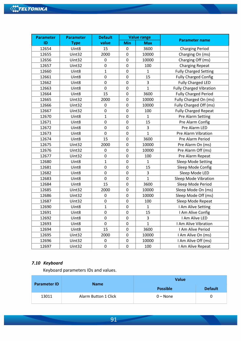
91
Parameter ID
Parameter Type
Default value
Value range Parameter name
Min Max
12654 Uint8 15 0 3600 Charging Period 12655 Uint32 2000 0 10000 Charging On (ms) 12656 Uint32 0 0 10000 Charging Off (ms) 12657 Uint32 0 0 100 Charging Repeat 12660 Uint8 1 0 1 Fully Charged Setting 12661 Uint8 0 0 15 Fully Charged Config 12662 Uint8 0 0 3 Fully Charged LED 12663 Uint8 0 0 1 Fully Charged Vibration 12664 Uint8 15 0 3600 Fully Charged Period 12665 Uint32 2000 0 10000 Fully Charged On (ms) 12666 Uint32 0 0 10000 Fully Charged Off (ms) 12667 Uint32 0 0 100 Fully Charged Repeat 12670 Uint8 1 0 1 Pre Alarm Setting 12671 Uint8 0 0 15 Pre Alarm Config 12672 Uint8 0 0 3 Pre Alarm LED 12673 Uint8 0 0 1 Pre Alarm Vibration 12674 Uint8 15 0 3600 Pre Alarm Period 12675 Uint32 2000 0 10000 Pre Alarm On (ms) 12676 Uint32 0 0 10000 Pre Alarm Off (ms) 12677 Uint32 0 0 100 Pre Alarm Repeat 12680 Uint8 1 0 1 Sleep Mode Setting 12681 Uint8 0 0 15 Sleep Mode Config 12682 Uint8 0 0 3 Sleep Mode LED 12683 Uint8 0 0 1 Sleep Mode Vibration 12684 Uint8 15 0 3600 Sleep Mode Period 12685 Uint32 2000 0 10000 Sleep Mode On (ms) 12686 Uint32 0 0 10000 Sleep Mode Off (ms) 12687 Uint32 0 0 100 Sleep Mode Repeat 12690 Uint8 1 0 1 I Am Alive Setting 12691 Uint8 0 0 15 I Am Alive Config 12692 Uint8 0 0 3 I Am Alive LED 12693 Uint8 0 0 1 I Am Alive Vibration 12694 Uint8 15 0 3600 I Am Alive Period 12695 Uint32 2000 0 10000 I Am Alive On (ms) 12696 Uint32 0 0 10000 I Am Alive Off (ms) 12697 Uint32 0 0 100 I Am Alive Repeat
7.10 Keyboard
Keyboard parameters IDs and values.
Parameter ID Name Value
Possible Default
13011 Alarm Button 1 Click 0 – None 0
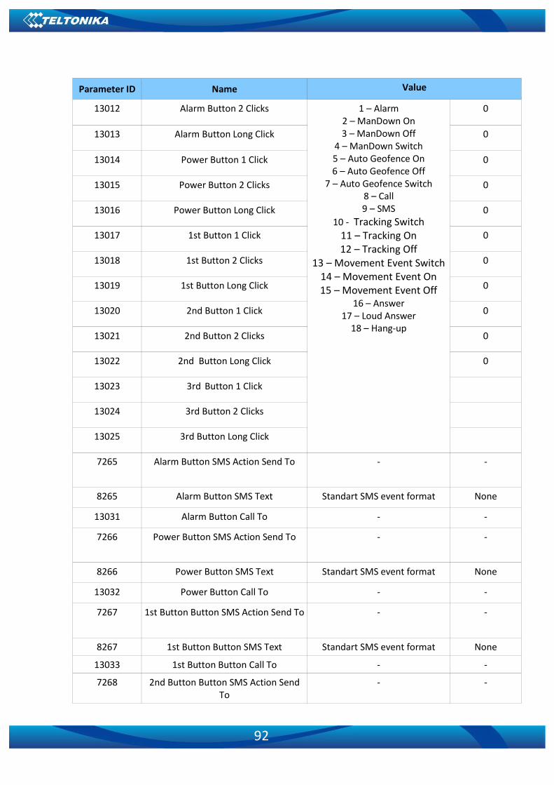
92
Parameter ID Name Value
13012 Alarm Button 2 Clicks 1 – Alarm 2 – ManDown On 3 – ManDown Off
4 – ManDown Switch 5 – Auto Geofence On 6 – Auto Geofence Off
7 – Auto Geofence Switch 8 – Call 9 – SMS
10 - Tracking Switch 11 – Tracking On 12 – Tracking Off
13 – Movement Event Switch 14 – Movement Event On 15 – Movement Event Off
16 – Answer 17 – Loud Answer
18 – Hang-up
0
13013 Alarm Button Long Click 0
13014 Power Button 1 Click 0
13015 Power Button 2 Clicks 0
13016 Power Button Long Click 0
13017 1st Button 1 Click 0
13018 1st Button 2 Clicks 0
13019 1st Button Long Click 0
13020 2nd Button 1 Click 0
13021 2nd Button 2 Clicks 0
13022 2nd Button Long Click 0
13023 3rd Button 1 Click
13024 3rd Button 2 Clicks
13025 3rd Button Long Click
7265 Alarm Button SMS Action Send To - -
8265 Alarm Button SMS Text Standart SMS event format None
13031 Alarm Button Call To - -
7266 Power Button SMS Action Send To - -
8266 Power Button SMS Text Standart SMS event format None
13032 Power Button Call To - -
7267 1st Button Button SMS Action Send To - -
8267 1st Button Button SMS Text Standart SMS event format None
13033 1st Button Button Call To - -
7268 2nd Button Button SMS Action Send To
- -

93
Parameter ID Name Value
8268 2nd Button Button SMS Text Standart SMS event format None
13034 2nd Button Button Call To - -
7269 3rd Button Button SMS Action Send To
- -
8269 3rd Button Button SMS Text Standart SMS event format None
13035 3rd Button Button Call To - -
7.11 Actions
7.11.1 SMS Action
7.11.1.1 SMS Send to (7249) Enables/disables SMS. 0 – Disable; 1-10 – SMS will be sent to configured GSM number.
Minimum value
Maximum value
Default value Goes with (depends on) parameters
Value type
0 10 0 GSM Predefined Numbers
(ID=6000-6009) Int32
7.11.1.2 SMS Text (8249)
Configures Keyboard SMS event text.
Minimum value
Maximum value
Default value Goes with (depends on) parameters
Value type
0 160 char Keyboard GSM Predefined Numbers
(ID=6000-6009) S8[160]
7.11.2 Call Action
7.11.2.1 Call to (13010) Enables/disables call. 0 – Disable; 1-10 – SMS will be sent to configured GSM number.
Minimum value
Maximum value
Default value Goes with (depends on) parameters
Value type
0 10 0 GSM Predefined Numbers
(ID=6000-6009) Uint8
7.12 Bluetooth
7.12.1.1 BT Radio (ID=800) Enables/disables Bluetooth. 0 – Disabled; 1 – Enabled (hidden); 2 – Enabled (visible).
Minimum value
Maximum value
Default value Goes with (depends on) parameters
Value type
0
2 0 Local name (ID 801) Local PIN (ID=802)
Uint8

94
Security mode (ID=803) External MAC (ID=804) External name (ID=805) External PIN (ID=806)
Connection mode (ID=807) Authorized devices MAC list
(ID=830 - 834)
7.12.1.2 Local name (ID 801)
This parameter defines the visible name of GH5200 device.
Minimum value
Maximum value
Default value Goes with (depends on) parameters
Value type
0 Symbols 30 Symbols GH5200_(last 7 IMEI numbers)
BT Radio (ID=800) Local PIN (ID=802)
Security mode (ID=803) External MAC (ID=804) External name (ID=805) External PIN (ID=806)
Connection mode (ID=807) Authorized devices MAC list
(ID=830 - 834)
S8[30]
7.12.1.3 Local PIN (ID=802)
Parameter allows configuring Bluetooth PIN.
Minimum value
Maximum value
Default value Goes with (depends on) parameters
Value type
0 Symbols 4 Symbols 5555
BT Radio (ID=800) Local name (ID 801)
Security mode (ID=803) External MAC (ID=804) External name (ID=805) External PIN (ID=806)
Connection mode (ID=807) Authorized devices MAC list
(ID=830 - 834)
String
7.12.1.4 Security mode (ID=803)
Parameter defines a security mode of GH5200 device. 0 – PIN only; 1 – PIN and MAC; 2 - MAC only; 3 – None.
Minimum value
Maximum value
Default value Goes with (depends on) parameters
Value type
0 3 0
BT Radio (ID=800) Local name (ID 801) Local PIN (ID=802)
External MAC (ID=804) External name (ID=805) External PIN (ID=806)
Uint8
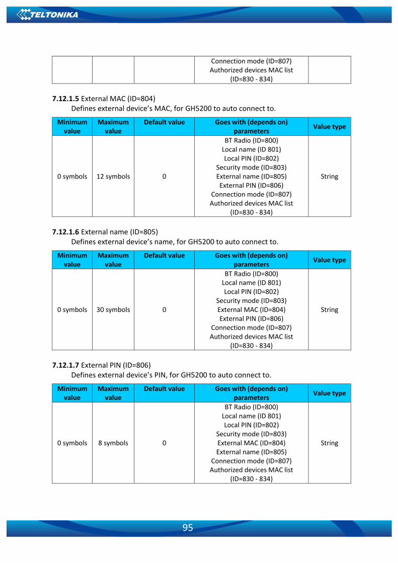
95
Connection mode (ID=807) Authorized devices MAC list
(ID=830 - 834)
7.12.1.5 External MAC (ID=804)
Defines external device’s MAC, for GH5200 to auto connect to.
Minimum value
Maximum value
Default value Goes with (depends on) parameters
Value type
0 symbols 12 symbols 0
BT Radio (ID=800) Local name (ID 801) Local PIN (ID=802)
Security mode (ID=803) External name (ID=805) External PIN (ID=806)
Connection mode (ID=807) Authorized devices MAC list
(ID=830 - 834)
String
7.12.1.6 External name (ID=805)
Defines external device’s name, for GH5200 to auto connect to.
Minimum value
Maximum value
Default value Goes with (depends on) parameters
Value type
0 symbols 30 symbols 0
BT Radio (ID=800) Local name (ID 801) Local PIN (ID=802)
Security mode (ID=803) External MAC (ID=804) External PIN (ID=806)
Connection mode (ID=807) Authorized devices MAC list
(ID=830 - 834)
String
7.12.1.7 External PIN (ID=806)
Defines external device’s PIN, for GH5200 to auto connect to.
Minimum value
Maximum value
Default value Goes with (depends on) parameters
Value type
0 symbols 8 symbols 0
BT Radio (ID=800) Local name (ID 801) Local PIN (ID=802)
Security mode (ID=803) External MAC (ID=804) External name (ID=805)
Connection mode (ID=807) Authorized devices MAC list
(ID=830 - 834)
String

96
7.12.1.8 Connection mode (ID=807) Defines a mode in which GH5200 will connect to external devices. 0 – None, 1 – GH5200
will connect to Hands Free Headset; 2 – Data Link.
Minimum value
Maximum value
Default value Goes with (depends on) parameters
Value type
0 2 0
BT Radio (ID=800) Local name (ID 801) Local PIN (ID=802)
Security mode (ID=803) External MAC (ID=804) External name (ID=805) External PIN (ID=806)
Authorized devices MAC list (ID=830 - 834)
Uint8
7.12.1.9 Authorized devices MAC list (ID=830 - 834) This parameter allows adding an authorized devices MAC for connection to GH5200.
Minimum value
Maximum value
Default value Goes with (depends on) parameters
Value type
0 symbols 12 symbols -
BT Radio (ID=800) Local name (ID 801) Local PIN (ID=802)
Security mode (ID=803) External MAC (ID=804) External name (ID=805) External PIN (ID=806)
Connection mode (ID=807)
String
7.13 I/O parameters
I/O properties are additional data sources which are recorded along with usual GPS data.
7.13.1 I/O#1 property parameter priority (ID=50010)
This parameter defines I/O property priority: 0 – Disabled; 1 – Low; 2 – High; 3 - Panic.
Minimum value
Maximum value
Default value Goes with (depends on) parameters
Value type
0 3 2
I/O#1 operand (ID=50011)I/O#1 High level (ID=50012)
I/O#1 Low level (ID=50013) I/O#1 Event only (ID=50014)
I/O#1 averaging length (ID=50015) I/O#1 send SMS (ID=7000) I/O#1 SMS text (ID=8000)
Uint8
7.13.2 I/O#1 operand (ID=50011)
This parameter defines when event is sent: 0 – On range exit; 1 – On range entrance; 2 – Both; 3 – Monitoring; 4 – Hysteresis; 5 – On changes; 6 – On delta change.

97
Minimum value
Maximum value
Default value Goes with (depends on) parameters
Value type
0 6 5
I/O#1 property parameter priority
(ID=50010)I/O#1 High level (ID=50012)
I/O#1 Low level (ID=50013) I/O#1 Event only (ID=50014)
I/O#1 averaging length (ID=50015) I/O#1 send SMS (ID=7000) I/O#1 SMS text (ID=8000)
Uint8
7.13.3 I/O#1 High level (ID=50012)
This parameter defines high value of triggered I/O property. This parameter is used to set thresholds for I/O properties to generate events.
Minimum value
Maximum value
Default value Goes with (depends on) parameters
Value type
0 1 0
I/O#1 property parameter priority (ID=50010)
I/O#1 operand (ID=50011) I/O#1 Low level (ID=50013)
I/O#1 Event only (ID=50014) I/O#1 averaging length (ID=50015)
I/O#1 send SMS (ID=7000) I/O#1 SMS text (ID=8000)
Uint8
7.13.4 I/O#1 Low level (ID=50013)
This parameter defines low value of triggered I/O property. This parameter is used to set thresholds for I/O properties to generate events.
Minimum value
Maximum value
Default value Goes with (depends on) parameters Value type
0 1 0
I/O#1 property parameter priority (ID=50010)
I/O#1 operand (ID=50011)I/O#1 High level (ID=50012)
I/O#1 Event only (ID=50014) I/O#1 averaging length (ID=50015)
I/O#1 send SMS (ID=7000) I/O#1 SMS text (ID=8000)
Uint8
7.13.5 I/O#1 Event only (ID=50014)
This parameter defines when I/O element value is sent: 0 – With every AVL packet; 1 – On event only. On event means that I/O element value is included to AVL packet only when this particular event happens. With regular, periodic records such I/O element value is not included.
Minimal value
Maximum value
Default value Goes with (depends on) parameters
Value type

98
0 1 0
I/O#1 property parameter priority (ID=50010)
I/O#1 operand (ID=50011)I/O#1 High level (ID=50012)
I/O#1 Low level (ID=50013) I/O#1 averaging length (ID=50015)
I/O#1 send SMS (ID=7000) I/O#1 SMS text (ID=8000)
Uint8
7.13.6 I/O#1 averaging length (ID=50015)
This parameter defines I/O property sample length used for averaging.
Minimum value
Maximum value
Default value Goes with (depends on) parameters
Value type
0 65535 1
I/O#1 property parameter priority (ID=50010)
I/O#1 operand (ID=50011)I/O#1 High level (ID=50012)
I/O#1 Low level (ID=50013) I/O#1 Event only (ID=50014) I/O#1 send SMS (ID=7000) I/O#1 SMS text (ID=8000)
Uint16
7.13.7 I/O#1 send SMS (ID=7001)
Enables/disables SMS. 0 – Disable; 1-10 – SMS will be sent to configured GSM number.
Minimum value
Maximum value
Default value Goes with (depends on) parameters
Value type
0 10 0
GSM Predefined Numbers (ID=6000-6009)
I/O#1 property parameter priority (ID=50010)
I/O#1 operand (ID=50011)I/O#1 High level (ID=50012)
I/O#1 Low level (ID=50013) I/O#1 Event only (ID=50014)
I/O#1 SMS text (ID=8000)
Uint8
7.13.8 I/O#1 SMS text (ID=8001)
Configures I/O#1 SMS event text.
Minimum value
Maximum value
Default value Goes with (depends on) parameters
Value type

99
0 160 Movement
I/O#1 property parameter priority (ID=50010)
I/O#1 operand (ID=50011)I/O#1 High level (ID=50012)
I/O#1 Low level (ID=50013) I/O#1 Event only (ID=50014) I/O#1 send SMS (ID=7000)
S8[160]
7.13.9 I/O elements parameters and types
Priority: 0 – Disabled; 1 – Low; 2 – High; 3 – Panic. Operand: 0 – On Exit; 1 – On Entrance; 2 – On Both; 3 – Monitoring; 4 – On Hysteresis;
5 - On Change; 6 – On Delta Change. Event only: 0 – No; 1 – Yes.
Table 7. Parameters for GH5200 devices
Parameter ID
Parameter Type
Default value
Value range Parameter name
Min Max
50010 Uint8 1 0 3 Movement Priority
50011 Uint8 5 0 6 Movement Operand
50012 Uint8 0 0 1 Movement High level
50013 Uint8 0 0 1 Movement Low level
50014 Uint8 0 0 1 Movement Event only
50015 Uint16 1 0 65535 Movement Average
7001 Uint8 0 0 10 Send SMS
8001 String 0 0 160 SMS Text
50020 Uint8 1 0 3 Data Mode Priority
50021 Uint8 3 0 6 Data Mode Operand
50022 Uint8 0 0 5 Data Mode High level
50023 Uint8 0 0 5 Data Mode Low level
50024 Uint8 0 0 1 Data Mode Event only
7002 Uint8 0 0 10 Send SMS
8002 String 0 0 160 SMS Text 50030 Uint8 1 0 3 GSM Signal Priority 50031 Uint8 3 0 6 GSM Signal Operand 50032 Uint8 0 0 5 GSM Signal High level 50033 Uint8 0 0 5 GSM Signal Low level 50034 Uint8 0 0 1 GSM Signal Event only 50035 Uint16 1 0 65535 GSM Signal Average 7003 Uint8 0 0 10 Send SMS 8003 String 0 0 160 SMS Text
50040 Uint8 1 0 3 Sleep Priority 50041 Uint8 3 0 6 Sleep Operand 50042 Uint8 0 0 2 Sleep High level 50043 Uint8 0 0 2 Sleep Low level 50044 Uint8 0 0 1 Sleep Event only 7004 Uint8 0 0 10 Send SMS

100
Parameter ID
Parameter Type
Default value
Value range Parameter name
Min Max
8004 String 0 0 160 SMS Text 50050 Uint8 1 0 3 GNSS Status Priority 50051 Uint8 3 0 6 GNSS Status Operand 50052 Uint8 0 0 5 GNSS Status High level 50053 Uint8 0 0 5 GNSS Status Low level 50053 Uint8 0 0 1 GNSS Status Event only 7005 Uint8 0 0 10 Send SMS 8005 String 0 0 160 SMS Text
50060 Uint8 0 0 3 GNSS PDOP Priority 5061 Uint8 3 0 6 GNSS PDOP Operand 5062 Uint16 0 0 1000 GNSS PDOP High level 5063 Uint16 0 0 1000 GNSS PDOP Low level 5064 Uint8 0 0 1 GNSS PDOP Event only 5065 Uint16 10 0 65535 GNSS PDOP Average 7006 Uint8 0 0 10 Send SMS 8006 String 0 0 160 SMS Text
50070 Uint8 1 0 3 GNSS HDOP Priority 50071 Uint8 3 0 6 GNSS HDOP Operand 50072 Uint16 0 0 1000 GNSS HDOP High level 50073 Uint16 0 0 1000 GNSS HDOP Low level 50074 Uint8 0 0 1 GNSS HDOP Event only 50075 Uint16 10 0 65535 GNSS HDOP Average 7007 Uint8 0 0 10 Send SMS 8007 String 0 0 160 SMS Text
50100 Uint8 0 0 3 GSM Cell ID Priority 50101 Uint8 3 0 6 GSM Cell ID Operand 50102 Uint32 0 0 999999 GSM Cell ID High level 50103 Uint32 0 0 999999 GSM Cell ID Low level 50104 Uint8 0 0 1 GSM Cell ID Event only 7010 Uint8 0 0 10 Send SMS 8010 String 0 0 160 SMS Text
50110 Uint8 0 0 3 GSM Area Code Priority 50111 Uint8 3 0 6 GSM Area Code Operand 50112 Uint32 0 0 999999 GSM Area Code High level 50113 Uint32 0 0 999999 GSM Area Code Low level 50114 Uint8 0 0 1 GSM Area Code Event only 7011 Uint8 0 0 10 Send SMS 8011 String 0 0 160 SMS Text
50120 Uint8 1 0 3 Battery Voltage Priority 50121 Uint8 3 0 6 Battery Voltage Operand 50122 Uint16 0 0 5000 Battery Voltage High level 50123 Uint16 0 0 5000 Battery Voltage Low level 50124 Uint8 0 0 1 Battery Voltage Event only 50125 Uint8 0 0 10 Battery Voltage Average 7012 Uint8 0 0 10 Send SMS 8012 String 0 0 160 SMS Text

101
Parameter ID
Parameter Type
Default value
Value range Parameter name
Min Max
50660 Uint8 0 0 3 Battery Level Priority 50661 Uint8 3 0 6 Battery Level Operand 50662 Uint16 0 0 1000 Battery Level High level 50663 Uint16 0 0 1000 Battery Level Low level 50664 Uint8 0 0 1 Battery Level Event only 7013 Uint8 0 0 10 Send SMS 8243 String 0 0 160 SMS Text
50140 Uint8 0 0 3 Active GSM Operator Priority 50141 Uint8 3 0 6 Active GSM Operator Operand 50142 Uint32 0 0 999999 Active GSM Operator High level 50143 Uint32 0 0 999999 Active GSM Operator Low level 50144 Uint8 0 0 1 Active GSM Operator Event only 7014 Uint8 0 0 10 Send SMS 8014 String 0 0 160 SMS Text
50150 Uint8 0 0 3 Charger Connected Priority 50151 Uint8 3 0 6 Charger Connected Operand 50152 Uint32 0 0 1 Charger Connected High level 50153 Uint32 0 0 1 Charger Connected Low level 50154 Uint8 0 0 1 Charger Connected Event only 7014 Uint8 0 0 10 Send SMS 8244 String 0 0 160 SMS Text
50160 Uint8 0 0 3 Total Odometer Priority 50161 Uint8 3 0 6 Total Odometer Operand 50162 Uint32 0 0 10000000 Total Odometer High level 50163 Uint32 0 0 10000000 Total Odometer Low level 50164 Uint8 0 0 1 Total Odometer Event only 7016 Uint8 0 0 10 Send SMS 8016 String 0 0 160 SMS Text
50170 Uint8 0 0 3 Digital Input 1 Priority 50171 Uint8 3 0 6 Digital Input 1 Operand 50172 Uint8 0 0 1 Digital Input 1 High level 50173 Uint8 0 0 1 Digital Input 1 Low level 50174 Uint8 0 0 1 Digital Input 1 Event only 50175 Uint16 1 0 65535 Digital Input 1 Average 7017 Uint8 0 0 10 Send SMS 8017 String 0 0 160 SMS Text
50180 Uint8 0 0 3 Analog Input 1 Priority 50181 Uint8 3 0 6 Analog Input 1 Operand 50182 Uint16 0 0 30000 Analog Input 1 High level 50183 Uint16 0 0 30000 Analog Input 1 Low level 50184 Uint8 0 0 1 Analog Input 1 Event only 50185 Uint16 10 0 65535 Analog Input 1 Average 7018 Uint8 0 0 10 Send SMS 8018 String 0 0 160 SMS Text
50190 Uint8 0 0 3 Digital Output 1 Priority 50191 Uint8 0 0 6 Digital Output 1 Operand
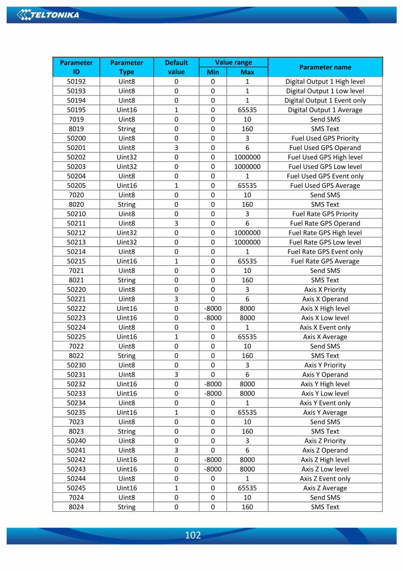
102
Parameter ID
Parameter Type
Default value
Value range Parameter name
Min Max
50192 Uint8 0 0 1 Digital Output 1 High level 50193 Uint8 0 0 1 Digital Output 1 Low level 50194 Uint8 0 0 1 Digital Output 1 Event only 50195 Uint16 1 0 65535 Digital Output 1 Average 7019 Uint8 0 0 10 Send SMS 8019 String 0 0 160 SMS Text
50200 Uint8 0 0 3 Fuel Used GPS Priority 50201 Uint8 3 0 6 Fuel Used GPS Operand 50202 Uint32 0 0 1000000 Fuel Used GPS High level 50203 Uint32 0 0 1000000 Fuel Used GPS Low level 50204 Uint8 0 0 1 Fuel Used GPS Event only 50205 Uint16 1 0 65535 Fuel Used GPS Average 7020 Uint8 0 0 10 Send SMS 8020 String 0 0 160 SMS Text
50210 Uint8 0 0 3 Fuel Rate GPS Priority 50211 Uint8 3 0 6 Fuel Rate GPS Operand 50212 Uint32 0 0 1000000 Fuel Rate GPS High level 50213 Uint32 0 0 1000000 Fuel Rate GPS Low level 50214 Uint8 0 0 1 Fuel Rate GPS Event only 50215 Uint16 1 0 65535 Fuel Rate GPS Average 7021 Uint8 0 0 10 Send SMS 8021 String 0 0 160 SMS Text
50220 Uint8 0 0 3 Axis X Priority 50221 Uint8 3 0 6 Axis X Operand 50222 Uint16 0 -8000 8000 Axis X High level 50223 Uint16 0 -8000 8000 Axis X Low level 50224 Uint8 0 0 1 Axis X Event only 50225 Uint16 1 0 65535 Axis X Average 7022 Uint8 0 0 10 Send SMS 8022 String 0 0 160 SMS Text
50230 Uint8 0 0 3 Axis Y Priority 50231 Uint8 3 0 6 Axis Y Operand 50232 Uint16 0 -8000 8000 Axis Y High level 50233 Uint16 0 -8000 8000 Axis Y Low level 50234 Uint8 0 0 1 Axis Y Event only 50235 Uint16 1 0 65535 Axis Y Average 7023 Uint8 0 0 10 Send SMS 8023 String 0 0 160 SMS Text
50240 Uint8 0 0 3 Axis Z Priority 50241 Uint8 3 0 6 Axis Z Operand 50242 Uint16 0 -8000 8000 Axis Z High level 50243 Uint16 0 -8000 8000 Axis Z Low level 50244 Uint8 0 0 1 Axis Z Event only 50245 Uint16 1 0 65535 Axis Z Average 7024 Uint8 0 0 10 Send SMS 8024 String 0 0 160 SMS Text
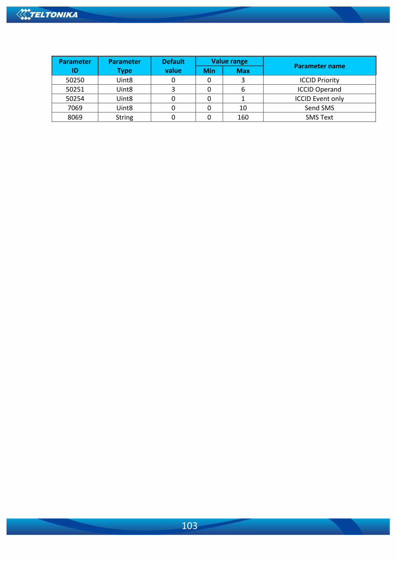
103
Parameter ID
Parameter Type
Default value
Value range Parameter name
Min Max
50250 Uint8 0 0 3 ICCID Priority 50251 Uint8 3 0 6 ICCID Operand 50254 Uint8 0 0 1 ICCID Event only 7069 Uint8 0 0 10 Send SMS 8069 String 0 0 160 SMS Text

104
8 DEBUG MODE
GH5200 device is able to provide its debug trace when it is connected to PC using the magnetic USB cable. This trace can be used to detect errors and provide debug information if the device functions not as expected. Required Terminal application can be downloaded using: http://avl1.teltonika.lt/Downloads/Software/Terminal.zip
When powered on GH5200 device is connected to PC, two ports are created: MTK USB Modem Port is used for modem trace; MTK USB Debug Port is used for Terminal log. If connected GH5200 device is not recognized by PC, please install the required drivers.
Following link can be used: http://avl1.teltonika.lt/Downloads/FMB1/ After selecting your port click Connect and then click on Start Log button. If the log is not
running, please send .log:1 command (see picture below).
Figure 38 Terminal.exe window

105
9 CHANGE LOG
Nr. Date Version Comments
1 2019-03-21 1.0 Preliminary release.