Embed Size (px)
Citation preview

CHIA
RAVA
LLIT
rasm
issi
onis
pa
“GIFLEX®” GE-T COUPLINGSwith FLEXIBLE SPIDER
TORSIONAL FLEXIBLE COUPLINGSPRECISE EXECUTION
INTRODUCTIONFlexible torsion couplings, which are connecting devices betweenrotating shafts, are designed to ensure shock-free torque transmis-sion and to compensate minor alignment deviations in operationbetween the shafts in industrial use.The GE-T range of flexible couplings ensures this level of perfor-mance and also provides excellent quality thanks to the machiningaccuracy and the choice of the materials used.The general level of reliability provided by the GE-T couplings isensured by a satisfactory useful working life of the couplings.
GENERALThe GE-T range of flexible couplings represents torsionally flexible,mechanical couplings capable of transmitting a twisting momentproportional to the flexible yield of the intermediate component.The couplings must also be capable of effectively absorbing possi-ble torsional vibrations due to the load or self-induced, to attenua-te impacts and torque peaks during the start-up phase and to com-pensate minor angular and parallel misalignments between theshafts, however ensuring an acceptable useful working life.These features and more in general the performance required from
the coupling depend almost exclusively on the quality of theintermediate component. The choice of the material used
to manufacture the coupling is therefore fundamen-tal. The curve that expresses the flexible charac-
teristic of the intermediate component musthave a progressive trend (yielding at low
torque values and remaining rigid athigher torque values) to ensure ope-
ration without jerks at start-upand with a limited torsional
yield at steady state condi-tions.
It is essential for the inter-mediate component tohave a certain flexiblehysteresis, proportionalto the required absor-bing effect that ensuresthe coupling can effi-
197
HUB B HUB A
CHIA
RAVA
LLIT
rasm
issi
onis
pa
“ G I F L E X ®” G E - T F L E X I B L E C O U P L I N G S
198
ciently absorb possible torsional oscillations. Furthermore, the use-ful working life of the coupling depends on the flexible yield of thematerial comprising the intermediary component. The physicalcharacteristics as described above are frequently in contrast witheach other and compared with other basic mechanical and tech-nological parameters. The performance of the intermediary com-ponent therefore cannot be adapted to the variety of operatingconditions when only one type of material is used and therefore thematerials adopted for the flexible ring gear must be differentiated.A selected thermoplastic elastomer is selected to meet medium levelneeds in the basic execution. This refers to an elastomer withmedium rigidity, characterised by an optimum internal dampeningeffect, resistant to ageing, to fatigue, to abrasion, as well ashydrolysis and to the principal chemical agents with special refe-rence to oils and ozone. Operating temperatures lying between–40°C and +125°C with brief peaks of up to 150°C are permittedin the case of couplings in the base execution. Alternative mixescapable of meeting every practical need have been designed andare available on request for use in extremely demanding operatingconditions, or for needs that exceed average requirements.
OPERATING AND ASSEMBLY CONDITIONSOperation of the flexible torsion couplings, such as the GE-T typeor similar couplings is characterised by a proportional featurebetween the twisting torque and the torsion angle and by the abi-lity to compensate limited angular and radial misalignments.Key features of equal importance, but which are more difficult tointerpret are represented by the absorbing factor and the naturalfrequency or resonance. To qualify its couplings, CHIARAVALLITrasmissioni spa declares permitted twisting torque values correla-ted to well defined torsion angle values, which has the limitingvalue of 5° corresponding to the maximum torque value. This pro-vides a valid guide for the progressive characteristic of the flexiblecurve. The maximum permitted values are shown in the case of theangular and radial misalignments, with the warning that theserefer to extreme values that cannot be added together (only angu-lar compensation or only radial compensation) and apply to"standard" operating conditions characterised by thefollowing: operating torque not exceeding the nomi-nal torque, a rotating speed of less than 1,450r.p.m and coupling temperature not excee-ding 40°C. The maximum rotating speedexpressed in r.p.m. that corresponds toa maximum peripheral speed of 30m/sec. is indicated for each cou-pling of the GE-T range. Thisspeed can be achieved with asufficient safety margincompared to the dangerof failure due to centrifu-gal force stress thanks tothe characteristics of thematerial used. Class G2.5 dynamic balancingin compliance with ISO

CHIA
RAVA
LLIT
rasm
issi
onis
pa
“ G I F L E X ®” G E - T F L E X I B L E C O U P L I N G S
199
1940 is recommended despite the fact that the half-couplings arefully machined on both external surfaces, if the actual operatingspeed exceeds 2.800 r.p.m.
COUPLING SELECTION AND SIZING CRITERIACouplings are sized on the basis of the physical laws of mecha-nics and the resistance of the materials and also complies with theprovisions established in the DIN 740 standards Sheet 2.The coupling is selected on the basis of the criteria, which establi-shes that the maximum permitted stress is never exceeded even inthe most demanding operating conditions. It follows that the nomi-nal torque declared for the coupling must be compared with areference torque that takes into account the overloads due to theway the load is exerted and the operating conditions. The refe-rence torque is obtained by multiplying the operating torque by aseries of multiplying factors depending on the nature of the loador on the ambient temperature conditions.
Symbols: TKN = coupling maximum torque (Nm)TK max = coupling maximum torque (Nm)TKw = torque with coupling inversion (Nm)TLN = driven side operating torque (Nm)TLs = driven side static torque (Nm)TAs = motor side static torque (Nm)Ts = plant static torque (Nm)PLn = driven side operating power (kW)nLn = driven side rotating speed (r.p.m.)St = temperature factor
SA = motor side impact factorSL = driven side impact factorSz = start-up factorMA = control side mass factor
ML = driven side mass factor
LOAD DUE TO NOMINAL TORQUEThe permitted nominal coupling torque TKN must
apply for any operating temperature valueequal to or greater than the driven side
operating torque TLN.
TLN = 9549 [Nm]
The following condition mustbe satisfied, where St
represents the temperatu-re factor, to take intoaccount overloads dueto the operating tem-perature for the cou-pling.TKN = > TLN * St
JLJA+JL
JAJA+JL
( PLn ) nLn

CHIA
RAVA
LLIT
rasm
issi
onis
pa
“ G I F L E X ®” G E - T F L E X I B L E C O U P L I N G S
START-UP LOAD
The drive motor delivers a drive torque during the start-up transientperiod, which is a multiple of the nominal torque and depends onthe way the masses are distributed. A similar situation occurs in thebraking phase therefore, these two phases are characterised bytorque impacts that have an intensity which depends on the distri-bution of the masses on the drive side MA and on the driven sideML, as well as the frequency of the number of start-ups on whichthe start-up factor Sz depends. The static torques for the drive sideand the driven side are expressed by the following relationships:
- drive side TS = TAS *MA *SA- driven side TS = TLS *MM *SL
MA and ML are assumed to be equal to 1, to a first approxima-tion, and if the distribution of the masses is unknown. The SA fac-tor can be assumed as being equal to the relationship between thestart-up torque and the nominal torque in the case of drives basedon an electric motor.
LOAD CAUSED BY TORQUE IMPACTS
The permitted nominal coupling torque TKN max must be equal toor greater than the start-up torque increased by the temperaturefactor and by St and by the start-up factor Sz for any operatingtemperature value.
TKN max > TS *St *Sz
Consult the CHIARAVALLI Trasmissioni Technical Department foroperating conditions that foresee periodic variations or torqueinversions, as well as alternate torsional stresses.
LOADCONDITION
SERVICE FACTORS
OPERATING CONDITIONSElectric motor Diesel engine
TYPE OF DRIVE
UNIFORM Regular operation without impacts or overloads 1.25 1.5LIGHT Regular operation with minor and infrequent impacts and overloads 1.50 2.0MEDIUM Irregular operation with medium overloads for a short duration and frequent but moderate impacts 2.0 2.5HEAVY Markedly irregular operation with very frequent impacts and overloads and of major intensity. 2.5 3.0
NAMEINDICATIVE VALUES FOR ADJUSTMENT FACTORS:
SYMBOL DEFINITION
Temperature St. St. 1 1.2 1.4 1.8Factor °C -30 +40 +80 +120
+30
Start-up Sz.Factor Start-up/hr. 100 200 400 800
Sz. 1 1.2 1.4 1.6
Impact SA/SL
Factor Minor start-up impactsMedium start-up impactsMajor start-up impacts
Number of start-ups per hour
SA/SL
1.51.82.2
200

CHIA
RAVA
LLIT
rasm
issi
onis
pa
“ G I F L E X ®” G E - T F L E X I B L E C O U P L I N G S
201
TECHNICAL DATA
94 10 20 2.6 0.68 0.57 0.44 0.28 1.2 0.2 1.2°
94 35 70 9 2.19 1.82 1.40 0.90 1.4 0.2 0.9°
94 95 190 25 5.20 4.31 3.32 2.12 1.5 0.25 0.9°
94 190 380 49 10.00 8.30 6.39 4.08 1.8 0.28 1.0°
94 265 530 69 17.00 14.11 10.86 6.94 2.0 0.32 1.0°
94 310 620 81 20.00 16.59 12.77 8.16 2.1 0.36 1.1°
94 410 820 105 21.99 18.25 14.05 8.98 2.2 0.38 1.1°
94 625 1250 163 28.20 23.39 18.01 11.51 2.6 0.42 1.2°
94 975 1950 254 67.99 56.41 43.44 27.75 3.0 0.48 1.2°
94 2400 4800 624 110.0 91.26 70.27 44.89 3.4 0.50 1.2°
TYPEMaximum
misalignmentTorsional Rigidity
(kNm/rad)Twisting Moment
(Nm)Toothed
StarMax. R.p.m.
TorsionAngle
Radialαα
mmb
m m
1.0TKN
0.75TKN
TKNNorm.HardnessTKN TKmaxn.
(min-1)MAX
TKmax
TKW with
Invers.0.5TKN
0.25TKN
Axial
displa
cem
ent
Angular
γγ°
3.0° 5°
14000
10600
8500
7100
6000
5600
4750
4250
3550
2800
19/24
24/32
28/38
38/45
42/55
48/60
55/70
65/75
75/90
90/100
94 SHORE A BLACK SPIDER THERMOPLASTIC RUBBER

CHIA
RAVA
LLI T
rasm
issi
oni s
pa
“ G I F L E X ®” G E - T F L E X I B L E C O U P L I N G S
TECHNICAL DATA
96 17 34 4.4 1.09 0.90 0.68 0.42 1.2 0.2 1.2°
96 60 120 16 3.70 3.04 2.31 1.44 1.4 0.2 0.9°
96 160 320 42 9.5 7.80 5.92 3.68 1.5 0.25 0.9°
96 325 650 85 29.0 23.8 18.06 11.24 1.8 0.28 1.0°
96 450 900 117 40.5 33.24 25.21 15.70 2.0 0.32 1.0°
96 525 1050 137 48.56 39.86 30.23 18.82 2.1 0.36 1.1°
96 625 1250 163 52.78 43.32 32.86 20.46 2.2 0.38 1.1°
95 640 1280 166 57.5 47.19 35.80 22.29 2.6 0.42 1.2°
95 1465 2930 381 150.0 123.12 93.39 58.14 3.0 0.48 1.2°
95 3600 7200 936 250.0 205.19 155.65 96.90 3.4 0.50 1.2°
3.0° 5°
14000
10600
8500
7100
6000
5600
4750
4250
3550
2800
19/24
24/32
28/38
38/45
42/55
48/60
55/70
65/75
75/90
90/100
96 SHORE A RED SPIDER THERMOPLASTIC RUBBER96 SHORE A YELLOW SPIDER POLYURETHANE
202
TYPEMaximum
misalignmentTorsional Rigidity
(kNm/rad)Twisting Moment
(Nm)Toothed
StarMax. R.p.m.
TorsionAngle
Radialαα
mmb
mm
1.0TKN
0.75TKN
TKNNorm.HardnessTKN TKmaxn.
(min-1)MAX
TKmax
TKWwith
Inversion
0.5TKN
0.25TKN
Axial
displa
cem
ent
Angular
γγ°

CHIA
RAVA
LLI T
rasm
issi
oni s
pa
“ G I F L E X ®” G E - T F L E X I B L E C O U P L I N G S
GE-T COUPLINGS designed for CEI standardised motors
GE-TTYPE FsP
(kW)T
(Nm)GE-TTYPE FsP
(kW)T
(Nm)GE-TTYPE FsP
(kW)T
(Nm)GE-TTYPE FsP
(kW)T
(Nm)
0.75 2.4 8.0 0.55 3.6 5.4 0.37 3.6 5.1 0.18 2.3 8.0
80 19/24 19/24 19x40
1.1 3.619/24
5.4 0.75 4.919/24
3.9 0.55 5.4 3.4 0.25 3.2 5.7
90 S 1.5 4.9 4.0 1.1 7.6 2.7 0.75 7.3 2.5 0.37 4.8 3.8 24x50
90 L 2.2 7.2 2.7 1.5 9.8 2.0 1.1 10.8 5.8 0.55 7.2 2.5
2.2 14.4 4.7 0.75 9.8 6.4
100 L 3 9.8 7.1 1.5 14.7 4.7
24/323 19.6
24/323.5
24/321.1 14.4
24/324.4 28x60
112 M 4 13.1 5.4 4 26.2 2.6 2.2 21.6 3.2 1.5 19.7 3.3
5.5 18.0 10.6
132 S 5.5 36 5.3 3 29.5 6.3 2.2 28.8 6.6
7.5 24.628/38
7.628/38 28/38 28/38
38x80
4 39 4.8
132 M 7.5 49 3.9 3 39 4.8
5.5 54 3.5
11 36 10.6 4 52 7.0
160 M 11 72 5.3 7.5 73 5.1
15 4938/45
7.838/45 38/45
5.5 7238/45
5.1 42x110
160 L 18.5 60 6.3 15 98 3.9 11 108 3.5 7.5 98 3.8
180 M 22 72 7.5 18.5 121 4.4 48x110
180 L 22 144 3.7 15 147 3.6 11 144 3.7
30 98 5.5 42/55 18.5 182 42/55 2.9 42/55
200 L 30 196 2.7 15 197 2.7 55x110
37 121 42/55 4.4 22 216 2.5
225 S 37 24248/60
2.648/60
18.5 24248/60
2.5
225 M 45 147 3.7 45 295 2.1 30 295 2.1 22 288 2.1 55x110 60x140
250 M 55 180 48/60 3.5 55 360 55/70 2.1 37 364 55/70 2.1 30 394 65 2.2 60x140 65x140
280 S 75 246 3.1 75 49275
4.0 45 44275
4.4 37 48575
4.0 75x140
280 M 90 295 55/70 2.6 90 590 3.4 55 541 3.6 45 591 3.3
315 S 110 360 2.1 110 72175/90
2.8 75 73875/90
2.7 55 722 75/90 2.7
315 M 132 433 4.6 132 866 2.3 90 885 2.3 65x140 80x170
160 525 3.8 160 1030 4.7 110 1070 4.5 90 1170 4.1
315 L 75/90 90 90 90
200 65675/90
3.0 200 1290 3.7 132 1280 3.8 110 1420 3.4
250 820 2.4 250 1610 3.0 160 1550 90/100 3.1 132 1710 70/100 2.8
355 L 90/100 2.4 200 1930 2.5 160 2070 3.2 75x140 95x170
315 1010 4.8 315 2020 250 2420 100 2.7 200 2580 100 2.6
355 1140 4.2 355 2280 2.9
400 L 90/100 3.8 100 315 3040 80x170 100x210
400 1280 400 2560 2.6
203
ELECTRICMOTOR
TYPE
Motor poweroutput at 50 Hz.n = 3000 min.
COUPLINGMotor power
output at 50 Hz.n = 1500 min.
COUPLINGMotor power
output at 50 Hz.n = 1000 min.
COUPLINGMotor power
output at 50 Hz.n = 750 min.
Shaftend
dxl (mm)
3000<1500
COUPLING
CHIA
RAVA
LLI T
rasm
issi
oni s
pa
204
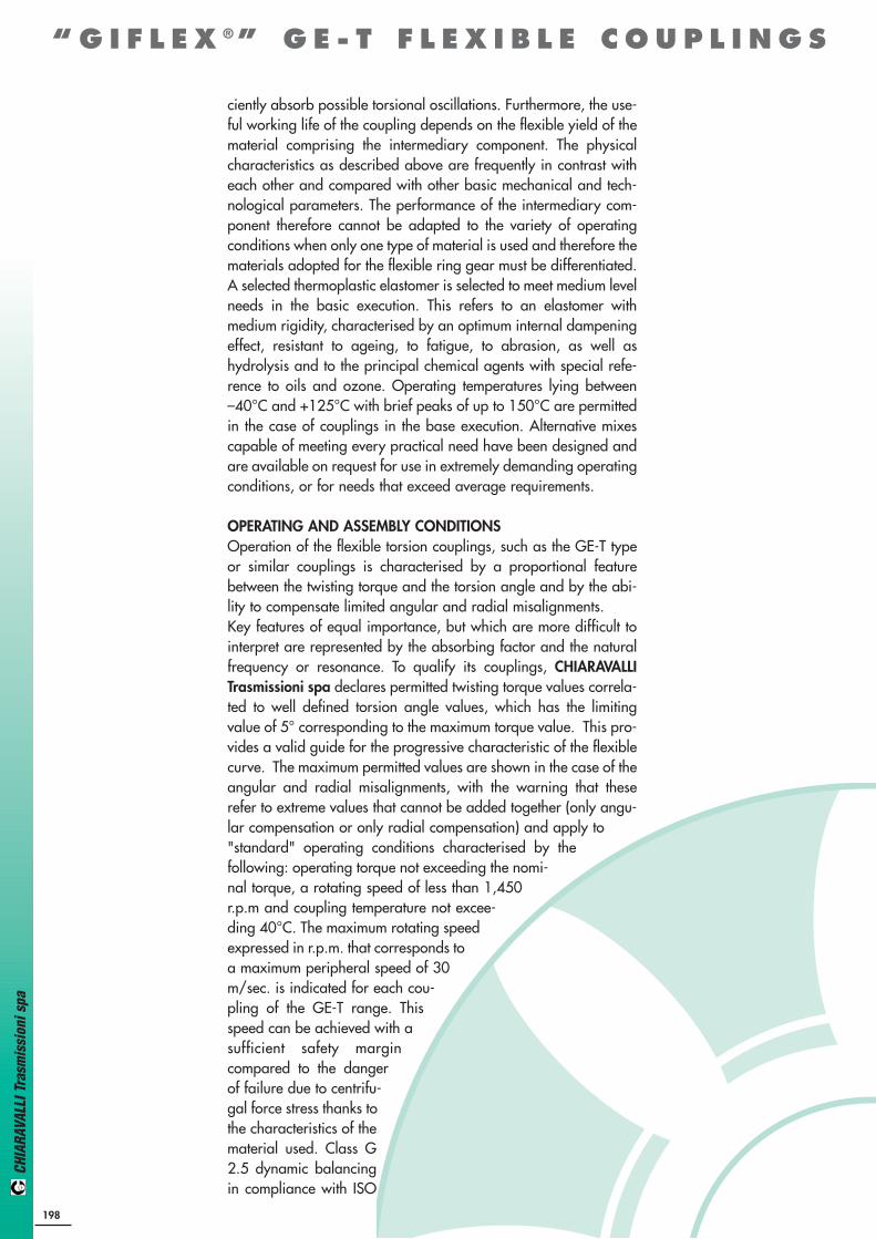
“ G I F L E X ® ” G E - T P R E C I S I O N R A N G E
Material: G25 CAST IRON * STEEL
COUPLINGTYPE
Mass Kg.Measurements in mm.
Normal range
WITHOUTBORE
Finishedbore d
HubB
HubA
FlexibleComponentC D E F M M1 N R S Ld
max.d1
max.A B
JKg.cm2
HubsA+B
(3)
(1)
(2)
DIMENSIONS
(1) Assembly distances(2) Coupling inertia moment with hubs A-B and max. bore Ø(3) On request: Finished bore in compliance with ISO standards, H7 tolerance, keyway DIN 6885, sheet 1, JS9 tolerance.
Dowel bore.
The characteristic size of the coupling is defined by the maximum bore diameter.
Code interpretationExample:GE-T 19A - 24B = with hub A +hub BGE-T 19A - 19A = with 2 hubs AGE-T 24B - 24B = with 2 hubs B
GE-T 19A-24B* - - 19 24 25 40 16 18 30 40 12 19 2 66 0.004 0.18 0.25 0.8
GE-T 24A-32B - - 24 32 30 55 18 27 40 55 14 24 2 78 0.014 0.36 0.55 3
GE-T 28A-38B - - 28 38 35 65 20 30 48 65 15 27.5 2.5 90 0.025 0.60 0.85 7
GE-T 38A-45B - - 38 45 45 80 24 38 66 78 18 36.5 3 114 0.042 1.35 1.65 20
GE-T 42A-55B - - 42 55 50 95 26 46 75 94 20 40 3 126 0.066 2.00 2.30 50
GE-T 48A-60B - - 48 60 56 105 28 51 85 104 21 45 3.5 140 0.088 2.75 3.10 80
GE-T 55A-70B - - 55 70 65 120 30 60 98 118 22 52 4 160 0.116 4.20 4.50 160
GE-T 65A-75B - - 65 75 75 135 35 68 115 134 26 61 4.5 185 0.172 6.50 6.80 310
GE-T 75A-90B - - 75 90 85 160 40 60 135 158 30 69 5 210 0.325 10.00 10.80 680
GE-T 90A-100B 38 38 90 100 100 200 45 100 160 180 34 81 5.5 245 0.440 14.00 15.80 1590
MEASUREMENTS - WEIGHTS

CHIA
RAVA
LLI T
rasm
issi
oni s
pa
“ G I F L E X ® ” G E - T P R E C I S I O N R A N G E
COUPLINGTYPE
Mass Kg.Measurements in mm.
Normal range
Finishedbore dTaper
LockBush Hubs B1
Max.Bore
FlexibleComponentC D E F M N S L Rd
min.d
max.
JKg. cm2
HubsB1
(1)
(2)
GE-T28-38 B1-TL 1108 14 25 23 65 20 30 65 15 2.5 66 0.025 0.50 7
GE-T38-45 B1-TL 1108 14 25 23 80 24 38 78 18 3 70 15 0.042 0.88 26
GE-T42-55 B1-TL 1610 14 42 26 95 26 46 94 20 3 78 16 0.066 1.40 36
GE-T48-60 B1-TL 1615 19 40 39 105 28 51 104 21 3.5 106 28 0.088 2.33 78
GE-T55-70 B1-TL 2012 19 50 33 120 30 60 118 22 4 96 20 0.116 2.42 120
GE-T75-90 B1-TL 2517 19 65 52 160 40 80 158 30 5 144 36 0.325 6.80 630
(1) Assembly distances(2) Coupling inertia moment with hubs I and E max. bore
Code interpretationExample:GE-T 28I - 38E = with hub I + hub EGE-T 28I - 28I = with 2 hubs IGE-T 38E - 38E = with 2 hubs E
EXECUTION WITH TAPER-LOCK® BUSH
DIMENSIONS
Material: G25 CAST IRON
MEASUREMENTS - WEIGHTS
205
HUB I HUB E

CHIA
RAVA
LLI T
rasm
issi
oni s
pa
ALUMINIUM ALLOY EXECUTION
Material: ALUMINIUM ALLOY
COUPLINGTYPE
Mass Kg.Measurements in mm.
Normal range
WITHOUTBORE
Finishedbore d
HubB
HubA
FlexibleComponentC D E F M M1 N R S Ld
max.d1
max.A B
JKg.cm2
HubsA+B
(3)
(1)
(2)
GE-T 19A-24B/AL _ 10 19 24 25 40 16 18 30 40 12 19 2 66 0.005 0.07 0.08 0.4
GE-T 24A-32B/AL 8 14 24 32 30 55 18 27 40 55 14 24 2 78 0.014 0.13 0.18 1.0
GE-T 28A-38B/AL 10 16 28 38 35 65 20 30 48 65 15 27.5 2.5 90 0.025 0.22 0.30 3.0
GE-T 38A-45B/AL 12 20 38 45 45 80 24 38 66 78 18 36.5 3 114 0.042 0.48 0.55 8.0
DIMENSIONS
(1) Assembly distances(2) Coupling inertia moment with hubs A and B and max. bore Ø(3) On request: Finished bore in compliance with ISO standards, H7 tolerance, keyway DIN 6885, sheet 1, JS9 tolerance.
Dowel bore.N.B.: use of a polyurethane elastomer is recommended
Code interpretationExample:GE-T 19A - 24B/AL = with hub A + hub BGE-T 19A - 19A/AL = with 2 hubs AGE-T 24B - 24B/AL = with 2 hubs B
MEASUREMENTS - WEIGHTS
206
GE-T 19A-24B/AL _ 10 19 24 25 40 16 18 30 40 12 19 2 66 0.005 0.07 0.08 0.4
GE-T 24A-32B/AL 8 14 24 32 30 55 18 27 40 55 14 24 2 78 0.014 0.13 0.18 1.0
GE-T 28A-38B/AL 10 16 28 38 35 65 20 30 48 65 15 27.5 2.5 90 0.025 0.22 0.30 3.0
GE-T 38A-45B/AL 12 20 38 45 45 80 24 38 66 78 18 36.5 3 114 0.042 0.48 0.55 8.0
“ G I F L E X ® ” G E - T P R E C I S I O N R A N G E

CHIA
RAVA
LLI T
rasm
issi
oni s
pa
“GIFLEX®” GE-T SG BACKLASH-FREE TORSIONAL COUPLING
INTRODUCTIONThe aluminium flexible couplings GE-T SG are made of three pre-ten-sioned elements in backlash-free execution.They are meant for the coupling mounting and they are designed to fit
low torque working units and industrial processing, wherethey must satisfy certain requirements.
Thanks to their limited dimensions and their easymounting, they can operate in little space and anyproject can take big advantages of it.
FEATURESThe buckle tightening guarantees a quick and sure fixing without exten-sion between shaft and hub. It is however important to keep the screwtightening torque (MS) shown in the table.Besides testing the size of the coupling given in the table, it is sugge-sted to test the maximum torque of buckle to diameter (F). The elastomeric element, that has a star shape, is set into the hubs' hol-low seats with a light pre-tensioning , ensuring the needed transmissiontorque backlash-free execution.
ElastomericelementhardnessShore A
N. maxspeed
revolutionV=30m/s Tksg Tkn Tk mx Torsion statica
Nm/radTorsion dinam.
Nm/rad Hub Star
TORQUE (Nm) STIFFNESS WEIGHT Mass inertiamoment
Kgm2 x 10–6
COUPLINGGE-T SG radial N/mm
9
14
19/24
24/28
28/38
38/45
80
92
98
80
92
98
80
92
98
80
92
98
80
92
98
80
92
98
28000
19000
14000
10600
8500
7100
0,45
1,0
2,5
1,8
3,0
5,0
4,0
7,5
12,5
4,9
10,0
17,0
17,0
35,0
60,0
46,0
95,0
160,0
94,0
190,0
325,0
3,6
6,0
10,0
8,0
15,0
25,0
9,8
20,0
34,0
34,0
70,0
120,0
92,0
190,0
320,0
188,0
380,0
650,0
17,02
31,5
51,5
60,2
114,6
172,0
343,8
573,0
859,0
1432,0
2063,0
2292,0
3438,0
4589,0
7160,0
52
95
150
180
344
513
1030
1720
2580
4296
6189
6879
10315
13752
21485
125
262
518
153
336
604
582
1120
2010
1480
2560
1780
3200
2350
4400
0,009
0,020
0,066
0,132
0,253
0,455
0,002
0,005
0,007
0,018
0,029
0,049
0,57
3,25
21,90
58,30
216,80
445,20
TECHNICAL DATA (Polyurethane elastomeric element in blu colour 80 shore A - in yellow colour 92 shore A - in red colour 98 shore A).
207
N.B. FOR EXTERNAL SPEED MORE THAN V=30m/s DYNAMIC BALANCING IS NEEDED.

CHIA
RAVA
LLI T
rasm
issi
oni s
pa
208
“ G I F L E X ® ” G E - T S G
COUPLINGTYPE
DIMENSIONS: EXECUTION A IN ALUMINIUM ALLOY WITH PLAIN HUB
F min. F max D G L C E N s
9
14
19/24
4
4
8
10
16
20
20
30
40
7,2
10,5
18
30
35
66
10
11
25
10
13
16
8
10
12
1,0
1,5
2,0
COUPLINGTYPE
DIMENSIONS: EXECUTION B IN ALUMINIUM ALLOY WITH PLAIN HUB
F min. F max D G L C E N s
24/28
28/38
38/45
12
18
18
28
35
45
55
65
80
27
30
38
78
90
114
30
35
45
18
20
24
14
20
18
2,0
2,5
3,0

CHIA
RAVA
LLI T
rasm
issi
oni s
pa
“ G I F L E X ® ” G E - T S G
COUPLINGTYPE
F min.
24/28
28/38
38/45
DIMENSIONS: EXECUTION D IN ALUMINIUM ALLOY WITH DOUBLE SPLIT
Execution F max D G L C E N s f Ms screws (Nm) t
12
18
18
B
B
B
28
35
45
55
65
80
27
30
38
78
90
114
30
35
45
18
20
24
14
15
18
M6
M8
M8
11,0
25,0
25,0
14
15
20
2,0
2,5
3,0
COUPLINGTYPE
24/28
28/38
38/45
PRODUCED DIAMETER OF BORES (F)
5 6 8 10 12 14 15 16 18 19 20 22 24 25 28 30 32 35 38 40
25 26 27 27,5 28
60
69
28,5
61
70
29
62
71
30
63
73
31
65
74
32
66
78
33
69
78
71
80
73
81
75
84 87 88
ALLOWED TORQUE (Nm)
COUPLINGTYPE
F min.
9
14
19/24
DIMENSION: EXECUTION C IN ALUMINIUM ALLOY WITH SIMPLE SPLIT
Execution F max D G L C E N s f Ms screws (Nm) t
4
4
8
A
A
A
10
16
20
20
30
40
7,2
10,5
18
30
35
66
10
11
25
10
13
16
8
10
12
M2,5
M3
M6
0,75
1,40
11,0
5
5
12
1,0
1,5
2,0
COUPLINGTYPE
9
14
19/24
PRODUCED DIAMETER OF BORES (F)
5 6 8 10 12 14 15 16 18 19 20 22 24 25 28 30 32 35 38 40
1,55
3,32
1,63
3,43
1,79
3,67
18
1,94
3,91
19
4,14
20
4,38
21
4,5
21,5
4,6
22 22,5 23 24
ALLOWED TORQUE (Nm)
209