Embed Size (px)
Citation preview
AUTHOR: SBOGAERT PAGE: 1/115
DATE: 2019-10-25 VERSION: 1
TITLE: MRI USER MANUAL SIEMENS PRISMA
GIfMI MRI user manual SIEMENS PRISMA Stephanie Bogaert, MSc
Pieter Vandemaele, MSc
Pim Pullens, PhD
© Ghent Institute for functional and Metabolic Imaging
April 2019
OVERVIEW I. Introduction ....................................................................................................................................................... 5
Note to the reader ................................................................................................................................................. 5
Contact ................................................................................................................................................................... 5
Important phone numbers..................................................................................................................................... 5
II. GIfMI scanning policy – MRI safety .................................................................................................................... 6
Policy regarding personnel - requirements ........................................................................................................... 6
Access conditions ................................................................................................................................................... 6
Policy regarding pregnancy .................................................................................................................................... 6
Policy regarding obese participants ....................................................................................................................... 7
Policy regarding children........................................................................................................................................ 7
Policy regarding patient populations ..................................................................................................................... 7
III. Emergency procedure .................................................................................................................................... 8
Main hazards .......................................................................................................................................................... 8
Reporting of safety incidents or near-incidents .................................................................................................... 8
Medical crash cart, medical gases and AED ........................................................................................................... 8
Use of the MR compatible stretcher ...................................................................................................................... 8
Performing an emergency magnet quench: Magnet Stop switch ......................................................................... 9
Situations requiring a Magnet Stop: .................................................................................................................. 9
Quench procedure ............................................................................................................................................. 9
Performing a table stop ....................................................................................................................................... 10
Table stop procedure ....................................................................................................................................... 10
Fire safety ............................................................................................................................................................. 12
IV. THE GIFMI FACILITY ...................................................................................................................................... 13
MRI Control room ................................................................................................................................................ 13
MRI scanner room ................................................................................................................................................ 14
Equipment in the MRI scanner room ............................................................................................................... 15
Version 1 2019-10-25 2
Preparation room ................................................................................................................................................. 16
Meeting room Hippocampus ............................................................................................................................... 17
V. GETTING STARTED: MRI USER MANUAL ......................................................................................................... 18
a. Switching on/off the scanner and satellite console ......................................................................................... 18
Switching the MRI system ON .............................................................................................................................. 18
Switching the MRI system OFF ............................................................................................................................. 20
Switching the satellite console (MDDW-DWG) ON ............................................................................................. 23
Switching the satellite console OFF ..................................................................................................................... 24
b. Communication between participant and researcher ..................................................................................... 24
Inside the console room: the intercom ................................................................................................................ 24
Inside the scanner room: squeeze ball (participant’s alarm) and Siemens ear phones ...................................... 25
Video camera and display .................................................................................................................................... 26
c. Table operation ................................................................................................................................................ 26
Control panel and display .................................................................................................................................... 26
How to use the control panel to move the table in the bore .............................................................................. 27
How to use the control panel to move the table out of the bore ....................................................................... 29
How to use the display ......................................................................................................................................... 31
How to use the jog wheel .................................................................................................................................... 32
d. Understanding the SIEMENS interface ............................................................................................................ 32
The keyboard ....................................................................................................................................................... 32
Interface ............................................................................................................................................................... 33
Upper toolbar ................................................................................................................................................... 33
Lateral toolbar .................................................................................................................................................. 34
Bottom toolbar ................................................................................................................................................. 36
e. Participant preparation .................................................................................................................................... 37
Informed consent ................................................................................................................................................. 37
MR screening and demetallization ...................................................................................................................... 37
f. Participant positioning (for standard brain imaging) ....................................................................................... 37
Parts of the 64 channel head coil ......................................................................................................................... 37
Installing the 64 channel head coil (head support).............................................................................................. 38
Positioning a participant for a typical brain scan ................................................................................................. 39
Landmarking a participant for a typical brain scan .............................................................................................. 40
How to get the participant out of the 64 channel head coil: ............................................................................... 41
g. Anonymous pre-registration of the participant (mandatory) .......................................................................... 42
How do I create a QP-number in RIS? .................................................................................................................. 43
How do I create an MRI application form? .......................................................................................................... 46
How do I retrieve the preregistered RIS form on the scanner? ........................................................................... 49
Version 1 2019-10-25 3
h. Start to acquire data ........................................................................................................................................ 53
How do I select my protocol? .............................................................................................................................. 53
How do I conduct a typical brain scan? ............................................................................................................... 54
Localizer ........................................................................................................................................................... 54
Sagittal 3D-T1 structural imaging ..................................................................................................................... 56
MPR (Multiplanar Reconstruction) .................................................................................................................. 60
Axial EPI functional imaging (gre field map, ep2d bold fMRI) ......................................................................... 63
Axial EPI functional imaging (ep2d_DTI) .......................................................................................................... 65
Axial EPI functional imaging (ep2d_DTI_PA) .................................................................................................... 66
Multiplying sequences ......................................................................................................................................... 67
Copying the slice information of sequences ........................................................................................................ 67
VI. DATA TRANSFER ........................................................................................................................................... 69
How do I anonymize data?................................................................................................................................... 69
How do I send my (anonymized) data to a workstation / PACS ? ....................................................................... 70
How do I export my (anonymized) data to an external medium (USB, HDD, …)? ............................................... 71
How do I import data from a HDD? ..................................................................................................................... 74
How do I import data from a cd/dvd? ................................................................................................................. 75
VII. Protocol transfer .......................................................................................................................................... 77
How do I import a protocol on the scanner? ....................................................................................................... 79
How do I export a protocol? ................................................................................................................................ 81
How do I make print screens of my protocol on the scanner? ............................................................................ 81
How do I export or print the parameters of my protocol as a pdf-file? .............................................................. 83
VIII. FAQ ............................................................................................................................................................... 85
Why does the scanner instruct me that the participant bed might move when I start the first scan in my session
(usually a localizer)? ............................................................................................................................................. 85
Why is the head of the participant upside down? ............................................................................................... 85
How can I check whether the head coil is recognized by the scanner? .............................................................. 87
How long will the scan take (time of acquisition, TA)? ........................................................................................ 88
How do I copy sequences/a protocol from the browser? ................................................................................... 89
How do I multiply sequences? ............................................................................................................................. 90
How do I check the positioning of the FOV when that sequence is already running or even ready. .................. 90
How do I check the parameters when a sequence is already running or even ready. ........................................ 90
How do I change the parameters when the sequence is already running or even ready. .................................. 90
How do I build my own protocol? ........................................................................................................................ 91
Why do I get the popup ‘Invalid coil selection’. What to do? .............................................................................. 93
Why is GRAPPA switched off when opening a sequence?................................................................................... 94
Why do I get a SAR warning? ............................................................................................................................... 95
Version 1 2019-10-25 4
Can I add 5 kg to the participant’s weight to overcome the scanner’s SAR limit? .............................................. 95
Why does the scanner warn for nerve stimulation?............................................................................................ 95
I accidentally moved the tabletop to the home position but I want to continue scanning? .............................. 95
How do I apply changes to my protocol? ............................................................................................................. 95
I want more volumes in my EPI time series. How do I do that? .......................................................................... 96
How much participant movement is too much? ................................................................................................. 97
What to do with incidental findings? ................................................................................................................... 98
IX. Problem / Error solving ................................................................................................................................ 99
The scanner doesn’t seem to be working properly. How can I tell what is wrong? ............................................ 99
The scanner doesn’t seem to be working properly. What can I do (in general)? .............................................. 100
Performing a routine scanner reboot or shutdown. ...................................................................................... 100
Error in the Host tab....................................................................................................................................... 101
Error in the Image Reconstr System tab ........................................................................................................ 102
Error in the Periphery tab .............................................................................................................................. 103
How to make a system log file after a serious error ...................................................................................... 104
How to check the Magnet/cooling status of the scanner? ............................................................................ 106
Most common problems .................................................................................................................................... 107
There is no chirping from the cooling system when I enter the scanner room. ............................................ 107
Upon arrival, there is an audible alarm coming from the alarm box ............................................................. 108
Helium is too low ........................................................................................................................................... 108
Popups ............................................................................................................................................................ 109
Red marks in the MR system manager – tab MR scanner ............................................................................. 110
Patient Table warning: STOP button pressed by user ................................................................................... 112
My measurement won’t start. ....................................................................................................................... 112
The scanner blocks after starting the ‘Neuro3D’ application. ....................................................................... 113
The scanner table freezes .............................................................................................................................. 113
Image artifacts (spikes, lines, graininess, …) .................................................................................................. 114
The pie chart is colored in red........................................................................................................................ 114
Problem: the wall lighting in the scanner room is off – what to do? ................................................................ 114
X. Contact ........................................................................................................................................................... 115
Reporting incidents ............................................................................................................................................ 115
Who to contact? ................................................................................................................................................. 115
Version 1 2019-10-25 5
I. Introduction The Siemens MAGNETOM Prisma is a 3.0 Tesla imaging device that uses magnetic resonance. It generates cross-
sectional images in any orientation, representing the internal structure of the participant’s body/head. MR images
indicate the spatial distribution of hydrogen nuclei (protons) in the tissue. For an introduction into MR imaging,
we recommend the book “MRI from Picture to Proton” 3rd ed. by Donald W McRobbie et al.
For the novice user, using the scanner may be a bit overwhelming. Don’t worry, you can’t damage the system
when scanning, because there are many safety features built in to protect the system and the subject you are
scanning. Always respect the MRI safety rules!
Secondly, keep in mind that this is a multi-million euro device, and all the components of the scanner are very
expensive (a head coil can cost up to €100k to replace). Treat the scanner and its components with care!
Note to the reader This manual was created with great care. It might occur however, that some screenshots do not fully match the
view on the scanner console. The information in the screenshot is still valid.
Contact GIfMI Campus UZ Gent C.Heymanslaan 10 Ingang 55 9000 Gent
Important phone numbers Add (09 33) when calling from outside the hospital.
MR scanner room 21240 Emergency cardiac arrest 81 Emergency fire 88 Lab manager 24820 Research assistant 25062 MR Physicist 28975 Radiologist on duty 24158 Clinical MRI 24761
HAPPY SCANNING!
no this is not an MR image..
Version 1 2019-10-25 6
II. GIfMI scanning policy – MRI safety
Policy regarding personnel - requirements - Study Ethical Committee Approval
- GIfMI Science Board (GSB) Approval
- MRI Safety training GIfMI research assistant/site manager
- MRI Operational training GIfMI research assistant or an experienced colleague
- Physiologic monitoring training GIfMI site manager (only if applicable)
- GSB number GIfMI site manager
- Access key and badge GIfMI research assistant
- Personal MRI safety screening Fulfill the document GIfMI_Pre Scan_researcher
Access conditions Used properly, the magnetic resonance imaging equipment contained within the MRI lab is safe, however it poses
serious risks to the unwary. Therefor
Users of the lab should be familiar with this manual and with the procedures for protecting others from
hazards.
The MR system may be operated only by personnel who has completed the GIfMI safety training;
observers who have not been safety trained are not permitted to the MRI suite without notification to
the MRI site manager and MRI research assistant.
Ensure that unauthorized persons (e.g., electricians or cleaning personnel) do not enter the examination
room unless accompanied by the MRI site manager or MRI research assistant.
In emergency situations, you must ensure that no one without proper training enters the scanner room.
Resist the temptation to show visitors the scanner ‘up close’ as this introduces unnecessary risk of
exposing people to potential hazards. Tours that would involve having non-safety trained personnel in
the scanner room, must be authorized in advance by the GIfMI site manager or research assistant.
!! The MR scanner room door should be closed at all times: when not scanning, keep the door closed to
prevent anyone from entering by ignorance. When you are at work in the scanner room, close the door
behind your back to prevent anyone from coming in while you are occupied with the participant. Use
the scanner room door as a barrier!
Policy regarding pregnancy Although there is no evidence that participation in an MR study by a pregnant woman would be harmful to her
fetus, MRI studies for research purposes are not allowed during pregnancy.
GIfMI policy:
Participants - Pregnant women may not undergo MR studies unless the study itself is specifically designed
to investigate pregnancy with Ethics Committee approval.
Mentors - Mentors (including a pregnant parent or spouse of a research subject) who are pregnant are
not allowed into the scanner room at any time.
Personnel - Pregnant personnel is not allowed in the scanner room at any time during the first trimester.
During the second and third trimester they are not to remain in the scanner room while the scanner is in
operation.
Version 1 2019-10-25 7
It is not laboratory policy to require pregnancy testing for research subjects.
Policy regarding obese participants The Prisma 3.0 Tesla scanner bed is designed to support weights up to 200 kilograms. Subjects weighing more
than 200 kilograms should not be scanned. To avoid burns or peripheral nerve stimulation, a minimum distance
of 5 mm should be maintained between the subject’s body and the wall of the scanner tunnel. MR pads or cotton
sheets available in the MR scan rooms can be used to assure this distance is maintained.
Policy regarding children Children may only enter the scan room as participants in an Ethics Committee approved research study of
children. Children not involved in the research study (e.g, the child or sibling of a research subject) may not enter
the scan room and may only be present in the control room if under direct adult supervision. Equipment room
doors must be kept closed whenever children are present. All safety precautions applicable to adult subjects are
applicable and if anything, more important in children. Careful metal screening, accurate entry of age, sex and
weight are important steps in minimizing risks to this population.
Policy regarding patient populations Located on the same campus of Ghent University Hospital, the hospital provides emergency services for patients
undergoing studies in GIfMI MRI suite. To reduce the likelihood of adverse outcome in the event of a medical
emergency, the following policies apply to all patient studies:
All hospital patients undergoing MRI studies must be accompanied by a physician or nurse familiar with
the patient’s medical condition. The only exception to this policy pertains to patients who are admitted
to the CRC (clinical research center) as a result of participation in a research study and who would
otherwise not be hospitalized.
Solo scanning of patients at significant risk of a life threatening medical event on nights or weekends is
not acceptable.
Careful attention must be given to metal screening of patients with impaired cognitive abilities.
Scanning of patient is only allowed in the presence of a recognized medical radiographer. Ask the GIfMI
research assistant for more information.

Version 1 2019-10-25 8
III. Emergency procedure
Main hazards The main hazards in the lab are:
The projectile effect when heavy, sharp or dangerous objects are hurled into the instrument; even
seemingly innocuous objects can be lethal. Many objects in the control room and equipment room are
not MR compatible. Except for the stretcher (labeled ‘MR safe’) you must never move any object from
this room into the MR scanner room. Always ask the permission of the GIfMI research assistant/site
manager before you bring new equipment into the scanner room.
Under no circumstances should participants with active implants (implants that are electrically,
magnetically, or mechanically active such as cardiac pacemakers and implanted drug pumps) or
participants with intracranial aneurysm clips enter the MRI suite; correct functioning of the implants may
be affected by the magnetic and electromagnetic fields and therefor these participants have to be
excluded.
Suffocation: in extreme cases, the imaging magnet may release large volumes of helium gas that can
rapidly force all air out of the scan room. Normally, the helium gas would be vented through the roof.
However, there is a small but significant risk that the venting system could fail.
Inform participants about the noise generated during the examination. Use hearing protection
(combination of headset and ear plugs -35dB is mandatory) to protect participants against injury. Ensure
that personnel in the examination room wears hearing protection during the examination.
Reporting of safety incidents or near-incidents All incidents or near-incidents must be reported to the GIfMI site manager/research assistant as soon as possible
and no more than 24 hours after the incident. Contact information is available at the beginning of this manual.
Medical crash cart, medical gases and AED A medical crash cart is kept locked in the equipment room. An Automated External Defibrillator (AED) is located
above the medical crash cart. The crash cart, associated equipment and AED are not MR safe and should NEVER
be brought into an MR scan room. A subject in need of resuscitation must be removed from the scan room using
the MR compatible stretcher before crash cart equipment and supplies can be safely used. The scanner room is
equipped with compressed air and suction. An oxygen tank is located on the crash cart and tubing is located in
the crash cart drawers. The oxygen tank is NOT MR compatible. The scanner room is equipped with pulse
monitoring.
Use of the MR compatible stretcher The stretcher is used to transport immobile participants directly from and to the participant table in the scanner
room. The stretcher is labeled ‘MR safe’.
Free the stretcher of magnetic objects (oxygen bottles, scissors, …) before bringing it into the scanner
room. Leave the slide board on top.
Move the scanner bed out of the gantry. Adjust its height to match the stretcher.
Position the side of the stretcher next to the scanner bed. Lock all four wheels of the stretcher!
Version 1 2019-10-25 9
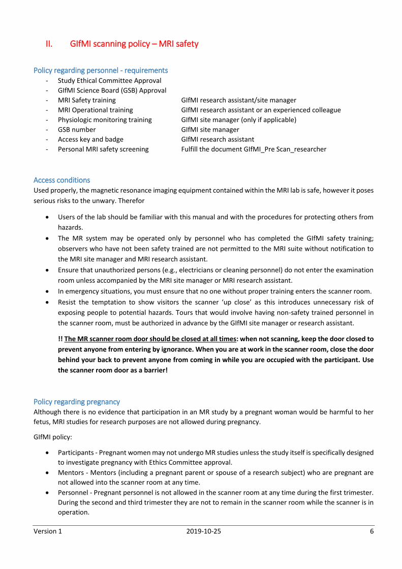
With at least one person on each side of the subject, move the participant towards the feet end so that
the head is no longer in the head coil.
Roll the participant towards you and slip the edge of the slide board under the side of the participant.
Slide the participant across the slide board towards the stretcher. The person standing next to the
stretcher should use his or her weight to hold the stretcher firmly against the scanner bed during the
transfer.
Once the participant is well situated on the stretcher, remove the slide board from beneath the
participant from whichever side is most convenient.
Put up the stretcher side rails and unlock the wheels. Move the stretcher away from the scan bed and out
of the scanner room.
Performing an emergency magnet quench: Magnet Stop switch
Situations requiring a Magnet Stop: Users of the GIfMI facility should only quench in the event that the magnetic field poses an immediate risk to life.
Two such circumstances are:
Risk of a participant death or major injury (e.g. a metal object is lodged in the scanner in a way that poses
an immediate serious threat to a person or a person is pinned to the magnet by a metal object).
Fire but only in case the fire personnel determines that there is no other alternative than to entering the
room with axes or other heavy gear when fighting a fire.
In the absence of a major emergency, facility users should never quench the magnet by themselves, even if they
are convinced that a magnet quench will ultimately be necessary (e.g. if a large object has been drawn into the
magnet, but poses no immediate risk to a person). Immediately notify the GIfMI site manager and research
assistant.
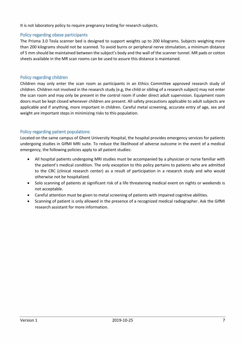
Quench procedure
Lift the glass cover and press the Magnet Stop switch in the control room or in the scanner room.
The magnetic field strength will fall to a level of 20 mT within 20 seconds. The helium is released via an
exhaust vent line (controlled quench). The helium vent ducts become dangerously cold during a quench.
Do not touch them.
Rescue participants immediately. If emergency medical assistance is needed, call in the emergency team
of Ghent University Hospital (call 81). For minor injury, accompany the participant to the emergency
department of the Hospital (building K12).
Immediately notify the GIfMI site manager and research assistant.
Version 1 2019-10-25 10
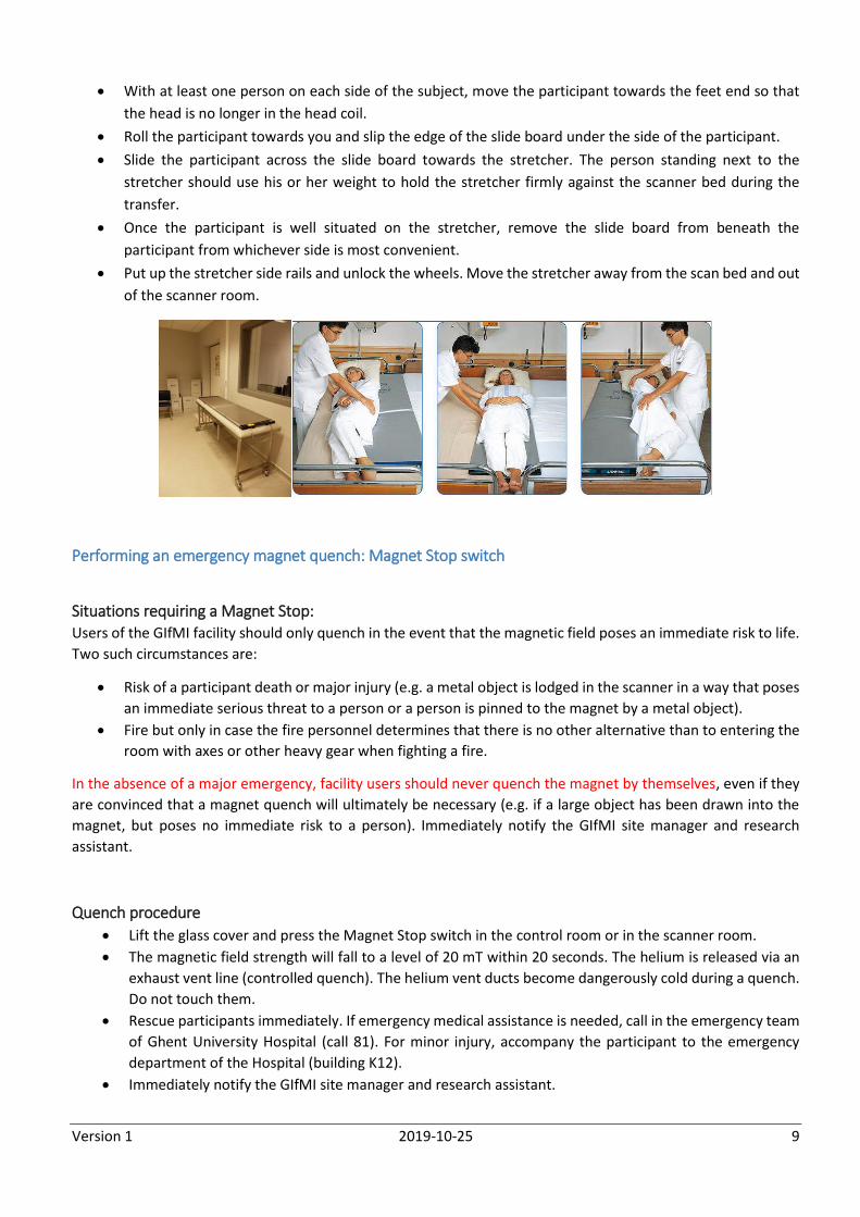
The magnet may be put back into operation only by Siemens personnel. At best it will take two days before the
scanner can be returned to service.
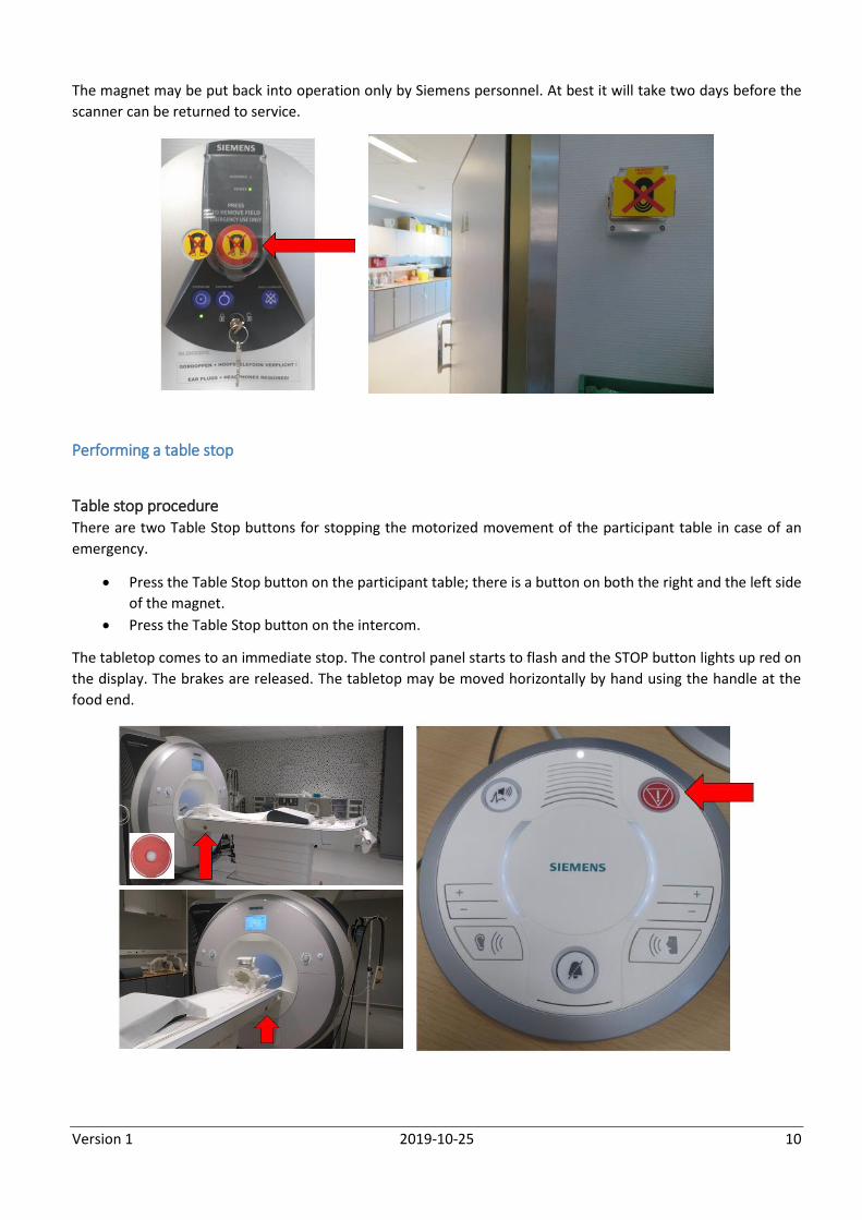
Performing a table stop
Table stop procedure There are two Table Stop buttons for stopping the motorized movement of the participant table in case of an
emergency.
Press the Table Stop button on the participant table; there is a button on both the right and the left side
of the magnet.
Press the Table Stop button on the intercom.
The tabletop comes to an immediate stop. The control panel starts to flash and the STOP button lights up red on
the display. The brakes are released. The tabletop may be moved horizontally by hand using the handle at the
food end.
Version 1 2019-10-25 11
Situations requiring a table stop:
In case of an accident
In case of risk of injury due to table movements
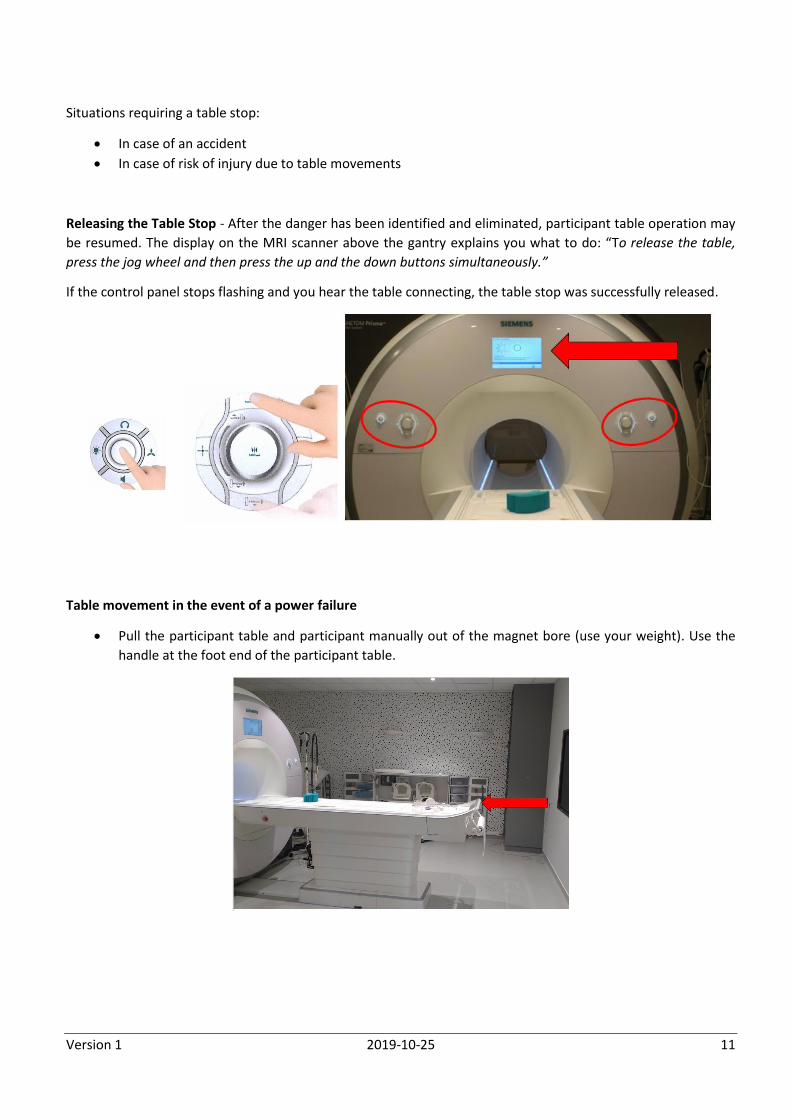
Releasing the Table Stop - After the danger has been identified and eliminated, participant table operation may
be resumed. The display on the MRI scanner above the gantry explains you what to do: “To release the table,
press the jog wheel and then press the up and the down buttons simultaneously.”
If the control panel stops flashing and you hear the table connecting, the table stop was successfully released.
Table movement in the event of a power failure
Pull the participant table and participant manually out of the magnet bore (use your weight). Use the
handle at the foot end of the participant table.

Version 1 2019-10-25 12
Fire safety In the event of fire
Attempt once to extinguish the fire. The fire extinguishers are MRI safe (labeled).
Call 88
Remove the participant from the scanner room.
Close the scanner room door.
Perform an emergency electrical shutdown.
Leave the MRI building.
Call the GIfMI research assistant and site manager.
Wait for the firemen to arrive. Fire fighters have to be able to take appropriate actions immediately. It is
your duty to remind the firemen of the magnetic field (that is always ON!) and to withdraw them from
entering the MRI scanner room with MRI non compatible equipment!
Only quench in case the fire personnel determines that there is no other alternative than to entering the
room with axes or other heavy gear when fighting a fire.
Version 1 2019-10-25 13
IV. THE GIFMI FACILITY
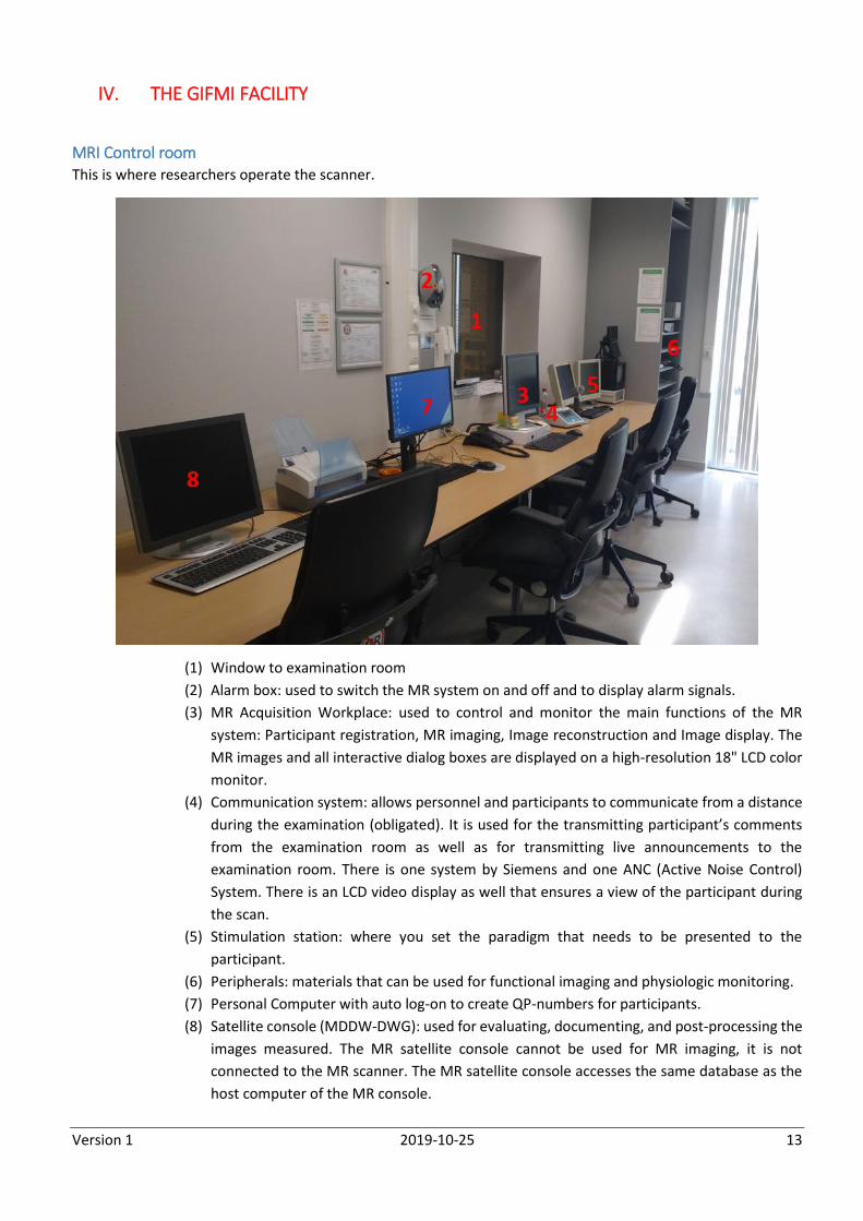
MRI Control room This is where researchers operate the scanner.
(1) Window to examination room
(2) Alarm box: used to switch the MR system on and off and to display alarm signals.
(3) MR Acquisition Workplace: used to control and monitor the main functions of the MR
system: Participant registration, MR imaging, Image reconstruction and Image display. The
MR images and all interactive dialog boxes are displayed on a high-resolution 18" LCD color
monitor.
(4) Communication system: allows personnel and participants to communicate from a distance
during the examination (obligated). It is used for the transmitting participant’s comments
from the examination room as well as for transmitting live announcements to the
examination room. There is one system by Siemens and one ANC (Active Noise Control)
System. There is an LCD video display as well that ensures a view of the participant during
the scan.
(5) Stimulation station: where you set the paradigm that needs to be presented to the
participant.
(6) Peripherals: materials that can be used for functional imaging and physiologic monitoring.
(7) Personal Computer with auto log-on to create QP-numbers for participants.
(8) Satellite console (MDDW-DWG): used for evaluating, documenting, and post-processing the
images measured. The MR satellite console cannot be used for MR imaging, it is not
connected to the MR scanner. The MR satellite console accesses the same database as the
host computer of the MR console.
Version 1 2019-10-25 14
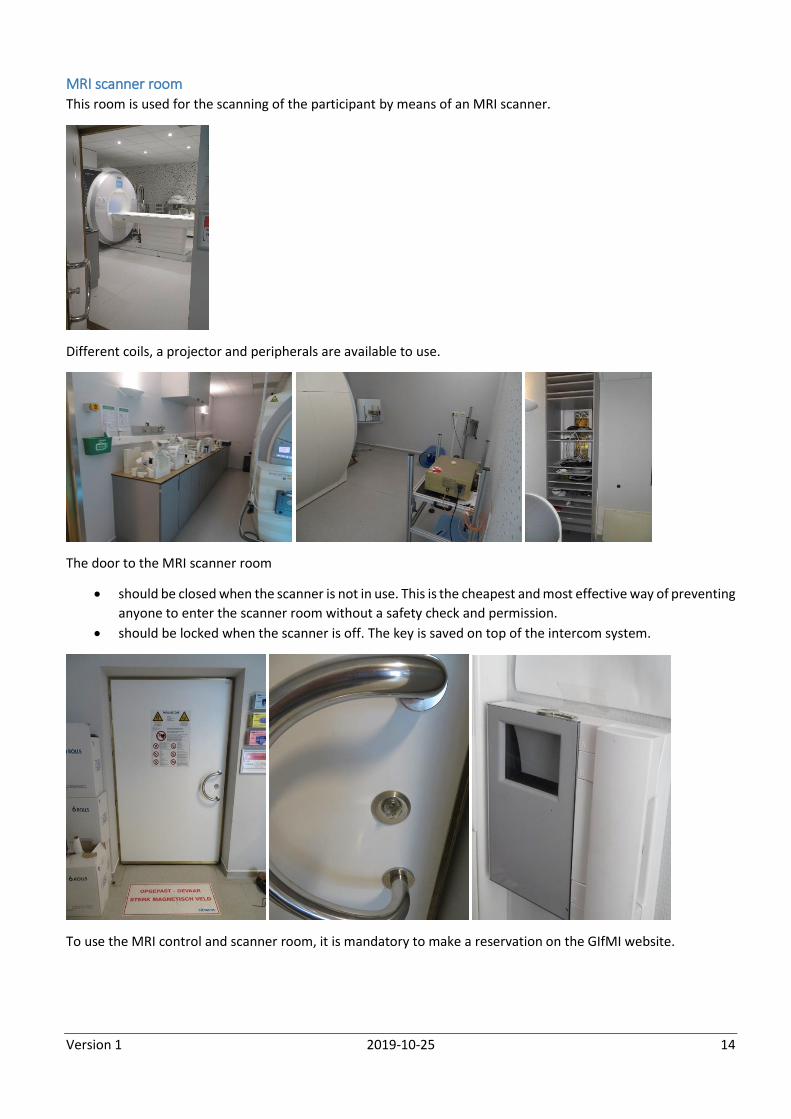
MRI scanner room This room is used for the scanning of the participant by means of an MRI scanner.
Different coils, a projector and peripherals are available to use.
The door to the MRI scanner room
should be closed when the scanner is not in use. This is the cheapest and most effective way of preventing
anyone to enter the scanner room without a safety check and permission.
should be locked when the scanner is off. The key is saved on top of the intercom system.
To use the MRI control and scanner room, it is mandatory to make a reservation on the GIfMI website.
Version 1 2019-10-25 15
Equipment in the MRI scanner room
MRI coils
Many MRI coils for different purposes are available. Put every coil back in place (see the labels on the closet) after
use. The default coil for neuroimaging is the 64 channel head coil.
Phantoms are stored in the closet. They often contain carcinogens, handle with care. Phantoms can be used to
test sequences without having to put a participant in the scanner.
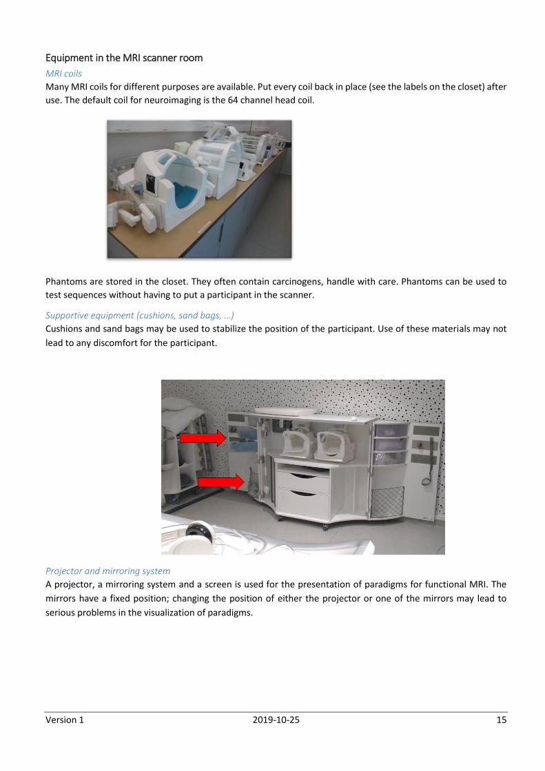
Supportive equipment (cushions, sand bags, …)
Cushions and sand bags may be used to stabilize the position of the participant. Use of these materials may not
lead to any discomfort for the participant.
Projector and mirroring system
A projector, a mirroring system and a screen is used for the presentation of paradigms for functional MRI. The
mirrors have a fixed position; changing the position of either the projector or one of the mirrors may lead to
serious problems in the visualization of paradigms.
Version 1 2019-10-25 16
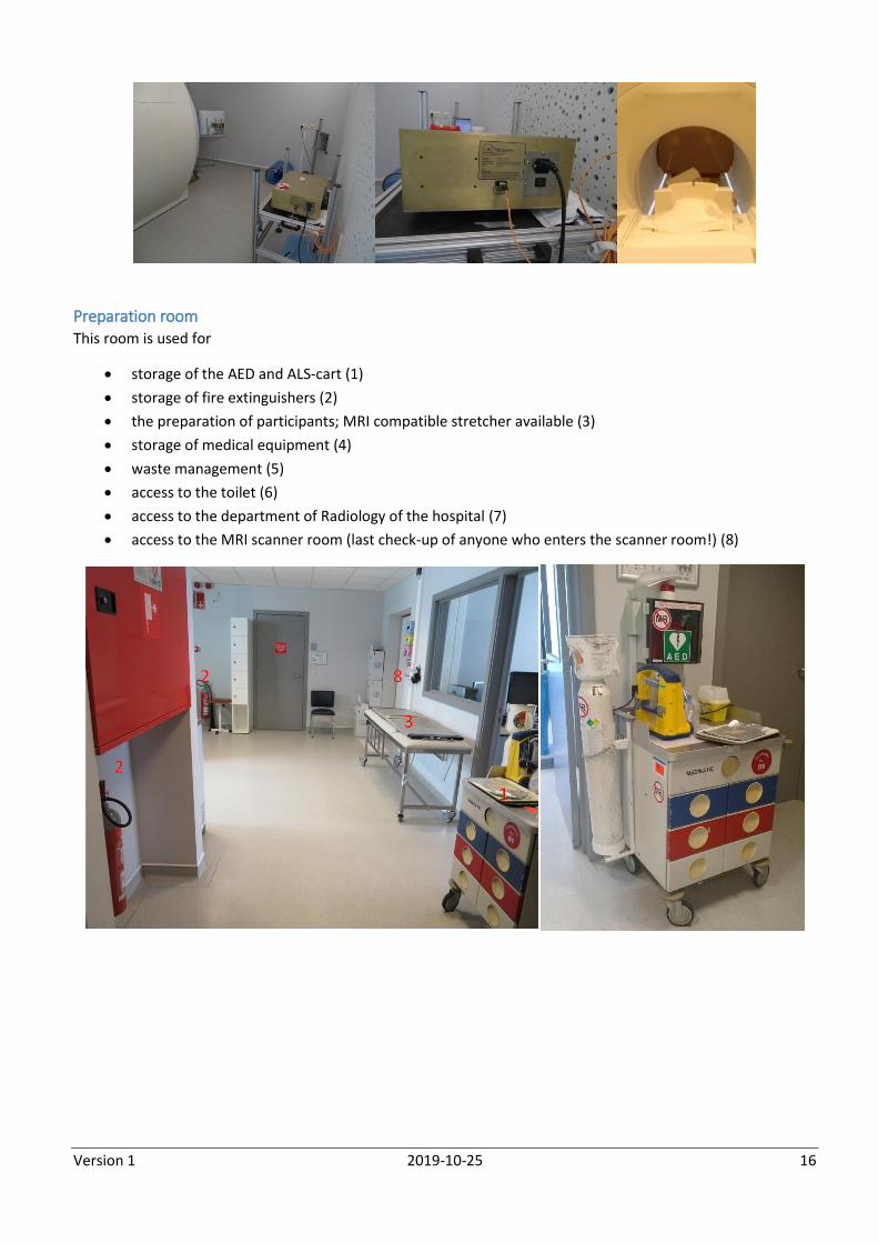
Preparation room This room is used for
storage of the AED and ALS-cart (1)
storage of fire extinguishers (2)
the preparation of participants; MRI compatible stretcher available (3)
storage of medical equipment (4)
waste management (5)
access to the toilet (6)
access to the department of Radiology of the hospital (7)
access to the MRI scanner room (last check-up of anyone who enters the scanner room!) (8)
Version 1 2019-10-25 17
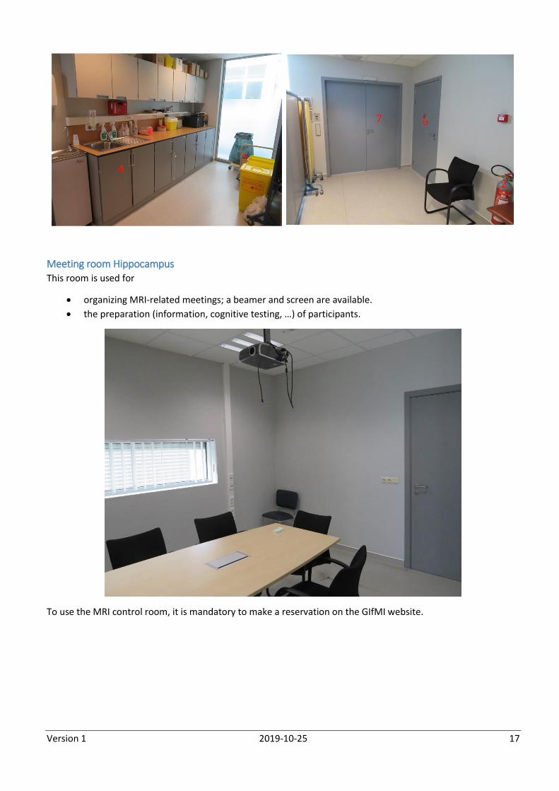
Meeting room Hippocampus This room is used for
organizing MRI-related meetings; a beamer and screen are available.
the preparation (information, cognitive testing, …) of participants.
To use the MRI control room, it is mandatory to make a reservation on the GIfMI website.
Version 1 2019-10-25 18
V. GETTING STARTED: MRI USER MANUAL
a. Switching on/off the scanner and satellite console
Switching the MRI system ON If you arrive first in the morning, you will have to start up the scanner. Starting the system includes the following
steps:
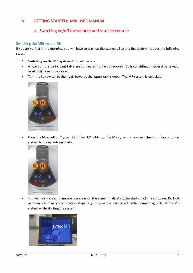
1. Switching on the MR system at the alarm box
All coils on the participant table are connected to the coil sockets. Coils consisting of several parts (e.g.,
head coil) have to be closed.
Turn the key switch to the right, towards the ‘open lock’ symbol. The MR system is unlocked.
Press the blue button ‘System On’. The LED lights up. The MR system is now switched on. The computer
system boots up automatically.
You will see increasing numbers appear on the screen, indicating the start-up of the software. Do NOT
perform preliminary examination steps (e.g., moving the participant table, connecting coils) at the MR
system while starting the system!
Version 1 2019-10-25 19
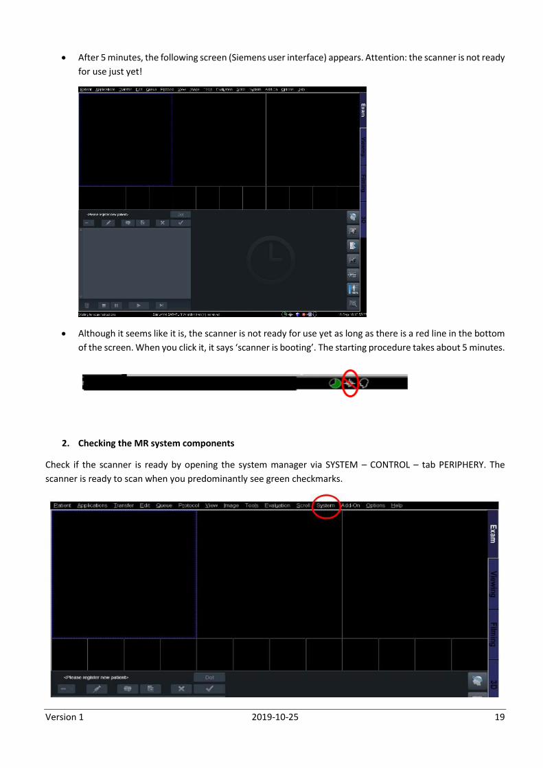
After 5 minutes, the following screen (Siemens user interface) appears. Attention: the scanner is not ready
for use just yet!
Although it seems like it is, the scanner is not ready for use yet as long as there is a red line in the bottom
of the screen. When you click it, it says ‘scanner is booting’. The starting procedure takes about 5 minutes.
2. Checking the MR system components
Check if the scanner is ready by opening the system manager via SYSTEM – CONTROL – tab PERIPHERY. The
scanner is ready to scan when you predominantly see green checkmarks.
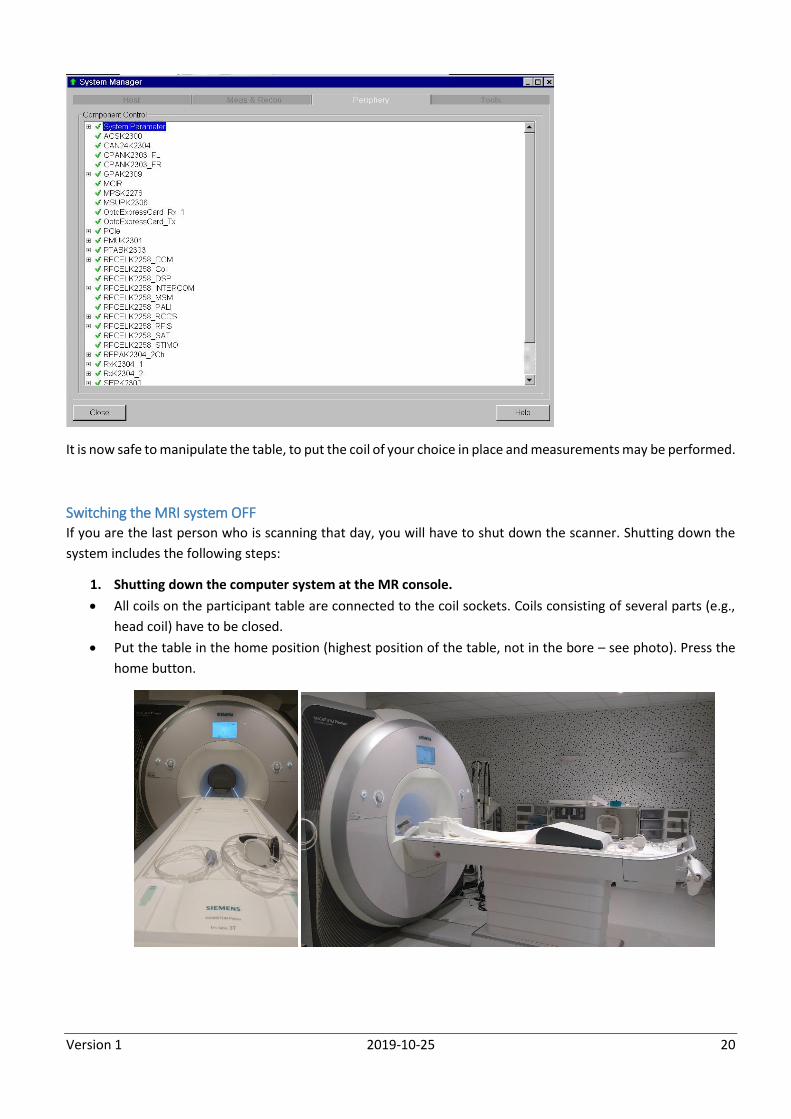
Version 1 2019-10-25 20
It is now safe to manipulate the table, to put the coil of your choice in place and measurements may be performed.
Switching the MRI system OFF If you are the last person who is scanning that day, you will have to shut down the scanner. Shutting down the
system includes the following steps:
1. Shutting down the computer system at the MR console.
All coils on the participant table are connected to the coil sockets. Coils consisting of several parts (e.g.,
head coil) have to be closed.
Put the table in the home position (highest position of the table, not in the bore – see photo). Press the
home button.
Version 1 2019-10-25 21
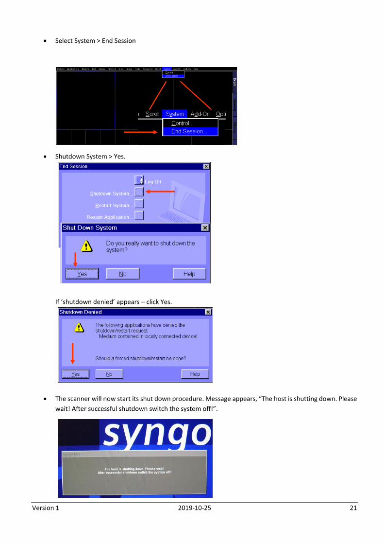
Select System > End Session
Shutdown System > Yes.
If ‘shutdown denied’ appears – click Yes.
The scanner will now start its shut down procedure. Message appears, “The host is shutting down. Please
wait! After successful shutdown switch the system off!”.
Version 1 2019-10-25 22
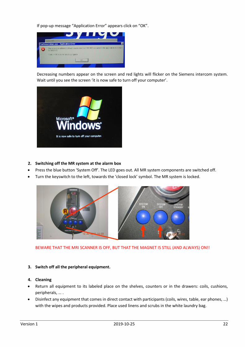
If pop-up message “Application Error” appears click on “OK”.
Decreasing numbers appear on the screen and red lights will flicker on the Siemens intercom system.
Wait until you see the screen ‘it is now safe to turn off your computer’.
2. Switching off the MR system at the alarm box
Press the blue button ‘System Off’. The LED goes out. All MR system components are switched off.
Turn the keyswitch to the left, towards the ‘closed lock’ symbol. The MR system is locked.
BEWARE THAT THE MRI SCANNER IS OFF, BUT THAT THE MAGNET IS STILL (AND ALWAYS) ON!!
3. Switch off all the peripheral equipment.
4. Cleaning
Return all equipment to its labeled place on the shelves, counters or in the drawers: coils, cushions,
peripherals, … .
Disinfect any equipment that comes in direct contact with participants (coils, wires, table, ear phones, …)
with the wipes and products provided. Place used linens and scrubs in the white laundry bag.
Version 1 2019-10-25 23
5. Closing the MRI facility
Leave the MRI scanner facility as neat as you found it: MRI scanner equipment cleaned, chairs in place,
waste in the bins, curtains closed.
Turn off all the lights.
Lock the door of the scanner room (put the Siemens key on the intercom system), the console room and
the MRI building (same key).
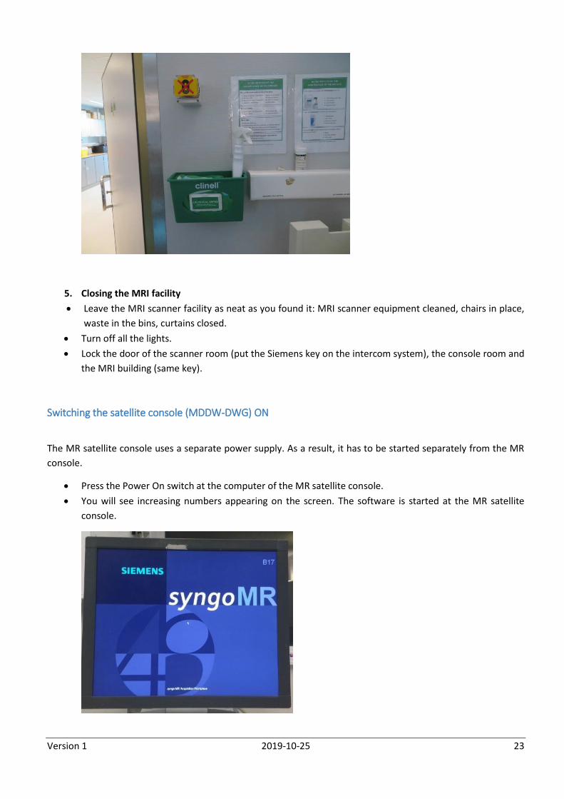
Switching the satellite console (MDDW-DWG) ON
The MR satellite console uses a separate power supply. As a result, it has to be started separately from the MR
console.
Press the Power On switch at the computer of the MR satellite console.
You will see increasing numbers appearing on the screen. The software is started at the MR satellite
console.
Version 1 2019-10-25 24
Eventually, the following screen appears on the satellite console:
The satellite console is ready for use.
Switching the satellite console OFF The MR satellite console uses a separate power supply. As a result, it has to be shut down separately from the MR
console. Simultaneously press the Ctrl, Alt, and Del keys on the keyboard. The Windows NT Security window is
displayed. Click the Shut Down button to shut down the software. Repeat to shut down the hardware.
b. Communication between participant and researcher
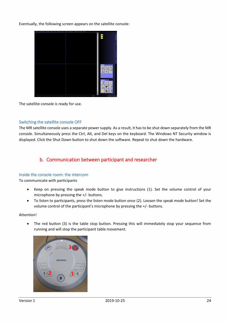
Inside the console room: the intercom To communicate with participants
Keep on pressing the speak mode button to give instructions (1). Set the volume control of your
microphone by pressing the +/- buttons.
To listen to participants, press the listen mode button once (2). Loosen the speak mode button! Set the
volume control of the participant’s microphone by pressing the +/- buttons.
Attention!
The red button (3) is the table stop button. Pressing this will immediately stop your sequence from
running and will stop the participant table movement.
Version 1 2019-10-25 25
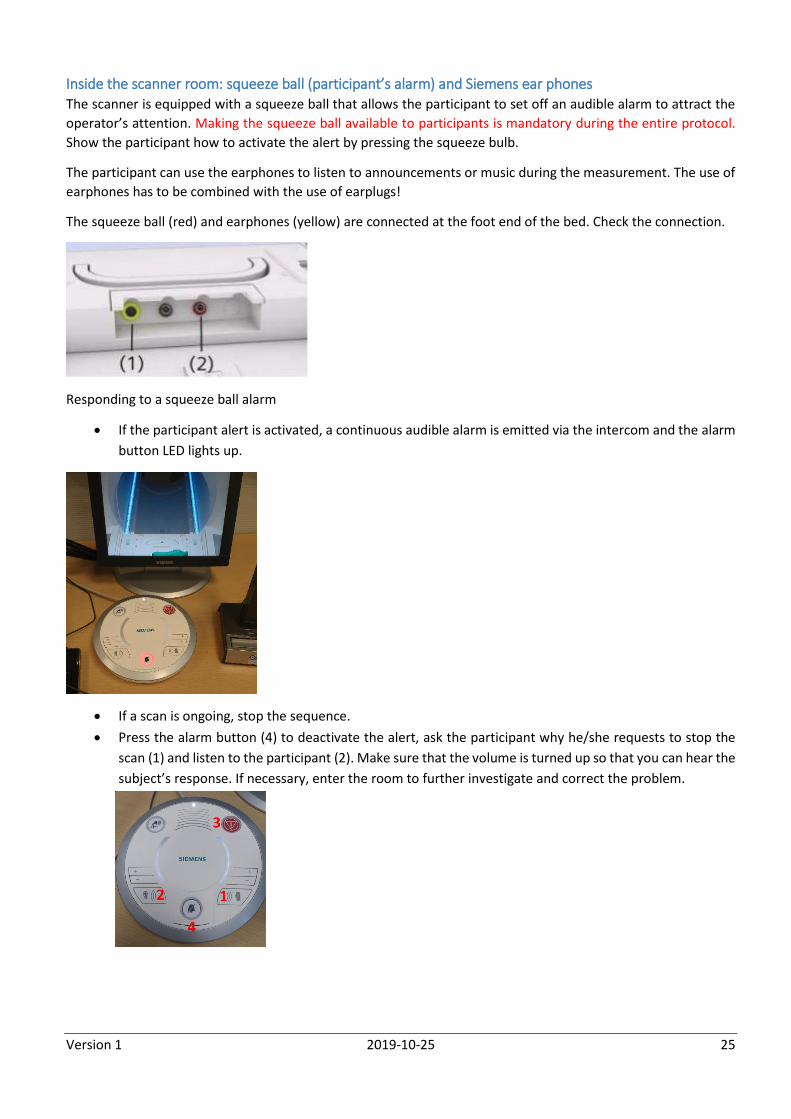
Inside the scanner room: squeeze ball (participant’s alarm) and Siemens ear phones The scanner is equipped with a squeeze ball that allows the participant to set off an audible alarm to attract the
operator’s attention. Making the squeeze ball available to participants is mandatory during the entire protocol.
Show the participant how to activate the alert by pressing the squeeze bulb.
The participant can use the earphones to listen to announcements or music during the measurement. The use of
earphones has to be combined with the use of earplugs!
The squeeze ball (red) and earphones (yellow) are connected at the foot end of the bed. Check the connection.
Responding to a squeeze ball alarm
If the participant alert is activated, a continuous audible alarm is emitted via the intercom and the alarm
button LED lights up.
If a scan is ongoing, stop the sequence.
Press the alarm button (4) to deactivate the alert, ask the participant why he/she requests to stop the
scan (1) and listen to the participant (2). Make sure that the volume is turned up so that you can hear the
subject’s response. If necessary, enter the room to further investigate and correct the problem.
Version 1 2019-10-25 26
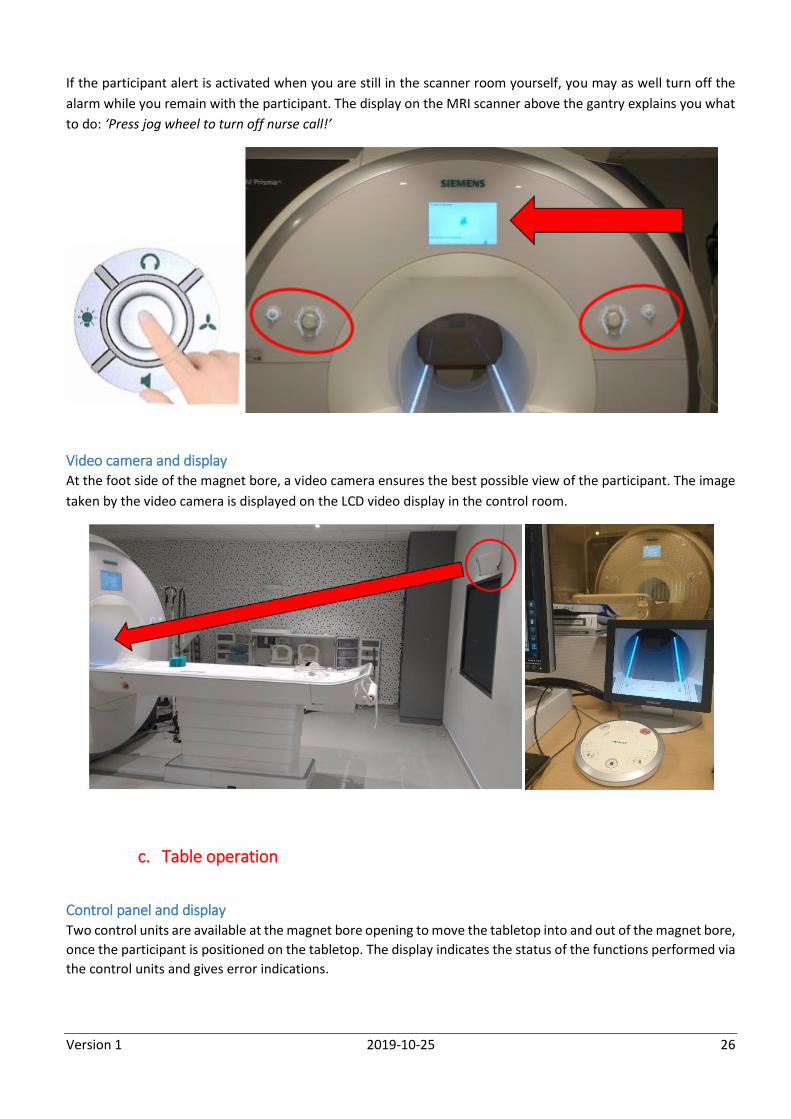
If the participant alert is activated when you are still in the scanner room yourself, you may as well turn off the
alarm while you remain with the participant. The display on the MRI scanner above the gantry explains you what
to do: ‘Press jog wheel to turn off nurse call!’
Video camera and display At the foot side of the magnet bore, a video camera ensures the best possible view of the participant. The image
taken by the video camera is displayed on the LCD video display in the control room.
c. Table operation
Control panel and display Two control units are available at the magnet bore opening to move the tabletop into and out of the magnet bore,
once the participant is positioned on the tabletop. The display indicates the status of the functions performed via
the control units and gives error indications.
Version 1 2019-10-25 27
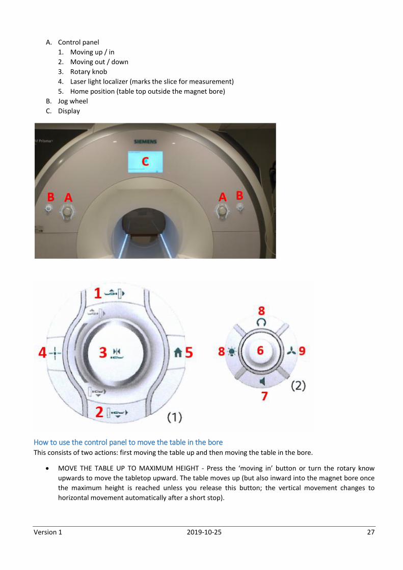
A. Control panel
1. Moving up / in
2. Moving out / down
3. Rotary knob
4. Laser light localizer (marks the slice for measurement)
5. Home position (table top outside the magnet bore)
B. Jog wheel
C. Display
How to use the control panel to move the table in the bore This consists of two actions: first moving the table up and then moving the table in the bore.
MOVE THE TABLE UP TO MAXIMUM HEIGHT - Press the ‘moving in’ button or turn the rotary know
upwards to move the tabletop upward. The table moves up (but also inward into the magnet bore once
the maximum height is reached unless you release this button; the vertical movement changes to
horizontal movement automatically after a short stop).
Version 1 2019-10-25 28
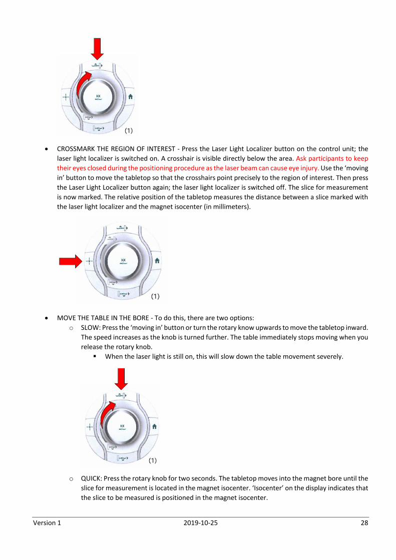
CROSSMARK THE REGION OF INTEREST - Press the Laser Light Localizer button on the control unit; the
laser light localizer is switched on. A crosshair is visible directly below the area. Ask participants to keep
their eyes closed during the positioning procedure as the laser beam can cause eye injury. Use the ‘moving
in’ button to move the tabletop so that the crosshairs point precisely to the region of interest. Then press
the Laser Light Localizer button again; the laser light localizer is switched off. The slice for measurement
is now marked. The relative position of the tabletop measures the distance between a slice marked with
the laser light localizer and the magnet isocenter (in millimeters).
MOVE THE TABLE IN THE BORE - To do this, there are two options:
o SLOW: Press the ‘moving in’ button or turn the rotary know upwards to move the tabletop inward.
The speed increases as the knob is turned further. The table immediately stops moving when you
release the rotary knob.
When the laser light is still on, this will slow down the table movement severely.
o QUICK: Press the rotary knob for two seconds. The tabletop moves into the magnet bore until the
slice for measurement is located in the magnet isocenter. ‘Isocenter’ on the display indicates that
the slice to be measured is positioned in the magnet isocenter.
Version 1 2019-10-25 29
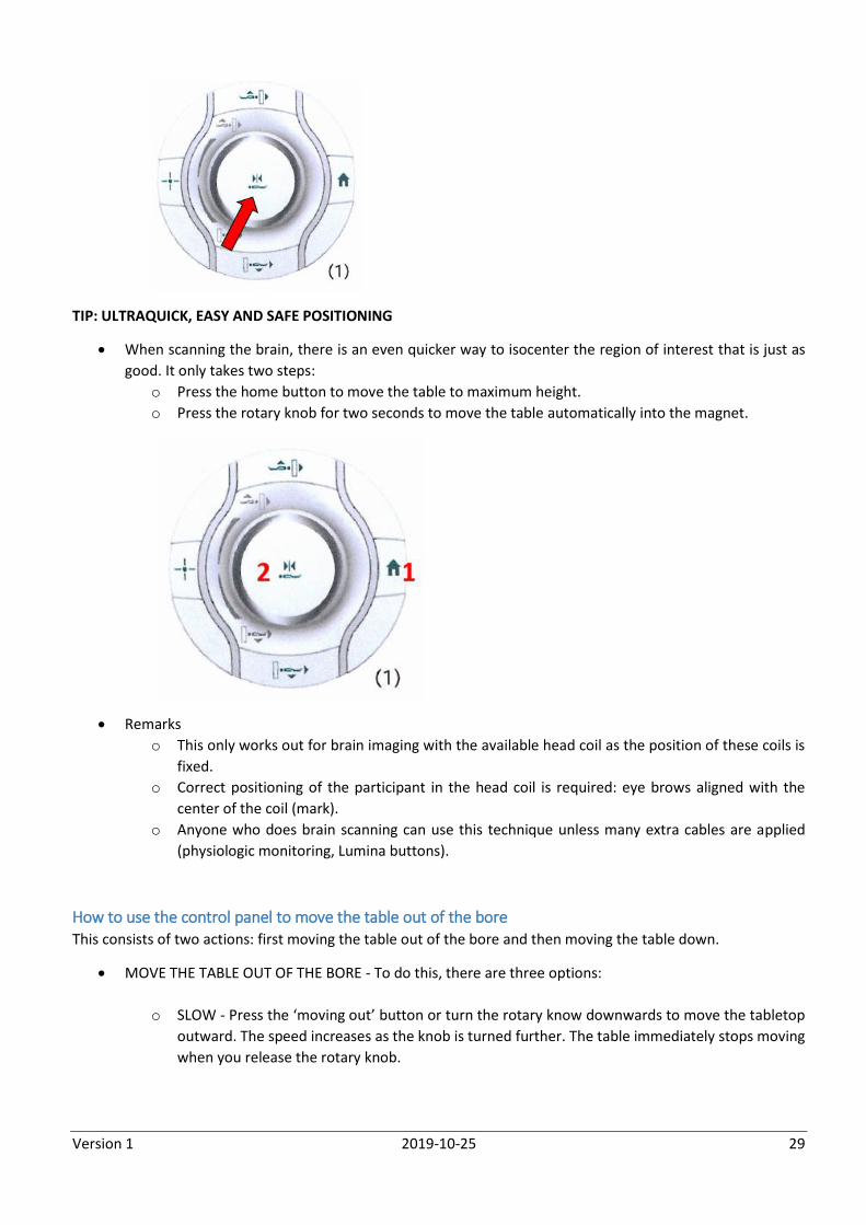
TIP: ULTRAQUICK, EASY AND SAFE POSITIONING
When scanning the brain, there is an even quicker way to isocenter the region of interest that is just as
good. It only takes two steps:
o Press the home button to move the table to maximum height.
o Press the rotary knob for two seconds to move the table automatically into the magnet.
Remarks
o This only works out for brain imaging with the available head coil as the position of these coils is
fixed.
o Correct positioning of the participant in the head coil is required: eye brows aligned with the
center of the coil (mark).
o Anyone who does brain scanning can use this technique unless many extra cables are applied
(physiologic monitoring, Lumina buttons).
How to use the control panel to move the table out of the bore This consists of two actions: first moving the table out of the bore and then moving the table down.
MOVE THE TABLE OUT OF THE BORE - To do this, there are three options:
o SLOW - Press the ‘moving out’ button or turn the rotary know downwards to move the tabletop
outward. The speed increases as the knob is turned further. The table immediately stops moving
when you release the rotary knob.
Version 1 2019-10-25 30
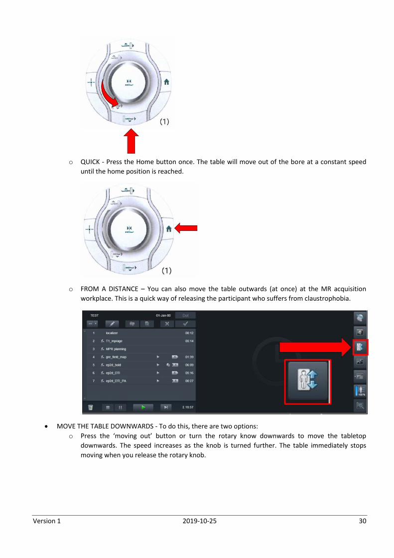
o QUICK - Press the Home button once. The table will move out of the bore at a constant speed
until the home position is reached.
o FROM A DISTANCE – You can also move the table outwards (at once) at the MR acquisition
workplace. This is a quick way of releasing the participant who suffers from claustrophobia.
MOVE THE TABLE DOWNWARDS - To do this, there are two options:
o Press the ‘moving out’ button or turn the rotary know downwards to move the tabletop
downwards. The speed increases as the knob is turned further. The table immediately stops
moving when you release the rotary knob.
Version 1 2019-10-25 31
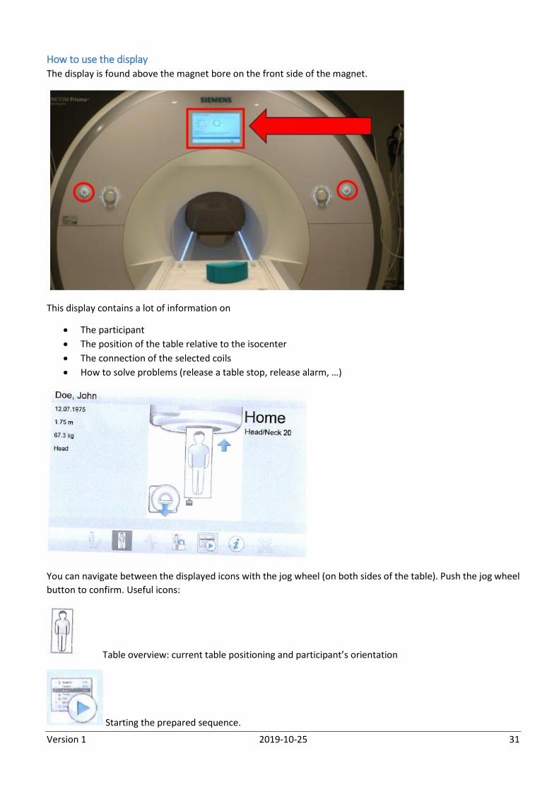
How to use the display The display is found above the magnet bore on the front side of the magnet.
This display contains a lot of information on
The participant
The position of the table relative to the isocenter
The connection of the selected coils
How to solve problems (release a table stop, release alarm, …)
You can navigate between the displayed icons with the jog wheel (on both sides of the table). Push the jog wheel
button to confirm. Useful icons:
Table overview: current table positioning and participant’s orientation
Starting the prepared sequence.
Version 1 2019-10-25 32
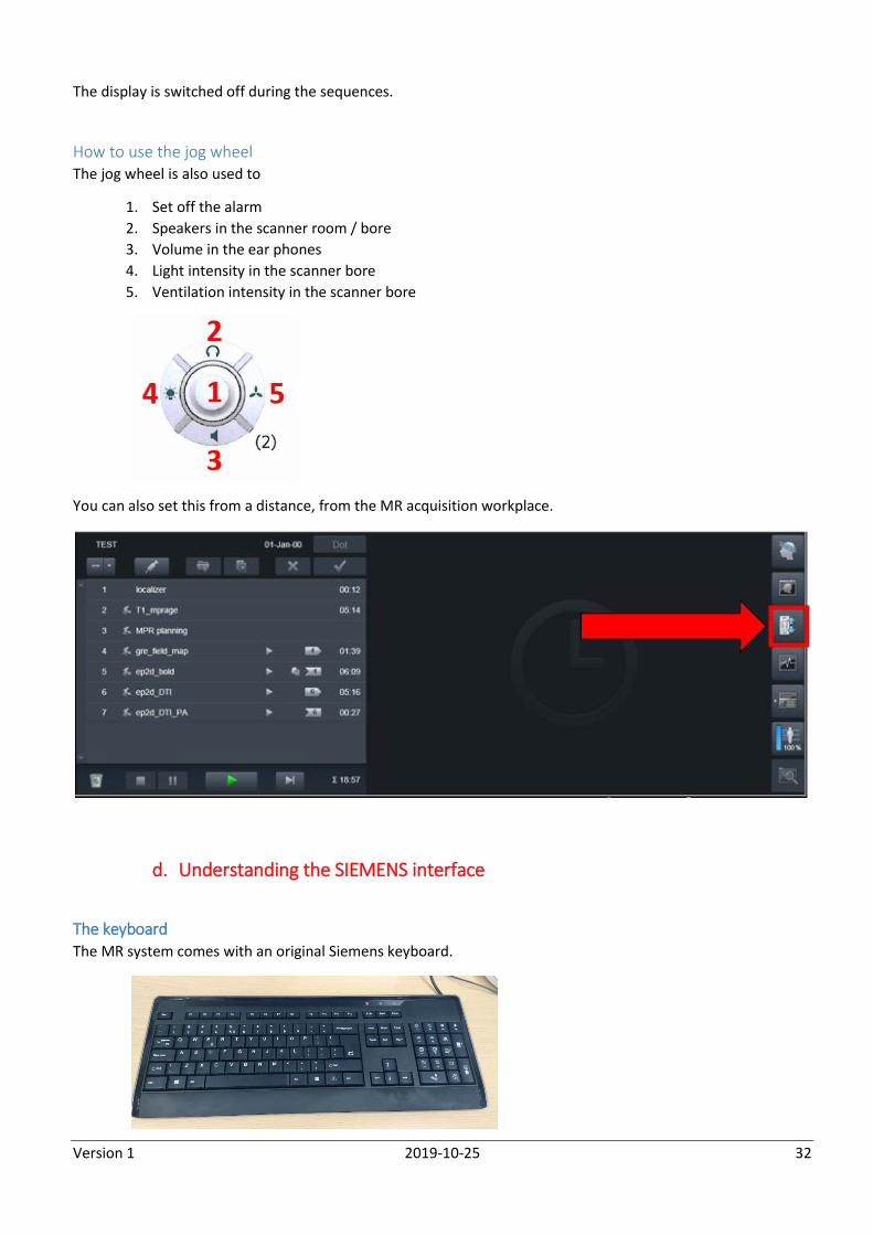
The display is switched off during the sequences.
How to use the jog wheel The jog wheel is also used to
1. Set off the alarm
2. Speakers in the scanner room / bore
3. Volume in the ear phones
4. Light intensity in the scanner bore
5. Ventilation intensity in the scanner bore
You can also set this from a distance, from the MR acquisition workplace.
d. Understanding the SIEMENS interface
The keyboard The MR system comes with an original Siemens keyboard.
Version 1 2019-10-25 33
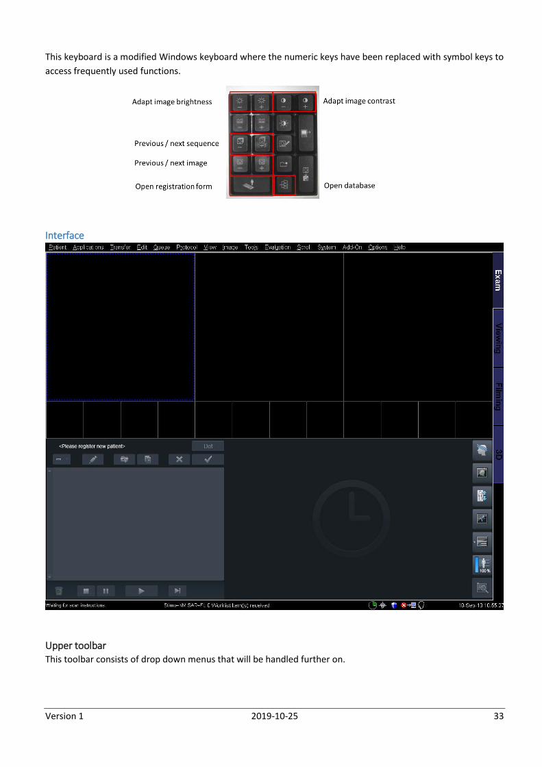
This keyboard is a modified Windows keyboard where the numeric keys have been replaced with symbol keys to
access frequently used functions.
Interface
Upper toolbar This toolbar consists of drop down menus that will be handled further on.
Version 1 2019-10-25 34
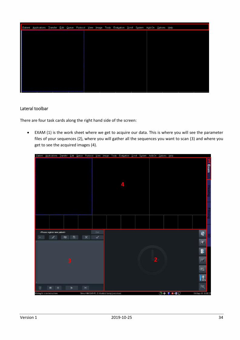
Lateral toolbar
There are four task cards along the right hand side of the screen:
EXAM (1) is the work sheet where we get to acquire our data. This is where you will see the parameter
files of your sequences (2), where you will gather all the sequences you want to scan (3) and where you
get to see the acquired images (4).
Version 1 2019-10-25 35
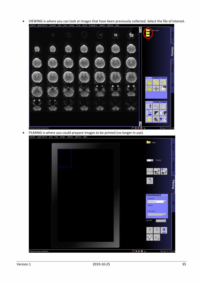
VIEWING is where you can look at images that have been previously collected. Select the file of interest.
FILMING is where you could prepare images to be printed (no longer in use).
Version 1 2019-10-25 36
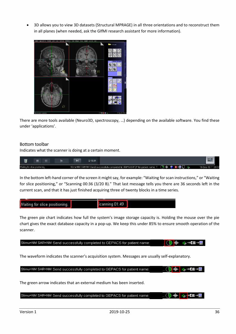
3D allows you to view 3D datasets (Structural MPRAGE) in all three orientations and to reconstruct them
in all planes (when needed, ask the GIfMI research assistant for more information).
There are more tools available (Neuro3D, spectroscopy, …) depending on the available software. You find these
under ‘applications’.
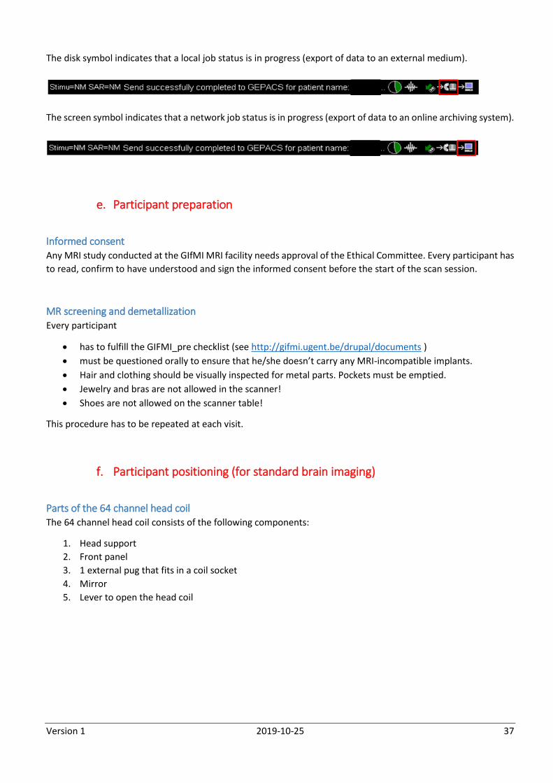
Bottom toolbar Indicates what the scanner is doing at a certain moment.
In the bottom left-hand corner of the screen it might say, for example: “Waiting for scan instructions,” or “Waiting
for slice positioning,” or “Scanning 00:36 (3/20 B).” That last message tells you there are 36 seconds left in the
current scan, and that it has just finished acquiring three of twenty blocks in a time series.
The green pie chart indicates how full the system’s image storage capacity is. Holding the mouse over the pie
chart gives the exact database capacity in a pop-up. We keep this under 85% to ensure smooth operation of the
scanner.
The waveform indicates the scanner’s acquisition system. Messages are usually self-explanatory.
The green arrow indicates that an external medium has been inserted.
Version 1 2019-10-25 37
The disk symbol indicates that a local job status is in progress (export of data to an external medium).
The screen symbol indicates that a network job status is in progress (export of data to an online archiving system).
e. Participant preparation
Informed consent Any MRI study conducted at the GIfMI MRI facility needs approval of the Ethical Committee. Every participant has
to read, confirm to have understood and sign the informed consent before the start of the scan session.
MR screening and demetallization Every participant
has to fulfill the GIFMI_pre checklist (see http://gifmi.ugent.be/drupal/documents )
must be questioned orally to ensure that he/she doesn’t carry any MRI-incompatible implants.
Hair and clothing should be visually inspected for metal parts. Pockets must be emptied.
Jewelry and bras are not allowed in the scanner!
Shoes are not allowed on the scanner table!
This procedure has to be repeated at each visit.
f. Participant positioning (for standard brain imaging)
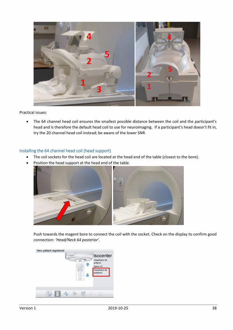
Parts of the 64 channel head coil The 64 channel head coil consists of the following components:
1. Head support
2. Front panel
3. 1 external pug that fits in a coil socket
4. Mirror
5. Lever to open the head coil
Version 1 2019-10-25 38
Practical issues:
The 64 channel head coil ensures the smallest possible distance between the coil and the participant’s
head and is therefore the default head coil to use for neuroimaging. If a participant’s head doesn’t fit in,
try the 20 channel head coil instead; be aware of the lower SNR.
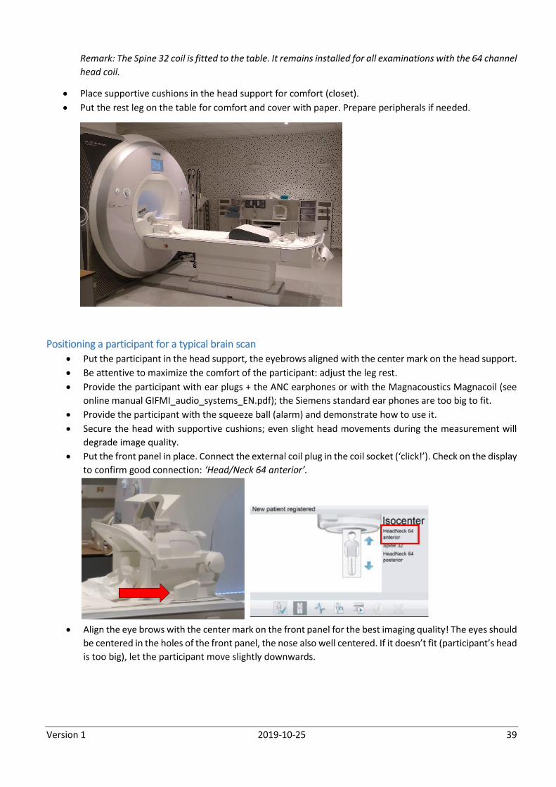
Installing the 64 channel head coil (head support)
The coil sockets for the head coil are located at the head end of the table (closest to the bore).
Position the head support at the head end of the table.
Push towards the magent bore to connect the coil with the socket. Check on the display to confirm good
connection: ‘Head/Neck 64 posterior’.
Version 1 2019-10-25 39
Remark: The Spine 32 coil is fitted to the table. It remains installed for all examinations with the 64 channel
head coil.
Place supportive cushions in the head support for comfort (closet).
Put the rest leg on the table for comfort and cover with paper. Prepare peripherals if needed.
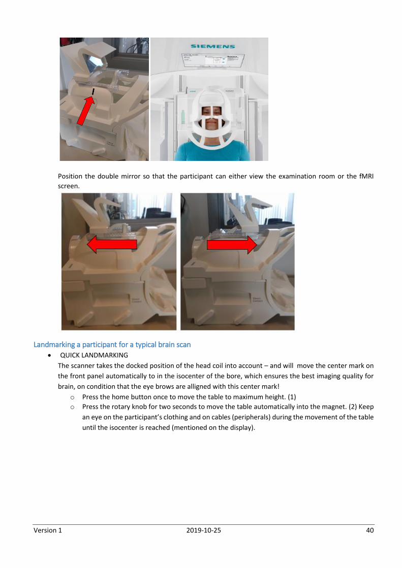
Positioning a participant for a typical brain scan
Put the participant in the head support, the eyebrows aligned with the center mark on the head support.
Be attentive to maximize the comfort of the participant: adjust the leg rest.
Provide the participant with ear plugs + the ANC earphones or with the Magnacoustics Magnacoil (see
online manual GIFMI_audio_systems_EN.pdf); the Siemens standard ear phones are too big to fit.
Provide the participant with the squeeze ball (alarm) and demonstrate how to use it.
Secure the head with supportive cushions; even slight head movements during the measurement will
degrade image quality.
Put the front panel in place. Connect the external coil plug in the coil socket (‘click!’). Check on the display
to confirm good connection: ‘Head/Neck 64 anterior’.
Align the eye brows with the center mark on the front panel for the best imaging quality! The eyes should
be centered in the holes of the front panel, the nose also well centered. If it doesn’t fit (participant’s head
is too big), let the participant move slightly downwards.
Version 1 2019-10-25 40
Position the double mirror so that the participant can either view the examination room or the fMRI
screen.
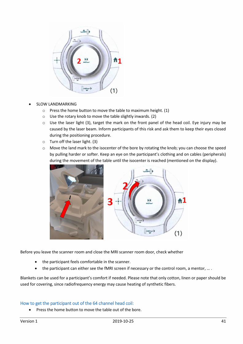
Landmarking a participant for a typical brain scan
QUICK LANDMARKING
The scanner takes the docked position of the head coil into account – and will move the center mark on
the front panel automatically to in the isocenter of the bore, which ensures the best imaging quality for
brain, on condition that the eye brows are alligned with this center mark!
o Press the home button once to move the table to maximum height. (1)
o Press the rotary knob for two seconds to move the table automatically into the magnet. (2) Keep
an eye on the participant’s clothing and on cables (peripherals) during the movement of the table
until the isocenter is reached (mentioned on the display).
Version 1 2019-10-25 41
SLOW LANDMARKING
o Press the home button to move the table to maximum height. (1)
o Use the rotary knob to move the table slightly inwards. (2)
o Use the laser light (3), target the mark on the front panel of the head coil. Eye injury may be
caused by the laser beam. Inform participants of this risk and ask them to keep their eyes closed
during the positioning procedure.
o Turn off the laser light. (3)
o Move the land mark to the isocenter of the bore by rotating the knob; you can choose the speed
by pulling harder or softer. Keep an eye on the participant’s clothing and on cables (peripherals)
during the movement of the table until the isocenter is reached (mentioned on the display).
Before you leave the scanner room and close the MRI scanner room door, check whether
the participant feels comfortable in the scanner.
the participant can either see the fMRI screen if necessary or the control room, a mentor, … .
Blankets can be used for a participant’s comfort if needed. Please note that only cotton, linen or paper should be
used for covering, since radiofrequency energy may cause heating of synthetic fibers.
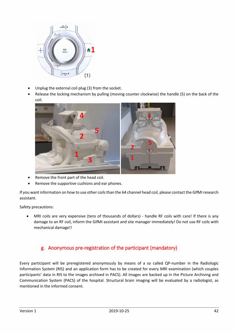
How to get the participant out of the 64 channel head coil:
Press the home button to move the table out of the bore.
Version 1 2019-10-25 42
Unplug the external coil plug (3) from the socket.
Release the locking mechanism by pulling (moving counter clockwise) the handle (5) on the back of the
coil.
Remove the front part of the head coil.
Remove the supportive cushions and ear phones.
If you want information on how to use other coils than the 64 channel head coil, please contact the GIfMI research
assistant.
Safety precautions:
MRI coils are very expensive (tens of thousands of dollars) - handle RF coils with care! If there is any
damage to an RF coil, inform the GIfMI assistant and site manager immediately! Do not use RF coils with
mechanical damage!!
g. Anonymous pre-registration of the participant (mandatory)
Every participant will be preregistered anonymously by means of a so called QP-number in the Radiologic
Information System (RIS) and an application form has to be created for every MRI examination (which couples
participants’ data in RIS to the images archived in PACS). All images are backed up in the Picture Archiving and
Communication System (PACS) of the hospital. Structural brain imaging will be evaluated by a radiologist, as
mentioned in the informed consent.
Version 1 2019-10-25 43
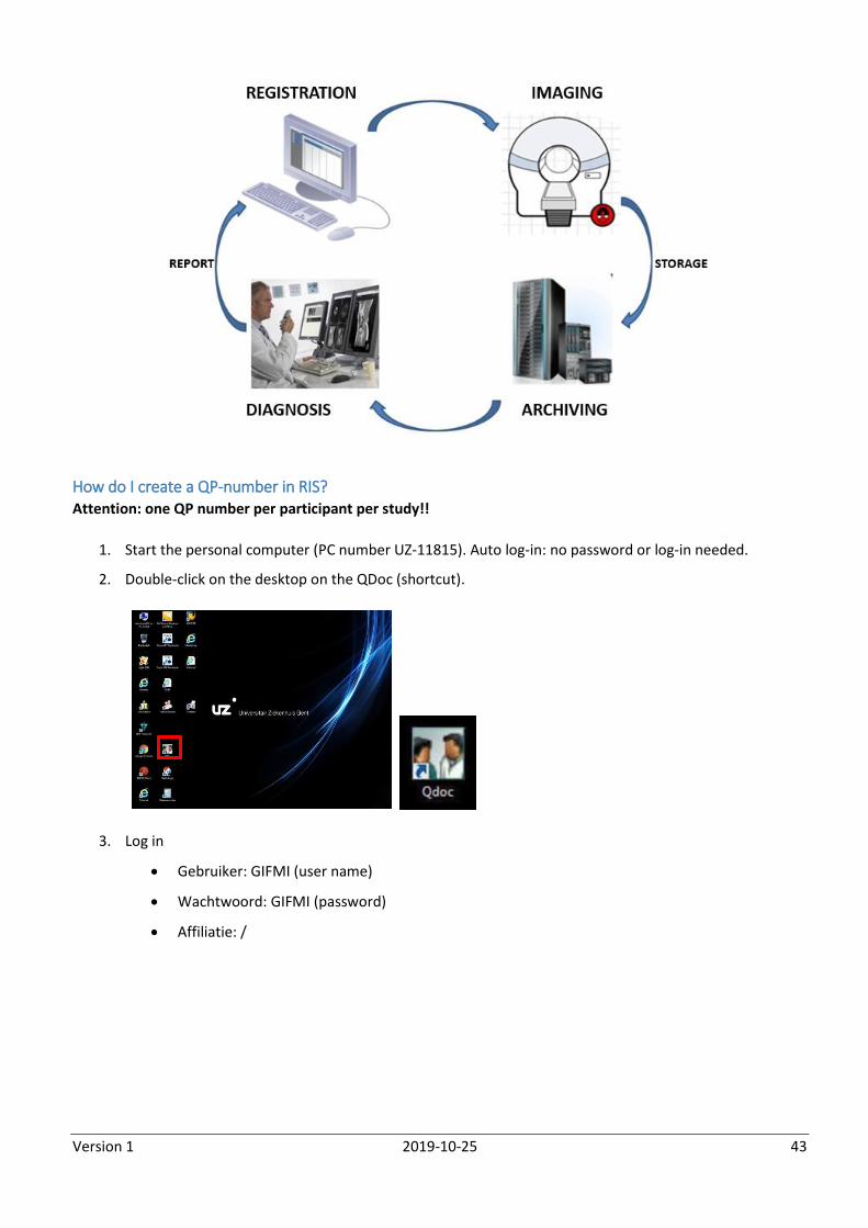
How do I create a QP-number in RIS? Attention: one QP number per participant per study!!
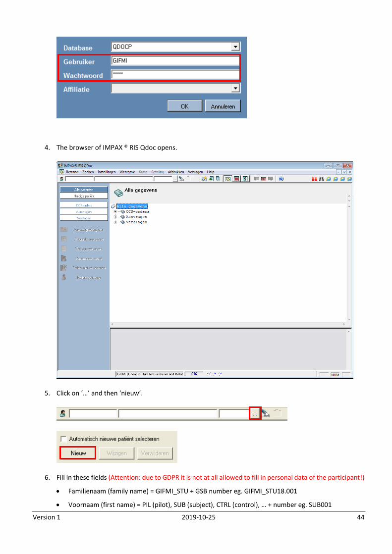
1. Start the personal computer (PC number UZ-11815). Auto log-in: no password or log-in needed.
2. Double-click on the desktop on the QDoc (shortcut).
3. Log in
Gebruiker: GIFMI (user name)
Wachtwoord: GIFMI (password)
Affiliatie: /
Version 1 2019-10-25 44
4. The browser of IMPAX ® RIS Qdoc opens.
5. Click on ‘…’ and then ‘nieuw’.
6. Fill in these fields (Attention: due to GDPR it is not at all allowed to fill in personal data of the participant!)
Familienaam (family name) = GIFMI_STU + GSB number eg. GIFMI_STU18.001
Voornaam (first name) = PIL (pilot), SUB (subject), CTRL (control), … + number eg. SUB001
Version 1 2019-10-25 45
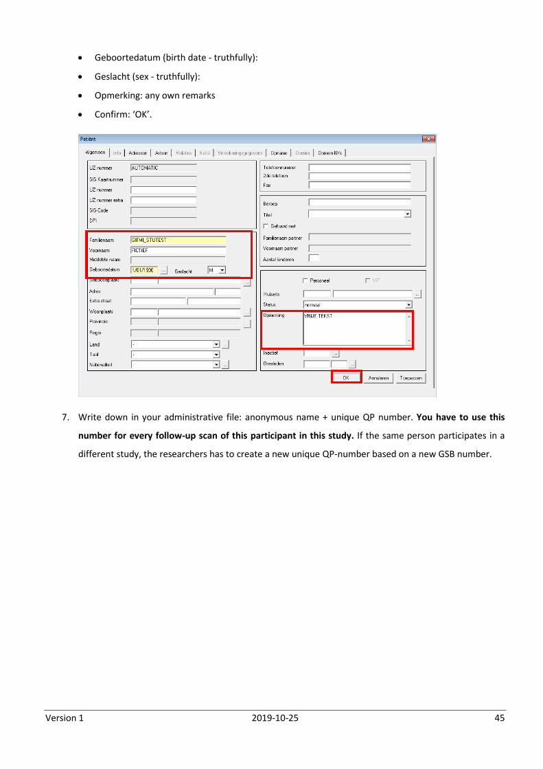
Geboortedatum (birth date - truthfully):
Geslacht (sex - truthfully):
Opmerking: any own remarks
Confirm: ‘OK’.
7. Write down in your administrative file: anonymous name + unique QP number. You have to use this
number for every follow-up scan of this participant in this study. If the same person participates in a
different study, the researchers has to create a new unique QP-number based on a new GSB number.
Version 1 2019-10-25 46
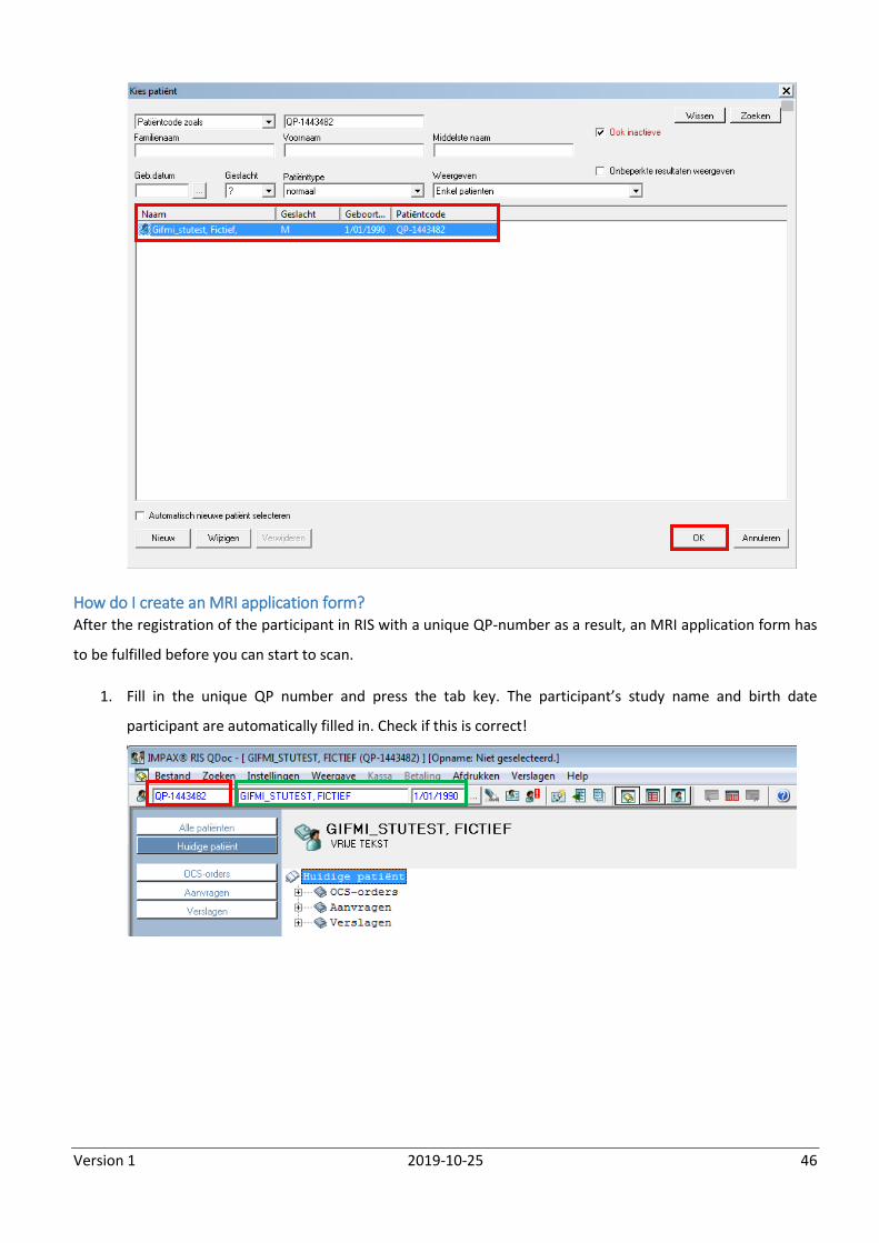
How do I create an MRI application form? After the registration of the participant in RIS with a unique QP-number as a result, an MRI application form has
to be fulfilled before you can start to scan.
1. Fill in the unique QP number and press the tab key. The participant’s study name and birth date
participant are automatically filled in. Check if this is correct!
Version 1 2019-10-25 47
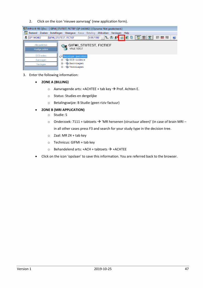
2. Click on the icon ‘nieuwe aanvraag’ (new application form).
3. Enter the following information:
ZONE A (BILLING)
o Aanvragende arts: +ACHTEE + tab key Prof. Achten E.
o Status: Studies en dergelijke
o Betalingswijze: B Studie (geen riziv factuur)
ZONE B (MRI APPLICATION)
o Studie: S
o Onderzoek: 7111 + tabtoets ‘MR hersenen (structuur alleen)’ (in case of brain MRI –
in all other cases press F3 and search for your study type in the decision tree.
o Zaal: MR Z4 + tab key
o Technicus: GIFMI + tab key
o Behandelend arts: +ACH + tabtoets +ACHTEE
Click on the icon ‘opslaan’ to save this information. You are referred back to the browser.
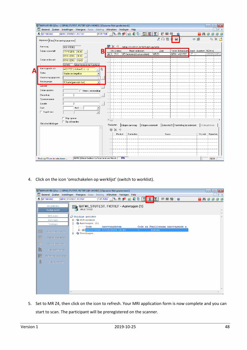
Version 1 2019-10-25 48
4. Click on the icon ‘omschakelen op werklijst’ (switch to worklist).
5. Set to MR Z4, then click on the icon to refresh. Your MRI application form is now complete and you can
start to scan. The participant will be preregistered on the scanner.
A
B

Version 1 2019-10-25 49
How do I retrieve the preregistered RIS form on the scanner? Since the participant is preregistered, there is no need to register participant data manually on the MRI console
as you used to.
1. Check Database
2. Double click on ‘Scheduler’ to refresh.
3. Double click in the third column (research type, in this case ‘MR hersenen’ (MR brain)).
4. Some data have already been entered based on the link with IMPAX® RIS QDoc. Fulfill the other
mandatory (bold) fields:
Height and weight
Patient Position (browse)
The button ‘Exam’ becomes active when the mandatory data are fulfilled. Click ‘Exam’.
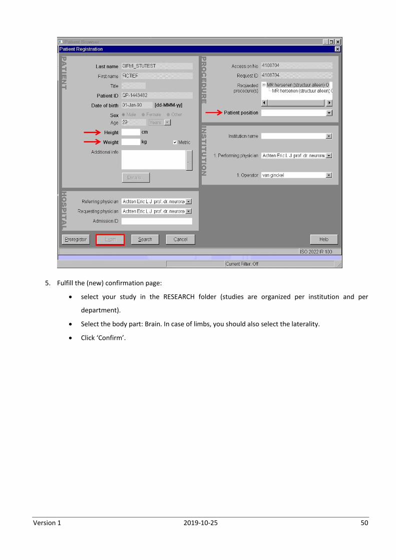
Version 1 2019-10-25 50
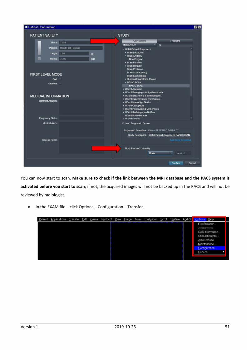
5. Fulfill the (new) confirmation page:
select your study in the RESEARCH folder (studies are organized per institution and per
department).
Select the body part: Brain. In case of limbs, you should also select the laterality.
Click ‘Confirm’.
Version 1 2019-10-25 51
You can now start to scan. Make sure to check if the link between the MRI database and the PACS system is
activated before you start to scan; if not, the acquired images will not be backed up in the PACS and will not be
reviewed by radiologist.
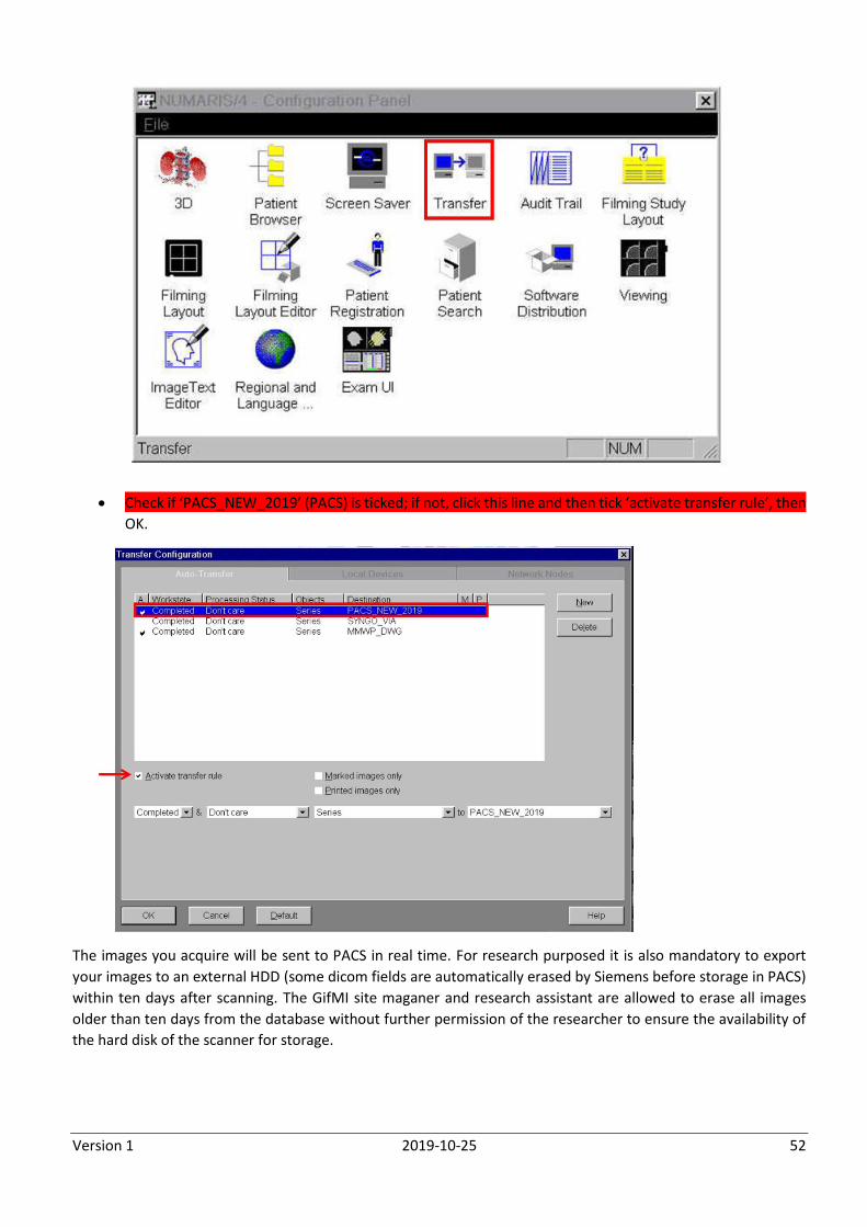
In the EXAM file – click Options – Configuration – Transfer.
Version 1 2019-10-25 52
Check if ‘PACS_NEW_2019’ (PACS) is ticked; if not, click this line and then tick ‘activate transfer rule’, then
OK.
The images you acquire will be sent to PACS in real time. For research purposed it is also mandatory to export
your images to an external HDD (some dicom fields are automatically erased by Siemens before storage in PACS)
within ten days after scanning. The GifMI site maganer and research assistant are allowed to erase all images
older than ten days from the database without further permission of the researcher to ensure the availability of
the hard disk of the scanner for storage.
Version 1 2019-10-25 53
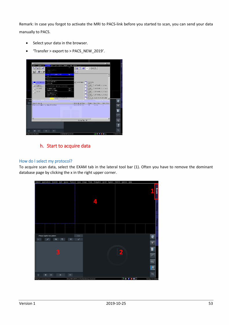
Remark: In case you forgot to activate the MRI to PACS-link before you started to scan, you can send your data
manually to PACS.
Select your data in the browser.
‘Transfer > export to > PACS_NEW_2019’.
h. Start to acquire data
How do I select my protocol? To acquire scan data, select the EXAM tab in the lateral tool bar (1). Often you have to remove the dominant
database page by clicking the x in the right upper corner.
Version 1 2019-10-25 54
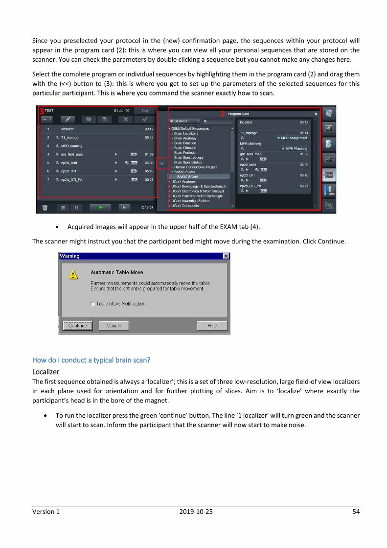
Since you preselected your protocol in the (new) confirmation page, the sequences within your protocol will
appear in the program card (2): this is where you can view all your personal sequences that are stored on the
scanner. You can check the parameters by double clicking a sequence but you cannot make any changes here.
Select the complete program or individual sequences by highlighting them in the program card (2) and drag them
with the (<<) button to (3): this is where you get to set-up the parameters of the selected sequences for this
particular participant. This is where you command the scanner exactly how to scan.
Acquired images will appear in the upper half of the EXAM tab (4).
The scanner might instruct you that the participant bed might move during the examination. Click Continue.
How do I conduct a typical brain scan?
Localizer The first sequence obtained is always a ‘localizer’; this is a set of three low-resolution, large field-of view localizers
in each plane used for orientation and for further plotting of slices. Aim is to ‘localize’ where exactly the
participant’s head is in the bore of the magnet.
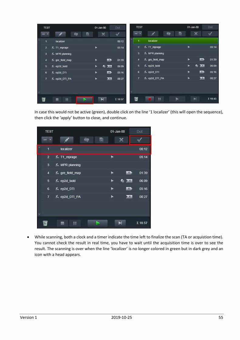
To run the localizer press the green ‘continue’ button. The line ‘1 localizer’ will turn green and the scanner
will start to scan. Inform the participant that the scanner will now start to make noise.
Version 1 2019-10-25 55
In case this would not be active (green), double click on the line ‘1 localizer’ (this will open the sequence),
then click the ‘apply’ button to close, and continue.
While scanning, both a clock and a timer indicate the time left to finalize the scan (TA or acquistion time).
You cannot check the result in real time, you have to wait until the acquisition time is over to see the
result. The scanning is over when the line ‘localizer’ is no longer colored in green but in dark grey and an
icon with a head appears.
Version 1 2019-10-25 56
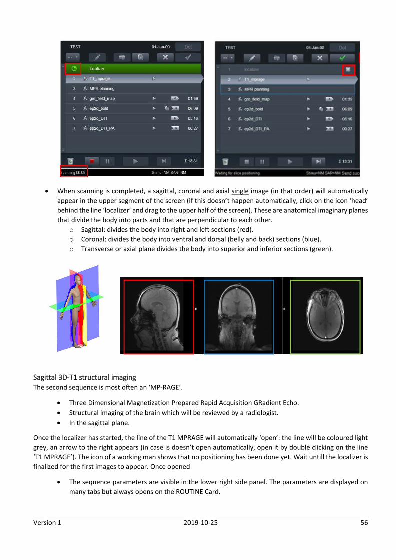
When scanning is completed, a sagittal, coronal and axial single image (in that order) will automatically
appear in the upper segment of the screen (if this doesn’t happen automatically, click on the icon ‘head’
behind the line ‘localizer’ and drag to the upper half of the screen). These are anatomical imaginary planes
that divide the body into parts and that are perpendicular to each other.
o Sagittal: divides the body into right and left sections (red).
o Coronal: divides the body into ventral and dorsal (belly and back) sections (blue).
o Transverse or axial plane divides the body into superior and inferior sections (green).
Sagittal 3D-T1 structural imaging The second sequence is most often an ‘MP-RAGE’.
Three Dimensional Magnetization Prepared Rapid Acquisition GRadient Echo.
Structural imaging of the brain which will be reviewed by a radiologist.
In the sagittal plane.
Once the localizer has started, the line of the T1 MPRAGE will automatically ‘open’: the line will be coloured light
grey, an arrow to the right appears (in case is doesn’t open automatically, open it by double clicking on the line
‘T1 MPRAGE’). The icon of a working man shows that no positioning has been done yet. Wait untill the localizer is
finalized for the first images to appear. Once opened
The sequence parameters are visible in the lower right side panel. The parameters are displayed on
many tabs but always opens on the ROUTINE Card.
Version 1 2019-10-25 57
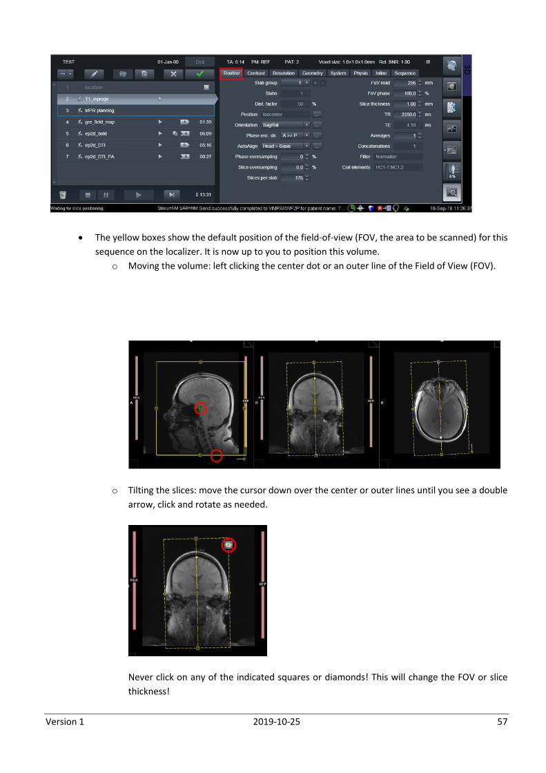
The yellow boxes show the default position of the field-of-view (FOV, the area to be scanned) for this
sequence on the localizer. It is now up to you to position this volume.
o Moving the volume: left clicking the center dot or an outer line of the Field of View (FOV).
o Tilting the slices: move the cursor down over the center or outer lines until you see a double
arrow, click and rotate as needed.
Never click on any of the indicated squares or diamonds! This will change the FOV or slice
thickness!
Version 1 2019-10-25 58
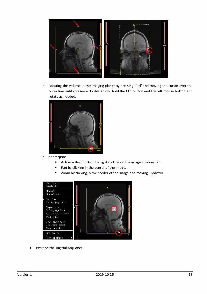
o Rotating the volume in the imaging plane: by pressing ‘Ctrl’ and moving the cursor over the
outer line until you see a double arrow; hold the Ctrl button and the left mouse button and
rotate as needed.
o Zoom/pan:
Activate this function by right clicking on the image > zoom/pan.
Pan by clicking in the center of the image.
Zoom by clicking in the border of the image and moving up/down.
Position the sagittal sequence:
Version 1 2019-10-25 59
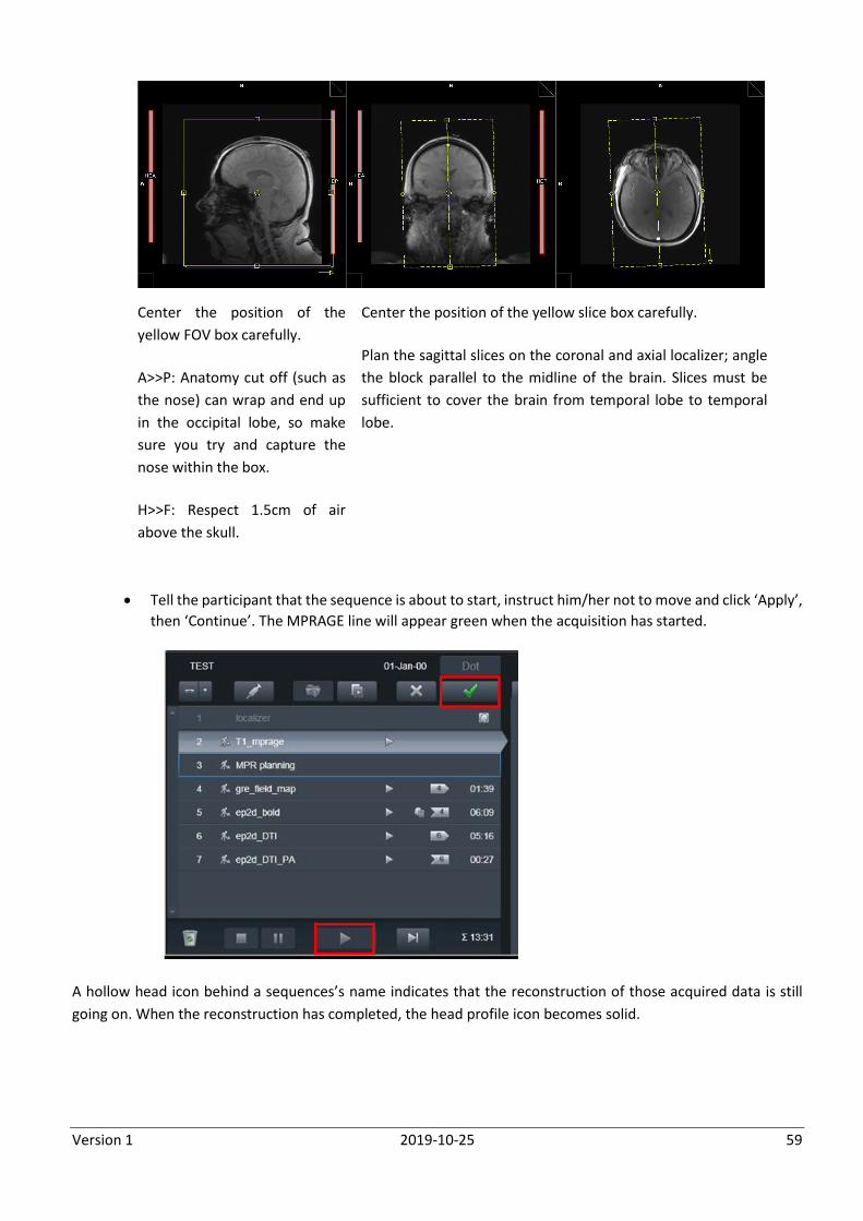
Center the position of the
yellow FOV box carefully.
A>>P: Anatomy cut off (such as
the nose) can wrap and end up
in the occipital lobe, so make
sure you try and capture the
nose within the box.
H>>F: Respect 1.5cm of air
above the skull.
Center the position of the yellow slice box carefully.
Plan the sagittal slices on the coronal and axial localizer; angle
the block parallel to the midline of the brain. Slices must be
sufficient to cover the brain from temporal lobe to temporal
lobe.
Tell the participant that the sequence is about to start, instruct him/her not to move and click ‘Apply’,
then ‘Continue’. The MPRAGE line will appear green when the acquisition has started.
A hollow head icon behind a sequences’s name indicates that the reconstruction of those acquired data is still
going on. When the reconstruction has completed, the head profile icon becomes solid.
Version 1 2019-10-25 60
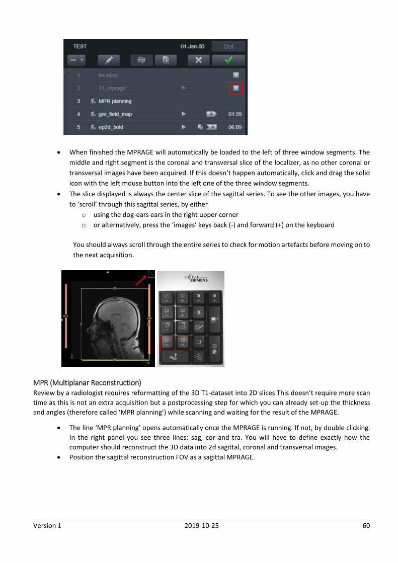
When finished the MPRAGE will automatically be loaded to the left of three window segments. The
middle and right segment is the coronal and transversal slice of the localizer, as no other coronal or
transversal images have been acquired. If this doesn’t happen automatically, click and drag the solid
icon with the left mouse button into the left one of the three window segments.
The slice displayed is always the center slice of the sagittal series. To see the other images, you have
to ‘scroll’ through this sagittal series, by either
o using the dog-ears ears in the right upper corner
o or alternatively, press the ‘images’ keys back (-) and forward (+) on the keyboard
You should always scroll through the entire series to check for motion artefacts before moving on to
the next acquisition.
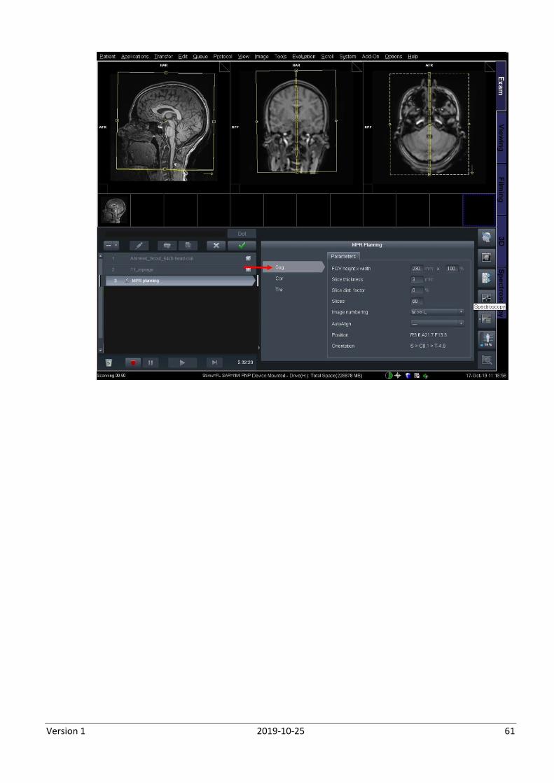
MPR (Multiplanar Reconstruction) Review by a radiologist requires reformatting of the 3D T1-dataset into 2D slices This doesn’t require more scan
time as this is not an extra acquisition but a postprocessing step for which you can already set-up the thickness
and angles (therefore called ‘MPR planning’) while scanning and waiting for the result of the MPRAGE.
The line ‘MPR planning’ opens automatically once the MPRAGE is running. If not, by double clicking.
In the right panel you see three lines: sag, cor and tra. You will have to define exactly how the
computer should reconstruct the 3D data into 2d sagittal, coronal and transversal images.
Position the sagittal reconstruction FOV as a sagittal MPRAGE.
Version 1 2019-10-25 61
Version 1 2019-10-25 62
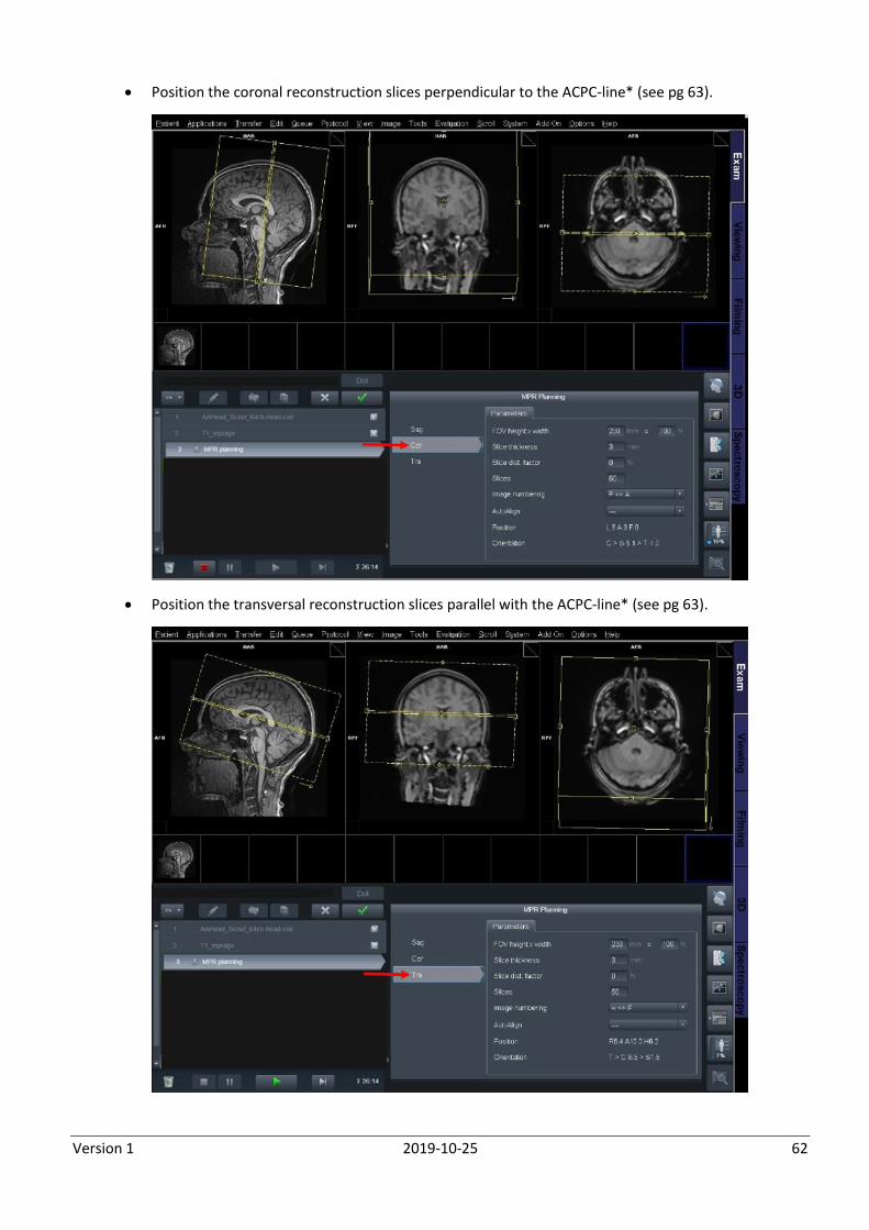
Position the coronal reconstruction slices perpendicular to the ACPC-line* (see pg 63).
Position the transversal reconstruction slices parallel with the ACPC-line* (see pg 63).
Version 1 2019-10-25 63
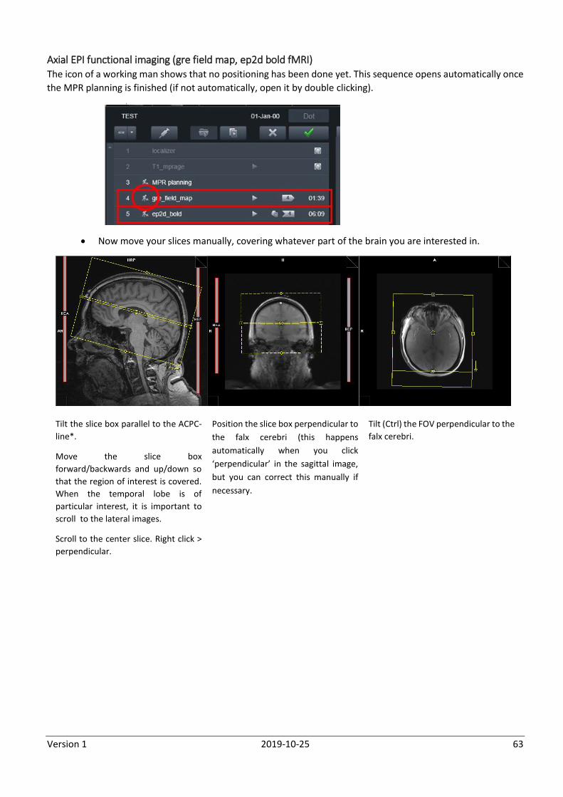
Axial EPI functional imaging (gre field map, ep2d bold fMRI) The icon of a working man shows that no positioning has been done yet. This sequence opens automatically once
the MPR planning is finished (if not automatically, open it by double clicking).
Now move your slices manually, covering whatever part of the brain you are interested in.
Tilt the slice box parallel to the ACPC-
line*.
Move the slice box
forward/backwards and up/down so
that the region of interest is covered.
When the temporal lobe is of
particular interest, it is important to
scroll to the lateral images.
Scroll to the center slice. Right click >
perpendicular.
Position the slice box perpendicular to
the falx cerebri (this happens
automatically when you click
‘perpendicular’ in the sagittal image,
but you can correct this manually if
necessary.
Tilt (Ctrl) the FOV perpendicular to the
falx cerebri.
Version 1 2019-10-25 64
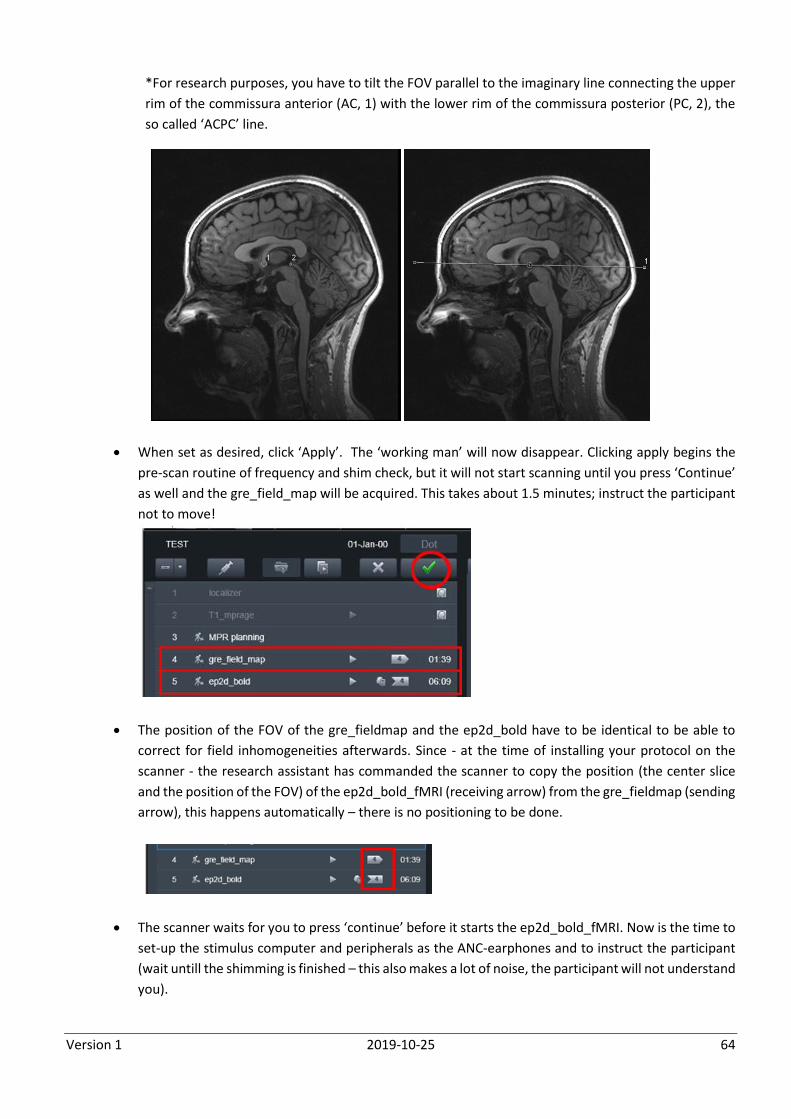
*For research purposes, you have to tilt the FOV parallel to the imaginary line connecting the upper
rim of the commissura anterior (AC, 1) with the lower rim of the commissura posterior (PC, 2), the
so called ‘ACPC’ line.
When set as desired, click ‘Apply’. The ‘working man’ will now disappear. Clicking apply begins the
pre-scan routine of frequency and shim check, but it will not start scanning until you press ‘Continue’
as well and the gre_field_map will be acquired. This takes about 1.5 minutes; instruct the participant
not to move!
The position of the FOV of the gre_fieldmap and the ep2d_bold have to be identical to be able to
correct for field inhomogeneities afterwards. Since - at the time of installing your protocol on the
scanner - the research assistant has commanded the scanner to copy the position (the center slice
and the position of the FOV) of the ep2d_bold_fMRI (receiving arrow) from the gre_fieldmap (sending
arrow), this happens automatically – there is no positioning to be done.
The scanner waits for you to press ‘continue’ before it starts the ep2d_bold_fMRI. Now is the time to
set-up the stimulus computer and peripherals as the ANC-earphones and to instruct the participant
(wait untill the shimming is finished – this also makes a lot of noise, the participant will not understand
you).
Version 1 2019-10-25 65
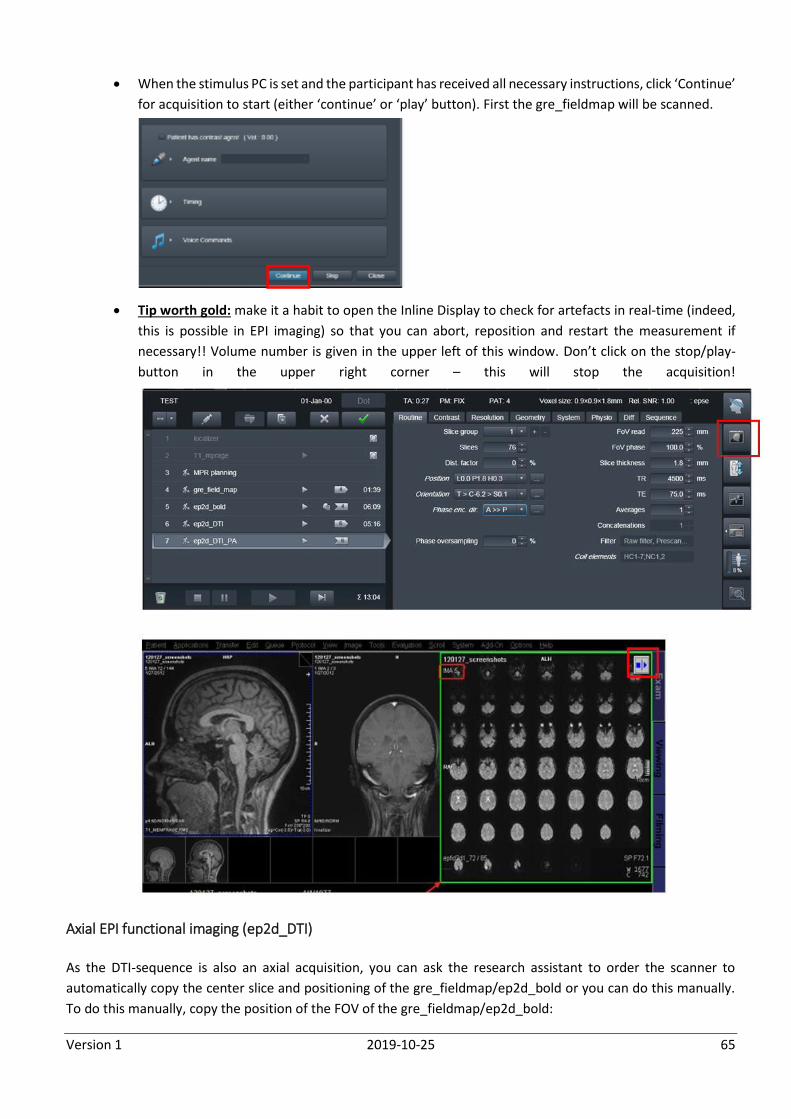
When the stimulus PC is set and the participant has received all necessary instructions, click ‘Continue’
for acquisition to start (either ‘continue’ or ‘play’ button). First the gre_fieldmap will be scanned.
Tip worth gold: make it a habit to open the Inline Display to check for artefacts in real-time (indeed,
this is possible in EPI imaging) so that you can abort, reposition and restart the measurement if
necessary!! Volume number is given in the upper left of this window. Don’t click on the stop/play-
button in the upper right corner – this will stop the acquisition!
Axial EPI functional imaging (ep2d_DTI)
As the DTI-sequence is also an axial acquisition, you can ask the research assistant to order the scanner to
automatically copy the center slice and positioning of the gre_fieldmap/ep2d_bold or you can do this manually.
To do this manually, copy the position of the FOV of the gre_fieldmap/ep2d_bold:
Version 1 2019-10-25 66
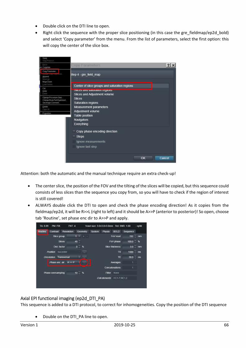
Double click on the DTI line to open.
Right click the sequence with the proper slice positioning (in this case the gre_fieldmap/ep2d_bold)
and select ‘Copy parameter’ from the menu. From the list of parameters, select the first option: this
will copy the center of the slice box.
Attention: both the automatic and the manual technique require an extra check-up!
The center slice, the position of the FOV and the tilting of the slices will be copied, but this sequence could
consists of less slices than the sequence you copy from, so you will have to check if the region of interest
is still covered!
ALWAYS double click the DTI to open and check the phase encoding direction! As it copies from the
fieldmap/ep2d, it will be R>>L (right to left) and it should be A>>P (anterior to posterior)! So open, choose
tab ‘Routine’, set phase enc dir to A>>P and apply.
Axial EPI functional imaging (ep2d_DTI_PA) This sequence is added to a DTI protocol, to correct for inhomogeneities. Copy the position of the DTI sequence
Double on the DTI_PA line to open.
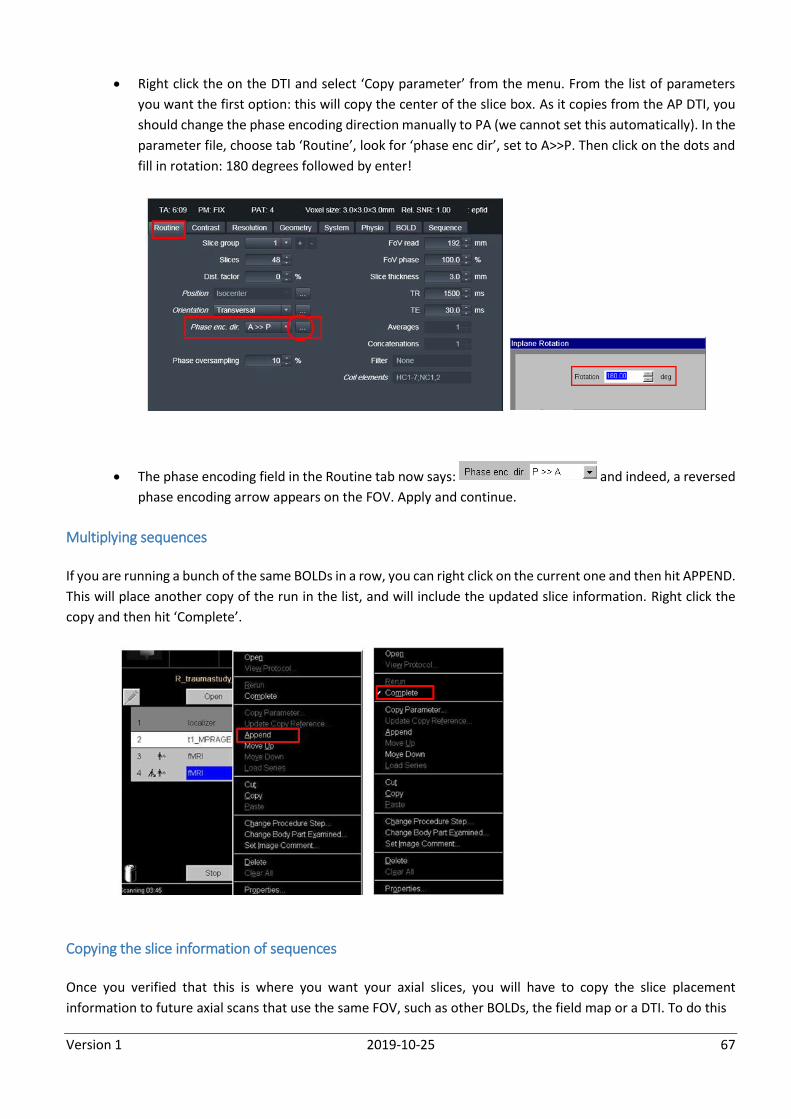
Version 1 2019-10-25 67
Right click the on the DTI and select ‘Copy parameter’ from the menu. From the list of parameters
you want the first option: this will copy the center of the slice box. As it copies from the AP DTI, you
should change the phase encoding direction manually to PA (we cannot set this automatically). In the
parameter file, choose tab ‘Routine’, look for ‘phase enc dir’, set to A>>P. Then click on the dots and
fill in rotation: 180 degrees followed by enter!
The phase encoding field in the Routine tab now says: and indeed, a reversed
phase encoding arrow appears on the FOV. Apply and continue.
Multiplying sequences
If you are running a bunch of the same BOLDs in a row, you can right click on the current one and then hit APPEND.
This will place another copy of the run in the list, and will include the updated slice information. Right click the
copy and then hit ‘Complete’.
Copying the slice information of sequences
Once you verified that this is where you want your axial slices, you will have to copy the slice placement
information to future axial scans that use the same FOV, such as other BOLDs, the field map or a DTI. To do this
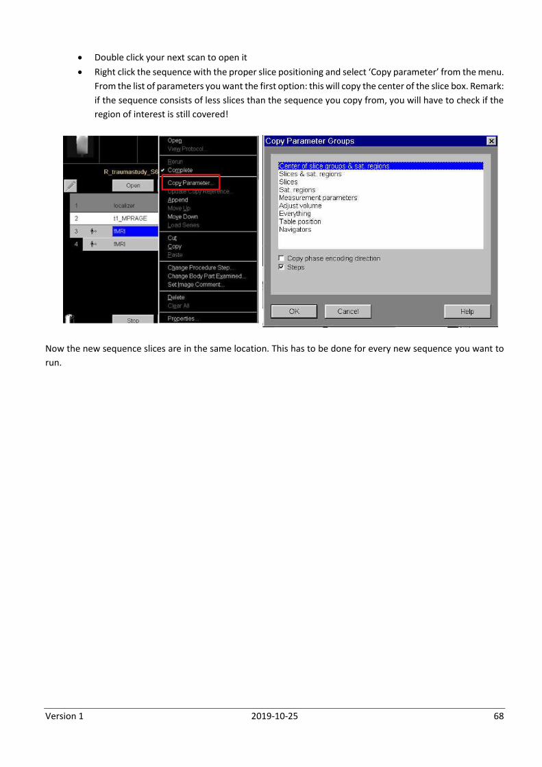
Version 1 2019-10-25 68
Double click your next scan to open it
Right click the sequence with the proper slice positioning and select ‘Copy parameter’ from the menu.
From the list of parameters you want the first option: this will copy the center of the slice box. Remark:
if the sequence consists of less slices than the sequence you copy from, you will have to check if the
region of interest is still covered!
Now the new sequence slices are in the same location. This has to be done for every new sequence you want to
run.
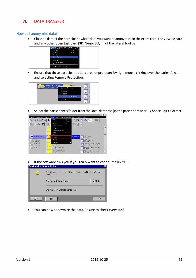
Version 1 2019-10-25 69
VI. DATA TRANSFER
How do I anonymize data?
Close all data of the participant who’s data you want to anonymize in the exam card, the viewing card
and any other open task card (3D, Neuro 3D, …) of the lateral tool bar.
Ensure that these participant’s data are not protected by right mouse clicking over the patient’s name
and selecting Remove Protection.
Select the participant’s folder from the local database (in the patient browser). Choose Edit > Correct.
If the software asks you if you really want to continue: click YES.
You can now anonymize the data. Ensure to check every tab!
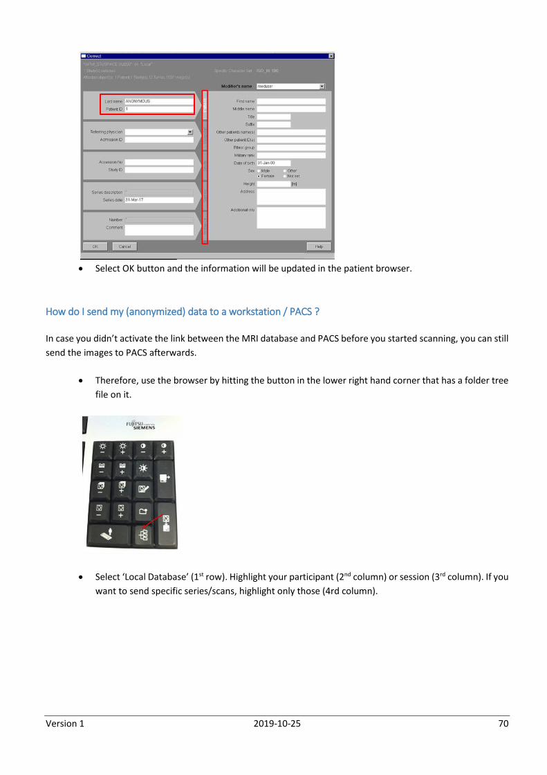
Version 1 2019-10-25 70
Select OK button and the information will be updated in the patient browser.
How do I send my (anonymized) data to a workstation / PACS ?
In case you didn’t activate the link between the MRI database and PACS before you started scanning, you can still
send the images to PACS afterwards.
Therefore, use the browser by hitting the button in the lower right hand corner that has a folder tree
file on it.
Select ‘Local Database’ (1st row). Highlight your participant (2nd column) or session (3rd column). If you
want to send specific series/scans, highlight only those (4rd column).
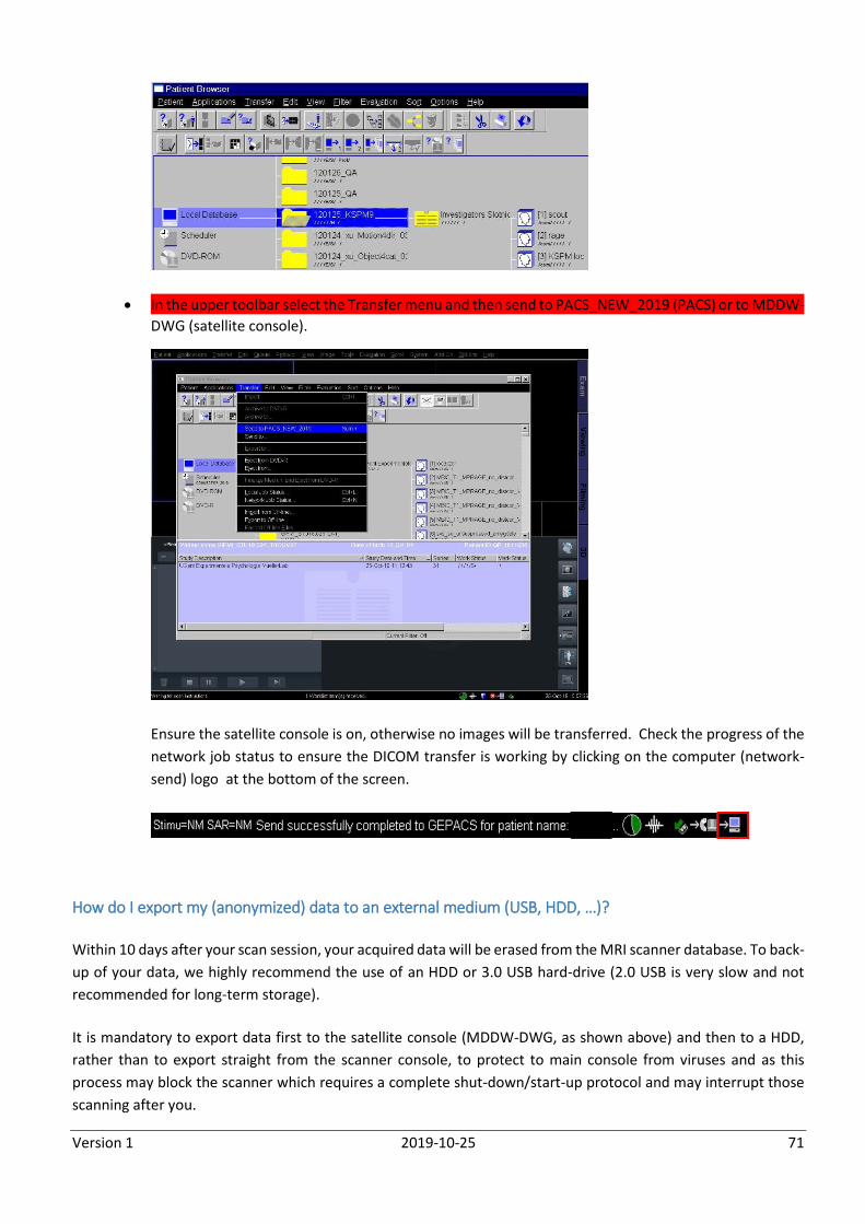
Version 1 2019-10-25 71
In the upper toolbar select the Transfer menu and then send to PACS_NEW_2019 (PACS) or to MDDW-
DWG (satellite console).
Ensure the satellite console is on, otherwise no images will be transferred. Check the progress of the
network job status to ensure the DICOM transfer is working by clicking on the computer (network-
send) logo at the bottom of the screen.
How do I export my (anonymized) data to an external medium (USB, HDD, …)?
Within 10 days after your scan session, your acquired data will be erased from the MRI scanner database. To back-
up of your data, we highly recommend the use of an HDD or 3.0 USB hard-drive (2.0 USB is very slow and not
recommended for long-term storage).
It is mandatory to export data first to the satellite console (MDDW-DWG, as shown above) and then to a HDD,
rather than to export straight from the scanner console, to protect to main console from viruses and as this
process may block the scanner which requires a complete shut-down/start-up protocol and may interrupt those
scanning after you.
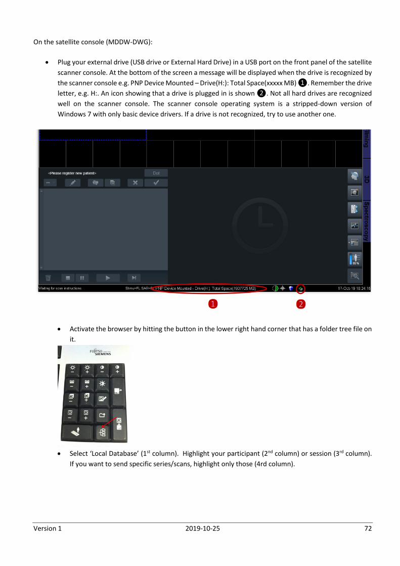
Version 1 2019-10-25 72
On the satellite console (MDDW-DWG):
Plug your external drive (USB drive or External Hard Drive) in a USB port on the front panel of the satellite
scanner console. At the bottom of the screen a message will be displayed when the drive is recognized by
the scanner console e.g. PNP Device Mounted – Drive(H:): Total Space(xxxxx MB) ❶. Remember the drive
letter, e.g. H:. An icon showing that a drive is plugged in is shown ❷. Not all hard drives are recognized
well on the scanner console. The scanner console operating system is a stripped-down version of
Windows 7 with only basic device drivers. If a drive is not recognized, try to use another one.
Activate the browser by hitting the button in the lower right hand corner that has a folder tree file on
it.
Select ‘Local Database’ (1st column). Highlight your participant (2nd column) or session (3rd column).
If you want to send specific series/scans, highlight only those (4rd column).
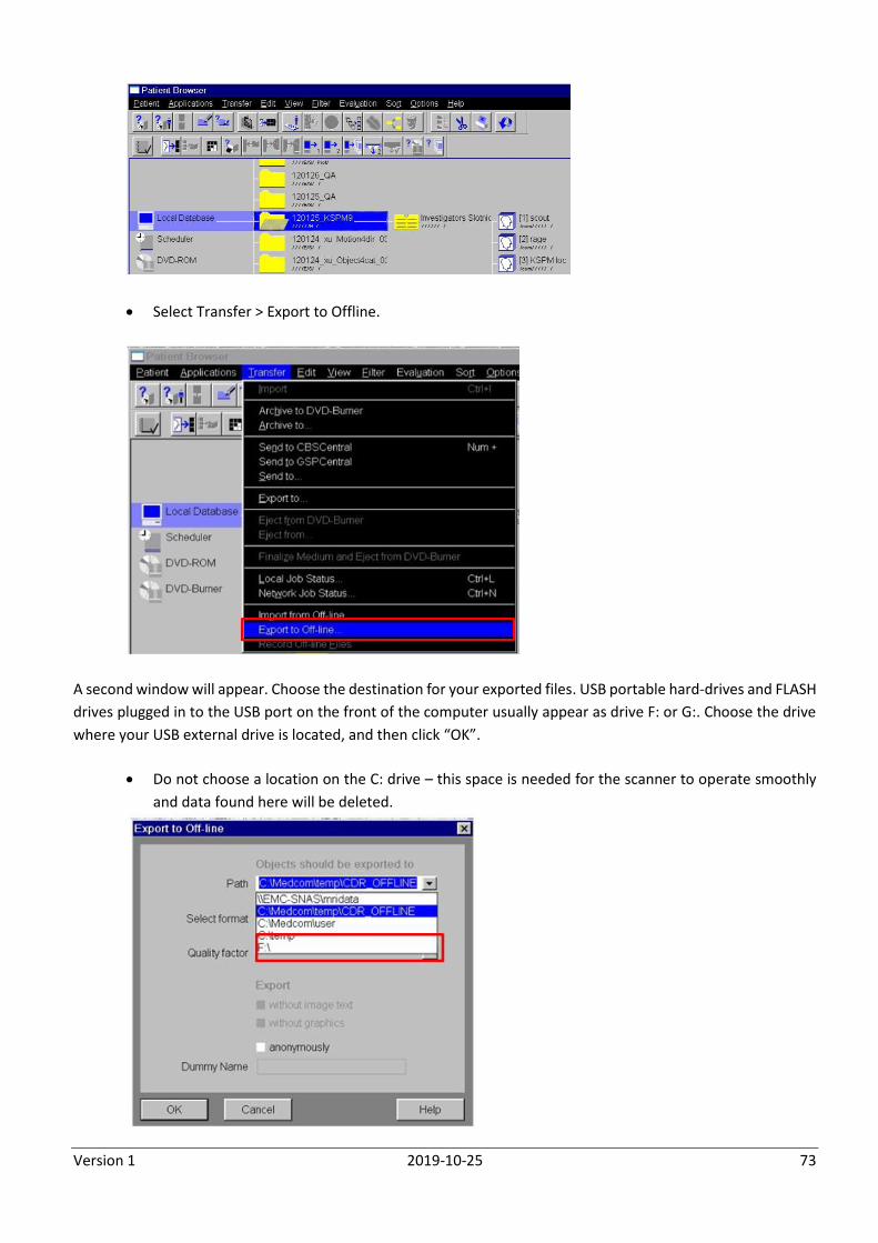
Version 1 2019-10-25 73
Select Transfer > Export to Offline.
A second window will appear. Choose the destination for your exported files. USB portable hard-drives and FLASH
drives plugged in to the USB port on the front of the computer usually appear as drive F: or G:. Choose the drive
where your USB external drive is located, and then click “OK”.
Do not choose a location on the C: drive – this space is needed for the scanner to operate smoothly
and data found here will be deleted.
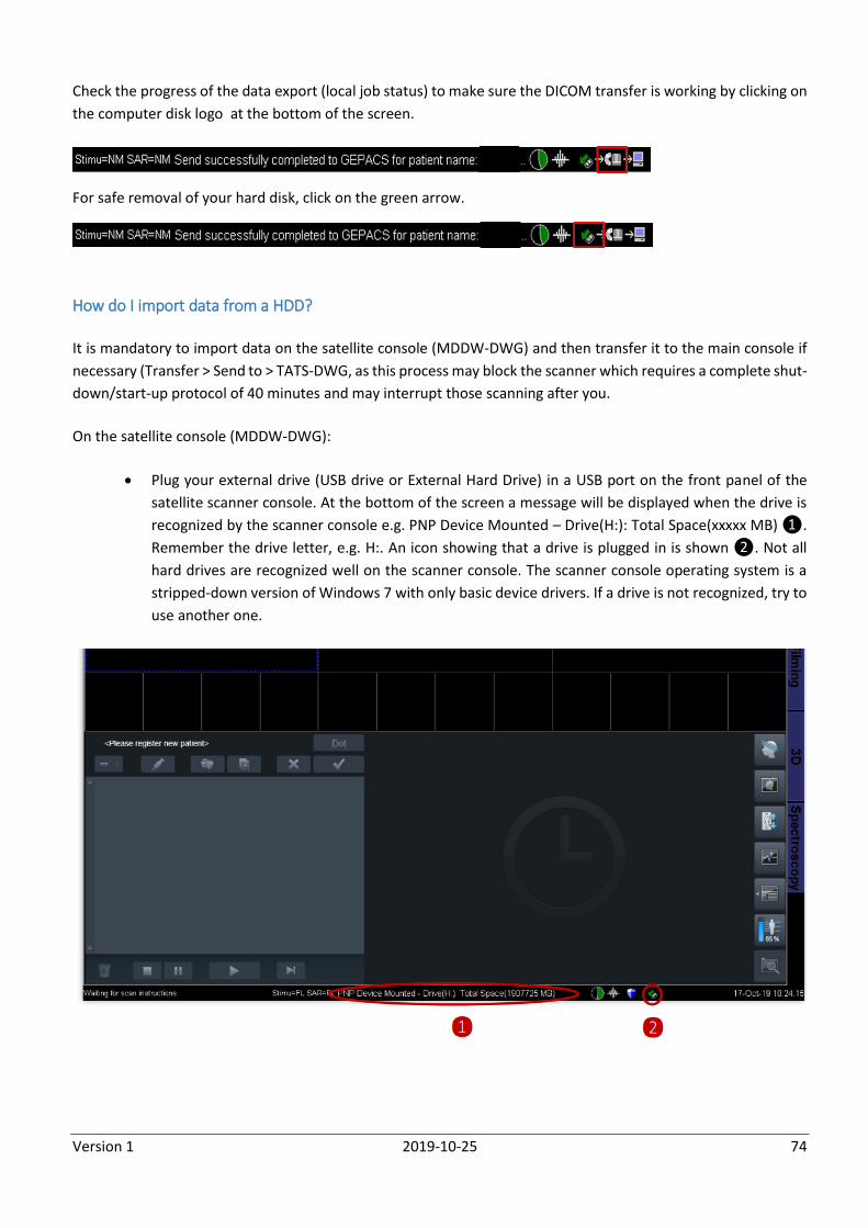
Version 1 2019-10-25 74
Check the progress of the data export (local job status) to make sure the DICOM transfer is working by clicking on
the computer disk logo at the bottom of the screen.
For safe removal of your hard disk, click on the green arrow.
How do I import data from a HDD?
It is mandatory to import data on the satellite console (MDDW-DWG) and then transfer it to the main console if
necessary (Transfer > Send to > TATS-DWG, as this process may block the scanner which requires a complete shut-
down/start-up protocol of 40 minutes and may interrupt those scanning after you.
On the satellite console (MDDW-DWG):
Plug your external drive (USB drive or External Hard Drive) in a USB port on the front panel of the
satellite scanner console. At the bottom of the screen a message will be displayed when the drive is
recognized by the scanner console e.g. PNP Device Mounted – Drive(H:): Total Space(xxxxx MB) ❶.
Remember the drive letter, e.g. H:. An icon showing that a drive is plugged in is shown ❷. Not all
hard drives are recognized well on the scanner console. The scanner console operating system is a
stripped-down version of Windows 7 with only basic device drivers. If a drive is not recognized, try to
use another one.
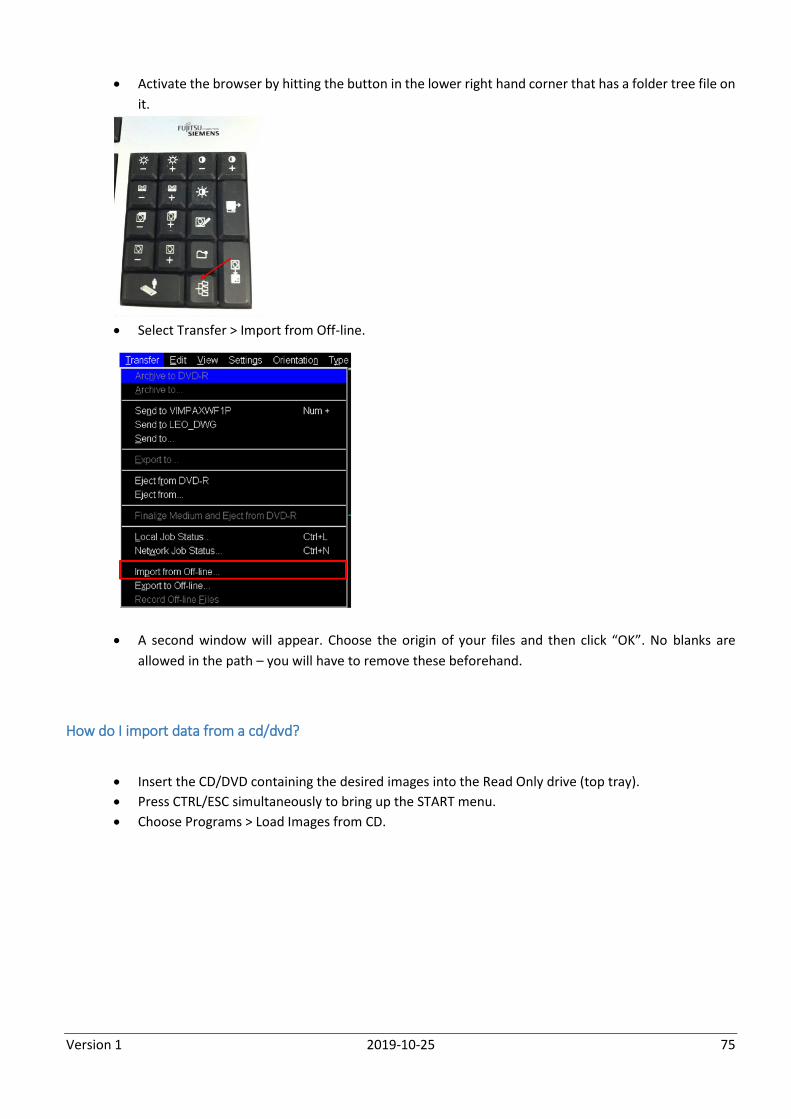
Version 1 2019-10-25 75
Activate the browser by hitting the button in the lower right hand corner that has a folder tree file on
it.
Select Transfer > Import from Off-line.
A second window will appear. Choose the origin of your files and then click “OK”. No blanks are
allowed in the path – you will have to remove these beforehand.
How do I import data from a cd/dvd?
Insert the CD/DVD containing the desired images into the Read Only drive (top tray).
Press CTRL/ESC simultaneously to bring up the START menu.
Choose Programs > Load Images from CD.
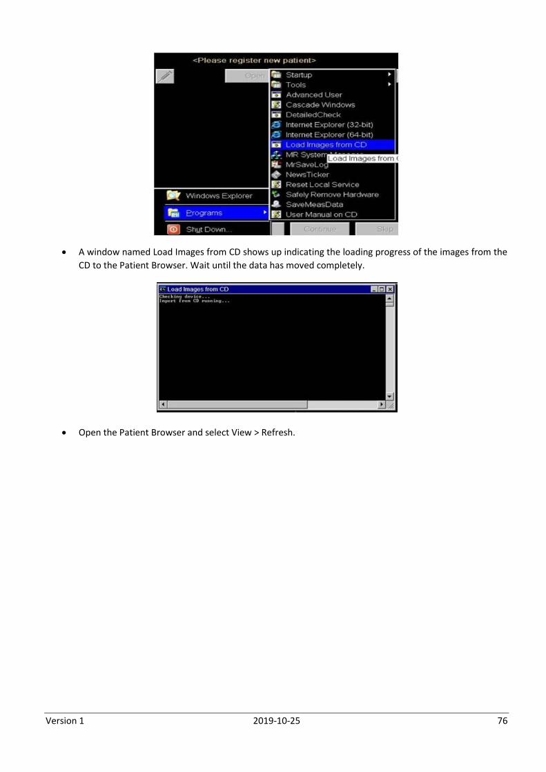
Version 1 2019-10-25 76
A window named Load Images from CD shows up indicating the loading progress of the images from the
CD to the Patient Browser. Wait until the data has moved completely.
Open the Patient Browser and select View > Refresh.
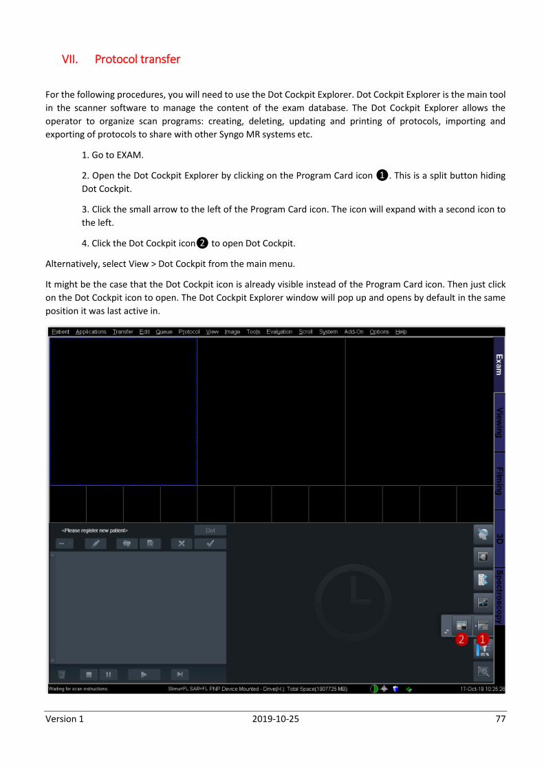
Version 1 2019-10-25 77
VII. Protocol transfer
For the following procedures, you will need to use the Dot Cockpit Explorer. Dot Cockpit Explorer is the main tool
in the scanner software to manage the content of the exam database. The Dot Cockpit Explorer allows the
operator to organize scan programs: creating, deleting, updating and printing of protocols, importing and
exporting of protocols to share with other Syngo MR systems etc.
1. Go to EXAM.
2. Open the Dot Cockpit Explorer by clicking on the Program Card icon ❶. This is a split button hiding
Dot Cockpit.
3. Click the small arrow to the left of the Program Card icon. The icon will expand with a second icon to
the left.
4. Click the Dot Cockpit icon❷ to open Dot Cockpit.
Alternatively, select View > Dot Cockpit from the main menu.
It might be the case that the Dot Cockpit icon is already visible instead of the Program Card icon. Then just click
on the Dot Cockpit icon to open. The Dot Cockpit Explorer window will pop up and opens by default in the same
position it was last active in.
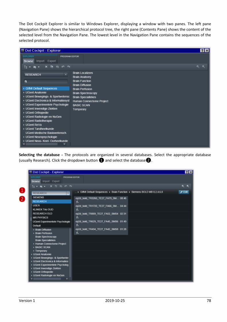
Version 1 2019-10-25 78
The Dot Cockpit Explorer is similar to Windows Explorer, displaying a window with two panes. The left pane
(Navigation Pane) shows the hierarchical protocol tree, the right pane (Contents Pane) shows the content of the
selected level from the Navigation Pane. The lowest level in the Navigation Pane contains the sequences of the
selected protocol.
Selecting the database - The protocols are organized in several databases. Select the appropriate database
(usually Research). Click the dropdown button ❶ and select the database❷.
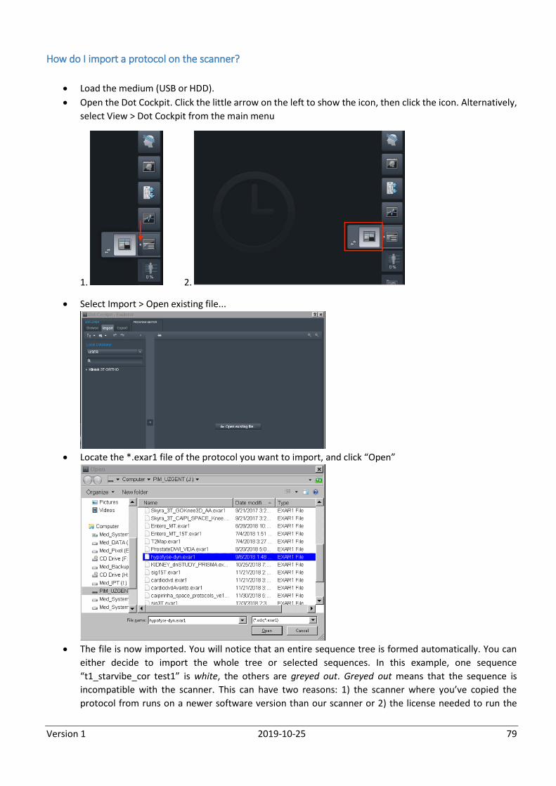
Version 1 2019-10-25 79
How do I import a protocol on the scanner?
Load the medium (USB or HDD).
Open the Dot Cockpit. Click the little arrow on the left to show the icon, then click the icon. Alternatively,
select View > Dot Cockpit from the main menu
1. 2.
Select Import > Open existing file...
Locate the *.exar1 file of the protocol you want to import, and click “Open”
The file is now imported. You will notice that an entire sequence tree is formed automatically. You can
either decide to import the whole tree or selected sequences. In this example, one sequence
“t1_starvibe_cor test1” is white, the others are greyed out. Greyed out means that the sequence is
incompatible with the scanner. This can have two reasons: 1) the scanner where you’ve copied the
protocol from runs on a newer software version than our scanner or 2) the license needed to run the
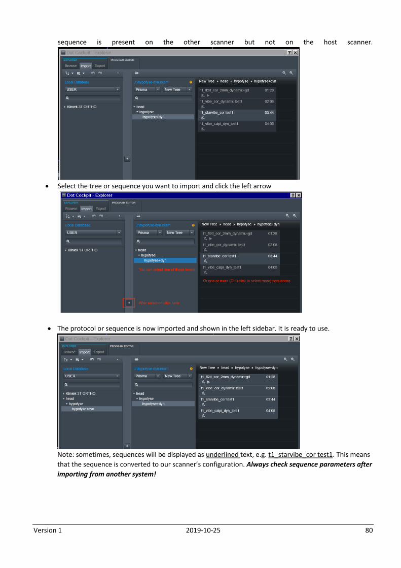
Version 1 2019-10-25 80
sequence is present on the other scanner but not on the host scanner.
Select the tree or sequence you want to import and click the left arrow
The protocol or sequence is now imported and shown in the left sidebar. It is ready to use.
Note: sometimes, sequences will be displayed as underlined text, e.g. t1_starvibe_cor test1. This means
that the sequence is converted to our scanner’s configuration. Always check sequence parameters after
importing from another system!
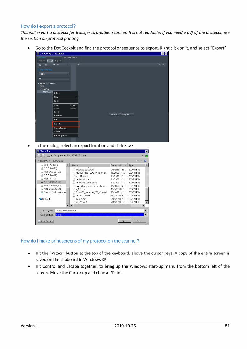
Version 1 2019-10-25 81
How do I export a protocol? This will export a protocol for transfer to another scanner. It is not readable! If you need a pdf of the protocol, see
the section on protocol printing.
Go to the Dot Cockpit and find the protocol or sequence to export. Right click on it, and select “Export”
In the dialog, select an export location and click Save
How do I make print screens of my protocol on the scanner?
Hit the "PrtScr" button at the top of the keyboard, above the cursor keys. A copy of the entire screen is
saved on the clipboard in Windows XP.
Hit Control and Escape together, to bring up the Windows start-up menu from the bottom left of the
screen. Move the Cursor up and choose "Paint".
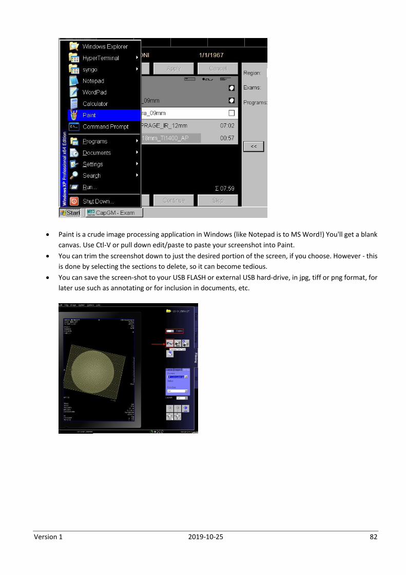
Version 1 2019-10-25 82
Paint is a crude image processing application in Windows (like Notepad is to MS Word!) You'll get a blank
canvas. Use Ctl-V or pull down edit/paste to paste your screenshot into Paint.
You can trim the screenshot down to just the desired portion of the screen, if you choose. However - this
is done by selecting the sections to delete, so it can become tedious.
You can save the screen-shot to your USB FLASH or external USB hard-drive, in jpg, tiff or png format, for
later use such as annotating or for inclusion in documents, etc.
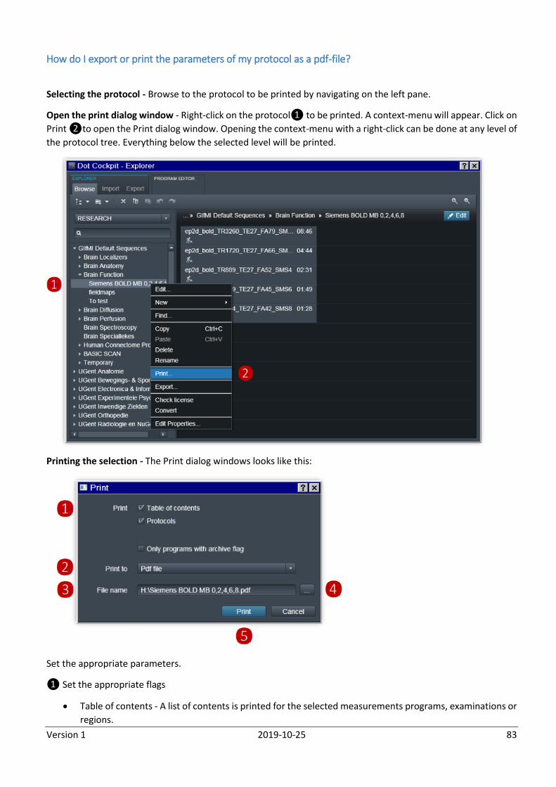
Version 1 2019-10-25 83
How do I export or print the parameters of my protocol as a pdf-file?
Selecting the protocol - Browse to the protocol to be printed by navigating on the left pane.
Open the print dialog window - Right-click on the protocol❶ to be printed. A context-menu will appear. Click on
Print ❷to open the Print dialog window. Opening the context-menu with a right-click can be done at any level of
the protocol tree. Everything below the selected level will be printed.
Printing the selection - The Print dialog windows looks like this:
Set the appropriate parameters.
❶ Set the appropriate flags
Table of contents - A list of contents is printed for the selected measurements programs, examinations or
regions.
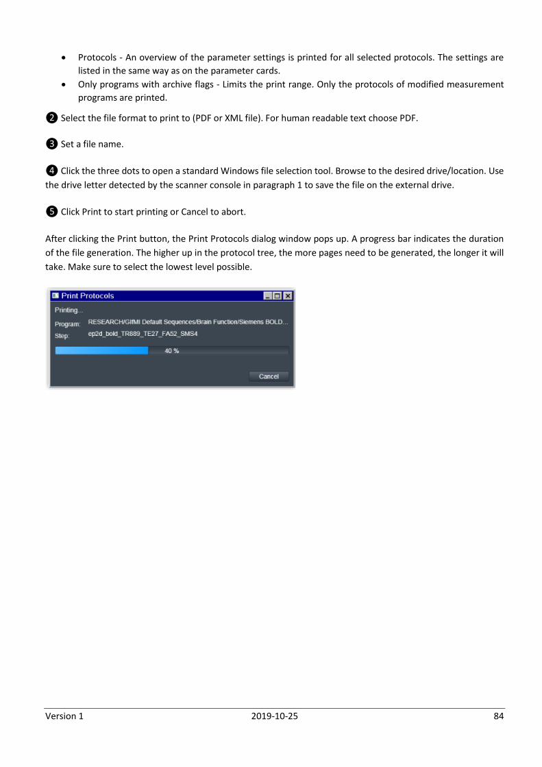
Version 1 2019-10-25 84
Protocols - An overview of the parameter settings is printed for all selected protocols. The settings are
listed in the same way as on the parameter cards.
Only programs with archive flags - Limits the print range. Only the protocols of modified measurement
programs are printed.
❷ Select the file format to print to (PDF or XML file). For human readable text choose PDF.
❸ Set a file name.
❹ Click the three dots to open a standard Windows file selection tool. Browse to the desired drive/location. Use
the drive letter detected by the scanner console in paragraph 1 to save the file on the external drive.
❺ Click Print to start printing or Cancel to abort.
After clicking the Print button, the Print Protocols dialog window pops up. A progress bar indicates the duration
of the file generation. The higher up in the protocol tree, the more pages need to be generated, the longer it will
take. Make sure to select the lowest level possible.
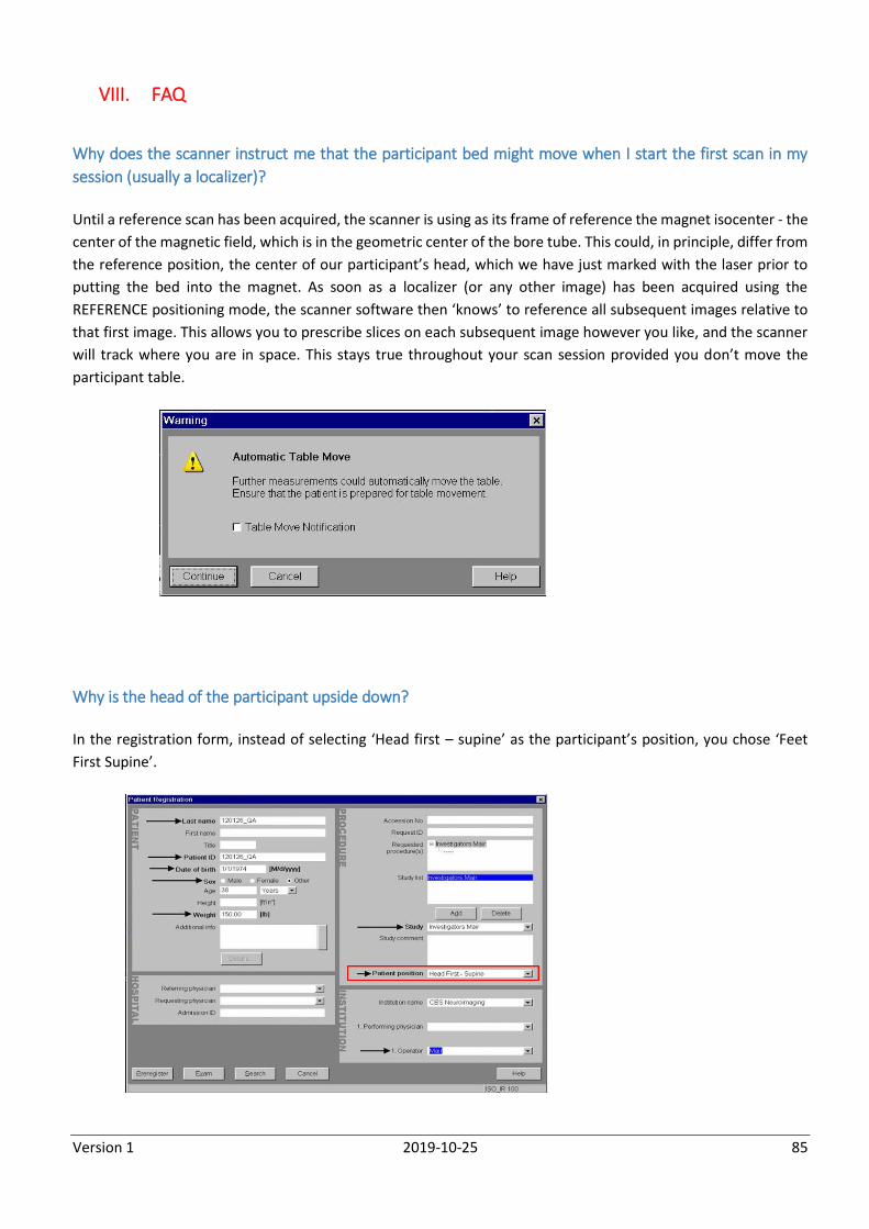
Version 1 2019-10-25 85
VIII. FAQ
Why does the scanner instruct me that the participant bed might move when I start the first scan in my
session (usually a localizer)?
Until a reference scan has been acquired, the scanner is using as its frame of reference the magnet isocenter - the
center of the magnetic field, which is in the geometric center of the bore tube. This could, in principle, differ from
the reference position, the center of our participant’s head, which we have just marked with the laser prior to
putting the bed into the magnet. As soon as a localizer (or any other image) has been acquired using the
REFERENCE positioning mode, the scanner software then ‘knows’ to reference all subsequent images relative to
that first image. This allows you to prescribe slices on each subsequent image however you like, and the scanner
will track where you are in space. This stays true throughout your scan session provided you don’t move the
participant table.
Why is the head of the participant upside down?
In the registration form, instead of selecting ‘Head first – supine’ as the participant’s position, you chose ‘Feet
First Supine’.
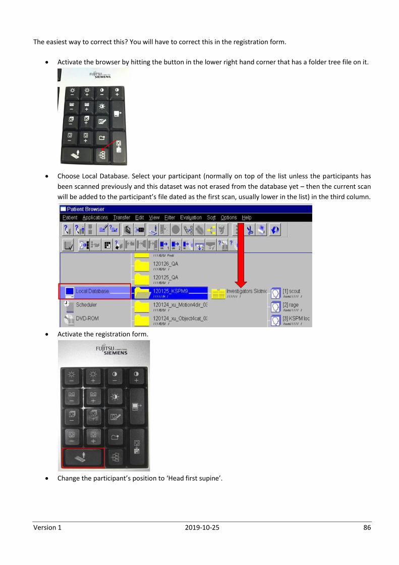
Version 1 2019-10-25 86
The easiest way to correct this? You will have to correct this in the registration form.
Activate the browser by hitting the button in the lower right hand corner that has a folder tree file on it.
Choose Local Database. Select your participant (normally on top of the list unless the participants has
been scanned previously and this dataset was not erased from the database yet – then the current scan
will be added to the participant’s file dated as the first scan, usually lower in the list) in the third column.
Activate the registration form.
Change the participant’s position to ‘Head first supine’.
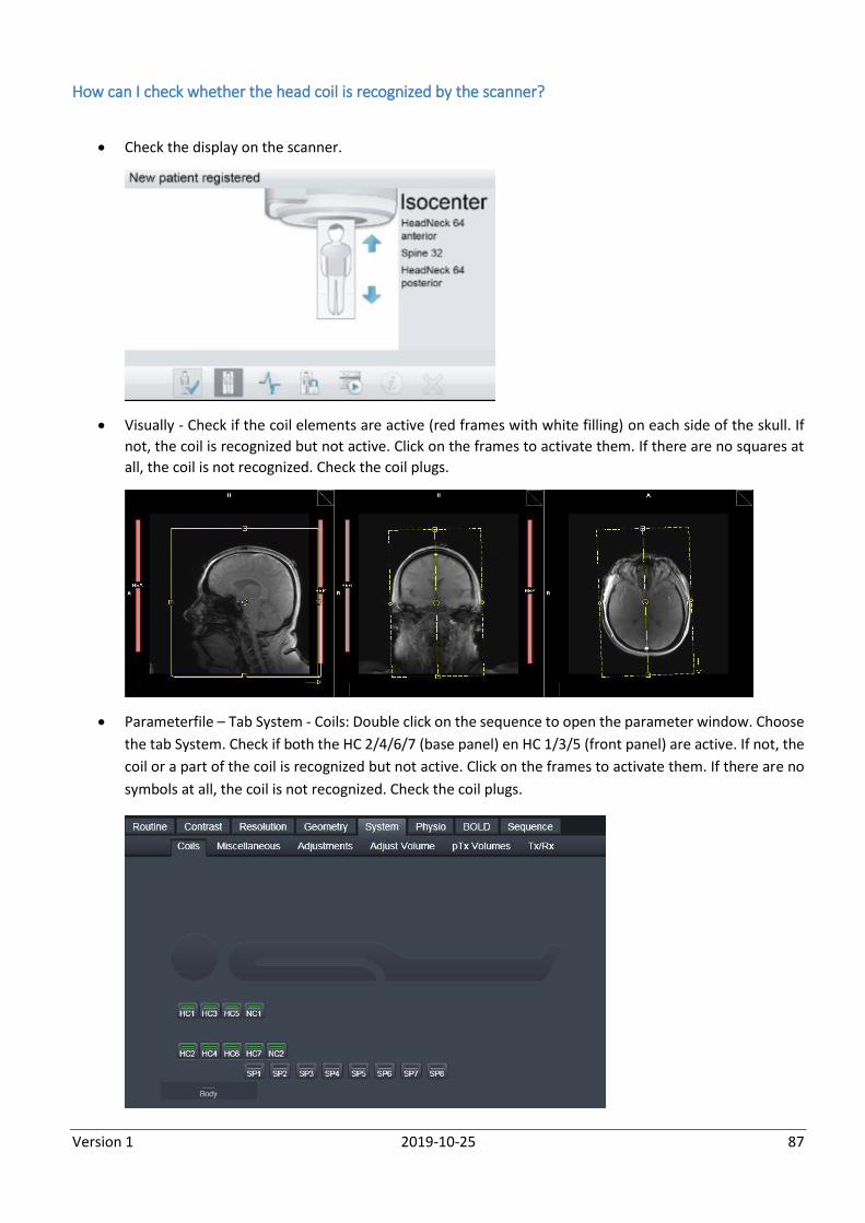
Version 1 2019-10-25 87
How can I check whether the head coil is recognized by the scanner?
Check the display on the scanner.
Visually - Check if the coil elements are active (red frames with white filling) on each side of the skull. If
not, the coil is recognized but not active. Click on the frames to activate them. If there are no squares at
all, the coil is not recognized. Check the coil plugs.
Parameterfile – Tab System - Coils: Double click on the sequence to open the parameter window. Choose
the tab System. Check if both the HC 2/4/6/7 (base panel) en HC 1/3/5 (front panel) are active. If not, the
coil or a part of the coil is recognized but not active. Click on the frames to activate them. If there are no
symbols at all, the coil is not recognized. Check the coil plugs.
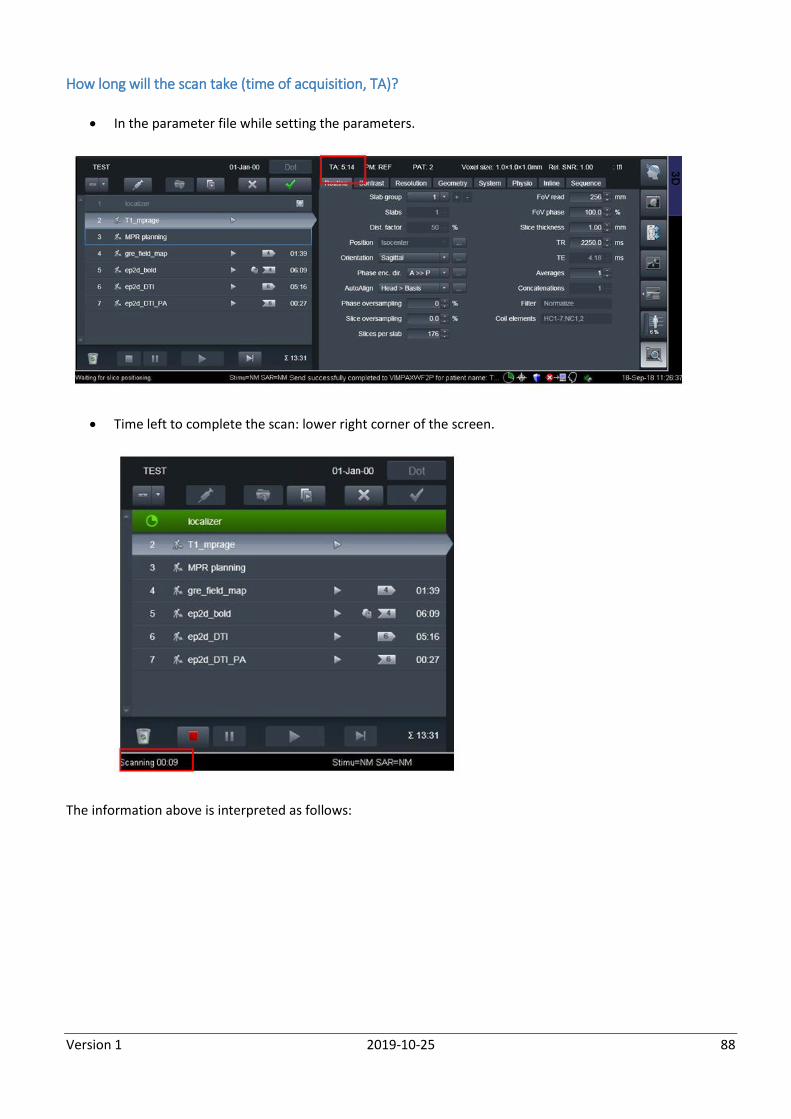
Version 1 2019-10-25 88
How long will the scan take (time of acquisition, TA)?
In the parameter file while setting the parameters.
Time left to complete the scan: lower right corner of the screen.
The information above is interpreted as follows:
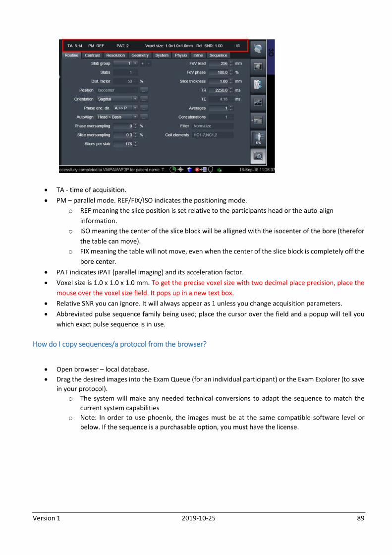
Version 1 2019-10-25 89
TA - time of acquisition.
PM – parallel mode. REF/FIX/ISO indicates the positioning mode.
o REF meaning the slice position is set relative to the participants head or the auto-align
information.
o ISO meaning the center of the slice block will be alligned with the isocenter of the bore (therefor
the table can move).
o FIX meaning the table will not move, even when the center of the slice block is completely off the
bore center.
PAT indicates iPAT (parallel imaging) and its acceleration factor.
Voxel size is 1.0 x 1.0 x 1.0 mm. To get the precise voxel size with two decimal place precision, place the
mouse over the voxel size field. It pops up in a new text box.
Relative SNR you can ignore. It will always appear as 1 unless you change acquisition parameters.
Abbreviated pulse sequence family being used; place the cursor over the field and a popup will tell you
which exact pulse sequence is in use.
How do I copy sequences/a protocol from the browser?
Open browser – local database.
Drag the desired images into the Exam Queue (for an individual participant) or the Exam Explorer (to save
in your protocol).
o The system will make any needed technical conversions to adapt the sequence to match the
current system capabilities
o Note: In order to use phoenix, the images must be at the same compatible software level or
below. If the sequence is a purchasable option, you must have the license.
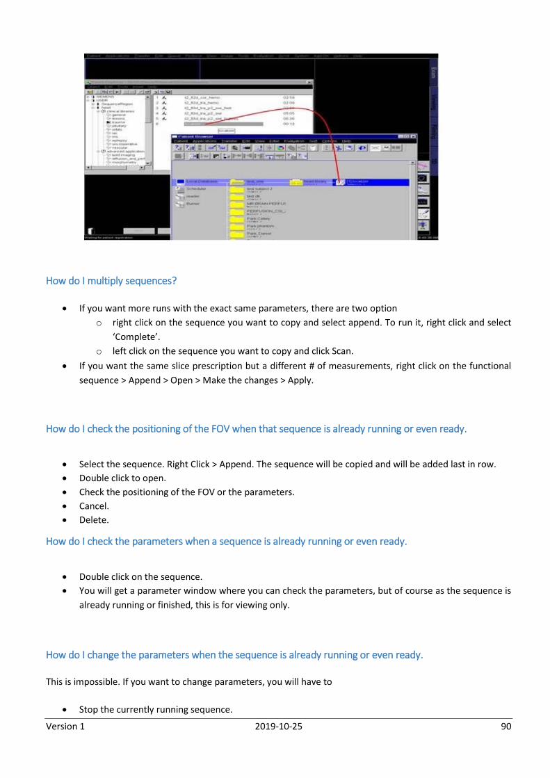
Version 1 2019-10-25 90
How do I multiply sequences?
If you want more runs with the exact same parameters, there are two option
o right click on the sequence you want to copy and select append. To run it, right click and select
‘Complete’.
o left click on the sequence you want to copy and click Scan.
If you want the same slice prescription but a different # of measurements, right click on the functional
sequence > Append > Open > Make the changes > Apply.
How do I check the positioning of the FOV when that sequence is already running or even ready.
Select the sequence. Right Click > Append. The sequence will be copied and will be added last in row.
Double click to open.
Check the positioning of the FOV or the parameters.
Cancel.
Delete.
How do I check the parameters when a sequence is already running or even ready.
Double click on the sequence.
You will get a parameter window where you can check the parameters, but of course as the sequence is
already running or finished, this is for viewing only.
How do I change the parameters when the sequence is already running or even ready.
This is impossible. If you want to change parameters, you will have to
Stop the currently running sequence.
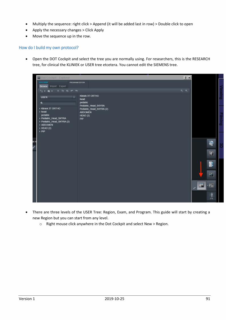
Version 1 2019-10-25 91
Multiply the sequence: right click > Append (it will be added last in row) > Double click to open
Apply the necessary changes > Click Apply
Move the sequence up in the row.
How do I build my own protocol?
Open the DOT Cockpit and select the tree you are normally using. For researchers, this is the RESEARCH
tree, for clinical the KLINIEK or USER tree etcetera. You cannot edit the SIEMENS tree.
There are three levels of the USER Tree: Region, Exam, and Program. This guide will start by creating a
new Region but you can start from any level.
o Right mouse click anywhere in the Dot Cockpit and select New > Region.
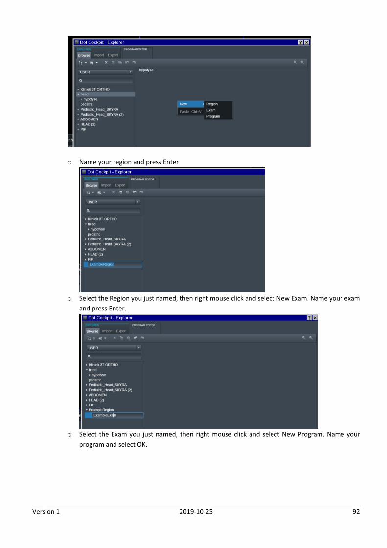
Version 1 2019-10-25 92
o Name your region and press Enter
o Select the Region you just named, then right mouse click and select New Exam. Name your exam
and press Enter.
o Select the Exam you just named, then right mouse click and select New Program. Name your
program and select OK.
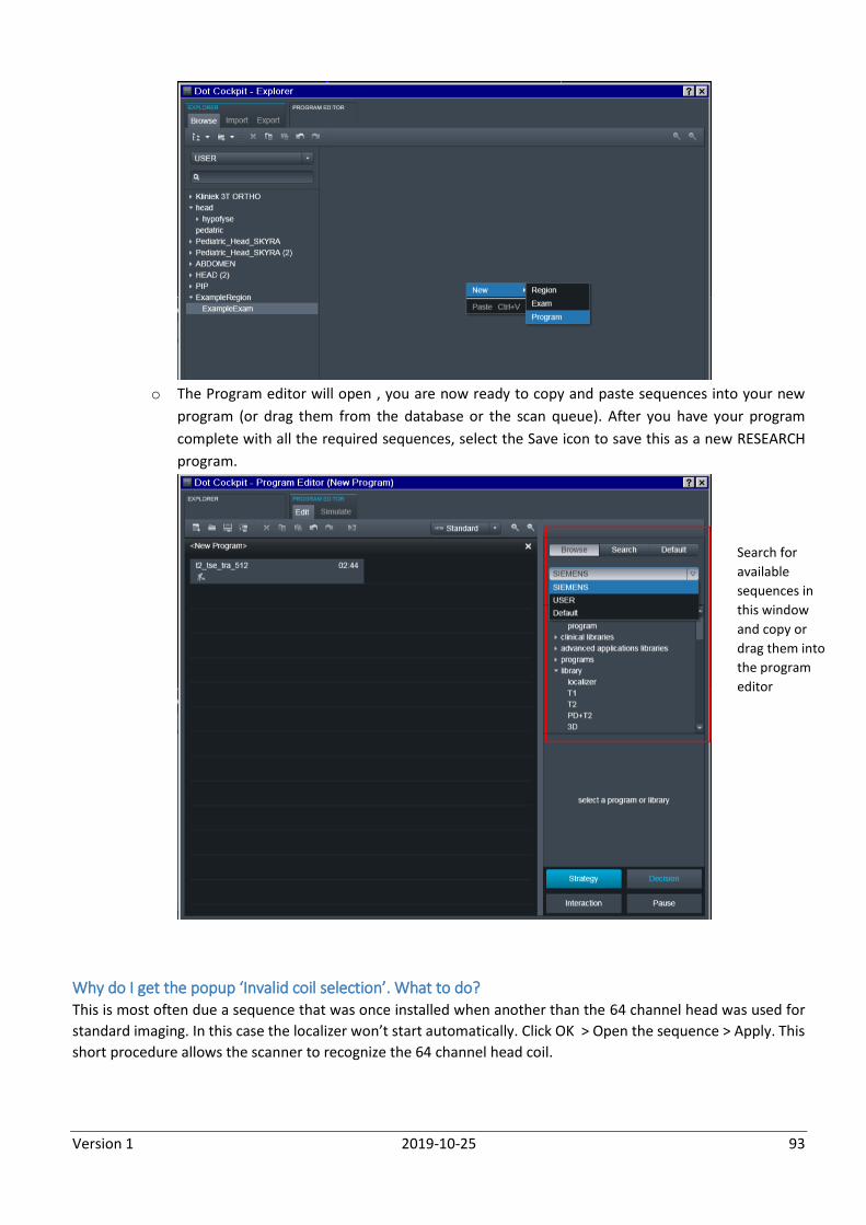
Version 1 2019-10-25 93
o The Program editor will open , you are now ready to copy and paste sequences into your new
program (or drag them from the database or the scan queue). After you have your program
complete with all the required sequences, select the Save icon to save this as a new RESEARCH
program.
Why do I get the popup ‘Invalid coil selection’. What to do? This is most often due a sequence that was once installed when another than the 64 channel head was used for
standard imaging. In this case the localizer won’t start automatically. Click OK > Open the sequence > Apply. This
short procedure allows the scanner to recognize the 64 channel head coil.
Search for
available
sequences in
this window
and copy or
drag them into
the program
editor
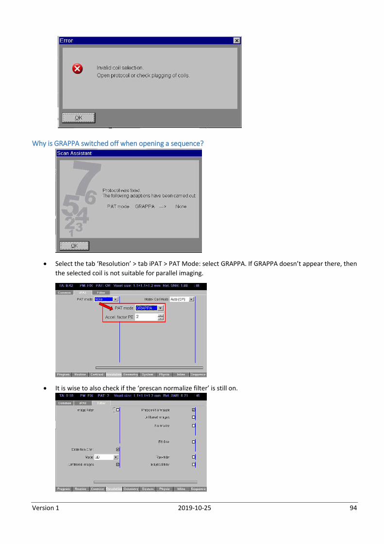
Version 1 2019-10-25 94
Why is GRAPPA switched off when opening a sequence?
Select the tab ‘Resolution’ > tab iPAT > PAT Mode: select GRAPPA. If GRAPPA doesn’t appear there, then
the selected coil is not suitable for parallel imaging.
It is wise to also check if the ‘prescan normalize filter’ is still on.
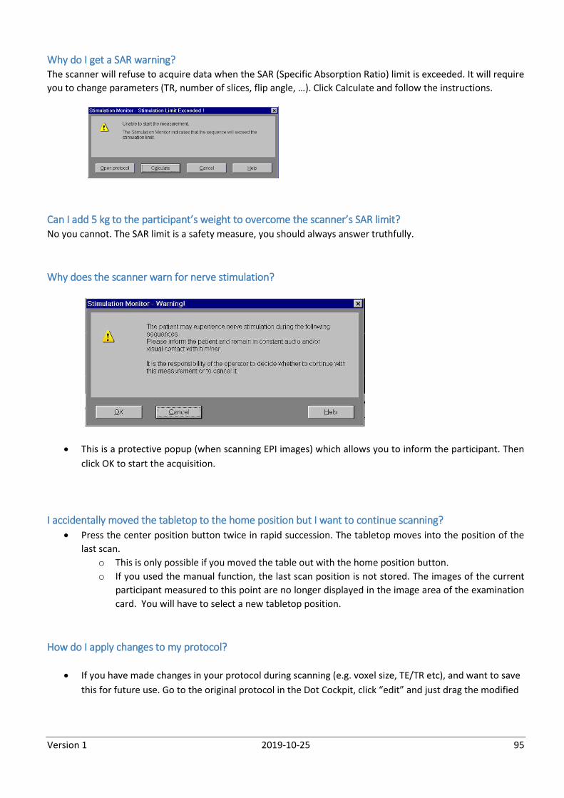
Version 1 2019-10-25 95
Why do I get a SAR warning? The scanner will refuse to acquire data when the SAR (Specific Absorption Ratio) limit is exceeded. It will require
you to change parameters (TR, number of slices, flip angle, …). Click Calculate and follow the instructions.
Can I add 5 kg to the participant’s weight to overcome the scanner’s SAR limit? No you cannot. The SAR limit is a safety measure, you should always answer truthfully.
Why does the scanner warn for nerve stimulation?
This is a protective popup (when scanning EPI images) which allows you to inform the participant. Then
click OK to start the acquisition.
I accidentally moved the tabletop to the home position but I want to continue scanning?
Press the center position button twice in rapid succession. The tabletop moves into the position of the
last scan.
o This is only possible if you moved the table out with the home position button.
o If you used the manual function, the last scan position is not stored. The images of the current
participant measured to this point are no longer displayed in the image area of the examination
card. You will have to select a new tabletop position.
How do I apply changes to my protocol?
If you have made changes in your protocol during scanning (e.g. voxel size, TE/TR etc), and want to save
this for future use. Go to the original protocol in the Dot Cockpit, click “edit” and just drag the modified
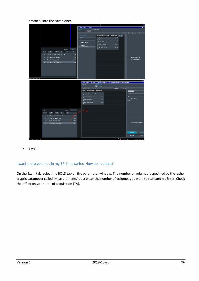
Version 1 2019-10-25 96
protocol into the saved one:
Save.
I want more volumes in my EPI time series. How do I do that?
On the Exam tab, select the BOLD tab on the parameter window. The number of volumes is specified by the rather
cryptic parameter called ‘Measurements’. Just enter the number of volumes you want to scan and hit Enter. Check
the effect on your time of acquisition (TA).
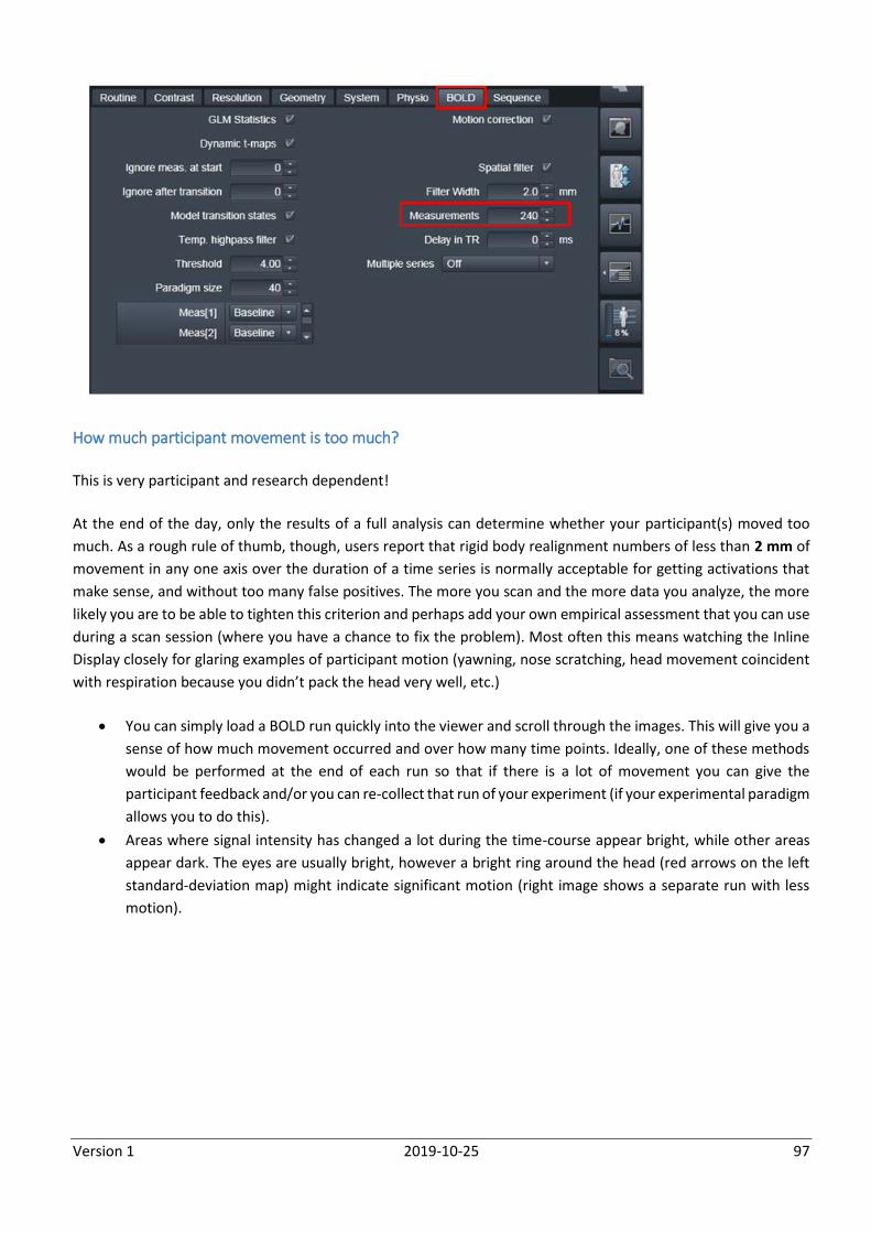
Version 1 2019-10-25 97
How much participant movement is too much?
This is very participant and research dependent!
At the end of the day, only the results of a full analysis can determine whether your participant(s) moved too
much. As a rough rule of thumb, though, users report that rigid body realignment numbers of less than 2 mm of
movement in any one axis over the duration of a time series is normally acceptable for getting activations that
make sense, and without too many false positives. The more you scan and the more data you analyze, the more
likely you are to be able to tighten this criterion and perhaps add your own empirical assessment that you can use
during a scan session (where you have a chance to fix the problem). Most often this means watching the Inline
Display closely for glaring examples of participant motion (yawning, nose scratching, head movement coincident
with respiration because you didn’t pack the head very well, etc.)
You can simply load a BOLD run quickly into the viewer and scroll through the images. This will give you a
sense of how much movement occurred and over how many time points. Ideally, one of these methods
would be performed at the end of each run so that if there is a lot of movement you can give the
participant feedback and/or you can re-collect that run of your experiment (if your experimental paradigm
allows you to do this).
Areas where signal intensity has changed a lot during the time-course appear bright, while other areas
appear dark. The eyes are usually bright, however a bright ring around the head (red arrows on the left
standard-deviation map) might indicate significant motion (right image shows a separate run with less
motion).
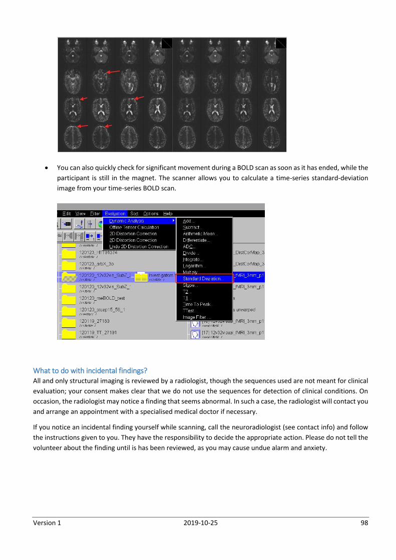
Version 1 2019-10-25 98
You can also quickly check for significant movement during a BOLD scan as soon as it has ended, while the
participant is still in the magnet. The scanner allows you to calculate a time-series standard-deviation
image from your time-series BOLD scan.
What to do with incidental findings? All and only structural imaging is reviewed by a radiologist, though the sequences used are not meant for clinical
evaluation; your consent makes clear that we do not use the sequences for detection of clinical conditions. On
occasion, the radiologist may notice a finding that seems abnormal. In such a case, the radiologist will contact you
and arrange an appointment with a specialised medical doctor if necessary.
If you notice an incidental finding yourself while scanning, call the neuroradiologist (see contact info) and follow
the instructions given to you. They have the responsibility to decide the appropriate action. Please do not tell the
volunteer about the finding until is has been reviewed, as you may cause undue alarm and anxiety.
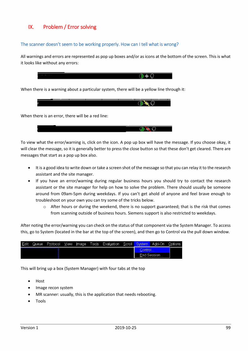
Version 1 2019-10-25 99
IX. Problem / Error solving
The scanner doesn’t seem to be working properly. How can I tell what is wrong?
All warnings and errors are represented as pop up boxes and/or as icons at the bottom of the screen. This is what
it looks like without any errors:
When there is a warning about a particular system, there will be a yellow line through it:
When there is an error, there will be a red line:
To view what the error/warning is, click on the icon. A pop up box will have the message. If you choose okay, it
will clear the message, so it is generally better to press the close button so that these don’t get cleared. There are
messages that start as a pop up box also.
It is a good idea to write down or take a screen shot of the message so that you can relay it to the research
assistant and the site manager.
If you have an error/warning during regular business hours you should try to contact the research
assistant or the site manager for help on how to solve the problem. There should usually be someone
around from 09am-5pm during weekdays. If you can’t get ahold of anyone and feel brave enough to
troubleshoot on your own you can try some of the tricks below.
o After hours or during the weekend, there is no support guaranteed; that is the risk that comes
from scanning outside of business hours. Siemens support is also restricted to weekdays.
After noting the error/warning you can check on the status of that component via the System Manager. To access
this, go to System (located in the bar at the top of the screen), and then go to Control via the pull down window.
This will bring up a box (System Manager) with four tabs at the top
Host
Image recon system
MR scanner: usually, this is the application that needs rebooting.
Tools
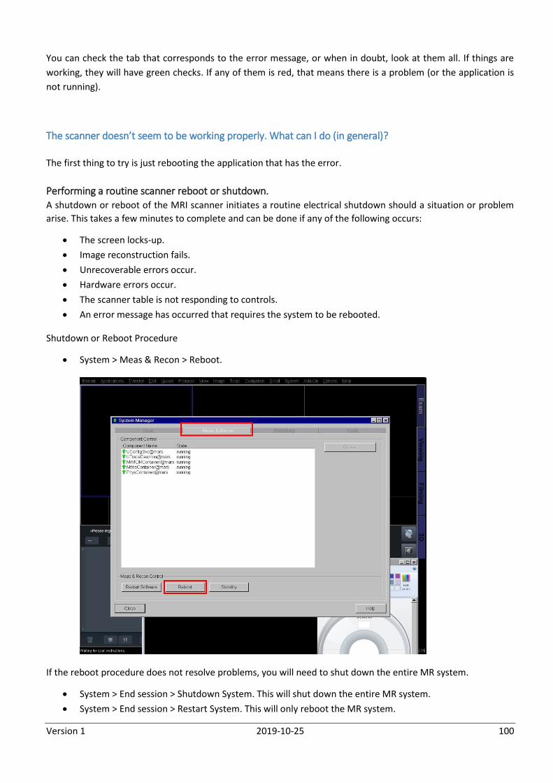
Version 1 2019-10-25 100
You can check the tab that corresponds to the error message, or when in doubt, look at them all. If things are
working, they will have green checks. If any of them is red, that means there is a problem (or the application is
not running).
The scanner doesn’t seem to be working properly. What can I do (in general)?
The first thing to try is just rebooting the application that has the error.
Performing a routine scanner reboot or shutdown. A shutdown or reboot of the MRI scanner initiates a routine electrical shutdown should a situation or problem
arise. This takes a few minutes to complete and can be done if any of the following occurs:
The screen locks-up.
Image reconstruction fails.
Unrecoverable errors occur.
Hardware errors occur.
The scanner table is not responding to controls.
An error message has occurred that requires the system to be rebooted.
Shutdown or Reboot Procedure
System > Meas & Recon > Reboot.
If the reboot procedure does not resolve problems, you will need to shut down the entire MR system.
System > End session > Shutdown System. This will shut down the entire MR system.
System > End session > Restart System. This will only reboot the MR system.
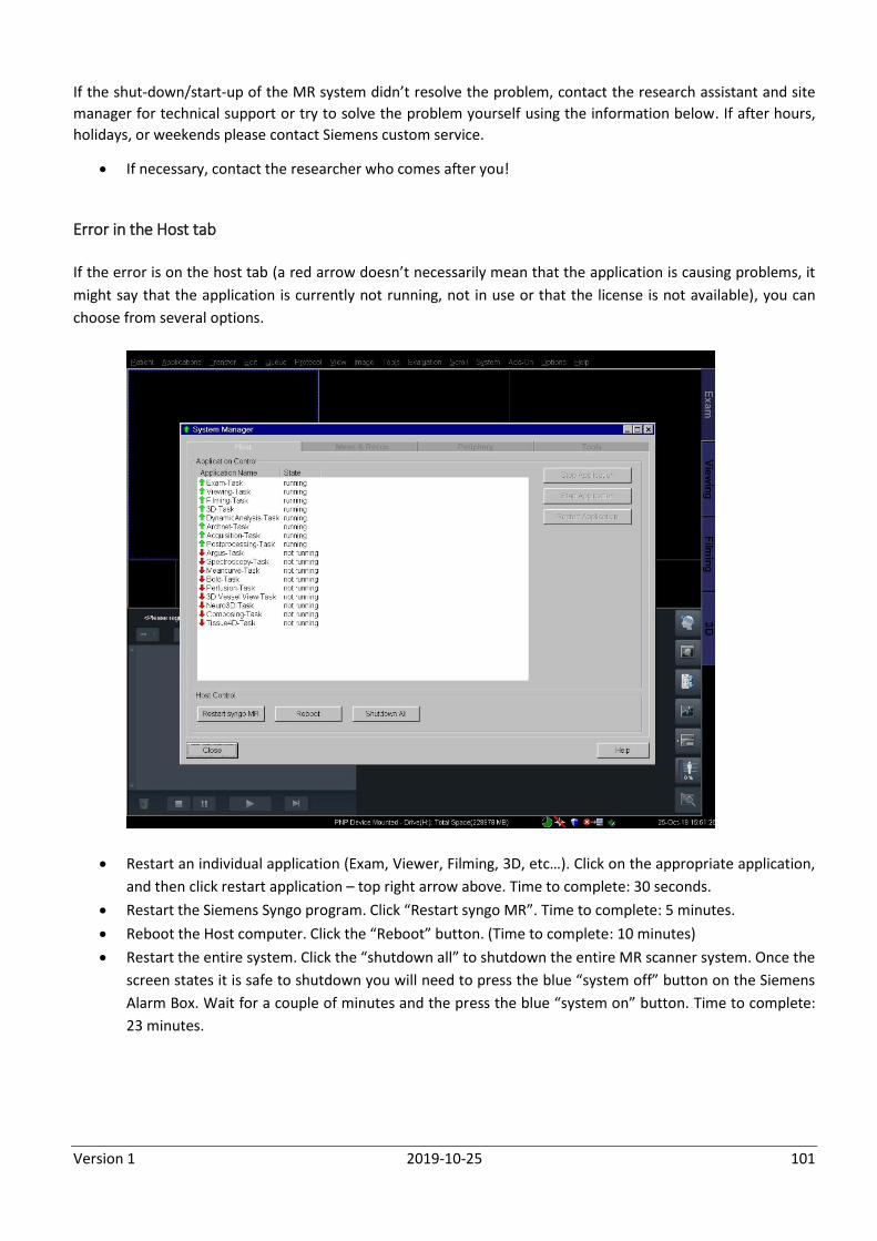
Version 1 2019-10-25 101
If the shut-down/start-up of the MR system didn’t resolve the problem, contact the research assistant and site
manager for technical support or try to solve the problem yourself using the information below. If after hours,
holidays, or weekends please contact Siemens custom service.
If necessary, contact the researcher who comes after you!
Error in the Host tab
If the error is on the host tab (a red arrow doesn’t necessarily mean that the application is causing problems, it
might say that the application is currently not running, not in use or that the license is not available), you can
choose from several options.
Restart an individual application (Exam, Viewer, Filming, 3D, etc…). Click on the appropriate application,
and then click restart application – top right arrow above. Time to complete: 30 seconds.
Restart the Siemens Syngo program. Click “Restart syngo MR”. Time to complete: 5 minutes.
Reboot the Host computer. Click the “Reboot” button. (Time to complete: 10 minutes)
Restart the entire system. Click the “shutdown all” to shutdown the entire MR scanner system. Once the
screen states it is safe to shutdown you will need to press the blue “system off” button on the Siemens
Alarm Box. Wait for a couple of minutes and the press the blue “system on” button. Time to complete:
23 minutes.
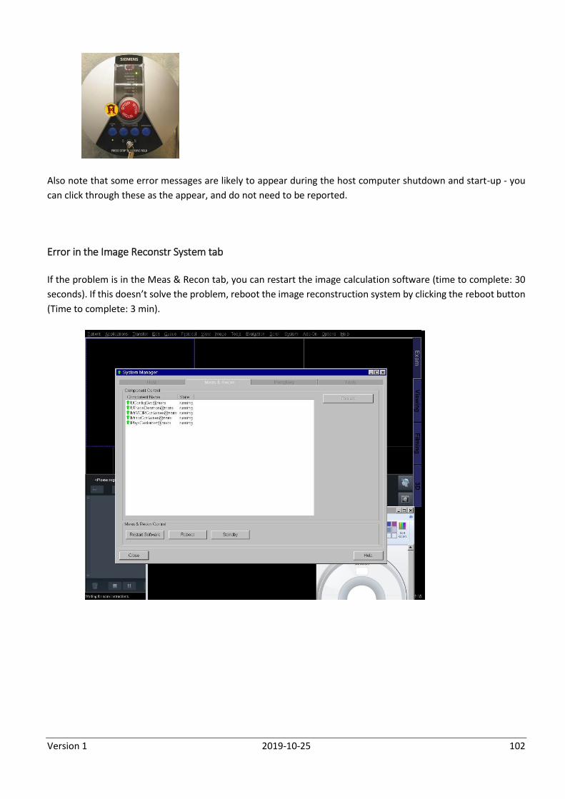
Version 1 2019-10-25 102
Also note that some error messages are likely to appear during the host computer shutdown and start-up - you
can click through these as the appear, and do not need to be reported.
Error in the Image Reconstr System tab
If the problem is in the Meas & Recon tab, you can restart the image calculation software (time to complete: 30
seconds). If this doesn’t solve the problem, reboot the image reconstruction system by clicking the reboot button
(Time to complete: 3 min).
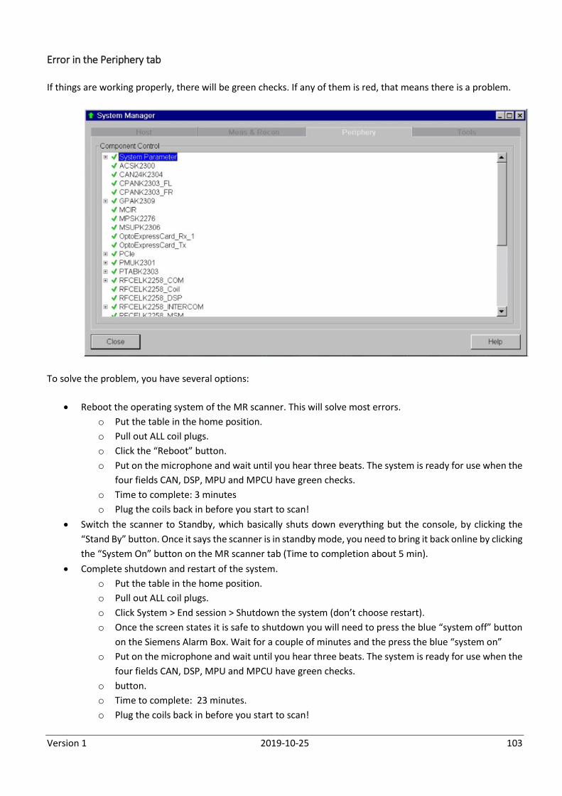
Version 1 2019-10-25 103
Error in the Periphery tab
If things are working properly, there will be green checks. If any of them is red, that means there is a problem.
To solve the problem, you have several options:
Reboot the operating system of the MR scanner. This will solve most errors.
o Put the table in the home position.
o Pull out ALL coil plugs.
o Click the “Reboot” button.
o Put on the microphone and wait until you hear three beats. The system is ready for use when the
four fields CAN, DSP, MPU and MPCU have green checks.
o Time to complete: 3 minutes
o Plug the coils back in before you start to scan!
Switch the scanner to Standby, which basically shuts down everything but the console, by clicking the
“Stand By” button. Once it says the scanner is in standby mode, you need to bring it back online by clicking
the “System On” button on the MR scanner tab (Time to completion about 5 min).
Complete shutdown and restart of the system.
o Put the table in the home position.
o Pull out ALL coil plugs.
o Click System > End session > Shutdown the system (don’t choose restart).
o Once the screen states it is safe to shutdown you will need to press the blue “system off” button
on the Siemens Alarm Box. Wait for a couple of minutes and the press the blue “system on”
o Put on the microphone and wait until you hear three beats. The system is ready for use when the
four fields CAN, DSP, MPU and MPCU have green checks.
o button.
o Time to complete: 23 minutes.
o Plug the coils back in before you start to scan!
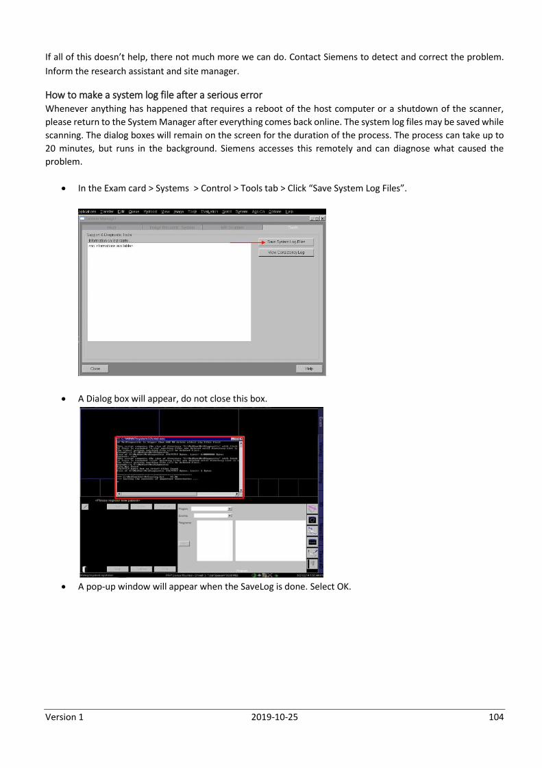
Version 1 2019-10-25 104
If all of this doesn’t help, there not much more we can do. Contact Siemens to detect and correct the problem.
Inform the research assistant and site manager.
How to make a system log file after a serious error Whenever anything has happened that requires a reboot of the host computer or a shutdown of the scanner,
please return to the System Manager after everything comes back online. The system log files may be saved while
scanning. The dialog boxes will remain on the screen for the duration of the process. The process can take up to
20 minutes, but runs in the background. Siemens accesses this remotely and can diagnose what caused the
problem.
In the Exam card > Systems > Control > Tools tab > Click “Save System Log Files”.
A Dialog box will appear, do not close this box.
A pop-up window will appear when the SaveLog is done. Select OK.
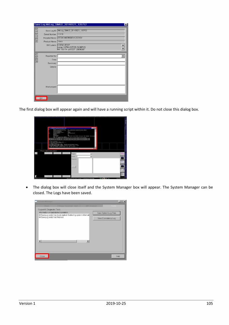
Version 1 2019-10-25 105
The first dialog box will appear again and will have a running script within it. Do not close this dialog box.
The dialog box will close itself and the System Manager box will appear. The System Manager can be
closed. The Logs have been saved.
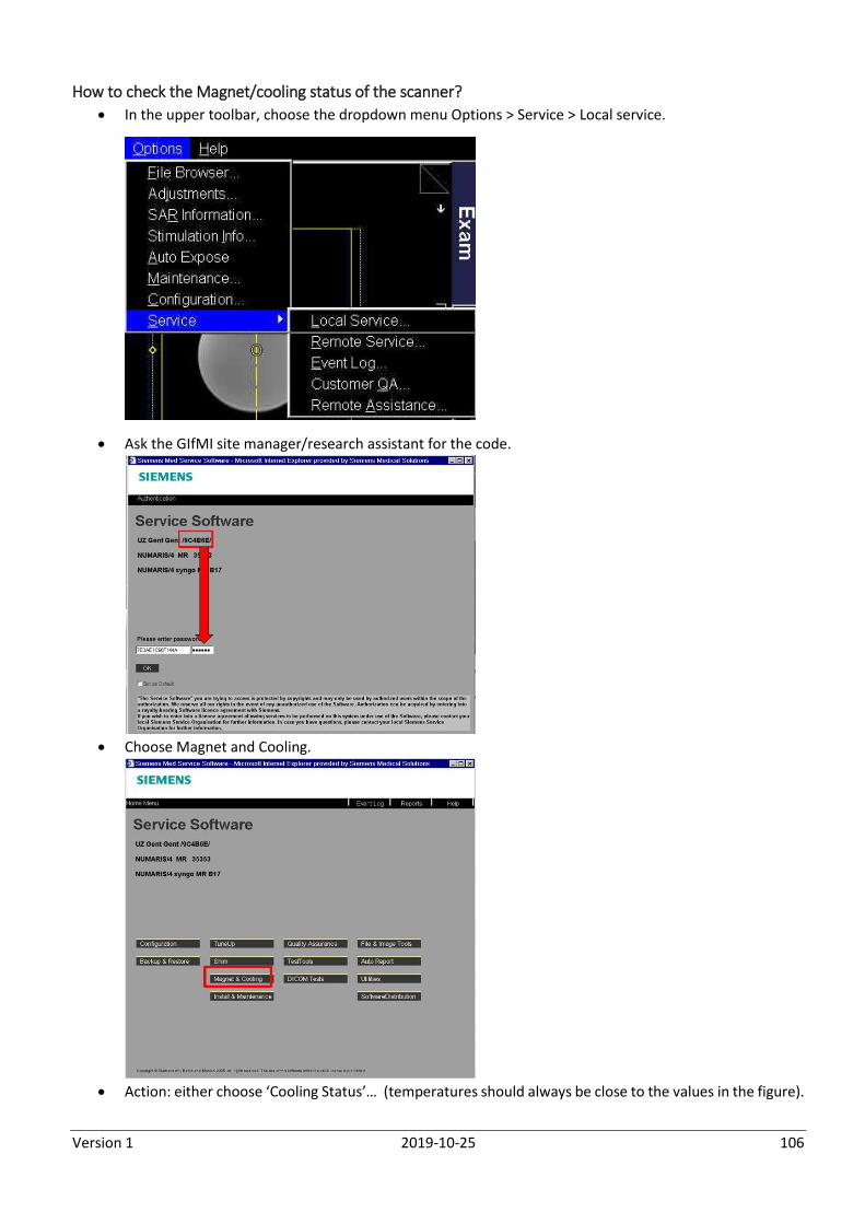
Version 1 2019-10-25 106
How to check the Magnet/cooling status of the scanner?
In the upper toolbar, choose the dropdown menu Options > Service > Local service.
Ask the GIfMI site manager/research assistant for the code.
Choose Magnet and Cooling.
Action: either choose ‘Cooling Status’… (temperatures should always be close to the values in the figure).
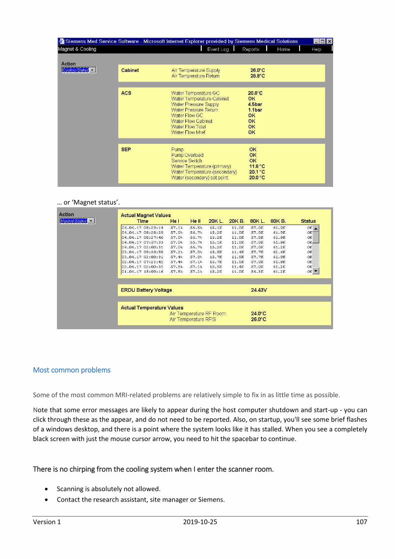
Version 1 2019-10-25 107
… or ‘Magnet status’.
Most common problems
Some of the most common MRI-related problems are relatively simple to fix in as little time as possible.
Note that some error messages are likely to appear during the host computer shutdown and start-up - you can
click through these as the appear, and do not need to be reported. Also, on startup, you'll see some brief flashes
of a windows desktop, and there is a point where the system looks like it has stalled. When you see a completely
black screen with just the mouse cursor arrow, you need to hit the spacebar to continue.
There is no chirping from the cooling system when I enter the scanner room.
Scanning is absolutely not allowed.
Contact the research assistant, site manager or Siemens.
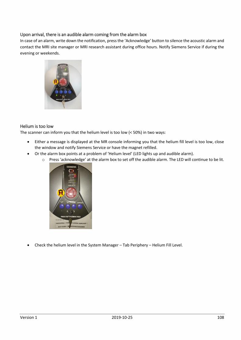
Version 1 2019-10-25 108
Upon arrival, there is an audible alarm coming from the alarm box In case of an alarm, write down the notification, press the ‘Acknowledge’ button to silence the acoustic alarm and
contact the MRI site manager or MRI research assistant during office hours. Notify Siemens Service if during the
evening or weekends.
Helium is too low The scanner can inform you that the helium level is too low (< 50%) in two ways:
Either a message is displayed at the MR console informing you that the helium fill level is too low, close
the window and notify Siemens Service or have the magnet refilled.
Or the alarm box points at a problem of ‘Helium level’ (LED lights up and audible alarm).
o Press ‘acknowledge’ at the alarm box to set off the audible alarm. The LED will continue to be lit.
Check the helium level in the System Manager – Tab Periphery – Helium Fill Level.
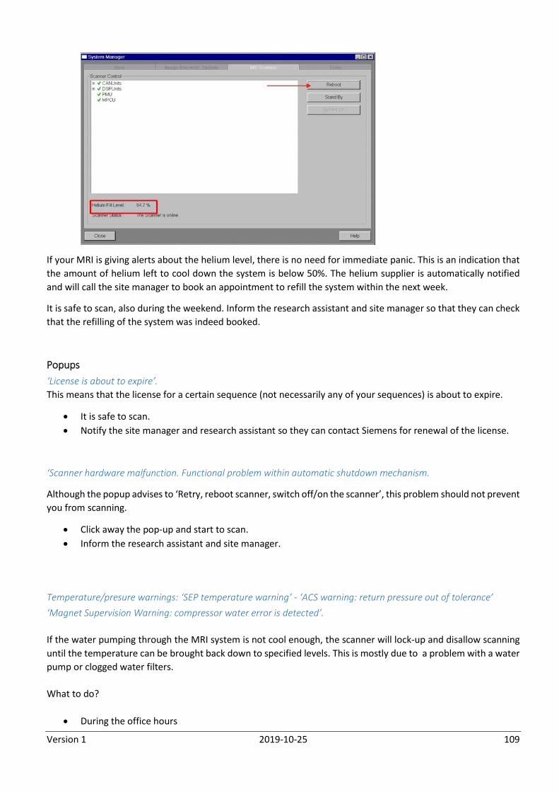
Version 1 2019-10-25 109
If your MRI is giving alerts about the helium level, there is no need for immediate panic. This is an indication that
the amount of helium left to cool down the system is below 50%. The helium supplier is automatically notified
and will call the site manager to book an appointment to refill the system within the next week.
It is safe to scan, also during the weekend. Inform the research assistant and site manager so that they can check
that the refilling of the system was indeed booked.
Popups
‘License is about to expire’.
This means that the license for a certain sequence (not necessarily any of your sequences) is about to expire.
It is safe to scan.
Notify the site manager and research assistant so they can contact Siemens for renewal of the license.
‘Scanner hardware malfunction. Functional problem within automatic shutdown mechanism.
Although the popup advises to ‘Retry, reboot scanner, switch off/on the scanner’, this problem should not prevent
you from scanning.
Click away the pop-up and start to scan.
Inform the research assistant and site manager.
Temperature/presure warnings: ‘SEP temperature warning’ - ‘ACS warning: return pressure out of tolerance’
‘Magnet Supervision Warning: compressor water error is detected’.
If the water pumping through the MRI system is not cool enough, the scanner will lock-up and disallow scanning
until the temperature can be brought back down to specified levels. This is mostly due to a problem with a water
pump or clogged water filters.
What to do?
During the office hours
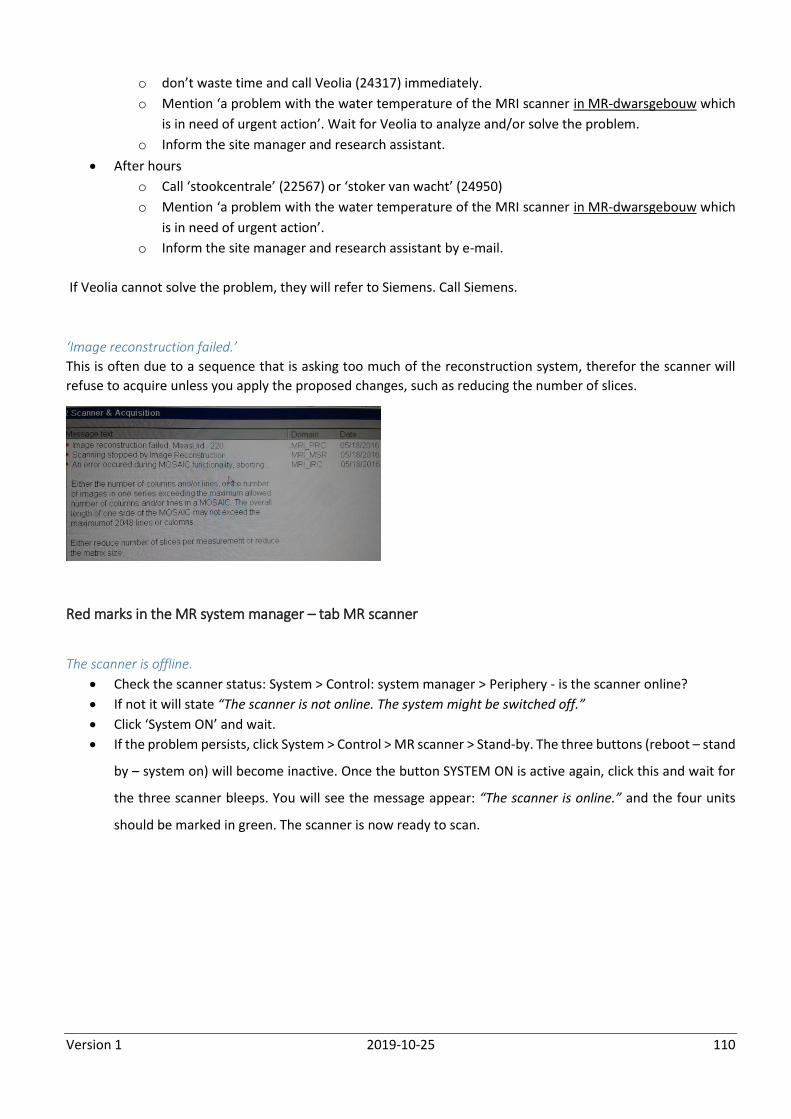
Version 1 2019-10-25 110
o don’t waste time and call Veolia (24317) immediately.
o Mention ‘a problem with the water temperature of the MRI scanner in MR-dwarsgebouw which
is in need of urgent action’. Wait for Veolia to analyze and/or solve the problem.
o Inform the site manager and research assistant.
After hours
o Call ‘stookcentrale’ (22567) or ‘stoker van wacht’ (24950)
o Mention ‘a problem with the water temperature of the MRI scanner in MR-dwarsgebouw which
is in need of urgent action’.
o Inform the site manager and research assistant by e-mail.
If Veolia cannot solve the problem, they will refer to Siemens. Call Siemens.
‘Image reconstruction failed.’
This is often due to a sequence that is asking too much of the reconstruction system, therefor the scanner will
refuse to acquire unless you apply the proposed changes, such as reducing the number of slices.
Red marks in the MR system manager – tab MR scanner
The scanner is offline.
Check the scanner status: System > Control: system manager > Periphery - is the scanner online?
If not it will state “The scanner is not online. The system might be switched off.”
Click ‘System ON’ and wait.
If the problem persists, click System > Control > MR scanner > Stand-by. The three buttons (reboot – stand
by – system on) will become inactive. Once the button SYSTEM ON is active again, click this and wait for
the three scanner bleeps. You will see the message appear: “The scanner is online.” and the four units
should be marked in green. The scanner is now ready to scan.
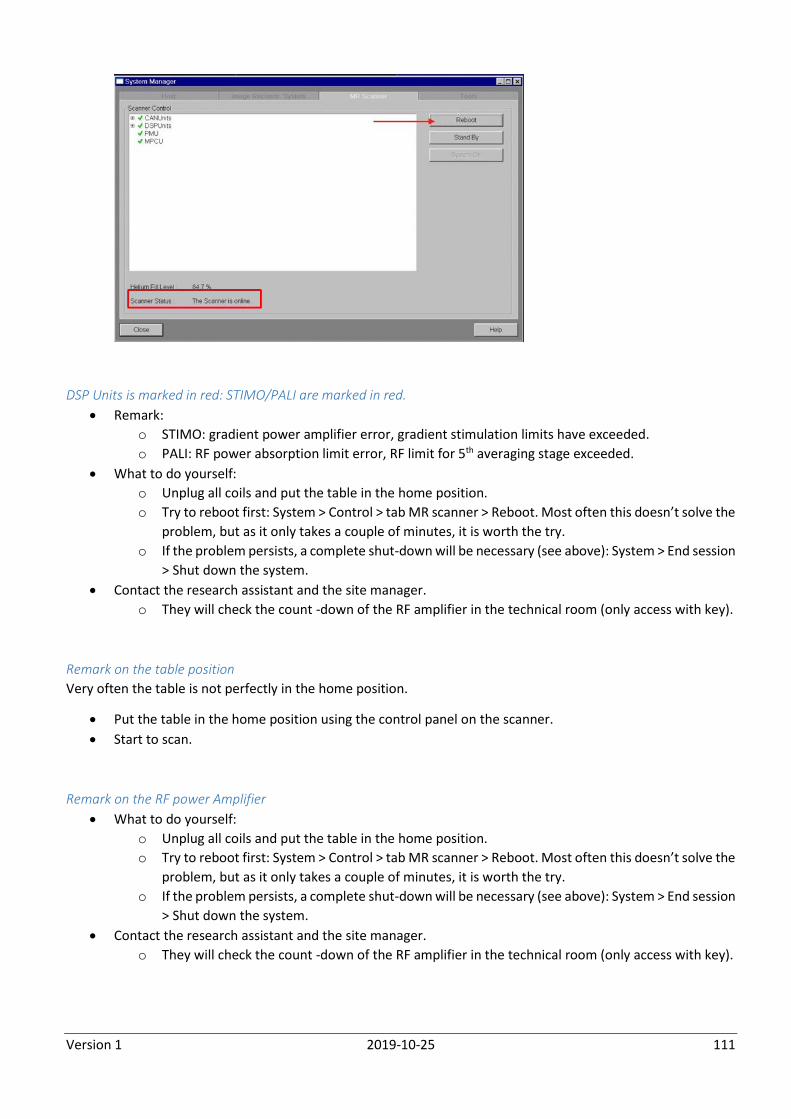
Version 1 2019-10-25 111
DSP Units is marked in red: STIMO/PALI are marked in red.
Remark:
o STIMO: gradient power amplifier error, gradient stimulation limits have exceeded.
o PALI: RF power absorption limit error, RF limit for 5th averaging stage exceeded.
What to do yourself:
o Unplug all coils and put the table in the home position.
o Try to reboot first: System > Control > tab MR scanner > Reboot. Most often this doesn’t solve the
problem, but as it only takes a couple of minutes, it is worth the try.
o If the problem persists, a complete shut-down will be necessary (see above): System > End session
> Shut down the system.
Contact the research assistant and the site manager.
o They will check the count -down of the RF amplifier in the technical room (only access with key).
Remark on the table position
Very often the table is not perfectly in the home position.
Put the table in the home position using the control panel on the scanner.
Start to scan.
Remark on the RF power Amplifier
What to do yourself:
o Unplug all coils and put the table in the home position.
o Try to reboot first: System > Control > tab MR scanner > Reboot. Most often this doesn’t solve the
problem, but as it only takes a couple of minutes, it is worth the try.
o If the problem persists, a complete shut-down will be necessary (see above): System > End session
> Shut down the system.
Contact the research assistant and the site manager.
o They will check the count -down of the RF amplifier in the technical room (only access with key).
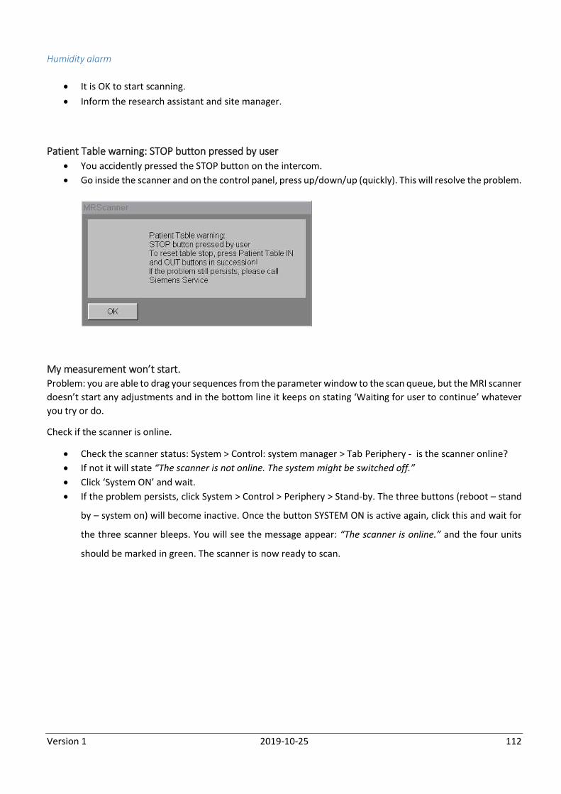
Version 1 2019-10-25 112
Humidity alarm
It is OK to start scanning.
Inform the research assistant and site manager.
Patient Table warning: STOP button pressed by user
You accidently pressed the STOP button on the intercom.
Go inside the scanner and on the control panel, press up/down/up (quickly). This will resolve the problem.
My measurement won’t start. Problem: you are able to drag your sequences from the parameter window to the scan queue, but the MRI scanner
doesn’t start any adjustments and in the bottom line it keeps on stating ‘Waiting for user to continue’ whatever
you try or do.
Check if the scanner is online.
Check the scanner status: System > Control: system manager > Tab Periphery - is the scanner online?
If not it will state “The scanner is not online. The system might be switched off.”
Click ‘System ON’ and wait.
If the problem persists, click System > Control > Periphery > Stand-by. The three buttons (reboot – stand
by – system on) will become inactive. Once the button SYSTEM ON is active again, click this and wait for
the three scanner bleeps. You will see the message appear: “The scanner is online.” and the four units
should be marked in green. The scanner is now ready to scan.
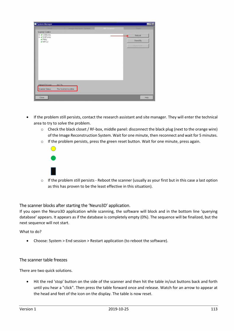
Version 1 2019-10-25 113
If the problem still persists, contact the research assistant and site manager. They will enter the technical
area to try to solve the problem.
o Check the black closet / RF-box, middle panel: disconnect the black plug (next to the orange wire)
of the Image Reconstruction System. Wait for one minute, then reconnect and wait for 5 minutes.
o If the problem persists, press the green reset button. Wait for one minute, press again.
o If the problem still persists - Reboot the scanner (usually as your first but in this case a last option
as this has proven to be the least effective in this situation).
The scanner blocks after starting the ‘Neuro3D’ application. If you open the Neuro3D application while scanning, the software will block and in the bottom line ‘querying
database’ appears. It appears as if the database is completely empty (0%). The sequence will be finalized, but the
next sequence will not start.
What to do?
Choose: System > End session > Restart application (to reboot the software).
The scanner table freezes
There are two quick solutions.
Hit the red 'stop' button on the side of the scanner and then hit the table in/out buttons back and forth
until you hear a "click". Then press the table forward once and release. Watch for an arrow to appear at
the head and feet of the icon on the display. The table is now reset.
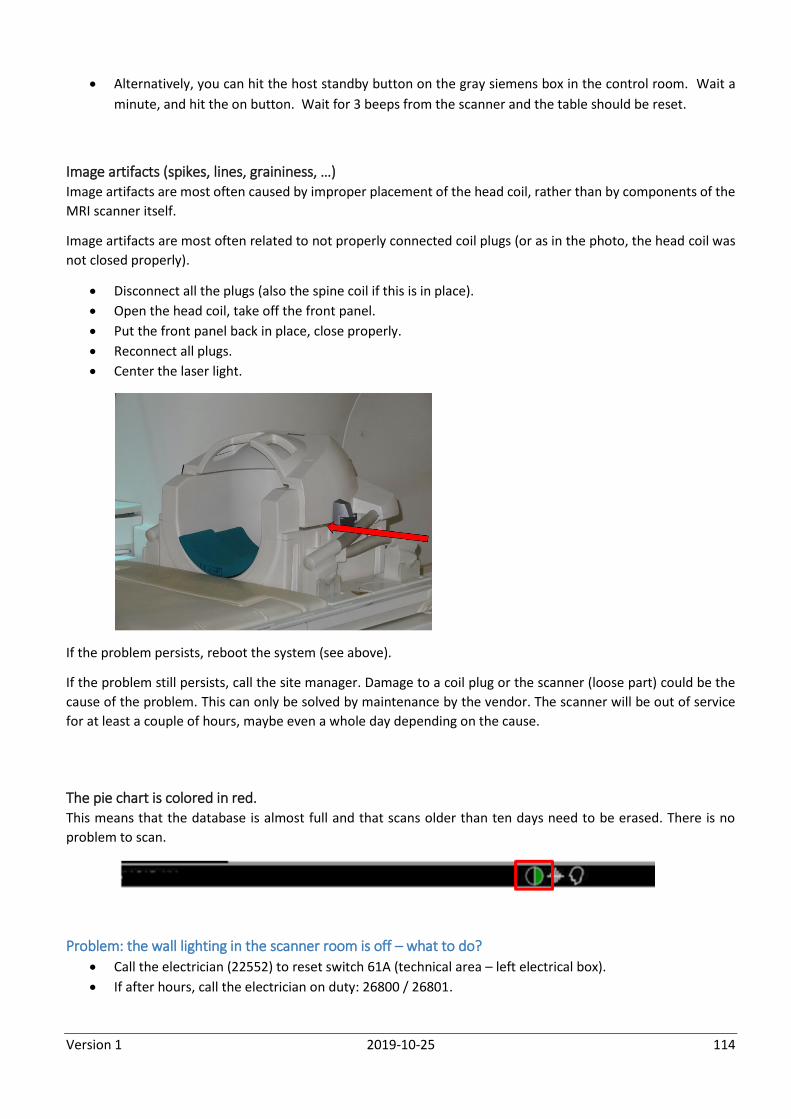
Version 1 2019-10-25 114
Alternatively, you can hit the host standby button on the gray siemens box in the control room. Wait a
minute, and hit the on button. Wait for 3 beeps from the scanner and the table should be reset.
Image artifacts (spikes, lines, graininess, …) Image artifacts are most often caused by improper placement of the head coil, rather than by components of the
MRI scanner itself.
Image artifacts are most often related to not properly connected coil plugs (or as in the photo, the head coil was
not closed properly).
Disconnect all the plugs (also the spine coil if this is in place).
Open the head coil, take off the front panel.
Put the front panel back in place, close properly.
Reconnect all plugs.
Center the laser light.
If the problem persists, reboot the system (see above).
If the problem still persists, call the site manager. Damage to a coil plug or the scanner (loose part) could be the
cause of the problem. This can only be solved by maintenance by the vendor. The scanner will be out of service
for at least a couple of hours, maybe even a whole day depending on the cause.
The pie chart is colored in red. This means that the database is almost full and that scans older than ten days need to be erased. There is no
problem to scan.
Problem: the wall lighting in the scanner room is off – what to do?
Call the electrician (22552) to reset switch 61A (technical area – left electrical box).
If after hours, call the electrician on duty: 26800 / 26801.

Version 1 2019-10-25 115
X. Contact
Reporting incidents All accidents and/or incidents (this also refers to near incidents) must be reported. An accident/incident report
form is available from www.cabiatl.com, and this should be submitted to the site manager/research assistant
within 24-hours of the event.
Who to contact?
Local supportive staff:
o Research Assistant: [email protected] (25062)
o Site Manager: [email protected] (24820)
o MRI physicist: [email protected] (28975)
Siemens central: 02/536.46.20 (They will ask for the number of the Siemens Prisma UZ Gent: 017-000166-
73)
Neuroradiologists
o Prof. Dr. Eric Achten: [email protected] (24071)
o Prof. Dr. Karel Deblaere: [email protected] (26674)