Embed Size (px)
Citation preview
U s e r M a n u a l
pp
g i g a B E R T 1 4 0 0
1 4 0 0 M b / s B i t E r r o r R a t e T e s t e rG e n e r a t o r a n d A n a l y z e r
071-0590-00
This document supports firmware version 2.2 and above.
Advanced Test Equipment Rentalswww.atecorp.com 800-404-ATEC (2832)
®
Established 1981
GB1400 User Manualii
Copyright © 2000 Tektronix, Inc. All rights reserved. Licensed softwareproducts are owned by Tektronix or its suppliers and are protected by UnitedStates copyright laws and international treaty provisions.
Use, duplication, or disclosure by the Government is subject to restrictions as setforth in subparagraph (c)(1)(ii) of the Rights in Technical Data and ComputerSoftware clause at DFARS 252.227-7013, or subparagraphs (c)(1) and (2) of theCommercial Computer Software - Restricted Rights clause at FAR 52.227-19, asapplicable.
Tektronix products are covered by U.S. and foreign patents, issued and pending.Information in this publication supersedes that in all previously publishedmaterial. Specifications and price change privileges reserved.
Tektronix, Inc., P.O. Box 1000, Wilsonville, OR 97070-1000
TEKTRONIX and TEK are registered trademarks of Tektronix, Inc.

GB1400 User Manual iii
WARRANTY
Tektronix warrants that this product will be free from defects in materials and workmanship for aperiod of one (1) year from the date of shipment. If any such product proves defective during thiswarranty period, Tektronix, at its option, either will repair the defective product without chargefor parts and labor, or will provide a replacement in exchange for the defective product.
In order to obtain service under this warranty, Customer must notify Tektronix of the defectbefore the expiration of the warranty period and make suitable arrangements for the performanceof service. Customer shall be responsible for packaging and shipping the defective product to theservice center designated by Tektronix, with shipping charges prepaid. Tektronix shall pay forthe return of the product to Customer if the shipment is to a location within the country in whichTektronix service center is located. Customer shall be responsible for paying all shipping charges,duties, taxes, and any other charges for products returned to any other locations.
This warranty shall not apply to any defect, failure or damage caused by improper use orimproper or inadequate maintenance and care. Tektronix shall not be obligated to furnish serviceunder warranty a) to repair damage resulting from attempts by personnel other than Tektronixrepresentatives to install, repair or service the product; b) to repair damage resulting fromimproper user or connection to incompatible equipment; or c) to service a product that has beenmodified or integrated with other products when the effect of such modification or integrationincreases the time or difficulty of servicing the product.
THIS WARRANTY IS GIVEN BY TEKTRONIX WITH RESPECT TO THIS PRODUCTIN LIEU OF ANY OTHER WARRANTIES, EXPRESSED OR IMPLIED. TEKTRONIXAND ITS VENDORS DISCLAIM ANY IMPLIED WARRANTIES OFMERCHANTABILITY OR FITNESS FOR A PARTICULAR PURPOSE. TEKTRONIX’RESPONSIBILITY TO REPAIR OR REPLACE DEFECTIVE PRODUCTS IS THESOLE AND EXCLUSIVE REMEDY PROVIDED TO THE CUSTOMER FOR BREACHOF THIS WARRANTY. TEKTRONIX AND ITS VENDORS WILL NOT BE LIABLEFOR ANY INDIRECT, SPECIAL, INCIDENTAL, OR CONSEQUENTIAL DAMAGESIRRESPECTIVE OF WHETHER TEKTRONIX OR THE VENDOR HAS ADVANCENOTICE OF THE POSSIBILITY OF SUCH DAMAGES.

GB1400 User Manualiv
How to Reach Customer Service
If you have any questions regarding the operation, maintenance, repair,or application of your Tektronix equipment, contact your local salesand service office. For a complete list of the Worldwide Sales andService Offices contact (800) 426-2200.
Tektronix provides high quality Technical Support on applications,operation, measurement specifications, hardware, and software byexpert application engineers. For Applications Support, call theCustomer Support Center listed below.
MailingAddress
Tektronix, Inc.Measurement Business DivisionP.O. Box 500Beaverton, Oregon 97077-0001USA
Attn. Customer Service
Customerand SalesSupportCenter
800-TEK-WIDE or800-835-9433 Ext 2400
Hours are 6:00 AM to 5:00 PM,Pacific Time.
After hours Voice Mail is available.
Direct 503-627-2400
Fax 503-627-5695
E-Mail [email protected]
Web Site http://www.tek.com

GB1400 User Manual v
Table of ContentsSafety .................................................................................................. xii
Getting Started
Features............................................................................................... 1-1
Ordering Information............................................................................ 1-4
gigaBERT comparison chart.................................................................. 1-5
Initial Self-Check Procedure ................................................................. 1-7
Operating Basics
Functional Overview....................................................................................... 2-1
BERT Basics - GB1400 ........................................................................ 2-2
Controls, Indicators, and Connectors...................................................... 2-4
Display Formats ................................................................................... 2-6
Outputs & Inputs .................................................................................. 2-9
Generator OUTPUT ....................................................................... 2-9
Generator CLOCK ......................................................................... 2-10
Generator OUTPUT (Set-up)........................................................... 2-11
Generator Rear Panel...................................................................... 2-12
Changing the Line Fuse .................................................................. 2-12
Analyzer INPUT ............................................................................ 2-13
Analyzer MONITOR...................................................................... 2-14
Analyzer Rear Panel....................................................................... 2-15
Changing the Line Fuse .................................................................. 2-15
Connectors, Terminations and Levels .............................................. 2-16
Controls & Indicators............................................................................ 2-18
Power Switches.............................................................................. 2-18
Unit Mounting ............................................................................... 2-18
Unit Cooling .................................................................................. 2-18
View Angle and Panel Lock Keys ................................................... 2-18
Reset to Factory Default .................................................................. 2-18
GPIB Controls ................................................................................ 2-19
Pattern Controls and Function Keys ................................................. 2-20
Function (Soft) Keys (F1, F2, F3, F4)............................................... 2-21
Table of Contents
GB1400 User Manualvi
Generator ERROR INJECT ............................................................ 2-22
Analyzer INPUT ............................................................................ 2-23
Analyzer Error History.................................................................... 2-24
Analyzer ERROR DETECTION ..................................................... 2-25
Analyzer SYNC Controls ................................................................ 2-25
Burst Mode Option ............................................................................... 2-26
Burst Mode Usage .......................................................................... 2-27
Specifications for Burst Mode ......................................................... 2-27
PECL Option for GB1400 Tx ................................................................ 2-29
Tutorial........................................................................................................... 2-30
Applications .................................................................................................... 2-38
Method for Very Fast Automatic RX Synchronization and Eye Width Measurement......................................................... 2-38
GB700/ GB1400 Optical Component Test........................................ 2-46
Fibre Channel Link Testing Parallel and High-Speed Serial............... 2-47
Testing QPSK Modems, I & Q........................................................ 2-48
QPSK BER Testing using PRBS Data for 2-Channel I & Q............... 2-49
Reference
Menu Overview.................................................................................... 3-1
Functions common to TX and RX.......................................................... 3-1
AC Power...................................................................................... 3-1
Selecting 115 VAC or 230 VAC operation ....................................... 3-1
Turning Instrument Power ON/OFF................................................. 3-1
LCD Viewing Angle ....................................................................... 3-1
Recalling Default Setup................................................................... 3-2
Locking the Front Panel.................................................................. 3-2
Selecting a Pattern................................................................................ 3-2
Pattern Definitions .......................................................................... 3-2
PRBS Patterns ............................................................................... 3-2
Word Patterns ................................................................................ 3-3
Selecting an Active Pattern ................................................................... 3-3
Selecting PRBS Patterns ................................................................. 3-3
Selecting the Current Word Pattern.................................................. 3-3
Selecting (Recalling) a Saved Word Pattern ..................................... 3-4
Table of Contents
GB1400 User Manual vii
Word Patterns ...................................................................................... 3-5
Basics............................................................................................ 3-5
Creating Word Patterns using front panel controls............................. 3-5
Creating Word Patterns using menus ................................................ 3-7
Creating Word Patterns using remote control.................................... 3-8
Saving Word Patterns ..................................................................... 3-9
Recalling Word Patterns ................................................................. 3-9
Generator Functions ....................................................................................... 3-10
Clock Source and Frequency................................................................. 3-10
External Clock Input ............................................................................. 3-10
Clock Source........................................................................................ 3-10
Step Size and Frequency....................................................................... 3-10
Saving a Frequency .............................................................................. 3-11
Recalling a Frequency........................................................................... 3-11
Data and Clock Outputs ........................................................................ 3-12
Amplitude and Baseline Offset.............................................................. 3-14
Logically Inverting Output Data (D-INV) .............................................. 3-15
Single-Ended or Differential Operation ................................................. 3-16
Pattern SYNC (PYNC) and CLOCK/4 Outputs ...................................... 3-16
Error Injection...................................................................................... 3-17
Selection an Error Inject Mode .............................................................. 3-17
Error INJECT Input .............................................................................. 3-18
Analyzer Functions ......................................................................................... 3-19
Automatic Setup Functions (SYNC) ...................................................... 3-19
AUTO SEARCH with PRBS Patterns.................................................... 3-20
AUTO SEARCH with "Non-PRBS" Patterns ......................................... 3-21
How to DISABLE Automatic Pattern Resynchonization.......................... 3-21
Relationship between AUTO SEARCH and DISABLE........................... 3-21
Synchronization (LOCK) Threshold....................................................... 3-22
Clock, Data, and Reference Data Inputs ................................................. 3-23
Input Data Delay .................................................................................. 3-24
Input Termination ................................................................................. 3-25
Input Decision Threshold ...................................................................... 3-26
Logically Inverting Input Data............................................................... 3-26
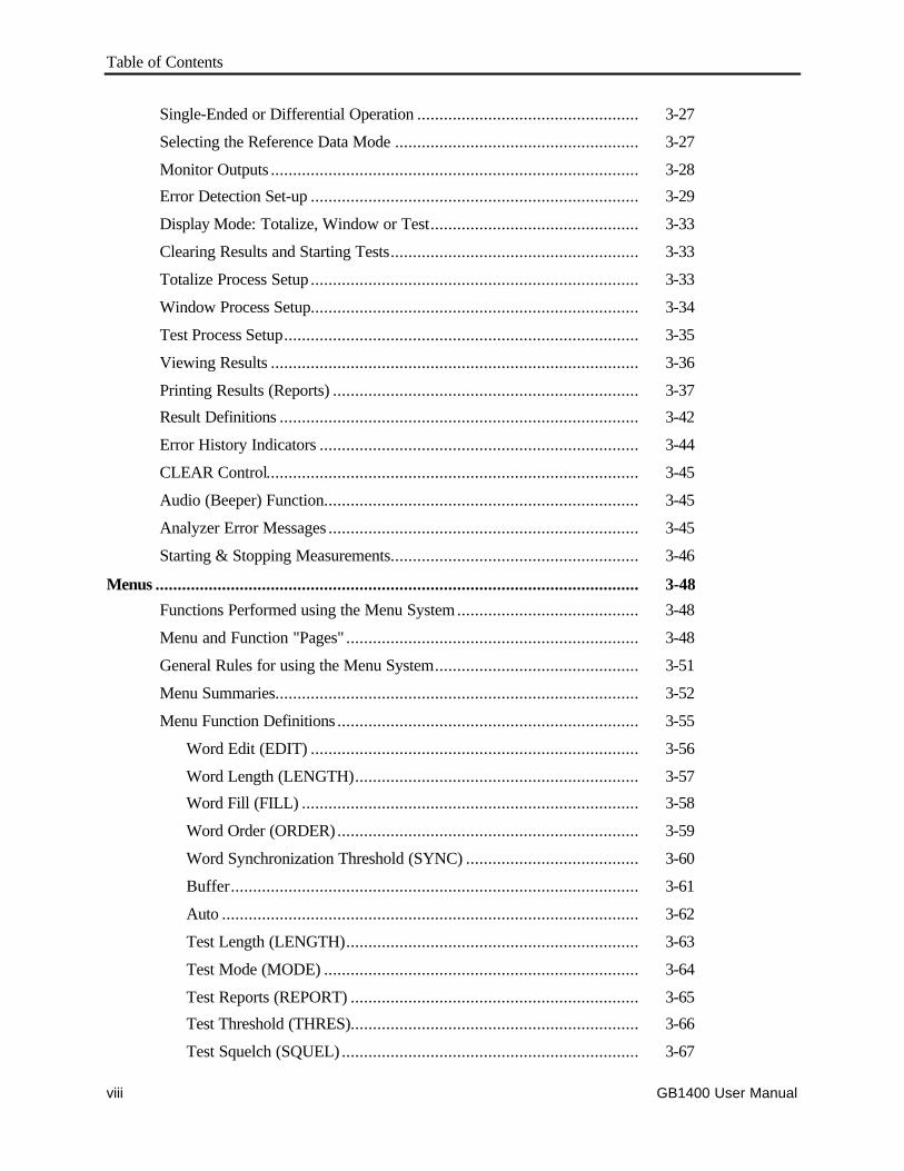
Table of Contents
GB1400 User Manualviii
Single-Ended or Differential Operation .................................................. 3-27
Selecting the Reference Data Mode ....................................................... 3-27
Monitor Outputs ................................................................................... 3-28
Error Detection Set-up .......................................................................... 3-29
Display Mode: Totalize, Window or Test............................................... 3-33
Clearing Results and Starting Tests........................................................ 3-33
Totalize Process Setup .......................................................................... 3-33
Window Process Setup.......................................................................... 3-34
Test Process Setup................................................................................ 3-35
Viewing Results ................................................................................... 3-36
Printing Results (Reports) ..................................................................... 3-37
Result Definitions ................................................................................. 3-42
Error History Indicators ........................................................................ 3-44
CLEAR Control.................................................................................... 3-45
Audio (Beeper) Function....................................................................... 3-45
Analyzer Error Messages ...................................................................... 3-45
Starting & Stopping Measurements........................................................ 3-46
Menus ............................................................................................................. 3-48
Functions Performed using the Menu System......................................... 3-48
Menu and Function "Pages" .................................................................. 3-48
General Rules for using the Menu System.............................................. 3-51
Menu Summaries.................................................................................. 3-52
Menu Function Definitions .................................................................... 3-55
Word Edit (EDIT) .......................................................................... 3-56
Word Length (LENGTH)................................................................ 3-57
Word Fill (FILL) ............................................................................ 3-58
Word Order (ORDER) .................................................................... 3-59
Word Synchronization Threshold (SYNC) ....................................... 3-60
Buffer............................................................................................ 3-61
Auto .............................................................................................. 3-62
Test Length (LENGTH).................................................................. 3-63
Test Mode (MODE) ....................................................................... 3-64
Test Reports (REPORT) ................................................................. 3-65
Test Threshold (THRES)................................................................. 3-66
Test Squelch (SQUEL) ................................................................... 3-67
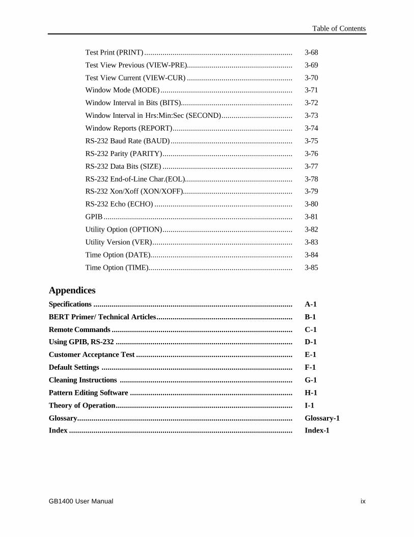
Table of Contents
GB1400 User Manual ix
Test Print (PRINT) ......................................................................... 3-68
Test View Previous (VIEW-PRE).................................................... 3-69
Test View Current (VIEW-CUR) .................................................... 3-70
Window Mode (MODE) ................................................................. 3-71
Window Interval in Bits (BITS)....................................................... 3-72
Window Interval in Hrs:Min:Sec (SECOND)................................... 3-73
Window Reports (REPORT)........................................................... 3-74
RS-232 Baud Rate (BAUD) ............................................................ 3-75
RS-232 Parity (PARITY)................................................................ 3-76
RS-232 Data Bits (SIZE) ................................................................ 3-77
RS-232 End-of-Line Char.(EOL)..................................................... 3-78
RS-232 Xon/Xoff (XON/XOFF)...................................................... 3-79
RS-232 Echo (ECHO) .................................................................... 3-80
GPIB ............................................................................................. 3-81
Utility Option (OPTION)................................................................ 3-82
Utility Version (VER)..................................................................... 3-83
Time Option (DATE)...................................................................... 3-84
Time Option (TIME)....................................................................... 3-85
AppendicesSpecifications .................................................................................................. A-1
BERT Primer/ Technical Articles................................................................... B-1
Remote Commands ......................................................................................... C-1
Using GPIB, RS-232 ....................................................................................... D-1
Customer Acceptance Test ............................................................................. E-1
Default Settings .............................................................................................. F-1
Cleaning Instructions ..................................................................................... G-1
Pattern Editing Software ................................................................................ H-1
Theory of Operation....................................................................................... I-1
Glossary.......................................................................................................... Glossary-1
Index .............................................................................................................. Index-1
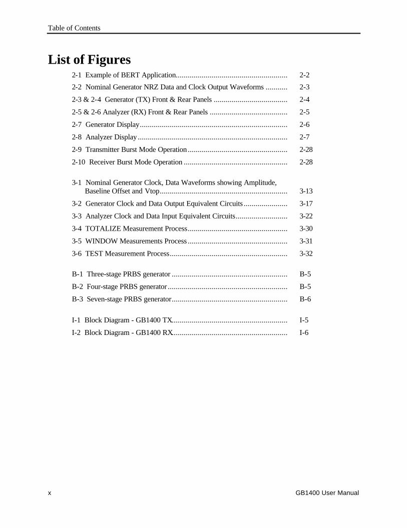
Table of Contents
GB1400 User Manualx
List of Figures2-1 Example of BERT Application........................................................ 2-2
2-2 Nominal Generator NRZ Data and Clock Output Waveforms ........... 2-3
2-3 & 2-4 Generator (TX) Front & Rear Panels ..................................... 2-4
2-5 & 2-6 Analyzer (RX) Front & Rear Panels ....................................... 2-5
2-7 Generator Display.......................................................................... 2-6
2-8 Analyzer Display ........................................................................... 2-7
2-9 Transmitter Burst Mode Operation .................................................. 2-28
2-10 Receiver Burst Mode Operation .................................................... 2-28
3-1 Nominal Generator Clock, Data Waveforms showing Amplitude, Baseline Offset and Vtop................................................................ 3-13
3-2 Generator Clock and Data Output Equivalent Circuits ...................... 3-17
3-3 Analyzer Clock and Data Input Equivalent Circuits.......................... 3-22
3-4 TOTALIZE Measurement Process.................................................. 3-30
3-5 WINDOW Measurements Process .................................................. 3-31
3-6 TEST Measurement Process........................................................... 3-32
B-1 Three-stage PRBS generator .......................................................... B-5
B-2 Four-stage PRBS generator ............................................................ B-5
B-3 Seven-stage PRBS generator.......................................................... B-6
I-1 Block Diagram - GB1400 TX.......................................................... I-5
I-2 Block Diagram - GB1400 RX.......................................................... I-6
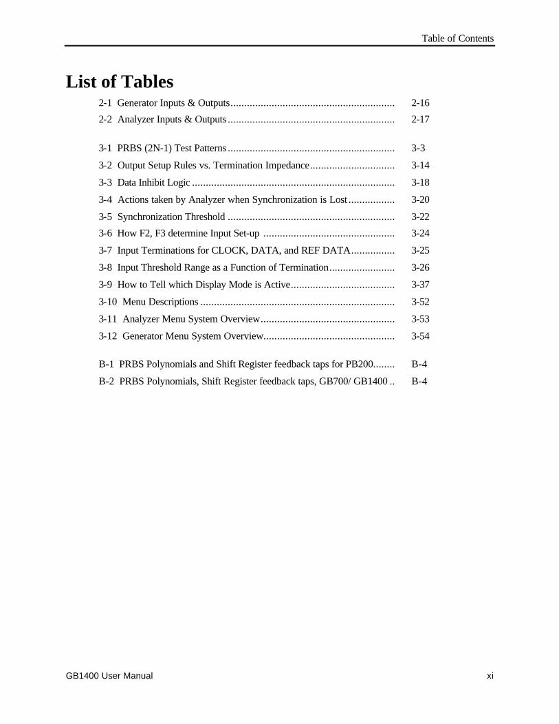
Table of Contents
GB1400 User Manual xi
List of Tables2-1 Generator Inputs & Outputs............................................................ 2-16
2-2 Analyzer Inputs & Outputs ............................................................. 2-17
3-1 PRBS (2N-1) Test Patterns ............................................................. 3-3
3-2 Output Setup Rules vs. Termination Impedance............................... 3-14
3-3 Data Inhibit Logic .......................................................................... 3-18
3-4 Actions taken by Analyzer when Synchronization is Lost ................. 3-20
3-5 Synchronization Threshold ............................................................. 3-22
3-6 How F2, F3 determine Input Set-up ................................................ 3-24
3-7 Input Terminations for CLOCK, DATA, and REF DATA................ 3-25
3-8 Input Threshold Range as a Function of Termination........................ 3-26
3-9 How to Tell which Display Mode is Active...................................... 3-37
3-10 Menu Descriptions ....................................................................... 3-52
3-11 Analyzer Menu System Overview................................................. 3-53
3-12 Generator Menu System Overview................................................ 3-54
B-1 PRBS Polynomials and Shift Register feedback taps for PB200........ B-4
B-2 PRBS Polynomials, Shift Register feedback taps, GB700/ GB1400 .. B-4
xii GB1400 User Manual
Safety
Safety Terms Used in This User's Guide
C A U T I O N ! Indicates an operation or practice that could harm theinstrument.
W A R N I N G ! Indicates an operation or practice that could result inpersonal injury or loss of life.
Safety Labels Found on the Instrument
DANGERHigh Voltage
Protective Ground(Earth) Terminal
ATTENTIONRefer to Manual
AC Power
The instrument is designed to operate from a power source that provides no morethan 250 volts RMS between the two supply conductors or between either supplyconductor and ground.
Ground the Instrument
The GB1400 is grounded through its AC power cord. Plug this power cord onlyinto a properly grounded, three-conductor outlet. If you operate the instrumentwithout a proper ground then all metal surfaces on the instrument becomepotential shock hazards.
To avoid potential hazards, use this product only as specified.
Use the Proper Fuse
Operating the instrument with an improper fuse creates a fire hazard. The correctfuses to install in the GB1400 are shown below:
Power Voltage Fuse Type115 VAC 5A, Slo-Blo230 VAC 5A, Slo-Blo
Do Not Operate in Explosive Atmospheres
This instrument does not provide protection from static discharges or arcingcomponents and therefore must not be operated in an explosive atmosphere.
Table of Contents
GB1400 User Manual xiii
Do Not Remove Instrument Covers
To avoid a shock hazard and to maintain proper air flow, never operate theGB1400 with any of its outside covers removed.
Static Sensitive Device Notice
GB1400 outputs use a GaAs FET design and therefore are susceptible to damagefrom externally applied over-voltage or electrostatic discharge. Never applyreverse voltage to DATA or CLOCK outputs or voltages that are outside therange specified in Appendix A of this manual. Operate the instrument only in astatic-controlled environment.
SMA Connectors
Be careful when attaching test cables to SMA connectors. Always tighten the nuton the SMA connector rather than the cable itself. Never tighten an SMAconnector nut using more than 10 lb.-in. of torque.
Behavior of Outputs - Turning Power On or Off
When the GB1400 Generator is powered or de-powered its DATA and CLOCKoutputs may saturate to their specified positive or negative rail, that is +2 V or - 2V, for up to 400 milliseconds. If this condition could be harmful to yourequipment, then remove all connections to your GB1400 Generator CLOCK andDATA outputs before powering or de-powering the instrument.
Unit Mounting
The GB1400 is designed to be placed: (1) flat on a level surface, capable ofsupporting its weight, or (2) angled from the surface with the rotating carryinghandle. To change the handle's orientation, press both handle-locking buttons(located at the hubs of the handle), rotate the handle to the desired angle, andrelease the buttons. The handle will click into a locked position. Assure that thehandle is locked before placing the unit on a work surface. A Rack mountingoption is available for installation of the unit into a 19" rackmount. The rackheight for the GB1400 is 7 inches (four RMU).
Unit Cooling
The rear panel fan openings and top-mounted ventilation slots must be kept clearfor proper cooling of the unit. Allow a minimum of two (2) inches of rear panelclearance, and one (1) inch of top clearance, while operating the unit.
xiv GB1400 User Manual
PrefaceThis manual describes how to use the Tektronix GB1400 Test Set. The product isalso known by the name, gigaBERT1400. This manual is your primary source ofinformation on how to use the GB1400 functions.
How This Manual is Organized
This manual is divided into four sections: Getting Started, Operating Basics,Reference, and Appendices.
Getting Started provides an overview of the GB1400 and describes first timeoperation.
Operating Basics describes the hardware controls, indicators, connectors, anddisplay elements for Tx, Rx and the cabling required. There is also a tutorial andan application note in this section.
Reference describes the LCD Menus and Screens.
The Appendices provide a listing of specifications, a BERT technology primer,Theory of Operation, Remote Commands, default factory settings, an extensiveCustomer Acceptance Test and other useful information.
Conventions
This manual uses the following conventions:
• The names of front-panel controls and menus appear in all upper case letters,for example, TRANSMIT and HELP.
• Names appear in the same case in this manual as they appear on the displayscreens of the GB1400.
• Within a procedure, a specific button to be pressed or a parameter to beselected appears in boldface print.
Some procedures require several iterations of highlighting parameters andselecting choices. Some procedures may require more than one menu button ormenu page selection as well.

Preface
GB1400 User Manual xv
Related Manuals
The following document is also complementary to the GB1400:
• The GB700 BER Tester User Manual (Tektronix part number070-9393-02) describes how to operate the GB700 test set.

Preface
GB1400 User Manualxvi

Getting Started
GB1400 User Manual 1-1
Getting Started
GB1400 Pattern Generator and Error Detector
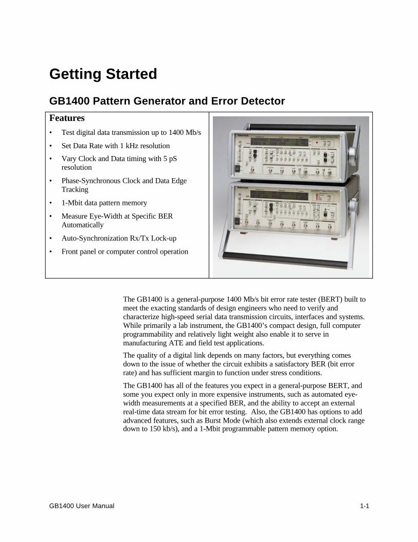
Features• Test digital data transmission up to 1400 Mb/s
• Set Data Rate with 1 kHz resolution
• Vary Clock and Data timing with 5 pSresolution
• Phase-Synchronous Clock and Data EdgeTracking
• 1-Mbit data pattern memory
• Measure Eye-Width at Specific BERAutomatically
• Auto-Synchronization Rx/Tx Lock-up
• Front panel or computer control operation
The GB1400 is a general-purpose 1400 Mb/s bit error rate tester (BERT) built tomeet the exacting standards of design engineers who need to verify andcharacterize high-speed serial data transmission circuits, interfaces and systems.While primarily a lab instrument, the GB1400’s compact design, full computerprogrammability and relatively light weight also enable it to serve inmanufacturing ATE and field test applications.
The quality of a digital link depends on many factors, but everything comesdown to the issue of whether the circuit exhibits a satisfactory BER (bit errorrate) and has sufficient margin to function under stress conditions.
The GB1400 has all of the features you expect in a general-purpose BERT, andsome you expect only in more expensive instruments, such as automated eye-width measurements at a specified BER, and the ability to accept an externalreal-time data stream for bit error testing. Also, the GB1400 has options to addadvanced features, such as Burst Mode (which also extends external clock rangedown to 150 kb/s), and a 1-Mbit programmable pattern memory option.
Getting Started
1-2 GB1400 User Manual
Symmetrical, Low-Jitter Output Waveforms
The GB1400 generates low-jitter, symmetrical waveforms over its entireoperating frequency range. The clock and data ports provide both true andinverted output signals. The instrument can drive single-ended or differentialECL inputs.
Applications
The GB1400 is focused on the research, design, and manufacturing oftelecommunication components, modules, or links operating at data rates to1400 Mb/s. It is frequently employed in testing and development well under thistop speed rating, where sharp clock and data waveforms are especially desired, orwhere additional frequency range is thought to be needed in the future.
Sample Applications
• Development of Gigabit LAN/Data Comm Devices:
• High-Speed Fibre Channel, Ethernet
• Digital Video (MPEG, SDV, HDDV)
• Wideband Satellite Data Links
• SONET/SDH Network Devices up to OC-12e/STM4e
• High-speed GaAs/ECL/E/O device testing
• Test Clock Recovery Circuits
• Parallel-to-Serial Analysis with Tektronix MB100
• Testing of High Speed Fibre Channel links up to 1,063 Mb/s
• Gigabit Ethernet at 1,250 Mb/s.
• Testing of high-speed Optical Busses (Opto Bus, Opto Bahn) at 800 Mb/s perchannel.
• Satellite system testing and TDMA (Burst Mode) at 400, 800 Mb/s
• GaAs, ECL and optical component testing
PRBS Or User-Defined Test Patterns
The GB1400 can generate pseudo-random bit sequences (PRBS) up to 223−1 bitsand others up to 1-Mbit in length, via user-programmable patterns. Patterns canbe created locally using setup menus or externally by using a workstation or PC.A PC Windows-based MLPE Pattern Editor software package comes with the1-Mbit Memory Option. Externally created patterns can be downloaded via theGPIB or RS-232 port. All user patterns are saved in battery-backed RAM.
Getting Started
GB1400 User Manual 1-3
Adjustable Inputs For Maximum Flexibility
The clock and data ports on the GB1400 Error Detector accept both true andinverted inputs. Single-ended or differential signals can be internally terminated.Input data delay is adjustable over a 4 ns range to accommodate different clockand data signal path delays.
Auto Search For Easy Setup
Auto search greatly simplifies the Error Detector setup. The GB1400 ErrorDetector automatically synchronizes to the incoming signal by 1) Setting theinput data decision voltage to its optimum value; 2) Adjusting input data delayfor an optimum clock/data phase relationship; 3) Selecting the correct PRBS testpattern; and 4) selecting the correct pattern polarity (normal or inverted).
It synchronizes with any pattern sourced by a gigaBERT Pattern Generator. Itcan perform a bit-by-bit comparison of an external data stream via the ReferenceData input. Thus the GB1400 can perform bit error analysis on any data patternwith a known good reference pattern.
Powerful Analysis And Reporting Functions
The GB1400 performs a full-rate, bit-by-bit analysis of the received signal. Biterror results are then used to calculate three bit error rate (BER) measures. TotalBER is calculated from the last power-on or reset. Window BER is calculatedover a sliding window specified in terms of time (1 second to 24 hours) or bits(18- to 116-bits). Test BER is calculated from the start of the current test. A hardcopy of all test results can be generated locally by connecting a printer to theparallel printer port or GPIB or RS-232 port. Reports may be printed when anerror is detected, at the end of test intervals, or both.
Front Panel Or Automated Operation
The GB1400 provides easy operation augmented by set-up store and recall.Clear, concise LCD displays of setup and results make it easy to use. The 1Megabit memory option for both the Pattern Generator and the Error Detector issufficient for storing and outputting complex data such as SONET frames, ATMcells, MPEG digital video, etc, allowing designers to simulate “live” traffic. TheGB1400 Pattern Generator and Error Detector can be controlled via the GPIB orRS-232 interface ports. The gigaBERT remote command set includes commandsfor all setup menus and front panel selections. The status of front panel indicatorsand test results can be remotely accessed.
Burst Mode
BURST mode, allows for operation with non-continuous external clocks. Use ofBURST mode requires ECL-level signals with a minimum rate during the burstof 150 kHz. This is an option to the GB1400. See a write-up on Burst Mode atthe end of the Functional Overview section of Chapter 2.
Getting Started
1-4 GB1400 User Manual
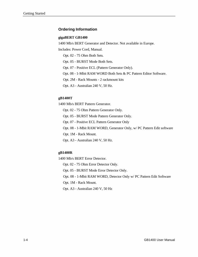
Ordering Information
gigaBERT GB1400
1400 Mb/s BERT Generator and Detector. Not available in Europe.
Includes: Power Cord, Manual.
Opt. 02 - 75 Ohm Both Sets.
Opt. 05 - BURST Mode Both Sets.
Opt. 07 - Positive ECL (Pattern Generator Only).
Opt. 08 - 1-Mbit RAM WORD Both Sets & PC Pattern Editor Software.
Opt. 2M - Rack Mounts - 2 rackmount kits
Opt. A3 - Australian 240 V, 50 Hz.
gB1400T
1400 Mb/s BERT Pattern Generator.
Opt. 02 - 75 Ohm Pattern Generator Only.
Opt. 05 - BURST Mode Pattern Generator Only.
Opt. 07 - Positive ECL Pattern Generator Only
Opt. 08 - 1-Mbit RAM WORD, Generator Only, w/ PC Pattern Edit software
Opt. 1M - Rack Mount.
Opt. A3 - Australian 240 V, 50 Hz.
gB1400R
1400 Mb/s BERT Error Detector.
Opt. 02 - 75 Ohm Error Detector Only.
Opt. 05 - BURST Mode Error Detector Only.
Opt. 08 - 1-Mbit RAM WORD, Detector Only w/ PC Pattern Edit Software
Opt. 1M - Rack Mount.
Opt. A3 - Australian 240 V, 50 Hz
Getting Started
GB1400 User Manual 1-5
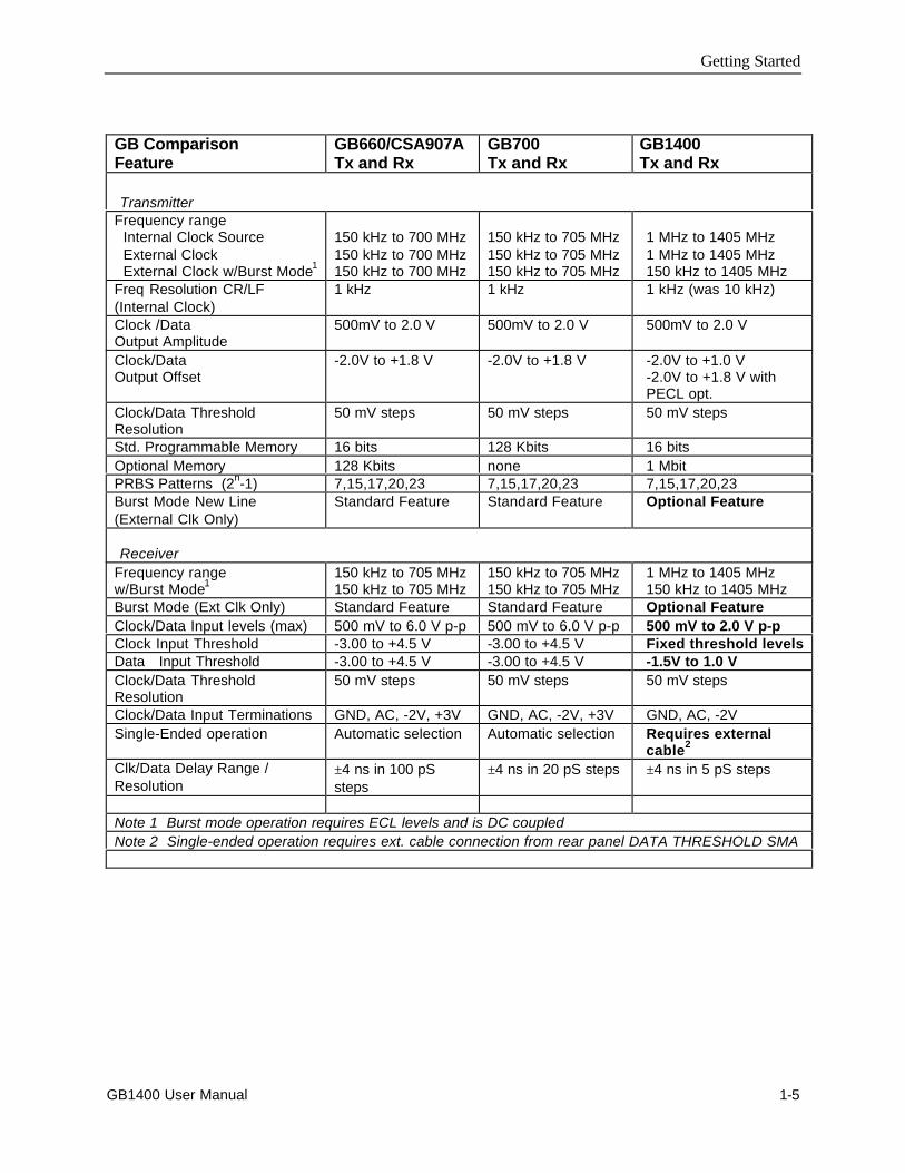
GB ComparisonFeature
GB660/CSA907ATx and Rx
GB700Tx and Rx
GB1400Tx and Rx
TransmitterFrequency range Internal Clock Source External Clock External Clock w/Burst Mode1
150 kHz to 700 MHz150 kHz to 700 MHz150 kHz to 700 MHz
150 kHz to 705 MHz150 kHz to 705 MHz150 kHz to 705 MHz
1 MHz to 1405 MHz1 MHz to 1405 MHz150 kHz to 1405 MHz
Freq Resolution CR/LF(Internal Clock)
1 kHz 1 kHz 1 kHz (was 10 kHz)
Clock /DataOutput Amplitude
500mV to 2.0 V 500mV to 2.0 V 500mV to 2.0 V
Clock/DataOutput Offset
-2.0V to +1.8 V -2.0V to +1.8 V -2.0V to +1.0 V-2.0V to +1.8 V withPECL opt.
Clock/Data ThresholdResolution
50 mV steps 50 mV steps 50 mV steps
Std. Programmable Memory 16 bits 128 Kbits 16 bitsOptional Memory 128 Kbits none 1 MbitPRBS Patterns (2n-1) 7,15,17,20,23 7,15,17,20,23 7,15,17,20,23Burst Mode New Line(External Clk Only)
Standard Feature Standard Feature Optional Feature
ReceiverFrequency rangew/Burst Mode1
150 kHz to 705 MHz150 kHz to 705 MHz
150 kHz to 705 MHz150 kHz to 705 MHz
1 MHz to 1405 MHz150 kHz to 1405 MHz
Burst Mode (Ext Clk Only) Standard Feature Standard Feature Optional FeatureClock/Data Input levels (max) 500 mV to 6.0 V p-p 500 mV to 6.0 V p-p 500 mV to 2.0 V p-pClock Input Threshold -3.00 to +4.5 V -3.00 to +4.5 V Fixed threshold levelsData Input Threshold -3.00 to +4.5 V -3.00 to +4.5 V -1.5V to 1.0 VClock/Data ThresholdResolution
50 mV steps 50 mV steps 50 mV steps
Clock/Data Input Terminations GND, AC, -2V, +3V GND, AC, -2V, +3V GND, AC, -2VSingle-Ended operation Automatic selection Automatic selection Requires external
cable2
Clk/Data Delay Range /Resolution
±4 ns in 100 pSsteps
±4 ns in 20 pS steps ±4 ns in 5 pS steps
Note 1 Burst mode operation requires ECL levels and is DC coupledNote 2 Single-ended operation requires ext. cable connection from rear panel DATA THRESHOLD SMA

Getting Started
1-6 GB1400 User Manual
GB1400 Instrument Configurations - Standard and Burst Option
GB1400 instruments are sold with and without the BURST option. To determine if the burst option isinstalled in a GB1400, press the F1 key several times until you get to the UTIL menu. Then select theOPTION menu. The OPTIONS menu will tell you if the Burst option is installed in the unit. Externalindications of the BURST option are unique labels for both transmitter and receiver. See a write-up onBurst Mode at the end of the Functional Overview section of Chapter 2.
GB1400 with no Burst Option Standard instrument configuration
All standard configuration GB1400 Generators (no burst option) have an AC coupled external clockinput. All standard configuration GB1400 Analyzers (no burst option) have AC coupled paths in thereceiver clock input circuitry.
GB1400 with Burst Option
When the BURST option is installed in the GB1400, the AC coupled paths in both transmitter andreceiver are eliminated. This will also change several specifications listed in the table below. Externalclock inputs to the GB1400 transmitter must be ECL levels when the BURST option is installed. Clockinputs into the GB1400 receiver must be ECL levels and are terminated into 50 Ohms to -2V.
GB1400 Clock Signals for Standard and Burst and Instruments
Standard Coupling Burst (Option) Coupling
GB1400 TX
External Clock Input 50 Ohm, AC coupled,2V max
50 Ohm to -2V, DC coupled,ECL levels
GB1400 RX
Clock Input 50 Ohm, AC coupled,2.0V max
50 Ohm to -2V, DC coupled,ECL levels

Getting Started
GB1400 User Manual 1-7
Initial Self-Check Procedure
You may perform the following procedure as an initial self-check of yourGB1400 Generator and Analyzer. It is also a useful introduction to the basicfeatures and operation of the GB1400.
The fan openings of the GB1400 needs 2-inches of clearance for properventilation.
Procedure
1. Make sure both the Generator and Analyzer are equipped with the properfuse.
2. Make sure that the Generator and Analyzer rear-panel power switchesare ON, and that their front-panel power switches are in the STBYposition.
3. Plug both instruments into grounded (three-conductor) AC power outlets.
4. Connect a 50-Ohm SMA cable from the Generator CLOCK output to theAnalyzer CLOCK input. If using 75-Ohm option, use &5 OHMSMA/BNC cable.
5. Connect a 50-Ohm SMA cable from the Generator DATA output to theAnalyzer DATA input.
6. Connect a 50-Ohm SMA cable from the Analyzer rear panel DATATHRESHOLD output to the Analyzer DATA BAR input (required forsingle-ended data inputs).
7. Power the Generator while pressing and holding its VIEW ANGLE,MSB 1 and (PATTERN) CLEAR keys simultaneously. Release the keyafter the message Default Settings appears in the display. Repeat thisprocedure with the Analyzer. This will force both the Generator andAnalyzer to power up using factory default settings.
8. Set up the Generator clock and data outputs using controls in theOUTPUT box as follows:
Set this parameter… to this value … using this procedure.DATA amplitude. 2 volts Press the DATA key.
Press AMPLITUDE up/down keys untildata amplitude is set to 2.00V.
DATA baseline offset -1 volt Press BASELINE OFFSET up/down keysuntil data baseline offset is set to -1.00V.
CLOCK amplitude 2 volts Press CLOCK.Press AMPLITUDE up/down keys untilclock amplitude is set to 2.00V.
CLOCK baseline offset -1 volt Press BASELINE OFFSET up/down keysuntil clock baseline OFFSET is set to-1.00V.

Getting Started
1-8 GB1400 User Manual
9. Set Generator pattern to a 223-1 bit PRBS using controls in thePATTERN box as follows:
a. Press PRBS.
b. Press the pattern up/down keys until PATTERN is set to PN 23.
10. Verify that the Generator error injection rate is off. If the LED in theerror inject RATE key is on, then press RATE one or more times until itturns off.
11. Verify that the Analyzer auto-search function is enabled. If the LED inthe AUTO SEARCH key is off, then press AUTO SEARCH one time toturn it on. At this point, verify that the green LOCK LED in theAnalyzer SYNC box is on.
12. Zero all Analyzer error counts by pressing CLEAR in the ERRORDETECTION group.
13. Reset all Analyzer history LEDs by pressing CLEAR in the ERRORHISTORY group.
14. Verify GB1400 Analyzer can detect errors by pressing the Generatorerror inject SINGLE key several times. Verify that the Number of Errorscount displayed by the Analyzer increments each time the GeneratorSINGLE key is pressed.
In effect you are now performing a bit error rate test on the test cables connectingthe GB1400 Generator and Analyzer. In an actual BER test, GB1400 Generatorclock and data outputs would be connected to inputs on a "device under test"(DUT) while GB1400 Analyzer inputs would be connected to outputs on theDUT.
Operating Basics
GB1400 User Manual 2-1
Functional OverviewThis section describes how to use and navigate through the basic functions of theGB1400, including:
• BERT Basics
• Controls, indicators and connectors
• Display Formats
• Outputs and Inputs
Also in this section is:
• Tutorial - "Understand GB1400 instrument setup for BER testing usingPRBS patterns";
• Application Note - Auto Search Synchronization with GB1400; and,
• Application Example - GB700/ GB1400 Optical component test.
Functional Overview
2-2 GB1400 User Manual
BERT Basics - GB1400
The GB1400 Generator and Analyzer together comprise a 1400 Mb/s, serial, biterror rate test system or BERT.
A BERT is an instrument designed to measure the bit error rate (BER)—or moregenerally, the error performance—of a digital communications device, module, orsystem.
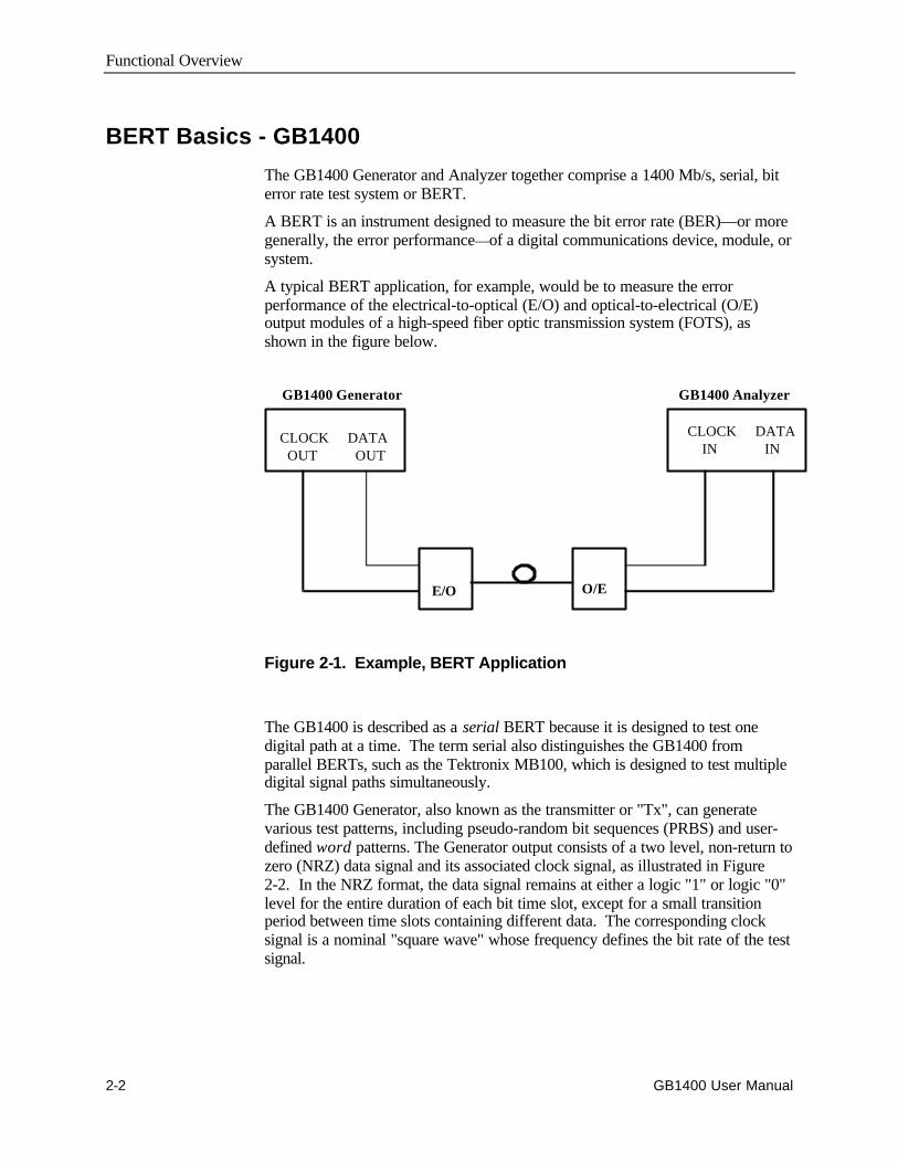
A typical BERT application, for example, would be to measure the errorperformance of the electrical-to-optical (E/O) and optical-to-electrical (O/E)output modules of a high-speed fiber optic transmission system (FOTS), asshown in the figure below.
Figure 2-1. Example, BERT Application
The GB1400 is described as a serial BERT because it is designed to test onedigital path at a time. The term serial also distinguishes the GB1400 fromparallel BERTs, such as the Tektronix MB100, which is designed to test multipledigital signal paths simultaneously.
The GB1400 Generator, also known as the transmitter or "Tx", can generatevarious test patterns, including pseudo-random bit sequences (PRBS) and user-defined word patterns. The Generator output consists of a two level, non-return tozero (NRZ) data signal and its associated clock signal, as illustrated in Figure2-2. In the NRZ format, the data signal remains at either a logic "1" or logic "0"level for the entire duration of each bit time slot, except for a small transitionperiod between time slots containing different data. The corresponding clocksignal is a nominal "square wave" whose frequency defines the bit rate of the testsignal.
GB1400 Generator GB1400 Analyzer
CLOCK DATA OUT OUT
CLOCK DATA IN IN
E/O O/E

Functional Overview
GB1400 User Manual 2-3
DATA
CLOCK
Falling edge of CLOCK in middle of DATA "eye"
Rising edge of CLOCK Coin-cident with DATA transitions
Figure 2-2. Nominal Generator NRZ Data and Clock OutputWaveforms
The nominal Generator clock/data phase relationship is fixed so that the fallingedges of the clock signal occur in the middle of bit time slots of the data signal.The amplitude and baseline offset of the Generator's clock and data outputs areadjustable to insure compatibility with a wide range of input circuit designs andlogic families including ECL, positive ECL, and GaAs.
The GB1400 Analyzer, also known as the receiver or "Rx", can terminate andanalyze the NRZ output of a digital device, module, or system being tested by theGB1400 Generator or an equivalent signal source. The decision voltage orthreshold of the Analyzer DATA and CLOCK inputs can be adjusted toaccommodate different logic families. The Analyzer can also add a variableamount of delay to the input data signal to accommodate different clock/dataphase relationships at the output of the device under test.
The primary measurements made by the GB1400 Analyzer are bit errors and biterror rate.
Functional Overview
2-4 GB1400 User Manual
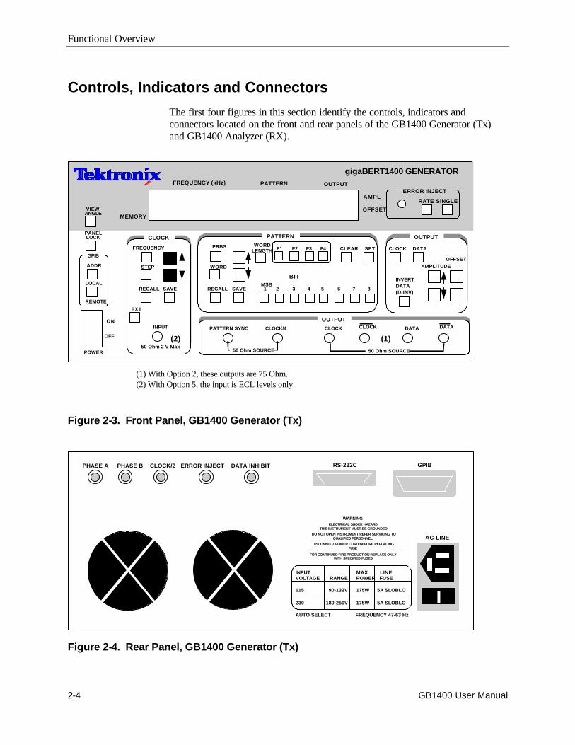
Controls, Indicators and Connectors
The first four figures in this section identify the controls, indicators andconnectors located on the front and rear panels of the GB1400 Generator (Tx)and GB1400 Analyzer (RX).
Figure 2-3. Front Panel, GB1400 Generator (Tx)
RS-232C
AC-LINE
GPIB
WARNINGELECTRICAL SHOCK HAZARD
THIS INSTRUMENT MUST BE GROUNDED
DO NOT OPEN INSTRUMENT REFER SERVICING TOQUALIFIED PERSONNEL
DISCONNECT POWER CORD BEFORE REPLACINGFUSE
FOR CONTINUED FIRE PRODUCTION REPLACE ONLYWITH SPECIFIED FUSES
INPUT MAX LINEVOLTAGE RANGE POWER FUSE
115 90-132V 175W 5A SLOBLO
230 180-250V 175W 5A SLOBLO
AUTO SELECT FREQUENCY 47-63 Hz
PHASE A PHASE B CLOCK/2 ERROR INJECT DATA INHIBIT
Figure 2-4. Rear Panel, GB1400 Generator (Tx)
FREQUENCY (kHz) PATTERN OUTPUT
AMPL
OFFSET
RATE SINGLE
CLOCK PATTERN OUTPUT
OUTPUT
ERROR INJECT
FREQUENCY
STEP
RECALL SAVE
EXT
PRBS
WORD
RECALL SAVE
F1 F2 F3 F4
MSB 1 2 3 4 5 6 7 8
CLEAR SET CLOCK DATA
AMPLITUDEOFFSET
INVERTDATA(D-INV)
PATTERN SYNC CLOCK/4 CLOCK CLOCK DATA DATA
50 Ohm SOURCE
gigaBERT1400 GENERATOR
INPUT
50 Ohm 2 V Max
WORDLENGTH
50 Ohm SOURCE
PANELLOCK
VIEWANGLE
GPIB
ADDR
LOCAL
REMOTE
ON
OFF
POWER
MEMORY
(1) With Option 2, these outputs are 75 Ohm.(2) With Option 5, the input is ECL levels only.
(2) (1)
BIT
Functional Overview
GB1400 User Manual 2-5
FREQUENCY (kHz) ERROR RATE TOTALIZE
CLEAR
INPUT PATTERN ERROR DETECTION
DELAY
V-TERM V-THRESH
D-INV
PRBS
WORD
RECALL SAVE
F1 F2 F3 F4
MSB 1 2 3 4 5 6 7 8
CLEAR SET DISPLAYCLEAR
LOCK
DISABLE
PATTERNSYNC
CLOCK DATA
gigaBERT 1400 ANALYZER
DATA DATA
SYNC LOSSBITPHASEPOWER
VOL RATEAUDIO
AUTOSEARCH
SYNCWORD
LENGTH
EXT
REFERENCE DATA CLOCK CLOCKMONITOR
ERROR HISTORY
PANELLOCK
VIEWANGLE
GPIB
ADDR
LOCAL
REMOTE
ON
OFF
POWER 50 Ohm SOURCE 50 Ohm, 1.5V MAX 50 Ohm, 2V MAX
DELAY/MEMORY
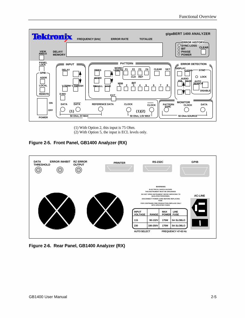
(1) With Option 2, this input is 75 Ohm.(2) With Option 5, the input is ECL levels only.
(1) (2)(1)
BIT
CLK REF
Figure 2-5. Front Panel, GB1400 Analyzer (RX)
PRINTERDATATHRESHOLD
ERROR INHIBIT RZ ERROROUTPUT
RS-232C GPIB
AC-LINE
WARNING
ELECTRICAL SHOCK HAZARDTHIS INSTRUMENT MUST BE GROUNDED
DO NOT OPEN INSTRUMENT REFER SERVICING TOQUALIFIED PERSONNEL
DISCONNECT POWER CORD BEFORE REPLACINGFUSE
FOR CONTINUED FIRE PRODUCTION REPLACE ONLYWITH SPECIFIED FUSES
INPUT MAX LINEVOLTAGE RANGE POWER FUSE
115 90-132V 175W 5A SLOBLO
230 180-250V 175W 5A SLOBLO
AUTO SELECT FREQUENCY 47-63 Hz
Figure 2-6. Rear Panel, GB1400 Analyzer (RX)
Functional Overview
2-6 GB1400 User Manual
Display Formats
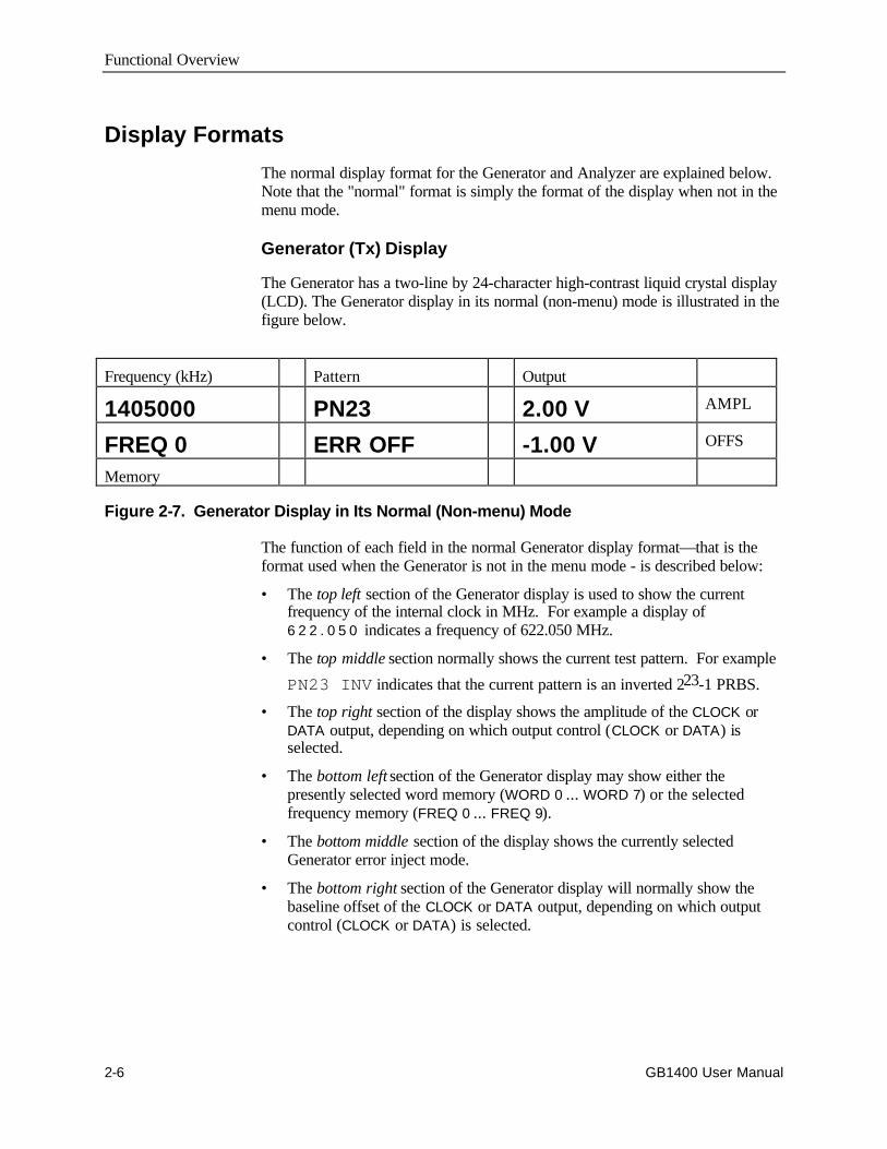
The normal display format for the Generator and Analyzer are explained below.Note that the "normal" format is simply the format of the display when not in themenu mode.
Generator (Tx) Display
The Generator has a two-line by 24-character high-contrast liquid crystal display(LCD). The Generator display in its normal (non-menu) mode is illustrated in thefigure below.
Frequency (kHz) Pattern Output
1405000 PN23 2.00 V AMPL
FREQ 0 ERR OFF -1.00 V OFFS
Memory
Figure 2-7. Generator Display in Its Normal (Non-menu) Mode
The function of each field in the normal Generator display format—that is theformat used when the Generator is not in the menu mode - is described below:
• The top left section of the Generator display is used to show the currentfrequency of the internal clock in MHz. For example a display of6 2 2 . 0 5 0 indicates a frequency of 622.050 MHz.
• The top middle section normally shows the current test pattern. For example
PN23 INV indicates that the current pattern is an inverted 223-1 PRBS.
• The top right section of the display shows the amplitude of the CLOCK orDATA output, depending on which output control (CLOCK or DATA) isselected.
• The bottom left section of the Generator display may show either thepresently selected word memory (WORD 0 ... WORD 7) or the selectedfrequency memory (FREQ 0 ... FREQ 9).
• The bottom middle section of the display shows the currently selectedGenerator error inject mode.
• The bottom right section of the Generator display will normally show thebaseline offset of the CLOCK or DATA output, depending on which outputcontrol (CLOCK or DATA) is selected.
Functional Overview
GB1400 User Manual 2-7
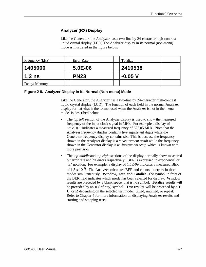
Analyzer (RX) Display
Like the Generator, the Analyzer has a two-line by 24-character high-contrastliquid crystal display (LCD).The Analyzer display in its normal (non-menu)mode is illustrated in the figure below.
Frequency (kHz) Error Rate Totalize
1405000 5.0E-06 2410538
1.2 ns PN23 -0.05 VDelay/ Memory
Figure 2-8. Analyzer Display in Its Normal (Non-menu) Mode
Like the Generator, the Analyzer has a two-line by 24-character high-contrastliquid crystal display (LCD). The function of each field in the normal Analyzerdisplay format -that is the format used when the Analyzer is not in the menumode -is described below:
• The top left section of the Analyzer display is used to show the measuredfrequency of the input clock signal in MHz. For example a display of6 2 2 . 0 5 indicates a measured frequency of 622.05 MHz. Note that theAnalyzer frequency display contains five significant digits while theGenerator frequency display contains six. This is because the frequencyshown in the Analyzer display is a measurement result while the frequencyshown in the Generator display is an instrument setup which is known withmore precision.
• The top middle and top right sections of the display normally show measuredbit error rate and bit errors respectively. BER is expressed in exponential or"E" notation. For example, a display of 1.5E-09 indicates a measured BERof 1.5 x 10⁻⁹. The Analyzer calculates BER and counts bit errors in threemodes simultaneously: Window, Test, and Totalize. The symbol in front ofthe BER field indicates which mode has been selected for display. Windowresults are preceded by a blank space, that is no symbol. Totalize results willbe preceded by an ∞ (infinity) symbol. Test results will be preceded by a T,U, or R depending on the selected test mode: timed, untimed, or repeat.Refer to Chapter 4 for more information on displaying Analyzer results andstarting and stopping tests.

Functional Overview
2-8 GB1400 User Manual
• The bottom left section of the Analyzer display can show the following setupparameters: delay in nanoseconds for the DATA or REF DATA input; theselected input termination (GND, -2V, or AC) for the CLOCK, DATA, orREFERENCE DATA input, or the selected word memory (WORD 0 ...WORD 7), Note that DATA input delay may be set manually by the user, orautomatically by the AUTO SEARCH feature.
To control the delay, termination or threshold settings for the DATA input,make sure F2 and F3 LEDs are turned OFF.
Pressing F2 places the unit into CLOCK control (F2 LED illuminated). TheV-TERM key is redefined to allow control of the Input CLOCK Terminationvoltage. The status of each key LED and LCD displayed value now reflectsthe CLOCK Input signal.
Pressing F3 places the unit into REF Data control mode (F3 LEDilluminated). The Delay, V-TERM and V-THRS keys are redefined to allowcontrol of the Input REF DATA Delay, Termination Volga and Threshold.The status of each key LED and LCD displayed value now reflects the REFDATA Input signal.
• The bottom middle section of the display shows the currently selectedAnalyzer pattern, for example PN23 indicates a 223-1 PRBS. This sectionwill also indicate when input pattern inversion is enabled by displaying INVafter the pattern name.
• The bottom right section of the Analyzer display shows the current value ofthe input threshold in volts for the CLOCK, DATA, or REF DATA inputs.Note that the CLOCK and DATA input thresholds may be set manually bythe user, or automatically by the AUTO SEARCH feature.
Functional Overview
GB1400 User Manual 2-9
Outputs and Inputs
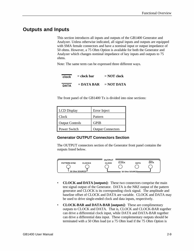
This section introduces all inputs and outputs of the GB1400 Generator andAnalyzer. Unless otherwise indicated, all signal inputs and outputs are equippedwith SMA female connectors and have a nominal input or output impedance of50 ohms. However, a 75 Ohm Option is available for both the Generator andAnalyzer which changes nominal impedance of key inputs and outputs to 75ohms.
Note: The same term can be expressed three different ways.
clock = clock bar = NOT clock
DATA = DATA BAR = NOT DATA
The front panel of the GB1400 Tx is divided into nine sections:
LCD Display Error Inject
Clock Pattern
Output Controls GPIB
Power Switch Output Connectors
Generator OUTPUT Connectors Section
The OUTPUT connectors section of the Generator front panel contains theoutputs listed below.
• CLOCK and DATA [outputs]: These two connectors comprise the maintest signal output of the Generator. DATA is the NRZ output of the patterngenerator and CLOCK is its corresponding clock signal. The amplitude andbaseline offset of CLOCK and DATA are variable. CLOCK and DATA maybe used to drive single-ended clock and data inputs, respectively.
• CLOCK-BAR and DATA-BAR [outputs]: These are complimentaryoutputs to CLOCK and DATA. That is, CLOCK and CLOCK-BAR togethercan drive a differential clock input, while DATA and DATA-BAR togethercan drive a differential data input. These complementary outputs should beterminated with a 50 Ohm load (or a 75 Ohm load if the 75 Ohm Option is
OUTPUTPATTERN SYNC CLOCK/4 CLOCK CLOCK DATA DATA
50 Ohm SOURCE 50 Ohm SOURCE
Functional Overview
2-10 GB1400 User Manual
installed) when not in use—that is, when the Generator is driving single-ended inputs.
• CLOCK/4 [output]: This is a clock signal at one quarter the frequency ofCLOCK. This output may be useful when observing generator outputs usingan oscilloscope that does not have the bandwidth to trigger on the CLOCKoutput.
• PATTERN SYNC [output]: This is a pulse that occurs once per patternframe. This output may be useful as a trigger signal when observing theGenerator data output using an oscilloscope. The location of PATTERNSYNC is fixed. A pulse is generated at the start of the pattern frame.
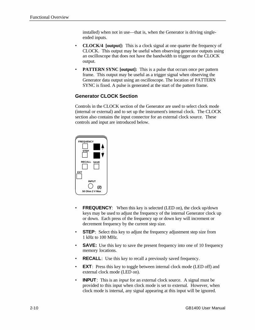
Generator CLOCK Section
Controls in the CLOCK section of the Generator are used to select clock mode(internal or external) and to set up the instrument's internal clock. The CLOCKsection also contains the input connector for an external clock source. Thesecontrols and input are introduced below.
FREQUENCY
STEP
RECALL SAVE
EXT
INPUT
50 Ohm 2 V Max
(2)
• FREQUENCY: When this key is selected (LED on), the clock up/downkeys may be used to adjust the frequency of the internal Generator clock upor down. Each press of the frequency up or down key will increment ordecrement frequency by the current step size.
• STEP: Select this key to adjust the frequency adjustment step size from1 kHz to 100 MHz.
• SAVE: Use this key to save the present frequency into one of 10 frequencymemory locations.
• RECALL: Use this key to recall a previously saved frequency.
• EXT: Press this key to toggle between internal clock mode (LED off) andexternal clock mode (LED on).
• INPUT : This is an input for an external clock source. A signal must beprovided to this input when clock mode is set to external. However, whenclock mode is internal, any signal appearing at this input will be ignored.

Functional Overview
GB1400 User Manual 2-11
Generator OUTPUT Section
The controls shown below are used to set up the Generator's clock and dataoutputs.
• CLOCK: Use this key to select clock amplitude and offset set up mode.
• DATA: Use this key to select data amplitude and offset set up mode.
• AMPLITUDE (↑↑ , ↓↓ ): Use these up/down keys to adjust clock or dataoutput amplitude.
• BASELINE OFFSET (↑↑ , ↓↓ ): Use these up/down keys to adjust clock ordata baseline offset.
• INVERT DATA: Use this key to toggle between output data inverted (LEDon) and non-inverted (LED off) mode.
OUTPUT
CLOCK DATA
AMPLITUDEOFFSET
INVERTDATA(D-INV)
Functional Overview
2-12 GB1400 User Manual
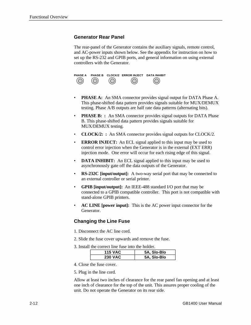
Generator Rear Panel
The rear-panel of the Generator contains the auxiliary signals, remote control,and AC-power inputs shown below. See the appendix for instruction on how toset up the RS-232 and GPIB ports, and general information on using externalcontrollers with the Generator.
• PHASE A: An SMA connector provides signal output for DATA Phase A.This phase-shifted data pattern provides signals suitable for MUX/DEMUXtesting. Phase A/B outputs are half rate data patterns (alternating bits).
• PHASE B: : An SMA connector provides signal outputs for DATA PhaseB. This phase-shifted data pattern provides signals suitable forMUX/DEMUX testing.
• CLOCK/2: : An SMA connector provides signal outputs for CLOCK/2.
• ERROR INJECT: An ECL signal applied to this input may be used tocontrol error injection when the Generator is in the external (EXT ERR)injection mode. One error will occur for each rising edge of this signal.
• DATA INHIBIT: An ECL signal applied to this input may be used toasynchronously gate off the data outputs of the Generator.
• RS-232C [input/output]: A two-way serial port that may be connected toan external controller or serial printer.
• GPIB [input/output]: An IEEE-488 standard I/O port that may beconnected to a GPIB compatible controller. This port is not compatible withstand-alone GPIB printers.
• AC LINE [power input]: This is the AC power input connector for theGenerator.
Changing the Line Fuse
1. Disconnect the AC line cord.
2. Slide the fuse cover upwards and remove the fuse.
3. Install the correct line fuse into the holder.115 VAC 5A, Slo-Blo230 VAC 5A, Slo-Blo
4. Close the fuse cover.
5. Plug in the line cord.
Allow at least two inches of clearance for the rear panel fan opening and at leastone inch of clearance for the top of the unit. This assures proper cooling of theunit. Do not operate the Generator on its rear side.
PHASE A PHASE B CLOCK/2 ERROR INJECT DATA INHIBIT
Functional Overview
GB1400 User Manual 2-13
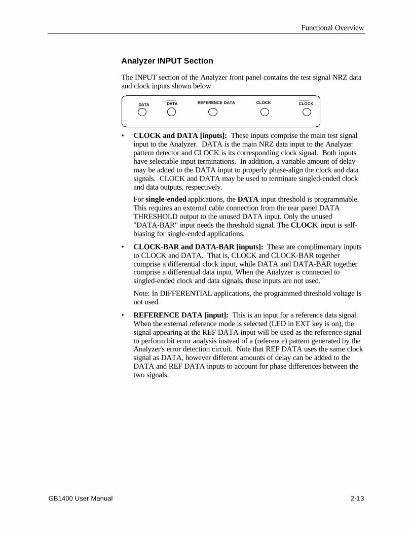
Analyzer INPUT Section
The INPUT section of the Analyzer front panel contains the test signal NRZ dataand clock inputs shown below.
REFERENCE DATA CLOCK CLOCKDATA DATA
• CLOCK and DATA [inputs]: These inputs comprise the main test signalinput to the Analyzer. DATA is the main NRZ data input to the Analyzerpattern detector and CLOCK is its corresponding clock signal. Both inputshave selectable input terminations. In addition, a variable amount of delaymay be added to the DATA input to properly phase-align the clock and datasignals. CLOCK and DATA may be used to terminate singled-ended clockand data outputs, respectively.
For single-ended applications, the DATA input threshold is programmable.This requires an external cable connection from the rear panel DATATHRESHOLD output to the unused DATA input. Only the unused"DATA-BAR" input needs the threshold signal. The CLOCK input is self-biasing for single-ended applications.
• CLOCK-BAR and DATA-BAR [inputs]: These are complimentary inputsto CLOCK and DATA. That is, CLOCK and CLOCK-BAR togethercomprise a differential clock input, while DATA and DATA-BAR togethercomprise a differential data input. When the Analyzer is connected tosingled-ended clock and data signals, these inputs are not used.
Note: In DIFFERENTIAL applications, the programmed threshold voltage isnot used.
• REFERENCE DATA [input]: This is an input for a reference data signal.When the external reference mode is selected (LED in EXT key is on), thesignal appearing at the REF DATA input will be used as the reference signalto perform bit error analysis instead of a (reference) pattern generated by theAnalyzer's error detection circuit. Note that REF DATA uses the same clocksignal as DATA, however different amounts of delay can be added to theDATA and REF DATA inputs to account for phase differences between thetwo signals.
Functional Overview
2-14 GB1400 User Manual
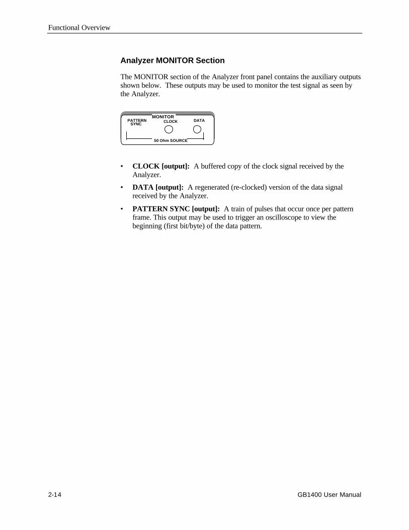
Analyzer MONITOR Section
The MONITOR section of the Analyzer front panel contains the auxiliary outputsshown below. These outputs may be used to monitor the test signal as seen bythe Analyzer.
• CLOCK [output]: A buffered copy of the clock signal received by theAnalyzer.
• DATA [output]: A regenerated (re-clocked) version of the data signalreceived by the Analyzer.
• PATTERN SYNC [output]: A train of pulses that occur once per patternframe. This output may be used to trigger an oscilloscope to view thebeginning (first bit/byte) of the data pattern.
PATTERNSYNC
CLOCK DATAMONITOR
50 Ohm SOURCE
Functional Overview
GB1400 User Manual 2-15
Analyzer Rear Panel
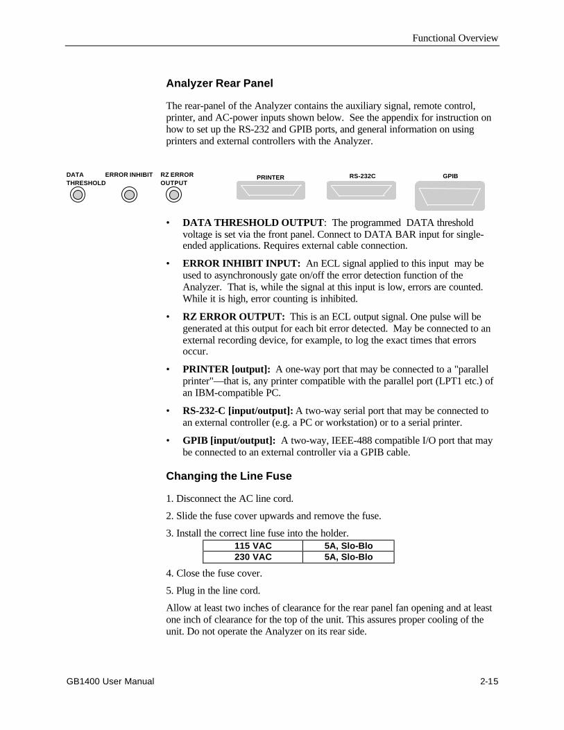
The rear-panel of the Analyzer contains the auxiliary signal, remote control,printer, and AC-power inputs shown below. See the appendix for instruction onhow to set up the RS-232 and GPIB ports, and general information on usingprinters and external controllers with the Analyzer.
PRINTERDATATHRESHOLD
ERROR INHIBIT RZ ERROROUTPUT
RS-232C GPIB
• DATA THRESHOLD OUTPUT: The programmed DATA thresholdvoltage is set via the front panel. Connect to DATA BAR input for single-ended applications. Requires external cable connection.
• ERROR INHIBIT INPUT: An ECL signal applied to this input may beused to asynchronously gate on/off the error detection function of theAnalyzer. That is, while the signal at this input is low, errors are counted.While it is high, error counting is inhibited.
• RZ ERROR OUTPUT: This is an ECL output signal. One pulse will begenerated at this output for each bit error detected. May be connected to anexternal recording device, for example, to log the exact times that errorsoccur.
• PRINTER [output]: A one-way port that may be connected to a "parallelprinter"—that is, any printer compatible with the parallel port (LPT1 etc.) ofan IBM-compatible PC.
• RS-232-C [input/output]: A two-way serial port that may be connected toan external controller (e.g. a PC or workstation) or to a serial printer.
• GPIB [input/output]: A two-way, IEEE-488 compatible I/O port that maybe connected to an external controller via a GPIB cable.
Changing the Line Fuse
1. Disconnect the AC line cord.
2. Slide the fuse cover upwards and remove the fuse.
3. Install the correct line fuse into the holder.115 VAC 5A, Slo-Blo230 VAC 5A, Slo-Blo
4. Close the fuse cover.
5. Plug in the line cord.
Allow at least two inches of clearance for the rear panel fan opening and at leastone inch of clearance for the top of the unit. This assures proper cooling of theunit. Do not operate the Analyzer on its rear side.

Functional Overview
2-16 GB1400 User Manual
Connectors, Terminations, and Levels
Tables 2-1 and 2-2 below summarize the physical interface characteristics of allGB1400 Generator and Analyzer inputs and outputs.
Table 2-1. Generator (Tx) Inputs and Outputs
Connector Label Signal Type Location ConnectorType
Impedance, amplitude,and offset
DATA output OUTPUT section SMA,female
50 Ohm, see NOTE 1,variable amplitude andoffset
CLOCK output OUTPUT section SMA,female
50 Ohm, see NOTE 1,variable amplitude andoffset
DATA-BAR output OUTPUT section SMA,female
50 Ohm, see NOTE 1,variable amplitude andoffset
CLOCK-BAR output OUTPUT section SMA,female
50 Ohm, see NOTE 1,variable amplitude andoffset
CLOCK/4 output OUTPUT section SMA,female
50 Ohm, 200mV into 50Ω
PATTERN SYNC output OUTPUT section SMA,female
50 Ohm, 200mV into 50Ω
CLOCK INPUT input CLOCK section SMA,female
50 Ohm, 2V max, seeNOTE 2
DATA INHIBIT input rear panel BNC,female
50 Ohm to -2V, ECL
ERROR INJECT input rear panel BNC,female
50 Ohm to -2V, ECL
RS-232 I/O rear panel 25 pin, Dtype
RS-232C standard levelsand impedance
GPIB I/O rear panel GPIB IEEE-488 standard levelsand impedance
Note 1: A 75-Ohm version of the GB1400 is an option.Note2: BURST Mode units require ECL-level inputs and are terminated with 50-Ohms to -2V.
Functional Overview
GB1400 User Manual 2-17
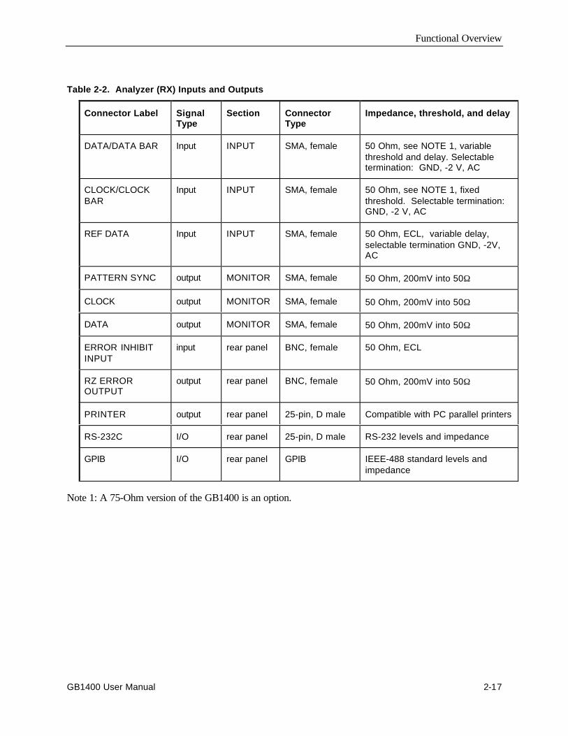
Table 2-2. Analyzer (RX) Inputs and Outputs
Connector Label SignalType
Section ConnectorType
Impedance, threshold, and delay
DATA/DATA BAR Input INPUT SMA, female 50 Ohm, see NOTE 1, variablethreshold and delay. Selectabletermination: GND, -2 V, AC
CLOCK/CLOCKBAR
Input INPUT SMA, female 50 Ohm, see NOTE 1, fixedthreshold. Selectable termination:GND, -2 V, AC
REF DATA Input INPUT SMA, female 50 Ohm, ECL, variable delay,selectable termination GND, -2V,AC
PATTERN SYNC output MONITOR SMA, female 50 Ohm, 200mV into 50Ω
CLOCK output MONITOR SMA, female 50 Ohm, 200mV into 50Ω
DATA output MONITOR SMA, female 50 Ohm, 200mV into 50Ω
ERROR INHIBITINPUT
input rear panel BNC, female 50 Ohm, ECL
RZ ERROROUTPUT
output rear panel BNC, female 50 Ohm, 200mV into 50Ω
PRINTER output rear panel 25-pin, D male Compatible with PC parallel printers
RS-232C I/O rear panel 25-pin, D male RS-232 levels and impedance
GPIB I/O rear panel GPIB IEEE-488 standard levels andimpedance
Note 1: A 75-Ohm version of the GB1400 is an option.
Functional Overview
2-18 GB1400 User Manual
Controls and IndicatorsAll of the controls, indicators, inputs, and outputs found on the Generator orAnalyzer front or rear panels are discussed in the following section.
Power Switches
The ON/OFF power switch is located on the left side of the test instrument belowthe LCD screen. The power switch switches the 120/240 VAC to the systempower supply. When off, a Battery backup circuit powers the non-volatile RAM.
Unit Mounting
The GB1400 is designed to be placed: (1) flat on a level surface, capable ofsupporting its weight, or (2) angled from the surface with the rotating carryinghandle. To change the handle's orientation, press both handle-locking buttons(located at the hubs of the handle), rotate the handle to the desired angle, andrelease the buttons. The handle will click into a locked position. Assure that thehandle is locked before placing the unit on a work surface. A Rack mountingoption is available for installation of the unit into a 19" rackmount. The rackheight for the GB1400 is 7 inches (four RMU).
Unit Cooling
The rear panel fan openings must be kept clear for proper cooling of the unit.Allow a minimum of two (2) inches of rear panel clearance, and one (1) inch oftop clearance, while operating the unit.
View Angle and Panel Lock Keys
The PANEL LOCK and VIEW ANGLE keys are located near the top, left side ofthe front panel.
• VIEW ANGLE: Use this key to select the optimum LCD viewing angle.
• PANEL LOCK: Use this key to "lock" and "unlock" the front panel. Whilethe front panel is locked, all keys that can cause setup changes are disabled.This feature can help prevent accidental loss of data when performing long-term or critical tests.
RESET to Factory Default
To return the Generator or Analyzer to factory default settings, turn theinstrument OFF and then re-power it while pressing and holding the VIEWANGLE, MSB 1, and (PATTERN) CLEAR keys at the same time. Release thesekeys after the message Default Setup appears in the display.
Functional Overview
GB1400 User Manual 2-19
GPIB Section Controls
There are two keys in the GPIB section:
• ADDR: Key used to set GPIB address in the range 0 to 30.
• LOCAL: The LED in this key indicates whether the instrument is in thelocal mode (LED off) or remote mode (LED on). If the LED is on, you canreturn the instrument to local mode by pressing the LOCAL key.
Note that these two keys are used only when operating the instrument via itsGPIB port. For more information on the GPIB port and remote control in general,see the appendix. For detailed descriptions of all remote commands, see theappendix.
Functional Overview
2-20 GB1400 User Manual
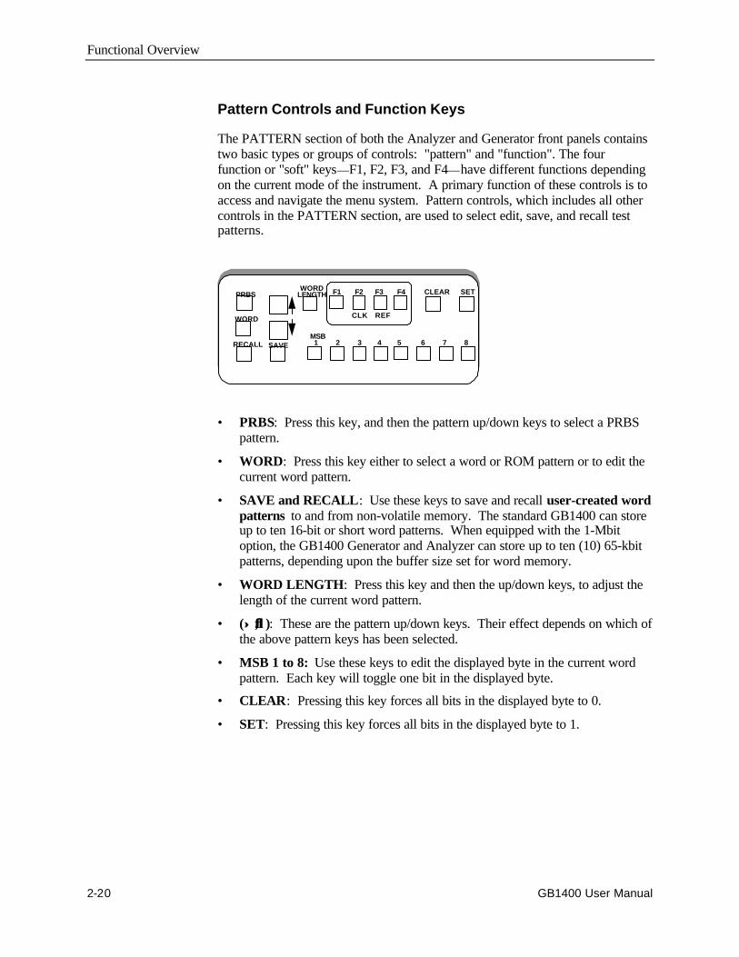
Pattern Controls and Function Keys
The PATTERN section of both the Analyzer and Generator front panels containstwo basic types or groups of controls: "pattern" and "function". The fourfunction or "soft" keys—F1, F2, F3, and F4—have different functions dependingon the current mode of the instrument. A primary function of these controls is toaccess and navigate the menu system. Pattern controls, which includes all othercontrols in the PATTERN section, are used to select edit, save, and recall testpatterns.
PRBS
WORD
RECALL SAVE
F1 F2 F3 F4
MSB 1 2 3 4 5 6 7 8
CLEAR SETWORDLENGTH
CLK REF
• PRBS: Press this key, and then the pattern up/down keys to select a PRBSpattern.
• WORD: Press this key either to select a word or ROM pattern or to edit thecurrent word pattern.
• SAVE and RECALL: Use these keys to save and recall user-created wordpatterns to and from non-volatile memory. The standard GB1400 can storeup to ten 16-bit or short word patterns. When equipped with the 1-Mbitoption, the GB1400 Generator and Analyzer can store up to ten (10) 65-kbitpatterns, depending upon the buffer size set for word memory.
• WORD LENGTH: Press this key and then the up/down keys, to adjust thelength of the current word pattern.
• (↑↑ ,↓↓ ): These are the pattern up/down keys. Their effect depends on which ofthe above pattern keys has been selected.
• MSB 1 to 8: Use these keys to edit the displayed byte in the current wordpattern. Each key will toggle one bit in the displayed byte.
• CLEAR: Pressing this key forces all bits in the displayed byte to 0.
• SET: Pressing this key forces all bits in the displayed byte to 1.
Functional Overview
GB1400 User Manual 2-21
Function (Soft) Keys (F1, F2, F3, and F4)
Menu Functions: The primary use of the function keys in the Generator andAnalyzer is to access and navigate each instrument's menu system. F1 may bethought of as the main menu key. Pressing F1 will display the instrument's firstlevel menu. Once inside the menu system, you may use the F1, F2, F3, and F4keys to select different menus, or to make choices within a selected menu. Notethat pressing the F1 key enough times will always get you out of the system. SeeChapter 3 - Reference for an explanation of each Generator and Analyzer menu.
Analyzer Inputs
These function keys provide signal inputs and control of parameters (InputTermination, Threshold, Logic Polarity and Data/Clock Phase Delay) for DATA,Ref DATA, and CLOCK.
Selecting DELAY, V-TERM or V-THRS permits the INPUT Up/Down keys tovary the Input parameters for DATA, as described below. Holding the Up/Downkey repeats the function five times a second.
Function key F2 (CLOCK) permits the V-TERM key to vary only the Inputtermination parameters for CLOCK.
Function key F3 (Ref DATA) permits the DELAY, V-THRS, and V-TERM keysto vary the Input parameters for Reference DATA.
DELAY - Pressing DELAY selects Input Data Delay adjust mode. The InputData signal can be delayed over the range 0.0 nS to 3.9 nS in sub-nanosecondsteps. The delay is modified with the INPUT Up/Down keys. The current Delayis displayed on the lower left side of the LCD.
An illuminated Delay LED light indicates that the unit's DELAY can be modifiedby the Up/Down arrow keys.
V-TERM - Pressing V-TERM selects V-termination mode. The inputtermination voltage for Input Data is selectable between GND, -2.0V, and AC.-2.0V mode provides active termination for ECL and GaAs signals. AC modeallows RF termination.
An illuminated V-TERM LED light indicates that the input termination can bemodified by the Up/Down arrow keys.
V-THRS - Pressing V-THRS selects V-Threshold mode. The Input Datathreshold is variable over the range of -1.5V to +1V in 50 mV steps. Thecurrently selected threshold voltage is displayed in the lower right side of theLCD display.
An illuminated V-THRS LED light indicates that the threshold voltage can bemodified by the Up/Down arrow keys.
The Data threshold voltage is available at the Analyzer rear panel SMA jacklabeled DATA THRESHOLD.
Print Setup Function (Analyzer only): You can print a report showing thecurrent setup of the Analyzer by pressing the F4 key. This function, however, isnot active in the menu mode.
Functional Overview
2-22 GB1400 User Manual
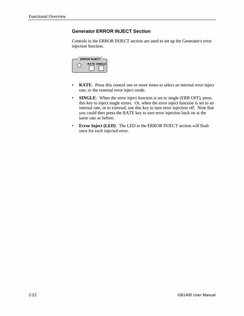
Generator ERROR INJECT Section
Controls in the ERROR INJECT section are used to set up the Generator's errorinjection function.
• RATE: Press this control one or more times to select an internal error injectrate, or the external error inject mode.
• SINGLE: When the error inject function is set to single (ERR OFF), pressthis key to inject single errors. Or, when the error inject function is set to aninternal rate, or to external, use this key to turn error injection off. Note thatyou could then press the RATE key to turn error injection back on at thesame rate as before.
• Error Inject (LED): The LED in the ERROR INJECT section will flashonce for each injected error.
RATE SINGLE
ERROR INJECT
Functional Overview
GB1400 User Manual 2-23
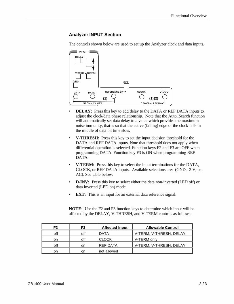
Analyzer INPUT Section
The controls shown below are used to set up the Analyzer clock and data inputs.
DELAY
V-TERM V-THRESH
D-INV
DATA DATA
EXT
50 Ohm, 2V MAX
(1)
REFERENCE DATA CLOCK CLOCK
50 Ohm, 1.5V MAX
(2)(1)
INPUT
• DELAY: Press this key to add delay to the DATA or REF DATA inputs toadjust the clock/data phase relationship. Note that the Auto_Search functionwill automatically set data delay to a value which provides the maximumnoise immunity, that is so that the active (falling) edge of the clock falls inthe middle of data bit time slots.
• V-THRESH: Press this key to set the input decision threshold for theDATA and REF DATA inputs. Note that threshold does not apply whendifferential operation is selected. Function keys F2 and F3 are OFF whenprogramming DATA. Function key F3 is ON when programming REFDATA.
• V-TERM: Press this key to select the input terminations for the DATA,CLOCK, or REF DATA inputs. Available selections are: (GND, -2 V, orAC). See table below.
• D-INV: Press this key to select either the data non-inverted (LED off) ordata inverted (LED on) mode.
• EXT: This is an input for an external data reference signal.
NOTE: Use the F2 and F3 function keys to determine which input will beaffected by the DELAY, V-THRESH, and V-TERM controls as follows:
F2 F3 Affected Input Allowable Control
off off DATA V-TERM, V-THRESH, DELAYon off CLOCK V-TERM only
off on REF DATA V-TERM, V-THRESH, DELAYon on not allowed
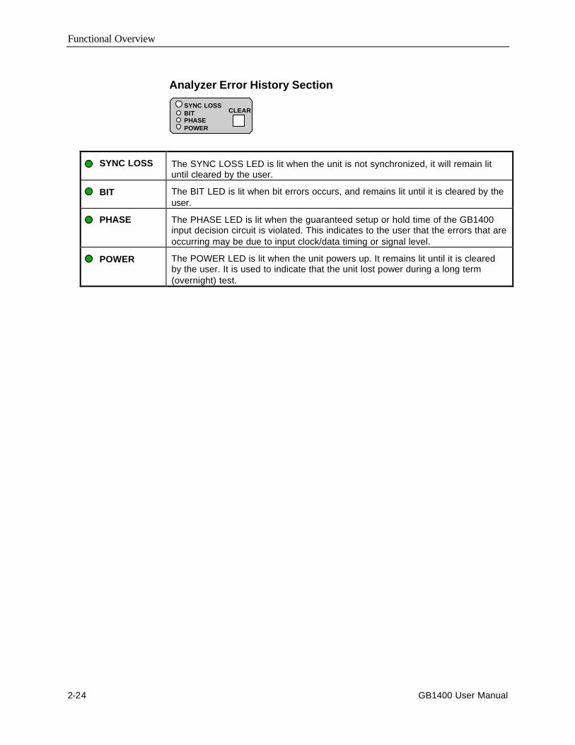
Functional Overview
2-24 GB1400 User Manual
Analyzer Error History Section
SYNC LOSS The SYNC LOSS LED is lit when the unit is not synchronized, it will remain lituntil cleared by the user.
BIT The BIT LED is lit when bit errors occurs, and remains lit until it is cleared by theuser.
PHASE The PHASE LED is lit when the guaranteed setup or hold time of the GB1400input decision circuit is violated. This indicates to the user that the errors that areoccurring may be due to input clock/data timing or signal level.
POWER The POWER LED is lit when the unit powers up. It remains lit until it is clearedby the user. It is used to indicate that the unit lost power during a long term(overnight) test.
CLEARSYNC LOSSBITPHASEPOWER
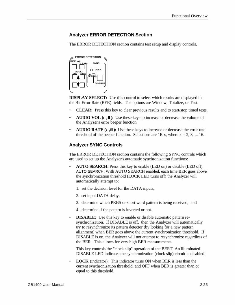
Functional Overview
GB1400 User Manual 2-25
Analyzer ERROR DETECTION Section
The ERROR DETECTION section contains test setup and display controls.
DISPLAY SELECT: Use this control to select which results are displayed inthe Bit Error Rate (BER) fields. The options are Window, Totalize, or Test.
• CLEAR: Press this key to clear previous results and to start/stop timed tests.
• AUDIO VOL (↑↑ , ↓↓ ): Use these keys to increase or decrease the volume ofthe Analyzer's error beeper function.
• AUDIO RATE (↑↑ , ↓↓ ): Use these keys to increase or decrease the error ratethreshold of the beeper function. Selections are 1E-x, where x = 2, 3, ... 16.
Analyzer SYNC Controls
The ERROR DETECTION section contains the following SYNC controls whichare used to set up the Analyzer's automatic synchronization functions:
• AUTO SEARCH: Press this key to enable (LED on) or disable (LED off)AUTO SEARCH. With AUTO SEARCH enabled, each time BER goes abovethe synchronization threshold (LOCK LED turns off) the Analyzer willautomatically attempt to:
1. set the decision level for the DATA inputs,
2. set input DATA delay,
3. determine which PRBS or short word pattern is being received, and
4. determine if the pattern is inverted or not.
• DISABLE: Use this key to enable or disable automatic pattern re-synchronization. If DISABLE is off, then the Analyzer will automaticallytry to resynchronize its pattern detector (by looking for a new patternalignment) when BER goes above the current synchronization threshold. IfDISABLE is on, the Analyzer will not attempt to resynchronize regardless ofthe BER. This allows for very high BER measurements.
This key controls the "clock slip" operation of the BERT. An illuminatedDISABLE LED indicates the synchronization (clock slip) circuit is disabled.
• LOCK (indicator): This indicator turns ON when BER is less than thecurrent synchronization threshold, and OFF when BER is greater than orequal to this threshold.
ERROR DETECTION
DISPLAYCLEAR
LOCK
DISABLE
VOL RATEAUDIO
AUTOSEARCH
SYNC
Functional Overview
2-26 GB1400 User Manual
Burst Mode Option
The standard GB1400 operates over a clock frequency range of 1 Mbit/s to 1400Mbit/s. The GB1400 Tx has an internal clock source that has a range of 1 MHz to1400 MHz. It also has a provision for using an external clock source of the samefrequency range. When using the external clock source, it must be appliedcontinuously without interruption. The GB1400 RX also requires that, at alltimes during the test, a clock signal within the 1 Mbit/s to 1400 Mbit/s frequencyrange be continuously applied. If the external clock signal should be removed , orgo below 1 MHz for any reason during the test, the RX will register OUT OFSYNC as soon as the clock signal is reapplied. This condition will initiate aresynchronization of the receiver and restart any tests.
For the Burst Mode option, the GB1400 RX has been modified to work normallyor in Burst Mode from 150 kHz to the normal 1400 MHz upper limit. The RXCLOCK and CLOCK BAR inputs have been modified for DC operation. Thismodification requires the removal of any blocking capacitors in the input path.The removal of the capacitors limits the allowable input signal to ECL levelsonly. Levels other than ECL may damage the input circuitry. The three standardclock input termination selections of GND, AC, and -2V are still present.
Note: The Clock may be used either differentially or single-ended. To use asingle-ended clock input, connect the ECL clock input to the CLOCK inputconnector. Select the -2V input termination, and connect DC bias voltage of -1.3VDC to the CLOCK BAR input connector.
These and other changes will now allow the receiver to maintain synchronizationwhenever CLOCK and DATA are synchronously stopped and started during atest pattern, providing there has not been a bit slip between CLOCK and DATA.
In both the Tx and RX, there can be any length of time that both CLOCK andDATA are off, and the minimum CLOCK/DATA applied can be as low as asingle cycle, providing the minimum of 714 pS and maximum of 667 µs clockperiod restrictions are observed.
Similar Tx circuit changes allow the Tx DATA and CLOCK outputs to follow,cycle by cycle, the input from a bursted External Clock Input. This means thatthe Tx can be used in a start-stop, or "Burst Mode".
For every clock cycle into the External Clock Input, there will be the samenumber of clock cycles and data bits output through the clock and data outputs.The time between clock cycle inputs is unrestricted and can be any length oftime. The number of clock cycles can be any number from continuous to a singlecycle. During the time there is no clock input to the External Clock Input, theinternal code generator is idle (not running). Each clock cycle steps the codegenerator by one bit. Clock cycle period must not be more than 667 µs (150kHz) nor less than 714 pS (1400 MHz).
Functional Overview
GB1400 User Manual 2-27
Burst Mode Usage
The Burst Mode option of the GB1400 will find usage in applications wheretraditional BERTs cannot operate. Traditional BERTs require a continuousCLOCK and DATA signal with no interruption. Should interruptions occur, theRX will resynchronize or indicate errors that actually did not occur due to theasynchronous re-start. The BURST MODE allows operation with a non-continuous clock.
There are communications and telemetry systems that do not necessarily senddata continuously. These systems send data in "bursts" with variable times ofinactivity between bursts. Traditional BERTs cannot accurately check thesesystems, especially if the bursts are of short duration. A traditional BERT mayrequire more bits than are available in the burst to (re)synchronize. Even if thebursts are large, many bits in the burst would not be checked during the(re)synchronization procedure.
In Burst Mode, the GB1400 RX will follow the input CLOCK and DATAwithout regard for inactive time between bursts. The only requirement is thatthere be no bit slips between the CLOCK and DATA at the Tx or UUT and therebe a clock cycle for every DATA bit received.
See figures on the next page for Transmit and Receive Operation with BurstMode.
Specifications for Burst Mode
• Maximum time between bursts - no restriction
• Minimum time between bursts - one clock period
• RX Clock Input - ECL level only; User-selectable termination 50 Ohms to-2V should be used. Minimum rate during burst - 150 kbit/s; Maximum rateduring burst - 1400 Mbit/s
• RX Auto Search restriction - Below 500 kbit/s, the Auto Search function cantake a very long time due to code word search. Finding both Threshold andDelay is rapid, but Data Pattern search is lengthy. Because of this, the usershould use Manual Search Mode to keep synchronization time as low aspossible.
• Restriction on other options - None
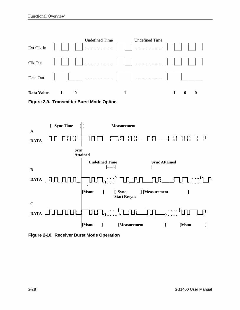
Functional Overview
2-28 GB1400 User Manual
Undefined Time Undefined Time
Ext Clk In ……………….. ………………..
Clk Out ……………….. ………………..
Data Out ……………….. ………………..
Data Value 1 0 1 1 0 0
Figure 2-9. Transmitter Burst Mode Option
A
DATA
B
DATA
C
DATA
[ Sync Time ] [ Measurement
Undefined Time Sync Attained |------| |
[Msmt ] [Measurement ] [Msmt ]
[Msmt ] [ Sync ] [Measurement ] Start Resync
SyncAttained
Figure 2-10. Receiver Burst Mode Operation
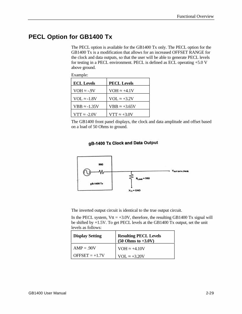
Functional Overview
GB1400 User Manual 2-29
PECL Option for GB1400 Tx
The PECL option is available for the GB1400 Tx only. The PECL option for theGB1400 Tx is a modification that allows for an increased OFFSET RANGE forthe clock and data outputs, so that the user will be able to generate PECL levelsfor testing in a PECL environment. PECL is defined as ECL operating +5.0 Vabove ground.
Example:
ECL Levels PECL Levels
VOH ≈ -.9V VOH ≈ +4.1V
VOL ≈ -1.8V VOL ≈ +3.2V
VBB ≈ -1.35V VBB ≈ +3.65V
VTT ≈ -2.0V VTT ≈ +3.0V
The GB1400 front panel displays, the clock and data amplitude and offset basedon a load of 50 Ohms to ground.
The inverted output circuit is identical to the true output circuit.
In the PECL system, Vtt = +3.0V, therefore, the resulting GB1400 Tx signal willbe shifted by +1.5V. To get PECL levels at the GB1400 Tx output, set the unitlevels as follows:
Display Setting Resulting PECL Levels(50 Ohms to +3.0V)
AMP = .90V
OFFSET = +1.7V
VOH ≈ +4.10V
VOL ≈ +3.20V
GB1400 User Manual 2-30
Tutorial
Basic BERT testing with the GB1400
A critical element in digital transmission systems is how error-free itstransmissions are. This measurement is made by a bit-error-rate tester (BERT).The GB1400 Generator (Tx) and Analyzer (Rx) are designed to operate at bitrates up to 1400 Mb/s. These portable instruments provide PRBS or UserDefined Patterns (up to 1Mbit deep) for high speed BERT testing.
Objective of Tutorial
Understand GB1400 instrument setup for BER testing using PRBS patterns.
Procedure
This tutorial programs the GB1400 Generator to provide PRBS clock and datasignals for the Analyzer. Using AUTO-SEARCH features, the Analyzer willsynchronize to the incoming PRBS test pattern. Bit Error Rate (BER)measurements will be performed on both good (error-free) and bad (user injectedfaults) data streams.
Key Feature of Tutorial
This lab demonstrates the use of AUTO-SEARCH Synchronization.
Equipment Required
Description Qty Part Number Source
GB1400 Generator 1 GB1400 Tx Tek
GB1400 Analyzer 1 GB1400 Rx Tek
50Ω Coax SMA cables, 1 meterlength, male to male
3 174-1341-00 Tek
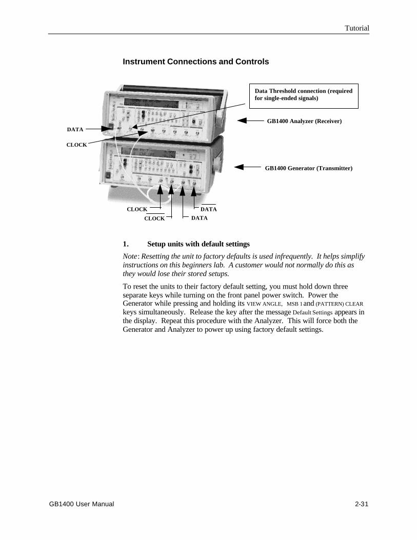
Tutorial
GB1400 User Manual 2-31
Instrument Connections and Controls
GB1400 Analyzer (Receiver)
GB1400 Generator (Transmitter)
CLOCK
CLOCK
DATA
DATA
DATA
CLOCK
Data Threshold connection (requiredfor single-ended signals)
1. Setup units with default settings
Note: Resetting the unit to factory defaults is used infrequently. It helps simplifyinstructions on this beginners lab. A customer would not normally do this asthey would lose their stored setups.
To reset the units to their factory default setting, you must hold down threeseparate keys while turning on the front panel power switch. Power theGenerator while pressing and holding its VIEW ANGLE, MSB 1 and (PATTERN) CLEAR
keys simultaneously. Release the key after the message Default Settings appears inthe display. Repeat this procedure with the Analyzer. This will force both theGenerator and Analyzer to power up using factory default settings.

Tutorial
2-32 GB1400 User Manual
2. Connect the Generator to the Analyzer.
Connect the generator and analyzer as shown below. The generator CLOCK outputconnects to the analyzer CLOCK input. The generator DATA output connects to theanalyzer DATA input. The rear panel THRESHOLD output on the Rx connects to theReceiver NOT-DATA input on the front panel. Terminate the generator NOT_CLOCK
and NOT_DATA signals with the 50Ω terminators located on the front panel of thegenerator.
GB1400 TX GB1400 RX
clock
data
clk clk data data data data clk clk
rear panelthreshold output
Note: Do not mix up the clock, not_clock, data, and not_data signals or tutorialresults will be different.
3. Setup Generator for PRBS-23 Mode.
Locate the controls in the OUTPUT box of the Generator. Setup the Generatorclock and data outputs as follows:
Set this parameter …to this value …using this procedure.
DATA amplitude. 1 volts Press the DATA key. The LED within the switchshould be lit.
Press AMPLITUDE up/down keys until dataamplitude is set to 2.00V.
DATA baseline offset -0.5 volt Press BASELINE OFFSET up/down keys untildata baseline offset is set to -0.50V.
CLOCK amplitude 1 volts Press CLOCK. (the LED within switch should belit).
Press AMPLITUDE up/down keys until clockamplitude is set to 2.00V.
CLOCK baselineoffset
-0.5 volt Press BASELINE OFFSET up/down keys untilclock baseline OFFSET is set to -0.50V.
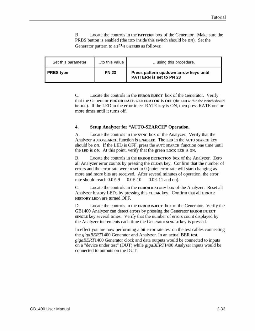
Tutorial
GB1400 User Manual 2-33
B. Locate the controls in the PATTERN box of the Generator. Make sure thePRBS button is enabled (the LED inside this switch should be ON). Set theGenerator pattern to a 223-1 bit PRBS as follows:
Set this parameter …to this value …using this procedure.
PRBS type PN 23 Press pattern up/down arrow keys untilPATTERN is set to PN 23
C. Locate the controls in the ERROR INJECT box of the Generator. Verifythat the Generator ERROR RATE GENERATOR is OFF (the LED within the switch shouldbe OFF). If the LED in the error inject RATE key is ON, then press RATE one ormore times until it turns off.
4. Setup Analyzer for “AUTO-SEARCH” Operation.
A. Locate the controls in the SYNC box of the Analyzer. Verify that theAnalyzer AUTO SEARCH function is ENABLED. The LED in the AUTO SEARCH keyshould be ON. If the LED is OFF, press the AUTO SEARCH function one time untilthe LED is ON. At this point, verify that the green LOCK LED is ON.
B. Locate the controls in the ERROR DETECTION box of the Analyzer. Zeroall Analyzer error counts by pressing the CLEAR key. Confirm that the number oferrors and the error rate were reset to 0 (note: error rate will start changing asmore and more bits are received. After several minutes of operation, the errorrate should reach 0.0E-9 ⇒ 0.0E-10 ⇒ 0.0E-11 and on).
C. Locate the controls in the ERROR HISTORY box of the Analyzer. Reset allAnalyzer history LEDs by pressing this CLEAR key. Confirm that all ERROR
HISTORY LED’s are turned OFF.
D. Locate the controls in the ERROR INJECT box of the Generator. Verify theGB1400 Analyzer can detect errors by pressing the Generator ERROR INJECT
SINGLE key several times. Verify that the number of errors count displayed bythe Analyzer increments each time the Generator SINGLE key is pressed.
In effect you are now performing a bit error rate test on the test cables connectingthe gigaBERT1400 Generator and Analyzer. In an actual BER test,gigaBERT1400 Generator clock and data outputs would be connected to inputson a "device under test" (DUT) while gigaBERT1400 Analyzer inputs would beconnected to outputs on the DUT.
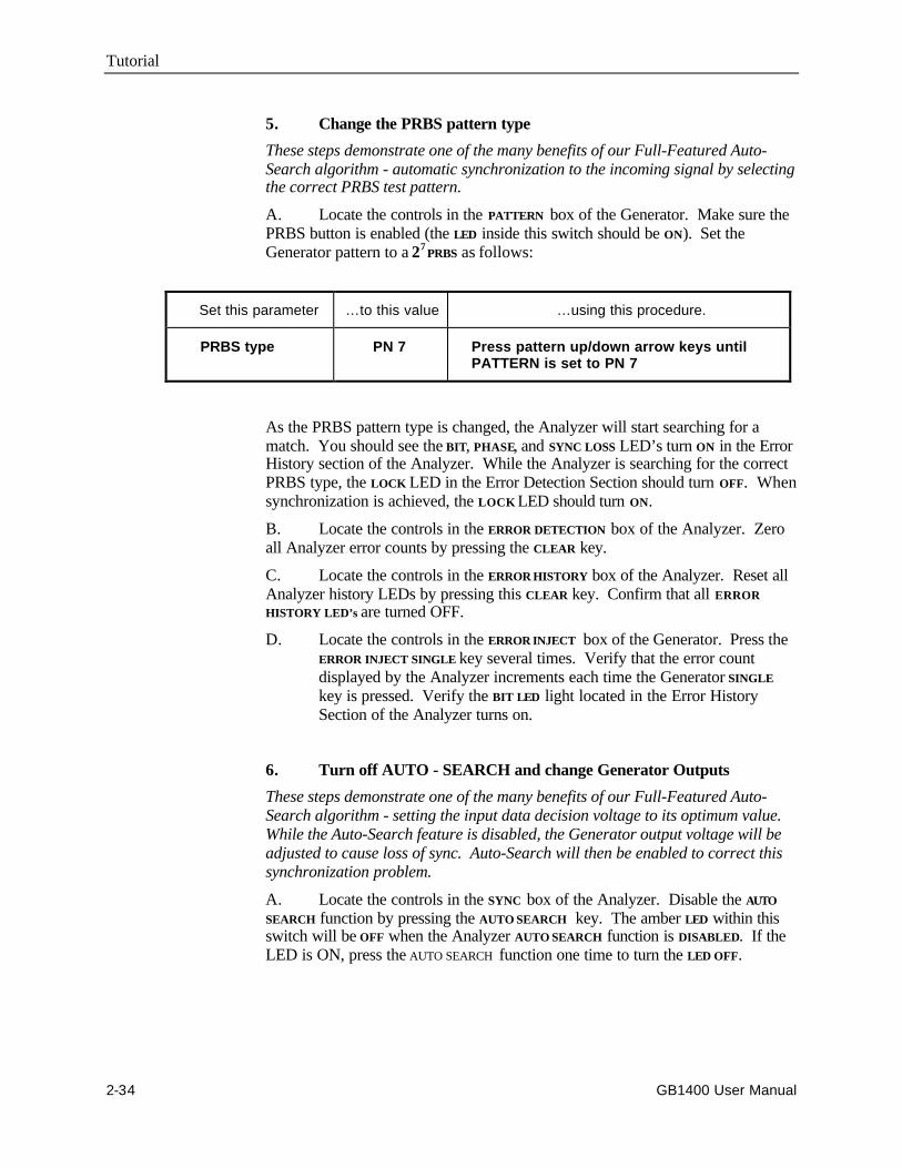
Tutorial
2-34 GB1400 User Manual
5. Change the PRBS pattern type
These steps demonstrate one of the many benefits of our Full-Featured Auto-Search algorithm - automatic synchronization to the incoming signal by selectingthe correct PRBS test pattern.
A. Locate the controls in the PATTERN box of the Generator. Make sure thePRBS button is enabled (the LED inside this switch should be ON). Set theGenerator pattern to a 27 PRBS as follows:
Set this parameter …to this value …using this procedure.
PRBS type PN 7 Press pattern up/down arrow keys untilPATTERN is set to PN 7
As the PRBS pattern type is changed, the Analyzer will start searching for amatch. You should see the BIT, PHASE, and SYNC LOSS LED’s turn ON in the ErrorHistory section of the Analyzer. While the Analyzer is searching for the correctPRBS type, the LOCK LED in the Error Detection Section should turn OFF. Whensynchronization is achieved, the LOCK LED should turn ON.
B. Locate the controls in the ERROR DETECTION box of the Analyzer. Zeroall Analyzer error counts by pressing the CLEAR key.
C. Locate the controls in the ERROR HISTORY box of the Analyzer. Reset allAnalyzer history LEDs by pressing this CLEAR key. Confirm that all ERROR
HISTORY LED’s are turned OFF.
D. Locate the controls in the ERROR INJECT box of the Generator. Press theERROR INJECT SINGLE key several times. Verify that the error countdisplayed by the Analyzer increments each time the Generator SINGLE
key is pressed. Verify the BIT LED light located in the Error HistorySection of the Analyzer turns on.
6. Turn off AUTO - SEARCH and change Generator Outputs
These steps demonstrate one of the many benefits of our Full-Featured Auto-Search algorithm - setting the input data decision voltage to its optimum value.While the Auto-Search feature is disabled, the Generator output voltage will beadjusted to cause loss of sync. Auto-Search will then be enabled to correct thissynchronization problem.
A. Locate the controls in the SYNC box of the Analyzer. Disable the AUTO
SEARCH function by pressing the AUTO SEARCH key. The amber LED within thisswitch will be OFF when the Analyzer AUTO SEARCH function is DISABLED. If theLED is ON, press the AUTO SEARCH function one time to turn the LED OFF.

Tutorial
GB1400 User Manual 2-35
B. Locate the controls in the OUTPUT box of the Generator. Adjust the Dataamplitude and offset as follows:
Caution: Adjust only the DATA signal. Do not change the CLOCK signal.
Set this parameter …to this value …using this procedure.
DATA amplitude. 0.50 volts Press the DATA key. The LED within the switchshould be lit.
Press AMPLITUDE up/down keys until dataamplitude is set to 0.50V.
DATA baseline offset -0.25 volts Press BASELINE OFFSET up/down keys untildata baseline offset is set to -0.25V.
If you examined this output data signal (voltage vs. time) on a scope, it wouldlook similar to:
+0.25 ←← Maximum Level
↑↑+0.00 0.5 V ←← Optimum Threshold
↑↑ amplitude
-0.25 ↓↓ ←← Minimum Level
Voltage ↑↑ -0.50 time →→
-0.25 Vdata offset
best value to use for THIS data
threshold is ~0.00 Vdc ++ 0.05 Vdc
You will now be manually adjusting the data input threshold for the GB1400Analyzer. Locate the controls in the PATTERN box of the Analyzer. Make sure
F2 and F3 are turned OFF. These switches are used when adjustingCLOCK or REF DATA input parameters.
C. Locate the controls in the INPUT box of the Analyzer. Verify that theAnalyzer THRESH LED is turned ON. This allows manual adjustment of the DATA
Input threshold. The threshold for the selected signal (clock or data) is shown onthe bottom line of the Analyzer’s alpha-numeric status display. Using the INPUT
UP/DOWN keys, adjust this threshold and confirm the following actions:
Note: The BER display on the Analyzer can be set to totalize, window, or testmodes. When in the totalize mode, a small ∞∞ (infinity) symbol will be displayedbefore the BER error rate. Use totalize mode for this tutorial exercise. Press theERROR DETECTION DISPLAY key several times to setup the analyzer for totalizemode..
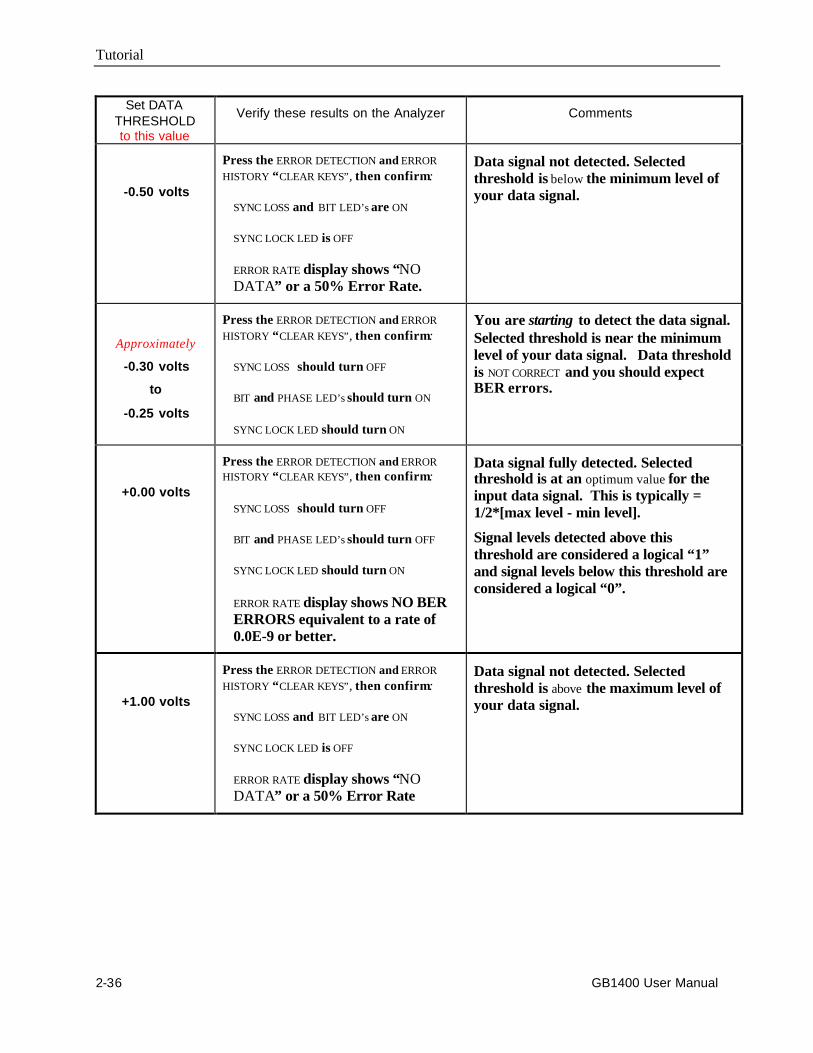
Tutorial
2-36 GB1400 User Manual
Set DATATHRESHOLDto this value
Verify these results on the Analyzer Comments
-0.50 volts
Press the ERROR DETECTION and ERROR
HISTORY “CLEAR KEYS”, then confirm:
SYNC LOSS and BIT LED’s are ON
SYNC LOCK LED is OFF
ERROR RATE display shows “NODATA” or a 50% Error Rate.
Data signal not detected. Selectedthreshold is below the minimum level ofyour data signal.
Approximately
-0.30 volts
to
-0.25 volts
Press the ERROR DETECTION and ERROR
HISTORY “CLEAR KEYS”, then confirm:
SYNC LOSS should turn OFF
BIT and PHASE LED’s should turn ON
SYNC LOCK LED should turn ON
You are starting to detect the data signal.Selected threshold is near the minimumlevel of your data signal. Data thresholdis NOT CORRECT and you should expectBER errors.
+0.00 volts
Press the ERROR DETECTION and ERRORHISTORY “CLEAR KEYS”, then confirm:
SYNC LOSS should turn OFF
BIT and PHASE LED’s should turn OFF
SYNC LOCK LED should turn ON
ERROR RATE display shows NO BERERRORS equivalent to a rate of0.0E-9 or better.
Data signal fully detected. Selectedthreshold is at an optimum value for theinput data signal. This is typically =1/2*[max level - min level].
Signal levels detected above thisthreshold are considered a logical “1”and signal levels below this threshold areconsidered a logical “0”.
+1.00 volts
Press the ERROR DETECTION and ERROR
HISTORY “CLEAR KEYS”, then confirm:
SYNC LOSS and BIT LED’s are ON
SYNC LOCK LED is OFF
ERROR RATE display shows “NODATA” or a 50% Error Rate
Data signal not detected. Selectedthreshold is above the maximum level ofyour data signal.
Tutorial
GB1400 User Manual 2-37
D. Locate the controls in the SYNC box of the Analyzer. Verify that theAUTO SEARCH function is ENABLED. The LED in the AUTO SEARCH key should be ON.If the LED is OFF, press the AUTO SEARCH function one time to turn the ON. Atthis point, verify that the green LOCK LED is ON.
The Analyzer will now search and calculate a new data threshold. What is thevalue of the threshold selected by Auto-Search? You should expect to see thisthreshold value within a few hundred millivolts of the “data signal mid-point (oroptimum threshold).
Note - Common Setup Problems
• Connecting the Generator’s clock output to the Analyzer’s not-clock (clock-bar) input
• Connecting the Generator’s data output to the Analyzer’s not-data (data-bar)input
• Changing Generator’s CLOCK amplitude/offset when lab calls foradjustments to DATA signals
• Failure to connect the external DATA THRESHOLD cable from rear of unitto NOT_DATA input.
This Concludes the Tutorial.
2-38 GB1400 User Manual
Applications
Application Note
Method For Very Fast Automatic Receiver SynchronizationAnd Eye Width Measurement
Two Auto Search Synchronization Methods
This application note describes two Auto Search synchronization methods usedin the GB1400 Bit Error Rate test set - a FAST method and a BER method. Thecriteria and sequence of events for the two methods are compared and thedifferences are described.
Auto Search is the feature that the GB1400 uses to describe its method ofautomatic setup and synchronization. Both methods of Auto Searchsynchronization perform the following functions, but in different ways and withdiffering results depending on the type of data and its quality.
• Analysis of the input data signal amplitude to select the correct thresholdvoltage.
• Determine the timing skew between the clock and data signals andautomatically optimize it.
• Determine the correct data sequence and whether it is inverted.
• Measure the data eye width.
So that the following explanations are clear, let us first define some terms.
V–THRESHOLD
This is the absolute DC level above which GB1400 Receiver will declare a databit value of “1” (HIGH). Below this value, it is considered to be a “0” (LOW).
DELAY
This is the timing difference (skew) between ideal timing and actual timingbetween the incoming clock and data. Ideal timing will place the falling edge ofthe clock signal in the center of the data bit. Any deviation from the ideal should,when possible, be corrected by delaying either the clock or the data (as in theGB1400 Receiver) in relation to each other.
Application Note - Auto Search Synchronization
GB1400 User Manual 2-39
PHASE
This is a unique and very fast method of determining where the edge of a data bitis in relation with the clock. The determination of phase errors is done bymonitoring the logic value of a data bit at the selected threshold voltage anddelay at two slightly different times. If the logic value is the same at the twodifferent times, then a phase error has not occurred. This method will work wellwith any data that is relatively noise, jitter and glitch free.
SYNCHRONIZATION
When we state that “the receiver is synchronized”, we mean that the GB1400Receiver’s internal reference data pattern generator is bit for bit properly alignedwith the incoming data from the device under test. When in synchronization, thereceiver can perform a bit for bit check of the incoming data against its internalreference to determine bit errors.
DATA POLARITY
This refers to whether the device under test has inverted the data logic in relationto what was input to it.
DATA EYE
This is a method of showing the data in a visual form. It is displayed on anoscilloscope using the clock as a trigger, and the data into the vertical amplifier.Case 1 of Diagram 1 of this application note is an example of data eye.
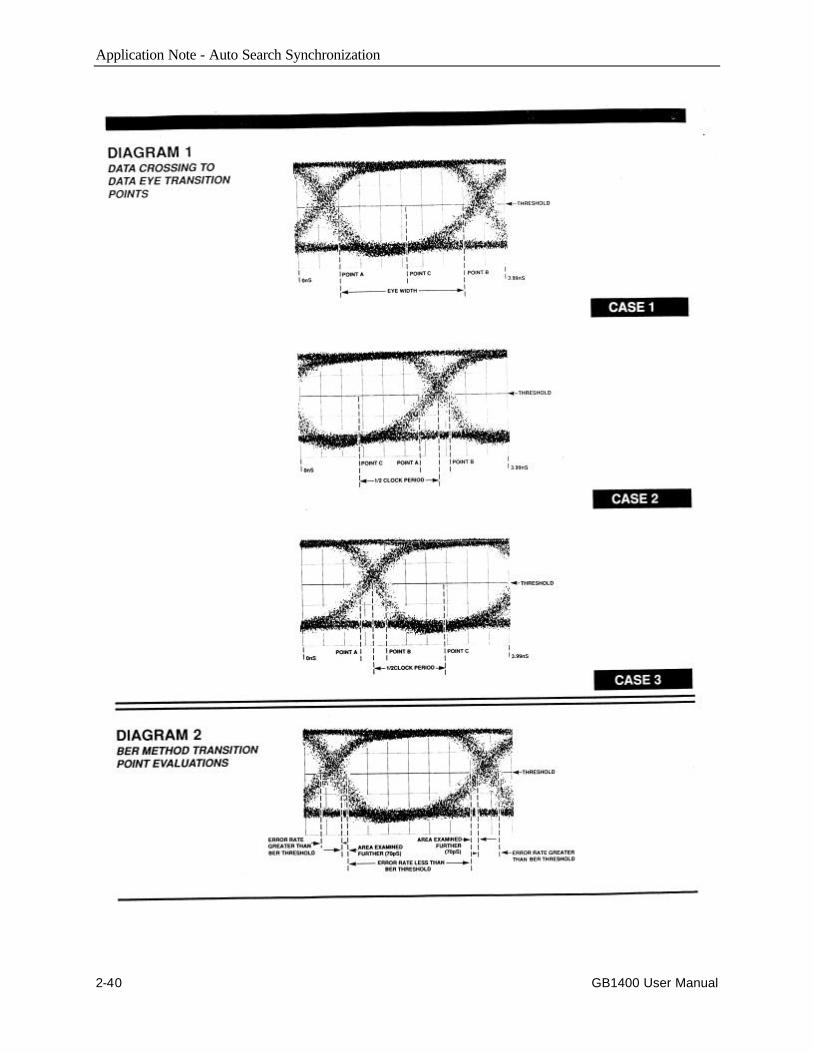
Application Note - Auto Search Synchronization
2-40 GB1400 User Manual
Application Note - Auto Search Synchronization
GB1400 User Manual 2-41
I. Auto Search Algorithm – “Fast” Method
Auto Search will determine the Data V- Threshold, Data Delay, Data Pattern andPolarity automatically. The so called “FAST” method has been given its namebecause of the speed with which it determines the threshold voltage setting,delay, data pattern and polarity. This is the default method used by the GB1400Receiver.
The speed is derived mainly from the use of the GB1400’s PHASE edgedetection circuitry which enables the receiver to quickly determine the transitionpoints of the eye without regard to the actual pattern, or even if the receiver isproperly linked up to the incoming data pattern.
If the data is not clean (glitches, excessive jitter or noise) this method willpossibly not work well. For these cases, use the “BER” method described later inthis document.
The “FAST” method of determining the proper settings for the V-Threshold,Delay, Pattern and Polarity is as follows:
Auto Search will find the DATA V-THRESHOLD voltage.
1. The receiver examines DATA ACTIVITY at each of the V-THRESHOLDsettings.
2. The receiver then locates and uses the middle of the largest voltage rangewhich has data activity. If no activity is detected, or if the range of activity isless than 250 mV, then the receiver indicates “NO DATA” has beendetected.
Auto Search will find the DATA DELAY.
1. For each delay setting, the receiver keeps track of the PHASE indication.
2. It then locates the largest contiguous block of delay settings without anyPHASE indication.
If BOTH ends of the clear block are within the 4 nS, delay range of thereceiver, it then sets the delay to the middle of the block. A measured eyewidth is available.
If BOTH ends of the clear block are the edges of the receiver delay range (nocrossing found), it then sets the delay to the middle of its delay range (1.995nS). No eye width is available.
If NO clear block is found (no crossing found); it then sets the delay to themiddle of its delay range (1.995nS). No eye width is available.
If ONE end of the clear block is on the edge and the width of the clear blockis less than half the data period, it then sets the delay to that edge (0 or3.99nS). No eye width available.
If ONE end of the clear block is on the edge and the width of the clear blockis greater than half the data period, it then sets the delay to be away from thefound crossing by half the clock period. A calculated eye width is available.
Application Note - Auto Search Synchronization
2-42 GB1400 User Manual
Auto Search will find the DATA PATTERN and POLARITY.
1. The receiver then attempts to SYNC on each data pattern and Polarity (10possibilities). If sync is found, STOP.
2. Attempt the previous step ten times. If the pattern is not found after tentimes, go back to "Find Data V-Threshold".
II. AUTO SEARCH Algorithm – BER Method
Like the “FAST” method of Auto Search, the “BER” method will also determinethe V-Threshold, data delay, data pattern and polarity. For this method to work,the receiver is sensitive to the data it is analyzing and must be synchronized withthe incoming data.
This method requires the user to set criteria pertaining to Bit Error Rate thresholdand sample size that is used to determine the size and center of the data eye.Because of the adjustability of the threshold and sample size, this method can bemade less susceptible to noise and glitches. The methods involved in analyzingthe data are quite rigorous and can require considerably more time than the“FAST” method.
Since the GB1400 is capable of measuring and displaying "eye width", theSAMPLE and BER THRESHOLD criteria requirements in the BER method, ifselected intelligently, tend to yield more accuracy and repeatability and is lesssubject to glitches, noise, and jitter than the "FAST" method
The Auto Search BER method of determining the proper settings of the V-Threshold, Patter, Polarity and Delay is as follows:
Auto Search will find the DATA V–THRESHOLD voltage.
1. The receiver examines DATA ACTIVITY at each of the V – THRESHOLDsettings.
2. The receiver then locates and uses the middle of the largest voltage rangewhich has data activity. If no activity is detected, or if the range of activity isless than 250 mV, then the receiver indicates “NO DATA” has beendetected.
Auto Search will then attempt to find the DATA PATTERN.
This is because the data pattern needed to be able to do the BER measurements.
1. The receiver first sets the data delay to 0pS and attempts to SYNC on eachdata pattern and polarity (10 possibilities). If found, go to the sectionDetermine Data Delay below.
2. The receiver then sets the data delay to 1/2 of the clock period and attemptsto sync on patterns (see step 2a above). If it is found, then go to the sectionDetermine Data Delay below. (If the frequency is less than 250 MHz, thereceiver will use 4nS instead of the incoming clock period throughout FindData Pattern)
Application Note - Auto Search Synchronization
GB1400 User Manual 2-43
3. If unsuccessful, it will then try the following data delays in the previous step-1/4 per, 3/4 per, 1/8 per, 5/8 per, 3/8 per, 7/8 per.
4. If sync is still not found, go back to the first section Find Data V-Threshold.
Auto Search will determine the Data Delay.
1. Initially the entire delay range (0nS to 3.99 nS) in steps of 70pS will besampled for 20mS each for error rate. The selectable BER Threshold will beused to determine if the delay settings are within the data eye crossings.
2. The largest contiguous block of delay measurements with error rates belowthe threshold will be found. Using that data, the transitions from datacrossing to data eye can be found.NOTE: This will be with 70 pS granularity.
If two transitions are within the receiver delay range, two points will be re-examined such that the data eye center and width can be determined. (Seeillustration /diagram #1, Case #1).
If BOTH ends of the clear block are the edges of the receiver delay range (noCrossing found), set the delay to the middle of the receiver delay range.STOP. No eye width is available.
If NO clear block is found (no crossing found), set the delay to the middle ofthe receiver delay range.STOP. No eye width is available.
If ONE end of the clear block is on the edge and the width of the clear blockis less than half the clock period, set the delay to that edge.STOP. No eye width is available.
If ONE end of the clear block is on the edge and the width of the clear blockis greater than half the clock period, two transition points, A and B, will bere-examined further (see Diagram 1, Cases 2 and 3).
3. If the transition points are to be evaluated further, an area 70pS wide will beexamined in steps of 5pS for 20ms each. This starts from the first delaysetting in the data crossing and goes to the first delay setting in the data eye(see Diagram 2).
4. After the areas have been measured for error rate, the areas will be examinedfor the first transition from below the threshold to above the threshold staringwith the end closest to the data eye center. These points will be the NEWtransition points.
5. Each of these NEW transition points will be re-examined for a length of timebased upon the SAMPLE size. The error rate will be compared with theselectable BER Threshold.
If the error rate is below the Threshold, the next point away from the DataEye Center will be examined, and so on, until the error rate transitions toabove the Threshold. The last point below the Threshold will be the TRUEtransition point.

Application Note - Auto Search Synchronization
2-44 GB1400 User Manual
If the error rate is above the Threshold, the next point toward the Data EyeCenter will be examined, and so on, until the error rate transitions to belowthe Threshold. The first point below the Threshold will be the TRUEtransition point.
6. After the new transition points are re-examined and the TRUE transitionpoints are found, the delay will be set as follows:
For Case 1, the delay will be set to the middle of the two TRU transitionpoints (point C).
For Cases 2 and 3, the delay will be set to be away from the middle of theTRUE transition points by half the data clock period (point C).
7. Eye Width Measurement
In the previous step above, if the error rate is below the threshold, themeasured eye width is the point B delay measurement minus the point Adelay measurement in Diagram 1, Case 1. STOP.
In the previous step above, if the error rate is above the threshold, thecalculated eye width for Diagram 1 Case 2 is the delay measurement at pointA minus the delay measurement at point C, times two. STOP.
In the previous step above, if the error rate is above the threshold, thecalculated eye width for Diagram 1, Case 3 is the delay measurement at pointC minus the delay measurement at point B, times two. STOP.

Application Note - Auto Search Synchronization
GB1400 User Manual 2-45
Consideration In Determining The Eye Data Width
In most circumstances a test signal data eye displayed on an oscilloscope willappear to be larger than that reported by the GB1400 Receiver. This is expectedand is due to several factors. One is that low error rates are virtually impossibleto see on an oscilloscope. Other factors such as set-up and hold time and signalcharacteristics will all have an effect on the measurement by decreasing theapparent eye size.
The value of an eye width measurement made on the GB1400 is when it is usedin a relative manner. If a device is determined to be working correctly using aknown good signal, its eye width can be measured on the GB1400 Receiver. Thatmeasurement can be used as stable reference standard against which all otherdevices can be measured. It is not possible for the GB1400 Receiver to duplicateall characteristics of the actual device that will be connected in its place, but itwill usually suffice as a reasonable approximation.
Consideration In Determining The Data Eye Center
In theory, a plot of bit error versus delay setting will show a smooth curve,almost linear, which has no aberrations and transitions from horizontal to almostvertical at the data eye crossing. For a signal with this curve (a clean signal withno aberrations, jitter or wander), the measurement of the data eye center will beconsistent using either of the methods.
In typical applications, the method which will assure a repeatable measurementof the data eye center is to measure each and every delay setting for a significantnumber of data bits. Because of probable aberrations in the data signals,measuring coarsely over the delay (using 70pS steps) MAY lead to inconsistentmeasurements due to the aberrations being seen during one search and not thenext.
Delay Specifications
The GB1400 programmable delay has the following nominal specifications:
Range: 0 – 3.99 Ns
Resolution: 5 pS
Accuracy: +/- 20 pS

2-46 GB1400 User Manual
Application Example
GB700/ GB1400 Optical Component Test
Clock Recoveryand
Retiming
Clock DataData
gB-Series RxgB-Series Tx
Fiber Optic Link Test Example
Fiber Optic
Clock
A typical BERT application is measuring the error performance of the electrical-to-optical (E/O) and optical-to-electrical (O/E) output modules of a fiber optictransmission system, as shown in the diagram above. Not all fiber optic links aredesigned for extremely high speed. For example, many data communicationsLANs use FDDI at 133 Mb/s. Serial digital video links operate at 270 Mb/s.
External Clock input shown on the BERT Tx would be used to provide jitteredclock to stress Clock Recovery (CR) circuit.
Longer PRBS patterns, such as 223 might be used to test DC wandersusceptibility of the CR subsystem.
Peak-to-peak amplitude and level offset of the BERT Tx output may be varied todetermine acceptable operating range for the DUT input circuitry.
Tests may be made using short and long fiber cables to be able to specifymaximum allowable length of fiber runs.
Note that in this application, it may be an advantage to be able to separate theBERT Tx and Rx. Using the BERT internal PRBS generator makes it easy toassure that the Tx and Rx have the same data for error comparison.

2-47 GB1400 User Manual
Application Example
Fibre Channel Link Testing Parallel and High-speed Serial
BUSInterface
BUSInterface
gigaBERT(Serial)
E / O
BUS - Serial Serial - BUS
Fiber
Interface Under Test
Tx
Rx
gigaBERT(Serial)
Tx
Tx
Rx
Rx
O / E
Parallel stimulus Parallel results
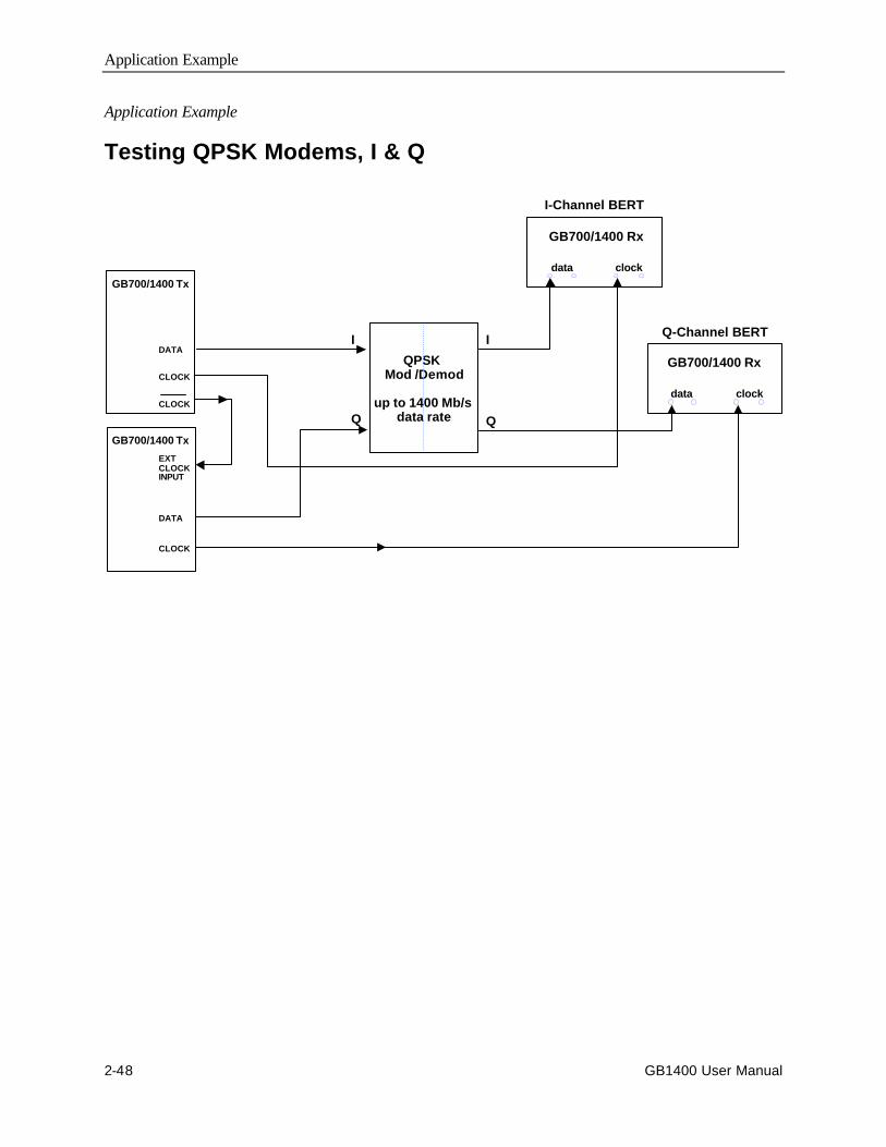
Application Example
2-48 GB1400 User Manual
Application Example
Testing QPSK Modems, I & Q
QPSK Mod /Demod
up to 1400 Mb/s data rate
I
Q
I
Q
GB700/1400 Tx
DATA
CLOCK
GB700/1400 Rx
data clock
GB700/1400 Rx
data clock
I-Channel BERT
Q-Channel BERT
GB700/1400 Tx
DATA
CLOCK
EXTCLOCKINPUT
CLOCK
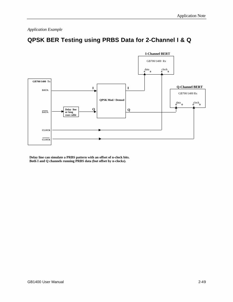
Application Note
GB1400 User Manual 2-49
Application Example
QPSK BER Testing using PRBS Data for 2-Channel I & Q
QPSK Mod / Demod
I
Q
I
QDelay line or long coax cable
GB700/1400 Tx
DATA
CLOCK
DATA
CLOCK
Delay line can simulate a PRBS pattern with an offset of n-clock bits. Both I and Q channels running PRBS data (but offset by n-clocks).
GB700/1400 Rx
data clock
GB700/1400 Rx
data clock
I-Channel BERT
Q-Channel BERT

Application Example
2-50 GB1400 User Manual

Reference

GB1400 User Manual 3-1
Reference
Menu Overview
A wide range of "auxiliary" setup functions is provided in the GB1400 Generatorand Analyzer Menu systems. To enter the Generator or Analyzer Menu system,simply press the instrument's F1 key. At this point the format of the display willchange to show the first page of the top level Menu. The top level Menu in boththe Generator and Analyzer contains other Menus and various setup parameters.Once inside the Menu system, you use the functions keys, F1 ... F4, to navigateto any Menu function, and to make selections within each Menu function.
Functions Common to Generator (TX) and Analyzer (RX)
AC Power
The GB1400 Generator and Analyzer are both AC powered. The power switch ofboth instruments is located on the front panel.
Selecting 115 VAC or 230 VAC Operation
Both the GB1400 Generator and Analyzer are equipped with an auto-ranging ACpower supply. This supply will operate over a voltage range of 90 to 250 VAC,and a frequency range of 47 to 63 Hz. Thus, no setup change is required tooperate from 115 VAC at 60 Hz or 230 VAC at 50 Hz.
Turning Instrument Power ON/OFF
The Generator and Analyzer are equipped with AC power switches on the frontpanel.
LCD Viewing Angle
The optimum viewing angle of the GB1400 Generator or Analyzer LCD displaymay be adjusted using the VIEW ANGLE control. Each press of the VIEWANGLE key will raise the optimum view angle until the highest angle is reached.The next press of VIEW ANGLE will return optimum viewing angle to its lowestangle, and so on.

Reference
3-2 GB1400 User Manual
Recalling the Default Setup
The default setup of the Generator and Analyzer are shown in the Appendix. Toreturn the Generator or Analyzer to this setup, use the following procedure:
1. Turn instrument power off.
2. While holding down the VIEW ANGLE, MSB 1, and (PATTERN) CLEARkeys simultaneously, turn instrument power back on.
3. After you see the message Default Settings appear in the display, release thethree keys. In a few seconds the normal display format will appear and theinstrument will be in its default setup.
Locking the Front Panel
The instrument's front panel may be "locked" or "unlocked" using the PANELLOCK control. When the front panel is locked, all keys that can cause a setupchange are disabled. It is often useful to lock the front panel during a long orcritical test to prevent accidental loss of test results. Note that the LED in thePANEL LOCK control indicates whether the front panel is locked (LED on) orunlocked (LED off).
Simply press the PANEL LOCK control to toggle between the locked (LED on)and unlocked (LED off) state.
Selecting a Pattern
The following section defines the patterns that can be generated and analyzed bythe GB1400 and how to set up the Generator and Analyzer to use a particularpattern. Note that the Generator and Analyzer are compatible with the same suiteof test patterns and use the same setup procedures.
Pattern Definitions
The GB1400 can generate and analyze Pseudo-random bit sequence (PRBS) andWORD test patterns. Each type has its own set of advantages and uses.
PRBS Patterns
Pseudo-random bit sequence (PRBS) patterns are designed to simulate "livetraffic" and have been standardized by the telecommunications and computerindustries. As a result they are often used to characterize or qualify new devicesor systems. Two key characteristics of a PRBS are its overall length in bits andmaximum number of contiguous 0s. The length of a PRBS pattern has the form2n-1. For example a 223-1 PRBS contains 8,388,607 bits. The maximum numberof contiguous 0s in a PRBS pattern is n-1, for example 22 in a 223-1 PRBS.
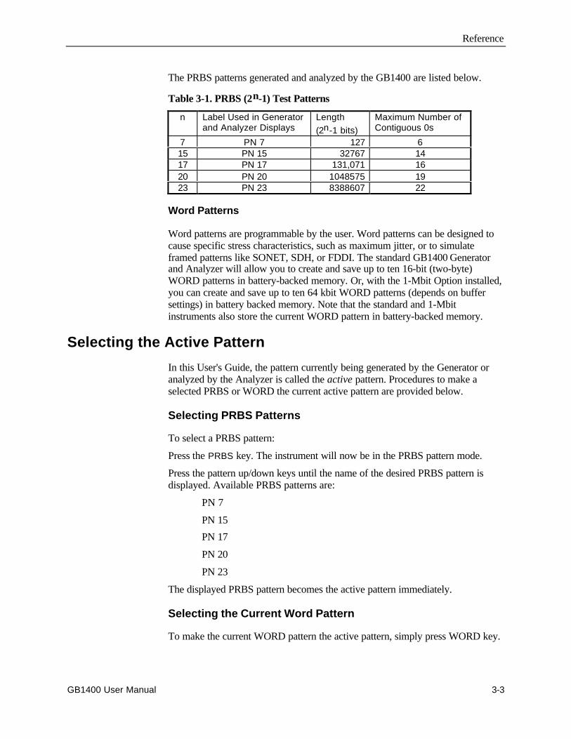
Reference
GB1400 User Manual 3-3
The PRBS patterns generated and analyzed by the GB1400 are listed below.
Table 3-1. PRBS (2n-1) Test Patterns
n Label Used in Generatorand Analyzer Displays
Length(2n-1 bits)
Maximum Number ofContiguous 0s
7 PN 7 127 615 PN 15 32767 1417 PN 17 131,071 1620 PN 20 1048575 1923 PN 23 8388607 22
Word Patterns
Word patterns are programmable by the user. Word patterns can be designed tocause specific stress characteristics, such as maximum jitter, or to simulateframed patterns like SONET, SDH, or FDDI. The standard GB1400 Generatorand Analyzer will allow you to create and save up to ten 16-bit (two-byte)WORD patterns in battery-backed memory. Or, with the 1-Mbit Option installed,you can create and save up to ten 64 kbit WORD patterns (depends on buffersettings) in battery backed memory. Note that the standard and 1-Mbitinstruments also store the current WORD pattern in battery-backed memory.
Selecting the Active Pattern
In this User's Guide, the pattern currently being generated by the Generator oranalyzed by the Analyzer is called the active pattern. Procedures to make aselected PRBS or WORD the current active pattern are provided below.
Selecting PRBS Patterns
To select a PRBS pattern:
Press the PRBS key. The instrument will now be in the PRBS pattern mode.
Press the pattern up/down keys until the name of the desired PRBS pattern isdisplayed. Available PRBS patterns are:
PN 7
PN 15
PN 17
PN 20
PN 23
The displayed PRBS pattern becomes the active pattern immediately.
Selecting the Current Word Pattern
To make the current WORD pattern the active pattern, simply press WORD key.

Reference
3-4 GB1400 User Manual
Selecting (RECALLing) a Saved Word Pattern
You can recall a WORD pattern using the Generator or Analyzer RECALLfunction:
8/16 bit WORD patterns are available on all instruments. Long-WORD (>16-bits) are available only in units equipped with the 1-Mbit Option.
Use the following procedure to select (recall) a WORD pattern:
Press the WORD key to place instrument in WORD mode.
Press the RECALL key.
Press the pattern up/down keys until the desired WORD or desired mark densitypattern is displayed. Available selections will depend on the programmed WORDbuffer size.
When set to ten 64k buffers, available selections are:
WORD 0
WORD 1
……
WORD 9
Reference
GB1400 User Manual 3-5
Word Patterns
This section explains how to create, edit, save, and recall WORD patterns usingfront panel controls or the Menu system.
Basics
You may create and save up to ten WORD patterns in battery-backed memorylocations WORD 0 through WORD 9. In addition, the current WORD pattern isstored in battery-backed memory. In standard units, each of the saved WORDsand the current WORD can contain up to 16 bits. In Generators and Analyzersequipped with the 1-Mbit Option, which provides additional battery-backedmemory, each of the saved WORDs and the current WORD can contain up to64kbits (with fewer memory buffers, larger WORD patterns can be saved).
There are three ways to create GB1400 WORD patterns:
Using front panel controls. This is usually the quickest way to create and editshort patterns. It also can be a practical way to edit a few bytes in long patterns ifthese bytes are located near to each other.
Using the Menu system. Because it provides direct byte addressing, this is oftenthe best method for editing a few widely scattered bytes in long WORD patterns.The Menu system also provides the FILL function, used to load a user-specified8-bit pattern into all bytes, and the ORDER function, used to set the bit-order ineach byte to MSB or LSB first. Thus you can use the Menu system to create longWORDs with simple bit patterns using its byte fill, order, and editingcapabilities.
Downloading: This is the best way to create long WORDs with complexpatterns. Long WORD patterns may be created on an external controller, using atext editor or specialized software, and downloaded via the instrument's GPIB orRS-232 ports. Downloading is the only practical way to create simulations ofSONET, SDH, FDDI or other framed signals.
Creating Word Patterns Using Front Panel Controls
Standard Instruments
Use the following procedure to create WORD patterns using front panel controlsin standard instruments, that is Analyzers and Generators not equipped with the1-Mbit Option:
1. If you are using a previously saved pattern as the basis for the new pattern,recall this pattern from memory. (See Recalling Word Patterns).
2. Press the WORD key. The LED in the WORD key will turn on (indicatingthat the instrument is in the WORD editing mode) and the display will showthe bit sequence of the current WORD pattern in binary format. The WORDmay contain either one or two bytes, that is 8 or 16 bits. Word length (8 or16) is displayed after the WORD's bit sequence.

Reference
3-6 GB1400 User Manual
3. If you need to change WORD length, press the WORD LENGTH key andthen the pattern up or down key to toggle WORD length between 8 and 16bits. When the desired WORD length is displayed, press the WORD key toreturn to the WORD editing mode.
4. To select the first or second byte in a 16-bit pattern, press the up or downkey. The selected byte will be indicated in the display by an arrow locatedbetween the two bytes. Byte selection is not required for 8-bit patternsbecause the first byte is always selected.
5. To edit the selected byte, press the 1 (MSB) through 8 (LSB) bit keys totoggle individual bits between 0 (LED off) and 1 (LED on).
6. If you need to edit the other byte in a 16-bit pattern, repeat steps 4. and 5.
Instruments Equipped with 1-Mbit Option
Use the following procedure to create WORD patterns using front panel controlsin instruments that are equipped with the 1-Mbit Option:
1. If you are using a previously saved pattern as the basis for the new pattern,recall this pattern from memory. (See Recalling Word Patterns).
2. Press the WORD key. The LED in the WORD key will turn on to indicatethat the instrument is in the WORD editing mode. The selected byte in thecurrent pattern will be displayed in the form AAAAA HH, where AAAAA isthe byte's location or "address" within the current WORD in decimal, andHH is the value of the selected byte in hexadecimal. Byte address will be inthe range 0, 1, ..., 8192 when BUFFER size is set to 64k or 0, 1, ..., 16384when BUFFER size is set to 128k.
3. If you need to change WORD length, press the WORD LENGTH key andthen the pattern up/down keys. Pattern lengths of 2048 bytes or less will bedisplayed in terms of M bytes plus N bits. Pattern lengths above 2048 byteswill be displayed in terms of bytes only. When the desired WORD length isdisplayed, press the WORD key to return to the WORD editing mode.
4. To select a byte within the current pattern, use the pattern up/down keys toincrement or decrement the displayed byte address.
5. To edit the selected byte, press the 1 (MSB) through 8 (LSB) bit keys totoggle individual bits. Note that the LED in each bit key indicates whetherthe associated bit equals 0 (LED off) or 1 (LED on).
6. Repeat steps 4. and 5. until the WORD has been edited as required.
You have now created a new WORD pattern and may use it to perform tests. Thecurrent pattern is automatically stored in battery-backed memory. However if thenew pattern is important, be sure to save it before creating or RECALLinganother pattern.
See an additional list of remote commands in the Appendix that support the 1-Mbit Programmable Word option.

Reference
GB1400 User Manual 3-7
Creating Word Patterns Using Menus
The Menu functions used to create or edit WORD patterns are:
LENGTH
FILL
EDIT and
ORDER.
These functions are located in the WORD Menu. Note that ORDER is a standardfunction while the LENGTH, FILL, and EDIT functions are added to the WORDMenu as part of the 1-Mbit Option. Therefore in standard units, all WORDediting procedures, except for bit order, are performed using front panel controls.However in instruments equipped with the 1-Mbit Option, WORD editing maybe performed using either front panel controls or the Menu system, depending onwhich approach is more convenient in a given situation.
Note that the WORD Menu also includes the Pattern Sync and SYNC functions.If you are trying to observe the Data output of the Generator, or the Monitor Dataoutput of the Analyzer, you may want to use the Pattern Sync Menu to select thebyte location of the pattern synchronization pulse generated by the rear-panelPattern Sync output. The SYNC Menu, which appears on the same page of theAnalyzer Menu system, is not directly involved in creating or editing WORDpatterns. Rather, it is used to set the Analyzer pattern synchronization thresholdin terms of BER.
A detailed explanation for each function in the WORD Menu may be found laterin this chapter.
In addition, the general procedure for creating WORD patterns in a Generator orAnalyzer equipped with the 1-Mbit Option is given below:
1. Use the current pattern or recall a previously saved pattern as the basis forthe new pattern. (See Recalling Word Patterns).
2. Press the F1 key to enter the Menu system.
3. Press the F4 key to access the WORD options.
4. If you need to change current WORD length, select the LENGTH Menu bypressing F3. Enter a new value for length using the F2, F3, and patternup/down keys. Then exit the LENGTH Menu by pressing either F4 to set thisnew length or F1 to "escape" without making any setup changes.
5. If you want to fill a pattern, select the FILL Menu by pressing F4. Edit thefill byte using the individual bit keys, 1 (MSB) through 7 (LSB). When done,exit the FILL Menu by pressing either F4 to automatically load this eight bitpattern into every byte of the current WORD or F1 to "escape" withoutmaking any setup changes.
6. To edit the current WORD, press F2 to enter the EDIT Menu. Use the F2, F3,and pattern up/down keys to select a byte within the current WORD. Next,use the bit keys to edit the displayed byte. Repeat for each byte to be edited.
Reference
3-8 GB1400 User Manual
When done, exit the EDIT Menu by pressing either F4 to lock in thesechanges or F1 to "escape" without making any setup changes.
7. You now may want to access the ORDER and Pattern Sync Menus bypressing F1 (MORE). The ORDER Menu determines the bittransmission/analysis order of each byte in the pattern, that is MSB or LSBfirst. The Pattern Sync Menu determines the byte location of the pattern syncpulse in long WORD patterns. When done with these Menus, press the F1key until the normal display format appears.
You have now created a new WORD pattern and may use it to perform tests. Asnoted earlier, the current pattern is automatically stored in battery-backedmemory. However if the new pattern is important, be sure to save it beforecreating or recalling another pattern.
Creating Word Patterns Under Remote Control
The third way to create WORD patterns is by remote control.
There are two sets of WORD editing commands: "WORD" and "byte". Wordcommands, also known as "short WORD" commands, are part of the standardcommand set and are used to perform 8 and 16 bit editing functions.
Byte or "long-WORD" commands, which are added to the GB1400 Generator orAnalyzer command as part of the 1-Mbit Option, are used to perform editingfunctions on WORDs of any allowed length up to 16384 bytes. Note that mostWORD commands will function normally in instruments equipped with the 1-Mbit Option.
This allows instruments equipped with the 1-Mbit Option to operate in automatedtest applications designed around the 8/16-bit WORD command set. Howeveronly byte commands may be used to edit long WORD patterns—that is WORDsthat are more than 16 bits long. Therefore a GB1400 Generator or Analyzer mustbe equipped with the 1-Mbit Option to function in automated test applicationsdesigned around the byte command set.
A general discussion of GB1400 remote control functions and an explanation ofeach remote command may be found in the Appendix. In addition, the generalprocedure for using byte commands to create and edit WORD patterns is givenbelow:
1. All long-WORD editing procedures must start with an EDIT_BEGINcommand, which may have an argument from -1 to +9. An argument of -1tells the instrument to copy the current WORD pattern into "scratchpad"memory, while arguments of 0 through 9 tell the instrument to copy theindicated saved WORD pattern into scratchpad memory.
2. The core of a long-WORD editing procedure is constructed from bytecommands such as BYTE_BLOCK, BYTE_FILL, BYTE_INSERT,BYTE_EDIT, and BYTE_DELETE. These commands may be used todownload a new pattern into scratchpad memory, or to modify a patternpreviously copied or downloaded into scratchpad memory.
3. All long-WORD (byte) editing procedures must end with an EDIT_ENDcommand. This command may have an argument from -2 to +9. An
Reference
GB1400 User Manual 3-9
argument of -2 tells the instrument to discard the pattern in scratchpadmemory and not to update the front panel. An argument of -1 tells theinstrument to copy the pattern in scratchpad memory to the current WORDmemory location and to update the front panel. Arguments 0 to +9 tell theinstrument to copy the pattern in scratchpad memory to the indicated (save)memory location without updating the front panel.
Note that a WORD or byte editing session in a GB1400 Generator or Analyzercan be started locally from the front panel or remotely via the instrument'sRS-232 or GPIB remote ports. However the instrument will allow only oneediting session to be in-progress at any given time.
Saving Word Patterns (1-Mbit Memory Option)
You can save the current WORD pattern to one of ten WORD memory locations(WORD 0 to WORD 9), using the following procedure:
1. Press the SAVE key. The LED in the SAVE key should flash to indicate thatyou are in the save mode.
2. Press the pattern up/down keys to select a WORD memory location. Notethat the WORD previously stored in this location will be overwritten.
3. Press the SAVE key again to save the current WORD into the selectedlocation. At this point the SAVE LED will turn off.
Recalling Word Patterns (1-Mbit Memory Option)
To recall a previously saved WORD pattern, use the following procedure:
1. Press RECALL to enter the recall mode. Note that the LED in the RECALLkey turns on.
NOTE: If the current WORD is important and has not been previouslysaved, you must save it before pressing RECALL. The recalled pattern willoverwrite the current pattern.
2. Select a WORD pattern memory location by pressing the pattern up/downkeys. The ten possible WORD memory selections are WORD 0 throughWORD 9. The selected WORD becomes the current WORD immediately. Inother WORDs, the current WORD is over-written each time you press the upor down key.
You can now use the recalled WORD to perform tests. Note that if you want toedit the recalled WORD, you must press the WORD key again.
Note: The maximum number of WORD patterns is set by the buffer size.Memory can be partitioned into ten segments of 64kbits; six segments of128kbits; three segments of 256kbits; one segment of 512kbits; and, zero (0)segments of 1-Mbit.

Reference
3-10 GB1400 User Manual
Generator (TX) Functions
This section defines key functions of the GB1400 Generator and how to set upthese functions using front panel controls.
Clock Source and Frequency
The Generator can operate using its internal clock, or an external clock source.The CLOCK section of the Generator front panel is used to select clock mode(internal or external), set internal clock frequency, and store or recall user-defined frequencies. In addition, the CLOCK section contains an input for anexternal clock source. When using the internal clock, you may set frequencydirectly, or recall one of 10 previously saved frequencies from memory. Thefrequency save/recall feature is especially useful if you often switch back andforth between a limited number of different frequencies.
External Clock Input
When the Generator is in external clock mode, a clock source must be connectedto the connector labeled INPUT in the CLOCK section of the Generator's frontpanel. The operating bit rate of the Generator will then be determined by thefrequency of this source. However, when the Generator is set to internal clockmode, any signal applied to this input will be ignored.
The EXTERNAL CLOCK input is AC-coupled into 50 Ohms (unless BURSTOPTION is installed).
Clock Source
Generator clock source may be set to internal or external using the EXT key inthe CLOCK section. When the LED in the EXT key is off, then clock source isinternal. If the LED is on, the clock source is external and an external sourcemust be connected to the external clock input (INPUT).
Press the EXT key to toggle clock source between internal and external.
Step Size and Frequency
The frequency of the Generator internal clock may be set using theFREQUENCY, STEP , and CLOCK section up/down keys. First select a step size.Then adjust current frequency using this step size. The complete setup procedurefollows:
1. Select a step size. Do this by pressing the STEP key one or more times untilthe underscore in the frequency field is under the desired digit. Note that theunderscore moves right one digit for each key press. The selected digitindicates step size. For example if the current frequency is 622.950 MHz, andthe underscore is under the "5" , then current step size is 10 kHz. Or, if theunderscore is under the "9" then the current step size is 100 kHz, etc.
2. Press the FREQUENCY key. Verify that the FREQUENCY key LED turnson.
Reference
GB1400 User Manual 3-11
3. Press the clock section up/down keys to increment or decrement the currentfrequency using the previously selected step size. Note that the underscoreposition indicates a step size, not which digit will be edited. For example ifdisplayed frequency is 622.950, and the cursor is under the "9", then step sizeis 100 kHz and pressing the up (↑) key one time will change frequency to623.050 MHz.
Saving a Frequency
You may save the current Generator frequency into one of 10 frequency memorylocations as follows:
1. Press the clock SAVE key. Verify that the SAVE LED is flashing.
2. Press the clock section up/down keys to select the desired memory location .Note that frequency memory location is displayed in the bottom left field ofthe display as FREQ x, where x = 0, 1, ..., 9.
3. Then press SAVE a second time to save the current frequency into thislocation. Verify that the clock SAVE key LED turns off.
Recalling a Frequency
You can recall a previously saved frequency as follows:
1. Press the clock RECALL key and verify that the RECALL LED turns on.
2. Press the clock up/down keys until the display shows the desired frequency(top left) and frequency memory location (bottom left).
NOTE: The displayed frequency becomes the current frequency immediately.That is, you do not have to hit RECALL again.

Reference
3-12 GB1400 User Manual
Data and Clock Outputs
This section explains how to set up the Generator's clock and data outputs as wellas related pattern sync. and clock/4 outputs.
Overview
The OUTPUT section of the Generator front panel contains the instrument's mainNRZ (clock + data) outputs:
DATA
DATA-BAR
CLOCK
CLOCK-BAR
Note: The same term can be expressed three different ways.
CLOCK = CLOCK BAR = NOT CLOCK
DATA = DATA BAR = NOT DATA
DATA and CLOCK are the non-inverted test pattern outputs of the GB1400Generator. DATA is a non-return to zero (NRZ) data signal and CLOCK is itscorresponding clock signal. DATA-BAR and CLOCK-BAR are complementaryoutputs to DATA and CLOCK respectively. Thus the GB1400 can drive single-ended or differential inputs.
The amplitude and baseline offset of the CLOCK and DATA outputs areadjustable. This insures compatibility with a wide range of input circuit designs.The selected clock amplitude applies to both CLOCK and CLOCK-BAR and theselected data amplitude applies to both DATA and DATA-BAR.
Similarly the selected clock baseline offsets becomes the bottom (negative peakvoltage) of both the CLOCK and CLOCK-BAR outputs and the selected databaseline offset becomes the bottom voltage of the DATA and DATA-BARoutputs.
The nominal waveform and phase relationship of the four output signals is shownin the figure below. An equivalent circuit model for these four outputs is shownin the second figure.

Reference
GB1400 User Manual 3-13
DATA
DATABas eline
Offse t
CLO CKCLOCKAmplitude(pk -pk )
DATAAmplitude(pk-pk)
CLOCK
CLOCKBas eline
Offse t
Sa me offs etas CLOCK
S ame amplitudea s CLOCK
DATASame offset
as DATA
Vtop
Sa me amplitudea s DATA
Vtop (da ta)
Vtop (clock )
Figure 3-1. Nominal Generator Clock and Data Waveforms ShowingAmplitude, Baseline Offset, and Vtop.
Voch = Out high voltage into an open circuit
50 ΩΩ 50 ΩΩ
Vh (logic high) DATAor CLOCK Output
Vhl(logic low) DATAor CLOCK Output
Negative Supply
l = Vocamp/50
Figure 3-2. Generator Clock and Data Output Equivalent Circuits

Reference
3-14 GB1400 User Manual
Amplitude and Baseline Offset
The rules governing the setup of clock and data amplitude and baseline offset areas follows:
RULE 1: When terminated by 50 Ohms to ground, the amplitude adjustmentrange of clock and data outputs is 0 to 2 V peak-to-peak . However, the absolutevoltage of the pulse top cannot exceed +2.0 VDC, that is:
Vamplitude p-p + Voffset ≤ 2.0 VDC
RULE 2: When left unterminated (termination impedance > 2 kΩ) the amplitudeadjustment range of clock and data outputs is 0 to 4 V peak-to-peak with a pulsetop limit of +4.0 VDC, that is:
Vamplitude p-p + Voffset ≤ 4.0 VDC
RULE 3: Displayed amplitude and baseline offset are calibrated for atermination of 50 Ohms to ground. Any variation of termination impedance orvoltage will cause actual amplitude and offset to differ from the values shown inthe Generator display.
These rules are summarized in the table below.
Table 3-2. Output Setup Rules vs. Termination Impedance
Termination Amplitude Limit(V p-p)
Pulse TopLimit (VDC)
ActualAmplitude
Actual Baseline Offset(VDC)
50 Ω to ground 0 - 2 +2.0 as displayed as displayed50 Ω to -2 VDC 0 - 2 +2.0 as displayed displayed value - 1.0 VAC (50 Ω to AC) 0 - 2 +2.0 as displayed unspecifiedOpen Circuit 0 - 4 +4.0 2 x displayed as displayed
Note: With PECL option installed, the pulse top limits are increased to 2.8 (50Ω)and +5.6 (open circuit).
Reference
GB1400 User Manual 3-15
The following controls are used to set clock and data output amplitude andbaseline offset:
CLOCK:
DATA:
AMPLITUDE (↑↑ , ↓↓ ):
BASELINE OFFSET (↑↑ , ↓↓ ):
Note that when the CLOCK key is pressed, its LED turns on and the displayshows clock output amplitude and offset. Similarly, when the DATA key ispressed, its LED will turn on and the display shows data output amplitude andoffset. The general procedure for setting data and clock output amplitude andbaseline offset is shown below.
1. Press DATA. The display will show data output amplitude and offset.
2. Press the BASELINE OFFSET up/down keys to set the desired data signalbaseline offset.
3. Then press the AMPLITUDE up/down keys to set the desired data signalamplitude.
4. Press CLOCK. The display will now show clock output amplitude and offset.
5. Press the BASELINE OFFSET up/down keys to set the desired clock signalbaseline offset.
6. Then press the AMPLITUDE up/down keys to set the desired clock signalamplitude.
Logically Inverting Output Data (D-INV)
The INVERT DATA key may be used to logically invert the output data pattern,that is change all 1s to 0s and 0s to 1s. If the INVERT DATA LED is off, thenthe output data pattern is not inverted. However if the INVERT DATA LED ison, the output data pattern is logically inverted. You can toggle the INVERTDATA function on and off by pressing the INVERT DATA key. Note thatlogically inverting the output pattern is the same as swapping the connections tothe DATA and DATA-BAR outputs.
To toggle output data inversion on or off, press the INVERT DATA key.
Reference
3-16 GB1400 User Manual
Single-ended or Differential Operation
DATA-BAR and CLOCK-BAR are complimentary outputs to DATA andCLOCK respectively. Therefore, to drive a single-ended clock or data inputsimply connect appropriate true output (CLOCK or DATA) while terminating itscompliment (CLOCK-BAR or DATA-BAR) with 50 Ohms to ground. Or, todrive a differential clock or data input, connect the appropriate true output(CLOCK or DATA) to the non-inverting input and the complimentary output(CLOCK-BAR or DATA-BAR) to the inverting input. No other setup is requiredto configure the Generator for singled-ended or differential operation.
Procedure for Single-ended Operation (TX only)
1. For singled-ended operation, connect Generator CLOCK and DATA outputsto singled-ended inputs on the DUT.
2. Terminate the CLOCK-BAR and DATA-BAR outputs with 50 Ohms toground.
Procedure for Differential Operation (TX only)
1. Connect CLOCK and CLOCK-BAR outputs of the Generator to the true andcomplimentary clock inputs on the DUT.
2. Connect DATA and DATA-BAR outputs of the Generator to the true andcomplimentary data inputs on the DUT.
Pattern Sync and CLOCK/4 Outputs
The OUTPUT section of the Generator front panel contains two additionaloutputs that may be useful when observing the Generator output with anoscilloscope. The first is the Pattern Sync or output which generates one pulseper pattern frame. This signal may be used to trigger an oscilloscope at thebeginning of the output data pattern. The second is the CLOCK/4 output, whichis a clock signal at one quarter the frequency of CLOCK. This signal isparticularly useful when viewing the output of the Generator using anoscilloscope that doesn't have sufficient bandwidth to trigger on the CLOCKsignal.
Both the Pattern Sync and CLOCK/4 outputs have a fixed amplitude of 200 mVpk-pk, centered around ground, when terminated by 50 Ohms to ground. Thephase relationship of CLOCK/4 and CLOCK is also fixed, with the nominallocation of CLOCK/4 transitions occurring on the falling edge of CLOCK.
The width and location of the Pattern Sync pulse depends on which pattern typeis currently active. For PRBS patterns, the Pattern Sync pulse has a width equalto one bit time slot, at a fixed position not adjustable by the user. For short-WORD patterns (1-Mbit Option not installed) the Pattern Sync waveform is anominal square wave that is high during the first byte of a 16-bit WORD, andlow for the second. For long-WORD patterns (1-Mbit Option installed), thePattern Sync pulse is one byte wide that occurs at the beginning of the frame.
Reference
GB1400 User Manual 3-17
Error Injection
The GB1400 Generator can inject bit errors, also known as logic errors, into theoutput data pattern. One use of error generation is to self-test the GB1400Generator/Analyzer system. Or, when generating WORD patterns containingsimulated framed signals, for example a SONET signal, error generation can beused to determine the ability of the terminal under test to detect errors or to stayin-frame in the presence of high error rates.
The available internal error injection rates are 10-n, where n = 7, 6, 5, 4, or 3. Inother WORDs, injected BER can be set to integer powers of 10 from 10-7 to10-3. Using the external error inject mode, errors can be injected at any rate up to10-3. There is no lower limit on external error injection BER.
Selecting an Error Inject Mode
The controls that determine the error injection mode of the Generator are:
RATE (key)
SINGLE (key)
When the LED on the RATE key is off, the Generator is in the single error injectmode. In this mode, no errors are generated except when the SINGLE error keyis pressed. That is, each press of the SINGLE key will cause a single, isolated biterror to be injected. However, when the RATE key is on, the instrument is eithergenerating an error rate internally, or under external error generation control.You can determine which by observing the bottom, middle field of the display.
If an error rate is displayed (e.g. ERR 1E-09) then the Generator is in the internalerror inject mode. If the message EXT ERR is displayed, then the external errorinject mode has been selected indicating that the signal appearing at the rear-panel EXTERNAL ERROR INJECT input will control error injection rate. Oneerror will be generated for each negative-to-positive transition in this signal. Inall other error inject modes, the signal appearing at this input will be ignored.
NOTE: In all error injection modes, the ERROR LED will flash each time anerror is injected.
Reference
3-18 GB1400 User Manual
Procedure to Control Error Injection Mode
1. Press the RATE key one or more times to select the desired error injectionmode. Note that the LED in the RATE key will turn on except when mode isset to ERR OFF. Available selections are:
ERR OFF: Single error injection.
ERR 1E-7: Generate errors at rate of 10-7.
ERR 1E-6: Generate errors at rate of 10-6.
ERR 1E-5: Generate errors at rate of 10-5.
ERR 1E-4: Generate errors at rate of 10-4.
ERR 1E-3: Generate errors at rate of 10-3.
ERR EXT: External error inject mode.
2. Once you have selected an internal error rate, or the external mode, you canturn this error rate off and on by alternately pressing the SINGLE key andRATE key. Do not press the RATE key two or more times in a row unlessyou want to change the current error injection mode. However, while thecurrent error rate is off, you can press the SINGLE key as many times as youwish to inject single errors.
3. To return to the single injection mode, press RATE one or more times untilERR OFF is selected.
ERROR INJECT Input
The ERROR INJECT input is an SMA (female) connector located on the rear-panel of the Generator. When the error injection mode is set to ERR EXT, one biterror will be generated for each rising edge in the signal applied to this input.
Setup - The ERROR INJECT is a 50 Ohm, ECL input. No hardware setup isrequired.
Data Inhibit - The DATA INHIBIT input is located on the rear-panel of theAnalyzer. A signal applied to this input may be used to gate off and on theGenerator DATA output signal. The logic of the DATA INHIBIT function isshown in the following table. The DATA INHIBIT function is not bit or framesynchronized with the DATA output signal. Therefore, the gating action causedby the DATA INHIBIT input may occur anywhere within a DATA output bittime slot and anywhere within a pattern frame. DATA INHIBIT is a standard 50Ohm ECL input and does not require any threshold or delay setup.
Table 3-3. Data Inhibit Logic
Logic Level Applied toDATA INHIBIT INPUT
Action
OPEN or LOW DATA output operates normally.HIGH DATA output is disabled, that is forced LOW.
Reference
GB1400 User Manual 3-19
Analyzer (RX) Functions
This section explains how to enable or disable Analyzer automaticsynchronization functions. It further shows how to manually set Analyzer inputparameters and error detection functions, and how to start tests, view results, andprint results. The section also defines all results calculated by the Analyzer.
Automatic Setup Functions (SYNC )
This section explains how to use the following "SYNC" controls and indicator inthe ERROR DETECTION section:
AUTO SEARCH key.
DISABLE key.
LOCK indicator.
AUTO SEARCH Key
The AUTO SEARCH key is used to enable or disable the auto-search feature.When auto-search is enabled, the Analyzer will automatically attempt to set thefollowing parameters each time pattern synchronization is lost:
1. clock and data input threshold,
2. data input delay,
3. PRBS pattern,
4. pattern polarity, and
5. pattern alignment.
In addition, auto-search will clear (turn off) the BIT and PHASE historyindicators once pattern sync. is regained. Thus, AUTO SEARCH can greatlysimplify Analyzer setup and operation, especially when the input clock and dataphase relationship and amplitudes are not known.
DISABLE Key
The DISABLE key is used to disable automatic pattern realignment. Whenautomatic pattern realignment is enabled (DISABLE off) the Analyzer willattempt to resynchronize its pattern detector each time BER goes above thepattern synchronization threshold by looking for a new pattern alignment. Achange of pattern alignment will occur, for example, if a buffer over flows orunder flows in the DUT. A change of pattern alignment will also normally occurif the CLOCK input to the Analyzer is momentarily disconnected.
On the other hand, with pattern realignment disabled (DISABLE on), theAnalyzer will not attempt to find a new pattern alignment—even if BER goesabove the synchronization threshold—until the start of a new test interval. Thisallows the analyzer to measure BER and count errors on signals with very higherror rates.

Reference
3-20 GB1400 User Manual
LOCK Indicator and Actions Taken by the Analyzer ifSynchronization (Lock) is Lost
The LOCK LED indicates whether or not BER is above or below the currentsynchronization threshold. The LOCK indicator will turn on while BER is belowthe current synchronization threshold, and off while BER is above this threshold.The setup actions taken by the Analyzer when BER crosses the synchronizationthreshold will depend on the state of the AUTO SEARCH and DISABLE keys,as shown in the table below.
Table 3-4. Actions Taken by Analyzer when Synchronization is Lost
AUTO SEARCH DISABLE Action when synchronization is lost (LOCK LED turns off)on off Analyzer will attempt to find new pattern alignment, input level, input
delay, PRBS pattern and pattern polarityoff off Analyzer will attempt to find new pattern alignment.off on No setup change—Analyzer will continue to measure BER and count
errors.on on (this combination not allowed)
AUTO SEARCH With PRBS Patterns
When using a PRBS pattern you can enable the AUTO SEARCH feature asfollows:
1. Set up the Generator to transmit a PRBS pattern.
2. Set up the Analyzer as follows:
EXT (ref. data input control), off
SYNC DISABLE, off
AUTO SEARCH, on
After you perform this procedure, the auto-search feature will be enabled and theinstrument will immediately attempt to re-synchronize with the received testsignal. Once lock is achieved—that is once BER goes below the synchronizationthreshold—the BIT and PHASE history indicators will be cleared (turned off)and all current error counts will be reset to zero. The SYNC LOSS indicator willremain on, however, until cleared by the user.
NOTE: The AUTO SEARCH feature will work over a wide range of conditions.Therefore if you have set up the Generator to generate a standard PRBS, enabledthe AUTO SEARCH feature on the Analyzer, but the Analyzer LOCK LED stillfails to turn on, then it is likely that a problem exists in the device under test oryour patch cord connections.

Reference
GB1400 User Manual 3-21
AUTO SEARCH with "Non-PRBS" Patterns
In cases where you need to use a WORD or other type pattern for testing, youcan still use AUTO SEARCH to set DATA and CLOCK threshold, and DATAinput delay and threshold as follows:
1. Set up the Generator to transmit a PRBS pattern.
2. Enable Analyzer AUTO SEARCH as follows:
EXT (ref. data input control), off
SYNC DISABLE, off
AUTO SEARCH, on
3. After the Analyzer LOCK LED turns on, disable AUTO SEARCH bypressing the AUTO SEARCH key. Verify that the LED in the AUTOSEARCH key turns off.
4. Change the pattern setup of the Generator and Analyzer as desired. Forexample, to perform a test using a WORD pattern stored in memory: pressthe Analyzer pattern RECALL key and up/down keys to select the WORDpattern. Repeat these steps on the Generator to select the same WORDpattern. At this point the SYNC LOCK LED should turn on again indicatingthat the Analyzer has regained synchronization. You may now start a newtest interval by clearing previous results (PRESS ERROR DETECTIONCLEAR key) and history indicators (PRESS HISTORY CLEAR key).
How to DISABLE Automatic Pattern Resynchronization
The pattern resynchronization disable feature is turned on or off as follows:
Press the DISABLE key to toggle automatic pattern resynchronization on or off.When the DISABLE LED is on, pattern resynchronization is disabled. When theDISABLE LED is off, pattern resynchronization is enabled.
Relationship between AUTO SEARCH and DISABLE
Turning AUTO SEARCH on automatically turns DISABLE off. Similarly,turning DISABLE on automatically turns AUTO SEARCH off. That is, AUTOSEARCH and DISABLE cannot be on at the same time. However you may turnboth functions off. There are, therefore, three possible levels of Analyzersynchronization:
1. AUTO SEARCH on: This is the most automated mode.
2. AUTO SEARCH off and DISABLE off: This is a partially automated modewith AUTO SEARCH functions disabled but auto-pattern resynchronizationstill enabled.
3. DISABLE on: This is the "fully manual" mode in which all AUTO SEARCHfunctions and the auto-pattern resynchronization function, are disabled.
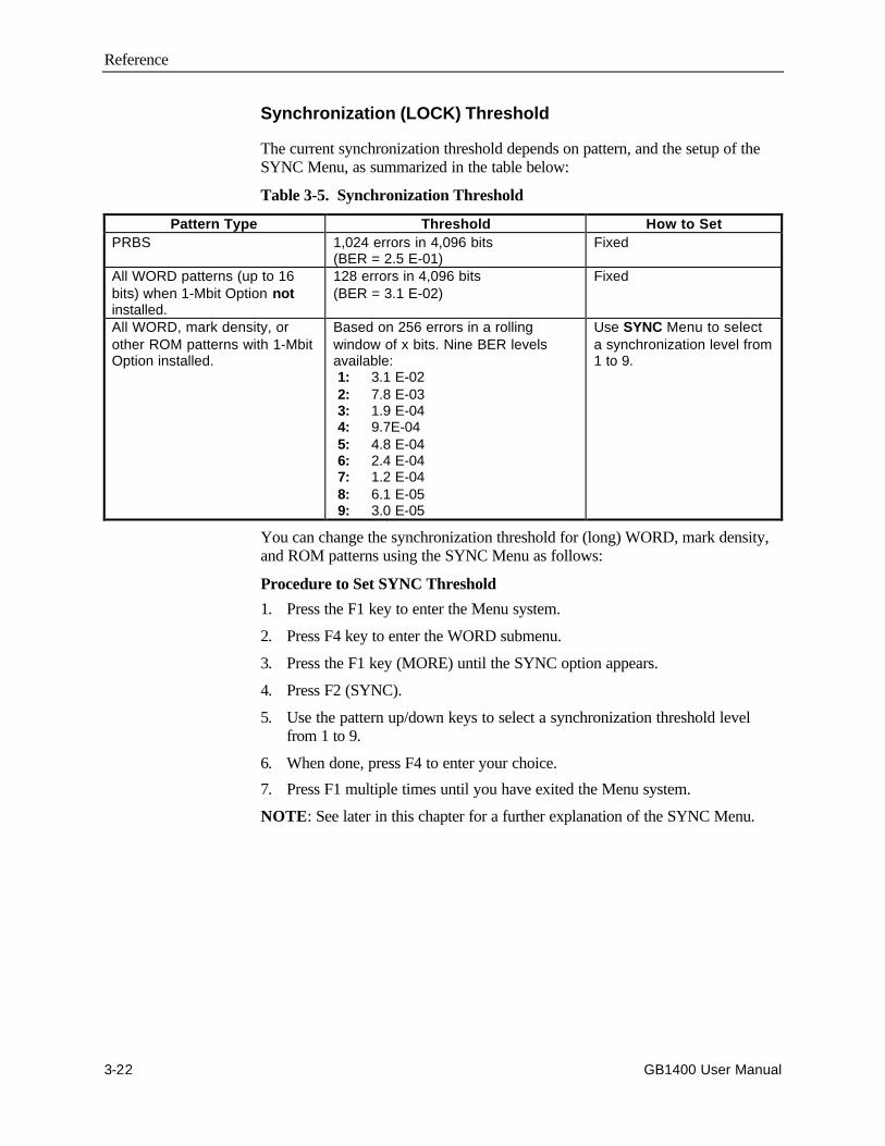
Reference
3-22 GB1400 User Manual
Synchronization (LOCK) Threshold
The current synchronization threshold depends on pattern, and the setup of theSYNC Menu, as summarized in the table below:
Table 3-5. Synchronization Threshold
Pattern Type Threshold How to SetPRBS 1,024 errors in 4,096 bits
(BER = 2.5 E-01)Fixed
All WORD patterns (up to 16bits) when 1-Mbit Option notinstalled.
128 errors in 4,096 bits(BER = 3.1 E-02)
Fixed
All WORD, mark density, orother ROM patterns with 1-MbitOption installed.
Based on 256 errors in a rollingwindow of x bits. Nine BER levelsavailable: 1: 3.1 E-02 2: 7.8 E-03 3: 1.9 E-04 4: 9.7E-04 5: 4.8 E-04 6: 2.4 E-04 7: 1.2 E-04 8: 6.1 E-05 9: 3.0 E-05
Use SYNC Menu to selecta synchronization level from1 to 9.
You can change the synchronization threshold for (long) WORD, mark density,and ROM patterns using the SYNC Menu as follows:
Procedure to Set SYNC Threshold
1. Press the F1 key to enter the Menu system.
2. Press F4 key to enter the WORD submenu.
3. Press the F1 key (MORE) until the SYNC option appears.
4. Press F2 (SYNC).
5. Use the pattern up/down keys to select a synchronization threshold levelfrom 1 to 9.
6. When done, press F4 to enter your choice.
7. Press F1 multiple times until you have exited the Menu system.
NOTE: See later in this chapter for a further explanation of the SYNC Menu.
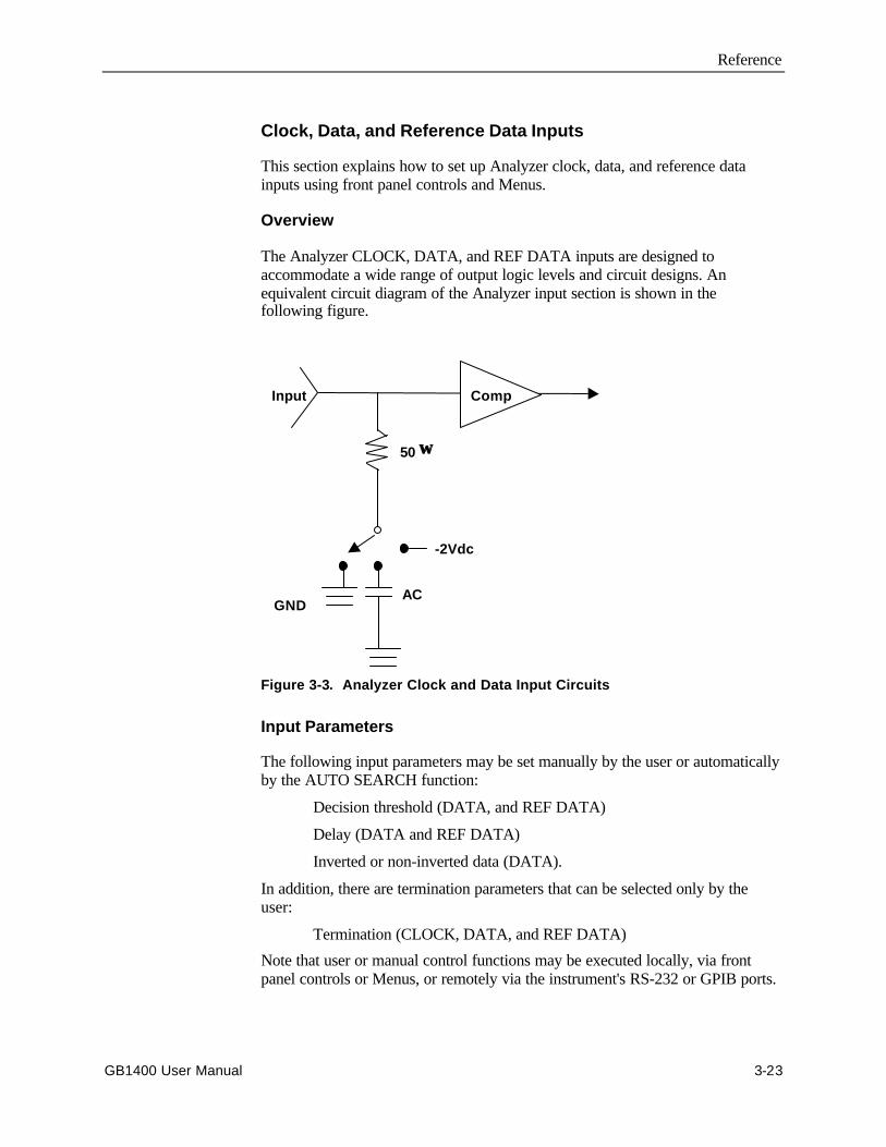
Reference
GB1400 User Manual 3-23
Clock, Data, and Reference Data Inputs
This section explains how to set up Analyzer clock, data, and reference datainputs using front panel controls and Menus.
Overview
The Analyzer CLOCK, DATA, and REF DATA inputs are designed toaccommodate a wide range of output logic levels and circuit designs. Anequivalent circuit diagram of the Analyzer input section is shown in thefollowing figure.
50 ΩΩ
-2Vdc
AC
Input Comp
GND
Figure 3-3. Analyzer Clock and Data Input Circuits
Input Parameters
The following input parameters may be set manually by the user or automaticallyby the AUTO SEARCH function:
Decision threshold (DATA, and REF DATA)
Delay (DATA and REF DATA)
Inverted or non-inverted data (DATA).
In addition, there are termination parameters that can be selected only by theuser:
Termination (CLOCK, DATA, and REF DATA)
Note that user or manual control functions may be executed locally, via frontpanel controls or Menus, or remotely via the instrument's RS-232 or GPIB ports.
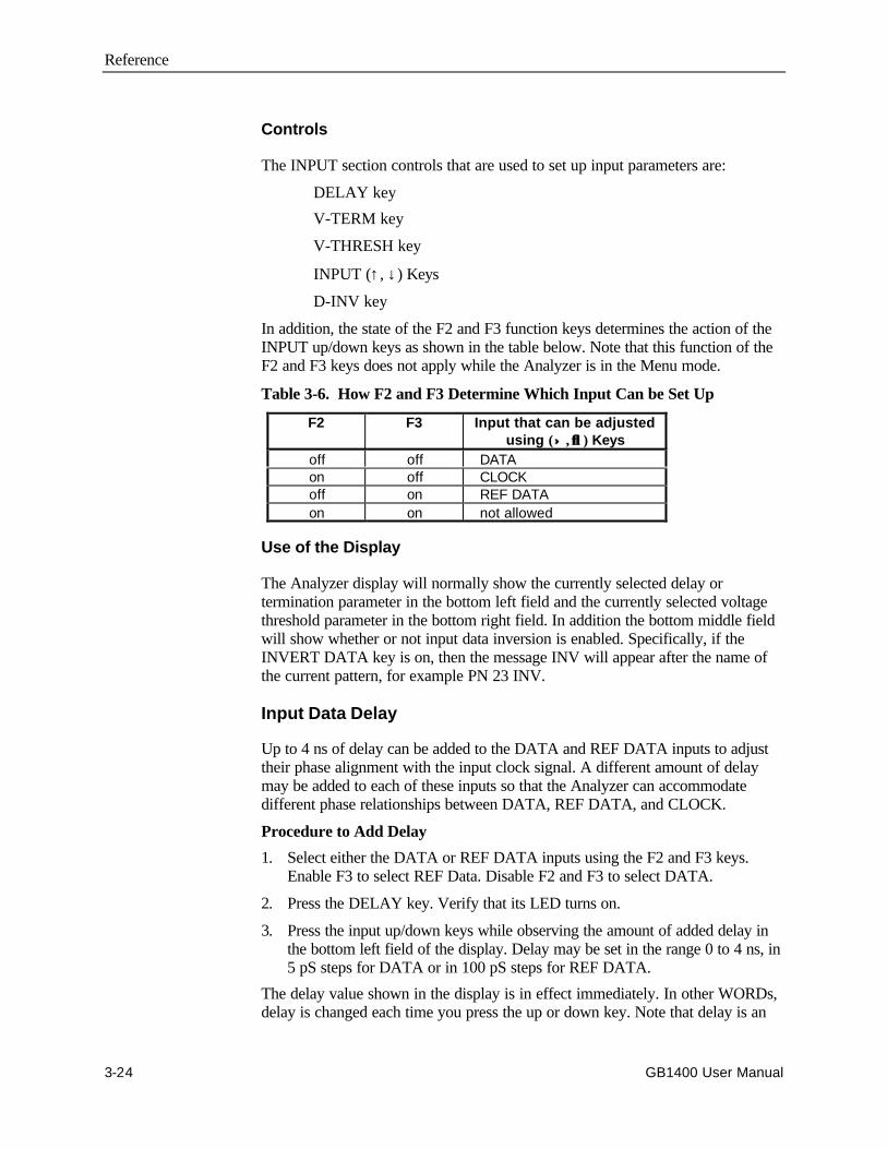
Reference
3-24 GB1400 User Manual
Controls
The INPUT section controls that are used to set up input parameters are:
DELAY key
V-TERM key
V-THRESH key
INPUT (↑, ↓) Keys
D-INV key
In addition, the state of the F2 and F3 function keys determines the action of theINPUT up/down keys as shown in the table below. Note that this function of theF2 and F3 keys does not apply while the Analyzer is in the Menu mode.
Table 3-6. How F2 and F3 Determine Which Input Can be Set Up
F2 F3 Input that can be adjustedusing (↑↑ , ↓↓ ) Keys
off off DATAon off CLOCKoff on REF DATAon on not allowed
Use of the Display
The Analyzer display will normally show the currently selected delay ortermination parameter in the bottom left field and the currently selected voltagethreshold parameter in the bottom right field. In addition the bottom middle fieldwill show whether or not input data inversion is enabled. Specifically, if theINVERT DATA key is on, then the message INV will appear after the name ofthe current pattern, for example PN 23 INV.
Input Data Delay
Up to 4 ns of delay can be added to the DATA and REF DATA inputs to adjusttheir phase alignment with the input clock signal. A different amount of delaymay be added to each of these inputs so that the Analyzer can accommodatedifferent phase relationships between DATA, REF DATA, and CLOCK.
Procedure to Add Delay
1. Select either the DATA or REF DATA inputs using the F2 and F3 keys.Enable F3 to select REF Data. Disable F2 and F3 to select DATA.
2. Press the DELAY key. Verify that its LED turns on.
3. Press the input up/down keys while observing the amount of added delay inthe bottom left field of the display. Delay may be set in the range 0 to 4 ns, in5 pS steps for DATA or in 100 pS steps for REF DATA.
The delay value shown in the display is in effect immediately. In other WORDs,delay is changed each time you press the up or down key. Note that delay is an
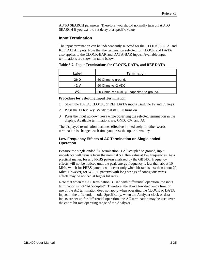
Reference
GB1400 User Manual 3-25
AUTO SEARCH parameter. Therefore, you should normally turn off AUTOSEARCH if you want to fix delay at a specific value.
Input Termination
The input termination can be independently selected for the CLOCK, DATA, andREF DATA inputs. Note that the termination selected for CLOCK and DATAalso applies to the CLOCK-BAR and DATA-BAR inputs. Available inputterminations are shown in table below.
Table 3-7. Input Terminations for CLOCK, DATA, and REF DATA
Label Termination
GND 50 Ohms to ground.
- 2 V 50 Ohms to -2 VDC.
AC 50 Ohms, via 0.01 µF capacitor, to ground.
Procedure for Selecting Input Termination
1. Select the DATA, CLOCK, or REF DATA inputs using the F2 and F3 keys.
2. Press the TERM key. Verify that its LED turns on.
3. Press the input up/down keys while observing the selected termination in thedisplay. Available terminations are: GND, -2V, and AC.
The displayed termination becomes effective immediately. In other words,termination is changed each time you press the up or down key.
Low-Frequency Effects of AC Termination on Single-endedOperation
Because the single-ended AC termination is AC-coupled to ground, inputimpedance will deviate from the nominal 50 Ohm value at low frequencies. As apractical matter, for any PRBS pattern analyzed by the GB1400, frequencyeffects will not be noticed until the peak energy frequency is less than about 10MHz, which for PRBS patterns will occur only when bit rate is less than about 20Mb/s. However, for WORD patterns with long strings of contiguous zeros,effects may be noticed at higher bit rates.
Note that when the AC termination is used with differential operation, the inputtermination is not "AC-coupled". Therefore, the above low-frequency limit onuse of the AC termination does not apply when operating the CLOCK or DATAinputs in the differential mode. Specifically, when the Analyzer clock or datainputs are set up for differential operation, the AC termination may be used overthe entire bit rate operating range of the Analyzer.

Reference
3-26 GB1400 User Manual
Input Decision Threshold
The input decision thresholds of the DATA, and REF DATA inputs can beindependently adjusted. However, it is important to note that input thresholdadjustment applies only for single-ended operation. When operating Analyzerdata inputs in the differential mode, their input decision threshold effectivelybecomes the average of the positive peak and negative peak voltage levels and isnot adjustable by the user.
Procedure to Adjust (Single-ended) Input Decision Threshold:
1. Verify that the selected input is set up for singled-ended operation. ForDATA operation, connect a cable from rear panel threshold to front NOT-DATA (DATA-BAR) input.
2. Select either the DATA, CLOCK, or REF DATA input using the F2 and F3keys.
3. Press the THRESH key. Verify that its LED turns on.
4. Press the input up/down keys while observing selected threshold value in thebottom, right field of the display. Decision threshold setup range is a functionof input termination as shown in table below.
Table 3-8. Input Threshold Range as a Function of Termination
Selected Termination Threshold Setup Range
GND - 1.5 to + 1.0 VDC, 50 mV steps
- 2 V - 2.5 to + 0.0 VDC, 50 mV steps
AC - 1.5 to + 1.0 VDC, 50 mV steps
The displayed threshold takes effect immediately. In other WORDs, threshold isincremented or decremented each time you press the up or down key. Note thatthreshold is an AUTO SEARCH parameter. So be sure turn off AUTO SEARCHif you want to fix delay at a specific value.
Logically Inverting Input Data
The INPUT section INVERT key may be used to logically invert the input datapattern, that is change all 1s to 0s and 0s to 1s. If the INVERT key is off, then theinput data pattern is not inverted. However if the INVERT key is on, the inputdata pattern is logically inverted. You can toggle input data inversion on or off bypressing the INVERT DATA key. Note that logically inverting the input patternis equivalent to swapping the connections to the DATA and DATA-BAR inputs.
To toggle input data inversion on or off, press the INVERT key.
Reference
GB1400 User Manual 3-27
Singled-ended or Differential Operation
Analyzer clock and data inputs can be operated in a singled-ended or differentialmode. Differential operation provides greater immunity to ground noise andEMI. Note that threshold setup applies to the clock and data inputs only whenthey are operated in the singled-ended mode. When the clock or data input isoperated in the differential mode, its input threshold effectively becomes theaverage of the positive peak and negative peak voltage of the received true andcomplement signals.
Procedure to Configure CLOCK or DATA Inputs for Single-EndedOperation
1. Connect Clock signal to CLOCK input.
2. Connect Data signal to DATA input.
3. Connect cable from rear panel DATA THRESHOLD output to front panelDATA BAR input.
Selecting the Reference Data Mode
In most testing applications, the Analyzer is set up to compare the received datapattern with a data pattern generated internally by the Analyzer. However youmay also set up the Analyzer to compare two externally generated patterns. Thismakes it possible to analyze framed or proprietary signals that cannot easily besimulated as long WORD patterns.
To configure the Analyzer for reference data testing, the primary or test signalmust be connected to the Analyzer data input (which may be set up for singled-ended or differential operation) while the reference signal is connected to theREF DATA input. Then the Reference Data mode must be selected using theEXT key. Note that the reference signal must be generated by a singled-endedoutput.
Procedure for Selecting the Reference Data Mode
1. Connect a test signal to the Analyzer data input and a reference signal to theREF input.
2. Press the Analyzer EXT key to toggle the reference mode on. Verify that theEXT key turns on.
3. To de-select the reference mode, press the EXT key again. Verify that theEXT key turns off.
Reference
3-28 GB1400 User Manual
Monitor Outputs
The MONITOR CLOCK and DATA outputs are provided so that you canmonitor the test signal as seen by the Analyzer. This allows you to attach an errorlogging device, for example, to record the exact times that errors occur. Or, youmay attach another type of instrument to make specialized calculations.
MONITOR DATA is an NRZ output signal with the same bit sequence as thatrecovered by the Analyzer front end circuit. MONITOR CLOCK is thecorresponding clock signal. Because the MONITOR output is a regeneratedversion of the received test signal, bit errors reported by the Analyzer—due tonoise on the received data (or clock) signals—will be present in the MONITORDATA output bit sequence.
Output Setup
All three MONITOR ports (CLOCK, DATA, and Pattern Sync) are 50 Ohm,single-ended outputs.
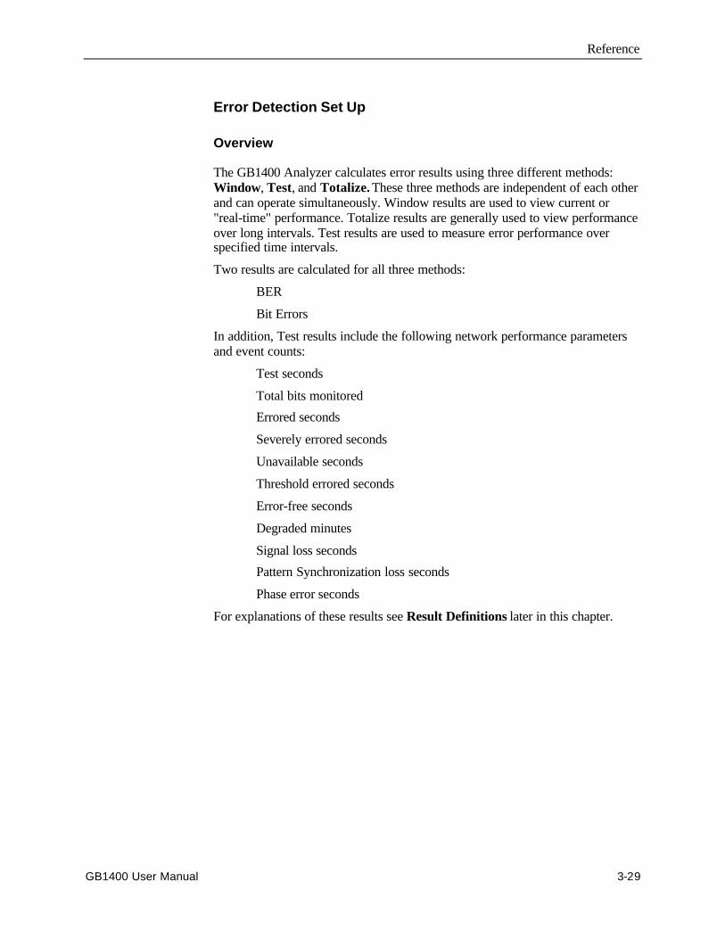
Reference
GB1400 User Manual 3-29
Error Detection Set Up
Overview
The GB1400 Analyzer calculates error results using three different methods:Window, Test, and Totalize. These three methods are independent of each otherand can operate simultaneously. Window results are used to view current or"real-time" performance. Totalize results are generally used to view performanceover long intervals. Test results are used to measure error performance overspecified time intervals.
Two results are calculated for all three methods:
BER
Bit Errors
In addition, Test results include the following network performance parametersand event counts:
Test seconds
Total bits monitored
Errored seconds
Severely errored seconds
Unavailable seconds
Threshold errored seconds
Error-free seconds
Degraded minutes
Signal loss seconds
Pattern Synchronization loss seconds
Phase error seconds
For explanations of these results see Result Definitions later in this chapter.
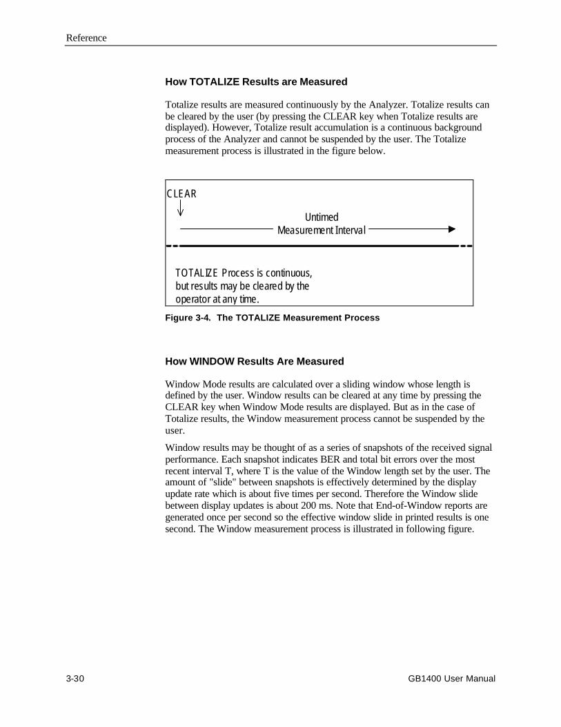
Reference
3-30 GB1400 User Manual
How TOTALIZE Results are Measured
Totalize results are measured continuously by the Analyzer. Totalize results canbe cleared by the user (by pressing the CLEAR key when Totalize results aredisplayed). However, Totalize result accumulation is a continuous backgroundprocess of the Analyzer and cannot be suspended by the user. The Totalizemeasurement process is illustrated in the figure below.
CLEAR
UntimedMeasurement Interval
TOTALIZE Process is continuous,but results may be cleared by theoperator at any time.
Figure 3-4. The TOTALIZE Measurement Process
How WINDOW Results Are Measured
Window Mode results are calculated over a sliding window whose length isdefined by the user. Window results can be cleared at any time by pressing theCLEAR key when Window Mode results are displayed. But as in the case ofTotalize results, the Window measurement process cannot be suspended by theuser.
Window results may be thought of as a series of snapshots of the received signalperformance. Each snapshot indicates BER and total bit errors over the mostrecent interval T, where T is the value of the Window length set by the user. Theamount of "slide" between snapshots is effectively determined by the displayupdate rate which is about five times per second. Therefore the Window slidebetween display updates is about 200 ms. Note that End-of-Window reports aregenerated once per second so the effective window slide in printed results is onesecond. The Window measurement process is illustrated in following figure.
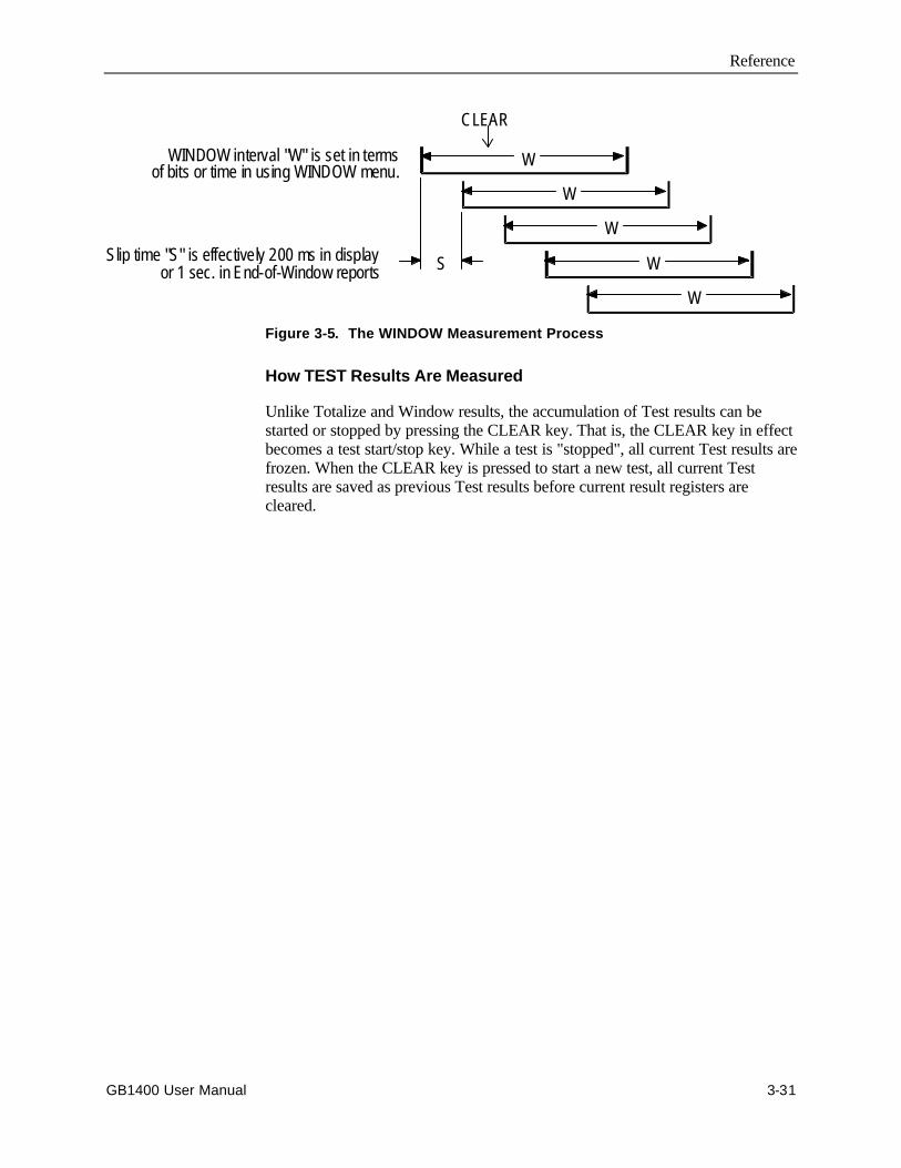
Reference
GB1400 User Manual 3-31
CLEAR
W
W
W
W
W
SSlip time "S" is effectively 200 ms in displayor 1 sec. in End-of-Window reports
WINDOW interval "W" is set in termsof bits or time in using WINDOW menu.
Figure 3-5. The WINDOW Measurement Process
How TEST Results Are Measured
Unlike Totalize and Window results, the accumulation of Test results can bestarted or stopped by pressing the CLEAR key. That is, the CLEAR key in effectbecomes a test start/stop key. While a test is "stopped", all current Test results arefrozen. When the CLEAR key is pressed to start a new test, all current Testresults are saved as previous Test results before current result registers arecleared.
Reference
3-32 GB1400 User Manual
As shown in the next figure, Test results may be calculated using one of threetiming modes: Timed, Untimed, or Repeat.
T EST Measurement Process
Untimed T EST Process:Intervals started and
stopped manually by operator.
Timed TEST Process:Interv als started by
operator, stopped auto-matically at end of interval T.
Repeat Timed TEST Process:Process started by operator,intervals of length T stoppedand re-s tarted automatically.
CLEAR
CLEAR CLEAR CLEAR
CLEAR
T T T
T T T T T
UntimedMeasurement Interval
TEST interval "T" set in terms oftime (hrs:min:sec) in TEST menu.
Figure 3-6. The TEST Measurement Process
Timed Tests. When the Timed mode is selected, the Analyzer will automaticallystop accumulating Test results after the test interval (specified by the user) haselapsed. All Test results will be frozen until the CLEAR key is pressed to begin anew test.
Repeat (Timed) Tests. When the Repeat mode is selected, the Analyzer willautomatically stop and then restart a test after a user specified test length haselapsed. This process will continue until the user presses the CLEAR key tomanually stop Test result accumulation.
Untimed Tests. When the Untimed mode is selected, the Analyzer will continueto collect Test results until the CLEAR key is pressed. At this point Test resultswill remain frozen until the CLEAR key is pressed again to start a new test.
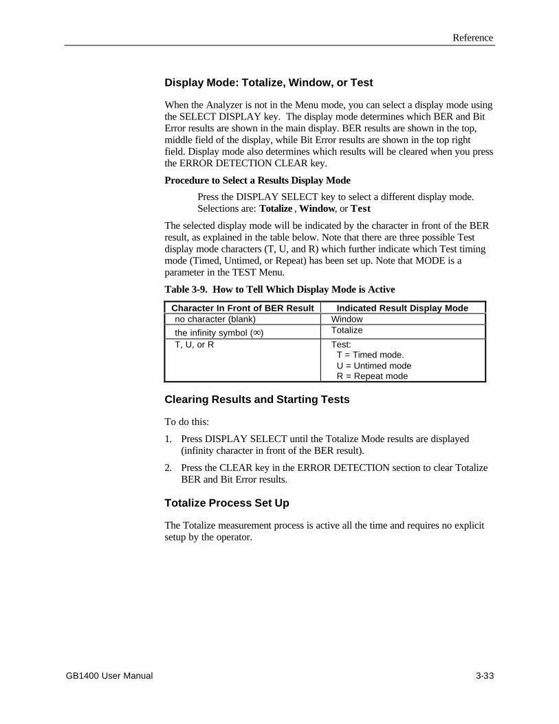
Reference
GB1400 User Manual 3-33
Display Mode: Totalize, Window, or Test
When the Analyzer is not in the Menu mode, you can select a display mode usingthe SELECT DISPLAY key. The display mode determines which BER and BitError results are shown in the main display. BER results are shown in the top,middle field of the display, while Bit Error results are shown in the top rightfield. Display mode also determines which results will be cleared when you pressthe ERROR DETECTION CLEAR key.
Procedure to Select a Results Display Mode
Press the DISPLAY SELECT key to select a different display mode.Selections are: Totalize , Window, or Test
The selected display mode will be indicated by the character in front of the BERresult, as explained in the table below. Note that there are three possible Testdisplay mode characters (T, U, and R) which further indicate which Test timingmode (Timed, Untimed, or Repeat) has been set up. Note that MODE is aparameter in the TEST Menu.
Table 3-9. How to Tell Which Display Mode is Active
Character In Front of BER Result Indicated Result Display Mode no character (blank) Window the infinity symbol (∞) Totalize
T, U, or R Test: T = Timed mode. U = Untimed mode R = Repeat mode
Clearing Results and Starting Tests
To do this:
1. Press DISPLAY SELECT until the Totalize Mode results are displayed(infinity character in front of the BER result).
2. Press the CLEAR key in the ERROR DETECTION section to clear TotalizeBER and Bit Error results.
Totalize Process Set Up
The Totalize measurement process is active all the time and requires no explicitsetup by the operator.
Reference
3-34 GB1400 User Manual
Window Process Set Up
The Window measurement process may be configured using the four parametersin the WINDOW Menu:
MODE: Defines window length in terms of "bits" or "seconds".
BITS: Window length in bits.
SECOND: Window length in terms of hours, minutes, and seconds.
REPORT: Turns end-of-window reports on or off.
If you want to measure Window results, you must set the MODE parameter, anddepending on your MODE selection, either the BITS or SECOND parameter. Inaddition, if you want to generate end-of-window reports you must also set theREPORT parameter to on.
Procedure
1. Press F1 to enter the Menu system.
2. Select the WINDOW Menu (F3).
3. Within the WINDOW Menu, set up:
a. MODE (F2) and
b. either BITS (F3) or SECOND (F4).
4. Press MORE (F1) to see the next page of the WINDOW Menu.
5. If you are using a printer, set the REPORT parameter (F2) to on or off asrequired.
6. When WINDOW Menu setup is complete, press F1 multiple times to exitthe Menu system.
See later in the this chapter for more information on setting up the WINDOWMenu.
Reference
GB1400 User Manual 3-35
Test Process Set Up
The TEST Menu contains the following six selections:
LENGTH: Test length: hours, minutes, seconds.
MODE: Test timing mode: Timed, Untimed, or Repeat.
REPORT: Test reporting mode: None, Print On Error, or Both.
THRESH: Threshold for the TES (threshold errored second) result.
SQUEL: On Error report squelch after 10 consecutive seconds: yes or no.
PRINT: Use this function to print current Test results immediately.
If you want to collect TEST results, you must set LENGTH and MODE beforeyou begin a test. And if you are using a printer you should set the REPORTparameter as desired. Note that On Error reports can generate a lot of paper, soselect On Error or Both with caution. Setup of the other parameters in the TESTMenu are optional.
Procedure
1. Press F1 to access the Menu system.
2. Select the TEST Menu (F2).
3. Within the TEST Menu, set up:
a. LENGTH (F2) and
b. MODE (F3).
4. And, if you are using a printer, set up the REPORT parameter (F4).
5. Press MORE (F1) to see the next page of the TEST Menu. Review thesetup of the THRES (F2) and SQUEL (F3) parameters. Change ifnecessary.
NOTE: Setting SQUEL (squelch) to ON is recommended.
6. Press the F1 key multiple times to exit the Menu system.
See later in this chapter for more information of setting up the TEST Menu.
Reference
3-36 GB1400 User Manual
Viewing Results
BER and bit error results are shown in the normal display mode. However toview the complete list of Test results, you must use the TEST Menu VIEW-CURor VIEW-PRE functions.
BER and Bit Errors
The Analyzer calculates BER and bit errors using all three measurement methods(Totalize, Window, and Test). The current display mode determines whichBER/bit error result pair is shown in the display. Note that BER is shown in thetop, middle field while the bit error result is shown in the top, right field.
Procedure to View Desired BER and Bit Error Results
Press the DISPLAY SELECT key to select the appropriate display mode.
As noted earlier, the character in front of the BER result will indicate the currentdisplay mode. The infinity symbol (∞) indicates Totalize; a blank characterindicates Window; and the T, U, or R characters indicate Test results which havebeen measured using the timed, untimed, or repeat timing modes respectively.
All Other Results (Test Process only)
To view the complete set of Test results, select the VIEW-CUR or VIEW-PREfunctions from the TEST Menu. VIEW-CUR will show partial results if a timedtest is in progress, or results from the last completed test. VIEW-PRE will showresults saved in the "previous" test registers. These results are over-written withthe contents of the current registers each time a test is completed.
Procedure
1. Press F1 to enter the Menu system.
2. Select the TEST Menu (F2).
3. Press MORE (F1) twice to view the third page of the TEST Menu.
4. Select either VIEW-CUR or VIEW-PRE to view all current or previousTest results respectively. Once inside either the VIEW-CUR or VIEW-PRE function, use the pattern up/down keys to scroll through the resultslist.
5. When done, press F1 multiple times to exit the Menu system.
See later in this chapter for more information on the TEST Menu. Also seeMeasurement Definitions , later in this chapter.
Reference
GB1400 User Manual 3-37
Printing Results (Reports)
A serial or parallel printer may be connected to the Analyzer's RS-232-C orPRINTER ports respectively. Note that you cannot connect a GPIB printerdirectly to the GPIB port; but you may "print" results to a GPIB controller, whichcan store reports for later viewing or printing.
Basic Report Setup Procedure
The following initial setup procedure must be performed in order to generate anytype of Analyzer report.
1. Connect your printer to the Analyzer RS-232 or PRINTER ports asappropriate. (See Chapter 6 for details).
2. Press F1 to enter the Menu system.
3. Select MORE (F1) to view the second page of the main Menu.
4. Set up the appropriate hardware port as follows:
a. If you are using a serial printer, select RS232 (F2) to set up theserial port.
b. If you are "printing" to a GPIB controller, select GPIB (F3) to setup the GPIB port
NOTE: The Analyzer PRINTER port is a standard PC-type parallel port whichrequires no hardware setup.
5. Next, select the PRINT parameter (F4).
a. Set the PORT parameter to Parallel, GPIB, or Serial.
b. Set the ON/OFF parameter to ON to enable reports.
NOTE: The PRINT ON/OFF parameter must be set to ON to print any type ofreport.
6. When you have completed all desired setup changes, press F1 multipletimes to exit the Menu system.
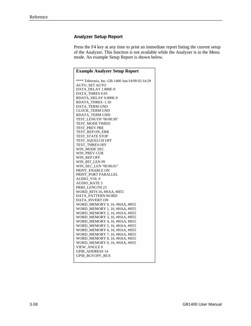
Reference
3-38 GB1400 User Manual
Analyzer Setup Report
Press the F4 key at any time to print an immediate report listing the current setupof the Analyzer. This function is not available while the Analyzer is in the Menumode. An example Setup Report is shown below.
Example Analyzer Setup Report
**** Tektronix, Inc. GB-1400 Jun/14/99 02:14:29AUTO_SET AUTODATA_DELAY 1.800E-9DATA_THRES 0.05RDATA_DELAY 0.000E-9RDATA_THRES -1.50DATA_TERM GNDCLOCK_TERM GNDRDATA_TERM GNDTEST_LENGTH "00:00:30"TEST_MODE TIMEDTEST_PREV PRETEST_REP ON_ERRTEST_STATE STOPTEST_SQUELCH OFFTEST_THRES OFFWIN_MODE SECWIN_PREV CURWIN_REP OFFWIN_BIT_LEN 09WIN_SEC_LEN "00:00:01"PRINT_ENABLE ONPRINT_PORT PARALLELAUDIO_VOL 0AUDIO_RATE 3PRBS_LENGTH 23WORD_BITS 16, #HAA, #H55DATA_PATTERN WORDDATA_INVERT ONWORD_MEMORY 0, 16, #HAA, #H55WORD_MEMORY 1, 16, #HAA, #H55WORD_MEMORY 2, 16, #HAA, #H55WORD_MEMORY 3, 16, #HAA, #H55WORD_MEMORY 4, 16, #HAA, #H55WORD_MEMORY 5, 16, #HAA, #H55WORD_MEMORY 6, 16, #HAA, #H55WORD_MEMORY 7, 16, #HAA, #H55WORD_MEMORY 8, 16, #HAA, #H55WORD_MEMORY 9, 16, #HAA, #H55VIEW_ANGLE 0GPIB_ADDRESS 14GPIB_BUS OFF_BUS
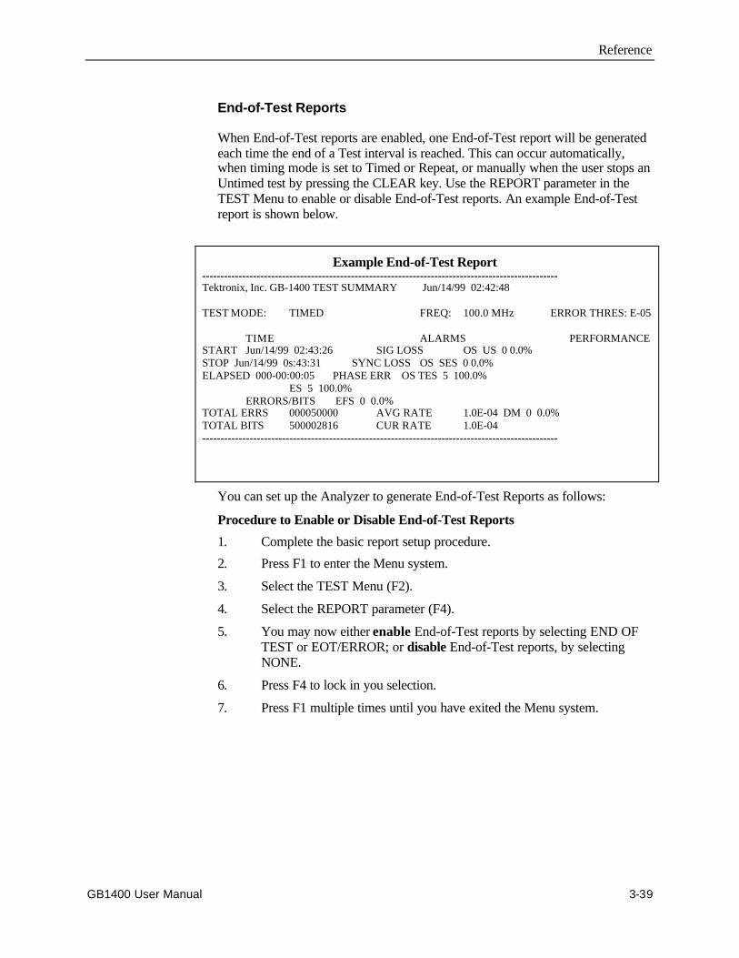
Reference
GB1400 User Manual 3-39
End-of-Test Reports
When End-of-Test reports are enabled, one End-of-Test report will be generatedeach time the end of a Test interval is reached. This can occur automatically,when timing mode is set to Timed or Repeat, or manually when the user stops anUntimed test by pressing the CLEAR key. Use the REPORT parameter in theTEST Menu to enable or disable End-of-Test reports. An example End-of-Testreport is shown below.
Example End-of-Test Report--------------------------------------------------------------------------------------------------Tektronix, Inc. GB-1400 TEST SUMMARY Jun/14/99 02:42:48
TEST MODE: TIMED FREQ: 100.0 MHz ERROR THRES: E-05
TIME ALARMS PERFORMANCESTART Jun/14/99 02:43:26 SIG LOSS OS US 0 0.0%STOP Jun/14/99 0s:43:31 SYNC LOSS OS SES 0 0.0%ELAPSED 000-00:00:05 PHASE ERR OS TES 5 100.0%
ES 5 100.0%ERRORS/BITS EFS 0 0.0%
TOTAL ERRS 000050000 AVG RATE 1.0E-04 DM 0 0.0%TOTAL BITS 500002816 CUR RATE 1.0E-04--------------------------------------------------------------------------------------------------
You can set up the Analyzer to generate End-of-Test Reports as follows:
Procedure to Enable or Disable End-of-Test Reports
1. Complete the basic report setup procedure.
2. Press F1 to enter the Menu system.
3. Select the TEST Menu (F2).
4. Select the REPORT parameter (F4).
5. You may now either enable End-of-Test reports by selecting END OFTEST or EOT/ERROR; or disable End-of-Test reports, by selectingNONE.
6. Press F4 to lock in you selection.
7. Press F1 multiple times until you have exited the Menu system.

Reference
3-40 GB1400 User Manual
End-of-Window Reports
When enabled, an End-of-Window report will occur once every second. Theresults of an End-of-Window report are based on a sliding interval T, where T isset in terms of bits or time (hours:minutes:seconds). Use the REPORT parameterin the WINDOW Menu to enable or disable End-of-Window reports. Use theMODE, BITS, and SECOND parameters in the WINDOW Menu to set windowlength T. An example End-of-Window report is shown below.
Example End-of-Window ReportDate: Jun/14/99 Time: 02:42:34.46 Bits= 5.00E+08 Errs= 5000 Err rate= 1.0E-04 Freq= 100.00 MHz Pattern= AA55 Data los= 0 Sync Los= 0 Phase Err= 0
Procedure to Enable or Disable End-of-Window Reports
1. Complete the Basic Report Setup Procedure.
2. Press F1 to enter the Menu system.
3. Select the WINDOW Menu (F3).
4. Press F1 to see the second page of the WINDOW Menu.
5. Select the REPORT parameter (F2).
6. Set the REPORT parameter to ON. Press F4 to lock in this choice.
7. Exit the Menu system by pressing F1 multiple times until the normaldisplay format appears.
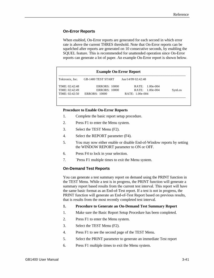
Reference
GB1400 User Manual 3-41
On-Error Reports
When enabled, On-Error reports are generated for each second in which errorrate is above the current THRES threshold. Note that On-Error reports can besquelched after reports are generated on 10 consecutive seconds, by enabling theSQUEL feature. This is recommended for unattended operation since On-Errorreports can generate a lot of paper. An example On-Error report is shown below.
Example On-Error Report-------------------------------------------------------------------------------------------------------------------------Tektronix, Inc. GB-1400 TEST START Jun/14/99 02:42:48
TIME: 02:42:48 ERRORS: 10000 RATE: 1.00e-004TIME: 02:42:49 ERRORS: 10000 RATE: 1.00e-004 SynLosTIME: 02:42:50 ERRORS: 10000 RATE: 1.00e-004-------------------------------------------------------------------------------------------------------------------------
Procedure to Enable On-Error Reports
1. Complete the basic report setup procedure.
2. Press F1 to enter the Menu system.
3. Select the TEST Menu (F2).
4. Select the REPORT parameter (F4).
5. You may now either enable or disable End-of-Window reports by settingthe WINDOW REPORT parameter to ON or OFF.
6. Press F4 to lock in your selection.
7. `Press F1 multiple times to exit the Menu system.
On-Demand Test Reports
You can generate a test summary report on demand using the PRINT function inthe TEST Menu. While a test is in progress, the PRINT function will generate asummary report based results from the current test interval. This report will havethe same basic format as an End-of-Test report. If a test is not in progress, thePRINT function will generate an End-of-Test Report based on previous results,that is results from the most recently completed test interval.
1. Procedure to Generate an On-Demand Test Summary Report
1. Make sure the Basic Report Setup Procedure has been completed.
2. Press F1 to enter the Menu system.
3. Select the TEST Menu (F2).
4. Press F1 to see the second page of the TEST Menu.
5. Select the PRINT parameter to generate an immediate Test report
6. Press F1 multiple times to exit the Menu system.

Reference
3-42 GB1400 User Manual
Result Definitions
The following section defines all results calculated by the Analyzer.
BER and Bit Errors
The following two results are calculated by all three Analyzer measurementprocesses (Totalize, Window, and Test):
Bit Errors : The total number of bit (logic) errors counted in themeasurement interval. May be based on Totalize, Window, or Testmeasurement intervals.
Bit Error Rate (BER): Also known as "bit error ratio". May be based onTotalize, Window, or Test measurement intervals. Equals the number ofbit errors divided by the total number of bits in the measurement interval:
BER = TE / TB
where: TE = total number of bit errors in the intervalTB = total number of bits in the interval
Note that BER results, when included in End-of-Test or Immediate Test Reports,are identified as follows:
AVE RATE: BER calculated over the entire TEST interval.
CUR RATE: BER calculated over the latest WINDOW interval.
All Other Results (Test Intervals Only)
The following results are calculated over Test intervals only. You can view allTest results using the VIEW-CUR and VIEW-PRE functions in the TEST Menu.Or, you can print all Test results at the end of Test intervals or immediately,using the REPORT or PRINT functions respectively in the TEST Menu.
SIG LOSS: The number of 20 ms intervals in which the Analyzer inputactivity detector sees no transitions on the input CLOCK signal for 20ms.
SYNC LOSS: The number of 20 ms intervals in which patternsynchronization (lock) is lost.
PHASE ERR: The number of 20 ms intervals in which a phase errorevent is detected. The Analyzer will report a phase error when the activeclock edge moves too close to the data waveform transition point, thusviolating the input circuit setup or hold time.

Reference
GB1400 User Manual 3-43
Errored Seconds (ES): The number of seconds in the measurementinterval containing one or more errors. The GB1400 measuresasynchronous errored seconds—that is one second intervals based on theinstrument's internal clock rather than the detection of an error. Erroredseconds are not counted during unavailable time (see below). However,the errored second count does include both severely errored seconds andnon-severely errored seconds.
ES = TSE - US
TSE = total seconds in the current measurement interval withone or more errors.
US = unavailable seconds in the current interval
% Errored Seconds (%ES): Errored seconds as a percentage of thetotal number of seconds in the measurement interval:
%ES = ( ES / TS ) * 100%
ES = errored seconds in the measurement interval
TS = total seconds in the measurement interval
Error Free Seconds (EFS): The number of seconds that contain noerrors and are not unavailable.
EFS = (TS - ES - US)
TS = total seconds in the measurement interval
ES = errored seconds in the measurement interval
US = unavailable seconds in the measurement interval
%EFS: Percentage Error-free Seconds. Error-free seconds as apercentage of the total number of seconds in the measurement interval.
% EFS = ( EFS / TS) * 100%
EFS = error-free seconds in the measurement interval
TS = total seconds in the measurement interval
Severely Errored Seconds (SES): The number of errored seconds in themeasurement interval which BER is greater than or equal to 1E-03,excluding unavailable seconds. For example, on a 100 Mb/s test signal,this would include all available, synchronous errored seconds with100,000 or more errors.
SES = (seconds with BER ≥ 1E-03) - US
US = unavailable seconds in the current interval

Reference
3-44 GB1400 User Manual
TES: Threshold Errored Seconds: The number of seconds in themeasurement interval in which BER exceeds the threshold set by theTHRES parameter in the TEST Menu, minus the number of unavailableseconds. Available threshold values are 1E-n, where n = 2, 3, ... 16.
TES = (seconds with BER ≥ Threshold) - US
US = unavailable seconds in the current interval
Degraded Minutes (DM): The number of 60 second intervals in thecurrent interval in which the BER exceeds the current test threshold(THRES).
Percentage Degraded Minutes (%DM): The number of degradedminutes expressed as a percentage of the total number of minutes in themeasurement interval.
% DM = ( DM / TM) * 100%
DM = degraded minutes in the measurement interval
TM = total minutes in the measurement interval
Unavailable Seconds (US): The number of seconds in unavailableintervals. Unavailable intervals start upon the detection of 10 contiguousseverely errored seconds (SES), and end upon the detection of 10 non-severely errored seconds.
Percentage Unavailable Seconds (%US): The number of unavailableseconds expressed as a percentage of total seconds in the measurementinterval.
% US = ( US / TS) * 100%
US = unavailable seconds in the measurement interval
TS = total seconds in the measurement interval
Error History Indicators
CLEARSYNC LOSSBITPHASEPOWER
The Analyzer (performance) history indicators arelocated in the ERROR HISTORY section of the frontpanel. These indicators will latch on when the indicatedevent occurs, and can be cleared by the user.
SYNC LOSS: This indicator will turn on if the LOCK LED turns off;that is if the BER rises above the current synchronization threshold (SeeSynchronization (LOCK) Threshold in Chapter 4)
BIT: Will turn on if a bit error is detected.
PHASE: Will turn on if a phase error is detected. The Analyzer willreport a phase error when the active clock edge moves too close to thedata waveform transition point thus violating the input circuit setup orhold time.
POWER: Will turn on after a power loss has occurred.
Reference
GB1400 User Manual 3-45
CLEAR Control
Pressing the CLEAR key will reset all active history indicators. Note that whenyou start a test, you must clear test results and history indicators by pressing theERROR DETECTION CLEAR and ERROR HISTORY CLEAR keysrespectively.
Audio (Beeper) Function
The Analyzer may be set up to "beep" each time a second is detected in whichBER is above a specified threshold. The AUDIO VOL and RATE controls areused to configure this function.
Procedure To Set Up the Audio Alert Function
1. Press the AUDIO RATE up or down keys to increment or decrement thecurrent audio alert BER threshold. The current value of the AUDIORATE will be displayed in the bottom, right field of the display for aboutseven seconds after the last key press. Available selections are 1E-x,where x = 2, 3, ... 16
2. Press the AUDIO VOL up or down keys to increment or decrement thecurrent audio alert volume. There are four volume levels. The minimumvalue is "OFF". Except when volume is set to the minimum level, a beepwill occur each time you press an AUDIO VOL up or down key toindicate the current volume.
Analyzer Error Messages
When abnormal input conditions are detected, the Analyzer will display variouserror messages to indicate an unusual condition. These are explained below.
NO CLOCK: This message will appear in the frequency field (top, left)if no activity is detected at the CLOCK input for 20 ms.
NO DATA: This message will appear in the BER field (top, middle) ifno activity is detected at the data (or clock) input for 20 ms.
LOW AMP: May appear when no signal or a low-signal is applied to theCLOCK or DATA input and AUTO_SEARCH is enabled
Reference
3-46 GB1400 User Manual
Starting and Stopping Measurements
The following section explains how to start and stop TEST measurements, andhow to initialize or "re-start" WINDOW and TOTALIZE measurements.
The TEST measurement process has two states: started and stopped . In thestarted or active state, new "current" results are accumulated while all resultsfrom the previous TEST interval are saved in memory. In the stopped state, allcurrent results are frozen so that in effect the results from the last two TESTintervals are saved in memory.
You can tell whether the current TEST process is started or stopped by observingthe TEST character (T, U, or R) in the display. If the displayed TEST character(in front of the BER result) is blinking, then the TEST process is stopped andcurrent results are frozen. On the other hand, if the TEST character is notblinking, that is if it is on steady, then the current TEST process is started andnew results are accumulating.
You can start and stop TEST measurements as follows:
Procedure for Starting the TEST Measurement Process
1. Configure your Analyzer and Generator as desired. In particular, select aTEST timing mode: Timed, Untimed, or Repeat.
2. Use the DISPLAY SELECT key to set the display mode to TEST. Verifythat the expected TEST character (T, U, or R) is shown.
3 If the TEST character is blinking, press the ERROR DETECTIONCLEAR key to stop the TEST process.
3. At this point you may press the ERROR DETECTION CLEAR key tostart a new TEST process at any time. After pressing CLEAR, verify thatthe displayed TEST character is no longer blinking. After starting a newTEST interval you may also reset the bit, phase, and power historyindicators by pressing the ERROR HISTORY CLEAR key.
Regardless of the current TEST timing mode, you can stop an active TESTprocess as follows:
Procedure for Stopping the TEST Process
1. Use the DISPLAY SELECT key to set the display mode to TEST. Verifythat the expected TEST character (T, U, or R) is shown.
2 Observe the TEST character.
a. If the character is on steady, then you may stop the current TESTinterval by pressing the ERROR DETECTION CLEAR key.
b. However, if the character is blinking then the TEST process isalready stopped and you should not press the CLEAR key untilyou want to start a new TEST interval.
Note that TEST measurement starting and stopping can be controlled manuallyor automatically, depending on the selected timing mode. When the Untimed

Reference
GB1400 User Manual 3-47
mode is selected, TEST intervals must be started and stopped manually by theuser. When the Timed mode is selected, TEST intervals are started manually, butstopped automatically after an interval determined by the LENGTH parameter inthe TEST Menu. When the Repeat timing mode is selected, once the TESTprocess has been started by the user, new TEST intervals are stopped and then re-started automatically, at intervals determined by the LENGTH parameter.However, even when the Repeat mode is selected, the overall TEST process cancontrolled by the user, that is started and stopped manually.
Starting New Totalize and Window Measurement Intervals
Unlike the TEST process, the Totalize and Window measurement processes arecontinuous background processes that cannot be stopped and started by the user.However you can clear all current results to start a new measurement interval asfollows:
Procedure for Starting a New Totalize or Window Measurement Interval
1. Configure your Analyzer and Generator as desired.
2. Select the desired display mode (Totalize or Window).
At this point you may press the ERROR DETECTION CLEAR key at any timeto zero all current results and start a new measurement interval. After starting anew TOTALIZE or WINDOW interval you may also reset the bit, phase, andpower history indicators by pressing the ERROR HISTORY CLEAR key.
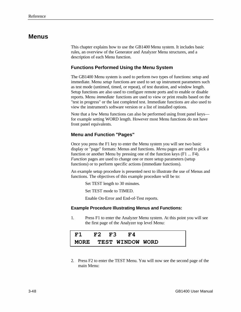
Reference
3-48 GB1400 User Manual
Menus
This chapter explains how to use the GB1400 Menu system. It includes basicrules, an overview of the Generator and Analyzer Menu structures, and adescription of each Menu function.
Functions Performed Using the Menu System
The GB1400 Menu system is used to perform two types of functions: setup andimmediate. Menu setup functions are used to set up instrument parameters suchas test mode (untimed, timed, or repeat), of test duration, and window length.Setup functions are also used to configure remote ports and to enable or disablereports. Menu immediate functions are used to view or print results based on the"test in progress" or the last completed test. Immediate functions are also used toview the instrument's software version or a list of installed options.
Note that a few Menu functions can also be performed using front panel keys—for example setting WORD length. However most Menu functions do not havefront panel equivalents.
Menu and Function "Pages"
Once you press the F1 key to enter the Menu system you will see two basicdisplay or "page" formats: Menus and functions. Menu pages are used to pick afunction or another Menu by pressing one of the function keys (F1 ... F4).Function pages are used to change one or more setup parameters (setupfunctions) or to perform specific actions (immediate functions).
An example setup procedure is presented next to illustrate the use of Menus andfunctions. The objectives of this example procedure will be to:
Set TEST length to 30 minutes.
Set TEST mode to TIMED.
Enable On-Error and End-of-Test reports.
Example Procedure Illustrating Menus and Functions:
1. Press F1 to enter the Analyzer Menu system. At this point you will seethe first page of the Analyzer top level Menu:
F1 F2 F3 F4 MORE TEST WINDOW WORD
2. Press F2 to enter the TEST Menu. You will now see the second page of themain Menu:
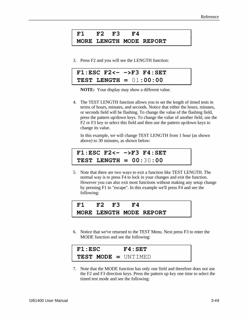
Reference
GB1400 User Manual 3-49
F1 F2 F3 F4 MORE LENGTH MODE REPORT
3. Press F2 and you will see the LENGTH function:
F1:ESC F2<- ->F3 F4:SET TEST LENGTH = 01:00:00
NOTE: Your display may show a different value.
4. The TEST LENGTH function allows you to set the length of timed tests interms of hours, minutes, and seconds. Notice that either the hours, minutes,or seconds field will be flashing. To change the value of the flashing field,press the pattern up/down keys. To change the value of another field, use theF2 or F3 key to select this field and then use the pattern up/down keys tochange its value.
In this example, we will change TEST LENGTH from 1 hour (as shownabove) to 30 minutes, as shown below:
F1:ESC F2<- ->F3 F4:SET TEST LENGTH = 00:30:00
5. Note that there are two ways to exit a function like TEST LENGTH. Thenormal way is to press F4 to lock in your changes and exit the function.However you can also exit most functions without making any setup changeby pressing F1 to "escape". In this example we'll press F4 and see thefollowing:
F1 F2 F3 F4 MORE LENGTH MODE REPORT
6. Notice that we've returned to the TEST Menu. Next press F3 to enter theMODE function and see the following:
F1:ESC F4:SET TEST MODE = UNTIMED
7. Note that the MODE function has only one field and therefore does not usethe F2 and F3 direction keys. Press the pattern up key one time to select thetimed test mode and see the following:
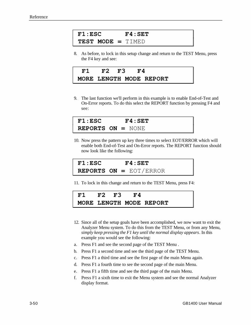
Reference
3-50 GB1400 User Manual
F1:ESC F4:SET TEST MODE = TIMED
8. As before, to lock in this setup change and return to the TEST Menu, pressthe F4 key and see:
F1 F2 F3 F4 MORE LENGTH MODE REPORT
9. The last function we'll perform in this example is to enable End-of-Test andOn-Error reports. To do this select the REPORT function by pressing F4 andsee:
F1:ESC F4:SET REPORTS ON = NONE
10. Now press the pattern up key three times to select EOT/ERROR which willenable both End-of-Test and On-Error reports. The REPORT function shouldnow look like the following:
F1:ESC F4:SET REPORTS ON = EOT/ERROR
11. To lock in this change and return to the TEST Menu, press F4:
F1 F2 F3 F4 MORE LENGTH MODE REPORT
12. Since all of the setup goals have been accomplished, we now want to exit theAnalyzer Menu system. To do this from the TEST Menu, or from any Menu,simply keep pressing the F1 key until the normal display appears. In thisexample you would see the following:
a. Press F1 and see the second page of the TEST Menu .
b. Press F1 a second time and see the third page of the TEST Menu.c. Press F1 a third time and see the first page of the main Menu again.
d. Press F1 a fourth time to see the second page of the main Menu.
e. Press F1 a fifth time and see the third page of the main Menu.f. Press F1 a sixth time to exit the Menu system and see the normal Analyzer
display format.

Reference
GB1400 User Manual 3-51
At this point you could perform a 30 minute timed test by:
1. Selecting the TEST display mode (press DISPLAY SELECT until a "T"appears in front of the BER field) and
2. Pressing the ERROR DETECTION CLEAR key to start a timed test interval.
General Rules for Using the Menu System
Operation of the GB1400 Analyzer and Generator Menu systems can be summedup by the following rules:
1. From the normal display mode, press F1 to enter the Menu system.
2. Navigate to a particular Menu function by pressing the appropriate "F" keysto select lower level Menus and finally the desired function.
3. In multi-field functions, use the F2 (move left) or F3 (move right) keys toselect a field. Note that the selected field is indicated by its flashing mode:flashing = selected, not flashing = not selected.
4. Once a field is selected, use the pattern up/down keys to increment ordecrement the value of the selected field.
5. To exit any setup function, press F4 to lock in all setup changes or F1 to"escape" without making any setup changes.
6. From any Menu, you can always exit the Menu system by pressing F1 keyone or more times until the normal display format appears.
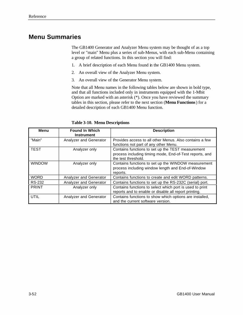
Reference
3-52 GB1400 User Manual
Menu Summaries
The GB1400 Generator and Analyzer Menu system may be thought of as a toplevel or "main" Menu plus a series of sub-Menus, with each sub-Menu containinga group of related functions. In this section you will find:
1. A brief description of each Menu found in the GB1400 Menu system.
2. An overall view of the Analyzer Menu system.
3. An overall view of the Generator Menu system.
Note that all Menu names in the following tables below are shown in bold type,and that all functions included only in instruments equipped with the 1-MbitOption are marked with an asterisk (*). Once you have reviewed the summarytables in this section, please refer to the next section (Menu Functions ) for adetailed description of each GB1400 Menu function.
Table 3-10. Menu Descriptions
Menu Found In WhichInstrument
Description
"Main" Analyzer and Generator Provides access to all other Menus. Also contains a fewfunctions not part of any other Menu.
TEST Analyzer only Contains functions to set up the TEST measurementprocess including timing mode, End-of-Test reports, andthe test threshold.
WINDOW Analyzer only Contains functions to set up the WINDOW measurementprocess including window length and End-of-Windowreports.
WORD Analyzer and Generator Contains functions to create and edit WORD patterns.RS-232 Analyzer and Generator Contains functions to set up the RS-232C (serial) port.PRINT Analyzer only Contains functions to select which port is used to print
reports and to enable or disable all report printing.UTIL Analyzer and Generator Contains functions to show which options are installed,
and the current software version.
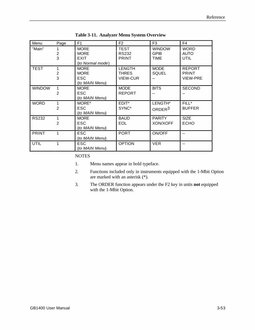
Reference
GB1400 User Manual 3-53
Table 3-11. Analyzer Menu System Overview
Menu Page F1 F2 F3 F4"Main" 1 MORE TEST WINDOW WORD
2 MORE RS232 GPIB AUTO3 EXIT
(to Normal mode)PRINT TIME UTIL
TEST 1 MORE LENGTH MODE REPORT2 MORE THRES SQUEL PRINT3 ESC
(to MAIN Menu)VIEW-CUR -- VIEW-PRE
WINDOW 1 MORE MODE BITS SECOND2 ESC
(to MAIN Menu)REPORT -- --
WORD 1 MORE* EDIT* LENGTH* FILL*2 ESC
(to MAIN Menu)SYNC* ORDER3 BUFFER
RS232 1 MORE BAUD PARITY SIZE2 ESC
(to MAIN Menu)EOL XON/XOFF ECHO
PRINT 1 ESC(to MAIN Menu)
PORT ON/OFF --
UTIL 1 ESC(to MAIN Menu)
OPTION VER --
NOTES
1. Menu names appear in bold typeface.
2. Functions included only in instruments equipped with the 1-Mbit Optionare marked with an asterisk (*).
3. The ORDER function appears under the F2 key in units not equippedwith the 1-Mbit Option.
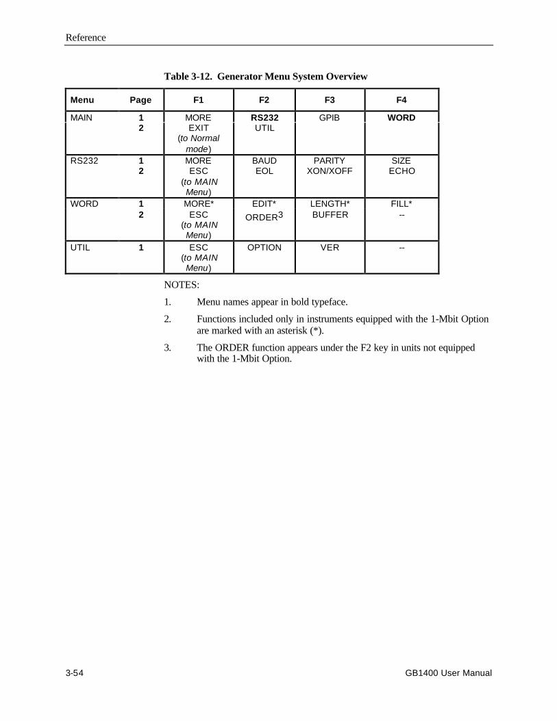
Reference
3-54 GB1400 User Manual
Table 3-12. Generator Menu System Overview
Menu Page F1 F2 F3 F4
MAIN 1 MORE RS232 GPIB WORD2 EXIT
(to Normalmode)
UTIL
RS232 1 MORE BAUD PARITY SIZE2 ESC
(to MAINMenu)
EOL XON/XOFF ECHO
WORD 1 MORE* EDIT* LENGTH* FILL*2 ESC
(to MAINMenu)
ORDER3 BUFFER --
UTIL 1 ESC(to MAINMenu)
OPTION VER --
NOTES:
1. Menu names appear in bold typeface.
2. Functions included only in instruments equipped with the 1-Mbit Optionare marked with an asterisk (*).
3. The ORDER function appears under the F2 key in units not equippedwith the 1-Mbit Option.
Reference
GB1400 User Manual 3-55
Menu Function Definitions
This section describes each Menu function included in the GB1400 Menusystem. For each function you will find the following information:
• Basic display format
• Menu in which it is located
• Function name used in the Menu system
• Whether it is found in the Analyzer, Generator, or both
• Which option(s) must be installed for this function to be available
• What this function is used for
• Parameters set using this function and their ranges
• Notes
Note that most of the following function descriptions are identified by a Menuname and a function name, for example Test Length. This is to clarify theapplication of the described function, and to differentiate functions that have thesame name, for example Word Mode and Window Mode. Also note that functiondescriptions are grouped by Menu.

Reference
3-56 GB1400 User Manual
Word Edit (EDIT)
Format: F1:ESC F2<- ->F3 F4:SET WORD AT ddddd = bbbbbbbb
Menu: WORD
Function Name: EDIT
Instruments: Analyzer and Generator
Options: Requires the 1-Mbit Option.
Application: Use this function to create new WORD patterns or edit the currentWORD pattern.
Parameters: Byte Location (ddddd): Set this parameter to the location (in decimal)of the byte you want to edit in the current WORD. May be set in therange: 00001 to M+1, where M the number of whole bytes in thecurrent WORD. If WORD length is M bytes plus N bits, then the"byte" location of the last N bits is M+1.
Byte Value (bbbbbbbb): This is the binary representation of theselected byte. Edit this byte using the front panel "bit" keys, MSB 1... LSB 8.
Range: 00000000 to 11111111 (binary)
Notes: Use the WORD LENGTH function to set WORD length.
See an additional list of remote commands in the Appendix thatsupport the 1-Mbit Programmable Word option.
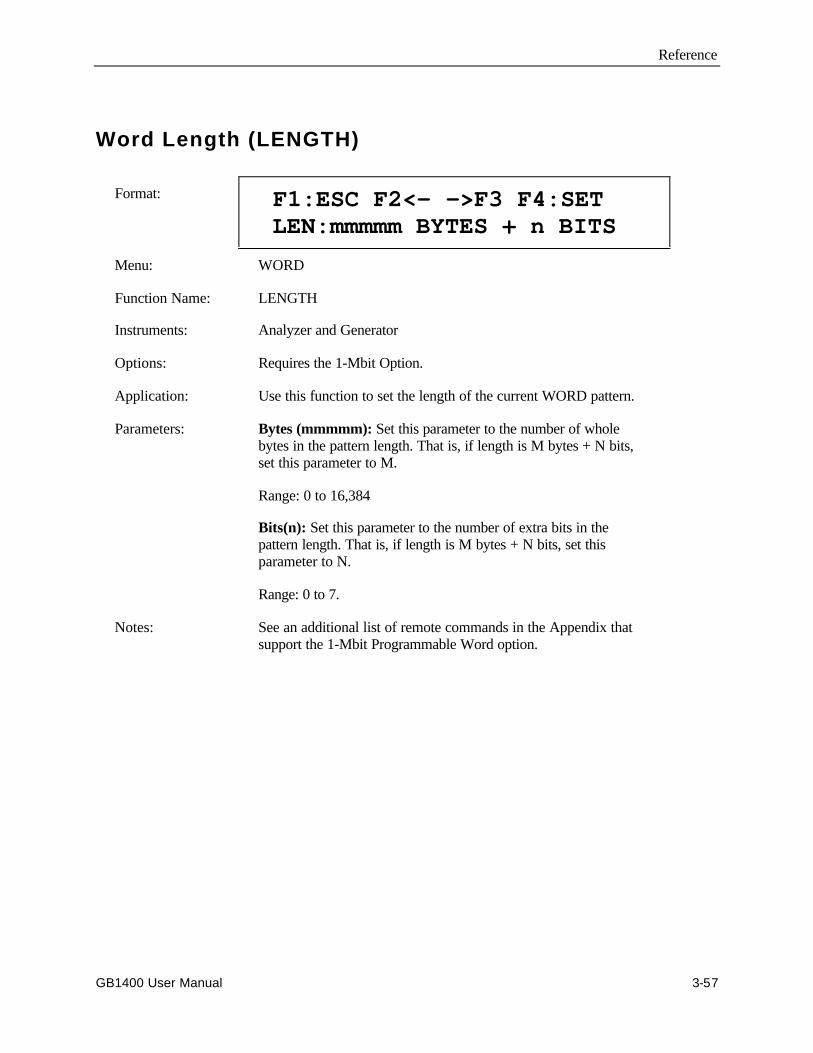
Reference
GB1400 User Manual 3-57
Word Length (LENGTH)
Format: F1:ESC F2<- ->F3 F4:SET LEN:mmmmm BYTES + n BITS
Menu: WORD
Function Name: LENGTH
Instruments: Analyzer and Generator
Options: Requires the 1-Mbit Option.
Application: Use this function to set the length of the current WORD pattern.
Parameters: Bytes (mmmmm): Set this parameter to the number of wholebytes in the pattern length. That is, if length is M bytes + N bits,set this parameter to M.
Range: 0 to 16,384
Bits(n): Set this parameter to the number of extra bits in thepattern length. That is, if length is M bytes + N bits, set thisparameter to N.
Range: 0 to 7.
Notes: See an additional list of remote commands in the Appendix thatsupport the 1-Mbit Programmable Word option.

Reference
3-58 GB1400 User Manual
Word Fill (FILL)
Format: F1:ESC F4:SET FILL WORD MEMORY WITH:hh
Menu: WORD
Function Name: FILL
Instruments: Analyzer and Generator
Options: Requires the 1-Mbit Option.
Application: Use this function to fill all bytes in the current WORD with thesame 8-bit pattern.
Parameters: Fill Byte (hh): Enter the hex value for the fill byte Range: 00 toFF.
Notes: You may use the fill function as the basis for a new WORDpattern, then edit individual bytes using the WORD EDITfunction to create the exact pattern that you need.
See an additional list of remote commands in the Appendix thatsupport the 1-Mbit Programmable Word option.
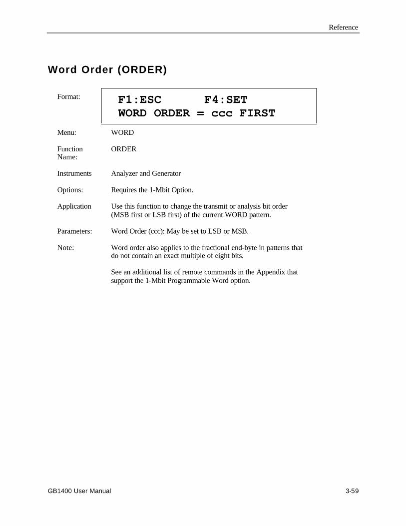
Reference
GB1400 User Manual 3-59
Word Order (ORDER)
Format: F1:ESC F4:SET WORD ORDER = ccc FIRST
Menu: WORD
FunctionName:
ORDER
Instruments Analyzer and Generator
Options: Requires the 1-Mbit Option.
Application Use this function to change the transmit or analysis bit order(MSB first or LSB first) of the current WORD pattern.
Parameters: Word Order (ccc): May be set to LSB or MSB.
Note: Word order also applies to the fractional end-byte in patterns thatdo not contain an exact multiple of eight bits.
See an additional list of remote commands in the Appendix thatsupport the 1-Mbit Programmable Word option.

Reference
3-60 GB1400 User Manual
Word Synchronization Threshold (SYNC)
Format: F1:ESC F4:SET WORD SYNC THRES LEVEL= d
Menu: WORD
Function Name: SYNC
Instruments: Analyzer only
Options: Requires the 1-Mbit Option.
Application: This function is used to set the BER synchronization threshold usedby the Analyzer for long WORD patterns. This function does notaffect the sync. thresholds for PRBS or short WORD patterns,which are fixed.
Parameters: Long Word Synchronization Threshold Level (d): Set thisparameter to a level from 1 to 9.
Notes: The long WORD synchronization threshold is always set to 256errors in a rolling window of variable length. The length of thiswindow is automatically set by the Analyzer, based on the selectedthreshold level, so that the nine threshold levels effectivelycorrespond to the following bit error rates:
Level BER
1 3.1 E-02 2 7.8 E-03 3 1.9 E-04 4 9.7E-04 5 4.8 E-04 6 2.4 E-04 7 1.2 E-04 8 6.1 E-05 9 3.0 E-05
See an additional list of remote commands in the Appendix thatsupport the 1-Mbit Programmable Word option.
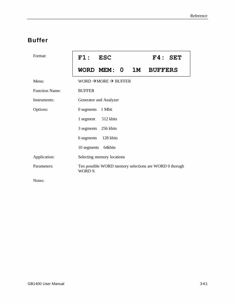
Reference
GB1400 User Manual 3-61
Buffer
Format: F1: ESC F4: SET
WORD MEM: 0 1M BUFFERS
Menu: WORD àMORE à BUFFER
Function Name: BUFFER
Instruments: Generator and Analyzer
Options: 0 segments 1 Mbit
1 segment 512 kbits
3 segments 256 kbits
6 segments 128 kbits
10 segments 64kbits
Application: Selecting memory locations
Parameters: Ten possible WORD memory selections are WORD 0 thorughWORD 9.
Notes:
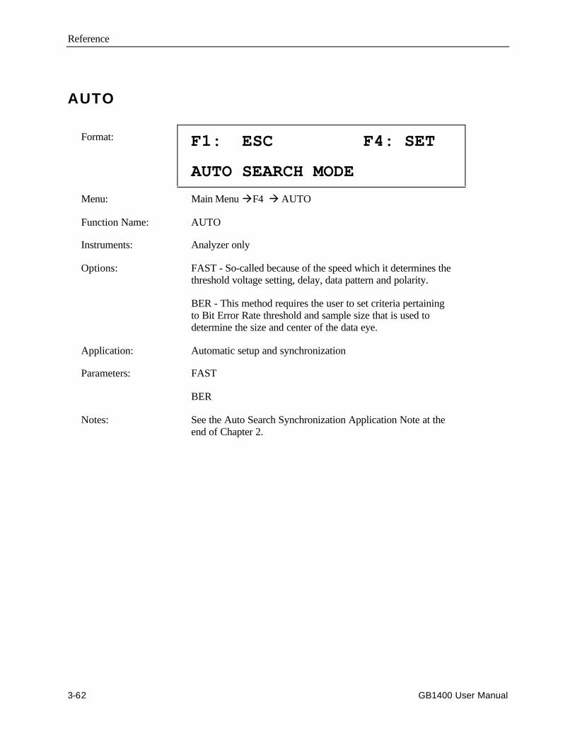
Reference
3-62 GB1400 User Manual
AUTO
Format: F1: ESC F4: SET
AUTO SEARCH MODE
Menu: Main Menu àF4 à AUTO
Function Name: AUTO
Instruments: Analyzer only
Options: FAST - So-called because of the speed which it determines thethreshold voltage setting, delay, data pattern and polarity.
BER - This method requires the user to set criteria pertainingto Bit Error Rate threshold and sample size that is used todetermine the size and center of the data eye.
Application: Automatic setup and synchronization
Parameters: FAST
BER
Notes: See the Auto Search Synchronization Application Note at theend of Chapter 2.

Reference
GB1400 User Manual 3-63
Test Length (LENGTH)
Format: F1:ESC F2<- ->F3 F4:SET TEST LENGTH = hh:mm:ss
Menu: TEST
Function Name: LENGTH
Instruments: Analyzer only
Options: None required. This is a standard feature.
Application: Use this function to set the duration of timed tests and therepeat interval of repeat timed tests.
Parameters: Hours (hh): Set from 00 to 23.Minutes (mm): Set from 00 to 59.Seconds (ss): Set from 00 to 59.
Notes: Test length does not affect untimed TEST intervals, or theTOTALIZE or WINDOW measurement processes.

Reference
3-64 GB1400 User Manual
Test Mode (MODE)
Format: F1:ESC F4:SET TEST MODE = ccccccc
Menu: TEST
Function Name: MODE
Instruments: Analyzer only
Options: None required. This is a standard feature.
Application: Use this function to select a test timing mode.
Parameters: Test Timing Mode (ccccccc): May be set to TIMED,REPEAT, or UNTIMED
Notes: This function applies only to the TEST measurement processand has no impact on either the TOTALIZE or WINDOWmeasurement processes.
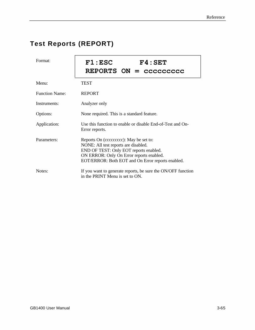
Reference
GB1400 User Manual 3-65
Test Reports (REPORT)
Format: F1:ESC F4:SET REPORTS ON = ccccccccc
Menu: TEST
Function Name: REPORT
Instruments: Analyzer only
Options: None required. This is a standard feature.
Application: Use this function to enable or disable End-of-Test and On-Error reports.
Parameters: Reports On (ccccccccc): May be set to:NONE: All test reports are disabled.END OF TEST: Only EOT reports enabled.ON ERROR: Only On Error reports enabled.EOT/ERROR: Both EOT and On Error reports enabled.
Notes: If you want to generate reports, be sure the ON/OFF functionin the PRINT Menu is set to ON.
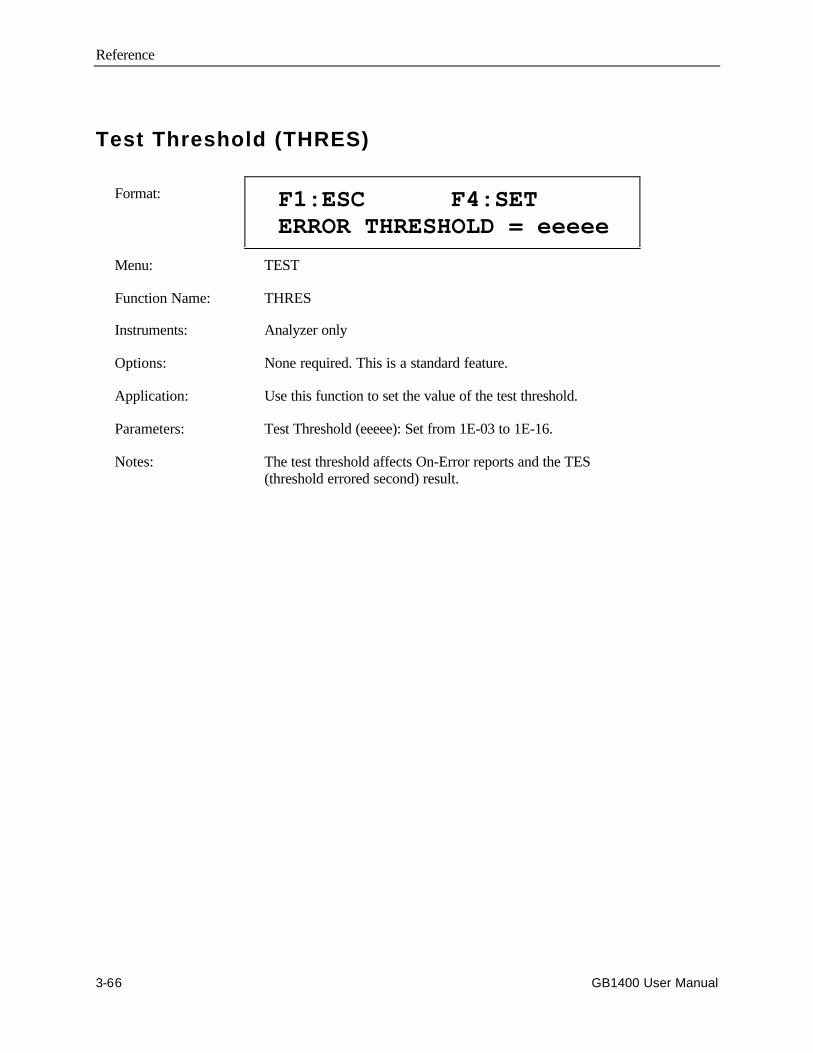
Reference
3-66 GB1400 User Manual
Test Threshold (THRES)
Format: F1:ESC F4:SET ERROR THRESHOLD = eeeee
Menu: TEST
Function Name: THRES
Instruments: Analyzer only
Options: None required. This is a standard feature.
Application: Use this function to set the value of the test threshold.
Parameters: Test Threshold (eeeee): Set from 1E-03 to 1E-16.
Notes: The test threshold affects On-Error reports and the TES(threshold errored second) result.

Reference
GB1400 User Manual 3-67
Test Squelch (SQUEL)
Format: F1:ESC F4:SET ON ERROR SQUELCH = ccc
Menu: TEST
Function Name: SQUEL
Instruments: Analyzer only
Options: None required. This is a standard feature.
Application: Use this function to enable or disable squelching of On-Errorreports.
Parameters: On Error Squelch (ccc): Set to ON or OFF
Notes: When On Error Squelch is ON, the analyzer will squelch(temporarily stop printing) On Error reports after tenconsecutive reports, that is ten consecutive seconds in whichBER exceeds the current test threshold. On Error reports willresume after 10 consecutive seconds in which the BER doesnot exceed the test threshold.
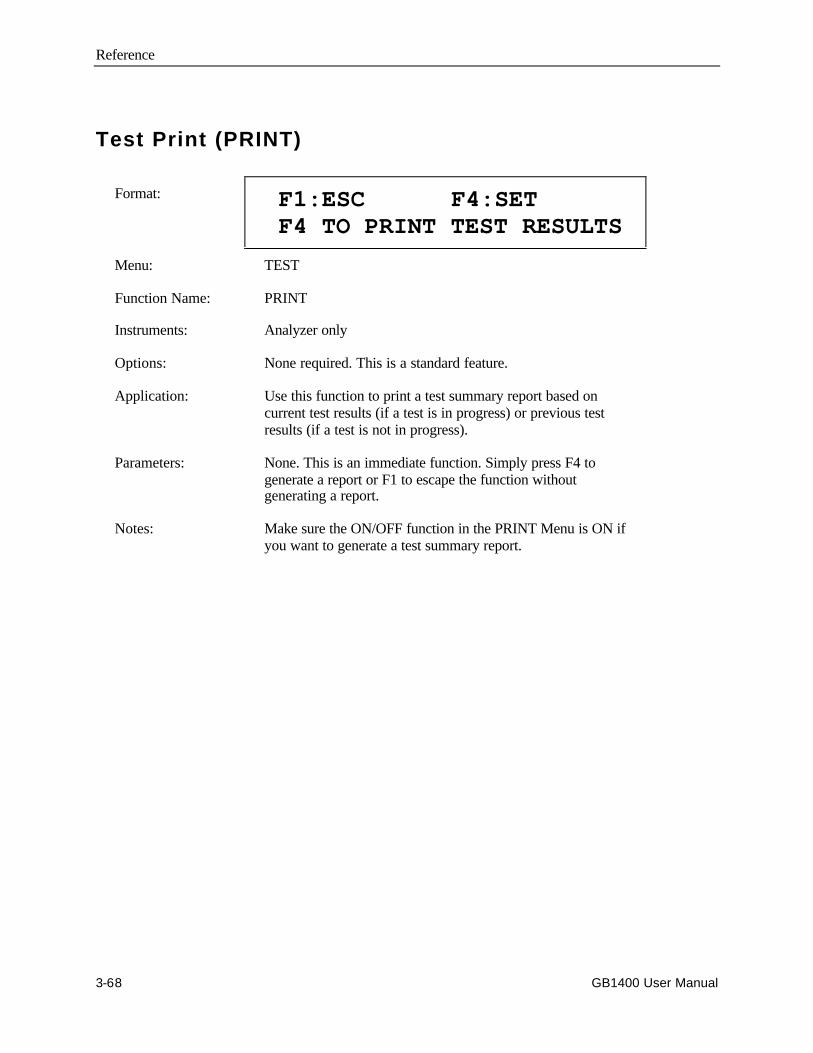
Reference
3-68 GB1400 User Manual
Test Print (PRINT)
Format: F1:ESC F4:SET F4 TO PRINT TEST RESULTS
Menu: TEST
Function Name: PRINT
Instruments: Analyzer only
Options: None required. This is a standard feature.
Application: Use this function to print a test summary report based oncurrent test results (if a test is in progress) or previous testresults (if a test is not in progress).
Parameters: None. This is an immediate function. Simply press F4 togenerate a report or F1 to escape the function withoutgenerating a report.
Notes: Make sure the ON/OFF function in the PRINT Menu is ON ifyou want to generate a test summary report.

Reference
GB1400 User Manual 3-69
Test View Previous (VIEW-PRE)
Format: F1:ESC F4:SET (result name)(count) (%)
Menu: TEST
Function Name: VIEW-PRE
Instruments: Analyzer only
Options: None required. This is a standard feature.
Application: Use this function to view results from the last completed test.
Parameters: This is an immediate function. After selecting VIEW-PREuse the pattern up/down keys to scroll through the resultsshown below.
START (test start time), STOP (test stop time), ELAPSED(duration of test), TTL BIT (total number of bits in interval),TTL ERR (total number of bit errors counted), AVE ERRORRATE (BER of TEST interval), CUR ERROR RATE (BERof WINDOW interval), US (Unavailable Seconds), SES(Severely Errored Seconds), TES (Threshold ErroredSeconds), ES (Errored Seconds), EFS (Error Free Seconds),DM (Degraded Minutes), SIG LOSS SEC (seconds in whicha loss of signal has occurred), SYNC LOSS SEC (seconds inwhich a loss of pattern synchronization has occurred),PHASE ERR SEC (seconds in which a phase error hasoccurred).
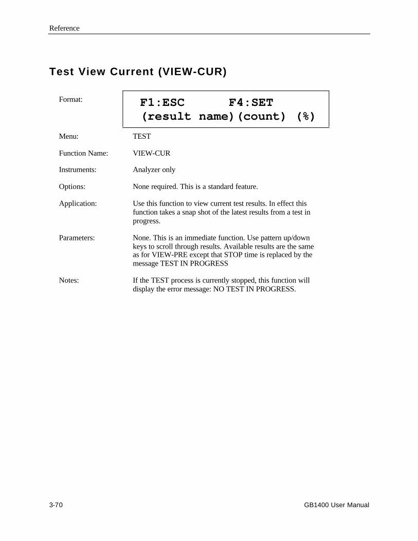
Reference
3-70 GB1400 User Manual
Test View Current (VIEW-CUR)
Format: F1:ESC F4:SET (result name)(count) (%)
Menu: TEST
Function Name: VIEW-CUR
Instruments: Analyzer only
Options: None required. This is a standard feature.
Application: Use this function to view current test results. In effect thisfunction takes a snap shot of the latest results from a test inprogress.
Parameters: None. This is an immediate function. Use pattern up/downkeys to scroll through results. Available results are the sameas for VIEW-PRE except that STOP time is replaced by themessage TEST IN PROGRESS
Notes: If the TEST process is currently stopped, this function willdisplay the error message: NO TEST IN PROGRESS.
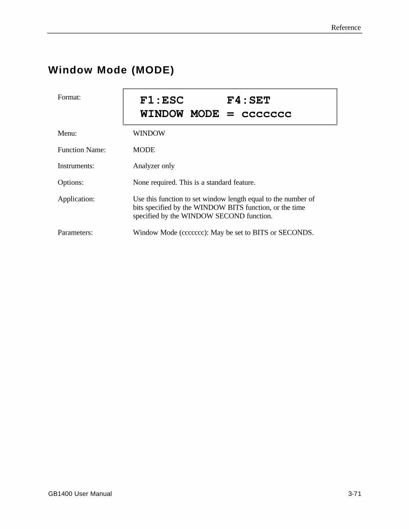
Reference
GB1400 User Manual 3-71
Window Mode (MODE)
Format: F1:ESC F4:SET WINDOW MODE = ccccccc
Menu: WINDOW
Function Name: MODE
Instruments: Analyzer only
Options: None required. This is a standard feature.
Application: Use this function to set window length equal to the number ofbits specified by the WINDOW BITS function, or the timespecified by the WINDOW SECOND function.
Parameters: Window Mode (ccccccc): May be set to BITS or SECONDS.

Reference
3-72 GB1400 User Manual
Window Interval in Bits (BITS)
Format: F1:ESC F4:SET WINDOW LEN = 1.0eEE BITS
Menu: WINDOW
Function Name: BITS
Instruments: Analyzer only
Options: None required. This is a standard feature.
Application: When WINDOW MODE is set to BITS, use this function to setwindow duration in terms of bits.
Parameters: Window Length (EE): May be set from 1.0e08 to 1.0e16
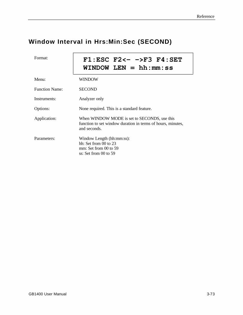
Reference
GB1400 User Manual 3-73
Window Interval in Hrs:Min:Sec (SECOND)
Format: F1:ESC F2<- ->F3 F4:SET WINDOW LEN = hh:mm:ss
Menu: WINDOW
Function Name: SECOND
Instruments: Analyzer only
Options: None required. This is a standard feature.
Application: When WINDOW MODE is set to SECONDS, use thisfunction to set window duration in terms of hours, minutes,and seconds.
Parameters: Window Length (hh:mm:ss):hh: Set from 00 to 23mm: Set from 00 to 59ss: Set from 00 to 59
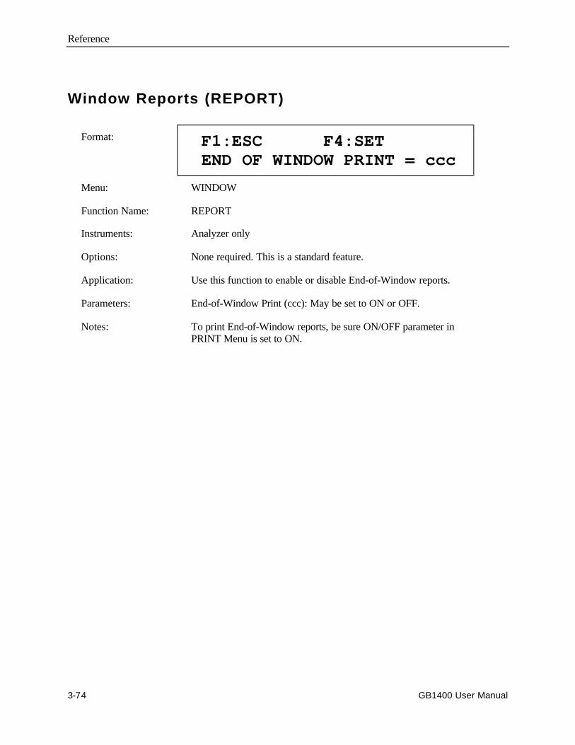
Reference
3-74 GB1400 User Manual
Window Reports (REPORT)
Format: F1:ESC F4:SET END OF WINDOW PRINT = ccc
Menu: WINDOW
Function Name: REPORT
Instruments: Analyzer only
Options: None required. This is a standard feature.
Application: Use this function to enable or disable End-of-Window reports.
Parameters: End-of-Window Print (ccc): May be set to ON or OFF.
Notes: To print End-of-Window reports, be sure ON/OFF parameter inPRINT Menu is set to ON.
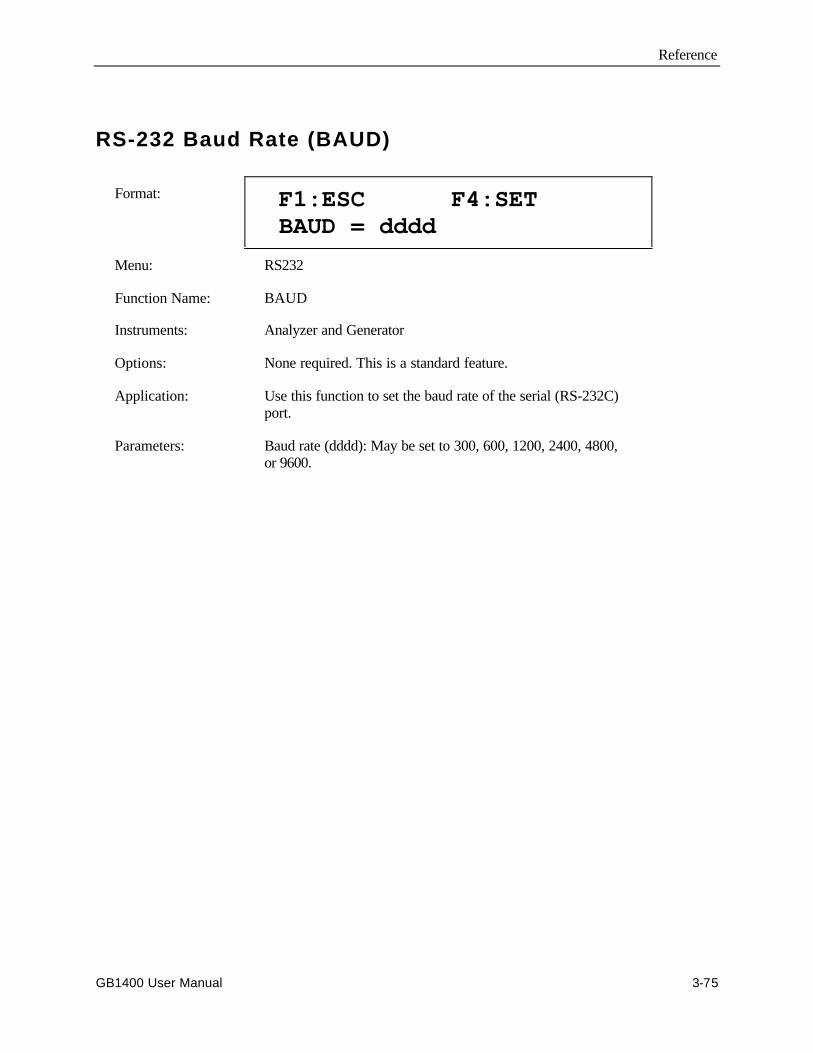
Reference
GB1400 User Manual 3-75
RS-232 Baud Rate (BAUD)
Format: F1:ESC F4:SET BAUD = dddd
Menu: RS232
Function Name: BAUD
Instruments: Analyzer and Generator
Options: None required. This is a standard feature.
Application: Use this function to set the baud rate of the serial (RS-232C)port.
Parameters: Baud rate (dddd): May be set to 300, 600, 1200, 2400, 4800,or 9600.
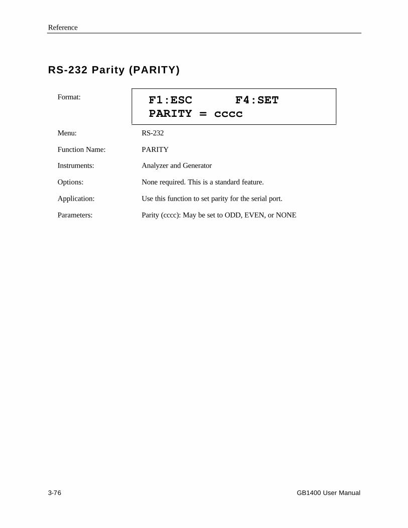
Reference
3-76 GB1400 User Manual
RS-232 Parity (PARITY)
Format: F1:ESC F4:SET PARITY = cccc
Menu: RS-232
Function Name: PARITY
Instruments: Analyzer and Generator
Options: None required. This is a standard feature.
Application: Use this function to set parity for the serial port.
Parameters: Parity (cccc): May be set to ODD, EVEN, or NONE
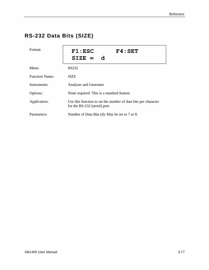
Reference
GB1400 User Manual 3-77
RS-232 Data Bits (SIZE)
Format: F1:ESC F4:SET SIZE = d
Menu: RS232
Function Name: SIZE
Instruments: Analyzer and Generator
Options: None required. This is a standard feature.
Application: Use this function to set the number of data bits per characterfor the RS-232 (serial) port.
Parameters: Number of Data Bits (d): May be set to 7 or 8.
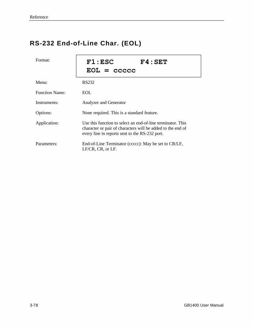
Reference
3-78 GB1400 User Manual
RS-232 End-of-Line Char. (EOL)
Format: F1:ESC F4:SET EOL = ccccc
Menu: RS232
Function Name: EOL
Instruments: Analyzer and Generator
Options: None required. This is a standard feature.
Application: Use this function to select an end-of-line terminator. Thischaracter or pair of characters will be added to the end ofevery line in reports sent to the RS-232 port.
Parameters: End-of-Line Terminator (ccccc): May be set to CR/LF,LF/CR, CR, or LF.
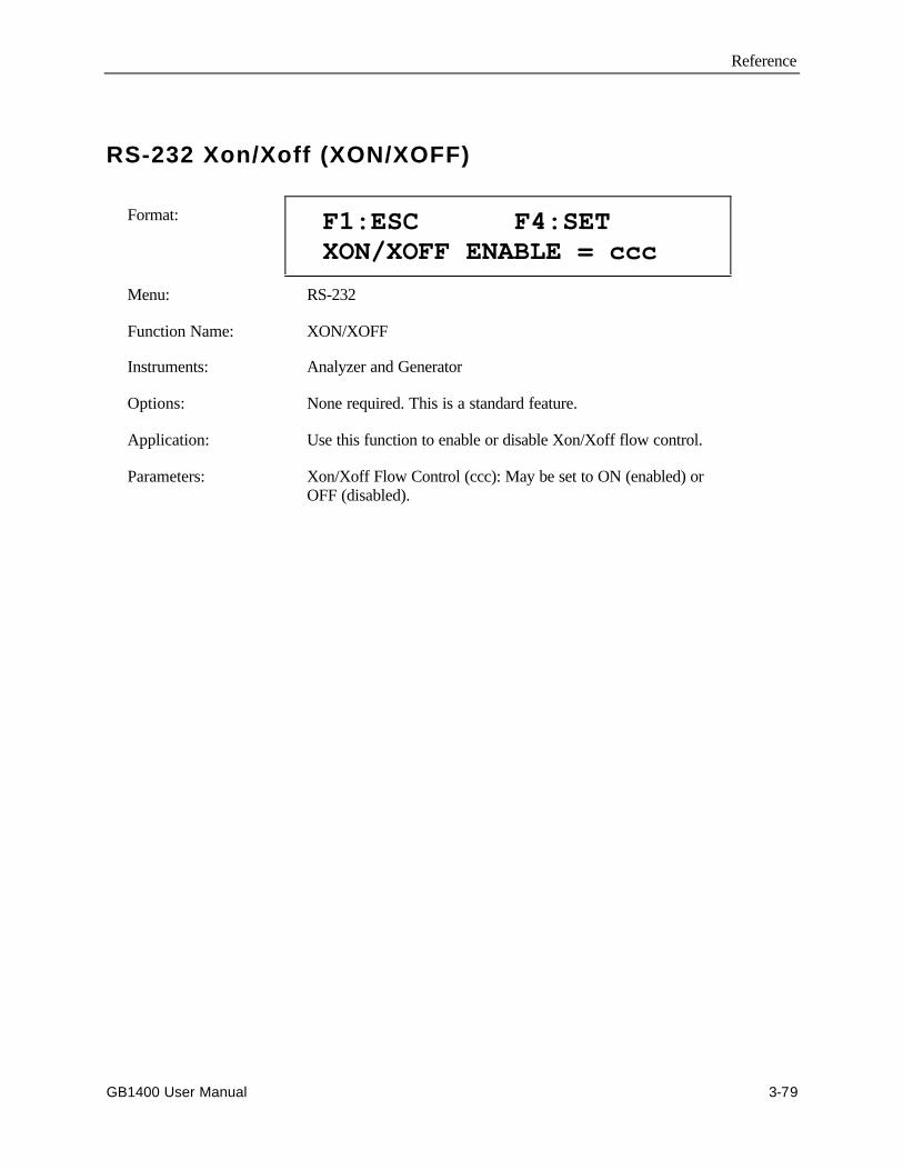
Reference
GB1400 User Manual 3-79
RS-232 Xon/Xoff (XON/XOFF)
Format: F1:ESC F4:SET XON/XOFF ENABLE = ccc
Menu: RS-232
Function Name: XON/XOFF
Instruments: Analyzer and Generator
Options: None required. This is a standard feature.
Application: Use this function to enable or disable Xon/Xoff flow control.
Parameters: Xon/Xoff Flow Control (ccc): May be set to ON (enabled) orOFF (disabled).
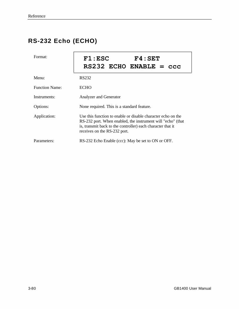
Reference
3-80 GB1400 User Manual
RS-232 Echo (ECHO)
Format: F1:ESC F4:SET RS232 ECHO ENABLE = ccc
Menu: RS232
Function Name: ECHO
Instruments: Analyzer and Generator
Options: None required. This is a standard feature.
Application: Use this function to enable or disable character echo on theRS-232 port. When enabled, the instrument will "echo" (thatis, transmit back to the controller) each character that itreceives on the RS-232 port.
Parameters: RS-232 Echo Enable (ccc): May be set to ON or OFF.

Reference
GB1400 User Manual 3-81
GPIB
Format: F1:ESC F4:SET TERMINATOR = cccccc
Menu: Selected from "main" Menu.
Function Name: GPIB
Instruments: Analyzer and Generator
Options: None required. This is a standard feature.
Application: Use to select the GPIB end-of-line termination character orcharacters.
Parameters: GPIB End-of-Line Terminator (cccccc): May be set to EOI orEOI/LF.
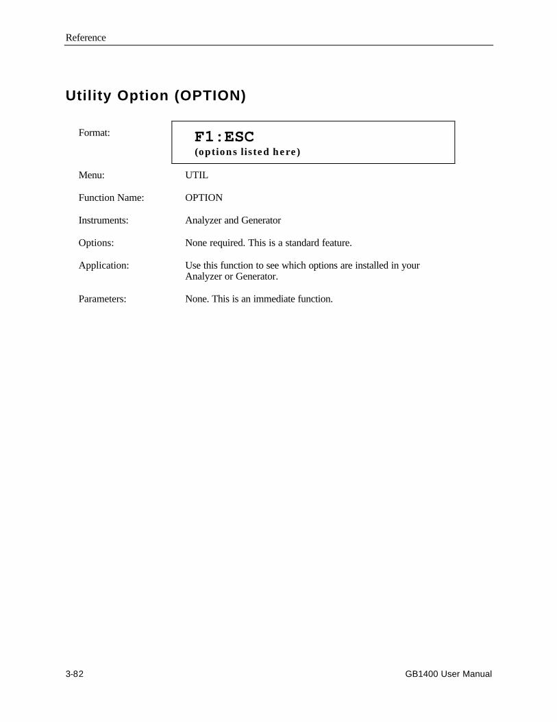
Reference
3-82 GB1400 User Manual
Utility Option (OPTION)
Format: F1:ESC (options listed here)
Menu: UTIL
Function Name: OPTION
Instruments: Analyzer and Generator
Options: None required. This is a standard feature.
Application: Use this function to see which options are installed in yourAnalyzer or Generator.
Parameters: None. This is an immediate function.
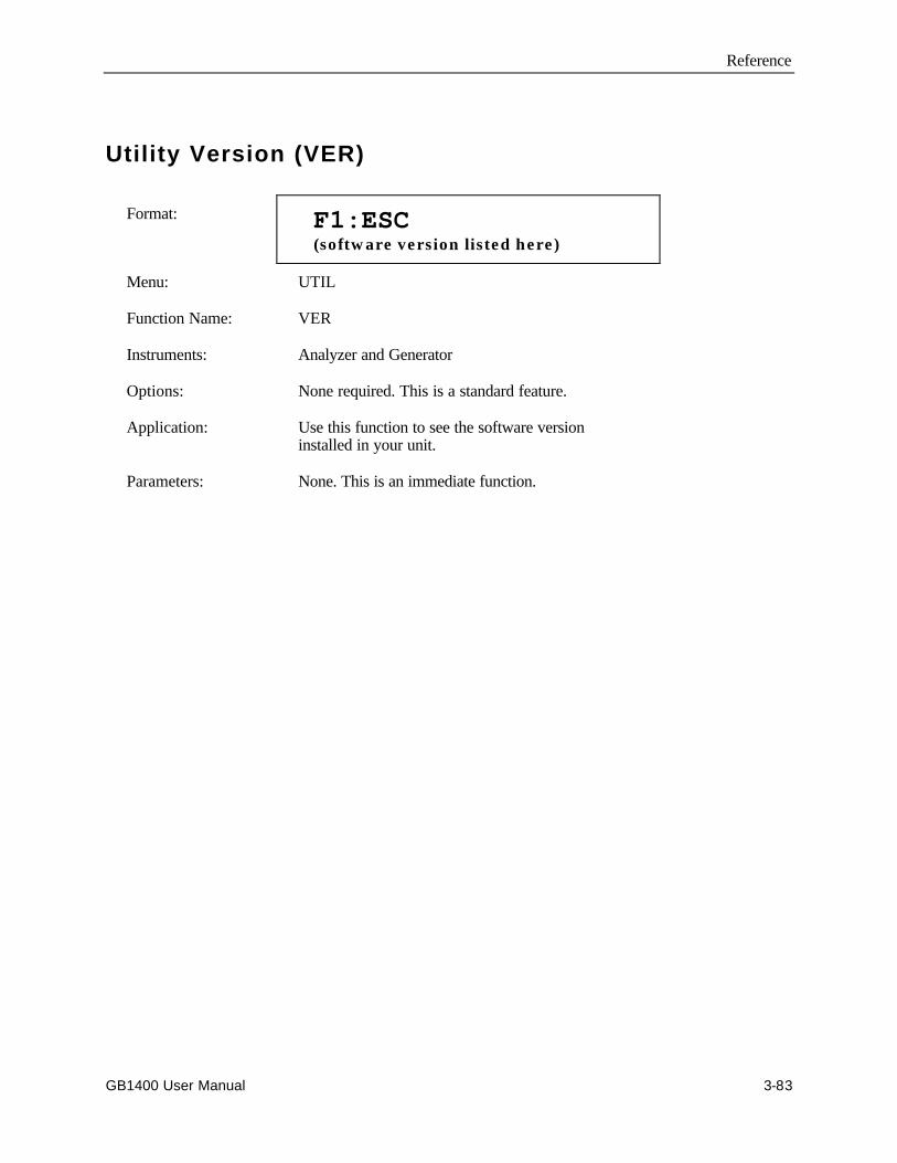
Reference
GB1400 User Manual 3-83
Utility Version (VER)
Format: F1:ESC (software version listed here)
Menu: UTIL
Function Name: VER
Instruments: Analyzer and Generator
Options: None required. This is a standard feature.
Application: Use this function to see the software versioninstalled in your unit.
Parameters: None. This is an immediate function.
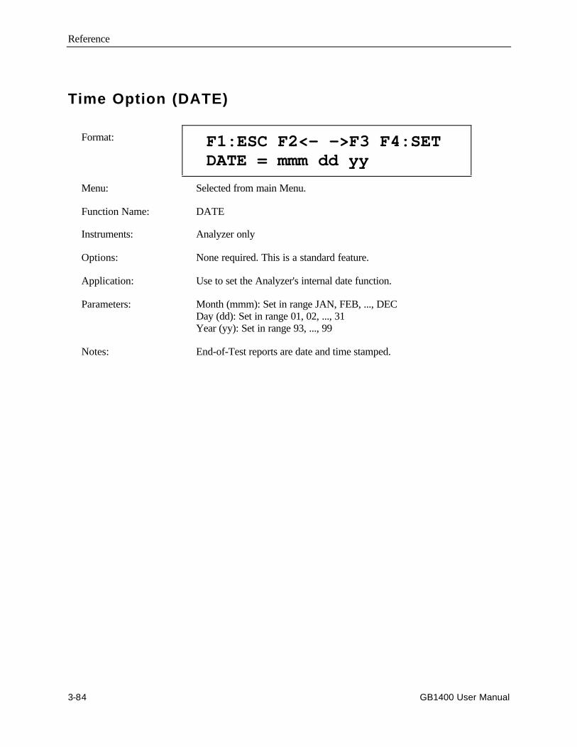
Reference
3-84 GB1400 User Manual
Time Option (DATE)
Format: F1:ESC F2<- ->F3 F4:SET DATE = mmm dd yy
Menu: Selected from main Menu.
Function Name: DATE
Instruments: Analyzer only
Options: None required. This is a standard feature.
Application: Use to set the Analyzer's internal date function.
Parameters: Month (mmm): Set in range JAN, FEB, ..., DECDay (dd): Set in range 01, 02, ..., 31Year (yy): Set in range 93, ..., 99
Notes: End-of-Test reports are date and time stamped.
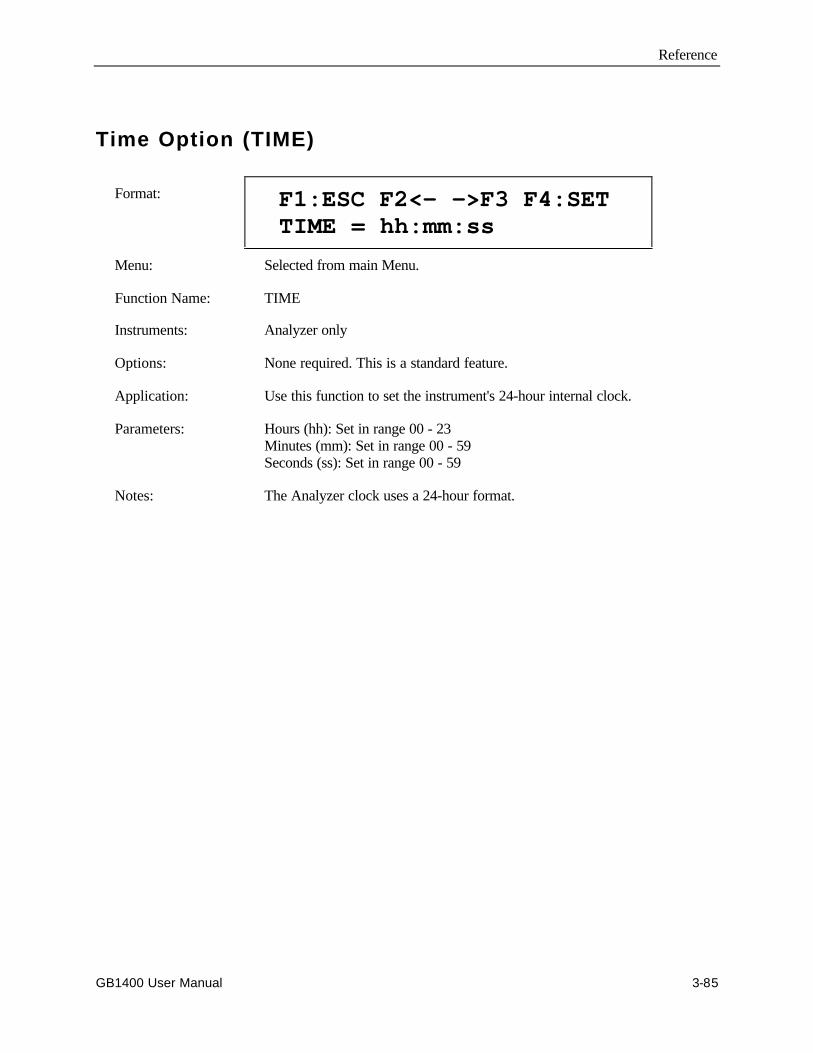
Reference
GB1400 User Manual 3-85
Time Option (TIME)
Format: F1:ESC F2<- ->F3 F4:SET TIME = hh:mm:ss
Menu: Selected from main Menu.
Function Name: TIME
Instruments: Analyzer only
Options: None required. This is a standard feature.
Application: Use this function to set the instrument's 24-hour internal clock.
Parameters: Hours (hh): Set in range 00 - 23Minutes (mm): Set in range 00 - 59Seconds (ss): Set in range 00 - 59
Notes: The Analyzer clock uses a 24-hour format.

Reference
3-86 GB1400 User Manual

Appendices
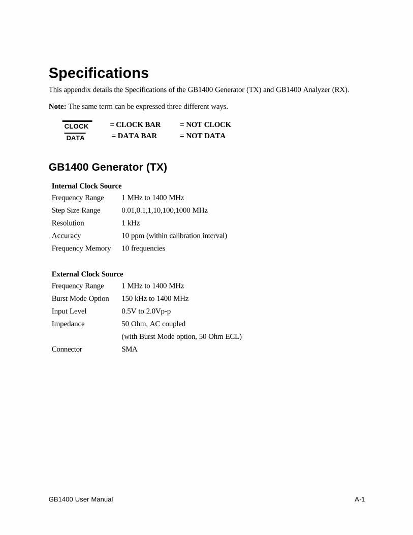
GB1400 User Manual A-1
SpecificationsThis appendix details the Specifications of the GB1400 Generator (TX) and GB1400 Analyzer (RX).
Note: The same term can be expressed three different ways.
CLOCK = CLOCK BAR = NOT CLOCK
DATA = DATA BAR = NOT DATA
GB1400 Generator (TX)
Internal Clock Source
Frequency Range 1 MHz to 1400 MHz
Step Size Range 0.01,0.1,1,10,100,1000 MHz
Resolution 1 kHz
Accuracy 10 ppm (within calibration interval)
Frequency Memory 10 frequencies
External Clock Source
Frequency Range 1 MHz to 1400 MHz
Burst Mode Option 150 kHz to 1400 MHz
Input Level 0.5V to 2.0Vp-p
Impedance 50 Ohm, AC coupled
(with Burst Mode option, 50 Ohm ECL)
Connector SMA

Specifications
A-2 GB1400 User Manual
Data Patterns
Format NRZ-L, Normal and Complement
Type PRBS or WORD (User-programmable)
PRBS Patterns 2n-1; n=7,15,17,20,23
WORD Lengths 8 and 16-bit only,
1 Mbit memory (with optional memory)
PRBS Phase Tap Information
The Pseudo-Random data patterns used in the GB1400 TX are generated by shift-register andexclusive-OR feedback technique. The pattern is dependent on which feedback taps (shift registeroutputs) are selected.
For example, PN7 is defined as a seven-stage shift register, which the output of stages 6 and 7 fedback (through an exclusive-OR gate) to the beginning of the shift register. The feedback taps usedin the GB1400 are tabulated here.
Pattern Feedback TapsPN7 6 7PN15 14 15PN17 14 17PN20 17 20PN23 18 23
Data Output (True and Complement)
Amplitude Variable 0.5V to 2.0V, 50 mV steps
Baseline Offset Variable -2.0V to +1.0V, 50 mV steps
-2.0V to +1.8V, 50 mV steps, with PECL option
Pulse Top Limit +2.0V into 50 Ohms, +4.0V open load+2.8V into 50 Ohms (with PECL option)
Rise/Fall Time 150 pS, typical (20-80%) at 1V amplitude
Source Impedance 50 Ohms
Output Timing CLOCK/DATA edge-aligned (+/- 100 pS)
Jitter: 100 pS, peak-to-peak Max. referenced to EXT clock
Connectors SMA
Data Inhibit Rear panel SMA, ECL (50 Ohms to -2V term)
Data Inhibit Rate Asynchronous, 1 bit and 500 pS minimum width
Data Invert Front Panel Selectable
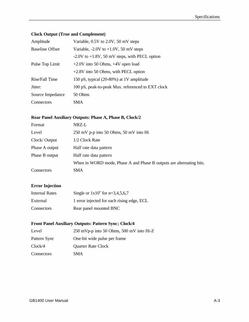
Specifications
GB1400 User Manual A-3
Clock Output (True and Complement)
Amplitude Variable, 0.5V to 2.0V, 50 mV steps
Baseline Offset Variable, -2.0V to +1.0V, 50 mV steps
-2.0V to +1.8V, 50 mV steps, with PECL option
Pulse Top Limit +2.0V into 50 Ohms, +4V open load
+2.8V into 50 Ohms, with PECL option
Rise/Fall Time 150 pS, typical (20-80%) at 1V amplitude
Jitter: 100 pS, peak-to-peak Max. referenced to EXT clock
Source Impedance 50 Ohms
Connectors SMA
Rear Panel Auxiliary Outputs: Phase A, Phase B, Clock/2
Format NRZ-L
Level 250 mV p-p into 50 Ohms, 50 mV into Hi
Clock/ Output 1/2 Clock Rate
Phase A output Half rate data pattern
Phase B output Half rate data pattern
When in WORD mode, Phase A and Phase B outputs are alternating bits.
Connectors SMA
Error Injection
Internal Rates Single or 1x10n for n=3,4,5,6,7
External 1 error injected for each rising edge, ECL
Connectors Rear panel mounted BNC
Front Panel Auxiliary Outputs: Pattern Sync; Clock/4
Level 250 mVp-p into 50 Ohms, 500 mV into Hi-Z
Pattern Sync One-bit wide pulse per frame
Clock/4 Quarter Rate Clock
Connectors SMA
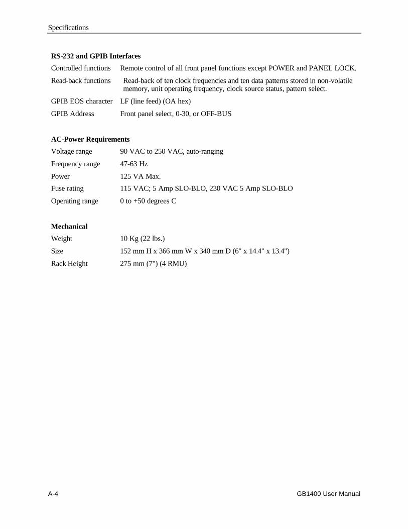
Specifications
A-4 GB1400 User Manual
RS-232 and GPIB Interfaces
Controlled functions Remote control of all front panel functions except POWER and PANEL LOCK.
Read-back functions Read-back of ten clock frequencies and ten data patterns stored in non-volatilememory, unit operating frequency, clock source status, pattern select.
GPIB EOS character LF (line feed) (OA hex)
GPIB Address Front panel select, 0-30, or OFF-BUS
AC-Power Requirements
Voltage range 90 VAC to 250 VAC, auto-ranging
Frequency range 47-63 Hz
Power 125 VA Max.
Fuse rating 115 VAC; 5 Amp SLO-BLO, 230 VAC 5 Amp SLO-BLO
Operating range 0 to +50 degrees C
Mechanical
Weight 10 Kg (22 lbs.)
Size 152 mm H x 366 mm W x 340 mm D (6" x 14.4" x 13.4")
Rack Height 275 mm (7") (4 RMU)
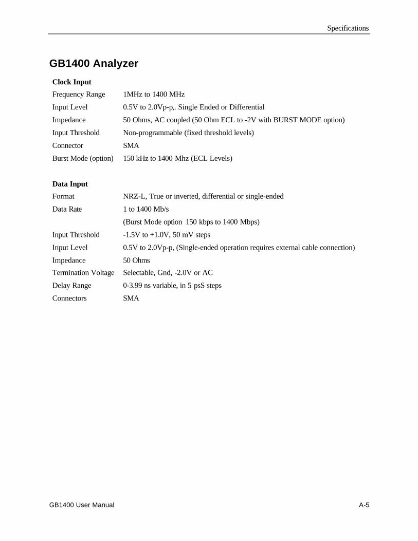
Specifications
GB1400 User Manual A-5
GB1400 Analyzer
Clock Input
Frequency Range 1MHz to 1400 MHz
Input Level 0.5V to 2.0Vp-p,. Single Ended or Differential
Impedance 50 Ohms, AC coupled (50 Ohm ECL to -2V with BURST MODE option)
Input Threshold Non-programmable (fixed threshold levels)
Connector SMA
Burst Mode (option) 150 kHz to 1400 Mhz (ECL Levels)
Data Input
Format NRZ-L, True or inverted, differential or single-ended
Data Rate 1 to 1400 Mb/s
(Burst Mode option 150 kbps to 1400 Mbps)
Input Threshold -1.5V to +1.0V, 50 mV steps
Input Level 0.5V to 2.0Vp-p, (Single-ended operation requires external cable connection)
Impedance 50 Ohms
Termination Voltage Selectable, Gnd, -2.0V or AC
Delay Range 0-3.99 ns variable, in 5 psS steps
Connectors SMA
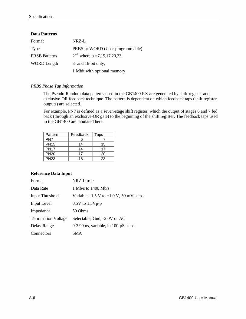
Specifications
A-6 GB1400 User Manual
Data Patterns
Format NRZ-L
Type PRBS or WORD (User-programmable)
PRSB Patterns 2n-1 where n =7,15,17,20,23
WORD Length 8- and 16-bit only,
1 Mbit with optional memory
PRBS Phase Tap Information
The Pseudo-Random data patterns used in the GB1400 RX are generated by shift-register andexclusive-OR feedback technique. The pattern is dependent on which feedback taps (shift registeroutputs) are selected.
For example, PN7 is defined as a seven-stage shift register, which the output of stages 6 and 7 fedback (through an exclusive-OR gate) to the beginning of the shift register. The feedback taps usedin the GB1400 are tabulated here.
Pattern Feedback TapsPN7 6 7PN15 14 15PN17 14 17PN20 17 20PN23 18 23
Reference Data Input
Format NRZ-L true
Data Rate 1 Mb/s to 1400 Mb/s
Input Threshold Variable, -1.5 V to +1.0 V, 50 mV steps
Input Level 0.5V to 1.5Vp-p
Impedance 50 Ohms
Termination Voltage Selectable, Gnd, -2.0V or AC
Delay Range 0-3.90 ns, variable, in 100 pS steps
Connectors SMA
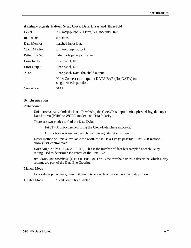
Specifications
GB1400 User Manual A-7
Auxiliary Signals: Pattern Sync, Clock, Data, Error and Threshold
Level 250 mVp-p into 50 Ohms, 500 mV into Hi-Z
Impedance 50 Ohms
Data Monitor Latched Input Data
Clock Monitor Buffered Input Clock
Pattern SYNC 1-bit wide pulse per frame
Error Inhibit Rear panel, ECL
Error Output Rear panel, ECL
AUX Rear panel, Data Threshold output
Note: Connect this output to DATA BAR (Not DATA) forsingle-ended operation.
Connectors SMA
Synchronization
Auto Search
Unit automatically finds the Data Threshold , the Clock/Data input timing phase delay, the inputData Pattern (PRBS or WORD mode), and Data Polarity.
There are two modes to find the Data Delay
FAST - A quick method using the Clock/Data phase indicator.
BER - A slower method which uses the signal's bit error rate.
Either method will make available the width of the Data Eye (if possible). The BER methodallows user control over:
Data Sample Size (10E-4 to 10E-11). This is the number of data bits sampled at each Delaysetting used to determine the center of the Data Eye.
Bit Error Rate Threshold (10E-3 to 10E-10). This is the threshold used to determine which Delaysettings are part of the Data Eye Crossing.
Manual Mode
User selects parameters, then unit attempts to synchronize on the input data pattern.
Disable Mode SYNC circuitry disabled
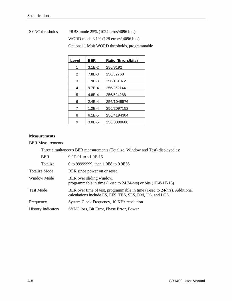
Specifications
A-8 GB1400 User Manual
SYNC thresholds PRBS mode 25% (1024 erros/4096 bits)
WORD mode 3.1% (128 errors/ 4096 bits)
Optional 1 Mbit WORD thresholds, programmable
Level BER Ratio (Errors/bits)
1 3.1E-2 256/8192
2 7.8E-3 256/32768
3 1.9E-3 256/131072
4 9.7E-4 256/262144
5 4.8E-4 256/524288
6 2.4E-4 256/1048576
7 1.2E-4 256/2097152
8 6.1E-5 256/4194304
9 3.0E-5 256/8388608
Measurements
BER Measurements
Three simultaneous BER measurements (Totalize, Window and Test) displayed as:
BER 9.9E-01 to <1.0E-16
Totalize 0 to 99999999, then 1.0E8 to 9.9E36
Totalize Mode BER since power on or reset
Window Mode BER over sliding window,programmable in time (1-sec to 24 24-hrs) or bits (1E-8-1E-16)
Test Mode BER over time of test, programmable in time (1-sec to 24-hrs). Additionalcalculations include ES, EFS, TES, SES, DM, US, and LOS.
Frequency System Clock Frequency, 10 KHz resolution
History Indicators SYNC loss, Bit Error, Phase Error, Power

Specifications
GB1400 User Manual A-9
RS-232 and GPIB Interfaces
Controlled functions Remote control of all front panel functions except POWER and PANEL LOCK.
Read-back functions Read-back of ten data patterns stored in non-volatile memory - unit operatingfrequency, bit error rate information, sync and history status, pattern select.
GPIB EOS character LF (line feed) (OA hex)
GPIB Address Front panel select, 0-30, or OFF-BUS
Printer Interface
Format Parallel Centronics-type and re-directable to serial (RS-232C) or GPIB ports.
Hardcopy Front panel key, prints unit setup
Print on event Print if BER threshold is exceeded; programmable rate (1E-02 to 1E-16)
Print on EOW Print on End of Window,programmable in time (1 sec - 24 hrs), or bits (1E8-1E16)
Print on EOT Print on End of Test, programmable rate 1 sec to 24 hours
AC-Power Requirements
Voltage range 90 VAC to 250 VAC, auto-ranging
Frequency range 47-63 Hz
Power 125 VA Max.
Fuse rating 115 VAC; 4 Amp, 230 VAC 2 Amp
Operating range 0 to +50 degrees C
Mechanical
Weight 10 Kg (22 lbs.)
Size 152 mm H x 366 mm W x 340 mm D (6" x 14.4" x 13.4")
Rack Height 275 mm (7") (4 RMU)

Specifications
A-10 GB1400 User Manual
GB1400 User Manual B-1
BERT Primer/ Technical Articles
Section Table of Contents• BERT Primer, see page B-2
Technical Articles
• BERT - First and last measurement tool for transmission device designacceptability, see page B-13
• Ensure Accuracy of Bit Error Rate Tests, see page B-21
• Measure Error Rates Quickly and Accurately, see page B-32
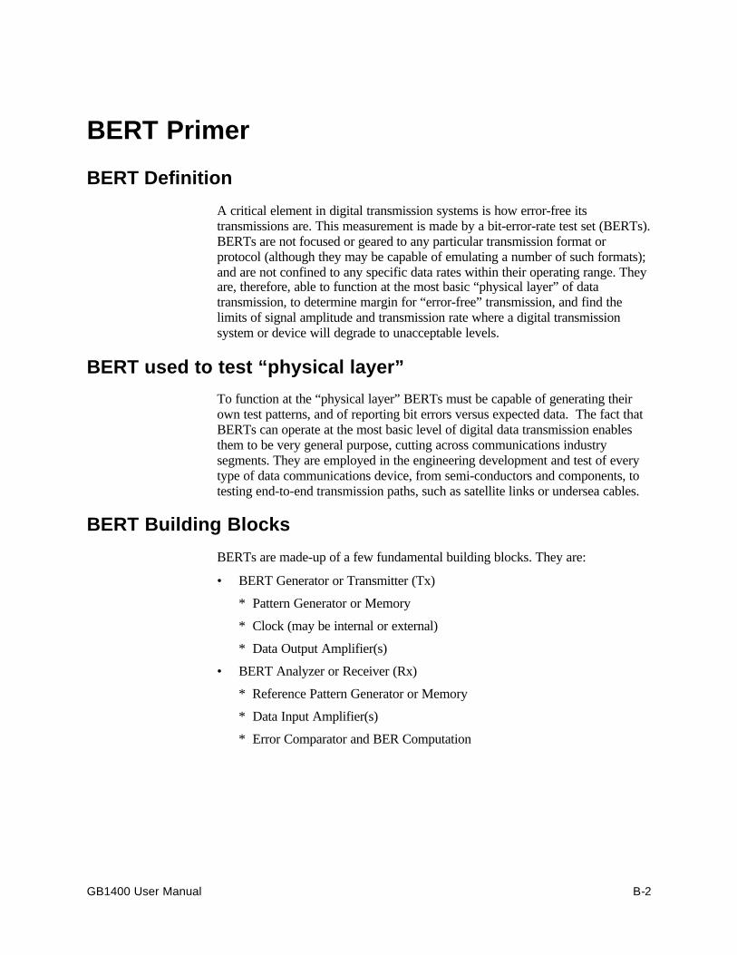
GB1400 User Manual B-2
BERT Primer
BERT Definition
A critical element in digital transmission systems is how error-free itstransmissions are. This measurement is made by a bit-error-rate test set (BERTs).BERTs are not focused or geared to any particular transmission format orprotocol (although they may be capable of emulating a number of such formats);and are not confined to any specific data rates within their operating range. Theyare, therefore, able to function at the most basic “physical layer” of datatransmission, to determine margin for “error-free” transmission, and find thelimits of signal amplitude and transmission rate where a digital transmissionsystem or device will degrade to unacceptable levels.
BERT used to test “physical layer”
To function at the “physical layer” BERTs must be capable of generating theirown test patterns, and of reporting bit errors versus expected data. The fact thatBERTs can operate at the most basic level of digital data transmission enablesthem to be very general purpose, cutting across communications industrysegments. They are employed in the engineering development and test of everytype of data communications device, from semi-conductors and components, totesting end-to-end transmission paths, such as satellite links or undersea cables.
BERT Building Blocks
BERTs are made-up of a few fundamental building blocks. They are:
• BERT Generator or Transmitter (Tx)
* Pattern Generator or Memory
* Clock (may be internal or external)
* Data Output Amplifier(s)
• BERT Analyzer or Receiver (Rx)
* Reference Pattern Generator or Memory
* Data Input Amplifier(s)
* Error Comparator and BER Computation

BERT Primer
GB1400 User Manual B-3
BERT Pattern Generation
Almost all BERT generators include some type of pseudo-random patternsgeneration. These “PRBS” patterns are used to stimulate a “Device Under Test”(DUT) for the purpose of comparing actual received data with the “reference”data available to the receiver. These PRBS patterns are described below.
PRBS Patterns
A type of data pattern used by most BERTs is called “PRBS” - pseudo-randombinary sequence. PRBS patterns are categorized by the bit-length of the binaryword generating the pattern. For example, a seven-bit PRBS will be output as aserial stream consisting of 27 -1 (2 to the 7th power minus 1 which equals 127bits). These 127 bits include all possible permutations of seven bits with theexception of “0000000”. Due to the nature of the Shift Register used to generatethese codes, the code 0000000 never appears. Hence the PRBS pattern is alwaysof the form “2n - 1”, e.g., 215 - 1, 223- 1.
ITU Specifications (CCITT O.150 and O.151) identify several types of PRBSpatterns used for communications testing. These patterns are usually generatedby hardware shift registers with appropriate feedback. If the shift register has n-stages, the maximum pattern length will be 2^n - 1.
If the digital signal is taken directly from the output of the shift register (non-inverted signal), the longest string of consecutive ZERO's will equal n-1. If thesignal is inverted, n consecutive ZERO's will be produced.
Table 1 of ITU Specification O.150 lists several different types of PRBS testpatterns. Some of the recommended test patterns use "non-inverted" signals(PRBS 9, 11, 23), some use "inverted" signals (PRBS 15), and some use both the"non-inverted" and the "inverted" signals (PRBS 20).

BERT Primer
B-4 GB1400 User Manual
The Tektronix PB200 provides capabilities to invert data on both transmit andreceive. This provides full flexibility to adjust the PRBS signal to the user'sexact requirements. Table B-1 identifies the PB200 polynomial and shift registerfeedback taps used to generate PRBS data.
Table B-1 - PRBS Polynomials and shift register feedback taps for PB200
N Menu Label PRBSPattern
PrimitivePolynomial
Feedback Taps Length in bits (2N-1 bits)
7 PN 7 27-1 x7 + x + 1 6 and 7 127
9 PN 9 29-1 x9 + x4 + 1 5 and 9 511
10 PN 10 210-1 x10 + x3 + 1 7 and 10 1023
11 PN 11 211-1 x11 + x2 + 1 9 and 11 2047
15 PN 15 215-1 x15 + x + 1 14 and 15 32,767
23 PN 23 223-1 x23 + x5 + 1 18 and 23 8,388,607
31 PN 31 231-1 x31 + x3 + 1 28 and 31 2,147,483,647
The Tektronix GB700/1400 provides capabilities to invert data on both transmitand receive. This provides full flexibility to adjust the PRBS signal to the user'sexact requirements. Table B-2 identifies the GB700/1400 polynomial and shiftregister feedback taps used to generate PRBS data.
Table B-2 - PRBS Polynomials and shift register feedback taps forGB700/GB1400
N Menu Label PRBSPattern
PrimitivePolynomial
Feedback Taps Length in bits (2N-1 bits)
7 PN 7 27-1 x7 + x + 1 6 and 7 127
15 PN 15 215-1 x15 + x + 1 14 and 15 32,767
17 PN 17 217-1 x17 + x3 + 1 14 and 17 131,071
20 PN 20 220-1 X20 + x3 + 1 17 and 20 1,048,575
23 PN 23 223-1 x23 + x5 + 1 18 and 23 8,388,607
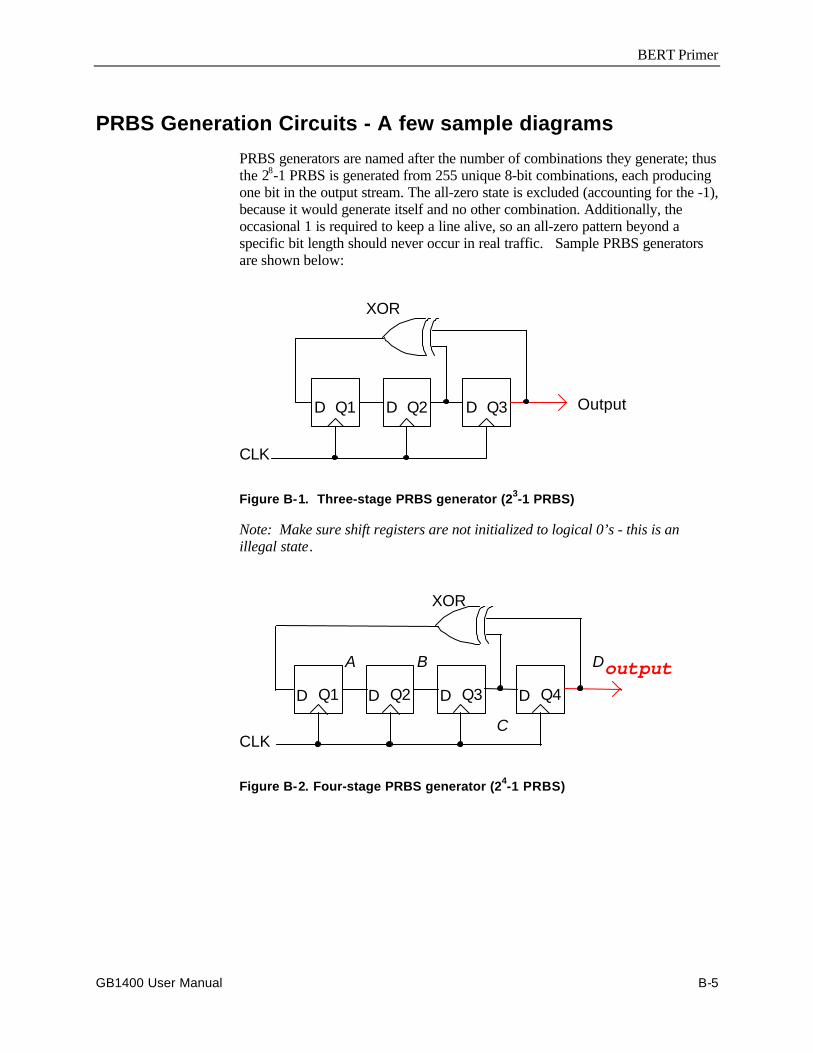
BERT Primer
GB1400 User Manual B-5
PRBS Generation Circuits - A few sample diagrams
PRBS generators are named after the number of combinations they generate; thusthe 28-1 PRBS is generated from 255 unique 8-bit combinations, each producingone bit in the output stream. The all-zero state is excluded (accounting for the -1),because it would generate itself and no other combination. Additionally, theoccasional 1 is required to keep a line alive, so an all-zero pattern beyond aspecific bit length should never occur in real traffic. Sample PRBS generatorsare shown below:
D Q1 D Q2 D Q3
CLK
Output
XOR
Figure B-1. Three-stage PRBS generator (23-1 PRBS)
Note: Make sure shift registers are not initialized to logical 0’s - this is anillegal state.
D Q3 D Q4
CLK
outputD Q2D Q1
XOR
A B
C
D
Figure B-2. Four-stage PRBS generator (24-1 PRBS)
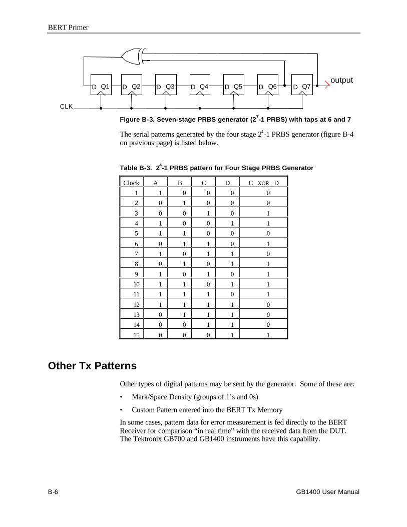
BERT Primer
B-6 GB1400 User Manual
CLK
D Q1 D Q2 D Q3output
D Q4 D Q5 D Q6 D Q7
Figure B-3. Seven-stage PRBS generator (27-1 PRBS) with taps at 6 and 7
The serial patterns generated by the four stage 24-1 PRBS generator (figure B-4on previous page) is listed below.
Table B-3. 24-1 PRBS pattern for Four Stage PRBS Generator
Clock A B C D C XOR D
1 1 0 0 0 0
2 0 1 0 0 0
3 0 0 1 0 1
4 1 0 0 1 1
5 1 1 0 0 0
6 0 1 1 0 1
7 1 0 1 1 0
8 0 1 0 1 1
9 1 0 1 0 1
10 1 1 0 1 1
11 1 1 1 0 1
12 1 1 1 1 0
13 0 1 1 1 0
14 0 0 1 1 0
15 0 0 0 1 1
Other Tx Patterns
Other types of digital patterns may be sent by the generator. Some of these are:
• Mark/Space Density (groups of 1’s and 0s)
• Custom Pattern entered into the BERT Tx Memory
In some cases, pattern data for error measurement is fed directly to the BERTReceiver for comparison “in real time” with the received data from the DUT.The Tektronix GB700 and GB1400 instruments have this capability.
BERT Primer
GB1400 User Manual B-7
BERT Clock
A clock source is necessary to provide the timing for generation of the BERTdigital output, and to provide the logic strobe for acquisition of the data by thereceiver. The Clock must provide clean, sharp logic transitions and needs to bedelayable to account for time the signals from the BERT take to propagatethrough the DUT. Most BERTs have an internal clock source. All BERTs havethe ability to operate using an External Clock. Some BERTs have the ability toderive the internal clock using an External Reference signal at a fixed frequency,usually 10 MHz, as a basis for increased stability and frequency accuracy.Providing External Clock allows the possibility of modulating clock frequency(adding jitter) in order to stress ability of clock recovery circuit in DUT towithstand conditions of noise and pulse dispersion typically found in datatransmission systems and circuits.
Output Amplifiers
BERT Output Amplifiers are responsible for providing features such asamplitude offset, peak-to-peak levels, impedances and the degree to which thesemay be set and varied for the purpose of accommodating the DUT, or testingsensitivity levels of the DUT. These amplifiers also determine or limit theavailability of single-ended or differential output. The typical electrical I/O onour BERTs is a 1-volt signal centered around ground, either Differential orSingle-Ended. Differential outputs provide an inverted “copy” of the outputsignal and are used to drive complimentary inputs. If a single-ended signal isneeded, the complimentary output should always be terminated to the appropriateload to insure best signal quality.
Data Coding, NRZ
Data generated by a BERT is defined according to certain standard voltagelevels, amplitude swings and transitions which the BERT Receiver willunderstand as representing a logical “1” or “0”. The most common type ofencoding is “NRZ” (non-return to zero). For NRZ encoding, consecutive 1’s, forexample, cause the output level to hold at the “true” state, rather than changingbetween consecutive bits. The level for NRZ only changes when there is atransition from 1 to 0, or 0 to 1. Other coding schemes are: RZ (return to zero),CMI, AMI... and many others. Coding schemes may be optimized to make iteasier to recover clock at the far end, or to attempt to keep voltage levelsbalanced on twisted pair conductors.
BERT Receiver or "Error Analyzer" Components
For testing using PRBS, the BERT Analyzer relies on its own internal PRBSgenerator to provide a standard for comparison with the incoming bit stream fromthe device under test. Transmitters and receivers must be set to the same clockspeed and pattern length.
BERT Primer
B-8 GB1400 User Manual
Received Data Pattern Reference
If the transmitter is using some other known standard pattern, such as a particularMark-Space Density pattern, a copy of that pattern must also be generated by thereceiver. The BER reference data may be a User Defined pattern. The samepattern used by the transmitter must be loaded into the analyzer's memory.Finally, an application specific data stream, supplied at the customer site, may befed directly to the BERT Receiver as an external Reference Data source. Not allBERTs have this feature, but our GB700 and GB1400 both do.
Data Input Amplifier(s)
The BERT input amplifier stage must accommodate a range of data signalamplitudes, DC offsets and input termination impedances. Most BERTs willhandle either single ended or differential signals and provide a 50-Ohmtermination. Some BERTs, including our GB700 and GB1400, offer either 50 or75 Ohm input impedance. BERTs typically do not have a great deal of input gainto accommodate small signals, as oscilloscopes or spectrum analyzers do. Mostof our BERTs require 500 mV signal amplitude for minimum data input levels.
Error Comparator
The BERT receiver compares the incoming data stream bit-by-bit with itsinternal pattern using an Exclusive OR gate (XOR) and responds to non-matching inputs by sending a “1” to a built-in error counter. The number oferrors compared with the number of bits received determines the BER, or Bit-Error Rate. This is usually expressed as a power of 10 using a negativeexponent, since the fraction of errored bits to total bits must be 1 or less.
BER Computation
Ideally, the BER will be smaller than 10-9 (one errored bit in one billion). A rateof 10-6 is considered marginal. The size of the counter registers used to counttotal bits and errored bits determines the range of BER which the BERT canmeasure. The limits will be in terms of how large a BER can be measured (i.e.,how “bad” the error rate is), as well as how small (how “good”).
Other BER Measurements
BER measurements may be expressed in various ways: Simple errored bit rate,the ratio of errored to total bits, is usually stated in scientific notation using anegative power of ten exponent. Other BER statistics include: Total Errored Bitsand Total Bits, Errored Seconds (the number of seconds which contained at leastone bit error), Error-Free Seconds, and other definitions. Many of these arespecified and defined in BellCore and ITU Test Procedures, and other standards.
BERT Primer
GB1400 User Manual B-9
Confidence Level in BER Measurement
At first glance, one might think that the BER is known after receiving just one biterror. It would be expressed as 1 over the total number of bits received. But howdo we know what the “true” BER is? After all, the first errored bit could havebeen just a freak “glitch”. In reality, from a statistical confidence point of view,we must measure long enough to get many errors. This could take a very longtime.
Confidence Requires Collecting Many Errors
If the transmission system had a true BER of 10-12, and we were running at 100Mb/s, the average time between errors would be 10,000 seconds. At 3600seconds in an hour, the average time between errors would be nearly 3 hours!We need more than just one “error event” to have any confidence at all in statingan “error rate”. Also, the more errors we accumulate, the greater our confidencelevel that the BER measurement is truly representative of the device under test.
For a Poisson distribution of errors , BER accuracy is 1 over the square root ofthe number of errors. An accuracy of 5% requires 400 errors to have beencounted. Conversely, for 95% confidence that an error rate is less than somelimit, the DUT must be error free for three times the reciprocal of that limit. Forexample, to assure an error rate less than 10 per hour, the test must run error freefor 0.3 hours.
Additional Reading
Dr. Dan Wolaver has written an excellent article on confidence levels in BERmeasurements titled: “Measure Error Rates Quickly and Accurately".
The article appears later in this section on BERT Technology/ Technical Articles.
Stress Testing
Test times can be dramatically reduced in BER measurement by stressing thedevice under test to increase errors. This is done by either:
* Adding Attenuation* Adding Jitter* Adding Noise
Attenuation degrades S/N (signal-to-noise) ratio, and thus reduces the size of thedata “eye” in amplitude. Adding jitter on the clock (modulating the clock period,causing the clock edge to jump around) effectively reduces the data “eye” inwidth. A third technique is to add noise, which also degrades S/N. Any ofthese methods will increase the BER in a known way which allows extrapolationof what the error rate would be without stress. Measuring BER in the presence ofadded stress is an essential technique in testing high quality (very low error rate)systems quickly.
BERT Primer
B-10 GB1400 User Manual
Other BERT Features
In addition to measuring Bit Error Rate, BERTs may have additional featureswhich enhance ease of use or expand test capabilities. Some of these might be:
* Eye Width Measurement
* Auto Synch Feature
* Pattern Locking Methods
* Pattern Loading Software
* Error Insertion
* Internal Jitter Generation
Eye Width Measurement
Since the BERT Receiver must have the ability to delay the received clock, itmay have the ability to run the clock edge through a range sufficient to cover thereceived data “eye” . The “eye” width is the time during which the received dataexhibits clean logic “1” or “0” levels. Ideally the “eye width” is one over the bitrate. At the edge of the “eye”, the signal is transitioning from one level to theother. The “Eye Width” for any Error Rate is a measure of a system’s timingand jitter tolerance. A designer might have to meet a spec such as “eye width at500Mb/s and 10-9 BER must be 1.0ns or greater”. The manufacturer is thenconfident that there is sufficient margin in his product to live up to his customers’expectations. Vertical compression of the eye (from ISI, echoes, regeneratoroutput variations, decision-level instability, etc.) from ideal can be used toextrapolate error rate, and derive minimum S/N ratios to assure specifiedperformance.
The user should run the test equipment back-to-back (i.e., Transmitter connecteddirectly to Receiver with no device in the test path) first, to establish maximumeye width. BERTs inherently have their own set-up and hold times, so back-to-back results will always be a little less than perfect.
Auto-Synch
Auto-Synch is the ability of the BERT Receiver to search in time and inamplitude level for the optimum place to put the Clock edge for the cleanest logiclevel information. This positioning must be done, whether automatically ormanually, before any meaningful BER measurement can be made. All of ourBERT products have this Auto-Synch feature.
BERT Primer
GB1400 User Manual B-11
Pattern Lock
Before a BER measurement can be made, the BERT Transmitter and Receivermust be using the same test pattern. This may be guaranteed if they use the samePRBS or fixed word pattern and are running at the same clock rate, but there isstill the issue of having the bit comparison begin at the same point in the pattern.All of our general purpose BERTs have the ability to do an “auto search” forpattern lock. There are two techniques commonly used for this: the “bit slip” or“clock slip” method, and the “feed forward” method.
In the “bit slip” method, each error detected causes a one-bit slip in the referencepattern, until the beginning of the pattern is reached. This is normally the onlymethod that can be used with custom data structures or word patterns. This is themethod the GB1400 uses to synchronize any data pattern. This is also themethod used for WORD patterns with the GB700 and GB1400 instruments.With the “bit slip” method, synchronization times will vary by the length of thepattern. The longer the pattern, the longer the sync time.
In the “feed forward” method, which works for PRBS patterns only, a certainnumber of arriving bits are latched into the Receivers PRBS shift register andused as the “seed” for the start of the PRBS generation. This is the method theGB700 and GB1400 use for PRBS synchronization.
Both methods rely on realizing some minimum acceptable BER before theReceiver considers it has obtained “pattern lock”. It will then beginaccumulating “bit errors” in the error counter register.
Pattern Loading Software
Almost all BERTs have the ability to accept loading of reference patterns intointernal memories in both transmitter and receiver. In many cases this is viacomputer interface, either RS-232 or GPIB. The GB1400 has an front panelfloppy disk drive to load patterns. The GB700 and GB1400 use either RS-232or GPIB.
Pattern creation software is a valuable aid in developing custom patterns. Asimple spread-sheet like tool is available for our BERT products to help with thisneed.
Error Insertion
Most BERTs have the ability to internally generate bit errors, either singly or atspecific bit error rates. This calls for altering bits in the output pattern which areopposite from the bits the receiver will use at that location, thus causing theReceiver to tally a bit error. This feature may be important in measuring abilityof device under test to withstand or recover from such errors. Some BERTs,including our GB700, will allow an external “trigger” signal to cause animmediate bit error to be output.
Error insertion is also a useful tool to test the “integrity” of your equipmentsetup. You should always insert a few errors in your setup to conform correctoperation before you start your data collection.

BERT Primer
B-12 GB1400 User Manual
Jitter Generation
Some BERTs have the ability to generate and impose jitter on the internal clock.A jittered External Clock input is the means for adding jitter to the Tx source onGB700 and GB1400 BERT instruments.

GB1400 User Manual B-13
Technical note
BERT - first and last measurement tool fortransmission device design acceptability
Bit error rate testers (BERTs) are the basic tool for testing the quality of transmission systemsand circuit elements. The job of the BERT is simple - to feed test patterns bit-by-bit through thetransmission path or device-under-test (DUT), and confirm that the error rate is sufficiently low.Typical acceptable error rates might be one in one billion bits or lower.
Under the hood, BERTs are all 1s and 0s. The general-purpose BERT, one that would be used indeveloping and testing serial transmission designs, independent of any communicationsprotocols, operates entirely on this level. You have control of the frequency (bits per second),pattern, output amplitude and timing, and can tweak these values to stress a system to determinethe margin conditions of "acceptable" operation, and reveal design weaknesses.
Some BERTs are also designed to test quality at the data link layer of a data transmissioninterface/electrical specification or protocol, beyond simply running at the correct operatingfrequencies and tolerances for the standard. These BERTs are able to recognize frames/packetsand generate them, emulating the data formats called for in the standards. They are useful whileprotocol standards are being hashed out. When a protocol becomes firm and established, theBERT is replaced by the Protocol Analyzer.
The Tektronix family of BERT products (listed at the end of this article, along with specificfunctionality) all conform to the above description, but differ from each other in frequency range,number of channels, and pattern and format generation capability.
Bit error rate testingA BERT's basic measurement is the bit error rate (BER), defined as the number of bit errors overthe total number of bits sent. This is a small, positive number, generally in the range of 10-6 to10-15. After the user connects the BERT to both ends of the transmission system or subsystem tobe tested, the transmitter half of the BERT sends digital test patterns across the system.
The receiver half at the other end finds the incoming signal and determines the best "decision"voltage level and compensates for phase delay to place clock edge at the optimum point. BothBERT Transmitter and Receiver generate the same test pattern internally using the samealgorithm, and the Receiver synchronizes its internal pattern with the pattern coming from theTransmitter.
Simply knowing the total number of errors, however, will not help much in identifying the errorsources. Other measurements include a time dimension that can help in nailing down a source oferror. Errored seconds (ES) is the number of seconds during there was as least one bit in error.Severely errored seconds (SES) has a BER of 10-3 or greater. Consecutive SES is the measure of
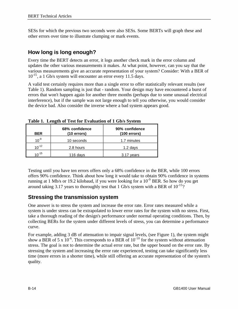
BERT Technical Articles
B-14 GB1400 User Manual
SESs for which the previous two seconds were also SESs. Some BERTs will graph these andother errors over time to illustrate clumping or mark events.
How long is long enough?Every time the BERT detects an error, it logs another check mark in the error column andupdates the other various measurements it makes. At what point, however, can you say that thevarious measurements give an accurate representation of your system? Consider: With a BER of10-15, a 1 Gb/s system will encounter an error every 11.5 days.
A valid test certainly requires more than a single error to offer statistically relevant results (seeTable 1). Random sampling is just that - random. Your design may have encountered a burst oferrors that won't happen again for another three months (perhaps due to some unusual electricalinterference), but if the sample was not large enough to tell you otherwise, you would considerthe device bad. Also consider the inverse where a bad system appears good.
Table 1. Length of Test for Evaluation of 1 Gb/s System
BER68% confidence
(10 errors)90% confidence
(100 errors)
10-9 10 seconds 1.7 minutes
10-12 2.8 hours 1.2 days
10-15 116 days 3.17 years
Testing until you have ten errors offers only a 68% confidence in the BER, while 100 errorsoffers 90% confidence. Think about how long it would take to obtain 90% confidence in systemsrunning at 1 Mb/s or 19.2 kilobaud, if you were looking for a 10-9 BER. So how do you getaround taking 3.17 years to thoroughly test that 1 Gb/s system with a BER of 10-15?
Stressing the transmission systemOne answer is to stress the system and increase the error rate. Error rates measured while asystem is under stress can be extrapolated to lower error rates for the system with no stress. First,take a thorough reading of the design's performance under normal operating conditions. Then, bycollecting BERs for the system under different levels of stress, you can determine a performancecurve.
For example, adding 3 dB of attenuation to impair signal levels, (see Figure 1), the system mightshow a BER of 5 x 10⁻⁶. This corresponds to a BER of 10-10 for the system without attenuationstress. The goal is not to determine the actual error rate, but the upper bound on the error rate. Bystressing the system and increasing the error rate experienced, testing can take significantly lesstime (more errors in a shorter time), while still offering an accurate representation of the system'squality.
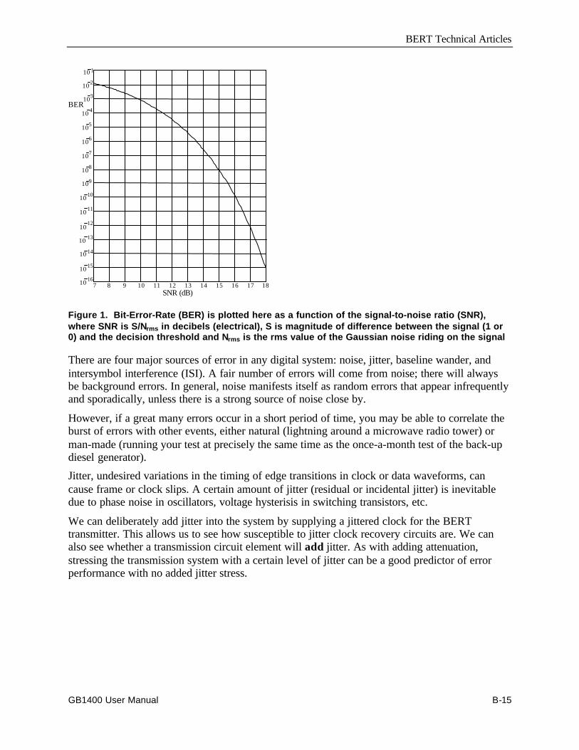
BERT Technical Articles
GB1400 User Manual B-15
7 8 9 10 11 12 13 14 15 16 17 1810 16
10 15
10 14
10 13
1012
10 11
10 10
109
108
107
106
105
BER
SNR (dB)
103
10 4
10 2
10 1
Figure 1. Bit-Error-Rate (BER) is plotted here as a function of the signal-to-noise ratio (SNR),where SNR is S/Nrms in decibels (electrical), S is magnitude of difference between the signal (1 or0) and the decision threshold and Nrms is the rms value of the Gaussian noise riding on the signal
There are four major sources of error in any digital system: noise, jitter, baseline wander, andintersymbol interference (ISI). A fair number of errors will come from noise; there will alwaysbe background errors. In general, noise manifests itself as random errors that appear infrequentlyand sporadically, unless there is a strong source of noise close by.
However, if a great many errors occur in a short period of time, you may be able to correlate theburst of errors with other events, either natural (lightning around a microwave radio tower) orman-made (running your test at precisely the same time as the once-a-month test of the back-updiesel generator).
Jitter, undesired variations in the timing of edge transitions in clock or data waveforms, cancause frame or clock slips. A certain amount of jitter (residual or incidental jitter) is inevitabledue to phase noise in oscillators, voltage hysterisis in switching transistors, etc.
We can deliberately add jitter into the system by supplying a jittered clock for the BERTtransmitter. This allows us to see how susceptible to jitter clock recovery circuits are. We canalso see whether a transmission circuit element will add jitter. As with adding attenuation,stressing the transmission system with a certain level of jitter can be a good predictor of errorperformance with no added jitter stress.

BERT Technical Articles
B-16 GB1400 User Manual
ISI errors are caused when particular patterns (symbols) of data interfere with each other, leadingto blurring and smearing of signals. An example of ISI can be illustrated by following a squarewave (1010....). When the signal leaves the transmitter, the corners of the square wave aresharply defined. As the signal travels a couple of miles over a transmission medium, attenuation(a function of distance) sets in. The digital waveform experiences phase delay, dependent uponthe frequency of the signal components. As a consequence, the square corners become morerounded and blend into each other, making it difficult to tell where a pulse starts and stops. Thetails of data pulses interfere with following data and reduce the eye opening (example shown inFigure 2).
Superimposedpulses with jittermodulation
+ Peak- Peak
Ideal pulseposition
Jitter modulation
Figure 2. Example of a "Eye Diagram" as viewed on an oscilloscope. Pulse rounding is due tophase dispersion, causing ISI.
By purposely adding noise, jitter or stress patterns, you can stress your design. An externalattenuator can crank a known dB of loss into the transmission path. BERTs can add jitter byusing a dithered clock so as to impair timing. Baseline wander can be tested by pattern stressing(what happens after a long string of 0s?), causing dc drift and reducing the amplitude of thedecision threshold.
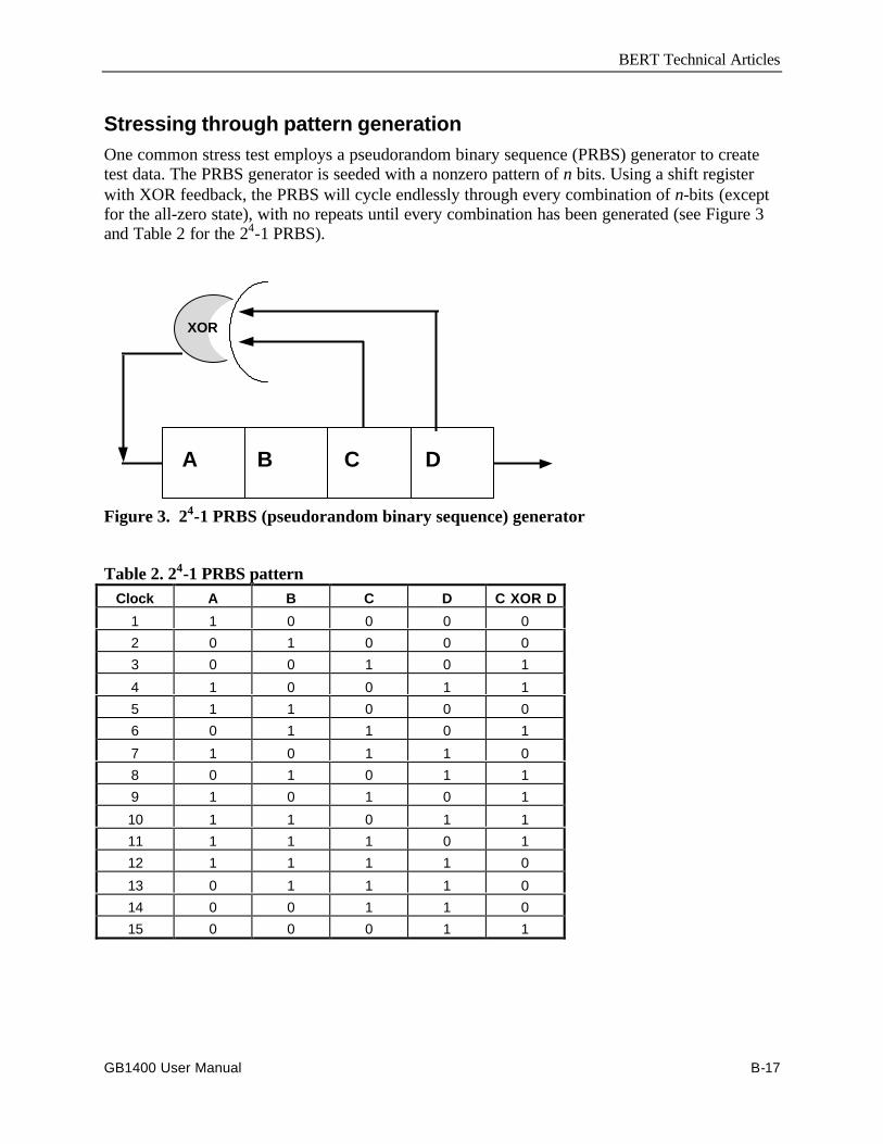
BERT Technical Articles
GB1400 User Manual B-17
Stressing through pattern generationOne common stress test employs a pseudorandom binary sequence (PRBS) generator to createtest data. The PRBS generator is seeded with a nonzero pattern of n bits. Using a shift registerwith XOR feedback, the PRBS will cycle endlessly through every combination of n-bits (exceptfor the all-zero state), with no repeats until every combination has been generated (see Figure 3and Table 2 for the 24-1 PRBS).
A B C D
XOR
Figure 3. 24-1 PRBS (pseudorandom binary sequence) generator
Table 2. 24-1 PRBS patternClock A B C D C XOR D
1 1 0 0 0 02 0 1 0 0 03 0 0 1 0 1
4 1 0 0 1 15 1 1 0 0 06 0 1 1 0 1
7 1 0 1 1 08 0 1 0 1 19 1 0 1 0 1
10 1 1 0 1 111 1 1 1 0 112 1 1 1 1 0
13 0 1 1 1 014 0 0 1 1 015 0 0 0 1 1
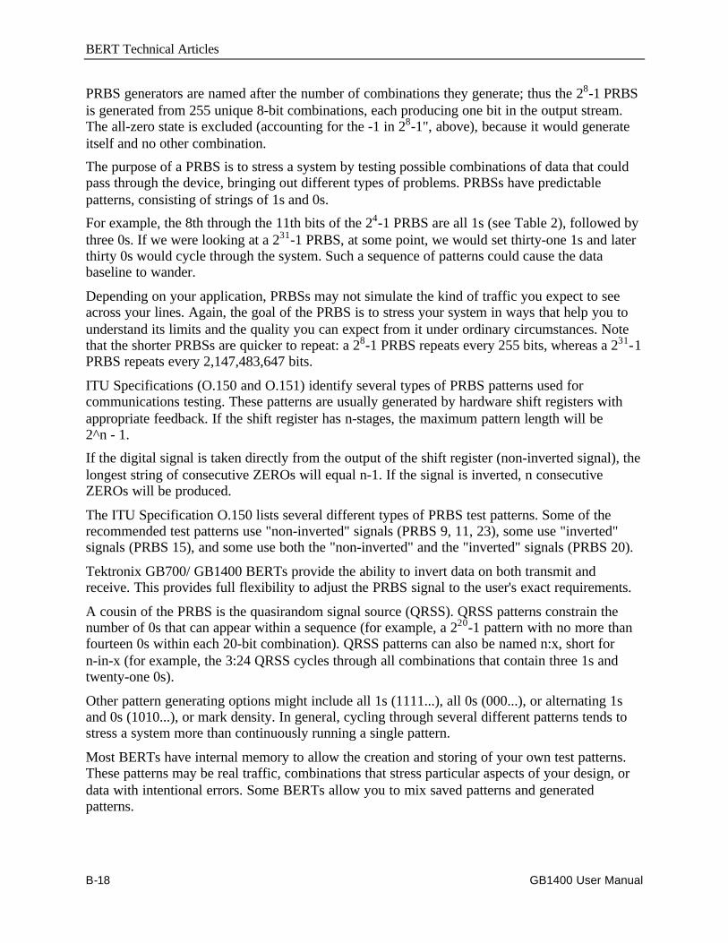
BERT Technical Articles
B-18 GB1400 User Manual
PRBS generators are named after the number of combinations they generate; thus the 28-1 PRBSis generated from 255 unique 8-bit combinations, each producing one bit in the output stream.The all-zero state is excluded (accounting for the -1 in 28-1", above), because it would generateitself and no other combination.
The purpose of a PRBS is to stress a system by testing possible combinations of data that couldpass through the device, bringing out different types of problems. PRBSs have predictablepatterns, consisting of strings of 1s and 0s.
For example, the 8th through the 11th bits of the 24-1 PRBS are all 1s (see Table 2), followed bythree 0s. If we were looking at a 231-1 PRBS, at some point, we would set thirty-one 1s and laterthirty 0s would cycle through the system. Such a sequence of patterns could cause the databaseline to wander.
Depending on your application, PRBSs may not simulate the kind of traffic you expect to seeacross your lines. Again, the goal of the PRBS is to stress your system in ways that help you tounderstand its limits and the quality you can expect from it under ordinary circumstances. Notethat the shorter PRBSs are quicker to repeat: a 28-1 PRBS repeats every 255 bits, whereas a 231-1PRBS repeats every 2,147,483,647 bits.
ITU Specifications (O.150 and O.151) identify several types of PRBS patterns used forcommunications testing. These patterns are usually generated by hardware shift registers withappropriate feedback. If the shift register has n-stages, the maximum pattern length will be2^n - 1.
If the digital signal is taken directly from the output of the shift register (non-inverted signal), thelongest string of consecutive ZEROs will equal n-1. If the signal is inverted, n consecutiveZEROs will be produced.
The ITU Specification O.150 lists several different types of PRBS test patterns. Some of therecommended test patterns use "non-inverted" signals (PRBS 9, 11, 23), some use "inverted"signals (PRBS 15), and some use both the "non-inverted" and the "inverted" signals (PRBS 20).
Tektronix GB700/ GB1400 BERTs provide the ability to invert data on both transmit andreceive. This provides full flexibility to adjust the PRBS signal to the user's exact requirements.
A cousin of the PRBS is the quasirandom signal source (QRSS). QRSS patterns constrain thenumber of 0s that can appear within a sequence (for example, a 220-1 pattern with no more thanfourteen 0s within each 20-bit combination). QRSS patterns can also be named n:x, short forn-in-x (for example, the 3:24 QRSS cycles through all combinations that contain three 1s andtwenty-one 0s).
Other pattern generating options might include all 1s (1111...), all 0s (000...), or alternating 1sand 0s (1010...), or mark density. In general, cycling through several different patterns tends tostress a system more than continuously running a single pattern.
Most BERTs have internal memory to allow the creation and storing of your own test patterns.These patterns may be real traffic, combinations that stress particular aspects of your design, ordata with intentional errors. Some BERTs allow you to mix saved patterns and generatedpatterns.

BERT Technical Articles
GB1400 User Manual B-19
For example, you could use a saved pattern to create an ATM header and a generated pattern topopulate the packet with random data, allowing you to build test data that looks more like "livetraffic". If you are testing an error-correcting circuit on a modem, the transmitted pattern couldhave parity errors that the modem should correct. Because the receiver can reference differentpatterns independent of each other, the "expected" pattern could reflect what the corrected datashould look like with the errors fixed.
= = = = = = = = = = = = = =

BERT Technical Articles
B-20 GB1400 User Manual
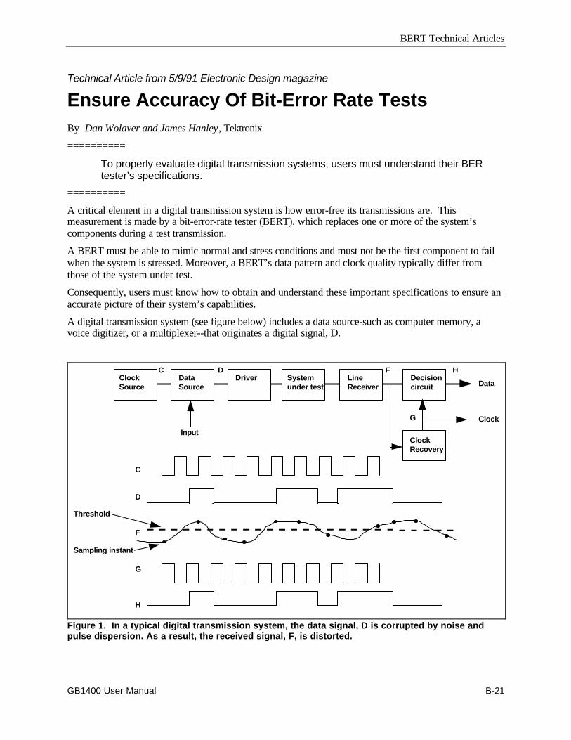
BERT Technical Articles
GB1400 User Manual B-21
Technical Article from 5/9/91 Electronic Design magazine
Ensure Accuracy Of Bit-Error Rate TestsBy Dan Wolaver and James Hanley, Tektronix
==========
To properly evaluate digital transmission systems, users must understand their BERtester’s specifications.
==========
A critical element in a digital transmission system is how error-free its transmissions are. Thismeasurement is made by a bit-error-rate tester (BERT), which replaces one or more of the system’scomponents during a test transmission.
A BERT must be able to mimic normal and stress conditions and must not be the first component to failwhen the system is stressed. Moreover, a BERT’s data pattern and clock quality typically differ fromthose of the system under test.
Consequently, users must know how to obtain and understand these important specifications to ensure anaccurate picture of their system’s capabilities.
A digital transmission system (see figure below) includes a data source-such as computer memory, avoice digitizer, or a multiplexer--that originates a digital signal, D.
Threshold
Sampling instant
C
D
F
G
H
DataSource
Driver Systemunder test
LineReceiver
Decisioncircuit
ClockRecovery
ClockSource
Input
C D F H
G
Data
Clock
Figure 1. In a typical digital transmission system, the data signal, D is corrupted by noise andpulse dispersion. As a result, the received signal, F, is distorted.
BERT Technical Articles
B-22 GB1400 User Manual
A clock source produces a clock signal, C, that times the occurrence of each bit in the digital signal. Adriver, which may be a power amplifier, a laser diode, an RF modulator, or a tape head, prepares thesignal for the system under test. The system under test can be a transmission line with repeaters, or anoptical fiber link, microwave radio link, or digital tape recorder. The received signal, F, exhibits the noiseand pulse dispersion that the transmission system adds to the digital signal.
If the noise and distortion are within limits, the decision circuit can correctly decide whether the originalbit was a 1 or a 0. The circuit does this by comparing F (at sampling instants determined by clock signalG) with a threshold halfway between the two levels. If no errors are made in the decision process, H is adelayed replica of the original data signal D. A clock-recovery circuit generates G from information indata signal F.
A malfunction in any system component can cause the recovered data to differ from the original data. Theprimary job of a BERT is to determine the system’s error rate rather than isolate the faulty component.But for the sake of convenience, the BERT may replace the clock source in the transmitter or receiver.
In this case, some fault isolation may be possible by comparing the performance of the system clocksources with that of the BERT. But for the comparison to be meaningful, users must understand thetiming jitter specifications of both units.
To measure the system’s error rate, the test set performs one or more of the following pairs of functions:
• data-pattern generation and error monitoring;
• clock generation and recovery; and,
• jitter generation and measurement.
Which functions are used depends on how the BERT is connected in the system.
The simplest measuring technique (see the following figure) is to replace the system’s data source withthe BERT’s data-pattern generator and have the BERT receiver monitor the recovered signal for errors.
The data signal D then becomes D′. The data-pattern generator can mimic typical traffic by creatingpseudorandom patterns, or it can stress the system by outputting fixed patterns stored in memory.
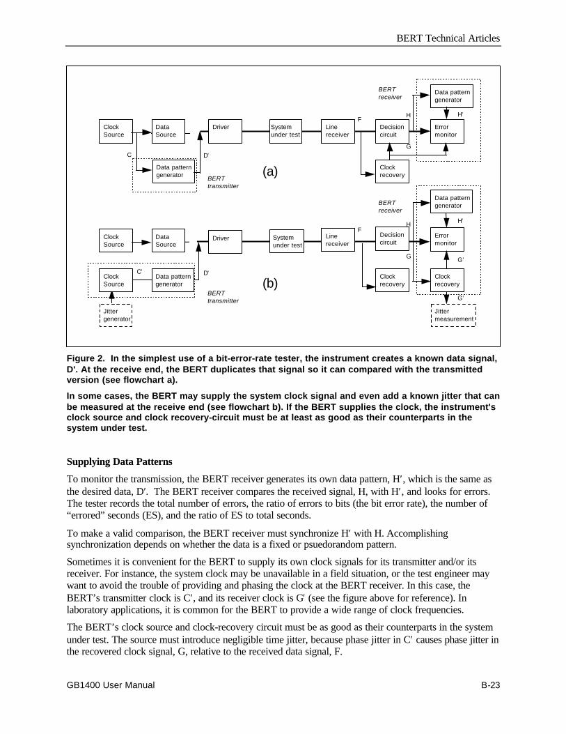
BERT Technical Articles
GB1400 User Manual B-23
ClockSource
DataSource
Driver Systemunder test
Linereceiver
Clockrecovery
Decisioncircuit
Jittermeasurement
Clockrecovery
Errormonitor
Data patterngenerator
Errormonitor
Data patterngenerator
Data patterngenerator
ClockSource
ClockSource
DataSource
Driver Systemunder test
Line receiver
Clockrecovery
Decisioncircuit
Jittergenerator
Data patterngenerator (a)
(b)
BERTtransmitter
BERTtransmitter
BERTreceiver
BERTreceiver
C D’
FH
G
H
G
F
D’C’
H’
G’
G’
H’
Figure 2. In the simplest use of a bit-error-rate tester, the instrument creates a known data signal,D'. At the receive end, the BERT duplicates that signal so it can compared with the transmittedversion (see flowchart a).
In some cases, the BERT may supply the system clock signal and even add a known jitter that canbe measured at the receive end (see flowchart b). If the BERT supplies the clock, the instrument'sclock source and clock recovery-circuit must be at least as good as their counterparts in thesystem under test.
Supplying Data Patterns
To monitor the transmission, the BERT receiver generates its own data pattern, H′, which is the same asthe desired data, D′. The BERT receiver compares the received signal, H, with H′, and looks for errors.The tester records the total number of errors, the ratio of errors to bits (the bit error rate), the number of“errored” seconds (ES), and the ratio of ES to total seconds.
To make a valid comparison, the BERT receiver must synchronize H′ with H. Accomplishingsynchronization depends on whether the data is a fixed or psuedorandom pattern.
Sometimes it is convenient for the BERT to supply its own clock signals for its transmitter and/or itsreceiver. For instance, the system clock may be unavailable in a field situation, or the test engineer maywant to avoid the trouble of providing and phasing the clock at the BERT receiver. In this case, theBERT’s transmitter clock is C′, and its receiver clock is G′ (see the figure above for reference). Inlaboratory applications, it is common for the BERT to provide a wide range of clock frequencies.
The BERT’s clock source and clock-recovery circuit must be as good as their counterparts in the systemunder test. The source must introduce negligible time jitter, because phase jitter in C′ causes phase jitter inthe recovered clock signal, G, relative to the received data signal, F.
BERT Technical Articles
B-24 GB1400 User Manual
Likewise, the BERT’s clock-recovery circuit must tolerate at least as much jitter as the system’s recoverycircuit without causing errors.
Although the BERT clock source should be essentially jitter-free to test the digital transmission systemunder normal conditions, users may wish to stress the system at times. In that case, the BERT mustgenerate controlled jitter. To do so, some BERTs have a jitter generator that can sinusoidally modulate thephase of the clock source.
On the receive end, the BERT monitors the effect of the controlled jitter in two ways: First it looks for anincreased error rate, then it measures the jitter remaining in the recovered data. The second measurementyields the system’s jitter-transfer function. The jitter-measurement circuit can also be used without thejitter generator to measure the system’s own jitter.
The BERT transmitter’s principal task is to send a data pattern to the transmission system. The mostgeneral scheme is a repeating pattern that can be as short as 8 bits or as long as thousands of bits. Userscan design the pattern to exercise the system in a number of ways, including noise margin and clock-recovery stressing.
Noise-Margin Stressing
The quality of signal F determines whether the digital transmission system decides correctly between alogic 1 and a logic 0. That quality depends on the noise margin, which is the separation between F and thelogic threshold at the sampling point. Any distortion (usually due to a nonflat frequency response in thelinear channel) reduces the noise margin. If the noise margin is large, the error rate is essentially zero anddoesn’t indicate the margin.
A BERT, however, can measure the noise margin by reducing it in a controlled way until the error rate issignificant. The measurement uses what’s called baseline wander. Most transmission systems are ACcoupled to suppress the effects of biasing and DC offsets (see the following figure).
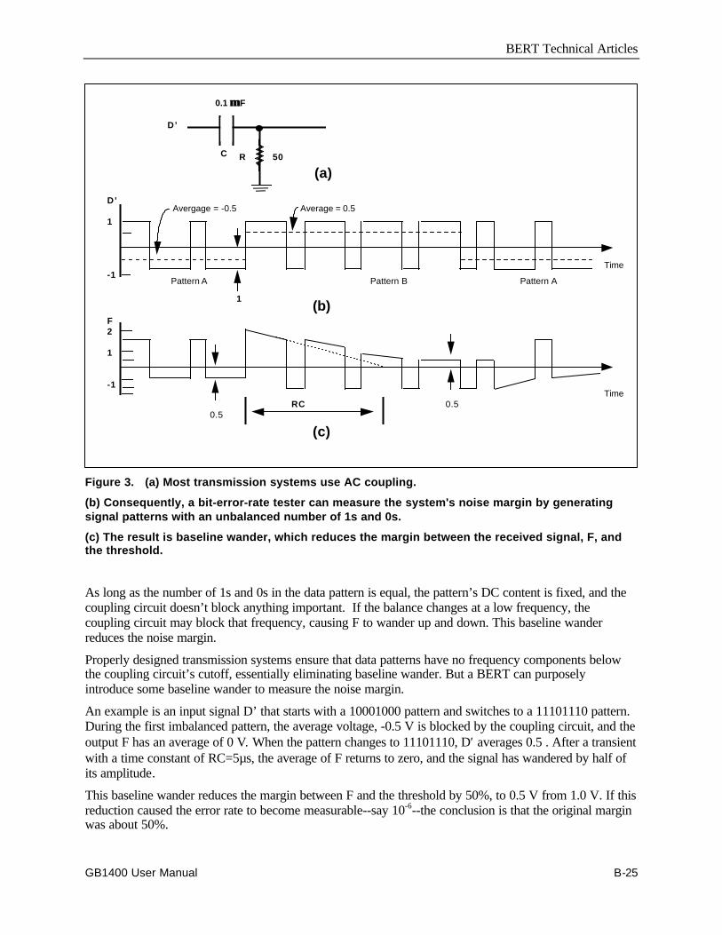
BERT Technical Articles
GB1400 User Manual B-25
D’
1
-1
Avergage = -0.5 Average = 0.5
Pattern A Pattern B Pattern A
Time
1
F2
1
-1
0.5RC 0.5
Time
(b)
(c)
R 50
(a)
D’
C
0.1 Fµµ
Figure 3. (a) Most transmission systems use AC coupling.
(b) Consequently, a bit-error-rate tester can measure the system's noise margin by generatingsignal patterns with an unbalanced number of 1s and 0s.
(c) The result is baseline wander, which reduces the margin between the received signal, F, andthe threshold.
As long as the number of 1s and 0s in the data pattern is equal, the pattern’s DC content is fixed, and thecoupling circuit doesn’t block anything important. If the balance changes at a low frequency, thecoupling circuit may block that frequency, causing F to wander up and down. This baseline wanderreduces the noise margin.
Properly designed transmission systems ensure that data patterns have no frequency components belowthe coupling circuit’s cutoff, essentially eliminating baseline wander. But a BERT can purposelyintroduce some baseline wander to measure the noise margin.
An example is an input signal D’ that starts with a 10001000 pattern and switches to a 11101110 pattern.During the first imbalanced pattern, the average voltage, -0.5 V is blocked by the coupling circuit, and theoutput F has an average of 0 V. When the pattern changes to 11101110, D′ averages 0.5 . After a transientwith a time constant of RC=5µs, the average of F returns to zero, and the signal has wandered by half ofits amplitude.
This baseline wander reduces the margin between F and the threshold by 50%, to 0.5 V from 1.0 V. If thisreduction caused the error rate to become measurable--say 10-6--the conclusion is that the original marginwas about 50%.
BERT Technical Articles
B-26 GB1400 User Manual
To stress the noise margin continuously, the tester alternates between 10001000 (pattern A) and11101110 (pattern B) at a frequency below the AC coupling circuit’s cutoff frequency. Each patterncontinues long enough for the circuit’s transient to die out. A duration of 3.14 time constants, or πRC, issufficient. Therefore, the complete fixed pattern stored in memory has a period of at least 2πRC. Thefrequency of the pattern is at most 1/2πRC, which is the cutoff frequency, fL, of the coupling circuit.
Then if the bit rate is fc, the number of bits in the fixed pattern is:
N ≥ fc / fL
For example, if fl=32kHz and fc=1 Gbit/s, the fixed data pattern must be at least N = 1 Gbit/s/ 32kHz =31,200 bits long.
Users can create different stress levels by combining the above patterns with patterns that have an equalnumber of 1s and 0s, thus causing no stress in a system with AC coupling. For example, the pattern11001100 won’t change the DC content or noise margin. By combining various amounts of this balancedpattern with the previous unbalanced patterns, users can stress the system to varying degrees, up to 50%(see table below).
Table 1. Data patterns for noise margin stressing
Pattern A Pattern B Margin reduction
1100110011001100 1100110011001100 0 %
1000110011001100 1110110011001100 12.5 %
1000110010001100 1110110011101100 25.0 %
1000100010001000 1110111011101110 50.0%
Other patterns such as 1000000010000000, stress the noise margin by more than 50%, but they also stressthe clock-recovery circuit, which may be undesirable.
Users who want to stress the clock-recovery circuit can do so by varying the transition density. This isbecause the system’s receiver gets its information from the received data signal. For nonreturn-to-zerodata, the clock information is in the data transitions. Random data contains an equal number of 0-to-1 and1-to-0 transitions, and a clock-recovery circuit is usually designed to expect this 50% transitions density.The circuit may have trouble with either a greater or lesser density.

BERT Technical Articles
GB1400 User Manual B-27
The simplest fixed pattern with a 50% transition density is again 11001100. The patterns in Table 1 thatstress noise margin by varying the balance of 1s and 0s also maintain a 50% transition density. Similarly,patterns that stress the clock-recovery circuit by varying transition density should keep the 1s and 0s inbalance (see the following table).
Table 2. Data patterns for clock recovery stressing
Pattern Transition density
1010101010101010 100%
1010110010101100 75%
1100110011001100 50% (normal)
11001110001100111000 40%
111000111000111000 33%
11100011100011110000 30%
1111000011110000 25%
As the transition density is increased or decreased from 50%, the clock-recovery circuit will fail and theerror rate will become significant. A well-designed clock recovery will typically tolerate transitiondensities between 100% and 25% without causing errors.
Data Patterns Stored
Fixed patterns can also be designed to simulate valid line formats in telecommunications.
One such format is DS2, the third level in the North American digital hierarchy at 6.312 Mbits/s. TheDS2 frame is 1176 bits long, organized into 24 groups of 49 bits. The first bit in each group of 49 is aframing bit or a control bit, and the rest are data bits. A BERT transmitter can generate such a pattern totest terminal equipment that looks for the framing and control bits.
Fixed data patterns are stored in the BERT transmitter. User-defined patterns are stored in RAM, andmanufacturer-provided patterns are stored in ROM.
The BERT receiver must be programmed to produce the same data pattern as the transmitter. The receiversynchronizes its pattern, H’, to the received data pattern, H, on the basis of error rate. If the error rate isgreater than some set level, say 10-2, H’ is shifted one bit by dropping a clock pulse. This continues untilthe synchronization is achieved, as indicated by an error rate less than 10-2.
Another type of pattern, a psuedorandom bit sequence (PRBS), simulates live traffic. A PRBS has all ofthe properties of a random sequence but is periodic. A fixed pattern could be programmed to produce aPRBS, but a simple circuit can generate a pattern millions of bits long with only 20 to 30 bits of memory.Common pattern lengths are N=27-1, 215-1, and 223-1.
PRBS patterns can stress the noise margin and the clock recovery as fixed patterns do. But it is donerandomly, somewhat like live traffic. When averaged over the whole sequence, the number of 1s and 0salmost equal (actually different by one), and transition density is 50%. Over a short term, though, theaverages can be very different, stressing both noise margin and clock recovery for periods of time.

BERT Technical Articles
B-28 GB1400 User Manual
To stress the noise margin, the PRBS spectrum must have components below the coupling circuit’s cutofffrequency, fL. For example, a 23-stage PRBS generator with a bit rate, fc, of 44.7 Mbits/s has a patternlength of 223-1=8,388,607 bits.
The fundamental frequency, fF, is fc/8,388,607=5.33 Hz. If fL=32 kHz, thousands of the pattern’s spectralcomponents are removed. The fraction of power removed is given by πfL/fc, and the square root of thatfigure is the rms error as a fraction of the signal level:
rms error = πfL/fc = 0.047
This error appears as Gaussian noise with an rms value that is 4.7% of the noise margin. The morespectral components below the cutoff frequency, the more Gaussian the noise is. However, if fundamentalwould be the PRBS pattern length was 27-1, the 350 kHz, which is greater than fL. The noise marginwouldn’t be stressed, and the formula for rms error wouldn’t hold.
Similarly, a PRBS pattern will stress the clock-recovery circuit if the pattern’s fundamental is within theB. If it is, the pattern introduces random fitter in the recovered clock. The jitter’s
magnitude depends on fB and on offsets within the circuit. The rms jitter is not a function of the PRBSpattern length, but the peak jitter increases with pattern length.
Examining Jitter
An important factor in a data transmission system is jitter. Ideally, all clock and data signals in thesystems have a constant frequency with no phase modulation. In practice, a clock source has some phasemodulation, or jitter, and noise and imperfect equalization introduce additional jitter. The followingdiscussion examines clock-source jitter alone, assuming that noise and distortion contribute no jitter.
If the received data waveform, F, is viewed on an oscilloscope synchronized data, the 1s and 0s overlap toproduce an “eye” pattern (see figure below).
+ Peak- Peak
Ideal pulseposition
Jitter modulation
Superimposed pulseswith jitter modulation
Figure 4. Viewed on an oscilloscope synchronized to the received data, phase error, or jitter, θθeshows up as a widening of the recovered clock's waveform.
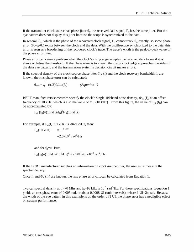
BERT Technical Articles
GB1400 User Manual B-29
If the transmitter clock source has phase jitter θi, the received data signal, F, has the same jitter. But theeye pattern does not display this jitter because the scope is synchronized to the data.
In general, θo, which is the phase of the recovered clock signal, G, cannot track θi, exactly, so some phaseerror (θe=θi-θo) exists between the clock and the data. With the oscilloscope synchronized to the data, thiserror is seen as a broadening of the recovered clock’s trace. The trace’s width is the peak-to-peak value ofthe phase error jitter.
Phase error can cause a problem when the clock’s rising edge samples the received data to see if it isabove or below the threshold. If the phase error is too great, the rising clock edge approaches the sides ofthe data eye pattern, and the transmission system’s decision circuit makes errors.
If the spectral density of the clock-source phase jitter Φ θi (f) and the clock recovery bandwidth fB areknown, the rms phase error can be calculated:
θerms= (π/2)fBΦθi(fB) (Equation 1)
BERT manufacturers sometimes specify the clock’s single-sideband noise density, Φ vi (f), at an offsetfrequency of 10 kHz, which is also the value of Φvi (10 kHz). From this figure, the value of Fqi (fB) canbe approximated by:
Fqi (fB)=(10 kHz/fB)2Fqi(10 kHz).
For example, if Fvi(fc+10 kHz) is -84dBc/Hz, then:
Fqi(10 kHz) =10-84/10
=2.5×10⁻⁹ rad2/Hz
and for fB=16 kHz,
Fqi(fB)=(10 kHz/16 kHz)2×(2.5×10-9)=10-9 rad2/Hz.
If the BERT manufacturer supplies no information on clock-source jitter, the user must measure thespectral density.
Once fB and Φqi(fB) are known, the rms phase error qerms can be calculated from Equation 1.
Typical spectral density at fc=70 Mhz and fB=16 kHz is 10-9 rad2/Hz. For these specifications, Equation 1yields an rms phase error of 0.005 rad, or about 0.0008 UI (unit intervals), where 1 UI=2π rad. Becausethe width of the eye pattern in this example is on the order o f1 UI, the phase error has a negligible effecton system performance.
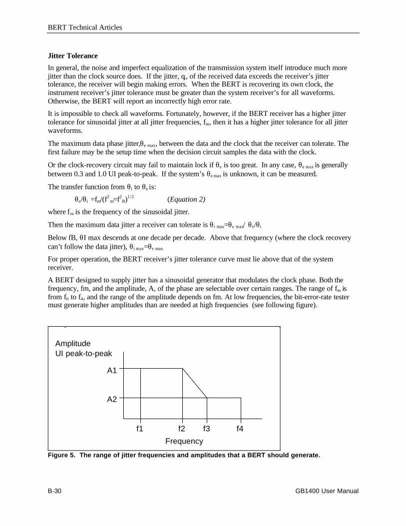
BERT Technical Articles
B-30 GB1400 User Manual
Jitter Tolerance
In general, the noise and imperfect equalization of the transmission system itself introduce much morejitter than the clock source does. If the jitter, qi, of the received data exceeds the receiver’s jittertolerance, the receiver will begin making errors. When the BERT is recovering its own clock, theinstrument receiver’s jitter tolerance must be greater than the system receiver’s for all waveforms.Otherwise, the BERT will report an incorrectly high error rate.
It is impossible to check all waveforms. Fortunately, however, if the BERT receiver has a higher jittertolerance for sinusoidal jitter at all jitter frequencies, fm, then it has a higher jitter tolerance for all jitterwaveforms.
The maximum data phase jitter,θe max, between the data and the clock that the receiver can tolerate. Thefirst failure may be the setup time when the decision circuit samples the data with the clock.
Or the clock-recovery circuit may fail to maintain lock if θe is too great. In any case, θe max is generallybetween 0.3 and 1.0 UI peak-to-peak. If the system’s θe max is unknown, it can be measured.
The transfer function from θi to θe is:
θe/θi=fm/(f2m=f2
B)1/2 (Equation 2)
where fm is the frequency of the sinusoidal jitter.
Then the maximum data jitter a receiver can tolerate is θi max=θe max/θe/θi
Below fB, θI max descends at one decade per decade. Above that frequency (where the clock recoverycan’t follow the data jitter), θi max=θe max.
For proper operation, the BERT receiver’s jitter tolerance curve must lie above that of the systemreceiver.
A BERT designed to supply jitter has a sinusoidal generator that modulates the clock phase. Both thefrequency, fm, and the amplitude, A, of the phase are selectable over certain ranges. The range of fm isfrom f0 to f4, and the range of the amplitude depends on fm. At low frequencies, the bit-error-rate testermust generate higher amplitudes than are needed at high frequencies (see following figure).
A1
A2
f1 f2 f3 f4
Frequency
AmplitudeUI peak-to-peak
Figure 5. The range of jitter frequencies and amplitudes that a BERT should generate.

BERT Technical Articles
GB1400 User Manual B-31
A BERT designed to measure jitter has a phase demodulator connected to the covered clock. The range offm is from f1=10 Hz to f4; the amplitude depends on fm.
The BERT’s jitter generation and jitter measurements specifications should be somewhat higher than themaximum jitter that a system can typically tolerate. As a result, a BERT with jitter generation can find areceiver’s θe max by setting fm=f4 and increasing A until the receiver begins to make errors. In addition, theclock-recovery bandwidth, fB, can be estimated by lowering fm until the jitter tolerance begins to exceedθe max.
BERT Affects Accuracy
Several BERT characteristics can affect the accuracy of system measurements. For instance, a BERTtransmitter may have a very jittery clock source, such as an open-loop voltage-controlled oscillator. If so,the system will have a higher error rate or less margin than when the system’s clock source is used.Measuring the clock-source spectral density and calculation θe rms will uncover this problem.
Another snag may be that a BERT receiver has a very narrowband clock-recovery circuit, such as crystalcontrolled phase locked loop. The small fB will probably make the BERT less tolerant of jitter than thesystem its testing. In high jitter situations, therefore, the BERT will report a higher bit error rate than theactual rate. A BERT transmitter with jitter generation can measure its own receiver’s jitter tolerance andthat of the system to see which is greater.
The question of whether a BERT data pattern fairly represents live traffic is more difficult to answer.Experience indicates that long PRBS patterns (N greater than 14 ) stress the system more than most livetraffic does. But it is rare traffic with unusually stressing patterns that is most interesting. Therefore, thebest users can do is to anticipate these patterns and generate them with fixed patterns from the BERTtransmitter.
============
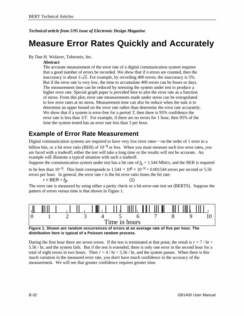
BERT Technical Articles
B-32 GB1400 User Manual
Technical article from 5/95 issue of Electronic Design Magazine
Measure Error Rates Quickly and AccuratelyBy Dan H. Wolaver, Tektronix, Inc.
AbstractThe accurate measurement of the error rate of a digital communication system requiresthat a good number of errors be recorded. We show that if n errors are counted, then theinaccuracy is about 1/ n . For example, by recording 400 errors, the inaccuracy is 5%.But if the error rate is very low, the time to accumulate 400 errors can be hours or days.The measurement time can be reduced by stressing the system under test to produce ahigher error rate. Special graph paper is provided here to plot the error rate as a functionof stress. From this plot, error rate measurements made under stress can be extrapolatedto low error rates at no stress. Measurement time can also be reduce when the task is todetermine an upper bound on the error rate rather than determine the error rate accurately.We show that if a system is error-free for a period T, then there is 95% confidence theerror rate is less than 3/T. For example, if there are no errors for 1 hour, then 95% of thetime the system tested has an error rate less than 3 per hour.
Example of Error Rate MeasurementDigital communication systems are required to have very low error rates−−on the order of 1 error in abillion bits, or a bit error ratio (BER) of 10–9 or less. When you must measure such low error rates, youare faced with a tradeoff; either the test will take a long time or the results will not be accurate. Anexample will illustrate a typical situation with such a tradeoff.Suppose the communication system under test has a bit rate of fb = 1.544 Mbit/s, and the BER is required
to be less than 10–9. This limit corresponds to 1.544 × 106 × 10–9 = 0.001544 errors per second or 5.56errors per hour. In general, the error rate r is the bit error ratio times the bit rate:
r = BER × fb. (1)The error rate is measured by using either a parity check or a bit-error-rate test set (BERTS). Suppose thepattern of errors versus time is that shown in Figure 1.
Time in hours109876542 310
Figure 1. Shown are random occurrences of errors at an average rate of five per hour. Thedistribution here is typical of a Poisson random process.
During the first hour there are seven errors. If the test is terminated at that point, the result is r = 7 / hr >5.56 / hr, and the system fails. But if the test is extended, there is only one error in the second hour for atotal of eight errors in two hours. Then r = 4 / hr < 5.56 / hr, and the system passes. When there is thismuch variation in the measured error rate, you don't have much confidence in the accuracy of themeasurement. We will see that greater confidence requires greater time.
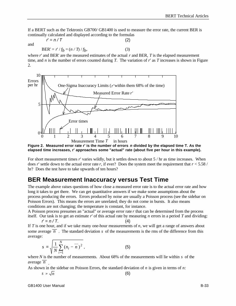
BERT Technical Articles
GB1400 User Manual B-33
If a BERT such as the Tektronix GB700/ GB1400 is used to measure the error rate, the current BER iscontinually calculated and displayed according to the formulas
r' = n / T (2)and
BER' = r' / fb = (n / T) / fb, (3)where r' and BER' are the measured estimates of the actual r and BER, T is the elapsed measurementtime, and n is the number of errors counted during T. The variation of r' as T increases is shown in Figure2.
0 1 2 3 4 5 6 7 8 9 100
5
10
Measured Error Rate r'
One-Sigma Inaccuracy Limits ( within them 68% of the time)
Error times
Errorsper hr
Measurement Time in hoursT
r'
Figure 2. Measured error rate r' is the number of errors n divided by the elapsed time T. As theelapsed time increases, r' approaches some "actual" rate (about five per hour in this example).
For short measurement times r' varies wildly, but it settles down to about 5 / hr as time increases. Whendoes r' settle down to the actual error rate r, if ever? Does the system meet the requirement that r < 5.58 /hr? Does the test have to take upwards of ten hours?
BER Measurement Inaccuracy versus Test TimeThe example above raises questions of how close a measured error rate is to the actual error rate and howlong it takes to get there. We can get quantitative answers if we make some assumptions about theprocess producing the errors. Errors produced by noise are usually a Poisson process (see the sidebar onPoisson Errors). This means the errors are unrelated; they do not come in bursts. It also meansconditions are not changing; the temperature is constant, for instance.A Poisson process presumes an "actual" or average error rate r that can be determined from the processitself. Our task is to get an estimate r' of this actual rate by measuring n errors in a period T and dividing:
r' = n / T. (4)If T is one hour, and if we take many one-hour measurements of n, we will get a range of answers aboutsome average n . The standard deviation σ of the measurements is the rms of the difference from thisaverage:
σ ≡ −=∑1 2
1Nn ni
i
N
( )__
, (5)
where N is the number of measurements. About 68% of the measurements will lie within σ of theaverage n .As shown in the sidebar on Poisson Errors, the standard deviation of n is given in terms of n:
σ ≈ n (6)
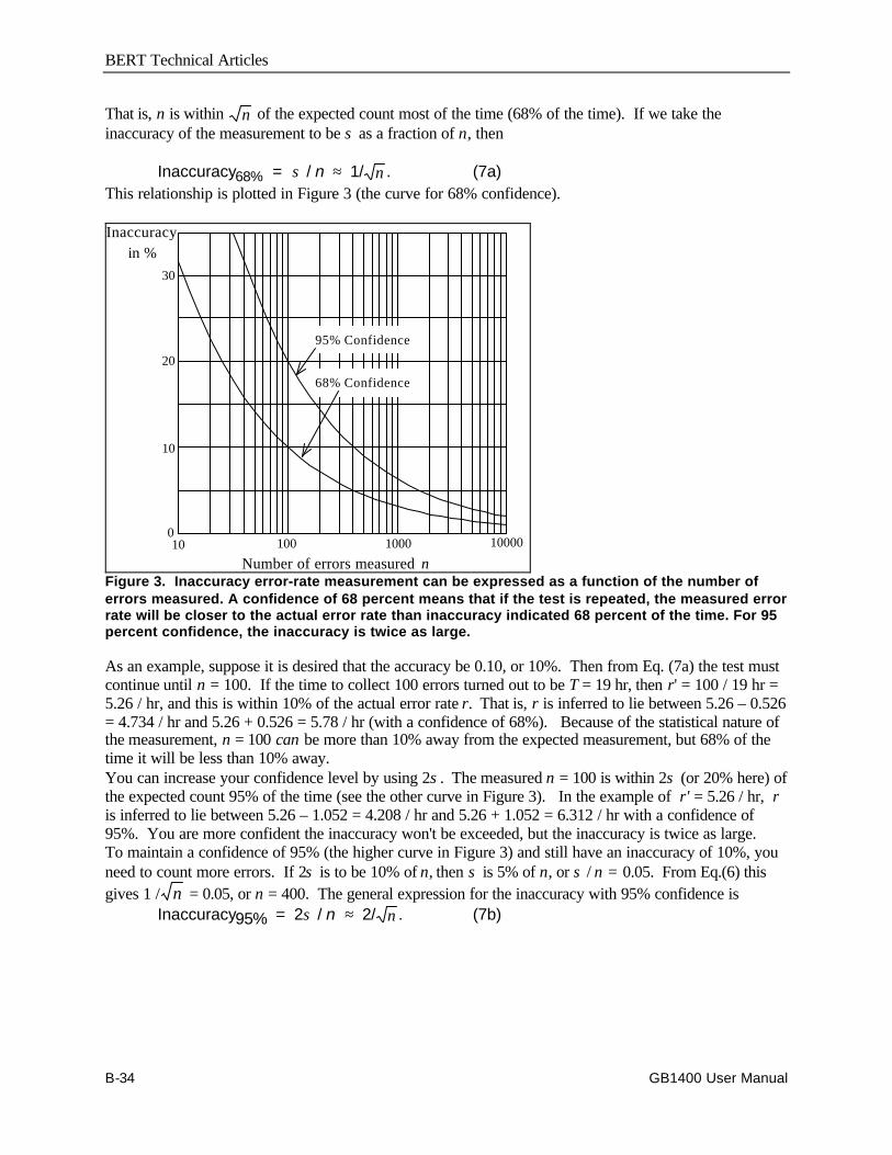
BERT Technical Articles
B-34 GB1400 User Manual
That is, n is within n of the expected count most of the time (68% of the time). If we take theinaccuracy of the measurement to be σ as a fraction of n, then
Inaccuracy68% = σ / n ≈ 1/ n . (7a)This relationship is plotted in Figure 3 (the curve for 68% confidence).
10 100 1000 10000
30
20
10
0
Inaccuracyin %
Number of errors measured n
68% Confidence
95% Confidence
Figure 3. Inaccuracy error-rate measurement can be expressed as a function of the number oferrors measured. A confidence of 68 percent means that if the test is repeated, the measured errorrate will be closer to the actual error rate than inaccuracy indicated 68 percent of the time. For 95percent confidence, the inaccuracy is twice as large.
As an example, suppose it is desired that the accuracy be 0.10, or 10%. Then from Eq. (7a) the test mustcontinue until n = 100. If the time to collect 100 errors turned out to be T = 19 hr, then r' = 100 / 19 hr =5.26 / hr, and this is within 10% of the actual error rate r. That is, r is inferred to lie between 5.26 – 0.526= 4.734 / hr and 5.26 + 0.526 = 5.78 / hr (with a confidence of 68%). Because of the statistical nature ofthe measurement, n = 100 can be more than 10% away from the expected measurement, but 68% of thetime it will be less than 10% away.You can increase your confidence level by using 2σ. The measured n = 100 is within 2σ (or 20% here) ofthe expected count 95% of the time (see the other curve in Figure 3). In the example of r' = 5.26 / hr, ris inferred to lie between 5.26 – 1.052 = 4.208 / hr and 5.26 + 1.052 = 6.312 / hr with a confidence of95%. You are more confident the inaccuracy won't be exceeded, but the inaccuracy is twice as large.To maintain a confidence of 95% (the higher curve in Figure 3) and still have an inaccuracy of 10%, youneed to count more errors. If 2σ is to be 10% of n, then σ is 5% of n, or σ / n = 0.05. From Eq.(6) thisgives 1 / n = 0.05, or n = 400. The general expression for the inaccuracy with 95% confidence is
Inaccuracy95% = 2σ / n ≈ 2/ n . (7b)
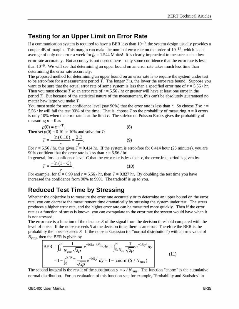
BERT Technical Articles
GB1400 User Manual B-35
Testing for an Upper Limit on Error RateIf a communication system is required to have a BER less than 10–9, the system design usually provides acouple dB of margin. This margin can make the nominal error rate on the order of 10–12, which is anaverage of only one error a week for fb = 1.544 Mbit/s! It is clearly impractical to measure such a lowerror rate accurately. But accuracy is not needed here––only some confidence that the error rate is lessthan 10–9. We will see that determining an upper bound on an error rate takes much less time thandetermining the error rate accurately.The proposed method for determining an upper bound on an error rate is to require the system under testto be error-free for a measurement period T. The longer T is, the lower the error rate bound. Suppose youwant to be sure that the actual error rate of some system is less than a specified error rate of r = 5.56 / hr.Then you must choose T so an error rate of r = 5.56 / hr or greater will have at least one error in theperiod T. But because of the statistical nature of the measurement, this can't be absolutely guaranteed nomatter haw large you make T.You must settle for some confidence level (say 90%) that the error rate is less than r. So choose T so r =5.56 / hr will fail the test 90% of the time. That is, choose T so the probability of measuring n = 0 errorsis only 10% when the error rate is at the limit r. The sidebar on Poisson Errors gives the probability ofmeasuring n = 0 as
p(0) = e–rT. (8)Then set p(0) = 0.10 or 10% and solve for T:
Tr r
= − =ln ( . ) .0 10 2 3. (9)
For r = 5.56 / hr, this gives T = 0.414 hr. If the system is error-free for 0.414 hour (25 minutes), you are90% confident that the error rate is less than r = 5.56 / hr.In general, for a confidence level C that the error rate is less than r, the error-free period is given by
TC
r= − −ln ( )1
. (10)
For example, for C = 0.99 and r = 5.56 / hr, then T = 0.827 hr. By doubling the test time you haveincreased the confidence from 90% to 99%. The tradeoff is up to you.
Reduced Test Time by StressingWhether the objective is to measure the error rate accurately or to determine an upper bound on the errorrate, you can decrease the measurement time dramatically by stressing the system under test. The stressproduces a higher error rate, and the higher error rate can be measured more quickly. Then if the errorrate as a function of stress is known, you can extrapolate to the error rate the system would have when itis not stressed.The error rate is a function of the distance S of the signal from the decision threshold compared with thelevel of noise. If the noise exceeds S at the decision time, there is an error. Therefore the BER is theprobability the noise exceeds S. If the noise is Gaussian (or "normal distribution") with an rms value ofNrms, then the BER is given by
BER
cnorm
= =
= − = −
∞ − −∞
−
∫ ∫
∫
1
2
1
2
11
21
0 5 0 5
0 50
2 2
2
Ne dx e dy
e dy S N
rmsS
x N yS N
yS Nrms
rms
rms
rms
π π
π
. / ./
./( / )
(11)
The second integral is the result of the substitution y = x / Nrms. The function "cnorm" is the cumulativenormal distribution. For an evaluation of this function see, for example, "Probability and Statistics" in
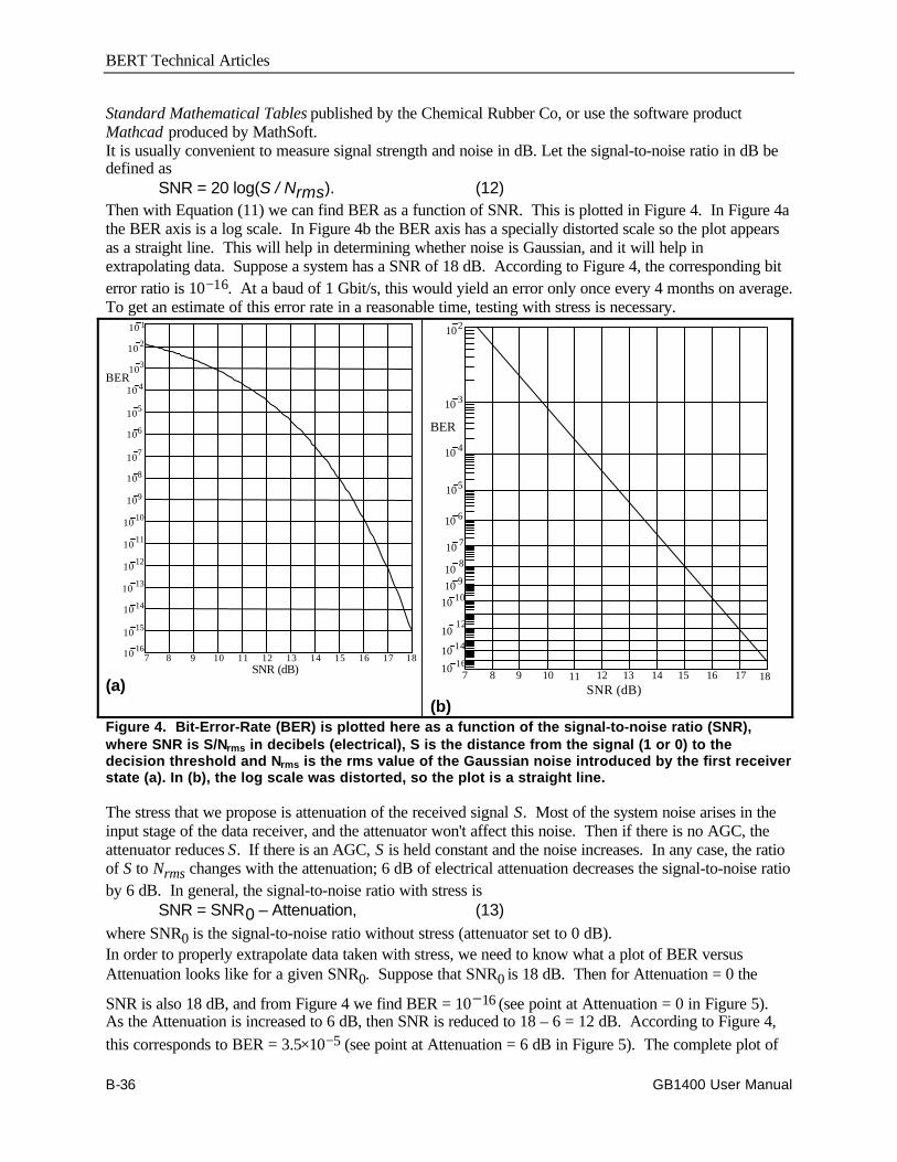
BERT Technical Articles
B-36 GB1400 User Manual
Standard Mathematical Tables published by the Chemical Rubber Co, or use the software productMathcad produced by MathSoft.It is usually convenient to measure signal strength and noise in dB. Let the signal-to-noise ratio in dB bedefined as
SNR = 20 log(S / Nrms). (12)Then with Equation (11) we can find BER as a function of SNR. This is plotted in Figure 4. In Figure 4athe BER axis is a log scale. In Figure 4b the BER axis has a specially distorted scale so the plot appearsas a straight line. This will help in determining whether noise is Gaussian, and it will help inextrapolating data. Suppose a system has a SNR of 18 dB. According to Figure 4, the corresponding biterror ratio is 10−16. At a baud of 1 Gbit/s, this would yield an error only once every 4 months on average.To get an estimate of this error rate in a reasonable time, testing with stress is necessary.
7 8 9 10 11 12 13 14 15 16 17 1810 16
10 15
10 14
10 13
10 12
10 11
10 10
109
108
107
106
105
BER
SNR (dB)
103
10 4
10 2
10 1
(a)10 1610 14
1012
10 1010 910
8
10 7
10 6
105
BER
SNR (dB)
102
10 3
10 4
181716151413121110987
(b)Figure 4. Bit-Error-Rate (BER) is plotted here as a function of the signal-to-noise ratio (SNR),where SNR is S/Nrms in decibels (electrical), S is the distance from the signal (1 or 0) to thedecision threshold and Nrms is the rms value of the Gaussian noise introduced by the first receiverstate (a). In (b), the log scale was distorted, so the plot is a straight line.
The stress that we propose is attenuation of the received signal S. Most of the system noise arises in theinput stage of the data receiver, and the attenuator won't affect this noise. Then if there is no AGC, theattenuator reduces S. If there is an AGC, S is held constant and the noise increases. In any case, the ratioof S to Nrms changes with the attenuation; 6 dB of electrical attenuation decreases the signal-to-noise ratioby 6 dB. In general, the signal-to-noise ratio with stress is
SNR = SNR0 – Attenuation, (13)where SNR0 is the signal-to-noise ratio without stress (attenuator set to 0 dB).In order to properly extrapolate data taken with stress, we need to know what a plot of BER versusAttenuation looks like for a given SNR0. Suppose that SNR0 is 18 dB. Then for Attenuation = 0 the
SNR is also 18 dB, and from Figure 4 we find BER = 10−16 (see point at Attenuation = 0 in Figure 5).As the Attenuation is increased to 6 dB, then SNR is reduced to 18 – 6 = 12 dB. According to Figure 4,this corresponds to BER = 3.5×10⁻⁵ (see point at Attenuation = 6 dB in Figure 5). The complete plot of
BERT Technical Articles
GB1400 User Manual B-37
BER vs. Attenuation appears as a straight line because the BER scale is again distorted. The line here isfor the case SNR0 = 18 dB. For other values of SNR0, the plot would fall parallel to the line in Figure 5.Remember that we are talking about electrical attenuation here; 1 dB of optical attenuation is worth 2 dBof electrical attenuation.
10 1610
14
1012
10 1010
910
8
107
106
105
BER
Attenuation (dB)
102
103
104
11109876543210
Figure 5. BER is plotted as function of electrical-signal attenuation for the case of a system withBER=10-6 for no attenuation. That is, the SNR0 for no attenuation is 18 dB. Then, SNR withattenuation is 18 dB minus attenuation, and BER follows from Figure 4.It isn't practical to plot a curve such as that in Figure 5; it would take too long to plot the points for lowBER. But if the noise is known to be Gaussian and the BER is found to be 3.5×10⁻⁵ for 6 dB ofattenuation, then the BER can be inferred to be 10–16 for no attenuation. It is actually better to plot twopoints for two attenuations and extrapolate to zero attenuation. An example will show how thisextrapolation is done.

BERT Technical Articles
B-38 GB1400 User Manual
Example 1A 44.736-Mbit/s system seems to have a very low error rate; in a five-minute test no errors occurred. It isdecided to use stress to estimate the BER with no stress. When 5 dB of electrical attenuation is placed inthe signal path, 13,400 errors are measured in one second––a BER of 13400 / 44736000 = 3×10⁻⁴. Usinggraph paper like that provided at the end of this article, plot a point at Attenuation = 5 dB and BER = 3×10⁻⁴, as in Figure 6. Then the electrical attenuation is reduced to 3 dB, and 16,100 errors are measured in60 seconds. This is a BER of 16100 / (60 × 1544000) = 6×10⁻⁶, which is also plotted in Figure 6. Astraight line through the two points intersects the BER axis at 10−10, so the unstressed BER would be 10−10 (one error every 3.7 minutes on average.)
10 16
1014
10 12
1010
10 9
10 8
107
106
10 5
BER
Attenuation (dB)
103
104
76543210
Example 1
Example 2
Figure 6. In this extrapolation, we find BER for no attenuation from BER measurements with twoattentuations. In the first example, many errors were measured, resulting in tight control of theextrapolation. In the second, too few errors were measured, creating uncertain BER estimates(see the bars) and a sloppy extrapolation.

BERT Technical Articles
GB1400 User Manual B-39
Note that the line through the points in Figure 6 has about the same slope as the dashed lines. Thisindicates the noise is about Gaussian. As the slope of the plotted line is closer to that of the dashed lines,the noise process is closer to Gaussian, and the extrapolation is more reliable. Departure of the slopefrom the Gaussian could be due to (a) too few errors measured, leading to inaccurate BER values, (b) thepresence of a non-Gaussian noise mechanism such as error bursts, or (c) significant noise in the systembefore the attenuator. (Noise coming into the receiver with the signal is assumed to be less than thatintroduced by the first stage in the receiver.)Whether or not the slope is the expected one, confidence in the extrapolation can always be increased bytaking time to plot out the BER-versus-Attenuation curve once down to very low BER. Thus it may takea day or so to test the first system, but subsequent systems can then be tested quickly with the stress-and-extrapolate method.It is important to measure enough errors that the inaccuracy is low and the extrapolation is valid. Becausemore than 10,000 errors were measured each time, the inaccuracy of the BER measurement is less than1% [see Equation (7a)]. This is small enough that the extrapolated results are accurate, even given themagnification effect of extrapolation. To illustrate the importance of measuring enough errors, we willlook at an example where measuring too few errors leads to uncertain results.
Example 2A 1.544-Mbit/s system is stressed with 6 dB of electrical attenuation. In a one-second interval 54 errorsare measured––a BER of 54 / 1544000 = 3.5×10⁻⁵. But with only 54 errors, the inaccuracy is 14% (seeFigure 3 for 68% confidence). Therefore the BER lies between 3.0×10⁻⁵ and 4.0×10⁻⁵. This uncertaintyis indicated by plotting a bar at 6 dB in Figure 6. Then the electrical attenuation is reduced to 4 dB, and37 errors are measured in 60 seconds. This is a BER of 37 / (60 × 1544000) = 4×10⁻⁷. But with 37errors, the inaccuracy is 16%, and the BER lies between 3.35×10⁻⁷ and 4.65×10⁻⁷. This is also plottedas a bar in Figure 6. Straight lines passing through the two bars sweep out the gray region shown andintersect the BER axis anywhere from 2×10⁻¹⁵ to 1.5×10⁻¹³.The large uncertainty of the extrapolated results in this example is mostly due to the few number of errorsmeasured. A good rule is to measure at least 1000 errors for each point. Another guideline is to make thelarger attenuation at least 1.5 times the smaller; a greater separation between the two points allows betterextrapolation. Also, use as little attenuation as possible so the extrapolation distance is not so great (thisinvolves a trade-off with greater test time).Stressing can also be used to reduce the time required to show that the unstressed BER is below somespecified value. The following example will show how the graph paper provided at the end of the articlecan be used in this way.
Example 3A 1.544-Mbit/s system is to have a BER no more than 10−9. This corresponds to an error rate of r =1544000 × 10−9 = 0.001544 errors per second. For a confidence C = 95% that the BER of the system isless than 10−9, it must test error-free for T = 3 / r = 1943 seconds, or 32 minutes [see Equation (10)].This test time can be shortened by using stressing.Suppose a system was just on the limit, with an unstressed BER of the specified 10−9. Make a plot ofBER versus Attenuation by starting at BER = 10−9 for Attenuation = 0, and draw a straight line parallel tothe dashed lines, as in Figure 7. We see that 3 dB of electrical attenuation would raise a BER of 10−9 to
10−5, or a stressed error rate of rs = 15.44 errors per second. So we stress the system with 3 dB ofattenuation and test it for Ts = 3 / rs = 0.194 seconds. If there are no error in that time, then we have 95%
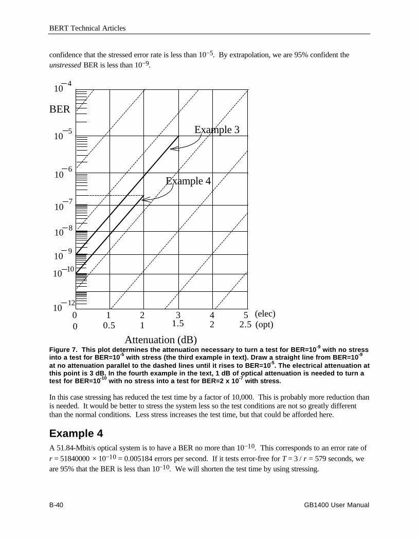
BERT Technical Articles
B-40 GB1400 User Manual
confidence that the stressed error rate is less than 10−5. By extrapolation, we are 95% confident theunstressed BER is less than 10−9.
1012
10 10
109
10 8
107
106
105
BER
Attenuation (dB)
104
543210 (elec)0 0.5 1 1.5 2 2.5 (opt)
Example 3
Example 4
Figure 7. This plot determines the attenuation necessary to turn a test for BER=10-9 with no stressinto a test for BER=10-5 with stress (the third example in text). Draw a straight line from BER=10-9
at no attenuation parallel to the dashed lines until it rises to BER=10-5. The electrical attenuation atthis point is 3 dB. In the fourth example in the text, 1 dB of optical attenuation is needed to turn atest for BER=10-10 with no stress into a test for BER=2 x 10⁻⁷ with stress.
In this case stressing has reduced the test time by a factor of 10,000. This is probably more reduction thanis needed. It would be better to stress the system less so the test conditions are not so greatly differentthan the normal conditions. Less stress increases the test time, but that could be afforded here.
Example 4A 51.84-Mbit/s optical system is to have a BER no more than 10−10. This corresponds to an error rate ofr = 51840000 × 10−10 = 0.005184 errors per second. If it tests error-free for T = 3 / r = 579 seconds, weare 95% that the BER is less than 10−10. We will shorten the test time by using stressing.
BERT Technical Articles
GB1400 User Manual B-41
Make a plot of BER versus Attenuation for SNR0 = 10−10 by starting at BER = 10−10 for Attenuation =0, and draw a straight line parallel to the dashed lines, as in Figure 7. We will use a smaller stress than inExample 3. An optical attenuation of 1 dB (equivalent to 2 dB of electrical attenuation) would raise the
BER to 2×10⁻⁷, or a stressed error rate of rs = 51840000 × 2×10−7 = 10.37 errors per second. So for95% confidence, we stress the system with 1 dB of optical attenuation and test it for Ts = 3 / rs = 0.289seconds. If there are no errors in that time, then we have 95% confidence that the stressed error rate isless than 2×10⁻⁷. By extrapolation, we are 95% confident the unstressed BER is less than 10−10. In thiscase stressing has reduced the test time by a factor of 2000.
SummaryThe inaccuracy of an error rate measurement is not due to any fault of the measurement equipment.Rather the inaccuracy come from incomplete knowledge when too few errors are observed. Therefore theaccuracy can be improved only by taking more time to do the measurement. A good rule of thumb is thatthe inaccuracy is the reciprocal of the square root of the number of errors counted. For example, theinaccuracy is 5% if 400 errors are counted.Determining that an error rate is below some limit takes less time than determining the error rateaccurately. If the system under test is error-free of a period T, then we can say the error rate is probablybelow some rate r. An easy rule to remember is that for 95% confidence that the error rate is less than r,the system must test error-free for T = 3 / r.The time to measure a low error rate can be reduced by stressing the system with a signal attenuator.Measure the higher error rate with stress quickly, and extrapolate to the unstressed error rate. (Thismethod assumes Gaussian noise and insignificant noise present before the attenuator.) Use the specialgraph paper provided at the end of this article help in the extrapolation; you are free to copy it. Take careto observe the guidelines for stressing in order to get good results.It is worth taking the time to understand the properties of error rates. A small investment of time here canpay off in big savings in reduced test time.
================
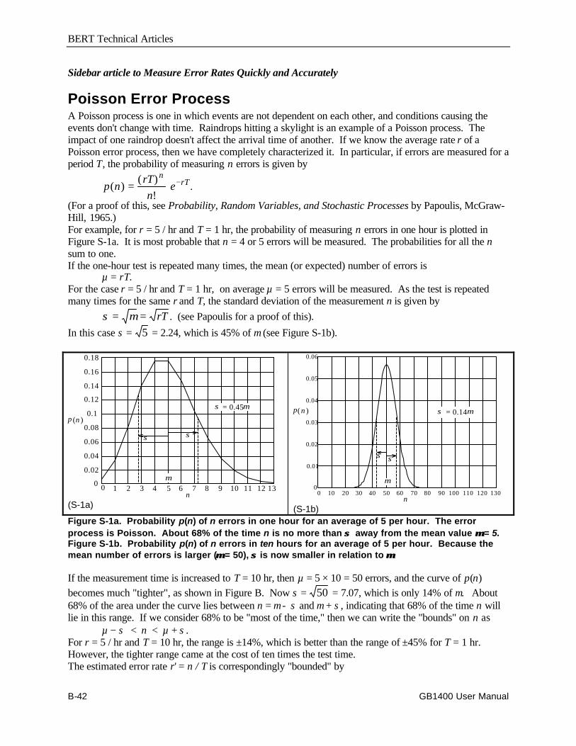
BERT Technical Articles
B-42 GB1400 User Manual
Sidebar article to Measure Error Rates Quickly and Accurately
Poisson Error ProcessA Poisson process is one in which events are not dependent on each other, and conditions causing theevents don't change with time. Raindrops hitting a skylight is an example of a Poisson process. Theimpact of one raindrop doesn't affect the arrival time of another. If we know the average rate r of aPoisson error process, then we have completely characterized it. In particular, if errors are measured for aperiod T, the probability of measuring n errors is given by
p nrT
ne
nrT( )
( )
!= − .
(For a proof of this, see Probability, Random Variables, and Stochastic Processes by Papoulis, McGraw-Hill, 1965.)For example, for r = 5 / hr and T = 1 hr, the probability of measuring n errors in one hour is plotted inFigure S-1a. It is most probable that n = 4 or 5 errors will be measured. The probabilities for all the nsum to one.If the one-hour test is repeated many times, the mean (or expected) number of errors is
µ = rT.For the case r = 5 / hr and T = 1 hr, on average µ = 5 errors will be measured. As the test is repeatedmany times for the same r and T, the standard deviation of the measurement n is given by
σ µ= = rT . (see Papoulis for a proof of this).
In this case σ = 5 = 2.24, which is 45% of µ (see Figure S-1b).
0 1 2 3 4 5 6 7 8 9 10 11 12 130
0.02
0.04
0.06
0.08
0.1
0.12
0.14
0.16
0.18
p ( )n
n
µ
σσ
σ = 0.45µ
(S-1a)0 10 20 30 40 50 60 70 80 90 100 110 120 130
0
0.01
0.02
0.03
0.04
0.05
0.06
p( )n
n
σ
µ
= 0.14σ µ
σ
(S-1b)Figure S-1a. Probability p(n) of n errors in one hour for an average of 5 per hour. The errorprocess is Poisson. About 68% of the time n is no more than σ σ away from the mean value µµ = 5.Figure S-1b. Probability p(n) of n errors in ten hours for an average of 5 per hour. Because themean number of errors is larger (µµ = 50), σσ is now smaller in relation to µµ.
If the measurement time is increased to T = 10 hr, then µ = 5 × 10 = 50 errors, and the curve of p(n)becomes much "tighter", as shown in Figure B. Now σ = 50 = 7.07, which is only 14% of µ. About68% of the area under the curve lies between n = µ − σ and µ + σ, indicating that 68% of the time n willlie in this range. If we consider 68% to be "most of the time," then we can write the "bounds" on n as
µ − σ < n < µ + σ.For r = 5 / hr and T = 10 hr, the range is ±14%, which is better than the range of ±45% for T = 1 hr.However, the tighter range came at the cost of ten times the test time.The estimated error rate r' = n / T is correspondingly "bounded" by

BERT Technical Articles
GB1400 User Manual B-43
(µ − σ) / T < r' < (µ + σ) / Tor
r r T r r r T− < < +/ ' / .These two "bounds" are shown by the two curves in Figure S-2. The measured error rate r' is seen to liebetween them most of the time. As T increases, the bounds get closer to r = 5 / hr, but there will alwaysbe some deviation of r' from r. Therefore the "actual" error rate r can never be known in practice; itwould take an infinite time to measure r.
The standard deviation of the error measurement n is σ µ= = rT . But since µ and r can't be knownexactly in practice, we must use the estimates µ ≈ n and r ≈ r' to get the estimate
σ ≈ =n r T' .
10 16
1014
1012
1010
109
108
107
106
105
BER
Attenuation (dB)
102
103
104
111098765432100 0.5 1 1.5 2 2.5 3 3.5 4 4.5 5 5.5
(elec)(opt)
Figure S-2. Specially distorted scale so plots of BER versus signal Attenuation (electrical oroptical) are straight lines (parallel to the dashed lines) when the noise is Gaussian.=============

BERT Technical Articles
B-44 GB1400 User Manual
Biography
Dan Wolaver is director of research and development at Tektronix/BTT, Inc. He received a PhD inelectrical engineering from MIT in 1969. For ten years he worked for Bell Labs on digitalcommunications systems, and he taught at Worcester Polytechnic Institute for eleven years. He is theauthor of Phase-Locked Loop Circuit Design.
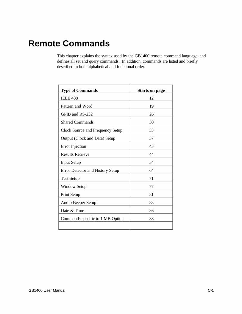
GB1400 User Manual C-1
Remote CommandsThis chapter explains the syntax used by the GB1400 remote command language, anddefines all set and query commands. In addition, commands are listed and brieflydescribed in both alphabetical and functional order.
Type of Commands Starts on page
IEEE 488 12
Pattern and Word 19
GPIB and RS-232 26
Shared Commands 30
Clock Source and Frequency Setup 33
Output (Clock and Data) Setup 37
Error Injection 43
Results Retrieve 44
Input Setup 54
Error Detector and History Setup 64
Test Setup 71
Window Setup 77
Print Setup 81
Audio Beeper Setup 83
Date & Time 86
Commands specific to 1 MB Option 88

Remote Commands
C-2 GB1400 User Manual
Overview
This section defines the GB1400 command syntax including command types, parametertypes, delimiters used between command elements, and terminators used at the end ofcommand lines.
SymbolsThe table below shows the symbols used in this chapter to describe GB1400 commandsand responses.
Symbol Meaning
<CR> Carriage return (ASCII decimal 13).
<LF> Line Feed (ASCII decimal 10).
<EOI> End or Identify, a message terminator signal specifiedin ANSI/IEEE Std. 488.2-1987
<ui> Unsigned integer in range 0 through 65,535
<NR1> Signed integer value.
<NR2> Floating point value, without an exponent.
<NR3> Floating point value, with an exponent.
<non-decimal numeric> A non-decimal integer in the range 0 - 255 (decimal)with leading "#H" (hexadecimal), "#Q" (octal), or "#B"(binary). Examples: Hexadecimal: #HFF Octal: #Q377 Binary: #B11111111
<qstring> A quoted string; that is a character string withbeginning and ending quotes.
[ ] Enclosed argument is required.
| Exclusive OR. For example the argument [a | b | c]means that you must include one and only one of thefollowing parameters: a, b, or c.
Remote Commands
GB1400 User Manual C-3
Command Types: Set and QueryThere two basic types of GB1400 commands: set commands and query commands. Setcommands are used to make setup changes or to cause a status change, for example tostart or stop a test. Query commands ask the instrument to respond with the contents ofa status register or the value of a given setup parameter.
GB1400 commands may have only a query form or only a set form, however mostcommands have both. When a command has both a set and query form, the name or"mnemonic" used for the query form will be identical to its corresponding set commandform, except for an added "?". For example the following are the mnemonics for the setand query form of the data threshold command:
q DATA_THRES (set command)
q DATA_THRES? (query command)
Note that in this User's Guide, query commands may be referred to as simply "queries",while set commands may be referred to as simply "commands".
Command Line Format
Command Names (Headers)
Every GB1400 command starts with a command header. Headers are character stringsthat contain either an entire command name, or a legal abbreviation of a command name.Legal command name abbreviations must include the leading significant characters in thecommand name. For example, in the save_word command only the first two letters aresignificant. Therefore the save_word command header may contain any of the followingcharacter strings:
save_wordsave_worsave_wosave_wsave_savesavsa
The minimum abbreviation for each command name is identified in the CommandDescriptions section later in this chapter. The use of command abbreviations is oftenuseful when you are operating a GB1400 Generator or Analyzer manually from aterminal. However when including command names in control programs it isrecommended that the full command names always be used as command headers. Thisimproves readability and reduces the chance that a control program will be incompatiblewith future versions of GB1400 software which may include additional commands.

Remote Commands
C-4 GB1400 User Manual
Command Line Rules
The following rules summarize the basic syntax of GB1400 commands:
Command Lines: A given command line may contain one or multiple commands. If acommand line contains multiple commands, commands will be separated by a ";"(semicolon).
Command Line Terminator
RS-232C Interface: Command lines issued to the instrument should be terminatedby a simple carriage return (CR). Responses generated by the instrument will beterminated as specified by the user in the RS-232 EOL menu function, that is CR, LF,CR/LF or LF/CR.
GPIB Interface: Command lines issued to the instrument can be terminated byeither EOI or EOI/LF. Responses generated by the instrument will be terminated asspecified by the user in the GPIB menu function, that is either EOI or EOI/LF.
Maximum Number of Characters per Line: Command lines may contain amaximum of 80 characters before the terminator.
Command Headers (Names): Each command must start with a header. This headermust contain either the full name of the command, or an abbreviation containing at least allof the leading significant characters identified for that command name. In addition, querycommands must end with a "?".
Upper and Lower Case: All characters in a GB1400 command line may be entered ineither upper or lower case.
Arguments: Commands may include one or more arguments (parameters) following theheader. The first argument following the header must be separated from the header byone or more blank characters (spaces). Subsequent arguments must be separated fromprevious parameters using commas.
Blank Characters (Spaces): One or more spaces are required between the commandheader and first parameter (if any). Otherwise spaces are ignored by the GB1400 andmay be used on a command line between headers, parameters, or required separators forreadability.

Remote Commands
GB1400 User Manual C-5
Setting Arguments Outside of Legal RangesIf you issue a set command with an argument value that is outside the allowed range forthat argument, then the instrument will reject the command.
Numeric ResponsesIf the response to a query command is a number, then it will be specified as one of thefollowing types:
Type Description
<NR1> decimal integer (e.g., 8)
<NR2> decimal real number without exponent (e.g., 2.00)
<NR3> decimal real number with exponent (e.g., 700.0E+6)
<Non-decimal numeric> non-decimal number with leading "#H" (hexadecimal), "#Q"(octal), or "#B" (binary).

Remote Commands
C-6 GB1400 User Manual
Command ExamplesThe following are some typical GB1400 set and query command examples:
Command Action or Response
clock_freq? Returns the current output clock frequency setup ofthe Generator or the measured input clock frequencyof the Analyzer
word_memory? Returns the saved word patterns in all 10 wordmemory locations.
word_memory? 7 Returns the saved word pattern in word memorylocation 7.
word memory 9, 16, #Haa, #H23 Sets the 16 bits of the word pattern stored at location9 to the bit sequence represented by AA23hexadecimal.
word_bits 8, #Q307 Sets the first eight bits of the current active pattern tothe bit sequence represented by 307 octal.
recall_word 7 Recalls the word pattern saved in location 7 andmakes it the current active pattern.
word_mem_len 6 , 16 Sets the length of the word pattern stored in location6 to 16 bits.
view_angle? Returns the current display view angle setup.
view_angle 3 Sets the view angle to 3.
rs_prompt "700" Sets the terminal display prompt to "700".
all_mem? Returns the word patterns saved in all 10 wordmemory locations.
Remote Commands
GB1400 User Manual C-7
Command Summary – Alphabetical
The following is a listing of all GB1400 Generator and Analyzer commands and the pagenumber of their full description.
Page
*cls ......................................................................................................C-12*ese [n]................................................................................................C-12*ese? ...................................................................................................C-13*esr?....................................................................................................C-13*idn?....................................................................................................C-13*lrn? ....................................................................................................C-14*opc.....................................................................................................C-14*opc?...................................................................................................C-14*rst ......................................................................................................C-15*sre [n] ................................................................................................C-15*sre?....................................................................................................C-16*stb? ....................................................................................................C-16*tst?.....................................................................................................C-17*wai.....................................................................................................C-17all_mem? .............................................................................................C-30amplitude [v] ........................................................................................C-37amplitude?............................................................................................C-37audio_rat_dn ........................................................................................C-83audio_rat_up ........................................................................................C-83audio_rate [v] .......................................................................................C-83audio_rate? ..........................................................................................C-84audio_vol [v] ........................................................................................C-84audio_vol? ............................................................................................C-84audio_vol_dn........................................................................................C-85audio_vol_up........................................................................................C-86auto_mode ...........................................................................................C-64auto_sample [n] ....................................................................................C-65auto_search [auto | off | disab]...............................................................C-63auto_search? ........................................................................................C-63auto_thresh [n] .....................................................................................C-66auto_width ..........................................................................................C-66byte_block [a], [i], [b1], ..., [bn] .............................................................C-89byte_block? [a].....................................................................................C-90byte_delete [a], [i] ................................................................................C-91byte_edit [a], [b1] .................................................................................C-92byte_edit? [a] .......................................................................................C-92byte_fill [i], [b1], [b2], ..., [bn]................................................................C-93byte_insert [a], [i], [b1], ..., [bn] .............................................................C-93byte_length [m], [n] ..............................................................................C-94

Remote Commands
C-8 GB1400 User Manual
byte_length? .........................................................................................C-94byte_mode ...........................................................................................C-95byte_sync [n] (Analyzer only)...............................................................C-96byte_sync? (Analyzer only) ................................................................C-96clock_amp_dn ......................................................................................C-37clock_amp_up ......................................................................................C-37clock_ampl [v]......................................................................................C-38clock_ampl? .........................................................................................C-38clock_freq [v].......................................................................................C-33clock_freq? ..........................................................................................C-33clock_freq? ..........................................................................................C-45clock_memory [m], [f] ..........................................................................C-34clock_memory? ....................................................................................C-33clock_memory? [m] ..............................................................................C-34clock_off_dn ........................................................................................C-38clock_off_up ........................................................................................C-38clock_offset [v] ....................................................................................C-39clock_offset?........................................................................................C-39clock_source [int|ext]............................................................................C-34clock_source? ......................................................................................C-34clock_step [v].......................................................................................C-35clock_step? ..........................................................................................C-35clock_stp_dn ........................................................................................C-35clock_stp_up ........................................................................................C-35clock_term [neg_2v | gnd | ac|pos_3v] ...................................................C-54clock_term? .........................................................................................C-54data_amp_dn........................................................................................C-39data_amp_up........................................................................................C-39data_ampl [v] .......................................................................................C-40data_ampl? ...........................................................................................C-40data_del_dn..........................................................................................C-55data_del_up..........................................................................................C-55data_delay [v] ......................................................................................C-56data_delay? ..........................................................................................C-56data_invert [on|off] ...............................................................................C-19data_invert? .........................................................................................C-19data_off_dn..........................................................................................C-40data_off_up..........................................................................................C-40data_offset [v]......................................................................................C-41data_offset? .........................................................................................C-41data_pattern [prbs | word | rdata]...........................................................C-19data_pattern? .......................................................................................C-20data_term [neg_2v | gnd | ac | pos_3v] ...................................................C-57data_term? ...........................................................................................C-57data_thr_dn..........................................................................................C-58data_thr_up..........................................................................................C-58data_thres ............................................................................................C-58data_thres? ..........................................................................................C-59
Remote Commands
GB1400 User Manual C-9
date ["yyyy-mm-dd"] .............................................................................C-86date?....................................................................................................C-86disp_select [total | window | test] ...........................................................C-67disp_select?..........................................................................................C-67edit_begin [n] .......................................................................................C-97edit_cntrl? ............................................................................................C-98edit_end [n] ..........................................................................................C-98error_rate [off|ext|rate_3|rate_4|rate_5|rate_6|rate_7] ............................C-43error_rate?...........................................................................................C-43error_reset...........................................................................................C-67error_single ..........................................................................................C-43gpib_address [v] ...................................................................................C-26gpib_address?.......................................................................................C-26gpib_bus [off_bus | talk_listen ] .............................................................C-26gpib_bus?.............................................................................................C-27header [on | off]....................................................................................C-31header?................................................................................................C-31histry_bits?...........................................................................................C-68histry_clear ..........................................................................................C-68histry_phase? .......................................................................................C-69histry_power?.......................................................................................C-69histry_stat?...........................................................................................C-69histry_sync? .........................................................................................C-70logo?....................................................................................................C-31offset [v] ..............................................................................................C-42offset? .................................................................................................C-42options?................................................................................................C-32prbs_length [v] .....................................................................................C-20prbs_length? .........................................................................................C-20print_enable [on|off]..............................................................................C-81print_enable?........................................................................................C-81print_port [ parallel | gpib | serial ] ..........................................................C-81print_port?............................................................................................C-82print_string ["s"]....................................................................................C-82rdata_del_dn ........................................................................................C-59rdata_del_up ........................................................................................C-59rdata_delay [v] .....................................................................................C-60rdata_delay?.........................................................................................C-60rdata_term [neg_2v | gnd | ac | pos_3v]..................................................C-60rdata_term?..........................................................................................C-60rdata_thr_dn.........................................................................................C-61rdata_thr_up.........................................................................................C-61rdata_thres [v]......................................................................................C-61rdata_thres? .........................................................................................C-62recall_freq [m] .....................................................................................C-36recall_mark [m1_8|m1_4|m1_2|m3_4|m7_8] ..........................................C-99recall_prom [n] ....................................................................................C-99
Remote Commands
C-10 GB1400 User Manual
recall_word [m] ....................................................................................C-21res_bits? ..............................................................................................C-45res_cur_rate?.......................................................................................C-45res_dm? ...............................................................................................C-46res_dm_per? ........................................................................................C-46res_efs?...............................................................................................C-46res_efs_per? ........................................................................................C-47res_elapsed? ........................................................................................C-47res_errors?...........................................................................................C-47res_es? ................................................................................................C-48res_es_per? .........................................................................................C-48res_los? ...............................................................................................C-48res_pha_es?.........................................................................................C-49res_ses?...............................................................................................C-49res_ses_per?........................................................................................C-49res_start? .............................................................................................C-50res_stop? .............................................................................................C-50res_sync?.............................................................................................C-50res_tes? ...............................................................................................C-51res_tes_per? ........................................................................................C-51res_tot_rate?........................................................................................C-51res_us? ................................................................................................C-52res_us_per? .........................................................................................C-52rs_echo [on|off]....................................................................................C-27rs_echo? ..............................................................................................C-27rs_pmt_lf [on|off] .................................................................................C-27rs_pmt_lf?............................................................................................C-28rs_prompt [s]........................................................................................C-28rs_xon_xoff [on|off]..............................................................................C-28rs_xon_xoff?........................................................................................C-29save_freq [m].......................................................................................C-36save_word [m] .....................................................................................C-21sync? ...................................................................................................C-70test_discard..........................................................................................C-71test_length [t] .......................................................................................C-71test_length? ..........................................................................................C-71test_mode [untimed|timed|repeat]...........................................................C-72test_mode?...........................................................................................C-72test_prev [current|previous]...................................................................C-72test_prev? ............................................................................................C-73test_print..............................................................................................C-73test_report [eot|on_error|both|none] ......................................................C-73test_report? ..........................................................................................C-74test_squelch [on|off] .............................................................................C-74test_squelch?........................................................................................C-74test_state [run|stop] ..............................................................................C-75test_state?............................................................................................C-75test_thres [v] ........................................................................................C-76
Remote Commands
GB1400 User Manual C-11
test_thres? ...........................................................................................C-76time [s] ................................................................................................C-87time?....................................................................................................C-87total_bits?.............................................................................................C-52total_error? ..........................................................................................C-53total_rate?............................................................................................C-53total_time? ...........................................................................................C-53tse [v] (Analyzer Only) ........................................................................C-17tse? (Analyzer Only) ............................................................................C-17tsr? (Analyzer Only) ............................................................................C-18view_angle [v]......................................................................................C-32view_angle? .........................................................................................C-32win_bit_len [v] .....................................................................................C-77win_bit_len? .........................................................................................C-77win_bits?..............................................................................................C-77win_error? ...........................................................................................C-77win_mode [bits|sec] ..............................................................................C-78win_mode?...........................................................................................C-78win_prev [current|previous]...................................................................C-78win_prev? ............................................................................................C-78win_rate?.............................................................................................C-79win_report [on|off]................................................................................C-79win_report? ..........................................................................................C-79win_sec_len [s] ....................................................................................C-80win_sec_len? .......................................................................................C-80win_time? ............................................................................................C-80word_bits [l], [b1 | b2] ...........................................................................C-21word_bits? ...........................................................................................C-22word_length [l] .....................................................................................C-22word_mem_len [m], [l] .........................................................................C-22word_mem_ord [m], [msb | lsb] .............................................................C-23word_mem_ord? ..................................................................................C-23word_mem_ord? [m] ............................................................................C-23word_memory [m], [l], [b1], [b2] ...........................................................C-24word_memory? [m] ..............................................................................C-24word_memory? ...................................................................................C-25word_order [msb | lsb] ..........................................................................C-25word_order?.........................................................................................C-25
Remote Commands
C-12 GB1400 User Manual
Command Descriptions
The following section defines each GB1400 set and query command. Unless notedotherwise, the following conventions will be followed in the command descriptions in latersections of this chapter:
Command Headers: Command headers will be shown using the entire command namein lower case. For legal abbreviations, see the Command Summary – Alphabeticalsection earlier in this Chapter.
Set and Query Command Pairs:
Commands that have both forms will be listed under the set command name. Forexample the data threshold set and query commands above will be listed under the nameDATA_THRES.
Common and Proprietary GPIB CommandsThe following GPIB "common commands" defined in ANSI/IEEE Std. 488.2-1987.
*cls
Clear Status. This set command clears the Standard Event Status Register (SESR) andthe event status bit (ESB) in the Status Byte Register (SBR). In addition it puts theinstrument into the Operation Complete Command Idle State and the Operation CompleteQuery Idle State.
Min. Abbr. *cls
Example *cls
*ese [n]
Event Status Enable. This command sets the Event Status Enable Register (ESER) tothe bit sequence corresponding to n, where n is a decimal number in the range 0 to 255.
Min. Abbr. *ese
Argument n: 0 to 255 decimal.
Example *ese 255(sets the ESER to 11111111 binary)
Remote Commands
GB1400 User Manual C-13
*ese?
Event Status Enable (Query). Returns a decimal number in the range 0 to 255corresponding to the contents of the Event Status Enable Register (ESER).
Min. Abbr. *ese?
Returns <NR1>where <NR1> is a decimal number from 0 to 255.
Example *ese? (command)255 (response)
*esr?
Event Status Register (Query) . Returns a decimal number in the range 0 to 255corresponding to the contents of the Standard Event Status Register (SESR).
Min. Abbr. *esr?
Returns <NR1>where <NR1> is a decimal number in the range 0 to 255.
Example *esr? (command)213 (response)
*idn?
Identify (Query). Returns the GB1400 Generator or Analyzer identification, includingcompany name, BERT model number, Generator or Analyzer identifier, and softwareversion number.
Min. Abbr. *idn?
Returns TEKTRONIX, BERT-1400 [RX|TX], 0, Vs.sswhere:
RX indicates AnalyzerTX indicates GeneratorVs.ss = software version number (e.g. V3.00).
Example *idn?(command)
TEKTRONIX, BERT-1400 RX, 0, V3.00, (response)
Remote Commands
C-14 GB1400 User Manual
*lrn?
Learn (Query). Returns a character string listing the instrument's current setup, exceptfor:
q information on the remote ports,
q calibration values,
q stored frequencies, or
q stored words
The returned string will consist of a series of commands (headers plus parameters).These commands may be stored by the controller and used to restore the instrument tothe same setup at a later time.
Min. Abbr. *lrn
Example: lrn? (command)AUDIO_RATE 4 (response) ....AUDIO_VOL 0AUTO_SEARCH AUTOBYTE_LENGTH 8,0....WIN_SEC_LEN "00:00:1"WORD_ORDER MSB
*opc
Operation Complete. This command will cause the OPC bit in the Standard EventStatus Register to be set to one. If the OPC bit is enabled, this will result in an SRQ.Thus, the *opc command can be issued after a group of setup commands to determinewhen all of the setup commands have been executed.
Min. Abbr. *opc
Example *opc
*opc?
Operation Complete (Query). This query command will cause the instrument to returnthe ASCII character for "1" when all previous commands and queries have beencompleted. Thus the *opc? command may be used to determine when the instrumenthas completed a group of commands.
Min. Abbr. *opc?
Example *opc? (command)1 (response) <NR1 Numeric>
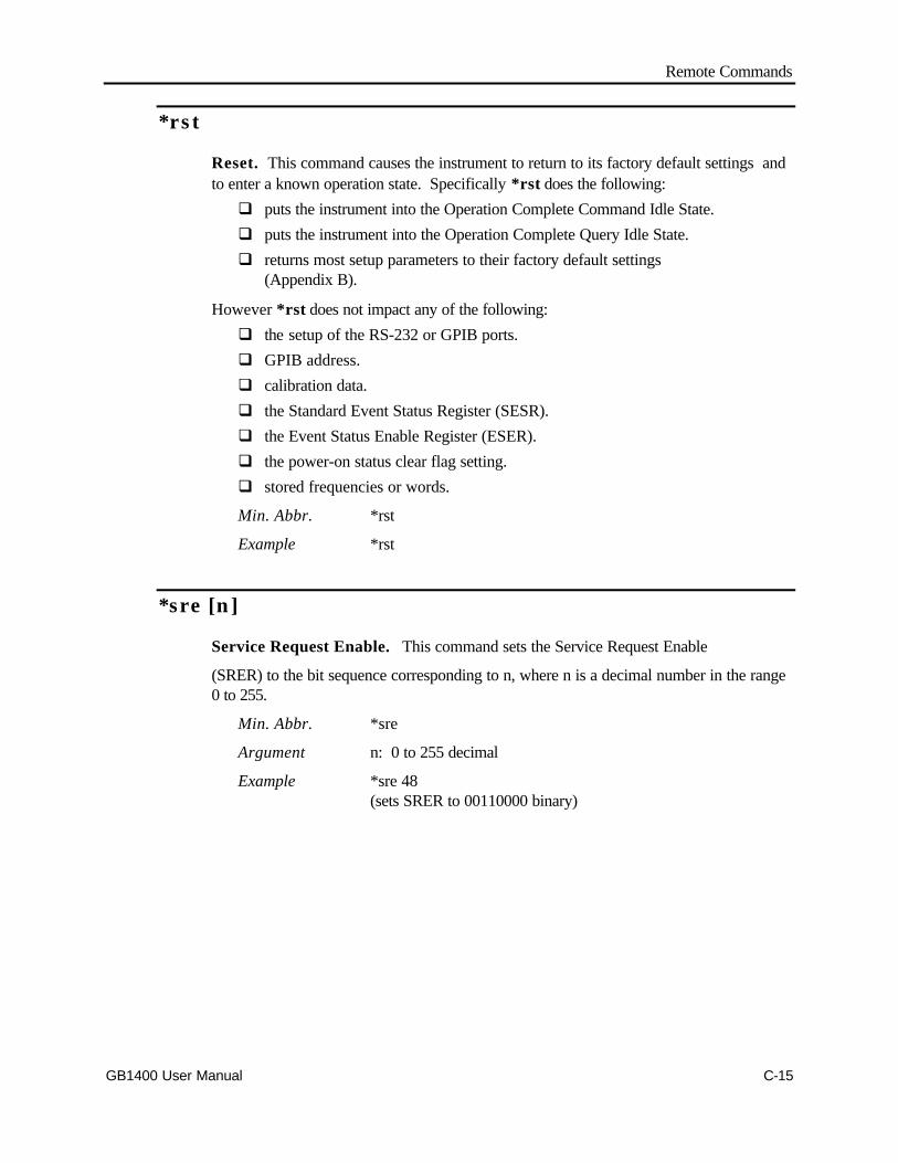
Remote Commands
GB1400 User Manual C-15
*rst
Reset. This command causes the instrument to return to its factory default settings andto enter a known operation state. Specifically *rst does the following:
q puts the instrument into the Operation Complete Command Idle State.
q puts the instrument into the Operation Complete Query Idle State.
q returns most setup parameters to their factory default settings(Appendix B).
However *rst does not impact any of the following:
q the setup of the RS-232 or GPIB ports.
q GPIB address.
q calibration data.
q the Standard Event Status Register (SESR).
q the Event Status Enable Register (ESER).
q the power-on status clear flag setting.
q stored frequencies or words.
Min. Abbr. *rst
Example *rst
*sre [n]
Service Request Enable. This command sets the Service Request Enable
(SRER) to the bit sequence corresponding to n, where n is a decimal number in the range0 to 255.
Min. Abbr. *sre
Argument n: 0 to 255 decimal
Example *sre 48(sets SRER to 00110000 binary)
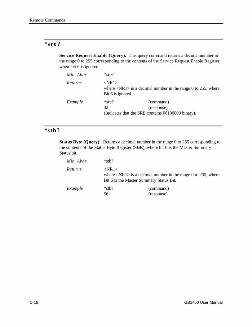
Remote Commands
C-16 GB1400 User Manual
*sre?
Service Request Enable (Query). This query command returns a decimal number inthe range 0 to 255 corresponding to the contents of the Service Request Enable Register,where bit 6 is ignored.
Min. Abbr. *sre?
Returns <NR1>where <NR1> is a decimal number in the range 0 to 255, whereBit 6 is ignored.
Example *sre? (command)32 (response)(Indicates that the SRE contains 00100000 binary).
*stb?
Status Byte (Query). Returns a decimal number in the range 0 to 255 corresponding tothe contents of the Status Byte Register (SBR), where bit 6 is the Master SummaryStatus bit.
Min. Abbr. *stb?
Returns <NR1>where <NR1> is a decimal number in the range 0 to 255, whereBit 6 is the Master Summary Status Bit.
Example *stb? (command)96 (response)

Remote Commands
GB1400 User Manual C-17
*tst?
Self Test. Causes the instrument to perform a self test and return the result. A result of0 means the self test was successful. A return of any other value means the self test wasnot successful. The GB1400 self test is limited in scope.
Min. Abbr. *tst?
Returns 0 (if successful)
Example *tst? (command)0 (indicates successful self test)
*wai
Wait. This command forces the instrument to stop processing any additional commandsuntil all pending operations are completed.
Min. Abbr. *wai
tse [v] (Analyzer Only)
Test Status Enable . This command sets the Test Status Enable Register to the bitsequence corresponding to v, where v is a decimal number in the range 0 to 255.
Min. Abbr. tse
Argument n: <NR1>, in the range 0 to 255.
Example tse 255(sets the TSR to 11111111 binary)
tse? (Analyzer Only)
Test Status Enable (Register) Query. This command returns a decimal numberrepresenting the current contents of the Test Status Enable Register (TSER).
Min. Abbr. tse?
Returns <NR1>, in the range 0 to 255.
Example tse? (command)TSE 255 (response)
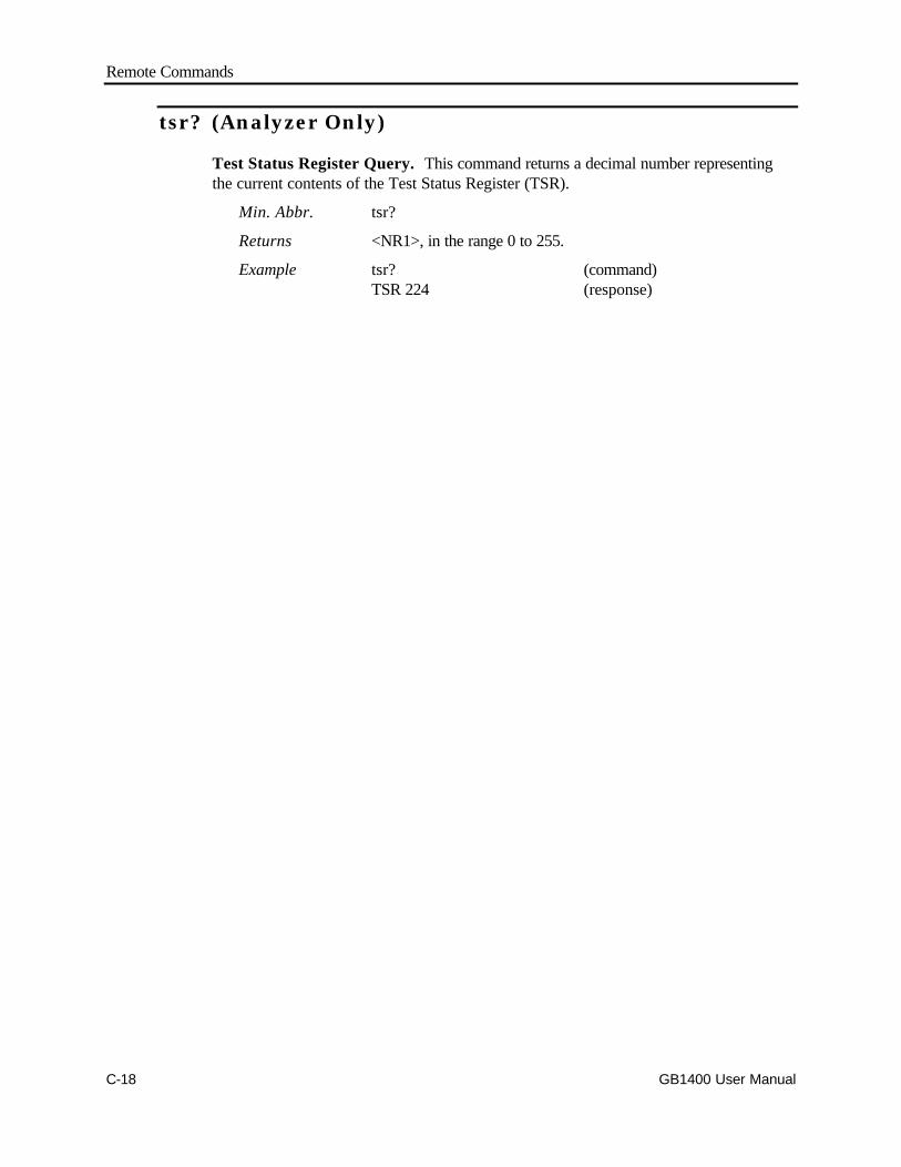
Remote Commands
C-18 GB1400 User Manual
tsr? (Analyzer Only)
Test Status Register Query. This command returns a decimal number representingthe current contents of the Test Status Register (TSR).
Min. Abbr. tsr?
Returns <NR1>, in the range 0 to 255.
Example tsr? (command)TSR 224 (response)
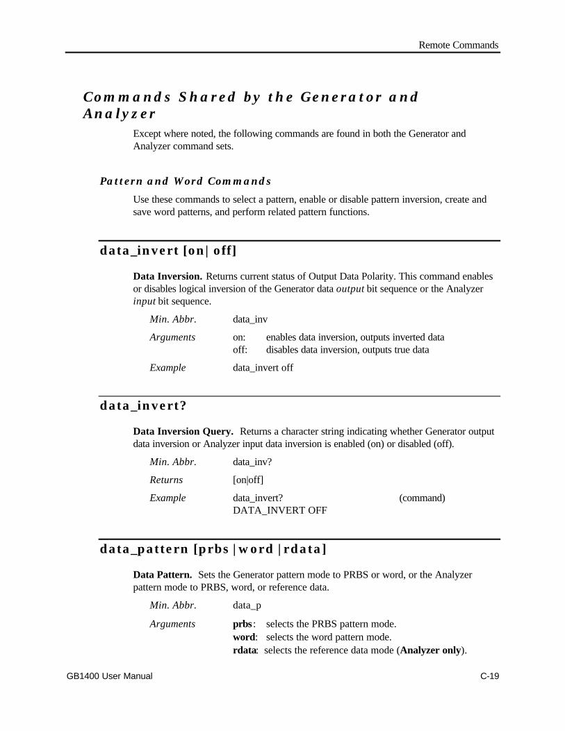
Remote Commands
GB1400 User Manual C-19
Commands Shared by the Generator andAnalyzer
Except where noted, the following commands are found in both the Generator andAnalyzer command sets.
Pattern and Word Commands
Use these commands to select a pattern, enable or disable pattern inversion, create andsave word patterns, and perform related pattern functions.
data_invert [on|off]
Data Inversion. Returns current status of Output Data Polarity. This command enablesor disables logical inversion of the Generator data output bit sequence or the Analyzerinput bit sequence.
Min. Abbr. data_inv
Arguments on: enables data inversion, outputs inverted dataoff: disables data inversion, outputs true data
Example data_invert off
data_invert?
Data Inversion Query. Returns a character string indicating whether Generator outputdata inversion or Analyzer input data inversion is enabled (on) or disabled (off).
Min. Abbr. data_inv?
Returns [on|off]
Example data_invert? (command)DATA_INVERT OFF
data_pattern [prbs | word | rdata]
Data Pattern. Sets the Generator pattern mode to PRBS or word, or the Analyzerpattern mode to PRBS, word, or reference data.
Min. Abbr. data_p
Arguments prbs : selects the PRBS pattern mode.word: selects the word pattern mode.rdata: selects the reference data mode (Analyzer only).
Remote Commands
C-20 GB1400 User Manual
Example data_pattern prbs
data_pattern?
Data Pattern Query. Returns a character string indicating the current Generator orAnalyzer data pattern mode.
Min. Abbr. data_p?
Returns [prbs|word] (Generator)[prbs|word|rdata] (Analyzer)
Example data_pattern? (command)DATA_PATTERN PRBS (response)
prbs_length [v]
PRBS Length. Selects the current PRBS pattern which becomes the current activepattern if and only if pattern "mode" is set to PRBS (see data_pattern command). Theargument [v] may be set to 7, 15, 17, 20, or 23 corresponding to the five PRBS patternsthat can be transmitted by the Generator and Analyzed by the Analyzer.
Min. Abbr. prb
Arguments 7: Selects the PRBS with a length of 27-1 bits.15: Selects the PRBS with a length of 215-1 bits.17: Selects the PRBS with a length of 217-1 bits.20: Selects the PRBS with a length of 220-1 bits.23: Selects the PRBS with a length of 223-1 bits.
Example prbs_length 23
prbs_length?
PRBS Length Query. Returns an integer n, where 2n-1 is the length of the current prbspattern.
Min. Abbr. prb
Returns <NR1> which may equal 7, 15, 17, 20, or 23.
Example prbs_length? (command)PRBS_LENGTH 23 (response)
Remote Commands
GB1400 User Manual C-21
recall_word [m]
Recall Word. Causes the instrument to recall the word pattern saved at location "m" andmake this pattern the current word pattern and the active pattern.
Min. Abbr. recall_w
Arguments m: 0, 1, ..., 9
Example recall_word 5
save_word [m]
Save Word. Causes the instrument to save the current word pattern to word memorylocation "m".
Min. Abbr. save_w
Arguments m: 0, 1, ..., 9
Example save_word 5
word_bits [l], [b1 | b2]
Word Bits. Returns the programmable WORD pattern. The response will contain thepattern length and data bytes. Sets current word length to l bits, and sets the current wordpattern to the bit sequence represented by b1 and b2.
Min. Abbr. word_b
Arguments l: 8 or 16.
b1: #00 to #FF (hexadecimal)#Q000 to #Q377 (octal)#B00000000 to #B11111111 (binary)
b2: same as b1. b2 is allowed only if l (length) is set to 16
Example word_bits 16, #B10101010, #B11110000

Remote Commands
C-22 GB1400 User Manual
word_bits?
Word Bits Query. The response will be in the form [n] [byte 1] [byte 2], where n iseither 8 or 16 (the current word length) and byte 1 and byte 2 are hex, octal, or binaryrepresentations of the first and second bytes in the pattern. Note that byte 2 will beincluded only if pattern length is 16.
Min. Abbr. word_b?
Returns <NR1>, <non-decimal numeric(s) >
Example word_bits? (command)WORD BITS 16, #HAA, #HF0 (response)
indicating that the current word length is 16 bits and the currentpattern is AAF0 hex.
word_length [l]
Word Length. Sets the current word pattern length to 8 or 16 bits.
Min. Abbr. word_l
Argument l: 8 or 16.
Example word_length 16
NOTE: There is no query form to the word_length command. However, you may usethe word_bits? query to read the current word length.
word_mem_len [m], [l]
Word Memory Length. Sets the length of the word pattern saved in location m to lbits.
Min. Abbr. word_mem_l
Arguments m: 0, 1, ..., 9l: 8 or 16.
Example word_mem_len 5, 16
(sets the length of word memory 5 to 16 bits)
NOTE: There is no query form to this command. However, you can use theword_memory? [m] query to read the length of the word saved at location m.
Remote Commands
GB1400 User Manual C-23
word_mem_ord [m], [msb | lsb]
Word Memory Order. Sets the bit order of the word saved at location m to either"msb" (most significant bit first) or "lsb" (least significant bit first).
Min. Abbr. word_mem_o
Arguments m: 0, 1, ..., 9msb: most significant bit firstlsb: least significant bit first
Example word_mem_ord 9, msb
(selects the most significant bit first order forword memory location 9)
word_mem_ord?
Word Memory Order Query (All). Returns a command string ("MSB" or "LSB")indicating the bit order of each of the 10 word memory locations.The response will consist of 10 message units, separated bysemi-colons ";" and will contain the memory location, and wordorder of each memory.
Min. Abbr. word_mem_o?
Returns <NR1>, [MSB|LSB]; <NR1> [MSB|LSB]; ... etc.
Example word_mem_ord? (command)WORD_MEM_ORD 0, LSB; (response)WORD_MEM_ORD 1 MSB;WORD_MEM_ORD 2 MSB;....
word_mem_ord? [m]
Word Memory Order Query. Returns a command string ("MSB" or "LSB")indicating the bit order of the word saved at location m.
Min. Abbr. word_mem_o
Arguments m: 0, 1, ..., 9
Returns "MSB" or "LSB"
Example word_mem_ord? 1 (command)WORD_MEM_ORD 1, LSB (response)
which indicates that the word order of word memory location 1 is"least significant bit first".

Remote Commands
C-24 GB1400 User Manual
word_memory [m], [l], [b1], [b2]
Word Memory. Stores into word memory m the word pattern of length l, with a bitsequence represented by b1 and b2.
Min. Abbr. word_memo
Arguments m: decimal in range 0 to 9.l: 8 or 16b1: #00 to #FF (hexadecimal)
#Q000 to #Q377 (octal)#B00000000 to #B11111111 (binary)
b2: same as b1. However, b2 is allowed only if l (length)is set to 16.
Example word_memory 3, 16, #HC4, #HF0
Stores the 16-bit sequence C4F0 (hex) into word memory 3.
word_memory? [m]
Word Memory Query. Returns the 8 or 16-bit pattern saved in word memory m in theform: [m], [byte 1], [byte 2], where m is either 8 or 16 (word length in bits), and byte 1and byte 2 are hex representations of the first and second bytes in the pattern. Note thatbyte 2 will be included only if pattern length is 16. word_memory? returns the contentsof all programmable WORD memories. The response will units separated by semi-colonsand will contain the memory location, length and data bytes of each memory.
Min. Abbr. word_memo?
Arguments m: 0 to 9
Returns <NR1>, <NR1>, <non-decimal numeric(s)>
Example word_memory? 4 (command)WORD_MEMORY 4, #H87, #H76 (response)
Remote Commands
GB1400 User Manual C-25
word_order [msb | lsb]
Word Order. Sets the bit order of the current word to MSB or LSB. The unit will startthe transmission with the MSB of the first byte or the LSB of the first byte (MSB/LSB).After the MSB (or LSB), the bits would be transmitted continuing with the bits of the firstbyte until the LSB (or MSB) is reached, then proceeding with the next byte in the sameorder.
Min. Abbr. word_o
Arguments msb: most significant bit firstlsb: least significant bit first.
Example word_order lsb
Note: On changing the WORD ORDER, the new setting is effective only on patternbytes edited after the change. If the ORDER is changed in the middle of programmingpattern bytes, the bytes programmed prior to the ORDER change will be reversed fromthose programmed after the change.
For example, if the WORD ORDER was previously LSB in memory 6, and the datapattern is programmed as follows:
edit_begin 6
byte_length 4,0
byte_block 0,16,#HAA,#HAA
word_order MSB
byte_block 2,16,#HAA,#HAA
edit_end 6
The pattern would become #H55, #H55, #HAA, #HAA.
Example #1 - To download a 32,768-byte pattern to memory location 1 without affectingthe current 256K pattern.
edit_begin 1
word_order msb
byte_length 32768,0
byte_block 0,80,#H00,#H01,#H02,#H03,#H04,#H05,#H06,#H07,#H08,#H09
byte_block 10,80,#H00,#H01,#H02,#H03,#H04,#H05,#H06,#H07,#H08,#H09
.
.
.
byte_block 32750,80,#H00,#H01,#H02,#H03,#H04,#H05,#H06,#H07,#H08,#H09
byte_block 32760,64,#H00,#H01,#H02,#H03,#H04,#H05,#H06,#H07
Remote Commands
C-26 GB1400 User Manual
edit_end 1
Example #2 - To edit memory location 6 and save into memory location 8 withoutaffecting the current pattern or location 6.
edit_begin 6
word_order msb
byte_block 12,16,#H24,#H23
edit_end 8
If the data pattern to be programmed is not of the same WORD ORDER as thatassociated with the pattern memory location being used, the WORD ORDER must bespecified prior to any editing or downloading.
Example #3 - To select 512K word mode and have a particular stored pattern withdifferent current pattern.
byte_mode 512
edit_begin -1
word_order msb
byte_length 65536,0
byte_fill 48,#H00,#H22#H44,#H66,#H88,#HAA
edit_end -1
save_word 0
edit_begin -1
word_order lsb
byte_len 48600,0
byte_fill 8,#HAA
byte_block 0,72,#HF6,#HF6,#HF6,#H28,#H28,#H28,#H01,#H02,#H03
.
.
.
edit_end -1
Remote Commands
GB1400 User Manual C-27
When changing the BUFFER MODE, the stored patterns and the current pattern may belost. When transitioning from a smaller mode to a larger mode, some of the storedpatterns will be lost. When going from larger to smaller, those patterns (including thecurrent pattern) which have lengths greater than the allowed length will be initialized.
Memory allocation for Word Memory storage
1M ………………………….. **
512K WORD0…………………………….
256k WORD0………….WORD1………..WORD2…….
128k WORD0..WORD1..WORD2..WORD3..WORD4..WORD5..
64K 0.. 1.. 2.. 3.. 4.. 5.. 6.. 7.. 8.. 9..
** The 1M storage area is used only for the current WORD pattern.
The chart above can be used to determine which stored patterns will be saved after aMODE transition and in which storage location it will be found. For example, ontransitions from 128K to 256K, the stored patterns 0, 2 and 4 of the 128K mode will befound at the 256K locations 0, 1, and 2 respectively, while the stored patterns at 1, 3 and 5of the 128K will be lost.
On switching to a smaller MODE, only when the pattern in the storage area has a lengthgreater than the new allowed length, will be lost. (Except for 128K to 64K, whereWORD5 will always be lost).
word_order?
Word Order Query. Returns WORD transmission order. Returns a character string(MSB or LSB) indicating the bit order of the current word.
Min. Abbr. word_o?
Response "MSB" or "LSB"
Example word_order? (command)WORD_ORDER LSB (response)

Remote Commands
C-28 GB1400 User Manual
word_memory?
Word Memory Query. Returns the all ten programmable WORD memories. Theresponse will be ten message units separated by semi-colons ";", and each will contain thememory location, length and data bytes of each memory.
Response <NR1 Numeric>
<NR2 Numeric>
<non-decimal numeric(s)>
Remote Commands
GB1400 User Manual C-29
GPIB and RS-232 Commands
gpib_address [v]
GPIB Address. This command sets the instrument's GPIB address to v. It may only beissued via the instrument's RS-232C port.
Min. Abbr. gpib_a
Arguments v: 0, 1, ..., 30.
Example gpib_address 15
gpib_address?
GPIB Address Query. This command returns a decimal number indicating theinstrument's GPIB address. It may only be issued over the RS-232C port.
Min. Abbr. gpib_a?
Returns <NR1>
Example gpib_address? (command)GPIB_ADDRESS 15 (response)
gpib_bus [off_bus || talk_listen ]
GPIB Bus Mode. This command sets the instrument's gpib bus mode. It may be usedonly over the RS-232C port.
Min. Abbr. gpib_b
Arguments off_bus : puts instrument in the gpib off-bus mode In this mode
it will not communicate over the GPIB.
talk_listen puts the instrument on-bus as a talker/listener.
Example gpib_bus talk_listen
Remote Commands
C-30 GB1400 User Manual
gpib_bus?
GPIB Bus Mode Query. Returns a character string indicating the current GPIB busmode. May be used only over the RS-232C port .
Min. Abbr. gpib_b?
Returns [off_bus | talk_listen]
Example gpib_bus? (command)GPIB_BUS TALK_LISTEN (response)
rs_echo [on|off]
RS-232C Echo. Enables or disables character echo on the RS-232C (serial) port.
Min. Abbr. rs_e
Arguments on: Enables ECHO mode, instrument will echo back eachcharacter received.
off: Disables ECHO mode, instrument will not echo receivedcharacters.
Example rs_echo on
rs_echo?
RS-232C Echo Query. Returns a character string indicating whether RS-232C portecho is enabled (ON) or disabled (OFF).
Min. Abbr. rs_e?
Returns [on|off]
Example rs_echo? (command)RS_ECHO OFF (response)
rs_pmt_lf [on|off]
RS-232C Prompt Line Feed. This command may be used to add the current RS-232Cend of line (EOL) terminator, that is CR, LF, CR+LF, or LF+CR, to the end of theprompt. This feature may be useful when operating the instrument under program controlvia a serial (RS-232) link.
Min. Abbr. rs_pm
Remote Commands
GB1400 User Manual C-31
Arguments on: EOL terminator added to end of prompt (OAH)off: no terminator added to prompt.
Example rs_pmt_lf on
rs_pmt_lf?
RS-232C Prompt Line Feed Query. Returns a character string indicating whetherRS-232C prompt line feed (OAH) is enabled (on) or disabled (off).
Min. Abbr. rs_pm
Returns [on|off]
Example rs_pmt_lf?RS_PMT_LF ON
rs_prompt [s]
RS-232C Prompt. This command sets the prompt on the RS-232C port to the characterstring contained in the quoted string s . This string will appear at the start of each new lineon a terminal display. Maximum length is 8 characters.
Min. Abbr. rs_pr
Arguments s: <qstring>, a character string inside double quotes
Example rs_prompt "GB-1400 >" (command)will change the prompt to: GB1400>
þ NOTE: This command may be issued with a null string ("") argument to disable the RS-232C prompt.
rs_xon_xoff [on|off]
RS-232C XON/XOFF. This command enables or disables XON/XOFF flow control onthe RS-232C port.
Min. Abbr. rs_x
Arguments on: enables XON/XOFF flow controloff: disables XON/XOFF flow control
Example rs_xon_xoff on
Remote Commands
C-32 GB1400 User Manual
rs_xon_xoff?
RS-232C Xon/Xoff Query. This command returns a character string indicating whetherRS-232C port Xon/Xoff flow control is enabled or disabled.
Min. Abbr. rs_x?
Returns [on|off]
Example rs_xon_xoff? (command)RS_XON_XOFF ON (response)

Remote Commands
GB1400 User Manual C-33
Misc. Shared Commands
all_mem?
All Memory (Generator). Returns a character string indicating the current Generatorclock source (INT or EXT), the contents of all 10 Generator frequency memories, and thecontents of all 10 Generator word memories.
Min. Abbr. all_?
Returns <string> <NR1>, <NR3><NR1>, <NR1>, <Non-decimal numerics>
Example all_mem? (command)CLOCK_SOURCE INT; (response)CLOCK_MEMORY 0, 500.000E+6;CLOCK_MEMORY 1, 550.000E+6;...CLOCK_MEM 9, 700.000E+6;WORD_MEMORY 0, 16, #HAA, #HBB;WORD_MEMORY 1, 8, #HF0;...WORD_MEMORY 9, 16, #HFF, #H00
All Memory (Analyzer). Returns the contents of all 10 Analyzer word memories.
Returns <NR1>, <NR1>, <Non-decimal numerics>
Example all_mem? (command)WORD_MEMORY 0, 8, #HFF; (response)WORD_MEMORY 1, 16, #HAA, #H00;....WORD_MEMORY 9, 8, #H00

Remote Commands
C-34 GB1400 User Manual
header [on || off]
Header. Tells the instrument whether or not to include headers (command names) inresponses.
Min. Abbr. he
Arguments on: include headersoff: do not include headers
Example header on
header?
Header Query. Returns a character string indicating the instrument's header status.
Min. Abbr. he?
Returns [on | off]
Example header? (command)HEADER ON (response)
logo?
Logo Query. Returns a character string showing the Generator or Analyzer "logo"including company name, BERT model number, Generator or Analyzer identifier, andsoftware version number. This command may be used only on the RS-232C port. Usethe *idn? query to get this same information over the GPIB port.
Min. Abbr. l?
Returns **** TEKTRONIX BERT-1400 [RX|TX] Vs.ss mm/yywhere:
RX indicates AnalyzerTX indicates GeneratorVs.ss = software version number (e.g. V3.00)mm/yy = software revision month and year.
Example logo?**** TEKTRONIX BERT-1400 RX V3.00 10/93
Remote Commands
GB1400 User Manual C-35
options?
Options Query. Returns a character string listing all of the options installed in theinstrument, or returns the character string NONE indicating that no options are installed.
Min. Abbr. op?
Returns <string> , <string> , etc. where possible strings are:1 MB Indicates 1 MB Option installedPROM Indicates PROM Option installed75 OHM Indicates 75 ohm Option installedBURST Indicates BURST Mode installedPECL Indicates PECL Mode installed.NONE Indicates no options are installed.
Examples options? (command)OPTIONS NONE (response)
options? (command)OPTIONS 1 MB, PROM, 75 OHM, (response) BURST, PECL
options? (command)OPTIONS 1 MB (response)
view_angle [v]
View Angle. This command sets the LCD display viewing angle to "v".
Min. Abbr. v
Arguments v <NR1>, may equal 0 (lowest), 1, 2, or 3.
Example view_angle 2
view_angle?
View Angle Query. Returns a decimal number indicating the current LCD display viewangle setup.
Min. Abbr. v?
Returns <NR1>
Example view_angle?VIEW_ANGLE 2

Remote Commands
C-36 GB1400 User Manual
Generator CommandsThe following commands are found only in the Generator command set.
Clock Source and Frequency Setup Commands
clock_freq [v]
Clock Frequency. Sets the clock frequency to a value [v], specified in Hz, over therange of 1 MHz to 1405 MHz in steps of 1kHz.
Min. Abbr. clock_f
Arguments v <NR3>, in the range 1.000E+6 to 1405.000E+6 in stepsof 0.001E+6.
Example clock_freq 622.000E+6.
clock_freq?
Clock Frequency Query. Returns the current Generator clock frequency setting.
Min. Abbr. clock_f
Returns <NR3>
Example clock_freq? (command)CLOCK_FREQ 0.150E+6 (response)
clock_memory?
Clock Memory Query. Returns the contents of all ten frequency memory locations.The response will be 10 message units separated by semi-colons ";", and will contain thememory location and frequency.
Returns <NR1 Numeric>
<NR3 Numeric>

Remote Commands
GB1400 User Manual C-37
clock_memory [m], [f]
Clock Memory. Sets the frequency saved at frequency memory location [m] to aspecified value [f], in the range 1 MHz to 1405 MHz, in steps of 1 kHz.
Min. Abbr. clock_m
Arguments m: <NR1>, in the range 0, 1, ..., 9f: <NR3>, in the range 1.000E+6 to 1405.000E+6 in stepsof 0.001E+6
Example clock_memory 9, 100.000E+6
clock_memory? [m]
Clock Memory Query. Returns the frequency saved at frequency memory location[m]. The response will contain the memory location and the frequency.
Min. Abbr. clock_m?
Returns m <NR1>, <NR3>, in the range 0-9
Example clock_memory? 4 (command)CLOCK_MEMORY 4, 100.000E+6 (response)
clock_source [int|ext]
Clock Source. Sets the clock mode of the Generator to either internal (int) or external(ext).
Min. Abbr. clock_so
Arguments int Selects the internal clock sourceext Selects the external clock source.
Example clock_source int
clock_source?
Clock Source Query. Returns a character string indicating the current Generator clockmode.
Min. Abbr. clock_so?
Returns [int|ext]
Example clock_source? (command)CLOCK_SOURCE INT (response)

Remote Commands
C-38 GB1400 User Manual
clock_step [v]
Clock Step. Sets the clock frequency increment/decrement default step size 10 kHz,100 kHz, 1 MHz, 10 MHz, 100 MHz, or 1000 MHz.
Min. Abbr. clock_ste
Arguments v: <NR3>, in the range: 0.010E+6, 0.100E+6,1.000E+6, 10.000E+6, 100.000E+6 or 1000.000E+6
Example clock_step 1.000E+6
clock_step?
Clock Step Query. Returns the current clock frequency step size.
Min. Abbr. clock_ste?
Returns <NR3>
Example clock_step? (command)CLOCK_STEP 1.000E+6 (response)
clock_stp_up and clock_stp_dn
Clock Step Up, Clock Step Down. This command pair is used to increment ordecrement the current Generator frequency using the step size previously defined with theclock_step command.
Min. Abbr. clock_stp_uclock_stp_d
Arguments none
Example clock_step_upclock_step_dn
clock_stp_up [v] and clock_stp_dn [v]
Clock Step Up, Clock Step Down. This command pair is used to increment ordecrement the current clock frequency by v, which can range from: 0.1 MHz to 1405MHz, in 0.01 MHz steps.
Min. Abbr. clock_stp_uclock_stp_d
Arguments v: <NR3>, in the range 0.100E+6 to 1405.000E+6.
Example clock_step_up 0.100E+6clock_step_dn 0.100E+6
Remote Commands
GB1400 User Manual C-39
recall_freq [m]
Recall Frequency. This command recalls a previously saved frequency from memorylocation [m]. The recalled frequency becomes the current frequency of the Generatorinternal clock.
Min. Abbr. recall_f
Arguments m: <NR1>, in the range 0, 1, ..., 9.
Example recall_freq 5
save_freq [m]
Save Frequency. This command saves the current Generator internal clock frequencyto memory location [m],
Min. Abbr. save_f
Arguments m: <NR1>, in the range 0, 1, ..., 9.
Example save_freq 8

Remote Commands
C-40 GB1400 User Manual
Output (Clock and Data) Setup Commands
amplitude [v]
Amplitude. This command sets both Data and Clock amplitudes to the same voltage [v].
Min. Abbr. am
Arguments v: <NR2>, in the range 0.50 to 2.00 in steps of 0.05.
Example amplitude 1.50
amplitude?
Amplitude Query. Returns two message units, the first indicating the clockamplitude setting and the second indicating the data amplitude setting.
Min. Abbr. am?
Returns <NR2>, <NR2>
Example amplitude?(command)
CLOCK_AMPL 1.450; DATA_AMPL 1.450 (response)
clock_amp_up andclock_amp_dn
Clock Amplitude Up/Down (Default). This command pair is used to increment ordecrement the current clock amplitude setting by the default increment of 0.05 volts.
Min. Abbr. clock_amp_uclock_amp_d
Arguments none
Example clock_amp_upclock_amp_dn
Remote Commands
GB1400 User Manual C-41
clock_amp_up [v] andclock_amp_dn [v]
Clock Amplitude Up/Down. This command pair is used to increment or decrement thecurrent clock amplitude by specified amount of [v] volts.
Min. Abbr. clock_amp_uclock_amp_d
Arguments v: <NR2>, in range 0.05 to 1.50 in steps of 0.05.
Example clock_amp_up 0.05clock_amp_dn 0.05.
clock_ampl [v]
Clock Amplitude. This command sets the output clock amplitude to [v] volts.
Min. Abbr. clock_ampl
Arguments v <NR2>, in the range 0.50 to 2.00 in steps of 0.05
Example clock_amplitude 2.00
clock_ampl?
Clock Amplitude Query. Returns the current output clock amplitude setting.
Min. Abbr. clock_ampl?
Response: <NR2>
Example: clock_ampl? (command)CLOCK_AMPL 1.40
clock_off_up andclock_off_dn
Clock Offset Up, Clock Offset Down (Default). This command pair is used toincrement or decrement the current output clock signal baseline offset by a default valueof 0.05 volts.
Min. Abbr. clock_off_uclock_off_d
Arguments none
Remote Commands
C-42 GB1400 User Manual
Examples clock_off_upclock_off_dn
clock_off_up [v] andclock_off_dn [v]
Clock Offset Up, Clock Offset Down. This command pair is used to increment ordecrement the current output clock signal baseline offset by a specified amount [v] volts.
Min. Abbr. clock_off_uclock_off_d
Arguments v: <NR2>, in the range 0.05 to 3.00 in 0.05 v steps.
in the range 0.05 to 3.80 in 0.05 v steps (PECL option)
Example clock_off_up 0.10clock_off_dn 0.10
clock_offset [v]
Clock Offset. Sets the baseline offset of the output clock signal to [v] volts.
Min. Abbr. clock_offs
Arguments v: <NR2>, in the range -2.00 to 1.00 in steps of 0.05.
in the range -2.00 to 1.80 in 0.05 v steps (PECL option)
Example clock_offset -0.75
clock_offset?
Clock Offset Query. Returns the current value of the output clock signal baselineoffset.
Min. Abbr. clock_offs?
Returns <NR2>
Example clock_offset? (command)CLOCK_OFFSET -0.75 (response)
data_amp_up anddata_amp_dn
Data Amplitude Up/Down (Default). This command pair is used to increment ordecrement the current amplitude of the Generator data output by a default amount of 0.05volts.

Remote Commands
GB1400 User Manual C-43
Min. Abbr. data_amp_udata_amp_d
Arguments none
Example data_amp_dn
data_amp_up [v] anddata_amp_dn [v]
Data Amplitude Up, Data Amplitude Down. This command pair is used to incrementor decrement the current amplitude of the Generator data output by a specified step sizeof [v] volts.
Min. Abbr. data_amp_udata_amp_d
Arguments v: <NR2>, in the range 0.05 to 1.50, in steps of 0.05.
Example data_amp_up 1.00
data_ampl [v]
Data Amplitude. Sets the amplitude of the Generator's data output signal to [v] volts.
Min. Abbr. data_ampl
Arguments v: <NR2>, in the range 0.50 to 2.00 in steps of 0.05.
Example data_ampl 1.00
data_ampl?
Data Amplitude Query. Returns the current amplitude setup of the Generator's dataoutput signal.
Min. Abbr. data_ampl?
Returns <NR2>
Example data_ampl? (command)DATA_AMPL 1.00 (response)
data_off_up anddata_off_dn
Data Offset Up/Down (Default). This command pair is used to increment or decrementthe current baseline offset of the Generator data output by a default amount of 0.05 volts.
Remote Commands
C-44 GB1400 User Manual
Min. Abbr. data_off_udata_off_d
Arguments none
Example data_off_up
data_off_up [v] anddata_off_dn [v]
Data Offset Up, Data Offset Down. This command pair is used to increment ordecrement the current baseline offset of the Generator data output by a specified step sizeof [v] volts.
Min. Abbr. data_off_udata_off_d
Arguments v: <NR2>, in the range 0.05 to 3.00, in steps of 0.05.
in the range 0.05 to 3.80 in 0.05 v steps (PECL option)
Example data_off_up 0.20
data_offset [v]
Data Offset. Sets the baseline offset of the Generator data output to a specified value of[v] volts.
Min. Abbr. data_offs
Arguments v: <NR2>, in the range -2.00 to 1.00 in steps of 0.05.
in the range -2.00 to 1.80 in 0.05 v steps (PECL option)
Example data_offset -0.50
data_offset?
Data Offset Query. Returns the current baseline offset of the Generator data output interms of volts.
Min. Abbr. data_offs?
Returns <NR2>
Example data_offset? (command)DATA_OFFSET -0.50 (response)
Remote Commands
GB1400 User Manual C-45
offset [v]
Offset. This command sets the Generator clock and data baseline offset to the samespecified value of [v] volts.
Min. Abbr. off
Arguments v: <NR2>, in the range -2.00 to 1.00 in steps of 0.05.
in the range -2.00 to 1.80 in 0.05 v steps (PECL option)
Example offset 1.50
offset?
Offset Query. Returns two message units, the first containing the Generator clockoutput baseline offset and the second containing the Generator data output baselineoffset.
Min. Abbr. off
Returns <NR2>, <NR2>
Example offset? (command)CLOCK_OFFSET 1.500 (response)DATA_OFFSET 1.500
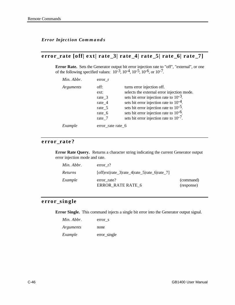
Remote Commands
C-46 GB1400 User Manual
Error Injection Commands
error_rate [off|ext|rate_3|rate_4|rate_5|rate_6|rate_7]
Error Rate. Sets the Generator output bit error injection rate to "off", "external", or oneof the following specified values: 10-3, 10-4, 10-5, 10-6, or 10-7.
Min. Abbr. error_r
Arguments off: turns error injection off.ext: selects the external error injection mode.rate_3 sets bit error injection rate to 10-3.rate_4 sets bit error injection rate to 10-4.rate_5 sets bit error injection rate to 10-5.rate_6 sets bit error injection rate to 10-6.rate_7 sets bit error injection rate to 10-7.
Example error_rate rate_6
error_rate?
Error Rate Query. Returns a character string indicating the current Generator outputerror injection mode and rate.
Min. Abbr. error_r?
Returns [off|ext|rate_3|rate_4|rate_5|rate_6|rate_7]
Example error_rate? (command)ERROR_RATE RATE_6 (response)
error_single
Error Single. This command injects a single bit error into the Generator output signal.
Min. Abbr. error_s
Arguments none
Example error_single

Remote Commands
GB1400 User Manual C-47
Analyzer CommandsThe following commands are found only in the Analyzer command set.
Results Retrieve Commands
Analyzer results commands are used to query the Analyzer for Test, Window, andTotalize interval results. Note that Analyzer numeric results are returned in one threebasic formats:.
q <NR1> or integer results, which include various counts such as bits or bit errors,up to a maximum of 16 digits. Examples: 0, 1, 15, 45959, 1234567890123456.Note that at a bit rate of 700 Mb/s, 16 digits can represent a bit count equivalentto over 165 days.
q <NR2> or "real number without exponent" results, such as percentages.Examples: 100.00. 99.99, 0.01, 0.00, 50.00, 27.83.
q <NR3> or "real numbers with exponent" results, such as BER, have threesignificant digits, with two places to the right of the decimal place, and a signedexponent following the letter "E". Examples: 1.00E-9, 9.99E-7, 2.08E-14.
þ NOTE: Returning Current or Previous Test Results. In response to queries for testinterval results, the Analyzer will return results from the current interval (so far), or fromthe previous interval, based on the following rules:
1. If the TEST PREV has been set to CURRENT and a test is in progress, then theinstrument will return results from the current test interval. A test is in progressafter TEST STATE is set to RUN, until the controller (or user) sets TESTSTATE to STOP, or the instrument automatically stops a test at the end of atimed test interval.
2. If TEST PREV has been set to PREVIOUS and there are previous resultsavailable, then the instrument will return results from the previous test interval.Previous results become available after TEST STATE has made at least oneRUN to STOP transition.
3. Otherwise, the Analyzer will not return results but instead will set the EXE bit (bit4) of the Standard Event Status Register (SESR).
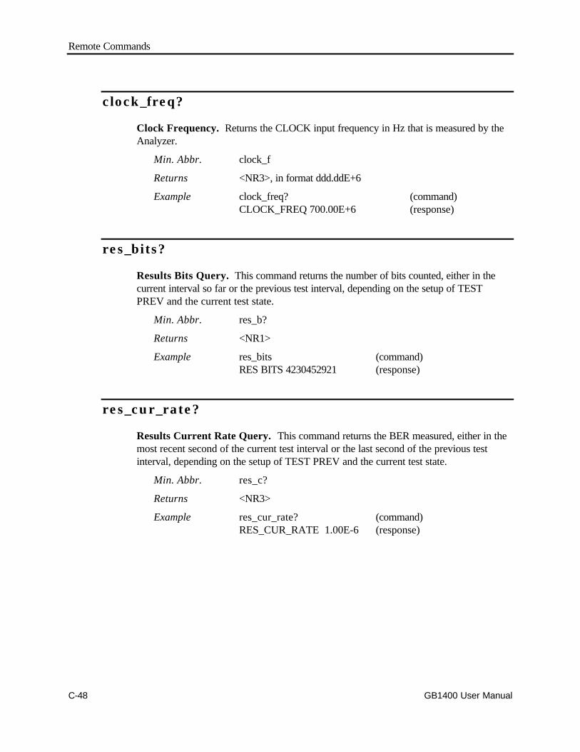
Remote Commands
C-48 GB1400 User Manual
clock_freq?
Clock Frequency. Returns the CLOCK input frequency in Hz that is measured by theAnalyzer.
Min. Abbr. clock_f
Returns <NR3>, in format ddd.ddE+6
Example clock_freq? (command)CLOCK_FREQ 700.00E+6 (response)
res_bits?
Results Bits Query. This command returns the number of bits counted, either in thecurrent interval so far or the previous test interval, depending on the setup of TESTPREV and the current test state.
Min. Abbr. res_b?
Returns <NR1>
Example res_bits (command)RES BITS 4230452921 (response)
res_cur_rate?
Results Current Rate Query. This command returns the BER measured, either in themost recent second of the current test interval or the last second of the previous testinterval, depending on the setup of TEST PREV and the current test state.
Min. Abbr. res_c?
Returns <NR3>
Example res_cur_rate? (command)RES_CUR_RATE 1.00E-6 (response)

Remote Commands
GB1400 User Manual C-49
res_dm?
Results Degraded Minutes Query. This command returns the number of degradedminutes counted, either in the current interval so far or in the previous test interval,depending on the setup of TEST PREV and the current test state.
Min. Abbr. res_dm?
Returns <NR1>
Example res_dm? (command)RES_DM 12 (response)
res_dm_per?
Results Degraded Minutes Query. This command returns the percentage ofdegraded minutes calculated, either in the current test interval so far or in the previous testinterval, depending on the setup of TEST PREV and the current test state.
Min. Abbr. res_dm_?
Returns <NR2>
Example res_dm_per? (command)RES_DM_PER 20.20 (response)
res_efs?
Results Error-Free Seconds. This command returns the number of error free secondscounted, either in the current test interval so far or in the previous test interval, dependingon the setup of TEST PREV and the current test state.
Min. Abbr. res_efs?
Returns <NR1>
Example res_efs? (command)RES_EFS 273 (response)

Remote Commands
C-50 GB1400 User Manual
res_efs_per?
Results Error-Free Seconds. This command returns the percentage of error freeseconds calculated, either in the current test interval so far or in the previous test interval,depending on the setup of TEST PREV and the current test state.
Min. Abbr. res_efs_?
Returns <NR2>
Example res_efs_per? (command)RES_EFS_PER 100.00 (response)
res_elapsed?
Results Elapsed (Time). This command returns a quoted string indicating the timeelapsed, either in the current interval so far or the previous interval, depending on thesetup of TEST PREV and the current test state.
Min. Abbr. res_el?
Returns <qstring>, in format "ddd-hh:mm:ss", where ddd = days, hh =hours, mm = minutes, and ss = seconds.
Example res_elapsed? (command)RES_ELAPSED "000-23:52:30"(response)
res_errors?
Results Errors. This command returns the total number of bit errors counted, either inthe current test interval so far or in the previous test interval, depending on the setup ofTEST PREV and the current test state.
Min. Abbr. res_er?
Returns <NR1>
Example res_errors? (command)RES_ERRORS 81252873 (response)
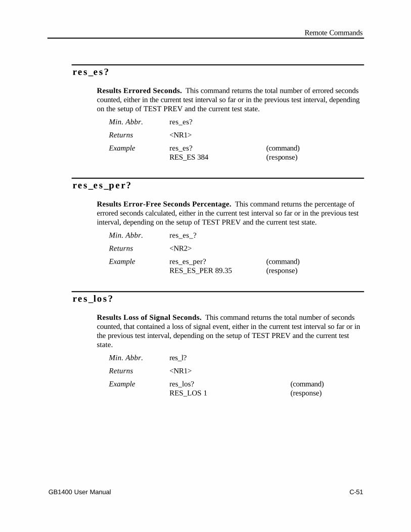
Remote Commands
GB1400 User Manual C-51
res_es?
Results Errored Seconds. This command returns the total number of errored secondscounted, either in the current test interval so far or in the previous test interval, dependingon the setup of TEST PREV and the current test state.
Min. Abbr. res_es?
Returns <NR1>
Example res_es? (command)RES_ES 384 (response)
res_es_per?
Results Error-Free Seconds Percentage. This command returns the percentage oferrored seconds calculated, either in the current test interval so far or in the previous testinterval, depending on the setup of TEST PREV and the current test state.
Min. Abbr. res_es_?
Returns <NR2>
Example res_es_per? (command)RES_ES_PER 89.35 (response)
res_los?
Results Loss of Signal Seconds. This command returns the total number of secondscounted, that contained a loss of signal event, either in the current test interval so far or inthe previous test interval, depending on the setup of TEST PREV and the current teststate.
Min. Abbr. res_l?
Returns <NR1>
Example res_los? (command)RES_LOS 1 (response)
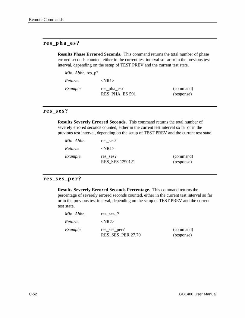
Remote Commands
C-52 GB1400 User Manual
res_pha_es?
Results Phase Errored Seconds. This command returns the total number of phaseerrored seconds counted, either in the current test interval so far or in the previous testinterval, depending on the setup of TEST PREV and the current test state.
Min. Abbr. res_p?
Returns <NR1>
Example res_pha_es? (command)RES_PHA_ES 591 (response)
res_ses?
Results Severely Errored Seconds. This command returns the total number ofseverely errored seconds counted, either in the current test interval so far or in theprevious test interval, depending on the setup of TEST PREV and the current test state.
Min. Abbr. res_ses?
Returns <NR1>
Example res_ses? (command)RES_SES 1290121 (response)
res_ses_per?
Results Severely Errored Seconds Percentage. This command returns thepercentage of severely errored seconds counted, either in the current test interval so faror in the previous test interval, depending on the setup of TEST PREV and the currenttest state.
Min. Abbr. res_ses_?
Returns <NR2>
Example res_ses_per? (command)RES_SES_PER 27.70 (response)
Remote Commands
GB1400 User Manual C-53
res_start?
Results Start (Time). This command returns a quoted string indicating the start time,either of the current test interval or the previous test interval, depending on the setup ofTEST PREV and the current test state.
Min. Abbr. res_sta?
Returns <qstring>, <qstring> in the format: yy/mm/dd
"hh:mm:ss.th" where yy = year, mmm = month (JAN, FEB, ...,DEC), dd = day, hh = hours, mm = minutes, ss = seconds, th =tenths and hundreds of seconds.
Example res_start? (command)RES_START "20/DEC/93, "14:00:00.00" (response)
res_stop?
Results Stop (Time). Returns a quoted string indicating the stop time of the previoustest interval. This command will produce a return if and only if previous results areavailable. Previous results become available after TEST STATE has made at least oneRUN to STOP transition.
Min. Abbr. res_sto?
Returns <qstring>, <qstring> in the format: yy/mm/dd
"hh:mm:ss.th" where yy = year, mmm = month (JAN, FEB, ...,DEC), dd = day, hh = hours, mm = minutes, ss = seconds, th =tenths and hundreds of seconds.
Example res_stop? (command)RES_STOP "20/DEC/93", "14:30:00.00" (response)
res_sync?
Results Synchronization Loss Seconds. This command returns the number ofseconds in which one or more pattern synchronization loss events occurred, either in thecurrent test interval so far or in the previous test interval, depending on the setup of TESTPREV and the current test state.
Min. Abbr. res_sy?
Returns <NR1>
Example res_sync? (command)RES_SYNC 23 (response)

Remote Commands
C-54 GB1400 User Manual
res_tes?
Results Threshold Errored Seconds. This command returns the total number ofthreshold errored seconds counted, either in the current test interval so far or in theprevious test interval, depending on the setup of TEST PREV and the current test state.
Min. Abbr. res_tes?
Returns <NR1>
Example res_tes? (command)RES_TES 9823 (response)
res_tes_per?
Results Threshold Errored Seconds Percentage. This command returns thepercentage of threshold errored seconds, either in the current test interval so far or in theprevious test interval, depending on the setup of TEST PREV and the current test state.
Min. Abbr. res_tes_?
Returns <NR2>
Example res_tes_per? (command)RES_TES_PER 5.52 (response)
res_tot_rate?
Results Total (Bit Error) Rate. This command returns the totalized error rate of theentire current test interval so far or of the entire previous test interval, depending on thesetup of TEST PREV and the current test state.
Min. Abbr. res_to?
Returns <NR3>
Example res_tot_rate? (command)RES_TOT_RATE 4.29E-7 (response)

Remote Commands
GB1400 User Manual C-55
res_us?
Results Unavailable Seconds. This command returns the total number of unavailableseconds counted, either in the current test interval so far or in the previous test interval,depending on the setup of TEST PREV and the current test state.
Min. Abbr. res_us?
Returns <NR1>
Example res_us? (command)RES_US 120 (response)
res_us_per?
Results Unavailable Seconds Percentage. This command returns the percentage ofunavailable seconds, either in the current test interval so far or in the previous test interval,depending on the setup of TEST PREV and the current test state.
Min. Abbr. res_us_?
Returns <NR2>
Example res_us_per? (command)RES_US_PER 29.01 (response)
total_bits?
Totalize Bits Query. Returns the total number of bits accumulated in the currentTotalize measurement interval. The Totalize bit count is zeroed at the start of each newTotalize measurement interval, that is at power-up and after each error reset.
Min. Abbr. total_b?
Returns <NR1>
Example total_bits? (command)TOTAL_BITS 32365018072 (response)
Remote Commands
C-56 GB1400 User Manual
total_error?
Totalize Error Query. Returns the number of bit errors counted so far in the currentTotalize measurement interval. The Totalize error count is zeroed at the start of eachnew Totalize measurement interval, that is at power-up and after a error reset.
Min. Abbr. total_e?
Returns <NR1>
Example total_error? (command)TOTAL_ERROR 20984 (response)
total_rate?
Totalize (Bit Error) Rate Query. Returns the bit error rate (BER) calculated so far inthe current Totalize measurement interval. Totalize BER equals the Totalize bit errorcount divided by the Totalize bit count. The number will reset at power-up and on errorreset.
Min. Abbr. total_r?
Returns <NR3>
Example total_rate? (command)TOTAL_RATE 8.62E-6 (response)
total_time?
Totalize Time Query. Returns a quoted string indicating the amount of timeaccumulated in the current Totalize measurement interval. Totalize time is zeroed at thestart of each new Totalize measurement interval, that is at power-up and after each errorreset.
Min. Abbr. total_t?
Returns <qstring>, in the format "ddd-hh:mm:ss" where ddd = days,hh = hours (00 ... 23), mm = minutes (00 ... 59), ss = seconds (00... 59)
Example total_time? (command)"000-12:34:56" (response)
Remote Commands
GB1400 User Manual C-57
Input Setup Commands
clock_term [neg_2v | gnd | ac]
Clock Termination. Sets the Analyzer clock input termination voltage to "v".
Min. Abbr. clock_ter
Arguments neg_2v 50 ohms to -2 volts.gnd 50 ohms to ground.ac 50 ohms via 0.01 µF capacitor to ground.Example clock_term gnd
clock_term?
Clock Termination Query. Returns a character string indicating the current Analyzerclock input termination setup voltage.
Min. Abbr. clock_ter?
Returns [neg_2v | gnd | ac ]
Example clock_term? (command)CLOCK_TERM GND (response)

Remote Commands
C-58 GB1400 User Manual
data_del_up anddata_del_dn
Data Delay Up/Down (Default). This command pair is used to increment (data_del_up)or decrement (data_del_dn) the current DATA input delay by the default amount, 0.005nSec.
Min. Abbr. data_del_udata_del_d
Argument none
Example data_del_updata_del_dn
Remote Commands
GB1400 User Manual C-59
data_del_up [v] anddata_del_dn [v]
Data Delay Up/Down. This command pair is used to increment (data_del_up) ordecrement (data_del_dn) the current DATA input delay by v seconds. Note that v isexpressed as a real number with an exponent and is in the range of 0.1 to 3.99 nSec in0.005 nSec steps.
Min. Abbr. data_del_udata_del_d
Argument v <NR3>, 0.1E-9 to 3.99E-9 in 0.005E-9 steps
Example data_del_up 0.02E-9data_del_dn 0.10E-9
data_delay [v]
Data Delay. Sets the Analyzer DATA input delay to any value from 0.0 nS to 3.99 nS in0.005 nSec steps. . Note that v is expressed as a real number with an exponent of -9.
Min. Abbr. data_dela
Argument v: 0.00E-9 to 3.99E-9 in 0.005E-9 steps
Example data_delay 1.62E-9
data_delay?
Data Delay Query. Returns the current value of the Analyzer DATA input delay setupparameter.
Min. Abbr. data_dela?
Returns <NR3>
Example data_delay? (command)DATA_DELAY 1.62E-9 (response)
Remote Commands
C-60 GB1400 User Manual
data_term [neg_2v | gnd | ac]
Data Termination. Sets the Analyzer data input termination voltage to "v".
Min. Abbr. data_te
Arguments neg_2v: 50 ohms to -2 volts.gnd 50 ohms to ground.ac 50 ohms via 0.01 µF capacitor to ground.Example data_term ac
data_term?
Data Termination Query. Returns a character string indicating the current Analyzerdata input termination setup.
Min. Abbr. data_te?
Returns [neg_2v | gnd | ac ]
Example data_term? (command)DATA_TERM AC (response)
Remote Commands
GB1400 User Manual C-61
data_thr_up anddata_thr_dn
Data Threshold Up/Down (Default). This pair of commands increments (data_thr_up)or decrements (data_thr_dn) the current Analyzer DATA input threshold by the defaultincrement of 0.05 volts.
Min. Abbr. data_thr_udata_thr_d
Arguments none
Examples data_thr_up (increments threshold by 0.05 volts)data_thr_dn (decrements threshold by 0.05 volts)
data_thr_up [v] anddata_thr_dn [v]
Data Threshold Up/Down. This pair of commands increments (data_thr_up) ordecrements (data_thr_dn) the current Analyzer DATA input threshold by an amount v.
Min. Abbr. data_thr_udata_thr_d
Arguments v: 0.05 to 2.50 in 0.05 V steps
Examples data_thr_up 0.10 (increments threshold by 0.1 volt)data_thr_dn 2.00 (decrements threshold by 2 volts)
data_thres [v]
Data Threshold. Sets the threshold voltage for the Analyzer DATA input to v, wherethe allowed range for v depends on the current DATA input termination.
Min. Abbr. data_thre
Arguments v: -1.50 to 1.00 in 0.05 v steps, for input terminations
GND, AC
-2.50 to 0.00 in 0.05 v steps, for input terminations -2V
Example data_thres -1.50
Remote Commands
C-62 GB1400 User Manual
data_thres?
Data Threshold Query. Returns the current threshold voltage for the Analyzer DATAinput.
Min. Abbr. data_thre?
Returns <NR2>
Example data_thres? (command)DATA_THRES -1.50 (response)
rdata_del_up andrdata_del_dn
Reference Data Delay Up/Down (Default). This command pair is used to increment(rdata_del_up) or decrement (rdata_del_dn) the current REF DATA delay by the defaultincrement of 0.1 nSec.
Min. Abbr. rdata_del_urdata_del_d
Arguments none
Examples rdata_del_uprdata_del_dn
rdata_del_up [v] andrdata_del_dn [v]
Reference Data Delay Up/Down. This command pair is used to increment(rdata_del_up) or decrement (rdata_del_dn) the current REF DATA delay by v, where vis in <NR3> format and may be set in the range 0.1 nSec to 3.99 nSec in 0.1 nSec steps.
Min. Abbr. rdata_del_urdata_del_d
Argument v: <NR3>, 0.10E-9 to 3.90E-9 in 0.10E-9 steps.
Examples rdata_del_up 1.00E-9
rdata_del_dn 1.00E-9

Remote Commands
GB1400 User Manual C-63
rdata_delay [v]
Reference Data Delay. Sets the Analyzer REF DATA input delay to v, where v maybe set in the range 0.0 nSec to 3.99 nSec in 0.1 or 0.2 nSec steps. v is expressed as areal number with an exponent of -9.
Min. Abbr. rdata_dela
Argument v: 0.00E-9 to 3.99E-9, in steps of 0.10E-9 or 0.2E-9
Example rdata_delay 1.10E-9
rdata_delay?
Reference Data Delay Query. Returns the current Analyzer REF DATA input delay.
Min. Abbr. rdata_dela?
Returns <NR3>
Example rdata_delay? (command)RDATA_DELAY 1.10E-9 (response)
rdata_term [neg_2v | gnd | ac]
Reference Data Termination. Sets the Analyzer REF DATA input termination.
Min. Abbr. rdata_te
Arguments neg_2v: 50 ohms to -2 volts.gnd 50 ohms to ground.ac 50 ohms via 0.01 µF capacitor to ground.Example rdata_term neg_2v
rdata_term?
Reference Data Termination Query. Returns a character string indicating the currentAnalyzer Reference Data Input termination setup.
Min. Abbr. rdata_te?
Returns [neg_2v | gnd | ac]
Example rdata_term? (command)RDATA_TERM NEG_2V (response)

Remote Commands
C-64 GB1400 User Manual
rdata_thr_up andrdata_thr_dn
Reference Data Threshold Up/Down (Default). This command pair is used toincrement (rdata_thr_up) or decrement (rdata_thr_dn) the current REF DATA thresholdby the default increment of 0.05 volts.
Min. Abbr. rdata_thr_urdata_thr_d
Argument none
Examples rdata_thr_up
rdata_thr_dn
rdata_thr_up [v] andrdata_thr_dn [v]
Reference Data Threshold Up/Down. This command pair is used to increment(rdata_thr_up) or decrement (rdata_thr_dn) the current REF DATA threshold by v,where v is in <NR2> format and may be set in the range 0.05 to 2.50 Volts in 0.05 Vsteps.
Min. Abbr. rdata_thr_urdata_thr_d
Argument v: <NR2>, 0.05 to 2.50 volts, in 0.05 V steps.
Examples rdata_thr_up 0.10
rdata_thr_dn 0.50
rdata_thres [v]
Reference Data Threshold. Sets the threshold voltage for the Analyzer REF DATAinput to v, where the allowed range for v depends on the current input clock termination.
Min. Abbr. rdata_thre
Arguments v: -1.50 to 1.00 in 0.05 v steps, for terminations
GND, AC
-2.50 to 0.00 in 0.05 v steps, for termination -2V
Example rdata_thres 1.00
Remote Commands
GB1400 User Manual C-65
rdata_thres?
Reference Data Threshold Query. Returns the current threshold voltage for theAnalyzer REF DATA input.
Min. Abbr. rdata_thre
Returns <NR2>
Example rdata_thres? (command)RDATA_THRES 1.00 (response)
Remote Commands
C-66 GB1400 User Manual
Error Detector and History Setup Commands
auto_search [auto | off | disab]
Auto_Search. Enables or disables the Auto Search and Automatic pattern re-alignmentfunctions.
Min. Abbr. auto_s
Arguments auto: Auto Search on, pattern re-alignment enabledoff: Auto Search off, pattern re-alignment enableddisab :Auto Search off, pattern re-alignment disabled
Example auto_search auto
auto_search?
Auto_Search Query. Returns a character string representing the current setup ofAUTO SEARCH and automatic pattern re-alignment.
Min. Abbr. auto_s?
Returns [auto | off | disable]
Example auto_search? (command)AUTO_SEARCH AUTO (response)
Remote Commands
GB1400 User Manual C-67
auto_mode [ber, fast]
Auto_Mode. Sets the Auto Search mode for finding the Data Delay.
Arguments ber: Uses the Bit Error Rate to find the Data Eye Crossing
fast Uses the Clock to Data Phase to quickly find the Data Crossing
Example auto_mode ber
auto_mode?
Returns the Auto Search Data Delay mode.
Response BER or FAST
Remote Commands
C-68 GB1400 User Manual
auto_sample [n]
Auto_Sample. Sets the number of Data Bits to Sample when Auto Search is in BERmode. This is the exponent for the number of Bits accumulated at the Delay Settings, interms of 10E+n:
Arguments n: 4 to 11
Example auto_sample 4
auto_sample?
Returns the exponent of the number of Data Delay Sampling Bits.
Response <NR1 Numeric>
Remote Commands
GB1400 User Manual C-69
auto_thresh [n]
Auto_Thresh. Sets the Error Rate Threshold used when Auto Search is in BER mode.This the exponent for the error rate used for the Delay settings, in terms of 10E-n
Arguments n: 3 to 10
Example auto_thresh 3
auto_thresh?
Returns the exponent of the number used as the Data Delay Error Rate Threshold.
Response <NR1 Numeric>
auto_width?
Returns the Width of the Data Eye as determined by Auto Search, in either mode. Thesevalues are in terms of seconds. (Example, 100E-12 is 100 pS.) The following delay errorcodes are returned if appropriate:
1 Only 1 Data Eye Crossing found
2 No Data Eye Crossing found
3 Auto Search not run
Response <NR1 Numeric>

Remote Commands
C-70 GB1400 User Manual
disp_select [total || window || test]
Display Select. Selects the total, window, or test display mode. The display modedetermines which BER and bit error results are shown in the top-middle, and top-rightfields respectively of the display.
Min. Abbr. dis
Arguments total: selects the Totalize display mode, Totalize ErrorRate/Totalwindow: selects the Window display mode, Window Error Rate/Totaltest: selects the Test display mode, Test Error Rate/Total
Example disp_select test
disp_select?
Display Select Query. Returns a character string that indicates the current displaymode of the Analyzer.
Min. Abbr. dis?
Returns [total | window | test]
Example disp_select? (command)DISP_SELECT TEST (response)
error_reset
Error Reset. This command resets the Totalize and Window measurement processes.This does not affect Test results.
Min. Abbr. er
Arguments none
Example error_reset

Remote Commands
GB1400 User Manual C-71
histry_bits?
History Bits Query. Returns a character string indicating the state of the BIT errorhistory indicator.
Min. Abbr. histry_b?
Returns [on | off]
Example histry_bits? (command)HISTRY_BITS OFF (response)
histry_clear
History Clear. This command clears (resets) all four Analyzer history LEDs: SyncLoss, Bit Error, Phase Error, and Power Loss.
Min. Abbr. histry_c
Arguments none
Example histry_clear
Remote Commands
C-72 GB1400 User Manual
histry_phase?
History Phase. Returns a character string indicating the state of the PHASE errorhistory indicator.
Min. Abbr. histry_ph?
Returns [on | off]
Example histry_phase? (command)HISTRY_PHASE ON (response)
histry_power?
History Power. Returns a character string indicating the state of the POWER Losshistory indicator.
Min. Abbr. histry_po?
Returns [on | off]
Example histry_power? (command)HISTORY_POWER OFF (response)
histry_stat?
History Status Query. This command returns a summary of the Analyzer's front panelstatus. The response will be in the form of multiple message units separated bysemicolons.
Min. Abbr. histry_st?
Returns Window error rate <NR3>Totalize error rate <NR3>Received clock frequency <NR3>Sync Lock status [on | off]History status indicators [on | off]
Example histry_stat (command)WIN_RATE 1.5E-03; (response)TOTAL_RATE 3.7E-06;CLOCK_FREQ 701.47E+6;SYNC OFF;HISTRY_SYNC ON;HISTRY_BITS ON;HISTRY_PHASE OFF;HISTRY_POWER OFF

Remote Commands
GB1400 User Manual C-73
histry_sync?
History Sync Indicator Query. Returns a character string indicating the state of theSYNC Loss history indicator.
Min. Abbr. histry_sy?
Returns [on | off]
Example histry_sync? (command)HISTRY_SYNC OFF (response)
sync?
Synchronization Query. Returns a character string indicating whether the Analyzersynchronization LOCK LED is on or off. If it is on, then the Analyzer is in patternsynchronization. If it is off, then the Analyzer is out of pattern synchronization.
Min. Abbr. sy?
Returns [on|off]
Example sync? (command)SYNC ON (response)
Remote Commands
C-74 GB1400 User Manual
TEST Setup Commands
test_discard
Test Discard. This command discards all results from the previous test interval, makingprevious results unavailable until the next test state RUN to STOP transition occurs.
Min. Abbr. test_d
Arguments none
Example test_discard
test_length [t]
Test Length. Sets the test length to the time specified in the string "s". The string will bein 24-hour format "HH:MM:SS" enclosed in single or double quotes. This command setsthe timed test interval. This interval will be in effect only when the test mode is timed orrepeat.
Min. Abbr. test_l
Arguments t <qstring>, in format "hh:mm:ss", where hh = hours(0 to 24) mm = minutes (0 to 59), ss = seconds (0 to 59).
Example test_length "02:00:00"
test_length?
Test Length Query. Returns the current value of the timed test length parameter.
Min. Abbr. test_l?
Returns <qstring>, in format "hh:mm:ss"
Example test_length? (command)TEST_LENGTH "02:00:00" (response)

Remote Commands
GB1400 User Manual C-75
test_mode [untimed|timed|repeat]
Test Mode. Sets the test timing mode. The test once started, will stop and startaccording to the mode.
Min. Abbr. test_m
Arguments untimed: after test start, a test interval will continue until a teststop command is received, or the test is stopped manually fromthe front panel, or power loss.timed: after a test start, a test interval will stop automaticallyafter test length has elapsed, front panel key, remote command orpower loss.repeat: after test start, a test interval will stop and then restartautomatically after test length has elapsed. This process willcontinue until a test stop command is received, or testing isstopped manually from the front panel, or by power loss.
Example test_mode timed
test_mode?
Test Mode Query. Returns the current Analyzer test timing mode.
Min. Abbr. test_m?
Returns [untimed|timed|repeat]
Example test_mode?TEST_MODE TIMED
test_prev [current|previous]
Test Previous. Sets test_prev parameter to "current" or "previous". This parameterdetermines whether responses to results query commands will be based on the currentinterval or the previous interval.
Min. Abbr. test_pre
Arguments current: Test status commands will return results from
the current test interval
previous : Test status commands will return results from
the previous test interval
Example test_prev current

Remote Commands
C-76 GB1400 User Manual
test_prev?
Test Previous Query. Returns the current state of the test_prev command.
Min. Abbr. test_pre?
Returns [current|previous]
Example test_prev? (command)TEST_PREV CURRENT (response)
test_print
Test Print. This command causes the Analyzer to print a Test Summary report. Thisreport has the same basic format and contents as an End-of-Test report. If a test is inprogress, the report will be based on current interval results. If no test is in progress, thenthe report will be based on results from the previous interval and will be an End-of-Testsummary.
Min. Abbr. test_pri
Arguments none
Example test_print
test_report [eot|on_error|both|none]
Test Report. This command enables or disables End of Test and On Error reports.
Min. Abbr. test_r
Arguments eot: End-of-Test reports are enabled.on_error: On-Error reports are enabled.both: Both End-of-Test and On-Error
reports are enablednone : Neither End-of-Test nor On-Error reports
are enabled.
Example test_report both
Remote Commands
GB1400 User Manual C-77
test_report?
Test Report Query. Returns a character string indicating the current setup of the testreport parameter.
Min. Abbr. test_r
Returns [eot|on_error|both|none]
Example test_report? (command)TEST_REPORT BOTH (response)
test_squelch [on|off]
Test Squelch. Enables or disables squelching of On-Error reports.
Min. Abbr. test_sq
Arguments on: On-Error reports will be squelched after 10 consecutivereports, that is 10 consecutive seconds in which BERis above the Test Error Rate threshold. On-Errorreports will then be automatically unsquelchedafter five consecutive seconds in which BER is notabove the Test Error Rate threshold.
off: On-Error report squelching is disabled.
Example test_squelch on
test_squelch?
Test Squelch Query. Returns a character string indicating the current setup of the testsquelch parameter.
Min. Abbr. test_sq?
Returns [on|off]
Example test_squelch? (command)TEST_SQUELCH ON (response)

Remote Commands
C-78 GB1400 User Manual
test_state [run|stop]
Test State. This command is used to start or stop the test measurement process.
Min. Abbr. test_st
Arguments run: starts the test measurement process. Will initiate anuntimed, timed, or repeat test depending on the setupof test mode.
stop: Stops the test measurement process. Will terminateuntimed or repeat tests. Will also prematurely endtimed tests before "test length" has elapsed.
Example test_state run
test_state?
Test State Query. Returns a character string indicating the current state of the testprocess. A response of RUN indicates that a test is in progress. A response of STOPindicates that no test is in progress.
Min. Abbr. test_st
Returns [run|stop]
Example test_state? (command)TEST_STATE RUN (response)
Remote Commands
GB1400 User Manual C-79
test_thres [v]
Test Threshold. Used to set the test error rate threshold to the value: 1 x 10-v. Thisthreshold determines which seconds are counted as Threshold Errored Seconds (TES).It also determines when On-Error reports are generated.
Min. Abbr. test_t
Arguments v <NR1>, in the range 2, 3, ..., 16. That is the test errorrate threshold may be set in the range 10-2 to 10-16.
Example test_thres 12
test_thres?
Test Threshold Query. Returns the value v, indicating that the current test error ratethreshold is set to 1 x 10-v.
Min. Abbr. test_t?
Returns <NR1>
Example test_thres? (command)TEST_THRES 12 (response)
indicating that the test error rate thresholdis set to 1 x 10-12.
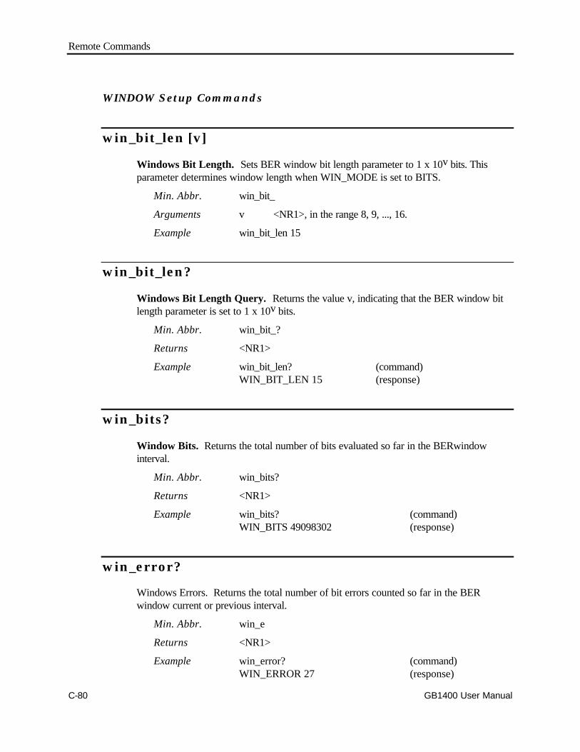
Remote Commands
C-80 GB1400 User Manual
WINDOW Setup Commands
win_bit_len [v]
Windows Bit Length. Sets BER window bit length parameter to 1 x 10v bits. Thisparameter determines window length when WIN_MODE is set to BITS.
Min. Abbr. win_bit_
Arguments v <NR1>, in the range 8, 9, ..., 16.
Example win_bit_len 15
win_bit_len?
Windows Bit Length Query. Returns the value v, indicating that the BER window bitlength parameter is set to 1 x 10v bits.
Min. Abbr. win_bit_?
Returns <NR1>
Example win_bit_len? (command)WIN_BIT_LEN 15 (response)
win_bits?
Window Bits. Returns the total number of bits evaluated so far in the BERwindowinterval.
Min. Abbr. win_bits?
Returns <NR1>
Example win_bits? (command)WIN_BITS 49098302 (response)
win_error?
Windows Errors. Returns the total number of bit errors counted so far in the BERwindow current or previous interval.
Min. Abbr. win_e
Returns <NR1>
Example win_error? (command)WIN_ERROR 27 (response)

Remote Commands
GB1400 User Manual C-81
win_mode [bits|sec]
Windows Mode. Determines whether BER window length is determined by thewindows bits (pattern length) parameter or the windows seconds (time length) parameter.
Min. Abbr. win_m
Arguments bits: selects the windows bits length parametersec: selects the windows seconds length parameter.
Example win_mode bits
win_mode?
Windows Mode Query. Returns the current BER window length mode.
Min. Abbr. win_m
Returns [bits|sec]
Example win_mode? (command)WIN_MODE BITS (response)
win_prev [current|previous]
Window Previous. Sets the WIN_PREV parameter to current or previous. Thisparameter determines whether Analyzer responses to win_bits?, win_error?, win_rate?,and win_time? queries will be based on the current window interval or the previouswindow interval.
Min. Abbr. win_p
Arguments current selects the current window intervalprevious selects the previous window interval
Example win_prev current
win_prev?
Window Previous Query. Returns the current value of the WIN_PREV parameter.
Min. Abbr. win_p
Returns [current|previous]
Example win_prev? (command)WIN_PREV CURRENT (response)
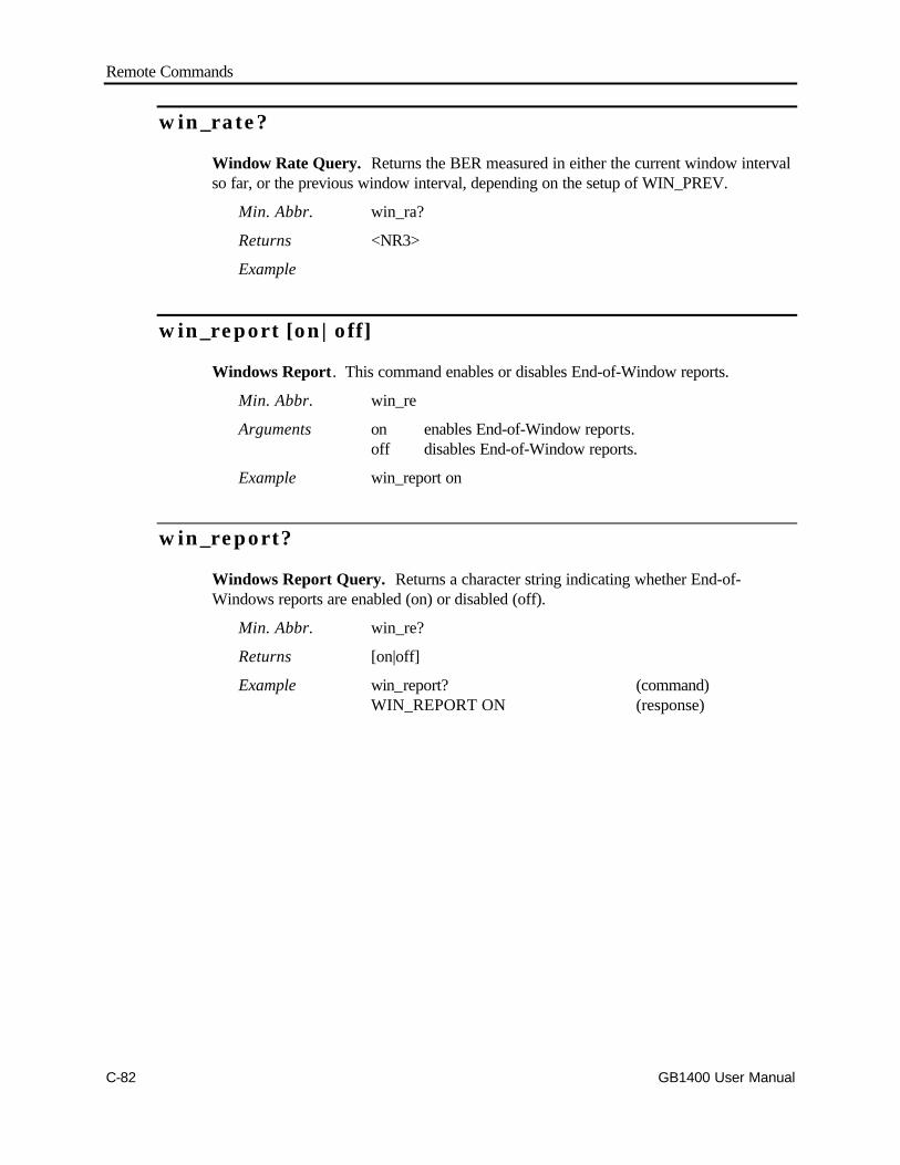
Remote Commands
C-82 GB1400 User Manual
win_rate?
Window Rate Query. Returns the BER measured in either the current window intervalso far, or the previous window interval, depending on the setup of WIN_PREV.
Min. Abbr. win_ra?
Returns <NR3>
Example
win_report [on|off]
Windows Report. This command enables or disables End-of-Window reports.
Min. Abbr. win_re
Arguments on enables End-of-Window reports.off disables End-of-Window reports.
Example win_report on
win_report?
Windows Report Query. Returns a character string indicating whether End-of-Windows reports are enabled (on) or disabled (off).
Min. Abbr. win_re?
Returns [on|off]
Example win_report? (command)WIN_REPORT ON (response)
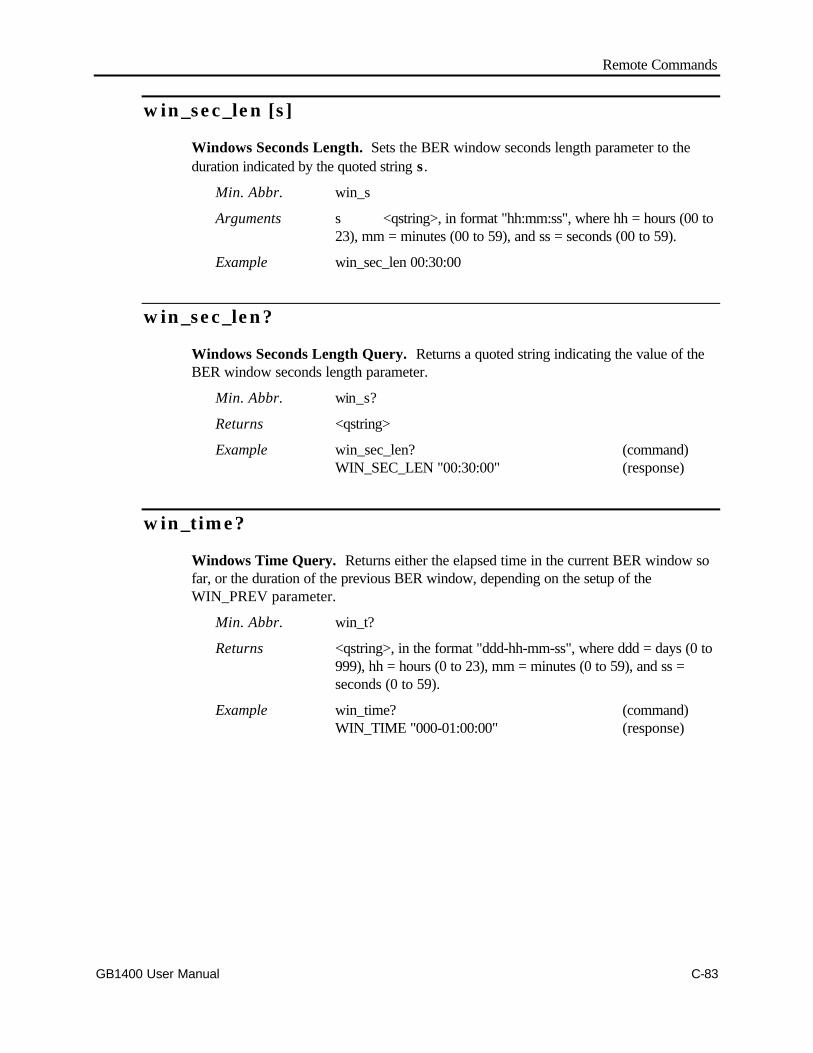
Remote Commands
GB1400 User Manual C-83
win_sec_len [s]
Windows Seconds Length. Sets the BER window seconds length parameter to theduration indicated by the quoted string s .
Min. Abbr. win_s
Arguments s <qstring>, in format "hh:mm:ss", where hh = hours (00 to23), mm = minutes (00 to 59), and ss = seconds (00 to 59).
Example win_sec_len 00:30:00
win_sec_len?
Windows Seconds Length Query. Returns a quoted string indicating the value of theBER window seconds length parameter.
Min. Abbr. win_s?
Returns <qstring>
Example win_sec_len? (command)WIN_SEC_LEN "00:30:00" (response)
win_time?
Windows Time Query. Returns either the elapsed time in the current BER window sofar, or the duration of the previous BER window, depending on the setup of theWIN_PREV parameter.
Min. Abbr. win_t?
Returns <qstring>, in the format "ddd-hh-mm-ss", where ddd = days (0 to999), hh = hours (0 to 23), mm = minutes (0 to 59), and ss =seconds (0 to 59).
Example win_time? (command)WIN_TIME "000-01:00:00" (response)
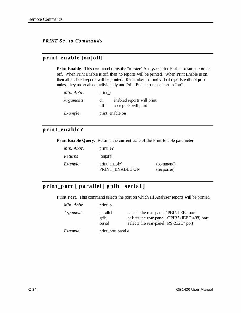
Remote Commands
C-84 GB1400 User Manual
PRINT Setup Commands
print_enable [on|| off]
Print Enable. This command turns the "master" Analyzer Print Enable parameter on oroff. When Print Enable is off, then no reports will be printed. When Print Enable is on,then all enabled reports will be printed. Remember that individual reports will not printunless they are enabled individually and Print Enable has been set to "on".
Min. Abbr. print_e
Arguments on enabled reports will print.off no reports will print
Example print_enable on
print_enable?
Print Enable Query. Returns the current state of the Print Enable parameter.
Min. Abbr. print_e?
Returns [on|off]
Example print_enable? (command)PRINT_ENABLE ON (response)
print_port [ parallel || gpib || serial ]
Print Port. This command selects the port on which all Analyzer reports will be printed.
Min. Abbr. print_p
Arguments parallel selects the rear-panel "PRINTER" portgpib selects the rear-panel "GPIB" (IEEE-488) port.serial selects the rear-panel "RS-232C" port.
Example print_port parallel
Remote Commands
GB1400 User Manual C-85
print_port?
Print Port Query. Returns the currently selected printer port.
Min. Abbr. print_p?
Returns [ parallel | gpib | serial ]
Example print_port? (command)PRINT_PORT PARALLEL (response)
print_string ["s"]
Print String. This command prints a character string s to the currently selected printerport.
Min. Abbr. print_s
Arguments "s" a character string enclosed in quotes.
Example print_string "This is a test"
Remote Commands
C-86 GB1400 User Manual
Audio Beeper Setup Commands
audio_rat_up andaudio_rat_dn
Audio Rate Up/Down (Default). This command pair is used to increment(audio_rat_up) or decrement (audio_rat_dn) by one the exponent of the current error ratethreshold of the BER beeper.
Min. Abbr. audio_rat_uaudio_rat_d
Arguments none
Example audio_rat_up
This command adds one to the exponent of the beeper BERthreshold.
audio_rat_up [v] andaudio_rat_dn [v]
Audio Rate Up/Down. This command pair is used to increment (audio_rat_up) ordecrement (audio_rat_dn) the exponent of the error beeper BER threshold by an amountv. Note that because the exponent is negative, the audio_rat_up command decreases theBER threshold while audio_rat_dn increases the threshold.
Min. Abbr. audio_rat_uaudio_rat_d
Arguments v: 1, 2, 3, ..., 14.
Example audio_rat_up 9
The above example adds 9 to the exponent, for example changingthe audio rate threshold from 1 x 10⁻³ to 1 x 10-12.
audio_rate [v]
Audio Rate. Sets the BER threshold for the error beeper to 1 x 10-v.
Min. Abbr. audio_rate
Arguments v: 2, 3, ..., 16
Example audio_rate 9

Remote Commands
GB1400 User Manual C-87
audio_rate?
Audio Rate Query. Returns the current error beeper BER threshold.
Returns <NR1>
Example audio_rate? (command)AUDIO_RATE 9 (response)
audio_vol [v]
Audio Volume. Sets the volume of the error beeper to v, where v can range from 0(off) to 4 (maximum volume).
Min. Abbr. audio_vol
Arguments v: 0, 1, 2, 3, or 4
Example audio_vol 4
audio_vol?
Audio Volume Query. Returns a decimal number in the range 0, 1, 2, 3, or 4, thatrepresents the current error beeper .
Min. Abbr. audio_vol?
Returns <NR1>
Example audio_vol? (command)AUDIO_VOL 4 (response)
Remote Commands
C-88 GB1400 User Manual
audio_vol_up andaudio_vol_dn
Audio Volume Up/Down (Default). This command pair is used to increment(audio_vol_up) or decrement (audio_vol_dn) the current error beeper volume by onelevel.
Min. Abbr. audio_vol_uaudio_vol_d
Argument none
Example audio_vol_upaudio_vol_dn
audio_vol_up [v] andaudio_vol_dn [v]
Audio Volume Up/Down. This command pair is used to increment (audio_vol_up) ordecrement (audio_vol_dn) the current error beeper volume by "v" levels.
Min. Abbr. audio_vol_uaudio_vol_d
Argument v <NR1>, 1, 2, 3, or 4
Example audio_vol_up 2audio_vol_dn 2
Remote Commands
GB1400 User Manual C-89
Misc. Analyzer Commands
date ["yyyy-mm-dd"]
Date. Sets the current date in year-month-day format. Note that the argument is aquoted character string.
Min. Abbr. date
Arguments yyyy year (NOTE: may be above 2000)mm month (1, 2, ..., 12)dd day (1, 2, ..., 31)
Example date "2001-03-21"
date?
Date Query. Returns a quoted string that indicates the current date setup of theAnalyzer in year-month-day format.
Min. Abbr. date?
Returns <qstring>
Example date? (command)DATE "2001-03-02" (response)
Remote Commands
C-90 GB1400 User Manual
time [s]
Time. Used to set the instrument's time of day clock.
Min. Abbr. ti
Arguments s <qstring>, in the format "hh:mm:ss". wherehh = hours (00 ... 23), mm = minutes (00 ... 59), andss = seconds (00 ... 59).
Examples time 16:30:02
time?
Time Query. Returns a quoted string indicating the current setting of the instrument'stime of day clock.
Min. Abbr. ti?
Returns <qstring>
Example time? (command)TIME "16:30:11.45" (response)
Remote Commands
GB1400 User Manual C-91
1 MB Option CommandsThe following section identifies commands that are modified or added when the 1 MBOption is installed.
Modified Commands
When the 1 MB Option is installed, the All_mem command will operate as before exceptthat it will not return any saved word patterns.
Replaced Commands
The standard GB1400 Generator and Analyzer command set includes the following"word" commands:
word_bits; word_memory ; word_length ; word_mem_len
These commands are limited to creating and editing short word patterns, that is patternsthat are 8 or 16 bits in length. They will not work on long word patterns. Instead, longword editing functions are performed using "byte" commands, which are added as part ofthe 1 MB Option. Moreover, byte commands also work on short words. Therefore,"word" commands have limited application in instruments equipped with the 1 MB Option.
However, "word" commands will still function in units equipped with the 1 MB Option.This insures that a Generator or Analyzer equipped with the 1 MB Option can replace astandard unit in automated applications designed to use standard (short word) commands.
Commands specific to I MB Option
When the 1 MB Option is installed all of the following commands are added to theGenerator and Analyzer command sets except for the byte_sync command, which isadded to only the Analyzer command set.
The following general rules apply to new 1 MB commands:
1. Commands used to edit long words execute properly only when received after anedit_begin command and before an edit_end command. These include:
q byte_lengthq byte_fillq byte_blockq byte_editq byte_insertq byte_delete
2. If a command includes a bit address argument [a], then [a] must be less than thelength, which can be specified by the byte_length command.
Remote Commands
C-92 GB1400 User Manual
byte_block [a], [i], [b1], ..., [bn]
Byte Block. This command overwrites a block of i bits in the edit pattern, beginning ataddress a, with the overwrite pattern indicated by bytes b1 through bn.
Min. Abbr. byte_b
Arguments a <NR1>, the following ranges indicate the startingaddress of the overwrite block.
0 to 131071 (1M mode)
0 to 65535 (512K mode)
0 to 32767 (256K mode)
0 to 16,383 (128K mode)
0 to 8191 (64K mode)
i <NR1>, in the range 1 to 80, the number of bits tooverwrite. 10 Bytes maximum.
b1, ..., bn <non-decimal numeric(s)> Indicating the bytes thatmake up the overwrite pattern. Each byte may be inthe range #H00 to #HFF (hex), #Q000 to #Q377(octal), or #B00000000 to #B11111111 (binary).
Example byte_block 4096, 24, #HBB, #H10, #HFF
Note: The address "a" plus the number of bytes being changed ('i'/8) must be less thanthe pattern length.
Note: n of "bn" must equal 1/8.

Remote Commands
GB1400 User Manual C-93
byte_block? [a]
Byte Block Query. Returns the hex., octal, or binary representation of the 80 bit sectionof the edit pattern beginning with the bit at address a. Note that if there is no editingsession in progress, this command will return the indicated 80 bit section from the currentword pattern.
"a" 0 to 131071 (1M mode)
0 to 65535 (512K mode)
0 to 32767 (256K mode)
0 to 16,383 (128K mode)
0 to 8191 (64K mode)
Min. Abbr. byte_b?
Response [a], [i], [b1], ..., [b2] in format: <NR1>, <NR1>, <non-dec. numeric(s)>
Example byte_block? 500BYTE_BLOCK 500, 16, #H12, #HF1
NOTE: If address [a] is within 10 bytes of the end of the pattern, then less than 10 byteswill be returned. Also, if the last byte of the pattern is included in the requested block, andthis byte contains one or more unused bits, then these bits will be returned with a value of0.
Remote Commands
C-94 GB1400 User Manual
byte_delete [a], [i]
Byte Delete. This command deletes i bits from the edit pattern starting with bit a.
Min. Abbr. byte_d
Arguments a <NR1>, in the range "a", the block of bits to be deletedbegins at this address.
0 to 131071 (1M mode)
0 to 65535 (512K mode)
0 to 32767 (256K mode)
0 to 16,383 (128K mode)
0 to 8191 (64K mode)
i <NR1>, in the range 8 to 80, in steps of 8, this is thenumber of bits to delete.
Example byte_delete 512, 80
Note: The address "a" plus the number of bytes being changed ('i'/8) must be less thanthe pattern length.
Note: n of "bn" must equal 1/8.

Remote Commands
GB1400 User Manual C-95
byte_edit [a], [b1]
Byte Edit. This command is similar to byte_block except that it can overwrite (edit) onlyone byte at a time. The command overwrites 8 bits starting at address a.
Min. Abbr. byte_e
Arguments a <NR1>, in the range "a", the address of the overwritebyte.
0 to 131071 (1M mode)
0 to 65535 (512K mode)
0 to 32767 (256K mode)
0 to 16,383 (128K mode)
0 to 8191 (64K mode)
b1 <non-decimal numeric> indicates the overwrite bytepattern. May be in the range #H00 to #HFF (hex),#Q000 to #Q377 (octal), or #B00000000 to#B11111111 (binary).
Example byte_edit 1000, #Q320
byte_edit? [a]
Byte Edit Query. Returns the hex., octal, or binary representation of the C-bit sectionof the edit pattern at address a.
Note that if there is no editing session in progress, this command will return the indicatedbyte from the current word pattern.
Min. Abbr. byte_e?
Response [a], [b1] in the format <NR1>, <non-decimal numeric>
Example byte_edit? (command)BYTE_EDIT 500, #H12 (response)
NOTE: If the returned byte is the last byte, and if this byte contains one or more unused bits,then these bits will be returned with a value of 0.
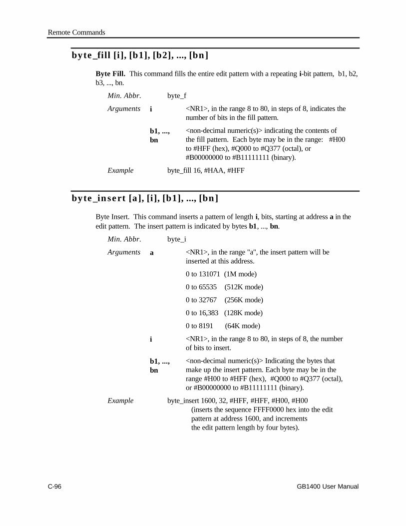
Remote Commands
C-96 GB1400 User Manual
byte_fill [i], [b1], [b2], ..., [bn]
Byte Fill. This command fills the entire edit pattern with a repeating i-bit pattern, b1, b2,b3, ..., bn.
Min. Abbr. byte_f
Arguments i <NR1>, in the range 8 to 80, in steps of 8, indicates thenumber of bits in the fill pattern.
b1, ...,bn
<non-decimal numeric(s)> indicating the contents ofthe fill pattern. Each byte may be in the range: #H00to #HFF (hex), #Q000 to #Q377 (octal), or#B00000000 to #B11111111 (binary).
Example byte_fill 16, #HAA, #HFF
byte_insert [a], [i], [b1], ..., [bn]
Byte Insert. This command inserts a pattern of length i, bits, starting at address a in theedit pattern. The insert pattern is indicated by bytes b1, ..., bn.
Min. Abbr. byte_i
Arguments a <NR1>, in the range "a", the insert pattern will beinserted at this address.
0 to 131071 (1M mode)
0 to 65535 (512K mode)
0 to 32767 (256K mode)
0 to 16,383 (128K mode)
0 to 8191 (64K mode)
i <NR1>, in the range 8 to 80, in steps of 8, the numberof bits to insert.
b1, ...,bn
<non-decimal numeric(s)> Indicating the bytes thatmake up the insert pattern. Each byte may be in therange #H00 to #HFF (hex), #Q000 to #Q377 (octal),or #B00000000 to #B11111111 (binary).
Example byte_insert 1600, 32, #HFF, #HFF, #H00, #H00(inserts the sequence FFFF0000 hex into the editpattern at address 1600, and incrementsthe edit pattern length by four bytes).
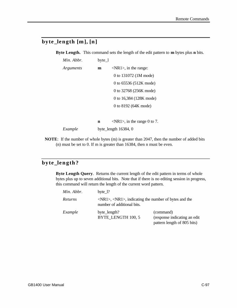
Remote Commands
GB1400 User Manual C-97
byte_length [m], [n]
Byte Length. This command sets the length of the edit pattern to m bytes plus n bits.
Min. Abbr. byte_l
Arguments m <NR1>, in the range:
0 to 131072 (1M mode)
0 to 65536 (512K mode)
0 to 32768 (256K mode)
0 to 16,384 (128K mode)
0 to 8192 (64K mode)
n <NR1>, in the range 0 to 7.
Example byte_length 16384, 0
NOTE: If the number of whole bytes (m) is greater than 2047, then the number of added bits(n) must be set to 0. If m is greater than 16384, then n must be even.
byte_length?
Byte Length Query. Returns the current length of the edit pattern in terms of wholebytes plus up to seven additional bits. Note that if there is no editing session in progress,this command will return the length of the current word pattern.
Min. Abbr. byte_l?
Returns <NR1>, <NR1>, indicating the number of bytes and thenumber of additional bits.
Example byte_length? (command)BYTE_LENGTH 100, 5 (response indicating an edit
pattern length of 805 bits)
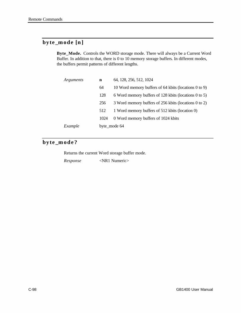
Remote Commands
C-98 GB1400 User Manual
byte_mode [n]
Byte_Mode. Controls the WORD storage mode. There will always be a Current WordBuffer. In addition to that, there is 0 to 10 memory storage buffers. In different modes,the buffers permit patterns of different lengths.
Arguments n 64, 128, 256, 512, 1024
64 10 Word memory buffers of 64 kbits (locations 0 to 9)
128 6 Word memory buffers of 128 kbits (locations 0 to 5)
256 3 Word memory buffers of 256 kbits (locations 0 to 2)
512 1 Word memory buffers of 512 kbits (location 0)
1024 0 Word memory buffers of 1024 kbits
Example byte_mode 64
byte_mode?
Returns the current Word storage buffer mode.
Response <NR1 Numeric>

Remote Commands
GB1400 User Manual C-99
byte_sync [n] (Analyzer only)
Byte Synchronization. This command sets the long-word pattern synchronizationthreshold. This threshold does not apply to short-word patterns, or PRBS patterns. Thelong-word synchronization threshold is set in terms of an integer, n, which corresponds toa BER threshold. In the table below, the ratios of errors to bits corrrespond to the windowexamined and the maximum errors for the threshold.
Level BER Ratio (errors/bits)
1 3.1E-2 (256/8192)
2 7.8E-3 (256/32768)
3 1.9E-3 (256/131072)
4 9.7E-4 (256/262144)
5 4.8E-4 (256/524288)
6 2.4E-4 (256/1048576)
7 1.2E-4 (256/2097152)
8 6.1E-5 (256/4194304)
9 3.0E-5 (256/8388608)
Min. Abbr. byte_s
Arguments i <NR1>, in the range 1 (highest BER) to 9 (lowest BER).
Example byte_sync 4
NOTE: This command is found in the Analyzer command set only.
byte_sync? (Analyzer only)
Byte Synchronization Query. Returns a single decimal digit which represents thecurrent long-word synchronization threshold.
Min. Abbr. byte_s?
Returns <NR1>
Example byte_sync?BYTE_SYNC 4

Remote Commands
C-100 GB1400 User Manual
edit_begin [n]
Edit Begin. You must issue this command to the instrument before starting an editingsession. In effect this command loads the contents of a word memory location specifiedby n into a scratch pad memory location. Once in the scratch pad memory it can beedited, uploaded to the controller, or saved to the same or a different memory location.You also must issue the edit_begin command before downloading a word pattern to theinstrument.
Min. Abbr. edit_b
Arguments n <NR1>, a decimal number in the range -1 to 9, where -1indicates the current word pattern and 0 through 9 indicate thememory locations.
-1 only (1M and 512K modes)
-1 to 2 (256K mode)
-1 to 5 (128K mode)
-1 to 9 (64K mode)
Example edit_begin 2

Remote Commands
GB1400 User Manual C-101
edit_cntrl?
Edit Control Query. This command returns a character string that indicates whether ornot a long-word (1 MB Option) editing session is in progress and if that session is underlocal or remote control.
Min. Abbr. edit_c
Returns [local|remote|none], where:
local: indicates a long-word editing session is inprogress under local (front panel) control
remote: indicates a long-word editing session is inprogress under remote (RS-232C or GPIB)control
none: indicates that there is no long-word editingsession in progress
Example edit_cntrl? (command)EDIT_CNTRL NONE (response)
edit_end [n]
Edit End. You must issue this command to finish a 1 MB word editing session. Thiscommand either moves the edited pattern from scratchpad memory to the current wordlocation, or saves the edited pattern into one of the instruments eight word memorylocations. You can also use this command to discard the edit pattern.
Min. Abbr. edit_e
Arguments n <NR1>, a decimal number in the range -2 to 9, where -2 discardsthe edited pattern, -1 copies the edited pattern to the currentword location, and 0 through 9 saves the edited pattern to theindicated memory location.
-1 only (1M and 512K modes)
-2 to 2 (256K mode)
-2 to 5 (128K mode)
-2 to 9 (64K mode)
Example edit_end -1

Remote Commands
C-102 GB1400 User Manual
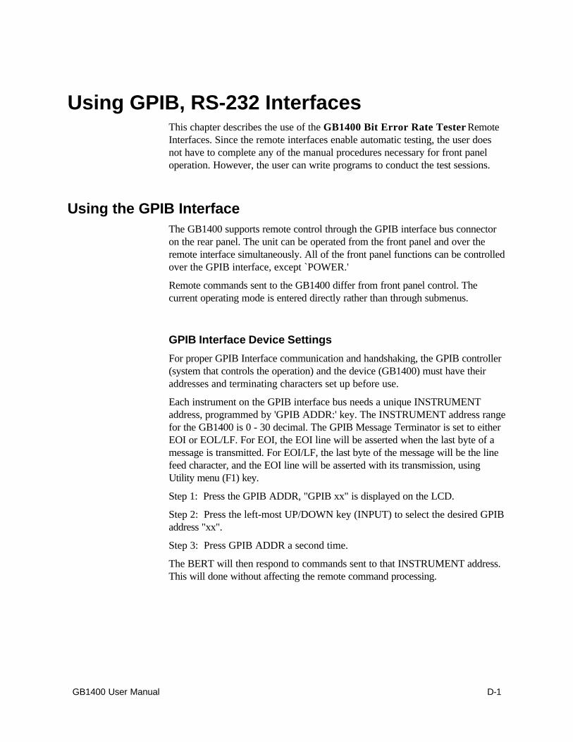
GB1400 User Manual D-1
Using GPIB, RS-232 InterfacesThis chapter describes the use of the GB1400 Bit Error Rate Tester RemoteInterfaces. Since the remote interfaces enable automatic testing, the user doesnot have to complete any of the manual procedures necessary for front paneloperation. However, the user can write programs to conduct the test sessions.
Using the GPIB InterfaceThe GB1400 supports remote control through the GPIB interface bus connectoron the rear panel. The unit can be operated from the front panel and over theremote interface simultaneously. All of the front panel functions can be controlledover the GPIB interface, except `POWER.'
Remote commands sent to the GB1400 differ from front panel control. Thecurrent operating mode is entered directly rather than through submenus.
GPIB Interface Device Settings
For proper GPIB Interface communication and handshaking, the GPIB controller(system that controls the operation) and the device (GB1400) must have theiraddresses and terminating characters set up before use.
Each instrument on the GPIB interface bus needs a unique INSTRUMENTaddress, programmed by 'GPIB ADDR:' key. The INSTRUMENT address rangefor the GB1400 is 0 - 30 decimal. The GPIB Message Terminator is set to eitherEOI or EOL/LF. For EOI, the EOI line will be asserted when the last byte of amessage is transmitted. For EOI/LF, the last byte of the message will be the linefeed character, and the EOI line will be asserted with its transmission, usingUtility menu (F1) key.
Step 1: Press the GPIB ADDR, "GPIB xx" is displayed on the LCD.
Step 2: Press the left-most UP/DOWN key (INPUT) to select the desired GPIBaddress "xx".
Step 3: Press GPIB ADDR a second time.
The BERT will then respond to commands sent to that INSTRUMENT address.This will done without affecting the remote command processing.
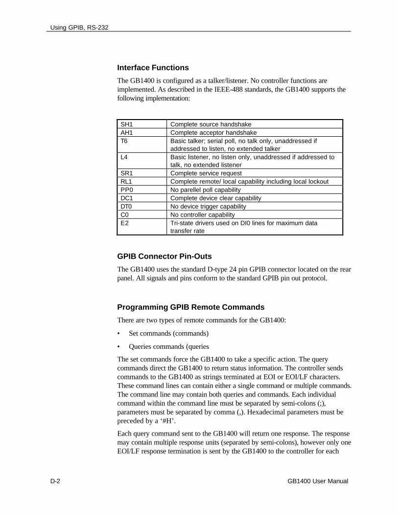
Using GPIB, RS-232
D-2 GB1400 User Manual
Interface Functions
The GB1400 is configured as a talker/listener. No controller functions areimplemented. As described in the IEEE-488 standards, the GB1400 supports thefollowing implementation:
SH1 Complete source handshakeAH1 Complete acceptor handshakeT6 Basic talker; serial poll, no talk only, unaddressed if
addressed to listen, no extended talkerL4 Basic listener, no listen only, unaddressed if addressed to
talk, no extended listenerSR1 Complete service requestRL1 Complete remote/ local capability including local lockoutPP0 No parellel poll capabilityDC1 Complete device clear capabilityDT0 No device trigger capabilityC0 No controller capabilityE2 Tri-state drivers used on DI0 lines for maximum data
transfer rate
GPIB Connector Pin-Outs
The GB1400 uses the standard D-type 24 pin GPIB connector located on the rearpanel. All signals and pins conform to the standard GPIB pin out protocol.
Programming GPIB Remote Commands
There are two types of remote commands for the GB1400:
• Set commands (commands)
• Queries commands (queries
The set commands force the GB1400 to take a specific action. The querycommands direct the GB1400 to return status information. The controller sendscommands to the GB1400 as strings terminated at EOI or EOI/LF characters.These command lines can contain either a single command or multiple commands.The command line may contain both queries and commands. Each individualcommand within the command line must be separated by semi-colons (;),parameters must be separated by comma (,). Hexadecimal parameters must bepreceded by a ‘#H’.
Each query command sent to the GB1400 will return one response. The responsemay contain multiple response units (separated by semi-colons), however only oneEOI/LF response termination is sent by the GB1400 to the controller for each
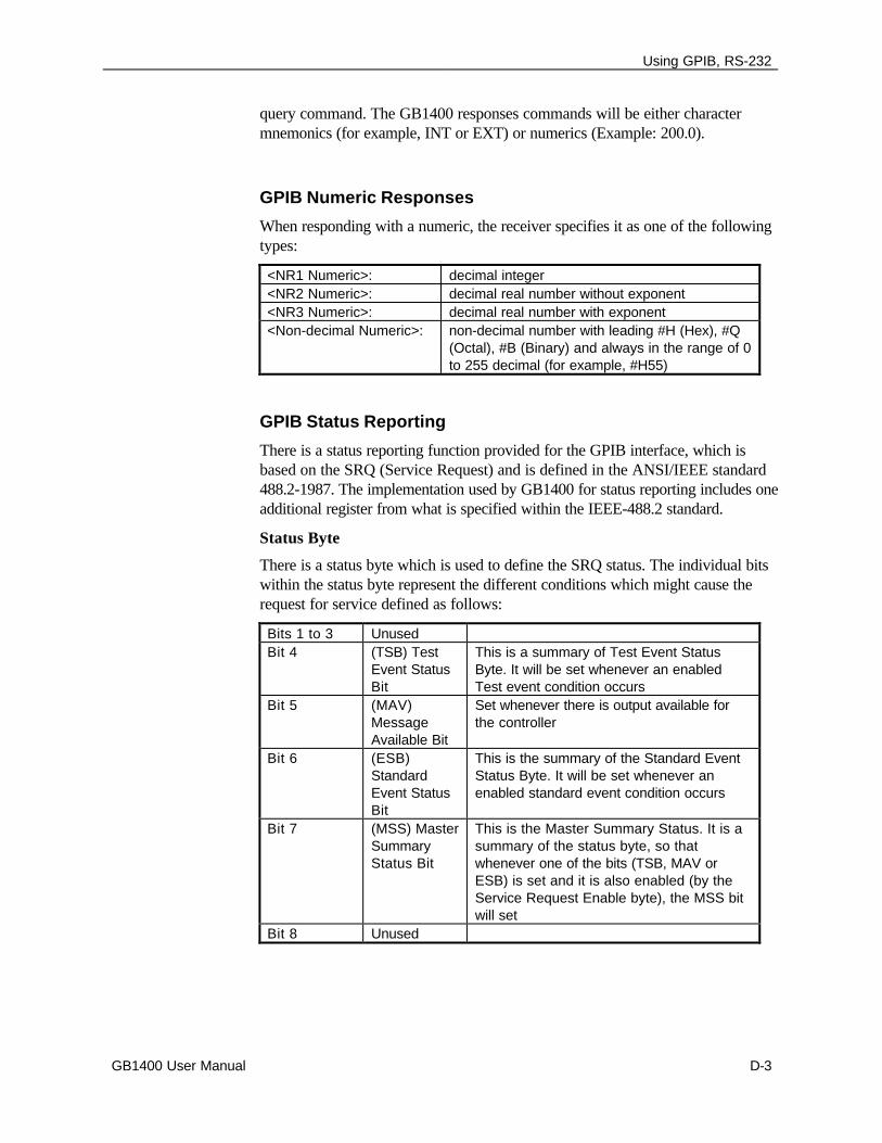
Using GPIB, RS-232
GB1400 User Manual D-3
query command. The GB1400 responses commands will be either charactermnemonics (for example, INT or EXT) or numerics (Example: 200.0).
GPIB Numeric Responses
When responding with a numeric, the receiver specifies it as one of the followingtypes:
<NR1 Numeric>: decimal integer<NR2 Numeric>: decimal real number without exponent<NR3 Numeric>: decimal real number with exponent<Non-decimal Numeric>: non-decimal number with leading #H (Hex), #Q
(Octal), #B (Binary) and always in the range of 0to 255 decimal (for example, #H55)
GPIB Status Reporting
There is a status reporting function provided for the GPIB interface, which isbased on the SRQ (Service Request) and is defined in the ANSI/IEEE standard488.2-1987. The implementation used by GB1400 for status reporting includes oneadditional register from what is specified within the IEEE-488.2 standard.
Status Byte
There is a status byte which is used to define the SRQ status. The individual bitswithin the status byte represent the different conditions which might cause therequest for service defined as follows:
Bits 1 to 3 UnusedBit 4 (TSB) Test
Event StatusBit
This is a summary of Test Event StatusByte. It will be set whenever an enabledTest event condition occurs
Bit 5 (MAV)MessageAvailable Bit
Set whenever there is output available forthe controller
Bit 6 (ESB)StandardEvent StatusBit
This is the summary of the Standard EventStatus Byte. It will be set whenever anenabled standard event condition occurs
Bit 7 (MSS) MasterSummaryStatus Bit
This is the Master Summary Status. It is asummary of the status byte, so thatwhenever one of the bits (TSB, MAV orESB) is set and it is also enabled (by theService Request Enable byte), the MSS bitwill set
Bit 8 Unused

Using GPIB, RS-232
D-4 GB1400 User Manual
Service Request Enable
Different conditions for a service request can be individually enabled. The ServiceRequest Enable byte contains the enabling bits for the status byte. For a servicerequest to occur, either the TSB, MAV or ESB bit must be enabled. Each timethe GB1400 is powered on, this byte is RESET so that no bits are enabled. The bitdefinition is the same as the status byte, except bit 7 is undefined.
Service Request (SRQ)
The status byte enables the creation of a service request. Whenever a conditionrequiring service from the controller occurs and is enabled, the SRQ line is set. Itis reset after the controller finishes a serial poll of the GB1400 receiver, or whenall of the enabled service request conditions have stopped.
Standard Event Status Register
The ESB bit is the summary of the Standard Event Status Register. This byte hasan enabling byte similar to the Status Byte. Individual bits within the StandardEvent Status Register represent the different possible causes of a StandardEvent. The bit definitions for the Standard Event Status Register are as follows:
Bit 1 OperationComplete
Only set following an *OPC command
Bit 2 Request Control Not UsedBit 3 Query Error Set under the following conditions:
• when output has been requested from theGB1400 and none is available
• when a command is sent to the GB1400 andGB1400 still has a message available
• when output has been requested from theGB1400 and an unterminated command hasbeen set to the GB1400
Bit 4 DeviceDependent Error
Set under the following conditions:• when input data is lost over the interface• when the input buffer overflows due to a too-long
command line without a terminatorBit 5 Execution Error Set under the following conditions:
when a command parameter is out of rangewhen the command has too many or too fewparameterswhen the command cannot be properly executeddue to a device condition
Bit 6 Command Error Set whenever the GB1400 receives an unrecognizedcommand, or invalid GPIB command
Bit 7 User Request Not usedBit 8 Power On Set whenever the GB1400 is powered on
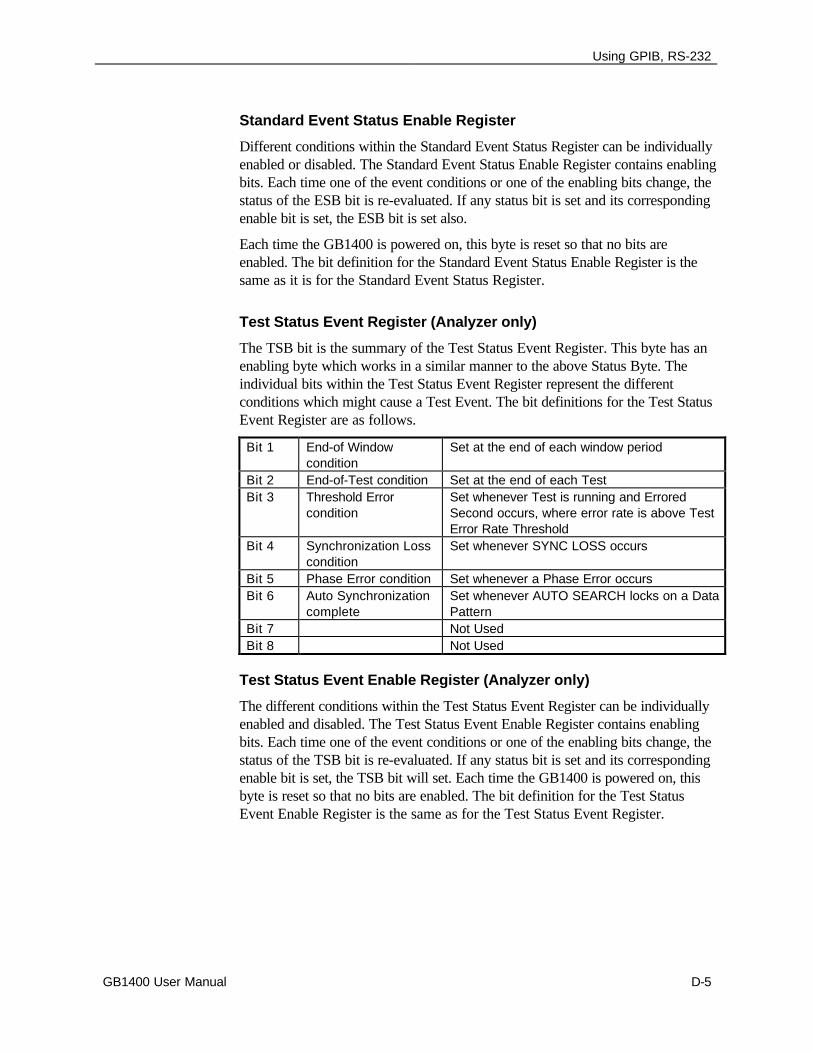
Using GPIB, RS-232
GB1400 User Manual D-5
Standard Event Status Enable Register
Different conditions within the Standard Event Status Register can be individuallyenabled or disabled. The Standard Event Status Enable Register contains enablingbits. Each time one of the event conditions or one of the enabling bits change, thestatus of the ESB bit is re-evaluated. If any status bit is set and its correspondingenable bit is set, the ESB bit is set also.
Each time the GB1400 is powered on, this byte is reset so that no bits areenabled. The bit definition for the Standard Event Status Enable Register is thesame as it is for the Standard Event Status Register.
Test Status Event Register (Analyzer only)
The TSB bit is the summary of the Test Status Event Register. This byte has anenabling byte which works in a similar manner to the above Status Byte. Theindividual bits within the Test Status Event Register represent the differentconditions which might cause a Test Event. The bit definitions for the Test StatusEvent Register are as follows.
Bit 1 End-of Windowcondition
Set at the end of each window period
Bit 2 End-of-Test condition Set at the end of each TestBit 3 Threshold Error
conditionSet whenever Test is running and ErroredSecond occurs, where error rate is above TestError Rate Threshold
Bit 4 Synchronization Losscondition
Set whenever SYNC LOSS occurs
Bit 5 Phase Error condition Set whenever a Phase Error occursBit 6 Auto Synchronization
completeSet whenever AUTO SEARCH locks on a DataPattern
Bit 7 Not UsedBit 8 Not Used
Test Status Event Enable Register (Analyzer only)
The different conditions within the Test Status Event Register can be individuallyenabled and disabled. The Test Status Event Enable Register contains enablingbits. Each time one of the event conditions or one of the enabling bits change, thestatus of the TSB bit is re-evaluated. If any status bit is set and its correspondingenable bit is set, the TSB bit will set. Each time the GB1400 is powered on, thisbyte is reset so that no bits are enabled. The bit definition for the Test StatusEvent Enable Register is the same as for the Test Status Event Register.

Using GPIB, RS-232
D-6 GB1400 User Manual
GPIB Common Commands
The following commands are provided to use with GPIB status reporting, asdefined by IEEE 488.2 for service request:
*STB? *SRE *SRE? *ESR? *ESE *ESE? *CLS
Additional SRQ GPIB Commands (Rx only)
The following commands are provided to use with the Test Status SRQ feature:
TSE TSE? TSR?
IEEE-488.2 Programming Manual Requirements
Certain programming requirements are specified for GPIB interfaces by theAmerican National Standard Institute (ANSI) document, ANSI/IEEE Std. 488.2-1987, which are detailed in this section.
Power-on settings
The GB1400 will restore the device settings to their same values from when itwas last powered off. No remote commands affect this. The only exception tothis is when the non-volatile RAM becomes corrupted (which should neverhappen during normal operation). RAM corruption, if it occurs, will be displayedon the unit’s LCD display. When this happens, the GB1400 will revert to itsfactory-default settings.
Message Exchange
The message exchange options are as follows:
• The input buffer is command line oriented. There is a new input buffer foreach command line or program message. The maximum input buffer length is80 characters.
• The only remote commands that return more than one response message unitare: *lrn?; sta?; rdm?; rfm?; all?
• All queries immediately generate their own response messages when parsed.No queries wait until the responses are read for them to be generated.
• No commands are coupled.
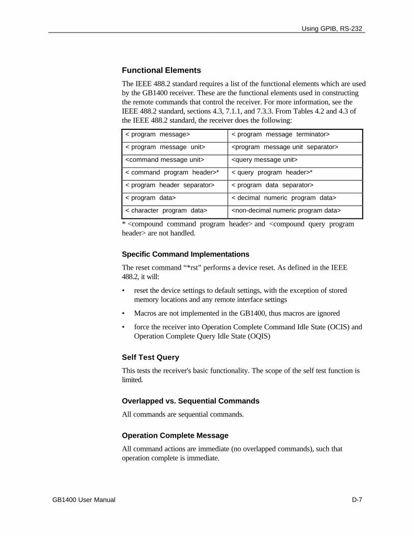
Using GPIB, RS-232
GB1400 User Manual D-7
Functional Elements
The IEEE 488.2 standard requires a list of the functional elements which are usedby the GB1400 receiver. These are the functional elements used in constructingthe remote commands that control the receiver. For more information, see theIEEE 488.2 standard, sections 4.3, 7.1.1, and 7.3.3. From Tables 4.2 and 4.3 ofthe IEEE 488.2 standard, the receiver does the following:
< program message> < program message terminator>
< program message unit> <program message unit separator>
<command message unit> <query message unit>
< command program header>* < query program header>*
< program header separator> < program data separator>
< program data> < decimal numeric program data>
< character program data> <non-decimal numeric program data>
* <compound command program header> and <compound query programheader> are not handled.
Specific Command Implementations
The reset command “*rst” performs a device reset. As defined in the IEEE488.2, it will:
• reset the device settings to default settings, with the exception of storedmemory locations and any remote interface settings
• Macros are not implemented in the GB1400, thus macros are ignored
• force the receiver into Operation Complete Command Idle State (OCIS) andOperation Complete Query Idle State (OQIS)
Self Test Query
This tests the receiver's basic functionality. The scope of the self test function islimited.
Overlapped vs. Sequential Commands
All commands are sequential commands.
Operation Complete Message
All command actions are immediate (no overlapped commands), such thatoperation complete is immediate.
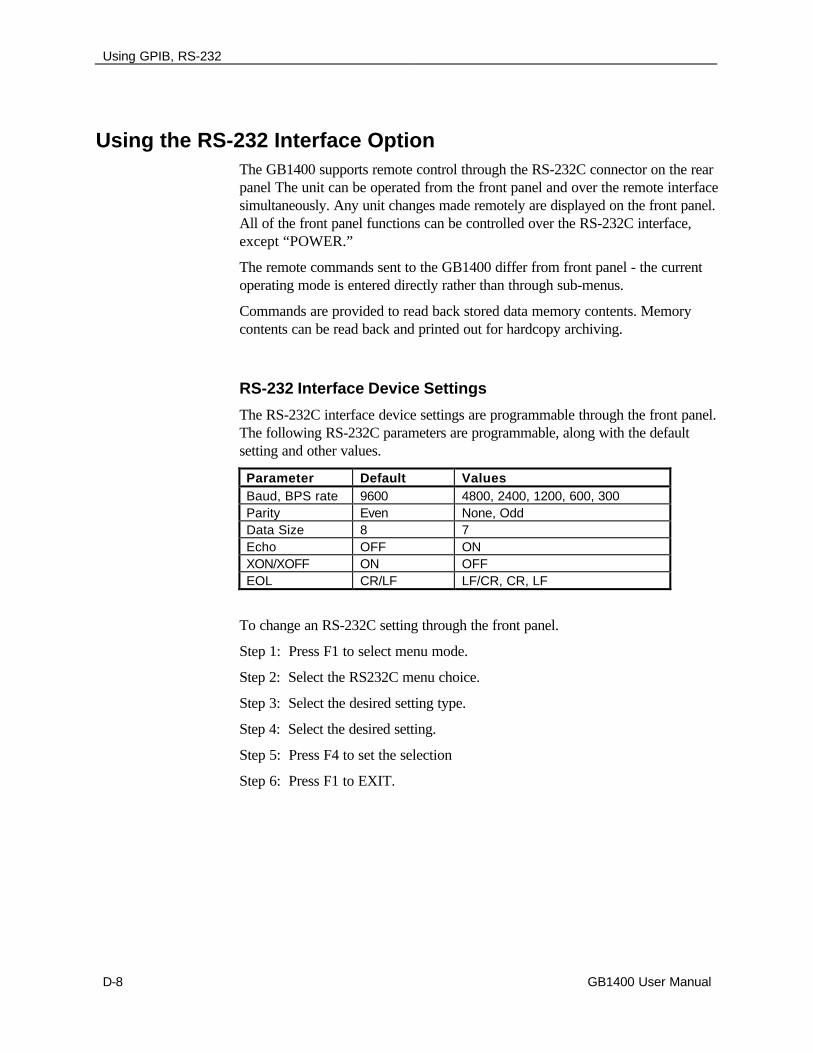
Using GPIB, RS-232
D-8 GB1400 User Manual
Using the RS-232 Interface OptionThe GB1400 supports remote control through the RS-232C connector on the rearpanel The unit can be operated from the front panel and over the remote interfacesimultaneously. Any unit changes made remotely are displayed on the front panel.All of the front panel functions can be controlled over the RS-232C interface,except “POWER.”
The remote commands sent to the GB1400 differ from front panel - the currentoperating mode is entered directly rather than through sub-menus.
Commands are provided to read back stored data memory contents. Memorycontents can be read back and printed out for hardcopy archiving.
RS-232 Interface Device Settings
The RS-232C interface device settings are programmable through the front panel.The following RS-232C parameters are programmable, along with the defaultsetting and other values.
Parameter Default ValuesBaud, BPS rate 9600 4800, 2400, 1200, 600, 300Parity Even None, OddData Size 8 7Echo OFF ONXON/XOFF ON OFFEOL CR/LF LF/CR, CR, LF
To change an RS-232C setting through the front panel.
Step 1: Press F1 to select menu mode.
Step 2: Select the RS232C menu choice.
Step 3: Select the desired setting type.
Step 4: Select the desired setting.
Step 5: Press F4 to set the selection
Step 6: Press F1 to EXIT.
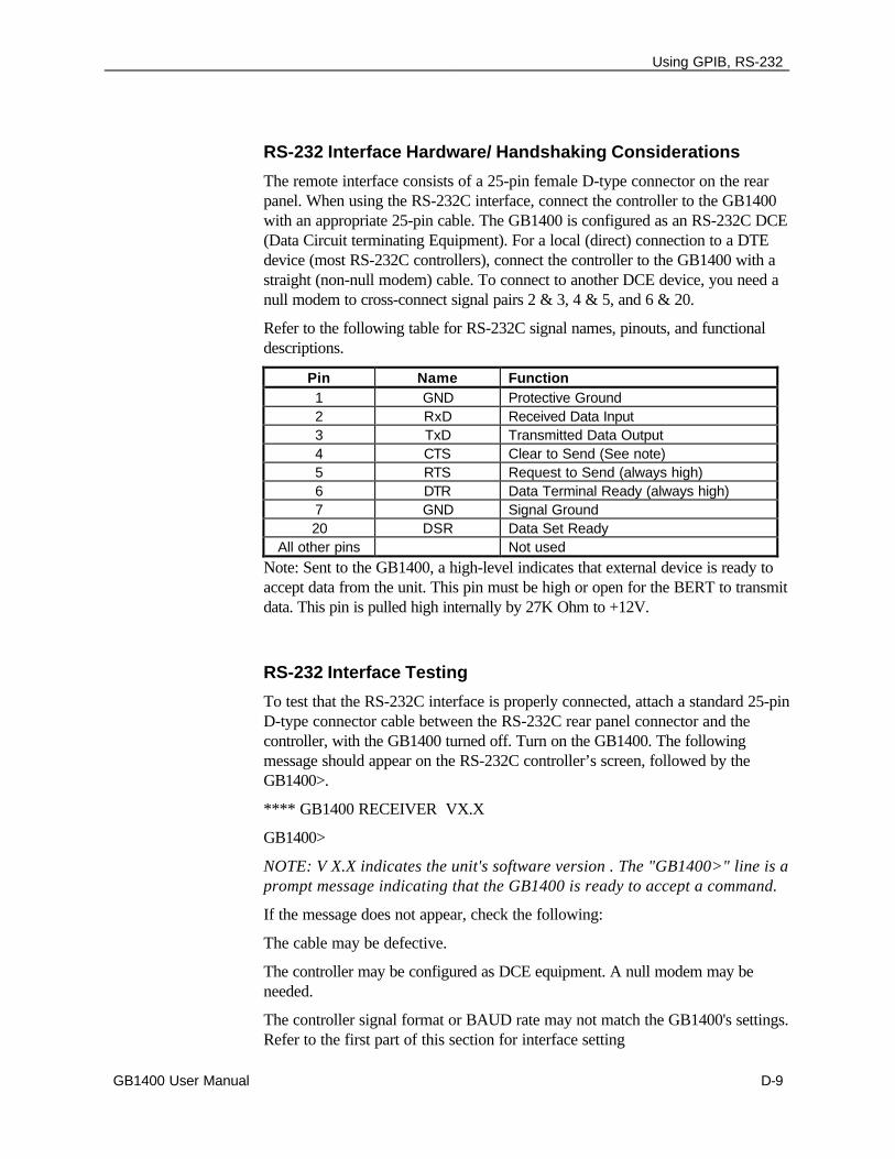
Using GPIB, RS-232
GB1400 User Manual D-9
RS-232 Interface Hardware/ Handshaking Considerations
The remote interface consists of a 25-pin female D-type connector on the rearpanel. When using the RS-232C interface, connect the controller to the GB1400with an appropriate 25-pin cable. The GB1400 is configured as an RS-232C DCE(Data Circuit terminating Equipment). For a local (direct) connection to a DTEdevice (most RS-232C controllers), connect the controller to the GB1400 with astraight (non-null modem) cable. To connect to another DCE device, you need anull modem to cross-connect signal pairs 2 & 3, 4 & 5, and 6 & 20.
Refer to the following table for RS-232C signal names, pinouts, and functionaldescriptions.
Pin Name Function1 GND Protective Ground2 RxD Received Data Input3 TxD Transmitted Data Output4 CTS Clear to Send (See note)5 RTS Request to Send (always high)6 DTR Data Terminal Ready (always high)7 GND Signal Ground20 DSR Data Set Ready
All other pins Not usedNote: Sent to the GB1400, a high-level indicates that external device is ready toaccept data from the unit. This pin must be high or open for the BERT to transmitdata. This pin is pulled high internally by 27K Ohm to +12V.
RS-232 Interface Testing
To test that the RS-232C interface is properly connected, attach a standard 25-pinD-type connector cable between the RS-232C rear panel connector and thecontroller, with the GB1400 turned off. Turn on the GB1400. The followingmessage should appear on the RS-232C controller’s screen, followed by theGB1400>.
**** GB1400 RECEIVER VX.X
GB1400>
NOTE: V X.X indicates the unit's software version . The "GB1400>" line is aprompt message indicating that the GB1400 is ready to accept a command.
If the message does not appear, check the following:
The cable may be defective.
The controller may be configured as DCE equipment. A null modem may beneeded.
The controller signal format or BAUD rate may not match the GB1400's settings.Refer to the first part of this section for interface setting

Using GPIB, RS-232
D-10 GB1400 User Manual
Programming RS-232C Remote Commands
There are two types of remote commands for the GB1400:
• Set commands (commands)
• Queries commands (queries
The set commands force the GB1400 to take a specific action. The querycommands direct the GB1400 to return status information.
Commands are entered one line at a time. Errors may be corrected while enteringa line, with the backspace key. A command string is terminated by a carriagereturn, which transmits the string to the GB1400 and executes the commandstring. All valid commands are executed. Incorrect or unsupported commands areresponded to by an error message. RS-232C error messages follow after thissection.
These command lines can contain either a single command or multiple commands.The command line may contain both queries and commands. Each individualcommand within the command line must be separated by semi-colons (;),parameters must be separated by comma (,). Non-decimal numeric parameters,Hexadecimal, Octal, and Binary must be preceded by a ‘#H’, ‘#Q’, or ‘#B’,respectively. The entire command name does not have to be completely enteredfor the command to be recognized as valid. There is a minimum valid lengthassociated with each command, which is the length that makes it unique from allother commands.
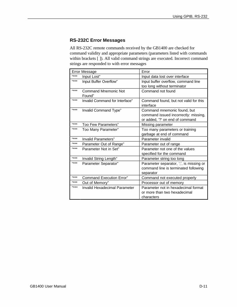
Using GPIB, RS-232
GB1400 User Manual D-11
RS-232C Error Messages
All RS-232C remote commands received by the GB1400 are checked forcommand validity and appropriate parameters (parameters listed with commandswithin brackets [ ]). All valid command strings are executed. Incorrect commandstrings are responded to with error messages
Error Message Error“*** Input Lost” Input data lost over interface“*** Input Buffer Overflow” Input buffer overflow, command line
too long without terminator“*** Command Mnemonic Not
Found”Command not found
“*** Invalid Command for Interface” Command found, but not valid for thisinterface
“*** Invalid Command Type” Command mnemonic found, butcommand issued incorrectly: missing,or added, '?' on end of command
“*** Too Few Parameters” Missing parameter“*** Too Many Parameter” Too many parameters or training
garbage at end of command“*** Invalid Parameters” Parameter invalid“*** Parameter Out of Range” Parameter out of range“*** Parameter Not in Set” Parameter not one of the values
specified for the command“*** Invalid String Length” Parameter string too long“*** Parameter Separator” Parameter separator, ‘;’, is missing or
command line is terminated followingseparator
“*** Command Execution Error” Command not executed properly“*** Out of Memory” Processor out of memory"*** Invalid Hexadecimal Parameter Parameter not in hexadecimal format
or more than two hexadecimalcharacters

Using GPIB, RS-232
D-12 GB1400 User Manual
GB1400 Acceptance Test E-1
p
Customer Acceptance TestFor
GB1400 Generator & Analyzer
NOTICE TO ALL PERSONS RECEIVING THIS DOCUMENT
THIS DOCUMENT IS ONLY CONDITIONALLY ISSUED, AND NEITHER RECEIPT NOR POSSESSIONTHEREOF CONFERS OR TRANSFERS ANY RIGHT IN, OR LICENSE TO USE, THE SUBJECT MATTEROF THE DOCUMENT OR ANY DESIGN OR TECHNICAL INFORMATION SHOWN THEREON, NOR ANYRIGHT TO REPRODUCE THIS DOCUMENT OR ANY PART THEREOF, EXCEPT FOR MANUFACTURE BYVENDORS FOR TEKTRONIX AND FOR MANUFACTURE UNDER THE CORPORATION’S WRITTENLICENSE, NO RIGHT TO REPRODUCE THE DOCUMENT IS GRANTED UNLESS BY WRITTENAGREEMENT WITH OR WRITTEN PERMISSION FROM THE CORPORATION.
Revision History
Date Description Pages Affected
9/29/94 Initial Release Whole Document
9/3/96 Change Name to Tektronx Whole Document
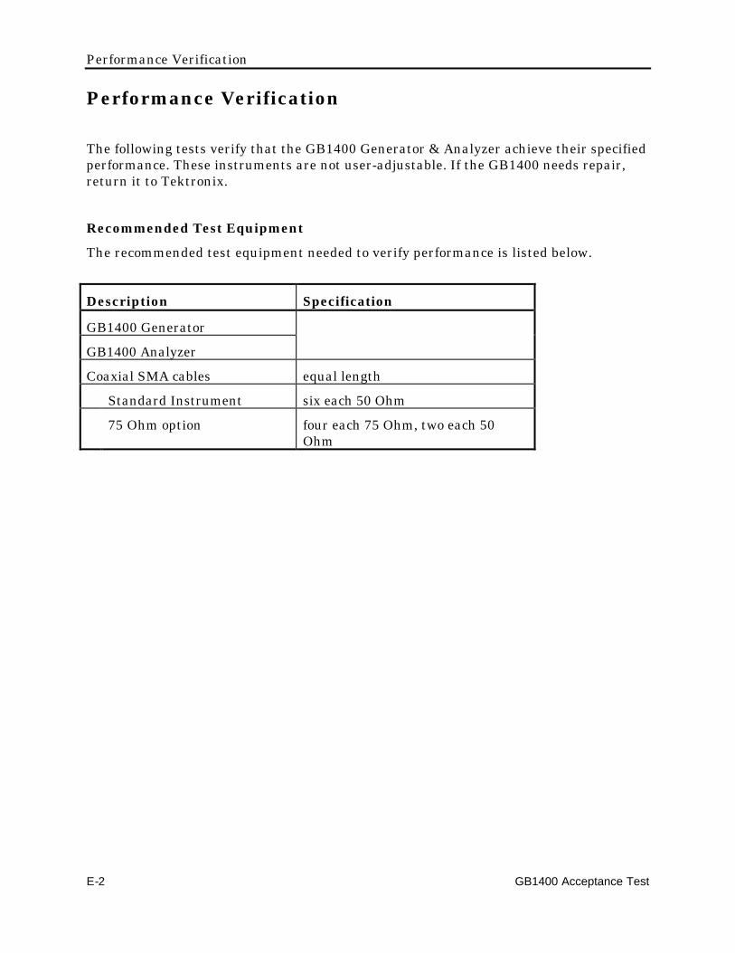
Performance Verification
E-2 GB1400 Acceptance Test
Performance Verification
The following tests verify that the GB1400 Generator & Analyzer achieve their specifiedperformance. These instruments are not user-adjustable. If the GB1400 needs repair,return it to Tektronix.
Recommended Test Equipment
The recommended test equipment needed to verify performance is listed below.
Description Specification
GB1400 Generator
GB1400 Analyzer
Coaxial SMA cables equal length
Standard Instrument six each 50 Ohm
75 Ohm option four each 75 Ohm, two each 50Ohm
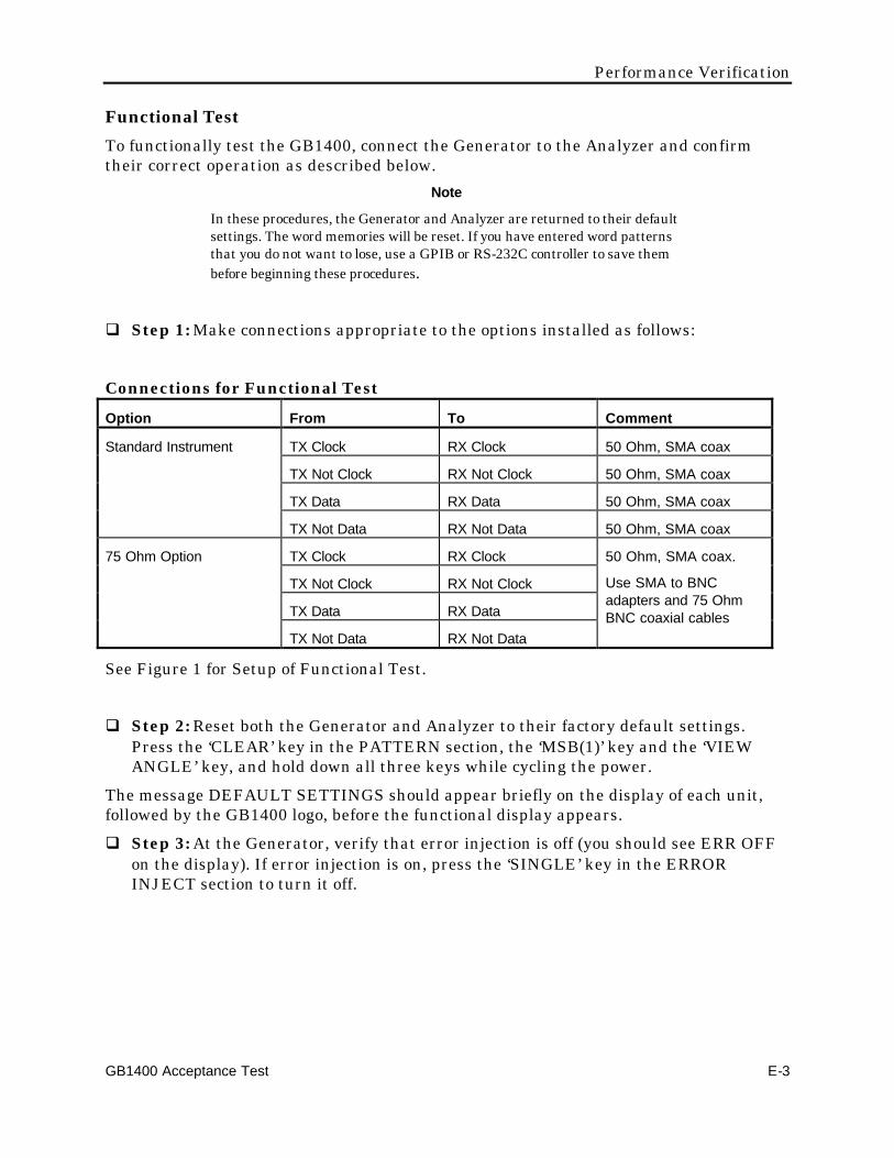
Performance Verification
GB1400 Acceptance Test E-3
Functional TestTo functionally test the GB1400, connect the Generator to the Analyzer and confirmtheir correct operation as described below.
Note
In these procedures, the Generator and Analyzer are returned to their defaultsettings. The word memories will be reset. If you have entered word patternsthat you do not want to lose, use a GPIB or RS-232C controller to save thembefore beginning these procedures.
q Step 1: Make connections appropriate to the options installed as follows:
Connections for Functional Test
Option From To Comment
Standard Instrument TX Clock RX Clock 50 Ohm, SMA coax
TX Not Clock RX Not Clock 50 Ohm, SMA coax
TX Data RX Data 50 Ohm, SMA coax
TX Not Data RX Not Data 50 Ohm, SMA coax
75 Ohm Option TX Clock RX Clock
TX Not Clock RX Not Clock
TX Data RX Data
TX Not Data RX Not Data
50 Ohm, SMA coax.
Use SMA to BNCadapters and 75 OhmBNC coaxial cables
See Figure 1 for Setup of Functional Test.
q Step 2: Reset both the Generator and Analyzer to their factory default settings.Press the ‘CLEAR’ key in the PATTERN section, the ‘MSB(1)’ key and the ‘VIEWANGLE’ key, and hold down all three keys while cycling the power.
The message DEFAULT SETTINGS should appear briefly on the display of each unit,followed by the GB1400 logo, before the functional display appears.
q Step 3: At the Generator, verify that error injection is off (you should see ERR OFFon the display). If error injection is on, press the ‘SINGLE’ key in the ERRORINJECT section to turn it off.
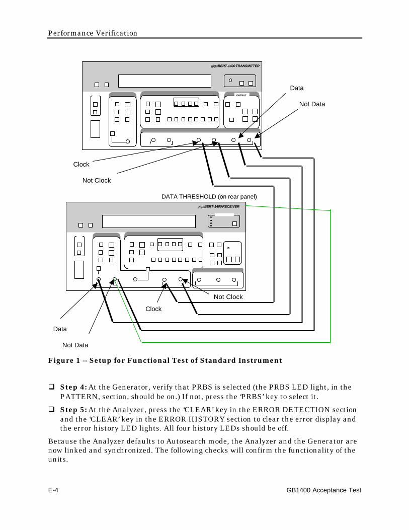
Performance Verification
E-4 GB1400 Acceptance Test
gigaBERT-1400 RECEIVER
OUTPUT
gigaBERT-1400 TRANSMITTER
Clock
Not Clock
Data
Not Data
Data
Not Data
Clock
Not Clock
DATA THRESHOLD (on rear panel)
Figure 1 -- Setup for Functional Test of Standard Instrument
q Step 4: At the Generator, verify that PRBS is selected (the PRBS LED light, in thePATTERN, section, should be on.) If not, press the ‘PRBS’ key to select it.
q Step 5: At the Analyzer, press the ‘CLEAR’ key in the ERROR DETECTION sectionand the ‘CLEAR’ key in the ERROR HISTORY section to clear the error display andthe error history LED lights. All four history LEDs should be off.
Because the Analyzer defaults to Autosearch mode, the Analyzer and the Generator arenow linked and synchronized. The following checks will confirm the functionality of theunits.
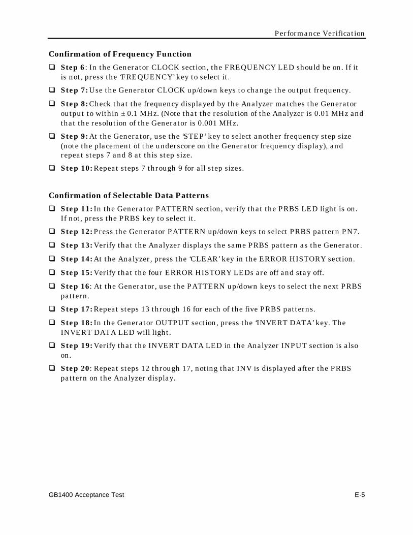
Performance Verification
GB1400 Acceptance Test E-5
Confirmation of Frequency Functionq Step 6: In the Generator CLOCK section, the FREQUENCY LED should be on. If it
is not, press the ‘FREQUENCY’ key to select it.
q Step 7: Use the Generator CLOCK up/down keys to change the output frequency.
q Step 8: Check that the frequency displayed by the Analyzer matches the Generatoroutput to within ± 0.1 MHz. (Note that the resolution of the Analyzer is 0.01 MHz andthat the resolution of the Generator is 0.001 MHz.
q Step 9: At the Generator, use the ‘STEP’ key to select another frequency step size(note the placement of the underscore on the Generator frequency display), andrepeat steps 7 and 8 at this step size.
q Step 10: Repeat steps 7 through 9 for all step sizes.
Confirmation of Selectable Data Patternsq Step 11: In the Generator PATTERN section, verify that the PRBS LED light is on.
If not, press the PRBS key to select it.
q Step 12: Press the Generator PATTERN up/down keys to select PRBS pattern PN7.
q Step 13: Verify that the Analyzer displays the same PRBS pattern as the Generator.
q Step 14: At the Analyzer, press the ‘CLEAR’ key in the ERROR HISTORY section.
q Step 15: Verify that the four ERROR HISTORY LEDs are off and stay off.
q Step 16: At the Generator, use the PATTERN up/down keys to select the next PRBSpattern.
q Step 17: Repeat steps 13 through 16 for each of the five PRBS patterns.
q Step 18: In the Generator OUTPUT section, press the ‘INVERT DATA’ key. TheINVERT DATA LED will light.
q Step 19: Verify that the INVERT DATA LED in the Analyzer INPUT section is alsoon.
q Step 20: Repeat steps 12 through 17, noting that INV is displayed after the PRBSpattern on the Analyzer display.

Performance Verification
E-6 GB1400 Acceptance Test
Confirmation of Generator Output Data Level ChangeIn this part of the functional test procedure, you will verify that the Analyzer thresholdresponds correctly to the sample values of baseline offset and amplitude in theGenerator output. The sample values and threshold limits are summarized in thefollowing Data Levels table. Repeat steps 21 through 27 for each row of the Data Levelstable.
Note
Values in the following table are repeated; the purpose of this test is todetermine that the GB1400 responds correctly to changes in data level. Youdo not need to read the results except at Step 26.
Data Levels
Generator Baseline Offset Generator Amplitude Analyzer Threshold Limits
−1.00 1.00 −0.70 to −0.30
0.00 1.00 0.30 to 0.70
−1.00 2.00 −0.20 to 0.20
q Step 21: Connect the cable to DATA THRESHOLD on the rear panel of theAnalyzer.
q Step 22: In the Generator OUTPUT section, the DATA LED should be on. If not,press the ‘DATA’ key. The INVERT DATA LED should be off. If it is not, press thekey to turn it off.
q Step 23: Use the Generator BASELINE OFFSET up/down keys to set the baselineoffset value shown in the Generator Baseline Offset column of the Data Levels table.
q Step 24: Use the AMPLITUDE up/down keys to set the amplitude to the valueshown in the Generator Amplitude column of the Data Levels table.
q Step 25: At the Generator, select another PRBS pattern (using the PATTERNup/down keys) to initiate a resynchronization by the Analyzer.
q Step 26: Select the PRBS pattern PN7.
q Step 27: At the Analyzer, verify that once the green LOCK LED in the SYNC sectionlights, the displayed threshold is between the limits shown in the AnalyzerThreshold Limits column of the Data Levels table. Cycle through all five PRBSpatterns (PN7, PN15, PN17, PN20, and PN23) and verify that the Analyzersynchronizes on each pattern.
q Step 28: At the Analyzer, press the CLEAR button in the ERROR HISTORY sectionto ensure than the SYNC LOSS LED is off.
Performance Verification
GB1400 Acceptance Test E-7
Confirmation of Error Injection Ratesq Step 29: In the Analyzer ERROR DETECTION section, press the ‘DISPLAY
SELECT’ key until there is an ∞ (infinity) symbol on the display preceding the errorrate.
q Step 30: At the Analyzer, press the ‘CLEAR’ key in the ERROR HISTORY section,and press the ‘CLEAR’ key in the ERROR DETECTION section to clear the historyLEDs and error rate display.
q Step 31: In the Generator ERROR INJECTION section, press the ‘SINGLE’ key andconfirm on the Analyzer the BIT LED (in the ERROR HISTORY section) lights andthat the displayed error total increases by one each time you press the ‘SINGLE’ key.Press this key at least 20 times.
Note
Press the ‘SINGLE’ key briefly. If you hold it down, the Generator injectserrors repeatedly into the data stream.
q Step 32: In the ERROR HISTORY section, press the ‘CLEAR’ key to clear thehistory LEDs.
q Step 33: In Generator ERROR INJECTION section, press the ‘RATE’ key. ERR 1E-7will appear on the display. The ERROR INJECTION LED should be on steadily.
q Step 34: In the Generator ERROR DETECTION section, press the ‘CLEAR’ key toclear the totalize error display.
q Step 35: Wait 15 seconds, then confirm that the error rate displayed on the Analyzermatches the Generator injected error rate and that the Analyzer BIT LED in theERROR HISTORY section is lighted.
q Step 36: In the Generator ERROR INJECTION section, press the ‘RATE’ key once toselect the next error rate.
q Step 37: Repeat steps 33 through 35 until all Generator error rates have beenverified and EXT appears on the Generator display. Press the Generator ‘ERRORRATE’ key once more to turn off error injection.
q Step 38: Look straight at the Generator LCD panel. Depress the VIEW ANGLEbutton until you see the darkest digits. Change the vertical angle from which youview the display and adjust the clarity by depressing the VIEW ANGLE adjustbutton. This is to verify that the contrast of the display can be optimized for theuser’s viewing angle.
q Step 39: Repeat Step 37 for the Analyzer.
q Step 40: Set the Generator and the Analyzer to Factory Default settings. Verify thatthe Analyzer SYNC LOCK light illuminates. Push the CLEAR key in the ERRORHISTORY section. Record the delay value shown on the display (lower left displayarea) for later use. De-select AUTOSEARCH on the Analyzer. Press the ‘DELAY’ keyin the input section of the Analyzer. Vary the delay using the ‘UP’ and ‘DOWN’ arrow
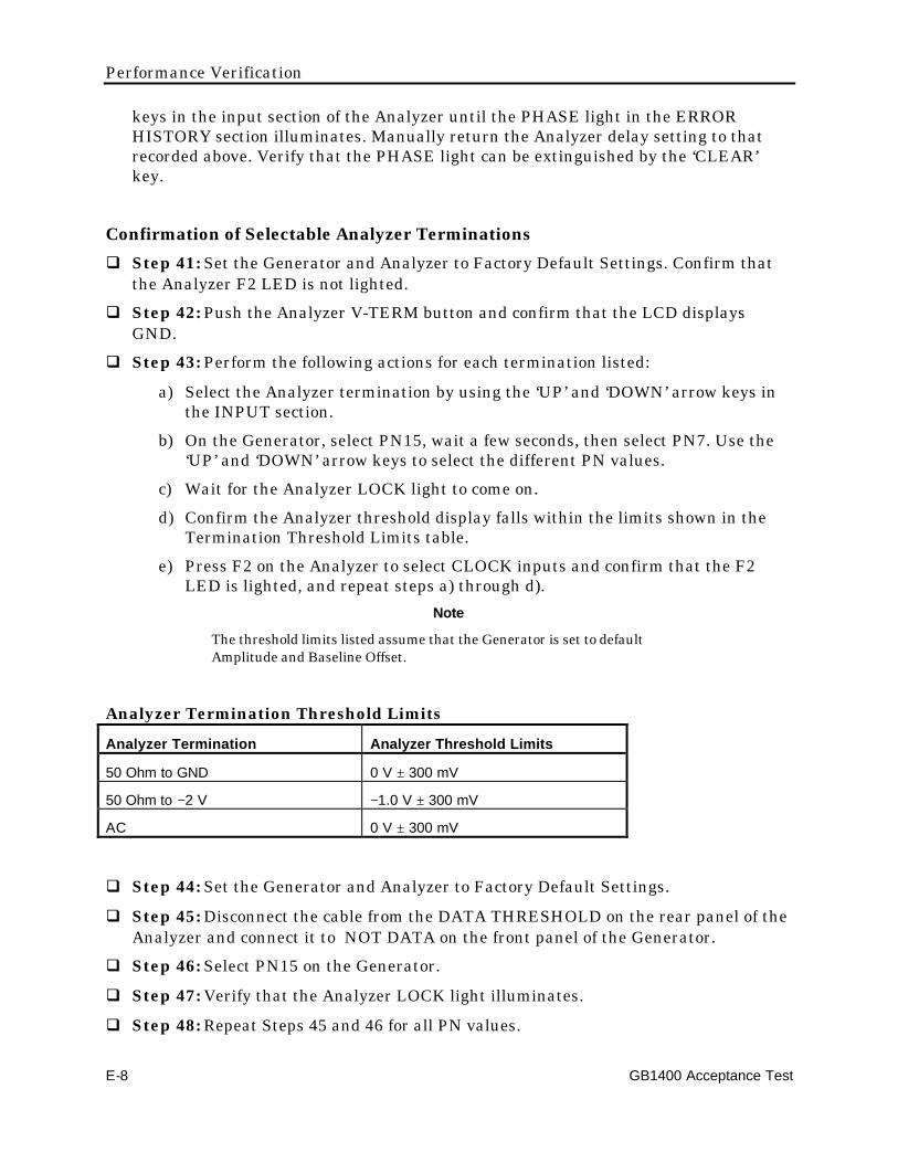
Performance Verification
E-8 GB1400 Acceptance Test
keys in the input section of the Analyzer until the PHASE light in the ERRORHISTORY section illuminates. Manually return the Analyzer delay setting to thatrecorded above. Verify that the PHASE light can be extinguished by the ‘CLEAR’key.
Confirmation of Selectable Analyzer Terminationsq Step 41: Set the Generator and Analyzer to Factory Default Settings. Confirm that
the Analyzer F2 LED is not lighted.
q Step 42: Push the Analyzer V-TERM button and confirm that the LCD displaysGND.
q Step 43: Perform the following actions for each termination listed:
a) Select the Analyzer termination by using the ‘UP’ and ‘DOWN’ arrow keys inthe INPUT section.
b) On the Generator, select PN15, wait a few seconds, then select PN7. Use the‘UP’ and ‘DOWN’ arrow keys to select the different PN values.
c) Wait for the Analyzer LOCK light to come on.
d) Confirm the Analyzer threshold display falls within the limits shown in theTermination Threshold Limits table.
e) Press F2 on the Analyzer to select CLOCK inputs and confirm that the F2LED is lighted, and repeat steps a) through d).
Note
The threshold limits listed assume that the Generator is set to defaultAmplitude and Baseline Offset.
Analyzer Termination Threshold Limits
Analyzer Termination Analyzer Threshold Limits
50 Ohm to GND 0 V ± 300 mV
50 Ohm to −2 V −1.0 V ± 300 mV
AC 0 V ± 300 mV
q Step 44: Set the Generator and Analyzer to Factory Default Settings.
q Step 45: Disconnect the cable from the DATA THRESHOLD on the rear panel of theAnalyzer and connect it to NOT DATA on the front panel of the Generator.
q Step 46: Select PN15 on the Generator.
q Step 47: Verify that the Analyzer LOCK light illuminates.
q Step 48: Repeat Steps 45 and 46 for all PN values.

Performance Verification
GB1400 Acceptance Test E-9

Performance Verification
E-10 GB1400 Acceptance Test
Confirmation of Buttons and Indicatorsq Step 49: Reset both the Generator and Analyzer by cycling the power.
q Step 50: Verify the following Generator LEDs.
Section ON OFF
CLOCK FREQUENCY RECALL
SAVE
EXT
PATTERN PRBS WORD
RECALL
SAVE
WORD LENGTH
F1 - F4
Bits 1 - 8
OUTPUT DATA CLOCK
INVERT DATA
ERROR INJECT RATE
Left Side PANEL LOCK
GPIB ADDR
LOCAL
q Step 51: Verify the Generator LEDs and buttons operate by toggling the followingbuttons and observing the LEDs turn ON and OFF.
Section LED/Button Indicator
Left Side PANEL LOCK
GPIB ADDR
ON - OFF
ON - OFF
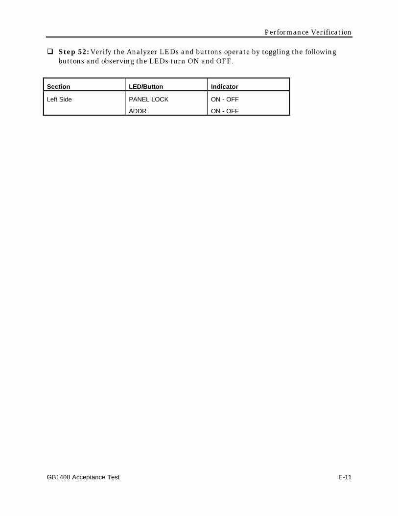
Performance Verification
GB1400 Acceptance Test E-11
q Step 52: Verify the Analyzer LEDs and buttons operate by toggling the followingbuttons and observing the LEDs turn ON and OFF.
Section LED/Button Indicator
Left Side PANEL LOCK
ADDR
ON - OFF
ON - OFF
GB1400 User Manual F-1
Default SettingsThis appendix lists factory default settings for the GB1400 Generator andAnalyzer.
These are the value for the various operating parameters, when the unit leaves thefactory. These settings can be changed by the user, and stored in non-volatileRAM. Should the non-volatile RAM be corrupted (due to battery failure), theunit will reset all settings as listed here and the message 'RAM CORRUPTION'will appear on the display for a few seconds to note that all settings are reset.
Returning to Factory Default Settings
Resetting the unit to Factory Default Settings can be done in two ways: throughfront panel key sequence; or remotely through the GPIB interface.
How to Recall Factory Default Settings
Using Front Panel Controls
Use the following procedure to recall the factory default settings of the Generatoror Analyzer using front panel controls:
1. Turn instrument power off.
2. While holding down the WORD CLEAR, BIT 1, and VIEW ANGLE keyssimultaneously, turn instrument power back on.
3. After you see the message Default Settings appear in the display, release thethree keys. In a few seconds the normal display format will appear and theinstrument will be in its default setup.
Via Remote Control
To return the Generator or Analyzer to its factory default settings via remotecontrol, issue the *rst command. Note that this command also returns theinstrument to the Operation Complete Command Idle State and the OperationComplete Query Idle State. This command does not change the WORD memorycontents.

Default Settings
F-2 GB1400 User Manual
Generator (TX) Factory Default Settings
CLOCK
External Clock Source INT
Frequency 1405.0 MHz
Frequency Memory
0 720 MHz
1 360 MHz
2 180 MHz
3 90 MHz
4 45 MHz
5 1360 MHz
6 680 MHz
7 340 MHz
8 170 MHz
9 85 MHz
Frequency Step Size 1000.0 MHz
Data Pattern
PRBS pattern PN 7 (27-1)
Word memory (all ten) AA 55
Programmable Data Pattern AA 55
Current Pattern Setting PRBS
Data Invert OFF
Word Order LSB
CLOCK/ DATA Outputs
Output Clock Amplitude 1.50 V
Clock Baseline Offset -0.75 V
Output Data Amplitude 1.50 V
Data Baseline Offset -0.75 V
Error Injection Rate OFF

Default Settings
GB1400 User Manual F-3
Remote Interfaces
Remote mode local
GPIB address (Generator) 15
GPIB Bus TALK_LISTEN
GPIB terminator EOI/LF
RS-232C prompt BERT1400>
RS-232C baud rate 9600
RS-232C parity even
RS-232C data size 8 bits
RS-232C EOL CR/LF
RS-232C echo OFF
RS-232C prompt line feed OFF
MISC.
View Angle 0
Panel Lock OFF
Response Header ON

Default Settings
F-4 GB1400 User Manual
Analyzer (RX) Factory Default Settings
Clock, Data, and Reference Data Inputs
Input data delay 0 pS
Input data threshold 0.00 volts
Reference Data Delay 0 pS
Reference Data Threshold -1.50 V
Data Termination GND
Clock Termination GND
Reference Data Termination GND
Data Pattern
PRBS pattern PN 7 (27-1)
Word memory (all ten) AA 55
Programmable Data Pattern AA 55
Current Pattern Setting PRBS
Data Invert OFF
Reference Data Mode OFF
Word Order LSB
Auto Search/Pattern Synchronization
Auto Search ON
Auto Search Delay Mode FAST
Auto Search Data Samples 10E+7
Auto Search Data BER Threshold 10E-6
Synchronization Disable OFF
Error display select mode TOT
Error Beeper
Audio volume 0 (off)
Audio error rate threshold 1E-3
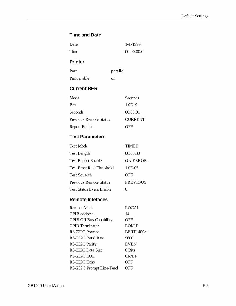
Default Settings
GB1400 User Manual F-5
Time and Date
Date 1-1-1999
Time 00:00:00.0
Printer
Port parallel
Print enable on
Current BER
Mode Seconds
Bits 1.0E+9
Seconds 00:00:01
Previous Remote Status CURRENT
Report Enable OFF
Test Parameters
Test Mode TIMED
Test Length 00:00:30
Test Report Enable ON ERROR
Test Error Rate Threshold 1.0E-05
Test Squelch OFF
Previous Remote Status PREVIOUS
Test Status Event Enable 0
Remote Intefaces
Remote Mode LOCALGPIB address 14GPIB Off Bus Capability OFFGPIB Terminator EOI/LFRS-232C Prompt BERT1400>RS-232C Baud Rate 9600RS-232C Parity EVENRS-232C Data Size 8 BitsRS-232C EOL CR/LFRS-232C Echo OFFRS-232C Prompt Line-Feed OFF

Default Settings
F-6 GB1400 User Manual
MISC.
View Angle 0
Panel Lock OFF
Response Header ON
GB1400 User Manual G-1
Cleaning InstructionsClean the GB1400 often enough to prevent dust and dirt from accumulating. Dirtacts as a thermal insulator, preventing effective heat dissipation, and can alsoprovide high-resistance leakage paths between conductors or components in ahumid environment.
Cleaning the Exterior
Clean the dust from the outside of the instrument with a soft, clean cloth or smallbrush. A brush is especially useful for removing dust from around the buttonsand connectors. Remove hardened dirt with a soft cloth dampened with a milddetergent and water solution. Do not use abrasive cleaners.
Cleaning the CRT
Clean the light filter and CRT face with a soft, lint-free cloth dampened withdenatured alcohol. Do not use abrasive cleaners.
Cleaning the Interior
Interior cleaning and maintenance should be performed by qualified servicepersonnel only.

Cleaning Instructions
G-2 GB1400 User Manual
GB1400 User Manual H-1
Pattern Editor Requirements and Features
Version 1.10 (9/13/96)
Before You Begin:
Before installing this program, it is suggested that you make a copy of this diskand store it away in a safe place. To protect against accidentally overwriting anyfiles on this disk, slide the write protect tab on the back of the disk to the protectposition.
To Install MLPE:
1) Start Microsoft Windows.
2) In the FILE pulldown menu, choose RUN.
3) Type A:\SETUP or B:\SETUP.
4) Choose the OK button.
5) The program will install and create a new Program Manager group.
6) The README document is this document.
7) The installation is complete.
What is MLPE?
MLPE is a specialized pattern editor that can be used with TektronixgigaBERT700/1400 series and packetBERT200 BERT products. It allows theuser to create, store, edit, and transfer user defined and created patterns to andfrom the BERTS.
Patterns can be created in several different formats and easily converted from oneformat to another. The editor allows multiple files to be open at a time to makeediting and transferring data between files easier. See the list of featuresdescribed later in this document.
Pattern Editing Software
H-2 GB1400 User Manual
Minimum Requirements:
Microsoft Windows 3.1 or later running on a 386 or faster machine with 4 Mb ofmemory, For reasonable speed, a 486 DX or DX2 with at least 8 Mb of memory.
At least 2 Mb of free hard disk space.
gB700 Tx or Rx with 128K memory.
gB1400/1600 Tx or Rx with at least 256K memory.
A PB200.
One free RS-232 port or a National Instruments GPIB card with associated driverand software.
List of Features
• Editing capability in excess of 1 Mb. File size is in increments of 1 bit.
• Files can be displayed, edited, and saved in Hex, Decimal, Octal, or Binaryformats.
• Data can be saved or displayed LSB (Least Significant Bit) or MSB (MostSignificant Bit) first.
• Files saved in one format can be converted to any of the other three formats.
• Multiple editing windows can be open simultaneously to allow working onseveral files at once.
• The editor runs under Microsoft Windows with full Windows printingcapability.
• Extensive built-in help.
• Data can be uploaded to a gB700/1400/1600 Tx or Rx via RS-232 or GPIB.
• Uploaded data can be saved in any memory location for any memoryconfiguration, even while the instrument is performing tests.
• Data can be downloaded from a gB700/1400 Tx or Rx via RS-232 or GPIB.Downloaded data can be saved to disk for safe keeping or later editing, evenwhile the instrument is performing tests.
• Data can be saved to disk and read from disk in a format compatible with thePB200, both current single file per disk and future multiple files per diskformats.
• The editor has full cut, paste, and copy facilities along with a last actiondelete UNDO.
• The editor has full find and replace functions.
• Replaced data can be a different length than the data it is replacing.
What the editor cannot do:

Pattern Editing Software
GB1400 User Manual H-3
• The editor uses a proprietary editor and therefore cannot share data withother applications via the Clipboard.
• The editor will not work with the GB660.
List of Files on this Disk
SETUP.EXE
SETUP.INS
README.DOC
MLPE.Z
MLPE.INI
MLPE.BMP
FPGRID10.VBX
Please verify that the above files are on this disk. If any are missing, pleasecontact Tektronix.
If you are using an alternate shell, such as Norton Desktop
In some cases the program will not install properly if an alternate shell, such asNorton Desktop is used as your Windows shell. If the program gives errormessages, try installing the program using the standard WindowsPROGMAN.EXE shell. If the installation proceeds normally without any errorsbut the program fails to run properly, check the following:
If you are using Norton Desktop 3.0, in the Tektronix program group select(single mouse click) the Pattern Editor icon and then select PROPERTIES in theGROUP menu. Select the ADVANCED icon. If the default path and directorywas chosen for installation, see if the listed STARTUP DIRECTORY shown is:
(drive on which Windows is installed):\MLPE\
If there is a "\" after MLPE then edit the entry to remove it.
The correct entry should look like the following:
(drive on which Windows is installed):\MLPE
Choose OK
The same may have to be done for the README icon if an error messageindicating that the README cannot be found.
The program will run properly now.
If the program should stop working
If the program has been installed and was working properly and then at a latertime fails to run properly, check to see if the "MLPE.INI" file in the WINDOWS
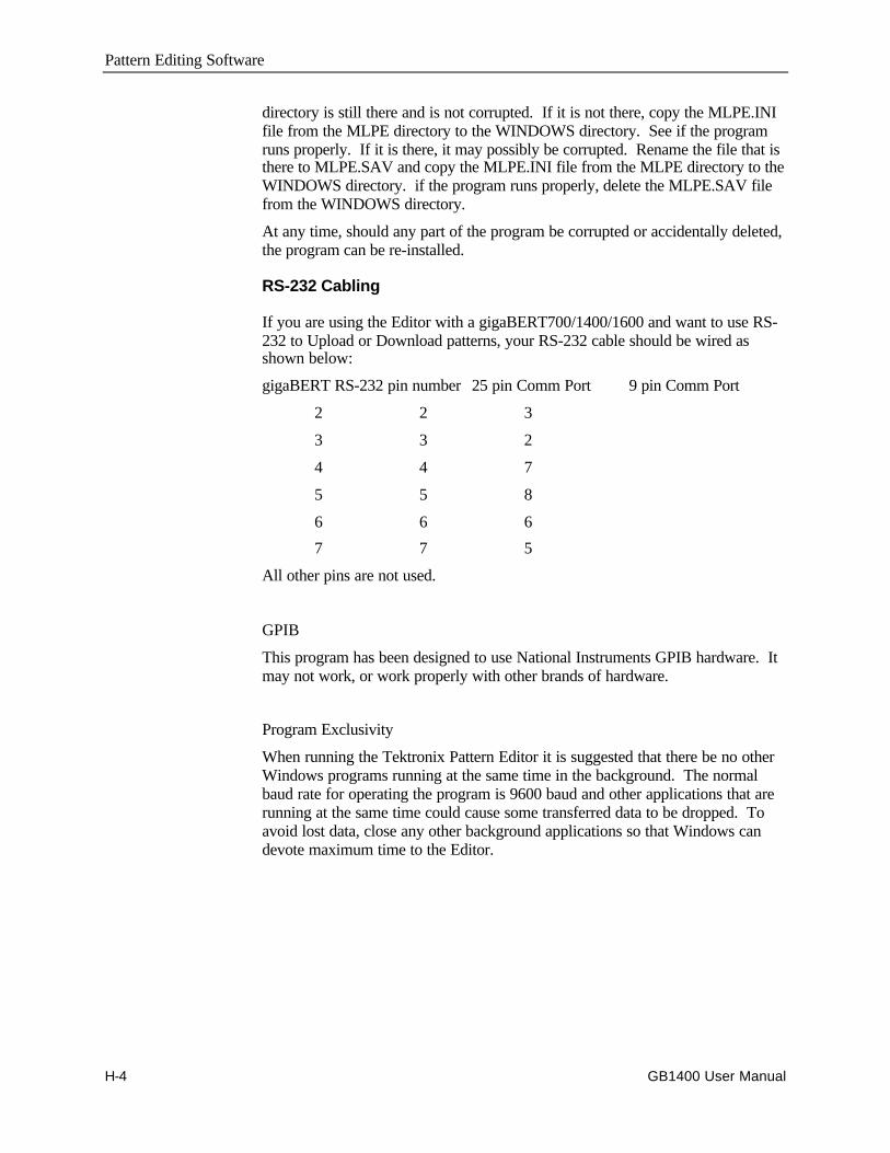
Pattern Editing Software
H-4 GB1400 User Manual
directory is still there and is not corrupted. If it is not there, copy the MLPE.INIfile from the MLPE directory to the WINDOWS directory. See if the programruns properly. If it is there, it may possibly be corrupted. Rename the file that isthere to MLPE.SAV and copy the MLPE.INI file from the MLPE directory to theWINDOWS directory. if the program runs properly, delete the MLPE.SAV filefrom the WINDOWS directory.
At any time, should any part of the program be corrupted or accidentally deleted,the program can be re-installed.
RS-232 Cabling
If you are using the Editor with a gigaBERT700/1400/1600 and want to use RS-232 to Upload or Download patterns, your RS-232 cable should be wired asshown below:
gigaBERT RS-232 pin number 25 pin Comm Port 9 pin Comm Port
2 2 3
3 3 2
4 4 7
5 5 8
6 6 6
7 7 5
All other pins are not used.
GPIB
This program has been designed to use National Instruments GPIB hardware. Itmay not work, or work properly with other brands of hardware.
Program Exclusivity
When running the Tektronix Pattern Editor it is suggested that there be no otherWindows programs running at the same time in the background. The normalbaud rate for operating the program is 9600 baud and other applications that arerunning at the same time could cause some transferred data to be dropped. Toavoid lost data, close any other background applications so that Windows candevote maximum time to the Editor.
Pattern Editing Software
GB1400 User Manual H-5
Saving patterns
If you open an existing saved pattern from disk and make changes to it, you willbe reminded to save the changes before you can close the file or exit the program.If you receive a pattern from a gigaBERT to the Tektronix Pattern Editor youmust remember to save the file to disk before closing the file or exiting theprogram. The program will not remind you to do so.
Depending on the format selected, if you attempt to save a file with any cells notcompletely filled, the Editor will automatically insert zeros to complete the cell.For example, if the HEX format is chosen and the last cell has an entry of "5", theeditor will save the cell with an entry of "05".
If a pattern of more or less than whole bytes is saved, the partial byte will besaved with a whole byte entry whose needed bits are correct and the excess beingset to zero(s).
The BACKSPACE key works only within a cell.
Sending Patterns to or from a gigaBERT
Although you can save a pattern with a bit order of either LSB or MSB, you mustset the gigaBERT separately to reflect the correct order. The program does notautomatically set, or read, the gigaBERT to match the order of the file being sent.
If you should have a problem sending a pattern to a gigaBERT or receiving apattern from a gigaBERT, there may be a problem with the identification stringthat is stored in the gigaBERT. Please consult the remote commands section ofthe respective manual for the instrument. Normally, unless you change theidentification strings and prompt, they will remain at the default setting.
Another method for restoring the correct gigaBERT identification string andprompt is to revert the gigaBERT to its default factory configuration. Revertingthe instrument to its default condition will destroy any saved patterns and clockfrequencies (Tx). To do this, turn the instrument off and then do the following:
For the gB1400 Transmitter: Simultaneously hold in the OUTPUT Clock andPATTERN Clear buttons and turn the instrument on.
For the gB1400 Receiver: Simultaneously hold in the ERROR DETECTIONClear and PATTERN Clear buttons and turn the instrument on.
For the gB700 Transmitter or Receiver: Simultaneously hold in the PATTERNMSB, PATTERN Clear, and VIEW ANGLE buttons and turn the instrument on.
Hold the buttons in until RAM CORRUPTION or DEFAULT SETTING showsin the display. Retry sending or receiving a pattern.
For help
Double click on the Context Help icon (The arrow and ?).
Corrections to the HELP information
Pattern Editing Software
H-6 GB1400 User Manual
The HELP system indicates that only "filename.pat" files can be opened. This isnot true. Although ".pat" is the default extension and should be used for savingall gigaBERT files, there may be different extensions that may be used for thepacketBERT200 depending on the version of firmware of the instrument. Allpossible filename extensions are listed in the "List of File Type" box in the FileOpen and File Save menus. Consult your packetBERT200 manual for filenamesthat are valid.
To Remove the Tektronix Pattern Editor
1) Start Windows and remove the Tektronix group and all of its entries.
2) Save the configuration.
3) Open File Manager
4) Delete the following:
The MLPE directory and PATTERNS sub directory and all entries ineach.
Delete the MLPE.INI file in the WINDOWS directory.
5) The program edits the PATH statement in the AUTOEXEC.BAT file to addthe WINDOWS\SYSTEM directory to the path. You can edit the file to removethis statement, or leave it.
There are no other files or changes made by the program.
NOTE:
For technical support or questions pertaining to the installation of this program,call Tektronix at 800-643-2167 or 978-256-6800.
Microsoft Windows is a trademark of Microsoft Corporation.
National Instruments is a trademark of National Instruments Corporation.

Pattern Editing Software
GB1400 User Manual H-7
WARNINGRead License Agreement Before OpeningTektronix / Microwave Logic ProductsCopyright Microwave Logic, Inc. All Rights ReservedPart Number 9508-1388Version 1.0IMPORTANTREAD BEFORE OPENING SEALED WRAPPER
This software is provided under license from Microwave Logic, Inc. Retention of this program for morethan (30) days, use of the program in any manner, or opening the sealed wrapper surrounding theprogram constitutes acceptance of the license terms.
CAREFULLY READ THE ENCLOSED SOFTWARE LICENSE AGREEMENTBEFORE OPENING THE SEALED WRAPPER SURROUNDING THE PROGRAM.If you cannot agree to the license terms, promptly return the unopened package to Microwave Logic for afull refund. Contact the nearest Microwave Logic Field Office for return assistance.
Copyright 1995 Microwave Logic, inc. Unpublished-rights reserved under the copyright laws of theUnited States RESTRICTED RIGHTS LEGEND Use, duplication, or disclosure by the U.S. Government issubject to restrictions as set forth in subparagraph (b)(2) of the Technical Data and Computer SoftwareCommercial Items clause at DFARS252. 211-7015, or in subparagraph (c)(2) of the CommercialComputer Software-Restricted Rights clause at FAR 52.277-19, as applicable . Microwave Logic, Inc. 285Mill Road, Chelmsford, MA 01824.
Pattern Editing Software
H-8 GB1400 User Manual
TEKTRONIX, MICROWAVE LOGIC PRODUCTSSOFTWARE LICENSE AGREEMENT
THE ENCLOSED PROGRAM IS FURNISHED SUBJECT TO THE TERMS AND CONDITIONS OF THISAGREEMENT, RETENTION OF THE PROGRAM FOR MORE THAN THIRTY DAYS, OPENING THESEALED WRAPPER, IF ANY, SURROUNDING THE PROGRAM OR USE OF THE PROGRAM IN ANYMANNER WILL BE CONSIDERED ACCEPTANCE OF THE AGREEMENT TERMS. IF THESE TERMSARE NOT ACCEPTABLE, THE UNUSED PROGRAM AND ANY ACCOMPANYINGDOCUMENTATION SHOULD BE RETURNED PROMPTLY TO MICROWAVE LOGIC, INC. FOR AFULL REFUND OF THE LICENSE FEE PAID.
DEFINITIONS: "Microwave Logic" means Microwave Logic, Inc. a Delaware corporation, with respect toa Program acquired by Customer in the United States, with respect to a program acquired by Customer inCanada."Program" means the Microwave Logic software product (executable program and/or data) enclosed withthis Agreement or included within the equipment with which this Agreement is packed."Customer" means the person or organization in whose name the Program was ordered.
LICENSE. Customer may:a. Use the Program under a nontransferable license on a single specified machine.b. Copy the Program for archival or backup purposes, provided that no
more than one (1) such copy is permitted to exist at any one time.Each copy of the Program made by Customer must include a reproduction ofany copyright notice or restrictive rights legend appearing in or on the copy ofthe Program as received from Microwave Logic.
Customer may not:a. Transfer the Program to any person or organization outside of Customer
or the corporation of which Customer is a part without the prior writtenconsent of Microwave Logic.
b. Export or re-export, directly or indirectly, the program, any associateddocumentation, or the direct product thereof, to any country to whichsuch export or re-export is restricted by law or regulation of the UnitedStates or any foreign government having jurisdiction without theprior authorization, if required, of the Office of Export Administration,Department of Commerce, Washington, D.C. and the correspondingagency of such foreign government.
c. For object-code Programs only, reverse compile or disassemble theProgram for any purpose; or
d. Copy the documentation accompanying the Program.
For Programs designed to reside on a single-machine and support one ormore additional machines, either locally or remotely, without permitting the Program to be transferred toan additional machine for local execution, the additional machines shall be considered within thedefinition of "single machine". For programs permitting the Program to be transferred to an additionalmachine for local execution, a separate license shall be required for each such machine with which theProgram may be used.Title to the Program and all copies thereof, but not the media on which the Program or copies may resideshall be and remain with Microwave Logic.Customer shall pay when due all property taxes that may now or hereafter be imposed, levied orassessed with respect to the possession or use of the Program or this license and shall file all reportsrequired in connection with such taxes.Any portion of the Program modified by Customer or merged with another program shall remain subject tothese terms and conditions.

Pattern Editing Software
GB1400 User Manual H-9
If the Program is acquired by or for an agency of the U.S. Government, the Program shall be consideredcomputer software developed at private expense and the license granted herein shall be interpreted asgranting Customer restricted rights in the Program and related documentation as defined in the applicableacquisition regulation.THE PROGRAM MAY NOT BE USED, COPIED, MODIFIED, MERGED, OR TRANSFERRED TOANOTHER EXCEPT AS EXPRESSLY PERMITTED BY THESE TERMS AND CONDITIONS.UPON TRANSFER OF ANY COPY, MODIFICATION, OR MERGED PORTION OF THE PROGRAM,THE LICENSE GRANTED HEREIN IS AUTOMATICALLY TERMINATED.TERM. The license granted herein is effective upon acceptance by Customer,and shall remain in effect until terminated as provided herein. The License may be terminated byCustomer at any time upon written notice to Microwave Logic The license may be terminated byMicrowave Logic or any third party from whom Microwave Logic may have obtained a respective licensingright if Customer fails to comply with any term or condition and such failure is not remedied within thirty(30) days after notice thereof from Microwave Logic or such third party. Upon termination by either party,Customer shall return to Microwave Logic, the Program and all associated documentation, together withall copies in any form.LIMITED WARRANTY. Microwave Logic warrants that the media on which the Program is furnished andthe encoding of the Program on the media will be free from defects in materials and workmanship for aperiod of three (3) months from the date of shipment. If any such medium or encoding proves defectiveduring the warranty period, Microwave Logic will provide a replacement in exchange for the defectivemedium. Except as to the media on which the Program is furnished, the Program is provided "as is"without warranty of any kind, either express or implied. Microwave Logic does not warrant that thefunctions contained in the Program will meet Customer's requirements or that the operation of theProgram will be uninterrupted or error-free.In order to obtain service under this warranty, Customer must notify Microwave Logic of the defect beforethe expiration of the warranty period. If Microwave Logic is unable to provide a replacement that is freefrom defects in materials and workmanship within a reasonable time thereafter, Customer may terminatethe license for the Program and return the Program and any associated materials for credit or refund.
Pattern Editing Software
H-10 GB1400 User Manual
THIS WARRANTY IS GIVEN BY MICROWAVE LOGIC WITH RESPECT TO THE PROGRAM IN LIEUOF ANY OTHER WARRANTIES, EXPRESS OR IMPLIED. MICROWAVE LOGIC AND ITS VENDORSDISCLAIM ANY IMPLIED WARRANTIES OF MERCHANTABILITY OR FITNESS FOR A PARTICULARPURPOSE., MICROWAVE LOGIC'S RESPONSIBILITY TO REPLACE DEFECTIVE MEDIA, ORREFUND CUSTOMER'S PAYMENT IS THE SOLE AND EXCLUSIVE REMEDY PROVIDED TO THECUSTOMER FOR BREACH OF THIS WARRANTY.
LIMITATION OF LIABILITY, IN NO EVENT SHALL MICROWAVE LOGIC OR OTHERS FROM WHOMMICROWAVE LOGIC HAS OBTAINED A LICENSING RIGHT BE LIABLE FOR ANY INDIRECT,SPECIAL, INCIDENTAL, OR CONSEQUENTIAL DAMAGES ARISING OUT OF OR CONNECTEDWITH CUSTOMER'S POSSESSION OR USE OF THE PROGRAM, EVEN IF MICROWAVE LOGIC ORSUCH OTHERS HAS ADVANCE NOTICE OF THE POSSIBILITY OF SUCH DAMAGES.THIRD-PARTY DISCLAIMER. Except as expressly agreed otherwise, third parties from whomMicrowave Logic may have obtained a licensing right do not warrant the program, do not assume anyliability with respect to its use, and do not undertake to furnish any support or information relating thereto.GENERAL. This Agreement contains the entire agreement between the parties with respect to the use,reproduction, and transfer of the Program.Neither this Agreement nor the license granted herein is assignable or transferable by Customer withoutthe prior written consent of Microwave Logic.This Agreement and the license granted herein shall be governed in the United States by the laws of theState of Delaware.All questions regarding this Agreement or the license granted herein should be directed in the UnitedStates to the nearest Microwave Logic Sales Office.
GB1400 User Manual I-1
Theory of OperationSee block diagrams of GB1400 TX and GB1400 RX at end of this section.
GB1400 Generator (TX)
Design Overview
The GB1400 TX is designed to generate a programmable WORD of 16-bits , andfive PRBS of 2n-1 (n=7, 15, 17, 20, 23), at serial data rates of up to 1400 Mb/s.The unit incorporates a programmable crystal-locked clock source that operatesat this bandwidth, and two programmable pulse output amplifiers, for both Clockand Data Output.
Very high frequency GaAs, ECL and discrete circuitry is incorporated onmultilayer controlled impedance printed circuit boards. RF shielding andcritically timed coaxial cables provide wideband operation with sub-nanosecondtiming. An embedded CPU controls the programmable clock source, high-speeddata generator hardware, programmable WORD loading, remote RS-232C andGPIB interfaces, and soft front panel control.
PLL Clock Source PCB
The PLL Clock Source PCB contains the circuitry to generate and distribute theinternal clock signals. The clock source consists of a PLL (Phase Locked Loop)controlling two VCOs (Voltage Controlled Oscillator). A microprocessorprograms the loop prescale divider ratios.
Data Generator PCB
The Data Generator PCB contains the circuitry required to generate the PRBSpattern, programmable WORD, clock distribution, error inject circuitry, andpattern sync generator.
The PRBS data generator utilizes a pattern dependent, n-length shift register(where of 2n-1 ) with modulo-2 feedback, to generate the desired PRBS pattern.
The shift register operates at 1/2 the system clock frequency. The half-rate data issplit into two phase shifted rails - one is reference, the other is delayed half aframe. These two rails are available at the rear panel, as "Phase A", and "PhaseB". Internally they are multiplexed together to generate the full rate data output.
The programmable WORD is level shifted from TTL to ECL and loaded intoECL registers, then multiplexed and clocked out in a serial stream at full-rate.The 16-bits are loaded at full rate, allowing immediate change to the data pattern.
In PRBS mode, the Pattern Sync circuit detects the start (n, 1, zeros) of the PRBSpattern. This produces a single bit width pulse once per pattern frame. In WORDmode, the shift register detects the programmable WORD load pulse, whichoccurs once per WORD frame.
Theory of Operation
I-2 GB1400 User Manual
The Error Inject circuitry consists of a chain of decade counters, used to generatea pulse every 10E-n bits (where n=3-7). This pulse generates a single bit error onthe output data streams, providing a known error rate for back-to-back tests.
Data and Clock Output Amplifier PCB
The Data stream generated on the Data Generator PCB is sent to the Output AmpPCB, relatched into a flip flop, and differentially driven into a monolithic GaAspulse amplifier which drives the front panel DATA and DATA invert outputs.The amplifier provides adjustment, controlled by DACs, of the Data outputAmplitude and baseline Offset. The amplifier will drive 2 Volts peak-to-peakinto a 50 Ohm load, unterminated 4 Volts peak-to-peak, suitable for Fast TTLand CMOS.
The System Clock signal is sent to the Output Amp PCB, distributed to the Datalatch and also to a discrete GaAs FET pulse amplifier which drives the frontpanel CLOCK and CLOCK invert outputs. The amplifier provides adjustment,controlled by DACs, of the Data output Amplitude and baseline Offset. Theamplifier will drive 2 Volts peak-to-peak into a 50 Ohm load, unterminated 4Volts peak-to-peak, suitable for Fast TTL and CMOS.
Theory of Operation
GB1400 User Manual I-3
GB1400 Analyzer (RX)
Design Overview
The GB1400 RX is designed to receive a differential or single-endedprogrammable WORD of 16-bits, and five PRBS of 2n-1 (n=7, 15, 17, 20, 23), atserial data rates of up to 1400 Mb/s, compare it to a locally-generated identicaldata stream and perform Bit Error Rate (BER) analysis upon it.
Very high frequency GaAs, ECL and discrete circuitry is incorporated onmultilayer controlled impedance pretend circuit boards. RF shielding andcritically timed coaxial cables provide wideband operation with sub-nanosecondtiming. An embedded CPU controls the high-speed data generator hardware,programmable WORD loading, error counter calculations, AUTO SEARCHparameters, remote RS-232C and GPIB interfaces, and soft front panel control.
Input Amplifier PCB
The Input Amp PCB contains the circuitry required to receive differential/ single-ended Data and Clock, and single-ended Reference Data signals. The signals areprovided with selectable termination voltages, variable threshold level and phasedelay between CLOCK and DATA to accommodate DUT (Device-Under-Test)skew. Delay and Input Threshold are controlled by the CPU either automaticallyin AUTO SEARCH mode, or manually through front panel control.
Data Generator PCB
The Data Generator PCB contains the circuitry required to generate the localPRBS pattern or programmable WORD for comparison with the received pattern.The locally-generated pattern is compared bit-by-bit at full rate. The differencesare "Bit Errors" and are counted by the Error Counter PCB.
When the Bit Error Rate (BER) exceeds the SYNC threshold (25% in PRBS,3.1% in WORD mode, variable with 1 Mbit WORD option), the Data GeneratorPCB initiates the synchronization process, by feed-forward technique onincoming PRBS data, or clock-slip technique on programmable WORD data.Once synchronization is established BER measurements begin.
The PRBS data generator utilizes a pattern dependent, n-length shift register(where of 2n-1 ) with modulo-2 feedback, to generate the desired PRBS pattern.
The shift register operates at 1/2 the system clock frequency. The half-rate data issplit into two phase shifted rails - one is reference, the other is delayed half aframe. These two rails are available at the rear panel, as "Phase A", and "PhaseB". Internally they are multiplexed together to generate the full rate data output.
The programmable WORD is level shifted from TTL to ECL and loaded intoECL registers, then multiplexed and clocked out in a serial stream at full-rate.The 16-bits are loaded at full rate, allowing immediate change to the data pattern.
Theory of Operation
I-4 GB1400 User Manual
In PRBS mode, the Pattern Sync circuit detects the start (n, 1, zeros) of the PRBSpattern. This produces a single bit width pulse once per pattern frame. In WORDmode, the shift register detects the programmable WORD load pulse, whichoccurs once per WORD frame.
Error Counter PCB
The Error Counter PCB contains the circuitry to count the Bit Errors detected bythe Data Generator PCB, and also measures the system clock frequency. A BitError Rate (BER) is defined as a ratio of errors/bits, the CPU divides the totalerrors by the total bits, and displays the quotient on the front panel LCD as BER.Total bit errors are also displayed, along with frequency. All counting is done atfull rate, latched and calculated by the CPU.
Common to both GB1400 TX and GB1400 RX
CPU PCB
The CPU PCB contains the CPU, RAM and software PROMs. The 80188microprocessor handles all inter-board communication, storage and loading ofthe programmable 16-bit WORD error counting and frequency calculations,internal clock PLL control and scale calculations, front panel interface andremote communication over the RS-232C and GPIB interfaces. Battery-backupRAM provides storage of ten programmed data patterns, ten programmed clockfrequencies error status, and unit operating status after power loss.
Front Panel PCB
The front panel PCB provides user control of the unit, and contains the keydecoders, LED drivers and 2 x 24 liquid crystal display.
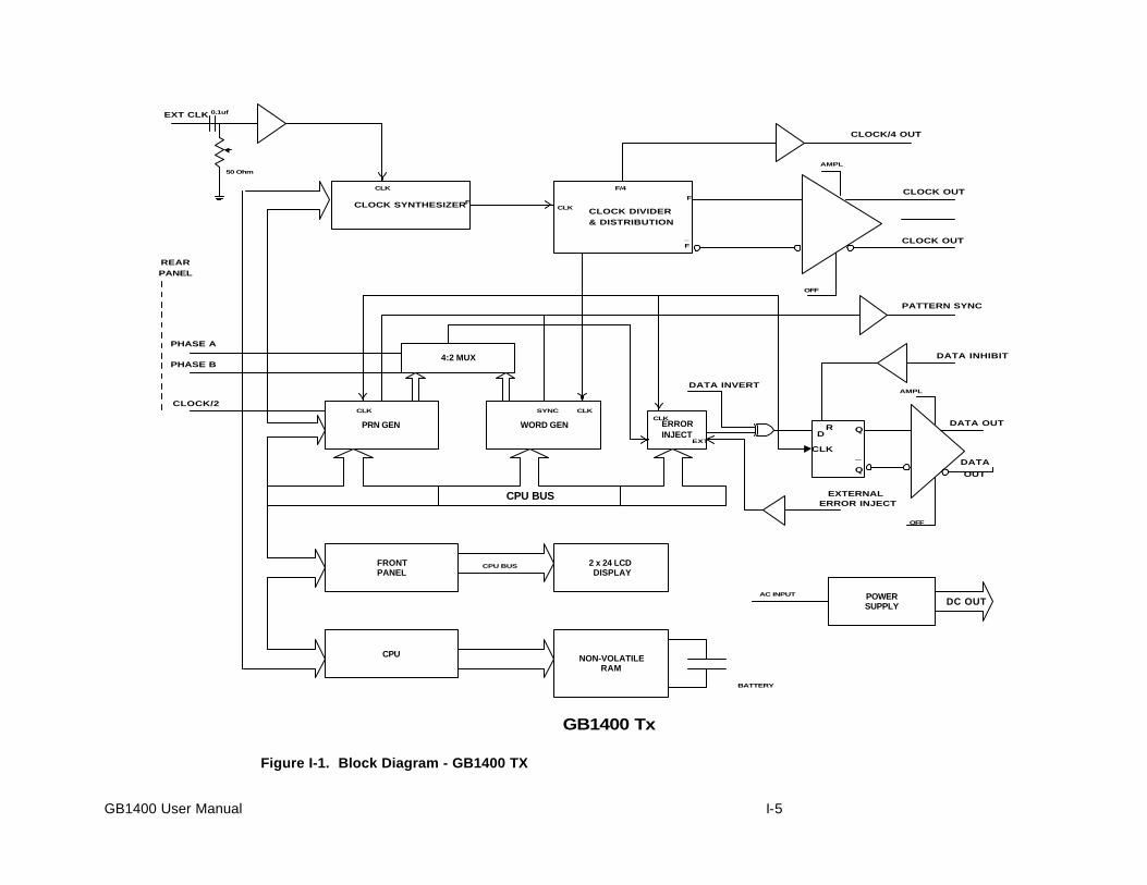
GB1400 User Manual I-5
CLOCK SYNTHESIZERCLOCK DIVIDER
& DISTRIBUTION
EXT CLK
CLOCK/4 OUT
CLOCK OUT
CLOCK OUT
AMPL
OFF
PRN GEN
4:2 MUX
WORD GEN ERRORINJECT
PATTERN SYNC
DATA INVERT
DATA
OUT
OFF
AMPL
DATA OUT
DATA INHIBIT
CPU BUS EXTERNAL
ERROR INJECT
FRONTPANEL
2 x 24 LCDDISPLAY
CPU NON-VOLATILERAM
POWERSUPPLY DC OUT
AC INPUT
PHASE A
PHASE B
REAR
PANEL
BATTERY
CLK
CLK
CLK CLK
CLK
CLK
SYNC
EXTD
Q
Q
R
_
CPU BUS
CLOCK/2
GB1400 Tx
0.1uf
50 Ohm
F
FF
_
F/4
Figure I-1. Block Diagram - GB1400 TX
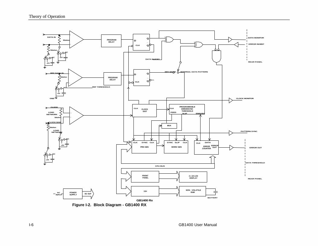
Theory of Operation
I-6 GB1400 User Manual
PROGRAMDELAY
DATA IN DATA MONITOR
ERROR INHIBIT
PROGRAMDELAY
DATA INVERT
REF MODEREF DATA IN
CLOCKDIST
PROGRAMMABLEERROR/SYNCTHRESHOLD
CLOCK MONITOR
CLK
CLK
CLK
INTERNAL DATA PATTERN
CLK
MUX
PRN GEN
FEEDSLIP ERRORS
WORD GEN ERRORCOUNTER
SYNCCLK CLK SYNC SLIP CLK CLK DATA
PATTERN SYNC
ERROR OUT
ERROROUT
FRONTPANEL
2 x 24 LCDDISPLAY
cpu NON - VOLATILERAMPOWER
SUPPLY
CPU BUS
DC OUT
CLOCK
AC
INPUT
BATTERY
DATA THRESHOLD
REAR PANEL
REAR PANEL
50ohm
50ohm
-2V
-2V
AC
50ohm
-2V
GND
CLOCK BAR
LOAD
NETWORK
LOADNETWORK
AC
-2V
AC
50ohm
50ohm
-2V
AC
AC REF THRESHOLD
+
-
+
-
+
-
DQ
Q
_
D Q
Q
_
GB1400 Rx
Figure I-2. Block Diagram - GB1400 RX

Glossary/ Index

GB1400 User Manual glossary-1
GlossaryAddress
A number specifying a particular user device attachment point... The location ofa terminal, a peripheral device, a node, or any other unit or component in anetwork...A set of numbers than uniquely identifies something - a location incomputer memory, a packet of data traveling through a network.
Analog-to-Digital Converter
A device that converts an analog signal, that is, a signal in the form of acontinuously variable voltage or current, to a digital signal, in the form of bits.
Attenuation
A decrease in magnitude of current, voltage, or power of a signal in transmissionbetween points.
Attenuator
An electronic transducer, either fixed or adjustable, that reduces the amplitude ofa wave without causing significant distortion.
Bandwidth
The difference between the limiting frequencies of a continuous frequencyspectrum. The range of frequencies handled by a device or system.
BER
An acronym for Bit Error Ratio (or Rate). The principal measure of quality of adigital transmission system. BER is defined as:
BER = Number of Errors/Total Number of Bits
BER is usually expressed as negative exponent. For example, a BER of 10-7
means that 1 bit out of 107 bits is in error.
BER Floor
A limiting of the bit-error-ratio (BER) in a digital fiber optic system as a functionof received power due to the presence of signal degradation mechanisms ornoise.
Binary
A numbering system that allows only two values, zero and one, (0 and 1). Binaryis the way most computers store information., in combination of ones and zeros.Voltage on. Voltage off. See also: Bit.
Bit
A binary digit, the smallest element of information in binary system. A 1 or 0 ofbinary data.
Bit Error
An incorrect bit. Also known as a coding violation.
Glossary
glossary-2 GB1400 User Manual
Bit Rate
The number of bits of data transmitted over a phone line per second.
Byte
A unit of 8 bits.
Channel
A communications path or the signal sent over a channel. Through multiplexingseveral channels, voice channels can be transmitted over an optical channel.
Clock
1. An electronic component that emits consistent signals that paces a computer’soperations. 2. An oscillator-generated signal that provides a timing reference fora transmission link. A clock provides signals used in a transmission system tocontrol the timing of certain functions, such as the duration of signal elements orthe sampling rate. It also generates periodic, accurately spaced signals used forsuch purposes as timing, regulation of the operations of a processor, orgeneration of interrupts. A clock has two functions: to generate periodic signalsfor synchronization on a transmission facility, and to provide a time base for thesampling of signal elements. In computers, a clock synchronizes certainprocedures, such as communication with other devices.
Error Detection
Checking for errors in data transmission. A calculation is made on the data beingsent and the results are sent along with it. The receiving station then performs thesame calculation and compares its results with those sent. ...Code in which eachdata signal conforms to specific rules of construction so that departures from thisconstruction in the received signals can be automatically detected. Any datadetected as being in error is either deleted from the data delivered to thedestination, with or without an indication that such deletion has taken place, ordelivered to the destination together with an indication that is has been detectedas being in error.
Error Rate
The ratio of the number of data units in error to the total number of data units.
ES
An acronym for Errored Second. A second with at least one error.
GPIB
A physical layer interface standard for the interconnection of equipment.
Line
The portion of a transmission line between two multiplexers.
LOF
An acronym for Loss of Frame.
LOS
An acronym for Loss of Signal.
Glossary
GB1400 User Manual glossary-3
Multi-Channel Cable
An optical cable having more than one fiber.
Noise
Unwanted signals that combine with and hence distort the signal intended fortransmission and reception.
Residual error rate
The error rate remaining after attempts at correction are made.
RS-232C
A physical layer interface standard for the interconnection of equipment.
Rx, Receiver
An abbreviation for Receiver
A detector and electronic circuitry to change optical signals to electrical signals.
Tx, Transmitter
An abbreviation for Transmitter
A driver and source used to change electrical signals to optical signals.

Glossary
glossary-4 GB1400 User Manual

Index
GB1400 User Manual Index-1
Index-A-
Analyzer Functions, 3-19
Analyzer Error Messages, 3-45
Audio (Beeper) Function, 3-45
AUTO SEARCH, "Non-PRBS" Patterns, 3-21 PRBS Patterns, 3-20
Automatic Setup Func. (SYNC), 3-19
CLEAR Control, 3-45
Clearing Results, Starting Tests, 3-33
Clock, Data, Ref Data Inputs, 3-23
Display Mode: Totalize, Window orTest, 3-33
Error Detection Set-up, 3-29
Error History Indicators, 3-44
How to DISABLE Automatic PatternResynchonization, 3-21
Input Data Delay, 3-24
Input Decision Threshold, 3-26
Input Termination, 3-25
Logically Inverting Input Data, 3-26
Monitor Outputs, 3-28
Printing Results (Reports), 3-37
Relationship between AUTO SEARCHand DISABLE, 3-21
Result Definitions, 3-42
Selecting Reference Data Mode, 3-27
Single-Ended or Differential Op, 3-27
Star & Stop Measurements, 3-46
Synch (LOCK) Threshold, 3-22
Test Process Setup, 3-35
Totalize Process Setup, 3-33
Viewing Results, 3-36
Window Process Setup, 3-34
Appendices
BERT Primer/ Technical Articles, B-1
Cleaning Instructions, G-1
Customer Acceptance Test, E-1
Default Settings, F-1
Pattern Editing Software, H-1
Remote Commands, C-1
Specifications, A-1
Theory of Operation, I-1
Using GPIB, RS-232, D-1
Applications, 2-38
Fibre Channel Link Testing Parallel andHigh-Speed Serial, 2-47
GB700/ GB1400 Optical ComponentTest, 2-46
Method for Very Fast Automatic RXSynchronization and Eye WidthMeasurement, 2-38
QPSK BER Testing using PRBS Datafor 2-Channel I & Q, 2-49
Testing QPSK Modems, I & Q, 2-48
-B-
BERT Basics - GB1400, 2-2
Burst Mode Option, 2-26
Burst Mode Usage, 2-27
Specifications for Burst Mode, 2-27
Index
Index-2 GB1400 User Manual
-C-
Controls, Indicators, and Connectors, 2-4
Controls & Indicators, 2-18
Analyzer ERROR DETECTION, 2-25
Analyzer Error History, 2-24
Analyzer INPUT, 2-23
Analyzer SYNC Controls, 2-25
Func (Soft) Keys (F1, F2, F3, F4), 2-21
Generator ERROR INJECT, 2-22
GPIB Controls, 2-19
Pattern Controls, Function Keys, 2-20
Power Switches, 2-18
Reset to Factory Default, 2-18
Unit Cooling , 2-18
Unit Mounting , 2-18
View Angle and Panel Lock Keys, 2-18
-D-
Display Formats, 2-6
-F-
Figures
Analyzer (RX) Front & Rear Panels, 2-5
Analyzer Clock and Data InputEquivalent Circuits, 3-22
Analyzer Display, 2-7
Block Diagram - GB1400 RX, I-6
Block Diagram - GB1400 TX, I-5
Example of BERT Application, 2-2
Four-stage PRBS generator, B-5
Generator Front & Rear Panels, 2-4
Generator Clock and Data OutputEquivalent Circuits, 3-17
Generator Display, 2-6
Nominal Generator Clock, DataWaveforms showing Amplitude,Baseline Offset and Vtop, 3-13
Nominal Generator NRZ Data andClock Output Waveforms, 2-3
Seven-stage PRBS generator, B-6
TEST Measurement Process, 3-32
Three-stage PRBS generator, B-5
TOTALIZE Measurement Process, 3-30
WINDOW Measurements Process, 3-31
Functional Overview, 2-1
Functions common to TX and RX, 3-1
AC Power, 3-1
LCD Viewing Angle, 3-1
Locking the Front Panel, 3-2
Recalling Default Setup, 3-2
Selecting 115 VAC or 230 VACoperation, 3-1
Turning Instrument Power ON/OFF, 3-1
-G-
Generator Functions, 3-10
Amplitude and Baseline Offset, 3-14
Clock Source and Frequency, 3-10
Clock Source, 3-10
Data and Clock Outputs, 3-12
Error INJECT Input, 3-18
Error Injection, 3-17
External Clock Input, 3-10
Logically Inverting Output Data(D-INV), 3-15
Pattern SYNC (PYNC) and CLOCK/4Outputs, 3-16
Recalling a Frequency, 3-11
Saving a Frequency, 3-11
Selection an Error Inject Mode, 3-17

Index
GB1400 User Manual Index-3
Single-Ended or Differential Operation,3-16
Step Size and Frequency, 3-10
Getting Started, 1-1
-I-
Initial Self-Check Procedure, 1-7
-M-
Menus, 3-48
Using the Menu System, 3-48
General Rules, 3-51
Menu and Function "Pages", 3-48
Menu Overview, 3-1
Menu Summaries, 3-52
Auto, 3-62
Buffer, 3-61
GPIB, 3-81
Menu Function Definitions, 3-55
RS-232 Baud Rate (BAUD), 3-75
RS-232 Data Bits (SIZE), 3-77
RS-232 Echo (ECHO), 3-80
RS-232 End-of-Line Char.(EOL), 3-78
RS-232 Parity (PARITY), 3-76
RS-232 Xon/Xoff (XON/XOFF), 3-79
Test Length (LENGTH), 3-63
Test Mode (MODE), 3-64
Test Print (PRINT), 3-68
Test Reports (REPORT), 3-65
Test Squelch (SQUEL), 3-67
Test Threshold (THRES), 3-66
Test View Current (VIEW-CUR), 3-70
Test View Previous (VIEW-PRE), 3-69
Time Option (DATE), 3-84
Time Option (TIME), 3-85
Utility Option (OPTION), 3-82
Utility Version (VER), 3-83
Window Interval in Bits (BITS), 3-72
Window Interval in Hrs:Min:Sec(SECOND), 3-73
Window Mode (MODE), 3-71
Window Reports (REPORT), 3-74
Word Edit (EDIT), 3-56
Word Fill (FILL), 3-58
Word Length (LENGTH), 3-57
Word Order (ORDER), 3-59
Word Synchronization Threshold(SYNC), 3-60
-O-
Outputs & Inputs, 2-9
Analyzer INPUT, 2-13
Analyzer MONITOR, 2-14
Analyzer Rear Panel, 2-15
Changing the Line Fuse, 2-12, 2-15
Connectors, Terminations, Levels, 2-16
Generator CLOCK, 2-10
Generator OUTPUT (Set-up), 2-11
Generator OUTPUT, 2-9
Generator Rear Panel, 2-12
-P-
PECL option for GB1400 Tx, 2-29
Index
Index-4 GB1400 User Manual
-S-
Selecting an Active Pattern, 3-3
Selecting (Recalling) a Saved WordPattern, 3-4
Selecting PRBS Patterns, 3-3
Selecting the Current Word Pattern, 3-3
Selecting a Pattern, 3-2
Pattern Definitions, 3-2
PRBS Patterns , 3-2
Word Patterns, 3-3-T-
Tables
Actions taken by Analyzer whenSynchronization is Lost, 3-20
Analyzer Inputs & Outputs, 2-17
Analyzer Menu System Overview, 3-53
Data Inhibit Logic, 3-18
Generator Inputs & Outputs, 2-16
Generator Menu System Overview, 3-54
How F2, F3 set Input Set-up, 3-24
How to Tell which Display Mode isActive, 3-37
Input Terminations for CLOCK, DATA,and REF DATA, 3-25
Input Threshold Range as a Function ofTermination, 3-26
Menu Descriptions, 3-52
Output Setup Rules vs. TerminationImpedance, 3-14
PRBS (2N-1) Test Patterns, 3-3
PRBS Polynomials and Shift Registerfeedback taps for PB200, B-4
PRBS Polynomials, Shift Registerfeedback taps, GB700/ GB1400, B-4
Synchronization Threshold, 3-22
Tutorial, 2-30
-W-
Word Patterns, 3-5
Basics, 3-5
Creating Word Patterns using frontpanel controls, 3-5
Creating Word Patterns using menus,3-7
Creating Word Patterns using remotecontrol, 3-8
Recalling Word Patterns, 3-9
Saving Word Patterns, 3-9