Embed Size (px)
Citation preview

Gigabit Ethernet Switch Element Management System
Table Of Contents
GES TUTORIAL ........................................................................................................ 2 1.1 Foreword........................................................................................................................ 3 1.2 Preface .......................................................................................................................... 6 1.3 Introduction - GE Switch ................................................................................................ 8 1.4 Application Overview ..................................................................................................... 9
2 TRY IT YOURSELF .............................................................................................. 11 3 DESIGN PHASE AN INTRODUCTION................................................................. 15
3.1 Application Design....................................................................................................... 16 3.2 Modeling the Managed Resources .............................................................................. 19 3.3 Detailed Resource Modeling........................................................................................ 22
4 IMPLEMENTATION PHASE - INTRODUCTION .................................................. 24 4.1 Creating a GES EMS Project....................................................................................... 25 4.2 Modeling GE Switch and its Components ................................................................... 27 4.3 Discovering the GE Switch .......................................................................................... 30 4.4 Creating Maps to Display GE Switch Devices ............................................................. 38
4.4.1 Creating Maps to Display GE Switch....................................................................................39 4.4.2 Customizing Map Filter code ................................................................................................41 4.4.3 Creating Other Map Related Files ........................................................................................44
4.5 Performance Monitoring of the GE Switch................................................................... 46 4.6 Fault Management....................................................................................................... 55
4.6.1 Creating a Trap Filter ............................................................................................................55 4.7 Building configuration Screen - An Introduction........................................................... 61
4.7.1 Building Switch Configuration Screen...................................................................................63 4.7.2 Building Port Details and Port Configuration Details Screen................................................69 4.7.3 Building Port Configuration Screen.......................................................................................76 4.7.4 Packaging the Configuration Screens ..................................................................................82
4.8 Rebranding .................................................................................................................. 83 4.9 Packaging GES EMS Project ...................................................................................... 85
5 INSTALLATION AND TESTING........................................................................... 87 5.1 Installing the Application .............................................................................................. 87 5.2 Installation and Testing................................................................................................ 88
APPENDIX............................................................................................................... 93 1 Event Details................................................................................................................... 93 2 Error and Switch Traffic .................................................................................................. 94 3 Calculating Interface Utilization ...................................................................................... 97
AdventNet Inc. 1

Gigabit Ethernet Switch Element Management System
GES Tutorial
Gigabit Ethernet Switch Element Management System AdventNet Web NMS Tutorial Version 1.0 A simple guide to developers on how to build an Element Management System on AdventNet Web NMS 4 to manage the CISCO Gigabit Ethernet Switch belonging to the Catalyst 2948G family. Copyright © 2004 AdventNet, Inc. 5645 Gibraltar Drive Pleasanton, CA 95014 http://[email protected]
AdventNet Inc. 2
Gigabit Ethernet Switch Element Management System
1.1 Foreword AdventNet Web NMS aims at providing real world network management solutions to telecom and enterprise markets. It meets the demand of the market for advanced network management features. It fulfills the need of the market for shortest possible deployment time. The GE Switch Management tutorial will demonstrate how the above market expectations are met by AdventNet Web NMS.
• Why AdventNet Web NMS
• Application Life Cycle
Why AdventNet Web NMS AdventNet Web NMS fulfills your specific network management needs. It comes with the most sought after features in the market. They are
• Massive scalability
• High availability
• Customization o Modeling managed systems o Extending management services o Supporting variety of management protocols o Various deployment options
It can be customized and extended to suit your needs. The extensibility makes the design of the application more organized. The customization addresses the specific needs of the application to mange your custom equipment. AdventNet Web NMS comes bundled with a developer suite with rich tools, called AdventNet Web NMS Studio. This tool reduces the development life cycle time drastically. This in turn brings host of benefits:
• The time taken to deploy the application is lesser compared to the conventional development and deployment techniques.
• The human resources required are cut to a fraction of what is required for conventional techniques.
• The tool supports user from the level of novice to professional. The tool contains UI-based Wizards to accomplish all the simple tasks if you are a novice user and makes room for custom code if you are a professional to handle advanced tasks.
• The required skill level of the user is also brought down. For example, you do not require Java knowledge to use the tool and only network management and your element domain knowledge will suffice.
All these benefits put together will make AdventNet Web NMS a wise choice for your network management solution. Application Life Cycle AdventNet Web NMS offers a comprehensive development environment for building your management solution. This section explains how the complete product life cycle needs of your management solution are realizable using AdventNet Web NMS.
AdventNet Inc. 3

Gigabit Ethernet Switch Element Management System
They are captured in five easy steps that you can follow to build your management solution, as given below:
• Step 1: Modeling the Managed Elements
• Step 2: Customizing Managed Object Services
• Step 3: Rebranding the Management Solution
• Step 4: Packaging
• Step 5: Deployment and Testing The following diagram gives an overview of the experience of building management solutions with the AdventNet Web NMS
Step 1: Modeling the Managed Elements
Each managed system comprises many inter-related elements that need to be individually managed. You start with modeling your elements, so that you can capture the data, operations and state of the elements, and the relationships between the elements. The Web NMS provides a comprehensive, simple, and easy-to-learn information model, using which the various elements and hence the managed system can be modelled. The basic element of the Web NMS information model is the ManagedObject. The Web NMS also has models for various common IP network components such as Network, Node, SNMP Node, TL1 Node, etc. These form the core objects of the Web NMS information model. You have to extend any of the core objects of Web NMS to model your managed element. The core
AdventNet Inc. 4
Gigabit Ethernet Switch Element Management System
objects can be extended, by adding attributes, operations, and state to those objects (modeling the data, operations, and state of your element in addition to capturing the relationship).
This task can easily be accomplished by using the Managed Resources of AdventNet Web NMS Studio. It helps you to walk you through the steps in terms of the object that needs to be extended, the new attributes of your element, etc. It then generates MO classes, relational classes, and database schema files for your managed element.
Step 2: Customizing Managed Object Services
AdventNet Web NMS offers a number of management services to the managed objects. The southbound services that populate the database with information from the elements such as data collection, status polling, etc. are classified as the mediation services. The services that enable the user to perform network planning, error management, and service deployment tasks are classified as the management services. Management services include event correlation, element configuration, service provisioning, access control, etc.
Using the module management services available as part of the Web NMS framework, you could also build other management application modules.
Step 3: Rebranding the Management Solution
You can re-brand the application to display the name of your company, the name of your product, and your logos. The I18N tool, bundled in AdventNet Web NMS Studio, helps you re-brand your application by replacing references to AdventNet and Web NMS. The logos, images, and icons can be changed by modifying configuration files.
Step 4: Packaging
You can package your application resources alone as a NAR (NMS Archive file) that can be installed over the AdventNet Web NMS.
Step 5: Deployment and Testing
Before testing your management solution, make sure all the third-party packages are installed correctly and you have the required privileges to use them for your testing. Once you start your application, look at the Web NMS server log files to make sure all the services are started successfully and are running.
Having deployed your application at a customer's site, you will be required to support the product and provide upgrades as part of support. AdventNet Web NMS Studio available in AdventNet Web NMS makes it easy to handle upgrades.
AdventNet Inc. 5
Gigabit Ethernet Switch Element Management System
1.2 Preface The purpose of the tutorial is to build an EMS to manage a CISCO Gigabit Ethernet Switch with ports that can be connected to independent LANs or peripheral devices. The tutorial can also be used as an example to manage other such Switches. In the tutorial, Web NMS Studio has been used extensively to build the EMS, to reduce development time. The Tutorial Consider a real life scenario wherein you need a EMS to manage GE Switch which supports SNMP on a day to day basis. This tutorial will help you achieve the same by using AdventNet Web NMS Services such as Discovery, Fault, Performance, Map, and Configuration. The tutorial will walk through a series of steps, which will help you understand how a unique EMS can be built for GE Switch management using AdventNet Web NMS Studio. This topic covers the following details of the tutorial:
• The Intended User
• Prerequisites
• Related Information
• Tutorial Conventions
• At the End of the Tutorial
The Intended User
This tutorial is intended for those, who are interested in building an EMS for managing a CISCO GE Switch or any CISCO Switch with the same specification, using AdventNet Web NMS.
Prerequisites
Knowledge of Network Management System. Knowledge of Java programming, SQL, and relational database concepts will be an added advantage, but is not essential.
Related Information
This tutorial provides concise information about AdventNet Web NMS Studio and AdventNet Web NMS. For detailed information about these, refer to the Web sites listed below:
1. AdventNet Web NMS Studio documentation - from the following URL: http://www.adventnet.com/products/webnms/StudioTools/index.html
2. AdventNet Web NMS documentation - from the following URL: http://www.adventnet.com/products/webnms/help.html
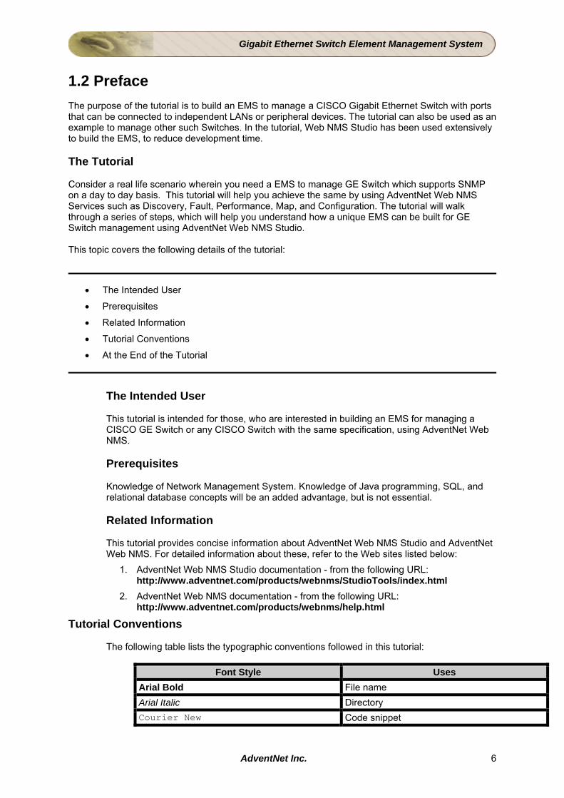
Tutorial Conventions
The following table lists the typographic conventions followed in this tutorial:
Font Style Uses Arial Bold File name Arial Italic Directory Courier New Code snippet
AdventNet Inc. 6

Gigabit Ethernet Switch Element Management System
At the End of the Tutorial From this tutorial you will learn how to
• Build a EMS to manage a CISCO GE Switch by customizing AdventNet Web NMS with the help of AdventNet Web NMS Studio.
• Model the GE Switch and its components.
• Achieve Fault, Configuration, Performance, Map, and Discovery of the Switch and its components.
AdventNet Inc. 7
Gigabit Ethernet Switch Element Management System
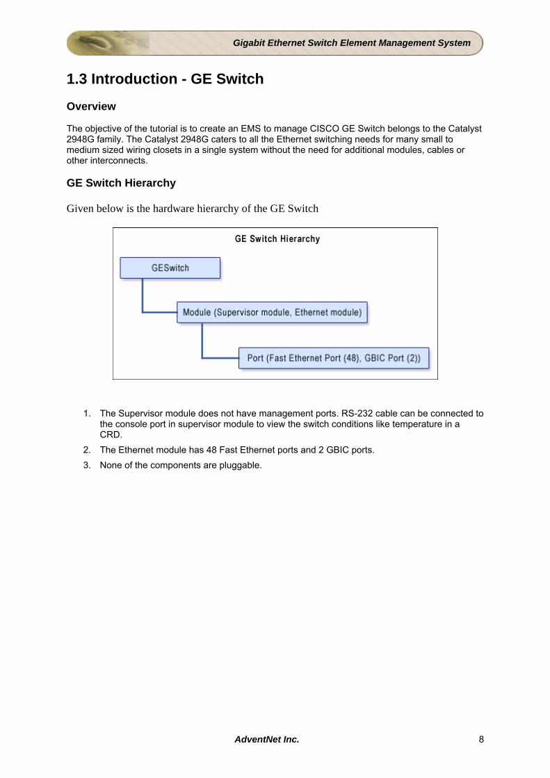
1.3 Introduction - GE Switch Overview The objective of the tutorial is to create an EMS to manage CISCO GE Switch belongs to the Catalyst 2948G family. The Catalyst 2948G caters to all the Ethernet switching needs for many small to medium sized wiring closets in a single system without the need for additional modules, cables or other interconnects. GE Switch Hierarchy Given below is the hardware hierarchy of the GE Switch
1. The Supervisor module does not have management ports. RS-232 cable can be connected to the console port in supervisor module to view the switch conditions like temperature in a CRD.
2. The Ethernet module has 48 Fast Ethernet ports and 2 GBIC ports. 3. None of the components are pluggable.
AdventNet Inc. 8
Gigabit Ethernet Switch Element Management System
1.4 Application Overview In this section, an overview of the Tutorial Application is provided. The tutorial application provides information on how to build an EMS to manage a GE Switch. The tutorial application is built exploring the various modules of AdventNet Web NMS.
• Application Specification
• Implementation in a Nutshell
Application Specification Name of the Application EMS for GE Switch Management
Version of Web NMS Used Web NMS Release 4.7.0 Compatibility with other Versions Not compatible with previous versions of Web NMS
Tools used and their versions AdventNet Web NMS Studio 4.7.0, Configuration Wizard
Platform Specific Requirements No special requirements
Implementation in a Nutshell The tutorial application covers various aspects of network management. Various modules of AdventNet Web NMS are used to achieve the network management objectives as listed below:
• Modeling the GE Switch and its components - Module and Port
• Discovering the GE Switch
• Representing the GE Switch in Web NMS Map
• Managing Alerts of GE Switch and it's Components
• Configuring the GE Switch
• Rebranding AdventNet Web NMS as Your EMS
Modeling the GE Switch and its Component Objects
In AdventNet Web NMS, the managed device data are stored in the database for persistency. For storing the managed devices data into a database, it is necessary to model the managed device and its components. The tutorial explains how to model the GE Switch as managed objects. In order to simulate a real time GE Switch, the related components such as Module and Port are also modeled. The Object Modeling topic, illustrates how the existing AdventNet Web NMS Managed Object model is extended to emulate a real SNMP GE Switch device and its sub-components.
AdventNet Inc. 9
Gigabit Ethernet Switch Element Management System
Discovering GE Switch and its Component Objects
The Discovery process of AdventNet Web NMS discovers all the elements available in the managed network. The tutorial explains how the Discovery process is customized to filter out the node of type GESwitch. The discovered nodes are modeled as explained above and stored in the topology database for effective management. The Discovery topic illustrates how to customize discovery and store the discovered information in the Topology database.
Customizing Maps to Display the GE Switch and its Component Objects
AdventNet Web NMS provides default maps to display various networks and element groups. The tutorial explains how the custom maps are created using Map Filter of Studio. The various components of the GE Switch such as Module and Port are shown in the Map view.
Managing Alerts of GE Switch and its Component Objects
AdventNet Web NMS implements Fault Management to identify failures in the managed network elements. The tutorial explains how to customize the Fault management for Trap handling.
Configuring the GE Switch and its Component Objects
AdventNet provides the Configuration Wizard to build configuration screens to configure devices. The tutorial provides an example on how to create, Configuration screens and the procedure to integrate with Web NMS. Rebranding AdventNet Web NMS as Your EMS
The tutorial rebrands AdventNet Web NMS. The logo, images, etc. can be replaced as you desire using Rebranding Tool in Studio. The I18N Editor for internationalization of various UI references of AdventNet and Web NMS can also be used. With these the EMS developed can easily be rebranded.
AdventNet Inc. 10
Gigabit Ethernet Switch Element Management System
2 Try it Yourself In this section, the steps to deploy the ready built application are provided. This would help you run the application by yourself and view the results. The steps involved are
• Before You Begin
• Get the Application's NAR File
• Deploy the NAR in AdventNet Web NMS
• Start NMS
• View the Result
Before You Begin
• Download the latest version of AdventNet Web NMS. • Get it installed in your machine.
Refer to Installation Guide of AdventNet Web NMS for more details on
• System Requirements
• Startup Options
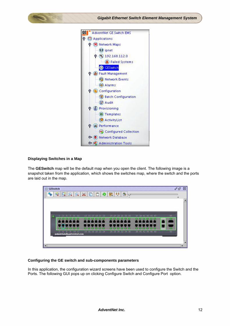
Get the Ready Built application The working example comes bundled with AdventNet Web NMS, as a NAR file. The NAR is actually the ready-built application. Another alternative is to download the latest version of the GES Tutorial from the web site and use the NAR in it. Deploy the Application in AdventNet Web NMS Carry out the instructions given in the Installing the Application section to deploy the NAR file. Start NMS Start the Web NMS Launcher, by invoking WebNMSLauncher.bat/sh file in the <Web NMS HOME> directory. Double-click Start Web NMS Server icon in the Web NMS Launcher. View the Result Connect a Application client to the Web NMS Server in port 9090 as follows: Double-click Application Client icon from the Web NMS Launcher Log in with user as root and password as public. In the left side frame, you will see the map tree. In that you can see that the name of the tree is changed to AdventNet GE Switch EMS. There is a separate node in the Network Maps called GESwitch, which displays the switches map.
AdventNet Inc. 11
Gigabit Ethernet Switch Element Management System
Displaying Switches in a Map The GESwitch map will be the default map when you open the client. The following image is a snapshot taken from the application, which shows the switches map, where the switch and the ports are laid out in the map.
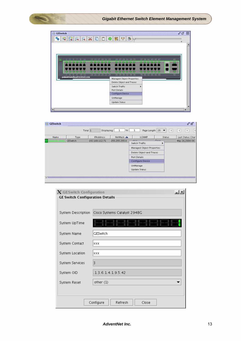
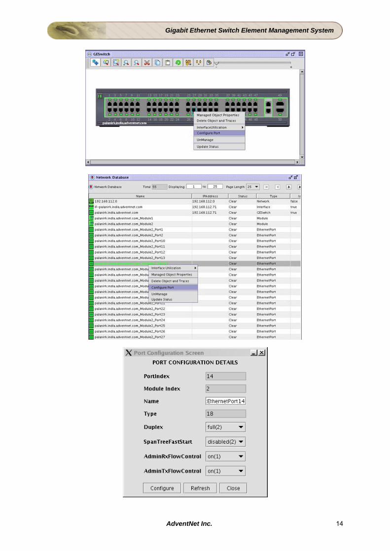
Configuring the GE switch and sub-components parameters In this application, the configuration wizard screens have been used to configure the Switch and the Ports. The following GUI pops up on clicking Configure Switch and Configure Port option.
AdventNet Inc. 12
Gigabit Ethernet Switch Element Management System
AdventNet Inc. 13
Gigabit Ethernet Switch Element Management System
AdventNet Inc. 14

Gigabit Ethernet Switch Element Management System
3 Design Phase An Introduction This document provides you an overall picture of the Design Phase in building an EMS to manage a GESwitch Application Design: The document provides an overview of the applications that have to built to develop an EMS to manage a GESwitch. Modeling the Managed Resource: The document provides an insight into the concept of object modeling in Web NMS, and the methodology adopted in the Tutorial for modeling the GE Switch Detailed Resource Modeling: The document provides details about the GE Switch, its components and the properties to be managed.
AdventNet Inc. 15
Gigabit Ethernet Switch Element Management System
3.1 Application Design AdventNet Web NMS Studio is equipped with a rich suite of tools to support the entire development cycle of an EMS from modeling your network elements as objects to service customization, packaging, and in the end installing it in Web NMS. This significantly reduces the time taken to build an EMS. Aim To come up with the design on customizing the AdventNet Web NMS platform features to provide various functions to the EMS, as specified in the requirements. EMS Management Requirements
• Modeling the GE Switch and its components as Managed Resource • Discovering the GE Switch in the network • Representing the GE Switch and Its components in the Map • Fault Management of the GE Switch • Configuring the GE Switch • Performance Management through periodic Data Collection • Rebranding of the EMS
Managed Resource Modeling
Objective
Modeling a device enables you to represent the various attributes and the behavior of the corresponding physical device and its components in a convenient way so as to reflect their current state at any time. The EMS stores these persistent data in the database. In the Tutorial, the properties of the discovered MO object are matched with the properties of the GESwitch, and the discovered MO is modeled as GESwitch and added to the topology database. The sub components, Module, and Port are also modeled, after querying the device.
Tasks
Define the resources to be managed by the EMS. The properties of the GE Switch and its components - Module and Port that are to be used for modeling are given below:
Managed Resource Name Attributes in Managed Resource
GE Switch sysObjectId, sysDescr, sysContact, sysName, sysServices, ifNumber, sysMgmtType
Module moduleIndex, moduleType moduleName, moduleNumPorts, moduleModel, moduleHWVersion, moduleFWVersion, moduleSWVersion, moduleSerialNumberString
Port portModuleIndex, portIndex, portName, portType, portIfIndex, snmpport, portAgent
The Role of Studio
Using the Resource Factory of the Studio, all the above resources can be modeled easily.
AdventNet Inc. 16
Gigabit Ethernet Switch Element Management System
Discovering GE Switch
Objective
To automatically discover and add the GE Switch device and its components into the topology database of Web NMS. This will enable identifying the component hierarchy of the GE Switch. In the Tutorial, the GESwitch is discovered, based on the matching criteria defined in the filter. The sub components are also discovered, based on the information queried from the agent.
Tasks
Create a Custom Discovery Filter defining the containment hierarchy of the device and its components.
The Role of Studio
The Custom Discovery Filter Wizard will help you define the discovery filter. During discovery, Web NMS will discover the device and its components and store them in the database according to the containment hierarchy that has been defined in the discovery filter.
Representing the GE Switch and Its Components in the Map
Objective
To graphically represent the GE Switch and its components, illustrating the containment hierarchy, in the map view of Web NMS Client. In the Tutorial, all the objects added by the discovery filter is passed to the Map Filter, and the corresponding map symbols are created for the objects and then added to the map designed for the GESwitch.
Tasks
• Create a custom map for the GE Switch and its components
The Role of Studio
Using the Map Filter Wizard the above tasks can be completed. Fault Management of the GE Switch
Objective
To monitor and manage the failures in the system effectively including, polling the GE Switch and its components periodically for their status and thereby take preventive action where necessary.
Tasks
• Convert the failure notifications (Traps) into meaningful Events. • Parse the trap generated for the above OID's into meaningful events
The Role of Studio
Using the Trap Filter Wizard of the Studio, create a Trap Filter that filters the traps and converts them into meaningful Events which can be managed. Edit the trap.parsers file to parse the events generated from the Trap Filter
AdventNet Inc. 17

Gigabit Ethernet Switch Element Management System
Configuring the GE Switch
Objective To configure the GESwitch and the Ports at runtime from the Web NMS Client.
Tasks Create two screens GESwitch Configuration and GEPort Configuration for configuring the switch and port respectively. The Configure Device menu should invoke the Switch configuration screen, and on right clicking the Ports in the Switch, the Port Details screen should pop up.
The Role of Studio
The Configuration Wizard present in Client Builder can be used to create the screens as mentioned above.
Performance Management
Objective To monitor the GESwitch and the Ports in the Switch. In the tutorial, Tasks Modify the polling.conf to monitor the data collected periodically by the Switch. Write a Poll filter to collect the InOctets, and OutOctets for the Ports. Create menus in the Web NMS Client, for monitoring the Switch and the Ports
The Role of Studio
Edit the polling.conf using the XML Editor, and write a Poll Filter using Studio's Poll Filter Wizard.
Rebranding the EMS
Objective
The EMS has to be renamed according to your requirements. All the relevant images and icons will have be changed to reflect its new name .
Tasks
• Replace the existing AdventNet and Web NMS images and logo to GE Switch. Rebrand the text and buttons that appear in the client of the EMS.
The Role of Studio
Using the Rebranding tool, the EnglishToNative.properties file will be changed to internationalize the text that appears in the client and the images and logo of AdventNet will also be replaced with that of GE Switch.
AdventNet Inc. 18

Gigabit Ethernet Switch Element Management System
3.2 Modeling the Managed Resources This topic concentrates on various aspects involved in the design of Managed Object. The various aspects covered are as listed below:
• What Are the Different Methods Available to Design Managed Resources?
• How Is Web Core Object Resource Is Modeled?
• An Example Modeling of Object Resources for This Application
• Class Diagram of Managed Resources of EMS application
• Naming Convention Used in Modeling the Managed Resources
What Are the Different Methods Available to Design Managed Resources? We have two choices for our design of managed elements.
• Using the dynamic properties of Web NMS Managed Objects.
• Extending the existing Managed Objects. The former is a quick solution requiring less design effort but a cumbersome design. The later is a cleaner design. The second choice will serve our application needs better, because it provides a neat design. This approach also results in a better table structure for storing our objects in an RDBMS. Hence, the second approach is adopted in this tutorial. How Is Web Core Object Resource Is Modeled? The core Object model of AdventNet Web NMS is simple and easy to learn and extend for each application. The elements of the core model are designed for IP networks and are sufficient to represent common IP networks. However, for most specific applications, e.g., the management of a cable modem system, the model will be extended. The topology database has the following base elements: ManagedObject The base class of all objects in the Topology database. TopoObject The base class of all IP objects in the Topology database. Network This object represents an IP network. Node This object represents an IP network node. SNMP Node This object represents an IP network node with an SNMP Agent. IP Address This object represents an IP interface. SNMP Interface This object represents an IP interface with an SNMP Agent in its parent node. An Example Modeling of Object Resources for This Application GESwitch This represents a GE Switch that is initially discovered via SNMP, i.e., Web NMS finds it
as an SNMP Node in the network. Module Each device consists of 2 modules - Supervisor Module and Ethernet Module which and
are numbered 0-2. Port The Ethernet module has 48 FastEthernet ports and 2 GBIC ports. The Supervisor
module does not have any ports.
AdventNet Inc. 19
Gigabit Ethernet Switch Element Management System
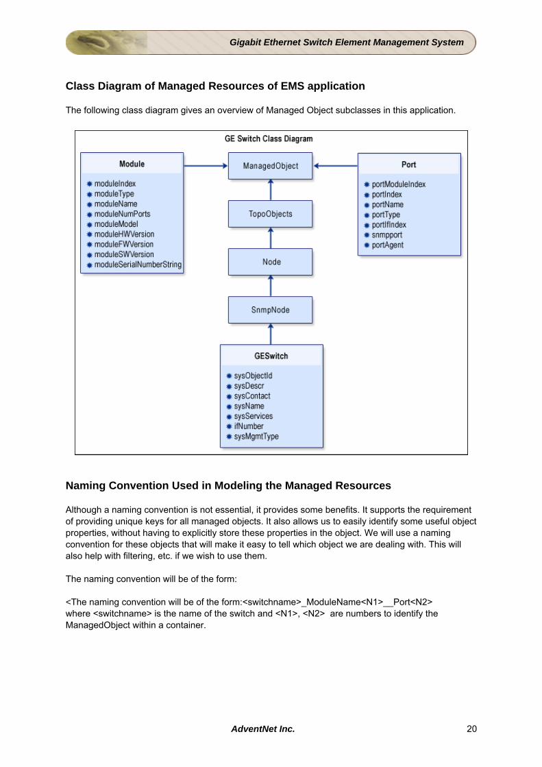
Class Diagram of Managed Resources of EMS application The following class diagram gives an overview of Managed Object subclasses in this application.
Naming Convention Used in Modeling the Managed Resources Although a naming convention is not essential, it provides some benefits. It supports the requirement of providing unique keys for all managed objects. It also allows us to easily identify some useful object properties, without having to explicitly store these properties in the object. We will use a naming convention for these objects that will make it easy to tell which object we are dealing with. This will also help with filtering, etc. if we wish to use them. The naming convention will be of the form: <The naming convention will be of the form:<switchname>_ModuleName<N1>__Port<N2> where <switchname> is the name of the switch and <N1>, <N2> are numbers to identify the ManagedObject within a container.
AdventNet Inc. 20
Gigabit Ethernet Switch Element Management System
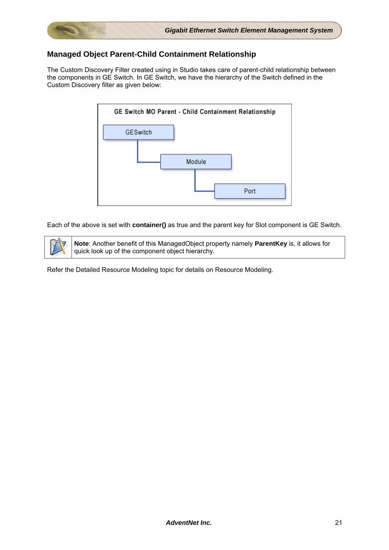
Managed Object Parent-Child Containment Relationship The Custom Discovery Filter created using in Studio takes care of parent-child relationship between the components in GE Switch. In GE Switch, we have the hierarchy of the Switch defined in the Custom Discovery filter as given below:
Each of the above is set with container() as true and the parent key for Slot component is GE Switch.
Note: Another benefit of this ManagedObject property namely ParentKey is, it allows for quick look up of the component object hierarchy.
Refer the Detailed Resource Modeling topic for details on Resource Modeling.
AdventNet Inc. 21
Gigabit Ethernet Switch Element Management System
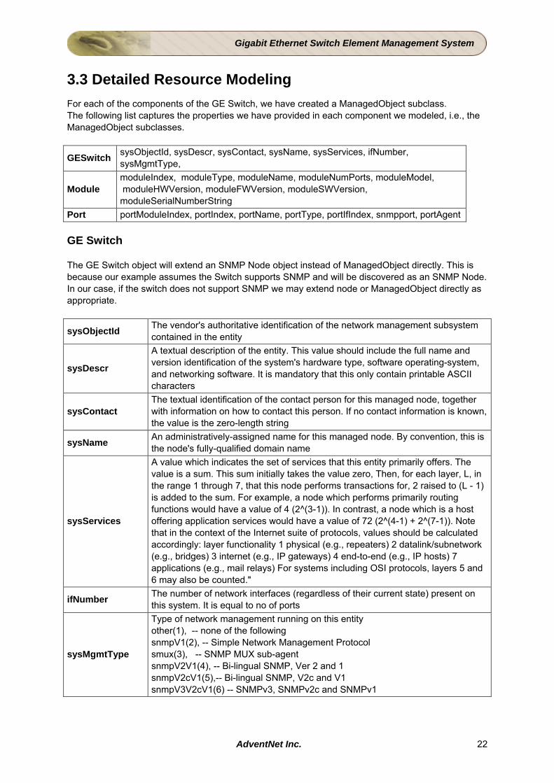
3.3 Detailed Resource Modeling For each of the components of the GE Switch, we have created a ManagedObject subclass. The following list captures the properties we have provided in each component we modeled, i.e., the ManagedObject subclasses.
GESwitch sysObjectId, sysDescr, sysContact, sysName, sysServices, ifNumber, sysMgmtType,
Module moduleIndex, moduleType, moduleName, moduleNumPorts, moduleModel, moduleHWVersion, moduleFWVersion, moduleSWVersion, moduleSerialNumberString
Port portModuleIndex, portIndex, portName, portType, portIfIndex, snmpport, portAgent GE Switch The GE Switch object will extend an SNMP Node object instead of ManagedObject directly. This is because our example assumes the Switch supports SNMP and will be discovered as an SNMP Node. In our case, if the switch does not support SNMP we may extend node or ManagedObject directly as appropriate.
sysObjectId The vendor's authoritative identification of the network management subsystem contained in the entity
sysDescr
A textual description of the entity. This value should include the full name and version identification of the system's hardware type, software operating-system, and networking software. It is mandatory that this only contain printable ASCII characters
sysContact The textual identification of the contact person for this managed node, together with information on how to contact this person. If no contact information is known, the value is the zero-length string
sysName An administratively-assigned name for this managed node. By convention, this is the node's fully-qualified domain name
sysServices
A value which indicates the set of services that this entity primarily offers. The value is a sum. This sum initially takes the value zero, Then, for each layer, L, in the range 1 through 7, that this node performs transactions for, 2 raised to (L - 1) is added to the sum. For example, a node which performs primarily routing functions would have a value of 4 (2^(3-1)). In contrast, a node which is a host offering application services would have a value of 72 (2^(4-1) + 2^(7-1)). Note that in the context of the Internet suite of protocols, values should be calculated accordingly: layer functionality 1 physical (e.g., repeaters) 2 datalink/subnetwork (e.g., bridges) 3 internet (e.g., IP gateways) 4 end-to-end (e.g., IP hosts) 7 applications (e.g., mail relays) For systems including OSI protocols, layers 5 and 6 may also be counted."
ifNumber The number of network interfaces (regardless of their current state) present on this system. It is equal to no of ports
sysMgmtType
Type of network management running on this entity other(1), -- none of the following snmpV1(2), -- Simple Network Management Protocol smux(3), -- SNMP MUX sub-agent snmpV2V1(4), -- Bi-lingual SNMP, Ver 2 and 1 snmpV2cV1(5),-- Bi-lingual SNMP, V2c and V1 snmpV3V2cV1(6) -- SNMPv3, SNMPv2c and SNMPv1
AdventNet Inc. 22
Gigabit Ethernet Switch Element Management System
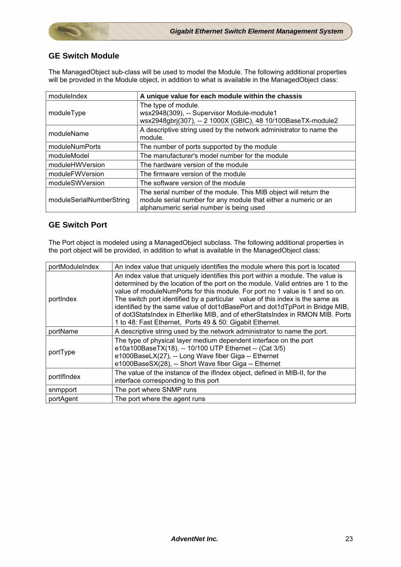
GE Switch Module The ManagedObject sub-class will be used to model the Module. The following additional properties will be provided in the Module object, in addition to what is available in the ManagedObject class: moduleIndex A unique value for each module within the chassis
moduleType The type of module. wsx2948(309), -- Supervisor Module-module1 wsx2948gbrj(307), -- 2 1000X (GBIC), 48 10/100BaseTX-module2
moduleName A descriptive string used by the network administrator to name the module.
moduleNumPorts The number of ports supported by the module moduleModel The manufacturer's model number for the module moduleHWVersion The hardware version of the module moduleFWVersion The firmware version of the module moduleSWVersion The software version of the module
moduleSerialNumberString The serial number of the module. This MIB object will return the module serial number for any module that either a numeric or an alphanumeric serial number is being used
GE Switch Port The Port object is modeled using a ManagedObject subclass. The following additional properties in the port object will be provided, in addition to what is available in the ManagedObject class: portModuleIndex An index value that uniquely identifies the module where this port is located
portIndex
An index value that uniquely identifies this port within a module. The value is determined by the location of the port on the module. Valid entries are 1 to the value of moduleNumPorts for this module. For port no 1 value is 1 and so on. The switch port identified by a particular value of this index is the same as identified by the same value of dot1dBasePort and dot1dTpPort in Bridge MIB, of dot3StatsIndex in Etherlike MIB, and of etherStatsIndex in RMON MIB. Ports 1 to 48: Fast Ethernet, Ports 49 & 50: Gigabit Ethernet.
portName A descriptive string used by the network administrator to name the port.
portType
The type of physical layer medium dependent interface on the port e10a100BaseTX(18), -- 10/100 UTP Ethernet -- (Cat 3/5) e1000BaseLX(27), -- Long Wave fiber Giga -- Ethernet e1000BaseSX(28), -- Short Wave fiber Giga -- Ethernet
portIfIndex The value of the instance of the ifIndex object, defined in MIB-II, for the interface corresponding to this port
snmpport The port where SNMP runs portAgent The port where the agent runs
AdventNet Inc. 23

Gigabit Ethernet Switch Element Management System
4 Implementation Phase - Introduction This document provides an outline of the various steps in the GES EMS Implementation phase.
1. Creating a GES EMS Project 2. Modeling the GE Switch and its Components 3. Discovering the GE Switch 4. Creating Maps to Display GE Switch Devices 5. Performance Monitoring of the GE Switch 6. Fault Management 7. Building Configuration Screens 8. Rebranding 9. Packaging GES EMS Project
AdventNet Inc. 24

Gigabit Ethernet Switch Element Management System
4.1 Creating a GES EMS Project The first step toward any customization with the AdventNet Web NMS Studio is to create a Project. The project stores all the information that are essential for customizing the application. Follow the steps given below to create the project. Refer to Creating Project topic for how to create a project. Instructions
Step 1: Starting Studio Tool and Invoking Project Wizard 1. Invoke the Web NMS Launcher using the WebNMSLauncher.bat/sh under <Web
NMS Home>. 2. Double-click Web NMS IDE icon and double-click Studio to invoke Web NMS Studio. 3. Select File -> New Project menu item to invoke the Project Wizard.
Step 2: Project Details
In the "Project Details" of the wizard, provide the following details: 1. Provide the Project Name as "GES_Tutorial". 2. Provide the Package Name as "com.adventnet.ges". 3. Retain the Application Name as "GES_Tutorial". You can change the Application
Name. 4. Retain the Version as "1.0". 5. Provide the location of Web NMS in Web NMS Home. 6. Click Next to proceed to next screen.
Step 3: Device Details
In the "Device Details" of the wizard, provide the following details about the Device. 1. Ensure the value "SNMP" is selected in Protocol combo box. 2. Enter the Device Type field with the value "CISCO GES". 3. Provide the Device OID as .1.3.6.1.4.1.9.5.42. As the Device is not listed in the
OIDType.data file, the Device name and its OID have to be provided manually. The values will be added to the OIDType.data file after completion of the Project creation.
4. Click Browse to select the following MIB's CISCO-STACK-MIB RMON-MIB RFC-1213-MIB
5. Click Next to proceed to the next screen.
Step 4: Web NMS Services Details
In the "Service Details" screen, ensure the following services are checked and uncheck the other services that are not listed below. All Services are selected by default.
• MANAGEDRESOURCE
• DISCOVERY
• MAP
• FAULT
• CONFIGURATION
AdventNet Inc. 25

Gigabit Ethernet Switch Element Management System
• PERFORMANCE
• SECURITY
• REBRANDING Click Next to proceed to the next screen.
Step 5: Database Details
In the "RDBMS Details" screen, ensure your choice of Databases is selected from the listed Databases by checking the check boxes. The Databases required for the GES EMS Project are
• MySQL
• Oracle Click Next to proceed to next screen.
Step 6: User Details and Summary
In the "User Details" screen, select the Single User radio button, because the project is built by single user. Click Next to proceed to next screen. You can view the GES_Tutorial Project details you had provided in the wizard. Click Finish to create the Project workspace.
This completes the creation of Project Workspace.
AdventNet Inc. 26
Gigabit Ethernet Switch Element Management System
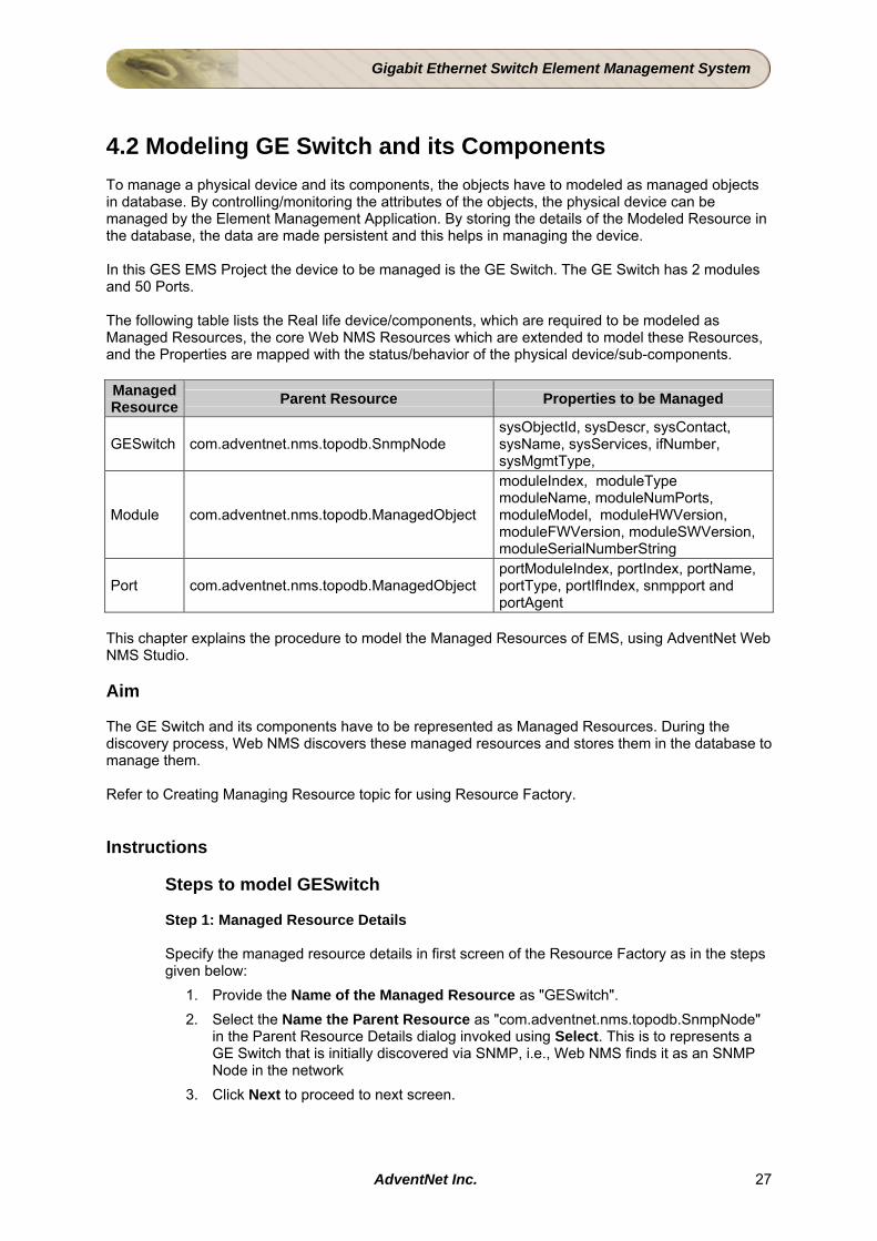
4.2 Modeling GE Switch and its Components To manage a physical device and its components, the objects have to modeled as managed objects in database. By controlling/monitoring the attributes of the objects, the physical device can be managed by the Element Management Application. By storing the details of the Modeled Resource in the database, the data are made persistent and this helps in managing the device. In this GES EMS Project the device to be managed is the GE Switch. The GE Switch has 2 modules and 50 Ports. The following table lists the Real life device/components, which are required to be modeled as Managed Resources, the core Web NMS Resources which are extended to model these Resources, and the Properties are mapped with the status/behavior of the physical device/sub-components. Managed Resource Parent Resource Properties to be Managed
GESwitch com.adventnet.nms.topodb.SnmpNode sysObjectId, sysDescr, sysContact, sysName, sysServices, ifNumber, sysMgmtType,
Module com.adventnet.nms.topodb.ManagedObject
moduleIndex, moduleType moduleName, moduleNumPorts, moduleModel, moduleHWVersion, moduleFWVersion, moduleSWVersion, moduleSerialNumberString
Port com.adventnet.nms.topodb.ManagedObject portModuleIndex, portIndex, portName, portType, portIfIndex, snmpport and portAgent
This chapter explains the procedure to model the Managed Resources of EMS, using AdventNet Web NMS Studio. Aim The GE Switch and its components have to be represented as Managed Resources. During the discovery process, Web NMS discovers these managed resources and stores them in the database to manage them. Refer to Creating Managing Resource topic for using Resource Factory. Instructions
Steps to model GESwitch
Step 1: Managed Resource Details
Specify the managed resource details in first screen of the Resource Factory as in the steps given below:
1. Provide the Name of the Managed Resource as "GESwitch". 2. Select the Name the Parent Resource as "com.adventnet.nms.topodb.SnmpNode"
in the Parent Resource Details dialog invoked using Select. This is to represents a GE Switch that is initially discovered via SNMP, i.e., Web NMS finds it as an SNMP Node in the network
3. Click Next to proceed to next screen.
AdventNet Inc. 27
Gigabit Ethernet Switch Element Management System
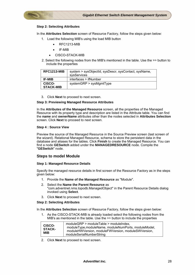
Step 2: Selecting Attributes
In the Attributes Selection screen of Resource Factory, follow the steps given below:
1. Load the following MIB's using the load MIB button • RFC1213-MIB • IF-MIB
• CISCO-STACK-MIB 2. Select the following nodes from the MIB's mentioned in the table. Use the >> button to include the properties
RFC1213-MIB system > sysObjectId, sysDescr, sysContact, sysName, sysServices
IF-MIB interfaces > ifNumber CISCO-STACK-MIB
systemGRP > sysMgmtType
3. Click Next to proceed to next screen.
Step 3: Previewing Managed Resource Attributes
In the Attributes of the Managed Resource screen, all the properties of the Managed Resource with its property type and description are listed in the Attribute table. You can find the name and ownerName attributes other than the nodes selected in Attributes Selection screen. Click Next to proceed to next screen.
Step 4 : Source View
Preview the source of the Managed Resource in the Source Preview screen (last screen of the wizard). Relational Managed Resource, schema to store the persistent data in the database and aliases for the tables. Click Finish to create the Managed Resource. You can find a node GESwitch added under the MANAGEDRESOURCE node. Compile the "GESwitch" node.
Steps to model Module
Step 1: Managed Resource Details
Specify the managed resource details in first screen of the Resource Factory as in the steps given below:
1. Provide the Name of the Managed Resource as "Module". 2. Select the Name the Parent Resource as
"com.adventnet.nms.topodb.ManagedObject" in the Parent Resource Details dialog invoked using Select.
3. Click Next to proceed to next screen. Step 2: Selecting Attributes
In the Attributes Selection screen of Resource Factory, follow the steps given below:
1. As the CISCO-STACK-MIB is already loaded select the following nodes from the MIB's as mentioned in the table. Use the >> button to include the properties
CISCO-STACK-MIB
moduleGRP > moduleTable > moduleIndex, moduleType,moduleName, moduleNumPorts, moduleModel, moduleHWVersion, moduleFWVersion, moduleSWVersion, moduleSerialNumberString
2. Click Next to proceed to next screen.
AdventNet Inc. 28
Gigabit Ethernet Switch Element Management System
Step 3: Previewing Managed Resource Attributes
In the Attributes of the Managed Resource screen, all the properties of the Managed Resource with its property type and description are listed in the Attribute table. You can find the name and ownerName attributes other than the nodes selected in Attributes Selection screen. Click Next to proceed to next screen.
Step 4 : Source View
Preview the source of the Managed Resource in the Source Preview screen (last screen of the wizard). Relational Managed Resource, schema to store the persistent data in the database and aliases for the tables. Click Finish to create the Managed Resource. You can find a node Module added under the MANAGEDRESORCE. Steps to model Port
Step 1: Managed Resource Details
Specify the managed resource details in first screen of the Resource Factory as in the steps given below:
1. Provide the Name of the Managed Resource as "Port". 2. Select the Name the Parent Resource as
"com.adventnet.nms.topodb.ManagedObject" in the Parent Resource Details dialog invoked using Select.
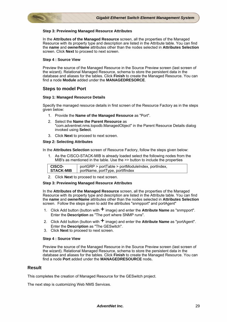
3. Click Next to proceed to next screen. Step 2: Selecting Attributes
In the Attributes Selection screen of Resource Factory, follow the steps given below:
1. As the CISCO-STACK-MIB is already loaded select the following nodes from the MIB's as mentioned in the table. Use the >> button to include the properties
CISCO-STACK-MIB
portGRP > portTable > portModuleIndex, portIndex, portName, portType, portIfIndex
2. Click Next to proceed to next screen. Step 3: Previewing Managed Resource Attributes
In the Attributes of the Managed Resource screen, all the properties of the Managed Resource with its property type and description are listed in the Attribute table. You can find the name and ownerName attributes other than the nodes selected in Attributes Selection screen. Follow the steps given to add the attributes "snmpport" and portAgent"
1. Click Add button (button with + image) and enter the Attribute Name as "snmpport". Enter the Description as "The port where SNMP runs".
2. Click Add button (button with + image) and enter the Attribute Name as "portAgent". Enter the Description as "The GESwitch".
3. Click Next to proceed to next screen. Step 4 : Source View
Preview the source of the Managed Resource in the Source Preview screen (last screen of the wizard). Relational Managed Resource, schema to store the persistent data in the database and aliases for the tables. Click Finish to create the Managed Resource. You can find a node Port added under the MANAGEDRESOURCE node.
Result This completes the creation of Managed Resource for the GESwitch project. The next step is customizing Web NMS Services.
AdventNet Inc. 29
Gigabit Ethernet Switch Element Management System
4.3 Discovering the GE Switch During the discovery process, the NMS discovery engine passes each network element through the discovery filter. The devices that satisfy the filter criteria is added to the database. Using Studio, define a Discovery filter for the resources to be managed. Define either a Custom Discovery Filter, Shallow Discovery filter or Deep Discovery filter to discover the GE Switch in the network For the Tutorial, Custom Discovery Filter has been chosen, as the CISCO-STACK MIB chosen for the tutorial does not reflect the actual GE Switch device. The reasons being:
• Port Table in CISCO-STACK-MIB does not import the values from Module Table. • portType in CISCO-STACK-MIB is identified as a key not as an index.
Aim The GE Switch and its components have to be discovered and added to the topology database. Instructions Steps to create Custom Discovery Filter
Step 1 - Naming the Filter Right click on the Discovery Filter node and choose New. In the dialog that appears choose Custom Discovery Filter. Enter the Custom Discovery Filter name as GESDiscoveryFilter. Click Next. Step 2 - Defining the Device Hierarchy Right-click the Device node and choose Modify. Enter the name as GESwitch. Right-click the GESwitch node and choose Create > CreateSubNode. Enter the name as Module. Right-click the Module node and choose Create > CreateSubNode. Enter the name as Port.
Step 3 - Defining Device Details and associating managed resource to the Device and its components For the Switch hierarchy defined above details of the Switch and its components - Module and Port, have to be populated in the screen. Click on the Device Name and enter the details as provided in the table given below:
Device Name Device Details GESwitch Managed Resource Name : com.adventnet.ges.GESSwitch
Module Is No of Module > 1 - Yes Managed Resource - com.adventnet.ges.Module
Port Is No of Port > 1 - Yes Managed Resource - com.adventnet.ges.Port
Click Next to proceed.
View the Discovery filter, Abstract and Adapter Source
Click Finish to close the Wizard. The following three source are generated.
• GESDiscoveryFilter • AbstractGESDiscoveryFilter • GESDiscoveryFilterAdapter
AdventNet Inc. 30
Gigabit Ethernet Switch Element Management System
Points to Note
1. In The GESDiscoveryFilter.java the device hierarchy as modeled in the UI is encapsulated. The class takes care of instantiating and adding the class to the database.
2. Methods in the GESDiscoveryFilter have to be expanded in the GESDiscoveryFilterAdapter class. The GESDiscoveryFilterAdapter class extends the AbstractGESDiscoveryFilter.java class and permits users to plug in his/her own implementation for device contact queries (such as getting index information, filling the properties for the instantiated Managed Resource).
3. From Step 4 directions are provided on how to implement the method call in the GESDiscoveryFilter class in the GESDiscoveryFilterAdapter class.
4. The Property Source tab can be used to add Properties for the Device and its components in the GESDiscoveryFilterAdapter class. Step 1: Place the cursor in the area where you intend to add code. Step 2 : Click on the Property Source Tab located above the Source code editor. In the dialog that pops up first choose the Managed Resource from the combo box for which you want to set properties. Step 3 : The Property editor displays the list of properties for the chosen managed resource. Click the property name row. For more details read the section Property Editor. Click Next. The code generated for the managed resource is displayed. Click Insert to add the code in the areas where the cursor was placed prior to clicking the Property source tab or use the Copy button and paste the code in the required area.
Step 4 - Populating the Device and it's Sub Components with the Respective Properties:
Object : GESwitch
Method in Discovery Filter class :
discoveredMO=impl.getGESwitch(mObj,tApi);
In the above method the following method call has to be implemented in the Adapter class
(1) public ManagedObject getGESwitch()
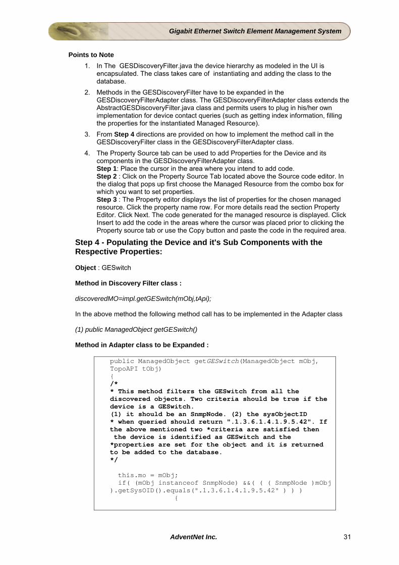
Method in Adapter class to be Expanded :
public ManagedObject getGESwitch(ManagedObject mObj, TopoAPI tObj) { /* * This method filters the GESwitch from all the discovered objects. Two criteria should be true if the device is a GESwitch. (1) it should be an SnmpNode. (2) the sysObjectID * when queried should return ".1.3.6.1.4.1.9.5.42". If the above mentioned two *criteria are satisfied then the device is identified as GESwitch and the *properties are set for the object and it is returned to be added to the database. */ this.mo = mObj; if( (mObj instanceof SnmpNode) &&( ( ( SnmpNode )mObj ).getSysOID().equals(".1.3.6.1.4.1.9.5.42" ) ) ) {
AdventNet Inc. 31
Gigabit Ethernet Switch Element Management System
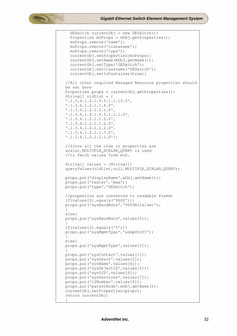
GESwitch currentObj = new GESwitch(); Properties moProps = mObj.getProperties(); moProps.remove("name"); moProps.remove("classname"); moProps.remove("type"); currentObj.setProperties(moProps); currentObj.setName(mObj.getName()); currentObj.setType("GESwitch"); currentObj.setClassname("GESwitch"); currentObj.setIsContainer(true); //All other required Managed Resource properties should be set here Properties props = currentObj.getProperties(); String[] oidList = { ".1.3.6.1.4.1.9.5.1.1.10.0", ".1.3.6.1.2.1.1.4.0", ".1.3.6.1.2.1.1.1.0", ".1.3.6.1.4.1.9.5.1.1.1.0", ".1.3.6.1.2.1.1.5.0", ".1.3.6.1.2.1.1.2.0", ".1.3.6.1.2.1.1.2.0", ".1.3.6.1.2.1.1.7.0", ".1.3.6.1.2.1.2.1.0"}; //Since all the oids or properties are scalar,MULTIPLE_SCALAR_QUERY is used //to fetch values from mib. String[] values = (String[]) queryValues(oidList,null,MULTIPLE_SCALAR_QUERY); props.put("displayName",mObj.getName()); props.put("tester","max"); props.put("type","GESwitch"); //properties are converted to readable format if(values[0].equals("9600")){ props.put("sysBaudRate","9600Bits/sec"); } else{ props.put("sysBaudRate",values[0]); } if(values[3].equals("5")){ props.put("sysMgmtType","snmpV2cV1"); } else{ props.put("sysMgmtType",values[3]); } props.put("sysContact",values[1]); props.put("sysDescr",values[2]); props.put("sysName",values[4]); props.put("sysObjectID",values[5]); props.put("sysOID",values[6]); props.put("sysServices",values[7]); props.put("ifNumber",values[8]); props.put("parentNode",mObj.getName()); currentObj.setProperties(props); return currentObj; }
AdventNet Inc. 32
Gigabit Ethernet Switch Element Management System
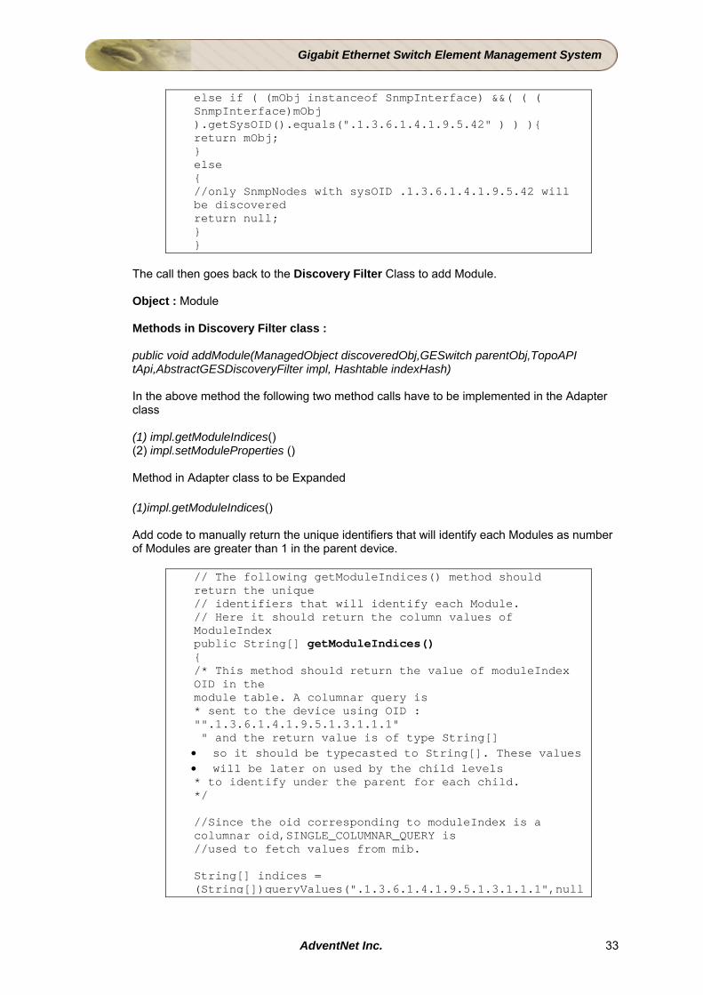
else if ( (mObj instanceof SnmpInterface) &&( ( ( SnmpInterface)mObj ).getSysOID().equals(".1.3.6.1.4.1.9.5.42" ) ) ){ return mObj; } else { //only SnmpNodes with sysOID .1.3.6.1.4.1.9.5.42 will be discovered return null; } }
The call then goes back to the Discovery Filter Class to add Module.
Object : Module Methods in Discovery Filter class : public void addModule(ManagedObject discoveredObj,GESwitch parentObj,TopoAPI tApi,AbstractGESDiscoveryFilter impl, Hashtable indexHash) In the above method the following two method calls have to be implemented in the Adapter class (1) impl.getModuleIndices() (2) impl.setModuleProperties ()
Method in Adapter class to be Expanded
(1)impl.getModuleIndices()
Add code to manually return the unique identifiers that will identify each Modules as number of Modules are greater than 1 in the parent device.
// The following getModuleIndices() method should return the unique // identifiers that will identify each Module. // Here it should return the column values of ModuleIndex public String[] getModuleIndices() { /* This method should return the value of moduleIndex OID in the module table. A columnar query is * sent to the device using OID : "".1.3.6.1.4.1.9.5.1.3.1.1.1" " and the return value is of type String[] • so it should be typecasted to String[]. These values • will be later on used by the child levels * to identify under the parent for each child. */ //Since the oid corresponding to moduleIndex is a columnar oid,SINGLE_COLUMNAR_QUERY is //used to fetch values from mib. String[] indices = (String[])queryValues(".1.3.6.1.4.1.9.5.1.3.1.1.1",null
AdventNet Inc. 33
Gigabit Ethernet Switch Element Management System
, SINGLE_COLUMNAR_QUERY); return indices; }
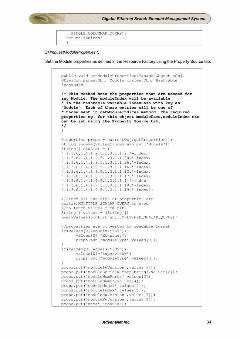
2) impl.setModuleProperties ()
Set the Module properties as defined in the Resource Factory using the Property Source tab.
public void setModuleProperties(ManagedObject mObj, GESwitch parentObj, Module currentObj, Hashtable indexHash) /* This method sets the properties that are needed for any Module. The moduleIndex will be available * in the hashtable variable indexHash with key as "Module". Each of these entries will be one of * those sent in getModuleIndices method. The required properties eg. for this object moduleName,moduleIndex etc can be set using the Property Source tab. */ { Properties props = currentObj.getProperties(); String index=(String)indexHash.get("Module"); String[] oidList = { ".1.3.6.1.4.1.9.5.1.3.1.1.2."+index, ".1.3.6.1.4.1.9.5.1.3.1.1.20."+index, ".1.3.6.1.4.1.9.5.1.3.1.1.26."+index, ".1.3.6.1.4.1.9.5.1.3.1.1.14."+index, ".1.3.6.1.4.1.9.5.1.3.1.1.13."+index, ".1.3.6.1.4.1.9.5.1.3.1.1.17."+index, ".1.3.6.1.4.1.9.5.1.3.1.1.1."+index, ".1.3.6.1.4.1.9.5.1.3.1.1.18."+index, ".1.3.6.1.4.1.9.5.1.3.1.1.19."+index}; //Since all the oids or properties are scalar,MULTIPLE_SCALAR_QUERY is used //to fetch values from mib. String[] values = (String[]) queryValues(oidList,null,MULTIPLE_SCALAR_QUERY); //properties are converted to readable format if(values[0].equals("307")){ values[0]="Ethernet"; props.put("moduleType",values[0]); } if(values[0].equals("309")){ values[0]="Supervisor"; props.put("moduleType",values[0]); } props.put("moduleSwVersion",values[1]); props.put("moduleSerialNumberString",values[2]); props.put("moduleNumPorts",values[3]); props.put("moduleName",values[4]); props.put("moduleModel",values[5]); props.put("moduleIndex",values[6]); props.put("moduleHwVersion",values[7]); props.put("moduleFwVersion",values[8]); props.put("name","Module");
AdventNet Inc. 34
Gigabit Ethernet Switch Element Management System
props.put("type","Module"); props.put("pollInterval","300"); props.put("tester","usertester"); System.out.println("Properties "+props); currentObj.setProperties(props); }
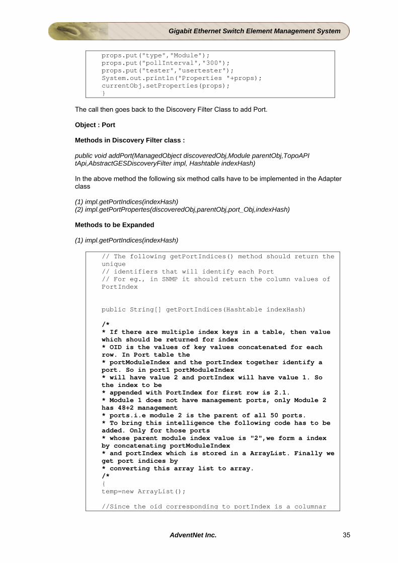
The call then goes back to the Discovery Filter Class to add Port. Object : Port Methods in Discovery Filter class : public void addPort(ManagedObject discoveredObj,Module parentObj,TopoAPI tApi,AbstractGESDiscoveryFilter impl, Hashtable indexHash) In the above method the following six method calls have to be implemented in the Adapter class (1) impl.getPortIndices(indexHash) (2) impl.getPortPropertes(discoveredObj,parentObj,port_Obj,indexHash) Methods to be Expanded
(1) impl.getPortIndices(indexHash)
// The following getPortIndices() method should return the unique // identifiers that will identify each Port // For eg., in SNMP it should return the column values of PortIndex public String[] getPortIndices(Hashtable indexHash) /* * If there are multiple index keys in a table, then value which should be returned for index * OID is the values of key values concatenated for each row. In Port table the * portModuleIndex and the portIndex together identify a port. So in port1 portModuleIndex * will have value 2 and portIndex will have value 1. So the index to be * appended with PortIndex for first row is 2.1. * Module 1 does not have management ports, only Module 2 has 48+2 management * ports.i.e module 2 is the parent of all 50 ports. * To bring this intelligence the following code has to be added. Only for those ports * whose parent module index value is "2",we form a index by concatenating portModuleIndex * and portIndex which is stored in a ArrayList. Finally we get port indices by * converting this array list to array. /* { temp=new ArrayList(); //Since the oid corresponding to portIndex is a columnar
AdventNet Inc. 35
Gigabit Ethernet Switch Element Management System
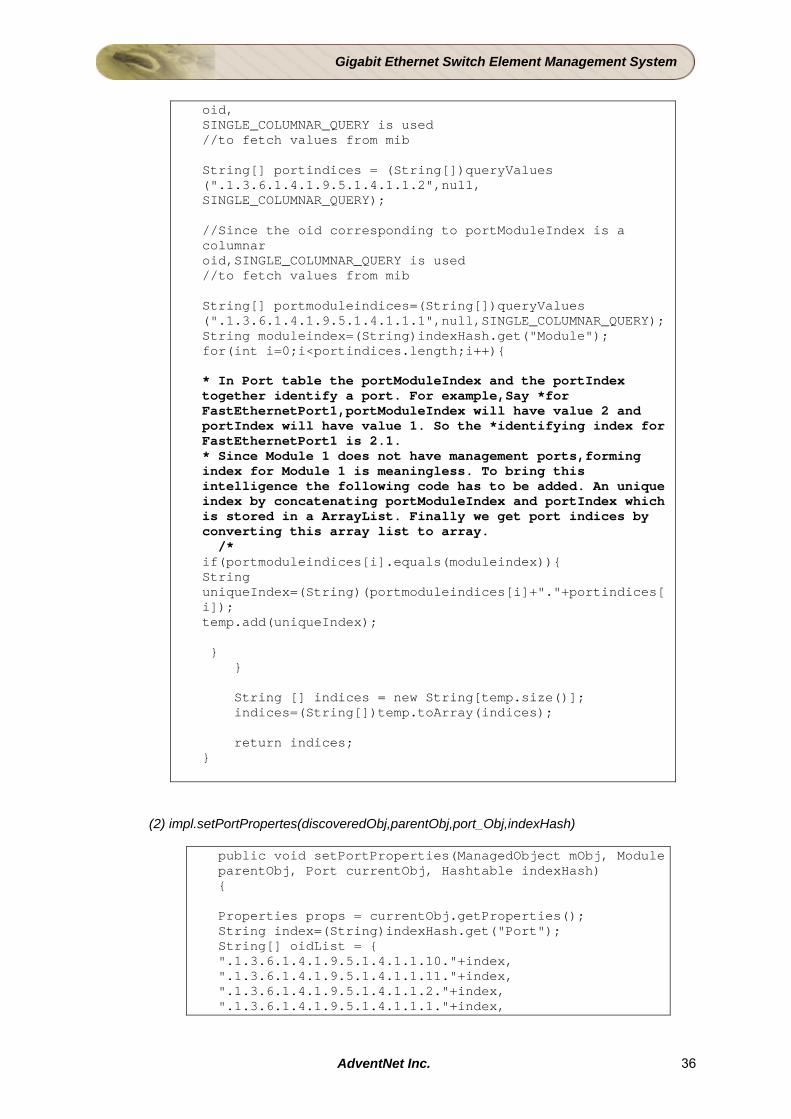
oid, SINGLE_COLUMNAR_QUERY is used //to fetch values from mib String[] portindices = (String[])queryValues (".1.3.6.1.4.1.9.5.1.4.1.1.2",null, SINGLE_COLUMNAR_QUERY); //Since the oid corresponding to portModuleIndex is a columnar oid,SINGLE_COLUMNAR_QUERY is used //to fetch values from mib String[] portmoduleindices=(String[])queryValues (".1.3.6.1.4.1.9.5.1.4.1.1.1",null,SINGLE_COLUMNAR_QUERY); String moduleindex=(String)indexHash.get("Module"); for(int i=0;i<portindices.length;i++){ * In Port table the portModuleIndex and the portIndex together identify a port. For example,Say *for FastEthernetPort1,portModuleIndex will have value 2 and portIndex will have value 1. So the *identifying index for FastEthernetPort1 is 2.1. * Since Module 1 does not have management ports,forming index for Module 1 is meaningless. To bring this intelligence the following code has to be added. An unique index by concatenating portModuleIndex and portIndex which is stored in a ArrayList. Finally we get port indices by converting this array list to array. /* if(portmoduleindices[i].equals(moduleindex)){ String uniqueIndex=(String)(portmoduleindices[i]+"."+portindices[i]); temp.add(uniqueIndex); } } String [] indices = new String[temp.size()]; indices=(String[])temp.toArray(indices); return indices; }
(2) impl.setPortPropertes(discoveredObj,parentObj,port_Obj,indexHash)
public void setPortProperties(ManagedObject mObj, Module parentObj, Port currentObj, Hashtable indexHash) { Properties props = currentObj.getProperties(); String index=(String)indexHash.get("Port"); String[] oidList = { ".1.3.6.1.4.1.9.5.1.4.1.1.10."+index, ".1.3.6.1.4.1.9.5.1.4.1.1.11."+index, ".1.3.6.1.4.1.9.5.1.4.1.1.2."+index, ".1.3.6.1.4.1.9.5.1.4.1.1.1."+index,
AdventNet Inc. 36
Gigabit Ethernet Switch Element Management System
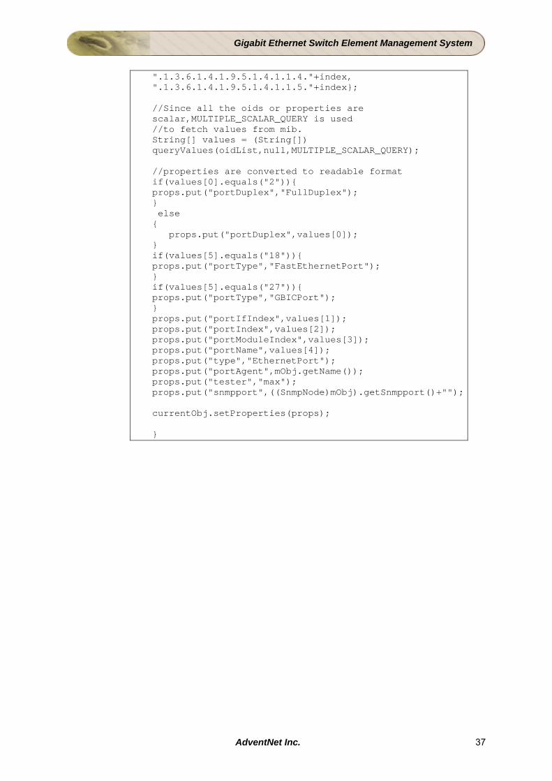
".1.3.6.1.4.1.9.5.1.4.1.1.4."+index, ".1.3.6.1.4.1.9.5.1.4.1.1.5."+index}; //Since all the oids or properties are scalar,MULTIPLE_SCALAR_QUERY is used //to fetch values from mib. String[] values = (String[]) queryValues(oidList,null,MULTIPLE_SCALAR_QUERY); //properties are converted to readable format if(values[0].equals("2")){ props.put("portDuplex","FullDuplex"); } else { props.put("portDuplex",values[0]); } if(values[5].equals("18")){ props.put("portType","FastEthernetPort"); } if(values[5].equals("27")){ props.put("portType","GBICPort"); } props.put("portIfIndex",values[1]); props.put("portIndex",values[2]); props.put("portModuleIndex",values[3]); props.put("portName",values[4]); props.put("type","EthernetPort"); props.put("portAgent",mObj.getName()); props.put("tester","max"); props.put("snmpport",((SnmpNode)mObj).getSnmpport()+""); currentObj.setProperties(props); }
AdventNet Inc. 37

Gigabit Ethernet Switch Element Management System
4.4 Creating Maps to Display GE Switch Devices The GE switch devices discovered need to be represented by images/icons. These representations need to be laid out and displayed in a map. Apart from this, individual switch device is represented as an actual model of the physical equipment. In this view, the GE switch devices with Modules and Ports are displayed in a map. This chapter explains the procedure to achieve the following task using AdventNet Web NMS Studio:
• Creating Map Filter • Customizing Map Filter Code • Creating Other Map Related Files
AdventNet Inc. 38
Gigabit Ethernet Switch Element Management System
4.4.1 Creating Maps to Display GE Switch Aim To create custom map and map containers for the switch objects and their components. This will also include identifying the layout to represent the GE switch device components. GESMapFilter: This is the one which adds GESwitch.netmap and creates the Map Container for GE switch and for two modules (Ethernet, Supervisor) and adds 50 ports (Map Symbol) to the ethernet module container. For details of Creating Map Filter of AdventNet Web NMS Studio, refer to the AdventNet Web NMS Studio documentation. Instructions Follow the steps given below to define a Map filter
Step 1 : Invoking the Map Filter Wizard Click on the node SERVICES > MAP > MAP FILTER. Right-click on the node and select New menu item. Step 2 : Map Filter Details Provide the following details about the Map Filter: Class Name - GESMapFilter
Click Next to proceed. Step 3 : Add the variables Click Next to proceed. Step 4 : Defining Criteria To add the next few criteria, select and right-click Criteria1 node in the tree. Select Create Node option and proceed to add the nodes and their corresponding criteria. Provide the following inputs to define criteria based map representation. Click the Add button to declare Connectors/ Left Operand/ Operator/ Value. Criteria flow Criteria Criteria1 (managedObject instanceof GESwitch) Criteria2 (managedObject instanceof Module) Criteria3 (((Module)managedObject).getModuleType().equals("Ethernet")) Criteria4 (((Module)managedObject).getModuleType().equals("Supervisor")) Criteria5 (managedObject instanceof Port) Criteria6 (((Port)managedObject).getPortType().equals("FastEthernetPort")) Criteria7 (((Port)managedObject).getPortType().equals("GBICPort")) Click the Next button to proceed.
AdventNet Inc. 39

Gigabit Ethernet Switch Element Management System
Step 5: Specify the Filter Properties Click Next. Step 6: View the summary of Criteria and Modified properties Click Next. Step 7: View the Source In the Source screen, check the generated source code for the Criteria and the Properties defined. Click Finish.
Adding custom codes After this, the Java source file is generated by the Wizard. You can add the custom code or modify the existing code of the source using the JMACS editor directly as per your requirement. The details of the custom code added to the Map filter class in discussed in the next topic. Result The map view illustrating the Switch object and their components are ready.
AdventNet Inc. 40
Gigabit Ethernet Switch Element Management System
4.4.2 Customizing Map Filter code This section explains you about how to customize Map to display GE Switch elements of a network. Add the custom code in the Map filter in the appropriate locations as given below: Add the following import statements in GESMapFilter class. import java.util.Vector; import java.util.Properties; import java.rmi.RemoteException; import com.adventnet.nms.mapdb.MapAPI; import com.adventnet.nms.mapdb.MapFilter; import com.adventnet.nms.mapdb.MapSymbol; import com.adventnet.nms.mapdb.MapContainer; import com.adventnet.nms.topodb.ManagedObject; import com.adventnet.nms.tutorials.ges.GESwitch; import com.adventnet.nms.tutorials.ges.Module; import com.adventnet.nms.tutorials.ges.Port; import com.adventnet.nms.util.NmsUtil; import com.adventnet.nms.severity.SeverityInfo; import com.adventnet.nms.store.NmsStorageException; import com.adventnet.management.transaction.UserTransactionException; Add the following variable in the variable declaration portion of the GESMapFilter. String mapName = "GESwitch.netmap"; Add the following variable in the GESMapFilter before the //<Begin_filterMapSymbols_Vector_ManagedObject_MapAPI> tag. MapSymbol mapSym = null; Add the following custom code for Criteria1 after the //<UserCode_Begin_Criteria1_IF_START> tag. try { if(!mapApi.doesTheMapExist(mapName) ) { addGESwitchMap(mapApi); } } catch(RemoteException remote) { } mapSym = createMapObject(managedObject,"container"); ((MapContainer)mapSym).setTopology("$GEModule"); ((MapContainer)mapSym).setCurrentTopology("GEModule"); mapSym.setIconName("geswitch.png"); Add the following code after the //Usercode_Begin_Criteria3_IF_START tag. mapSym = createMapObject(managedObject,"container"); mapSym.setIconName("ethernetmodule.png"); mapSym.setUserProperty("moduleType","ethernet"); ((MapContainer)mapSym).setTopology("$GEEthernetPort"); ((MapContainer)mapSym).setCurrentTopology("GEEthernetPort");
AdventNet Inc. 41
Gigabit Ethernet Switch Element Management System
Add the following code after the //Usercode_Begin_Criteria4_IF_START tag. mapSym = createMapObject(managedObject,"container"); mapSym.setIconName("supervisormodule.png"); mapSym.setUserProperty("moduleType","supervisor"); Add the following code after the //Usercode_Begin_Criteria4_IF_FINISH tag. mapSym.setParentName(managedObject.getParentKey()); Add the following code after the //Usercode_Begin_Criteria6_IF_START tag. mapSym = createMapObject(managedObject,"symbol"); int index = ((Port)managedObject).getPortIndex(); if(index %2 == 0) { mapSym.setIconName("port-down.png"); } else { mapSym.setIconName("port-up.png"); } mapSym.setUserProperty("portno",String.valueOf(index) ); Add the following code after the //Usercode_Begin_Criteria7_IF_START tag. mapSym = createMapObject(managedObject, "symbol"); int index = ((Port)managedObject).getPortIndex(); if(index %2 == 0) { mapSym.setIconName("geport-down.png"); } else { mapSym.setIconName("geport-up.png"); } mapSym.setUserProperty("portno",String.valueOf(index) ); Add the following code after the //Usercode_Begin_Criteria7_IF_FINISH tag. mapSym.setParentName(managedObject.getParentKey()); Add the following custom code, after the //<UserCode_Begin_METHOD_FINISH> tag. if(mapSym!=null) { mapSymbols.addElement(mapSym); } Append the following custom methods in the GESMapFilter. private MapSymbol createMapObject ( ManagedObject managedObject, String type ) { MapSymbol mobj; if ( type.equals("container") ) mobj= new MapContainer(); else mobj = new MapSymbol(); String objname = managedObject.getKey(); mobj.setName( objname ); mobj.setObjName( objname );
AdventNet Inc. 42
Gigabit Ethernet Switch Element Management System
mobj.setLabel( objname ); mobj.setMapName(mapName); if ( managedObject.getManaged() ) { mobj.setParameter("status", String.valueOf( managedObject.getStatus() )); mobj.setParameter("managed", "true"); } else { int unknown = SeverityInfo.getInstance().getUnknown(); mobj.setParameter("status", String.valueOf( unknown )); mobj.setParameter("managed", "false"); } return mobj; } private void addGESwitchMap ( MapAPI mapapi ) throws NmsStorageException, UserTransactionException { Properties p = new Properties(); p.put("name", mapName); p.put("label", "GESwitch"); p.put("autoPlacement", String.valueOf( true )); p.put("anchored", String.valueOf( true )); p.put("treeIconFileName", "images/switch1" + NmsUtil.getImageType()); p.put("topology","$GESwitch"); p.put("currentTopology","GESwitch"); p.put("offSet","0"); p.put("backgroundColor","255,255,255"); p.put("mapSymbolRenderer", "com.adventnet.nms.tutorials.ges.GESwitchMapRenderer"); try { if( mapapi.addMap( mapName, p )) { System.out.println("In GESwitchMapFilter ." + mapName + " created successfully "); } else { System.out.println("In GESwitchMapFilter ." + mapName + " could not be created. ") ; } } catch(NmsStorageException nmse) { throw nmse; } catch(UserTransactionException ute ) { throw ute; } catch ( Exception e ) { } }
AdventNet Inc. 43
Gigabit Ethernet Switch Element Management System
4.4.3 Creating Other Map Related Files Create/Configure the following files for viewing the GE switch device maps. GE Switch Map:
• Creating GE Switch Map Layout Classes • Creating GE Switch Map Symbol Renderer Classes
Creating GE Switch Map Layout This topic explains the layout to be adopted in the GE switch device map. In order to lay the module and ports on the map for the switch, you have to write the following Map Symbol Layout classes. Java Client : GESwitchLayout.java - calculates the size and position for GESwitch map container GEModuleLayout.java - calculates the size and position for Module (Ethernet and Supervisor) map container GEEthernetPortLayout.java - calculates the size and position for all the 50 ports (48 ethernet port and 2 GE port) HTML Client : GESwitchHtmlLayout.java - calculates the size and position for GESwitch map container GEModuleHtmlLayout.java - calculates the size and position for Module (Ethernet and Supervisor) map container GEPortHtmlLayout.java - calculates the size and position for all the 50 ports (48 ethernet port and 2 GE port) Create these symbol layout classes using other files option of the Studio project. Create the file with dummy inputs. Copy the contents from the above given URL and overwrite completely in the newly created file. For details of Working with other files of AdventNet Web NMS Studio, refer to the AdventNet Web NMS Studio documentation. Creating Custom Map Symbol Renderer This topic explains the Map Symbol Renderer to be adopted in the GE Switch device map. You have to create the following Symbol Renderer classes: Java Client : GESwitchMapRenderer.java - Paints the GESwitch map HTML Client : GESwitchHtmlRenderer.java - paints the GE Switch GEModuleHtmlRenderer.java - paints the Module container (Ethernet and Supervisor)
AdventNet Inc. 44

Gigabit Ethernet Switch Element Management System
GEPortHtmlRenderer.java - paints all the 50 ports This, you have to create using other files option of the Studio project. Create the file with dummy inputs. Copy the contents from the above given URL and overwrite completely in the newly created file. For details of Working with other files of AdventNet Web NMS Studio, refer to the AdventNet Web NMS Studio documentation.
AdventNet Inc. 45

Gigabit Ethernet Switch Element Management System
4.5 Performance Monitoring of the GE Switch Aim To monitor the performance of the Switch and the Port Steps Involved
• Editing the polling.conf file to monitor the data collected periodically by the Switch.
• Writing a Poll Filter to collect the "InOctets" and "OutOctets" and thereby calculate interface utilization for the Ports in the Switch.
• Monitoring Utilisation of Switch and Ports from Web NMS Client.
Instructions
Editing the polling.conf Objective : To collect data for Switch.
Step 1 Select the file polling.conf located as a child node of Performance.
Step 2 Enter details as provided below
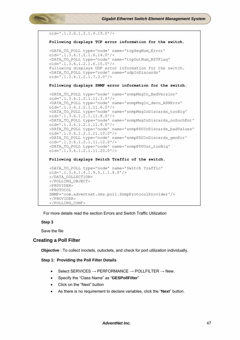
Polling.conf: <POLLING_OBJECT name="GES"> <MATCH_CRITERIA> <MO_PROPERTIES> <STRING_TYPE condition="startswith" value=".1.3.6.1.4.1.9.5.42" property="sysOID"/> </MO_PROPERTIES> </MATCH_CRITERIA> <DATA_COLLECTION pollingPeriod="300"> <DATA_TO_POLL type="node" name="LastRebootTime" oid=".1.3.6.1.2.1.1.3.0"/> Following displays IP traffic and error information for the switch. <DATA_TO_POLL type="node" name="ipInDiscards_HdrErrors" oid=".1.3.6.1.2.1.4.4.0"/> <DATA_TO_POLL type="node" name="ipInDiscards_AddErrors" oid=".1.3.6.1.2.1.4.5.0"/> <DATA_TO_POLL type="node" name="ipInDiscards_UnknownProtocol" oid=".1.3.6.1.2.1.4.7.0"/> <DATA_TO_POLL type="node" name="ipInDiscards_NoProbs" oid=".1.3.6.1.2.1.4.8.0"/> <DATA_TO_POLL type="node" name="ipOutDiscards_NoProbs" oid=".1.3.6.1.2.1.4.11.0"/> <DATA_TO_POLL type="node" name="ipOutDiscards_NoRoutes" oid=".1.3.6.1.2.1.4.12.0"/> <DATA_TO_POLL type="node" name="ipDiscards_FragFails" oid=".1.3.6.1.2.1.4.18.0"/> <DATA TO POLL type="node" name="ipDaFrag NumGen"
AdventNet Inc. 46
Gigabit Ethernet Switch Element Management System
oid=".1.3.6.1.2.1.4.19.0"/> Following displays TCP error information for the switch. <DATA_TO_POLL type="node" name="tcpSegNum_Error" oid=".1.3.6.1.2.1.6.14.0"/> <DATA_TO_POLL type="node" name="tcpOutNum_RSTFlag" oid=".1.3.6.1.2.1.6.15.0"/> Following displays UDP error information for the switch. <DATA_TO_POLL type="node" name="udpInDiscards" oid=".1.3.6.1.2.1.7.3.0"/> Following displays SNMP error information for the switch. <DATA_TO_POLL type="node" name="snmpMsgIn_BadVersion" oid=".1.3.6.1.2.1.11.3.0"/> <DATA_TO_POLL type="node" name="snmpMsgIn_deco_ASNErrs" oid=".1.3.6.1.2.1.11.6.0"/> <DATA_TO_POLL type="node" name="snmpMsgInDiscards_tooBig" oid=".1.3.6.1.2.1.11.8.0"/> <DATA_TO_POLL type="node" name="snmpMsgInDiscards_noSuchEnt" oid=".1.3.6.1.2.1.11.9.0"/> <DATA_TO_POLL type="node" name="snmpPDUInDiscards_badValues" oid=".1.3.6.1.2.1.11.10.0"/> <DATA_TO_POLL type="node" name="snmpPDUInDiscards_genErr" oid=".1.3.6.1.2.1.11.12.0"/> <DATA_TO_POLL type="node" name="snmpPDUOut_tooBig" oid=".1.3.6.1.2.1.11.20.0"/> Following displays Switch Traffic of the switch. <DATA_TO_POLL type="node" name="Switch Traffic" oid=".1.3.6.1.4.1.9.5.1.1.8.0"/> </DATA_COLLECTION> </POLLING_OBJECT> <PROVIDER> <PROTOCOL SNMP="com.adventnet.nms.poll.SnmpProtocolProvider"/> </PROVIDER> </POLLING_CONF>
For more details read the section Errors and Switch Traffic Utilization
Step 3 Save the file
Creating a Poll Filter
Objective : To collect inoctets, outoctets, and check for port utilization individually.
Step 1: Providing the Poll Filter Details
• Select SERVICES → PERFORMANCE → POLLFILTER → New. • Specify the “Class Name” as “GESPollFilter” • Click on the “Next” button • As there is no requirement to declare variables, click the “Next” button.
AdventNet Inc. 47
Gigabit Ethernet Switch Element Management System
Step 2: Defining the Criteria
• Right click on the Code_Builder node. Choose Create Sub Node. Enter the node name as Criteria1.
• Click on the Criteria1 node and click on the Add button. • Choose “managedObject” from the “Instance and Variable List”, so that it gets added
to the “Left Operand” field. • Choose the “instanceof” option for the “Operator” field and Type “Port” in the “Right
Operand” field. • Click on “OK” and click on the “Next” button to proceed.
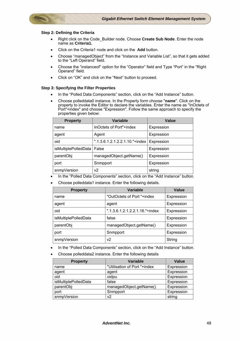
Step 3: Specifying the Filter Properties
• In the “Polled Data Components” section, click on the “Add Instance” button. • Choose polleddata0 instance. In the Property form choose "name". Click on the
property to invoke the Editor to declare the variables. Enter the name as "InOctets of Port"+index" and choose "Expression". Follow the same approach to specify the properties given below:
Property Variable Value name InOctets of Port"+index Expression
agent Agent Expression
oid ".1.3.6.1.2.1.2.2.1.10."+index Expression
isMultiplePolledData False Expression
parentObj managedObject.getName() Expression
port Snmpport Expression
snmpVersion v2 string • In the “Polled Data Components” section, click on the “Add Instance” button. • Choose polleddata1 instance. Enter the following details.
Property Variable Value name "OutOctets of Port "+index Expression
agent agent Expression
oid ".1.3.6.1.2.1.2.2.1.16."+index Expression
isMultiplePolledData false Expression
parentObj managedObject.getName() Expression
port Snmpport Expression
snmpVersion v2 String
• In the “Polled Data Components” section, click on the “Add Instance” button. • Choose polleddata2 instance. Enter the following details
Property Variable Value name "Utilisation of Port "+index Expression agent agent Expression oid oidpu Expression isMultiplePolledData false Expression parentObj managedObject.getName() Expression port Snmpport Expression snmpVersion v2 string
AdventNet Inc. 48
Gigabit Ethernet Switch Element Management System
Note: 1. The property isMultiplePolledData is set to False for all the polled data instances as the data are collected for individual port (not for Switch). 2. The Switch supports Snmp agent version V2c. Click on the “Next” button.
Step 4: Preview of Modified Properties
The modifications done to the properties can be viewed from the “Modified Properties” table. After confirming that the properties got changed as desired, click on “Next”.
Step 5: Viewing the Source The source code for the Poll Filter can be viewed in this screen. Click on “Finish” to create the poll filter.
Result The Poll Filters for collecting the data from the Port is ready. Step 6: Adding User code
Edit the Source. Add the following lines of code after the <UserCode_Begin_Criteria1_IF_START> comment. String agent=((Port)managedObject).getPortAgent(); int index=((Port)managedObject).getPortIndex(); int Snmpport=((Port)managedObject).getSnmpport(); String oidpu="((max(.1.3.6.1.2.1.2.2.1.10."+index+",.1.3.6.1.2.1.2.2.1.16."+index+")*800)/(300*(.1.3.6.1.2.1.2.2.1.5."+index+")))";
Monitoring Utilisation of Switch and Ports from Web NMS Client > Map view and Network Database:
Step1: Associating menus for map symbol and managed objects: Prerequisites Knowledge on how to create Map-Specific Menu and Object specific menu in Java Client Framework is essential. For more details read the section Menu Categorization in Developer Guide. Introduction:
• To associate menus with any particular map symbol or a managed object edit the mapIcon.data and listIcon.data conf files located <GES_Tutorial>/WebNMS/conf directory .The Object-Specific menus displayed for an object selected in a map is different from that displayed when the same object is selected in the Network Database panel table. It is also possible to display more than one Object-Specific menu for the same map symbol in the menu bar, by specifying them for the menuName attribute in the mapIcon.data file.
AdventNet Inc. 49
Gigabit Ethernet Switch Element Management System
Procedure: 1.In the file <GES_Tutorial>/WebNMS/conf/mapIcon.data>, provide the following entries :
<DATA iconName="switch.png" TYPE="GESwitch" menuName="GESwitchmenu"/> <DATA iconName="switchPort.png" TYPE="EthernetPort" menuName="Ethernetportmenu"/> <DATA iconName="switch.png" TYPE="Module" menuName="modulemenu"/>
Note: The file mapIcon.data file must be opened only in a text editor separately.
2. In the file <GES_Tutotrial>/WebNMS/conf/listIcon.data>, provide the following entries :
<DATA CRITICAL_IMG="hub_red.png" TYPE="GESwitch" WARNING_IMG="hub_cyan.png" CLEAR_IMG="hub_green.png" MINOR_IMG="hub_yellow.png" MENU="GESwitchmenu" UNKNOWN_IMG="hub_gray.png" MAJOR_IMG="hub_orange.png"/> <DATA CRITICAL_IMG="pc_red.png" TYPE="Module" WARNING_IMG="pc_cyan.png" CLEAR_IMG="pc_green.png" MINOR_IMG="pc_yellow.png" MENU="modulemenu" UNKNOWN_IMG="pc_gray.png" MAJOR_IMG="pc_orange.png"/> <DATA CRITICAL_IMG="hub_red.png" TYPE="EthernetPort" WARNING_IMG="hub_cyan.png" CLEAR_IMG="hub_green.png" MINOR_IMG="hub_yellow.png" MENU="Ethernetportmenu" UNKNOWN_IMG="hub_gray.png" MAJOR_IMG="hub_orange.png"/>
Step 2: Writing menu configuration files in Studio: Prerequisites Knowledge on how to create Menu Actions is essential. For more details read the section Menu File Organization and Menu Actions in Developer Guide. Introduction:
• The Object-Specific menus are written in XML format in the respective menu configuration files (.xml files). For every managed object, a corresponding menu configuration file is created containing the related Object-Specific menu items.
• The Object-Specific menus can be categorized into
• menus displayed for a map symbol and
• menus displayed for a managed object. In short, different menus are displayed for the same managed object based on the panel (i.e., Map or Network Database) from where they are selected. Procedure: For map symbols (i.e., managed objects selected in the map), the corresponding menu configuration files should be written and placed in <GES_Tutorial>/WebNMS/users/<username>/mapmenus directory . Since three different menus are asssociated each with GESwitch,Module,Port, the following XML files have to be written.
AdventNet Inc. 50
Gigabit Ethernet Switch Element Management System
GESwitch.xml
<?xml version="1.0" encoding="UTF-8"?> <!DOCTYPE MENU SYSTEM "menu.dtd"> <MENU name="Plot"> <MENU-ITEM name="Collected Statistic" accelerator_modifier="CNTRL" shortcut_key="P" action_command="INVOKE_CLASS:com.adventnet.nms.tutorials.ges. GESwitchCollectedInvoker" accelerator_key="O"/> <MENU-ITEM name="Current Statistic" accelerator_modifier="CNTRL-SHIFT" shortcut_key="C" action_command="INVOKE_CLASS:com.adventnet.nms.tutorials.ges. GESwitchCurrentInvoker" accelerator_key="P"/> </MENU>
Ethernetportmenu.xml
?xml version="1.0" encoding="UTF-8"?> <!DOCTYPE MENU SYSTEM "menu.dtd"> <MENU name="Plot"> <MENU-ITEM name="Collected Statistic" accelerator_modifier= "CNTRL" shortcut_key="P" action_type="INVOKE_CLASS" action_value="com.adventnet.nms.tutorials.ges. EthernetPortCollectedInvoker?portIndex=${portIndex}& portAgent=${portAgent}" accelerator_key="O"/> <MENU-ITEM name="Current Statistic" accelerator_modifier= "CNTRL-SHIFT" shortcut_key="C" action_type="INVOKE_CLASS" action_value="com.adventnet.nms.tutorials.ges. EthernetPortCurrentInvoker?portIndex= ${portIndex}&portAgent=${portAgent}" accelerator_key="P"/> </MENU>
modulemenu.xml
?xml version="1.0" encoding="UTF-8"?> <!DOCTYPE MENU SYSTEM "menu.dtd"> <MENU name="Object" owner="root" group="users"> <MENU-ITEM name="Manage"> <OPERATION name="Manage And Unmanage Objects"/> <JAVA-UI action_type="function" action_value="Manage"> </JAVA-UI> <HTML-UI action_value="/map/manageUnmanage.do?keys=${name} &managed=true&viewId=${viewId}&displayName=${displayName}" action_type="rightside"/> </MENU-ITEM> <MENU-ITEM name="Update Status" action_type="function" action_value="Update Status"> </MENU-ITEM> </MENU>
For managed objects selected from the table of the Network Database panel, the corresponding menu configuration file should be written and placed in <GES_Tutorial>/WebNMS/users/<usename>/listmenus directory.
AdventNet Inc. 51

Gigabit Ethernet Switch Element Management System
GESwitchmenu.xml
<?xml version="1.0" encoding="UTF-8"?> <!DOCTYPE MENU SYSTEM "listmenu.dtd"> <MENU name="GESwitch" shortcut_key="P" owner="root" group="users"> <MENU name="Plot"> <MENU-ITEM name="Collected Statistic" action_type= "INVOKE_CLASS" action_value="com.adventnet.nms.tutorials.ges. GESwitchCollectedInvoker"> </MENU-ITEM> <MENU-ITEM name="Current Statistic" action_type= "INVOKE_CLASS" action_value="com.adventnet.nms.tutorials.ges. GESwitchCurrentInvoker"> </MENU-ITEM> </MENU> <MENU-ITEM name="SEPARATOR"/> <MENU-ITEM name="Managed Object Properties" action_type= "function" action_value="Managed Object Properties"> </MENU-ITEM> <MENU-ITEM name="SEPARATOR"/> <MENU-ITEM name="Delete Object and Traces" ACTION-ON-NO-PRIVILEGE="HIDE"> <OPERATION name="Delete Object"/> <HTML-UI action_value="/topo/deleteObject.do?keys=${name} &viewId=${viewId}&displayName=${displayName} &isAscending=${isAscending}&FROM_INDEX=${FROM_INDEX} &PAGE_NUMBER=${PAGE_NUMBER}&orderByColumn=${orderByColumn} &viewLength=${viewLength}" action_type="rightside"/> <JAVA-UI action_type="INVOKE_CLASS" action_value="com.adventnet.nms.mapui.DeleteMO?name=${name} &type=${type}&isContainer=${isContainer} &isGroup=${isGroup}"> </JAVA-UI> </MENU-ITEM> <MENU-ITEM name="SEPARATOR"/> </MENU>
Ethernetportmenu.xml
<?xml version="1.0" encoding="UTF-8"?> <!DOCTYPE MENU SYSTEM "listmenu.dtd"> <MENU name="EthernetPort" shortcut_key="P" owner="root" group="users"> <MENU name="Plot"> <MENU-ITEM name="Collected Statistic" action_type= "INVOKE_CLASS" action_value="com.adventnet.nms.tutorials. ges.EthernetPortCollectedInvoker?portIndex=${portIndex} &portAgent=${portAgent}"> </MENU-ITEM> <MENU-ITEM name="Current Statistic" action_type= "INVOKE_CLASS" action_value="com.adventnet.nms.tutorials. ges.EthernetPortCurrentInvoker?portIndex=${portIndex} &portAgent=${portAgent}"> </MENU-ITEM> </MENU> <MENU-ITEM name="SEPARATOR"/> <MENU-ITEM name="Managed Object Properties" action_type= "function" action_value="Managed Object Properties"> </MENU-ITEM> <MENU-ITEM name="SEPARATOR"/>
AdventNet Inc. 52
Gigabit Ethernet Switch Element Management System
<MENU-ITEM name="Delete Object and Traces" ACTION-ON-NO-PRIVILEGE="HIDE"> <OPERATION name="Delete Object"/> <HTML-UI action_value="/topo/deleteObject.do?keys=${name} &viewId=${viewId}&displayName=${displayName} &isAscending=${isAscending}&FROM_INDEX=${FROM_INDEX} &PAGE_NUMBER=${PAGE_NUMBER}&orderByColumn= ${orderByColumn}&viewLength=${viewLength}" action_type="rightside"/> <JAVA-UI action_type="INVOKE_CLASS" action_value="com.adventnet.nms.mapui.DeleteMO?name= ${name}&type=${type}&isContainer=${isContainer} &isGroup=${isGroup}"> </JAVA-UI> </MENU-ITEM> <MENU-ITEM name="SEPARATOR"/> </MENU>
modulemenu.xml
<?xml version="1.0" encoding="UTF-8"?> <!DOCTYPE MENU SYSTEM "listmenu.dtd"> <MENU name="Module" owner="root" group="users"> <!-- <MENU-ITEM name="Manage"> <OPERATION name="Manage And Unmanage Objects"/> <JAVA-UI action_type="function" action_value="Manage"> </JAVA-UI> <HTML-UI action_value="/topo/manageUnmanage.do?keys= ${name}&managed=true&viewId=${viewId}& displayName=${displayName}&orderByColumn=${orderByColumn} &isAscending=${isAscending}&FROM_INDEX=${FROM_INDEX} &PAGE_NUMBER=${PAGE_NUMBER}" action_type="rightside"/> </MENU-ITEM> <MENU-ITEM name="Update Status" action_type="function" action_value="PollStatus"> </MENU-ITEM> <MENU-ITEM name="SEPARATOR"/> --> <MENU-ITEM name="Managed Object Properties" action_type="function" action_value="Managed Object Properties"> </MENU-ITEM> <MENU-ITEM name="SEPARATOR"/> <MENU-ITEM name="Delete Object and Traces" ACTION-ON-NO-PRIVILEGE="HIDE"> <OPERATION name="Delete Object"/> <HTML-UI action_value="/topo/deleteObject.do?keys=${name}& viewId=${viewId}&displayName=${displayName}& isAscending=${isAscending}&FROM_INDEX=${FROM_INDEX} &PAGE_NUMBER=${PAGE_NUMBER}&orderByColumn= ${orderByColumn}&viewLength=${viewLength}" action_type="rightside"/> <JAVA-UI action_type="INVOKE_CLASS" action_value="com.adventnet.nms.mapui.DeleteMO?name= ${name}&type=${type}&isContainer=${isContainer} &isGroup=${isGroup}"> </JAVA-UI> </MENU-ITEM> <MENU-ITEM name="SEPARATOR"/> </MENU>
AdventNet Inc. 53
Gigabit Ethernet Switch Element Management System
Step 3: Writing User Classes required for menu functions: Prerequisites: Knowledge in Writing your own class for menu actions. Knowledge of the CustomClassInterface Instructions: Write the following files by right clicking the "OtherFiles" node in Studio and choosing "File Type" as client java
1. User class to show current statistics of GESwitch (GESwitchCurrentInvoker.java): 2. User class to show collected statistics of GESwitch (GESwitchCollectedInvoker.java) 3. User class to show current statistics of EthernerPort
(EthernetPortCurrentInvoker.java) 4. User class to show collected statistics of EthernerPort
(EthernetPortCollectedInvoker.java)
AdventNet Inc. 54

Gigabit Ethernet Switch Element Management System
4.6 Fault Management 4.6.1 Creating a Trap Filter Aim To provide complete fault management capability to the EMS through effective Trap handling of the GE Switch. Instructions
Step 1: Invoking the Trap Filter Wizard 1. Select the node Services > Fault > Trap Filter. Right-click Trap Filter node and select
New menu item. This invokes Trap Filter Wizard.
Step 2 : Filter Details
Provide the following details about the Trap Filter: 1. Enter the Class Name as "GESTrapFilter". 2. Select "com.adventnet.nms.eventdb.Event" from Event Class combo box. 3. Click Next to proceed to next screen.
Step 3 : Defining Variables 1. Create the following nodes under Code_Builder node as given below by right-
clicking the node and select Create SubNode or Create Node. Code_Builder
• Criteria1 • Criteria2 • Criteria3 • Criteria4
2. Click Next to proceed to next screen.
Step 4: Defining Criteria 1. Ensure Generate criteria based on given parameters radio button is selected
under Criteria Options field for all the nodes in the tree. 2. Select the options corresponding to each node in Criteria for Traps to Match panel
as given below in the table. To select the options in Criteria for Traps to Match panel for Criteria1 node, follow the steps given below:
1. Select Criteria1 node and select Match any of the following radio button. 2. Select "Trap OID" command (first column is for command) in the first row.
Select "equals" operator in second column and provide OID as "1.3.6.1.4.1.9.5.0.3" in third column.
Similarly, select the options for other nodes.
Criteria Match Criteria (Match Any or Match all of the following) Command Operator Value
Criteria1 Match any of the following Trap OID equals 1.3.6.1.4.1.9.5.0.3
Criteria2 Match any of the following Trap OID equals 1.3.6.1.4.1.9.5.0.4
Criteria3 Match any of the following Trap OID equals 1.3.6.1.6.3.1.1.5.3
Criteria4 Match any of the following Trap OID equals 1.3.6.1.6.3.1.1.5.4
3. Click Next to proceed to next screen.
AdventNet Inc. 55
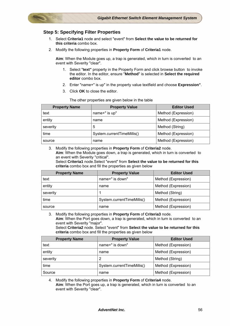
Gigabit Ethernet Switch Element Management System
Step 5: Specifying Filter Properties
1. Select Criteria1 node and select "event" from Select the value to be returned for this criteria combo box.
2. Modify the following properties in Property Form of Criteria1 node. Aim: When the Module goes up, a trap is generated, which in turn is converted to an event with Severity "clear".
1. Select "text" property in the Property Form and click browse button to invoke the editor. In the editor, ensure "Method" is selected in Select the required editor combo box.
2. Enter "name+" is up" in the property value textfield and choose Expression". 3. Click OK to close the editor.
The other properties are given below in the table
Property Name Property Value Editor Used text name+" is up" Method (Expression)
entity name Method (Expression)
severity 5 Method (String)
time System.currentTimeMillis() Method (Expression)
source name Method (Expression)
3. Modify the following properties in Property Form of Criteria2 node. Aim: When the Module goes down, a trap is generated, which in turn is converted to an event with Severity "critical". Select Criteria1 node.Select "event" from Select the value to be returned for this criteria combo box and fill the properties as given below
Property Name Property Value Editor Used text name+" is down" Method (Expression)
entity name Method (Expression)
severity 1 Method (String)
time System.currentTimeMillis() Method (Expression)
source name Method (Expression)
3. Modify the following properties in Property Form of Criteria3 node. Aim: When the Port goes down, a trap is generated, which in turn is converted to an event with Severity "major". Select Criteria2 node. Select "event" from Select the value to be returned for this criteria combo box and fill the properties as given below
Property Name Property Value Editor Used text name+" is down" Method (Expression)
entity name Method (Expression)
severity 2 Method (String)
time System.currentTimeMillis() Method (Expression)
Source name Method (Expression)
4. Modify the following properties in Property Form of Criteria4 node. Aim: When the Port goes up, a trap is generated, which in turn is converted to an event with Severity "clear".
AdventNet Inc. 56
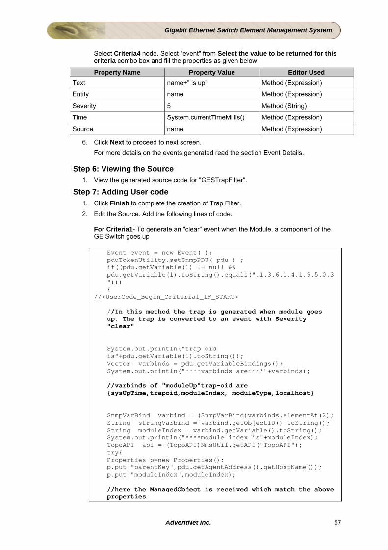
Gigabit Ethernet Switch Element Management System
Select Criteria4 node. Select "event" from Select the value to be returned for this criteria combo box and fill the properties as given below
Property Name Property Value Editor Used Text name+" is up" Method (Expression)
Entity name Method (Expression)
Severity 5 Method (String)
Time System.currentTimeMillis() Method (Expression)
Source name Method (Expression)
6. Click Next to proceed to next screen. For more details on the events generated read the section Event Details.
Step 6: Viewing the Source
1. View the generated source code for "GESTrapFilter".
Step 7: Adding User code 1. Click Finish to complete the creation of Trap Filter. 2. Edit the Source. Add the following lines of code.
For Criteria1- To generate an "clear" event when the Module, a component of the GE Switch goes up
Event event = new Event( ); pduTokenUtility.setSnmpPDU( pdu ) ; if((pdu.getVariable(1) != null && pdu.getVariable(1).toString().equals(".1.3.6.1.4.1.9.5.0.3"))) {
//<UserCode_Begin_Criteria1_IF_START>
//In this method the trap is generated when module goes up. The trap is converted to an event with Severity "clear" System.out.println("trap oid is"+pdu.getVariable(1).toString()); Vector varbinds = pdu.getVariableBindings(); System.out.println("****varbinds are****"+varbinds); //varbinds of "moduleUp"trap-oid are {sysUpTime,trapoid,moduleIndex, moduleType,localhost} SnmpVarBind varbind = (SnmpVarBind)varbinds.elementAt(2); String stringVarbind = varbind.getObjectID().toString(); String moduleIndex = varbind.getVariable().toString(); System.out.println("****module index is"+moduleIndex); TopoAPI api = (TopoAPI)NmsUtil.getAPI("TopoAPI"); try{ Properties p=new Properties(); p.put("parentKey",pdu.getAgentAddress().getHostName()); p.put("moduleIndex",moduleIndex); //here the ManagedObject is received which match the above properties
AdventNet Inc. 57

Gigabit Ethernet Switch Element Management System
Vector v=api.getObjectNamesWithProps(p); for (Enumeration e = v.elements() ; e.hasMoreElements() ;) { String name=e.nextElement().toString(); System.out.println("name inside moduleup is "+name); String parentKey=pdu.getAgentAddress().getHostName(); System.out.println("parent key is "+parentKey);
For Criteria2 - To generate a "critical" event when the Module, a component of the GE Switch goes down
//<UserCode_End_Criteria1_IF_END> if((pdu.getVariable(1) != null && pdu.getVariable(1).toString().equals(".1.3.6.1.4.1.9.5.0.4"))) { //<UserCode_Begin_Criteria2_IF_START> //In this method the trap generated when module goes down is converted to an event with Severity "Critical" System.out.println("trap oid is"+pdu.getVariable(1).toString()); Vector varbinds = pdu.getVariableBindings(); System.out.println("****varbinds are****"+varbinds); //varbinds of "moduleDown" trap-oid are {sysUpTime,trapoid,moduleIndex,moduleType,localhost} SnmpVarBind varbind = (SnmpVarBind)varbinds.elementAt(2); String stringVarbind = varbind.getObjectID().toString(); String moduleIndex = varbind.getVariable().toString(); System.out.println("****module index is****"+moduleIndex); TopoAPI api = (TopoAPI)NmsUtil.getAPI("TopoAPI"); try{ Properties p=new Properties(); p.put("parentKey",pdu.getAgentAddress().getHostName()); p.put("moduleIndex",moduleIndex); Vector v=api.getObjectNamesWithProps(p); for (Enumeration e = v.elements() ; e.hasMoreElements() ;) { String name=e.nextElement().toString(); System.out.println("name inside module down is "+name); String parentKey=pdu.getAgentAddress().getHostName(); System.out.println("parent key is "+parentKey);
For Criteria3 - To generate a "major" event when the Port a component of the GE Switch goes down
//<UserCode_End_Criteria2_IF_END> if((pdu.getVariable(1) != null && pdu.getVariable(1).toString().equals(".1.3.6.1.6.3.1.1.5.3"))) {
AdventNet Inc. 58
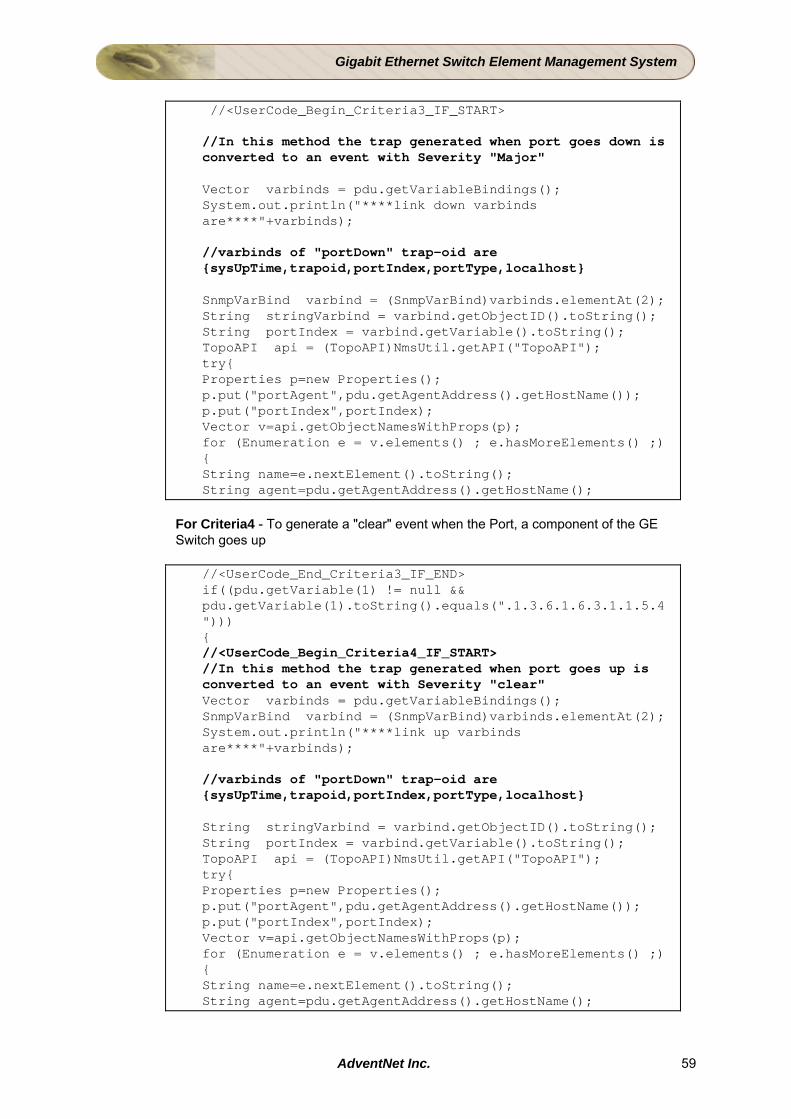
Gigabit Ethernet Switch Element Management System
//<UserCode_Begin_Criteria3_IF_START> //In this method the trap generated when port goes down is converted to an event with Severity "Major" Vector varbinds = pdu.getVariableBindings(); System.out.println("****link down varbinds are****"+varbinds); //varbinds of "portDown" trap-oid are {sysUpTime,trapoid,portIndex,portType,localhost} SnmpVarBind varbind = (SnmpVarBind)varbinds.elementAt(2); String stringVarbind = varbind.getObjectID().toString(); String portIndex = varbind.getVariable().toString(); TopoAPI api = (TopoAPI)NmsUtil.getAPI("TopoAPI"); try{ Properties p=new Properties(); p.put("portAgent",pdu.getAgentAddress().getHostName()); p.put("portIndex",portIndex); Vector v=api.getObjectNamesWithProps(p); for (Enumeration e = v.elements() ; e.hasMoreElements() ;) { String name=e.nextElement().toString(); String agent=pdu.getAgentAddress().getHostName();
For Criteria4 - To generate a "clear" event when the Port, a component of the GE Switch goes up
//<UserCode_End_Criteria3_IF_END> if((pdu.getVariable(1) != null && pdu.getVariable(1).toString().equals(".1.3.6.1.6.3.1.1.5.4"))) { //<UserCode_Begin_Criteria4_IF_START> //In this method the trap generated when port goes up is converted to an event with Severity "clear" Vector varbinds = pdu.getVariableBindings(); SnmpVarBind varbind = (SnmpVarBind)varbinds.elementAt(2); System.out.println("****link up varbinds are****"+varbinds); //varbinds of "portDown" trap-oid are {sysUpTime,trapoid,portIndex,portType,localhost} String stringVarbind = varbind.getObjectID().toString(); String portIndex = varbind.getVariable().toString(); TopoAPI api = (TopoAPI)NmsUtil.getAPI("TopoAPI"); try{ Properties p=new Properties(); p.put("portAgent",pdu.getAgentAddress().getHostName()); p.put("portIndex",portIndex); Vector v=api.getObjectNamesWithProps(p); for (Enumeration e = v.elements() ; e.hasMoreElements() ;) { String name=e.nextElement().toString(); String agent=pdu.getAgentAddress().getHostName();
AdventNet Inc. 59

Gigabit Ethernet Switch Element Management System
Result The Trap Filter will generate events
• when the "Module is Down" • when "Module is up" • when "Port is down" • when "Port is up"
AdventNet Inc. 60
Gigabit Ethernet Switch Element Management System
4.7 Building configuration Screen - An Introduction Introduction In order to optimize the functioning of the GESwitch, and its components, it is essential to configure certain parameters of the Switch online. This has to be achieved by building Configuration screens. The screens have to be built separately using Configuration Wizard of Client Builder. The compiled screens, must be imported as a NAR file into the Studio project. The Approach To configure the Switch, the configuration mechanism has been classified as
• Switch Configuration
• Port Configuration.
Both these configuration screens have to be launched from the map menu of the Web NMS client. Apart from the above two screens for general configuration, another screen called the SwitchPortDetails has to be built. Map Symbol Details Switch For the Switch map symbol two menu items should be created
• Configure Device
• Port Details
Configure Device menu to configure the properties of the Switch like sysname, syslocation etc and Port Details menu to view the information of all the ports as well as to configure the ports. Port For the Port map symbol one menu item has to be created
• Configure Port
Configure Port menu to configure the port. This menu item will in turn launch a configuration screen similar to the one which can be launched using Edit button of the Port Details screen for the Switch. For the Switch Configuration screen a separate screen called GESwichConfiguration is created. The properties of Switch used in this screen are sysDescr, sysObjectID, sysUpTime, sysName, sysLocation, sysServices and sysReset. For querying the values of the properties clientproperties are added to every component. To learn the basics on using Configuration Wizard and configuration-related terms and definitions, refer to the topic Building Configuration Management Applications. Opening Configuration Wizard Open the AdventNet Configuration Wizard using the file startConfigurationWizard.bat/sh present in the <Client Builder Home>/bin directory. The <Client Builder Home> is the Client Builder directory present under <Web NMS Home>/StudioTools directory.
AdventNet Inc. 61
Gigabit Ethernet Switch Element Management System
Creating the Project and Loading Device Information
• Select File > New > Project to invoke the "Project Details" dialog to create a new configuration project.
• Provide the "Project Name" field with the value "GES_Config" if it does not exist.
• Provide the "Package Name" field with the value "com.adventnet.nms.tutorials.ges". • Click OK to create the project in the projects folder under the <Client Builder Home>. You can
find the project named "GES_Config" in the project tree.
• Load the CISCO-STACK_MIB under the <Client Builder Home>/mibs directory using the load XML/MIB button .
Note: The GES_Config project built using the steps mentioned in this tutorial exists by default (under <Client Builder Home>/projects). You can open the existing GES_Config project and package it as a NAR and proceed. Otherwise, you must back up the existing eBonConfig project into some other directory and create a new GES_Config project following the steps given above. Or you may create a project with different name and follow the steps given to create the project.
Steps Involved in Building Project and Packaging the Application The steps involved in building the Configuration Management Application, Packaging the Application as NAR, and importing the NAR into Web NMS Studio are given below.
• Building Switch Configuration Screen
• Building Port Details Screen
• Building Port Configuration Screen
• Packaging the Config Screens
AdventNet Inc. 62
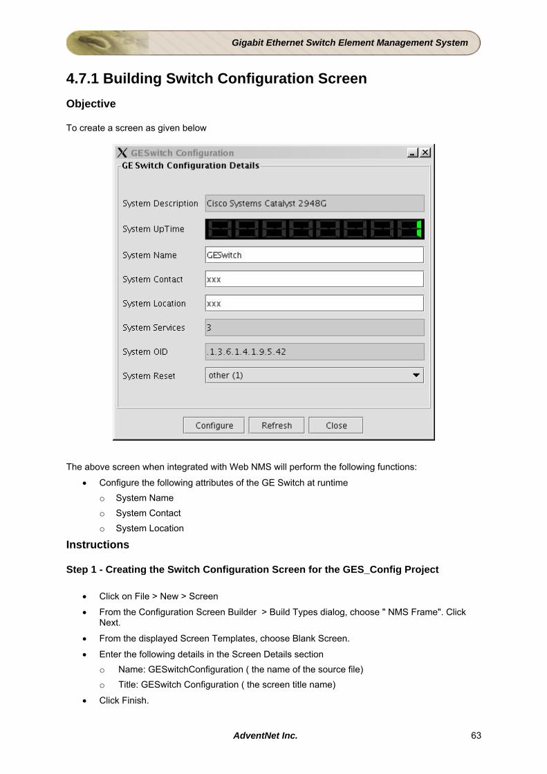
Gigabit Ethernet Switch Element Management System
4.7.1 Building Switch Configuration Screen Objective To create a screen as given below
The above screen when integrated with Web NMS will perform the following functions:
• Configure the following attributes of the GE Switch at runtime o System Name o System Contact o System Location
Instructions Step 1 - Creating the Switch Configuration Screen for the GES_Config Project
• Click on File > New > Screen
• From the Configuration Screen Builder > Build Types dialog, choose " NMS Frame". Click Next.
• From the displayed Screen Templates, choose Blank Screen.
• Enter the following details in the Screen Details section o Name: GESwitchConfiguration ( the name of the source file) o Title: GESwitch Configuration ( the screen title name)
• Click Finish.
AdventNet Inc. 63

Gigabit Ethernet Switch Element Management System
Step 2 - Defining Layout
• Right click on the blank screen and choose Layout > Border Layout.
• Drop 2 JPanels - (a) Centre and (b) South
• Right-click on the Centre panel and choose Layout > Border Layout.
• Place the cursor in the centre panel and drop another JPanel. This is to display the Title "GESwitch Configuration Details" for the Screen.
• Double click on the innermost panel and from the Select Border combo box choose, Titled Border.
• For the Titled Border choose/enter the following properties o Border: Etched Border o Title String: GE Switch Configuration o Title Font : Choose as desired o Title Colour : Choose as desired o Click Apply. o Right Click on the inner panel and choose Layout > GrigBag Layout.
Step 3 - Laying out of Labels and other Fields • Drop a JLabel from the SwingBeans.list tab of BeansPalette and the instance name will be
"JLabel1" and provide "text" property value "System Description" in the Property Form. Similarly drop seven more JLabels and change their properties in Property Form as given in the table below
Instance Name Text Property JLabel2 System UpTime JLabel3 System Name JLabel4 System Services JLabel5 System OID JLabel6 System Contact JLabel7 System Location JLabel8 System Reset
Step 4 - Configuring the Representations
• Expand the RFC1213-MIB node in the XML tree and scroll down to RFC1213-MIB > org > dod > internet > mgmt > mib-2 > system.
• Click and drop the "sysDescr" representation (View1 node under this node) and retain the instance name as JTextField1. Similarly drop the representation for the nodes given in the table below and retain/change the their respective instance names.
Representation for the Node Instance Name sysUpTime DigDisp1 sysName sysName_txt
sysServices JTextField2 sysObjectID JTextField3 sysContact sysContact_txt sysLocation sysLocation_txt
AdventNet Inc. 64

Gigabit Ethernet Switch Element Management System
a. Drop a JComboBox from the SwingBeans.list tab of BeansPalette and change the instance name to "sysReset_cmb".
b. Select the JComboBox and right-click on it. c. Select ProtocolPropertyForm > New Client Property. Client Property for ::
sysReset_cmb screen pops-up. Expand the CISCO-STACK-MIB node in the XML tree and scroll down to CISCO-STACK-MIB > workgroup > ciscoStackMIB > systemGrp.
d. Select sysReset node and click the (Add to Selected Nodes List) button. Select the User Code radio button.
e. Copy the following code in the User Code area. if (sysReset ==1) { sysReset_cmb.setSelectedIndex(0); } else if (sysReset ==2) { sysReset_cmb.setSelectedIndex(1); } else { sysReset_cmb.setSelectedIndex(2); }
f. Click OK.
Step 5 - Customizing the Layout
• Invoke the "GridBag Layout Customizer" window for the "JPanel1" by right-clicking the screen and select "Layout Properties".
• In the GridBag Layout Customizer, set the following properties for all the components:
Property Value Fill Horizontal Anchor Center
• Arrange the components in the "GridBag Layout Customizer" window as given below
Grid Component (Identified with Instance Name)
GridX GridY Insets WeightX
JLabel1 0 0,10,10,0 0.02 JLabel2 1 0,10,10,0 0.02 JLabel3 2 0,10,10,0 0 JLabel4
0
3 0,10,0,0 0 JTextField1 0 0,10,0,0 0.02
DigDisp1 1 0,10,0,0 0.02 sysName_txt 2 0,10,0,0 0 JTextField2
1
3 0,10,0,0 0 JLabel5 0 0,10,0,0 0.02
JLabel6 2
1 0,10,0,0 0.02
AdventNet Inc. 65
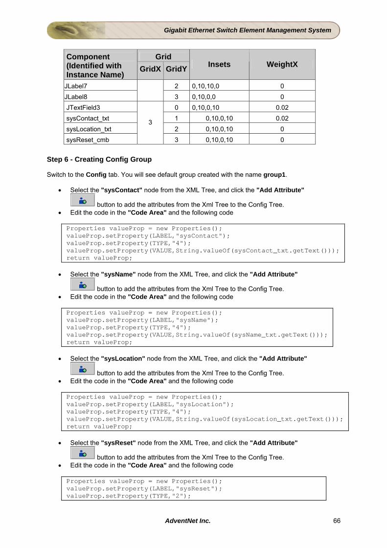
Gigabit Ethernet Switch Element Management System
Grid Component
(Identified with Instance Name)
GridX GridY Insets WeightX
JLabel7 2 0,10,10,0 0 JLabel8
3 0,10,0,0 0
JTextField3 0 0,10,0,10 0.02 sysContact_txt 1 0,10,0,10 0.02 sysLocation_txt 2 0,10,0,10 0 sysReset_cmb
3
3 0,10,0,10 0
Step 6 - Creating Config Group Switch to the Config tab. You will see default group created with the name group1.
• Select the "sysContact" node from the XML Tree, and click the "Add Attribute"
button to add the attributes from the Xml Tree to the Config Tree. • Edit the code in the "Code Area" and the following code Properties valueProp = new Properties(); valueProp.setProperty(LABEL,"sysContact"); valueProp.setProperty(TYPE,"4"); valueProp.setProperty(VALUE,String.valueOf(sysContact_txt.getText())); return valueProp;
• Select the "sysName" node from the XML Tree, and click the "Add Attribute"
button to add the attributes from the Xml Tree to the Config Tree. • Edit the code in the "Code Area" and the following code
Properties valueProp = new Properties(); valueProp.setProperty(LABEL,"sysName"); valueProp.setProperty(TYPE,"4"); valueProp.setProperty(VALUE,String.valueOf(sysName_txt.getText())); return valueProp;
• Select the "sysLocation" node from the XML Tree, and click the "Add Attribute"
button to add the attributes from the Xml Tree to the Config Tree. • Edit the code in the "Code Area" and the following code Properties valueProp = new Properties(); valueProp.setProperty(LABEL,"sysLocation"); valueProp.setProperty(TYPE,"4"); valueProp.setProperty(VALUE,String.valueOf(sysLocation_txt.getText())); return valueProp;
• Select the "sysReset" node from the XML Tree, and click the "Add Attribute"
button to add the attributes from the Xml Tree to the Config Tree. • Edit the code in the "Code Area" and the following code Properties valueProp = new Properties(); valueProp.setProperty(LABEL,"sysReset"); valueProp.setProperty(TYPE,"2");
AdventNet Inc. 66
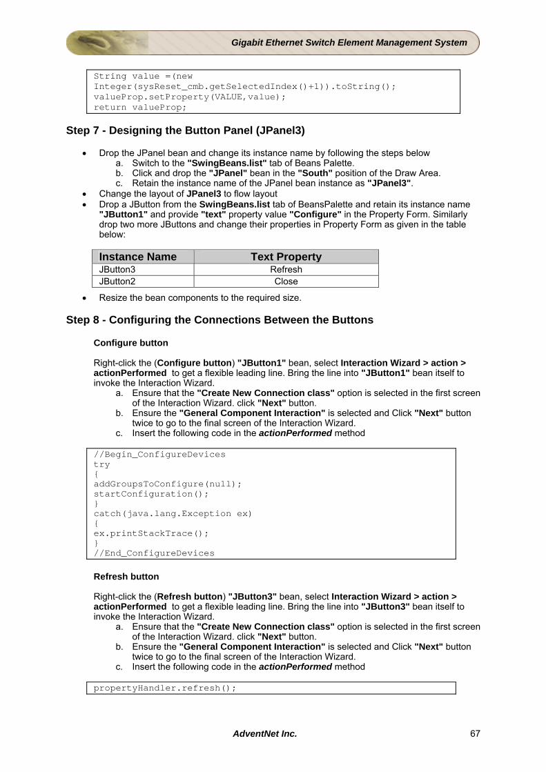
Gigabit Ethernet Switch Element Management System
String value =(new Integer(sysReset_cmb.getSelectedIndex()+1)).toString(); valueProp.setProperty(VALUE,value); return valueProp;
Step 7 - Designing the Button Panel (JPanel3)
• Drop the JPanel bean and change its instance name by following the steps below a. Switch to the "SwingBeans.list" tab of Beans Palette. b. Click and drop the "JPanel" bean in the "South" position of the Draw Area. c. Retain the instance name of the JPanel bean instance as "JPanel3".
• Change the layout of JPanel3 to flow layout • Drop a JButton from the SwingBeans.list tab of BeansPalette and retain its instance name
"JButton1" and provide "text" property value "Configure" in the Property Form. Similarly drop two more JButtons and change their properties in Property Form as given in the table below:
Instance Name Text Property JButton3 Refresh JButton2 Close
• Resize the bean components to the required size. Step 8 - Configuring the Connections Between the Buttons
Configure button Right-click the (Configure button) "JButton1" bean, select Interaction Wizard > action > actionPerformed to get a flexible leading line. Bring the line into "JButton1" bean itself to invoke the Interaction Wizard.
a. Ensure that the "Create New Connection class" option is selected in the first screen of the Interaction Wizard. click "Next" button.
b. Ensure the "General Component Interaction" is selected and Click "Next" button twice to go to the final screen of the Interaction Wizard.
c. Insert the following code in the actionPerformed method
//Begin_ConfigureDevices try { addGroupsToConfigure(null); startConfiguration(); } catch(java.lang.Exception ex) { ex.printStackTrace(); } //End_ConfigureDevices
Refresh button Right-click the (Refresh button) "JButton3" bean, select Interaction Wizard > action > actionPerformed to get a flexible leading line. Bring the line into "JButton3" bean itself to invoke the Interaction Wizard.
a. Ensure that the "Create New Connection class" option is selected in the first screen of the Interaction Wizard. click "Next" button.
b. Ensure the "General Component Interaction" is selected and Click "Next" button twice to go to the final screen of the Interaction Wizard.
c. Insert the following code in the actionPerformed method
propertyHandler.refresh();
AdventNet Inc. 67
Gigabit Ethernet Switch Element Management System
Close button to Configuration details panel
Right-click the (Close button) "JButton2" bean, select Interaction Wizard > action > actionPerformed to get a flexible leading line. Bring the line into (Configuration details panel) "JPanel2" bean to invoke the Interaction Wizard.
a. Ensure that the "Create New Connection class" option is selected in the first screen of the Interaction Wizard. click "Next" button.
b. Ensure the "General Component Interaction" is selected and Click "Next" button twice to go to the final screen of the Interaction Wizard.
c. Insert the following code in the actionPerformed method
setVisible(false);
Configurator bean
Right-click the "Configurator1" bean, select Interaction Wizard > config > configPerformed to get a flexible leading line. Bring the line into "Configurator1" bean itself to invoke the Interaction Wizard.
a. Ensure that the "Create New Connection class" option is selected in the first screen of the Interaction Wizard. click "Next" button.
b. Ensure the "General Component Interaction" is selected and Click "Next" button twice to go to the final screen of the Interaction Wizard.
c. Insert the following code in the configPerformed method
com.adventnet.beans.utilbeans.OptionDialogInformer optionDlg = new com.adventnet.beans.utilbeans.OptionDialogInformer(); optionDlg.setDialogTitle("Configuration Result"); if(arg0.getErrorString() == null) { optionDlg.setMessage("Configuration: "+arg0.getTaskResult()); optionDlg.setDetailedMessage(arg0.toString()); } else { optionDlg.setMessage("Configuration: Failure"); optionDlg.setDetailedMessage(arg0.getErrorString()); } optionDlg.showOptionDialog();
AdventNet Inc. 68
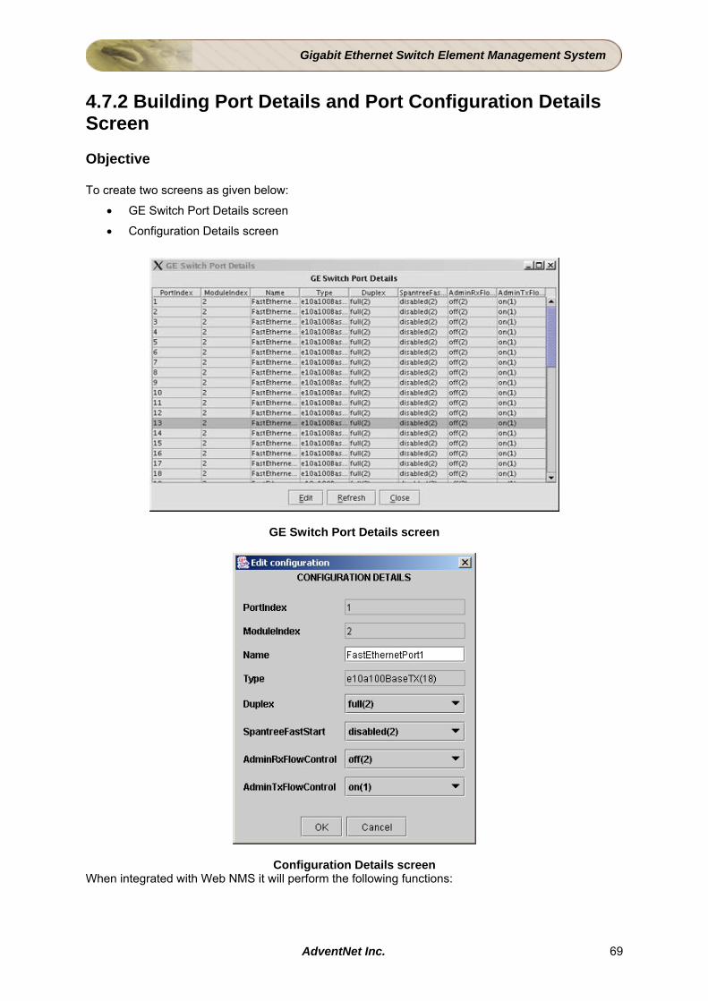
Gigabit Ethernet Switch Element Management System
4.7.2 Building Port Details and Port Configuration Details Screen Objective To create two screens as given below:
• GE Switch Port Details screen
• Configuration Details screen
GE Switch Port Details screen
Configuration Details screen When integrated with Web NMS it will perform the following functions:
AdventNet Inc. 69
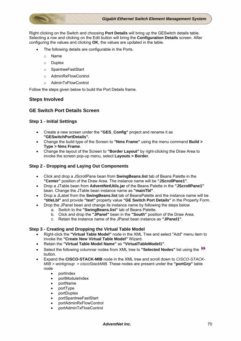
Gigabit Ethernet Switch Element Management System
Right clicking on the Switch and choosing Port Details will bring up the GESwitch details table. Selecting a row and clicking on the Edit button will bring the Configuration Details screen. After configuring the values and clicking OK, the values are updated in the table.
• The following details are configurable in the Ports. o Name o Duplex o SpantreeFastStart o AdminRxFlowControl o AdminTxFlowControl
Follow the steps given below to build the Port Details frame. Steps Involved GE Switch Port Details Screen Step 1 - Initial Settings
• Create a new screen under the "GES_Config" project and rename it as "GESwitchPortDetails".
• Change the build type of the Screen to "Nms Frame" using the menu command Build > Type > Nms Frame.
• Change the layout of the Screen to "Border Layout" by right-clicking the Draw Area to invoke the screen pop-up menu, select Layouts > Border.
Step 2 - Dropping and Laying Out Components
• Click and drop a JScrollPane bean from SwingBeans.list tab of Beans Palette in the "Center" position of the Draw Area. The instance name will be "JScrollPane1".
• Drop a JTable bean from AdventNetUtils.jar of the Beans Palette in the "JScrollPane1" bean. Change the JTable bean instance name as "mainTbl".
• Drop a JLabel from the SwingBeans.list tab of BeansPalette and the instance name will be "titleLbl" and provide "text" property value "GE Switch Port Details" in the Property Form.
• Drop the JPanel bean and change its instance name by following the steps below a. Switch to the "SwingBeans.list" tab of Beans Palette. b. Click and drop the "JPanel" bean in the "South" position of the Draw Area. c. Retain the instance name of the JPanel bean instance as "JPanel1".
Step 3 - Creating and Dropping the Virtual Table Model
• Right-click the "Virtual Table Model" node in the XML Tree and select "Add" menu item to invoke the "Create New Virtual Table Model" Wizard.
• Retain the "Virtual Table Model Name" as "VirtualTableModel1". • Select the following columnar nodes from XML tree to "Selected Nodes" list using the
button. • Expand the CISCO-STACK-MIB node in the XML tree and scroll down to CISCO-STACK-
MIB > workgroup > ciscoStackMIB. These nodes are present under the "portGrp" table node
• portIndex • portModuleIndex • portName • portType • portDuplex • portSpantreeFastStart • portAdminRxFlowControl • portAdminTxFlowControl
AdventNet Inc. 70
Gigabit Ethernet Switch Element Management System
• Click "Next" button to proceed to final screen of the Wizard. • Click "Finish" button to close the Virtual Table Model Wizard. • Click the "VirtualTableModel1" node under the "Virtual Table Model" node of the XML tree
and drop outside the Draw Area. You can find the name of dropped bean is "VirtualTableModel11" .
• Double-click the "mainTbl" to invoke the Property Form. Select the "model" and choose the "PortParmetersTable11" from the combo box.
• Add the following code under the package import declarations as given below : import com.adventnet.beans.configuration.GroupInfoCache;
Step 4 - Creating Config Group
• Switch to the Config tab. You will see default group created with the name group1. • Select the "portNameInstance" node from the XML Tree, and click the "Add Attribute"
button to add the attributes from the Xml Tree to the Config Tree. • Edit the code in the "Code Area" and the following code Properties valueProp = new Properties(); valueProp.setProperty(LABEL,"portNameInstance"); valueProp.setProperty(TYPE,"4"); valueProp.setProperty(VALUE, String.valueOf(portNameInstance_comp.getText())); return valueProp;
• Select the "portDuplexInstance" node from the XML Tree, and click the "Add Attribute"
button to add the attributes from the Xml Tree to the Config Tree. • Edit the code in the "Code Area" and the following code Properties valueProp = new Properties(); valueProp.setProperty(LABEL,"portDuplexInstance"); valueProp.setProperty(TYPE,"2"); valueProp.setProperty(VALUE, String.valueOf(new Integer(portDuplexInstance_comp.getSelectedIndex()+1))); return valueProp;
• Select the "portSpantreeFastStartInstance" node from the XML Tree, and click the "Add
Attribute" button to add the attributes from the Xml Tree to the Config Tree. • Edit the code in the "Code Area" and the following code Properties valueProp = new Properties(); valueProp.setProperty(LABEL,"portSpantreeFastStartInstance"); valueProp.setProperty(TYPE,"2"); valueProp.setProperty(VALUE, String.valueOf(new Integer(portSpantreeFastStartInstance_comp.getSelectedIndex()+1))); return valueProp;
• Select the "portAdminRxFlowControlInstance" node from the XML Tree, and click the
"Add Attribute" button to add the attributes from the Xml Tree to the Config Tree. • Edit the code in the "Code Area" and the following code Properties valueProp = new Properties(); valueProp.setProperty(LABEL,"portAdminRxFlowControlInstance"); valueProp.setProperty(TYPE,"2");
AdventNet Inc. 71
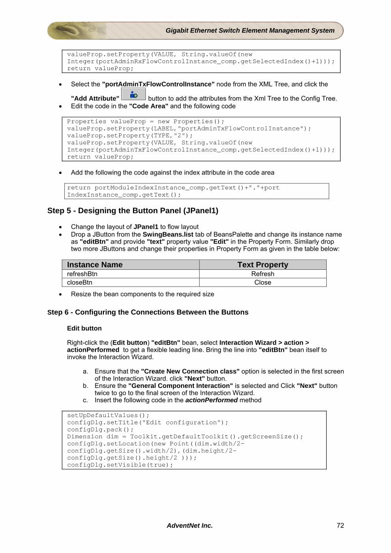
Gigabit Ethernet Switch Element Management System
valueProp.setProperty(VALUE, String.valueOf(new Integer(portAdminRxFlowControlInstance_comp.getSelectedIndex()+1))); return valueProp;
• Select the "portAdminTxFlowControlInstance" node from the XML Tree, and click the
"Add Attribute" button to add the attributes from the Xml Tree to the Config Tree. • Edit the code in the "Code Area" and the following code Properties valueProp = new Properties(); valueProp.setProperty(LABEL,"portAdminTxFlowControlInstance"); valueProp.setProperty(TYPE,"2"); valueProp.setProperty(VALUE, String.valueOf(new Integer(portAdminTxFlowControlInstance_comp.getSelectedIndex()+1))); return valueProp;
• Add the following the code against the index attribute in the code area return portModuleIndexInstance_comp.getText()+"."+port IndexInstance_comp.getText();
Step 5 - Designing the Button Panel (JPanel1)
• Change the layout of JPanel1 to flow layout • Drop a JButton from the SwingBeans.list tab of BeansPalette and change its instance name
as "editBtn" and provide "text" property value "Edit" in the Property Form. Similarly drop two more JButtons and change their properties in Property Form as given in the table below:
Instance Name Text Property refreshBtn Refresh closeBtn Close
• Resize the bean components to the required size
Step 6 - Configuring the Connections Between the Buttons
Edit button Right-click the (Edit button) "editBtn" bean, select Interaction Wizard > action > actionPerformed to get a flexible leading line. Bring the line into "editBtn" bean itself to invoke the Interaction Wizard.
a. Ensure that the "Create New Connection class" option is selected in the first screen of the Interaction Wizard. click "Next" button.
b. Ensure the "General Component Interaction" is selected and Click "Next" button twice to go to the final screen of the Interaction Wizard.
c. Insert the following code in the actionPerformed method
setUpDefaultValues(); configDlg.setTitle("Edit configuration"); configDlg.pack(); Dimension dim = Toolkit.getDefaultToolkit().getScreenSize(); configDlg.setLocation(new Point((dim.width/2-configDlg.getSize().width/2),(dim.height/2-configDlg.getSize().height/2 ))); configDlg.setVisible(true);
AdventNet Inc. 72
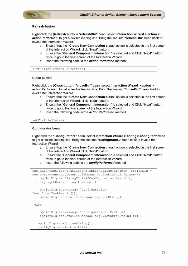
Gigabit Ethernet Switch Element Management System
Refresh button
Right-click the (Refresh button) "refreshBtn" bean, select Interaction Wizard > action > actionPerformed to get a flexible leading line. Bring the line into "refreshBtn" bean itself to invoke the Interaction Wizard.
a. Ensure that the "Create New Connection class" option is selected in the first screen of the Interaction Wizard. click "Next" button.
b. Ensure the "General Component Interaction" is selected and Click "Next" button twice to go to the final screen of the Interaction Wizard.
c. Insert the following code in the actionPerformed method
VirtualTableModel31.refresh();
Close button
Right-click the (Close button) "closeBtn" bean, select Interaction Wizard > action > actionPerformed to get a flexible leading line. Bring the line into "closeBtn" bean itself to invoke the Interaction Wizard.
a. Ensure that the "Create New Connection class" option is selected in the first screen of the Interaction Wizard. click "Next" button.
b. Ensure the "General Component Interaction" is selected and Click "Next" button twice to go to the final screen of the Interaction Wizard.
c. Insert the following code in the actionPerformed method
setVisible(false);
Configurator bean
Right-click the "Configurator1" bean, select Interaction Wizard > config > configPerformed to get a flexible leading line. Bring the line into "Configurator1" bean itself to invoke the Interaction Wizard.
a. Ensure that the "Create New Connection class" option is selected in the first screen of the Interaction Wizard. click "Next" button.
b. Ensure the "General Component Interaction" is selected and Click "Next" button twice to go to the final screen of the Interaction Wizard.
c. Insert the following code in the configPerformed method
com.adventnet.beans.utilbeans.OptionDialogInformer optionDlg = new com.adventnet.beans.utilbeans.OptionDialogInformer(); optionDlg.setDialogTitle("Configuration Result"); if(arg0.getErrorString() == null) { optionDlg.setMessage("Configuration: "+arg0.getTaskResult()); optionDlg.setDetailedMessage(arg0.toString()); } else { optionDlg.setMessage("Configuration: Failure"); optionDlg.setDetailedMessage(arg0.getErrorString()); } optionDlg.showOptionDialog(); configDlg.setVisible(false);
AdventNet Inc. 73

Gigabit Ethernet Switch Element Management System
Configuration Details Screen (pop-up) Drop the JPanel bean and change its instance name by following the steps below
a. Switch to the "SwingBeans.list" tab of Beans Palette. b. Click and drop the "JPanel" bean outside the Draw Area. . c. Change the instance name of the JPanel bean instance as "addEditPanel".
Step 1 - Initial Settings
• Drop a JLabel from the SwingBeans.list tab of BeansPalette and the instance name will be "titleLbl" and provide "text" property value "Configuration Details" in the Property Form.
• Drop the JPanel bean and change its instance name by following the steps below a. Switch to the "SwingBeans.list" tab of Beans Palette. b. Click and drop the "JPanel" bean in the "Center" position of the Draw Area. c. Retain the instance name of the JPanel bean instance as "JPanel1".
• Drop the JPanel bean and change its instance name by following the steps below a. Switch to the "SwingBeans.list" tab of Beans Palette. b. Click and drop the "JPanel" bean in the "South" position of the Draw Area. c. Retain the instance name of the JPanel bean instance as "JPanel2".
Step 2 - Dropping and Laying Out Components
• Drop a JLabel from the SwingBeans.list tab of BeansPalette and the instance name will be "JLabel1" and provide "text" property value "PortIndex" in the Property Form. Change the instance name of the JLabel bean instance as "portIndexInstance_lbl". Similarly drop seven more JLabels and change their properties in Property Form as given in the table below
Instance Name Change Instance Name Text Property
JLabel2 portModuleIndexInstance_lbl ModuleIndex JLabel3 portNameInstance_lbl Name JLabel4 portTypeInstance_lbl Type JLabel5 portDuplexInstance_lbl Duplex JLabel6 portSpantreeFastStartInstance_lbl SpantreeFastStart JLabel7 portAdminRxFlowControlInstance_lbl AdminRxFlowControl JLabel8 portAdminTxFlowControlInstance_lbl AdminTxFlowControl
Step 3 - Customizing the Layout
• Invoke the "GridBag Layout Customizer" window for the "JPanel1" by right-clicking the screen and select "Layout Properties".
• In the GridBag Layout Customizer, set the properties for all the components. Step 4 - Designing the Button Panel (JPanel2)
• Change the layout of JPanel2 to flow layout • Drop a JButton from the SwingBeans.list tab of BeansPalette and change its instance name
as "okbtn" and provide "text" property value "OK" in the Property Form. • Drop a JButton from the SwingBeans.list tab of BeansPalette and change its instance name
as "cancelBtn" and provide "text" property value "Cancel" in the Property Form. • Resize the bean components to the required size
AdventNet Inc. 74
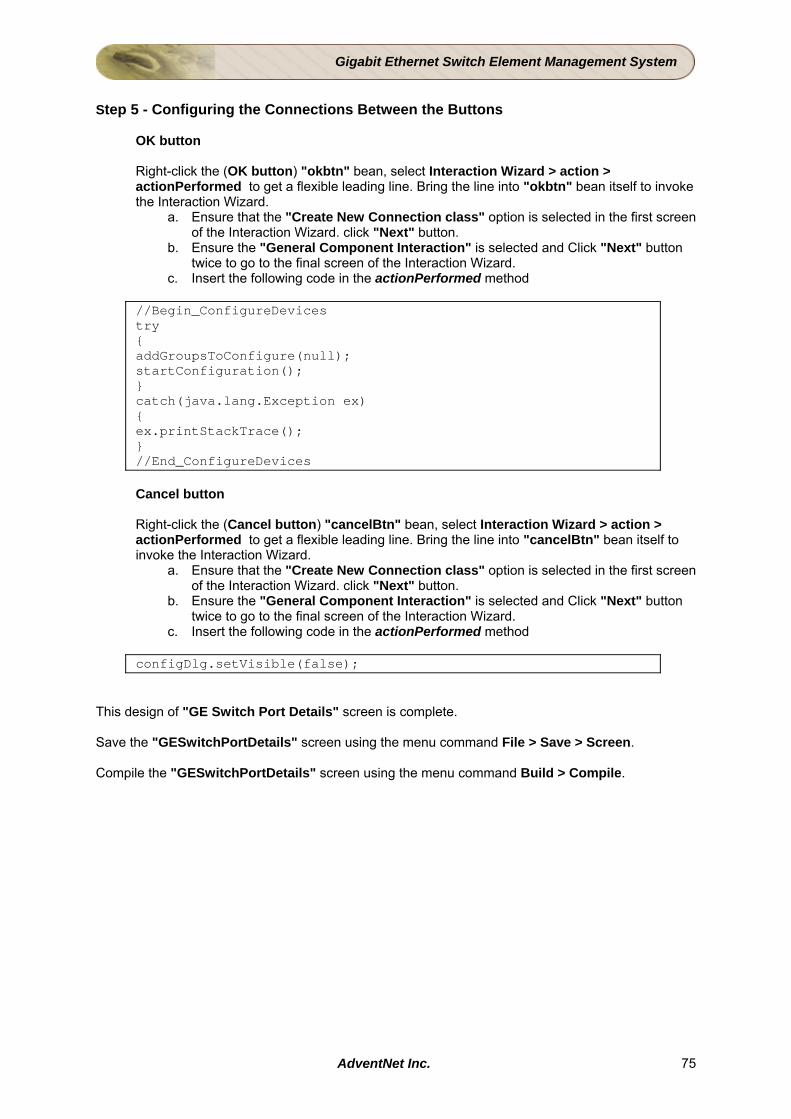
Gigabit Ethernet Switch Element Management System
Step 5 - Configuring the Connections Between the Buttons
OK button
Right-click the (OK button) "okbtn" bean, select Interaction Wizard > action > actionPerformed to get a flexible leading line. Bring the line into "okbtn" bean itself to invoke the Interaction Wizard.
a. Ensure that the "Create New Connection class" option is selected in the first screen of the Interaction Wizard. click "Next" button.
b. Ensure the "General Component Interaction" is selected and Click "Next" button twice to go to the final screen of the Interaction Wizard.
c. Insert the following code in the actionPerformed method
//Begin_ConfigureDevices try { addGroupsToConfigure(null); startConfiguration(); } catch(java.lang.Exception ex) { ex.printStackTrace(); } //End_ConfigureDevices Cancel button
Right-click the (Cancel button) "cancelBtn" bean, select Interaction Wizard > action > actionPerformed to get a flexible leading line. Bring the line into "cancelBtn" bean itself to invoke the Interaction Wizard.
a. Ensure that the "Create New Connection class" option is selected in the first screen of the Interaction Wizard. click "Next" button.
b. Ensure the "General Component Interaction" is selected and Click "Next" button twice to go to the final screen of the Interaction Wizard.
c. Insert the following code in the actionPerformed method
configDlg.setVisible(false); This design of "GE Switch Port Details" screen is complete. Save the "GESwitchPortDetails" screen using the menu command File > Save > Screen. Compile the "GESwitchPortDetails" screen using the menu command Build > Compile.
AdventNet Inc. 75
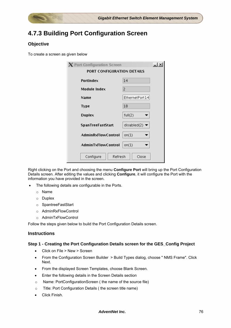
Gigabit Ethernet Switch Element Management System
4.7.3 Building Port Configuration Screen Objective To create a screen as given below
Right clicking on the Port and choosing the menu Configure Port will bring up the Port Configuration Details screen. After editing the values and clicking Configure, it will configure the Port with the information you have provided in the screen.
• The following details are configurable in the Ports. o Name o Duplex o SpantreeFastStart o AdminRxFlowControl o AdminTxFlowControl
Follow the steps given below to build the Port Configuration Details screen. Instructions Step 1 - Creating the Port Configuration Details screen for the GES_Config Project
• Click on File > New > Screen
• From the Configuration Screen Builder > Build Types dialog, choose " NMS Frame". Click Next.
• From the displayed Screen Templates, choose Blank Screen.
• Enter the following details in the Screen Details section o Name: PortConfigurationScreen ( the name of the source file) o Title: Port Configuration Details ( the screen title name)
• Click Finish.
AdventNet Inc. 76
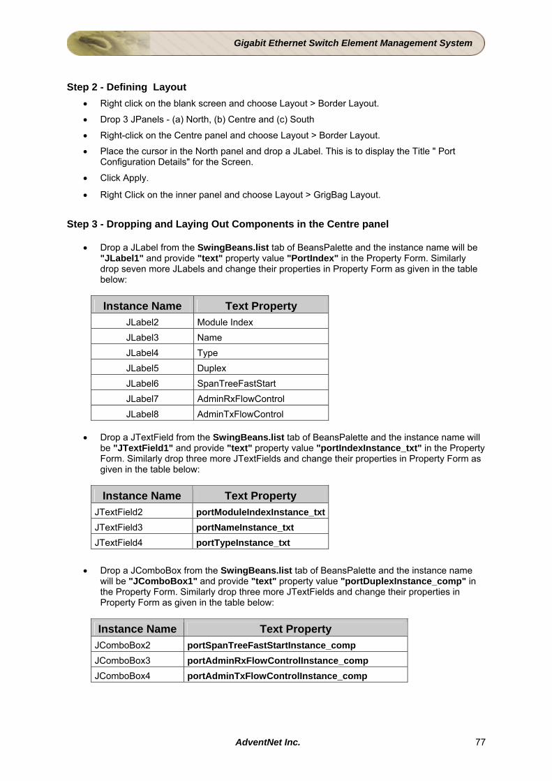
Gigabit Ethernet Switch Element Management System
Step 2 - Defining Layout
• Right click on the blank screen and choose Layout > Border Layout.
• Drop 3 JPanels - (a) North, (b) Centre and (c) South
• Right-click on the Centre panel and choose Layout > Border Layout.
• Place the cursor in the North panel and drop a JLabel. This is to display the Title " Port Configuration Details" for the Screen.
• Click Apply.
• Right Click on the inner panel and choose Layout > GrigBag Layout.
Step 3 - Dropping and Laying Out Components in the Centre panel
• Drop a JLabel from the SwingBeans.list tab of BeansPalette and the instance name will be "JLabel1" and provide "text" property value "PortIndex" in the Property Form. Similarly drop seven more JLabels and change their properties in Property Form as given in the table below:
Instance Name Text Property JLabel2 Module Index JLabel3 Name JLabel4 Type JLabel5 Duplex JLabel6 SpanTreeFastStart JLabel7 AdminRxFlowControl JLabel8 AdminTxFlowControl
• Drop a JTextField from the SwingBeans.list tab of BeansPalette and the instance name will
be "JTextField1" and provide "text" property value "portIndexInstance_txt" in the Property Form. Similarly drop three more JTextFields and change their properties in Property Form as given in the table below:
Instance Name Text Property JTextField2 portModuleIndexInstance_txtJTextField3 portNameInstance_txt JTextField4 portTypeInstance_txt
• Drop a JComboBox from the SwingBeans.list tab of BeansPalette and the instance name
will be "JComboBox1" and provide "text" property value "portDuplexInstance_comp" in the Property Form. Similarly drop three more JTextFields and change their properties in Property Form as given in the table below:
Instance Name Text Property JComboBox2 portSpanTreeFastStartInstance_comp JComboBox3 portAdminRxFlowControlInstance_comp JComboBox4 portAdminTxFlowControlInstance_comp
AdventNet Inc. 77
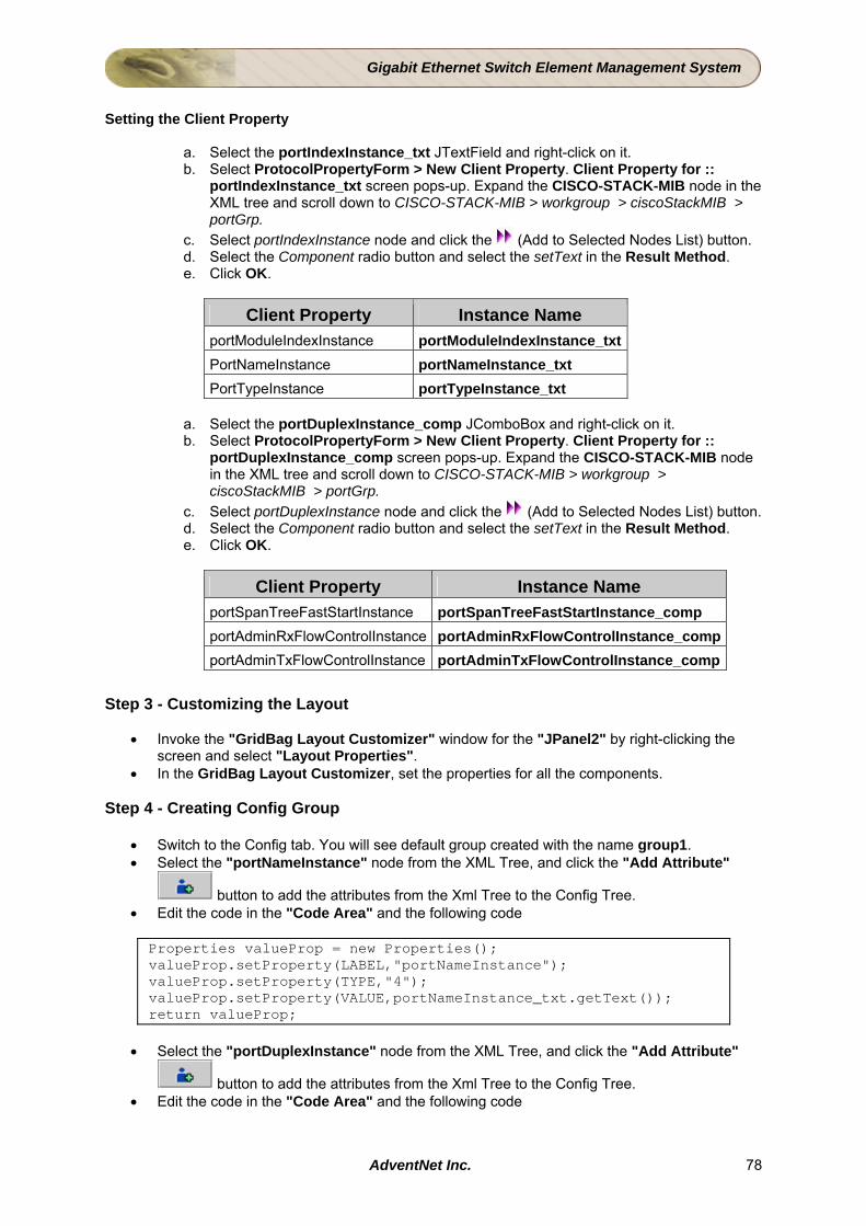
Gigabit Ethernet Switch Element Management System
Setting the Client Property
a. Select the portIndexInstance_txt JTextField and right-click on it. b. Select ProtocolPropertyForm > New Client Property. Client Property for ::
portIndexInstance_txt screen pops-up. Expand the CISCO-STACK-MIB node in the XML tree and scroll down to CISCO-STACK-MIB > workgroup > ciscoStackMIB > portGrp.
c. Select portIndexInstance node and click the (Add to Selected Nodes List) button. d. Select the Component radio button and select the setText in the Result Method. e. Click OK.
Client Property Instance Name portModuleIndexInstance portModuleIndexInstance_txt PortNameInstance portNameInstance_txt PortTypeInstance portTypeInstance_txt
a. Select the portDuplexInstance_comp JComboBox and right-click on it. b. Select ProtocolPropertyForm > New Client Property. Client Property for ::
portDuplexInstance_comp screen pops-up. Expand the CISCO-STACK-MIB node in the XML tree and scroll down to CISCO-STACK-MIB > workgroup > ciscoStackMIB > portGrp.
c. Select portDuplexInstance node and click the (Add to Selected Nodes List) button. d. Select the Component radio button and select the setText in the Result Method. e. Click OK.
Client Property Instance Name portSpanTreeFastStartInstance portSpanTreeFastStartInstance_comp portAdminRxFlowControlInstance portAdminRxFlowControlInstance_compportAdminTxFlowControlInstance portAdminTxFlowControlInstance_comp
Step 3 - Customizing the Layout
• Invoke the "GridBag Layout Customizer" window for the "JPanel2" by right-clicking the screen and select "Layout Properties".
• In the GridBag Layout Customizer, set the properties for all the components. Step 4 - Creating Config Group
• Switch to the Config tab. You will see default group created with the name group1. • Select the "portNameInstance" node from the XML Tree, and click the "Add Attribute"
button to add the attributes from the Xml Tree to the Config Tree. • Edit the code in the "Code Area" and the following code
Properties valueProp = new Properties(); valueProp.setProperty(LABEL,"portNameInstance"); valueProp.setProperty(TYPE,"4"); valueProp.setProperty(VALUE,portNameInstance_txt.getText()); return valueProp;
• Select the "portDuplexInstance" node from the XML Tree, and click the "Add Attribute"
button to add the attributes from the Xml Tree to the Config Tree. • Edit the code in the "Code Area" and the following code
AdventNet Inc. 78
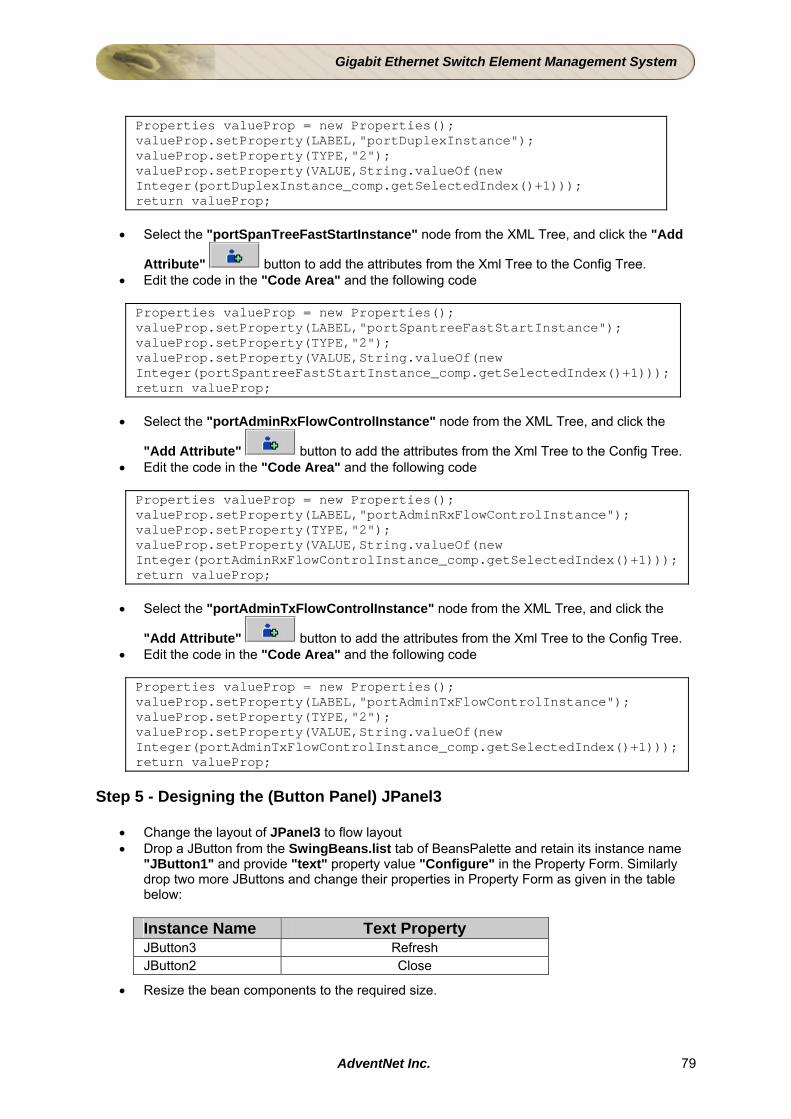
Gigabit Ethernet Switch Element Management System
Properties valueProp = new Properties(); valueProp.setProperty(LABEL,"portDuplexInstance"); valueProp.setProperty(TYPE,"2"); valueProp.setProperty(VALUE,String.valueOf(new Integer(portDuplexInstance_comp.getSelectedIndex()+1))); return valueProp;
• Select the "portSpanTreeFastStartInstance" node from the XML Tree, and click the "Add
Attribute" button to add the attributes from the Xml Tree to the Config Tree. • Edit the code in the "Code Area" and the following code
Properties valueProp = new Properties(); valueProp.setProperty(LABEL,"portSpantreeFastStartInstance"); valueProp.setProperty(TYPE,"2"); valueProp.setProperty(VALUE,String.valueOf(new Integer(portSpantreeFastStartInstance_comp.getSelectedIndex()+1))); return valueProp;
• Select the "portAdminRxFlowControlInstance" node from the XML Tree, and click the
"Add Attribute" button to add the attributes from the Xml Tree to the Config Tree. • Edit the code in the "Code Area" and the following code
Properties valueProp = new Properties(); valueProp.setProperty(LABEL,"portAdminRxFlowControlInstance"); valueProp.setProperty(TYPE,"2"); valueProp.setProperty(VALUE,String.valueOf(new Integer(portAdminRxFlowControlInstance_comp.getSelectedIndex()+1))); return valueProp;
• Select the "portAdminTxFlowControlInstance" node from the XML Tree, and click the
"Add Attribute" button to add the attributes from the Xml Tree to the Config Tree. • Edit the code in the "Code Area" and the following code
Properties valueProp = new Properties(); valueProp.setProperty(LABEL,"portAdminTxFlowControlInstance"); valueProp.setProperty(TYPE,"2"); valueProp.setProperty(VALUE,String.valueOf(new Integer(portAdminTxFlowControlInstance_comp.getSelectedIndex()+1))); return valueProp;
Step 5 - Designing the (Button Panel) JPanel3
• Change the layout of JPanel3 to flow layout • Drop a JButton from the SwingBeans.list tab of BeansPalette and retain its instance name
"JButton1" and provide "text" property value "Configure" in the Property Form. Similarly drop two more JButtons and change their properties in Property Form as given in the table below:
Instance Name Text Property JButton3 Refresh JButton2 Close
• Resize the bean components to the required size.
AdventNet Inc. 79
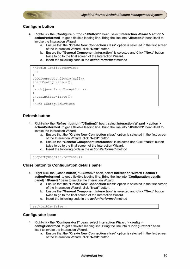
Gigabit Ethernet Switch Element Management System
Configure button
4. Right-click the (Configure button) "JButton1" bean, select Interaction Wizard > action > actionPerformed to get a flexible leading line. Bring the line into "JButton1" bean itself to invoke the Interaction Wizard.
a. Ensure that the "Create New Connection class" option is selected in the first screen of the Interaction Wizard. click "Next" button.
b. Ensure the "General Component Interaction" is selected and Click "Next" button twice to go to the final screen of the Interaction Wizard.
c. Insert the following code in the actionPerformed method
//Begin_ConfigureDevices try { addGroupsToConfigure(null); startConfiguration(); } catch(java.lang.Exception ex) { ex.printStackTrace(); } //End_ConfigureDevices
Refresh button
4. Right-click the (Refresh button) "JButton3" bean, select Interaction Wizard > action > actionPerformed to get a flexible leading line. Bring the line into "JButton3" bean itself to invoke the Interaction Wizard.
a. Ensure that the "Create New Connection class" option is selected in the first screen of the Interaction Wizard. click "Next" button.
b. Ensure the "General Component Interaction" is selected and Click "Next" button twice to go to the final screen of the Interaction Wizard.
c. Insert the following code in the actionPerformed method
propertyHandler.refresh(); Close button to Configuration details panel
4. Right-click the (Close button) "JButton2" bean, select Interaction Wizard > action > actionPerformed to get a flexible leading line. Bring the line into (Configuration details panel) "JPanel2" bean to invoke the Interaction Wizard.
a. Ensure that the "Create New Connection class" option is selected in the first screen of the Interaction Wizard. click "Next" button.
b. Ensure the "General Component Interaction" is selected and Click "Next" button twice to go to the final screen of the Interaction Wizard.
c. Insert the following code in the actionPerformed method
setVisible(false); Configurator bean
4. Right-click the "Configurator1" bean, select Interaction Wizard > config > configPerformed to get a flexible leading line. Bring the line into "Configurator1" bean itself to invoke the Interaction Wizard.
a. Ensure that the "Create New Connection class" option is selected in the first screen of the Interaction Wizard. click "Next" button.
AdventNet Inc. 80
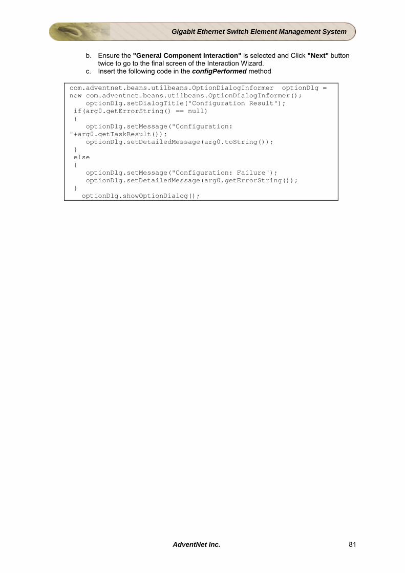
Gigabit Ethernet Switch Element Management System
b. Ensure the "General Component Interaction" is selected and Click "Next" button
twice to go to the final screen of the Interaction Wizard. c. Insert the following code in the configPerformed method
com.adventnet.beans.utilbeans.OptionDialogInformer optionDlg = new com.adventnet.beans.utilbeans.OptionDialogInformer(); optionDlg.setDialogTitle("Configuration Result"); if(arg0.getErrorString() == null) { optionDlg.setMessage("Configuration: "+arg0.getTaskResult()); optionDlg.setDetailedMessage(arg0.toString()); } else { optionDlg.setMessage("Configuration: Failure"); optionDlg.setDetailedMessage(arg0.getErrorString()); } optionDlg.showOptionDialog();
AdventNet Inc. 81
Gigabit Ethernet Switch Element Management System
4.7.4 Packaging the Configuration Screens The screens built using the Configuration Wizard, have to be imported to the Studio Project. The Packager Wizard in the configuration Wizard, bundles all the screens to form a NAR (NMS ARchive). After the NAR is created, the NAR is imported into Web NMS Studio (using Import NAR Wizard). Follow the steps given below to package and import the NAR into Studio Project. Packaging the Project
• Select Tools > Package for Web NMS > Device Specific.
• Select “com.adventnet.nms.tutorials.ges.GESwitchConfiguration” from the “Main Class Information” screen. Click Next to proceed to next screen.
• In the “General Information”, without doing anything, Click Next to proceed to next screen.
• Specify the device type as “GESwitch”.
• In the “Resources to Install” screen, add the image geswitch_config.jpg under <Client Builder Home>/images. Click Next to proceed to next screen.
• Select the "HOST" value from the Parameter list and provide the value "${name}" in the "Value" text field. Click Modify to change the values in the list.
• Similarly, select the "PORT" parameter from the Parameter list. Change the value to "${snmpport}".
• Click Finish to close the Packager Wizard.
Integrating the Configuration NAR into Studio • Select Tools > Import Nar from the menu bar of Web NMS Studio Wizard.
• Select GESwitchConfiguration.nar under <Web NMS Home>/StudioTools/ClientBuilder directory or where the NAR was created. Click Next to proceed to next screen.
• Select “root” in the User Information screen and click Next to proceed to next screen.
• In the “Map Menu Information” screen, select “Configure Map Menu”.
• Provide “Menu Name” as “snmpmenu”, “Menu Item Name” as “Configure Device” and “Image for the Map” as “switch.png”. Click Next to proceed to next screen.
• We will be associating the list menus. In the “List Menu Information” screen, select “Configure List Menu”.
• Provide “Menu Name” as “snmpmenu”, “Menu Item Name” as “Configure Device”. Click Next to proceed to next screen.
• Click Finish to close the Import NAR Wizard.
AdventNet Inc. 82
Gigabit Ethernet Switch Element Management System
4.8 Rebranding In building your EMS, you may wish to customize the basic user interface functions. Web NMS supports such customization for creating new products in multiple ways. To illustrate how this can be done, you will make a few changes to the user interface to build an EMS that we will call as GES EMS. These are only a subset of the many changes that can be made to the user interface for specific applications. Aim This section details on how to Rebrand the application built to suit the customers requirements. Rebranding includes changing the name of the product its version, splash images, logo images etc. Rebranding can be achieved using the Rebranding tool. For details on Rebranding the Project, refer to the Web NMS Studio Help documentation. Instructions Follow the steps given below to Rebrand the EMS.
Step: Invoke the Rebranding tool from Tools menu Changing the Company details, Product details, Icons, and Images
• Select Tools > Rebranding from the menu bar to invoke the Rebranding tool. • Change the values of the rebrandable entities as given in the table below:
Entity Name Values Company Name AdventNet
Product Name GE Switch EMS
Version 1.0 Company URL www.adventnet.com
Motto AdventNet : Excellence Matters Copyright Copyright 2004
Splash Image
<Web NMS Home>/StudioTools/Studio/projects/GES_Tutorial/WebNMS//images/progressimage.png
Frame Icon <Web NMS Home>/StudioTools/Studio/projects/GES_Tutorial/WebNMS/images/adventneticon.jpg
Product Logo
<Web NMS Home>/StudioTools/Studio/projects/GES_Tutorial/WebNMS/images/logoPane.png
About Dialog Image
Select the image file of your choice
Contact Address Enter the contact address of your company
Language En Country US
• Click on Rebrand button to carryout Rebranding and the Close button to close the
screen.
AdventNet Inc. 83

Gigabit Ethernet Switch Element Management System
Result The AdventNet Web NMS is rebranded as GES EMS. The final step towards creating EMS follows next - Packaging and Installation.
AdventNet Inc. 84
Gigabit Ethernet Switch Element Management System
4.9 Packaging GES EMS Project This topic explains the process of compiling and packaging the Studio project.
• Compile the Project • Package the Application
Compile the Project After building the project, save it, and compile it.
• Select the File > Save Project menu from the Studio. • Select the Project > Compile menu from the Studio.
Package the Application After compiling the project, package the application into a NAR file. For details of Packaging Studio Applications of AdventNet Web NMS Studio, refer to the AdventNet Web NMS Studio documentation.
• Select the Project > Package menu from the Studio. Package Wizard comes up and carry out the packaging in 8 steps.
1. Project and NAR Details - Enter the Nar File Name as GES_Tutorial1.0.nar, Destination Directory, and README File Name and click Next button.
2. Select Services - Select the Services you have configured so far in the project and click Next button.
3. Database Details - Select the database. Enter the database details URL, Driver Name, User Name, Password, Trans-Connection, and Non Trans-Connection and click Next button.
4. Map and List Icons - Select the Map Icon to represent the type of device (switch, printer etc).This project uses pc.png located in <Web NMS Home>images directory to represent a node. Select List Icons to represent severity of the device and click Next button. The icons for this project are selected from <Web NMS Home>icons directory. Note that, if you enable the Transparent option, you can just choose one icon and the severity will be rendered automatically.
5. Other Resources - Select the menus and images needed to bundled in the NAR.
File Name Location GEModuleHtmlLayout.class GEModuleHtmlRenderer.class GEPortHtmlLayout.class GEPortHtmlRenderer.class GESwitchHtmlLayout.class GESwitchHtmlRenderer.class
Resource Path: <Project Home>/classes/client/com/adventnet/nms/tutorials/ges/ Target Directory : ./WEB-INF/classes/com/adventnet/nms/tutorials/ges/
ethernetmodule.png geport-down.png geport-up.png ges.png geswitch.png port-down.png port-up.png
Resource Path: <Project Home>/WebNMS/images/ Target Directory : ./webclient/map/images/
AdventNet Inc. 85
Gigabit Ethernet Switch Element Management System
File Name Location
supervisormodule.png switch.png
web.xml Resource Path: <Project Home>/WebNMS/WEB-INF/ Target Directory : ./WEB-INF/
mapwebclientconfig.xml Resource Path: <Project Home>/WebNMS/webclient/map/conf/ Target Directory : ./webclient/map/conf/
In the Resource Path, select the <File Name> and in the Target Directory enter Location. Click Add button. Using the same procedure add all the files and click Next button.
6. Additional JAR - Add the following additional JAR required and click Next button.
Jars List Location <TOOL HOME>/jars/StudioUtils.jar Target Directory : NetMonitor/build/
Update Classpath In .. : server
7. Client NARs - Ensure that the required Client NAR (GESwitchConfiguration.nar) imported using Import NAR Wizard is selected for package and click Next button.
8. Create NAR - In this project, we have selected Complete Packaging so that files pertaining to all Services are packaged. Select Selective Packaging option to package the files for the selected Services only. This will package the dependent files (conf files, classes, jars etc.) also using certain algorithm. Click Finish.
This will generate a NAR file called GES_Tutorial1.0.nar. You can deploy this NAR directly into Web NMS to install the application.
Note: While packaging GES Tutorial from Studio, webclient-map.jar and jgraphs.jar should be removed and then packaged.
AdventNet Inc. 86
Gigabit Ethernet Switch Element Management System
5 Installation and Testing 5.1 Installing the Application Aim To install the packaged NAR in Web NMS using Deployment Wizard Instructions
Step 1: Invoking Deployment Wizard
Start the Deployment wizard by invoking DeploymentWizard.sh/bat file from <Web NMS Home>/bin/ directory. The Deployment Wizard appears.
Step 2: Selecting the NAR
• Switch to NarInstall/Unistall tab.
• Click Install to invoke the NAR INSTALLER window.
• Click Browse to invoke the file chooser and select the GES_Tutorial1.0.nar from the location where you have packaged and click Select.
• Click OK to close the NAR INSTALLER window. This invokes PWSNarInstaller Wizard.
Step 3: Installing the NAR • Read the README provided with NAR. MySQL Database is chosen by default.
• Click Next button.
• Select Install to install the NAR. After the NAR is installed click Close.
• Close the Deployment tool using Exit.
AdventNet Inc. 87

Gigabit Ethernet Switch Element Management System
5.2 Installation and Testing After installing GES tutorial NAR in Web NMS, set the testing environment as mentioned below. Once discovery process is complete, view the GE switch discovered under the GESwitch map of client. Setting Up Environment for Testing Follow the steps given below for test setup for testing the GES tutorial application
Starting Agent
Configuration files for the GES agent simulator is bundled in the Client Builder under <Web NMS Home>/StudioTools/ClientBuilder/projects/GESConfig/Agent directory.
To start the GE switch agent, follow the steps below.
1. Invoke SNMP Agent Simulator using startSNMPAgentSimulator.bat/sh present under <Web NMS Home>/StudioTools/ClientBuilder/bin or using Web NMS Launcher.
2. Load the agent configuration file agent_main.xml present under <Web NMS Home>/tutorials/ges_tutorial/agent_simulator directory.
3. Change the Port in which agent to be started using Agent Settings dialog. Invoke the Agent Settings dialog using menu command Settings > Agent Settings. Change Port to "8002" and click OK.
4. Start the agent using menu command Operations > Start Agent.
Sending Traps 1. From Settings menu, choose Trap Settings. The Trap Settings dialog box is
displayed.
2. Specify the IP address of the agent is running in Agent Address field.
3. Invoke Trap Configurations dialog using menu command Configure > Traps.
4. Select the row present in the dialog box.
5. Click Modify. The Configure Traps dialog box is displayed.
6. Specify the IP address where the Web NMS server is running in Manager Name. Specify the port where Web NMS server is running in Manager Port field.
7. Click Ok.
8. Click Send.
Configure the seed.file
To discover the GE switch devices, which is simulated at the port defined in agent simulator, Web NMS provides seed.file in <Web NMS Home>/conf directory which allows you to configure the devices and networks to be discovered at different ports.
• Use the Discovery Configurator tool to configure SNMP devices in the seed.file.
• Invoke the tool by running the DiscoveryConfigurator.bat/sh file present in the <Web NMS Home>/bin directory. Select the SNMP Devices.
AdventNet Inc. 88
Gigabit Ethernet Switch Element Management System
• Enter the IP Address and Port of the Agent. For using the Discovery Configurator
tool, refer to the Configuring Discovery of SNMP Devices topic in Administrator Guide.
This tutorial discovers all the SNMP Devices configured in the seed.file first and also discovers the various modules and ports installed in the Switch.
Alternate Configuration of seed.file
• Copy the following into the seed.file.
<TO_DISCOVERIP> <ip NODE_ID="" NETMASK="" COMMUNITY="public" SNMPAGENTPORT=""/> <ip NODE_ID="" NETMASK="" COMMUNITY="public" SNMPAGENTPORT=""/> </TO_DISCOVERIP>
• Before the </SEED> tag.
• Enter the NODE_ID values as the IP Address of the machines in which the GE switch agents are running, set the value of SNMPAGENTPORT as 8002, retain the value of COMMUNITY as public and set the NETMASK values accordingly.
• Save the seed.file.
Testing Output in Web NMS
Start NMS • Before starting the Web NMS server, you have to set agent. Refer Setting up
Environment for Testing for details.
• Start the Web NMS Launcher, by invoking WebNMSLauncher.bat/.sh file in the <Web NMS HOME> directory.
• Click Start NMS Server icon in the Web NMS Launcher.
Viewing the result Connect application client to the NMS Server in port 9090. Log in with user as root and password as public. The splash screen that comes up with the progress bar at the bottom will now show GES EMS instead of the default splash screen. In the left-side frame, you will see the map tree. Select GESwitch map node from the tree. Invoking graphs from and Map and Network Database: Switch:
Map:
• You can view the current and collected statistics of "Switch Traffic" of the switch from the Map, by selecting switch and invoking corresponding menu-items from map.
Network Database:
• You can also view the current and collected statistics of "Switch Traffic" of the switch from the Network Database by selecting switch and invoking corresponding menu-items as shown below.
AdventNet Inc. 89

Gigabit Ethernet Switch Element Management System
AdventNet Inc. 90
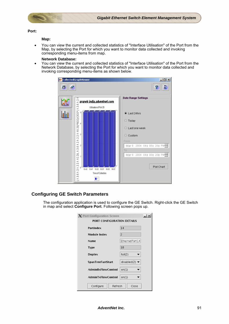
Gigabit Ethernet Switch Element Management System
Port:
Map: • You can view the current and collected statistics of "Interface Utilisation" of the Port from the
Map, by selecting the Port for which you want to monitor data collected and invoking corresponding menu-items from map. Network Database:
• You can view the current and collected statistics of "Interface Utilisation" of the Port from the Network Database, by selecting the Port for which you want to monitor data collected and invoking corresponding menu-items as shown below.
Configuring GE Switch Parameters
The configuration application is used to configure the GE Switch. Right-click the GE Switch in map and select Configure Port. Following screen pops up.
AdventNet Inc. 91

Gigabit Ethernet Switch Element Management System
Alerts from the GE Switch and Sub-components and Its Propagation
Try sending Traps from the SNMP Agent Simulator and check whether they are received under Fault Management and events are propagated. Select the Network Events node under Fault Management node in the tree. You can find events displayed in the right-side frame.
AdventNet Inc. 92
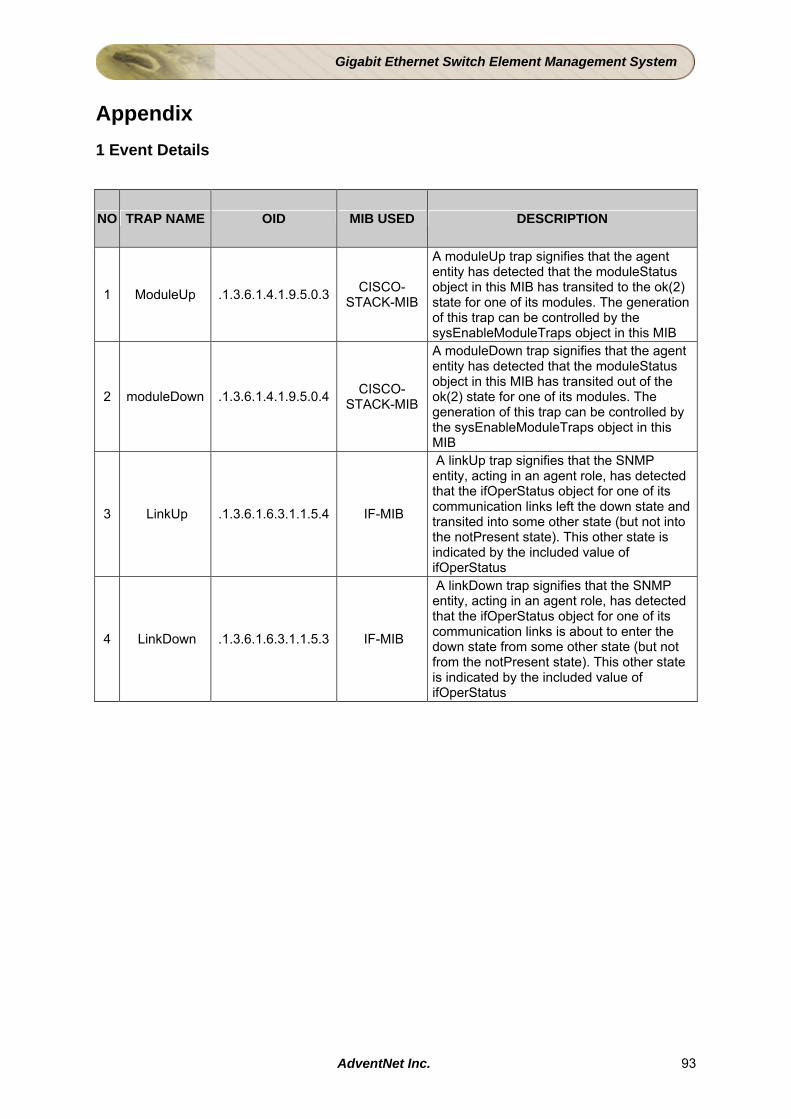
Gigabit Ethernet Switch Element Management System
Appendix 1 Event Details
NO TRAP NAME OID MIB USED DESCRIPTION
1 ModuleUp .1.3.6.1.4.1.9.5.0.3 CISCO-STACK-MIB
A moduleUp trap signifies that the agent entity has detected that the moduleStatus object in this MIB has transited to the ok(2) state for one of its modules. The generation of this trap can be controlled by the sysEnableModuleTraps object in this MIB
2 moduleDown .1.3.6.1.4.1.9.5.0.4 CISCO-STACK-MIB
A moduleDown trap signifies that the agent entity has detected that the moduleStatus object in this MIB has transited out of the ok(2) state for one of its modules. The generation of this trap can be controlled by the sysEnableModuleTraps object in this MIB
3 LinkUp .1.3.6.1.6.3.1.1.5.4 IF-MIB
A linkUp trap signifies that the SNMP entity, acting in an agent role, has detected that the ifOperStatus object for one of its communication links left the down state and transited into some other state (but not into the notPresent state). This other state is indicated by the included value of ifOperStatus
4 LinkDown .1.3.6.1.6.3.1.1.5.3 IF-MIB
A linkDown trap signifies that the SNMP entity, acting in an agent role, has detected that the ifOperStatus object for one of its communication links is about to enter the down state from some other state (but not from the notPresent state). This other state is indicated by the included value of ifOperStatus
AdventNet Inc. 93
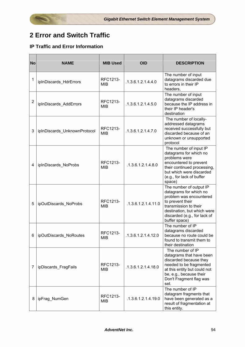
Gigabit Ethernet Switch Element Management System
2 Error and Switch Traffic IP Traffic and Error Information
No
NAME MIB Used OID DESCRIPTION
1 ipInDiscards_HdrErrors RFC1213-
MIB .1.3.6.1.2.1.4.4.0
The number of input datagrams discarded due to errors in their IP headers,
2 ipInDiscards_AddErrors RFC1213-
MIB .1.3.6.1.2.1.4.5.0
The number of input datagrams discarded because the IP address in their IP header's destination
3 ipInDiscards_UnknownProtocol RFC1213-MIB .1.3.6.1.2.1.4.7.0
The number of locally-addressed datagrams received successfully but discarded because of an unknown or unsupported protocol
4 ipInDiscards_NoProbs RFC1213-MIB .1.3.6.1.2.1.4.8.0
The number of input IP datagrams for which no problems were encountered to prevent their continued processing, but which were discarded (e.g., for lack of buffer space)
5 ipOutDiscards_NoProbs RFC1213-MIB .1.3.6.1.2.1.4.11.0
The number of output IP datagrams for which no problem was encountered to prevent their transmission to their destination, but which were discarded (e.g., for lack of buffer space)
6 ipOutDiscards_NoRoutes RFC1213-MIB .1.3.6.1.2.1.4.12.0
The number of IP datagrams discarded because no route could be found to transmit them to their destination
7 ipDiscards_FragFails RFC1213-MIB .1.3.6.1.2.1.4.18.0
The number of IP datagrams that have been discarded because they needed to be fragmented at this entity but could not be, e.g., because their Don't Fragment flag was set.
8 ipFrag_NumGen RFC1213-MIB .1.3.6.1.2.1.4.19.0
The number of IP datagram fragments that have been generated as a result of fragmentation at this entity.
AdventNet Inc. 94
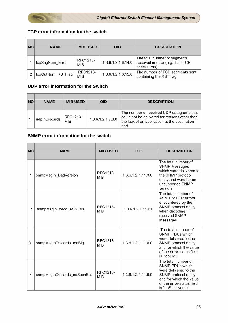
Gigabit Ethernet Switch Element Management System
TCP error information for the switch
NO NAME MIB USED OID DESCRIPTION
1 tcpSegNum_Error RFC1213-MIB .1.3.6.1.2.1.6.14.0
The total number of segments received in error (e.g., bad TCP checksums).
2 tcpOutNum_RSTFlag RFC1213-MIB .1.3.6.1.2.1.6.15.0 The number of TCP segments sent
containing the RST flag UDP error information for the Switch
NO NAME MIB USED OID DESCRIPTION
1 udpInDiscards RFC1213-MIB .1.3.6.1.2.1.7.3.0
The number of received UDP datagrams that could not be delivered for reasons other than the lack of an application at the destination port
SNMP error information for the switch
NO NAME MIB USED OID DESCRIPTION
1 snmpMsgIn_BadVersion RFC1213-MIB .1.3.6.1.2.1.11.3.0
The total number of SNMP Messages which were delivered to the SNMP protocol entity and were for an unsupported SNMP version
2 snmpMsgIn_deco_ASNErrs RFC1213-MIB .1.3.6.1.2.1.11.6.0
The total number of ASN.1 or BER errors encountered by the SNMP protocol entity when decoding received SNMP Messages
3 snmpMsgInDiscards_tooBig RFC1213-MIB .1.3.6.1.2.1.11.8.0
The total number of SNMP PDUs which were delivered to the SNMP protocol entity and for which the value of the error-status field is `tooBig'.
4 snmpMsgInDiscards_noSuchEnt RFC1213-MIB .1.3.6.1.2.1.11.9.0
The total number of SNMP PDUs which were delivered to the SNMP protocol entity and for which the value of the error-status field is `noSuchName'
AdventNet Inc. 95
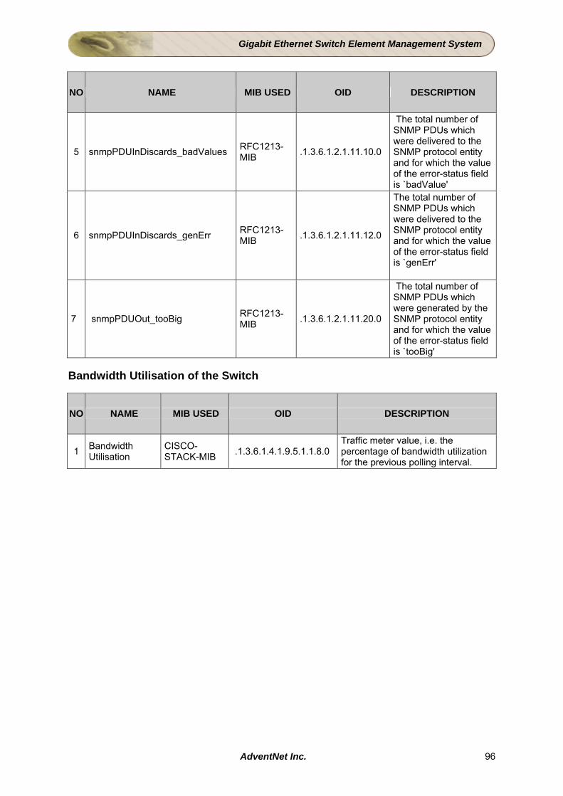
Gigabit Ethernet Switch Element Management System
NO NAME MIB USED OID DESCRIPTION
5 snmpPDUInDiscards_badValues RFC1213-MIB .1.3.6.1.2.1.11.10.0
The total number of SNMP PDUs which were delivered to the SNMP protocol entity and for which the value of the error-status field is `badValue'
6 snmpPDUInDiscards_genErr RFC1213-MIB .1.3.6.1.2.1.11.12.0
The total number of SNMP PDUs which were delivered to the SNMP protocol entity and for which the value of the error-status field is `genErr'
7 snmpPDUOut_tooBig RFC1213-MIB .1.3.6.1.2.1.11.20.0
The total number of SNMP PDUs which were generated by the SNMP protocol entity and for which the value of the error-status field is `tooBig'
Bandwidth Utilisation of the Switch
NO NAME MIB USED OID DESCRIPTION
1 Bandwidth Utilisation
CISCO-STACK-MIB .1.3.6.1.4.1.9.5.1.1.8.0
Traffic meter value, i.e. the percentage of bandwidth utilization for the previous polling interval.
AdventNet Inc. 96
Gigabit Ethernet Switch Element Management System
3 Calculating Interface Utilization Introduction This document describes how to calculate bandwidth utilization using Simple Network Management Protocol (SNMP). Solution Interface utilization is the primary measure used for network utilization. The following formulas should be used, based on whether the connection to be measured is half-duplex or full-duplex. Shared LAN connections tend to be half-duplex, mainly because contention detection expects a device to listen before transmitting. WAN connections typically are full-duplex, because the connection is point-to-point i.e., both devices can transmit and receive at the same time since there is only one other device sharing the connection. Because MIB-II variables are stored as counters, it is necessary to take two poll cycles and figure the difference between the two, hence, the delta used in the equation. The following explains the variables used in the formulas:
• ^ifInOctets: The () difference between, two poll cycles, of collecting the snmp ifInOctets object, which represents the count of inbound, octets of traffic.
• ^ifOutOctets: The difference between, two poll cycles, of collecting of the snmpifOutOctets object, which represents the count, of outbound, octets of traffic.
• IfSpeed: the speed of the interface, as represented in the snmpifSpeed object.
[^ refers to Delta]
For half-duplex media, use the following formula for interface utilization: (^ifInOctets+^ifOutOctets)x8x100 --------------------------------------------------- (number of seconds in ^)x IfSpeed [^ refers to Delta] For full-duplex media, calculating the utilization is trickier. For example, with a full T-1 serial connection, the line speed is 1.544 Mbps. What this means is that a T-1 interface can both receive and transmit 1.544 Mbps for a combined possible bandwidth of 3.088 Mbps! When calculating interface bandwidth for full-duplex connections, you could use the following formula, in which you take the larger of the in and out values and generate a utilization percentage: max(^ifInOctets+^ifOutOctets)x8x100 --------------------------------------------------- (number of seconds in ^)x IfSpeed [^ refers to Delta]
AdventNet Inc. 97
Gigabit Ethernet Switch Element Management System
However, this method hides the utilization of the direction that has the lesser value and provides less accurate results. A more accurate method is to measure the input utilization and output utilization separately, using the following formulae: Input utilization = ^ifInOctetsx8x100 ----------------------------------- (number of seconds in ^)x IfSpeed Output utilization = ^ifOutOctetsx8x100 ----------------------------------- (number of seconds in ^)x IfSpeed [^ refers to Delta] These formulas are somewhat simplified because they do not take into consideration any overhead associated with the particular protocol. As an example, refer to RFC 1757 Ethernet-utilization formulas that take into consideration packet overhead. All of the MIB attributes listed above are found in RFC1213 MIB. Details of the MIB variables used in these formulas are as follows: .1.3.6.1.2.1.2.2.1.10 ifInOctets OBJECT-TYPE -- FROM RFC1213-MIB, IF-MIB SYNTAX Counter MAX-ACCESS read-only STATUS Mandatory DESCRIPTION "The total number of octets received on the interface, including framing characters." ::= { iso(1) org(3) dod(6) internet(1) mgmt(2) mib-2(1) interfaces(2) ifTable(2) ifEntry(1) 10 } .1.3.6.1.2.1.2.2.1.16 .1.3.6.1.2.1.2.2.1.16 ifOutOctets OBJECT-TYPE -- FROM RFC1213-MIB, IF-MIB SYNTAX Counter MAX-ACCESS read-only STATUS Mandatory DESCRIPTION "The total number of octets transmitted out of the interface, including framing characters." ::= { ISO(1) org(3) DOD(6) Internet(1) mgmt(2) mib-2(1) interfaces(2) ifTable(2) ifEntry(1) 16 } .1.3.6.1.2.1.2.2.1.5 ifSpeed OBJECT-TYPE -- FROM RFC1213-MIB, IF-MIB SYNTAX Gauge MAX-ACCESS read-only STATUS Mandatory DESCRIPTION "An estimate of the interface's current bandwidth in bits per second. For interfaces which do not vary in bandwidth or for those where no accurate estimation can be made, this object should contain the nominal bandwidth." ::= { ISO(1) org(3) DOD(6) Internet(1) mgmt(2) mib-2(1) interfaces(2) ifTable(2) ifEntry(1) 5 }
AdventNet Inc. 98