Embed Size (px)
Citation preview
GIIGNL - WORLDWIDE EXPERIENCE OF LNG IMPORT TERMINAL & POWER PLANT INTEGRATIONS
Philippe BOUCHY
Head of the Technical Division “Management and operation” at the Technical Department of ELENGY Bois-Colombes, France
Secil TORUN LNG, LPG Research Program Manager
ENGIE Research & Technologies Division, France
Hugues MALVOS
LNG Expert ENGIE
Research & Technologies Division, France
E-mail: [email protected] Website: www.giignl.org
ABSTRACT In order to promote best and safe practices within the LNG importers’ community, GIIGNL is
willing to share several findings of a work carried out on the possible synergies between LNG import terminal & power plant.
With growing concern about environmental issues and increasing of electricity prices, the integration of the two processes are opportunities to be considered.
The GIIGNL work focused on conventional on-shore LNG import terminals, all types of power
plants and analyzed integration of heat and power between these terminals and power plants.
Five kinds of synergies have been implemented on terminals worldwide. Through this work, they
have been analyzed along with the associated feedback of GIIGNL members. Advantages, drawbacks and condition(s) for success for each type of LNG terminal and power plant integration
have been identified.
Page 2 of 11
GIIGNL ANALYSIS SCOPE OF WORK A large number of power plants projects are being developed worldwide, some of them having the possibility to be supplied by gas from a LNG receiving terminal. As both plants have
complementary thermal waste they need to evacuate, integrating them can bring several kinds of interesting synergies.
Hence, GIIGNL recently completed an analysis on worldwide experiences of LNG import terminal
& power plant integration.
The boundaries were the followings :
LNG import terminals: conventional on-shore ones
Power plants: all types
Type of Integration: heat & power, only between LNG terminals & power plants
A synergy is defined as a cooperation for energy exchange between a LNG import terminal and a
power generation unit aiming to bring savings for at least one of the two involved industries. Savings can be of different types: environmental, economical, utility or manpower sharing, safety
improvements. The terms “synergy” and “integration” are both used in this report.
The aim of the GIIGNL analysis was to provide its members with information to guide their choice
toward the implementation of the most suitable synergy for their potential projects.
AVAILABLE ENERGY AT LNG IMPORT TERMINALS At liquefaction plants, cold energy is produced when cooling down and condensing the natural gas to approximately -160°C. As a result, natural gas volume is reduced 600 times which enables
economic shipment by tankers. At LNG terminals, LNG is vaporized and cold energy stored in it is
simply released to the environment. AVAILABLE ENERGY FROM LNG TEMPERATURE
The first form of recoverable energy at LNG terminal is thermal energy. Considering that LNG vaporization processes are done at constant pressure, thermodynamic laws indicate that the
thermal energy released by its vaporization corresponds to its enthalpy variation. Under such conditions (supercritical), LNG enthalpy variation equals to its heat mass capacity multiplied by its
temperature variation:
𝑑𝐻 = 𝐶𝑃(𝑇). 𝑑𝑇
Heat mass capacity is a material characteristic and represents the required thermal energy to
increase the temperature of 1 kg of considered material by 1K. In other words, it represents the material capacity to absorb or return energy by thermal transfer.
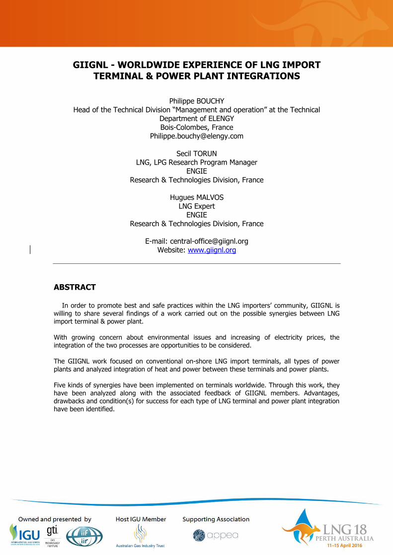
The figure 1 below represents the variation of LNG heat mass as a function of the temperature. The pressure is constant and equal to 80 bar and LNG composition is given by the standard EN
11601.
The increase of enthalpy during the vaporization process is not linear. The yellow part represents the total thermal energy which is produced during the LNG vaporization process. It is equal to
approximately 732 MJ/ton of LNG (from -160°C to 10°C). For a typical 5 MTPA (600 tons of LNG/h) terminal, it represents 122 MW of available thermal energy. The amount of thermal
energy available is maximum between -70°C and -50°C.
{
𝑑𝐻 ∶ 𝑒𝑛𝑡ℎ𝑎𝑙𝑝𝑦 𝑣𝑎𝑟𝑖𝑎𝑡𝑖𝑜𝑛 (𝑘𝐽. 𝑘𝑔−1)
𝐶𝑝 ∶ ℎ𝑒𝑎𝑡 𝑚𝑎𝑠𝑠 𝑐𝑎𝑝𝑎𝑐𝑖𝑡𝑦 (𝑘𝐽. 𝑘𝑔−1. 𝐾−1)
𝑑𝑇 ∶ 𝑡𝑒𝑚𝑝𝑒𝑟𝑎𝑡𝑢𝑟𝑒 𝑣𝑎𝑟𝑖𝑎𝑡𝑖𝑜𝑛 (𝐾)
Page 3 of 11
Figure 1 – LNG heat mass depending on its temperature, p = 80 bar, EN1160 LNG composition
The second form of energy that can be released from stored cold is work. To produce work from thermal energy, two thermal sources are needed: a hot one and a cold one. The heat energy
cannot be entirely turned into work energy. The maximum retrievable from a thermal source is represented by the exergy. Considering an ideal cycle (e.g. Carnot cycle) without irreversibility,
thermodynamics laws gives the cycle cold efficiency:
𝑊 = 𝜂𝑄𝑐𝑜𝑙𝑑 𝑤𝑖𝑡ℎ ∶ 𝜂 =𝑇ℎ𝑜𝑡
𝑇𝑐𝑜𝑙𝑑− 1
The cycle cold efficiency represents the maximum recoverable work from one amount of heat exchanged between a hot source and a cold one in an ideal cycle.
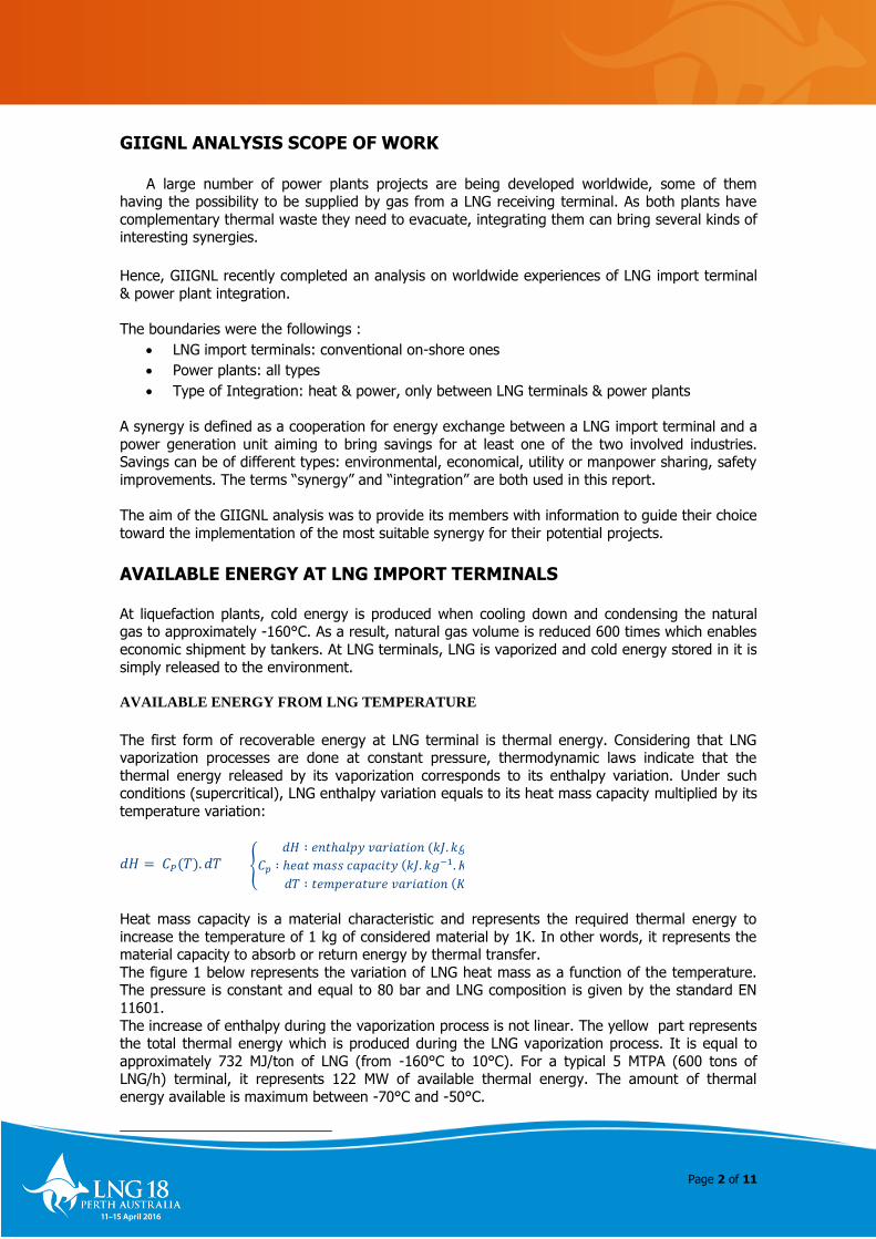
Figure 2 – Variation of cold cycle efficiency depending on the cold source temperature
Figure 2 shows cold efficiency
variation using a 15°C hot
source and a cold one at T, temperature between -160°C
and 10°C (cold source representing here LNG). As
depicted in the figure, ideal cycle cold efficiency decreases
when cold source temperature
increases. It means that the greater the gap between cold
and hot sources temperatures is, the higher the work
production will be. The overall
work which can be produced from LNG cold is equal to 413
MJ/ton of LNG (in case of perfect cycle).
{
𝜂 ∶ 𝑐𝑦𝑐𝑙𝑒 𝑐𝑜𝑙𝑑 𝑒𝑓𝑓𝑖𝑐𝑖𝑒𝑛𝑐𝑦 (%)
𝑊 ∶ 𝑤𝑜𝑟𝑘 𝑝𝑟𝑜𝑣𝑖𝑑𝑒𝑑 𝑏𝑦 𝑡ℎ𝑒 𝑐𝑦𝑐𝑙𝑒 (𝑘𝐽. 𝑘𝑔−1)
𝑄𝑐𝑜𝑙𝑑 ∶ ℎ𝑒𝑎𝑡 𝑡𝑟𝑎𝑛𝑠𝑓𝑒𝑟𝑒𝑑 𝑡𝑜 𝑐𝑜𝑙𝑑 𝑠𝑜𝑢𝑟𝑐𝑒 (𝑘𝐽. 𝑘𝑔−1)
𝑇ℎ𝑜𝑡 ∶ ℎ𝑜𝑡 𝑠𝑜𝑢𝑟𝑐𝑒 𝑡𝑒𝑚𝑝𝑒𝑟𝑎𝑡𝑢𝑟𝑒 (𝐾) 𝑇𝑐𝑜𝑙𝑑 ∶ 𝑐𝑜𝑙𝑑 𝑠𝑜𝑢𝑟𝑐𝑒 𝑡𝑒𝑚𝑝𝑒𝑟𝑎𝑡𝑢𝑟𝑒 (𝐾)
Page 4 of 11
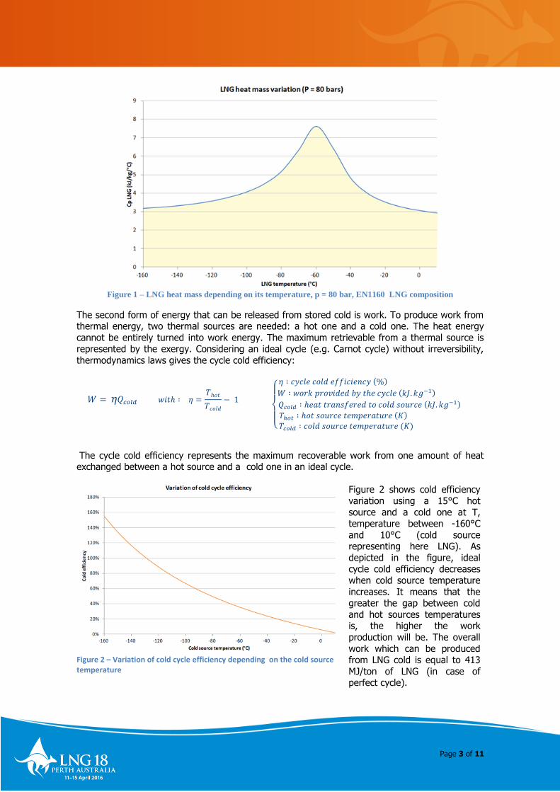
Figure 3 gives the production of thermal energy and work from LNG vaporization depending on
the LNG temperature. About 30% of LNG thermal energy between -160°C and -100°C enables to
produce 56% of the total work. Moreover, around 80% of the total work is produced using LNG at temperatures between -160°C and -60°C. From -60°C to -10°C, 40% of the total thermal
energy is produced. Hence, regarding investments for energy recovery systems, a thermodynamic cycle to produce work should be installed using LNG flows between -160°C and -
60°C. The rest of LNG energy could be used to direct thermal applications. To maximize the work production efficiency, the working fluid should be chosen for its ability to exchange at all LNG
temperatures.
Figure 3 – Evolution of thermal energy & work production depending on LNG temperature (cold source),
starting from – 160°C
AVAILABLE ENERGY FROM LNG PRESSURE
Both forms of energy released from cold (thermal energy & work), are derived from the
temperature difference between LNG and its surrounding environment.
Depending on the regasification pressure and on the required gas pressure on gas grid, some
LNG terminals could also produce energy from the expansion process of gas. Thermodynamic laws indicate the work which can be produced by expanding natural gas through a turbine:
𝑊 = 𝑅𝑆𝑟. 𝑍. 𝑇𝑖𝑛𝑎
( 𝑃𝑜𝑢𝑡
𝑃𝑖𝑛
𝑎
− 1)
𝑤𝑖𝑡ℎ ∶ 𝑎 =𝛾 − 1
𝛾 𝑎𝑛𝑑 𝑟 =
𝑅
𝑀
The following graphic shows the work produced by direct gas expansion for a typical 5 MTPA LNG
terminal (600 tons of LNG/h) and the corresponding turbine outlet temperature for different
outlet pressures. The turbine inlet pressure corresponds to the regasification pressure and is fixed at 80 bars. The gas temperature at the turbine inlet is equal to the gas temperature after
vaporization. It is fixed at 5°C.
{
𝑊 ∶ 𝑤𝑜𝑟𝑘 𝑝𝑟𝑜𝑣𝑖𝑑𝑒𝑑 𝑏𝑦 𝑡ℎ𝑒 𝑁𝐺 𝑒𝑥𝑝𝑎𝑛𝑠𝑖𝑜𝑛 (𝐽. 𝑘𝑔−1)
𝑅𝑆 ∶ 𝑖𝑠𝑒𝑛𝑡𝑟𝑜𝑝𝑖𝑐 𝑒𝑓𝑓𝑖𝑐𝑖𝑒𝑛𝑐𝑡 (𝑅𝑆 = 0.85)
𝑅 ∶ 𝑔𝑎𝑠 𝑐𝑜𝑛𝑠𝑡𝑎𝑛𝑡 (𝑅 = 8.314 𝐽. 𝑘𝑔−1. 𝑚𝑜𝑙−1)
𝑀 ∶ 𝑚𝑜𝑙𝑎𝑟 𝑚𝑎𝑠𝑠 𝑜𝑓 𝑡ℎ𝑒 𝑁𝐺 (𝑘𝑔.𝑚𝑜𝑙−1) 𝑍 ∶ 𝑐𝑜𝑚𝑝𝑟𝑒𝑠𝑠𝑖𝑏𝑖𝑙𝑖𝑡𝑦 𝑓𝑎𝑐𝑡𝑜𝑟
𝛾 ∶ 𝑝𝑜𝑙𝑦𝑡𝑟𝑜𝑝𝑖𝑐 𝑐𝑜𝑒𝑓𝑓𝑖𝑐𝑖𝑒𝑛𝑡 (𝛾 = 1.4)
𝑇𝑖𝑛 ∶ 𝑡𝑒𝑚𝑝𝑒𝑟𝑎𝑡𝑢𝑟𝑒 𝑎𝑡 𝑡ℎ𝑒 𝑖𝑛𝑙𝑒𝑡 𝑜𝑓 𝑡ℎ𝑒 𝑡𝑢𝑟𝑏𝑖𝑛𝑒 (𝐾)
𝑃𝑖𝑛 ∶ 𝑝𝑟𝑒𝑠𝑠𝑢𝑟𝑒 𝑎𝑡 𝑡ℎ𝑒 𝑖𝑛𝑙𝑒𝑡 𝑜𝑓 𝑡ℎ𝑒 𝑡𝑢𝑟𝑏𝑖𝑛𝑒 (𝑃𝑎)
𝑃𝑜𝑢𝑡 ∶ 𝑝𝑟𝑒𝑠𝑠𝑢𝑟𝑒 𝑎𝑡 𝑡ℎ𝑒 𝑜𝑢𝑡𝑙𝑒𝑡 𝑜𝑓 𝑡ℎ𝑒 𝑡𝑢𝑟𝑏𝑖𝑛𝑒 (𝑃𝑎)

Page 5 of 11
As shown on Figure 4, the amount of work produced increases when the turbine outlet pressure
decreases. The maximum work that can be produced by direct expansion in this case is equal to
24 MW for a turbine outlet pressure of 10 bars.
However, decreasing the turbine outlet pressure also leads to decreasing the gas outlet
temperature. Then there is a risk to reach the natural gas dew point which could create problems for the Turbine. Expanding the gas from 80 bars to 10 bars leads to a decrease of the
temperature from 5°C to -120°C. The natural gas dew point is not reached in this case and all components stay in a gaseous state.
Another consequence of the drop in temperature is the need to heat the gas after expansion to
meet gas grid requirements.
Direct gas expansion is widely used in Asia where the network pressure is very low.
Figure 4 – Evolution of work produced by direct gas expansion & corresponding gas outlet temperature
depending on turbine outlet pressure (Inlet pressure set at 80 bar).
Page 6 of 11
SYNERGIES FOR USING AVAILABLE ENERGY
During the regasification process of LNG, any sensible heat required to heat up the gas have to
be supplied to the LNG. On the other hand, power plants produce heat they need to evacuate. Usually LNG receiving terminals discharge into the environment the LNG cold which is released
from regasification process, while it could be recovered for power plants operations. Re-using LNG cold would provide energy savings and reduce the environmental impact.
Moreover, LNG terminal electricity needs could be met by an on-site power generation unit, reducing the need for imports from the electricity grid.
Five major types of synergies between LNG terminals and power plants have been developed
worldwide. Based on scientific publications and specific technical reports, they are described
below. In order to help the reader to quickly identify the synergy under discussion, a logotype is associated to each one.
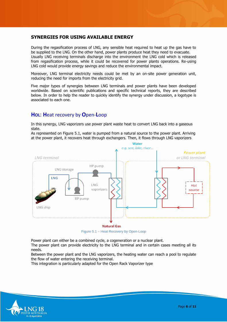
HOL: Heat recovery by Open-Loop
In this synergy, LNG vaporizers use power plant waste heat to convert LNG back into a gaseous
state. As represented on Figure 5.1, water is pumped from a natural source to the power plant. Arriving
at the power plant, it recovers heat through exchangers. Then, it flows through LNG vaporizers where it is cooled down and sent back to its initial source.
Figure 5.1 – Heat Recovery by Open-Loop
Power plant can either be a combined cycle, a cogeneration or a nuclear plant.
The power plant can provide electricity to the LNG terminal and in certain cases meeting all its needs.
Between the power plant and the LNG vaporizers, the heating water can reach a pool to regulate
the flow of water entering the receiving terminal. This integration is particularly adapted for the Open Rack Vaporizer type
Page 7 of 11
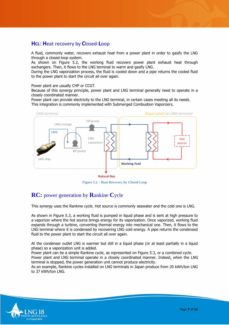
HCL: Heat recovery by Closed-Loop
A fluid, commonly water, recovers exhaust heat from a power plant in order to gasify the LNG
through a closed-loop system. As shown on Figure 5.2, the working fluid recovers power plant exhaust heat through
exchangers. Then, it flows to the LNG terminal to warm and gasify LNG. During the LNG vaporization process, the fluid is cooled down and a pipe returns the cooled fluid
to the power plant to start the circuit all over again.
Power plant are usually CHP or CCGT.
Because of this synergy principle, power plant and LNG terminal generally need to operate in a closely coordinated manner.
Power plant can provide electricity to the LNG terminal, in certain cases meeting all its needs. This integration is commonly implemented with Submerged Combustion Vaporizers.
Figure 5.2 – Heat Recovery by Closed-Loop
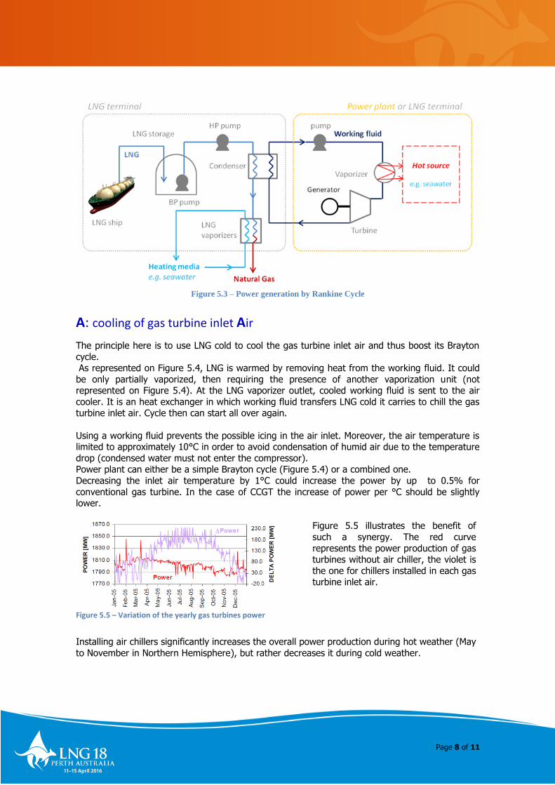
RC: power generation by Rankine Cycle
This synergy uses the Rankine cycle. Hot source is commonly seawater and the cold one is LNG.
As shown in Figure 5.3, a working fluid is pumped in liquid phase and is sent at high pressure to a vaporizer where the hot source brings energy for its vaporization. Once vaporized, working fluid
expands through a turbine, converting thermal energy into mechanical one. Then, it flows to the LNG terminal where it is condensed by recovering LNG cold energy. A pipe returns the condensed
fluid to the power plant to start the circuit all over again.
At the condenser outlet LNG is warmer but still in a liquid phase (or at least partially in a liquid
phase) so a vaporization unit is added. Power plant can be a simple Rankine cycle, as represented on Figure 5.3, or a combined cycle.
Power plant and LNG terminal operate in a closely coordinated manner. Indeed, when the LNG terminal is stopped, the power generation unit cannot produce electricity.
As an example, Rankine cycles installed on LNG terminals in Japan produce from 20 kWh/ton LNG
to 37 kWh/ton LNG.
Page 8 of 11
Figure 5.3 – Power generation by Rankine Cycle
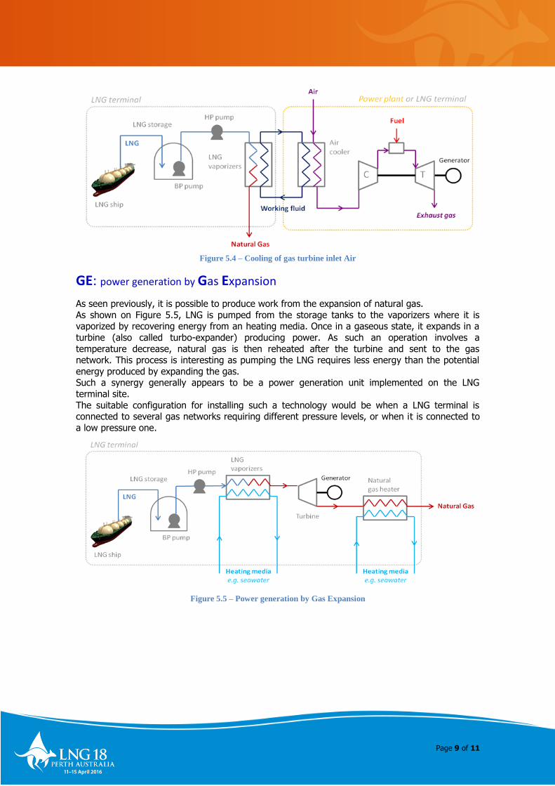
A: cooling of gas turbine inlet Air
The principle here is to use LNG cold to cool the gas turbine inlet air and thus boost its Brayton
cycle. As represented on Figure 5.4, LNG is warmed by removing heat from the working fluid. It could
be only partially vaporized, then requiring the presence of another vaporization unit (not represented on Figure 5.4). At the LNG vaporizer outlet, cooled working fluid is sent to the air
cooler. It is an heat exchanger in which working fluid transfers LNG cold it carries to chill the gas turbine inlet air. Cycle then can start all over again.
Using a working fluid prevents the possible icing in the air inlet. Moreover, the air temperature is limited to approximately 10°C in order to avoid condensation of humid air due to the temperature
drop (condensed water must not enter the compressor). Power plant can either be a simple Brayton cycle (Figure 5.4) or a combined one.
Decreasing the inlet air temperature by 1°C could increase the power by up to 0.5% for
conventional gas turbine. In the case of CCGT the increase of power per °C should be slightly lower.
Figure 5.5 – Variation of the yearly gas turbines power
Figure 5.5 illustrates the benefit of
such a synergy. The red curve
represents the power production of gas turbines without air chiller, the violet is
the one for chillers installed in each gas turbine inlet air.
Installing air chillers significantly increases the overall power production during hot weather (May
to November in Northern Hemisphere), but rather decreases it during cold weather.
Page 9 of 11
Figure 5.4 – Cooling of gas turbine inlet Air
GE: power generation by Gas Expansion
As seen previously, it is possible to produce work from the expansion of natural gas.
As shown on Figure 5.5, LNG is pumped from the storage tanks to the vaporizers where it is vaporized by recovering energy from an heating media. Once in a gaseous state, it expands in a
turbine (also called turbo-expander) producing power. As such an operation involves a
temperature decrease, natural gas is then reheated after the turbine and sent to the gas network. This process is interesting as pumping the LNG requires less energy than the potential
energy produced by expanding the gas. Such a synergy generally appears to be a power generation unit implemented on the LNG
terminal site.
The suitable configuration for installing such a technology would be when a LNG terminal is connected to several gas networks requiring different pressure levels, or when it is connected to
a low pressure one.
Figure 5.5 – Power generation by Gas Expansion
Page 10 of 11
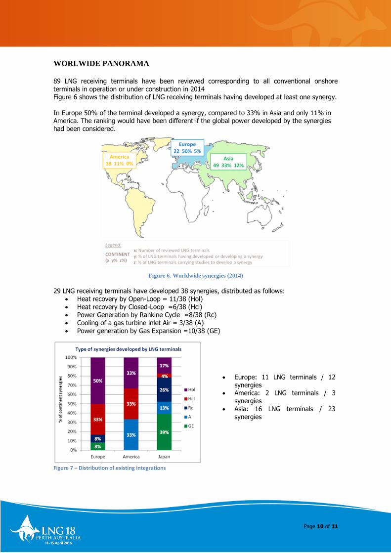
WORLWIDE PANORAMA
89 LNG receiving terminals have been reviewed corresponding to all conventional onshore
terminals in operation or under construction in 2014 Figure 6 shows the distribution of LNG receiving terminals having developed at least one synergy.
In Europe 50% of the terminal developed a synergy, compared to 33% in Asia and only 11% in America. The ranking would have been different if the global power developed by the synergies
had been considered.
Figure 6. Worldwide synergies (2014)
29 LNG receiving terminals have developed 38 synergies, distributed as follows:
Heat recovery by Open-Loop = 11/38 (Hol)
Heat recovery by Closed-Loop =6/38 (Hcl)
Power Generation by Rankine Cycle =8/38 (Rc)
Cooling of a gas turbine inlet Air = 3/38 (A)
Power generation by Gas Expansion =10/38 (GE)
Figure 7 – Distribution of existing integrations
Europe: 11 LNG terminals / 12
synergies America: 2 LNG terminals / 3
synergies
Asia: 16 LNG terminals / 23
synergies

Page 11 of 11
As shown on Figure 7, Heat recovery by Open-Loop from adjacent power plant is the most
popular existing synergy. With the Heat recovery by closed-Loop, it has the particularity to be
developed on the 3 continents. Heat recovery solutions are widely developed in Europe. This could be because industrials who
opt for such synergies are often encouraged by receiving subsidies from governments
CONCLUSION
Natural Gas is the cleanest fossil fuel and has one of the lowest capital costs per MW. In a
worldwide context where environmental issues are of most importance, and where electricity prices are expected to increase, developing synergies could represent an even more interesting
and valuable solution.
Indeed, 29 LNG receiving terminals (i.e. more than 32 % of the conventional terminals part of
this study) developed 38 different synergies of five different types.
In the GIIGNL work, the possible synergies solutions have been discussed along with the
associated experiences feedback in order to help research for a better synergy.
It is nonetheless important to notice that every project is different and impacted by numerous factors which can widely vary from a country to another (weather, political, regulations, laws...)
and are really difficult to “standardize”, making site-specific feasibility studies mandatory.


![„The draft GIIGNL voyage charterparty for LNG shipping …final].pdf · „The draft GIIGNL voyage charterparty for LNG shipping and ... General exceptions clause 31 ... 6 This](https://img.pdfslide.net/doc/110x75/5b4168ed7f8b9a51528dcb27/the-draft-giignl-voyage-charterparty-for-lng-shipping-finalpdf-the-draft.jpg)