Embed Size (px)
Citation preview

Copyright © 2017 Gemtek Technology Corporation. All Rights Reserved
GIoT Femto Cell User Guide
Document Number QW_02_0022.003

1 Copyright © 2017 Gemtek Technology Corporation. All Rights Reserved
QW_02_0022.003
Table of Contents TABLE OF CONTENTS .......................................................................................................................... 1 GIOT FEMTO CELL - PRODUCT INTRODUCTION .................................................................................. 5
PRODUCT DESIGN ............................................................................................................................... 5 PRODUCT FEATURES ............................................................................................................................ 5 PRODUCT DETAILS .............................................................................................................................. 6
LED Indicators............................................................................................................................ 6 I/O Ports .................................................................................................................................... 7
PRODUCT SPECIFICATIONS .................................................................................................................... 8 Hardware Specification .............................................................................................................. 8 Software Specification ............................................................................................................... 9 LoRa Specification ................................................................................................................... 10 LoRa RF Specification ............................................................................................................... 10 Regulatory Specification .......................................................................................................... 11 Reliability Specification ............................................................................................................ 11
GIOT FEMTO CELL - WEBUI USER GUIDE .......................................................................................... 12 1. GIOT MODE............................................................................................................................. 12
1.1 OPEN ADMIN GUI .............................................................................................................. 12 1.2 STATUS ............................................................................................................................ 13
1.2.1 Overview ................................................................................................................... 13 1.2.2 Routes ....................................................................................................................... 15 1.2.3 System Log ................................................................................................................ 16 1.2.4 Kernel log .................................................................................................................. 16 1.2.5 Processes ................................................................................................................... 17 1.2.6 Realtime Graphs ........................................................................................................ 17
1.3 GIOT ............................................................................................................................... 19 1.3.1 Status ........................................................................................................................ 19 1.3.2 Provision .................................................................................................................... 20 1.3.3 Configuration ............................................................................................................. 20 1.3.4 Channel Scan ............................................................................................................. 21 1.3.5 GPS MAP ................................................................................................................... 21
1.4 SYSTEM ............................................................................................................................ 22 1.4.1 System ....................................................................................................................... 22 1.4.2 Administration ........................................................................................................... 23 1.4.3 Backup....................................................................................................................... 23 1.4.4 System Firmware ....................................................................................................... 24 1.4.5 Reboot ....................................................................................................................... 25
1.5 NETWORK ......................................................................................................................... 25 1.5.1 WAN .......................................................................................................................... 25 1.5.2 Wireless ..................................................................................................................... 28 1.5.3 LAN............................................................................................................................ 28 1.5.4 DHCP ......................................................................................................................... 28 1.5.5 Static Routes .............................................................................................................. 29 1.5.6 Diagnostic.................................................................................................................. 30
2. LORAWAN MODE.................................................................................................................... 32 2.1 OPEN ADMIN GUI .............................................................................................................. 32 2.2 STATUS ............................................................................................................................ 33
2.2.1 Overview ................................................................................................................... 33 2.2.2 Routes ....................................................................................................................... 35 2.2.3 System Log ................................................................................................................ 36 2.2.4 Kernel log .................................................................................................................. 36

2 Copyright © 2017 Gemtek Technology Corporation. All Rights Reserved
QW_02_0022.003
2.2.5 Processes ................................................................................................................... 37 2.2.6 Realtime Graphs ........................................................................................................ 37
2.3 SYSTEM ............................................................................................................................ 39 2.3.1 System ....................................................................................................................... 39 2.3.2 Administration ........................................................................................................... 40 2.3.3 Backup....................................................................................................................... 40 2.3.4 System Firmware ....................................................................................................... 41 2.3.5 Reboot ....................................................................................................................... 42
2.4 GIOT ............................................................................................................................... 42 2.4.1 Status ........................................................................................................................ 42 2.4.2 Provision .................................................................................................................... 43 2.4.3 Configuration ............................................................................................................. 43 2.4.4 Network Server .......................................................................................................... 44 2.4.5 Network Server Log .................................................................................................... 44 2.4.6 Channel Scan ............................................................................................................. 45 2.4.7 GPS MAP ................................................................................................................... 45
2.5 LORAWAN ....................................................................................................................... 46 2.5.1 OTAA Status............................................................................................................... 46 2.5.2 Node Parameters ....................................................................................................... 46 2.5.3 OTAA ......................................................................................................................... 47 2.5.4 ABP............................................................................................................................ 49 2.5.5 INDIVIDUAL ............................................................................................................... 49
2.6 NETWORK ......................................................................................................................... 53 2.6.1 WAN .......................................................................................................................... 53 2.6.2 Wireless ..................................................................................................................... 56 2.6.3 LAN............................................................................................................................ 56 2.6.4 DHCP ......................................................................................................................... 57 2.6.5 Static Routes .............................................................................................................. 57 2.6.6 Diagnostic.................................................................................................................. 58
3. EDUCATION MODE ................................................................................................................. 60 3.1 OPEN ADMIN GUI .............................................................................................................. 60 3.2 STATUS ............................................................................................................................ 61
3.2.1 Overview ................................................................................................................... 61 3.2.2 Routes ....................................................................................................................... 63 3.2.3 System Log ................................................................................................................ 64 3.2.4 Kernel Log .................................................................................................................. 64 3.2.5 Processes ................................................................................................................... 65 3.2.6 Realtime Graphs ........................................................................................................ 65
3.3 SYSTEM ............................................................................................................................ 67 3.3.1 System ....................................................................................................................... 67 3.3.2 Administration ........................................................................................................... 68 3.3.3 Backup....................................................................................................................... 68 3.3.4 Reboot ....................................................................................................................... 69
3.4 GIOT ............................................................................................................................... 70 3.4.1 Status ........................................................................................................................ 70 3.4.2 Provision .................................................................................................................... 70 3.4.3 Configuration ............................................................................................................. 71 3.4.4 Network Server .......................................................................................................... 71 3.4.5 Network Server Log .................................................................................................... 72 3.4.6 Channel Scan ............................................................................................................. 73 3.4.7 Channel Setting .......................................................................................................... 73 3.4.8 GPS MAP ................................................................................................................... 74
3.5 LORAWAN ....................................................................................................................... 74 3.5.1 OTAA Status............................................................................................................... 74 3.5.2 Node Parameters ....................................................................................................... 75 3.5.3 OTAA ......................................................................................................................... 76

3 Copyright © 2017 Gemtek Technology Corporation. All Rights Reserved
QW_02_0022.003
3.5.4 ABP............................................................................................................................ 78 3.6 NETWORK ......................................................................................................................... 82
3.6.1 WAN .......................................................................................................................... 82 3.6.2 Wireless ..................................................................................................................... 85 3.6.3 LAN............................................................................................................................ 85 3.6.4 DHCP ......................................................................................................................... 85 3.6.5 Static Routes .............................................................................................................. 86 3.6.6 Diagnostic.................................................................................................................. 87
4. LORAWAN BRIDGE MODE ....................................................................................................... 89 4.1 OPEN ADMIN GUI .............................................................................................................. 89 4.2 STATUS ............................................................................................................................ 90
4.2.1 Overview ................................................................................................................... 90 4.2.2 Routes ....................................................................................................................... 92 4.2.3 System Log ................................................................................................................ 93 4.2.4 Kernel log .................................................................................................................. 93 4.2.5 Processes ................................................................................................................... 94 4.2.6 Realtime Graphs ........................................................................................................ 94
4.3 GIOT ............................................................................................................................... 96 4.3.1 Status ........................................................................................................................ 96 4.3.2 Provision .................................................................................................................... 97 4.3.3 Configuration ............................................................................................................. 97 4.3.4 Network Server .......................................................................................................... 98 4.3.5 Network Server Log .................................................................................................... 99 4.3.6 Channel Scan ........................................................................................................... 100 4.3.7 GPS MAP ................................................................................................................. 100
4.4 SYSTEM .......................................................................................................................... 101 4.4.1 System ..................................................................................................................... 101 4.4.2 Administration ......................................................................................................... 102 4.4.3 Backup..................................................................................................................... 102 4.4.4 Reboot ..................................................................................................................... 103
4.5 NETWORK ....................................................................................................................... 103 4.5.1 WAN ........................................................................................................................ 103 4.5.2 Wireless ................................................................................................................... 106 4.5.3 LAN.......................................................................................................................... 107 4.5.4 DHCP ....................................................................................................................... 107 4.5.5 Static Routes ............................................................................................................ 108 4.5.6 Diagnostic................................................................................................................ 108
5. GIOT (CN) MODE ................................................................................................................... 110 5.1 OPEN ADMIN GUI ............................................................................................................ 110 5.2 STATUS .......................................................................................................................... 111
5.2.1 Overview ................................................................................................................. 111 5.2.2 Routes ..................................................................................................................... 113 5.2.3 System Log .............................................................................................................. 113 5.2.4 Kernel log ................................................................................................................ 114 5.2.5 Processes ................................................................................................................. 114 5.2.6 Realtime Graphs ...................................................................................................... 115
5.3 GIOT ............................................................................................................................. 117 5.3.1 Status ...................................................................................................................... 117 5.3.2 Provision .................................................................................................................. 117 5.3.3 Configuration ........................................................................................................... 118 5.3.4 Network Server ........................................................................................................ 119 5.3.5 Network Server Log .................................................................................................. 120 5.3.6 Channel Scan ........................................................................................................... 120 5.3.7 Channel Setting ........................................................................................................ 121 5.3.8 GPS MAP ................................................................................................................. 121

4 Copyright © 2017 Gemtek Technology Corporation. All Rights Reserved
QW_02_0022.003
5.4 SYSTEM .......................................................................................................................... 122 5.4.1 System ..................................................................................................................... 122 5.4.2 Administration ......................................................................................................... 123 5.4.3 Backup..................................................................................................................... 123 5.4.4 System Firmware ..................................................................................................... 124 5.4.5 Reboot ..................................................................................................................... 125
5.5 NETWORK ....................................................................................................................... 125 5.5.1 WAN ........................................................................................................................ 125 5.5.2 LAN.......................................................................................................................... 127 5.5.3 DHCP ....................................................................................................................... 127 5.5.4 Static Routes ............................................................................................................ 128 5.5.5 Diagnostic................................................................................................................ 129
GLOSSARY AND REFERENCES ......................................................................................................... 131 DEFINITIONS, ACRONYMS AND ABBREVIATIONS ...................................................................................... 131 REFERENCE ................................................................................................................................... 131

5 Copyright © 2017 Gemtek Technology Corporation. All Rights Reserved
QW_02_0022.003
GIoT Femto Cell - Product Introduction Product Design The dimension of the GIoT Femto Gateway WLRGFM-100 is 116 x 91 x 27 mm, which it comes with one external LoRa antenna, one WAN port and one USB 2.0 connector.
Product Features - In compliance with the latest LoRaWAN specification v1.0.2 and Regional Parameters v1.0.2 - Wide frequency range from 470MHz to 928MHz in different SKU - Up to 8 concurrent channels for LoRa transmission - Works with GIoT network server (GIoT mode) by default - Embedded network server or packet forward mode to work with 3rd party network server - Two classes of LoRa end-device are supported- Class A and Class C - Two activation methods- ABP and OTAA - Active scan for channel availability with RSSI levels - Supports Listen-Before-Talk (LBT) for downlink - Built-in 2.4GHz 802.11b/g/n Wireless LAN, as AP or repeater mode - Firmware can be upgraded via OTA or USB port - Heart beat for monitoring real time status - Various Internet connections: Ethernet, WiFi, 3G/4G dongle (via USB port) - Non-Line-of-Sight (NLOS) coverage - Self-installation and easy deployment - Superior receiving sensitivity
GIoT Femto Cell - Product Image

6 Copyright © 2017 Gemtek Technology Corporation. All Rights Reserved
QW_02_0022.003
Product Details
LED Indicators LED Color Status Description
Power
Green Off Power on On Power off Blinking Booting
Orange Off N/A On System Error (no provision) Blinking System is upgrading
WAN
Green
Off Unplugged
On
- 3G/4G dongle plugged-in - Ethernet cable attached and IP address obtained - WiFi repeater mode enabled and IP address obtained
Blinking N/A
Orange Off N/A On N/A Blinking N/A
WiFi
Green Off WiFi radio disabled On WiFi radio enabled Blinking N/A
Orange Off N/A On N/A Blinking N/A
LoRa Green Off LoRa network server disconnected or
GIoT Femto Cell – LED Indicators

7 Copyright © 2017 Gemtek Technology Corporation. All Rights Reserved
QW_02_0022.003
LED Color Status Description inactivated
On LoRa network server connected or activated
Blinking N/A
Orange Off N/A On N/A Blinking N/A
I/O Ports Port Count Description
SMA connector 1 External LoRa antenna
RJ45 1 WAN port of the device
USB Type-A 1 For external 3G/4G dongle or firmware upgrade
Reset 1 Reset to default (5 seconds to reset settings to factory default)
Mini USB 1 Connected with USB power adapter
GIoT Femto Cell – I/O Ports

8 Copyright © 2017 Gemtek Technology Corporation. All Rights Reserved
QW_02_0022.003
Product Specifications Hardware Specification No. Item Description
1 Model Name WLRGFM-100
2 Frequency Band
The following configuration is supported by different SKU: - EU 862~870 MHz - US 902~928 MHz - India 865~867 MHz - AS 923 MHz - CN 470~510 MHz
3 CPU Network SOC with 580MHz MIPS CPU Core
4 RAM/Flash 2Gbit/ 4Gbit
5 RF Transceiver - SX1301 with SX1257 - SX1301 with SX1255 for CN-470 SKU
6 Number of Channels 8 concurrent channels
7 WiFi 802.11 b/g/n 2.4GHz
8 WAN Port One RJ-45 10/100Base-T/TX, Auto-sensing, Auto-MDIX
9 Transmit RF Power 0.5W (up to 27 dBm)
10 Receive Sensitivity Down to -142 dBm
11 Modulation Based on LoRaWAN
12 Security AES 128
13 USB Port One USB 2.0 port for external 3G/4G dongle or firmware upgrade
14 Working Temperature
Operating: -10℃ ~ 55℃ Storage: -10℃ ~ 60℃
15 Working Humidity
Operating: 10 ~ 85% (Non-Condensing) Storage: 5 ~ 90% (Non-Condensing)
16 Power Supply 5VDC/2A via mini-USB port
17 Antenna Type Built-in Wi-Fi antenna and one (1) external SMA LoRa antenna
18 Indicators 4 LED indicators
19 Dimensions L:116 x W:91 x H:27 mm
20 Weight 160 g

9 Copyright © 2017 Gemtek Technology Corporation. All Rights Reserved
QW_02_0022.003
Software Specification No. Item Description
1 Internet Connectivity
- thru WAN port with fixed IP/ DHCP client/ PPPoE - thru 3G/4G USB dongle - thru WiFi repeater mode
2 WiFi Configuration SSID/ Encryption/ Channels
3 Network Configuration
- DHCP server for IP leasing - Diagnostics with Ping, TraceRoute and NSlookup
4 System Status
- Overview with system, software version, memory usage and wireless configuration - System Log shows system console information - Kernel Log shows kernel information - Processes shows running process information - Real-time graphs shows system load, inbound/outbound traffic and IP connections
5 LoRa Information
- Current LoRa channel configuration and Gateway ID - Supported spreading factors - Provision code - External network server configuration and logs - Channel scan
6
LoRaWAN Configuration (LoRaWAN mode with embedded network server)
- Current OTAA end-node list - Detailed end-node logs at Gateway - ABP table for managing end-node device with ABP mode (user-defined DevAddr/ NwkSKey/ NwkSKey/ AppSKey) - OTAA table for managing end-node with OTAA mode (user-defined AppEUI/ DevEUI/ AppKey/ DevAddr Start Counts/ Aging Out time)
7 Provisioning
Auto/manual provisioning with area code/customer code for configuring regional frequency bands and switch over between GIoT mode, LoRaWAN mode or packet forward mode
8 Channel Scan The gateway can scan all supported channels based on ISM band regulation
9 Time Sync - Support Network Time Protocol (NTP) - Sync up with browser’s time
10 Firmware Upgrade
1. Over-the-air (OTA) upgrade 2. Thru USB port
11 Remote Management
- Managed and configured by GIoT Network Management System (GNMS) at GIoT mode - Auto-provisioning with public and private data model - Keepalive with CPU load, memory usage and in/out traffic
12
LoRa Uplink Message Format (LoRaWAN mode with
Uplink Message (to network server) includes: 1. Channel info 2. Spreading factor

10 Copyright © 2017 Gemtek Technology Corporation. All Rights Reserved
QW_02_0022.003
No. Item Description external MQTT broker)
3. Received time 4. Gateway IP 5. Gateway ID 6. Received RSSI 7. Received SNR 8. Device address of end-node 9. Uplink data 10. Frame count 11. F-port
13
LoRa Downlink Message Format (LoRaWAN mode with external MQTT broker)
Downlink Message (from network server) includes: 1. Device address of end-node 2. Downlink data 3. Gateway ID 4. Any string ID (for tracking purpose) 5. Un-confirmed or confirmed data
LoRa Specification No. Item Description
1 Standard LoRaWAN v1.0.2
2 LoRa Classes - Class A: supported - Class B: to be supported in later release - Class C: supported
3 ADR Adaptive data rate is supported to control the spreading factor of nodes
4 Activation Both Activation-by-Personalization (ABP) and Over-the-Air-Activation (OTAA) are supported
5 MAC Commands LoRaWAN v1.0.2
LoRa RF Specification No Item Capability Remarks
Min Typ Max Units
1 Frequency Range
- EU 862~870 MHz - US 902~928 MHz - India 865~867 MHz - AS 923 MHz - CN 470~510 MHz
MHz Separated SKU
2 Channel Band Width 125/500 KHz 8 uplink + 2 downlink
3 Output Power (TX) 27 dBm
4 Sensitivity (RX) -136 -142 dBm BW=125KHz with SF=10 * All the radio performance is validated from - 0 to 40 oC

11 Copyright © 2017 Gemtek Technology Corporation. All Rights Reserved
QW_02_0022.003
Regulatory Specification No Item Standard 1 FCC Pending 2 Telec Pending 3 CE Pending 4 NCC Pending
Reliability Specification No Item Specification 1 MTBF 300,000 @ 40 oC

12 Copyright © 2017 Gemtek Technology Corporation. All Rights Reserved
QW_02_0022.003
GIoT Femto Cell - WebUI User Guide GIoT Femto Cell provides 5 types of mode options: GIoT mode, LoRaWAN mode, Education mode, LoRaWAN Bridge mode, and GIoT (CN) mode. This User Guide will assist you in navigating the system with the following comprehensive guidelines.
1. GIoT mode
1.1 Open Admin GUI Connect to Femto Cell via wifi (SSID: AP-last 6 digits of mac address) Access Femto Cell WebUI via IP address “192.168.55.1”. Default username is “admin” and password is "admin“. Figure 1.1-A
13 Copyright © 2017 Gemtek Technology Corporation. All Rights Reserved
QW_02_0022.003
1.2 Status The Status menu consists of the following categories: Overview, Routes, System Log, Kernel Log, Processes and Realtime Graphs. An introduction of each category will be distinctly stated in individual paragraphs.
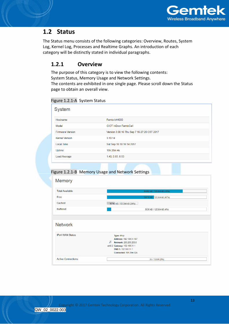
1.2.1 Overview The purpose of this category is to view the following contents: System Status, Memory Usage and Network Settings. The contents are exhibited in one single page. Please scroll down the Status page to obtain an overall view. Figure 1.2.1-A System Status
Figure 1.2.1-B Memory Usage and Network Settings

14 Copyright © 2017 Gemtek Technology Corporation. All Rights Reserved
QW_02_0022.003
Figure 1.2.1-C DHCP Leases and Wireless Status
An “AUTO REFRESH ON/OFF” button is lodged on the top right of the panel. This function enables the status data to be refreshed every 5 seconds. Status will auto refresh in 5 secs if “Auto Refresh ON” button is on. Figure 1.2.1-D Status

15 Copyright © 2017 Gemtek Technology Corporation. All Rights Reserved
QW_02_0022.003
Click “AUTO REFRESH ON/OFF” button to enable/ disable auto refresh. Figure 1.2.1-E Status
1.2.2 Routes The purpose of this category is to view the ARP table and active IPv4 routes information. Figure 1.2.2-A ARP table and Active IPv4 Routes

16 Copyright © 2017 Gemtek Technology Corporation. All Rights Reserved
QW_02_0022.003
1.2.3 System Log This category is to view system log information. Figure 1.2.3-A System Log
1.2.4 Kernel log This category is to view kernel log information. Figure 1.2.4-A Kernel Log
17 Copyright © 2017 Gemtek Technology Corporation. All Rights Reserved
QW_02_0022.003
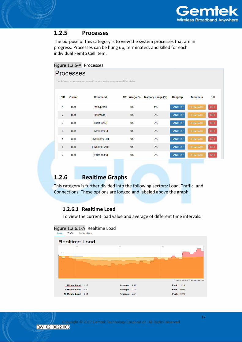
1.2.5 Processes The purpose of this category is to view the system processes that are in progress. Processes can be hung up, terminated, and killed for each individual Femto Cell item. Figure 1.2.5-A Processes
1.2.6 Realtime Graphs This category is further divided into the following sectors: Load, Traffic, and Connections. These options are lodged and labeled above the graph.
1.2.6.1 Realtime Load To view the current load value and average of different time intervals.
Figure 1.2.6.1-A Realtime Load

18 Copyright © 2017 Gemtek Technology Corporation. All Rights Reserved
QW_02_0022.003
1.2.6.2 Realtime Traffic To view the network traffic of each interface.
Figure 1.2.6.2-A Realtime Traffic
1.2.6.3 Realtime Connections To view the currently active network connections.
Figure 1.2.6.3-A Realtime Connections
19 Copyright © 2017 Gemtek Technology Corporation. All Rights Reserved
QW_02_0022.003
1.3 GIoT The GIoT menu consists of the following categories: Status, Provision, Configuration, Channel Scan and GPS MAP.
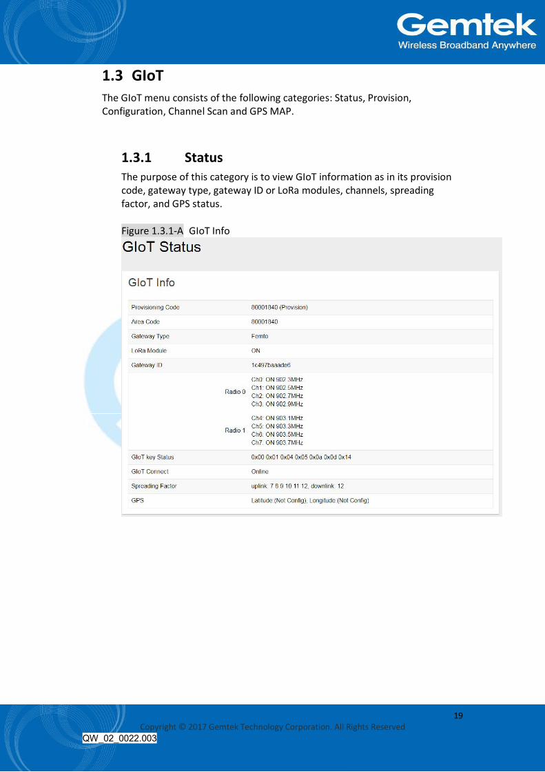
1.3.1 Status The purpose of this category is to view GIoT information as in its provision code, gateway type, gateway ID or LoRa modules, channels, spreading factor, and GPS status. Figure 1.3.1-A GIoT Info

20 Copyright © 2017 Gemtek Technology Corporation. All Rights Reserved
QW_02_0022.003
1.3.2 Provision GIoT provision code can be setup on this page. Figure 1.3.2-A Provision Code
1.3.3 Configuration Click “PERFORM RESTART” button to restart LoRa server. The latitude and longitude coordinates can be manually embedded in this page. Click “SAVE LOCATION” button after inserting the coordinates or click “SELECT ON MAP” button to be redirected to the map in GPS Settings. Users can select Normal-AP, Repeater-AP and Repeater on LoRa Configurations. Figure 1.3.3-A GIoT Management

21 Copyright © 2017 Gemtek Technology Corporation. All Rights Reserved
QW_02_0022.003
1.3.4 Channel Scan To scan LoRa channel based on ISM regulation and export the result after the scan is completed. Figure 1.3.4-A Channel Scan
1.3.5 GPS MAP To setup the GPS location, simply input your address location in the “Location” text field above the map or pinpoint your location on the map by dragging the red marker to the correct spot. Once the location is confirmed, the system will verify and apply the new Latitude/Longitude coordinates into its GPS setting. Figure 1.3.5-A GPS Setting
22 Copyright © 2017 Gemtek Technology Corporation. All Rights Reserved
QW_02_0022.003
1.4 System The System menu consists of the following categories: System, Administration, Backup, System Firmware and Reboot. Introduction and input procedures for each category are described in the following paragraphs.
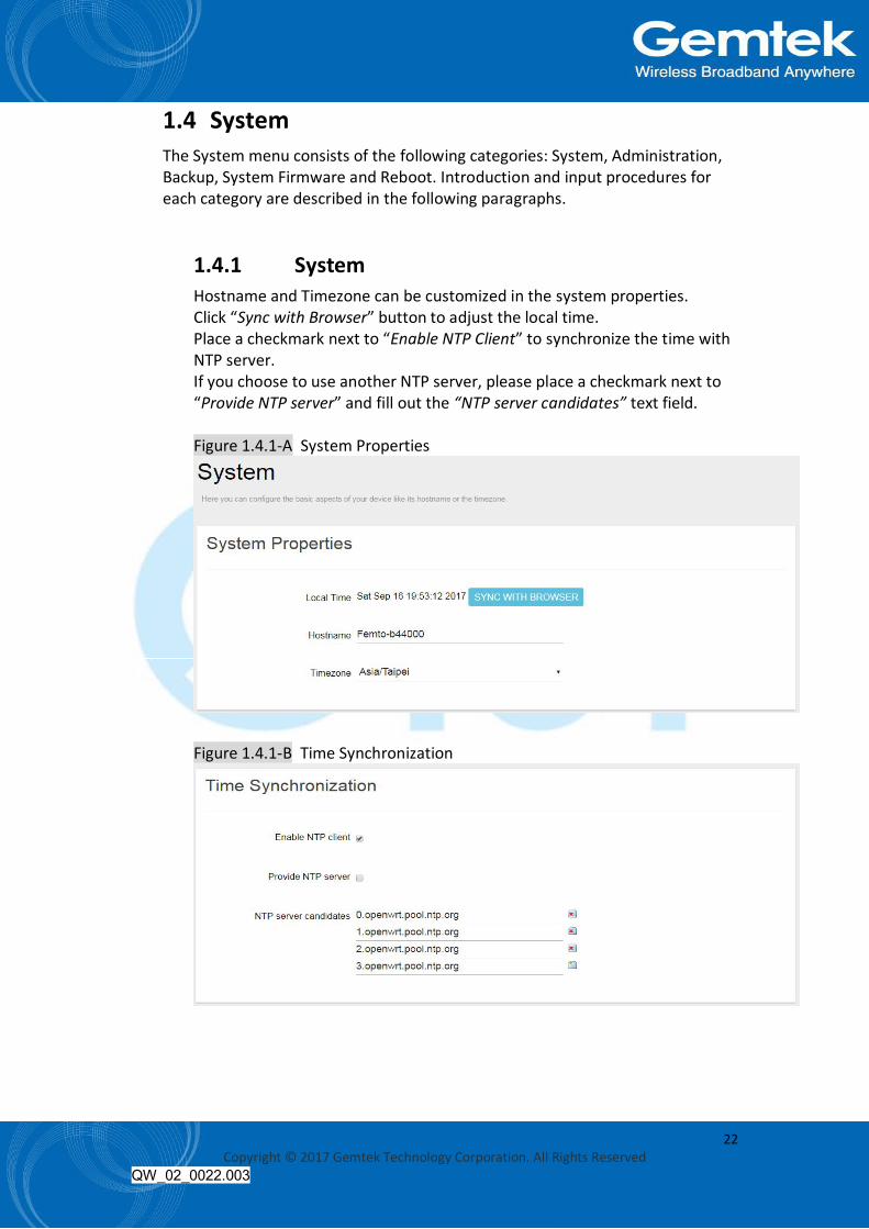
1.4.1 System Hostname and Timezone can be customized in the system properties. Click “Sync with Browser” button to adjust the local time. Place a checkmark next to “Enable NTP Client” to synchronize the time with NTP server. If you choose to use another NTP server, please place a checkmark next to “Provide NTP server” and fill out the “NTP server candidates” text field. Figure 1.4.1-A System Properties
Figure 1.4.1-B Time Synchronization

23 Copyright © 2017 Gemtek Technology Corporation. All Rights Reserved
QW_02_0022.003
1.4.2 Administration Femto login password can be configured in this page. Figure 1.4.2-A Router Password
1.4.3 Backup Femto configuration can restore and reset to default on this page. Click “GENERATE ARCHIVE” button to download the configuration file with the current gateway settings. Note: LoRa configuration cannot be restored and reset to default on this page. Figure 1.4.3-A Backup/Restore
Click “PERFORM RESET” button to reset the firmware to its initial state. Please note that the LoRa provision settings will NOT be reset by this action.

24 Copyright © 2017 Gemtek Technology Corporation. All Rights Reserved
QW_02_0022.003
Figure 1.4.3-B Backup/Restore
Choose the most recent backup file and click “UPLOAD ARCHIVE” to restore the configuration file.
1.4.4 System Firmware Click “CHECK NEW FIRMWARE” button to search the OTA server for the latest version of the new system firmware. Once a new system firmware version is detected on the OTA server, click “UPGRADE NOW” button to upgrade the newest system firmware from OTA server. Figure 1.4.4-A System Firmware

25 Copyright © 2017 Gemtek Technology Corporation. All Rights Reserved
QW_02_0022.003
1.4.5 Reboot Click “PERFORM REBOOT” to reboot Femto. Figure 1.4.5-A Reboot
1.5 Network The System menu consists of the following categories: WAN, Wireless, LAN, DHCP, Static Routes and Diagnostics. Introduction and input procedures for each category are described in the following paragraphs.
1.5.1 WAN The purpose of this category is to view current WAN settings. This category is further divided into three sectors: Ethernet Wan, 3G/4G LTE and Wireless Extender. These individual options are lodged and labeled above the main content panel. Figure 1.5.1-A WAN
1.5.1.1 Ethernet WAN This page is to setup the connection type in terms of Static IP, DHCP client or PPPoE. The three different options can be selected in the drop-down menu in “Wan Type”. Please fill in the respective fields exhibited under each selection. Please make sure the Ethernet cable is connected to a WAN port.

26 Copyright © 2017 Gemtek Technology Corporation. All Rights Reserved
QW_02_0022.003
Figure 1.5.1.1-A Static IP
Figure 1.5.1.1-B DHCP Client
Figure 1.5.1.1-C PPPoE

27 Copyright © 2017 Gemtek Technology Corporation. All Rights Reserved
QW_02_0022.003
1.5.1.2 3G/4G LTE This page is to setup required information. Note: Make sure the SIM card is installed.
Figure 1.5.1.2-A 3G/4G LTE
1.5.1.3 Wireless Extender This page is to setup the Wireless Extender Mode for WAN connection. To activate the extended wireless connection, please select “Enable” from the Extender mode drop-down menu. Click the “SCAN” button to obtain the list of available Access Points within your surrounding vicinity.
Figure 1.5.1.3-A Wireless Extender

28 Copyright © 2017 Gemtek Technology Corporation. All Rights Reserved
QW_02_0022.003
1.5.2 Wireless 2.4G Interface Configuration to setup 2.4G Wireless. SSID, Encryption Type, and Channels can be lodged within this sector. Figure 1.5.2-A Wireless Setting
1.5.3 LAN LAN IP can be setup in this page. Figure 1.5.3-A LAN
1.5.4 DHCP You can manage detailed DHCP server settings, which include First leased address, the allowed Number of leased addresses and Lease time. Information on Active Leases can be viewed at the bottom of this page.

29 Copyright © 2017 Gemtek Technology Corporation. All Rights Reserved
QW_02_0022.003
Figure 1.5.4-A DHCP
1.5.5 Static Routes Static routes can be established by clicking the “ADD” button to enter proper settings. Click “Delete” to erase the entry. Always click the “SAVE” button to apply your settings. Figure 1.5.5-A Static Routes

30 Copyright © 2017 Gemtek Technology Corporation. All Rights Reserved
QW_02_0022.003
1.5.6 Diagnostic Diagnostics is divided into three parts on the same page: PING, TRACEROUTE and NSLOOKUP. Please see the following for input guidelines.
1.5.6.1 PING Input a specific IP address in the text field above “PING”. Click the “PING” button to ping the IP you have specified.
Figure 1.5.6.1-A PING
1.5.6.2 TRACEROUTE Input a specific URL or IP address above “TRACEROUTE”. Click the “TRACEROUTE” button to trace the URL or IP address you have specified.

31 Copyright © 2017 Gemtek Technology Corporation. All Rights Reserved
QW_02_0022.003
Figure 1.5.6.2-A TRACEROUTE
1.5.6.3 NSLOOKUP Input a specific URL or IP address above “NSLOOKUP”. Click the “NSLOOKUP” button to view the DNS server of the URL or IP address you have specified.
Figure 1.5.6.3-A NSLOOKUP

32 Copyright © 2017 Gemtek Technology Corporation. All Rights Reserved
QW_02_0022.003
2. LoRaWAN mode
2.1 Open Admin GUI Connect to Femto Cell via wifi (SSID: AP-last 6 digits of mac address) Access Femto Cell WebUI via IP address “192.168.55.1”. Default username is “admin” and password is "admin“. Figure 2.1-A

33 Copyright © 2017 Gemtek Technology Corporation. All Rights Reserved
QW_02_0022.003
2.2 Status The Status menu consists of the following categories: Overview, Routes, System Log, Kernel Log, Processes and Realtime Graphs. An introduction of each category will be distinctly stated in individual paragraphs.
2.2.1 Overview The purpose of this category is to view the following contents: System Status, Memory Usage and Network Settings. The contents are exhibited in one single page. Please scroll down the Status page to obtain an overall view. Figure 2.2.1-A System Status
Figure 2.2.1-B Memory Usage and Network Settings

34 Copyright © 2017 Gemtek Technology Corporation. All Rights Reserved
QW_02_0022.003
Figure 2.2.1-C DHCP Leases and Wireless Status
An “AUTO REFRESH ON/OFF” button is lodged on the top right of the panel. This function enables the status data to be refreshed every 5 seconds. Status will auto refresh in 5 secs if “Auto Refresh ON” button is on. Figure 2.2.1-D Status

35 Copyright © 2017 Gemtek Technology Corporation. All Rights Reserved
QW_02_0022.003
Click “AUTO REFRESH ON/OFF” button to enable/ disable auto refresh. Figure 2.2.1-E Status
2.2.2 Routes The purpose of this category is to view the ARP table and active IPv4 routes information. Figure 2.2.2-A ARP table and Active IPv4 Routes

36 Copyright © 2017 Gemtek Technology Corporation. All Rights Reserved
QW_02_0022.003
2.2.3 System Log This category is to view system log information. Figure 2.2.3-A System Log
2.2.4 Kernel log This category is to view kernel log information. Figure 2.2.4-A Kernel Log

37 Copyright © 2017 Gemtek Technology Corporation. All Rights Reserved
QW_02_0022.003
2.2.5 Processes The purpose of this category is to view the system processes that are in progress. Processes can be hung up, terminated, and killed for each individual Femto Cell item. Figure 2.2.5-A Processes
2.2.6 Realtime Graphs This category is further divided into the following sectors: Load, Traffic, and Connections. These options are lodged and labeled above the graph.
2.2.6.1 Realtime Load To view the current load value and average of different time intervals.
Figure 2.2.6.1-A Realtime Load

38 Copyright © 2017 Gemtek Technology Corporation. All Rights Reserved
QW_02_0022.003
2.2.6.2 Realtime Traffic To view the network traffic of each interface.
Figure 2.2.6.2-A Realtime Traffic
2.2.6.3 Realtime Connections To view the currently active network connections.
Figure 2.2.6.3-A Realtime Connections

39 Copyright © 2017 Gemtek Technology Corporation. All Rights Reserved
QW_02_0022.003
2.3 System The System menu consists of the following categories: System, Administration, Backup, System Firmware and Reboot. Introduction and input procedures for each category are described in the following paragraphs.
2.3.1 System Hostname and Timezone can be customized in the system properties. Click “Sync with Browser” button to adjust the local time. Place a checkmark next to “Enable NTP Client” to synchronize the time with NTP server. If you choose to use another NTP server, please place a checkmark next to “Provide NTP server” and fill out the “NTP server candidates” text field. Figure 2.3.1-A System Properties
Figure 2.3.1-B Time Synchronization
40 Copyright © 2017 Gemtek Technology Corporation. All Rights Reserved
QW_02_0022.003
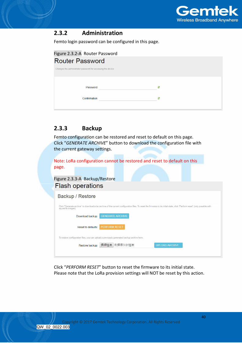
2.3.2 Administration Femto login password can be configured in this page. Figure 2.3.2-A Router Password
2.3.3 Backup Femto configuration can be restored and reset to default on this page. Click “GENERATE ARCHIVE” button to download the configuration file with the current gateway settings. Note: LoRa configuration cannot be restored and reset to default on this page. Figure 2.3.3-A Backup/Restore
Click “PERFORM RESET” button to reset the firmware to its initial state. Please note that the LoRa provision settings will NOT be reset by this action.

41 Copyright © 2017 Gemtek Technology Corporation. All Rights Reserved
QW_02_0022.003
Figure 2.3.3-B Backup/Restore
Choose the most recent backup file and click “UPLOAD ARCHIVE” to restore the configuration file.
2.3.4 System Firmware Click “CHECK NEW FIRMWARE” button to search the OTA server for the latest version of the new system firmware. Once a new system firmware version is detected on the OTA server, click “UPGRADE NOW” button to upgrade the newest system firmware from OTA server. Figure 2.3.4-A System Firmware

42 Copyright © 2017 Gemtek Technology Corporation. All Rights Reserved
QW_02_0022.003
2.3.5 Reboot Click “PERFORM REBOOT” to reboot Femto. Figure 2.3.5-A Reboot
2.4 GIoT The GIoT menu consists of the following categories: Status, Provision, Configuration, Network Server, Network Server Log, Channel Scan and GPS MAP.
2.4.1 Status The purpose of this category is to view GIoT information as in its Provision Code, Gateway Type, Gateway ID or LoRa Modules, Channels, Spreading Factor, and GPS Status. Figure 2.4.1-A GIoT Info

43 Copyright © 2017 Gemtek Technology Corporation. All Rights Reserved
QW_02_0022.003
2.4.2 Provision GIoT provision code can be setup on this page. Figure 2.4.2-A Provision Code
2.4.3 Configuration Click “PERFORM RESTART” button to restart LoRa server. The latitude and longitude coordinates can be manually embedded in this page. Click “SAVE LOCATION” button after inserting the coordinates or click “SELECT ON MAP” button to be redirected to the map in GPS Settings. Users can select Normal-AP, Repeater-AP and Repeater on LoRa Configurations. Figure 2.4.3-A GIoT Management

44 Copyright © 2017 Gemtek Technology Corporation. All Rights Reserved
QW_02_0022.003
2.4.4 Network Server The user can configure Network Server settings on this page. The Femto Cell can connect to the broker via MQTTS or MQTT. Definitions for Cloud Protocol Settings are listed as follows: Protocol: Displays the protocol that is used to connect to the lora data center. Hostname: The IP/domain name address of where the cloud server is located. Username: The username for the cloud server. Password: The password for the cloud server. Publish topic: The publishing topic of the broker established for downlink. (read only) Subscribe topic: The subscription topic of the broker established for uplink. (read only) Downlink ACK: The subscription topic of the broker established for downlink ack. (read only) Port: Displays the port number that is being used. (read only) Figure 2.4.4-A Network Server
2.4.5 Network Server Log Displays the log that is connected to the broker. Figure 2.4.5-A Network Server Log

45 Copyright © 2017 Gemtek Technology Corporation. All Rights Reserved
QW_02_0022.003
2.4.6 Channel Scan To scan LoRa channel based on ISM regulation and export the result after the scan is completed. Figure 2.4.6-A Channel Scan
2.4.7 GPS MAP To setup the GPS location, simply input your address location in the “Location” text field above the map or pinpoint your location on the map by dragging the red marker to the correct spot. Once the location is confirmed, the system will verify and apply the new Latitude/Longitude coordinates into its GPS setting.
Figure 2.4.7-A GPS Setting

46 Copyright © 2017 Gemtek Technology Corporation. All Rights Reserved
QW_02_0022.003
2.5 LoraWAN The LoraWAN menu consists of the following categories: OTAA Status, Node Parameters, OTAA and ABP.
2.5.1 OTAA Status The purpose of this category is to view the process status of a node joining Network Server via OTAA, which include DevAddr, Device EUI, App EUI, OTAA Group Index and Latest Update Time. Figure 2.5.1-A OTAA Status
Click “REFRESH”to renew OTAA Status information. When there are over 20 OTAA Status entries on the page, users can click on the page number on the upper-right corner to move on to the next page. Definitions for OTAA Status Fields are listed as follows: DevAddr: The device address of the node assigned by the network server. Device EUI: The unique device EUI of the node. App EUI: The unique app EUI of the node. Group Index: The unique index of the OTAA EUID group. Latest Update Time: The last time an uplink data was sent (sync per hour)
2.5.2 Node Parameters The purpose of this category is to view node parameters, which include DevAddr, Rx1DrOffset, Rx2DataRate, Delay, Rx2Freq and LastDownMsgSeqNo. Figure 2.5.2-A Node Parameters

47 Copyright © 2017 Gemtek Technology Corporation. All Rights Reserved
QW_02_0022.003
Users can input a device address in the blank field and click “APPLY” to filter, or click “CLEAR” to cancel filter. Click “REFRESH” to renew Node Parameters information. When there are over 20 Node Parameters entries on the page, users can click on the page number on the upper-right corner to move on to the next page. Users can also select a Node Parameter entry and click “DELETE” to delete its information.
Definitions for Node Parameters Fields are listed as follows: DevAddr: The unique device address of node. Rx1DrOffset: The downlink data rate offset of Rx1. Rx2DataRate: The downlink data rate of Rx2. Delay: The delay between TX and RX. Rx2Freq: The downlink frequency of RX2. LastDownMsgSeqNo: The number of downlink data sent.
2.5.3 OTAA The purpose of this category is to view and configure OTAA rules. Click “ADD” button to enter OTAA add page and input Group Index, AppEUI Start, AppEUI Counts , DevEUI Start , DevEUI Counts , Devaddr Start, Devaddr Counts, Appkey and Aging Out Time, then click “SAVE” to create an OTAA rule. User will leave OTAA Add page after clicking “CANCEL”. Definitions for OTAA Fields are listed as follows: Group Index: The unique index of the OTAA EUID group. AppEUI Start: The start number of AppEUI. App Counts: The number of AppEUI in this Group. DevEUI Start: The start number of DevEUI. DevEUI Counts: The number of DevEUI in this Group. DevAddr Start: The start number of DevAddr. DevAddr Counts: The number of DevAddr in this Group. AppKey: Appkey for OTAA join request. Aging Out Time(Minutes): If the Node hasn't sent an uplink message within the aging out time limit, the allocated OTAA DevAddr will become expired and released. Note: The Aging Out Time must be at least 60 minutes.

48 Copyright © 2017 Gemtek Technology Corporation. All Rights Reserved
QW_02_0022.003
Figure 2.5.3-A OTAA Add
To delete entries, select one or more OTAA rule entries and click “DELETE” button. Figure 2.5.3-B OTAA Delete
To edit an entry, select a rule entry and click “EDIT” button to proceed. Edit AppEUI Start, AppEUI Counts , DevEUI Start , DevEUI Counts , Devaddr Start, Devaddr Counts, Appkey and Aging Out Time then click “SAVE” to edit the OTAA rule. User will leave OTAA Edit page after clicking “CANCEL”.

49 Copyright © 2017 Gemtek Technology Corporation. All Rights Reserved
QW_02_0022.003
Figure 2.5.3-C OTAA Edit
2.5.4 ABP The main function of this feature is to add/delete/edit ABP rule entries on this page. The ABP menu consists of the following categories: INDIVIDUAL and NETID GROUP.
2.5.5 INDIVIDUAL Click “INDIVIDUAL” button to enter the INDIVIDUAL function page. Figure 2.5.5-A INDIVIDUAL

50 Copyright © 2017 Gemtek Technology Corporation. All Rights Reserved
QW_02_0022.003
Click “ADD” button to enter ABP add page and input DevAddr, NwkSKey and AppSKey, then click “SAVE” to create an ABP (INDIVIDUAL) rule. User will leave ABP Add page after clicking “CANCEL”. Definitions for ABP (INDIVIDUAL) Fields are listed as follows: DevAddr: The unique device address of the node. NwkSKey: The network session key. AppSKey: The app session key. Figure 2.5.5-B INDIVIDUAL Add
To delete entries, select one or more ABP (INDIVIDUAL) rule entries and click “DELETE” button. Figure 2.5.5-C INDIVIDUAL Delete

51 Copyright © 2017 Gemtek Technology Corporation. All Rights Reserved
QW_02_0022.003
To edit an entry, select a rule entry and click “EDIT” button to proceed. Edit NwkSKey and AppSKey, then click “SAVE” to edit the ABP (INDIVIDUAL). User will leave ABP Edit page after clicking “CANCEL”. Figure 2.5.5-D INDIVIDUAL Edit
2.5.5.1 NETID GROUP Click “NETID GROUP” button to enter the NETID GROUP function page.
Figure 2.5.5.1-A NETID GROUP

52 Copyright © 2017 Gemtek Technology Corporation. All Rights Reserved
QW_02_0022.003
Click “ADD” button to enter ABP add page and input NwkID, NwkAddr Start, NwkAddr Total Number ,NwkSKey and AppSKey, then click “SAVE” to create an ABP (NETID GROUP) rule. User will leave ABP add page after clicking “CANCEL”. Definitions for ABP (NETID GROUP) Fields are listed as follows: NwkID: The unique NETID of the ABP group. NwkAddr Start: The start number of ABP device address in the Group. NwkAddr Total Number: The number of ABP device addresses in this Group. NwkSKey: The network session key in the Group. AppSKey: The app session key in the Group.
Figure 2.5.5.1-B NETID GROUP Add
To delete entries, select one or more ABP (NETID GROUP) rule entries and click “DELETE” button.
Figure 2.5.5.1-C NETID GROUP Delete

53 Copyright © 2017 Gemtek Technology Corporation. All Rights Reserved
QW_02_0022.003
To edit an entry, select a rule entry and click “EDIT” button to proceed. Edit NwkAddr Start, NwkAddr ,NwkSKey and AppSKey, then click “SAVE” to edit the ABP (NETID GROUP). User will leave ABP edit page after clicking “CANCEL”.
Figure 2.5.5.1-D NETID GROUP Edit
2.6 Network The System menu consists of the following categories: WAN, Wireless, LAN, DHCP, Static Routes and Diagnostics. Introduction and input procedures for each category are described in the following paragraphs.
2.6.1 WAN The purpose of this category is to view current WAN settings. This category is further divided into three sectors: Ethernet Wan, 3G/4G LTE and Wireless Extender. These individual options are lodged and labeled above the main content panel. Figure 2.6.1-A WAN

54 Copyright © 2017 Gemtek Technology Corporation. All Rights Reserved
QW_02_0022.003
2.6.1.1 Ethernet WAN This page is to setup the connection type in terms of Static IP, DHCP client or PPPoE. The three different options can be selected in the drop-down menu in “wantype”. Please fill in the respective fields exhibited under each selection. Please make sure the Ethernet cable is connected to a WAN port.
Figure 2.6.1.1-A Static IP
Figure 2.6.1.1-B DHCP Client
Figure 2.6.1.1-C PPPoE

55 Copyright © 2017 Gemtek Technology Corporation. All Rights Reserved
QW_02_0022.003
2.6.1.2 3G/4G LTE This page is to setup required information. Note: Make sure the SIM card is installed.
Figure 2.6.1.2-A 3G/4G LTE
2.6.1.3 Wireless Extender This page is to setup the Wireless Extender Mode for WAN connection. To activate the extended wireless connection, please select “Enable” from the Extender mode drop-down menu. Click the “SCAN” button to obtain the list of available Access Points within your surrounding vicinity.
Figure 2.6.1.3-A Wireless Extender

56 Copyright © 2017 Gemtek Technology Corporation. All Rights Reserved
QW_02_0022.003
2.6.2 Wireless 2.4G Interface Configuration to setup 2.4G wireless. SSID, Encryption Type, and Channels can be lodged within this sector. Figure 2.6.2-A Wireless Setting
2.6.3 LAN LAN IP can be setup in this page. Figure 2.6.3-A LAN

57 Copyright © 2017 Gemtek Technology Corporation. All Rights Reserved
QW_02_0022.003
2.6.4 DHCP You can manage detailed DHCP server settings, which include First leased address, the allowed Number of leased addresses and Lease time. Information on Active Leases can be viewed at the bottom of this page. Figure 2.6.4-A DHCP
2.6.5 Static Routes Static routes can be established by clicking the “ADD” button to enter proper settings. Click “Delete” to erase the entry. Always click the “SAVE” button to apply your settings. Figure 2.6.5-A Static Routes

58 Copyright © 2017 Gemtek Technology Corporation. All Rights Reserved
QW_02_0022.003
2.6.6 Diagnostic Diagnostics is divided into three parts on the same page: PING, TRACEROUTE and NSLOOKUP. Please see the following for input guidelines.
2.6.6.1 PING Input a specific IP address in the text field above “PING”. Click the “PING” button to ping the IP you have specified.
Figure 2.6.6.1-A PING
2.6.6.2 TRACEROUTE Input a specific URL or IP address above “TRACEROUTE”. Click the “TRACEROUTE” button to trace the URL or IP address you have specified.
Figure 2.6.6.2-A TRACEROUTE

59 Copyright © 2017 Gemtek Technology Corporation. All Rights Reserved
QW_02_0022.003
2.6.6.3 NSLOOKUP Input a specific URL or IP address above “NSLOOKUP”. Click the “NSLOOKUP” button to view the DNS server of the URL or IP address you have specified.
Figure 2.6.6.3-A NSLOOKUP

60 Copyright © 2017 Gemtek Technology Corporation. All Rights Reserved
QW_02_0022.003
3. Education mode
3.1 Open Admin GUI Connect to Femto Cell via wifi (SSID: AP-last 6 digits of mac address) Access Femto Cell WebUI via IP address “192.168.55.1”. Default username is “admin” and password is "admin“. Figure 3.1-A

61 Copyright © 2017 Gemtek Technology Corporation. All Rights Reserved
QW_02_0022.003
3.2 Status The Status menu consists of the following categories: Overview, Routes, System Log, Kernel Log, Processes and Realtime Graphs. An introduction of each category will be distinctly stated in individual paragraphs.
3.2.1 Overview The purpose of this category is to view the following contents: System Status, Memory Usage and Network Settings. The contents are exhibited in one single page. Please scroll down the Status page to obtain an overall view. Figure 3.2.1-A System Status
Figure 3.2.1-B Memory Usage and Network Settings

62 Copyright © 2017 Gemtek Technology Corporation. All Rights Reserved
QW_02_0022.003
Figure 3.2.1-C DHCP Leases and Wireless Status
An “AUTO REFRESH ON/OFF” button is lodged on the top right of the panel. This function enables the status data to be refreshed every 5 seconds. The status will auto refresh in 5 secs if “Auto Refresh ON” button is on. Figure 3.2.1-D Status

63 Copyright © 2017 Gemtek Technology Corporation. All Rights Reserved
QW_02_0022.003
Click “AUTO REFRESH ON/OFF” button to enable/ disable auto refresh. Figure 3.2.1-E Status
3.2.2 Routes The purpose of this category is to view the ARP table and active IPv4 routes information. Figure 3.2.2-A ARP table and Active IPv4 Routes

64 Copyright © 2017 Gemtek Technology Corporation. All Rights Reserved
QW_02_0022.003
3.2.3 System Log This category is to view System Log information. Figure 3.2.3-A System Log
3.2.4 Kernel Log This category is to view Kernel Log information. Figure 3.2.4-A Kernel Log

65 Copyright © 2017 Gemtek Technology Corporation. All Rights Reserved
QW_02_0022.003
3.2.5 Processes The purpose of this category is to view the system processes that are in progress. Processes can be hung up, terminated, and killed for each individual Femto Cell item. Figure 3.2.5-A Processes
3.2.6 Realtime Graphs This category is further divided into the following sectors: Load, Traffic, and Connections. These options are lodged and labeled above the graph.
3.2.6.1 Realtime Load To view the current load value and average of different time intervals.
Figure 3.2.6.1-A Realtime Load

66 Copyright © 2017 Gemtek Technology Corporation. All Rights Reserved
QW_02_0022.003
3.2.6.2 Realtime Traffic To view the network traffic of each interface.
Figure 3.2.6.2-A Realtime Traffic
3.2.6.3 Realtime Connections To view the currently active network connections.
Figure 3.2.6.3-A Realtime Connections

67 Copyright © 2017 Gemtek Technology Corporation. All Rights Reserved
QW_02_0022.003
3.3 System The System menu consists of the following categories: System, Administration, Backup, System Firmware and Reboot. Introduction and input procedures for each category are described in the following paragraphs.
3.3.1 System Hostname and Timezone can be customized in the system properties. Click “Sync with Browser” button to adjust the local time. Place a checkmark next to “Enable NTP Client” to synchronize the time with NTP server. If you choose to use another NTP server, please place a checkmark next to “Provide NTP server” and fill out the “NTP server candidates” text field. Figure 3.3.1-A System Properties
Figure 3.3.1-B Time Synchronization

68 Copyright © 2017 Gemtek Technology Corporation. All Rights Reserved
QW_02_0022.003
3.3.2 Administration Femto login password can be configured in this page. Figure 3.3.2-A Router Password
3.3.3 Backup Femto configuration can be restored and reset to default on this page. Click “GENERATE ARCHIVE” button to download the configuration file with the current gateway settings. Note: LoRa configuration cannot be restored and reset to default on this page. Figure 3.3.3-A Backup/Restore

69 Copyright © 2017 Gemtek Technology Corporation. All Rights Reserved
QW_02_0022.003
Click “PERFORM RESET” button to reset the firmware to its initial state. Please note that the LoRa provision settings will NOT be reset by this action. Figure 3.3.3-B Backup/Restore
Choose the most recent backup file and click “UPLOAD ARCHIVE” to restore the configuration file.
3.3.4 Reboot Click “PERFORM REBOOT” to reboot Femto. Figure 3.3.4-A Reboot

70 Copyright © 2017 Gemtek Technology Corporation. All Rights Reserved
QW_02_0022.003
3.4 GIoT The GIoT menu consists of the following categories: Status, Provision, Configuration, Networl Server, Network Server Log, Channel Scan, Channel Setting and GPS MAP.
3.4.1 Status The purpose of this category is to view GIoT information as in its provision code, gateway type, gateway ID or LoRa modules, channels, spreading factor, and GPS status. Figure 3.4.1-A GIoT Info
3.4.2 Provision GIoT provision code can be setup on this page. Figure 3.4.2-A Provision Code

71 Copyright © 2017 Gemtek Technology Corporation. All Rights Reserved
QW_02_0022.003
3.4.3 Configuration Click “PERFORM RESTART” button to restart LoRa server. The latitude and longitude coordinates can be manually embedded in this page. Click “SAVE LOCATION” button after inserting the coordinates or click “SELECT ON MAP” button to be redirected to the map in GPS Settings. User can select Normal-AP, Repeater-AP and Repeater for LoRa Configurations. Figure 3.4.3-A GIoT Management
3.4.4 Network Server The user can configure Network Server settings on this page. The Femto Cell can connect to the broker via MQTTS or MQTT. Definitions for Cloud Protocol Settings are listed as follows: Protocol: Displays the protocol that is used to connect to the lora data center. Hostname: The IP/domain name address of where the cloud server is located. Username: The username for the cloud server. Password: The password for the cloud server. Publish topic: The publishing topic of the broker set for downlink. (read only) Subscribe topic: The subscription topic of the broker set for uplink. (read only)

72 Copyright © 2017 Gemtek Technology Corporation. All Rights Reserved
QW_02_0022.003
Downlink ACK: The subscription topic of the broker set for downlink ack. (read only) Port: Displays the port number that is being used. (read only) Figure 3.4.4-A Network Server
3.4.5 Network Server Log Displays the log that is connected to the broker. Figure 3.4.5-A Network Server Log

73 Copyright © 2017 Gemtek Technology Corporation. All Rights Reserved
QW_02_0022.003
3.4.6 Channel Scan To scan LoRa channel based on ISM regulation and export the result after the scan is completed. Figure 3.4.6-A Channel Scan
3.4.7 Channel Setting To setup the Center Frequency for LoRa on this page. Figure 3.4.7‑A Channel Setting

74 Copyright © 2017 Gemtek Technology Corporation. All Rights Reserved
QW_02_0022.003
3.4.8 GPS MAP To setup the GPS location, simply input your address location in the “Location” text field above the map or pinpoint your location on the map by dragging the red marker to the correct spot. Once the location is confirmed, the system will verify and apply the new Latitude/Longitude coordinates into its GPS setting. Figure 3.4.8-A GPS Setting
3.5 LoraWAN The LoraWAN menu consists of the following categories: OTAA Status, Node Parameters, OTAA and ABP.
3.5.1 OTAA Status The purpose of this category is to view the process status of a node joining Network Server via OTAA, include DevAddr, Device EUI, App EUI, OTAA Group Index and Latest Update Time. Figure 3.5.1-A OTAA Status

75 Copyright © 2017 Gemtek Technology Corporation. All Rights Reserved
QW_02_0022.003
Click “REFRESH” to renew OTAA Status information. When there are over 20 OTAA Status entries on the page, users can click on the page number on the upper-right corner to move on to the next page. Definitions for OTAA Status Fields are listed as follows: DevAddr: The device address of the node assigned by the network server Device EUI: The unique device EUI of the node. App EUI: The unique app EUI of the node. OTAA Group Index: The unique index of the OTAA EUID group. Latest Update Time: The last time an uplink data was sent (sync per hour)
3.5.2 Node Parameters The purpose of this category is to view node parameters, which include DevAddr, Rx1DrOffset, Rx2DataRate, Delay, Rx2Freq and LastDownMsgSeqNo. Figure 3.5.2-A Node Parameters
Users can input a device address in the blank field and click “APPLY” to filter, or click “CLEAR” to cancel filter. Click “REFRESH” to renew Node Parameters information. When there are over 20 Node Parameters entries on the page, users can click on the page number on the upper-right corner to move on to the next page. Users can also select a Node Parameter entry and click “DELETE” to delete its information. Definitions for Node Parameters Fields are listed as follows: DevAddr: The unique device address of node. Rx1DrOffset: The downlink data rate offset of Rx1. Rx2DataRate: The downlink data rate of Rx2. Delay: The delay between TX and RX. Rx2Freq: The downlink frequency of RX2. LastDownMsgSeqNo: The number of downlink data sent.

76 Copyright © 2017 Gemtek Technology Corporation. All Rights Reserved
QW_02_0022.003
3.5.3 OTAA The purpose of this category is to view and configure OTAA rules. Figure 3.5.3-A OTAA
Note: Please note that there is a default OTAA rule which cannot be deleted or edited. Click “ADD” button to enter OTAA add page and input Group Index, AppEUI Start, AppEUI Counts , DevEUI Start , DevEUI Counts , Devaddr Start, Devaddr Counts, Appkey and Aging Out Time, then click “SAVE” to create an OTAA rule. User will leave OTAA Add page after clicking “CANCEL”.

77 Copyright © 2017 Gemtek Technology Corporation. All Rights Reserved
QW_02_0022.003
Definitions for OTAA Fields are listed as follows: Group Index: The unique index of the OTAA EUID group. AppEUI Start: The start number of AppEUI. App Counts: The number of AppEUI in this Group. DevEUI Start: The start number of DevEUI. DevEUI Counts: The number of DevEUI in this Group. DevAddr Start: The start number of DevAddr. DevAddr Counts: The number of DevAddr in this Group. AppKey: Appkey for OTAA join request. Aging Out Time(Minutes): If the Node hasn't sent an uplink message within the aging out time limit, the allocated OTAA DevAddr will become expired and released. Note: The Aging Out Time must be at least 60 minutes. Figure 3.5.3-B OTAA Add
To delete entries, select one or more OTAA rule entries and click “DELETE” button. Figure 3.5.3-C OTAA Delete
78 Copyright © 2017 Gemtek Technology Corporation. All Rights Reserved
QW_02_0022.003
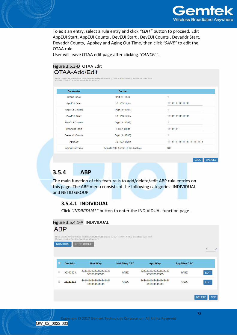
To edit an entry, select a rule entry and click “EDIT” button to proceed. Edit AppEUI Start, AppEUI Counts , DevEUI Start , DevEUI Counts , Devaddr Start, Devaddr Counts, Appkey and Aging Out Time, then click “SAVE” to edit the OTAA rule. User will leave OTAA edit page after clicking “CANCEL”. Figure 3.5.3-D OTAA Edit
3.5.4 ABP The main function of this feature is to add/delete/edit ABP rule entries on this page. The ABP menu consists of the following categories: INDIVIDUAL and NETID GROUP.
3.5.4.1 INDIVIDUAL Click “INDIVIDUAL” button to enter the INDIVIDUAL function page.
Figure 3.5.4.1-A INDIVIDUAL

79 Copyright © 2017 Gemtek Technology Corporation. All Rights Reserved
QW_02_0022.003
Click “ADD” button to enter ABP add page and input DevAddr, NwkSKey and AppSKey, then click “SAVE” to create an ABP (INDIVIDUAL) rule. User will leave ABP Add page after clicking “CANCEL”. Definitions for ABP (INDIVIDUAL) Fields are listed as follows: DevAddr: The unique device address of the node. NwkSKey: The network session key. AppSKey: The app session key.
Figure 3.5.4.1-B INDIVIDUAL Add
To delete entries, select one or more ABP (INDIVIDUAL) rule entries and click “DELETE” button.
Figure 3.5.4.1-C INDIVIDUAL Delete

80 Copyright © 2017 Gemtek Technology Corporation. All Rights Reserved
QW_02_0022.003
To edit an entry, select a rule entry and click “EDIT” button to proceed. Edit NwkSKey and AppSKey, then click “SAVE” to edit the ABP (INDIVIDUAL). User will leave ABP Edit page after clicking “CANCEL”.
Figure 3.5.4.1-D INDIVIDUAL Edit
3.5.4.2 NETID GROUP Click “NETID GROUP” button to enter the NETID GROUP function page.
Figure 3.5.4.2-A NETID GROUP
Note: Please note that there is a default ABP (NETID GROUP) rule which cannot be deleted or edited.

81 Copyright © 2017 Gemtek Technology Corporation. All Rights Reserved
QW_02_0022.003
Click “ADD” button to enter ABP add page and input NwkID, NwkAddr Start, NwkAddr Total Number ,NwkSKey and AppSKey, then click “SAVE” to create an ABP (NETID GROUP) rule. User will leave ABP Add page after clicking “CANCEL”. Definitions for ABP (NETID GROUP) Fields are listed as follows: NwkID: The unique NETID of the ABP group. NwkAddr Start: The start number of ABP device address in the Group. NwkAddr Total Number: The number of ABP device addresses in this Group. NwkSKey: The network session key in the Group. AppSKey: The app session key in the Group.
Figure 3.5.4.2-B NETID GROUP Add
To delete entries, select one or more ABP (NETID GROUP) rule entries and click “DELETE” button.
Figure 3.5.4.2-C NETID GROUP Delete

82 Copyright © 2017 Gemtek Technology Corporation. All Rights Reserved
QW_02_0022.003
To edit an entry, select a rule entry and click “EDIT” button to proceed. Edit NwkAddr Start, NwkAddr ,NwkSKey and AppSKey, then click “SAVE” to edit the ABP (NETID GROUP). User will leave ABP Edit page after clicking “CANCEL”.
Figure 3.5.4.2-D NETID GROUP Edit
3.6 Network The System menu consists of the following categories: WAN, Wireless, LAN, DHCP, Static Routes and Diagnostics. Introduction and input procedures for each category are described in the following paragraphs.
3.6.1 WAN The purpose of this category is to view current WAN settings. This category is further divided into three sectors: Ethernet Wan, 3G/4G LTE and Wireless Extender. These individual options are lodged and labeled above the main content panel. Figure 3.6.1-A WAN

83 Copyright © 2017 Gemtek Technology Corporation. All Rights Reserved
QW_02_0022.003
3.6.1.1 Ethernet WAN This page is to setup the connection type in terms of Static IP, DHCP client or PPPoE. The three different options can be selected in the drop-down menu in “wantype”. Please fill in the respective fields exhibited under each selection. Please make sure the Ethernet cable is connected to a WAN port.
Figure 3.6.1.1-A Static IP
Figure 3.6.1.1-B DHCP Client
Figure 3.6.1.1-C PPPoE

84 Copyright © 2017 Gemtek Technology Corporation. All Rights Reserved
QW_02_0022.003
3.6.1.2 3G/4G LTE This page is to setup required information. Note: Make sure the SIM card is installed.
Figure 3.6.1.2-A 3G/4G LTE
3.6.1.3 Wireless Extender This page is to setup the Wireless Extender Mode for WAN connection. To activate the extended wireless connection, please select “Enable” from the Extender mode drop-down menu. Click the “SCAN” button to obtain the list of available Access Points within your surrounding vicinity.
Figure 3.6.1.3-A Wireless Extender
85 Copyright © 2017 Gemtek Technology Corporation. All Rights Reserved
QW_02_0022.003
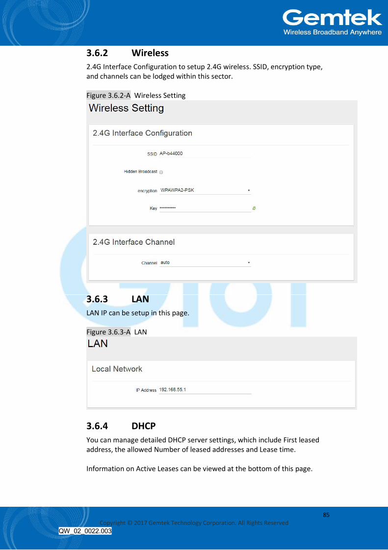
3.6.2 Wireless 2.4G Interface Configuration to setup 2.4G wireless. SSID, encryption type, and channels can be lodged within this sector. Figure 3.6.2-A Wireless Setting
3.6.3 LAN LAN IP can be setup in this page. Figure 3.6.3-A LAN
3.6.4 DHCP You can manage detailed DHCP server settings, which include First leased address, the allowed Number of leased addresses and Lease time. Information on Active Leases can be viewed at the bottom of this page.

86 Copyright © 2017 Gemtek Technology Corporation. All Rights Reserved
QW_02_0022.003
Figure 3.6.4-A DHCP
3.6.5 Static Routes Static routes can be established by clicking the “ADD” button to enter proper settings. Click “Delete” to erase the entry. Always click the “SAVE” button to apply your settings. Figure 3.6.5-A Static Routes

87 Copyright © 2017 Gemtek Technology Corporation. All Rights Reserved
QW_02_0022.003
3.6.6 Diagnostic Diagnostics is divided into three parts on the same page: PING, TRACEROUTE and NSLOOKUP. Please see the following for input guidelines.
3.6.6.1 PING Input a specific IP address in the text field above “PING”. Click the “PING” button to ping the IP you have specified.
Figure 3.6.6.1-A PING
3.6.6.2 TRACEROUTE Input a specific URL or IP address above “TRACEROUTE”. Click the “TRACEROUTE” button to trace the URL or IP address you have specified.

88 Copyright © 2017 Gemtek Technology Corporation. All Rights Reserved
QW_02_0022.003
Figure 3.6.6.2-A TRACEROUTE
3.6.6.3 NSLOOKUP Input a specific URL or IP address above “NSLOOKUP”. Click the “NSLOOKUP” button to view the DNS server of the URL or IP address you have specified.
Figure 3.6.6.3-A NSLOOKUP
89 Copyright © 2017 Gemtek Technology Corporation. All Rights Reserved
QW_02_0022.003
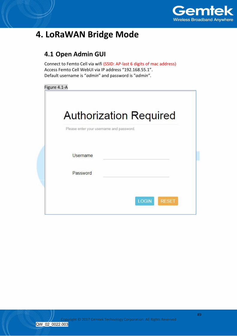
4. LoRaWAN Bridge Mode
4.1 Open Admin GUI Connect to Femto Cell via wifi (SSID: AP-last 6 digits of mac address) Access Femto Cell WebUI via IP address “192.168.55.1”. Default username is “admin” and password is "admin“. Figure 4.1-A

90 Copyright © 2017 Gemtek Technology Corporation. All Rights Reserved
QW_02_0022.003
4.2 Status The Status menu consists of the following categories: Overview, Routes, System Log, Kernel Log, Processes and Realtime Graphs. An introduction of each category will be distinctly stated in individual paragraphs.
4.2.1 Overview The purpose of this category is to view the following contents: System Status, Memory Usage and Network Settings. The contents are exhibited in one single page. Please scroll down the Status page to obtain an overall view. Figure 4.2.1-A System Status
Figure 4.2.1-B Memory Usage and Network Settings

91 Copyright © 2017 Gemtek Technology Corporation. All Rights Reserved
QW_02_0022.003
Figure 4.2.1-C DHCP Leases and Wireless Status
An “AUTO REFRESH ON/OFF” button is lodged on the top right of the panel. This function enables the status data to be refreshed every 5 seconds. Status will auto refresh in 5 secs if “Auto Refresh ON” button is on Figure 4.2.1-D Status

92 Copyright © 2017 Gemtek Technology Corporation. All Rights Reserved
QW_02_0022.003
Click “AUTO REFRESH ON/OFF” button to enable/ disable auto refresh Figure 4.2.1-E Status
4.2.2 Routes The purpose of this category is to view the ARP table and active IPv4 routes information. Figure 4.2.2-A ARP table and Active IPv4 Routes

93 Copyright © 2017 Gemtek Technology Corporation. All Rights Reserved
QW_02_0022.003
4.2.3 System Log This category is to view system log information. Figure 4.2.3-A System Log
4.2.4 Kernel log This category is to view kernel log information. Figure 4.2.4-A Kernel Log

94 Copyright © 2017 Gemtek Technology Corporation. All Rights Reserved
QW_02_0022.003
4.2.5 Processes The purpose of this category is to view the system processes that are in progress. Processes can be hung up, terminated, and killed for each individual Femto Cell item. Figure 4.2.5-A Processes
4.2.6 Realtime Graphs This category is further divided into the following sectors: Load, Traffic, and Connections. These options are lodged and labeled above the graph.
4.2.6.1 Realtime Load To view the current load value and average of different time intervals.
Figure 4.2.6.1-A Realtime Load

95 Copyright © 2017 Gemtek Technology Corporation. All Rights Reserved
QW_02_0022.003
4.2.6.2 Realtime Traffic To view the network traffic of each interface.
Figure 4.2.6.2-A Realtime Traffic
4.2.6.3 Realtime Connections To view the currently active network connections.
Figure 4.2.6.3-A Realtime Connections

96 Copyright © 2017 Gemtek Technology Corporation. All Rights Reserved
QW_02_0022.003
4.3 GIoT The GIoT menu consists of the following categories: Status, Provision, Configuration, Network Server, Network Server Log, Channel Scan and GPS MAP.
4.3.1 Status The purpose of this category is to view GIoT information, as in its Provision Code, Gateway Type, Gateway ID or LoRa modules, Channels, Spreading Factor, and GPS Status. Figure 4.3.1-A GIoT Info

97 Copyright © 2017 Gemtek Technology Corporation. All Rights Reserved
QW_02_0022.003
4.3.2 Provision GIoT provision code can be setup on this page. Figure 4.3.2-A Provision Code
4.3.3 Configuration Click “PERFORM RESTART” button to restart LoRa server. The latitude and longitude coordinates can be manually embedded in this page. Click “SAVE LOCATION” button after inserting the coordinates or click “SELECT ON MAP” button to be redirected to the map in GPS Settings. User can select Normal-AP, Repeater-AP and Repeater on LoRa Configurations.

98 Copyright © 2017 Gemtek Technology Corporation. All Rights Reserved
QW_02_0022.003
Figure 4.3.3-A GIoT Management
4.3.4 Network Server The user can configure Network Server settings on this page. The Femto Cell can connect to the broker via MQTTS or MQTT. Definitions for Cloud Protocol Settings are listed as follows: Protocol: Displays the protocol that is used to connect to the lora data center. Hostname: The IP/domain name address of where the cloud server is located. Username: The username for the cloud server. Password: The password for the cloud server. Publish topic: The publishing topic of the broker set for downlink. (read only) Subscribe topic: The subscription topic of the broker set for uplink. (read only) Downlink ACK: The subscription topic of the broker set for downlink ack. (read only) Port: Displays the port number that is being used. (read only)

99 Copyright © 2017 Gemtek Technology Corporation. All Rights Reserved
QW_02_0022.003
Figure 4.3.4-A Network Server
4.3.5 Network Server Log Displays the log that is connected to the broker. Figure 4.3.5-A Network Server Log

100 Copyright © 2017 Gemtek Technology Corporation. All Rights Reserved
QW_02_0022.003
4.3.6 Channel Scan To scan LoRa channel based on ISM regulation and export the result after the scan is completed. Figure 4.3.6-A Channel Scan
4.3.7 GPS MAP To setup the GPS location, simply input your address location in the “Location” text field above the map or pinpoint your location on the map by dragging the red marker to the correct spot. Once the location is confirmed, the system will verify and apply the new Latitude/Longitude coordinates into its GPS setting. Figure 4.3.7-A GPS Setting

101 Copyright © 2017 Gemtek Technology Corporation. All Rights Reserved
QW_02_0022.003
4.4 System The System menu consists of the following categories: System, Administration, Backup, System Firmware and Reboot. Introduction and input procedures for each category are described in the following paragraphs.
4.4.1 System Hostname and Timezone can be customized in the system properties. Click “Sync with Browser” button to adjust the local time. Place a checkmark next to “Enable NTP Client” to synchronize the time with NTP server. If you choose to use another NTP server, please place a checkmark next to “Provide NTP server” and fill out the “NTP server candidates” text field. Figure 4.4.1-A System Properties
Figure 4.4.1-B Time Synchronization

102 Copyright © 2017 Gemtek Technology Corporation. All Rights Reserved
QW_02_0022.003
4.4.2 Administration Femto login password can be configured in this page. Figure 4.4.2-A Router Password
4.4.3 Backup Femto configuration can be restored and reset to default on this page. Click “GENERATE ARCHIVE” button to download the configuration file with the current gateway settings. Note: LoRa configuration cannot restore and reset to default on this page. Figure 4.4.3-A Backup/Restore
Click “PERFORM RESET” button to reset the firmware to its initial state. Please note that the LoRa provision settings will NOT be reset by this action.

103 Copyright © 2017 Gemtek Technology Corporation. All Rights Reserved
QW_02_0022.003
Figure 4.4.3-B Backup/Restore
Choose the most recent backup file and click “UPLOAD ARCHIVE” to restore the configuration file.
4.4.4 Reboot Click “PERFORM REBOOT” to reboot Femto. Figure 4.4.4-A Reboot
4.5 Network The System menu consists of the following categories: WAN, Wireless, LAN, DHCP, Static Routes and Diagnostics. Introduction and input procedures for each category are described in the following paragraphs.
4.5.1 WAN The purpose of this category is to view current WAN settings. This category is further divided into three sectors: Ethernet Wan, 3G/4G LTE and Wireless Extender. These individual options are lodged and labeled above the main content panel.

104 Copyright © 2017 Gemtek Technology Corporation. All Rights Reserved
QW_02_0022.003
Figure 4.5.1-A WAN
4.5.1.1 Ethernet WAN This page is to setup the connection type in terms of Static IP, DHCP client or PPPoE. The three different options can be selected in the drop-down menu in “wantype”. Please fill in the respective fields exhibited under each selection. Please make sure the Ethernet cable is connected to a WAN port.
Figure 4.5.1.1-A Static IP
Figure 4.5.1.1-B DHCP Client

105 Copyright © 2017 Gemtek Technology Corporation. All Rights Reserved
QW_02_0022.003
Figure 4.5.1.1-C PPPoE
4.5.1.2 3G/4G LTE This page is to setup required information. Note: Make sure the SIM card is installed.
Figure 4.5.1.2-A 3G/4G LTE

106 Copyright © 2017 Gemtek Technology Corporation. All Rights Reserved
QW_02_0022.003
4.5.1.3 Wireless Extender This page is to setup the Wireless Extender Mode for WAN connection. To activate the extended wireless connection, please select “Enable” from the Extender mode drop-down menu. Click the “SCAN” button to obtain the list of available Access Points within your surrounding vicinity.
Figure 4.5.1.3-A Wireless Extender
4.5.2 Wireless 2.4G Interface Configuration to setup 2.4G wireless. SSID, Encryption Type, and Channels can be lodged within this sector. Figure 4.5.2-A Wireless Setting

107 Copyright © 2017 Gemtek Technology Corporation. All Rights Reserved
QW_02_0022.003
4.5.3 LAN LAN IP can be setup in this page. Figure 4.5.3-A LAN
4.5.4 DHCP You can manage detailed DHCP server settings, which include First leased address, the allowed Number of leased addresses and Lease time. Information on Active Leases can be viewed at the bottom of this page. Figure 4.5.4-A DHCP

108 Copyright © 2017 Gemtek Technology Corporation. All Rights Reserved
QW_02_0022.003
4.5.5 Static Routes Static routes can be established by clicking the “ADD” button to enter proper settings. Click “Delete” to erase the entry. Always click the “SAVE” button to apply your settings. Figure 4.5.5-A Static Routes
4.5.6 Diagnostic Diagnostics is divided into three parts on the same page: PING, TRACEROUTE and NSLOOKUP. Please see the following for input guidelines.
4.5.6.1 PING Input a specific IP address in the text field above “PING”. Click the “PING” button to ping the IP you have specified.
Figure 4.5.6.1-A PING

109 Copyright © 2017 Gemtek Technology Corporation. All Rights Reserved
QW_02_0022.003
4.5.6.2 TRACEROUTE Input a specific URL or IP address above “TRACEROUTE”. Click the “TRACEROUTE” button to trace the URL or IP address you have specified.
Figure 4.5.6.2-A TRACEROUTE
4.5.6.3 NSLOOKUP Input a specific URL or IP address above “NSLOOKUP”. Click the “NSLOOKUP” button to view the DNS server of the URL or IP address you have specified.
Figure 4.5.6.3-A NSLOOKUP

110 Copyright © 2017 Gemtek Technology Corporation. All Rights Reserved
QW_02_0022.003
5. GIoT (CN) Mode
5.1 Open Admin GUI Access Femto WebUI via WAN IP address assigned by dhcp. Default username is “admin” and password is "admin“. Figure 5.1-A

111 Copyright © 2017 Gemtek Technology Corporation. All Rights Reserved
QW_02_0022.003
5.2 Status The Status menu consists of the following categories: Overview, Routes, System Log, Kernel Log, Processes and Realtime Graphs. An introduction of each category will be distinctly stated in individual paragraphs.
5.2.1 Overview The purpose of this category is to view the following contents: system status, memory usage and network settings. The contents are exhibited in one single page. Please scroll down the Status page to obtain an overall view. Figure 5.2.1-A System Status
Figure 5.2.1-B Memory Usage and Network Settings

112 Copyright © 2017 Gemtek Technology Corporation. All Rights Reserved
QW_02_0022.003
Figure 5.2.1-C DHCP Leases
An “AUTO REFRESH ON/OFF” button is lodged on the top right of the panel. This function enables the status data to be refreshed every 5 seconds. Status will auto refresh in 5 secs if “Auto Refresh ON” button is on. Figure 5.2.1-D Status
Click “AUTO REFRESH ON/OFF” button to enable/ disable auto refresh. Figure 5.2.1-E Status

113 Copyright © 2017 Gemtek Technology Corporation. All Rights Reserved
QW_02_0022.003
5.2.2 Routes The purpose of this category is to view the ARP table and active IPv4 routes information. Figure 5.2.2-A ARP table and Active IPv4 Routes
5.2.3 System Log This category is to view system log information. Figure 5.2.3-A System Log

114 Copyright © 2017 Gemtek Technology Corporation. All Rights Reserved
QW_02_0022.003
5.2.4 Kernel log This category is to view kernel log information. Figure 5.2.4-A Kernel Log
5.2.5 Processes The purpose of this category is to view the system processes that are in progress. Processes can be hung up, terminated, and killed for each individual Femto Cell item. Figure 5.2.5-A Processes

115 Copyright © 2017 Gemtek Technology Corporation. All Rights Reserved
QW_02_0022.003
5.2.6 Realtime Graphs This category is further divided into the following sectors: Load, Traffic, and Connections. These options are lodged and labeled above the graph.
5.2.6.1 Realtime Load To view the current load value and average of different time intervals.
Figure 5.2.6.1-A Realtime Load
5.2.6.2 Realtime Traffic To view the network traffic of each interface.
Figure 5.2.6.2-A Realtime Traffic
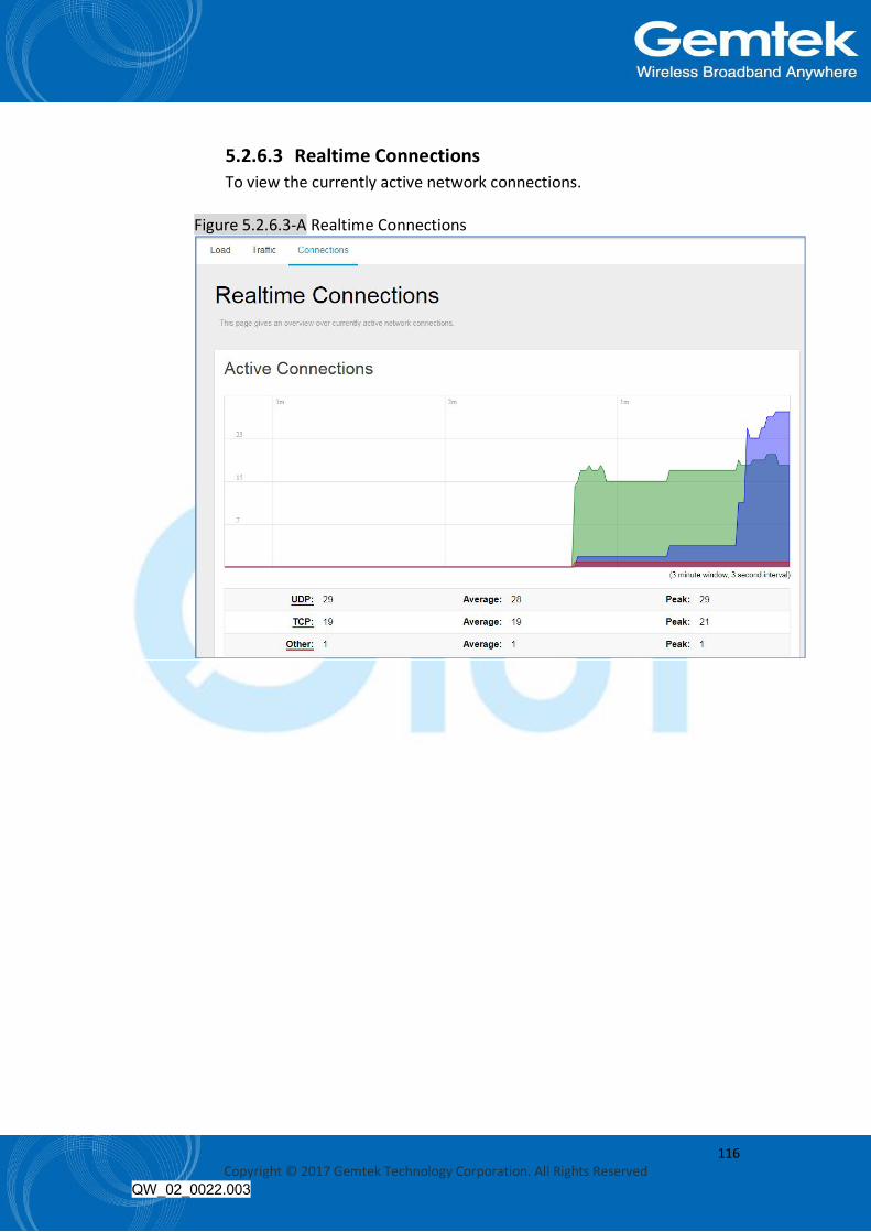
116 Copyright © 2017 Gemtek Technology Corporation. All Rights Reserved
QW_02_0022.003
5.2.6.3 Realtime Connections To view the currently active network connections.
Figure 5.2.6.3-A Realtime Connections

117 Copyright © 2017 Gemtek Technology Corporation. All Rights Reserved
QW_02_0022.003
5.3 GIoT The GIoT menu consists of the following categories: Status, Provision, Configuration, Network Server, Network Server Log, Channel Scan, Channel Setting and GPS MAP.
5.3.1 Status The purpose of this category is to view GIoT information as in its provision code, gateway type, gateway ID or LoRa modules, channels, spreading factor, and GPS status. Figure 5.3.1-A GIoT Info
5.3.2 Provision GIoT provision code can be setup on this page. Figure 5.3.2-A Provision Code

118 Copyright © 2017 Gemtek Technology Corporation. All Rights Reserved
QW_02_0022.003
5.3.3 Configuration Click “PERFORM RESTART” button to restart LoRa server. The latitude and longitude coordinates can be manually embedded in this page. Click “SAVE LOCATION” button after inserting the coordinates or click “SELECT ON MAP” button to be redirected to the map in GPS Settings. User can select Normal-AP, Repeater-AP and Repeater on LoRa Configurations. Figure 5.3.3-A GIoT Management

119 Copyright © 2017 Gemtek Technology Corporation. All Rights Reserved
QW_02_0022.003
5.3.4 Network Server The user can configure Network Server settings on this page. The Femto Cell can connect to the broker via MQTTS or MQTT. Definitions for Cloud Protocol Settings are listed as follows: Protocol: Displays the protocol that is used to connect to the lora data center. Hostname: The IP/domain name address of where the cloud server is located. Username: The username for the cloud server. Password: The password for the cloud server. Publish topic: The publishing topic of the broker set for downlink. (read only) Subscribe topic: The subscription topic of the broker set for uplink. (read only) Downlink ACK: The subscription topic of the broker set for downlink ack. (read only) Port: Displays the port number that is being used. (read only)
Figure 5.3.4-A Network Server

120 Copyright © 2017 Gemtek Technology Corporation. All Rights Reserved
QW_02_0022.003
5.3.5 Network Server Log Displays the log that is connected to the broker. Figure 5.3.5-A Network Server Log
5.3.6 Channel Scan To scan LoRa channel based on ISM regulation and export the result after the scan is completed. Figure 5.3.6-A Channel Scan

121 Copyright © 2017 Gemtek Technology Corporation. All Rights Reserved
QW_02_0022.003
5.3.7 Channel Setting To setup the center frequency for LoRa on this page. Figure 5.3.7-A Channel Setting
5.3.8 GPS MAP To setup the GPS location, simply input your address location in the “Location” text field above the map or pinpoint your location on the map by dragging the red marker to the correct spot. Once the location is confirmed, the system will verify and apply the new Latitude/Longitude coordinates into its GPS setting. Figure 5.3.8-A GPS Setting
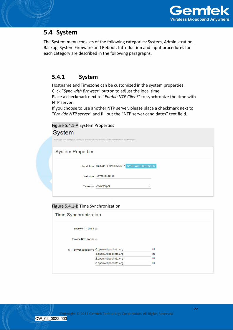
122 Copyright © 2017 Gemtek Technology Corporation. All Rights Reserved
QW_02_0022.003
5.4 System The System menu consists of the following categories: System, Administration, Backup, System Firmware and Reboot. Introduction and input procedures for each category are described in the following paragraphs.
5.4.1 System Hostname and Timezone can be customized in the system properties. Click “Sync with Browser” button to adjust the local time. Place a checkmark next to “Enable NTP Client” to synchronize the time with NTP server. If you choose to use another NTP server, please place a checkmark next to “Provide NTP server” and fill out the “NTP server candidates” text field. Figure 5.4.1-A System Properties
Figure 5.4.1-B Time Synchronization
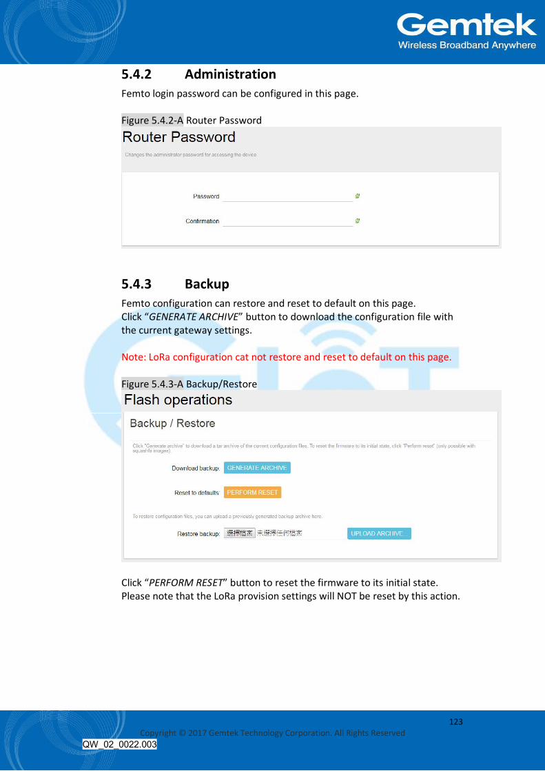
123 Copyright © 2017 Gemtek Technology Corporation. All Rights Reserved
QW_02_0022.003
5.4.2 Administration Femto login password can be configured in this page. Figure 5.4.2-A Router Password
5.4.3 Backup Femto configuration can restore and reset to default on this page. Click “GENERATE ARCHIVE” button to download the configuration file with the current gateway settings. Note: LoRa configuration cat not restore and reset to default on this page. Figure 5.4.3-A Backup/Restore
Click “PERFORM RESET” button to reset the firmware to its initial state. Please note that the LoRa provision settings will NOT be reset by this action.

124 Copyright © 2017 Gemtek Technology Corporation. All Rights Reserved
QW_02_0022.003
Figure 5.4.3-B Backup/Restore
Choose the most recent backup file and click “UPLOAD ARCHIVE” to restore the configuration file.
5.4.4 System Firmware Click “CHECK NEW FIRMWARE” button to search the OTA server for the latest version of the new system firmware. Once a new system firmware version is detected on the OTA server, click “UPGRADE NOW” button to upgrade the newest system firmware from OTA server. Figure 5.4.4-A System Firmware

125 Copyright © 2017 Gemtek Technology Corporation. All Rights Reserved
QW_02_0022.003
5.4.5 Reboot Click “PERFORM REBOOT” to reboot Femto. Figure 5.4.5-A Reboot
5.5 Network The System menu consists of the following categories: WAN, LAN, DHCP, Static Routes and Diagnostics. Introduction and input procedures for each category are described in the following paragraphs.
5.5.1 WAN The purpose of this category is to view current WAN settings. This category is further divided into three sectors: Ethernet Wan and 3G/4G LTE. These individual options are lodged and labeled above the main content panel. Figure 5.5.1-A WAN
5.5.1.1 Ethernet WAN This page is to setup the connection type in terms of Static IP, DHCP client or PPPoE. The three different options can be selected in the drop-down menu in “wantype”. Please fill in the respective fields exhibited under each selection. Please make sure the Ethernet cable is connected to a WAN port.
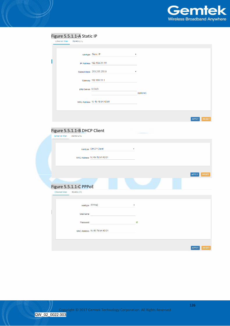
126 Copyright © 2017 Gemtek Technology Corporation. All Rights Reserved
QW_02_0022.003
Figure 5.5.1.1-A Static IP
Figure 5.5.1.1-B DHCP Client
Figure 5.5.1.1-C PPPoE
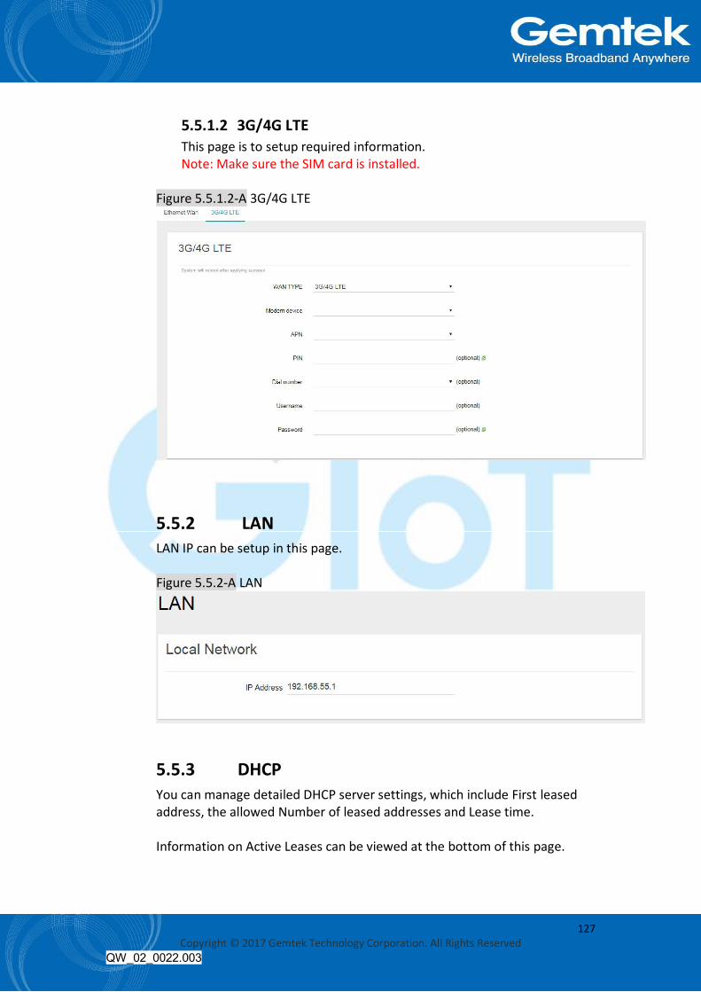
127 Copyright © 2017 Gemtek Technology Corporation. All Rights Reserved
QW_02_0022.003
5.5.1.2 3G/4G LTE This page is to setup required information. Note: Make sure the SIM card is installed.
Figure 5.5.1.2-A 3G/4G LTE
5.5.2 LAN LAN IP can be setup in this page. Figure 5.5.2-A LAN
5.5.3 DHCP You can manage detailed DHCP server settings, which include First leased address, the allowed Number of leased addresses and Lease time. Information on Active Leases can be viewed at the bottom of this page.

128 Copyright © 2017 Gemtek Technology Corporation. All Rights Reserved
QW_02_0022.003
Figure 5.5.3-A DHCP
5.5.4 Static Routes Static routes can be established by clicking the “ADD” button to enter proper settings. Click “Delete” to erase the entry. Always click the “SAVE” button to apply your settings. Figure 5.5.4-A Static Routes

129 Copyright © 2017 Gemtek Technology Corporation. All Rights Reserved
QW_02_0022.003
5.5.5 Diagnostic Diagnostics is divided into three parts on the same page: PING, TRACEROUTE and NSLOOKUP. Please see the following for input guidelines.
5.5.5.1 PING Input a specific IP address in the text field above “PING”. Click the “PING” button to ping the IP you have specified.
Figure 5.5.5.1-A PING
5.5.5.2 TRACEROUTE Input a specific URL or IP address above “TRACEROUTE”. Click the “TRACEROUTE” button to trace the URL or IP address you have specified.

130 Copyright © 2017 Gemtek Technology Corporation. All Rights Reserved
QW_02_0022.003
Figure 5.5.5.2-A TRACEROUTE
5.5.5.3 NSLOOKUP Input a specific URL or IP address above “NSLOOKUP”. Click the “NSLOOKUP” button to view the DNS server of the URL or IP address you have specified.
Figure 5.5.5.3-A NSLOOKUP
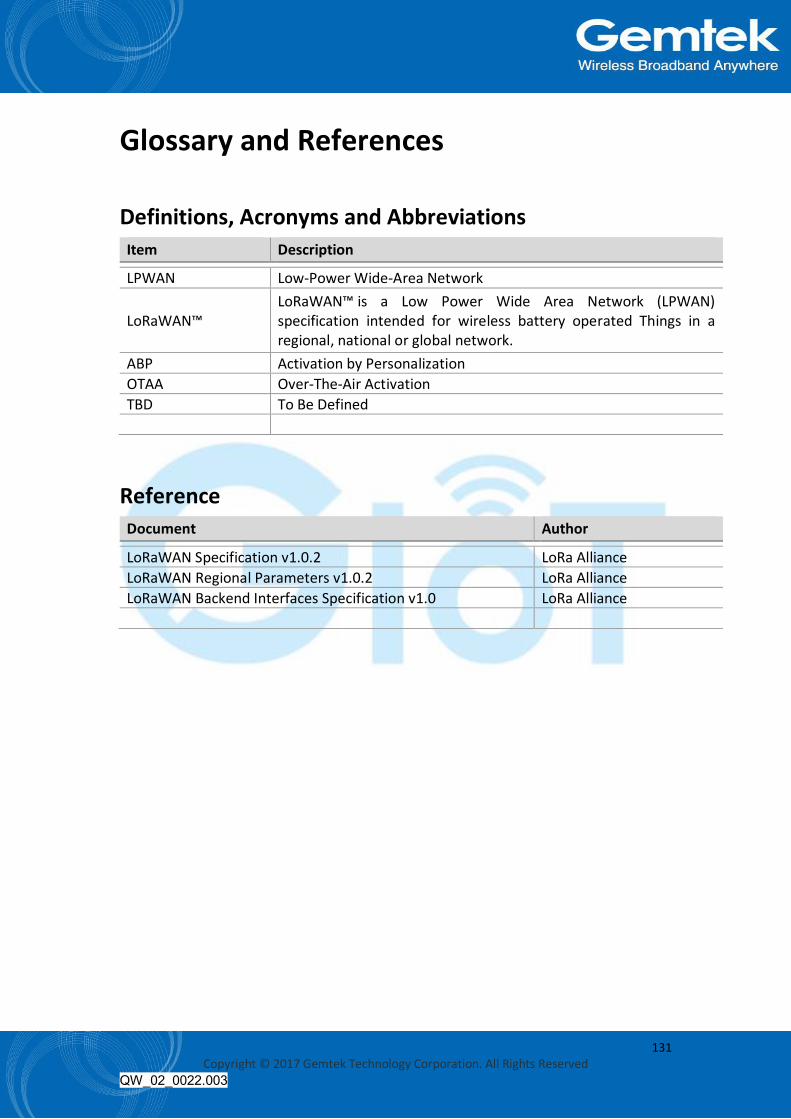
131 Copyright © 2017 Gemtek Technology Corporation. All Rights Reserved
QW_02_0022.003
Glossary and References Definitions, Acronyms and Abbreviations Item Description
LPWAN Low-Power Wide-Area Network
LoRaWAN™ LoRaWAN™ is a Low Power Wide Area Network (LPWAN) specification intended for wireless battery operated Things in a regional, national or global network.
ABP Activation by Personalization OTAA Over-The-Air Activation TBD To Be Defined
Reference Document Author
LoRaWAN Specification v1.0.2 LoRa Alliance LoRaWAN Regional Parameters v1.0.2 LoRa Alliance LoRaWAN Backend Interfaces Specification v1.0 LoRa Alliance