Embed Size (px)
Citation preview

USE
R M
AN
UA
LGUARDIANA5-6000 IP Dispensing System
THIS
EQ
UIP
MENT IS PROTECT
ED
BY
U.S.A. PATENT
D546,840
THIS
EQ
UIP
MENT IS PROTECT
ED
BY
CHINESE PATENT
ZL 200630130159.1
Important Safety InstructionsRead all warnings and instructions in this manual. Save these instructions.
For use with non-flammable foam and polyurea. Not for use in explosive atmospheres.
Maximum fluid working pressure:(1600 psi. (11 MPa, 110 bar)

Table Of Contents
Section 1 Installation
Warnings .................................................................................................................................................................... 2Standard Equipment .................................................................................................................................................. 5Specifications..............................................................................................................................................................6Introduction ................................................................................................................................................................ 7 Equipment Assembly .................................................................................................................................................. 8
Section 2 Operation
Start-up Instructions ................................................................................................................................................... 13Shut–down Instructions .............................................................................................................................................. 17
Section 3 General InformationAssembly Drawings .................................................................................................................................................... 21Sub Assembly Drawings ............................................................................................................................................. 26Maintenance ............................................................................................................................................................... 31Troubleshooting .......................................................................................................................................................... 32
Section 4 Warranty and Reference Information
Notes ............................................................................................................................................. 35
Limited Warranty Policy ................................................................................................................... 37
Technical Assistance ....................................................................................................................... 38For Your Reference ............................................................................................. INSIDE BACK COVER

Warnings
The following warnings are for the setup, use, grounding, maintenance, and repair of this equipment. The exclamation pointsymbolalertsyoutoageneralwarningandthehazardsymbolreferstoprocedure-specificrisk.Referbacktothesewarnings.Additional,product-specificwarningsmaybefoundthroughoutthebodyofthismanualwhereapplicable.
WARNINGELECTRIC SHOCK HAZARDImpropergrounding,setup,orusageofthesystemcancauseelectricshock.
Turn off and disconnect power cord before servicing equipment.•Use only grounded electrical outlets.•Use only 3-wire extension cords.•Ensure ground prongs are intact on sprayer and extension cords.•Do not expose to rain. Store indoors.•
TOXIC FLUID OR FUMES HAZARDToxicfluidsorfumescancauseseriousinjuryordeathifsplashedintheeyesoronskin,inhaled,orswallowed.
ReadMSDS’stoknowthespecifichazardsofthefluidsyouareusing.•Storehazardousfluidinapprovedcontainers,anddisposeofitaccordingtoapplicableguide-•lines.Always wear impervious gloves when spraying or cleaning equipment.•
PERSONAL PROTECTIVE EQUIPMENTYou must wear appropriate protective equipment when operating, servicing, or when in the operating areaoftheequipmenttohelpprotectyoufromseriousinjury,includingeyeinjury,inhalationoftoxicfumes, burns, and hearing loss. This equipment includes but is not limited to:
Protective eyewear•Clothingandrespiratorasrecommendedbythefluidandsolventmanufacturer•Gloves•Hearing protection•
SKIN INJECTION HAZARDHigh-pressurefluidfromgun,hoseleaks,orrupturedcomponentswillpierceskin.Thismaylooklikejustacut,butitisaseriousinjurythatcanresultinamputation.Get immediate surgical treatment.
Do not point gun at anyone or at any part of the body.•Do not put your hand over the spray tip.•Donotstopordeflectleakswithyourhand,body,glove,orrag.•Close material shutoff valves and shutoff or disconnect air supply when not spraying.•Follow • Pressure Relief Procedure in this manual, when you stop spraying and before cleaning, checking,orservicingequipment.
1

WARNINGFIRE AND EXPLOSION HAZARDFlammablefumes,suchassolventandpaintfumes,inworkareacanigniteorexplode.Tohelppre-ventfireandexplosion:
Use equipment only in well ventilated area.•Eliminate all ignition sources; such as pilot lights, cigarettes, portable electric lamps, and plastic •drop cloths (potential static arc).Keepworkareafreeofdebris,includingsolvent,ragsandgasoline.•Donotplugorunplugpowercords,orturnpowerorlightswitchesonoroffwhenflammable•fumes are present.Groundallequipmentintheworkarea.•Use only grounded hoses.•Holdgunfirmlytosideofgroundedpailwhentriggeringintopail.•Ifthereisstaticsparkingoryoufeelashock,• stop operation immediately. Do not use equip-ment until you identify and correct the problem.Keepaworkingfireextinguisherintheworkarea.•
PRESSURIZED ALUMINUM PARTS HAZARDDo not use 1,1,1-trichloroethane, methylene chloride, other halogenated hydrocarbonsolventsorfluidscontainingsuchsolventsinpressurizedaluminumequipment.Suchuse can cause serious chemical reaction and equipment rupture, and result in death,seriousinjury,andpropertydamage.EQUIPMENT MISUSE HAZARDMisusecancausedeathorseriousinjury.
Donotoperatetheunitwhenfatiguedorundertheinfluenceofdrugsoralcohol.•Donotexceedthemaximumworkingpressureortemperatureratingofthelowestratedsystem•component. See Technical Data in all equipment manuals.Usefluidsandsolventsthatarecompatiblewithequipmentwettedparts.See• Technical Data in allequipmentmanuals.Readfluidandsolventmanufacturer’swarnings.Forcompleteinforma-tion about your material, request MSDS forms from distributor or retailer.Checkequipmentdaily.Repairorreplacewornordamagedpartsimmediatelywithgenuine•manufacturer’s replacement parts only. Do not alter or modify equipment.•Use equipment only for its intended purpose. Call your distributor for information.•Routehosesandcablesawayfromtrafficareas,sharpedges,movingparts,andhotsurfaces.•Donotkinkoroverbendhosesorusehosestopullequipment.•Keepchildrenandanimalsawayfromworkarea.•Comply with all applicable safety regulations.•
MOVING PARTS HAZARDMovingpartscanpinchoramputatefingersandotherbodyparts.
Keep clear of moving parts.•Do not operate equipment with protective guards or covers removed.•Pressurizedequipmentcanstartwithoutwarning.Beforechecking,moving,orservicingequip-•ment, follow the Pressure Relief Procedure in this manual. Disconnect power or air supply.
BURN HAZARDEquipmentsurfacesandfluidthat’sheatedcanbecomeveryhotduringoperation.Toavoidsevereburns,donottouchhotfluidorequipment.Waituntilequipment/fluidhascooledcompletely.
Warnings
2

Warnings
Isocyanate Hazard
Spraying materials containing isocyanates creates potentially harmful mists, vapors, and atomized particulates.
Read material manufacturer’s warnings andmaterialMSDStoknowspecifichazardsandprecautions related to isocyanates.
Prevent inhalation of isocyanate mists, vapors, and atomizedparticulatesbyprovidingsufficientventila-tionintheworkarea.Ifsufficientventilationisnotavailable, a supplied-air respirator is required for everyoneintheworkarea.
To prevent contact with isocyanates, appropriate personal protective equipment, including chemically impermeable gloves, boots, aprons, and goggles, is alsorequiredforeveryoneintheworkarea.
Material Self-Ignition
Some materials may become self-igniting if applied toothickly.Readmaterialmanufacturer’swarningsand material MSDS.
Moisture Sensitivity of IsocyanatesIsocyanates (ISO) are catalysts used in two component foam and polyurea coatings. ISO will react with moisture (such as humidity) to form small, hard, abrasive crystals, whichbecomesuspendedinthefluid.Eventuallyafilmwillform on the surface and the ISO will begin to gel, increas-ing in viscosity. If used, this partially cured ISO will reduce performance and the life of all wetted parts.
Theamountoffilmformationandrateofcrystal-lization varies depending on the blend of ISO, the humidity, and the temperature.
To prevent exposing ISO to moisture:
Always use a sealed container with a desiccant dryer •in the vent, or a nitrogen atmosphere. Never store ISO in an open container.
KeeptheISOlubepumpreservoirfilledwithGraco•Throat Seal Liquid (TSL), Part 206995. The lubricant creates a barrier between the ISO and the atmosphere.
Usemoisture-proofhosesspecificallydesignedfor•ISO, such as those supplied with your system.
Never use reclaimed solvents, which may contain •moisture.Alwayskeepsolventcontainersclosedwhennot in use.
Never use solvent on one side if it has been contami-•nated from the other side.
Alwaysparkpumpswhenyoushutdown.•
Always lubricate threaded parts with Part 217374 ISO •pump oil or grease when reassembling.
3

Keep Components A and B Separate
CAUTIONTo prevent cross-contamination of the equipment’s wet-ted parts, never interchange component A (isocyanate) and component B (resin) partrs. The gun is shipped with theAsideontheleft.Thefluidmanifold,fluidhous-ing,sidesealassembly,checkvalvecartridge,andmixchamberaremarkedontheAside.
Foam Resins with 245 fa Blowing AgentsNew foam blowing agents will froth at temperatures above 90°F (33 °C) when not under pressure, especially if agitat-ed. To reduce frothing, minimize preheating in a circulation system.
Changing MaterialsWhenchangingmaterials,flushtheequipmentmul-•tiple times to ensure it is thoroughly clean.
Alwayscleanthefluidinletstrainersafterflushing.•
Checkwithyourmaterialmanufacturerforchemical•compatibility.
Most materials use ISO on the A side, but some use •ISO on the B side.
Epoxies often have amines on the B (hardener) side. •Polyureas often have amines on the B (resin) side.
Warnings
4

Section 1 - Installation: Standard Equipment
Model - A5-6000 IP
* Purchased Separately
Part Number Description
GC1751 A5-6000 IP UNIT, 220V, 1PH, F
GCP2R2* PROBLER P2 GUN
GC0393* 48 FT. HEATED HOSE ASSEMBLY
GC0319 GRAVITY FEED KIT
313273 USER MANUAL206995 FLUID, TSL, 1 QT. BOTTLE
Part Number Description
GC1748 HEATER REPAIR KIT
Part Number Description
313277 MATERIAL PUMPS MANUAL
5
Recommended Repair Parts
Related Manuals

6
Material Ratio: 1:1 (Fixed)
Material Viscosity: 200- 2000 Centipoise (Cps) @ AMBIENT Output: Pumps Rated: .042 Gallons Per Cycle .159 Liters Per Cycle
Operating Temperatures: 32º F ( 0º C ) - 180º (82 º C )
MaximumAirWorkingPressure: 100psi(0.69MPa,6.9bar)MaximumFluidWorkingPressure: 16:1RATIO1600psi(11MPa,110bar)
ElectricalRequirements: 50A@208/240VAC,50/60hz,SinglePhase (cable: 6 AWG, 2 wire and ground)
Compressed Air Requirements: Base Unit: 1.0 GAL PER MINUTE – 17 CFM @ 100 PSI. 1.5 GAL PER MINUTE – 24 CFM @ 100 PSI. 2.0 GAL PER MINUTE – 33 CFM @ 100 PSI. NOTE:Asoutputisincreased,(achievedw/chamber size on gun or spray tip), pressure drop will be greater. Heating capability will also drop.
Heaters: 6000 WATT HEATER
Maximum Hose Length: 200 ft (61 m) (EachSection50ftx1/4in.I.D.)
ShippingWeight: 428lbs.(194kg)
Overall Dimensions:
Section 1 - Installation: Specifications

Before operating, maintaining or servicing any GlasCraft system, read and understand all of the technical and safety literature provided with GlasCraft products. If you do not have the proper or related manuals and safety literature for your GlasCraft system, contact your GlasCraft distributor.
In this GlasCraft technical and safety publication, the following advisories will be provided where appropriate:
Is information about the procedure in progress.
Is imperative information about equipment protection.
Indicates a hazardous situation that can result in minor or moderate injury.
Indicates a hazardous situation that can result in death or serious injury.
Indicates a hazardous situation that can result in electrical shock or serious injury.
The information in this document is intended only to indicatethecomponentsandtheirnormalworkingrelationship typical use. Each assembly should be directed by a GlasCraft distributor or made from theGlasCraft Assembly instructions provided.
This manual provides information for the assembly, opera-tion, maintenance and service of this GlasCraft product asusedinatypicalconfiguration.Whileitlistsstandardspecifi-cations and procedures, some deviations may be found.
In order to provide our users with the most up-to-date technologypossible,weareconstantlyseekingtoimproveproducts. If technological change occurs after a product is onthemarket,wewillimplementthattechnologyinfutureproductionand,ifpractical,makeitavailabletocurrentusersasaretrofit,up-dateorsupplement.Ifyoufindsomediscrepancy between your unit and the available documen-tation, contact your GlasCraft distributor to resolve the difference.
Careful study and continued use of this manual will pro-vide a better understanding of the equipment and process, resultinginmoreefficientoperation,longertrouble-freeservice and faster, easier troubleshooting.
ELECTRICAL SHOCK HAZARD
WARNING
CAUTION
Section 1 - Installation: Introduction
7

Section 1 - Installation: Equipment Assembly
Guardian Line Installation Guide
GlasCraft Systems are factory assembled. If any questions arise concerning air or electrical connections, please refer to illustrations located in the forward portion of this User Manual or contact your GlasCraft distributor.
1. Locate Guardian.
a. Locate Guardian on a level surface.
b. Do not expose Guardian to rain.
CAUTION Bolt Guardian to original shipping palet before lifting.
c. UsethewheelstomoveGuardiantoafixed location, or bolt to shipping pallet and movewithforklift.
d. Tomountonatruckbedortrailer,boltdirectlytotruckortrailerbed.
2. Advanced preparation
a. Before beginning any installation, ensure that the applicator has the desired power supply available,(i.e.220Vsinglephase/380Vthreephase), within 10 ft. of were the machine is to be placed. If the machine needs to be further that 10 ft. from the power supply, additional lengths of properly sized electrical cable will be required.
Never use a smaller gauge size than supplied by the factory!
b. Depending on the electrical setup, it may be necessary to install an appropriate plug on the end of the cable. GlasCraft will not supply this plug, as we are unaware of which style will be needed. c.Consultthedatasheetforthespecificunitbeinginstalledtodeterminetheproperbreakersize needed.
d. You will need to run an air line to the area where the machine will be placed. consult the datasheetthespecificunitbeinginstalledtodetermine much clean, dry air will be needed to supply the machine. If the air line is under 25 ft. use a minimumof1/2in.I.D.pipeorhose.Iftheairline is longerthan25ft.,useaminimumof3/4in. pipe or hose. Anything smaller than these diameters will severly affect the machine’s performance!
Do not use any quick disconnect fittings on the main air line going to the machine!
Check your air-compressor to make sure it is capable of supplying the maximum amount of air that the machine requires. All GlasCraft equipment is rated at 25 CFM (cubic foot per minute) 708 liters at 90- 100 psi (.62-0.7 MPa, 6.3-7.7 bar) do not exceed 125 psi (0.86 MPa, 8.6 bar).
3. Move material drums to the area that the equipment will be placed, ensuring that they are not sitting directly on thefloor.Simplyplacethedrumsontopofapalateor similar device, so the drum bottoms will not be in contact with any cold surfaces.
4. Open all boxes that came with the machine and verify that all items are accounted for.
8

9
Section 1 - Installation: Equipment Assembly
4. Install the gravityfeedkitGC0319asshown.
GC2161
GC1979GC0085
GC2208GC0005
GC2214
3/4in.IDHOSE

10
Section 1 - Installation: Equipment Assembly
Main power from power source should be discon-nectedor turnedoff to consolebeforemakinghoseconnections.
Trigger Air
5. Connect the hose assembly to the unit. TheswivelfittingsontheHoseassembly are sized differently and will attach only one way.
6. Connect the “yellow” heat plug to the outlet on the front of the unit.
7. Connect trigger air line to the air regulator at the system air manifold.
8. Connect the thermocouple plug to the outletonthe“back”oftheunit.

11
Section 1 - Installation: Equipment Assembly
9. Continue adding extra hose lengths if necessary.
The GlasCraft System is factory assembled. If any questions arise concerning air or electrical connections, please refer to illustrations located in the forward portion of this User Manual or contact your GlasCraft distributor.
Required Tools: Opened-endwrenches-5/8in.,3/4in.,13/16in.
a. Lay hoses out straight.
b. Couplehosestogetherwithsuppliedunionfittingsandtightenfinger-tight.
c. •Holdcrimpfittinghex(3/4in.),andunionfitting together, allowing the hose to hold it’s natural line.
•Usingtheappropriatewrench(A-side3/4in./B-side13/16in.)tightenswivelfittingtounion,notallowingcrimpfittingoruniontoturn.Repeaton opposite side of union.
This practice is required on all connection points. 1) Hose @ machine 2) Hose @ gun 3) Adding additional hose sections
d. Attach the yellow power plugs.
e. Attach the thermocoupleextensioncable.p/nGC0885.
GC0705 Extension hose Machine End
Machine End
GC0393 Standard hose Gun End

12
Section 1 - Installation: Equipment Assembly
10. Connect the hose assembly to the spray gun as shown.
11. All connections should now be tight!
When Main Power to system console is on, the white and black wires in the console are always live! Disconnect or turn off Main Power source before opening console to make any repairs or before making any electrical repair of any type to the system.
If you do not understand the electrical hook-up described above, consult your local GlasCraft distributor OR a qualified electrician.
Electrical connections must be checked on a periodic basis.
12. ConnectthewhiteandblackwiresofthePowercordtoasinglephaseof208/240VAC,50/60HZ. The green wire should be connected to GROUND
WHITE
GREEN
BLACKPOWER CORD
208 / 240 VAC50 / 60 HZ.
SINGLE PHASE25 AMP MIN.
GROUND
50

13
Never leave machine unattended while system power is on or system is running. System running is defined as: preheat cycle of the hose heat, primary heaters, or any pump operation. Machine operators must be familiar with the component functions and operation of the machine.
Pre-Operation Check List
A. Checkthatallfittingsaresecurelytight.
B. Checkelectricalhook-up(qualifiedelectrician recommended).
C. Main power switch on control box should be switched to OFF position.
D.Airregulatorturned(counterclock-wise)toOFF position.
E. Hose control and primary heater control to OFF position.
Do not place any part of the body in the path of the material spray. Do not point the gun at or near other personnel. Do not look into the mixing chamber orifice at any time. Because of the hazardous materials used in this equipment, it is recommended that the operator use an air mask, goggles, protective clothing, and other safety equipment as prescribed by current regulations, recommendations of the chemical suppliers, and the laws in the area where the equipment is being used.
Initial Start-Up Procedure With all material and air lines connected and power cable attached, the system is now ready for start-up.
Filling The System
1. Adjustairregulatorto20psitofillsystem.Airmotorwillcycleslowlytofillpumps,heatersand hoses and stop.
2. RemoveISO&POLYsideblocksfromgun.
PROBLER P2MAKE SURE VALVES ARE OFF
Section 2 - Operation: Start-Up Instructions

14
3. Place separate clean containers under each indi-vidualsideblock.Slowly open material valves (blackarrowforward)oneachsideblocktoallowtrappedairtoescapethehoseandmaterialtoflow into the containers until all air is purged from the material system.
Remember to dispense one to two gallons of material to clear the system of grease and plasticizer that was used during factory testing.
4. Close manual material valves. Material pressure gauges should now register approximately equal pressure. If one side registers considerably more pressure than the other side, go to the high pres- sure side and bleed off some pressure by slightly opening the manual material valve on the side blockoverthecontainer.Bleedpressureuntilboth sides are approximately the same pressure.
5. Dispose of waste material properly and in accor- dance with chemical suppliers instructions and local, state and federal regulations.
Before re-assembling Side Blocks, lubrication can be applied by dabbing a white lithium grease into holes inside of Gun Front Housing and wiping grease over SideBlock Seals. Grease will purge itself when air valve is turned on at Gun and Gun is triggered.
6.CleanandlubricateSideBlocksandSealsthoroughlyandre-assembleonGun.Makecertainthatthesideblockscrewsaretightenedsecurely.
7. Refer to material manufacturers operating instructions for proper preparation of material, i.e, mixers, etc.
8. Leave Air Regulator at 20 PSI
9. Turn main power Switch to ON position.
10. Turn on Hose Control: a. Push in the green power button. b. Press up or down arrow buttons on the controller until desired temperature setting is achieved.
Section 2 - Operation: Start-Up Instructions
15
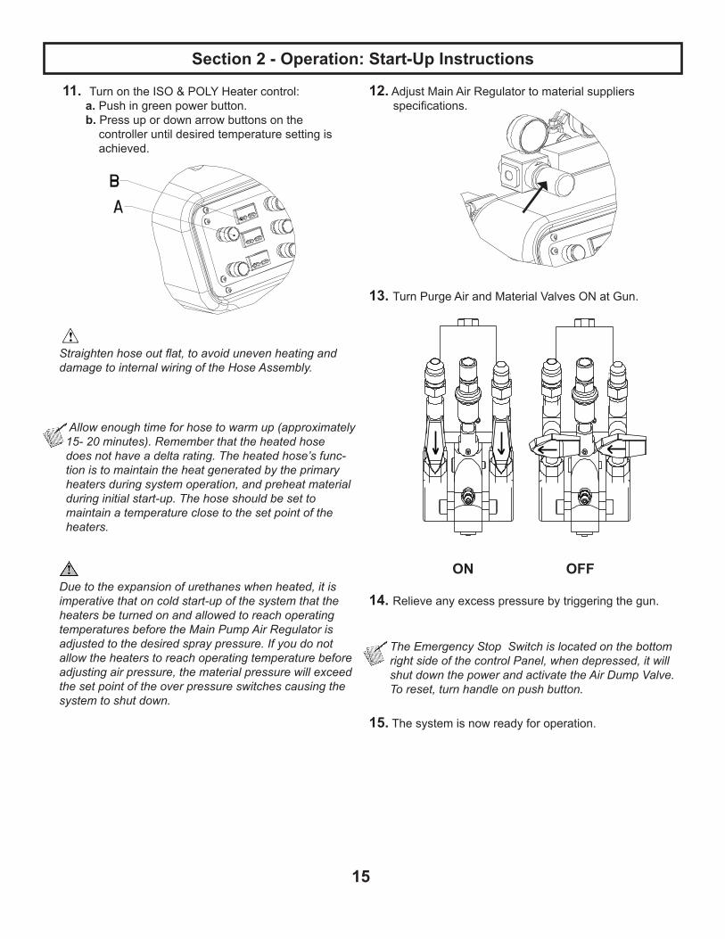
11. Turn on the ISO & POLY Heater control: a. Push in green power button. b. Press up or down arrow buttons on the controller until desired temperature setting is achieved.
Straighten hose out flat, to avoid uneven heating and damage to internal wiring of the Hose Assembly.
Allow enough time for hose to warm up (approximately 15- 20 minutes). Remember that the heated hose does not have a delta rating. The heated hose’s func- tion is to maintain the heat generated by the primary heaters during system operation, and preheat material during initial start-up. The hose should be set to maintain a temperature close to the set point of the heaters.
Due to the expansion of urethanes when heated, it is imperative that on cold start-up of the system that the heaters be turned on and allowed to reach operating temperatures before the Main Pump Air Regulator is adjusted to the desired spray pressure. If you do not allow the heaters to reach operating temperature before adjusting air pressure, the material pressure will exceed the set point of the over pressure switches causing the system to shut down.
12.AdjustMainAirRegulatortomaterialsuppliersspecifications.
13. Turn Purge Air and Material Valves ON at Gun.
ON OFF
14. Relieve any excess pressure by triggering the gun.
The Emergency Stop Switch is located on the bottom right side of the control Panel, when depressed, it will shut down the power and activate the Air Dump Valve. To reset, turn handle on push button.
15. The system is now ready for operation.
Section 2 - Operation: Start-Up Instructions

16
Change Temperature Controller Display Units (Fhrenheit or Celsius)
220 V units are factory set to display temperature readings in degrees Fahrenheit. 380 V units are factory set to display tempertature readings in degrees Celsius.
The temperature display units can be changed with the fol-lowing procedure: 1. On the Watlow SD31 controller, press and hold the and buttons simultaneously for 3 seconds until the display reads “SET”. This is the Setup Menu.
2. Scroll through the Setup Menu by pressing the . button until the display reads “C-F” (press button 3 times).
3. Press and hold the button to display the current unit setting of “C” of “F”.
4. Continue to hold the button and press the button to switch to the desired unit setting, “C” or “F”.
5. Release the button.
6. Presstheinfinitybutton to exit the Setup Menu; the temperature display unit is now changed.
7. Complete steps 1-6 for all three controllers (ISO, POLY, HOSE).
Do not change any other settings in the Setup Menu. The settings have been factory programmed for opti- mal performance.
Section 2 - Operation: Start-Up Instructions
17
Daily Shut-Down Procedure
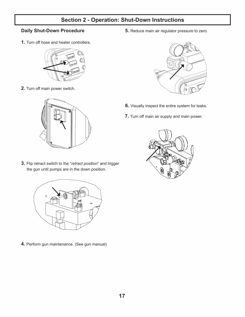
1. Turn off hose and heater controllers.
2. Turn off main power switch.
3. Flip retract switch to the “retract position” and trigger the gun until pumps are in the down position.
4. Perform gun maintenance. (See gun manual)
5. Reduce main air regulator pressure to zero.
6. Visuallyinspecttheentiresystemforleaks.
7. Turn off main air supply and main power.
Section 2 - Operation: Shut-Down Instructions

18
8. Coil heated hoses with a minimum four foot diametertoavoidkinkingandsubsequentdamagetothe internal electrical wiring.
9. Checkandlubetopofthefluidsection.
Wipe off residual material and add a tablespoon of throat seal liquid (TSL).
Do not bleed fluid pressure from the system.
Extended Shut-Down Procedure
The following procedure is for long extended shut-down periods.
Power should be disconnected and all air regulators turned down to zero.
1.Removesideblocksfromthegunandrelievepressure from the system.
2. Useasuitablesolventtoflushthefluidcircuits.To determine the compatibility of solvents with materialbeingused.Alwayscheckwithmaterialsupplier.
3. Increasetransferpumppressureuntilfluid movement occurs.
IffluidmovementdoesNOT occur @ 100 psi of air on transfer pumps, increase main pump pressure until the main proportioner SLOWLY starts cycling.
4. Onceprimarymaterialisflushedfromthesystem,reducethemainairpressuretozeroorflipthe retract switch to the “retract position” and trigger the gun until the pumps are in the down position.
5. Ifthesolventusedtoflushthesystemalsocontainsplacticizer,ensurethatallprimarymaterialisflushed from the system and close the ball valves @ the gun.
6. Leavethepumpsinthefulldownstrokepositionwithapproximately200-500psi.onthefluidgauges.
7. If plasticizer is required to chase out solvent, cycle main pumps until the system is full of plasticizer, then close valves and leave the pumps in the full downstrokepositionwith200-500psi.
PROBLER P2
Section 2 - Operation: Shut-Down Instructions
19
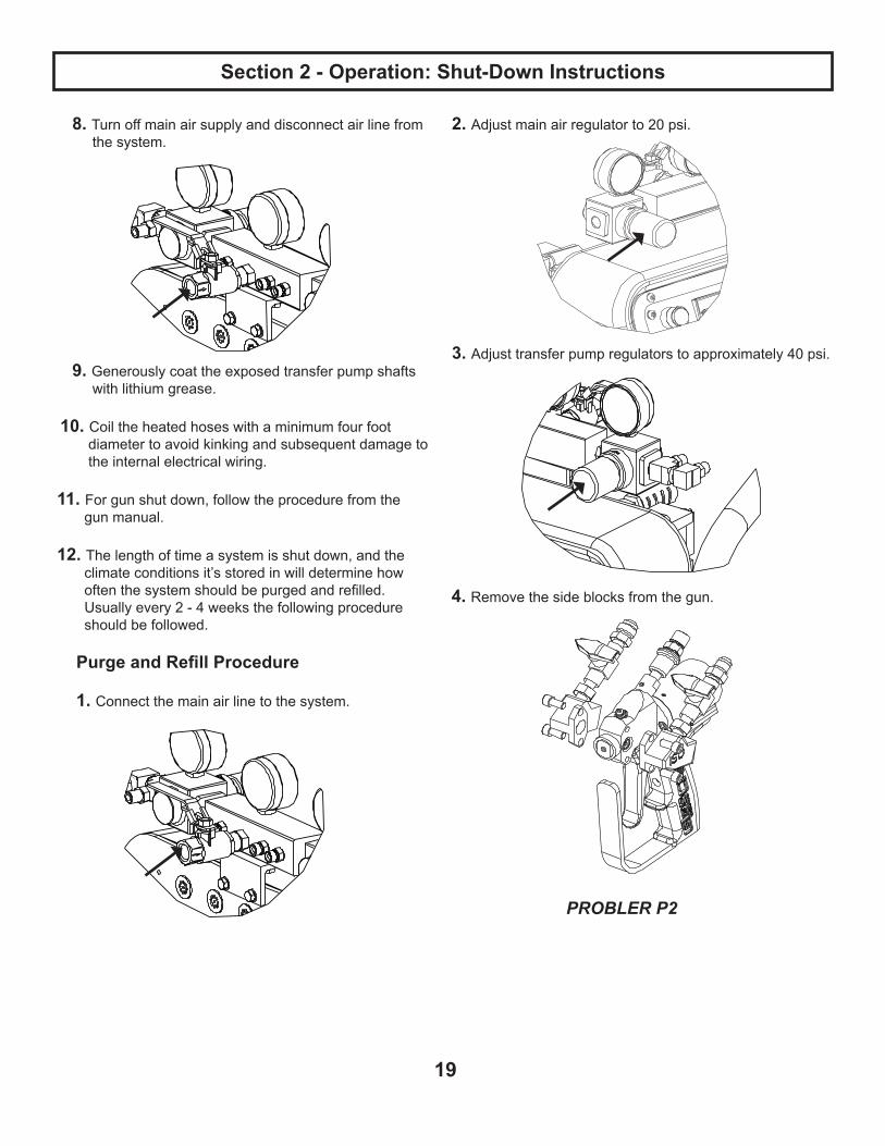
8. Turn off main air supply and disconnect air line from the system.
9. Generously coat the exposed transfer pump shafts with lithium grease.
10. Coil the heated hoses with a minimum four foot diametertoavoidkinkingandsubsequentdamageto the internal electrical wiring.
11. For gun shut down, follow the procedure from the gun manual.
12. The length of time a system is shut down, and the climate conditions it’s stored in will determine howoftenthesystemshouldbepurgedandrefilled.Usuallyevery2-4weeksthefollowingprocedure should be followed.
Purge and Refill Procedure
1. Connect the main air line to the system.
2. Adjustmainairregulatorto20psi.
3. Adjusttransferpumpregulatorstoapproximately40psi.
4. Removethesideblocksfromthegun.
Section 2 - Operation: Shut-Down Instructions
PROBLER P2

20
5. Openbothsideblockssimultaneouslyintoseparatecontainersanddispenseapproximately1-1/2-2 gallons of material from each side or until all plasticizer is purged from the system. Stop the pumps in the down position.
6. Closebothsideblockssimultaneouslyandwipeoffresiduefromthesideblockseals.Regreaseandattachbothblockstothegun.
7. Mix and properly dispose of purge material.
Before performing any repairs on the system, ALL AIR and FLUID PRESSURES SHOULD BE RELIEVED TO ZERO (BLEED-OFF)!
To relieve Air and Fluid pressures:
System Console: 1. Turn OFF valves that supply material to the Pumps. 2. Turn OFF Main Air Regulator on Air Motor.
Gun:1.OpenbothSideBlockMaterialValves. 2. Turn ON Air Switch. 3. Point Gun into a clean, suitable container and triggerGununtilmaterialflowstops. 4. Fluid pressure gauges must read zero (0), if not, triggerGununtilthefluidpressuregaugesdoread zero (0) pressure.5.TurnOFFSideBlockMaterialValves. 6. Trigger Gun several more times to purge any material remaining in Gun. Turn OFF air Switch. 7. Unless system is to be returned to service at once, follow DAILY SHUT-DOWN PROCEDURE
Before performing any repairs on any part of the system, PLACE ALL CONTROLS ON THE MACHINE AND THE MAIN POWER SOURCE IN THE OFF POSITION AND DISCONNECT THE ELECTRICAL POWER CABLE FROM THE MAIN POWER SOURCE!
Section 2 - Operation: Shut-Down Instructions

21
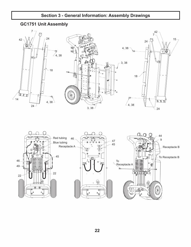
Section 3 - General Information: Assembly Drawings
GC1751 Unit Assembly
20
5, 38
48
48
25
8 2
47
23
11
17
21
supplied with cart assembly
35, 37, 41
39, 40
19
10, 36
1313
165, 38
5, 38 26
27
See Detail A
Some parts have been removed for clairty.
Detail A
1, 36
included with control panel
22
Section 3 - General Information: Assembly Drawings
GC1751 Unit Assembly
4, 38
4, 38
3, 38
3, 38
4, 38
4, 38
44
4745
46
45
22
46
49
22
Red tubingBlue tubing
9
Receptacle BReceptacle A
To Receptacle BTo Receptacle A
24
24
14
18
77 42
42 15
24
24
18

23
Section 3 - General Information: Assembly Drawings
GC1751 Parts List
Ref. Part Description Qty.
1* RIVET, BLIND, 0.188 dia.x 0.425 STL 52 15G280 LABEL, WARNING 13 112925 SCREW, CAP, BTNHD 104 GC0433 SCREW, BHDC, SS, 0.250-20X 0.625 45 GC0434 SCREW, BHDC, SS, 0.250-20X 0.875 127 GC0578 ELBOW,JIC,3/8NPTMX3/4UNFS 2.8 GC0797 LABEL, LIVE WIRE 19 GC0811 CONNECTOR 110* SCREW, 1 IN, #10, SELF TAP 411 GC1071 SWITCH,POWER,ON/OFF 112* CABLE, POWER, 11 FT 113 GC1181 GAUGE, PRESSURE, 3000PSI,
BACK MT2
14 GC1714 HEATER, ASSY, HEATER, DUAL, ROD, ISO
1
15 GC1716 HEATER, HEATER, DUAL, ROD, POLY, 1500
1
16 GC1718 PLATE, BOTTOM 117 CART, ASSY., 1 P; SEE PAGE 26 118 GC1725 COVER, HEATER 219 GC1726 COVER, SHELL 120 GC1730 RING, PANEL, CONTROL 121 GC1736 PUMP, ASSY. 122 GC1744 HOSE, ASSY 223* NUT, RIVET 424 GC1746 WASHER, FIBER 425 GC1756 LABEL, DECAL, GUARDIAN, A5-
6000 IP1
26 CONTROL, PANEL; SEE PAGE 28 127 GC1767 CONTROL,A5/A6-6000IP,220V,1PH 135 GC2052 WASHER, FLAT 236* WASHER, FLAT 937 GC2107 WASHER, LOCK, SPRING 238 GC2109 WASHER, LOCK, SPRING 2639 GC2112 WASHER, LOCK, SPRING 240 GC2175 SCREW 241 GC2192 SCREW 242 GC2203 FITTING, CONNECTOR 244* HOSE, TUBNG, P.E., 0.500OD
NATURAL; 1.4 FT.1
45 GC2363 LABEL, ISO 246 GC2364 LABEL, POLY 247 GC2365 LABEL, HOSE 248 GC2368 LABEL, MAIN 249 GC0805 SWITCH, PRESSURE, HIGH 2
* Source locally.
Not Shown.
Replacement danger and warning labels, tags, and cards are available at no cost.

24
Section 3 - General Information: Assembly Drawings
GC1751 Generic System Schematic
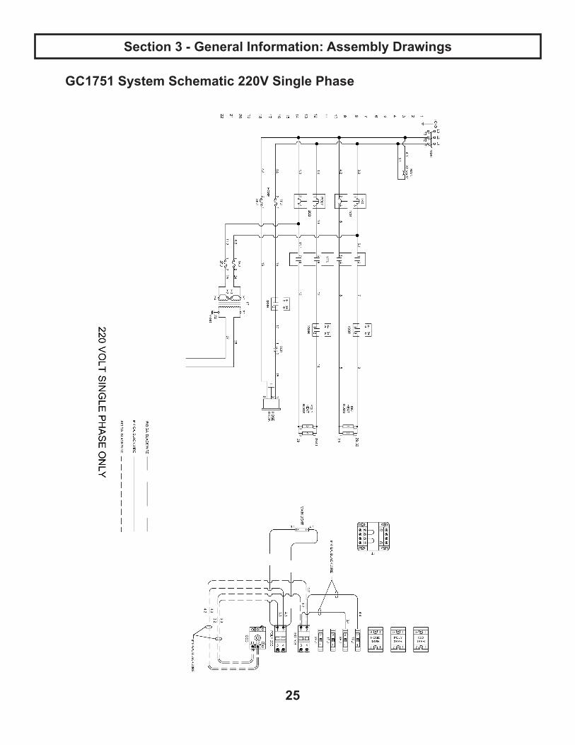
GC1751 System Schematic 220V Single Phase
25
Section 3 - General Information: Assembly Drawings

Section 3 - General Information: Sub Assembly Drawings
26
Cart Assembly IP
106
134, 142 145
137
135123
128
144
125121
117
118118
108
101
102
106
105
124
141
141
130,148
130,148
130,148
130,148
120
142
109
149150
129
132
133
113113
113
104
108
107
103
104
Attach air line for gun here
132
146
112 136,140,143
134,142,144
111
147
138140
See Detail
Detail A
Some Parts Removed For Clarity
Some Parts Removed For Clarity
106141
154, 155, 156
153151, 152, 140, 136
158157

27
Section 3 - General Information: Sub Assembly Drawings
Ref. Part Description Qty.
101 GC0012 ELBOW 2102 GC0025 PLUG, PIPE 1103 GC0217 FITTING,ADAPTER,NPSM,1/4
X1/41
104 GC0286 HOSE, ASSY 1105 GC0409 SCREW, BHDC, SS, .312-18X
.7502
106 112925 SCREW, CAP, BTNHD 10107 GC0437 SCREW,SET,SOC.,7/16-20X
3/81
108* RETAINER, PLUG, VENT, RETAINER
7
109 GC0790 HOSE, ASSY 2111 GC0999 TRANSFORMER, BOX,
CONTROL1
112 GC1040 CONNECTOR 1113 15W209 JACK, PANEL, CIRCULAR 3117 GC1719 HANGER, PANEL, CONTROL 2118 GC1723 COVER, HEATER 2120 GC1738 FITTING,BULKHEAD,1/4NPTX
1/4NPT2
121 GC1739 NUT,BULKHEAD,3/4-16 2123 GC1743 WHEEL 2124 GC1749 MANIFOLD, ASSY, AIR 1125 GC1754 MANIFOLD, ASSY, FLUID 1128 GC1810 COUNTER, WEIGHT 4129 GC1811 EXTENSION, STANDOFF 4130 GC1999 NUT,CONDUIT,ELEC.,1/2 4132* GROMMET,RUBBER,3/8THRU,
1/4PT2
133* GROMMET,RUBBER,1-1/2THRU,1/4PT
1
134 GC2044 WASHER, FLAT 8135 GC2045 WASHER, FLAT, FENDER 2136 GC2048 WASHER, FLAT, STD 1137* WASHER, FLAT, STD 4138 GC2052 WASHER, FLAT, STD 4140 GC2107 WASHER, LOCK, SPRING 5141 GC2109 WASHER, LOCK, SPRING 10142 GC2110 WASHER, LOCK, SPRING 10
Part Description Qty.
GC0020 FITTING 3GC0222 REGULATOR, AIR 2GC0240 GAUGE, AIR, 2GC0241 GAUGE, AIR 1
* FITTING, ELBOW 1GC0755 VALVE, BALL 1GC1720 BRACKET, L 1GC1732 MANIFOLD, AIR 1GC0000 CAP, OILER 2GC0001 GASKET, CAP, OILER 4GC1994 FITTING, ELBOW 1
GC2016 FITTING, PIPE, TEE 1GC2110 WASHER,LOCK, SPRING 2GC2167 FITTING, PIPE, NIPPLE, HEX 2GC2169 FITTING, PIPE, NIPPLE, HEX 2GC2170 FITTING, PIPE, NIPPLE, HEX 1GC2179 SCREW 2GC1772 LABEL, GLASCRAFT, MANIFOLD,
GRDN1
Cart Assembly IP
Ref. Part Description Qty.
143 GC2119 SCREW 1144 GC2180 SCREW 6145 GC2185 SCREW 4146* SCREW 4147 GC2192 SCREW 4148 GC2372 GRIP, CORD 4149* NUT, CONDUIT 1150* CONNECTOR 1151 GC0796 SOLVENT, RECEPTACLE 1152 GC2092 NUT, HEX, STD, 8-32 2153 GC1740 BRACKET, RECEPTACLE,
HOSE1
154 GC1612 PLATE, COUPLING 1155 GC1621 LIGHT, PILOT, WHITE 1156 GC1625 LIGHT, LED, WHITE, 240V 1157 GC2207 FITTING,#6JICx1/4NPT 1158 GC0242 FITTING,5/8-18SAEX1/4NPT 1
* Source locally.

28
Section 3 - General Information: Sub Assembly Drawings
Control Panel Assembly
Ref. Part Description Qty.
201 GC0584 COUNTER, LCD 1
202 GC0599 FUSE,1/2AMP 3203 GC0601 FUSE, 2AMP 1204 15W684 MODULE, HEATER CONTROL,
GUARDIAN2
205* RAIL, DIN; 0.875
208 GC0859 FUSE, FUSEHOLDER, DIN RAIL 4209 GC0956 LABEL, EMERGENCY STOP 1210 GC0972 BLOCK, JUMPER, TERMINAL 2212 GC1161 RELAY, 3 POLE 10AMP 4
213 GC1164 SOCKET, RELAY, 3 POLE, 10AMP 4214 GC1172 TERMINAL,2IN/2OUT 6215 GC1173 COVER, END, TERMINAL, 2 in.,2 OUT 3
217 GC1608 BUTTON, LATCHED 2218 GC1609 BUTTON, MOMENTARY 3219 GC1611 BUTTON, EMERGENCY STOP 1220 GC1612 PLATE, COUPLING 6
Ref. Part Description Qty.
221 GC1614 LENS, ILLUMINATED, "R" 3
222 GC1616 LENS,ILLUMINATED,"I/O" 2223 GC1617 LENS, YELLOW 3224 GC1619 LENS, GREEN 2225 GC1622 LED, YELLOW, 24V 3226 GC1624 LED, GREEN, 24V 2227 GC1626 BLOCK, CONTACT, NORMALLY
OPEN5
228 GC1627 BLOCK, CONTACT, NORMALLY CLOSE
5
230 GC1779 CABLE, PLUG, ELEC., FEMALE 2231 GC1780 CABLE, PLUG, ELEC.,FEMALE 1
232 GC1782 CABLE,PLUG, ELECTRICAL, MALE, 6, SM
2
233 GC1783 CABLE, PLUG, ELECTRICAL, MALE
1
236 15W687 MODULE, HOSE CONTROL, GUARDIAN
1
* Source locally.
204
228
201
228209
227
223218221225
222224220217226
220
202
219220227
203
210
208
205
212
236
213
215214

29
Section 3 - General Information: Sub Assembly Drawings
GC1767 Electrical Assembly
Ref. Part Description Qty.
301 GC0601 FUSE, 2 AMP 2
302 GC0602 FUSE, 3AMP 2303* RAIL, DIN304 GC0851 CIRCUITBRKR,CIRCUIT,DINRAIL,20/2 2305 GC0859 FUSE, FUSEHOLDER, DIN RAIL 4306 GC0863 RELAY, FINDER, DIN RAIL,16A 1307 GC0864 RELAY,SOCKET,DINRAILW/OUTCLI 1308 GC0866 CLIP, RELAY, SOCKET, DIN RAIL 1309 GC1015 RELAY, SOLID STATE, 50A 3310 GC1055 SWITCH,SWITCH,ON/OFF,3POLES 1311 GC1060 COVER,BLOCK,SWITCH,ON/OFF,3POL 1
312 GC1262 RELAY, CONTCTR, MECHANICAL, 4-POLE 1
313 GC1651 CLAMP, END, TERMINAL, UNIVERSAL 2
* Source locally.
309
313313
303
303
312
305302
301
306, 307, 308
304
310, 311

30
Section 3 - General Information: Sub Assembly Drawings
GC1714, GC1715, GC1716, GC1717 Heat Exchanger Assembly
Ref. Part Description Qty.
401 GC0025 PLUG,PIPE,SOC,1/4,ZP 1
402 GC1748 KIT,O-RING(kitincludes4) 4
403 GC0482 CONNECTOR, CONNECTOR 1
404 GC0554 SCREW, BHDC, SS, .112-40X .188 4
405 GC0559 THERMOMETER, THERMOCOUPLE, VE-LOCITY, HIGH 1
406 ELEMENT, HEATER; SEE TABLE 2
407 GC0962 SWITCH, OVERTEMP, OPENED 2
408 GC1226 SPRING, COMPRESSION, .86 OD,17" 2
409 GC1711 CAP, FRONT, HEATER, DUAL, A5-6000 1
410 GC1712 CAP, REAR, HEATER, DUAL, A5-6000 1
411 GC1713 HOUSING, BODY, EXTRUDED, HEATER 1
412 GC1773 CABLE, PLUG, ELEC., FEMALE, 2,LG 1
413 GC1774 CABLE, PLUG, ELEC., MALE, 2,LG 1
414 GC1778 CABLE, PLUG, ELEC., FEMALE, 2, SM 1
415 GC1781 CABLE, PLUG, ELEC., MALE, 2, SM 1
416 GC2105 WASHER, LOCK, SPRING, #4 4
417 GC2109 WASHER,LOCK,SPRING,1/4 12
418 GC2151 SCREW, SHDC, SS, .250-20X1.750 12 Not shown.
ISOMODEL 406 WATTS Qty.
GC1714 GC0891 1500 1
GC1715 GC0893 750 1
POLYMODEL 406 WATTS Qty.
GC1716 GC0891 1500 1
GC1717 GC0893 750 1
403
402
409
401
417, 418
405
406
402
410
417, 418
408
411404, 416

31
Section 3 - General Information: Maintenance
Daily Routine Maintenance 1. Visuallyinspectthesystemforleaks.
2. Checkdesiccantdryertoensureproperfunctioning. Replace dryer beads as necessary. 3. Checkandlubetopofthefluidsection.
Wipe off residual material and add a tablespoon of throat seal liquid (TSL).
Weekly Maintenance 1. Place a small amount of grease on the air motor shaft.
2. See related manuals.

32
Do not place any part of the body in the path of the material spray. Do not point the gun at or near other personnel. Do not look into the Mixing Chamber orifice at any time. Because of the hazardous materials used in this equipment, it is recommended that the operator use an air mask, goggles, protective clothing, and other safety equipment as prescribed by current regulations, recommendations of the chemical sup- pliers, and the laws in the area where the equip ment is being used.
The system will dispense liquid at high pressure when Gun Trigger is activated. Read and note WARNINGS contained in this User Manual and the Probler P2 Gun User Manual, GC-1386.
The Polyol will expand in the Hose if any normal operating pressures are bled off whenever the mate- rial is above approximately 75 degrees F. Hot Polyol hoses should never be bled, by any method, to zero pressure for two reasons. 1. The seals in the Gun rely on high pressure to make their seal. The high pressure cannot be maintained if the pumps are attempting to apply this pressure through a hose full of expanded froth; therefore, the Gun seal may leak. 2. Re-starting immediately after hot Polyol has ex- panded in the system may result in spraying sub- stantial amounts of “bad” foam. This will continue un- til the expanded Polyol in the primary Heater and the Hose has been completely purged.
Over Pressure System Protection
The system incorporates monitors for high pressure monitoring. These monitoring devices will prevent the system from continued operation if high pressure situations develop.
There are pressure sensors located on each propor- tioning pump. The high pressure sensor is located at theoutboundofthefluidsection.
The high pressure monitoring sensor will engage if fluidpressureincreasesabove2000psi.
If a high pressure situation develops, the sensor will detect this and immediately engage the hold-in circuit.
This will disengage power to the air motor and will also
turn the heaters off.
On the control box panel, there are three yellow lighted push buttonsmarkedoverpressure.Oneofthesepushbuttonswill be illuminated after the monitoring sensor engages, indi-cating where the problem is located (ISO, Poly, or Hose).
In the over pressure situation, the system will remain shut-down until it is manually reset.
At this point, it is necessary to determine if the problem is an over pressure situation.
When the sensor engages, the system will be frozen, giv-ing you the pressure readings at the time the problem was detected.
Inspectthefluidpressuregauges,inanoverpressuresitu-ation,oneof thefluidpressuregaugeswillbesignificantlyhigher than the other gauge.
When main power to unit is on, the console will have wires that are live. Disconnect or turn off main power source be-fore opening console to make any repairs.
Before performing any repairs on the system,ALL AIR and FLUID PRESSURES SHOULD BE RELIEVED TO ZERO (BLEED-OFF)!
Section 3 - General Information: Troubleshooting

33
Over Pressure Problem Correction
1. Determine if the problem is high pressure related.
2. Relieve system material pressure.
3. Turn off main power.
4. Fix the problem area: a. Potential high pressure causes: -Restriction -Overheating material in static position-ISOfilteratgun
5. Re-start system for operation
Once the power has been turned off and problem solved, and the main power is turned on again, the over pressure lighted buttons will automatically be reset.
If you do not understand the electrical hook-up de scribed above, consult your local GlasCraft distributor OR a qualified electrician.
It is recommended that a qualified, licensed electrician should install power to the supply disconnect.
You should always follow all local or national electrical codes.
Disconnect power source BEFORE attempting any re- pairs or opening the Control Boxes. Access to internal parts is limited to qualified personnel ONLY! Place Main Power Switch in OFF position BEFORE dis- connecting power cables. This equipment is not approved for use in hazardous locations as set forth in the National Electrical Code Article 500 and Sub-Part “S” of the OSHA Standards.
Material Or Mechanical Problem
Troubleshooting Procedure
By following this procedure, you should be able to locate and cure problems easily. Remember, however,thatasuccessfuloperatormustknow:
•WHATGOODMATERIALLOOKSLIKE.•HOWTHEEQUIPMENTNORMALLYOPERATES.
•WHATPATHTHEMATERIALSFOLLOWTHROUGH THE EQUIPMENT.
•KNOWLEDGEOFTHESETROUBLESHOOTING PROCEDURES.
Always start with step one, never skip any portion of these procedures. The material pressure gauges are to be used for troubleshooting purposes only. The pressures registered on one gauge will not necessarily match the other. This difference can be caused by variance in materials, temperatures, viscosities, etc.
1. Identify the missing material.
2.Checkthematerialpressuregaugeonthe missing material side.
a. If the missing material gauge reads HIGHER than normal, there is a RESTRICTION problem between the gauge and the Mixing Chamber tip in the Gun.
b. If the missing material gauge reads LOWER than normal, there is a STARVATION problem between the gauge and the material supply system.
Problems may be cyclic in that they will appear first on only one stroke of the Proportioning Pump. Check the pressure gauges during one of these bursts of missing materials and always stop spraying while you are getting a burst of good material.
3. Concern yourself only with the material pressure on the missing material side. In troubleshooting a STARVATION problem where the pressure gauge on the missing material side is LOWER than normal,startatthepointfarthestfromtheunitandworkforward.Checktheobviousandeasythingsfirst.
Section 3 - General Information: Troubleshooting

34
A. MATERIAL DRUMS 1. Material in drums? 2. Material temperature? a. If the material is to cold, especially at the bottom of the drum, it will raise the viscosity of the material and stall Transfer Pumps.
B. OPTIONAL TRANSFER PUMP(S) 1. Is it operating? 2. Is air turned on to Transfer Pump? 3. Regulated pressure where it should be? 4. Severe contamination of pump shaft on isocya- nate side. This indicates that the pump shaft is not being lubricated.5.CheckFilterofTransferPump. 6. Before diagnosing a faulty Transfer Pump, be sure andcheckallitemsjustlistedunderTransferPump. C. FILTER ASSEMBLY1.CheckfluidfilteratinlettoProportioningPumps if applicable.
D. PROPORTIONING PUMPS 1. Determine whether the burst appears on the Pump’supordownstroke.a.IfburstappearsonUPstroke,checkUPPER Ball Seat and Cups.b.IfburstappearsonDOWNstroke,check LOWER Ball Seat
Follow the procedures in the order given. Remember that repairs should be made as soon as possible. Don’t leave the unit open to air any longer than necessary, as this will lead to further problems, such as moisture entering the system and causing the isocyanate to crystallize.
After the unit has been exposed to the atmosphere, it should be run long enough to displace the material that was in the unit when it was opened up. NEVER inspect filter assemblies at time of shut-down!
4. In troubleshooting, a restriction problem where the material pressure gauge on the missing material side is higher than normal, start at the point farthestfromtheunitandworkbackward.Checkobviousandeasythingsfirst.
Before performing any repairs on the Gun, ALL AIR and FLUID PRESSURES SHOULD BE RELIEVED TO ZERO (BLEED-OFF)!
A. GUN1.SideBlockMaterialValveturnedon? 2. Bore hole of Mixing Chamber clean? 3. Filter Strainer Screen clean? 4. Side hole in Mixing Chamber clean?
B. MATERIAL TEMPERATURE 1. Too high a temperature on resin side can cause a blowing agent to pre-expand in either the Hose or the Primary Heater.
C. HOSES1.MakesurethattheHosesarenotplugged.
TROUBLESHOOTING A POOR SPRAY PATTERN
To troubleshoot a poor spray pattern, you must understand the factors that affect the spray pattern.
A. TEMPERATURE 1. Too warm a material temperature will cause a separation(fingering)inthepattern. 2. Too cold a material temperature will cause a stream effect.
B. PRESSURE 1. Too high a pressure will cause excessive oversprayand/orseparation(fingering). 2. Too low a pressure will cause a stream effect.
C. CONTAMINATION IN THE MIXING CHAMBER1.AforeignobjectintheMixingChamberwill cause a poor pattern.
Correct problem(s) immediately!
Section 3 - General Information: Troubleshooting

Section 4 - Safety Information: Notes
35

Section 4 - Safety Information: Notes
36

37
Graco Standard WarrantyGraco warrants all equipment referenced in this document which is manufactured by Graco and bearing its name to be free from defects inmaterialandworkmanshiponthedateofsaletotheoriginalpurchaserforuse.Withtheexceptionofanyspecial,extended,orlimitedwaranty published by Graco, Graco will, for a period of twelve months from the date of sale, repair or replace any part of the equipment determined by Graco to be defective. This warranty applies only when the equipment is installed, operated and maintained in accordance with Graco’s written recommendations.
This warranty does not cover, and Graco shall not be liable for general wear and tear, or any malfunction, damage or wear caused by faulty installation, misapplication, abrasion, corrosion, inadequate or improper maintenance, negligence, accident, tampering, or substitu-tion of non-Graco component parts. Nor shall Graco be liable for malfunction, damage or wear caused by the incompatibility of Graco equipment with structures, accessories, equipment or materials not supplied by Graco, or the improper design, manufacture, installation, operation or maintenance of structures, accessories, equipment or materials not supplied by Graco.
ThiswarrantyisconditionedupontheprepaidreturnoftheequipmentclaimedtobedefectivetoanauthorizedGracodistributorforverifi-cationoftheclaimeddefect.Iftheclaimeddefectisverified,Gracowillrepairorreplacefreeofchargeanydefectiveparts.Theequipmentwill be returned to the original purchaser transportation prepaid. If inspection of the equipment does not disclose any defect in material or workmanship,repairswillbemadeatareasonablecharge,whichchargesmayincludethecostsofparts,labor,andtransportation.
THIS WARRANTY IS EXCLUSIVE, AND IS IN LIEU OF ANY OTHER WARRANTIES, EXPRESS OR IMPLIED, INCLUDING BUT NOT LIMITED TO WARRANTY OF MERCHANTABILITY OR WARRANTY OF FITNESS FOR A PARTICULAR PURPOSE.
Graco’s sole obligation and buyer’s sole remedy for any breach of warranty shall be as set forth above. The buyer agrees that no other remedy(including,butnotlimitedto,incidentalorconsequentialdamagesforlostprofits,lostsales,injurytopersonorproperty,oranyother incidental or consequential loss) shall be available. Any action for breach of warranty must be brought within two (2) years of the date of sale.
GRACO MAKES NO WARRANTY, AND DISCLAIMS ALL IMPLIED WARRANTIES OF MERCHANTABILITY AND FITNESS FOR A PAR-TICULAR PURPOSE, IN CONNECTION WITH ACCESSORIES, EQUIPMENT, MATERIALS OR COMPONENTS SOLD BUT NOT MAN-UFACTUREDBYGRACO.Theseitemssold,butnotmanufacturedbyGraco(suchaselectricmotors,switches,hose,etc.),aresubjecttothewarranty,ifany,oftheirmanufacturer.Gracowillprovidepurchaserwithreasonableassistanceinmakinganyclaimforbreachofthese warranties.
In no event will Graco be liable for indirect, incidental, special or consequential damages resulting from Graco supplying equipment here-under, or the furnishing, performance, or use of any products or other goods sold hereto, whether due to a breach of contract, breach of warranty, the negligence of Graco, or otherwise.
FOR GRACO CANADA CUSTOMERSThePartiesacknowledgethattheyhaverequiredthatthepresentdocument,aswellasalldocuments,noticesandlegalproceedingsentered into, given or instituted pursuant hereto or relating directly or indirectly hereto, be drawn up in English. Les parties reconnaissent avoirconvenuquelarédactionduprésentedocumentseraenAnglais,ainsiquetousdocuments,avisetprocéduresjudiciairesexécutés,donnés ou intentés, à la suite de ou en rapport, directement ou indirectement, avec les procédures concernées.
Graco InformationTO PLACE AN ORDER, contact your Graco distributor or call to identify the nearest distributor.Phone: 612-623-6921 or Toll Free: 1-800-328-0211 Fax: 612-378-3505
PARA EFETUAR ENCOMENDAS OU PARA ASSISTÊNCIA TÉCNICA, contate o seu distribuidor da Graco.
POUR PLACER UNE COMMANDE OU DEMANDER DU SERVICE, contactez votre distributeur Graco.
PARA REMITIR UN PEDIDO O SOLICITAR SERVICIO, póngase en contacto con el distribuidor de Graco.
Section 4 - Safety Information: Limited Warranty Policy

38
phone 1.bmp
Thank You for selecting GlasCraft spray equipment
Should you have any questions or need technical assistance, contact your factory authorized GlasCraft distributor.
Distributor: _________________________
Phone: ____________________________
Contact: ___________________________
For any issues your distributor cannot address, the GlasCraft technical service department is always available to assist you with the operation of your spray equipment. To help our technical representatives expedite your call and better address your questions, please have the following information ready and available when you phone GlasCraft.
* If your questions are not urgent, You can e-mail all correspondence to [email protected]
For Air Powered Systems:
Model: _____________________________ Air compressor size: __________________ Serial number: _______________________ CFM generated: _____________________ Type of spray gun: ____________________ Pressure at the system: Serial number: _______________________ Hydraulic ________ Pneumatic _________ Isyourequipment:Dynamicfluidpressure: Single phase: _______ Three phase ______ ISO __________ POLY ___________
What is the inbound voltage Spray gun chamber size: ______________ to your equipment: ____________________ Material being sprayed: _______________ Temperature setting ISO: _______________ Viscosity: ISO _________ POLY ________
Temperature setting POLY: ______________ Approximate material temperature: ______ Temperature setting HOSE: _____________
Section 4 - Safety Information: Technical Assistance............
Sec.
4:4

Date Purchased __________________________________________________Distributor ______________________________________________________ ______________________________________________________Contact ______________________________________________________Phone ______________________________________________________E-mail ______________________________________________________
GlasCraft manufactures a complete line of polyurethane foam and polyurea coating spray systems. Ifyourapplicationisin-plantorafieldcontractor-GlasCrafthasasystempackagetomeetyourrequirements.
GUARDIAN - AIR POWERED / A5 & A6 SERIES EQUIPMENT
. 6000 OR 12000 WATTS OF HEAT . 1600, 2200, OR 3000 PRESSURE SET-UPS AVAILABLE
MH, MH II, & MH III HYDRAULIC POWERED SYSTEMS
. UP TO 45 LBS / MINUTE OUTPUT . EXCELLENT PERFORMANCE AND RELIABILITY
GUARDIAN MMH - MOBILE MODULAR HYDRAULIC SYSTEMS
. SPECIFICALLY DESIGNED FOR ANY TYPE OF SPRAY RIG . GIVE COMPLETE UTILIZATION OF FLOOR SPACE IN MOBILE RIG
PROBLER P2 SPRAY GUN
. IMPINGEMENT MIX / AIR PURGE . OPTIONAL NOZZLE FOR SPRAYING STUD WALLS, POURING & STREAM JET
For more information concerning any of these GlasCraft products,contact your local authorized GlasCraft distributor or visit www.glascraft.com
For Your Reference

Quality and Performance…GENUINE GLASCRAFT
www.glascraft.com
313273B
GRACO INC. P.O. BOX 1441 MINNEAPOLIS, MN 55440-1441
Phone 612-623-6921 Toll Free 1-800-328-0211Fax 612-378-3505