Embed Size (px)
Citation preview

8/10/2019 Glass as an Engineering material
http://slidepdf.com/reader/full/glass-as-an-engineering-material 1/44
1 | P a g e
ABSTRACT
Glassy materials do occur naturally, for example, obsidian is often found in
volcanic areas and has a composition comparable to man-made glass. This
material, which consists mainly of silicon dioxide, and sodium and calcium
compounds, was used by early man to make arrowheads, spearheads and knives.
Other natural forms of glass are tektites, formed by the solidification of molten
rock sprayed into the atmosphere when meteorites hit the surface of the earth;
and fulgurites, formed when lightning hits sand.
Although it is not known when glass was first produced artificially, the oldest
finds date back to around 3500 BC. It is thought that glass making originated in
Egypt and Mesopotamia, but developed later and independently in China,
Greece and the Northern Tyrol. Ancient glass manufacture is believed to be
linked with the production of ceramics or bronze, where it could have originated
as a by-product. Its early uses were as jewelry and for small vessels.
Production began to increase significantly from around 1500 BC when largerand more utilitarian items (bowls, containers and cups) were made by molding
glass around a sand or clay core. The first major technical revolution in the
manufacture of glass occurred in the first century AD in Palestine or in Syria
with the discovery of the glass blowing pipe. This technique involved taking
molten glass on to the end of the blowpipe into which the artisan blew to form a
hollow body. This technique allowed the production of a wide variety of shapesand spread across the whole occident, e.g. Italy and France.
Glass manufacturing in Europe developed further in the middle Ages, and
Venice became the European center of glass art. In the 14th century, glass
workshops were set up all over the continent and at the same time the
manufacture of flat glass for glazing developed in France. For centuries,
window glass was blown with a glassblowing pipe into large cylindrical bodies,
8/10/2019 Glass as an Engineering material
http://slidepdf.com/reader/full/glass-as-an-engineering-material 2/44
2 | P a g e
cut up and ironed flat while still hot. Only limited glass quantities could be
handled and the window glass was very small. The new technique consisted of
blowing a glass sphere with a pipe, which was then opened at the end, opposite
where the glass was attached to the pipe, and spun flat. After the discovery of
the plate pouring process in 1688 under Louis XIV, large surface mirrors could
be created. At the same time, English glass manufacturers developed lead
crystal, yielding a glass of high brilliance and pure ring.
In the 18th century, some factories were already producing more than 1 million
bottles per year (around 3 tons/day), by manual mouth-blown techniques.
During the industrial revolution of the 19th century, technical progress
accelerated: furnaces were heated with coal instead of wood; the first automatic
machines were used; and blowing was done using compressed air in metallic
molds. At the end of the 19th century, the continuous furnace was invented by
Friedrich Siemens, allowing large-scale continuous production and the use of
machinery.Two important steps were taken in the 20th century: The full mechanization of
bottle manufacture with the introduction of the first automatic IS (individual
section) machine around 1920, and the invention of the float process for flat
glass in 1962. Today, the production of an IS machine can be above 500
bottles/minute and the production of float can be up to 900 t/d.
This term paper is geared towards the discussion of glass as a versatile material
in engineering and to look at the problems and prospects of this material.

8/10/2019 Glass as an Engineering material
http://slidepdf.com/reader/full/glass-as-an-engineering-material 3/44
3 | P a g e
INTRODUCTION
Glasses have special properties not found in other engineering materials. The
combination of transparency and hardness at room temperature along with
sufficient strength and excellent corrosion resistance to most normal
environments make glasses indispensable for many engineering applications
such as construction and vehicle glazing. In the electrical industry, glass is
essential for various types of lamps because of its insulative properties and
ability to provide a vacuum tight enclosure.
In the electronics industry electron tubes also require the vacuum-tightenclosure provided by glass along with its insulative properties for lead-in
connectors. The high chemical resistance of glass makes it useful for laboratory
apparatus and for corrosion-resistant liners for pipes and reaction vessels in the
chemical industry.
Glass has two important properties. Firstly it does not have a definite melting
point but softens gradually over a range of temperatures. Secondly it does not
cleave in a plane face like diamond or table salt. The explanation of both these
properties lies in the fact that glass has no ordered structure, but is instead a
super-cooled liquid. A sheet of glass left to stand for a long time, perhaps one
hundred years, will actually flow and change its dimensions slightly.
8/10/2019 Glass as an Engineering material
http://slidepdf.com/reader/full/glass-as-an-engineering-material 4/44
4 | P a g e
CHAPTER ONE
GLASS (AN OVERVIEW OF THE MATERIAL)
A glass is a ceramic material in that it is made from inorganic materials at high
temperatures. However, it is distinguished from other ceramics in that its
constituents are heated to fusion and then cooled to a rigid state without
crystallization. Thus, a glass can be defined as an inorganic product of fusion
that has cooled to a rigid condition without crystallization. A characteristic of a
glass is that it has a noncrystalline or amorphous structure. The molecules in a
glass are not arranged in a regular repetitive long-range order as exists in acrystalline solid. In a glass the molecules change their orientation in a random
manner throughout the solid material.
Broad Classification of Glass Types
The most widely used classification of glass type is by chemical composition,
which gives rise to four main groupings: soda lime glass, lead crystal and
crystal glass, borosilicate glass and special glasses. The first three of these
categories account for over 95 % of all glass produced.
The thousands of special glass formulations produced mainly in small amounts
account for the remaining 5 %. With very few exceptions most glasses are
silicate based, the main component of which is silicon dioxide (SiO2).
Stone wool is an exception to this classification of glass types in that the typical
chemical composition does not fit into any of these categories.
Soda-lime glasses
The vast majorities of industrially produced glasses have very similar
compositions and are collectively called soda-lime glasses. A typical soda-lime
glass is composed of 71 - 75 % silicon dioxide (SiO2 derived mainly from
sand), 12 - 16 % sodium oxide („soda‟ Na2O from soda ash Na2CO3), 10 - 15
8/10/2019 Glass as an Engineering material
http://slidepdf.com/reader/full/glass-as-an-engineering-material 5/44
5 | P a g e
% calcium oxide („lime‟ CaO from limestone – CaCO3) and low levels of other
components designed to impart specific properties to the glass. In some
compositions a portion of the calcium oxide or sodium oxide is replaced with
magnesium oxide (MgO) and potassium oxide (K2O) respectively.
Soda-lime glass is used for bottles, jars, everyday tableware and window glass.
The widespread use of soda-lime glass results from its chemical and physical
properties. Amongst the most important of these properties is the excellent light
transmission of soda-lime glass, hence its use in flat glass and transparent
articles. It also has a smooth, nonporous surface that is largely chemically inert,
and so is easily cleaned and does not affect the taste of contents. The tensile and
thermal performances of the glass are sufficient for these applications, and the
raw materials are comparatively cheap and economical to melt. The higher the
alkali content of the glass the higher the thermal expansion coefficient and the
lower the resistance to thermal shock and chemical attack. Soda-lime glasses are
not generally suited to applications involving extremes or rapid changes of
temperature.
Lead crystal and crystal glass
Lead oxide can be used to replace much of the calcium oxide in the batch to
give a glass known popularly as lead crystal. A typical composition is 54 - 65 %
SiO2, 25 - 30 % PbO (lead oxide), 13 - 15 % Na2O or K2O, plus other various
minor components. This type of formulation, with lead oxide content over 24%, gives glass with a high density and refractive index, thus excellent brilliance
and sonority, as well as excellent workability allowing a wide variety of shapes
and decorations. Typical products are high quality drinking glasses, decanters,
bowls and decorative items. Lead oxide can be partially or totally replaced by
barium, zinc or potassium oxides in glasses known as crystal glass that have a
lower brilliance or density than lead crystal.
8/10/2019 Glass as an Engineering material
http://slidepdf.com/reader/full/glass-as-an-engineering-material 6/44
6 | P a g e
Borosilicate glasses
Borosilicate glasses contain boron trioxide (B2O3) and a higher percentage of
silicon dioxide. A typical composition is 70 - 80 % SiO2, 7 - 15 % B2O3, 4 - 8
% Na2O or K2O, and 2 - 7 % Al2O3 (aluminum oxide). Glasses with this
composition show a high resistance to chemical corrosion and temperature
change (low thermal expansion coefficient). Applications include chemical
process components, laboratory equipment, pharmaceutical containers, lighting,
cookware, and oven doors and hobs. Many of the borosilicate formulations are
for low volume technical applications and are considered to fall into the special
glass category.
A further application of borosilicate glass is the production of glass fiber, both
continuous filaments and glass wool insulation. In addition to the chemical
resistance and low thermal expansion coefficient, the boron trioxide is
important in fiberisation of the glass melt. Typical compositions for glass fiber
differ from the composition above. For example, the composition of EGlass is
SiO2 53 - 60 %, earth alkali oxides 20 - 24 %, B2O3 5 - 10 %, Al2O3 5 - 10 % plus other minor components. It should also be noted that for continuous
filament glass fibre new low boron/boron free formulations are becoming more
important.
Special glasses
This is an extremely diverse grouping, which covers the specialized lowvolume, high value products, the compositions of which vary very widely
depending on the required properties of the products. Some of the applications
include: specialist borosilicate products; optical glass, glass for electro-
technology and electronics; cathode ray tubes; fused silica items; glass seals; X-
ray tubes; glass solders; sintered glass; electrodes; and glass ceramics.

8/10/2019 Glass as an Engineering material
http://slidepdf.com/reader/full/glass-as-an-engineering-material 7/44
7 | P a g e
Structure of glasses
Glass-forming oxides: Most inorganic glasses are based on the glass-forming
oxide silica, SiO2. The fundamental subunit in silica-based glasses is the SiO44-
tetrahedron in which a silicon (Si4+) atom (ion) in the tetrahedron is covalently
ionically bonded to four oxygen atoms (ions). In crystalline silica, for example,
cristobalite, the Si-O tetrahedral are joined corner to corner in a regular
arrangement, producing long-range order as idealized. In a simple silica glass
the tetrahedral are joined corner to corner to form a loose network with no long-
range order.
Glass-Modifying Oxides: Oxides that break up the glass network are known as
network modifiers. Alkali oxides such as Na2O and K 2O and alkaline earth
oxides such as CaO and MgO are added to silica glass to lower its viscosity so
that it can be worked and formed more easily.
Intermediate oxides in glasses: some oxides cannot form a glass network by
themselves but can join into an existing network. These oxides are known as
intermediate oxides. For example, aluminium oxide, Al2O3, can enter the silica
network as AlO44- tetrahedral, replacing some of the SiO4
4- groups. However,
since the valence of Al is +3 instead of the necessary +4 for the tetrahedral,
alkali cations must supply the necessary other electrons to produce electrical
neutrality. Intermediate oxides are added to silica glass to obtain special
properties. For example, aluminosilicate glasses can withstand higher
temperatures than common glass. Lead oxide is another intermediate oxide that
is added to some silica glasses. Depending on the composition of the glass,
intermediate oxides may sometimes act as network modifiers as well as taking
part in the network of the glass.
8/10/2019 Glass as an Engineering material
http://slidepdf.com/reader/full/glass-as-an-engineering-material 8/44
8 | P a g e
Characteristics of Glass
The term glass does not have a convenient simple definition. In its broadest
sense glass is a collective term for an unlimited number of materials of different
compositions in a glassy state.
More specifically, the term is used to relate to a state of inorganic matter which
may be likened to a solid, but which has the properties of a very highly viscous
liquid, exhibiting neither crystalline structure nor a distinct melting point, i.e. a
super-cooled liquid. In the Glass Industry the term is usually used to refer to
silicate glasses, substances containing a high proportion of silica (SiO2) and
which naturally form glasses under normal conditions of cooling from the
molten state.
Glasses are structurally similar to liquids, but at ambient temperatures they react
to the impact of force with elastic deformation and so must also be considered
to behave as solids. The use of the term glass is generally restricted to inorganic
substances and not used in connection with organic materials such astransparent plastics.
Various chemical materials can form a vitreous structure; such as the oxides of
silicon, boron, germanium, phosphorus and arsenic. When cooled quickly from
the molten state they solidify without crystallisation to form glasses. These glass
formers exhibit the same behaviour when mixed with other metallic components
within certain compositional limits. The addition of these glass-modifyingcomponents (e.g. oxides of calcium and aluminium) changes the bonding
relationships and structural groupings, resulting in changes in the physical and
chemical properties of the glass. The glassy state is not limited to oxides and
can also be observed when certain sulphur and selenium compounds are rapidly
cooled. Under extreme conditions glass can be made from some oxide free
metallic alloys, and many organic liquids transform into a glassy state at low
temperatures (e.g. glycerine at – 90°C).

8/10/2019 Glass as an Engineering material
http://slidepdf.com/reader/full/glass-as-an-engineering-material 9/44
9 | P a g e
Glasses are energetically unstable in comparison with a crystal of the same
chemical composition. In general, when cooling a melted substance
crystallisation begins when the temperature falls below the melting point. In
glass this does not occur because the molecular building blocks (SiO4
tetrahedrons in silicate glass) are spatially cross-linked to each other. To form
crystals these linkages must first be broken so that crystal nuclei can form. This
can only occur at lower temperatures, but at these temperatures the viscosity of
the melt impedes the restructuring of the molecules and the growth of crystals.
In general, the tendency to crystallise (devitrification) decreases with an
increasing rate of cooling (within the critical temperature range below the
melting point) and with the number and type of different components in the
formulation.
The mechanical properties of glass are rather specific. The actual tensile
strength of glass is several hundred times lower than the theoretical value
calculated from chemical bond energies.
The tensile strength is heavily dependent on the surface condition of the glassand the presence of internal defects. Treatments such as coating, fire polishing
and prestressing can greatly improve the tensile strength but it still remains far
below the theoretical value.
Many glass formulations are also susceptible to breaking under rapid
temperature changes.
There are several reasons for this, principally poor heat conductivity, therelatively high thermal expansion coefficient of alkali rich glasses, and limited
tensile strength. Glasses are divided into two categories, those with a thermal
expansion coefficient below 6 x 10⁻⁶/K are termed hard glasses, and those with
a higher thermal expansion coefficient are termed soft glasses
8/10/2019 Glass as an Engineering material
http://slidepdf.com/reader/full/glass-as-an-engineering-material 10/44
10 | P a g e
Glasses are designed to have the following charateristics;
Relatively high mechanical strength
Relatively high temperature capabilities
Low co-efficient of thermal expansion
Good dielectric properties
Good biological compatibility
Excellent corrosion resistance and possess ecstatic value.
USES OF GLASS
Glass is widely used in varying grades for windows, containers and electric
bulbs. Low expansion borosilicate glasses are used in chemical industries for
their chemical stability. And fibre glasses are used for fibers in glass resin
composites.

8/10/2019 Glass as an Engineering material
http://slidepdf.com/reader/full/glass-as-an-engineering-material 11/44
11 | P a g e
CHAPTER THREE
MANUFACTURING PROCESSES AND TECHNIQUES
Materials Handling
The diversity of the Glass Industry results in the use of a wide range of raw
materials. The majority of these materials are solid inorganic compounds, either
naturally occurring minerals or man-made products. They vary from very coarse
materials to finely divided powders. Liquids and, to a lesser extent, gases are
also used within most sectors.
The gases used include hydrogen, nitrogen, oxygen, sulphur dioxide, propane,
butane and natural gas. These are stored and handled in conventional ways for
example, direct pipelines, dedicated bulk storage, and cylinders. A wide range
of liquid materials are used, including some which require careful handling such
as phenol and strong mineral acids. All standard forms of storage and handlingare used within the industry e.g. bulk storage, intermediate bulk containers
(IBCs), drums and smaller containers.
Very coarse materials (i.e. with particle diameter > 50 mm) are only used in
stone wool production. These materials are delivered by rail or road haulage and
conveyed either directly to silos or stockpiled in bays. Storage bays can beopen, partially enclosed or fully enclosed; there are examples of all within the
sector. Where course material is stored in silos they are usually open and are
filled by a conveyor system. The materials are then transferred to the furnace by
enclosed conveyor systems. Materials are mixed simply by laying them on the
feeder conveyor simultaneously.
Granular and powdered raw materials are delivered by rail or road tanker and
8/10/2019 Glass as an Engineering material
http://slidepdf.com/reader/full/glass-as-an-engineering-material 12/44
12 | P a g e
are transferred either pneumatically or mechanically to bulk storage silos.
Pneumatic transfer of the materials requires them to be essentially dry.
Displaced air from the silos is usually filtered. Lower volume materials can be
delivered in bags or kegs and are usually gravity fed to the mixing vessels.
In large continuous processes the raw materials are transferred to smaller
intermediate silos from where they are weighed out, often automatically, to give
a precisely formulated "batch". The batch is then mixed and conveyed to the
furnace area, where it is fed to the furnace from one or more hoppers. Various
feeder mechanisms are found in the industry ranging from completely open
systems to fully enclosed screw fed systems. To reduce dust during conveying
and "carry-over" of fine particles out of the furnace, a percentage of water can
be maintained in the batch, usually 0 - 4 % (some processes e.g. borosilicate
glass production use dry batch materials). The water content can be introduced
as steam at the end of the mixing operation but the raw materials may have
inherent water content. In soda-lime glass, steam is used to keep the temperatureabove 37°C and so prevent the batch being dried by the hydration of the soda
ash.
Due to its abrasive nature and larger particle size, cullet is usually handled
separately from the primary batch materials and may be fed to the furnace in
measured quantities by a separate system.
In discontinuous processes the batch plant is much smaller and is oftenmanually operated. Following mixing, the batch can be stored in small mobile
hoppers each containing one charge for the melter. Several charges will be made
up, sometimes of different formulation, and stored close to the melter for use
during a specific melting period. Common with large scale melting the mixed
batch cannot be stored for too long before use, because the different components
can settle-out, which makes it difficult to obtain an homogenous melt. The
presence of water in the batch helps to mitigate this tendency.
8/10/2019 Glass as an Engineering material
http://slidepdf.com/reader/full/glass-as-an-engineering-material 13/44
13 | P a g e
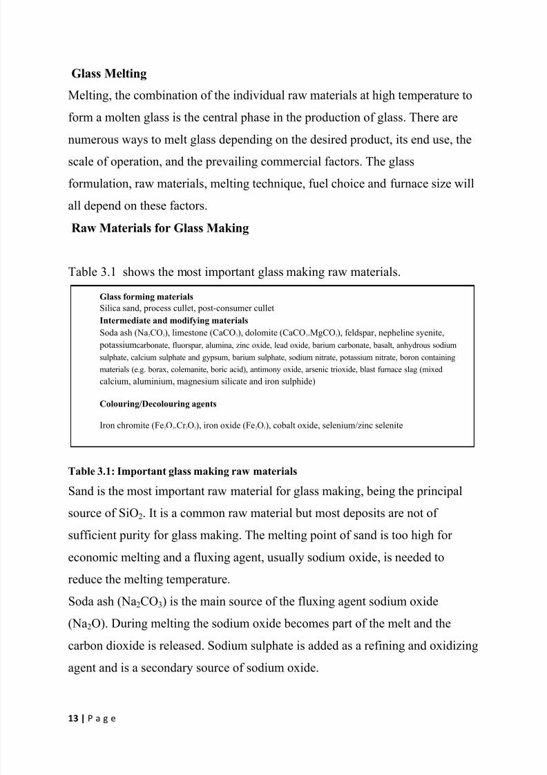
Glass forming materials
Silica sand, process cullet, post-consumer cullet
Intermediate and modifying materials
Soda ash (Na2CO3), limestone (CaCO3), dolomite (CaCO3.MgCO3), feldspar, nepheline syenite,
potassiumcarbonate, fluorspar, alumina, zinc oxide, lead oxide, barium carbonate, basalt, anhydrous sodium
sulphate, calcium sulphate and gypsum, barium sulphate, sodium nitrate, potassium nitrate, boron containing
materials (e.g. borax, colemanite, boric acid), antimony oxide, arsenic trioxide, blast furnace slag (mixed
calcium, aluminium, magnesium silicate and iron sulphide)
Colouring/Decolouring agents
Iron chromite (Fe2O3.Cr 2O3), iron oxide (Fe2O3), cobalt oxide, selenium/zinc selenite
Glass Melting
Melting, the combination of the individual raw materials at high temperature to
form a molten glass is the central phase in the production of glass. There are
numerous ways to melt glass depending on the desired product, its end use, the
scale of operation, and the prevailing commercial factors. The glass
formulation, raw materials, melting technique, fuel choice and furnace size will
all depend on these factors.
Raw Materials for Glass Making
Table 3.1 shows the most important glass making raw materials.
Table 3.1: Important glass making raw materials
Sand is the most important raw material for glass making, being the principal
source of SiO2. It is a common raw material but most deposits are not of
sufficient purity for glass making. The melting point of sand is too high for
economic melting and a fluxing agent, usually sodium oxide, is needed to
reduce the melting temperature.
Soda ash (Na2CO3) is the main source of the fluxing agent sodium oxide
(Na2O). During melting the sodium oxide becomes part of the melt and the
carbon dioxide is released. Sodium sulphate is added as a refining and oxidizing
agent and is a secondary source of sodium oxide.

8/10/2019 Glass as an Engineering material
http://slidepdf.com/reader/full/glass-as-an-engineering-material 14/44
14 | P a g e
The sodium oxide is incorporated into the glass and the sulphur oxide gases are
released through the melt. Potassium carbonate (K 2CO3) acts as a flux and is
used in some processes especially for special glass. The potassium oxide is
incorporated into the melt and the carbon dioxide is emitted.
Other metal oxides are added to the glass to reinforce the structural network to
improve the hardness and chemical resistance. Calcium oxide (CaO) has this
effect and is added to the glass as calcium carbonate (CaCO3) in the form of
limestone or chalk. It can also be added as dolomite, which contains both
calcium carbonate and magnesium carbonate (MgCO3).
Aluminium oxide (Al2O3) is added to improve chemical resistance and to
increase viscosity at lower temperatures. It is usually added as nepheline syenite
(Na2O.K 2O.Al2O3.SiO2), feldspar, or alumina, but is also present in blast
furnace slag and feldspatic sand. Lead oxides (PbO and Pb3O4) are used to
improve the sonority and to increase the refractive index of the glass to give
better brilliance in products such as lead crystal. Barium oxide (derived from
barium carbonate), zinc oxide, or potassium oxide may be used as alternativesto lead oxide, but they produce lower levels of density and brilliance than those
associated with lead crystal. There is also a penalty in the workability of
handmade glass.
Boron trioxide (B2O3) is essential in some products, particularly special glass
(borosilicate glasses) and in glass fibres (glass wool and continuous filaments).
The most important effect is the reduction of the glass expansion coefficient, but in fibres it also changes viscosity and liquidity to aid fiberisation, and
confers resistance to attack by water.
Fluoride containing materials (e.g. fluorspar CaF2) are used to make certain
products opaque. This is achieved by the formation of crystals in the glass,
which render it cloudy and opaque. Fluoride is also used in the continuous glass
filament sector to optimize surface tension and liquidity properties to aid
fiberisation and minimize filament breakage.
8/10/2019 Glass as an Engineering material
http://slidepdf.com/reader/full/glass-as-an-engineering-material 15/44
15 | P a g e
An increasingly important raw material in glass making is glass cullet, both in-
house cullet and external or foreign cullet. Virtually all processes recycle their
in-house cullet, but for some processes quality constraints mean it may not be
possible to secure a supply of foreign cullet of sufficient quality and consistency
to make its use economically viable. In the container glass sector cullet usage at
over 80 % of the batch is sometimes used. Cullet requires less energy to melt
than virgin raw materials, and every 1 tonne of cullet replaces approximately
1.2 tonnes of virgin material.
The Melting Process
The melting process is a complex combination of chemical reactions and
physical processes. This section only represents a brief summary of some of the
important aspects of the process. Melting can be divided into several phases
which all require very close control.
Heating The conventional and most common way of providing heat to melt glass is by
burning fossil fuels above a bath of batch material, which is continuously fed
into, and then withdrawn from the furnace in a molten condition. The
temperature necessary for melting and refining the glass depends on the precise
formulation, but is between 1300°C and 1550°C. At these temperatures heat
transfer is dominated by radiative transmission, in particular from the furnacecrown, which is heated by the flames to up to 1650 °C, but also from the flames
themselves. In each furnace design heat input is arranged to induce recirculating
convective currents within the melted batch materials to ensure consistent
homogeneity of the finished glass fed to the forming process. The mass of
molten glass contained in the furnace is held constant, and the mean residence
time is of the order of 24 hours of production for container furnaces and 72
hours for float glass furnaces.

8/10/2019 Glass as an Engineering material
http://slidepdf.com/reader/full/glass-as-an-engineering-material 16/44
16 | P a g e
Primary melting
Due to the low thermal conductivity of the batch materials the melting process
is initially quite slow allowing time for the numerous chemical and physical
processes to occur. As the materials heat up the moisture evaporates, some of
the raw materials decompose and the gases trapped in the raw materials escape.
The first reactions (decarbonisation) occur around 500°C. The raw materials
begin to melt between 750°C and 1200°C. First the sand begins to dissolve
under the influence of the fluxing agents. The silica from the sand combines
with the sodium oxide from the soda ash and with other batch materials to form
silicates. At the same time large amounts of gases escape through the
decomposition of the hydrates, carbonates, nitrates and sulphates; giving off
water, carbon dioxide, oxides of nitrogen, and oxides of sulphur. The glass melt
finally becomes transparent and the melting phase is completed. The volume of
the melt is about 35 - 50 % of the volume of the virgin batch materials due to
the loss of gases and the elimination of interstitial spaces.
Fining and Homogenization
The glass melt must be completely homogenized and free of bubbles before it
can be formed into the products. This involves the complete dissolution and
even distribution of all components and the elimination of all bubbles by
refining.During the melting process gas bubbles are formed mainly from carbon dioxide
given off by the decomposition of the carbonate materials (principally soda ash
and limestone) and to a much lesser extent from air trapped in the raw materials.
These bubbles must be eliminated from the glass melt as they potentially cause
defects in the finished product affecting mechanical strength and appearance.
The upward movement of bubbles contributes to the physical mixing of the melt
necessary to obtain a homogenous material with optimal physical properties.
8/10/2019 Glass as an Engineering material
http://slidepdf.com/reader/full/glass-as-an-engineering-material 17/44
17 | P a g e
The bubbles rise at speeds determined by their size and the viscosity of the
glass. Large bubbles rise quickly and contribute to mixing, while small bubbles
move slowly, at speeds that may be small with respect to the larger scale
convection currents in the furnace and are thus more difficult to eliminate.
Small bubbles remaining in the finished glass are termed "seeds". Carbon
dioxide and the components of air have limited solubility in the glass melt and it
is usually necessary to use chemical fining agents to effectively eliminate the
small bubbles generated by the melting process. The general principle of
chemical fining is to add materials which when in the melt will release gases
with the appropriate solubility in the glass. Depending on the solubility of the
gas in the glass melt (which is generally temperature dependent) the bubbles
may increase in size and rise to the surface or be completely reabsorbed. Small
bubbles have a high surface to volume ratio, which enables better exchange
between the gas contained in the bubbles and the glass.
The most frequently used fining agent in the glass industry is sodium sulphate.At approximately 1450°C (1200°C if reducing agents are present) the sodium
sulphate decomposes to give sodium oxide (which is incorporated into the
glass), gaseous oxides of sulphur, and oxygen. The oxygen bubbles combine
with or absorb other gases, particularly carbon dioxide and air, thereby
increasing in size and rising to the surface. The gaseous oxides of sulphur are
absorbed into the glass, or join the furnace waste gas stream.
In flat glass and container glass production sodium sulphate is by far the most
common fining agent. The predominance of sodium sulphate as the fining agent
is due to its parallel action as an oxidizing agent for adjusting the redox state of
the colouring elements in the glass. It is also the least expensive effective fining
agent for mass produced glass. Other fining agents include carbon materials and
oxides of arsenic and antimony. These are more expensive, have associated

8/10/2019 Glass as an Engineering material
http://slidepdf.com/reader/full/glass-as-an-engineering-material 18/44
18 | P a g e
environmental and health issues, and tend to be used mainly for the production
of special glass. Sodium nitrate can also be used as a fining/oxidizing agent
particularly if a high degree of oxidation is required. Calcium sulphate and
various nitrates are sometimes used for coloured flat glass.
Homogenization can also be aided by introducing bubbles of steam, oxygen,
nitrogen or more commonly air through equipment in the bottom of the tank.
This encourages circulation and mixing of the glass and improves heat transfer.
Some processes, for example optical glass, may use stirring mechanisms to
obtain the high degree of homogeneity required. Another technique for use in
small furnaces (especially special glass) is known as plaining; and involves
increasing the temperature of the glass so it becomes less viscous and the gas
bubbles can rise more easily to the surface.
The maximum crown temperatures encountered in glass furnaces are: container
glass 1600°C, flat glass 1620°C, special glass 1650°C, continuous filament
1650°C, and glass wool 1400°C.
Conditioning
A conditioning phase at lower temperatures follows the primary melting and
fining stages. During this process, all remaining soluble bubbles are reabsorbed
into the melt. At the same time, the melt cools slowly to a working temperature
between 900°C and 1350°C.
In batch melting, these steps occur in sequence, but in continuous furnaces themelting phases occur simultaneously in different locations within the tank. The
batch is fed at one end of the tank and flows through different zones in the tank
and fore hearth where primary melting, fining, and conditioning occur. The
refining process in a continuous furnace is far more delicate.
Glass does not flow through the tank in a straight line from the batch feeder to
the throat where the glass reaches the working temperature for processing. It is
diverted following thermal currents. The batch pile, or the cold mixture of raw

8/10/2019 Glass as an Engineering material
http://slidepdf.com/reader/full/glass-as-an-engineering-material 19/44
19 | P a g e
materials, is not only melted at the surface, but also from the underside by the
molten glass bath. Relatively cold, bubbly glass forms below the bottom layer
of batch material and sinks to the bottom of the tank. Appropriate convection
currents must bring this material to the surface, since fining occurs in tank
furnaces primarily at the surface of the melt, where bubbles need to rise only a
short distance to escape. If thermal currents flow too fast, they inhibit fining by
bringing the glass to the conditioning zone too soon. Guiding walls or weirs can
be built into the inner tank structure to create ideal glass flow paths.
Melting Techniques
Different techniques are used within the stone wool and frits sectors, and these
techniques are discussed separately within the specific sections for each sector.
As mentioned above the choice of melting technique will depend on many
factors but particularly the required capacity, the glass formulation, fuel prices,
existing infrastructure and environmental performance. For example, as a
general guide (to which there are inevitably exceptions):For large capacity installations (> 500 t/d) cross-fired regenerative furnaces are
almost always employed.
For medium capacity installations (100 to 500 t/d), regenerative end port
furnaces are favoured, though cross-fired regenerative, recuperative unit
melters, and in some cases oxy- fuel or electric melters may also be used
according to circumstances.For small capacity installations (25 to 100 t/d) recuperative unit melters,
regenerative end port furnaces, electric melters and oxy-fuel melters are
generally employed.
Glass furnaces are generally designed to melt large quantities of glass over a
continuous period of up to twelve years and range in output from 20 tonnes of
glass per day to over 600 tonnes of glass per day. The glass is contained in a
tank constructed of blocks of appropriate refractory materials and generally of
8/10/2019 Glass as an Engineering material
http://slidepdf.com/reader/full/glass-as-an-engineering-material 20/44
20 | P a g e
overall rectangular form closed by a vaulted ceiling or crown.
Electrical furnaces tend to be squarer with a flat ceiling and open on one side,
for batch access. The refractory blocks are maintained in position by an external
steel framework. There are many furnace designs in use, and they are usually
distinguished in terms of the method of heating, the combustion air preheating
system employed, and the burner positioning.
Glass making is a very energy intensive activity and the choice of energy
source, heating technique and heat recovery method are central to the design of
the furnace. The same choices are also some of the most important factors
affecting the environmental performance and energy efficiency of the melting
operation. The three main energy sources for glass making are natural gas, fuel
oil and electricity. In the first half of the century many glassmakers used
producer gas, made by the reactions of air and water with coal at incandescent
temperatures.
The use of natural gas is increasing in the Glass Industry due to its high purity,
ease of control and the fact that there is no requirement for storage facilities.Many companies are now using gas in preference to oil in order to reduce
emissions of sulphur dioxide even where there is a cost penalty.
In recent decades the predominant fuel for glass making has been fuel oil. There
are various grades from heavy to light, with varying purity and sulphur content.
The generally held opinion within the industry is that oil flames, being more
radiant than gas flames, give better heat transfer to the melt. As the industry hasdeveloped more experience with gas firing it is thought that the efficiency and
operational control achieved with gas firing is progressively approaching that of
oil firing.
Many large furnaces are equipped to run on both natural gas and fuel oil, with
only a straightforward change of burners being necessary. In many cases gas
supply contacts are negotiated on an interruptible basis during peak demand,
which necessitates the facility for fuel changeover. The main reason for the
8/10/2019 Glass as an Engineering material
http://slidepdf.com/reader/full/glass-as-an-engineering-material 21/44
21 | P a g e
periodic change between gas and fuel oil is the prevailing relative prices of the
fuels. In order to enhance control of the heat input, it is not uncommon for
predominantly gas-fired furnaces to burn oil on one or two ports.
The third common energy source for glass making is electricity. Electricity can
be used either as the exclusive energy source or in combination with fossil
fuels; this is described in more detail later. Electricity can be used to provide
energy in three basic ways: resistive heating, where a current is passed through
the molten glass; induction heating, where heat is induced by the change in a
surrounding magnetic field; and the use of heating elements. Resistive heating is
the only technique that has found commercial application within the Glass
Industry, and it is the only technique considered within this document.
Regenerative Furnaces
The term regenerative refers to the form of heat recovery system. Burners firing
fossil fuels are usually positioned in or below combustion air/waste gas ports.
The heat in the waste gases is used to preheat air prior to combustion. This is
achieved by passing the waste gases through a chamber containing refractorymaterial, which absorbs the heat. The furnace fires on only one of two sets of
burners at any one time. After a predetermined period, usually twenty minutes,
the firing cycle of the furnace is reversed and the combustion air is passed
through the chamber previously heated by the waste gases. A regenerative
furnace has two regenerator chambers, while one chamber is being heated by
waste gas from the combustion process; the other is preheating incomingcombustion air. Most glass container plants have either end-fired or cross-fired
regenerative furnaces, and all float glass furnaces are of cross-fired regenerative
design.
Preheat temperatures up to 1400 °C may be attained leading to very high
thermal efficiencies.
8/10/2019 Glass as an Engineering material
http://slidepdf.com/reader/full/glass-as-an-engineering-material 22/44
22 | P a g e
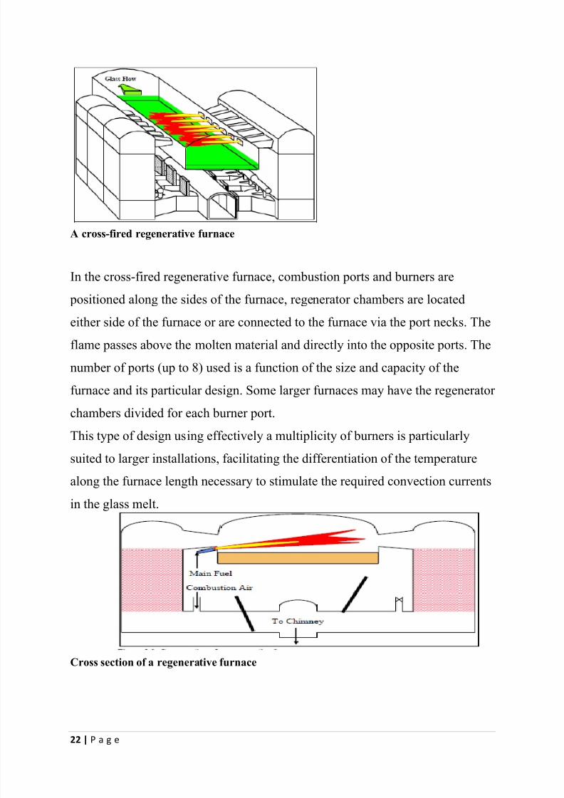
A cross-fired regenerative furnace
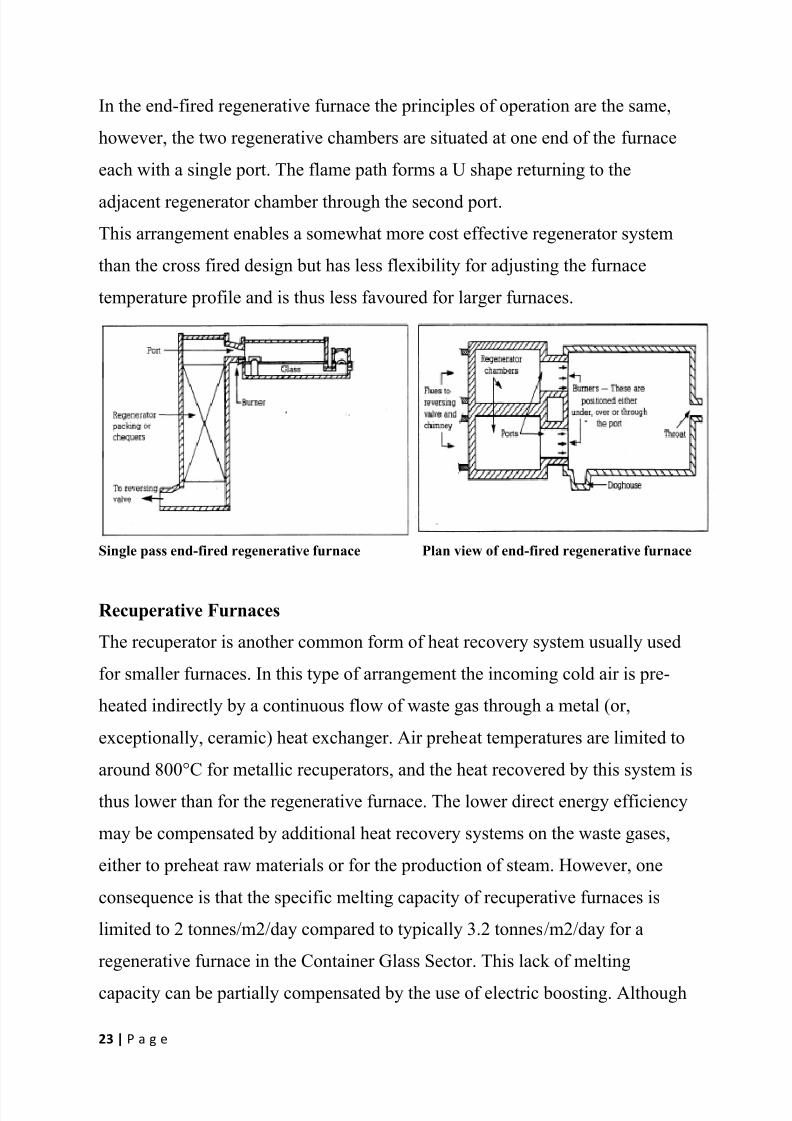
In the cross-fired regenerative furnace, combustion ports and burners are positioned along the sides of the furnace, regenerator chambers are located
either side of the furnace or are connected to the furnace via the port necks. The
flame passes above the molten material and directly into the opposite ports. The
number of ports (up to 8) used is a function of the size and capacity of the
furnace and its particular design. Some larger furnaces may have the regenerator
chambers divided for each burner port.This type of design using effectively a multiplicity of burners is particularly
suited to larger installations, facilitating the differentiation of the temperature
along the furnace length necessary to stimulate the required convection currents
in the glass melt.
Cross section of a regenerative furnace
8/10/2019 Glass as an Engineering material
http://slidepdf.com/reader/full/glass-as-an-engineering-material 23/44
23 | P a g e
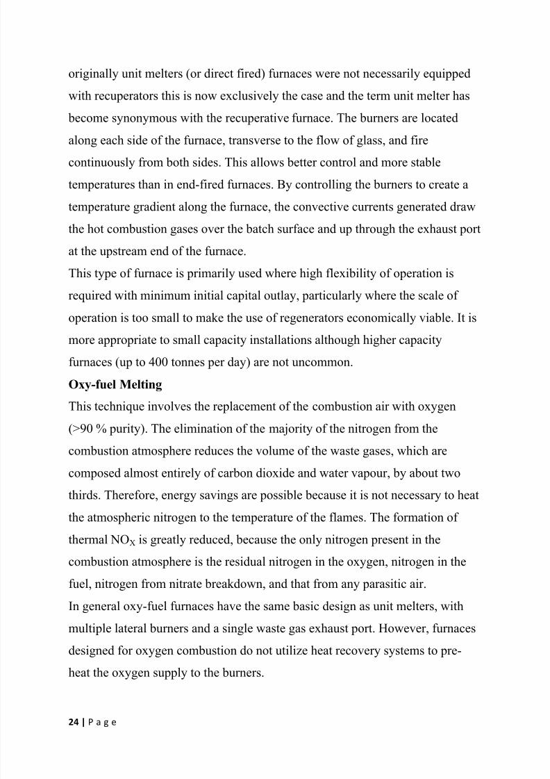
In the end-fired regenerative furnace the principles of operation are the same,
however, the two regenerative chambers are situated at one end of the furnace
each with a single port. The flame path forms a U shape returning to the
adjacent regenerator chamber through the second port.
This arrangement enables a somewhat more cost effective regenerator system
than the cross fired design but has less flexibility for adjusting the furnace
temperature profile and is thus less favoured for larger furnaces.
Single pass end-fired regenerative furnace Plan view of end-fired regenerative furnace
Recuperative Furnaces
The recuperator is another common form of heat recovery system usually used
for smaller furnaces. In this type of arrangement the incoming cold air is pre-
heated indirectly by a continuous flow of waste gas through a metal (or,
exceptionally, ceramic) heat exchanger. Air preheat temperatures are limited to
around 800°C for metallic recuperators, and the heat recovered by this system is
thus lower than for the regenerative furnace. The lower direct energy efficiency
may be compensated by additional heat recovery systems on the waste gases,
either to preheat raw materials or for the production of steam. However, one
consequence is that the specific melting capacity of recuperative furnaces is
limited to 2 tonnes/m2/day compared to typically 3.2 tonnes/m2/day for a
regenerative furnace in the Container Glass Sector. This lack of melting
capacity can be partially compensated by the use of electric boosting. Although
8/10/2019 Glass as an Engineering material
http://slidepdf.com/reader/full/glass-as-an-engineering-material 24/44
24 | P a g e
originally unit melters (or direct fired) furnaces were not necessarily equipped
with recuperators this is now exclusively the case and the term unit melter has
become synonymous with the recuperative furnace. The burners are located
along each side of the furnace, transverse to the flow of glass, and fire
continuously from both sides. This allows better control and more stable
temperatures than in end-fired furnaces. By controlling the burners to create a
temperature gradient along the furnace, the convective currents generated draw
the hot combustion gases over the batch surface and up through the exhaust port
at the upstream end of the furnace.
This type of furnace is primarily used where high flexibility of operation is
required with minimum initial capital outlay, particularly where the scale of
operation is too small to make the use of regenerators economically viable. It is
more appropriate to small capacity installations although higher capacity
furnaces (up to 400 tonnes per day) are not uncommon.
Oxy-fuel Melting
This technique involves the replacement of the combustion air with oxygen(>90 % purity). The elimination of the majority of the nitrogen from the
combustion atmosphere reduces the volume of the waste gases, which are
composed almost entirely of carbon dioxide and water vapour, by about two
thirds. Therefore, energy savings are possible because it is not necessary to heat
the atmospheric nitrogen to the temperature of the flames. The formation of
thermal NOX is greatly reduced, because the only nitrogen present in thecombustion atmosphere is the residual nitrogen in the oxygen, nitrogen in the
fuel, nitrogen from nitrate breakdown, and that from any parasitic air.
In general oxy-fuel furnaces have the same basic design as unit melters, with
multiple lateral burners and a single waste gas exhaust port. However, furnaces
designed for oxygen combustion do not utilize heat recovery systems to pre-
heat the oxygen supply to the burners.

8/10/2019 Glass as an Engineering material
http://slidepdf.com/reader/full/glass-as-an-engineering-material 25/44
25 | P a g e
The principle of oxy-fuel furnaces is well established, particularly in the frits
sector. The technique is still considered by some sectors of the glass industry, as
a developing technology with potentially high financial risk. However,
considerable development work is being undertaken and the technique is
becoming more widely accepted as the number of plants is increasing.
Electric Melting
An electric furnace consists of a refractory lined box supported by a steel frame,
with electrodes inserted either from the side, the top or more usually the bottom
of the furnace. The energy for melting is provided by resistive heating as the
current passes through the molten glass. It is, however, necessary to use fossil
fuels when the furnace is started up at the beginning of each campaign. The
furnace is operated continuously and has a lifetime of between 2 and 7 years.
The top of the molten glass is covered by a layer of batch material, which
gradually melts from the bottom upwards, hence the term cold top melter. Fresh
batch material is added to the top of the furnace, usually by a conveyor system
that moves across the whole surface. Most electric furnaces are fitted with bagfilter systems and the collected material is recycled to the melter.
The technique is commonly applied in small furnaces particularly for special
glass. The main reason for this is the thermal efficiency of fossil fuel fired
furnaces decreases with furnace size and heat losses per tonne of melt from
small furnaces can be quite high. Heat losses from electric furnaces are much
lower in comparison and for smaller furnaces the difference in melting costs between electrical and fossil fuel heating is therefore less than for larger
furnaces.
Other advantages of electric melting for small furnaces include lower rebuild
costs, comparative ease of operation and better environmental performance.
There is an upper size limit to the economic viability of electric furnaces, which
is closely related to the prevailing cost of electricity compared with fossil fuels.
Electric furnaces can usually achieve higher melt rates per square metre of
8/10/2019 Glass as an Engineering material
http://slidepdf.com/reader/full/glass-as-an-engineering-material 26/44
26 | P a g e
furnace, and the thermal efficiency of electric furnaces is two to three times
higher than fossil fuel fired furnaces. However, for larger furnaces this is often
not sufficient to compensate for the higher costs of electricity.
The absence of combustion in electric melting means that the waste gas
volumes are extremely low; resulting in low particulate carries over and reduced
size of any secondary abatement equipment. The emission of volatile batch
components is considerably lower than in conventional furnaces due to the
reduced gas flow and the absorption and reaction of gaseous emissions in the
batch blanket. The main gaseous emission is carbon dioxide from the
carbonaceous batch materials.
The complete replacement of fossil fuels in the furnace eliminates the formation
of combustion products, namely sulphur dioxide, thermal NO2, and carbon
dioxide. However, if a global view is taken these benefits should be considered
against the releases arising at the power generation plant, and the efficiencies of
power generation and distribution.
A complication with electric melting is the use of sodium nitrate or potassiumnitrate in the batch. The general view of the glass industry is that nitrate is
required in cold-top electric furnaces to provide the necessary oxidizing
conditions for a stable, safe and efficient manufacturing process. The problem
with nitrate is that it breaks down in the furnace to release oxides of nitrogen,
but at levels lower than those associated with conventional fossil fuel firing.
Combined Fossil Fuel and Electric MeltingThere are two principal approaches to the use of this technique: predominantly
fossil fuel firing with electric boost; or predominantly electrical heating with a
fossil fuel support. Clearly the proportion of each type of heat input can be
varied with each technique.
Electric boosting is a method of adding extra heat to a glass furnace by passing
an electric current through electrodes in the bottom of the tank. The technique is
commonly used within fossil fuel fired furnaces in the Glass Industry.
8/10/2019 Glass as an Engineering material
http://slidepdf.com/reader/full/glass-as-an-engineering-material 27/44
27 | P a g e
Traditionally, it is used to increase the throughput of a fossil fuel fired furnace
to meet periodic fluctuations in demand, without incurring the fixed costs of
operating a larger furnace. The technique can be installed while a furnace is
running, and it is often used to support the pull rate of a furnace as it nears the
end of its operating life or to increase the capacity of an existing furnace.
Electric boosting can also be used to improve the environmental performance of
the furnace by substituting electrical heating for combustion for a given glass
pull rate. Usually 5 % to 20 % of total energy input would be provided by
electric boost although higher figures can be achieved.
However, a high level of electric boost is not used as a long-term option for
base level production due to the associated high operating costs. Variable levels
of electric boost are frequently used in coloured glass due to the poor radiant
heat transfer in green and amber glass.
A less common technique is the use of gas or oil as a support fuel for a
principally electrically heated furnace. This simply involves firing flames over
the surface of the batch material to add heat to the materials and aid melting.The technique is sometimes referred to as over-firing and is often used to
overcome some of the operational difficulties encountered with 100 % electric
melting. Clearly the technique reduces some of the environmental benefits
associated with combustion free cold top melting.
Discontinuous Batch Melting
Where smaller amounts of glass are required, particularly if the glassformulation changes regularly, it can be uneconomical to operate a continuous
furnace. In these instances pot furnaces or day tanks are used to melt specific
batches of raw material. Most glass processes of this type would not fall under
the control of IPPC because they are likely to be less than 20 tonnes per day
melting capacity. However, there are a number of examples in domestic glass
and special glass where capacities above this level exist, particularly where
more than one operation is carried out at the same installation.
8/10/2019 Glass as an Engineering material
http://slidepdf.com/reader/full/glass-as-an-engineering-material 28/44
28 | P a g e
A pot furnace is usually made of refractory brick for the inner walls, silica brick
for the vaulted crown and insulating brick for the outer walls. Basically a pot
furnace consists of a lower section to preheat the combustion air (either a
regenerative or a recuperative system), and an upper section which holds the
pots and serves as the melting chamber. The upper section holds six to twelve
refractory clay pots, in which different types of glass can be melted.
There are two types of pots open pots and closed pots. Open pots have no tops
and the glass is open to the atmosphere of the furnace. Closed pots are enclosed
and the only opening is through the gathering hole. With open pots the
temperature is controlled by adjusting furnace firing, with closed pots firing is
at a constant rate, and the temperature is controlled by opening or closing the
gathering hole. The capacity of each pot is usually in the range 100 kg to 500
kg, with a lifetime of 2 to 3 months under continuous operation.
The furnace is heated for 24 hours each day but the temperature varies (glass
temperature only for closed pots) according to the phase of the production cycle.
Generally, the batch is loaded into the pots and melted in the afternoon, and thetemperature is increased overnight to refine the melt so the glass can be
processed the next morning. During melting the temperature climbs to between
1300°C and 1600°C, depending on the glass type, and during the removal and
processing of the glass the furnace temperature is in the range 900°C to 1200°C.
Day tanks are further developed from pot furnaces to have larger capacities, in
the region of 10 tonnes per day. Structurally they more closely resemble thequadrangle of a conventional furnace, but are still refilled with batch each day.
The melting is usually done at night and the glass goes into production the next
day. They allow a change in glass type to be melted at short notice and are
primarily used for coloured glass, crystal glass and soft special glasses.
8/10/2019 Glass as an Engineering material
http://slidepdf.com/reader/full/glass-as-an-engineering-material 29/44
29 | P a g e
Special Melter Designs
The attention paid to limiting NOX emissions has led some furnace designers to
propose unit melter type furnaces that integrate various features intended to
permit lower flame temperatures. The best known of this type of furnace is the
Sorg LoNOx melter.
The Sorg LoNOx melter uses a combination of shallow bath refining and raw
material preheating to achieve reduced NOx levels, potentially without the
penalty of reduced thermal performance. The shallow bath refiner forces the
important critical current path close to the surface of the glass bath, thereby
reducing the temperature differential between it and the furnace superstructure.
The furnace can be operated at lower temperatures than a comparable
conventional furnace.
Another new furnace design is the Sorg Flex Melter, which is principally
marketed as an alternative to pot furnaces and day tanks. It uses a combination
of electricity and natural gas resulting in a compact furnace with low operating
temperatures and low energy consumption.The furnace is divided into melting and refining zones, which are connected by
a throat. The refining area consists of a shallow bank followed by a deeper area.
The melting end is electrically heated and the refining zone is gas heated, but
electrodes may be added at the entrance. The waste gases from the refining zone
pass through the melting area and over the batch. A number of low arches
prevent radiation from the hotter part of the furnace reaching the colder areas,so that a large part of the energy in the waste gases is transferred to the batch.
The separation of the melting and refining zones is the basis of the furnace‟s
flexibility. During standstill periods temperatures are lowered and volatilization
from refining is reduced. No drain is needed and due to the low glass volume,
normal operating temperature is re-established quickly. The low volume also
helps to make faster composition changes.

8/10/2019 Glass as an Engineering material
http://slidepdf.com/reader/full/glass-as-an-engineering-material 30/44
30 | P a g e
CHAPTER FOUR
PROBLEMS EXPERIENCED IN GLASS MAKING
The production of glass and its use poses a large number of problems. Some of
those problems are quite generic in nature, others more typical for glass
industry as such. Involvement of mathematicians to solve these
problems should prove to be an important key to success here too. Below we
give a number of examples of such problems.
Heat transfer. An important parameter for the production of glass and
glassware is the temperature. Almost all production steps are influenced
by the temperature distribution within the glass. Thus, heat
exchange is an important mechanism in morphological processes. It
turns out that heat exchange through radiation is strongly dominating
convective and diffusive effects at higher temperatures, which is the
relevant situation. This radiation is modeled by a deceivingly
simple transport equation. Only when the material is optically thick this
can be tackled in a simple way. However, glass products are usuallyoptically thin and one has to take recourse to methods like ray tracing.
These methods, on the other hand, are computationally
prohibitively expensive, if used straightforwardly. Both a better analysis
of the model and the equations and numerically efficient methods are
required here. The industry is waiting for a breakthrough as most
processes depend critically on appropriate knowledge of thisradiation.
Forming of Glass: Glass products are usually formed by pressing or
blowing (of hot glass). The rheological properties determine the flow in
such process in a dramatically way (viscosity). As a consequence, the
various parameters in this process (form of the mold, temperature control,
velocity etc.) need mathematical modeling. Only adequate simulation can
help optimizing the process; in fact, experimental design would be too

8/10/2019 Glass as an Engineering material
http://slidepdf.com/reader/full/glass-as-an-engineering-material 31/44
31 | P a g e
costly as it is based on trial and error. Mathematically the area requires
modeling by inverse problems, boundary layer analysis and large scale
computing. The results will be equally useful in areas like injection
molding for polymers.
Sick/Slip and contact problems: Contact problems between glass melt
and mold occur for instance during forming and processing of
hot glass. Due to different thermal expansion behaviour of the glass
melt and the mold, buckling or rippling effects during forming can be
observed. Until now these processes haven‟t been modeled satisfactorily.
The understanding of these problems is very important for the
right simulation of the whole glass processing. Similar problems arise for
casting materials like steel.
Parameter identification and shape optimization: The knowledge of the
right material parameters (for instance: the heat transfer coefficient
during cooling of glass or relaxation parameters for deformation
processes) is one of the fundamental engineering problems. Oftenit is not possible to measure these parameters directly. They have to be
determined indirectly by other parameters. As an example we mention
spectral remote sensing, where the temperature distribution inside hot
glasses will be reconstructed using measured spectral intensity data. In
general these problems are ill-posed: small perturbations of the measured
data give large errors in the reconstruction of the interested parameter. Flux Line Corrosion: Glass melting furnaces are expensive to build (say
100 million euros), and the lifetime between major repairs (at least 10
million euros and a couple of months out of production) is important.
Corrosion of the sidewalls by the molten glass is one of the major factors
limiting the furnace life. The corrosion occurs primarily towards the top
surface. This may be driven by prevailing temperature gradients, or by
the density change brought about by the corrosion products. The first
8/10/2019 Glass as an Engineering material
http://slidepdf.com/reader/full/glass-as-an-engineering-material 32/44
32 | P a g e
case, and to a considerable extent even the second, can be studied by well
understood analytical and/or computational techniques. It appears that the
effects of the corrosion products on surface tension are important. These
surface tension effects also drive a flow, very close to the ripple point, or
flux line, and on a length scale of the order of the meniscus. There is a lot
more to do, and the mathematics of the attack of liquids on solids due
primarily to surface tension driven flows is a matter of much wider
importance.
Thin turbulence in sheet glass: For the production of float glass the liquid
glass melt is directed on a tin bath. To predict the shape, thickness, and
the temperature distribution of the glass, an efficient coupling of the glass
model and the tin bath model is needed. A standard way to model the
interface between glass and tin is to use thin boundary layer analysis. On
the other side large temperature gradients in the tin bath lead to turbulent
flows. A mathematical model and efficient numerical methods, which
take into account these three-dimensional effects, are of industrial as wellas of theoretical interest.
Windscreen sag bending : A widely used and inexpensive method
of manufacturing laminated glass (for car windscreens, for example) is by
gravity sag bending. A sheet of glass is placed on a frame and unequally
heated in a controlled fashion so that it sags under its own weight toward
a certain target shape. However, problems typically develop at the corners(lift-off of the sheet from the frame, unwanted changes of curvatures that
produce undesirable optical effects) and at the center of the sheet.
Research is required toward a better mathematical modeling of the
process. This problem can be seen both as a shape optimization and as an
inverse problem. Preliminary numerical studies show that this problem
is ill-posed and needs appropriate regularization methods for its
stable solution.

8/10/2019 Glass as an Engineering material
http://slidepdf.com/reader/full/glass-as-an-engineering-material 33/44
33 | P a g e
Foam: The chemical reactions in the raw material in the batch produce
foam. In order to study this phenomenon one needs to understand the
mechanisms that produce the bubbles and push them around. Apparently
the foam layer consists of lighter material that slides over the bath. One
e.g. needs to study what horizontal stress this layer applies to the bath, as
it changes the flow there. The flow of the glass takes smaller bubbles,
which may eventually dissolve. For the foam layer one should understand
how the bubbles arrive, go away, coalesce or burst. An important
question is whether it is possible to control how much of bath is covered.
There is a major interference with radiative heat transfer from the
refractory. Further problems are how to model the input of raw materials,
how heat gets in, from top and bottom, how reactions take place and how
reactions change the heat transfer.
Refractory and combustion: The refractory is a combination of three
tough problems. First the flow is turbulent, and compressible. Second
there is the chemistry. One needs to model the amount of mixing of thefuel and the oxidant by the turbulent flow. The chemical reaction is often
typically handled by a single reacting species, which certainly cannot
work for estimates of No2 production. Third on has to model the radiative
heat transfer. Often a grey-gas approximation is used, say as in FLUENT,
but for a realistic approach one needs more sophisticated radiation
methods. An important aspect is the effect of the heat transfer through thewalls (their thickness), and the effect of the height of the refractory on the
complex interacting physics. Another big problem is the lifetime of a
furnace - can it be increased from 8 to 10 years? By what design and
running changes?
Feeder/gob-forming : The glass coming out of the oven is handled by a so
called gobber, a device that produces gobs of glass for the eventual
pressing. This cutting may e.g. leave a scar on the gob for TV screens,
8/10/2019 Glass as an Engineering material
http://slidepdf.com/reader/full/glass-as-an-engineering-material 34/44
34 | P a g e
even such that further processing is required (like polishing). For
container glass it is responsible for asymmetric shapes in bottles. In either
case a better understanding of the process may improve quality of the end
product and make the production cheaper, for instance because a higher
percentage of products is immediately acceptable. Another question is the
heat exchange in the feeder. Since the effectivity of a pressing or blowing
process is highly dependent on the proper temperature the heat exchange
needs to be controlled.
PROSPECTS OF GLASS MAKING
EMERGING TECHNIQUES
The Glass Industry can be very innovative in its products and applications,
especially in the low volume, high value areas of the industry. The innovations
in the melting operations tend to be more gradual and incremental, and are
sometimes based on the adaptation of existing concepts.
The investments in glass furnaces are substantial and modifications are difficult before the next rebuild. If problems occur during the campaign lost production
time and repairs can be very costly, especially if the furnace has to be allowed
to cool. Therefore, major modifications carry quite a high risk and companies
need to be quite confident of performance before they implement new designs
and technology. Similarly the effects of any new technology can only be fully
assessed over the period of a full campaign.The increasing pressure to improve environmental performance has proven to
be a strong stimulus for innovation, particularly in developing alternatives to
potentially expensive conventional secondary abatement equipment. For
example:
The 3R process was developed from the chemical reduction by fuel
principle, which has been conventionally used in large combustion plants.
Although it is based on the adaptation of an existing principle, substantial
8/10/2019 Glass as an Engineering material
http://slidepdf.com/reader/full/glass-as-an-engineering-material 35/44
35 | P a g e
development and innovation was required to apply the principle
successfully to glass furnaces.
The FENIX system is an optimization of the combustion conditions in the
furnace based on burner modifications and a detailed knowledge of the
factors that affect NO2 formation and how they interact in the furnace
environment.
Low NO2 burner systems that were originally developed for other
applications have been modified specifically for glass furnaces.
The Sorg LoNOx melter is an innovative redesign of a conventional glass
furnace to minimize NO2 formation and maximize heat recovery.
There are no major breakthroughs in technology expected in the medium term,
but a number of techniques are undergoing constant developments to optimize
their benefits, which may make them more attractive to industry in the long
term. There are also a number of completely new concepts under development,
but these are not expected to find application in the industry within the
foreseeable future.
Briefly discussed are those techniques that are available and cannot be
considered as emerging but which are likely to undergo further developments,
and also those more innovative long-term techniques that are still at pilot scale.
Low NOx Burner Systems
New burner systems are still undergoing developments and further incremental
advances can be anticipated. The application of these new burners combinedwith advanced combustion control methods, using exhaust gas analytical
methods shows a potential for further reduction in NO2 formation. Also furnaces
are being designed to optimize the geometry to the new combustion systems.
However, there are some technological issues to be considered as the
developments continue, for example:
there is a potential risk of refractory damage by the reducing parts offlames touching the combustion chamber refractories; and
8/10/2019 Glass as an Engineering material
http://slidepdf.com/reader/full/glass-as-an-engineering-material 36/44
36 | P a g e
the reducing conditions above the melt or batch blanket could affect glass
quality and may
Cause early sulphate decomposition requiring extra sulphate to be added
to assure complete fining, which may lead to increased SO2 emissions.
Batch Formulations
There are currently a number of interesting developments regarding batch
formulation and these are summarized below;
Glass formulations that, in combination with other techniques, reduce dust
emissions are being developed within the soda-lime glass sectors of the Glass
Industry. It is claimed that emission levels in the range 70 - 100 mg/m3 could be
possible in many applications.
In Germany and the Netherlands research projects have been initiated for the
development of new selenium raw materials with a lower volatility and an
improved decolorizing efficiency.
Application of these new selenium raw materials could limit selenium emissions
in the future during production of tableware and flint glass. No further
information is currently available.
A new glass composition for continuous filament glass fibre has been developed
by one producer. This glass composition addresses two main air emission
components typical of Eglass melting i.e. particulates and fluorides. This glass
composition does not include boron or added fluorine. The fluoride emission
reduction is due to the fact that, having no added fluorides in the glasscomposition, fluoride emissions are limited to the tramp fluorides present in raw
materials, resulting in fluoride emissions below 50 mg/m3. The particulate
formation mechanism in standard E-glass formulations is governed by the
volatilization of borate species. Over 85 % of the particulate matter emitted
from the furnace is related to boron and the removal of the borate species from
the glass results in a substantial reduction in particulate formation to generally
below 50 mg/m3.
8/10/2019 Glass as an Engineering material
http://slidepdf.com/reader/full/glass-as-an-engineering-material 37/44
37 | P a g e
The elimination of boron and added fluoride render this glass more difficult to
melt (higher melting temperature) and to fiberise, and can lead to some increase
in energy requirements.
More experience is necessary to determine the long term resistance of furnace
refractories. The implementation of this glass formulation also requires the
qualification of the various product types and modifications to the melting and
forming operations. It is, however, considered as a promising route to achieve
significant emission reductions by primary means. This technique has been
developed by one company and is covered by patents, and therefore is not
generally available within the sector.
New Melter Designs
The Seg-Melter
The segmented melting concept seeks to capitalize on the different melting
requirements of the two main raw materials used in container glass
manufacture, batch and cullet. Pure batch is melted at approximately 1400°C
with a dwell time of 24 hours, while cullet requires a melting temperature ofonly 1100°C and a dwell time of 1 - 2 hours.
Batch is charged into an all-electric pre-melting furnace capable of converting
75 % of the raw material into glass. The pre-melted batch then moves via a
throat into an enlarged doghouse where cullet is added (cullet comprises at least
60 % of the raw material). The batch/cullet mix then enters the second melting
chamber. This is gas or oil-fired, uses oxy-fuel burners, and has a glass depthwhich is less than that of the pre-melting section.
The system potentially offers a number of advantages:
emissions during the all-electric pre-melt stage are almost eliminated;
fuel consumption in the second melting chamber is lower because cullet
melts at a lower temperature than the batch;
the use of oxy-fuel burners minimizes NOx emissions from the second
melting chamber;

8/10/2019 Glass as an Engineering material
http://slidepdf.com/reader/full/glass-as-an-engineering-material 38/44
38 | P a g e
The second melting chamber can be smaller in size because of the
reduced dwell time required.
For a 230 tonne/day furnace converted to a Seg-melter, thermal efficiencies are
more than 25 % higher than those achieved using conventional melting.
Maintenance requirements, however, can be higher. Although a complete
campaign has been estimated at 15 years, the electric melting section of the Seg-
melter is expected to require repairs approximately every three years, with the
fuel-fired section continuing to operate at reduced load.
The Advanced Glass Melter
The Advanced Glass Melter (AGM), which is currently under development,
employs a totally different concept for batch pre-heating and melting. Batch
materials are injected into the reaction zone of the flame in a natural gas-fired
combuster. Rapid heating occurs while the materials are in suspension, and both
the products of combustion and the heated batch materials are then discharged
via a high velocity nozzle into the melt chamber and on to a “centre body”, off
which the molten glass flows into a reservoir. Because the flame temperature isquenched by the presence of the batch in the flame, one major advantage of this
system is its potential for low NOx emissions.
The Plasma Melter
The British Glass Research Group is currently developing a rapid melting
process, which makes use of the electrical conductivity of molten glass. The
system comprises three electric arc torches positioned at 120 ºC to one another.These are fed with a supply of high purity argon gas that is ionised and forced
out of the torch nozzles in the form of a low energy plasma flame. An insulating
crucible containing molten glass is situated below the torches. Batch or cullet is
fed into this melting bath from above, while molten glass is continuously drawn
from the base.
The system can operate as either a pre-melter or a final melter. Pre-melting on
non-conducting glass cullet and batch is achieved when the torches are brought
8/10/2019 Glass as an Engineering material
http://slidepdf.com/reader/full/glass-as-an-engineering-material 39/44
39 | P a g e
into close proximity. Current is transferred from one torch to another through
the ionised plasma jet, and convective heat from the expanding gas and radiative
heat from the plasma combine to create a molten pool of glass.
In final melting mode the torches are repositioned so that the plasma current
flows from torch to torch via the molten glass. The resistance of glass is
sufficiently low at these high temperatures to permit this mode of operation.
The system offers a number of potential benefits:
batch and cullet can be melted in minutes to produce partly refined glass;
the furnace can be turned on and off at will;
the composition and colour of the glass can very rapidly be altered;
Operation is virtually pollution free - SOx, NOx and dust emissions are
negligible.
This type of melting could be available for very small-volume melts within the
next few years.
It is not expected to be a viable technique for melting more than 20 tonnes a day
within the foreseeable future.

8/10/2019 Glass as an Engineering material
http://slidepdf.com/reader/full/glass-as-an-engineering-material 40/44
40 | P a g e
8/10/2019 Glass as an Engineering material
http://slidepdf.com/reader/full/glass-as-an-engineering-material 41/44
41 | P a g e
CONCLUSION
It was very clear from the beginning of this term paper that the Glass Industry
as identified is extremely diverse, both in scale and the technologies used. One
of the most important conclusions is that due to this diversity it is often
inappropriate to specify particular techniques to be applied as Best Available
Techniques (BAT) across all processes and sectors. The general approach taken
in this term paper is to identify levels of performance which are indicative of the
use of BAT and then to identify those techniques which are most likely to be
appropriate for a given sector. Throughout it is acknowledged that the most
appropriate way of achieving these performance levels can differ from process
to process.
A great deal has been achieved in recent years to improve the environmental
performance of the industry. This trend is continuing and further improvements
are expected. As explained, improvements in performance are anticipated from
the further development of primary techniques and more conventional
secondary techniques, rather than completely novel new techniques.As the expectations and requirements for environmental performance increase,
the industry is faced with potentially high costs of compliance. This provides an
incentive for industry to develop more cost-effective methods of achieving these
performance levels and the Glass Industry has been quite successful in meeting
this challenge. The most cost-effective techniques are often primary techniques,
which prevent the emission of pollutants rather than treating the substancesemitted. When considering the overall impact on the environment, primary
techniques are generally preferable where they can achieve equivalent emission
levels.
Particular successes have been with the use of primary techniques, including
oxy-fuel firing, to control emissions of NOx. However, for particulate emissions
primary techniques are not generally capable of achieving emission levels
comparable to secondary techniques.
8/10/2019 Glass as an Engineering material
http://slidepdf.com/reader/full/glass-as-an-engineering-material 42/44
42 | P a g e
REFERENCES
Directive 96/61/EC concerning integrated pollution prevention and control
(10/10/96)
Pollution Control at Large Glass Works, UK Department of the Environment,
Environmental Resources Limited, March 1991.
3R Process, NOX Control Technology from Pilkington, Pilkington company
publication, September 1994.
Alternative Control Techniques Document – NOX Emissions from Glass
Manufacturing, United States Environmental Protection Agency, June 1994.
Verein Deutscher Ingenieure Guidelines (VDI 2578) Emission Control
Glassworks, 1988.
Energy Efficient Environmental Control in the Glass Industry, Good Practice
Guide 127, UK Energy Efficiency Office, 1995.
Reduction des Emissions d‟Oxydes d‟Azote dans L‟Industrie du Verre, Comité
de Suivi du Verre, Arrêté du 14 mai 1993, July 1996.
Technical and Economic Review of Technique to Control Emissions from Non-
asbestos mineral fibres and Frit Manufacturing Processes, Environment Agency
(England and Wales), August 1996.

8/10/2019 Glass as an Engineering material
http://slidepdf.com/reader/full/glass-as-an-engineering-material 43/44
43 | P a g e
IPC Guidance Note S2 3.03, Manufacture of glass fibres, other non-asbestos
mineral fibres, glass frit, enamel frit and associated processes, Environment
Agency, HMSO, September 1996,
BATNEEC Guidance Note – Glass Production (Draft), Irish Environmental
Protection Agency, 1996.
BATNEEC Guidance Note – Manufacture of Glass Fibre or Mineral Fibre
(Draft), Irish Environmental Protection Agency, 1996,
Prévention et traitement des émissions d‟oxydes de soufre, Actes du Colloque,
Colloque National, 4 et 5 Dé1997, Le Havre.
Les techniques de desulfuration des procedes industriels (Draft Version) 1998.
CGCRI Training Manual 1993 in Wear resistant ceramic coatings
for industrial and engineering application (Calcutta: CGCRI)
Dutta S 1998 Bull . Mater . Sci.
Hennicke H W and Pandel A 1991 The Vitreous Enameller
Pevzner B Z, Dzhavuktsyan S G and Mishel V E 1972 Glass & Ceramics
Schmid T E and Heeht 1988 Ceram. Engg . Proc.
Sen R, Dutta S, Das S K and Basu S K 1989 Wear
Shaw K 1968 Technology of Enamels (ed. & Trans.) V V

8/10/2019 Glass as an Engineering material
http://slidepdf.com/reader/full/glass-as-an-engineering-material 44/44
Vargin (London: Maclaren & Sons Ltd.) pp. 179 – 181, 183, 197 – 202, 204 – 206
Tong J, Zhang M, Jian M and Ren L 1998 J. Mater. Sci. Lett .
Vargin V V and Zasukhina L Z 1972 Glass & Ceramics
Zubekhin A P, Thachev A G and Thacheva O N 1996 Glass & Ceramics