Embed Size (px)
Citation preview
Corrosion Science 82 (2014) 316–327
Contents lists available at ScienceDirect
Corrosion Science
journal homepage: www.elsevier .com/locate /corsc i
Glass coatings on stainless steels for high-temperature oxidationprotection: Mechanisms
http://dx.doi.org/10.1016/j.corsci.2014.01.0330010-938X/� 2014 Elsevier Ltd. All rights reserved.
⇑ Corresponding author. Tel.: +86 24 23904856; fax: +86 24 23893624.E-mail address: [email protected] (M. Chen).
Minghui Chen ⇑, Wenbo Li, Mingli Shen, Shenglong Zhu, Fuhui WangState Key Laboratory for Corrosion and Protection, Institute of Metal Research, Chinese Academy of Sciences, Shenyang 110016, China
a r t i c l e i n f o
Article history:Received 8 July 2013Accepted 24 January 2014Available online 31 January 2014
Keywords:A. Stainless steelA. GlassC. OxidationC. Interfaces
a b s t r a c t
The oxidation behavior of a martensitic stainless steel with or without glass coating was investigated at600–800 �C. The glass coating provided effective protection for the stainless steel against high-tempera-ture oxidation. However, it follows different protection mechanisms depending on oxidation tempera-ture. At 800 �C, glass coating acts as a barrier for oxygen diffusion, and oxidation of the glass coatedsteel follows linear law. At 700 or 600 �C, glass coating induces the formation of a (Cr,Fe)2O3/glasscomposite interlayer, through which the diffusion of Cr3+ or Fe3+ is dramatically limited. Oxidation fol-lows parabolic law.
� 2014 Elsevier Ltd. All rights reserved.
1. Introduction
Glasses or glass–ceramics with good compatibility to certainmetal substrates show good prospect to be used as coating materi-als for high-temperature corrosion protection [1–3]. It iswell-known that glasses can easily form hermetic seals to the alloysubstrates and insulate them from corrosive media. In addition tothe superior high resistance to compressive stresses and chemicalattack, glass coatings stand out with the ease of processing [4–8].By controlling crystallization of the parent glasses or incorporationof a second phase (metals or ceramics), the thermophysical proper-ties of the glass matrix composite coatings would be tailored in awide range to match better with the alloy substrates [9,10].
The protection mechanisms of glass coatings for titanium alloyand superalloy substrates against high-temperature oxidation havebeen studied previously [11–14]. Interfacial reactions forming aninert interlayer play an important role in the oxidation behaviorof the glass coated alloy system. For the glass coated titanium al-loys, oxidation proceeds at a constant rate after the formation ofa silicide interlayer, of which the limiting step is transportationof oxygen through the glass coatings [11,12]. In case of superalloysubstrates, the glass coatings decrease oxygen partial pressure incontact to the underlying superalloy and alter the composition ofalloy at surface after interfacial reactions. These two factorspromote selective oxidation of aluminum at interface to form analumina interlayer. The alumina interlayer provides better protec-tion for the superalloy substrates from oxidation than the glass
coating due to the lower diffusion coefficient of oxygen (andAl3+) in Al2O3. It grows at a very slow speed, which becomes thecontrolling step for oxidation of the glass coated superalloy system[13,14].
Numerous studies have been conducted on enameling steels.They focused mostly on the improvement of chemical or corrosionresistance at moderate temperature [15–23]. However, some steelsare exposed as well to elevated-temperature environments, forwhich the low oxidation resistance is one of the fatal shortcomings[24–27]. Lefort and Friedberg [28] have firstly reported the applica-tion of glass coatings for oxidation protection of steels at elevatedtemperature. It was found that the oxidation of enameled steel fol-lowed linear law and the rate was much lower than that of the bareone. The limiting step of oxidation was attributed to oxygen diffu-sion through glass coatings. Ritchie et al. [29] also reported thatoxidation of the glass coated steel developed at a constant rate,and that the glass was supersaturated with iron oxides at theglass/steel interface. In terms of dissolution and diffusion of ironoxides in glass, Borom and Pask [30] found that the dissolutionof iron oxides was controlled by their diffusion in the molten glass.Considering that Fe3+ diffuses in silicate glass at a much lower ratethan that of O2 [31,32], it is uncertain whether the long-term oxi-dation of the glass coated steel is controlled by diffusion of oxygenor of iron cations through the glass coatings. Moreover, the defini-tion of interlayer and its influence on oxidation behavior of theglass coated steels needs to be clarified as well.
The primary aim of the present work is to analyze the oxidationkinetics, as well as microstructures, of the system of glass coating/stainless steel substrate at 600–800 �C. The interlayer is identifiedand its influence on oxidation is discussed depending on the
M. Chen et al. / Corrosion Science 82 (2014) 316–327 317
oxidation temperature. From these experimental results, protec-tion mechanisms of glass–ceramic coatings on stainless steelsagainst high temperature oxidation are schematically illustrated.The glass system investigated has been previously demonstratedgood as protective coating material against high temperature oxi-dation for superalloy and titanium alloys. As a result, estimatingthe protective properties of this glass coating on steel substratesis another aim of this paper.
2. Experimental procedure
Table 1 shows the chemical composition of the glass. The prep-aration process of the glass frit has been described in detail else-where [33]. After homogenization, the raw materials used forpreparation of the glass frit, SiO2, Al2O3, ZnO, CaCO3, ZrO2, TiO2,Na2B4O7�10H2O, Na2CO3 and KNO3, were loaded into an aluminacrucible and heated up to 1450 �C to form molten glass. The moltenglass was then transformed into glass granules after quenching inwater. The glass transition temperature and soften point of thisglass system are 585 �C and 675 �C. Wet milling operations werecarried out in a ball milling machine, where the frit granules andethanol (in ratio of 10 g:160 ml), combined with agate balls weresealed in an agate container. The vitreous frit granules werereduced in size to less than 10 lm after ball milling and then thesuspension of glass frit was obtained.
The 1Cr11Ni2W2MoV martensitic stainless steel with dimen-sion of 15 � 10 � 2.5 mm3 was selected as the substrate. Table 2shows the nominal composition of the steel substrate. After grind-ing with 400# SiC paper, blasted under pressure of 0.3 MPa withquartz sand, and cleaned with acetone in an ultrasonic cleaner,they were sprayed at room temperature with the glass suspen-sions, dried at 250 �C for 15 min and finally heat-treated at870 �C for 3 min. The firing of glass coatings on stainless steel sub-strates were carried out in air. Generally, the firing temperature ofglass coating is about 150–250 �C higher than its soften point,where the glass coating would flow and spread well on the alloysubstrate. The soften point of this glass system is 675 �C, this isthe reason why we choose the heat-treatment temperature as870 �C. Considering the steel substrate will be oxidized very fastduring the firing process of glass coating, the firing temperatureshould be as short as possible in order to minimize the thicknessof steel oxide at interface. So it was controlled in the range from3 to 5 min. A manual painting gun was used to spray the glass sus-pension. By connecting the painting gun with an air compressor,the air pressure of spaying was fixed at 0.2 MPa. The glass suspen-sion was transformed to spray mist under this spraying pressure bythe painting gun. The alloy specimen was placed about 15 cm infront of the gun mouth, which ensured that it was in the centralof spray mist. In such a case, the spray mist deposited homoge-neously on the surface faced to the gun mouth. For each spray,all the six surfaces of the alloy substrate were deposited with theglass coating by continuously changing the surface faced to thegun mouth. In order to obtain a thicker glass coating, the deposi-tion and firing process of the glass coating was conducted twice.
Isothermal oxidation was carried out in static air at 600–800 �Cfor different times with weight measurement performed atappointed intervals. Three parallel specimens placed in aluminacrucibles were used. The alumina crucibles were all heat-treatedin furnace at 1000 �C for enough time to ensure that their weight
Table 1Nominal composition of the glass frit (wt%).
SiO2 Al2O3 ZnO CaO ZrO2 TiO2 B2O3 Na2O KNO3
58.26 5.98 9.00 3.66 5.29 2.75 4.66 3.40 7.00
would not be changed in the following oxidation test. The weightchange of the specimen together with the alumina crucible was re-corded using an electronic balance (0.01 mg precision, SartoriusBP211D).
The phase constituent was characterized by using X-ray diffrac-tion (X’ Pert PRO, PANalytical Co., Almelo, Holland, Cu Ka radiationat 40 kV). The obtained XRD patterns were recorded in 2h range20–90� and, a step-scanning mode was employed with a step sizeof 0.02�. Morphologies and microstructures were examined byscanning electron microscopy (SEM, Inspect F 50, FEI Co., Hillsboro,Oregon) coupled with an energy dispersive spectrometer (EDS,X-Max, Oxford instruments Co., Oxford, UK), electron probe micro-analysis (EPMA-1610, Shimadzu, Kyoto, Japan), and by transmis-sion electron microscopy (TEM, JEM-2100F, JEOL, Tokyo, Japan) inconjunction with energy-dispersive X-ray spectroscopy.
3. Results
3.1. As-fired
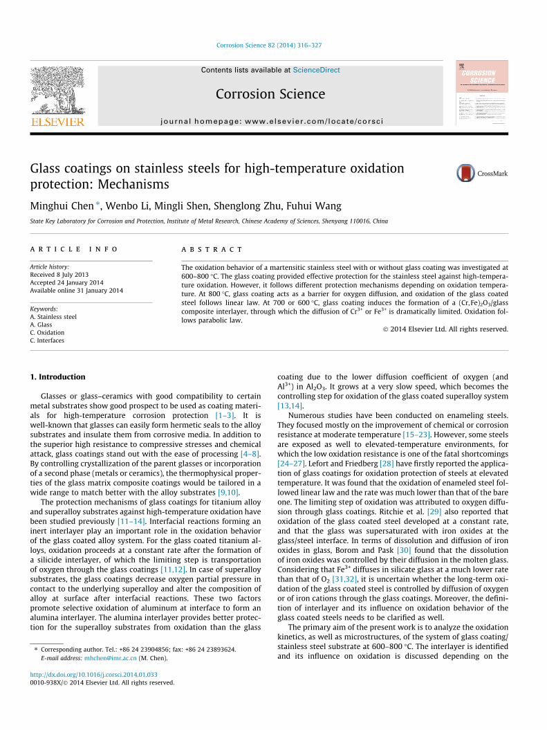
Fig. 1 shows the microstructures of the as-fired glass coatedstainless steel. Due to the low firing temperature and short sinter-ing time, the glass did not spread well on the steel surface and theremaining gases had not been released out completely. Thoughmany closed pores are found, the steel substrate is still successfullyinsulated from oxidizing atmosphere by the glass coating. From thecross-sectional view, the glass coating is about 35 lm thick, andbonds well with the steel substrate. As shown in Fig. 1B, no spall-ation of glass coating and no distinct interlayer are found at theglass/steel interface. Generally, a porous interlayer of steel oxidewill decrease the bonding strength of glass coating on steel sub-strate. XRD pattern (Fig. 2) shows that the as-fired glass coatingis still vitreous. A very broad peak near 25� is present. The onlycrystallite detected in the XRD pattern is Fe, which is attributedto the steel substrate.
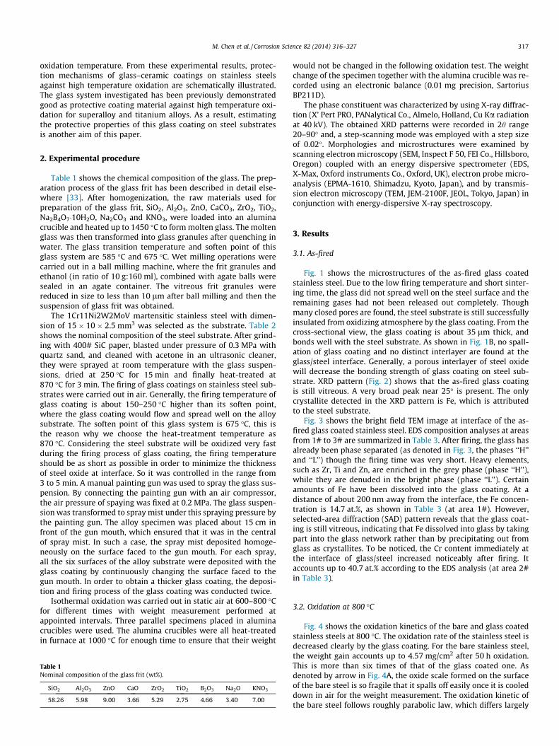
Fig. 3 shows the bright field TEM image at interface of the as-fired glass coated stainless steel. EDS composition analyses at areasfrom 1# to 3# are summarized in Table 3. After firing, the glass hasalready been phase separated (as denoted in Fig. 3, the phases ‘‘H’’and ‘‘L’’) though the firing time was very short. Heavy elements,such as Zr, Ti and Zn, are enriched in the grey phase (phase ‘‘H’’),while they are denuded in the bright phase (phase ‘‘L’’). Certainamounts of Fe have been dissolved into the glass coating. At adistance of about 200 nm away from the interface, the Fe concen-tration is 14.7 at.%, as shown in Table 3 (at area 1#). However,selected-area diffraction (SAD) pattern reveals that the glass coat-ing is still vitreous, indicating that Fe dissolved into glass by takingpart into the glass network rather than by precipitating out fromglass as crystallites. To be noticed, the Cr content immediately atthe interface of glass/steel increased noticeably after firing. Itaccounts up to 40.7 at.% according to the EDS analysis (at area 2#in Table 3).
3.2. Oxidation at 800 �C
Fig. 4 shows the oxidation kinetics of the bare and glass coatedstainless steels at 800 �C. The oxidation rate of the stainless steel isdecreased clearly by the glass coating. For the bare stainless steel,the weight gain accounts up to 4.57 mg/cm2 after 50 h oxidation.This is more than six times of that of the glass coated one. Asdenoted by arrow in Fig. 4A, the oxide scale formed on the surfaceof the bare steel is so fragile that it spalls off easily once it is cooleddown in air for the weight measurement. The oxidation kinetic ofthe bare steel follows roughly parabolic law, which differs largely
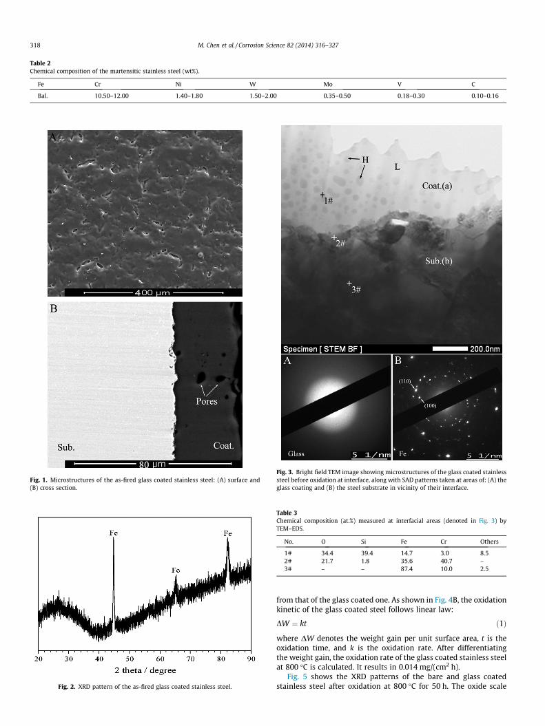
Table 2Chemical composition of the martensitic stainless steel (wt%).
Fe Cr Ni W Mo V C
Bal. 10.50–12.00 1.40–1.80 1.50–2.00 0.35–0.50 0.18–0.30 0.10–0.16
Fig. 1. Microstructures of the as-fired glass coated stainless steel: (A) surface and(B) cross section.
Fig. 2. XRD pattern of the as-fired glass coated stainless steel.
Fig. 3. Bright field TEM image showing microstructures of the glass coated stainlesssteel before oxidation at interface, along with SAD patterns taken at areas of: (A) theglass coating and (B) the steel substrate in vicinity of their interface.
Table 3Chemical composition (at.%) measured at interfacial areas (denoted in Fig. 3) byTEM–EDS.
No. O Si Fe Cr Others
1# 34.4 39.4 14.7 3.0 8.52# 21.7 1.8 35.6 40.7 –3# – – 87.4 10.0 2.5
318 M. Chen et al. / Corrosion Science 82 (2014) 316–327
from that of the glass coated one. As shown in Fig. 4B, the oxidationkinetic of the glass coated steel follows linear law:
DW ¼ kt ð1Þ
where DW denotes the weight gain per unit surface area, t is theoxidation time, and k is the oxidation rate. After differentiatingthe weight gain, the oxidation rate of the glass coated stainless steelat 800 �C is calculated. It results in 0.014 mg/(cm2 h).
Fig. 5 shows the XRD patterns of the bare and glass coatedstainless steel after oxidation at 800 �C for 50 h. The oxide scale
Fig. 4. Oxidation kinetics at 800 �C: (A) comparison between the bare stainless steeland the glass coated one and (B) enlarged kinetic curve of the glass coated steel andfitness with linear relationship.
Fig. 5. XRD patterns of the bare and glass coated stainless steels after oxidation at800 �C for 50 h (a: (Cr,Fe)2O3, b: Fe, c: ZrSiO4, d: Zn2SiO4, e: SiO2, f: Fe(SiO3)).
Fig. 6. Microstructures of the bare stainless steel after oxidation at 800 �C for 50 h:(A) surface and (B) cross section.
M. Chen et al. / Corrosion Science 82 (2014) 316–327 319
formed upon the bare steel is exclusively made up of (Cr,Fe)2O3.These mixed oxides are hardly detected in the glass coated steel.Instead small amount of Fe(SiO3) is found. The crystallizationtemperature of the parent glass system is 800 �C [34]. After 50 hoxidation, crystallites of ZrSiO4, Zn2SiO4 and SiO2 precipitate outfrom the glass coating.
Microstructures of the bare and glass coated stainless steelsafter oxidation at 800 �C are shown in Figs. 6 and 7. As shown inFig. 6A, abundant cracks nucleate and propagate in the oxide filmon the bare stainless steel, which results in spallation. From thecross-sectional view, the oxide film is divided into two scales:the outer loose one (denoted as ‘‘a’’) and the inner compact one(denoted as ‘‘b’’). The total thickness of the oxide film is about15 lm. EDS analysis indicates that the ratio Fe/Cr in the oxide filmincreases along the thickness direction, which is 84/16 in the innerscale and is 98/2 at the outer part. The region immediately beneaththe oxide scale is denuded in chromium to a depth of 15 lm (chro-mium denuded zone, CDZ). This denudation indicates loss of Cr tothe scale formed at the steel surface. The application of glass coat-ing inhibits the growth of oxide film. As shown in Fig. 7, no oxidesof iron or chromium are detected at the surface of glass coating. Atthe interface of steel/glass, a distinct interaction zone that is about3 lm thick forms. Comparing with the microstructures of theas-fired glass coated steel (Fig. 1), the glass coating becomes com-pact after oxidation at 800 �C for as long as 50 h.
Fig. 8 shows the bright field TEM images at interface of the glasscoated stainless steel after oxidation at 800 �C for 50 h. Ascompared with the as-fired one (Fig. 3), a distinct interlayer of100 nm thick formed between the glass coating and the steelsubstrate, where Cr is enriched. The glass coating is not only justphase separated but also crystallized. Particulate (the small blackdots) as well as some block-like (the arrow denoted) crystallites
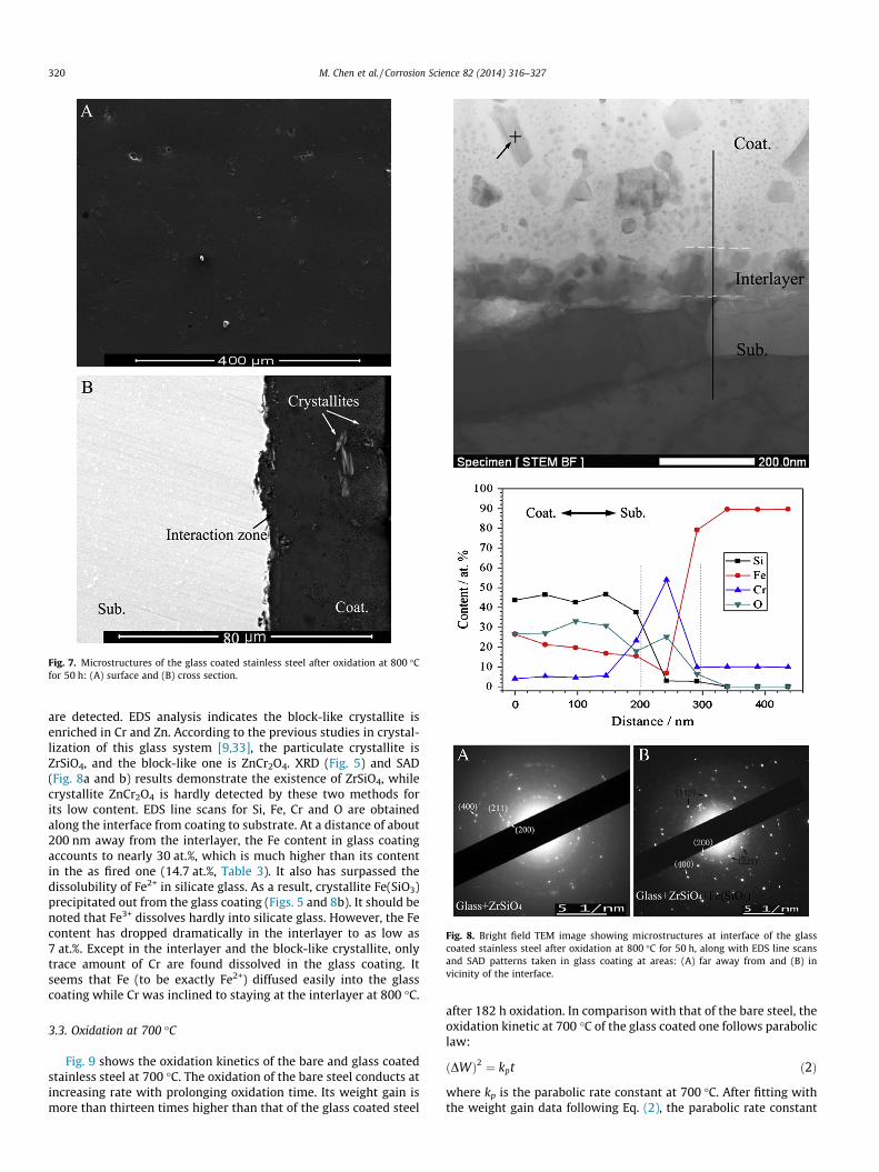
Fig. 7. Microstructures of the glass coated stainless steel after oxidation at 800 �Cfor 50 h: (A) surface and (B) cross section.
Fig. 8. Bright field TEM image showing microstructures at interface of the glasscoated stainless steel after oxidation at 800 �C for 50 h, along with EDS line scansand SAD patterns taken in glass coating at areas: (A) far away from and (B) invicinity of the interface.
320 M. Chen et al. / Corrosion Science 82 (2014) 316–327
are detected. EDS analysis indicates the block-like crystallite isenriched in Cr and Zn. According to the previous studies in crystal-lization of this glass system [9,33], the particulate crystallite isZrSiO4, and the block-like one is ZnCr2O4. XRD (Fig. 5) and SAD(Fig. 8a and b) results demonstrate the existence of ZrSiO4, whilecrystallite ZnCr2O4 is hardly detected by these two methods forits low content. EDS line scans for Si, Fe, Cr and O are obtainedalong the interface from coating to substrate. At a distance of about200 nm away from the interlayer, the Fe content in glass coatingaccounts to nearly 30 at.%, which is much higher than its contentin the as fired one (14.7 at.%, Table 3). It also has surpassed thedissolubility of Fe2+ in silicate glass. As a result, crystallite Fe(SiO3)precipitated out from the glass coating (Figs. 5 and 8b). It should benoted that Fe3+ dissolves hardly into silicate glass. However, the Fecontent has dropped dramatically in the interlayer to as low as7 at.%. Except in the interlayer and the block-like crystallite, onlytrace amount of Cr are found dissolved in the glass coating. Itseems that Fe (to be exactly Fe2+) diffused easily into the glasscoating while Cr was inclined to staying at the interlayer at 800 �C.
3.3. Oxidation at 700 �C
Fig. 9 shows the oxidation kinetics of the bare and glass coatedstainless steel at 700 �C. The oxidation of the bare steel conducts atincreasing rate with prolonging oxidation time. Its weight gain ismore than thirteen times higher than that of the glass coated steel
after 182 h oxidation. In comparison with that of the bare steel, theoxidation kinetic at 700 �C of the glass coated one follows paraboliclaw:
ðDWÞ2 ¼ kpt ð2Þ
where kp is the parabolic rate constant at 700 �C. After fitting withthe weight gain data following Eq. (2), the parabolic rate constant
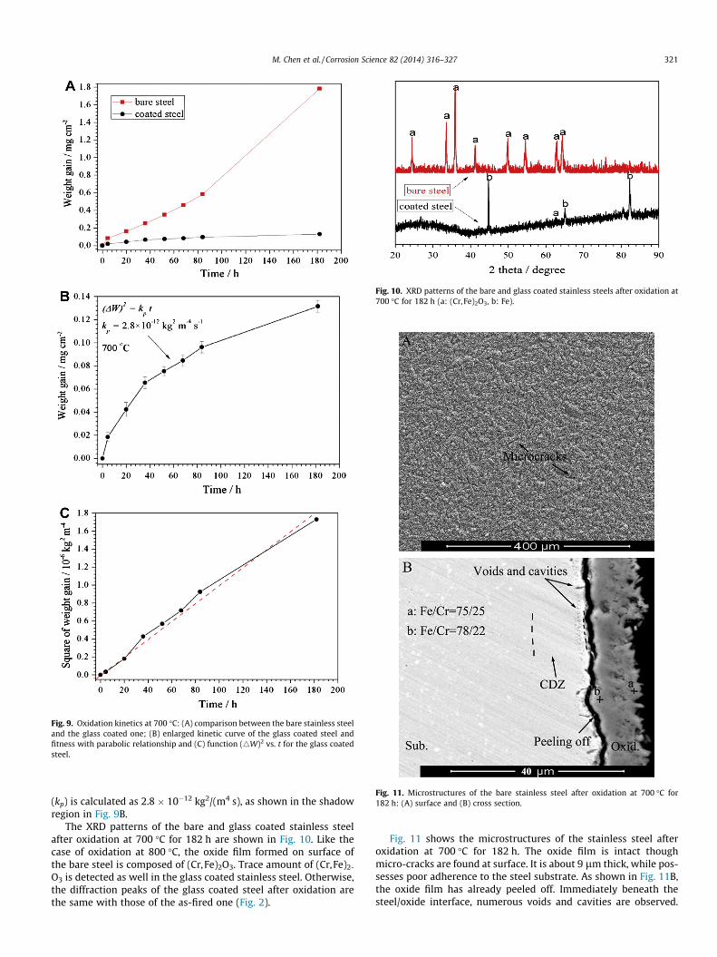
Fig. 9. Oxidation kinetics at 700 �C: (A) comparison between the bare stainless steeland the glass coated one; (B) enlarged kinetic curve of the glass coated steel andfitness with parabolic relationship and (C) function (4W)2 vs. t for the glass coatedsteel.
Fig. 10. XRD patterns of the bare and glass coated stainless steels after oxidation at700 �C for 182 h (a: (Cr,Fe)2O3, b: Fe).
Fig. 11. Microstructures of the bare stainless steel after oxidation at 700 �C for182 h: (A) surface and (B) cross section.
M. Chen et al. / Corrosion Science 82 (2014) 316–327 321
(kp) is calculated as 2.8 � 10�12 kg2/(m4 s), as shown in the shadowregion in Fig. 9B.
The XRD patterns of the bare and glass coated stainless steelafter oxidation at 700 �C for 182 h are shown in Fig. 10. Like thecase of oxidation at 800 �C, the oxide film formed on surface ofthe bare steel is composed of (Cr,Fe)2O3. Trace amount of (Cr,Fe)2-
O3 is detected as well in the glass coated stainless steel. Otherwise,the diffraction peaks of the glass coated steel after oxidation arethe same with those of the as-fired one (Fig. 2).
Fig. 11 shows the microstructures of the stainless steel afteroxidation at 700 �C for 182 h. The oxide film is intact thoughmicro-cracks are found at surface. It is about 9 lm thick, while pos-sesses poor adherence to the steel substrate. As shown in Fig. 11B,the oxide film has already peeled off. Immediately beneath thesteel/oxide interface, numerous voids and cavities are observed.
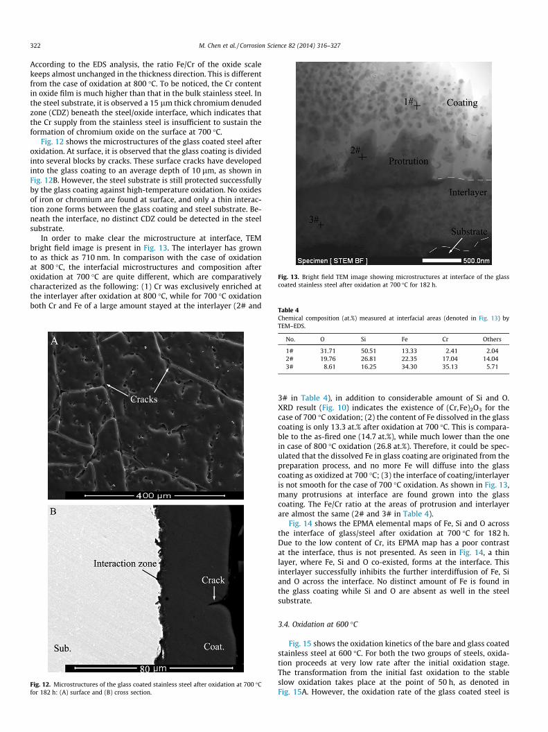
Fig. 13. Bright field TEM image showing microstructures at interface of the glasscoated stainless steel after oxidation at 700 �C for 182 h.
Table 4
322 M. Chen et al. / Corrosion Science 82 (2014) 316–327
According to the EDS analysis, the ratio Fe/Cr of the oxide scalekeeps almost unchanged in the thickness direction. This is differentfrom the case of oxidation at 800 �C. To be noticed, the Cr contentin oxide film is much higher than that in the bulk stainless steel. Inthe steel substrate, it is observed a 15 lm thick chromium denudedzone (CDZ) beneath the steel/oxide interface, which indicates thatthe Cr supply from the stainless steel is insufficient to sustain theformation of chromium oxide on the surface at 700 �C.
Fig. 12 shows the microstructures of the glass coated steel afteroxidation. At surface, it is observed that the glass coating is dividedinto several blocks by cracks. These surface cracks have developedinto the glass coating to an average depth of 10 lm, as shown inFig. 12B. However, the steel substrate is still protected successfullyby the glass coating against high-temperature oxidation. No oxidesof iron or chromium are found at surface, and only a thin interac-tion zone forms between the glass coating and steel substrate. Be-neath the interface, no distinct CDZ could be detected in the steelsubstrate.
In order to make clear the microstructure at interface, TEMbright field image is present in Fig. 13. The interlayer has grownto as thick as 710 nm. In comparison with the case of oxidationat 800 �C, the interfacial microstructures and composition afteroxidation at 700 �C are quite different, which are comparativelycharacterized as the following: (1) Cr was exclusively enriched atthe interlayer after oxidation at 800 �C, while for 700 �C oxidationboth Cr and Fe of a large amount stayed at the interlayer (2# and
Fig. 12. Microstructures of the glass coated stainless steel after oxidation at 700 �Cfor 182 h: (A) surface and (B) cross section.
Chemical composition (at.%) measured at interfacial areas (denoted in Fig. 13) byTEM–EDS.
No. O Si Fe Cr Others
1# 31.71 50.51 13.33 2.41 2.042# 19.76 26.81 22.35 17.04 14.043# 8.61 16.25 34.30 35.13 5.71
3# in Table 4), in addition to considerable amount of Si and O.XRD result (Fig. 10) indicates the existence of (Cr,Fe)2O3 for thecase of 700 �C oxidation; (2) the content of Fe dissolved in the glasscoating is only 13.3 at.% after oxidation at 700 �C. This is compara-ble to the as-fired one (14.7 at.%), while much lower than the onein case of 800 �C oxidation (26.8 at.%). Therefore, it could be spec-ulated that the dissolved Fe in glass coating are originated from thepreparation process, and no more Fe will diffuse into the glasscoating as oxidized at 700 �C; (3) the interface of coating/interlayeris not smooth for the case of 700 �C oxidation. As shown in Fig. 13,many protrusions at interface are found grown into the glasscoating. The Fe/Cr ratio at the areas of protrusion and interlayerare almost the same (2# and 3# in Table 4).
Fig. 14 shows the EPMA elemental maps of Fe, Si and O acrossthe interface of glass/steel after oxidation at 700 �C for 182 h.Due to the low content of Cr, its EPMA map has a poor contrastat the interface, thus is not presented. As seen in Fig. 14, a thinlayer, where Fe, Si and O co-existed, forms at the interface. Thisinterlayer successfully inhibits the further interdiffusion of Fe, Siand O across the interface. No distinct amount of Fe is found inthe glass coating while Si and O are absent as well in the steelsubstrate.
3.4. Oxidation at 600 �C
Fig. 15 shows the oxidation kinetics of the bare and glass coatedstainless steel at 600 �C. For both the two groups of steels, oxida-tion proceeds at very low rate after the initial oxidation stage.The transformation from the initial fast oxidation to the stableslow oxidation takes place at the point of 50 h, as denoted inFig. 15A. However, the oxidation rate of the glass coated steel is
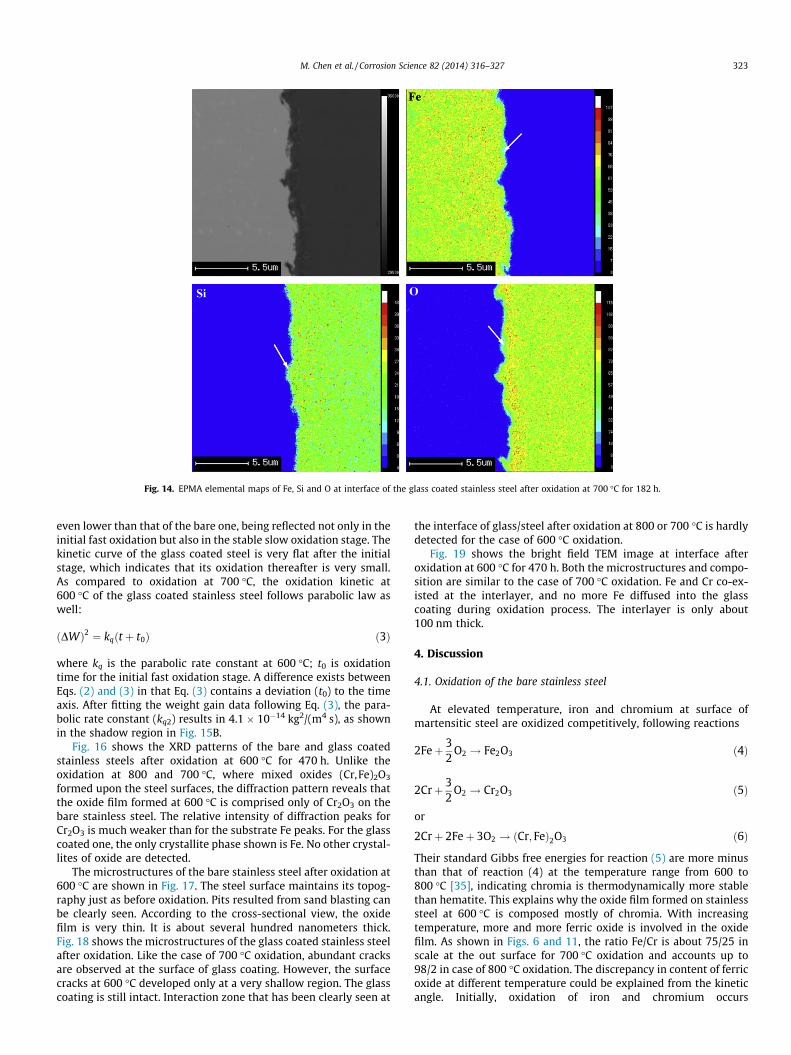
Fig. 14. EPMA elemental maps of Fe, Si and O at interface of the glass coated stainless steel after oxidation at 700 �C for 182 h.
M. Chen et al. / Corrosion Science 82 (2014) 316–327 323
even lower than that of the bare one, being reflected not only in theinitial fast oxidation but also in the stable slow oxidation stage. Thekinetic curve of the glass coated steel is very flat after the initialstage, which indicates that its oxidation thereafter is very small.As compared to oxidation at 700 �C, the oxidation kinetic at600 �C of the glass coated stainless steel follows parabolic law aswell:
ðDWÞ2 ¼ kqðt þ t0Þ ð3Þ
where kq is the parabolic rate constant at 600 �C; t0 is oxidationtime for the initial fast oxidation stage. A difference exists betweenEqs. (2) and (3) in that Eq. (3) contains a deviation (t0) to the timeaxis. After fitting the weight gain data following Eq. (3), the para-bolic rate constant (kq2) results in 4.1 � 10�14 kg2/(m4 s), as shownin the shadow region in Fig. 15B.
Fig. 16 shows the XRD patterns of the bare and glass coatedstainless steels after oxidation at 600 �C for 470 h. Unlike theoxidation at 800 and 700 �C, where mixed oxides (Cr,Fe)2O3
formed upon the steel surfaces, the diffraction pattern reveals thatthe oxide film formed at 600 �C is comprised only of Cr2O3 on thebare stainless steel. The relative intensity of diffraction peaks forCr2O3 is much weaker than for the substrate Fe peaks. For the glasscoated one, the only crystallite phase shown is Fe. No other crystal-lites of oxide are detected.
The microstructures of the bare stainless steel after oxidation at600 �C are shown in Fig. 17. The steel surface maintains its topog-raphy just as before oxidation. Pits resulted from sand blasting canbe clearly seen. According to the cross-sectional view, the oxidefilm is very thin. It is about several hundred nanometers thick.Fig. 18 shows the microstructures of the glass coated stainless steelafter oxidation. Like the case of 700 �C oxidation, abundant cracksare observed at the surface of glass coating. However, the surfacecracks at 600 �C developed only at a very shallow region. The glasscoating is still intact. Interaction zone that has been clearly seen at
the interface of glass/steel after oxidation at 800 or 700 �C is hardlydetected for the case of 600 �C oxidation.
Fig. 19 shows the bright field TEM image at interface afteroxidation at 600 �C for 470 h. Both the microstructures and compo-sition are similar to the case of 700 �C oxidation. Fe and Cr co-ex-isted at the interlayer, and no more Fe diffused into the glasscoating during oxidation process. The interlayer is only about100 nm thick.
4. Discussion
4.1. Oxidation of the bare stainless steel
At elevated temperature, iron and chromium at surface ofmartensitic steel are oxidized competitively, following reactions
2Feþ 32
O2 ! Fe2O3 ð4Þ
2Crþ 32
O2 ! Cr2O3 ð5Þ
or
2Crþ 2Feþ 3O2 ! ðCr; FeÞ2O3 ð6Þ
Their standard Gibbs free energies for reaction (5) are more minusthan that of reaction (4) at the temperature range from 600 to800 �C [35], indicating chromia is thermodynamically more stablethan hematite. This explains why the oxide film formed on stainlesssteel at 600 �C is composed mostly of chromia. With increasingtemperature, more and more ferric oxide is involved in the oxidefilm. As shown in Figs. 6 and 11, the ratio Fe/Cr is about 75/25 inscale at the out surface for 700 �C oxidation and accounts up to98/2 in case of 800 �C oxidation. The discrepancy in content of ferricoxide at different temperature could be explained from the kineticangle. Initially, oxidation of iron and chromium occurs
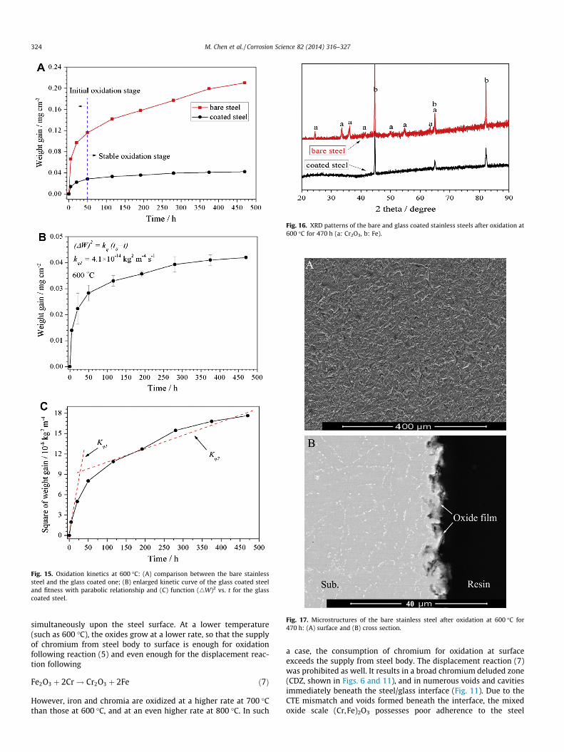
Fig. 15. Oxidation kinetics at 600 �C: (A) comparison between the bare stainlesssteel and the glass coated one; (B) enlarged kinetic curve of the glass coated steeland fitness with parabolic relationship and (C) function (4W)2 vs. t for the glasscoated steel.
Fig. 16. XRD patterns of the bare and glass coated stainless steels after oxidation at600 �C for 470 h (a: Cr2O3, b: Fe).
Fig. 17. Microstructures of the bare stainless steel after oxidation at 600 �C for470 h: (A) surface and (B) cross section.
324 M. Chen et al. / Corrosion Science 82 (2014) 316–327
simultaneously upon the steel surface. At a lower temperature(such as 600 �C), the oxides grow at a lower rate, so that the supplyof chromium from steel body to surface is enough for oxidationfollowing reaction (5) and even enough for the displacement reac-tion following
Fe2O3 þ 2Cr! Cr2O3 þ 2Fe ð7Þ
However, iron and chromia are oxidized at a higher rate at 700 �Cthan those at 600 �C, and at an even higher rate at 800 �C. In such
a case, the consumption of chromium for oxidation at surfaceexceeds the supply from steel body. The displacement reaction (7)was prohibited as well. It results in a broad chromium deluded zone(CDZ, shown in Figs. 6 and 11), and in numerous voids and cavitiesimmediately beneath the steel/glass interface (Fig. 11). Due to theCTE mismatch and voids formed beneath the interface, the mixedoxide scale (Cr,Fe)2O3 possesses poor adherence to the steel
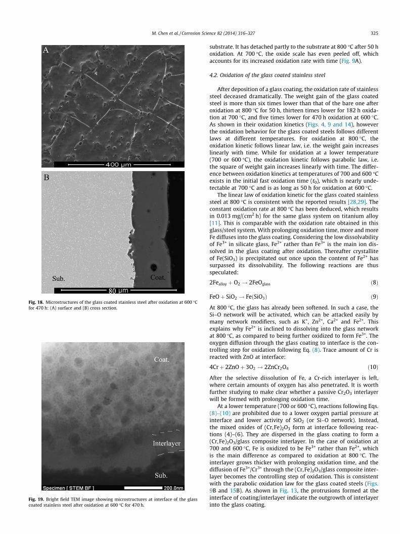
Fig. 18. Microstructures of the glass coated stainless steel after oxidation at 600 �Cfor 470 h: (A) surface and (B) cross section.
Fig. 19. Bright field TEM image showing microstructures at interface of the glasscoated stainless steel after oxidation at 600 �C for 470 h.
M. Chen et al. / Corrosion Science 82 (2014) 316–327 325
substrate. It has detached partly to the substrate at 800 �C after 50 hoxidation. At 700 �C, the oxide scale has even peeled off, whichaccounts for its increased oxidation rate with time (Fig. 9A).
4.2. Oxidation of the glass coated stainless steel
After deposition of a glass coating, the oxidation rate of stainlesssteel deceased dramatically. The weight gain of the glass coatedsteel is more than six times lower than that of the bare one afteroxidation at 800 �C for 50 h, thirteen times lower for 182 h oxida-tion at 700 �C, and five times lower for 470 h oxidation at 600 �C.As shown in their oxidation kinetics (Figs. 4, 9 and 14), howeverthe oxidation behavior for the glass coated steels follows differentlaws at different temperatures. For oxidation at 800 �C, theoxidation kinetic follows linear law, i.e. the weight gain increaseslinearly with time. While for oxidation at a lower temperature(700 or 600 �C), the oxidation kinetic follows parabolic law, i.e.the square of weight gain increases linearly with time. The differ-ence between oxidation kinetics at temperatures of 700 and 600 �Cexists in the initial fast oxidation time (t0), which is nearly unde-tectable at 700 �C and is as long as 50 h for oxidation at 600 �C.
The linear law of oxidation kinetic for the glass coated stainlesssteel at 800 �C is consistent with the reported results [28,29]. Theconstant oxidation rate at 800 �C has been deduced, which resultsin 0.013 mg/(cm2 h) for the same glass system on titanium alloy[11]. This is comparable with the oxidation rate obtained in thisglass/steel system. With prolonging oxidation time, more and moreFe diffuses into the glass coating. Considering the low dissolvabilityof Fe3+ in silicate glass, Fe2+ rather than Fe3+ is the main ion dis-solved in the glass coating after oxidation. Thereafter crystalliteof Fe(SiO3) is precipitated out once upon the content of Fe2+ hassurpassed its dissolvability. The following reactions are thusspeculated:
2Fealloy þ O2 ! 2FeOglass ð8Þ
FeOþ SiO2 ! FeðSiO3Þ ð9Þ
At 800 �C, the glass has already been softened. In such a case, theSi–O network will be activated, which can be attacked easily bymany network modifiers, such as K+, Zn2+, Ca2+ and Fe2+. Thisexplains why Fe2+ is inclined to dissolving into the glass networkat 800 �C, as compared to being further oxidized to form Fe3+. Theoxygen diffusion through the glass coating to interface is the con-trolling step for oxidation following Eq. (8). Trace amount of Cr isreacted with ZnO at interface:
4Crþ 2ZnOþ 3O2 ! 2ZnCr2O4 ð10Þ
After the selective dissolution of Fe, a Cr-rich interlayer is left,where certain amounts of oxygen has also penetrated. It is worthfurther studying to make clear whether a passive Cr2O3 interlayerwill be formed with prolonging oxidation time.
At a lower temperature (700 or 600 �C), reactions following Eqs.(8)–(10) are prohibited due to a lower oxygen partial pressure atinterface and lower activity of SiO2 (or Si–O network). Instead,the mixed oxides of (Cr,Fe)2O3 form at interface following reac-tions (4)–(6). They are dispersed in the glass coating to form a(Cr,Fe)2O3/glass composite interlayer. In the case of oxidation at700 and 600 �C, Fe is oxidized to be Fe3+ rather than Fe2+, whichis the main difference as compared to oxidation at 800 �C. Theinterlayer grows thicker with prolonging oxidation time, and thediffusion of Fe3+/Cr3+ through the (Cr,Fe)2O3/glass composite inter-layer becomes the controlling step of oxidation. This is consistentwith the parabolic oxidation law for the glass coated steels (Figs.9B and 15B). As shown in Fig. 13, the protrusions formed at theinterface of coating/interlayer indicate the outgrowth of interlayerinto the glass coating.
326 M. Chen et al. / Corrosion Science 82 (2014) 316–327
Naraparaju et al. [36] reported that the parabolic rate constantof a martensitic steel containing 12 wt% Cr at 700 �C was7.89 � 10�10 kg2 cm�4 s�1, for which the oxide scale was composedof a Fe2O3 + Fe3O4 outer layer and a dense Fe3O4 + FeCr2O4 innerlayer. The oxidation of Fe contributes mostly to the weight gain.In comparison, the parabolic rate constant for the investigatedglass/steel system at 700 �C is two orders of magnitude lower(2.8 � 10�12 kg2 cm�4 s�1). This means that the diffusion of Fethrough the (Cr,Fe)2O3/glass composite interlayer is much lowerthan through a dense FeCr2O4 layer at 700 �C. This is agreed tothe very low diffusivities of Fe3+ and Cr3+ in silicate glasses. In fact,the composite interlayer grows at an even lower rate than thegrowth of Cr2O3 film on the steel substrate at 600 �C (Fig. 15A).Due to the lower rate of oxides growing at 600 �C than at 700 �C,there should be a longer time for the formation of an intact(Cr,Fe)2O3/glass composite interlayer for 600 �C oxidation. Priorto the formation of an intact composite interlayer, oxidationkinetic of the glass coated steel at 600 �C might deviate from par-abolic law, as it has performed during the initial 50 h oxidation.
In the view of surface morphology, cracks form at the surface ofglass coatings in cases of heat-treatment at temperatures of 600and 700 �C, while are absent for firing at 800 �C. After surpass theglass transition temperature (585 �C), the thermal expansion coef-ficient of glass increases sharply, which is higher than the steelsubstrate. As a result, tensile stress forms in the glass coating asthe glass coated steel is fired at 600 and 700 �C. The high tensilestress accounts for the formation of surface cracks. However, many
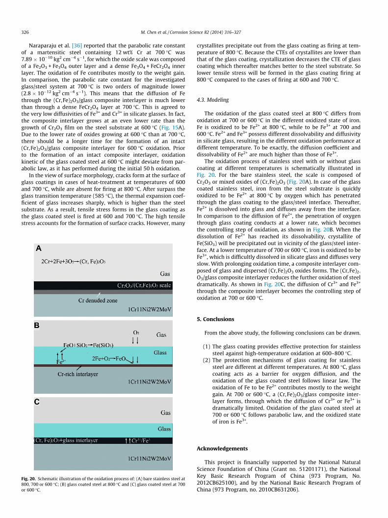
Fig. 20. Schematic illustration of the oxidation process of: (A) bare stainless steel at800, 700 or 600 �C; (B) glass coated steel at 800 �C and (C) glass coated steel at 700or 600 �C.
crystallites precipitate out from the glass coating as firing at tem-perature of 800 �C. Because the CTEs of crystallites are lower thanthat of the glass coating, crystallization decreases the CTE of glasscoating which thereafter matches better to the steel substrate. Solower tensile stress will be formed in the glass coating firing at800 �C compared to the cases of firing at 600 and 700 �C.
4.3. Modeling
The oxidation of the glass coated steel at 800 �C differs fromoxidation at 700 or 600 �C in the different oxidized state of iron.Fe is oxidized to be Fe2+ at 800 �C, while to be Fe3+ at 700 and600 �C. Fe2+ and Fe3+ possess different dissolvability and diffusivityin silicate glass, resulting in the different oxidation performance atdifferent temperature. To be exactly, the diffusion coefficient anddissolvability of Fe2+ are much higher than those of Fe3+.
The oxidation process of stainless steel with or without glasscoating at different temperatures is schematically illustrated inFig. 20. For the bare stainless steel, the scale is composed ofCr2O3 or mixed oxides of (Cr,Fe)2O3 (Fig. 20A). In case of the glasscoated stainless steel, iron from the steel substrate is quicklyoxidized to be Fe2+ at 800 �C by oxygen which has penetratedthrough the glass coating to the glass/steel interface. Thereafter,Fe2+ is dissolved into glass and diffuses away from the interface.In comparison to the diffusion of Fe2+, the penetration of oxygenthrough glass coating conducts at a lower rate, which becomesthe controlling step of oxidation, as shown in Fig. 20B. When thedissolution of Fe2+ has reached its dissolvability, crystallite ofFe(SiO3) will be precipitated out in vicinity of the glass/steel inter-face. At a lower temperature of 700 or 600 �C, iron is oxidized to beFe3+, which is difficultly dissolved in silicate glass and diffuses veryslow. With prolonging oxidation time, a composite interlayer com-posed of glass and dispersed (Cr,Fe)2O3 oxides forms. The (Cr,Fe)2-
O3/glass composite interlayer reduces the further oxidation of steeldramatically. As shown in Fig. 20C, the diffusion of Cr3+ and Fe3+
through the composite interlayer becomes the controlling step ofoxidation at 700 or 600 �C.
5. Conclusions
From the above study, the following conclusions can be drawn.
(1) The glass coating provides effective protection for stainlesssteel against high-temperature oxidation at 600–800 �C.
(2) The protection mechanisms of glass coating for stainlesssteel are different at different temperatures. At 800 �C, glasscoating acts as a barrier for oxygen diffusion, and theoxidation of the glass coated steel follows linear law. Theoxidation of Fe to be Fe2+ contributes mostly to the weightgain. At 700 or 600 �C, a (Cr,Fe)2O3/glass composite inter-layer forms, through which the diffusion of Cr3+ or Fe3+ isdramatically limited. Oxidation of the glass coated steel at700 or 600 �C follows parabolic law, and the oxidized stateof iron is Fe3+.
Acknowledgements
This project is financially supported by the National NaturalScience Foundation of China (Grant no. 51201171), the NationalKey Basic Research Program of China (973 Program, No.2012CB625100), and by the National Basic Research Program ofChina (973 Program, no. 2010CB631206).
M. Chen et al. / Corrosion Science 82 (2014) 316–327 327
References
[1] I.W. Donald, P.M. Mallinson, B.L. Metcalfe, L.A. Gerrard, J.A. Fernie, Recentdevelopments in the preparation, characterization and applications of glass-and glass-ceramic-to-metal seals and coatings, J. Mater. Sci. 48 (2011) 1975–2000.
[2] Y. Xiong, S. Zhu, F. Wang, Synergistic corrosion behavior of coated Ti60 alloyswith NaCl deposit in moist air at elevated temperature, Corros. Sci. 50 (2008)15–22.
[3] S. Datta, S. Das, A new high temperature resistant glass-ceramic coating for gasturbine engine components, Bull. Mater. Sci. 28 (2005) 689–696.
[4] A. Conde, J.J. de Damborenea, Electrochemical impedance spectroscopy forstudying the degradation of enamel coatings, Corros. Sci. 44 (2002) 1555–1567.
[5] T. Moskalewicz, F. Smeacetto, G. Cempura, L.C. Ajitdoss, M. Salvo, A. Czyrska-Filemonowicz, Microstructure and properties characterization of the doublelayered glass-ceramic coating on near-a titanium alloy, Surf. Coat. Technol.204 (2010) 3509–3516.
[6] T.S. Chern, H.L. Tsai, Wetting and sealing of interface between 7056 glass andkovar alloy, Mater. Chem. Phys. 104 (2007) 472–478.
[7] F. Tang, G. Chen, R.K. Brow, J.S. Volz, M.L. Koenigstein, Corrosion resistance andmechanism of steel rebar coated with three types of enamel, Corros. Sci. 59(2012) 157–168.
[8] A. Pazo, E. Saiz, A.P. Tomsia, Silicate glass coatings on Ti-based implants, ActaMater. 46 (1998) 2551–2558.
[9] M. Chen, M. Shen, S. Zhu, F. Wang, Y. Niu, Preparation and thermal shockbehavior at 1000 �C of a glass-alumina-NiCrAlY tri-composite coating on K38Gsuperalloy, Surf. Coat. Technol. 206 (2012) 2566–2571.
[10] M. Dietrich, V. Verlotski, R. Vassen, D. Stoever, Metal-glass based compositesfor novel TBC-systems, Mater. Sci. Eng. Technol. 32 (2001) 669–672.
[11] M. Chen, W. Li, M. Shen, S. Zhu, F. Wang, Glass-ceramic coatings on titaniumalloys for high temperature oxidation protection: oxidation kinetics andmicrostructure, Corros. Sci. 74 (2013) 178–186.
[12] W. Li, S. Zhu, C. Wang, M. Chen, M. Shen, F. Wang, SiO2–Al2O3–glass compositecoating on Ti–6Al–4V alloy: oxidation and interfacial reaction behavior,Corros. Sci. 74 (2013) 367–378.
[13] M. Chen, M. Shen, S. Zhu, F. Wang, X. Wang, Effect of sand blasting and glassmatrix composite coating on oxidation resistance of a nickel-based superalloyat 1000 �C, Corros. Sci. 73 (2013) 331–341.
[14] M. Chen, M. Shen, S. Zhu, F. Wang, Comparative study of interfacial reactionbetween superalloy substrate and glass coating with and without aluminaparticles incorporation, Appl. Surf. Sci. 271 (2013) 228–233.
[15] F. Tang, X. Cheng, G. Chen, R.K. Brow, J.S. Volz, M.L. Koenigstein,Electrochemical behavior of enamel-coated carbon steel in simulatedconcrete pore water solution with various chloride concentrations,Electrochim. Acta 92 (2013) 36–46.
[16] X. Yang, A. Jha, R. Brydson, R.C. Cochrane, The effects of a nickel oxide precoaton the gas bubble structures and fish-scaling resistance in vitreous enamels,Mater. Sci. Eng. A 366 (2004) 254–261.
[17] X. Yang, A. Jha, R. Brydson, R.C. Cochrane, An analysis of the microstructureand interfacial chemistry of steel–enamel interface, Thin Solid Films 443(2003) 33–45.
[18] D. Wang, Effect of crystallization on the property of hard enamel coating onsteel substrate, Appl. Surf. Sci. 255 (2009) 4640–4645.
[19] F.S. Shieu, M.J. Deng, K.C. Lin, J.C. Wong, J.Y. Wu, Effect of surfacepretreatments on the adherence of porcelain enamel to a type 316L stainlesssteel, J. Mater. Sci. 34 (1999) 5265–5272.
[20] A. Majumdar, S. Jana, Glass and glass-ceramic coatings, versatile materials forindustrial and engineering applications, Bull. Mater. Sci. 24 (2001) 69–77.
[21] L. Samiee, H. Sarpoolaky, A. Mirhabibi, Microstructure and adherence of cobaltcontaining and cobalt free enamels to low carbon steel, Mater. Sci. Eng. A 458(2007) 88–95.
[22] H.H. Liu, Y. Shueh, F.S. Yang, P. Shen, Microstructure of the enamel–steelinterface: cross-sectional TEM and metallographic studies, Mater. Sci. Eng. A149 (1992) 217–224.
[23] M.P. Borom, J.A. Pask, Role of ‘‘adherence oxides’’ in the development ofchemical bonding at glass–metal interfaces, J. Am. Ceram. Soc. 49 (1966) 1–6.
[24] F. Riffard, H. Buscail, E. Caudron, R. Cueff, C. Issartel, S. Perrier, Yttrium sol–gelcoating effects on the cyclic oxidation behaviour of 304 stainless steel, Corros.Sci. 45 (2003) 2867–2880.
[25] C. Ostwald, H.J. Grabke, Initial oxidation and chromium diffusion. I. Effects ofsurface working on 9–20% Cr steels, Corros. Sci. 46 (2004) 1113–1127.
[26] M.A.E. Jepson, R.L. Higginson, The influence of microstructure on the oxidationof duplex stainless steels in simulated propane combustion products at1000 �C, Corros. Sci. 51 (2009) 588–594.
[27] A. Talekar, D. Chandra, R. Chellappa, J. Daemen, N. Tamura, M. Kunz, Oxidationkinetics of high strength low alloy steels at elevated temperatures, Corros. Sci.50 (2008). pp. 2804–0815.
[28] H.G. Lefort, A.L. Friedberg, Quantitative high-temperature oxidation ofporcelain enameled iron, J. Am. Ceram. Soc. 41 (1958) 216–226.
[29] D. Ritchie, H.A. Schaeffer, D. White, The presence of an iron oxide layer at theenamel/steel interface in one-coat porcelain enamelling, J. Mater. Sci. 18(1983) 599–604.
[30] M.P. Borom, J.A. Pask, Kinetics of dissolution and diffusion of the oxides of ironin sodium disilicate glass, J. Am. Ceram. Soc. 51 (1968) 490–498.
[31] S. Gerlach, O. Clauben, C. Rüssel, Self-diffusion of iron in alkali–magnesia–silicaglass melts, J. Non-Cryst. Solids 226 (1998) 11–18.
[32] E.W. Sucov, Diffusion of oxygen in vitreous silica, J. Am. Ceram. Soc. 46 (1963)14–20.
[33] M. Chen, S. Zhu, F. Wang, Crystallization behavior of SiO2–Al2O3–ZnO–CaOglass system at 1123–1273 K, J. Am. Ceram. Soc. 93 (2010) 3230–3235.
[34] M. Chen, S. Zhu, M. Shen, F. Wang, Y. Niu, Effect of NiCrAlY platelets inclusionon the mechanical and thermal shock properties of glass matrix composites,Mater. Sci. Eng. A 528 (2011) 1360–1366.
[35] Y. Liang, Y. Che, Handbook of Thermodynamic Data in Inorganic, NortheasternUniversity Press, Shenyang, China, 1993.
[36] R. Naraparaju, H.-J. Christ, F.U. Renner, A. Kostka, Effect of shot-peening on theoxidation behaviour of boiler steels, Oxid. Met. 76 (2011) 233–245.


![Porous PEO coatings on titanium, obtained under DC regime ... · Keywords: Plasma Electrolytic Oxidation (PEO); Micro Arc Oxidation (MAO); ... Standard electropolishing (EP) [1-5],](https://img.pdfslide.net/doc/110x75/5afa7c4d7f8b9ad2208f534f/porous-peo-coatings-on-titanium-obtained-under-dc-regime-plasma-electrolytic.jpg)