Embed Size (px)
Citation preview
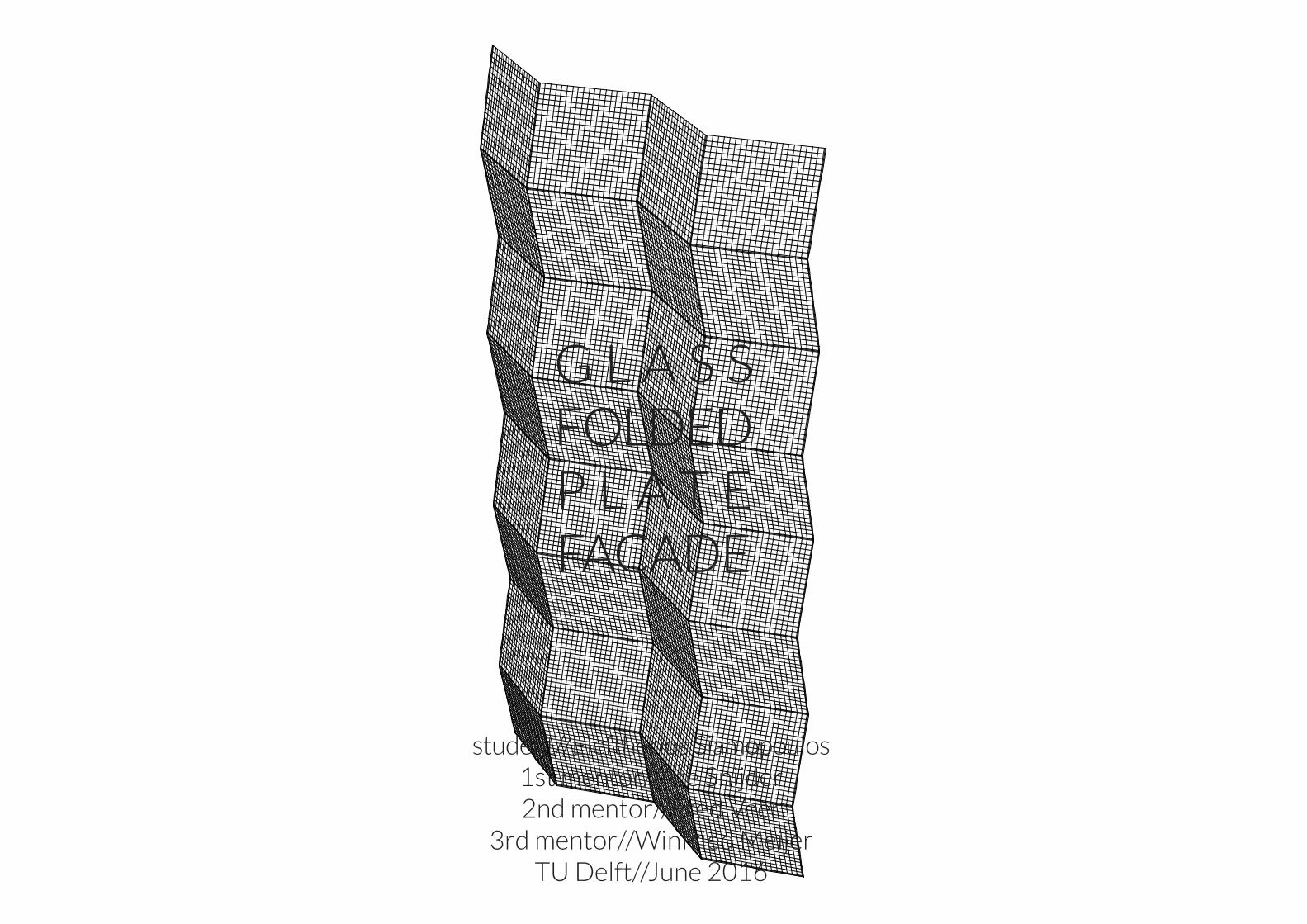
G L A S S FOLDEDP L A T E FACADE
student//Eleftherios Siamopoulos1st mentor//Ate Snijder2nd mentor//Fred Veer
3rd mentor//Winfried MeijerTU Delft//June 2016
//INTRODUCTION
//RESEARCH OBJECTIVES
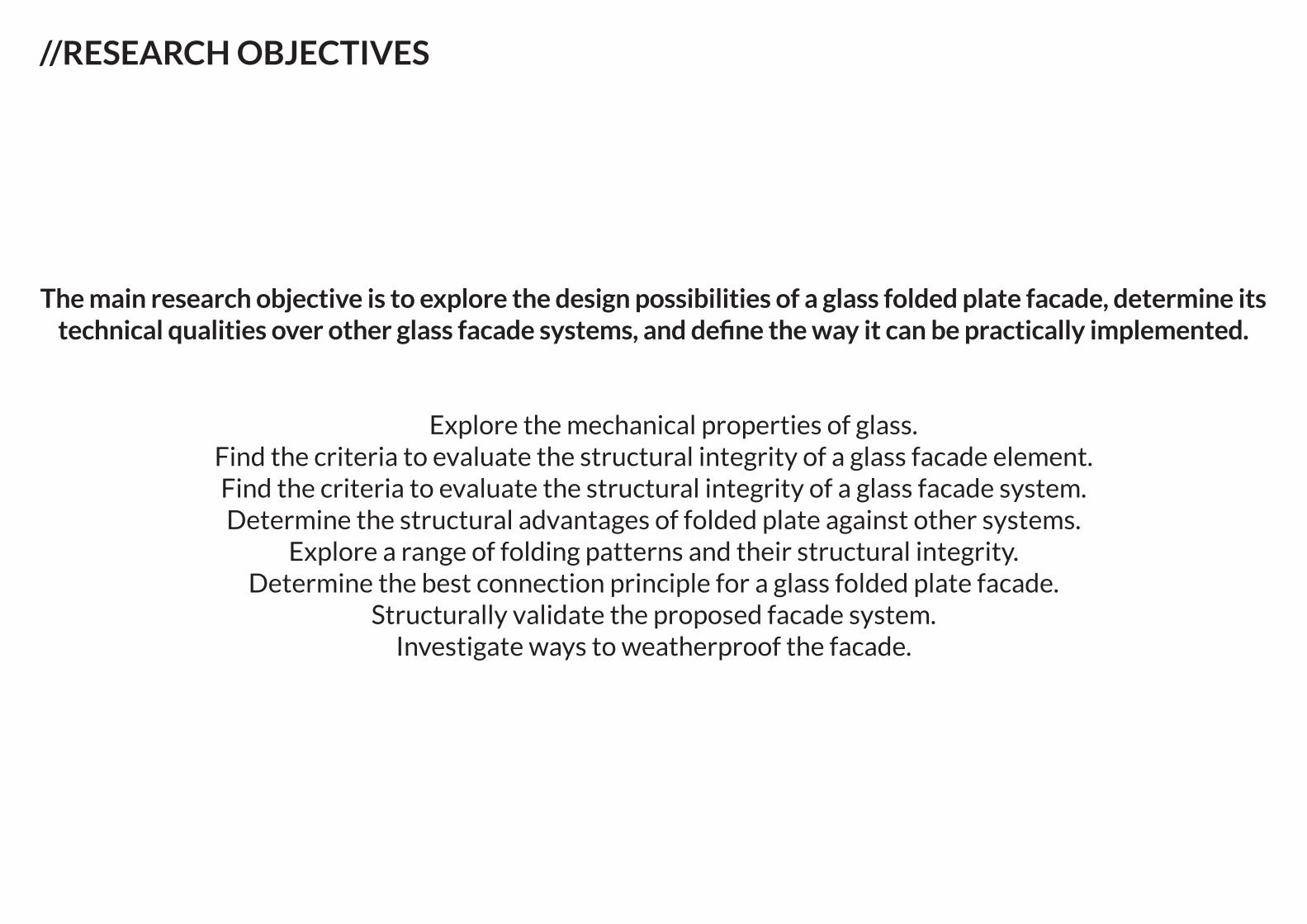
The main research objective is to explore the design possibilities of a glass folded plate facade, determine its technical qualities over other glass facade systems, and define the way it can be practically implemented.
Explore the mechanical properties of glass.Find the criteria to evaluate the structural integrity of a glass facade element.Find the criteria to evaluate the structural integrity of a glass facade system.Determine the structural advantages of folded plate against other systems.
Explore a range of folding patterns and their structural integrity.Determine the best connection principle for a glass folded plate facade.
Structurally validate the proposed facade system.Investigate ways to weatherproof the facade.
//RESEARCH STRUCTURE
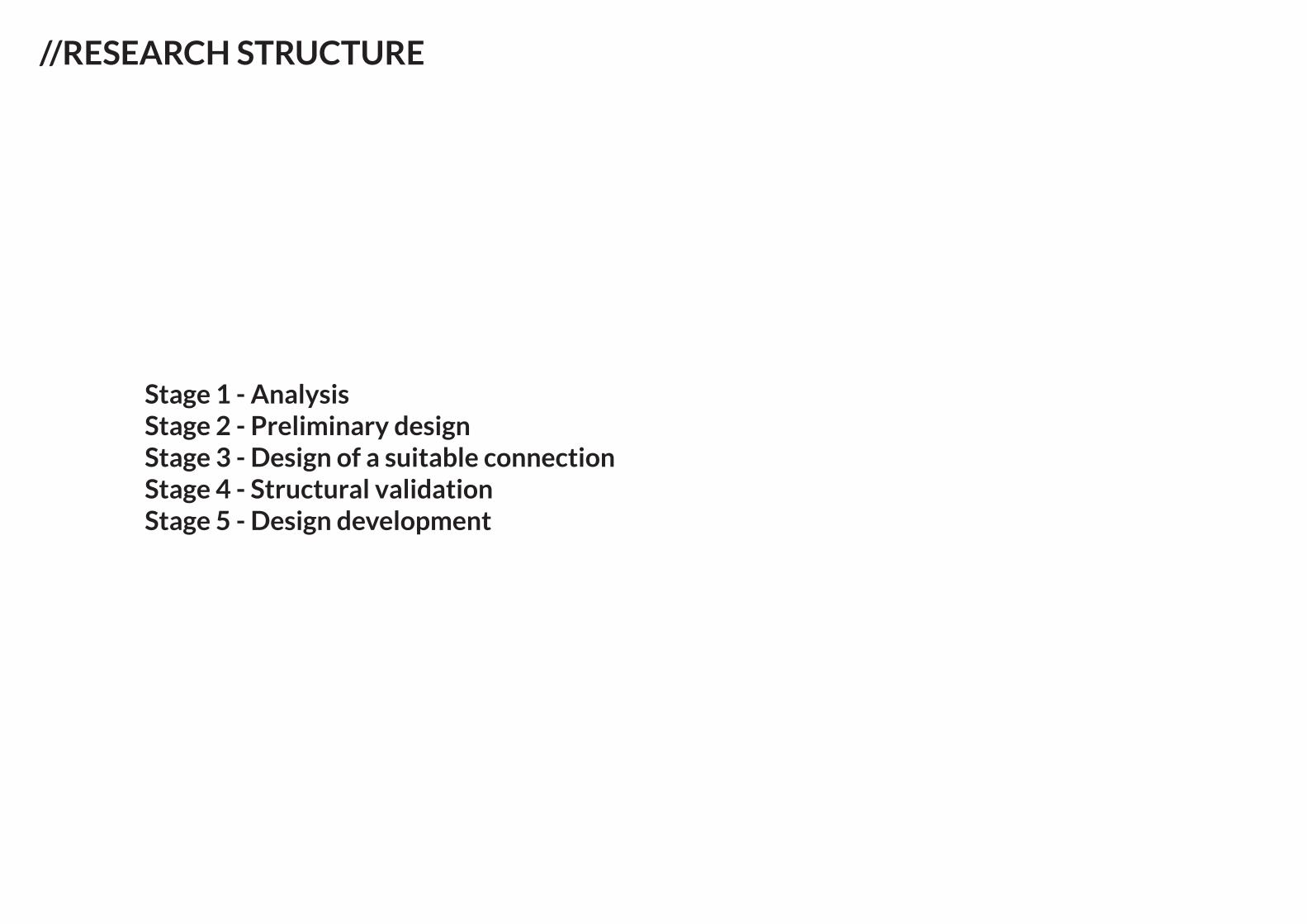
Stage 1 - AnalysisStage 2 - Preliminary designStage 3 - Design of a suitable connectionStage 4 - Structural validationStage 5 - Design development
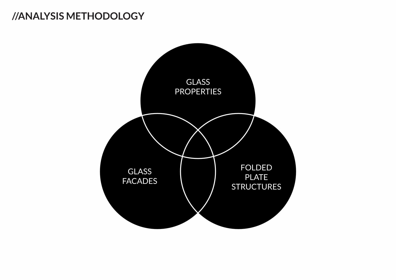
GLASSPROPERTIES
FOLDEDPLATE
STRUCTURES
GLASSFACADES
//ANALYSIS METHODOLOGY
//GLASS PROPERTIES
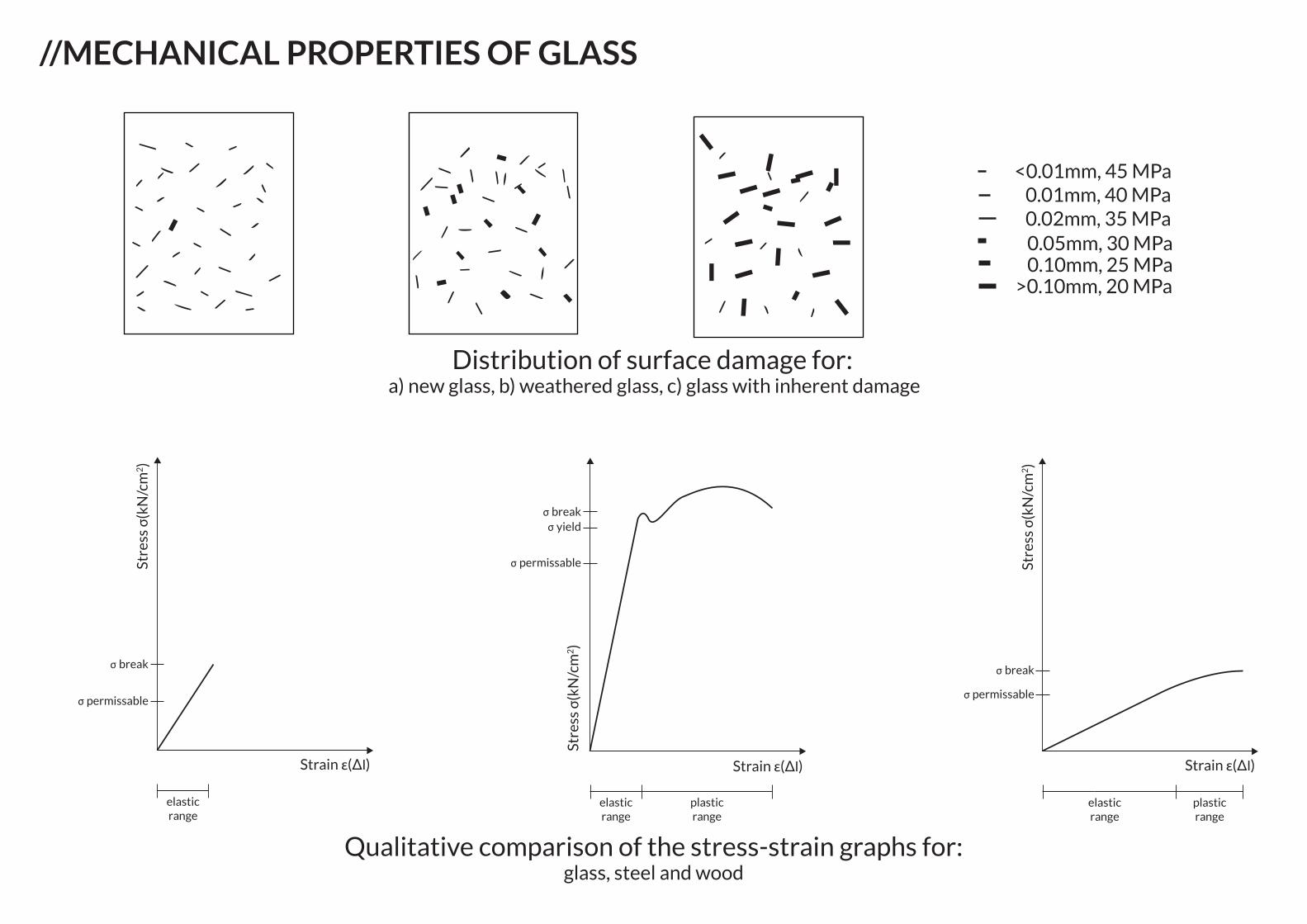
//MECHANICAL PROPERTIES OF GLASS
elastic range
plastic range
elastic range
plastic range
elastic range
<0.01mm, 45 MPa0.01mm, 40 MPa0.02mm, 35 MPa0.05mm, 30 MPa0.10mm, 25 MPa
>0.10mm, 20 MPa
Distribution of surface damage for: a) new glass, b) weathered glass, c) glass with inherent damage
Qualitative comparison of the stress-strain graphs for: glass, steel and wood
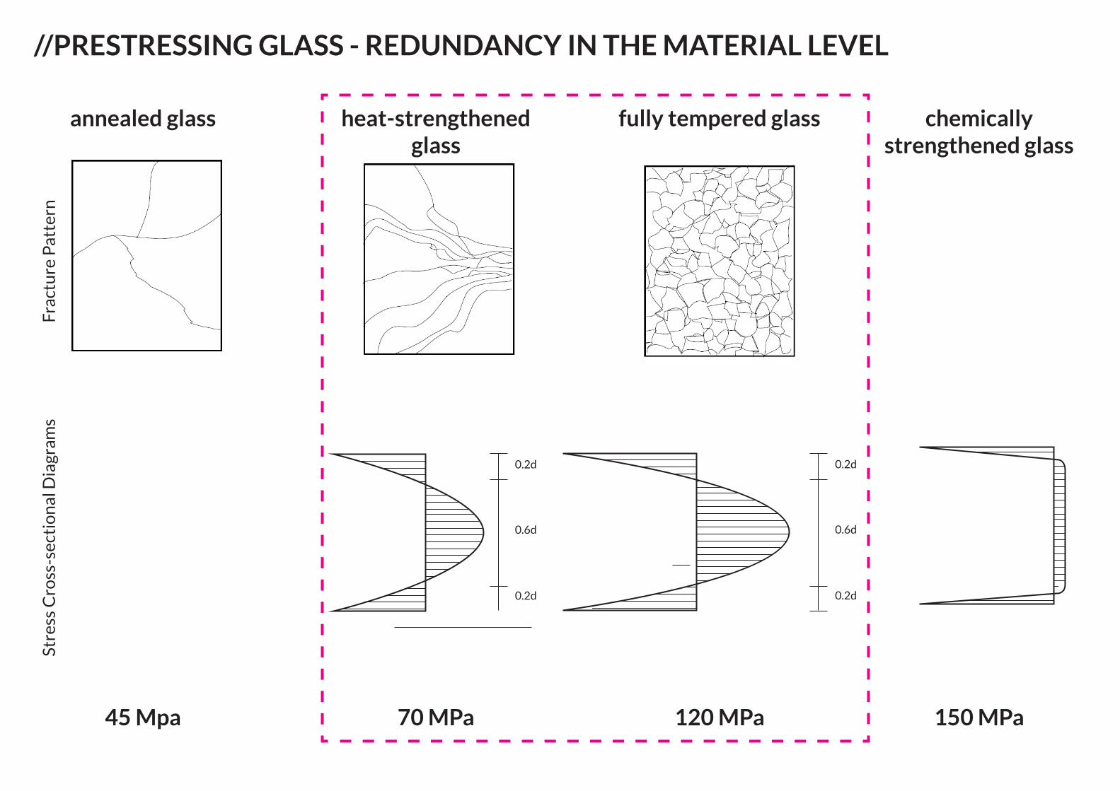
//PRESTRESSING GLASS - REDUNDANCY IN THE MATERIAL LEVEL
0.2d
0.2d
0.6d
0.2d
0.2d
0.6d
annealed glass
45 Mpa
heat-strengthened glass
70 MPa
Stre
ss C
ross
-sec
tio
nal
Dia
gram
s Fr
actu
re P
atte
rn
fully tempered glass
120 MPa
chemically strengthened glass
150 MPa
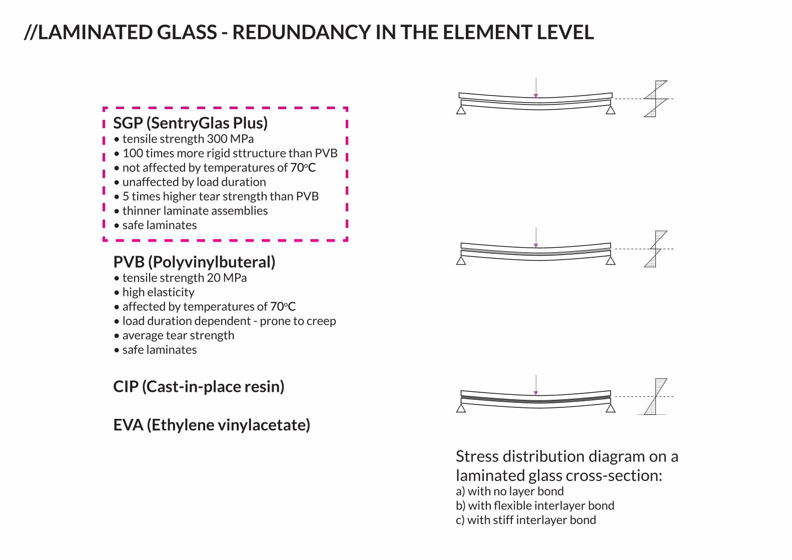
//LAMINATED GLASS - REDUNDANCY IN THE ELEMENT LEVEL
SGP (SentryGlas Plus)• tensile strength 300 MPa• 100 times more rigid sttructure than PVB• not affected by temperatures of 70oC• unaffected by load duration• 5 times higher tear strength than PVB• thinner laminate assemblies• safe laminates
PVB (Polyvinylbuteral)• tensile strength 20 MPa• high elasticity• affected by temperatures of 70oC• load duration dependent - prone to creep• average tear strength• safe laminates
CIP (Cast-in-place resin)
EVA (Ethylene vinylacetate)
Stress distribution diagram on a laminated glass cross-section:a) with no layer bondb) with flexible interlayer bondc) with stiff interlayer bond
//GLASS FACADES
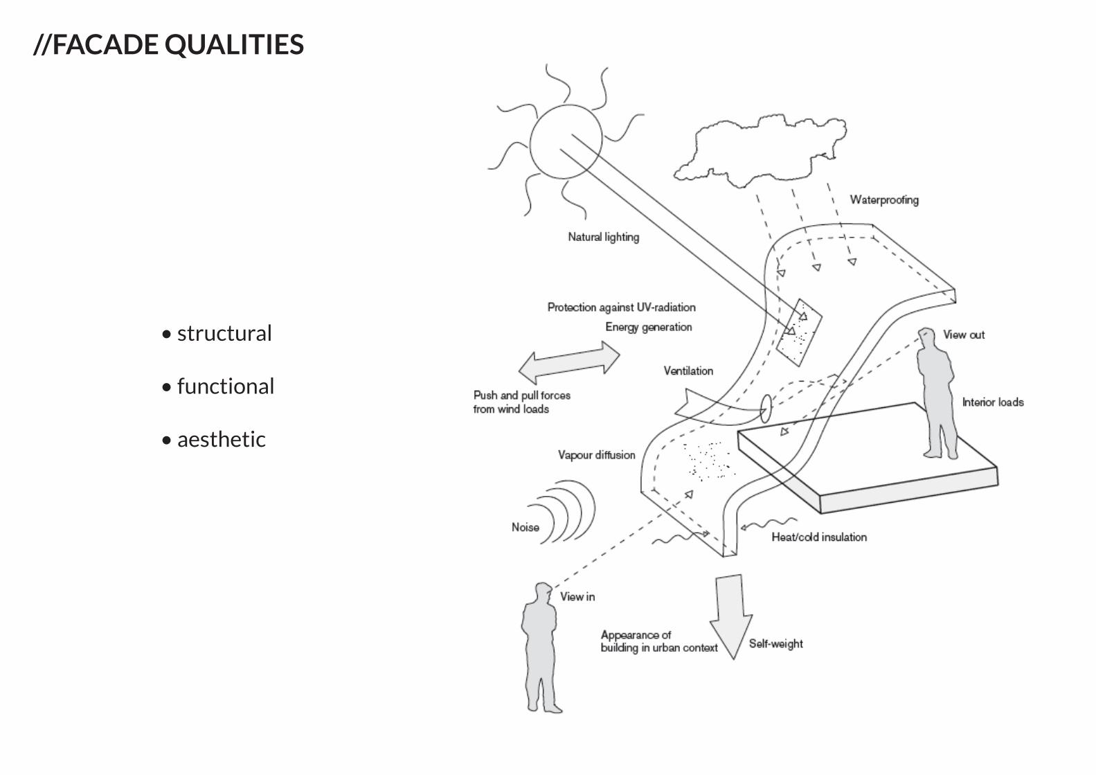
//FACADE QUALITIES
• structural
• functional
• aesthetic
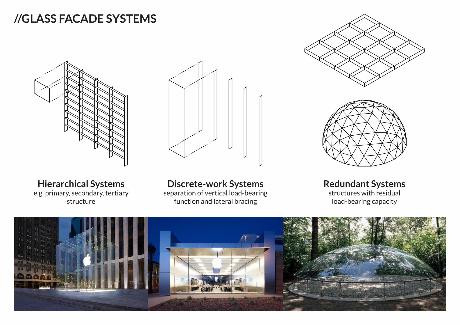
//GLASS FACADE SYSTEMS
Hierarchical Systems e.g. primary, secondary, tertiary
structure
Discrete-work Systemsseparation of vertical load-bearing
function and lateral bracing
Redundant Systemsstructures with residual
load-bearing capacity
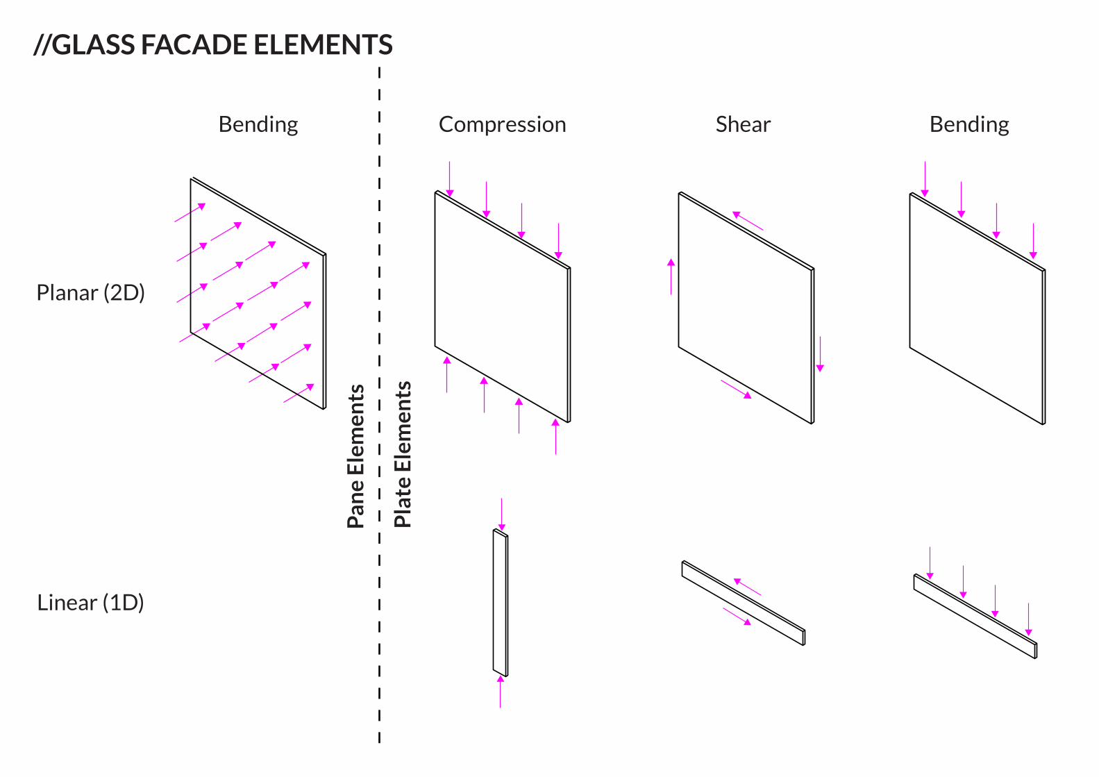
//GLASS FACADE ELEMENTS
Planar (2D)
Linear (1D)
BendingShearCompressionBending
Pla
te E
lem
ents
Pan
e E
lem
ents
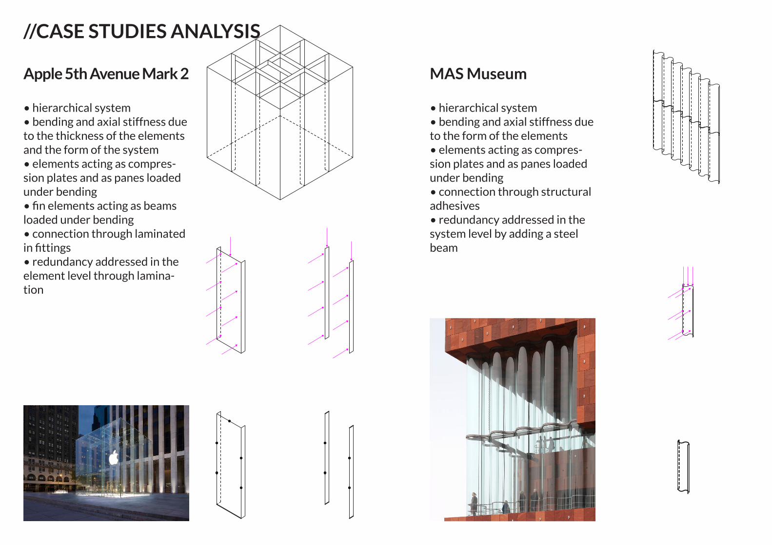
//CASE STUDIES ANALYSIS
Apple 5th Avenue Mark 2
• hierarchical system• bending and axial stiffness due to the thickness of the elements and the form of the system• elements acting as compres-sion plates and as panes loaded under bending • fin elements acting as beams loaded under bending• connection through laminated in fittings• redundancy addressed in the element level through lamina-tion
MAS Museum
• hierarchical system• bending and axial stiffness due to the form of the elements• elements acting as compres-sion plates and as panes loaded under bending • connection through structural adhesives• redundancy addressed in the system level by adding a steel beam
//FOLDED PLATE STRUCTURES
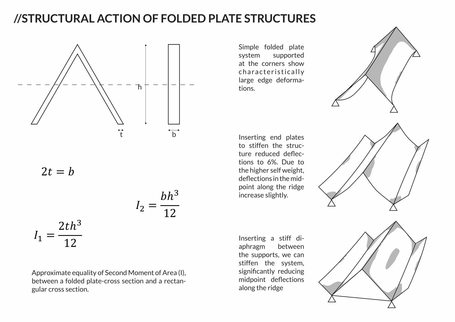
//STRUCTURAL ACTION OF FOLDED PLATE STRUCTURES
h
t b
� = ���8
� = ���
�� = �ℎ�12
2� = �
�� = 2�ℎ�12
� = ���8
� = ���
�� = �ℎ�12
2� = �
�� = 2�ℎ�12
Approximate equality of Second Moment of Area (I), between a folded plate-cross section and a rectan-gular cross section.
Simple folded plate system supported at the corners show c h a r a c t e r i s t i c a l l y large edge deforma-tions.
Inserting end plates to stiffen the struc-ture reduced deflec-tions to 6%. Due to the higher self weight, deflections in the mid-point along the ridge increase slightly.
Inserting a stiff di-aphragm between the supports, we can stiffen the system, significantly reducing midpoint deflections along the ridge
RR
R R
RR
Q
RR
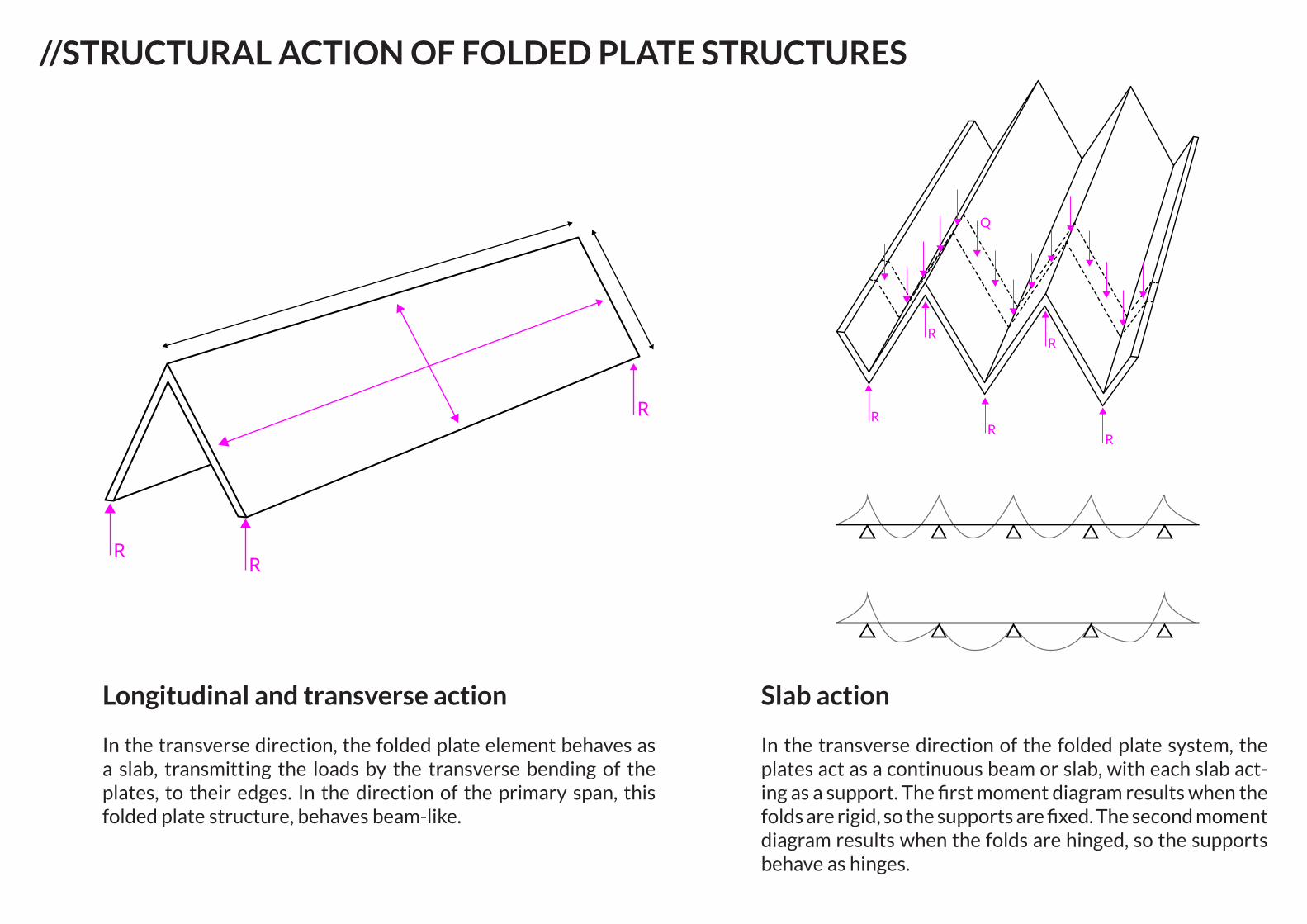
//STRUCTURAL ACTION OF FOLDED PLATE STRUCTURES
Longitudinal and transverse action
In the transverse direction, the folded plate element behaves as a slab, transmitting the loads by the transverse bending of the plates, to their edges. In the direction of the primary span, this folded plate structure, behaves beam-like.
Slab action
In the transverse direction of the folded plate system, the plates act as a continuous beam or slab, with each slab act-ing as a support. The first moment diagram results when the folds are rigid, so the supports are fixed. The second moment diagram results when the folds are hinged, so the supports behave as hinges.
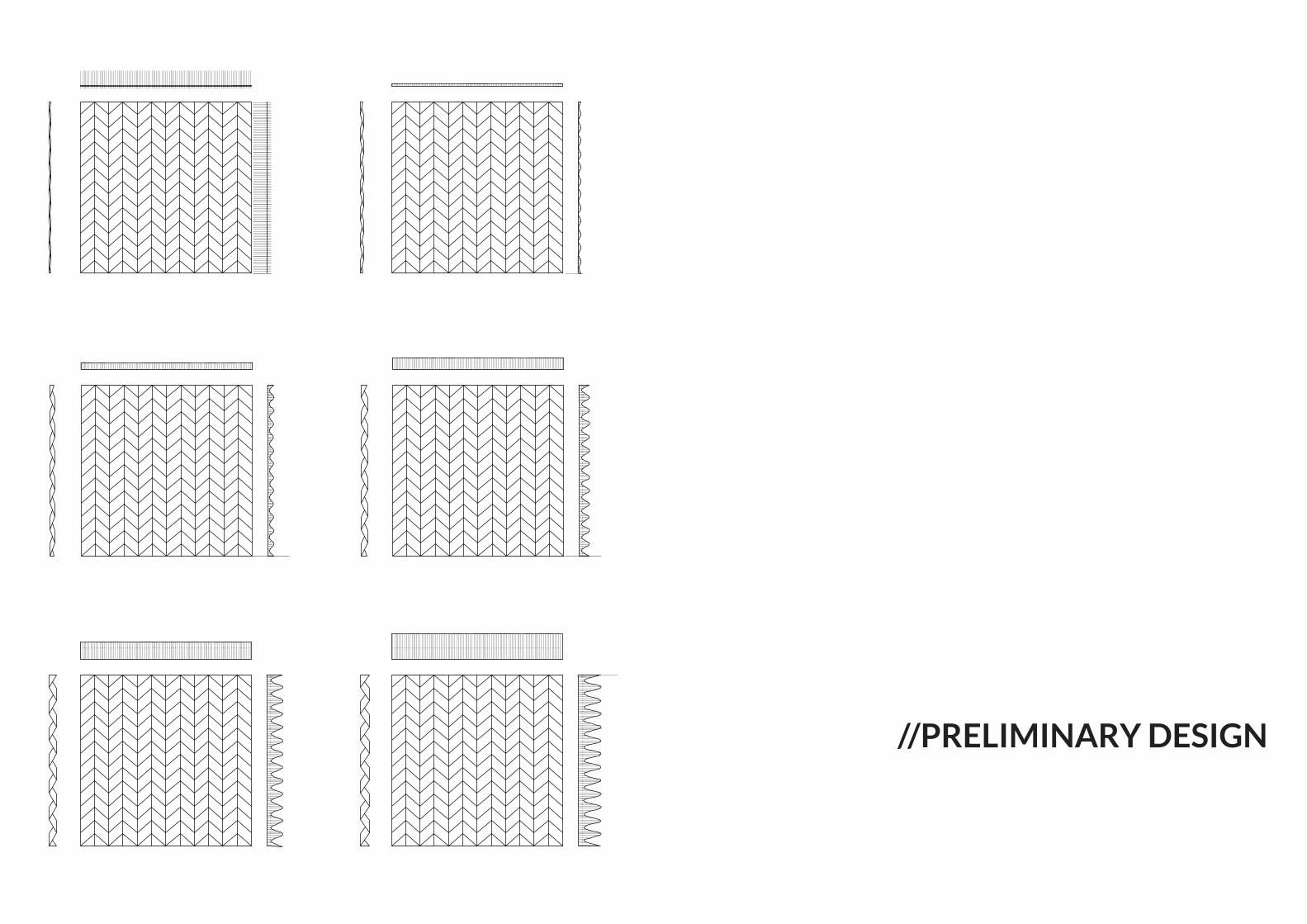
//PRELIMINARY DESIGN
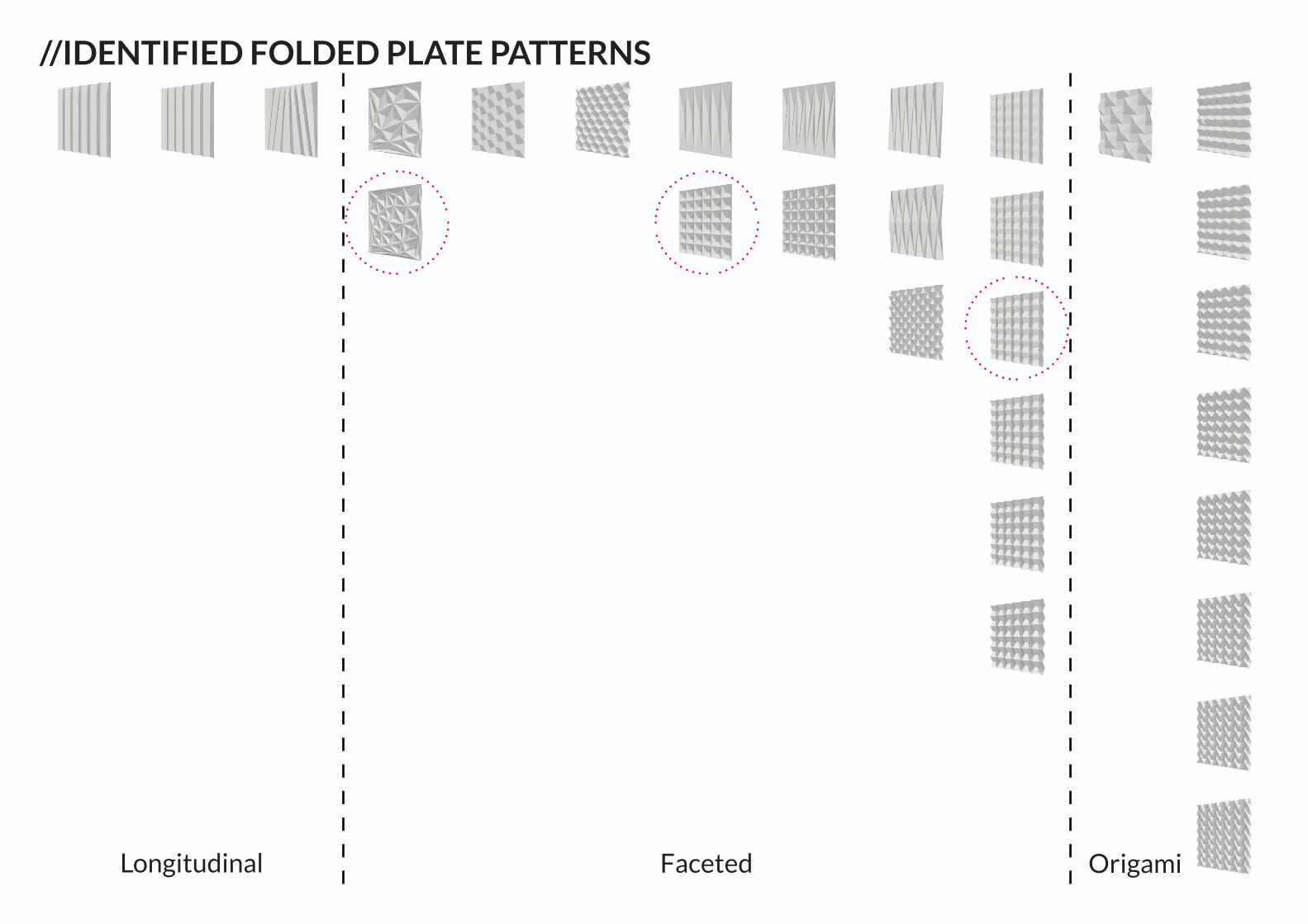
Longitudinal Faceted Origami
//IDENTIFIED FOLDED PLATE PATTERNS
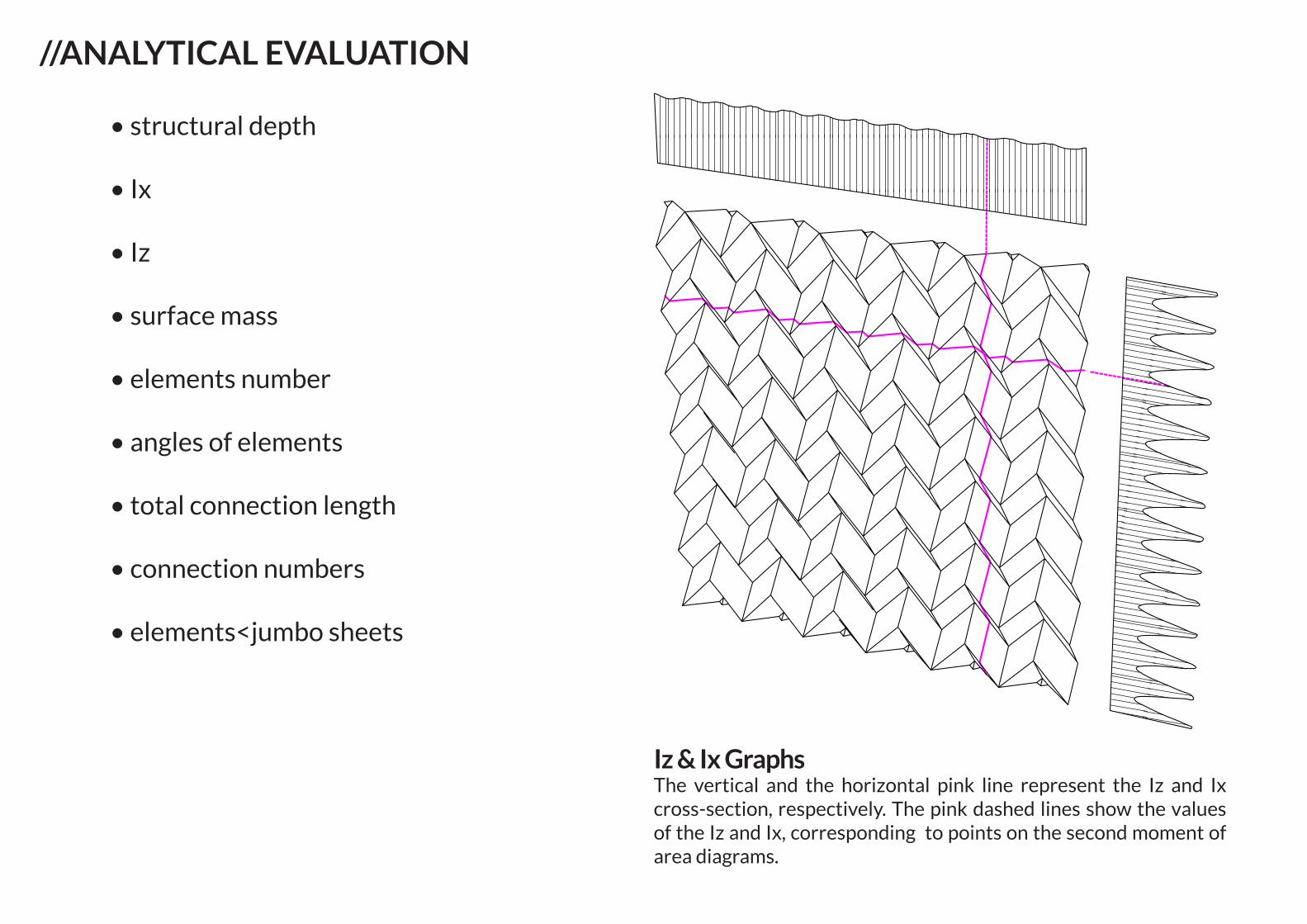
• structural depth
• Ix
• Iz
• surface mass
• elements number
• angles of elements
• total connection length
• connection numbers
• elements<jumbo sheets
//ANALYTICAL EVALUATION
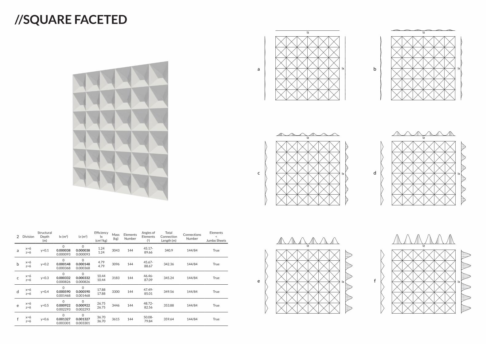
Iz & Ix GraphsThe vertical and the horizontal pink line represent the Iz and Ix cross-section, respectively. The pink dashed lines show the values of the Iz and Ix, corresponding to points on the second moment of area diagrams.
Iz
Ixa b
c d
e f
Iz
Ix
Iz
Ix
Iz
Ix
Iz
Ix
Iz
Ix
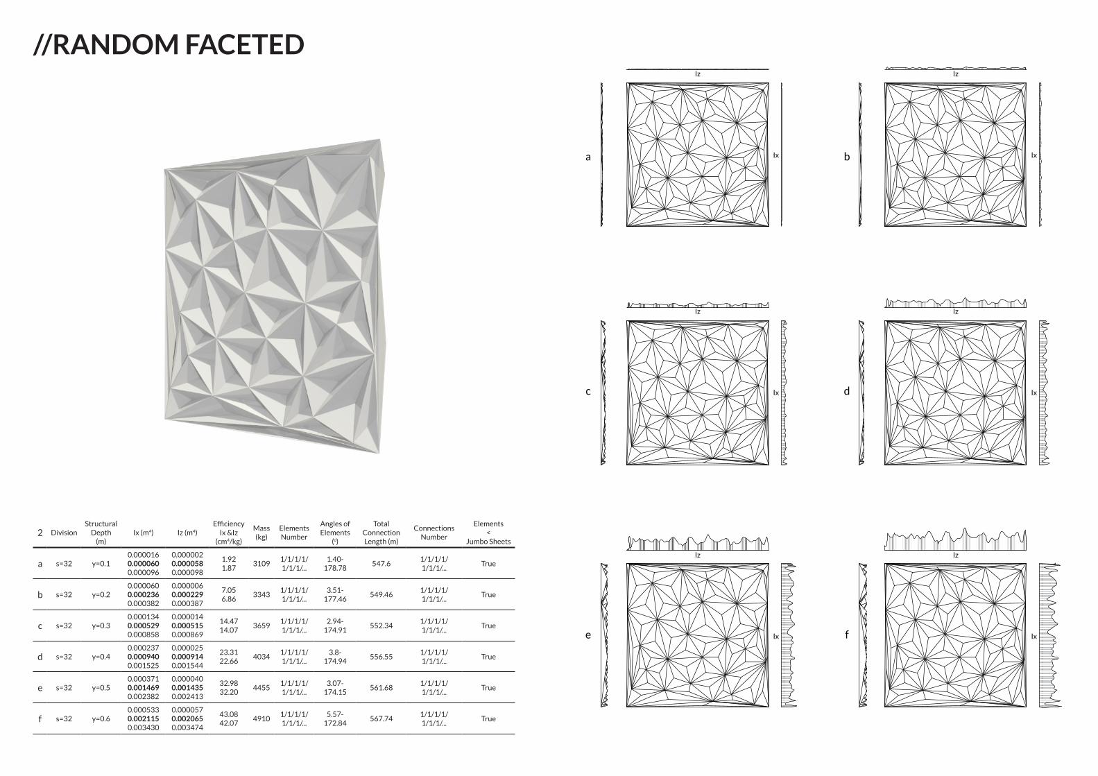
2 DivisionStructural
Depth (m)
Ix (m4) Iz (m4)Efficiency
Ix &Iz(cm4/kg)
Mass (kg)
Elements Number
Angles of Elements
(o)
Total Connection Length (m)
Connections Number
Elements <
Jumbo Sheets
a s=32 y=0.10.0000160.0000600.000096
0.0000020.0000580.000098
1.921.87
31091/1/1/1/1/1/1/...
1.40-178.78
547.61/1/1/1/1/1/1/...
True
b s=32 y=0.20.0000600.0002360.000382
0.0000060.0002290.000387
7.056.86
33431/1/1/1/1/1/1/...
3.51-177.46
549.461/1/1/1/1/1/1/...
True
c s=32 y=0.30.0001340.0005290.000858
0.0000140.0005150.000869
14.4714.07
36591/1/1/1/1/1/1/...
2.94-174.91
552.341/1/1/1/1/1/1/...
True
d s=32 y=0.40.0002370.0009400.001525
0.0000250.0009140.001544
23.3122.66
40341/1/1/1/1/1/1/...
3.8-174.94
556.551/1/1/1/1/1/1/...
True
e s=32 y=0.50.0003710.0014690.002382
0.0000400.0014350.002413
32.9832.20
44551/1/1/1/1/1/1/...
3.07-174.15
561.681/1/1/1/1/1/1/...
True
f s=32 y=0.60.0005330.0021150.003430
0.0000570.0020650.003474
43.0842.07
49101/1/1/1/1/1/1/...
5.57-172.84
567.741/1/1/1/1/1/1/...
True
//RANDOM FACETED
2 DivisionStructural
Depth (m)
Ix (m4) Iz (m4)Efficiency
Ix(cm4/kg)
Mass (kg)
Elements Number
Angles of Elements
(o)
Total Connection Length (m)
Connections Number
Elements <
Jumbo Sheets
ax=6z=6
y=0.10
0.0000380.000093
00.0000380.000093
1.241.24
3043 14445.17-89.66
340.9 144/84 True
bx=6z=6
y=0.20
0.0001480.000368
00.0001480.000368
4.794.79
3096 14445.67-88.67
342.36 144/84 True
cx=6z=6
y=0.30
0.0003320.000826
00.0003320.000826
10.4410.44
3183 14446.46-87.09
345.24 144/84 True
dx=6z=6
y=0.40
0.0005900.001468
00.0005900.001468
17.8817.88
3300 14447.49-85.01
349.56 144/84 True
ex=6z=6
y=0.50
0.0009220.002293
00.0009220.002293
26.7526.75
3446 14448.72-82.56
353.88 144/84 True
fx=6z=6
y=0.60
0.0013270.003301
00.0013270.003301
36.7036.70
3615 14450.08-79.84
359.64 144/84 True
Iz
Ixa b
c d
e f
Iz
Ix
Iz
Ix
Iz
Ix
Iz
Ix
Iz
Ix
//SQUARE FACETED
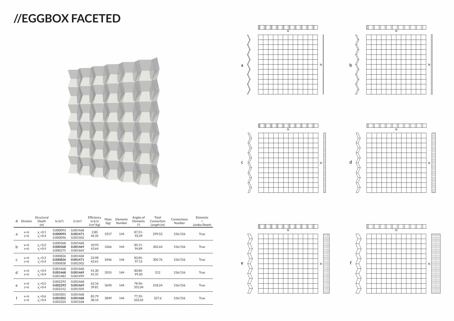
//EGGBOX FACETEDIz
Ixa b
c d
e f
Iz
Ix
Iz
Ix
Iz
Ix
Iz
Ix
Iz
Ix
4 DivisionStructural
Depth (m)
Ix (m4) Iz (m4)Efficiency
Ix & Iz(cm4/kg)
Mass (kg)
Elements Number
Angles of Elements
(o)
Total Connection Length (m)
Connections Number
Elements <
Jumbo Sheets
ax=6z=6
yx=0.1
yz=0.4
0.0000930.0000930.000096
0.0014680.0014710.001502
2.8044.35
3317 14487.51-92.49
299.52 156/156 True
bx=6z=6
yx=0.2
yz=0.4
0.0003680.0003680.000375
0.0014680.0014690.001469
10.9343.64
3366 14485.11-94.89
302.64 156/156 True
cx=6z=6
yx=0.3
yz=0.4
0.0008260.0008260.000838
0.0014680.0014710.001502
23.9842.61
3446 14482.85-97.15
305.76 156/156 True
dx=6z=6
yx=0.4
yz=0.4
0.0014680.0014680.001483
0.0014680.0014690.001499
41.3041.31
3555 14480.80-99.20
312 156/156 True
ex=6z=6
yx=0.5
yz=0.4
0.0022930.0022930.002312
0.0014680.0014690.001509
62.1639.81
3690 14478.96-101.04
318.24 156/156 True
fx=6z=6
yx=0.6
yz=0.4
0.0033010.0033020.003324
0.0014680.0014680.001568
85.7938.14
3849 14477.35-102.65
327.6 156/156 True
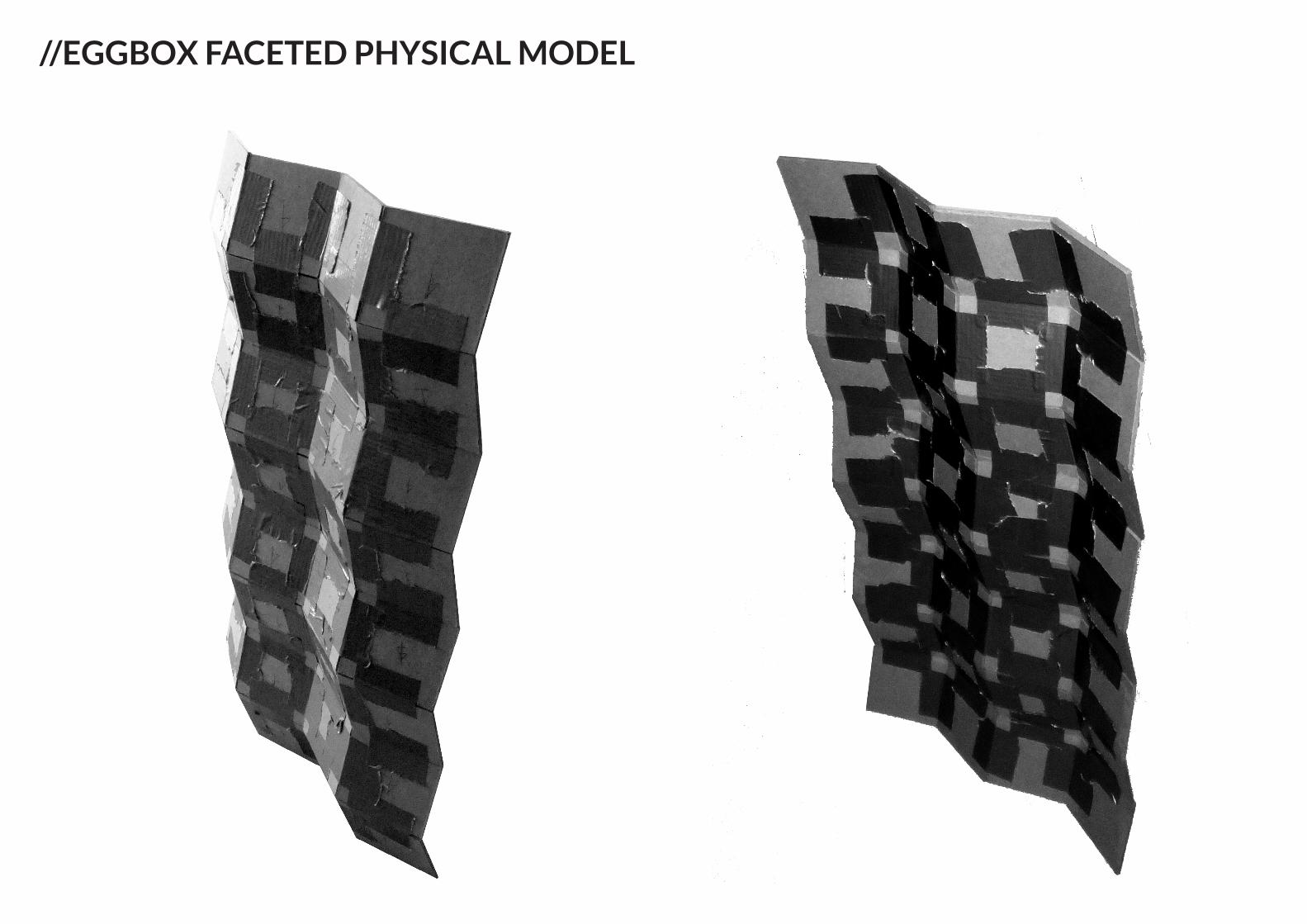
//EGGBOX FACETED PHYSICAL MODEL
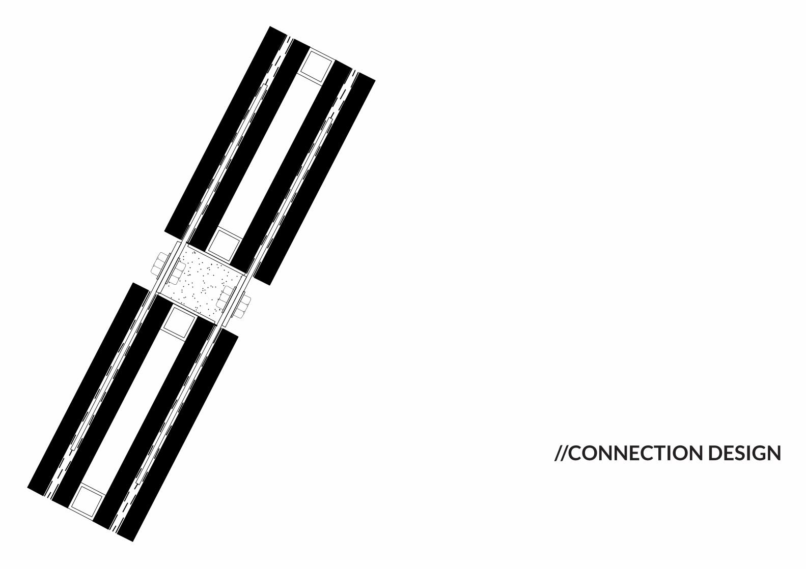
//CONNECTION DESIGN
θ
d
L
Μ max
F
F
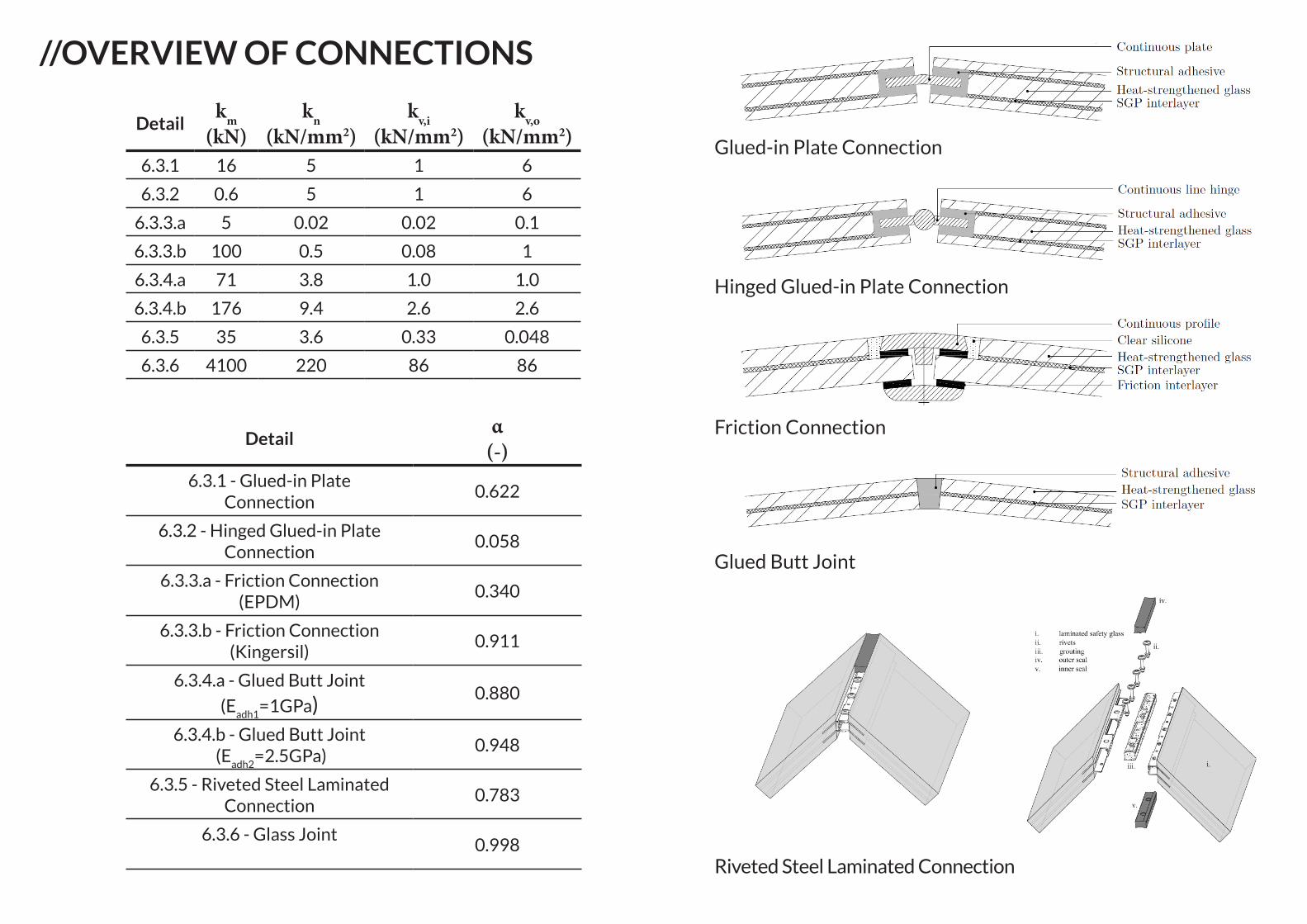
Glued-in Plate Connection
Hinged Glued-in Plate Connection
Friction Connection
Glued Butt Joint
Riveted Steel Laminated Connection
Detailkm(kN)
kn(kN/mm2)
kv,i(kN/mm2)
kv,o(kN/mm2)
6.3.1 16 5 1 6
6.3.2 0.6 5 1 6
6.3.3.a 5 0.02 0.02 0.1
6.3.3.b 100 0.5 0.08 1
6.3.4.a 71 3.8 1.0 1.0
6.3.4.b 176 9.4 2.6 2.6
6.3.5 35 3.6 0.33 0.048
6.3.6 4100 220 86 86
//OVERVIEW OF CONNECTIONS
Detailα(-)
6.3.1 - Glued-in Plate Connection
0.622
6.3.2 - Hinged Glued-in Plate Connection
0.058
6.3.3.a - Friction Connection (EPDM)
0.340
6.3.3.b - Friction Connection (Kingersil)
0.911
6.3.4.a - Glued Butt Joint
(Eadh1
=1GPa)0.880
6.3.4.b - Glued Butt Joint (E
adh2=2.5GPa)
0.948
6.3.5 - Riveted Steel Laminated Connection
0.783
6.3.6 - Glass Joint0.998
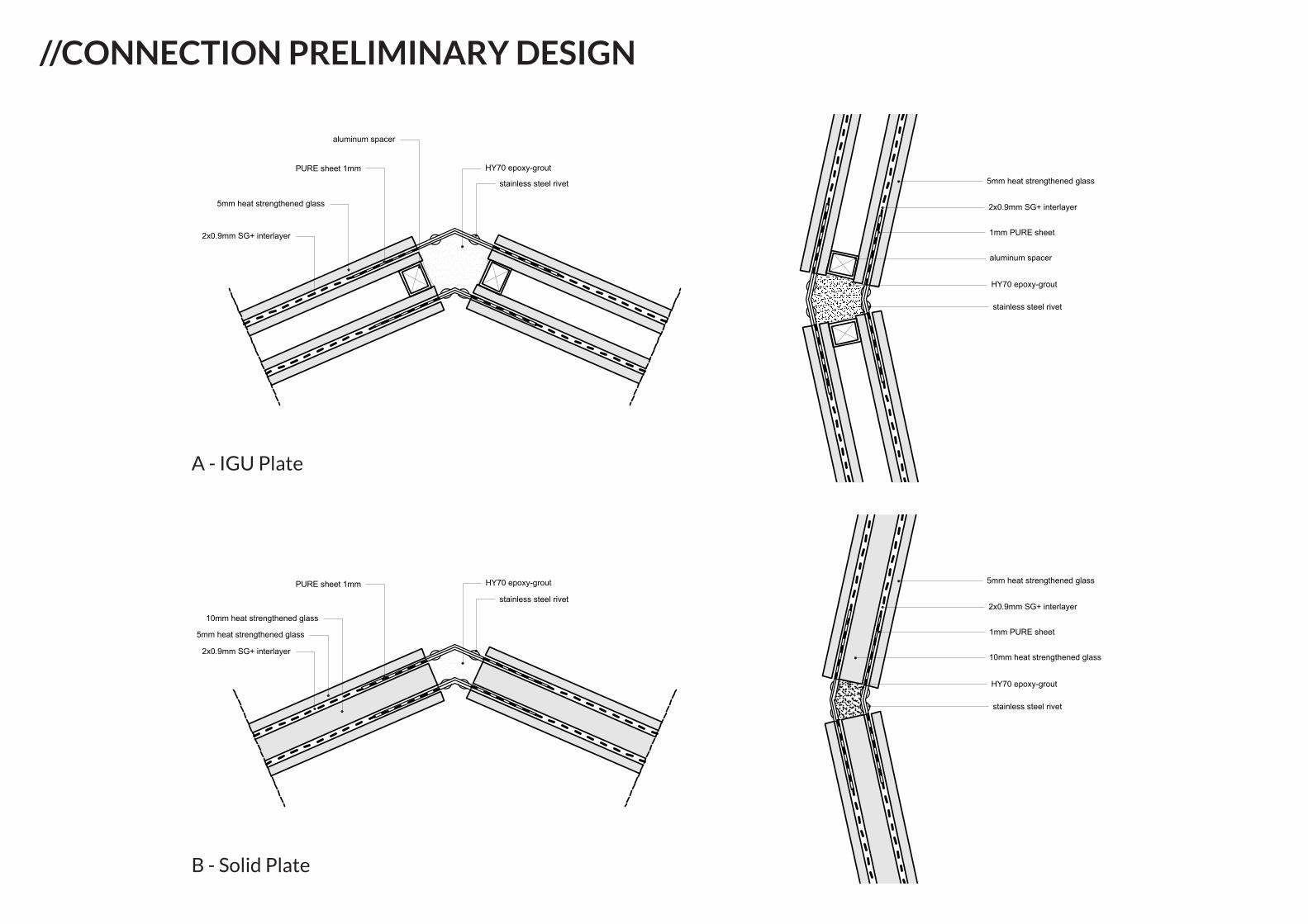
5mm heat strengthened glass
2x0.9mm SG+ interlayer
PURE sheet 1mm
stainless steel rivet
HY70 epoxy-grout
5mm heat strengthened glass
2x0.9mm SG+ interlayer
PURE sheet 1mm
stainless steel rivet
HY70 epoxy-grout
10mm heat strengthened glass
aluminum spacer
5mm heat strengthened glass
2x0.9mm SG+ interlayer
1mm PURE sheet
aluminum spacer
HY70 epoxy-grout
stainless steel rivet
5mm heat strengthened glass
2x0.9mm SG+ interlayer
1mm PURE sheet
10mm heat strengthened glass
HY70 epoxy-grout
stainless steel rivet
5mm heat strengthened glass
2x0.9mm SG+ interlayer
PURE sheet 1mm
stainless steel rivet
HY70 epoxy-grout
5mm heat strengthened glass
2x0.9mm SG+ interlayer
PURE sheet 1mm
stainless steel rivet
HY70 epoxy-grout
10mm heat strengthened glass
aluminum spacer
5mm heat strengthened glass
2x0.9mm SG+ interlayer
1mm PURE sheet
aluminum spacer
HY70 epoxy-grout
stainless steel rivet
5mm heat strengthened glass
2x0.9mm SG+ interlayer
1mm PURE sheet
10mm heat strengthened glass
HY70 epoxy-grout
stainless steel rivet
//CONNECTION PRELIMINARY DESIGN
B - Solid Plate
A - IGU Plate
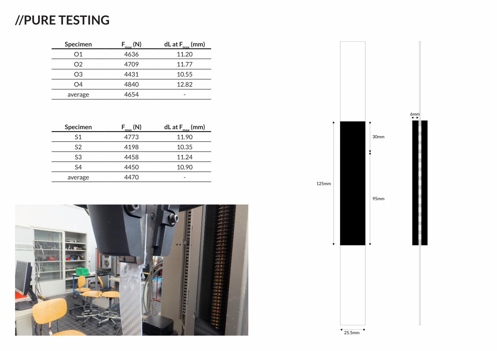
Specimen Fmax
(N) dL at Fmax
(mm)
O1 4636 11.20
O2 4709 11.77
O3 4431 10.55
O4 4840 12.82
average 4654 -
Specimen Fmax
(N) dL at Fmax
(mm)
S1 4773 11.90
S2 4198 10.35
S3 4458 11.24
S4 4450 10.90
average 4470 -
25.5mm
125mm
30mm
95mm
6mm
//PURE TESTING
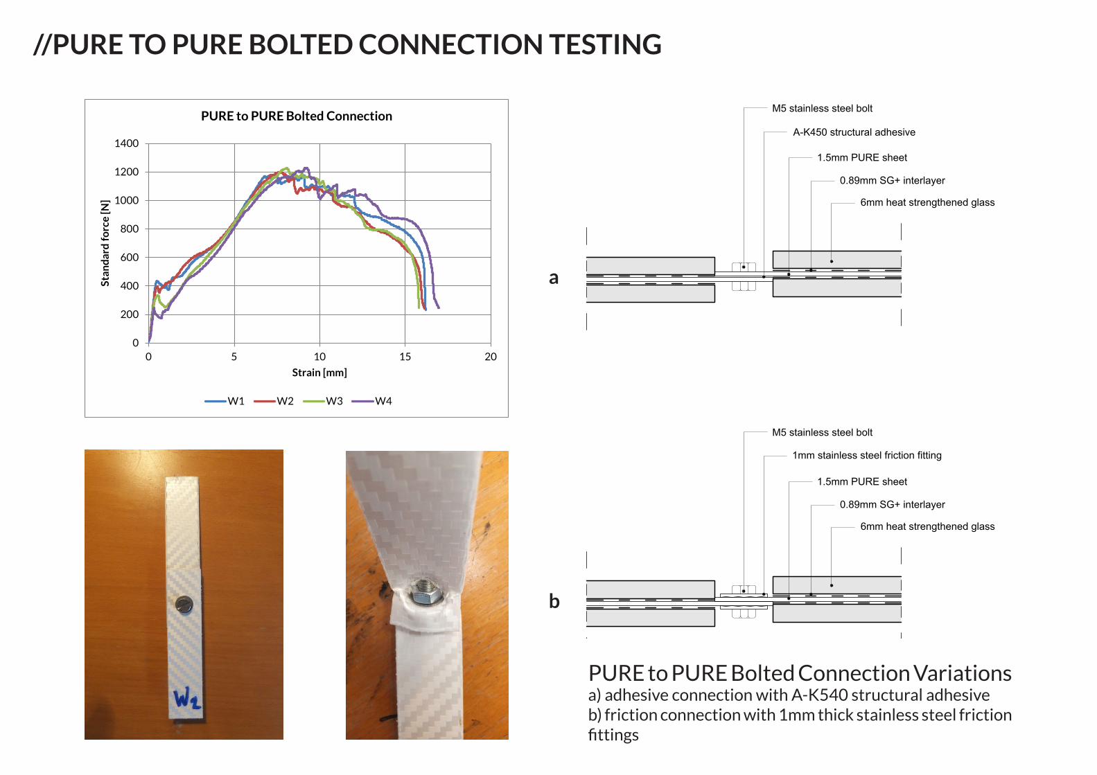
//PURE TO PURE BOLTED CONNECTION TESTING
0
200
400
600
800
1000
1200
1400
0 5 10 15 20
Stan
dar
d f
orc
e [N
]
Strain [mm]
PURE to PURE Bolted Connection
W1 W2 W3 W4
PURE to PURE Bolted Connection Variations a) adhesive connection with A-K540 structural adhesiveb) friction connection with 1mm thick stainless steel friction fittings
6mm heat strengthened glass
0.89mm SG+ interlayer
1.5mm PURE sheet
A-K450 structural adhesive
M5 stainless steel bolt
6mm heat strengthened glass
0.89mm SG+ interlayer
1.5mm PURE sheet
1mm stainless steel friction fitting
M5 stainless steel bolt
a
b
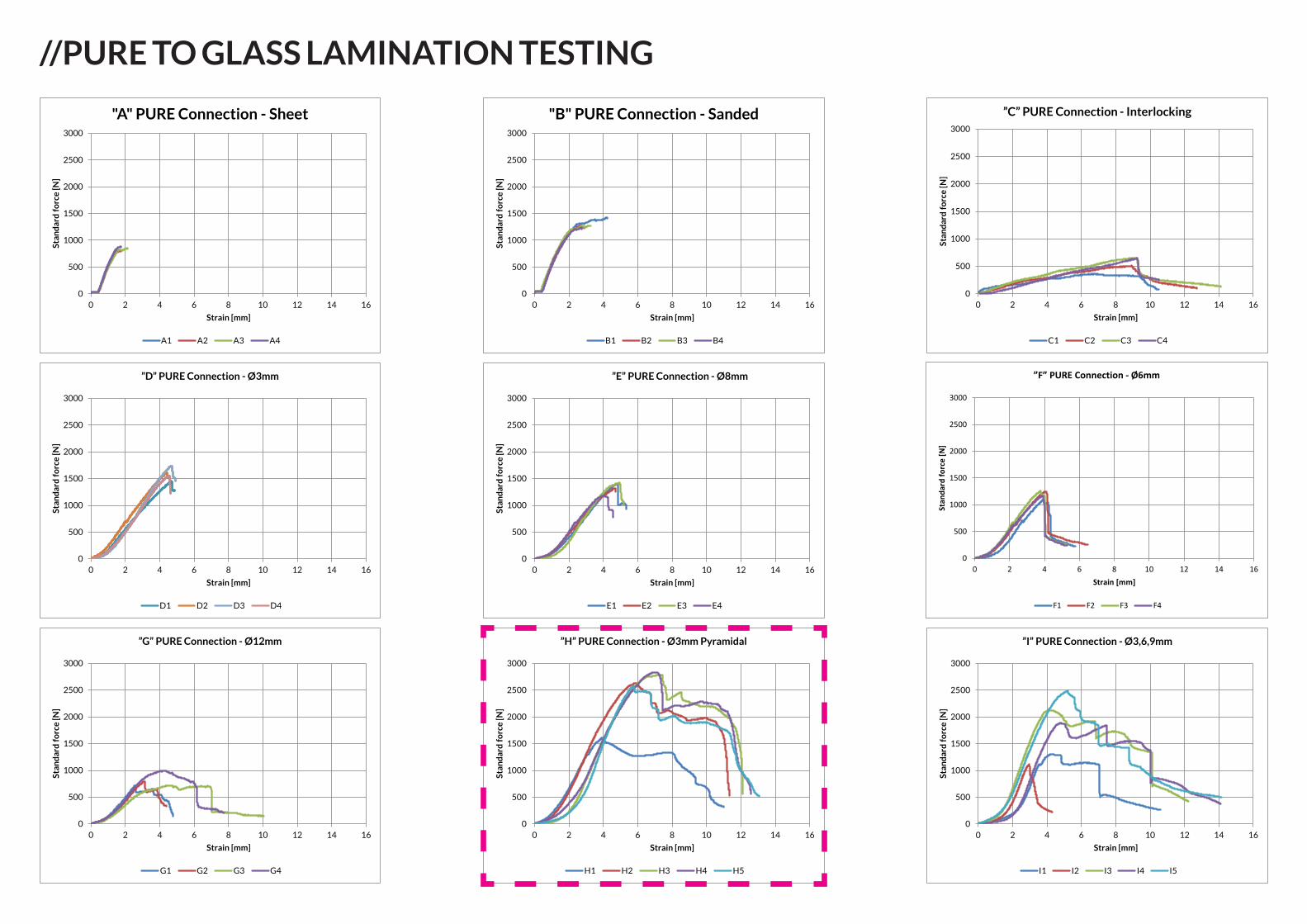
//PURE TO GLASS LAMINATION TESTING
0
500
1000
1500
2000
2500
3000
0 2 4 6 8 10 12 14 16
Stan
dar
d f
orc
e [N
]
Strain [mm]
"A" PURE Connection - Sheet
A1 A2 A3 A4
0
500
1000
1500
2000
2500
3000
0 2 4 6 8 10 12 14 16
Stan
dar
d f
orc
e [N
]
Strain [mm]
"B" PURE Connection - Sanded
B1 B2 B3 B4
0
500
1000
1500
2000
2500
3000
0 2 4 6 8 10 12 14 16
Stan
dar
d f
orc
e [N
]
Strain [mm]
”D” PURE Connection - Ø3mm
D1 D2 D3 D4
0
500
1000
1500
2000
2500
3000
0 2 4 6 8 10 12 14 16
Stan
dar
d f
orc
e [N
]
Strain [mm]
”C” PURE Connection - Interlocking
C1 C2 C3 C4
0
500
1000
1500
2000
2500
3000
0 2 4 6 8 10 12 14 16
Stan
dar
d f
orc
e [N
]
Strain [mm]
”E” PURE Connection - Ø8mm
E1 E2 E3 E4
0
500
1000
1500
2000
2500
3000
0 2 4 6 8 10 12 14 16
Stan
dard
forc
e [N
]
Strain [mm]
”F” PURE Connection - Ø6mm
F1 F2 F3 F4
0
500
1000
1500
2000
2500
3000
0 2 4 6 8 10 12 14 16
Stan
dar
d f
orc
e [N
]
Strain [mm]
”G” PURE Connection - Ø12mm
G1 G2 G3 G4
0
500
1000
1500
2000
2500
3000
0 2 4 6 8 10 12 14 16
Stan
dar
d f
orc
e [N
]
Strain [mm]
”H” PURE Connection - Ø3mm Pyramidal
H1 H2 H3 H4 H5
0
500
1000
1500
2000
2500
3000
0 2 4 6 8 10 12 14 16
Stan
dar
d f
orc
e [N
]
Strain [mm]
”I” PURE Connection - Ø3,6,9mm
I1 I2 I3 I4 I5
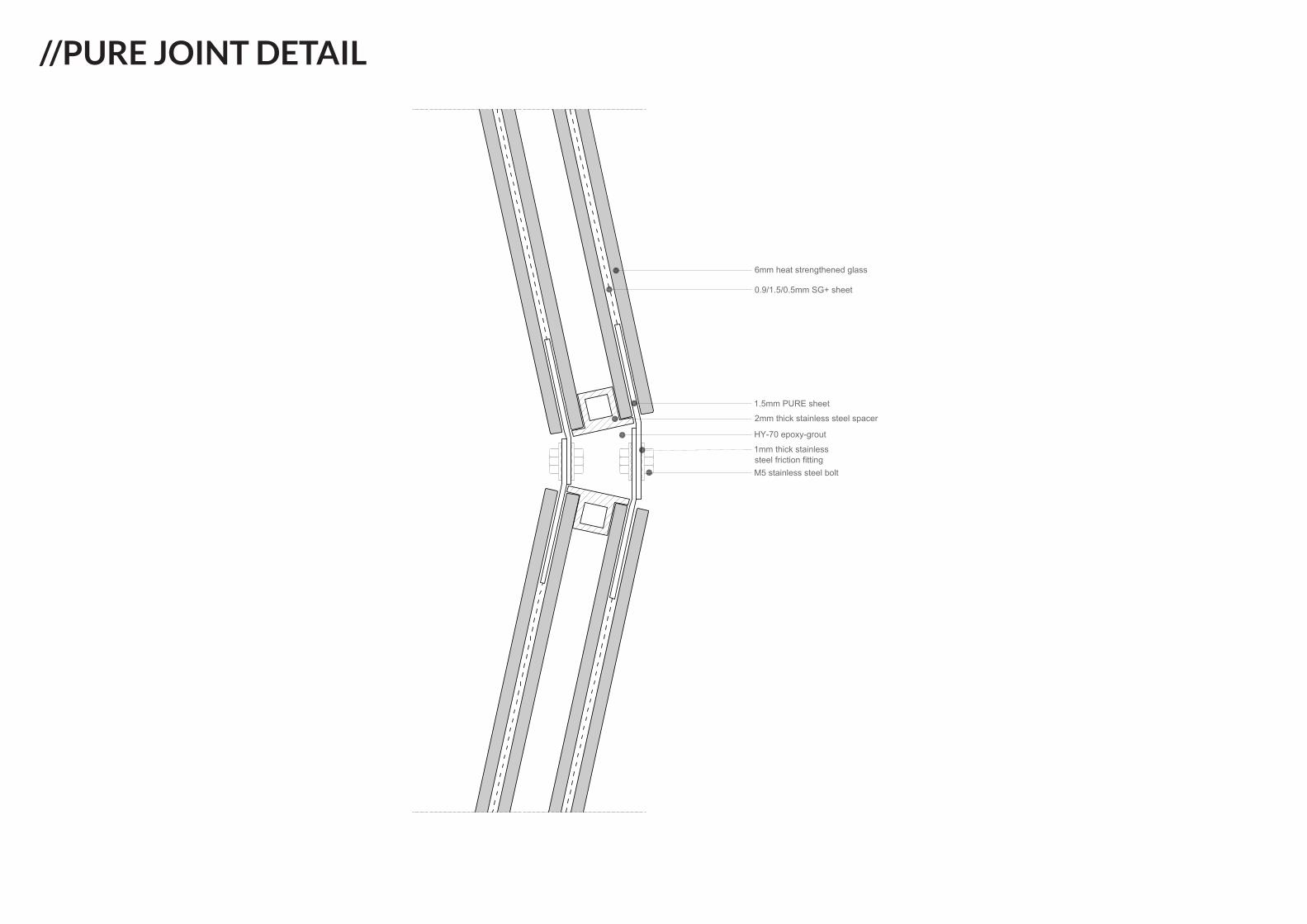
//PURE JOINT DETAIL
6mm heat strengthened glass
0.9/1.5/0.5mm SG+ sheet
1.5mm PURE sheet
2mm thick stainless steel spacer
HY-70 epoxy-grout
1mm thick stainlesssteel friction fittingM5 stainless steel bolt
θd
L
Μmax
F
F
0
200
400
600
800
1000
1200
1400
1600
1800
2000
00 .050 .1 0.15 0.20 .250 .3
Mom
ent
[Nm
/m]
Rotation [rad]
"P" PURE Joint
P1 P2 P3 P4
1100
0.095 0.0960.088
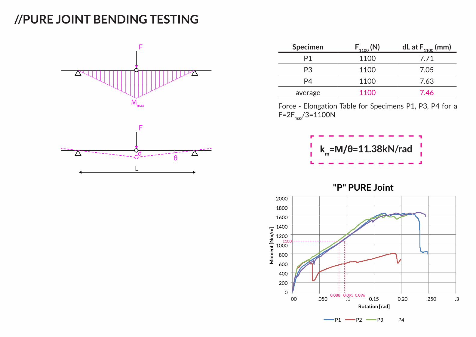
//PURE JOINT BENDING TESTING
Force - Elongation Table for Specimens P1, P3, P4 for a F=2F
max/3=1100N
Specimen F1100
(N) dL at F1100
(mm)
P1 1100 7.71
P3 1100 7.05
P4 1100 7.63
average 1100 7.46
km=M/θ=11.38kN/rad

//PURE JOINT BENDING TESTING
Detailα(-)
6.3.1 - Glued-in Plate Connection 0.6226.3.2 - Hinged Glued-in Plate Connection 0.058
6.3.3.a - Friction Connection (EPDM) 0.3406.3.3.b - Friction Connection (Kingersil) 0.9116.3.4.a - Glued Butt Joint (E
adh1=1GPa) 0.880
6.3.4.b - Glued Butt Joint (Eadh2
=2.5GPa) 0.9486.3.5 - Riveted Steel Laminated Connection 0.783
6.3.6 - Glass Joint 0.9986.6.1 - PURE Joint 0.549
Analysis 1E=3286N/mm2t=6.28mm
Analysis 3E=3350N/mm2t=7mm
Analysis 5E=3700N/mm2t=7mm
Analysis 7E=3630N/mm2t=7mm
Analysis 2 E=3286N/mm2t=7mm
Analysis 4E=3500N/mm2t=7mm
Analysis 6E=3650N/mm2t=7mm
Analysis 8E=3635N/mm2t=7mm
d=11.4mm
d=8.10mm
d=7.33mm
d=7.47mm
d=8.26mm
d=7.75mm
d=7.43mm
d=7.46mm
}
}
}
}
}
}
}
}
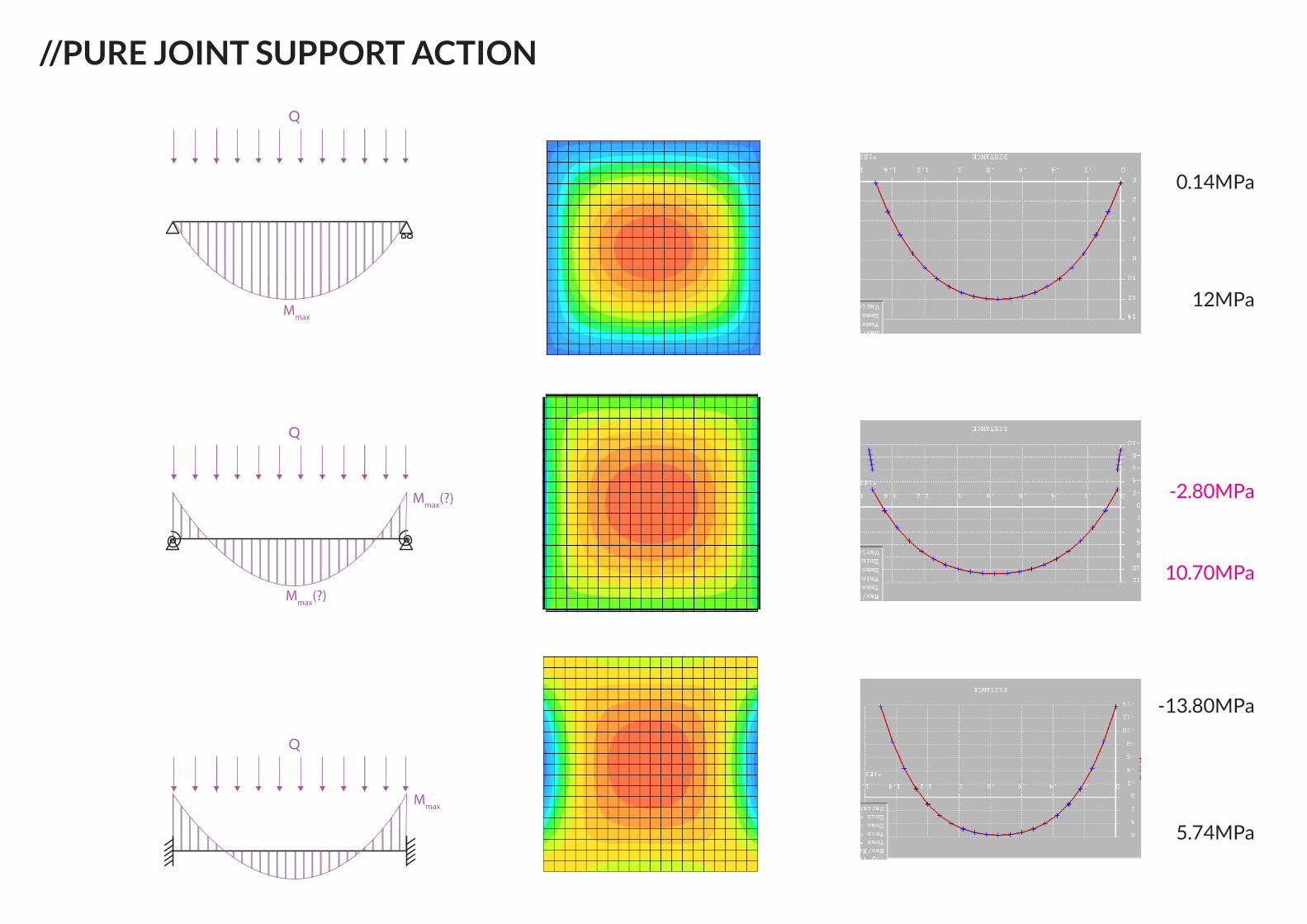
//PURE JOINT SUPPORT ACTION
Μmax
Q
Q
Μmax(?)
Μmax(?)
Q
Μmax
0.14MPa
12MPa
-2.80MPa
10.70MPa
-13.80MPa
5.74MPa
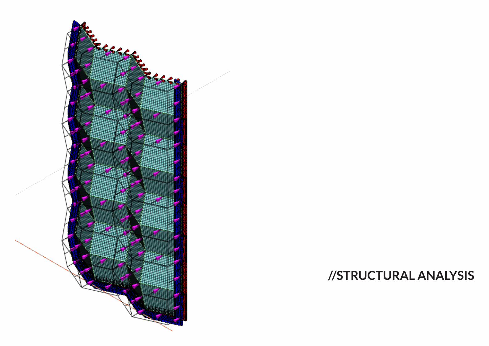
//STRUCTURAL ANALYSIS
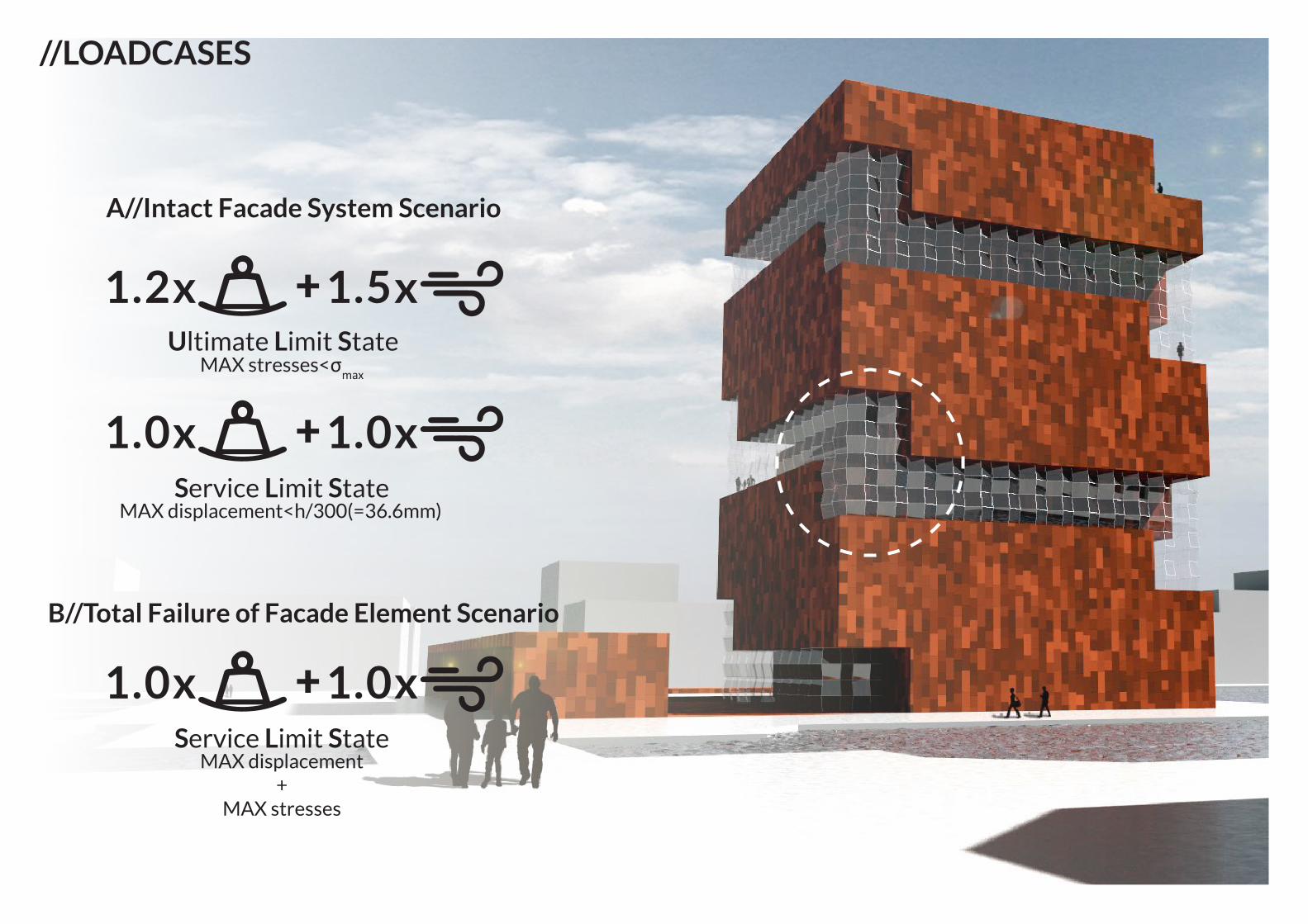
+1.2x 1.5x
+1.0x 1.0x
+1.0x 1.0x
Service Limit State
Service Limit State
Ultimate Limit State
//LOADCASES
MAX displacement +
MAX stresses
MAX displacement<h/300(=36.6mm)
MAX stresses<σmax
A//Intact Facade System Scenario
B//Total Failure of Facade Element Scenario
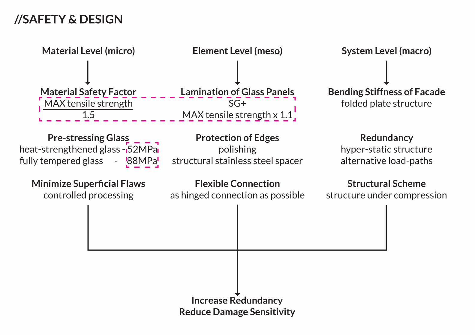
//SAFETY & DESIGN
Material Level (micro)
Material Safety FactorMAX tensile strength
1.5
Pre-stressing Glassheat-strengthened glass - 52MPafully tempered glass - 88MPa
Minimize Superficial Flawscontrolled processing
Lamination of Glass PanelsSG+
MAX tensile strength x 1.1
Protection of Edgespolishing
structural stainless steel spacer
Flexible Connectionas hinged connection as possible
Bending Stiffness of Facadefolded plate structure
Redundancyhyper-static structurealternative load-paths
Structural Schemestructure under compression
Element Level (meso) System Level (macro)
Increase RedundancyReduce Damage Sensitivity
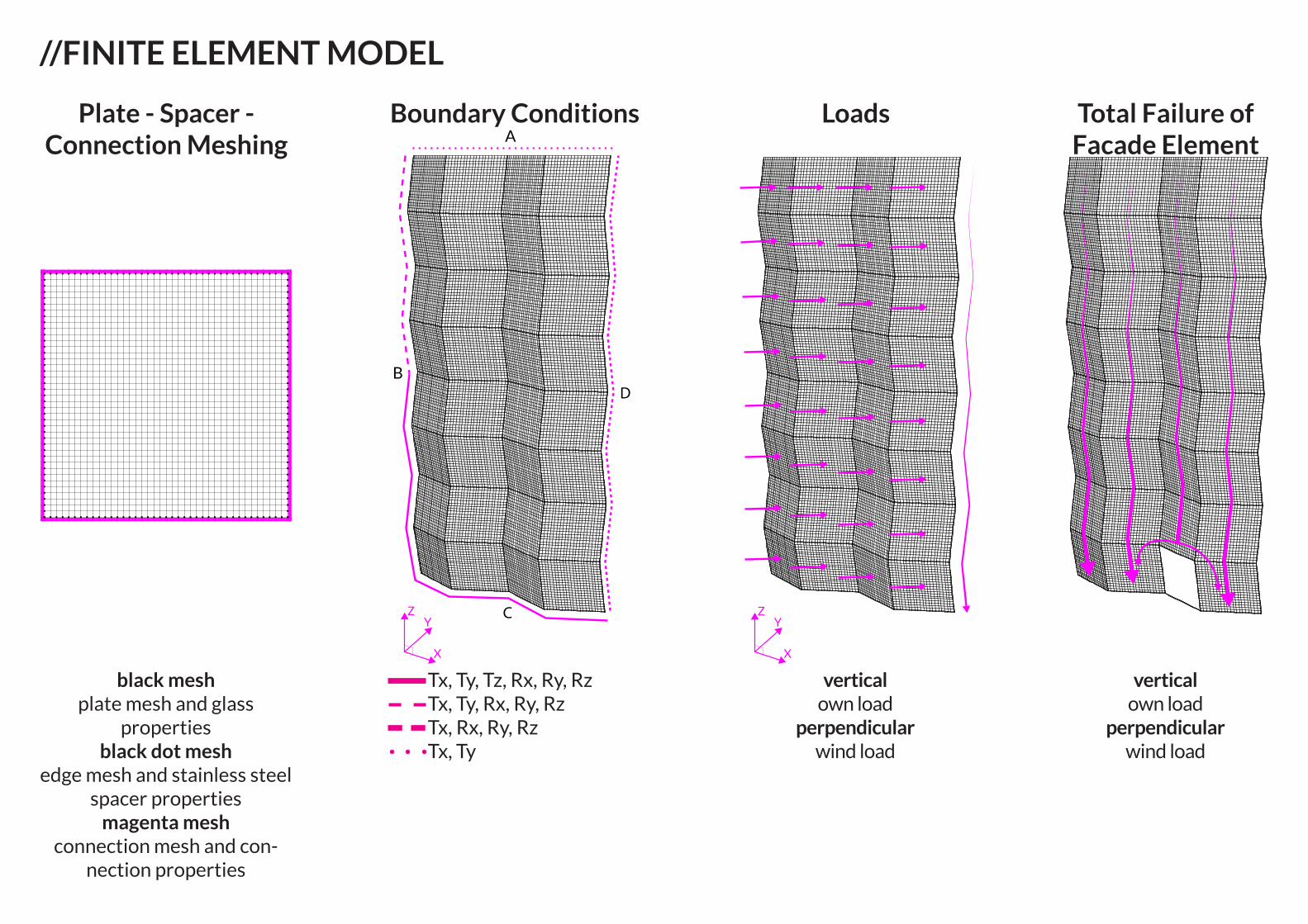
//FINITE ELEMENT MODEL
A
D
C
B
X
ZY
X
ZY
black meshplate mesh and glass
propertiesblack dot mesh
edge mesh and stainless steel spacer properties
magenta meshconnection mesh and con-
nection properties
Tx, Ty, Tz, Rx, Ry, Rz Tx, Ty, Rx, Ry, Rz Tx, Rx, Ry, Rz Tx, Ty
vertical own load
perpendicularwind load
vertical own load
perpendicularwind load
Total Failure of Facade Element
LoadsBoundary ConditionsPlate - Spacer - Connection Meshing
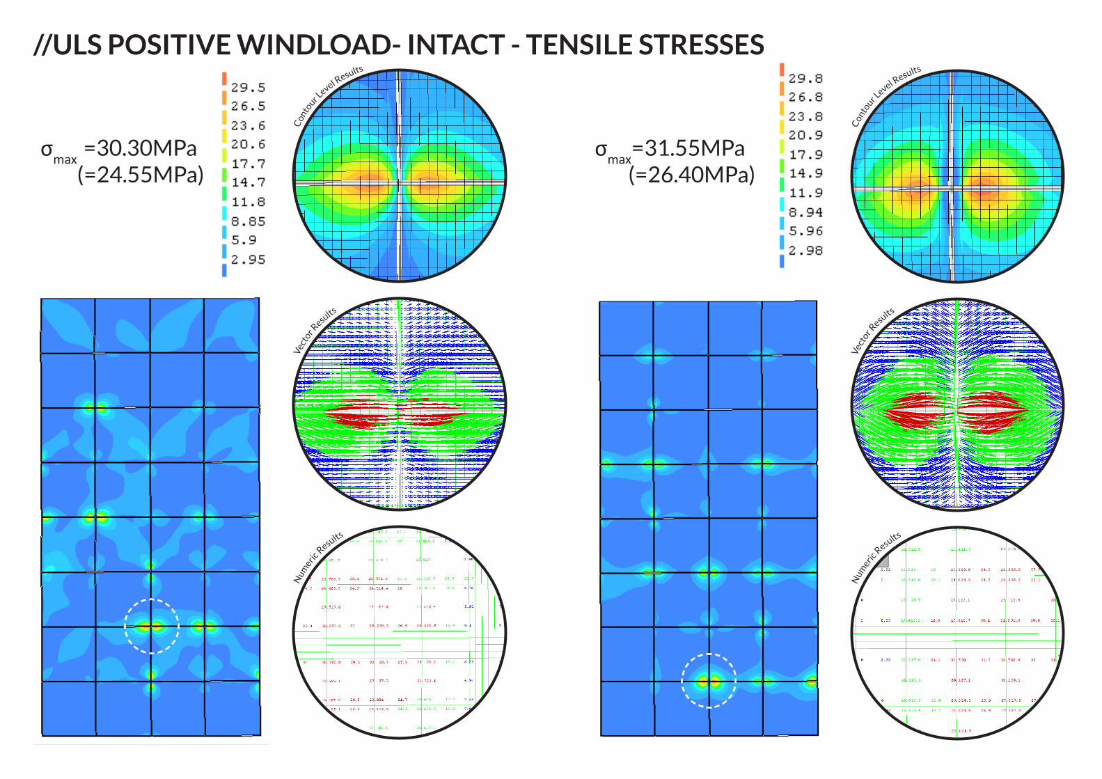
//ULS POSITIVE WINDLOAD- INTACT - TENSILE STRESSES
Con
tour L
evel Results
Vec
tor R
esults
Num
eric R
esults
Con
tour L
evel Results
Vec
tor R
esults
Num
eric R
esults
σmax =30.30MPa(=24.55MPa)
σmax=31.55MPa(=26.40MPa)
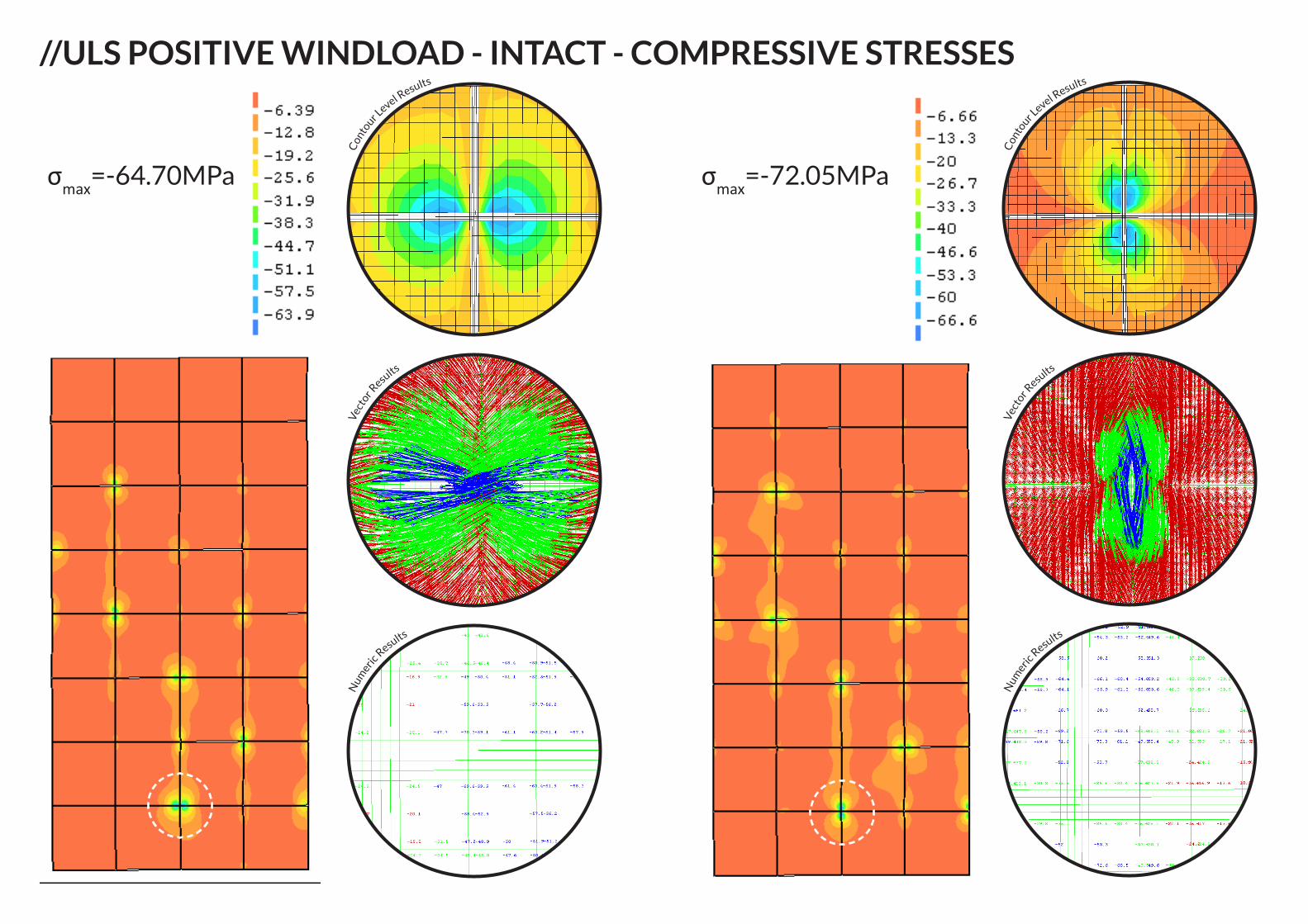
//ULS POSITIVE WINDLOAD - INTACT - COMPRESSIVE STRESSES
Con
tour L
evel Results
Vec
tor R
esults
Num
eric R
esults
Con
tour L
evel Results
Vec
tor R
esults
Num
eric R
esults
σmax=-64.70MPa σmax=-72.05MPa
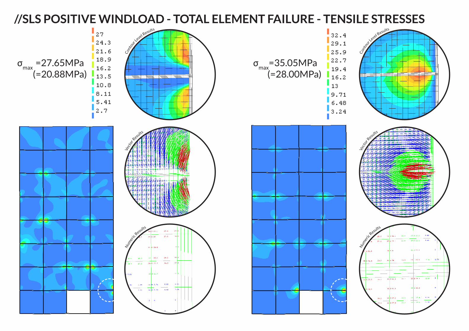
//SLS POSITIVE WINDLOAD - TOTAL ELEMENT FAILURE - TENSILE STRESSES
Con
tour L
evel Results
Vec
tor R
esults
Num
eric R
esults
Con
tour L
evel Results
Vec
tor R
esults
Num
eric R
esults
σmax =27.65MPa(=20.88MPa)
σmax=35.05MPa(=28.00MPa)
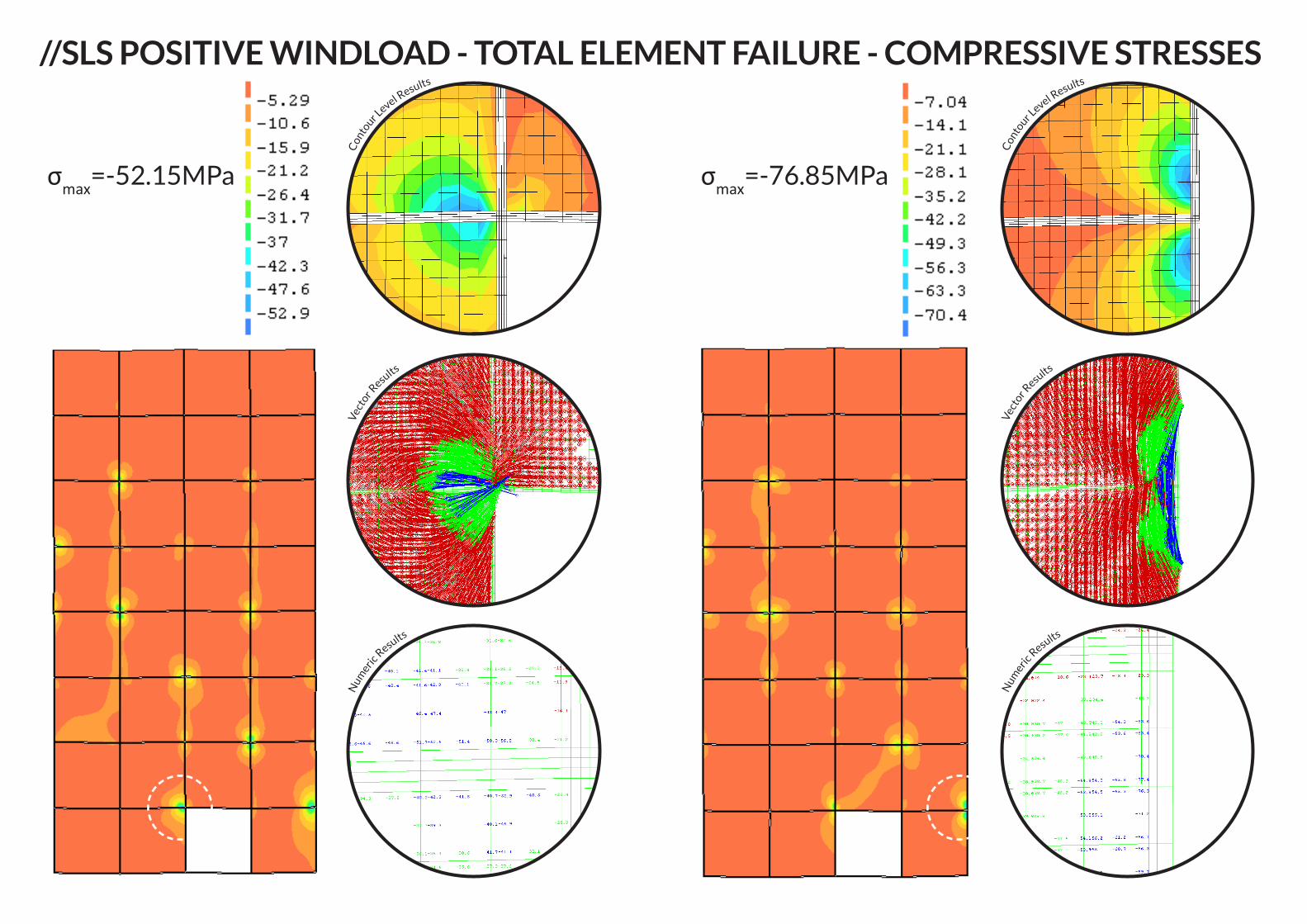
//SLS POSITIVE WINDLOAD - TOTAL ELEMENT FAILURE - COMPRESSIVE STRESSES
Con
tour L
evel Results
Vec
tor R
esults
Num
eric R
esults
Con
tour L
evel Results
Vec
tor R
esults
Num
eric R
esults
σmax=-52.15MPa σmax=-76.85MPa
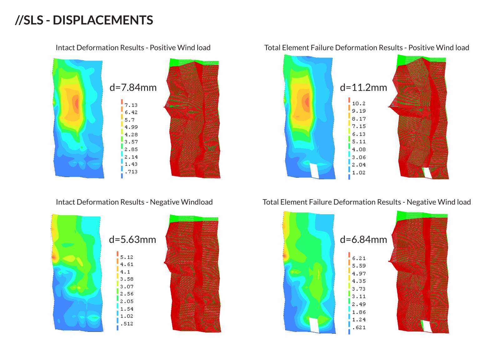
//SLS - DISPLACEMENTS
Intact Deformation Results - Positive Wind load Total Element Failure Deformation Results - Positive Wind load
Total Element Failure Deformation Results - Negative Wind loadIntact Deformation Results - Negative Windload
d=7.84mm d=11.2mm
d=5.63mm d=6.84mm
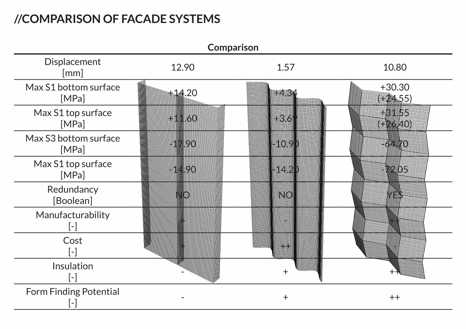
//COMPARISON OF FACADE SYSTEMS
Comparison
Displacement [mm]
12.90 1.57 10.80
Max S1 bottom surface [MPa]
+14.20 +4.34+30.30
(+24.55)
Max S1 top surface [MPa]
+11.60 +3.69+31.55
(+26.40)
Max S3 bottom surface [MPa]
-17.90 -10.90 -64.70
Max S1 top surface [MPa]
-14.90 -14.20 -72.05
Redundancy[Boolean]
NO NO YES
Manufacturability[-]
+ - ++
Cost[-]
+ ++ -
Insulation[-]
- + ++
Form Finding Potential[-]
- + ++
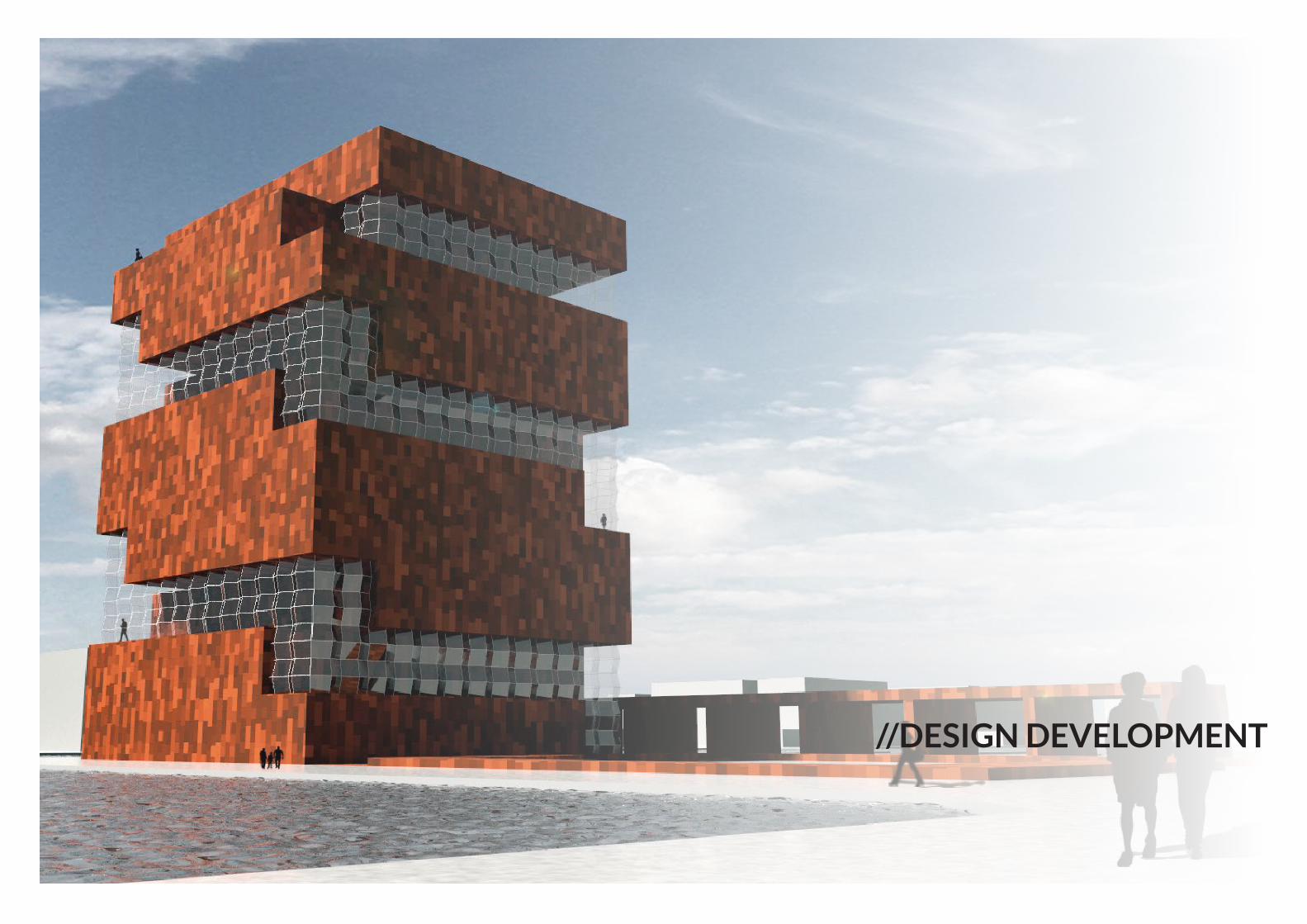
//DESIGN DEVELOPMENT
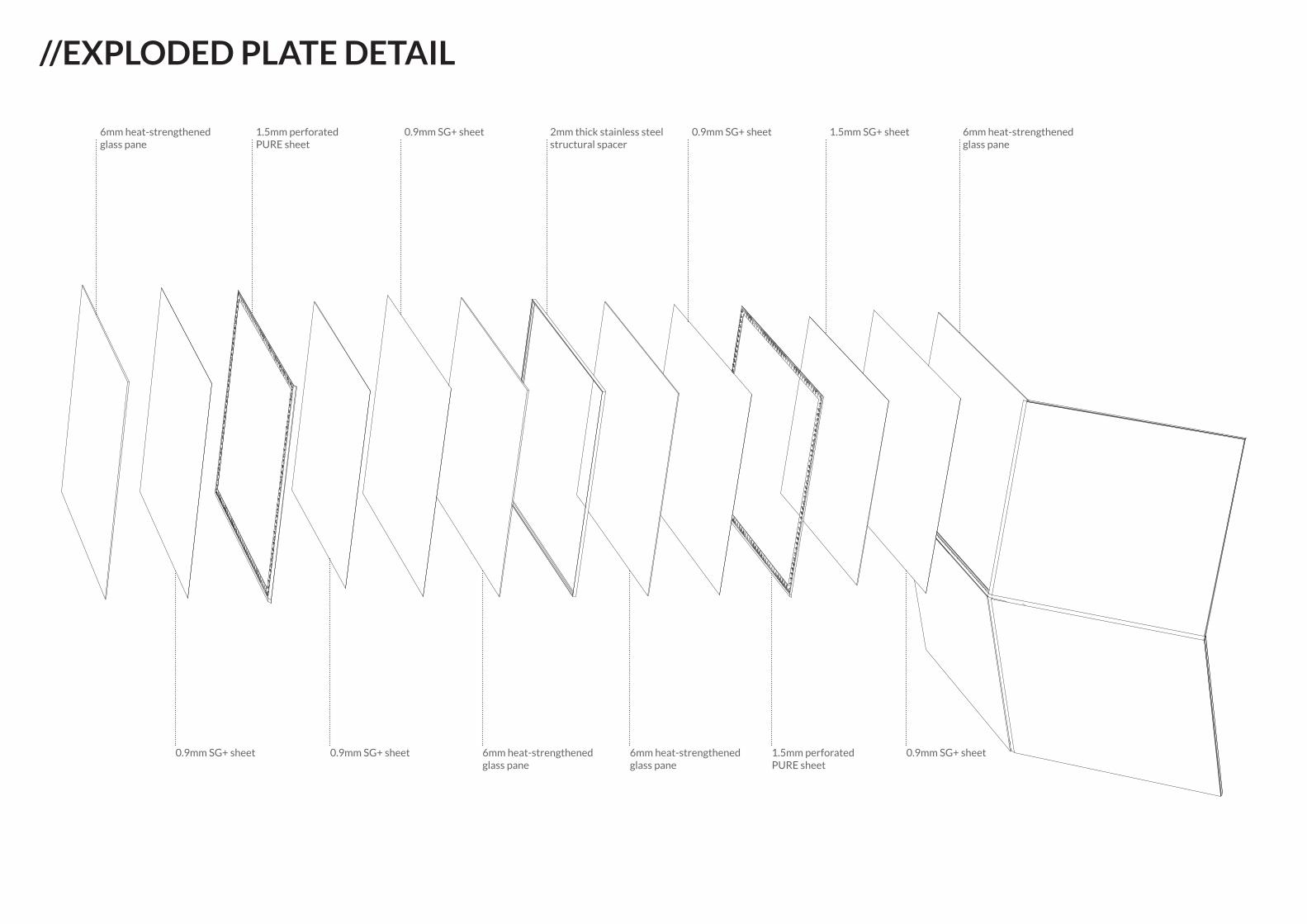
6mm heat-strengthened glass pane
0.9mm SG+ sheet 0.9mm SG+ sheet 6mm heat-strengthened glass pane
6mm heat-strengthened glass pane
1.5mm perforated PURE sheet
0.9mm SG+ sheet
1.5mm perforated PURE sheet
0.9mm SG+ sheet 2mm thick stainless steel structural spacer
0.9mm SG+ sheet 1.5mm SG+ sheet 6mm heat-strengthenedglass pane
//EXPLODED PLATE DETAIL
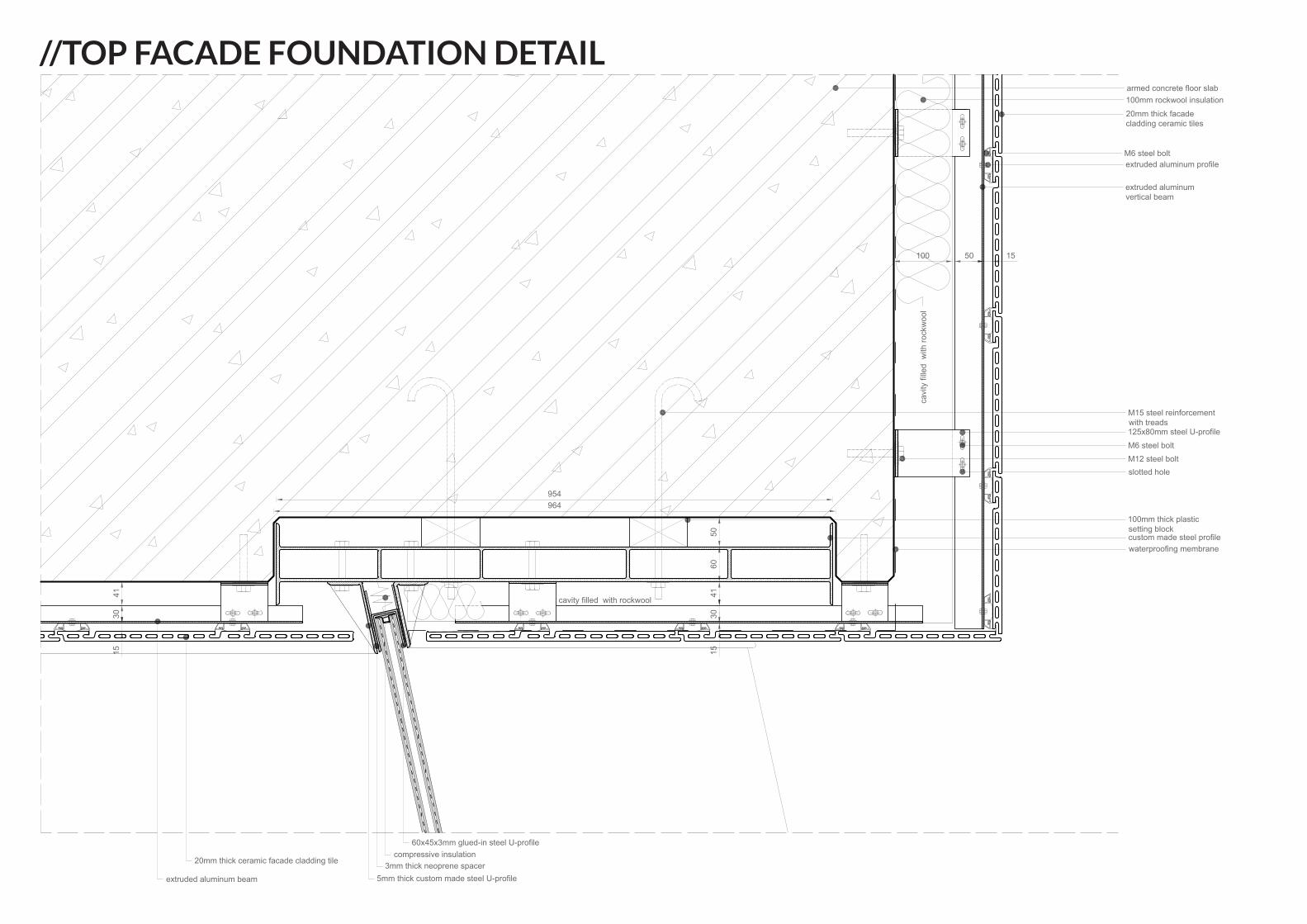
//TOP FACADE FOUNDATION DETAILarmed concrete floor slab100mm rockwool insulation20mm thick facadecladding ceramic tiles
extruded aluminum profileM6 steel bolt
extruded aluminumvertical beam
M6 steel bolt125x80mm steel U-profile
slotted holeM12 steel bolt
M15 steel reinforcementwith treads
100mm thick plasticsetting blockcustom made steel profilewaterproofing membrane
20mm thick ceramic facade cladding tile
extruded aluminum beam 5mm thick custom made steel U-profile3mm thick neoprene spacer
60x45x3mm glued-in steel U-profilecompressive insulation
cavi
ty fi
lled
with
rock
woo
l
cavity filled with rockwool
964954
5060
4130
15
4130
15
100 50 15
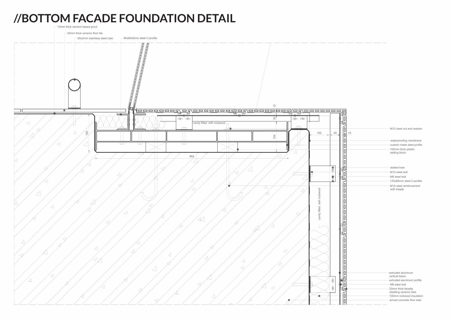
armed concrete floor slab100mm rockwool insulation
20mm thick facadecladding ceramic tiles
extruded aluminum profileM6 steel bolt
extruded aluminumvertical beam
M6 steel bolt125x80mm steel U-profile
slotted holeM12 steel bolt
cavi
ty fi
lled
with
rock
woo
l M15 steel reinforcementwith treads
100mm thick plasticsetting block
custom made steel profile
cavity filled with rockwool
waterproofing membrane
M12 steel nut and washer
60x2mm stainless steel tube
20mm thick ceramic floor tile
10mm thick cement based grout
80x60x5mm steel U-profile
964
190 100 50 15
154
3015
//BOTTOM FACADE FOUNDATION DETAIL
Conclusions Recommendations
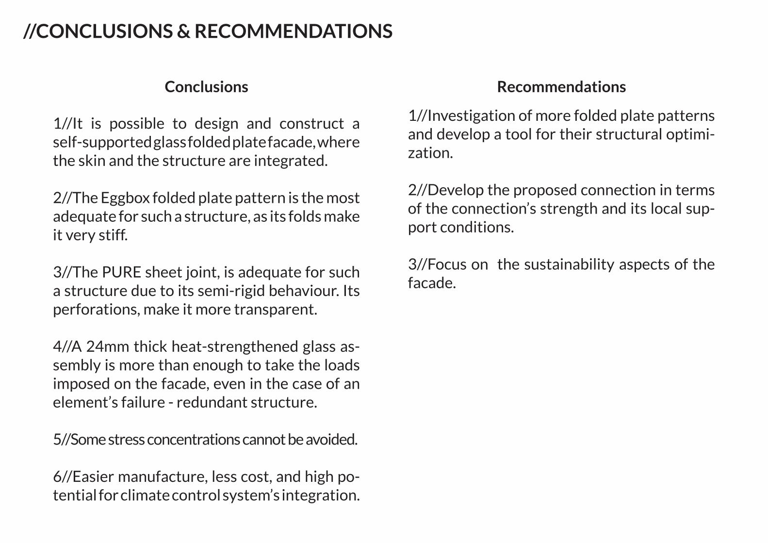
//CONCLUSIONS & RECOMMENDATIONS
1//It is possible to design and construct a self-supported glass folded plate facade, where the skin and the structure are integrated.
2//The Eggbox folded plate pattern is the most adequate for such a structure, as its folds make it very stiff.
3//The PURE sheet joint, is adequate for such a structure due to its semi-rigid behaviour. Its perforations, make it more transparent.
4//A 24mm thick heat-strengthened glass as-sembly is more than enough to take the loads imposed on the facade, even in the case of an element’s failure - redundant structure.
5//Some stress concentrations cannot be avoided.
6//Easier manufacture, less cost, and high po-tential for climate control system’s integration.
1//Investigation of more folded plate patterns and develop a tool for their structural optimi-zation.
2//Develop the proposed connection in terms of the connection’s strength and its local sup-port conditions.
3//Focus on the sustainability aspects of the facade.
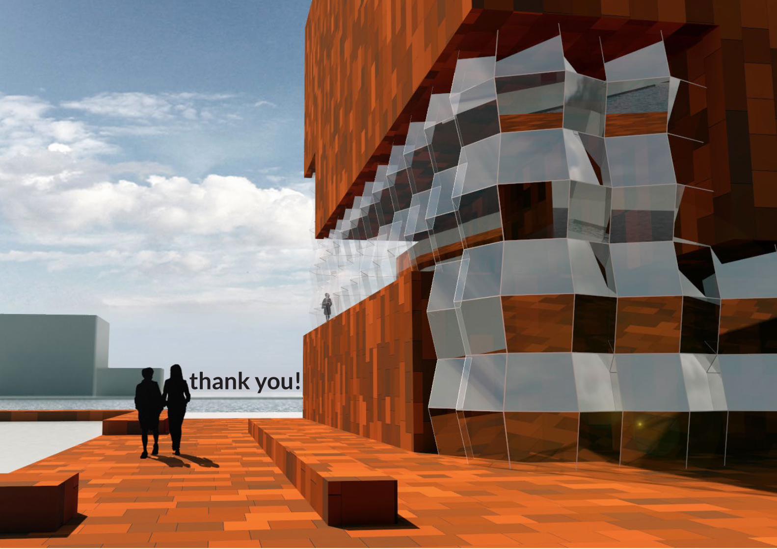
thank you!