Embed Size (px)
Citation preview
1
Autumn 2015 Volume 6
Issue 3
15 Promotional Logo Coin Bank Mark Maclean-Blevins
18 Designers’ Corner, Rotational Molding, Part 14 Rotationally Molded Holes -- Part 1 – Types Glenn L. Beall
22 Engineers can’t (and shouldn’t) do everything Gordon Grob
26 James Karlin Dedication
The Journal Product Design and Development Division
Newsletter
2
Autumn 2015 Volume 6
Issue 3
Editor’s Desk My Two Cents Worth
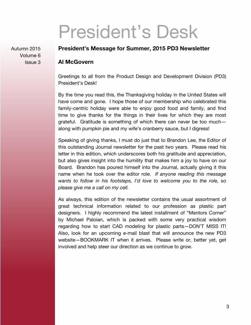
Brandon Lee
After two years of editing the Journal, it is now time to move on. Being editor has been a great experience. I have had the chance to work with some fantastic people and publish what I hope is a decent piece of journalism. I feel that after two years, I’ve gotten a bit stale and I need a break to get some perspective with regards to the Journal.
Thanks to my loyal readers. You are the reason the Journal exists.
Also, I’d to thank the following people who have helped create the Journal. First I’d like to thank Michael Palonian for not only championing my cause, and volunteering to write the mentor column, but for seeking me out and convincing me to be editor of the Journal. To Glenn Beall for delivering the articles on rotational molding like clockwork and telling me that being editor of the newsletter is the “best job” in the division. For the councilor reports, the two excellent case studies, plus additional articles, and especially his support of the Journal, Mark Maclean-Blevins thank you. To both David Tucker and Jeremy Braaten for their tireless work on the board of directors minutes and the membership report. In addition, thanks to Eric R. Larson P.E. for sharing his insightful blogs on plastic design. Finally, to our president- Al McGovern- thank you for proofreading every Journal so thoroughly. Al is the reason why the Journal reads so well. His mastery of grammar is second to none.
I wish you all a wonderful holiday. Best to you all.
Brandon Lee Editor-in-Chief [email protected] PD3
Disclaimer: The editorial content published in this newsletter is the sole responsibility of the authors. The Product Development & Design Division publishes this content for the use and benefit of its members, and is not responsible for the accuracy or validity of editorial content contributed by various sources
3
Autumn 2015 Volume 6
Issue 3
President’s Desk President’s Message for Summer, 2015 PD3 Newsletter
Al McGovern
Greetings to all from the Product Design and Development Division (PD3) President’s Desk!
By the time you read this, the Thanksgiving holiday in the United States will have come and gone. I hope those of our membership who celebrated this family-centric holiday were able to enjoy good food and family, and find time to give thanks for the things in their lives for which they are most grateful. Gratitude is something of which there can never be too much—along with pumpkin pie and my wife’s cranberry sauce, but I digress!
Speaking of giving thanks, I must do just that to Brandon Lee, the Editor of this outstanding Journal newsletter for the past two years. Please read his letter in this edition, which underscores both his gratitude and appreciation, but also gives insight into the humility that makes him a joy to have on our Board. Brandon has poured himself into the Journal, actually giving it this name when he took over the editor role. If anyone reading this message wants to follow in his footsteps, I’d love to welcome you to the role, so please give me a call on my cell.
As always, this edition of the newsletter contains the usual assortment of great technical information related to our profession as plastic part designers. I highly recommend the latest installment of “Mentors Corner” by Michael Paloian, which is packed with some very practical wisdom regarding how to start CAD modeling for plastic parts—DON’T MISS IT! Also, look for an upcoming e-mail blast that will announce the new PD3 website—BOOKMARK IT when it arrives. Please write or, better yet, get involved and help steer our direction as we continue to grow.
4
Autumn 2015 Volume 6
Issue 3
As always, I wish you peace and happiness in all you do,
Al McGovern President, Product Design and Development Division Naperville, IL +1-630-660-6217 [email protected] PD3
5
Autumn 2015 Volume 6
Issue 3
Boardroom Board of Directors Meeting, September 16, 2015
David Tucker
Attendees: Glenn Beall, Lance Neward, Mark Maclean Blevins, Michael Paloian, David Tucker, Ed Probst, Eric Larson, Kenneth Pawlak, Larry Schneider, Kristen Charlton, and Jeremy Braaten.
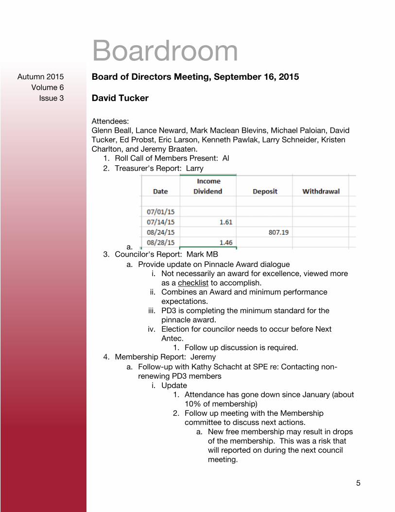
1. Roll Call of Members Present: Al 2. Treasurer's Report: Larry
a. 3. Councilor's Report: Mark MB
a. Provide update on Pinnacle Award dialogue i. Not necessarily an award for excellence, viewed more
as a checklist to accomplish. ii. Combines an Award and minimum performance
expectations. iii. PD3 is completing the minimum standard for the
pinnacle award. iv. Election for councilor needs to occur before Next
Antec. 1. Follow up discussion is required.
4. Membership Report: Jeremy a. Follow-up with Kathy Schacht at SPE re: Contacting non-
renewing PD3 members i. Update
1. Attendance has gone down since January (about 10% of membership)
2. Follow up meeting with the Membership committee to discuss next actions.
a. New free membership may result in drops of the membership. This was a risk that will reported on during the next council meeting.
6
Autumn 2015 Volume 6
Issue 3
b. Students can get full access to the society (reported at Antec)
5. Newsletter Report: a. Next Journal Issue—Fall
i. Target release date is October 31, 2015 ii. Kristin Charlton to work with Brandon on transition
plans iii. Open invitation to get content to Brandon for the next
newsletter. b. When will this edition be published? Perhaps put a link on our
new PD3 website 6. Committee Discussion
a. Website Committee: Al, Brandon, Mark MB, Mike Lacey, David Tucker
i. Committee has met twice over the summer--David will update on activities
1. Put in treasures name. 2. David to set-up discussion with Michael to
discuss transition of website URL. ii. Reference Desk plans--David to describe
1. Curation of content on the internet, endorsed by SPE PD3 members.
b. Top Con Committee: Ed, Mike Lacey, Lance, Michael P, Eric, Glenn (consult)
i. January Topcon to be postponed. 1. Presenters needed to step away from
presentation to due schedule conflict. 2. Follow-up for secondary plan by the next Board
Meeting ii. Joint SPE/IDSA “Designing with Plastics Conference"
1. Will be in Rhode Island at the School of Design the Summer of 2016
2. Follow-up discussion to be scheduled 7. New Business
a. Glenn Beall proposal for selling his plastic part design IM magazine articles to PD3 for perpetual use by the organization.
i. Accepted motion to have Glenn Beall develop articles for the newsletter and website.
ii. Follow-up discussion to be scheduled. b. Awards nominations--due this Friday, 9/18
i. Honored Member, SPE Fellow, International Leader, Business Management, Education, Research / Engineering Technology
ii. Respond to Al’s message to the group. c. Russell Broome request for PD3 financial support of SPE
7
Autumn 2015 Volume 6
Issue 3
Educational initiative i. Respond to email that was send to the board.
8. Old Business a. Review Action Register
9. Adjourn
David Tucker PD3 Secretary PD3
8
Autumn 2015 Volume 6
Issue 3
Councilor’s Desk Fall 2015 Council Meeting – October 9th – 11th, Pittsburgh, PA
Mark MacLean-Blevins
Council I Meeting: Positive overview from Wim DeVos and Dick Cameron – Council
organization for meetings has been making small active changes – engaging all members in small group problem thinking and solving related tasks. Council meeting structure with more break-out sessions seems here to stay – more gets accomplished and less time is wasted on rehashing old issues that do not move the Society forward.
Financial Report: The business model is changing and must continue to evolve. 15 years ago 35K paying members = $3.5 million revenue ANTEC with 4000 attendees = $2.0 million revenue HQ Staff = 35 people Today 14K members = $1.4 million revenue ANTEC with 1500 attendees = $0.8 million revenue HQ Staff = 12 people The new business model must produce new revenue stream that is non-dues revenue.
Sections, Divisions and CCOW Committee Meeting:
Sections – 2 new student chapters Sections – Several Sections placed on provisional status, a couple of
Sections abandoned. Divisions – Electrical and Electronics Division has been placed on
provisional status. CCOW – Large and long discussions revolving around report as
presented by the Governance Task Force. Mostly positive comments
9
Autumn 2015 Volume 6
Issue 3
and recommendations - most counselors who spoke tended to be supportive but offered ideas and thoughts for consideration, which were recorded by the GTF for review and use at their next work session.
Council II Meeting:
Student Activities Report: o All funding for student activities at ANTEC come from
funding raised by donations from Sections and Divisions only – no other sponsorship is requested.
o 111 students received travel awards at the 2015 ANTEC. Headquarters Communications Report: Several communications
tools and initiatives are being implemented by SPE including: Real Magnet Marketing Automation System, Industry Academia Collaboration, SPE/Paulson Training/Penn Tech collaboration, Credible, UL, and a refurbished Consultant’s Corner.
Council Elections Overview and Electronic Voting Proposal: EC last year moved the council elections from the fall/winter meeting to the first ANTEC council meeting. This eliminated the overlap of President elect positions. A new proposed electronic voting process that is being used by many other societies and associations, especially international associations was presented.
By-Laws Committee: By-Law 7.3 and 7.4, Articles 4 and 13, and Policies #002, 010,012, and 023 were changed, approved, and passed by Council.
Membership Report: Membership prior to e-Member introduction approximately 14K members - E-Members now number almost 3K.
New Business: o Discussion regarding the use and permanence of the red
version of the SPE logo – clarification that it is in Policy 009 and that it can be used and it is not a temporary logo.
o A motion was made and passed to add the red logo option into the SPE style guide.
Meeting was adjourned at 10:45 AM Respectfully Submitted 11 OCT 2015 Mark MacLean-Blevins PD3 Councilor PD3
10
Autumn 2015 Volume 6
Issue 3
Mentor’s Corner Detail Plastic Part Design
Michael Paloian
So far I’ve described the importance of completing proper product design research, establishing a comprehensive set of specifications, developing exploratory design concepts and refining a select group of those concepts to a more detailed level of realization. We are now ready to begin delving into detailed part design. This phase of design is the most time consuming, challenging and critical in the overall design process. It requires you to draw upon all your technical, creative, and personal skills to transform this abstract concept into a real product. Technical skills can be acquired with experience, knowledge, and study while creative and personal skills are unique to each of us. I don’t believe we can be taught to be creative nor can we change our personalities, but we can improve and modify these traits. The latter two qualities separate mediocre designers from great ones while also providing each of us with a personal stamp or signature. The translation of a concept into a real manufactured product is truly remarkable when you really think about it. Let’s now begin to investigate how technical, creative and personal skills provide the magic which transforms a thought into a physical mass produced plastic product.
We are at a phase in product design where we have a visual representation of the desired product and are faced with the challenge of segmenting that concept into specific parts which will satisfy all the product requirements. I think it’s appropriate to mention that there is no specific path or set of steps which must be followed in this process. The pathway and priorities depends on the product, schedule, budget, company, and financial resources available to you and the design team. However, I will try to describe a process which I’ve found to be appropriate for the hundreds of products which I have designed.
When I begin developing a production design I don’t think linearly, trying to solve a single detail at a time. I try to approach the design holistically by reviewing the overall product. I try to understand the basic objectives of the project as well as the overall purpose of the product. This perspective helps me establish a set of priorities which will be applied to decisions throughout
11
Autumn 2015 Volume 6
Issue 3
the design process. Most product design concepts at this level of development have defined an overall appearance based on a manufacturing process, component layout and segmentation of parts which form the seams throughout the overall form. At this point I review the overall shape and each part defined in the 3D concept model. This is a critical first step in the design translation since concepts often do not account for molding or assembly considerations and often require modification which will affect appearance. I also examine the proposed assembly of the product to be certain that the final design can be easily assembled and disassembled according to manufacturing requirements. All this is done before I begin any detailed CAD development.
If the overall design looks reasonable, I import the 3D concept geometry into a CAD program like SolidWorks or PTC Creo. The imported geometry of the external plastic covers is used as a template for creating the production part designs. Some designers have used this imported geometry for creating their individual parts instead of using it as a template. I strongly discourage anyone from doing this since it will result in a very sloppy CAD model which will be difficult to modify as the design is detailed. Models with non-parametric imported root features will eventually crash and require a complete rebuild. I strongly advise you to simply import the geometry as a template and completely rebuild a new parametric CAD model based on your CAD software.
My first step during this conversion process from concept to production design is to create a master model which is a solid 3D block representing the entire external plastic assembly. I’ve heard other terms used to describe this root geometry, but the purpose of creating a master model is always the same. A master model or single solid part representing the entire external shell of covers is one of the great benefits of parametric modeling. After a single overall form is created, it is used as the root geometry for creating all the individual parts. This will assure you that every part forming an external set of covers will perfectly align to the other. Changes made to the master model will automatically change the geometry of all associated parts. This powerful CAD modeling technique enables you to easily modify a design throughout the design process without concerns for misaligned parts. There are many critical considerations to take into account when creating a master model. One of the most important is the understanding of how parts will be molded and where the parting lines will be located relative to the fit of one part to another.
12
Autumn 2015 Volume 6
Issue 3
Defining split lines between covers is critical to the overall product design and is based on many considerations. Factors affecting split lines are based on aesthetic requirements defined by an industrial designer who may not be familiar with the associated technical parameters. When a master model is created, individual parts are defined by inserting surfaces to split the geometry into individual pieces. The location of surfaces is dictated by the aesthetic requirements set forth by the industrial designer as well as the optimum location for parting lines based on molding, ease of assembly (design for manufacturing, DFM), reliability, structural requirements and ease of service. This is a critical starting point in the design of plastic parts which will have a cascading effect on all subsequent features and details added to the part geometry.
Most CAD software requires you to add draft into the part geometry early in the history tree. If you attempt to add it when the part is almost completely designed you may discover you will be required to either roll back many features or completely rebuild the model. That is why it’s good practice to consider adding draft into the root geometry which is often the master model. Addition of draft to surfaces is critical to the entire plastic part design. I guarantee you that omitting draft in your part design will result in a disaster. Drafted surfaces will affect the overall appearance, fits and function of every part. The amount of draft will depend upon texture. Therefore these decisions must be made at the early stages of plastic part design. You cannot decide on the outside texture of set of plastic covers after the design is completed. Conversely, you must make that commitment before you finalize your split surfaces and account for all the draft angles. Typically one degree draft is required for any surface oriented in the direction of draw or the direction of how the mold is opened during part ejection. This is based on a smooth surface. When textures are applied to a surface undercuts are formed, requiring additional draft. Recommended additional draft is adding 1 degree of draft per .001” depth of texture added to the base 1 degree. In other words, a 2 mil (.002”) deep texture will require a minimum 3 degrees of draft.
A well planned master model is important. You don’t want to add too many features, yet you do want to capture the major critical features of the overall design. There are no hard and fast rules for creating an optimal master model. I think the best suggestion is to develop your own level of detail with experience. I personally try to only include product features which will influence an adjacent or mating part. Features contained within a part are omitted and added when that part is detailed as an individual component.

13
Autumn 2015 Volume 6
Issue 3
It’s appropriate to conclude at this point and begin discussing additional part design detailing in our next installment. By the way, this same methodology can be applied to the design of any plastic part. It is not exclusively limited to the design of injection molded parts. We use this technique for every process including pressure forming, rotational molding, composites etc. Master modeling is ideal for the design of any plastic product where there are many inter-related parts forming an overall surface or enclosure. We don’t apply this modeling method for internal structures or assemblages of components in machinery, mechanisms etc. Until next time, I hope you enjoyed this article and encourage you to email me with your comments, suggestions etc. at [email protected] or simply post your comments on my website:
https://www.idsys.com/blog/
Michael Palonian PD3 Mentor PD3
14
Autumn 2015 Volume 6
Issue 3
Gallery of Goofs The Picture Frame
Russ Malek
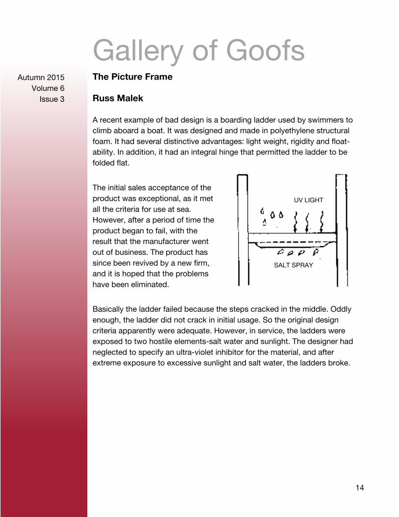
A recent example of bad design is a boarding ladder used by swimmers to climb aboard a boat. It was designed and made in polyethylene structural foam. It had several distinctive advantages: light weight, rigidity and float- ability. In addition, it had an integral hinge that permitted the ladder to be folded flat.
The initial sales acceptance of the product was exceptional, as it met all the criteria for use at sea. However, after a period of time the product began to fail, with the result that the manufacturer went out of business. The product has since been revived by a new firm, and it is hoped that the problems have been eliminated.
Basically the ladder failed because the steps cracked in the middle. Oddly enough, the ladder did not crack in initial usage. So the original design criteria apparently were adequate. However, in service, the ladders were exposed to two hostile elements-salt water and sunlight. The designer had neglected to specify an ultra-violet inhibitor for the material, and after extreme exposure to excessive sunlight and salt water, the ladders broke.
UV LIGHT
SALT SPRAY
15
Autumn 2015 Volume 6
Issue 3
Article Promotional Logo Coin Bank
Mark MacLean-Blevins
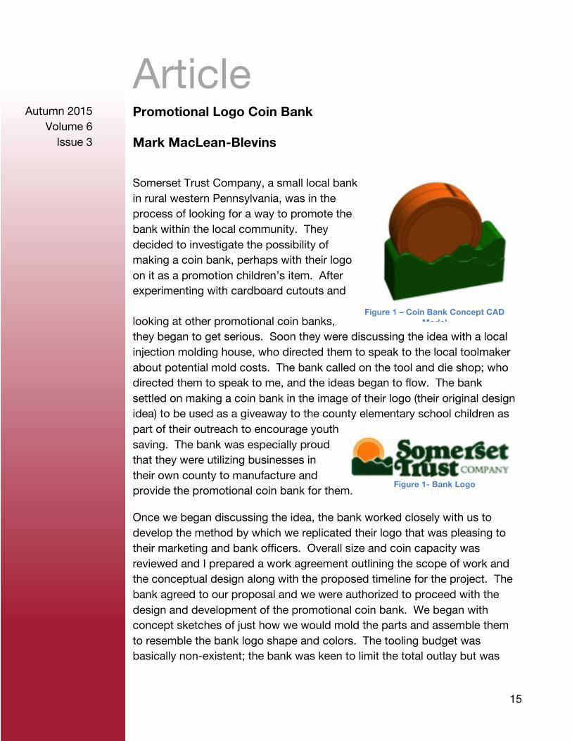
Somerset Trust Company, a small local bank in rural western Pennsylvania, was in the process of looking for a way to promote the bank within the local community. They decided to investigate the possibility of making a coin bank, perhaps with their logo on it as a promotion children’s item. After experimenting with cardboard cutouts and
looking at other promotional coin banks, they began to get serious. Soon they were discussing the idea with a local injection molding house, who directed them to speak to the local toolmaker about potential mold costs. The bank called on the tool and die shop; who directed them to speak to me, and the ideas began to flow. The bank settled on making a coin bank in the image of their logo (their original design idea) to be used as a giveaway to the county elementary school children as part of their outreach to encourage youth saving. The bank was especially proud that they were utilizing businesses in their own county to manufacture and provide the promotional coin bank for them.
Once we began discussing the idea, the bank worked closely with us to develop the method by which we replicated their logo that was pleasing to their marketing and bank officers. Overall size and coin capacity was reviewed and I prepared a work agreement outlining the scope of work and the conceptual design along with the proposed timeline for the project. The bank agreed to our proposal and we were authorized to proceed with the design and development of the promotional coin bank. We began with concept sketches of just how we would mold the parts and assemble them to resemble the bank logo shape and colors. The tooling budget was basically non-existent; the bank was keen to limit the total outlay but was
Figure 1 – Coin Bank Concept CAD Model
Figure 1- Bank Logo
16
Autumn 2015 Volume 6
Issue 3
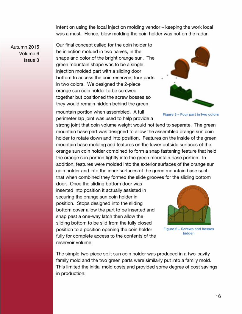
intent on using the local injection molding vendor – keeping the work local was a must. Hence, blow molding the coin holder was not on the radar.
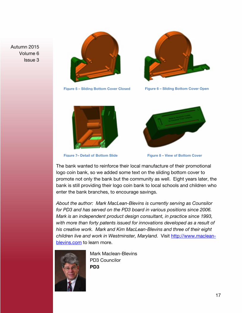
Our final concept called for the coin holder to be injection molded in two halves, in the shape and color of the bright orange sun. The green mountain shape was to be a single injection molded part with a sliding door bottom to access the coin reservoir; four parts in two colors. We designed the 2-piece orange sun coin holder to be screwed together but positioned the screw bosses so they would remain hidden behind the green mountain portion when assembled. A full perimeter lap joint was used to help provide a strong joint that coin volume weight would not tend to separate. The green mountain base part was designed to allow the assembled orange sun coin holder to rotate down and into position. Features on the inside of the green mountain base molding and features on the lower outside surfaces of the orange sun coin holder combined to form a snap fastening feature that held the orange sun portion tightly into the green mountain base portion. In addition, features were molded into the exterior surfaces of the orange sun coin holder and into the inner surfaces of the green mountain base such that when combined they formed the slide grooves for the sliding bottom door. Once the sliding bottom door was inserted into position it actually assisted in securing the orange sun coin holder in position. Stops designed into the sliding bottom cover allow the part to be inserted and snap past a one-way latch then allow the sliding bottom to be slid from the fully closed position to a position opening the coin holder fully for complete access to the contents of the reservoir volume.
The simple two-piece split sun coin holder was produced in a two-cavity family mold and the two green parts were similarly put into a family mold. This limited the initial mold costs and provided some degree of cost savings in production.
Figure 3 – Four part in two colors
Figure 2 – Screws and bosses hidden
17
Autumn 2015 Volume 6
Issue 3
The bank wanted to reinforce their local manufacture of their promotional logo coin bank, so we added some text on the sliding bottom cover to promote not only the bank but the community as well. Eight years later, the bank is still providing their logo coin bank to local schools and children who enter the bank branches, to encourage savings.
About the author: Mark MacLean-Blevins is currently serving as Counsilor for PD3 and has served on the PD3 board in various positions since 2006. Mark is an independent product design consultant, in practice since 1993, with more than forty patents issued for innovations developed as a result of his creative work. Mark and Kim MacLean-Blevins and three of their eight children live and work in Westminster, Maryland. Visit http://www.maclean-blevins.com to learn more.
Mark Maclean-Blevins PD3 Councilor PD3
Figure 7– Detail of Bottom Slide Figure 8 – View of Bottom Cover
Figure 5 – Sliding Bottom Cover Closed Figure 6 – Sliding Bottom Cover Open
18
Autumn 2015 Volume 6
Issue 3
Article Designers’ Corner, Rotational Molding, Part 14 Glenn L. Beall
ROTATIONALLY MOLDED HOLES -- PART 1 -- TYPES
Editor's Note: This is the 14th in an ongoing series of articles on design guidelines for rotationally molded parts. These articles are written by Glenn Beall, a Past Chairman and one of the Founders of SPE's Rotational Molding Division. He has been designing rotational molded parts since 1963.
The ability to provide holes into and through the wall of a part is an important attribute of any plastics molding process.
During the heating portion of the rotational molding process, the plastic material coats all hot surfaces on the cavity that it comes in contact with. One advantage of this process is that the molded parts do not contain the weld-lines at holes that weaken parts produced by the melt-flow processes such as injection and compression molding.
Rotational molding is not ideal for producing parts with holes through the wall. This is a handicap that the process shares with thermoforming and blow molding. In spite of this limitation, molders and tool makers have succeeded in developing techniques for molding holes through, into, and onto rotationally molded parts. Every conceivable size and shape of hole and recess has been molded, but round holes are the most common.
Holes that project into a molded part, as shown in Figure 1, are the easiest to produce. They are formed when the plastic coats inward projecting core pins.
19
Autumn 2015 Volume 6
Issue 3
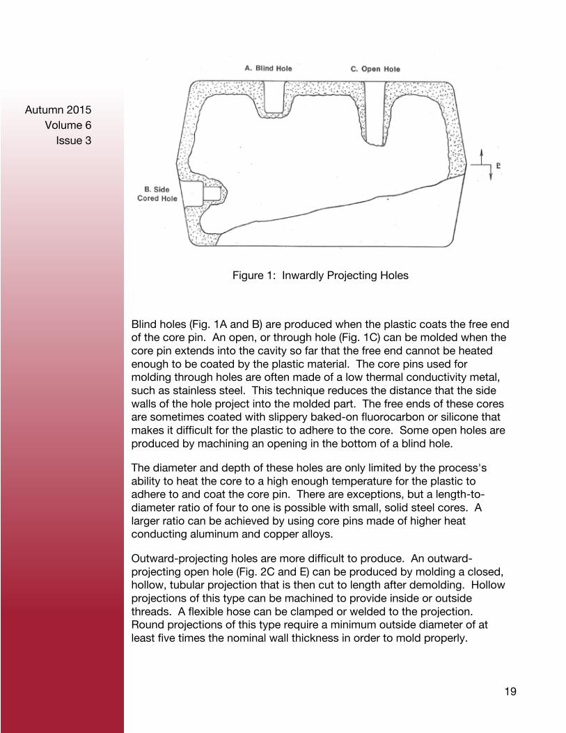
Figure 1: Inwardly Projecting Holes
Blind holes (Fig. 1A and B) are produced when the plastic coats the free end of the core pin. An open, or through hole (Fig. 1C) can be molded when the core pin extends into the cavity so far that the free end cannot be heated enough to be coated by the plastic material. The core pins used for molding through holes are often made of a low thermal conductivity metal, such as stainless steel. This technique reduces the distance that the side walls of the hole project into the molded part. The free ends of these cores are sometimes coated with slippery baked-on fluorocarbon or silicone that makes it difficult for the plastic to adhere to the core. Some open holes are produced by machining an opening in the bottom of a blind hole.
The diameter and depth of these holes are only limited by the process's ability to heat the core to a high enough temperature for the plastic to adhere to and coat the core pin. There are exceptions, but a length-to-diameter ratio of four to one is possible with small, solid steel cores. A larger ratio can be achieved by using core pins made of higher heat conducting aluminum and copper alloys.
Outward-projecting holes are more difficult to produce. An outward-projecting open hole (Fig. 2C and E) can be produced by molding a closed, hollow, tubular projection that is then cut to length after demolding. Hollow projections of this type can be machined to provide inside or outside threads. A flexible hose can be clamped or welded to the projection. Round projections of this type require a minimum outside diameter of at least five times the nominal wall thickness in order to mold properly.
20
Autumn 2015 Volume 6
Issue 3
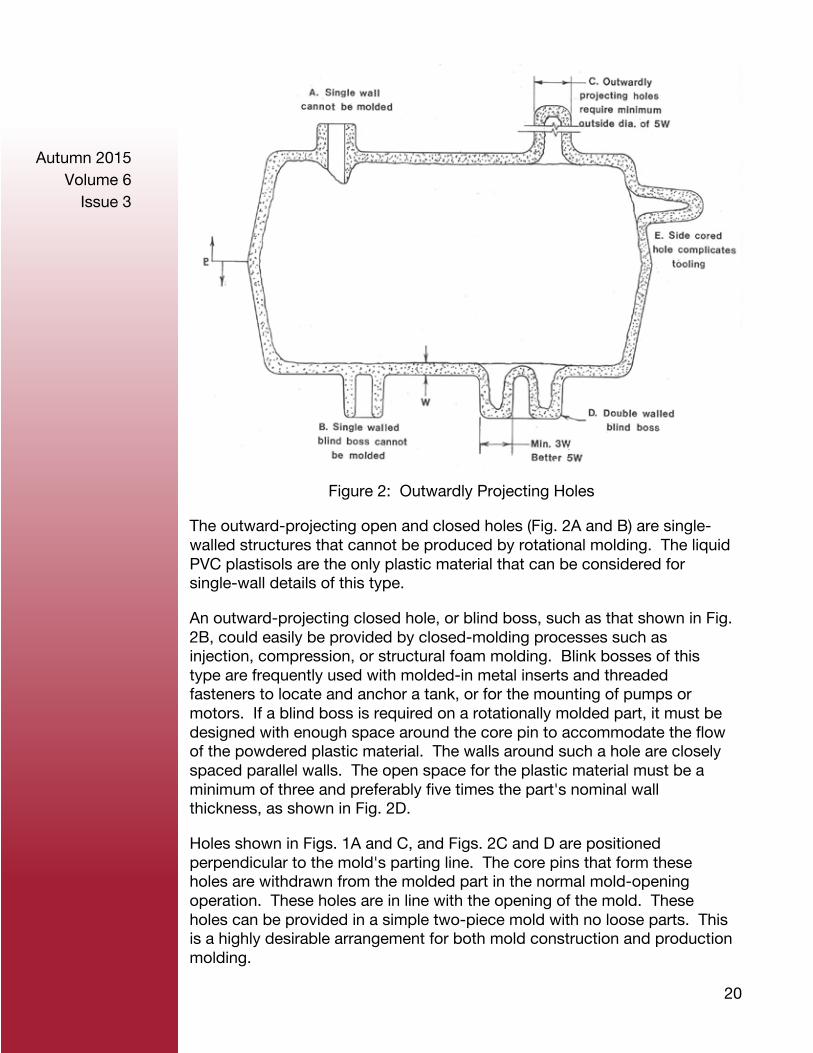
Figure 2: Outwardly Projecting Holes
The outward-projecting open and closed holes (Fig. 2A and B) are single-walled structures that cannot be produced by rotational molding. The liquid PVC plastisols are the only plastic material that can be considered for single-wall details of this type.
An outward-projecting closed hole, or blind boss, such as that shown in Fig. 2B, could easily be provided by closed-molding processes such as injection, compression, or structural foam molding. Blink bosses of this type are frequently used with molded-in metal inserts and threaded fasteners to locate and anchor a tank, or for the mounting of pumps or motors. If a blind boss is required on a rotationally molded part, it must be designed with enough space around the core pin to accommodate the flow of the powdered plastic material. The walls around such a hole are closely spaced parallel walls. The open space for the plastic material must be a minimum of three and preferably five times the part's nominal wall thickness, as shown in Fig. 2D.
Holes shown in Figs. 1A and C, and Figs. 2C and D are positioned perpendicular to the mold's parting line. The core pins that form these holes are withdrawn from the molded part in the normal mold-opening operation. These holes are in line with the opening of the mold. These holes can be provided in a simple two-piece mold with no loose parts. This is a highly desirable arrangement for both mold construction and production molding.

21
Autumn 2015 Volume 6
Issue 3
The important topic of hole location will be discussed in the next Designers' Corner article.
This article is a condensed extract from G. L. Beall’s Hanser Publishers book entitled “Rotational Molding Design, Materials, Tooling, & Processing” available at [email protected]. Hanser Gardner Publications, (877) 751-5051.
Glenn L. Beall PD3 Board Member PD3
22
Autumn 2015 Volume 6
Issue 3
Article Engineers can’t (and shouldn’t) do everything
Gordon Grob
Too often the signature, defining trait that distinguishes the engineer from the masses is a relentless self-autonomous drive to repair, fix, tweak, and file everything entirely under their own power, never yielding even a minute measure of control to anyone. It’s a vast mystery where exactly the engineer derives this fierce bend towards complete autonomy.
You could argue that it’s an intrinsic function of brain wiring, or that it’s a direct result of rewarding time spent during the engineer’s younger, more formative years studying, designing, and fixing complex mechanical and electrical systems. Nevertheless, one thing is for certain – this attitude permeates every aspect of many engineer’s lives.
Even for the most competent engineer that’s able to fix a leak in a high-pressure power steering line before their morning cup of coffee, there are still legitimate, calculated reasons to call in an expert. Unfortunately, all too often the cold, calculating brain of engineers boils many situations down to only the hard dollars and cents that could be saved by performing a job on their own. But this is an incomplete calculation that neglects many other factors.
There are a few broad considerations that are applicable across an extensive range of real world situations, from tax preparation to basement remodeling, that the zealous “Do-It-Yourself” (DIY) engineer must meticulously deploy in order to master sometimes overwhelming tendencies to go it alone.
Know your limits
The risks of failure must be the paramount concern of the DIY engineer and must be carefully considered at the very beginning of the project. This includes the safety concerns as well as other non-safety related risks associated with completing a more mundane project. Everyone has a story of a home-repair injury or near miss injury that could have easily been
23
Autumn 2015 Volume 6
Issue 3
avoided by an expert with a better handle on the job.
There is also significant risk involved with not completely understanding intricate complexities of the project’s mechanical or electrical nature from a functional standpoint. It’s far too easy to turn a project into a complete tire fire, as the engineer languishes over an exposed automobile engine block as part of a botched head gasket replacement job. There’s a big difference between watching a how-to video and actually successfully completing the work. The would-be DIY engineers confuse the two at their own risk.
The hazards associated with something such as a mistakenly filed self-prepared tax return probably will not involve immediate physical bodily harm (hopefully). However, an audit from the IRS at the very least will cause serious headache and hassle (which could have very easily been avoided by the consultation of a professional tax filing agency). A sober assessment of all these risk factors is critical in deciding whether a project should be taken on alone.
Find trusted professionals
In order for a DIY engineer to realistically consider handing off a task to a professional, peace of mind about the transfer is absolutely essential. It is especially important for the engineer to develop personal and professional relationships with trusted car mechanics, general contractors, plumbers, and accountants. These sorts of relationships will foster something more along the lines of a partnership and will help the engineer to trust that the job will be completed satisfactorily while the engineer maintains a level of involvement at every step along the way.
With these sorts of professional contacts at the ready with the tap of a smartphone screen, the engineer can feel far more confident handing off important work to fully capable and competent professionals that also understand the self-start nature of the engineer and will keep the engineer in the loop every step along the way, detailing exactly what work they will be performing, along with the cost and details. The peace of mind afforded to the engineer in this way is absolutely priceless.
It’s up to the engineer to find and grow these sorts of professional relationships.
24
Autumn 2015 Volume 6
Issue 3
Remember that time is money
In performing the assessment of whether or not a project/job should be done, it’s very important to remember that the engineer’s time is very valuable and time is quite literally money. For this reason, it’s essential that at least a cursory assessment of the costs of outsourcing to a professional compared with the opportunity costs associated with utilizing the tangible value of the engineer’s time in order to perform the job.
Certainly there could be an endless number of monetary factors to consider, such as the increased time and cost associated with learning to do the job yourself. There is also an abundance of other non-monetary personal, family, and societal demands placed on every red-blooded adult that make the engineer’s time even that much more valuable.
Although it’s impossible to precisely gauge the exact value of free time, a decent place to start is the hourly wage associated with a full time job plus the rough opportunity costs associated with all the factors discussed above. If it’s possible to pay a professional at or below the approximate value of the engineer’s time, outsourcing the job to someone else is a no brainer move.
In conclusion
All of this discussion is not to underplay the benefits of being a self-starter or possessing a wide range of skills; certainly there are real, tangible benefits to spearheading certain jobs, rather than paying someone to do comparable work. Rather than completely suppress the impulse to be a DIY engineer, it’s far better to simply take time out to remember the principles outlined above before undertaking a job in order to evaluate the benefits of deferring to an expert.

25
Autumn 2015 Volume 6
Issue 3
Gordon is a twenty-something mechanical engineer with an advanced degree in materials science. He is a product of the Rustbelt, currently residing in Pittsburgh after growing up near Cleveland. In his spare time, when he’s not searching for an exotic coffee or espresso drink, you can find him participating in an endurance sport, such as running or cycling.
Originally published 28 October 2015 on the GrabCAD blog, http://blog.grabcad.com/.
Gordon Grob GrabCAD PD3
26
Autumn 2015 Volume 6
Issue 3
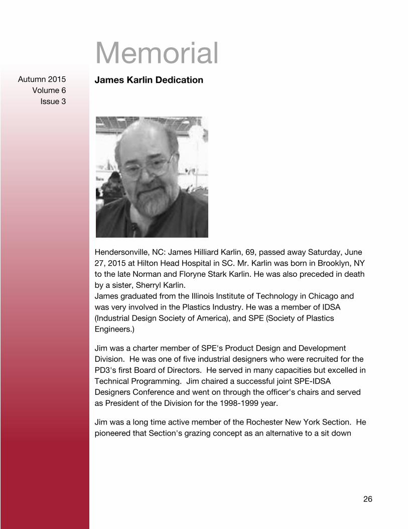
Memorial James Karlin Dedication
Hendersonville, NC: James Hilliard Karlin, 69, passed away Saturday, June 27, 2015 at Hilton Head Hospital in SC. Mr. Karlin was born in Brooklyn, NY to the late Norman and Floryne Stark Karlin. He was also preceded in death by a sister, Sherryl Karlin. James graduated from the Illinois Institute of Technology in Chicago and was very involved in the Plastics Industry. He was a member of IDSA (Industrial Design Society of America), and SPE (Society of Plastics Engineers.)
Jim was a charter member of SPE's Product Design and Development Division. He was one of five industrial designers who were recruited for the PD3's first Board of Directors. He served in many capacities but excelled in Technical Programming. Jim chaired a successful joint SPE-IDSA Designers Conference and went on through the officer's chairs and served as President of the Division for the 1998-1999 year.
Jim was a long time active member of the Rochester New York Section. He pioneered that Section's grazing concept as an alternative to a sit down
27
Autumn 2015 Volume 6
Issue 3
dinner at the Section's Annual Suppliers Night.
He was a loving father and grandfather and will be deeply missed. He is survived by his wife, Deborah Karlin; two sons, Jeremy Karlin and Daniel Karlin; a brother, Barry Karlin and one grandson, Elijah Karlin. No services are planned and Groce Funeral Home at Lake Julian in Arden, NC is assisting the family with a guest register available online at grocefuneralhome.com.
Funeral Home
Groce Funeral Home & Cremation Service 72 Long Shoals Rd Arden, NC 28704 (828) 687-3530
Published in Rochester Democrat And Chronicle on July 1, 2015
28
Autumn 2015 Volume 6
Issue 3
Announcements PD3 Calendar
December 8-9, 2015
CYCLITECH Conference 2015
Brussels, Belgium Carine Roos, Email: [email protected]
January 10-12, 2016
ANTEC® Dubai in partnership with GPCA PlastiCon 2016
Dubai, UAE Chair: Dr. Raed Al-Zu’bi, Email: [email protected]
January 12, 2016
Patent Law Fundimentals
TBD
February 21-24, 2016
2016 SPE International Polyolefins Conference
Houston, Texas Chair: Chuck Crosby, Email: [email protected]
March 10, 2016
10th European “Thermoforming” Conference 2016
TBD
March 22-24, 2016
2016 Shanghai TPO Conference
Shanghai, China Chair: Sassan Tarahomi, Email: [email protected]
29
Autumn 2015 Volume 6
Issue 3
March 29-31, 2016
SPE Shape Extrusion Topcon
Gurnee, Illinois Chair: Matt Bennett
April 16-20, 2016
Thermoset 2016
Cleveland, Ohio Chair: Len Nunnery, Email: [email protected]
April 19-21, 2016
Bioplastics Materials Topcon and Tutorial 2016
Minneapolis, Minnesota Chair: Edwin Tam, Email: [email protected]
April 25-27, 2015
Re|focus Recycling Summit & Expo
Orlando, Florida
May 23-25, 2016
ANTEC
JW Marriott Indianapolis, 10 S. West Street, Indianapolis, Indiana, USA
1 (317) 860-5800 or 1 (800) 228-9290
30
Autumn 2015 Volume 6
Issue 3
Boardroom 2014-2015 Board of Directors Chairperson Al McGovern [email protected]
Vice Chairperson
Chairperson Elect Edward Probst [email protected]
Secretary David Tucker [email protected]
Treasurer Larry Schneider [email protected]
Membership Jeremy Braaten [email protected]
Councilor Mark MacLean-Blevins [email protected]
Past Chairperson Michael Paloian [email protected]
Past Treasurer Longtime Contributor Mark Wolverton
Director Glenn Beall [email protected]
Director Lance Neward [email protected]
Director Ken Pawlak [email protected]
Contributor Eric R. Larson, PE [email protected]