Embed Size (px)
Citation preview
L
Manual
Global Drive
IEC 61131-3 programming
Drive PLC Developer StudioIntroduction to
Global DrivePLC Developer Studio

Important note:
The software is supplied to the user as described in this document. Any risks resulting from its quality or use remain the responsibilityof the user. The user must provide all safety measures protecting against possible maloperation.
We do not take any liability for direct or indirect damage, e.g. profit loss, order loss or any loss regarding business.
� 2003 Lenze Drive Systems GmbH
No part of this documentation may be copied or made available to third parties without the explicit written approval of Lenze DriveSystems GmbH.
All information given in this online documentation hasbeencarefully selectedand tested for compliancewith thehardware andsoftwaredescribed. Nevertheless, discrepancies cannot be ruled out. We do not accept any responsibility or liability for any damage that mayoccur. Required corrections will be included in updates of this documentation.
All product names mentioned in this documentation are trademarks of the corresponding owners.
Version 2.0 09/2003
Introduction to IEC 61131-3 programmingContents
1l DDS-IEC61131 EN 2.0
1 Preface and general information 2. . . . . . . . . . . . . . . . . . . . . . . . . . . . . . . . . . . . . . . . . . .
1.1 For further information on IEC 61131-3 programming 2. . . . . . . . . . . . . . . . . . . . . . . . . . . . . . . . . . . . . .
2 The software model 3. . . . . . . . . . . . . . . . . . . . . . . . . . . . . . . . . . . . . . . . . . . . . . . . . . . . .
2.1 Resources within a configuration 3. . . . . . . . . . . . . . . . . . . . . . . . . . . . . . . . . . . . . . . . . . . . . . . . . . . . .2.1.1 Tasks 3. . . . . . . . . . . . . . . . . . . . . . . . . . . . . . . . . . . . . . . . . . . . . . . . . . . . . . . . . . . . . . . . . .
2.2 Program Organization Units, POUs 4. . . . . . . . . . . . . . . . . . . . . . . . . . . . . . . . . . . . . . . . . . . . . . . . . . . . .2.2.1 Programs 4. . . . . . . . . . . . . . . . . . . . . . . . . . . . . . . . . . . . . . . . . . . . . . . . . . . . . . . . . . . . . . .2.2.2 Function blocks 5. . . . . . . . . . . . . . . . . . . . . . . . . . . . . . . . . . . . . . . . . . . . . . . . . . . . . . . . . . .2.2.3 Functions 6. . . . . . . . . . . . . . . . . . . . . . . . . . . . . . . . . . . . . . . . . . . . . . . . . . . . . . . . . . . . . . .
2.3 Control restart 7. . . . . . . . . . . . . . . . . . . . . . . . . . . . . . . . . . . . . . . . . . . . . . . . . . . . . . . . . . . . . . . . . . .
3 The communication model 8. . . . . . . . . . . . . . . . . . . . . . . . . . . . . . . . . . . . . . . . . . . . . . .
3.1 Access paths 8. . . . . . . . . . . . . . . . . . . . . . . . . . . . . . . . . . . . . . . . . . . . . . . . . . . . . . . . . . . . . . . . . . . .
3.2 Global variables 8. . . . . . . . . . . . . . . . . . . . . . . . . . . . . . . . . . . . . . . . . . . . . . . . . . . . . . . . . . . . . . . . . .
3.3 Call parameters 8. . . . . . . . . . . . . . . . . . . . . . . . . . . . . . . . . . . . . . . . . . . . . . . . . . . . . . . . . . . . . . . . . .
3.4 Communication organization units 8. . . . . . . . . . . . . . . . . . . . . . . . . . . . . . . . . . . . . . . . . . . . . . . . . . . .
4 General language elements 9. . . . . . . . . . . . . . . . . . . . . . . . . . . . . . . . . . . . . . . . . . . . . . .
4.1 Identifiers 9. . . . . . . . . . . . . . . . . . . . . . . . . . . . . . . . . . . . . . . . . . . . . . . . . . . . . . . . . . . . . . . . . . . . . .
4.2 Keywords 9. . . . . . . . . . . . . . . . . . . . . . . . . . . . . . . . . . . . . . . . . . . . . . . . . . . . . . . . . . . . . . . . . . . . . .
4.3 Comments 9. . . . . . . . . . . . . . . . . . . . . . . . . . . . . . . . . . . . . . . . . . . . . . . . . . . . . . . . . . . . . . . . . . . . . .
4.4 Literals 9. . . . . . . . . . . . . . . . . . . . . . . . . . . . . . . . . . . . . . . . . . . . . . . . . . . . . . . . . . . . . . . . . . . . . . . .
4.5 Data types 10. . . . . . . . . . . . . . . . . . . . . . . . . . . . . . . . . . . . . . . . . . . . . . . . . . . . . . . . . . . . . . . . . . . . . .
4.6 Variables 11. . . . . . . . . . . . . . . . . . . . . . . . . . . . . . . . . . . . . . . . . . . . . . . . . . . . . . . . . . . . . . . . . . . . . . .
5 Programming languages 12. . . . . . . . . . . . . . . . . . . . . . . . . . . . . . . . . . . . . . . . . . . . . . . . .
5.1 Instruction List (IL) 12. . . . . . . . . . . . . . . . . . . . . . . . . . . . . . . . . . . . . . . . . . . . . . . . . . . . . . . . . . . . . . . .
5.2 Structured Text (ST) 13. . . . . . . . . . . . . . . . . . . . . . . . . . . . . . . . . . . . . . . . . . . . . . . . . . . . . . . . . . . . . . .
5.3 Sequential Function Chart (SFC) 14. . . . . . . . . . . . . . . . . . . . . . . . . . . . . . . . . . . . . . . . . . . . . . . . . . . . . .
5.4 Function Block Diagram (FBD) 16. . . . . . . . . . . . . . . . . . . . . . . . . . . . . . . . . . . . . . . . . . . . . . . . . . . . . . .
5.5 Ladder Diagram (LD) 16. . . . . . . . . . . . . . . . . . . . . . . . . . . . . . . . . . . . . . . . . . . . . . . . . . . . . . . . . . . . . .
6 Appendix 18. . . . . . . . . . . . . . . . . . . . . . . . . . . . . . . . . . . . . . . . . . . . . . . . . . . . . . . . . . . . .
6.1 IEC keywords 18. . . . . . . . . . . . . . . . . . . . . . . . . . . . . . . . . . . . . . . . . . . . . . . . . . . . . . . . . . . . . . . . . . . .
6.2 Conventions for Lenze variable identifiers 20. . . . . . . . . . . . . . . . . . . . . . . . . . . . . . . . . . . . . . . . . . . . . . .6.2.1 System block designation 20. . . . . . . . . . . . . . . . . . . . . . . . . . . . . . . . . . . . . . . . . . . . . . . . . . .6.2.2 Indication of the variable type 21. . . . . . . . . . . . . . . . . . . . . . . . . . . . . . . . . . . . . . . . . . . . . . . .6.2.3 Indication of the data type 21. . . . . . . . . . . . . . . . . . . . . . . . . . . . . . . . . . . . . . . . . . . . . . . . . . .6.2.4 Identifier 22. . . . . . . . . . . . . . . . . . . . . . . . . . . . . . . . . . . . . . . . . . . . . . . . . . . . . . . . . . . . . . . .6.2.5 Indication of the signal type 22. . . . . . . . . . . . . . . . . . . . . . . . . . . . . . . . . . . . . . . . . . . . . . . . . .6.2.6 Examples of variable identifiers 22. . . . . . . . . . . . . . . . . . . . . . . . . . . . . . . . . . . . . . . . . . . . . . .
6.3 Glossary 23. . . . . . . . . . . . . . . . . . . . . . . . . . . . . . . . . . . . . . . . . . . . . . . . . . . . . . . . . . . . . . . . . . . . . . .
Introduction to IEC 61131-3 programmingPreface and general information
2 lDDS-IEC61131 EN 2.0
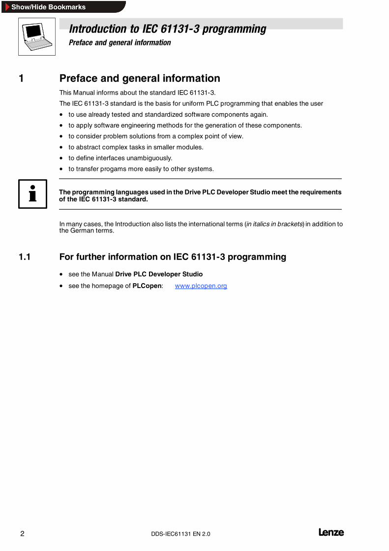
1 Preface and general informationThis Manual informs about the standard IEC 61131-3.
The IEC 61131-3 standard is the basis for uniform PLC programming that enables the user
• to use already tested and standardized software components again.
• to apply software engineering methods for the generation of these components.
• to consider problem solutions from a complex point of view.
• to abstract complex tasks in smaller modules.
• to define interfaces unambiguously.
• to transfer progams more easily to other systems.
The programming languages used in the Drive PLC Developer Studio meet the requirementsof the IEC 61131-3 standard.
In many cases, the Introduction also lists the international terms (in italics in brackets) in addition tothe German terms.
1.1 For further information on IEC 61131-3 programming
• see the Manual Drive PLC Developer Studio
• see the homepage of PLCopen: www.plcopen.org
Introduction to IEC 61131-3 programmingThe software model
3l DDS-IEC61131 EN 2.0
2 The software modelThe software model of IEC 61131-3 describes the concepts of configuration, resource, task,program, function block and function and their connection.
For the definition of these terms, the standard is based on a maximum powerful PLC providing thefollowing features:
• Mulit-processor can be used
• Multi-tasking is possible
• Unlimited number of analog and digital inputs and outputs
• Communication with other PLCs and PCs is possible
2.1 Resources within a configuration
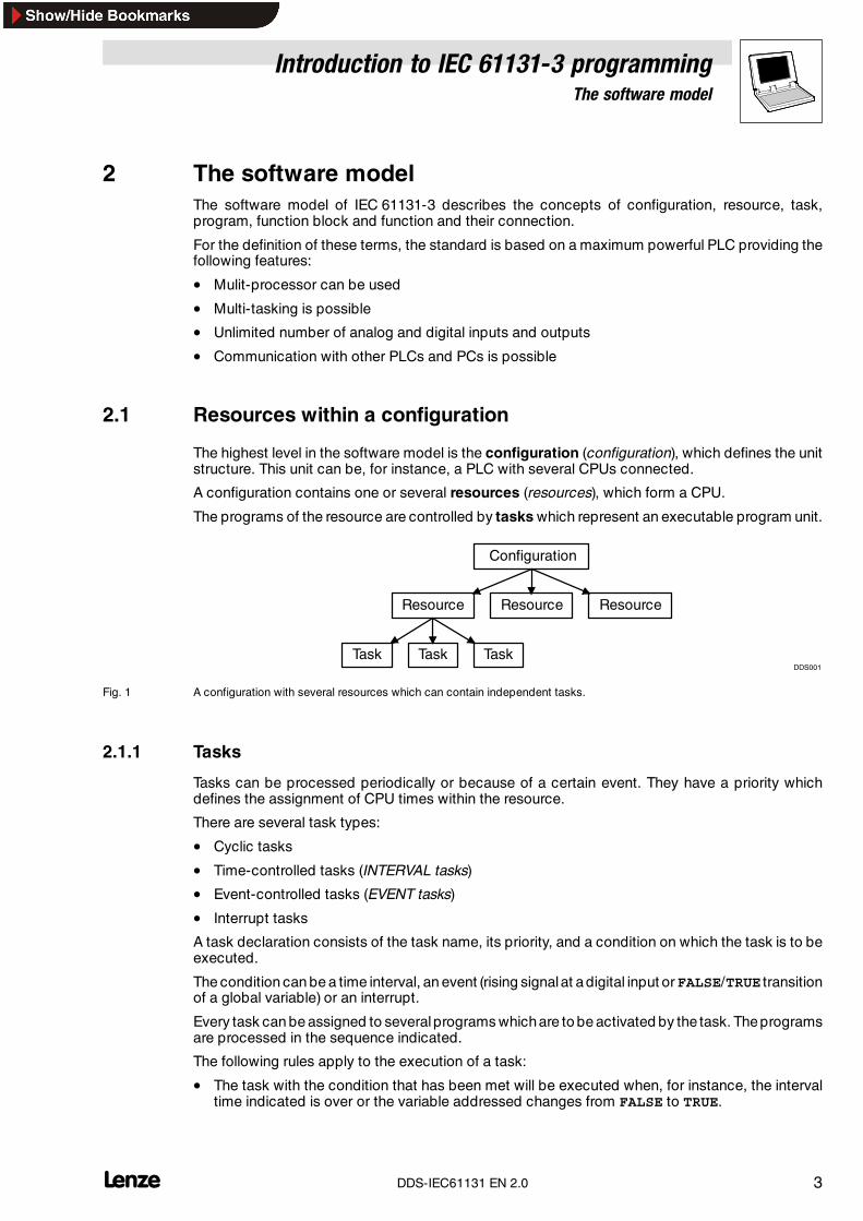
The highest level in the software model is the configuration (configuration), which defines the unitstructure. This unit can be, for instance, a PLC with several CPUs connected.
A configuration contains one or several resources (resources), which form a CPU.
The programs of the resource are controlled by tasks which represent an executable program unit.
Configuration
Resource
Task
Resource Resource
Task TaskDDS001
Fig. 1 A configuration with several resources which can contain independent tasks.
2.1.1 Tasks
Tasks can be processed periodically or because of a certain event. They have a priority whichdefines the assignment of CPU times within the resource.
There are several task types:
• Cyclic tasks
• Time-controlled tasks (INTERVAL tasks)
• Event-controlled tasks (EVENT tasks)
• Interrupt tasks
A task declaration consists of the task name, its priority, and a condition on which the task is to beexecuted.
The condition can be a time interval, an event (rising signalat adigital input orFALSE/TRUE transitionof a global variable) or an interrupt.
Every task can be assigned to severalprograms whichare to be activated by the task. Theprogramsare processed in the sequence indicated.
The following rules apply to the execution of a task:
• The task with the condition that has been met will be executed when, for instance, the intervaltime indicated is over or the variable addressed changes from FALSE to TRUE.
Introduction to IEC 61131-3 programmingThe software model
4 lDDS-IEC61131 EN 2.0
• If several tasks fulfill the condition, the task with the highest priority will be executed.
• It is not possible to assign the same priority to several tasks.(Exception: Priority 0 = Task inhibited)
• If a task with a higher priority meets the condition while another task is being processed, thetask with the lower prority will be interrupted and only be processed after the other task hasbeen completed.
2.2 Program Organization Units, POUs
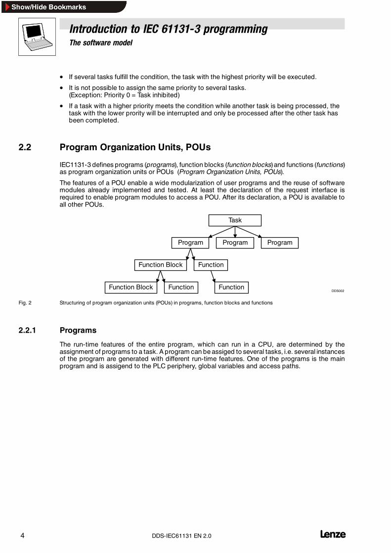
IEC1131-3 defines programs (programs), function blocks (function blocks)and functions (functions)as program organization units or POUs (Program Organization Units, POUs).
The features of a POU enable a wide modularization of user programs and the reuse of softwaremodules already implemented and tested. At least the declaration of the request interface isrequired to enable program modules to access a POU. After its declaration, a POU is available toall other POUs.
Task
Program
Function Block
Program Program
Function
Function Block Function FunctionDDS002
Fig. 2 Structuring of program organization units (POUs) in programs, function blocks and functions
2.2.1 Programs
The run-time features of the entire program, which can run in a CPU, are determined by theassignment of programs to a task. A program can be assiged to several tasks, i.e. several instancesof the program are generated with different run-time features. One of the programs is the mainprogram and is assigend to the PLC periphery, global variables and access paths.
Introduction to IEC 61131-3 programmingThe software model
5l DDS-IEC61131 EN 2.0
2.2.2 Function blocks
The IEC 61131-3 standard uses standard functions and function blocks to standardize typical PLCfunctions. This ”Standard library” is an important basis for uniform, manufacturer-independentprogramming of PLC systems.
Function blocks (FBs) can be compared with integrated circuits, which include a certain controlfunction. They are used to set inputs/outputs and internal variables. The status of a function blockrequest is saved from cycle to cycle. Only the input and output variables of the function can beaddressed by the request program. A function block can also be called by another function block.
Instancing of function blocks
IEC 61131-3 provides the instancing of function blocks. An instance is a structure which saves allinternal input and output variables when a function block is called.
A program which calls FB1 three times has three instances of FB1, one for each call. The programcan thus be evaluated precisely on request and without any side effects. Please observe that allinstances use the same program code, i.e. changes of the program code have the same effect onal three requests.
Software tools like the Drive PLC Developer Studio help instancing by means of an automaticdeclaration: An instance name is specified for an FB call. This name manages the data structure ofthe call.
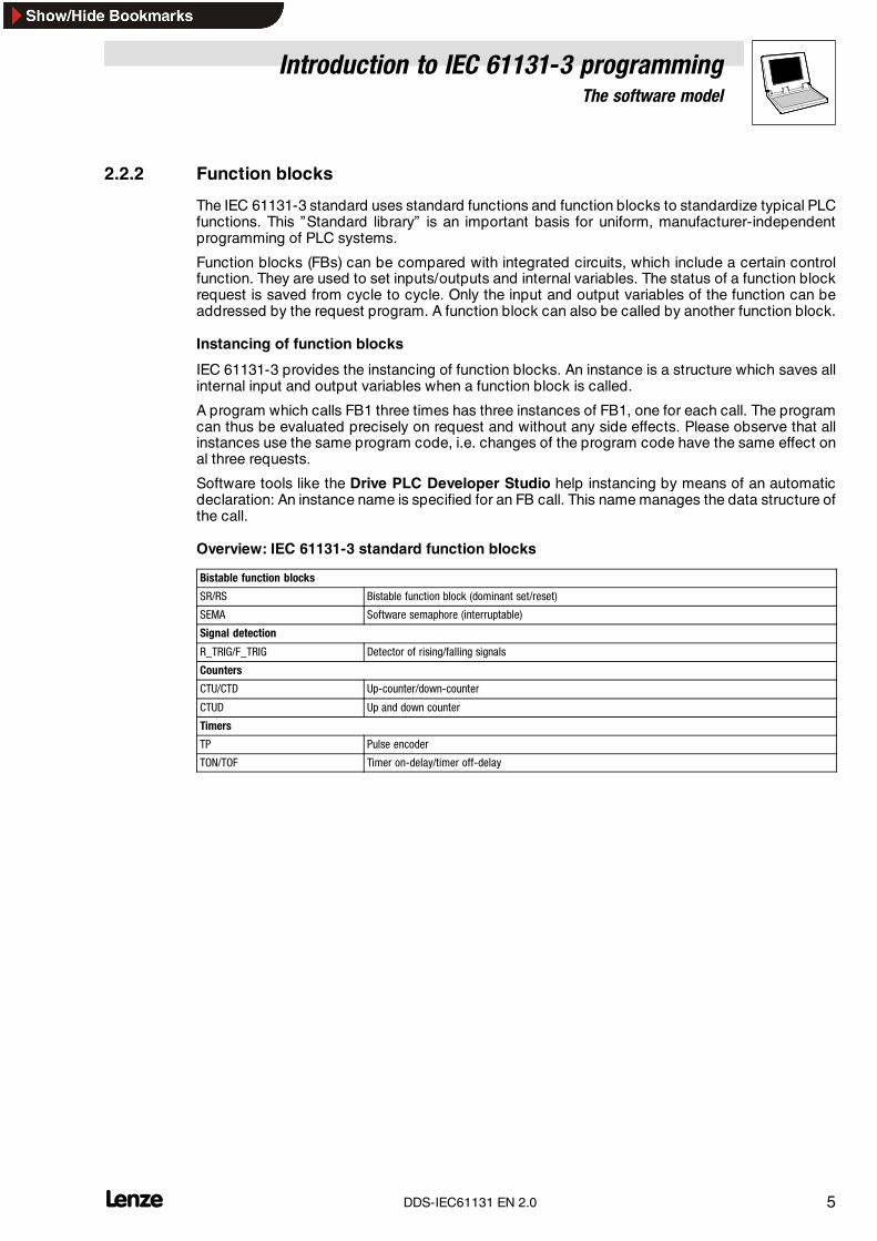
Overview: IEC 61131-3 standard function blocks
Bistable function blocks
SR/RS Bistable function block (dominant set/reset)
SEMA Software semaphore (interruptable)
Signal detection
R_TRIG/F_TRIG Detector of rising/falling signals
Counters
CTU/CTD Up-counter/down-counter
CTUD Up and down counter
Timers
TP Pulse encoder
TON/TOF Timer on-delay/timer off-delay
Introduction to IEC 61131-3 programmingThe software model
6 lDDS-IEC61131 EN 2.0
2.2.3 Functions
Unlike FBs, functions cannot buffer their internal values. Thus, they cannot use global variables,access function blocks and declare directly addressable variables. All functions have in commonthat they return the same output parameters if the input parameters are the same.
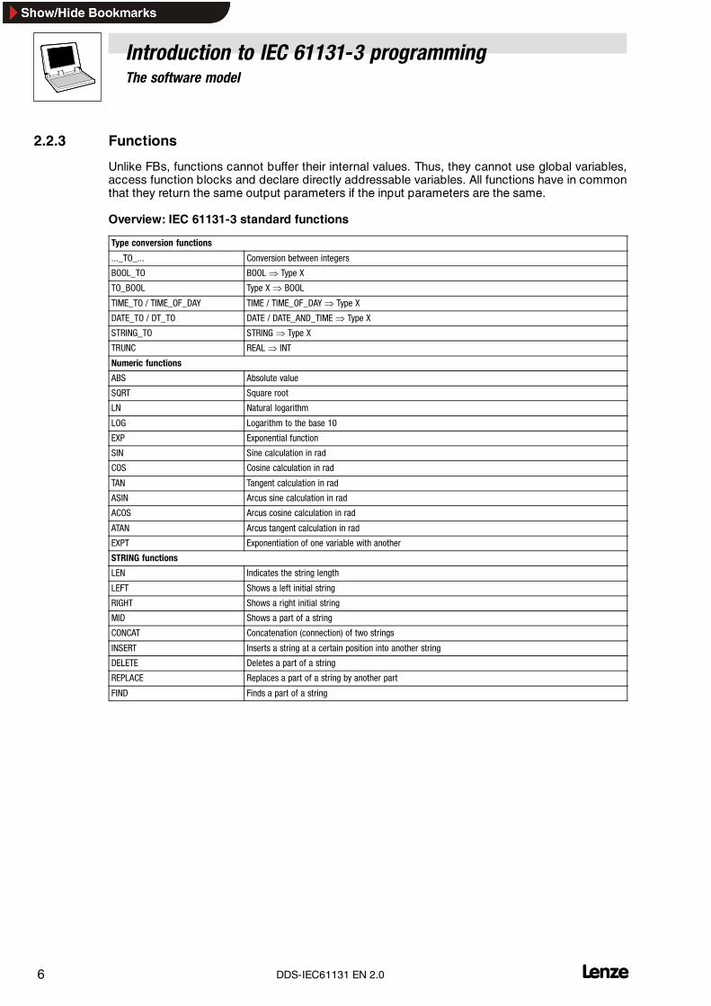
Overview: IEC 61131-3 standard functions
Type conversion functions
..._TO_... Conversion between integers
BOOL_TO BOOL � Type X
TO_BOOL Type X � BOOL
TIME_TO / TIME_OF_DAY TIME / TIME_OF_DAY � Type X
DATE_TO / DT_TO DATE / DATE_AND_TIME � Type X
STRING_TO STRING � Type X
TRUNC REAL � INT
Numeric functions
ABS Absolute value
SQRT Square root
LN Natural logarithm
LOG Logarithm to the base 10
EXP Exponential function
SIN Sine calculation in rad
COS Cosine calculation in rad
TAN Tangent calculation in rad
ASIN Arcus sine calculation in rad
ACOS Arcus cosine calculation in rad
ATAN Arcus tangent calculation in rad
EXPT Exponentiation of one variable with another
STRING functions
LEN Indicates the string length
LEFT Shows a left initial string
RIGHT Shows a right initial string
MID Shows a part of a string
CONCAT Concatenation (connection) of two strings
INSERT Inserts a string at a certain position into another string
DELETE Deletes a part of a string
REPLACE Replaces a part of a string by another part
FIND Finds a part of a string
Introduction to IEC 61131-3 programmingThe software model
7l DDS-IEC61131 EN 2.0
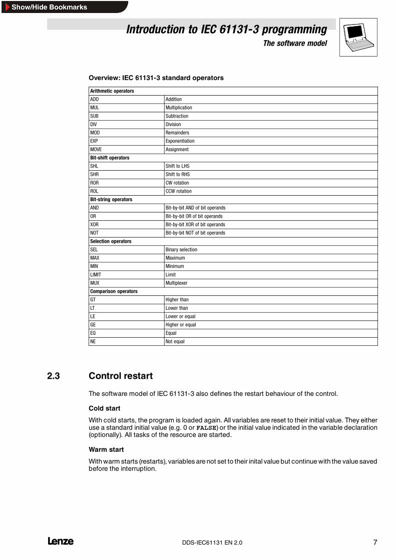
Overview: IEC 61131-3 standard operators
Arithmetic operators
ADD Addition
MUL Multiplication
SUB Subtraction
DIV Division
MOD Remainders
EXP Exponentiation
MOVE Assignment
Bit-shift operators
SHL Shift to LHS
SHR Shift to RHS
ROR CW rotation
ROL CCW rotation
Bit-string operators
AND Bit-by-bit AND of bit operands
OR Bit-by-bit OR of bit operands
XOR Bit-by-bit XOR of bit operands
NOT Bit-by-bit NOT of bit operands
Selection operators
SEL Binary selection
MAX Maximum
MIN Minimum
LIMIT Limit
MUX Multiplexer
Comparison operators
GT Higher than
LT Lower than
LE Lower or equal
GE Higher or equal
EQ Equal
NE Not equal
2.3 Control restart
The software model of IEC 61131-3 also defines the restart behaviour of the control.
Cold start
With cold starts, the program is loaded again. All variables are reset to their initial value. They eitheruse a standard initial value (e.g. 0 or FALSE) or the initial value indicated in the variable declaration(optionally). All tasks of the resource are started.
Warm start
With warm starts (restarts), variables are not set to their inital value but continue with the value savedbefore the interruption.
Introduction to IEC 61131-3 programmingThe communication model
8 lDDS-IEC61131 EN 2.0
3 The communication modelThe communication model of IEC 61131-3 describes the data exchange of configuration elementsby means of
• access paths
• global variables
• call parameters
• communication organization units (IEC 61131-5)
These unambiguously defined interfaces support the modularization and thus the reuseability ofprogram parts.
3.1 Access paths
Defined access paths enable the configuration elements to communicate with each other and PLCsystems.
3.2 Global variables
Global variables enable easy communication between programs. They can be declared and usedin a configuration, resource and program.
3.3 Call parameters
Within a program, data is exchanged by means of call parameters, i.e. input and output variables.Call parameters define interfaces for value transfers.
3.4 Communication organization units
Communication organization units provide communication services which are defined in part 5 ofIEC 61131 (in preparation).
Introduction to IEC 61131-3 programmingGeneral language elements
9l DDS-IEC61131 EN 2.0
4 General language elementsGeneral language elements of IEC 61131-3are identifiers, keywords, comments, literals, data typesand variables. They are described in detail in the following sub-sections:
4.1 Identifiers
Identifiers are used to address variables, functions, programs, etc. They are elements and cansupport the readability of programs.
• Identifiers are a sequence of letters, digits and underscores starting with a letter or anunderscore.
Identifiers must not
• include spaces and umlaute.
• be declared twice in the same way.
• be identical with keywords.(�Chapter 4.2)
Tip!The conventions used for the variable identifiers of Lenze system blocks, function blocks andfunctions are described in the appendix. (� 20)
4.2 Keywords
Keywords are unambiguous character combinations which are used as individual syntax elements.
• Keywords must not be used as identifiers.
Examples of keywords to IEC 61131-3
ABS, SIN, BOOL, FALSE, TRUE, FOR, NEXT, IF, THEN, VAR, GLOBAL, DATE, TIME, FUNCTION
4.3 Comments
Comments or program parts help to understand the program and are important communicationmeans. Comments are allowed in all text editors at any place and must start and end with a specialcharacter sequence (* and *). Every network can be commmented to document its functionality.
4.4 Literals
IEC 61131-3 describes literals as a sequence of characters, digits or times.
Character sequences
Character sequence literals have 0or morecharacters and start and end with inverted commas (e.g.’Character sequence’).
Digits
There are two different numerical literals: integers and reals.
Introduction to IEC 61131-3 programmingGeneral language elements
10 lDDS-IEC61131 EN 2.0
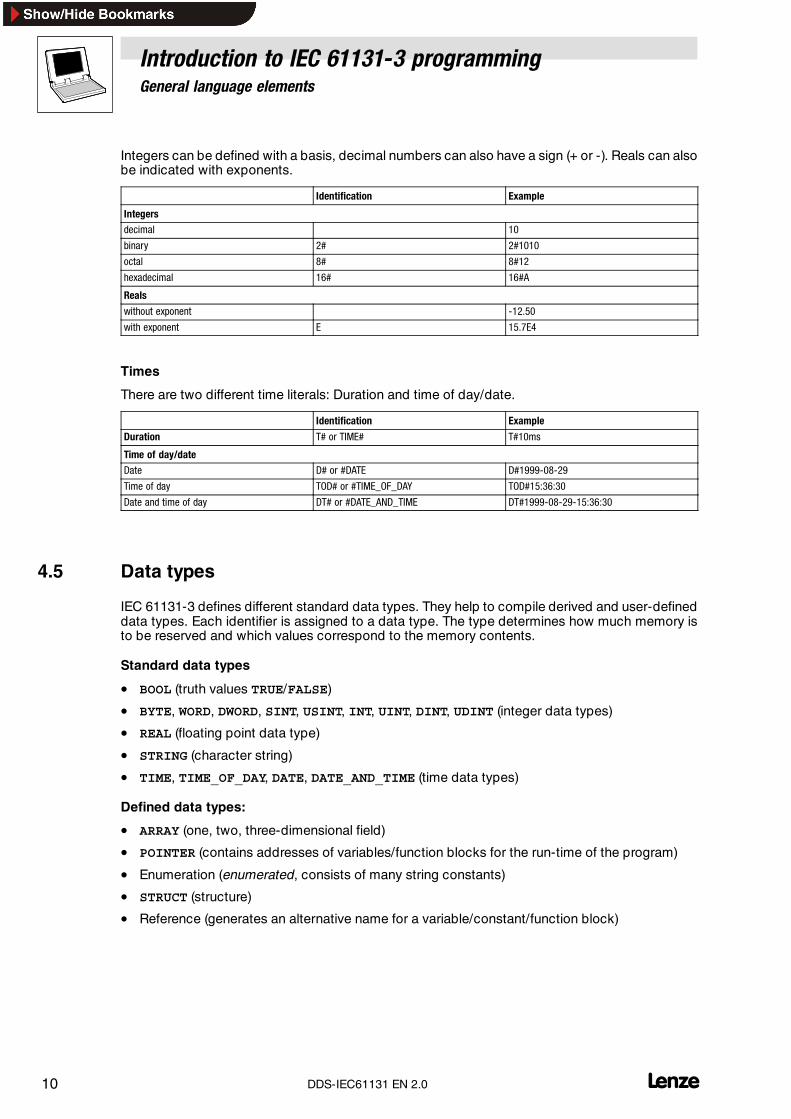
Integers can be defined with a basis, decimal numbers can also have a sign (+ or -). Reals can alsobe indicated with exponents.
Identification Example
Integers
decimal 10
binary 2# 2#1010
octal 8# 8#12
hexadecimal 16# 16#A
Reals
without exponent -12.50
with exponent E 15.7E4
Times
There are two different time literals: Duration and time of day/date.
Identification Example
Duration T# or TIME# T#10ms
Time of day/date
Date D# or #DATE D#1999-08-29
Time of day TOD# or #TIME_OF_DAY TOD#15:36:30
Date and time of day DT# or #DATE_AND_TIME DT#1999-08-29-15:36:30
4.5 Data types
IEC 61131-3 defines different standard data types. They help to compile derived and user-defineddata types. Each identifier is assigned to a data type. The type determines how much memory isto be reserved and which values correspond to the memory contents.
Standard data types
• BOOL (truth values TRUE/FALSE)
• BYTE, WORD, DWORD, SINT, USINT, INT, UINT, DINT, UDINT (integer data types)
• REAL (floating point data type)
• STRING (character string)
• TIME, TIME_OF_DAY, DATE, DATE_AND_TIME (time data types)
Defined data types:
• ARRAY (one, two, three-dimensional field)
• POINTER (contains addresses of variables/function blocks for the run-time of the program)
• Enumeration (enumerated, consists of many string constants)
• STRUCT (structure)
• Reference (generates an alternative name for a variable/constant/function block)
Introduction to IEC 61131-3 programmingGeneral language elements
11l DDS-IEC61131 EN 2.0
4.6 Variables
IEC 61131-3 defines five different variable classes:
• Global variables
• Local variables
• Input variables
• Output variables
• Input and output variables
Local variables do not have a connection to the outside, i.e. they can only be addressed from withina program part; global variables can be addressed from all POUs.
Input, output and input/output variables are related to a program, function or function block. Theycan be changed by reading and writing within the assigned POU; outside the POU, the change mustbe defined (input, output and input/output).
The variables are declared between the keywords VAR and END_VAR in the source text. In general,every variable is initialized after a cold restart. Thedefault value is usually 0 orFALSE. Auser-specificinitialization with another value is possible with the sign ” :=” in the declaration.
Variable attributes
The following attributes can be used additionally when declaring a variable:
• RETAIN: These variables remain the same even after a power failure. The program continueswith the values saved when being restarted.
• CONSTANT: Variable values cannot be changed.
• AT: Variables have a fixed location in the memory map (fixed address).
Example: Declaration of an output variable with initialization value
VAR_OUTPUTpar_out1 : INT := 10; (* Output parameter 1 with start value 10
*)END_VAR
Fixedly addressed variables
Variables can be assigned to a physical memory location (PLC) by means of the keyword AT whenbeing declared.
The address is indicated as a special character sequence. The character sequence starts with apercentage sign ”% ” followed by a range prefix and a prefix (data type) for size and ends with a digitsequence which indicates the memory location.
Range prefixes: I (Input), Q(Output), M(Marker, internal memory range)
Size prefix: X (Single bit), B(Byte, 8 bits), W(Word, 16 bits), D(Double word, 32 bits)
Examples: %QX1.0.2 Output bit 2%IW1.0.1 Input bit 1%MB7 Marker byte 7%MW1 Marker word 1%MD3 Marker double word 3%MX1.2 Third marker bit in marker word 1
Introduction to IEC 61131-3 programmingProgramming languages
12 lDDS-IEC61131 EN 2.0
5 Programming languagesIEC 61131-3 defines the following five programming languages:
• IL: Instruction List (Instruction List, IL)
• ST: Structured Text (Structured Text)
• SFC: Sequential Function Chart (Sequential Function Chart, SFC)
• FBD: Function Block Diagram (Function Block Diagram, FBD)
• LD: Ladder Diagram (Ladder Diagram, LD)
Eachof these languages is used for special applications which areparticularly suited to solvecertainproblems.
5.1 Instruction List (IL)
(Instruction List, IL)
Instruction List can be compared with Assembler and consists of a sequence of instructions.
• Every instruction starts with a new line, contains an operator and, depending on theoperation, one or several operands separated by commas.
• An identifier marker followed by a colon (:) can be in front of an instruction.
• Comments can be entered additionally.
• It is possible to insert empty lines between the instructions.
Example:
LD 17ST lint (* Comment*)GE 5JMPC nextLD idwordEQ istruct.sdwordSTN testnext:
Introduction to IEC 61131-3 programmingProgramming languages
13l DDS-IEC61131 EN 2.0
5.2 Structured Text (ST)
(Structured Text)
Structured Text consists of instructions which can be executed like in high languages withconditions (IF..THEN..ELSE) or in loops (WHILE..DO).
Structured Text is an easily readable and understandable programming language that does not onlyoffer powerful loop programming and the possibility of conditioned commands but also imagingmathematical functions.
Example:
IF value < 7 THENWHILE value < 8 DO
value := value + 1;END_WHILE;
END_IF;
Instructions (overview)
Type of instruction Example
Assignment by assignment operator A:=B;CV:=CV + 1;C:=SIN(X);
Call of a function block,use of an FB
CMD_TMR(IN:=%IX5, PT:=300);A:=CMD_TMR.Q
RETURN RETURN;
IF condition D:=B*B;IF D<0.0 THEN
C:=A;ELSIF D=0.0 THEN
C:=B;ELSEC:=D;END_IF;
CASE selection CASE INT1 OF1: BOOL1:=TRUE;2: BOOL2:=TRUE;
ELSEBOOL1:=FALSE;BOOL2:=FALSE;
END_CASE;
FOR loop J:=101;FOR I:=1 TO 100 BY 2 DO
IF ARR[I]=70 THENJ:=I;EXIT;
END_IF;END_FOR;
WHILE loop J:=1;WHILE J<=100 AND ARR[J]<>70 DO
J:=J+2;END_WHILE;
REPEAT loop J:=-1;REPEAT
J:=J+2;UNTIL J= 101 OR ARR[J]=70END_REPEAT;
EXIT EXIT;
Empty instruction ;
Introduction to IEC 61131-3 programmingProgramming languages
14 lDDS-IEC61131 EN 2.0
5.3 Sequential Function Chart (SFC)
(Sequential Function Chart, SFC)
Sequential Function Chart is a graphically oriented language that enables the description of a timesequence of different actions within a program.
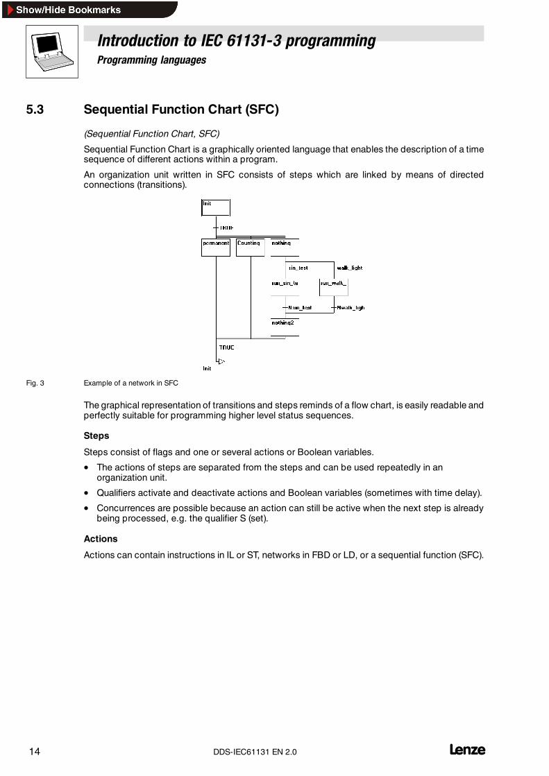
An organization unit written in SFC consists of steps which are linked by means of directedconnections (transitions).
Fig. 3 Example of a network in SFC
The graphical representation of transitions and steps reminds of a flow chart, is easily readable andperfectly suitable for programming higher level status sequences.
Steps
Steps consist of flags and one or several actions or Boolean variables.
• The actions of steps are separated from the steps and can be used repeatedly in anorganization unit.
• Qualifiers activate and deactivate actions and Boolean variables (sometimes with time delay).
• Concurrences are possible because an action can still be active when the next step is alreadybeing processed, e.g. the qualifier S (set).
Actions
Actions can contain instructions in IL or ST, networks in FBD or LD, or a sequential function (SFC).
Introduction to IEC 61131-3 programmingProgramming languages
15l DDS-IEC61131 EN 2.0
Transitions
Transitions are between steps. A step that follows a transition is activated if the transition conditionis TRUE.
The following transition conditions are possible:
• Boolean variable
• Boolean address
• Boolean constant (TRUE)
• A sequence of instructions with a Boolean result in ST syntax ((i<=100) AND b)
• A sequence of instructions programmed in any language
Alternative branches
In SFC, two or more branches can be defined as alternative branches.
• Every alternative branch must start and end with a transition.
• Alternative branches can contain parallel branches and other alternative branches.
• An alternative branch starts with a horizontal line (alternative start) and ends with a horizontalline (alternative end) or a jump.
• If the step before the alternative start line is active, the first transition of every alternativebranch is evaluated from left to right. The first transition from the left that meets the transitioncondition TRUE is opened and all following steps are activated.
Parallel branches
In SFC, two or more branches can be defined as parallel branches.
• Every parallel branch must start and end with a step.
• Parallel branches can contain alternative branches or other parallel branches.
• A parallel branch starts with a double line (parallel start) and ends with a double line (parallelend) or a jump.
• If the step before the parallel start line is active and the transition condition after this step isTRUE, then the first steps of all parallel branches are activated. These branches areprocessed in parallel.
• The steps after the parallel end line are activated if all steps before are active and thetransition condition of this step is TRUE.
Jumps
A jump is a connection with the step whose name is indicated under the jump symbol.
Jumps are necessary because it is not allowed to create upwards or crossing connections.
Introduction to IEC 61131-3 programmingProgramming languages
16 lDDS-IEC61131 EN 2.0
5.4 Function Block Diagram (FBD)
(Function Block Diagram, FBD)
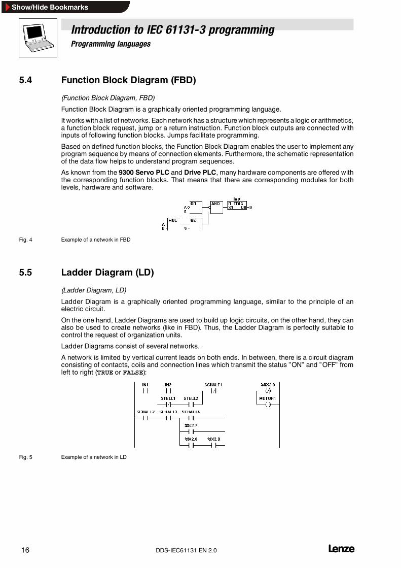
Function Block Diagram is a graphically oriented programming language.
It works with a list of networks. Each network has a structure which represents a logic or arithmetics,a function block request, jump or a return instruction. Function block outputs are connected withinputs of following function blocks. Jumps facilitate programming.
Based on defined function blocks, the Function Block Diagram enables the user to implement anyprogram sequence by means of connection elements. Furthermore, the schematic representationof the data flow helps to understand program sequences.
As known from the 9300 Servo PLC and Drive PLC, many hardware components are offered withthe corresponding function blocks. That means that there are corresponding modules for bothlevels, hardware and software.
Fig. 4 Example of a network in FBD
5.5 Ladder Diagram (LD)
(Ladder Diagram, LD)
Ladder Diagram is a graphically oriented programming language, similar to the principle of anelectric circuit.
On the one hand, Ladder Diagrams are used to build up logic circuits, on the other hand, they canalso be used to create networks (like in FBD). Thus, the Ladder Diagram is perfectly suitable tocontrol the request of organization units.
Ladder Diagrams consist of several networks.
A network is limited by vertical current leads on both ends. In between, there is a circuit diagramconsisting of contacts, coils and connection lines which transmit the status ”ON” and ”OFF” fromleft to right (TRUE or FALSE):
Fig. 5 Example of a network in LD
Introduction to IEC 61131-3 programmingProgramming languages
17l DDS-IEC61131 EN 2.0
Contacts
If a Boolean variable of a contact has the value TRUE, the status ”ON” is transmitted via theconnection line from left to right. Otherwise, the right connection is set to ”OFF” .
• Contacts can be switched in parallel. For this, one of the parallel branches must transmit thevalue ”ON” .
• Contacts can also be switched in series. For this, all contacts must transmit the status ”ON” .
• Contacts can also be negated (indicated by a slash in the contact symbol). The contacttransmits the input status if its status is ”OFF” (FALSE) ist.
Coils
In LD, an unlimited number of coils is available on the right side of a network (indicated by brackets).
• A coil transmits the connection value from left to right and copies the value to thecorresponding Boolean variable.
• The start line can be set to ”ON” or ”OFF” (depending on the Boolean values TRUE or FALSE).
• Coils can only be connected in parallel.
• Coils can also be negated (indicated by a slash in the contact symbol). They then copy thenegated value to the corresponding Boolean variable.
Set/reset coils
Coils can also be defined as set or reset coils.
A set coil (indicated by the letter ”S” in the coil symbol)can have the status ”ON” , but cannot be resetto ”OFF” .
• If the Boolean variable of the set coil has been set to TRUE, it cannot be reset to FALSE.
A reset coil (indicated by an ”R” in the coil symbol) can have the status ”OFF” , but cannot be resetto ”ON” .
• If the Boolean variable of the reset coil has been set to FALSE, it cannot be reset to TRUE.
Function blocks in LD
In addition to contacts and coils, it is also possible to enter function blocks and programs in LD.
Function blocks and programs must have an input and output with Boolean values in the network.They can be used at the same locations as the contacts, i.e. on the left side of the LD network.

Introduction to IEC 61131-3 programmingAppendix
18 LDDS-IEC61131 EN 2.0
6 Appendix
6.1 IEC keywords
Keywords are unique character combinations used as individual syntax elements.
• Keywords must not be used as identifiers.
• Keywords under the Drive PLC Developer Studio also include the names of Lenze functionblocks, that always start with ”L_” ( L_ABS , L_ADD , ...).
Keywords reserved for IEC 61131-3 programming languages:
ABS ACOS ACTION ADD AND ANDNANY ANY_BIT ANY_DATE ANY_INT ANY_NUM ANY_REALARRAY ASIN AT ATAN
BOOL BY BYTE
CAL CALC CALCN CASE CD CDTCLK CONCAT CONFIGURATION CONSTANT COS CTDCTU CTUD CU CV
DATE DATE_AND_TIME DELETE DINT DIV DODS DT DWORD
ELSE ESIF END_ACTION END_CASE END_CONFIGURATION END_FOREND_FUNCTION END_FUNCTION_BLOCK END_IF END_PROGRAM END_REPEATEND_RESOURCE END_STEP END_STRUCT END_TRANSITION END_TYPE END_VAREND_WHILE EN ENO EQ ET EXITEXP EXPT
FALSE F_EDGE F_TRIG FIND FOR FROMFUNCTION FUNCTION_BLOCK
GE GT
IF IN INITIAL_STEP INSERT INT INTERVAL
JMP JMPC JMPCN
L LD LDN LE LEFT LENLIMIT LINT LN LOG LREAL LTLWORD
MAX MID MIN MOD MOVE MULMUX
N NE NEG NOT
OF ON OR ORN
P PRIORITY PROGRAM PT PV
Introduction to IEC 61131-3 programmingAppendix
19L DDS-IEC61131 EN 2.0
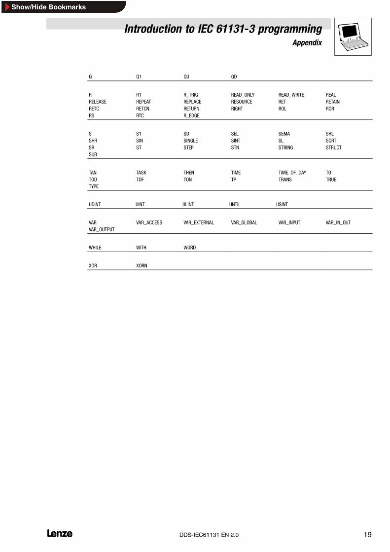
Q Q1 QU QD
R R1 R_TRIG READ_ONLY READ_WRITE REALRELEASE REPEAT REPLACE RESOURCE RET RETAINRETC RETCN RETURN RIGHT ROL RORRS RTC R_EDGE
S S1 SD SEL SEMA SHLSHR SIN SINGLE SINT SL SQRTSR ST STEP STN STRING STRUCTSUB
TAN TASK THEN TIME TIME_OF_DAY TOTOD TOF TON TP TRANS TRUETYPE
UDINT UINT ULINT UNTIL USINT
VAR VAR_ACCESS VAR_EXTERNAL VAR_GLOBAL VAR_INPUT VAR_IN_OUTVAR_OUTPUT
WHILE WITH WORD
XOR XORN
Introduction to IEC 61131-3 programmingAppendix
20 LDDS-IEC61131 EN 2.0
6.2 Conventions for Lenze variable identifiers
This chapter describes the conventions used for the variable identifiers of Lenze system blocks,function blocks and functions. The conventions ensure uniform and universal labelling and makereading the PLC program easier.
Tip!The conventions used by Lenze are based on the ”Hungarian Notation” . This ensures that the mostsignificant characteristics of a variable (e.g. the data type) can be instantly recognized from itsidentifier.
An identifier consists of
• a system block designation (only for identifiers of system block variables)
• a variable type entry (optional)
• a data type entry
• an identifier (the ”proper” name of the variable)
• a signal type entry (optional)
6.2.1 System block designation
(only for identifiers of system block variables)
The inputs/outputs of a system block are directly accessed via the corresponding I/O variables.
To indicate to which system block the I/O variables are assigned, the name of the correspondingsystem block followed by an underscore is written before the identifier.
Examples of system block designations:
AIN_
CAN1_
DIGIN_
Introduction to IEC 61131-3 programmingAppendix
21L DDS-IEC61131 EN 2.0
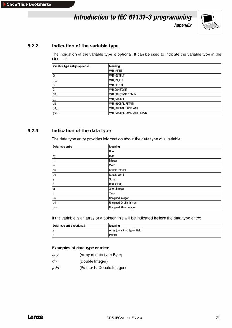
6.2.2 Indication of the variable type
The indication of the variable type is optional. It can be used to indicate the variable type in theidentifier:
Variable type entry (optional) Meaning
I_ VAR_INPUT
Q_ VAR_OUTPUT
IQ_ VAR_IN_OUT
R_ VAR RETAIN
C_ VAR CONSTANT
CR_ VAR CONSTANT RETAIN
g_ VAR_GLOBAL
gR_ VAR_GLOBAL RETAIN
gC_ VAR_GLOBAL CONSTANT
gCR_ VAR_GLOBAL CONSTANT RETAIN
6.2.3 Indication of the data type
The data type entry provides information about the data type of a variable:
Data type entry Meaning
b Bool
by Byte
n Integer
w Word
dn Double Integer
dw Double Word
s String
f Real (Float)
sn Short Integer
t Time
un Unsigned Integer
udn Unsigned Double Integer
usn Unsigned Short Integer
If the variable is an array or a pointer, this will be indicated before the data type entry:
Data type entry (optional) Meaning
a Array (combined type), field
p Pointer
Examples of data type entries:
aby (Array of data type Byte)
dn (Double Integer)
pdn (Pointer to Double Integer)
Introduction to IEC 61131-3 programmingAppendix
22 LDDS-IEC61131 EN 2.0
6.2.4 Identifier
The identifier is the proper name of a variable and should indicate the application or function of thevariable.
• Identifiers always start with a capital letter.
• If an identifier is assembled from several ”words” , then each ”word” must start with a capitalletter.
• All other letters are written in lower case.
Examples of identifiers:
JogValue
NumberOfValues
CurrentSelectedJogValue
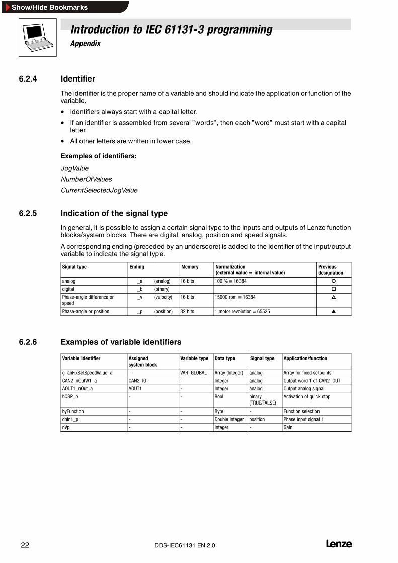
6.2.5 Indication of the signal type
In general, it is possible to assign a certain signal type to the inputs and outputs of Lenze functionblocks/system blocks. There are digital, analog, position and speed signals.
A corresponding ending (preceded by an underscore) is added to the identifier of the input/outputvariable to indicate the signal type.
Signal type Ending Memory Normalization(external value ≡≡≡≡ internal value)
Previousdesignation
analog _a (analog) 16 bits 100 % ≡ 16384 �
digital _b (binary) �
Phase-angle difference orspeed
_v (velocity) 16 bits 15000 rpm ≡ 16384 �
Phase-angle or position _p (position) 32 bits 1 motor revolution ≡ 65535 �
6.2.6 Examples of variable identifiers
Variable identifier Assignedsystem block
Variable type Data type Signal type Application/function
g_anFixSetSpeedValue_a - VAR_GLOBAL Array (Integer) analog Array for fixed setpoints
CAN2_nOutW1_a CAN2_IO - Integer analog Output word 1 of CAN2_OUT
AOUT1_nOut_a AOUT1 - Integer analog Output analog signal
bQSP_b - - Bool binary(TRUE/FALSE)
Activation of quick stop
byFunction - - Byte - Function selection
dnIn1_p - - Double Integer position Phase input signal 1
nVp - - Integer - Gain
Introduction to IEC 61131-3 programmingAppendix
23L DDS-IEC61131 EN 2.0
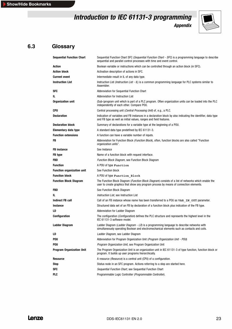
6.3 Glossary
Sequential Function Chart Sequential Function Chart SFC (Sequential Function Chart - SFC) is a programming language to describesequential and parallel control processes with time and event control.
Action Boolean variable or instructions which can be controlled through an action block (in SFC).
Action block Activation description of actions in SFC.
Current event Intermediate result in IL of any data type.
Instruction List Instruction List (Instruction List - IL) is a common programming language for PLC systems similar toAssembler.
SFC Abbreviation for Sequential Function Chart
IL Abbreviation for Instruction List
Organization unit (Sub-)program unit which is part of a PLC program. Often organization units can be loaded into the PLCindependently of each other. Compare POU.
CPU Central processing unit (Central Processing Unit) of, e.g., a PLC.
Declaration Indication of variables and FB instances in a declaration block by also indicating the identifier, data typeand FB type as well as initial values, ranges and field features.
Declaration block Summary of declarations for a variable type at the beginning of a POU.
Elementary data type A standard data type predefined by IEC 61131-3.
Function extensions A function can have a variable number of inputs.
FB Abbreviation for Function Block (Function Block), often, function blocks are also called ”Functionorganization units”.
FB instance See Instance
FB type Name of a function block with request interface.
FBD Function Block Diagram, see Function Block Diagram
Function A POU of type Function
Function organization unit See Function block
Function block A POU of type Function_Block
Function Block Diagram The Function Block Diagram (Function Block Diagram) consists of a list of networks which enable theuser to create graphics that show any program process by means of connection elements.
FBD See Function Block Diagram
IL Instruction List, see Instruction List
Indirect FB call Call of an FB instance whose name has been transferred to a POU as VAR_IN_OUT parameter.
Instance Structured data set of an FB by declaration of a function block plus indication of the FB type.
LD Abbreviation for Ladder Diagram
Configuration The configuration (Configuration) defines the PLC structure and represents the highest level in theIEC 61131-3 software model.
Ladder Diagram Ladder Diagram (Ladder Diagram - LD) is a programming language to describe networks withsimultaneously operating Boolean and electromechanical elements such as contacts and coils.
LD Ladder Diagram, see Ladder Diagram
POU Abbreviation for Program Organization Unit (Program Organization Unit - POU)
POU Program Organization Unit, see Program Organization Unit
Program Organization Unit The Program Organization Unit is an organization unit in IEC 61131-3 of type function, function block orprogram. It builds up user programs hierarchically.
Resource A resource (Resource) is a central unit (CPU) of a configuration.
Step Status node in an SFC program. Actions referring to a step are started here.
SFC Sequential Function Chart, see Sequential Function Chart
PLC Programmable Logic Controller (Programmable Controller).
Introduction to IEC 61131-3 programmingAppendix
24 LDDS-IEC61131 EN 2.0
ST Abbreviation for Structured Text.
Standard functions All functions predefined by IEC 61131-3 to implement PLC typical functionality.
Standard organization units See Standard function blocks
Standard function blocks All function blocks (Function Blocks) predefined by IEC 61131-3 to implement PLC typical functionality.
Structured Text Structured Text (Structured Text) is a programming language to describe algorithms and execution controlby means of the latest high languages.
Task Definition of run time features of a program.
Transition Transition from one SFC step to the next by evaluation of the transition condition.
Type definition Definition of a user-specific data type based on already existing data types.
Variable Name of a data memory which can contain values determined by the data type or variable declaration.
Cycle The cycle of a (periodically called) user program.
Cycle time The cycle time is the time needed by the user progam for a cycle.