Embed Size (px)
Citation preview

[Nerkar, 5(8): August 2018] ISSN 2348 – 8034 DOI- 10.5281/zenodo.1403100 Impact Factor- 5.070
(C)Global Journal Of Engineering Science And Researches
291
GLOBAL JOURNAL OF ENGINEERING SCIENCE AND RESEARCHES
DESIGN ASPECTS AND IMPLEMENTATION OF LINE FOLLOWER ROBOT Sachin S. Nerkar*
1& Shirish G. Adam
2
*1&2Assistant Professor, Instrumentation Department, Government College of Engineering, Jalgaon
ABSTRACT The Line follower robot is developed under e-yanta robotics laboratory. Firebird V will help to gain exposure to the
word of robotics and Embedded System. The aim of this robot is to follow the white line. Firebird V consists of
micro-controller ATMEGA-2560. The line follower is a self-operating robot that detects and follows a line that is
drawn on the floor. The path consists of a white line on a black surface. The control system used must sense a line
and maneuver the robot to stay on course, while constantly correcting the wrong moves using feedback mechanism,
thus forming a simple yet effective closed loop System. The robot is designed to follow very tight curves. It has
sensing element which sense environment around it so that it can move without any obstacle. The motor such as dc,
servo can be used as an actuator for our mechanical action. In this Paper, we have illustrated the process of design, implementation of line follower robot designed for the line follower robots competition.
Keywords: Firebird V, Embedded System, ATMEGA-2560
I. INTRODUCTION
The Fire Bird V robot is the fifth in the Fire Bird series of robots. First two versions of the robots designed for the
Embedded Real-Time Systems Lab, Department of Computer Science and Engineering, IIT Bombay. Theses
platforms were make commercially available from the version 3 onwards. All the Fire Bird V series robots share the
same main board and other accessories. Different family of microcontrollers can be add by simply changing top
microcontroller adapter board. Fire Bird V supports ATMEGA2560 (AVR), P89V51RD2 (8051) and LPC2148
(ARM7) microcontroller adapter boards. This modularity in changing the microcontroller adapter boards makes Fire
Bird V robots very versatile. You can also add your own custom designed microcontroller adapter board.
Fire Bird V ATMEGA2560 (AVR)
Figure1: Fire Bird V Robots

[Nerkar, 5(8): August 2018] ISSN 2348 – 8034 DOI- 10.5281/zenodo.1403100 Impact Factor- 5.070
(C)Global Journal Of Engineering Science And Researches
292
II. SPECIFICATIONS
Fire Bird V ATMEGA2560 technical specification:
Microcontroller:
Atmel ATMEGA2560 as Master microcontroller (AVR architecture based Microcontroller)
Atmel ATMEGA8 as Slave microcontroller (AVR architecture based Microcontroller)
Sensors:
Three white line sensors (extendable to 7)
Five Sharp GP2Y0A02YK IR range sensor (One in default configuration)
Eight analog IR proximity sensors
Two position encoders (extendable to four)
Battery voltage sensing
Current Sensing (Optional)
Five MaxBotix Ultrasonic Range Sensors (Optional)
Indicators:
2 x 16 Characters LCD
Buzzer and Indicator LEDs.
Controls:
Autonomous control
PC as Master and Robot as Slave in wired or wireless mode
Communiccation:
USB Communication Wired RS232 (serial) communication
Wireless ZigBee Communication (2.4GHZ) (if XBee wireless module is installed)
Wi-Fi communication (if Wi-Fi module is installed)
Bluetooth communication (if Bluetooth wireless module is installed)
Simplex infrared communication (From infrared remote to robot)
Dimensions:
Diameter: 16cm
Height: 8.5cm
Weight: 1100gms
Power:
9.6V Nickel Metal Hydride (NiMH) battery pack and external Auxiliary power from battery charger. On Board Battery monitoring and intelligent battery charger.
Battery Life:
2 Hours, while motors are operational at 75% of time.
Locomotion:
Two DC geared motors in differential drive configuration and caster wheel at front as support
Top Speed: 24 cm / second
Wheel Diameter: 51mm
Position encoder: 30 pulses per revolution
Position encoder resolution: 5.44 mm.
Fire Bird V robot has 6 important modules: a. Power Management
b. Sensing
c. Actuation (Locomotion)
d. Other Peripherals
e. Communication
f. Intelligence (Microcontroller)

[Nerkar, 5(8): August 2018] ISSN 2348 – 8034 DOI- 10.5281/zenodo.1403100 Impact Factor- 5.070
(C)Global Journal Of Engineering Science And Researches
293
III. BLOCK DIAGRAM
Figure 2: Architecture of Fire Bird V
IV. FIRE BIRD V ROBOT CONNECTIONS:
Figure 3: Fire Bird V ATMEGA2560 robot bottom view
Figure 4: ATMEGA2560 microcontroller adapter board

[Nerkar, 5(8): August 2018] ISSN 2348 – 8034 DOI- 10.5281/zenodo.1403100 Impact Factor- 5.070
(C)Global Journal Of Engineering Science And Researches
294
V. DESIGN REQUIREMENTS AND HARDWARE
Fire Bird V has on board rechargeable 9.6V, 2.1Ah Nickel
Metal Hydride battery which can power the robot for approximately 2 hours. Battery is fixed using Velcro strap so
that it can be replaced easily. In case the experiments are to be performed for an extended period, robot can also be
powered by external auxiliary power supply.
Figure 5: Power Switch
Power Management System on the Fire Bird V
Fire Bird V is powered by 9.6V rechargeable Nickel Metal Hydride battery pack. The battery voltage can vary between 12V (fully charged) to 8V (discharged). Battery pack should not be discharged below 8V (1V per cell) for
extended battery life. Fire Bird V robot has on-board intelligent NiMH battery charger which follows the correct
charging profile for the batteries. To avoid any accidental damage to the batteries, do not use external battery
charger.
Power sources and voltage regulation on the main board
Fire Bird V is primarily powered by NiMH battery. Auxiliary supply provides regulated 12V, 1Amp supply. When
robot is powered by battery, it can use maximum of 2Amp current while Auxiliary supply will provide only 1Amp
current.
Robot's power is divided in two separate power rails. “V Mot Supply” provides power to all the noisy devices on the
robot such as motors and other heavy loads. “V Batt Supply” powers most of the electronics on the robot. Most of the systems on the robot are powered by 3.3V and 5V via voltage regulators.
1. V Battery Supply
“V Battery Supply” stands for stabilized supply coming from the battery. This supply line is used to power almost
all the payload on the robot. When battery is almost discharged (about 30% power remaining) and onboard payload
draws current in excess of 2 amperes, then the battery voltage can fall below 6.3V momentary. Voltage regulators
will not be able to function properly below 6.3V and their output will fall below 5V. In this case the microcontroller
can reset. To extend the usable battery life and to reduce the probability of microcontroller getting reset when
battery is about to fully discharge, diodes D7 along with the capacitor C54 is used. When battery voltage suddenly
drops, diode D7 prevents the reverse flow of the current and capacitor C54 maintains voltage within safe limits for
about 100 milliseconds. For this duration capacitor C54 acts as small battery. Similar arrangement is done in the “V Mot Supply” using diodes D9 and capacitor C53. This scheme extends usable range of the fully charged battery.
2. V Mot Supply
“V Mot Supply” stands for motor supply. It is used to power DC motors and other heavy loads which have lots of
current fluctuations. It is the nosiest supply line on the robot. It should be used for heavy loads that require large
amount of current. This supply can be varied between 8V to 11.3V depending on the battery's charging state and
type of power source (battery / auxiliary power) used. This line can supply additional 500mA to the external load.

[Nerkar, 5(8): August 2018] ISSN 2348 – 8034 DOI- 10.5281/zenodo.1403100 Impact Factor- 5.070
(C)Global Journal Of Engineering Science And Researches
295
3. 5V System
“5V System” is used to power various modules of the robots which does not require high current and where voltage
stability is very important. It is used to power logic supply of the ICs, Sharp sensors, LCD etc. It is the most stable source of the supply on the main board. It can source 400mA current for the external load.
4. 3.3V Sensor
“3.3V Sensor” is used to power 8 IR proximity sensors, up to 7 white line sensors. In fully loaded Fire Bird V robot
this supply should not be used to power external load having current requirement more than 100mA.
5. 3.3V Wireless module
3.3V Wireless module supply is used to power XBee wireless module.Batt Mon Supply provides 3.3V to the Smart
battery monitoring and charger circuit.
VI. MOTION CONTROL
Fire Bird V robot has two 75 RPM DC geared motors in differential drive configuration along with the third caster
wheel for the support. Robot has top speed of about 24cm per second. Using this configuration, the robot can turn
with zero turning radius by rotating one wheel in clockwise direction and other in counter clockwise direction.
Position encoders are mounted on both the motor‟s axles to give a position feedback to the microcontroller.
Figure 6: DC geared motors and position encoders
Motion control involves velocity and direction control. Motors are controlled by L293D dual motor driver which can
provide up to 600mA of current to each motor. To change the direction of the motor, appropriate logic levels
(High/Low) are applied to L293D‟s direction control pins.Velocity control is done using Pulse Width Modulation
(PWM).
LEDs are connected at the input stage of the motor driver for quick interpretation of the motion commands. Pin
diagram of L293D IC is as shown in figure.

[Nerkar, 5(8): August 2018] ISSN 2348 – 8034 DOI- 10.5281/zenodo.1403100 Impact Factor- 5.070
(C)Global Journal Of Engineering Science And Researches
296
L293D is a dual H-bridge motor driver integrated circuit (IC). Motor drivers act as current amplifiers since they take
a low-current control signal and provide a higher-current signal. This higher current signal is used to drive the
motors.
L293D contains two inbuilt H-bridge driver circuits. In its common mode of operation, two DC motors can be driven simultaneously, both in forward and reverse direction. The motor operations of two motors can be controlled
by input logic at pins 2 & 7 and 10 & 15. Input logic 00 or 11 will stop the corresponding motor. Logic 01 and 10
will rotate it in clockwise and anticlockwise directions, respectively.
Enable pins 1 and 9 (corresponding to the two motors) must be high for motors to start operating. When an enable
input is high, the associated driver gets enabled. As a result, the outputs become active and work in phase with their
inputs. Similarly, when the enable input is low, that driver is disabled, and their outputs are off and in the high-
impedance state.
VII. SHARP IR RANGE SENSORS
For accurate distance measurement, robot uses Sharp IR range sensors. Robot can be fitted with five IR range
sensors as shown in figure 3.6.1. Sharp IR range sensors consists of IR LED and linear CCD array, both
encapsulated in the housing with precision lens assembly mounted in front of them. IR LED with the help of the
leans transmits a narrow IR beam. When light hits the obstacle and reflects back to the linear CCD array, depending
on the distance from the obstacle, angle of the reflected light varies. This angle is measured using the CCD array to
estimate distance from the obstacle. It gives same response to different colored objects as measured distance is
function of the angle of reflection and not on the reflected light intensity.
Figure 3.6.2.shows the internals of the sensor. Figure 3.6.3. explains how change in the distance from the obstacle
can be measured by measuring angle of reflection of the reflected light beam from the obstacle. Since sensor measurement is based on triangulation and not on intensity of the reflected light, it is immune to disturbance caused
by ambient light.
Sensor gives out analog voltage corresponding to angle of reflection. Relationship between the angle of reflection
and output voltage is not linear because of trigonometry involved. These sensors have blind spot in the range of
0mm to some specific distance depending on the type of the sensor. In the blind spot region sensor gives incorrect
readings. Table 3.6.1 gives information about sensing range and the blind spot distance for the particular sensor.

[Nerkar, 5(8): August 2018] ISSN 2348 – 8034 DOI- 10.5281/zenodo.1403100 Impact Factor- 5.070
(C)Global Journal Of Engineering Science And Researches
297
Figure 7: Sharp Sensors mounted on Fire Bird V
Figure 8 : Infrared Range finder sensor and its inside view
Figure 9: Sharp IR Range sensors for Fire Bird V
Table 3.6.1: Sharp IR Range sensors coverage
Sensor Range Blind Spot
GP2D120X 30cm to 20cm 4cm to 0cm
GP2Y0A02YK 80cm to 10cm 10cm to 0cm
GP2Y0A02 150cm to 20cm 20cm to 0cm

[Nerkar, 5(8): August 2018] ISSN 2348 – 8034 DOI- 10.5281/zenodo.1403100 Impact Factor- 5.070
(C)Global Journal Of Engineering Science And Researches
298
VIII. INFRARED PROXIMITY AND DIRECTIONAL LIGHT INTENSITY SENSORS
Infrared proximity sensors are used to detect proximity of any obstacles in the short range. IR proximity sensors
have about 10cm sensing range. These sensors sense the presence of the obstacles in the blind spot region of the
Sharp IR range sensors. Fire Bird V robot has 8 IR proximity sensors. Figure 3.7.1 shows the location of the 8 IR
proximity sensors. Sensors are numbered as 1 to 8 from left to right in clockwise direction.
In the absence of the obstacle there is no reflected light hence no leakage current will flow through the photo diode
and output voltage of the photo diode will be around 3.3V. As obstacle comes closer, more light gets reflected and
falls on the photo diode and leakage current flowing through the photo diode starts to increase which causes voltage
across the diode to fall.
Figure 10: Eight IR proximity sensors on Fire Bird V
IX. WHITE LINE SENSORS
White line sensors are used for detecting white line on the ground surface. White lines are used to give robot sense
of localization. White line sensor consists of a highly directional photo transistor for line sensing and bright red LED
for the illumination. Due to the directional nature of the photo diode it does not get affected with ambient light
unless it is very bright.
Figure 11: White line sensor

[Nerkar, 5(8): August 2018] ISSN 2348 – 8034 DOI- 10.5281/zenodo.1403100 Impact Factor- 5.070
(C)Global Journal Of Engineering Science And Researches
299
Figure 12: White Line sensor
When the robot is not on a white line, amount of light reflected is less, hence less leakage current flows through the
photo transistor. In this case, the line sensor gives an output in the range of 2V to 3.3V. When the sensor is on a
white line, more light gets reflected resulting in considerable increase in the leakage current which causes voltage
across the sensor to fall between 2 to 0.1V. Power to the red LEDs of white line sensor is controlled PG5 of
ATMEGA2560 microcontroller to extend robot‟s battery life. Switching action of the power control circuit is
exactly same as power switching circuit of IR proximity sensors as discussed in section 3.7. Line sensors can be
permanently turned on by inserting jumper in the Jumper J1-4. Schematic of the white line sensor module on the main board and location of potentiometers for the white line sensor calibration. Standard Fire Bird V robot has 3
channel white line sensor module. It can also be seamlessly upgraded to 7 channel white line sensor module using
the same connector. Main board has potentiometers for 7 inch white line sensors.
Figure 13: Potentiometers for white line sensor calibration
Figure 14: White line sensor pin connections (White line Sensor Board)
Figure 15: White line white line sensor connector pin configuration on main board

[Nerkar, 5(8): August 2018] ISSN 2348 – 8034 DOI- 10.5281/zenodo.1403100 Impact Factor- 5.070
(C)Global Journal Of Engineering Science And Researches
300
Table 1: White line sensor pin connections
Pin No. Function
1 White line sensor 1 (Left sensor) Data Out
2 White line sensor 1 LED via potentiometer
3 White line sensor 2 (Center Sensor) Data
Out
4 White line sensor 2 LED via potentiometer
5 White line sensor 3 (Right sensor) Data Out
6 White line sensor 3 LED via potentiometer
7 White line sensor 4 Data Out
8 White line sensor 4 LED via
potentiometer*
9 White line sensor 5 Data Out
10 White line sensor 5 LED via
potentiometer*
11 White line sensor 6 Data Out
12 White line sensor 6 LED via
potentiometer*
13 White line sensor 7 Data Out
14 White line sensor 7 LED via
potentiometer*
15 GND
16 GND
17 White Line switch(Jumper).
18 White Line switch(Jumper).
19 3V3 Sensor supply
20 3V3 Sensor supply
* Potentiometers for white line sensor no. 5 to 7 needs to be soldered and are not included in the package.
X. SOFTWARE DESCRIPTION
Working with AVR Studio
AVR studio is an Integrated Development Environment (IDE) by ATMEL for developing applications based on 8-
bit AVR microcontroller.
AVR microcontrollers find many applications as embedded systems; they are also used in the Arduino line of open
source board designs.
We have performed following task on the Fire Bird V.
Task-1: Introduction to Embedded C and ATMEL Studio 6.0
Experiment-1: Getting Familiar with ATMEL Studio and code debugging
The aim of this experiment is to get familiar with (Integrated Development Environment) IDE and debugging syntax
errors. We have used the ATMEL Studio IDE to open an existing project.
Experiment-2: Write your C-program
The motive of this experiment is to understand functions, variables and decision statements in C. You are expected
to write a function which returns „S‟, if both LSB and MSB of a number are set, returns „R‟, if both LSB and MSB
of number are not set, returns „L‟ if LSB is set but not the MSB and returns „M‟ if MSB is set but not the LSB.

[Nerkar, 5(8): August 2018] ISSN 2348 – 8034 DOI- 10.5281/zenodo.1403100 Impact Factor- 5.070
(C)Global Journal Of Engineering Science And Researches
301
Task-2: I/O interfacing on AVR based controllers
Experiment-1: Getting Familiar with I/O port operation – Blinking LEDs and interfacing buzzer. The aim of this experiment is to get you familiar with I/O Ports of Atmega 2560 micro controller, when used as
output ports. In this experiment, we have interfaced the output devices (bar graph LED and buzzer) with the micro
controller. Bar graph LED comprises of 10 LEDs included in a single module and 8 LEDs out of the 10 are
connected to Port J of Atmega 2560 micro controller and Buzzer is connected to pin 3 of Port C.
The task is to turn OFF each bar LED one by one with a delay of 1 second and then turn ON the buzzer for 1 second
when all the 8 LEDs have been turned OFF.
1. Initially all the LEDs remain ON
2. Turn OFF each bar graph LED one by one from the top with a delay of 1 second between them.
3. Turn ON the Buzzer for 1 second when all the 8 LEDs have been turned OFF
4. Turn OFF the Buzzer and turn ON all the LEDs 5. Repeat the steps from 1 to 4 again.
Experiment-2: Interface a switch to turn ON Bar graph LEDs (“Push to ON” indicator)
The aim of this experiment is to get you familiar with I/O Ports of Atmega 2560 micro controller, when used as
input ports. In this experiment, you will interface an input device (boot switch) with the micro controller. The boot
switch (Refer to Figure 1) is located right beside the reset switch on the Firebird V robot.
Figure 16: Boot switch on Firebird-V robot (marked in red rectangle)
Task is to implement a “Push to ON” indicator using a set of bar LEDs (part of the Bar graph LED) connected to
Port J and a boot switch connected to Port E pin number 7.
This experiment involves counting boot switch presses and indicating each press on the bar graph LEDs.
Your task is to program Firebird V to implement the following on detecting each boot switch press.
First boot switch Press: The 4 odd numbered LEDs (1, 3, 5 and 7) connected to Port J should be turned ON one by
one with a delay of 1 second between them and remain ON until third boot switch press. Here the LEDs are “1”
indexed. Only 8 out of the 10 bar LEDs can are connected to Port J.
Second boot switch Press: After second press of boot switch, 4 even numbered LEDs (2, 4, 6, 8) connected to Port J should be turned ON one by one with a delay of one second and remain ON until boot switch is pressed again.
Third boot switch Press: Third press of the boot switch will turn OFF all the 8 LEDs.
Task-3: Interfacing LCD
Experiment-1: Displaying mathematical multiplication table of any number (from 0 to 255) on the LCD.
The aim of this experiment is to get you familiar with LCD interfacing on the ATmega2560 based Firebird V robotic
kit. In this experiment, you will write program code to interface a 16x2 LCD with ATMEGA 2560 microcontroller.
The 16x2 LCD is connected to Port C of ATmega2560.
Refer to the LCD pin connection table below:
[Nerkar, 5(8): August 2018] ISSN 2348 – 8034 DOI- 10.5281/zenodo.1403100 Impact Factor- 5.070
(C)Global Journal Of Engineering Science And Researches
302
Table 2: LCD pin connection
LCD pins Microcontroller Port
C pins
Register Select (RS)
Pin no.1 (PC0)
Read/Write (R/W)
Pin no.2 (PC1)
Enable (EN)
Pin No.3(PC2)
Data bus (DB7)
Pin no.8 (PC7)
Data bus (DB6)
Pin no.7 (PC6)
Data bus (DB5)
Pin no.6 (PC5)
Data bus (DB4)
Pin no.5 (PC4)
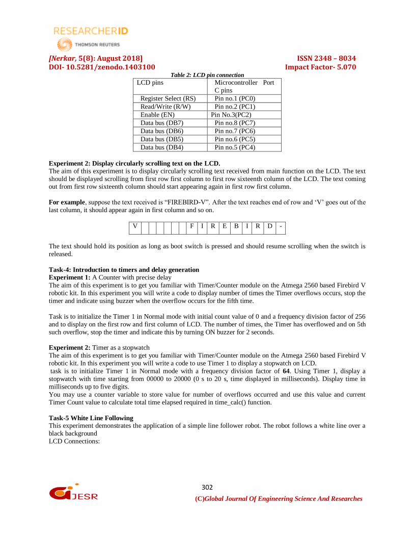
Experiment 2: Display circularly scrolling text on the LCD. The aim of this experiment is to display circularly scrolling text received from main function on the LCD. The text
should be displayed scrolling from first row first column to first row sixteenth column of the LCD. The text coming out from first row sixteenth column should start appearing again in first row first column.
For example, suppose the text received is “FIREBIRD-V”. After the text reaches end of row and „V‟ goes out of the
last column, it should appear again in first column and so on.
V F I R E B I R D -
The text should hold its position as long as boot switch is pressed and should resume scrolling when the switch is
released.
Task-4: Introduction to timers and delay generation Experiment 1: A Counter with precise delay
The aim of this experiment is to get you familiar with Timer/Counter module on the Atmega 2560 based Firebird V
robotic kit. In this experiment you will write a code to display number of times the Timer overflows occurs, stop the
timer and indicate using buzzer when the overflow occurs for the fifth time.
Task is to initialize the Timer 1 in Normal mode with initial count value of 0 and a frequency division factor of 256
and to display on the first row and first column of LCD. The number of times, the Timer has overflowed and on 5th
such overflow, stop the timer and indicate this by turning ON buzzer for 2 seconds.
Experiment 2: Timer as a stopwatch
The aim of this experiment is to get you familiar with Timer/Counter module on the Atmega 2560 based Firebird V
robotic kit. In this experiment you will write a code to use Timer 1 to display a stopwatch on LCD.
task is to initialize Timer 1 in Normal mode with a frequency division factor of 64. Using Timer 1, display a
stopwatch with time starting from 00000 to 20000 (0 s to 20 s, time displayed in milliseconds). Display time in
milliseconds up to five digits.
You may use a counter variable to store value for number of overflows occurred and use this value and current
Timer Count value to calculate total time elapsed required in time_calc() function.
Task-5 White Line Following This experiment demonstrates the application of a simple line follower robot. The robot follows a white line over a
black background
LCD Connections:

[Nerkar, 5(8): August 2018] ISSN 2348 – 8034 DOI- 10.5281/zenodo.1403100 Impact Factor- 5.070
(C)Global Journal Of Engineering Science And Researches
303
Microcontroller Pins:
RS -->PC0
RW -->PC1
EN -->PC2
DB7 -->PC7
DB6 -->PC6
DB5 -->PC5
DB4 -->PC4
ADC Connection: Table 3: ADC pin connection
ACD
CH.
PORT Sensor
0 PF0 Battery Voltage
1 PF1 White line sensor 3
2 PF2 White line sensor 2
3 PF3 White line sensor 1
4 PF4 IR Proximity analog sensor 1
5 PF5 IR Proximity analog sensor 2
6 PF6 IR Proximity analog sensor 3
7 PF7 IR Proximity analog sensor 4
8 PK0 IR Proximity analog sensor 5
9 PK1 Sharp IR range sensor 1
10 PK2 Sharp IR range sensor 2
11 PK3 Sharp IR range sensor 3
12 PK4 Sharp IR range sensor 4
13 PK5 Sharp IR range sensor 5
14 PK6 Servo Pod 1
15 PK7 Servo Pod 2
For using Analog IR proximity (1, 2, 3 and 4) sensors short the jumper J2. To use JTAG via expansion slot of the
microcontroller socket remove these jumpers.
Motion control Connection:
L-1---->PA0; L-2---->PA1; R-1---->PA2; R-2---->PA3;
PL3 (OC5A) ----> PWM left;
PL4 (OC5B) ----> PWM right;
XI. CONCLUSION
In this paper, a robot designed with an affordable and advanced technology. With the help of this setup, we are able
to follow white line with very tight curves. It has sensing element which sense environment around it so that it can
move without any obstacle. It can be easily applied and adapted to various applications like autonomous control vehicles. The robot is controlled by the microcontroller. It performs and changes the motor direction by giving
signal to driver IC according to reception of signals from sensors.

[Nerkar, 5(8): August 2018] ISSN 2348 – 8034 DOI- 10.5281/zenodo.1403100 Impact Factor- 5.070
(C)Global Journal Of Engineering Science And Researches
304
XII. ACKNOWLEDGMENT
Completion of any task would not be complete without expression of gratitude to all those who helped in doing this
task. We are extremely grateful to Instrumentation Engineering Department and the entire staff members from
Department and our friends for inspiring us towards ensuring and retaining the quality of work.
REFERENCES 1. Mehran Pakdaman, M. Mehdi Sanaatiyan, “Design and Implementation of Line Follower Robot”, Second
International Conference on Computer and Electrical Engineering 2009, pp. 585 - 590.
2. Kazi Mahmud Hasan ; Abdullah-Al-Nahid; Abdullah Al Mamun, “Implementation of autonomous line follower robot” 2012 International Conference on Informatics, Electronics & Vision (ICIEV) 2012, pp.
865 - 869
3. Priyank Patil, "AVR Line Following Robot," Department of Information Technology K. 1. Somaiya
College of Engineering Mumbai, India. Mar 5, 2010.
4. S. Krithivasan ; K. Lala ; K. Arya ; S. Shandilya ; S. Jain ; P. Manavar ; S. Patii , “e-Yantra lab setup
initiative: Sustainable knowledge creation and scalable infrastructure creation at engineering colleges” ,
2014 IEEE Frontiers in Education Conference (FIE) Proceedings,: 2014, pp: 1 – 8
5. Saraswathi Krithivasan ; Saurav Shandilya ; Sanam Shakya ; Kavi Arya ; Krishna Lala, “Building
Inclusiveness in a PBL Based Online Robotics Competition: Challenges and Outcomes”, 2016
International Conference on Learning and Teaching in Computing and Engineering (LaTICE), 2016 pp: 9
- 13