Embed Size (px)
Citation preview
Global View Station 1000GVS1000
en Installation Manual

Global View Station 1000 Table of Contents | en 3
Bosch Security Systems, Inc. Installation Manual F.01U.173.868 | 2.0 | 2010.11
Table of Contents
1 Safety 41.1 Important safety instructions 41.2 Important notices 61.3 Customer Support and Service 11
2 Product Description 12
3 Installation Preparation and Recommendations 133.1 Unpacking 133.2 Parts List 133.3 System Dimensions and Area Requirements 153.3.1 System Dimensions 153.3.2 Area Requirements 153.4 Motor Mount 153.5 Power Supply Mount Requirements 163.5.1 PSU Mount Setup 163.5.2 Installing the Wall Mount 17
4 System Block Diagram 18
5 Installation 195.1 System Assembly 195.2 Commissioning and Installation 225.2.1 Protocol Support 225.2.2 Site Requirements and Interfaces 235.2.3 Setting the System Address 245.2.4 Camera Configuration Default Setting 265.3 IR Alignment 285.3.1 ZX700 IR Alignment Procedure 285.3.2 SLED IR Alignment 29
6 Specifications 30
Index 29
4 en | Safety Global View Station 1000
F.01U.173.868 | 2.0 | 2010.11 Installation Manual Bosch Security Systems, Inc.
1 Safety
1.1 Important safety instructions
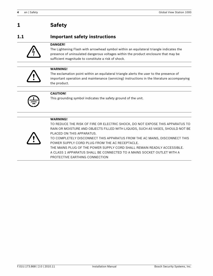
DANGER! The Lightening Flash with arrowhead symbol within an equilateral triangle indicates the presence of uninsulated dangerous voltages within the product enclosure that may be sufficient magnitude to constitute a risk of shock.
WARNING! The exclamation point within an equilateral triangle alerts the user to the presence of important operation and maintenance (servicing) instructions in the literature accompanying the product.
CAUTION! This grounding symbol indicates the safety ground of the unit.
WARNING! TO REDUCE THE RISK OF FIRE OR ELECTRIC SHOCK, DO NOT EXPOSE THIS APPARATUS TO RAIN OR MOISTURE AND OBJECTS FILLED WITH LIQUIDS, SUCH AS VASES, SHOULD NOT BE PLACED ON THIS APPARATUS.TO COMPLETELY DISCONNECT THIS APPARATUS FROM THE AC MAINS, DISCONNECT THIS POWER SUPPLY CORD PLUG FROM THE AC RECEPTACLE.THE MAINS PLUG OF THE POWER SUPPLY CORD SHALL REMAIN READILY ACCESSIBLE.A CLASS 1 APPARATUS SHALL BE CONNECTED TO A MAINS SOCKET OUTLET WITH A PROTECTIVE EARTHING CONNECTION
Global View Station 1000 Safety | en 5
Bosch Security Systems, Inc. Installation Manual F.01U.173.868 | 2.0 | 2010.11
1. Read these instructions. 2. Keep this instruction.3. Heed all warnings.4. Follow all instructions.5. Do not use this apparatus near water.6. Clean only with dry cloth.7. Do not block any ventilation openings. Install in accordance with manufacturer
instructions. 8. Do not install near any heat sources such as radiators, heat registers, stoves or other
apparatus (including amplifiers) that produce heat.9. Do not defeat the safety purpose of the polarized or grounding-type plug. A polarized
plug has two blades with one wider than the other. A grounding type plug has two blades and a third grounding prong. The wide blade or the third prong is provided for your safety. If the provided plug does not fit into your outlet, consult an electrician for replacement of the obsolete outlet.
10. Protect the power cord from being walked on or pinched particularly at plugs, convenience receptacles, and the power where they exit from the apparatus.
11. Only use attachments/accessories specified by the manufacturer.12. Use only with the cart, stand, tripod, bracket, or table specified by the manufacturer, or
sold with the apparatus. When a cart is used, use caution when moving the cart/apparatus combination to avoid injury from tip-over.
13. Unplug this apparatus during lightning storms or when unused for long periods of time. 14. Refer all servicing to qualified service personnel. Servicing is required when the
apparatus has been damaged in a way, such as power-supply cord or plug is damaged, liquid has been spilled or objects have fallen into the apparatus, the apparatus has been exposed to rain or moisture, does not operate normally, or has been dropped.
6 en | Safety Global View Station 1000
F.01U.173.868 | 2.0 | 2010.11 Installation Manual Bosch Security Systems, Inc.
1.2 Important notices
All-pole power switch - Incorporate an all-pole power switch, with a contact separation of at least 3 mm in each pole, into the electrical installation of the building. If it is needed to open the housing for servicing and/or other activities, use this all-pole switch as the main disconnect device for switching off the voltage to the unit.Camera grounding - For mounting the camera in potentially damp environments, ensure to ground the system using the ground connection of the power supply connector (see section: Connecting external power supply).Camera lens - An assembled camera lens in the outdoor housing must comply and be tested in accordance with UL/IEC60950. Any output or signal lines from the camera must be SELV or Limited Power Source. For safety reasons the environmental specification of the camera lens assembly must be within the environmental specification of -10 °C (14 °F) to 50 °C (122 °F).Camera signal - Protect the cable with a primary protector if the camera signal is beyond 140 feet, in accordance with NEC800 (CEC Section 60).Coax grounding:– Ground the cable system if connecting an outside cable system to the unit.– Connect outdoor equipment to the unit's inputs only after this unit has had its grounding
plug connected to a grounded outlet or its ground terminal is properly connected to a ground source.
– Disconnect the unit's input connectors from outdoor equipment before disconnecting the grounding plug or grounding terminal.
– Follow proper safety precautions such as grounding for any outdoor device connected to this unit.
U.S.A. models only - Section 810 of the National Electrical Code, ANSI/NFPA No.70, provides information regarding proper grounding of the mount and supporting structure, grounding of the coax to a discharge unit, size of grounding conductors, location of discharge unit, connection to grounding electrodes, and requirements for the grounding electrode.
Electronic Surveillance - This device is intended for use in public areas only. U.S. federal law strictly prohibits surreptitious recording of oral communications.Environmental statement - Bosch has a strong commitment towards the environment. This unit has been designed to respect the environment as much as possible.Electrostatic-sensitive device - Use proper CMOS/MOS-FET handling precautions to avoid electrostatic discharge.NOTE: Wear required grounded wrist straps and observe proper ESD safety precautions when handling the electrostatic-sensitive printed circuit boards.
Accessories - Do not place this unit on an unstable stand, tripod, bracket, or mount. The unit may fall, causing serious injury and/or serious damage to the unit. Use only with the cart, stand, tripod, bracket, or table specified by the manufacturer. When a cart is used, use caution and care when moving the cart/apparatus combination to avoid injury from tip-over. Quick stops, excessive force, or uneven surfaces may cause the cart/unit combination to overturn. Mount the unit per the manufacturer's instructions.
Disposal - Your Bosch product was developed and manufactured with high-quality material and components that can be recycled and reused. This symbol means that electronic and electrical appliances, which have reached the end of their working life, must be collected and disposed of separately from household waste material. Separate collecting systems are usually in place for disused electronic and electrical products. Please dispose of these units at an environmentally compatible recycling facility, per European Directive 2002/96/EC.
Global View Station 1000 Safety | en 7
Bosch Security Systems, Inc. Installation Manual F.01U.173.868 | 2.0 | 2010.11
Fuse rating - For security protection of the device, the branch circuit protection must be secured with a maximum fuse rating of 16A. This must be in accordance with NEC800 (CEC Section 60).Grounding and polarization - This unit may be equipped with a polarized alternating current line plug (a plug with one blade wider than the other blade). This safety feature allows the plug to fit into the power outlet in only one way. If unable to insert the plug fully into the outlet, contact a locally certified electrician to replace the obsolete outlet. Do not defeat the safety purpose of the polarized plug.Alternately, this unit may be equipped with a 3-pole grounding plug (a plug with a third pin for earth grounding). This safety feature allows the plug to fit into a grounded power outlet only. If unable to insert the plug into the outlet, contact a locally certified electrician to replace the obsolete outlet. Do not defeat the safety purpose of the grounding plug.Moving - Disconnect the power before moving the unit. Move the unit with care. Excessive force or shock may damage the unit and the hard disk drives.Outdoor signals - The installation for outdoor signals, especially regarding clearance from power and lightning conductors and transient protection, must be in accordance with NEC725 and NEC800 (CEC Rule 16-224 and CEC Section 60).Permanently connected equipment - Incorporate a readily accessible disconnect device in the building installation wiring.Pluggable equipment - Install the socket outlet near the equipment so it is easily accessible.Power resupply - If the unit is forced to power down due to exceeding the specified operating temperatures, disconnect the power cord, wait for at least 30 seconds, and then reconnect the power cord.Power lines - Do not locate the camera near overhead power lines, power circuits, or electrical lights, nor where it may contact such power lines, circuits, or lights.Rack-mount– Ventilation - Do not place this unit in a built-in installation or rack without proper
ventilation or adhering to the manufacturer's instructions. The equipment must not exceed its maximum operating temperature requirements.
– Mechanical loading - Properly mount the equipment in a rack to prevent a hazardous condition due to uneven mechanical loading.
SELVAll the input/output ports are Safety Extra Low Voltage (SELV) circuits. SELV circuits should only be connected to other SELV circuits.Because the ISDN circuits are treated like telephone-network voltage, avoid connecting the SELV circuit to the Telephone Network Voltage (TNV) circuits.The system ground is only used to comply with safety standards or installation practices in certain countries. Bosch does not recommend connecting system ground to safety ground unless it is explicitly required. However, if the system ground and safety ground are connected and grounding loops are causing interference in the video signal, use an isolation transformer (available separately from Bosch).
CAUTION! Connecting System ground to Safety ground may result in ground loops that can disrupt the CCTV system.
8 en | Safety Global View Station 1000
F.01U.173.868 | 2.0 | 2010.11 Installation Manual Bosch Security Systems, Inc.
Video loss - Video loss is inherent to digital video recording; therefore, Bosch Security Systems cannot be held liable for any damage that results from missing video information. To minimize the risk of lost digital information, Bosch Security Systems recommends multiple, redundant recording systems, and a procedure to back up all analog and digital information.
FCC & ICES Information(U.S.A. and Canadian Models Only)This equipment has been tested and found to comply with the limits for a Class B digital device, pursuant to part 15 of the FCC Rules. These limits are designed to provide reasonable protection against harmful interference in a residential installation. This equipment generates, uses, and can radiate radio frequency energy and, if not installed and used in accordance with the instructions, may cause harmful interference to radio communications. However, there is no guarantee that interference will not occur in a particular installation. If this equipment does cause harmful interference to radio or television reception, which can be determined by turning the equipment off and on, the user is encouraged to try to correct the interference by one or more of the following measures:– reorient or relocate the receiving antenna;– increase the separation between the equipment and receiver;– connect the equipment into an outlet on a circuit different from that to which the
receiver is connected;– consult the dealer or an experienced radio/TV technician for help.Intentional or unintentional modifications, not expressly approved by the party responsible for compliance, shall not be made. Any such modifications could void the user's authority to operate the equipment. If necessary, the user should consult the dealer or an experienced radio/television technician for corrective action.The user may find the following booklet, prepared by the Federal Communications Commission, helpful: How to Identify and Resolve Radio-TV Interference Problems. This booklet is available from the U.S. Government Printing Office, Washington, DC 20402, Stock No. 004-000-00345-4.
Global View Station 1000 Safety | en 9
Bosch Security Systems, Inc. Installation Manual F.01U.173.868 | 2.0 | 2010.11
INFORMATIONS FCC ET ICES(modèles utilisés aux États-Unis et au Canada uniquement)Suite à différents tests, cet appareil s'est révélé conforme aux exigences imposées aux appareils numériques de classe B, en vertu de la section 15 du règlement de la Commission fédérale des communications des États-Unis (FCC), et en vertu de la norme ICES-003 d'Industrie Canada. Ces exigences visent à fournir une protection raisonnable contre les interférences nuisibles lorsque l'appareil est utilisé dans le cadre d'une installation résidentielle. Cet appareil génère, utilise et émet de l'énergie de radiofréquences et peut, en cas d'installation ou d'utilisation non conforme aux instructions, engendrer des interférences nuisibles au niveau des radiocommunications. Toutefois, rien ne garantit l'absence d'interférences dans une installation particulière. Il est possible de déterminer la production d'interférences en mettant l'appareil successivement hors et sous tension, tout en contrôlant la réception radio ou télévision. L'utilisateur peut parvenir à éliminer les interférences éventuelles en prenant une ou plusieurs des mesures suivantes:– Modifier l'orientation ou l'emplacement de l'antenne réceptrice;– Éloigner l'appareil du récepteur;– Brancher l'appareil sur une prise située sur un circuit différent de celui du récepteur;– Consulter le revendeur ou un technicien qualifié en radio/télévision pour obtenir de
l'aide.Toute modification apportée au produit, non expressément approuvée par la partie responsable de l'appareil, est strictement interdite. Une telle modification est susceptible d'entraîner la révocation du droit d'utilisation de l'appareil.La brochure suivante, publiée par la Commission fédérale des communications (FCC), peut s'avérer utile : How to Identify and Resolve Radio-TV Interference Problems (Comment identifier et résoudre les problèmes d’interférences de radio et de télévision). Cette brochure est disponible auprès du U.S. Government Printing Office, Washington, DC 20402, États-Unis, sous la référence n° 004-000-00345-4.
DisclaimerUnderwriter Laboratories Inc. (“UL”) has not tested the performance or reliability of the security or signaling aspects of this product. UL has only tested fire, shock and/or casualty hazards as outlined in UP's Standard(s) for Safety for Closed Circuit Television Equipment, UL 2044. UL Certification does not cover the performance or reliability of the security or signaling aspects of this product.UL MAKES NO REPRESENTATIONS, WARRANTIES, OR CERTIFICATIONS WHATSOEVER REGARDING THE PERFORMANCE OR RELIABILITY OF ANY SECURITY OR SIGNALING RELATED FUNCTIONS OF THIS PRODUCT.
DisclaimerUnderwriter Laboratories Inc. (“UL”) has not tested the performance or reliability of the security or signaling aspects of this product. UL has only tested fire, shock and/or casualty hazards as outlined in UP's Standard(s) for Safety for Information Technology Equipment, UL 60950-1. UL Certification does not cover the performance or reliability of the security or signaling aspects of this product.UL MAKES NO REPRESENTATIONS, WARRANTIES, OR CERTIFICATIONS WHATSOEVER REGARDING THE PERFORMANCE OR RELIABILITY OF ANY SECURITY OR SIGNALING-RELATED FUNCTIONS OF THIS PRODUCT.
CopyrightThis manual is the intellectual property of Bosch Security Systems and is protected by copyright.
10 en | Safety Global View Station 1000
F.01U.173.868 | 2.0 | 2010.11 Installation Manual Bosch Security Systems, Inc.
All rights reserved.
TrademarksAll hardware and software product names used in this document are likely to be registered trademarks and must be treated accordingly.
NOTE!This manual has been compiled with great care and the information it contains has been thoroughly verified. The text was complete and correct at the time of printing. The ongoing development of the products may mean that the content of the user guide can change without notice. Bosch Security Systems accepts no liability for damage resulting directly or indirectly from faults, incompleteness or discrepancies between the user guide and the product described.
More informationFor additional information, please contact the Bosch Security Systems location nearest you or visit our web site at www.boschsecurity.com
Global View Station 1000 Safety | en 11
Bosch Security Systems, Inc. Installation Manual F.01U.173.868 | 2.0 | 2010.11
1.3 Customer Support and ServiceIf this unit needs service, contact the nearest Bosch Security Systems Service Center for authorization to return and shipping instructions.Service CentersUSARepair Center-Telephone: 800-566-2283Fax: 800-366-1329E-mail: [email protected] ServiceTelephone: 888-289-0096Fax: 585-223-9180E-mail: [email protected] SupportTelephone: 800-326-1450Fax: 585-223-3508 or 717-735-6560 E-mail: [email protected]: 514-738-2434 Fax: 514-738-8480 Europe, Middle East, Africa RegionRepair CenterTelephone: 31 (0) 76-5721500Fax: 31 (0) 76-5721413E-mail: [email protected] RegionRepair CenterTelephone: 65 63522776Fax: 65 63521776E-mail: [email protected] ServiceTelephone: 86 (0) 756 7633117 or 86 (0) 756 7633121Fax: 86 (0) 756 7631710E-mail: [email protected] and more informationFor additional information and warranty queries, please contact your Bosch Security Systems representative or visit our website at www.boschsecurity.com.
12 en | Product Description Global View Station 1000
F.01U.173.868 | 2.0 | 2010.11 Installation Manual Bosch Security Systems, Inc.
2 Product DescriptionThe GVS1000 is a system designed to deliver long range day/night pan-tilt-zoom surveillance. Delivering 1 km of Recognition-level performance and 1200 m of Classification-level performance in total darkness, the GVS1000 provides long range 24/7 imaging for critical applications such as port and maritime monitoring, transportation and airport surveillance, and border and extended perimeter security. To effectively perform to such capabilities, the GVS1000 is equipped with an IR-corrected, long range lens capable of 60x optical zoom. Providing a focal length of 12.5-750 mm or 25-1500 mm (with doubler function engaged), the lens works in tandem with the high performance Dinion XF sensor to produce ultra-high quality images at far distances in day and night conditions. The system capability is then greatly enhanced using active IR illumination. Two sets of illuminators are provided; one for long range, and one for medium to short range night imaging with no safety concerns, as is the case with laser based units. IR illumination can be controlled manually or put into automatic mode for auto on/off function via photocell. For control, the GVS1000 is compatible with Pelco P or Pelco D protocol input via RS422/485 or the Biphase protocol.
Global View Station 1000 Installation Preparation and Recommendations | en 13
Bosch Security Systems, Inc. Installation Manual F.01U.173.868 | 2.0 | 2010.11
3 Installation Preparation and RecommendationsFor safety, two people are recommended to assemble the system.
3.1 UnpackingCare should be taken when unpacking the shipped unit. Check the parts list and confirm all items have been located. Inspect the equipment thoroughly to ensure nothing was damaged in transit. Contact the Bosch Service Center if a problem is noted.
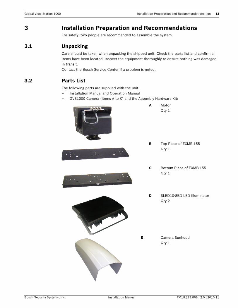
3.2 Parts ListThe following parts are supplied with the unit:– Installation Manual and Operation Manual– GVS1000 Camera (items A to K) and the Assembly Hardware Kit:
A MotorQty 1
B Top Piece of EXMB.155Qty 1
C Bottom Piece of EXMB.155Qty 1
D SLED10-8BD LED IlluminatorQty 2
E Camera SunhoodQty 1
14 en | Installation Preparation and Recommendations Global View Station 1000
F.01U.173.868 | 2.0 | 2010.11 Installation Manual Bosch Security Systems, Inc.
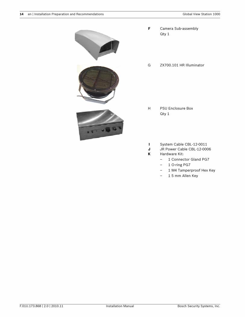
F Camera Sub-assemblyQty 1
G ZX700.101 HR Illuminator
H PSU Enclosure BoxQty 1
I System Cable CBL-12-0011J JR Power Cable CBL-12-0006K Hardware Kit:
– 1 Connector Gland PG7– 1 O-ring PG7– 1 M4 Tamperproof Hex Key– 1 5 mm Allen Key
Global View Station 1000 Installation Preparation and Recommendations | en 15
Bosch Security Systems, Inc. Installation Manual F.01U.173.868 | 2.0 | 2010.11
3.3 System Dimensions and Area Requirements
3.3.1 System Dimensions
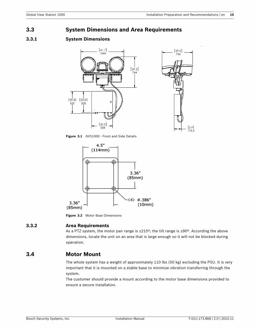
Figure 3.1 GVS1000 - Front and Side Details
Figure 3.2 Motor Base Dimensions
3.3.2 Area RequirementsAs a PTZ system, the motor pan range is ±215º; the tilt range is ±90º. According the above dimensions, locate the unit on an area that is large enough so it will not be blocked during operation.
3.4 Motor MountThe whole system has a weight of approximately 110 lbs (50 kg) excluding the PSU. It is very important that it is mounted on a stable base to minimize vibration transferring through the system.The customer should provide a mount according to the motor base dimensions provided to ensure a secure installation.
16 en | Installation Preparation and Recommendations Global View Station 1000
F.01U.173.868 | 2.0 | 2010.11 Installation Manual Bosch Security Systems, Inc.
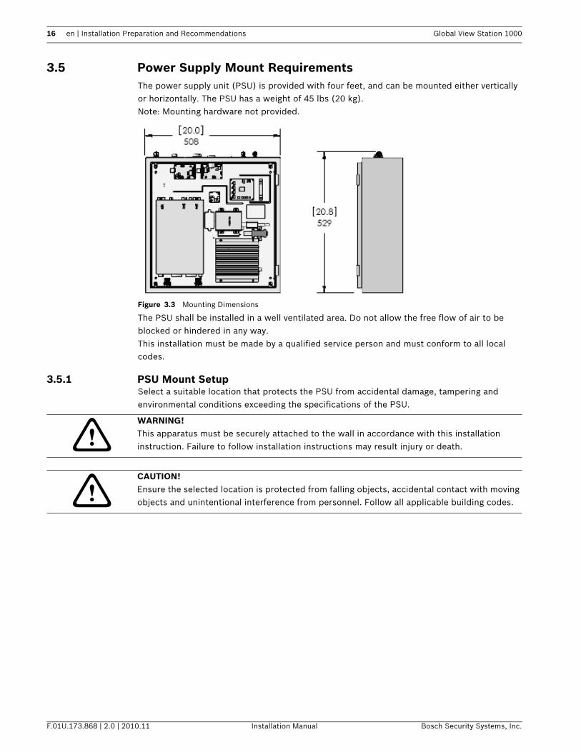
3.5 Power Supply Mount RequirementsThe power supply unit (PSU) is provided with four feet, and can be mounted either verticallyor horizontally. The PSU has a weight of 45 lbs (20 kg).Note: Mounting hardware not provided.
Figure 3.3 Mounting Dimensions
The PSU shall be installed in a well ventilated area. Do not allow the free flow of air to be blocked or hindered in any way.This installation must be made by a qualified service person and must conform to all local codes.
3.5.1 PSU Mount SetupSelect a suitable location that protects the PSU from accidental damage, tampering and environmental conditions exceeding the specifications of the PSU.
WARNING! This apparatus must be securely attached to the wall in accordance with this installation instruction. Failure to follow installation instructions may result injury or death.
CAUTION! Ensure the selected location is protected from falling objects, accidental contact with moving objects and unintentional interference from personnel. Follow all applicable building codes.
Global View Station 1000 Installation Preparation and Recommendations | en 17
Bosch Security Systems, Inc. Installation Manual F.01U.173.868 | 2.0 | 2010.11
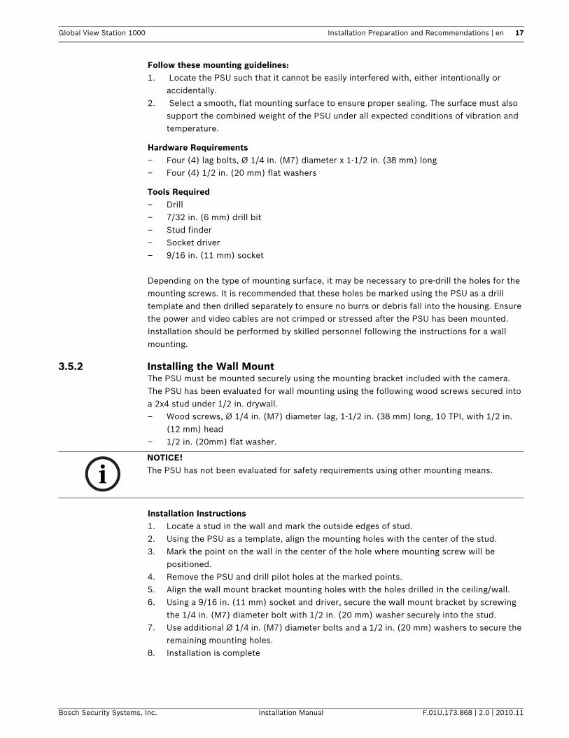
Follow these mounting guidelines:1. Locate the PSU such that it cannot be easily interfered with, either intentionally or
accidentally.2. Select a smooth, flat mounting surface to ensure proper sealing. The surface must also
support the combined weight of the PSU under all expected conditions of vibration and temperature.
Hardware Requirements– Four (4) lag bolts, Ø 1/4 in. (M7) diameter x 1-1/2 in. (38 mm) long– Four (4) 1/2 in. (20 mm) flat washers
Tools Required– Drill– 7/32 in. (6 mm) drill bit– Stud finder– Socket driver– 9/16 in. (11 mm) socket
Depending on the type of mounting surface, it may be necessary to pre-drill the holes for the mounting screws. It is recommended that these holes be marked using the PSU as a drill template and then drilled separately to ensure no burrs or debris fall into the housing. Ensure the power and video cables are not crimped or stressed after the PSU has been mounted. Installation should be performed by skilled personnel following the instructions for a wall mounting.
3.5.2 Installing the Wall MountThe PSU must be mounted securely using the mounting bracket included with the camera.The PSU has been evaluated for wall mounting using the following wood screws secured into a 2x4 stud under 1/2 in. drywall.– Wood screws, Ø 1/4 in. (M7) diameter lag, 1-1/2 in. (38 mm) long, 10 TPI, with 1/2 in.
(12 mm) head– 1/2 in. (20mm) flat washer.
Installation Instructions1. Locate a stud in the wall and mark the outside edges of stud.2. Using the PSU as a template, align the mounting holes with the center of the stud.3. Mark the point on the wall in the center of the hole where mounting screw will be
positioned.4. Remove the PSU and drill pilot holes at the marked points.5. Align the wall mount bracket mounting holes with the holes drilled in the ceiling/wall.6. Using a 9/16 in. (11 mm) socket and driver, secure the wall mount bracket by screwing
the 1/4 in. (M7) diameter bolt with 1/2 in. (20 mm) washer securely into the stud.7. Use additional Ø 1/4 in. (M7) diameter bolts and a 1/2 in. (20 mm) washers to secure the
remaining mounting holes.8. Installation is complete
NOTICE! The PSU has not been evaluated for safety requirements using other mounting means.
18 en | System Block Diagram Global View Station 1000
F.01U.173.868 | 2.0 | 2010.11 Installation Manual Bosch Security Systems, Inc.
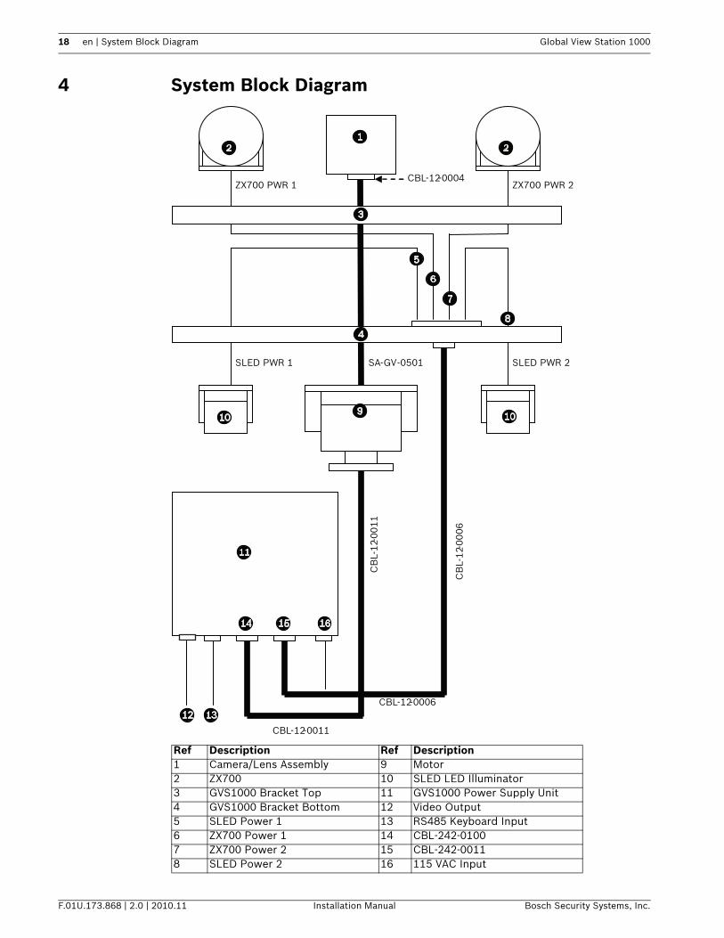
4 System Block Diagram
Ref Description Ref Description1 Camera/Lens Assembly 9 Motor2 ZX700 10 SLED LED Illuminator3 GVS1000 Bracket Top 11 GVS1000 Power Supply Unit4 GVS1000 Bracket Bottom 12 Video Output5 SLED Power 1 13 RS485 Keyboard Input6 ZX700 Power 1 14 CBL-242-01007 ZX700 Power 2 15 CBL-242-00118 SLED Power 2 16 115 VAC Input
ZX700 PWR 1 ZX700 PWR 2 CBL-12-0004
SLED PWR 2 SLED PWR 1
CBL-12-0011
CBL-12-0006
CB
L-1
2-00
06
CB
L-1
2-00
11
SA-GV-0501
Global View Station 1000 Installation | en 19
Bosch Security Systems, Inc. Installation Manual F.01U.173.868 | 2.0 | 2010.11
5 Installation
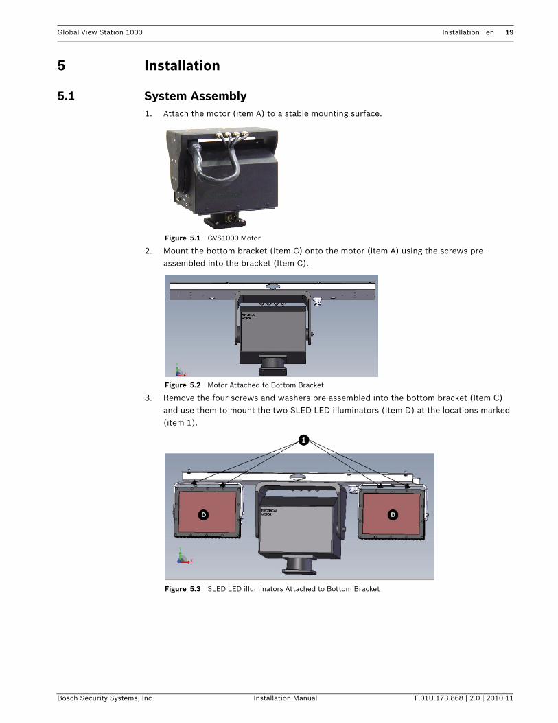
5.1 System Assembly1. Attach the motor (item A) to a stable mounting surface.
Figure 5.1 GVS1000 Motor
2. Mount the bottom bracket (item C) onto the motor (item A) using the screws pre-assembled into the bracket (Item C).
Figure 5.2 Motor Attached to Bottom Bracket
3. Remove the four screws and washers pre-assembled into the bottom bracket (Item C) and use them to mount the two SLED LED illuminators (Item D) at the locations marked (item 1).
Figure 5.3 SLED LED illuminators Attached to Bottom Bracket

20 en | Installation Global View Station 1000
F.01U.173.868 | 2.0 | 2010.11 Installation Manual Bosch Security Systems, Inc.
4. Mount the Camera sub-assembly (item E) to the top bracket (item B). At this point, See section 4.1.a. Turn item E over.b. Attach item B to item E using the screws, washers and spacers pre-assembled to the
bottom of the camera sub-assembly (Item E). When mounting, ensure the threaded pems are facing away from the assembly.
Figure 5.4 Camera Sub-assembly Connected to Top Bracket
5. Set the address of the system, as required, on the camera control board in the Camera Sub-Assembly (Item E). Refer to Section 5.2.3 Setting the System Address, page 24.
6. Connect the cable from the rear of the motor (Item B) to the bottom of the Camera Sub-Assembly (Item E) housing.
Figure 5.5 Motor Cable
Global View Station 1000 Installation | en 21
Bosch Security Systems, Inc. Installation Manual F.01U.173.868 | 2.0 | 2010.11
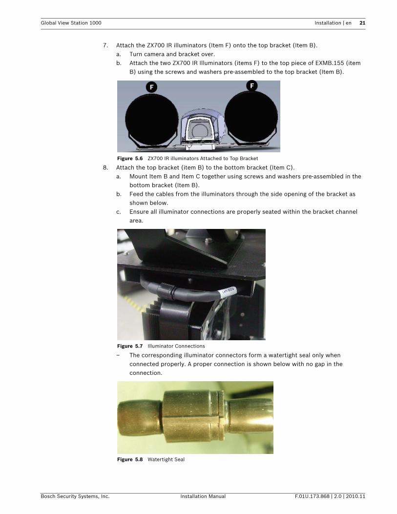
7. Attach the ZX700 IR illuminators (Item F) onto the top bracket (Item B).a. Turn camera and bracket over.b. Attach the two ZX700 IR Illuminators (items F) to the top piece of EXMB.155 (item
B) using the screws and washers pre-assembled to the top bracket (Item B).
Figure 5.6 ZX700 IR illuminators Attached to Top Bracket
8. Attach the top bracket (item B) to the bottom bracket (Item C).a. Mount Item B and Item C together using screws and washers pre-assembled in the
bottom bracket (Item B). b. Feed the cables from the illuminators through the side opening of the bracket as
shown below.c. Ensure all illuminator connections are properly seated within the bracket channel
area.
Figure 5.7 Illuminator Connections
– The corresponding illuminator connectors form a watertight seal only when connected properly. A proper connection is shown below with no gap in the connection.
Figure 5.8 Watertight Seal
22 en | Installation Global View Station 1000
F.01U.173.868 | 2.0 | 2010.11 Installation Manual Bosch Security Systems, Inc.
9. Attach the power supply unit cables.a. Connect System Cable CBL-12-0011 (Item H) from the PSU (item G) to the
connector at the bottom of the motor (item A).b. Connect Cable CBL-12-0006 from the PSU (item G) to the connector at the bottom
of the bracket (item C).
5.2 Commissioning and Installation
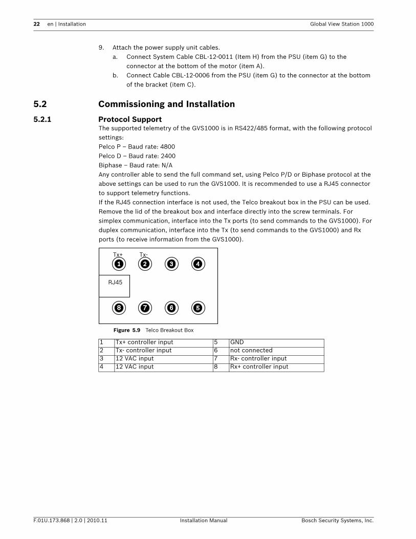
5.2.1 Protocol SupportThe supported telemetry of the GVS1000 is in RS422/485 format, with the following protocol settings: Pelco P – Baud rate: 4800Pelco D – Baud rate: 2400Biphase – Baud rate: N/AAny controller able to send the full command set, using Pelco P/D or Biphase protocol at the above settings can be used to run the GVS1000. It is recommended to use a RJ45 connector to support telemetry functions. If the RJ45 connection interface is not used, the Telco breakout box in the PSU can be used. Remove the lid of the breakout box and interface directly into the screw terminals. For simplex communication, interface into the Tx ports (to send commands to the GVS1000). For duplex communication, interface into the Tx (to send commands to the GVS1000) and Rx ports (to receive information from the GVS1000).
Figure 5.9 Telco Breakout Box
1 Tx+ controller input 5 GND2 Tx- controller input 6 not connected3 12 VAC input 7 Rx- controller input4 12 VAC input 8 Rx+ controller input
RJ45
Tx+ Tx-
Global View Station 1000 Installation | en 23
Bosch Security Systems, Inc. Installation Manual F.01U.173.868 | 2.0 | 2010.11
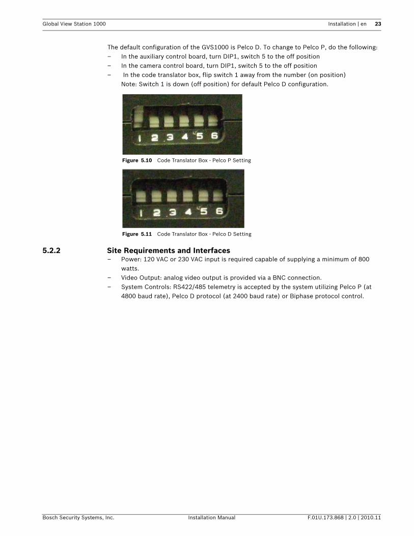
The default configuration of the GVS1000 is Pelco D. To change to Pelco P, do the following:– In the auxiliary control board, turn DIP1, switch 5 to the off position– In the camera control board, turn DIP1, switch 5 to the off position– In the code translator box, flip switch 1 away from the number (on position)
Note: Switch 1 is down (off position) for default Pelco D configuration.
Figure 5.10 Code Translator Box - Pelco P Setting
Figure 5.11 Code Translator Box - Pelco D Setting
5.2.2 Site Requirements and Interfaces– Power: 120 VAC or 230 VAC input is required capable of supplying a minimum of 800
watts.– Video Output: analog video output is provided via a BNC connection.– System Controls: RS422/485 telemetry is accepted by the system utilizing Pelco P (at
4800 baud rate), Pelco D protocol (at 2400 baud rate) or Biphase protocol control.
24 en | Installation Global View Station 1000
F.01U.173.868 | 2.0 | 2010.11 Installation Manual Bosch Security Systems, Inc.
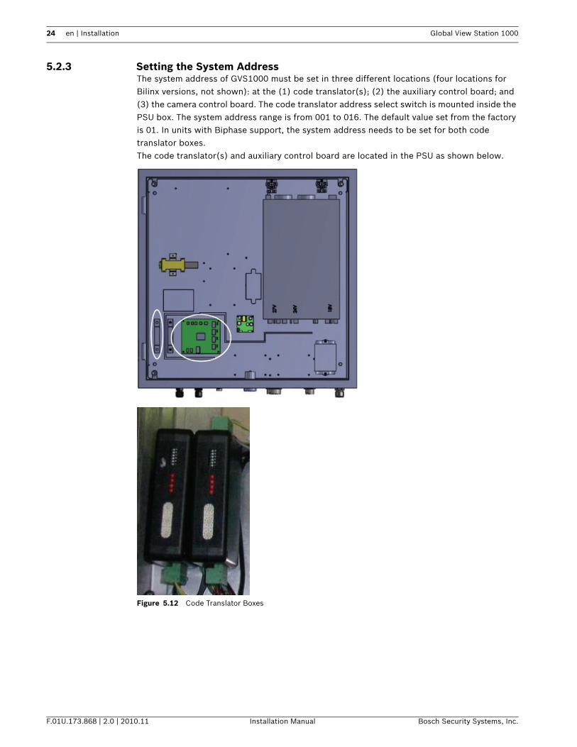
5.2.3 Setting the System AddressThe system address of GVS1000 must be set in three different locations (four locations for Bilinx versions, not shown): at the (1) code translator(s); (2) the auxiliary control board; and (3) the camera control board. The code translator address select switch is mounted inside the PSU box. The system address range is from 001 to 016. The default value set from the factory is 01. In units with Biphase support, the system address needs to be set for both code translator boxes.The code translator(s) and auxiliary control board are located in the PSU as shown below.
Figure 5.12 Code Translator Boxes
Global View Station 1000 Installation | en 25
Bosch Security Systems, Inc. Installation Manual F.01U.173.868 | 2.0 | 2010.11
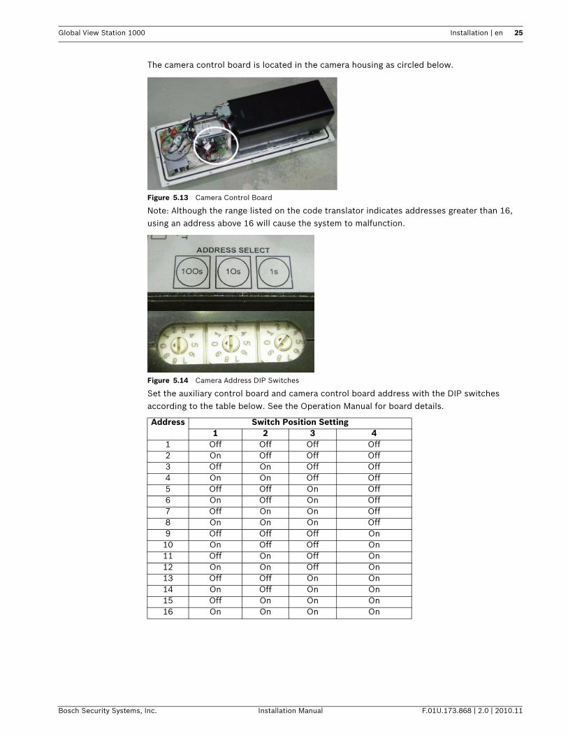
The camera control board is located in the camera housing as circled below.
Figure 5.13 Camera Control Board
Note: Although the range listed on the code translator indicates addresses greater than 16, using an address above 16 will cause the system to malfunction.
Figure 5.14 Camera Address DIP Switches
Set the auxiliary control board and camera control board address with the DIP switches according to the table below. See the Operation Manual for board details.
Address Switch Position Setting1 2 3 4
1 Off Off Off Off2 On Off Off Off3 Off On Off Off4 On On Off Off5 Off Off On Off6 On Off On Off7 Off On On Off8 On On On Off9 Off Off Off On10 On Off Off On11 Off On Off On12 On On Off On13 Off Off On On14 On Off On On15 Off On On On16 On On On On
26 en | Installation Global View Station 1000
F.01U.173.868 | 2.0 | 2010.11 Installation Manual Bosch Security Systems, Inc.
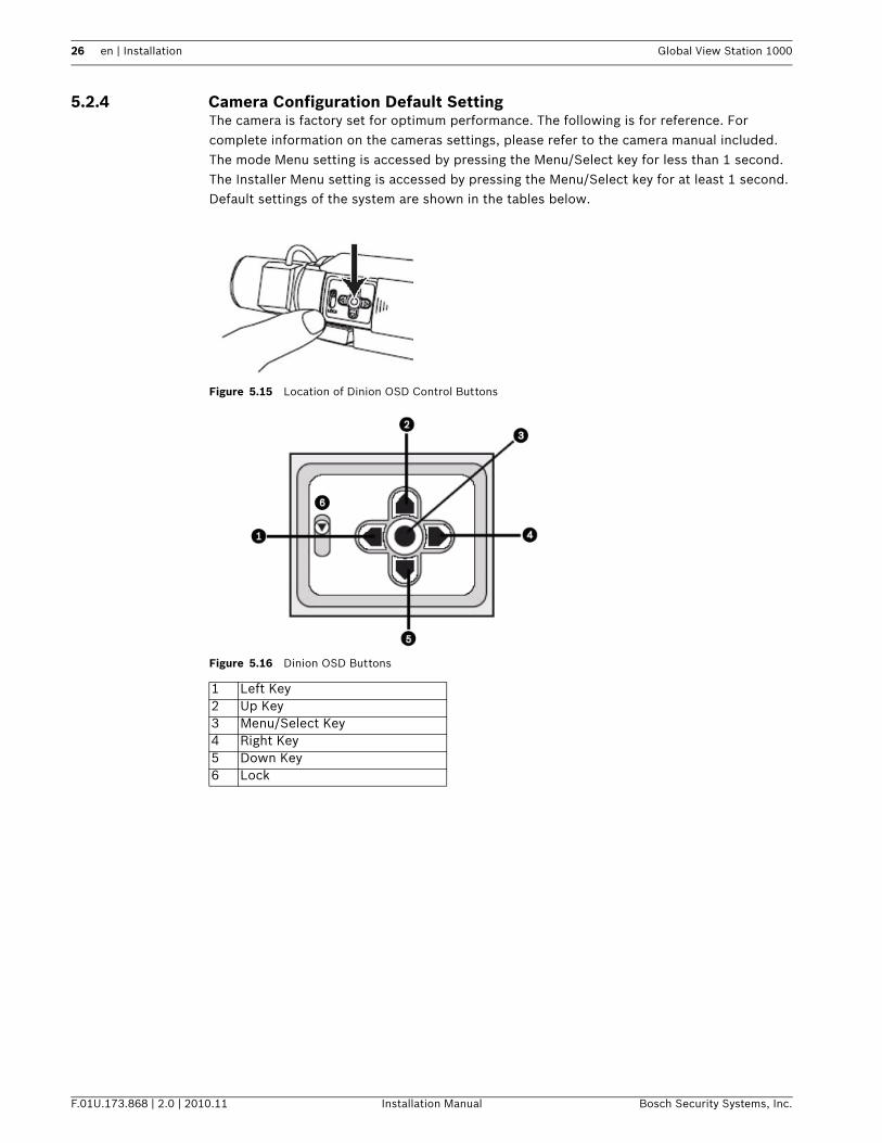
5.2.4 Camera Configuration Default SettingThe camera is factory set for optimum performance. The following is for reference. For complete information on the cameras settings, please refer to the camera manual included.The mode Menu setting is accessed by pressing the Menu/Select key for less than 1 second. The Installer Menu setting is accessed by pressing the Menu/Select key for at least 1 second. Default settings of the system are shown in the tables below.
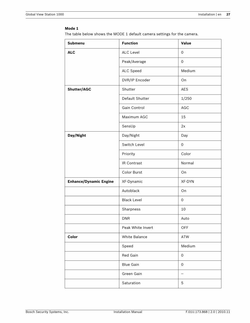
Figure 5.15 Location of Dinion OSD Control Buttons
Figure 5.16 Dinion OSD Buttons
1 Left Key2 Up Key3 Menu/Select Key4 Right Key5 Down Key6 Lock
Global View Station 1000 Installation | en 27
Bosch Security Systems, Inc. Installation Manual F.01U.173.868 | 2.0 | 2010.11
Mode 1The table below shows the MODE 1 default camera settings for the camera.
Submenu Function Value
ALC ALC Level 0
Peak/Average 0
ALC Speed Medium
DVR/IP Encoder On
Shutter/AGC Shutter AES
Default Shutter 1/250
Gain Control AGC
Maximum AGC 15
SensUp 2x
Day/Night Day/Night Day
Switch Level 0
Priority Color
IR Contrast Normal
Color Burst On
Enhance/Dynamic Engine XF-Dynamic XF-DYN
Autoblack On
Black Level 0
Sharpness 10
DNR Auto
Peak White Invert OFF
Color White Balance ATW
Speed Medium
Red Gain 0
Blue Gain 0
Green Gain --
Saturation 5
28 en | Installation Global View Station 1000
F.01U.173.868 | 2.0 | 2010.11 Installation Manual Bosch Security Systems, Inc.
Installer MenuThe table below shows the Installer Menu default camera settings for the camera.
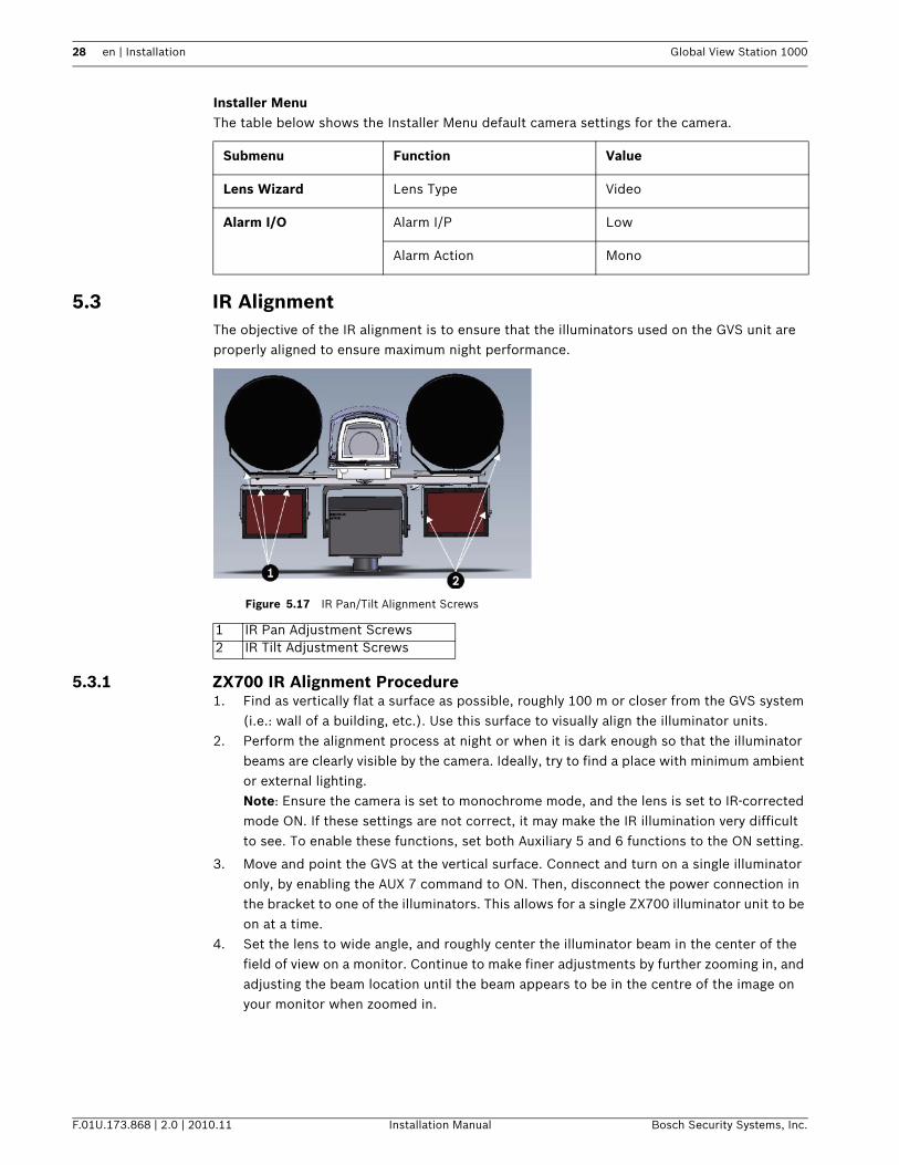
5.3 IR AlignmentThe objective of the IR alignment is to ensure that the illuminators used on the GVS unit are properly aligned to ensure maximum night performance.
Figure 5.17 IR Pan/Tilt Alignment Screws
5.3.1 ZX700 IR Alignment Procedure1. Find as vertically flat a surface as possible, roughly 100 m or closer from the GVS system
(i.e.: wall of a building, etc.). Use this surface to visually align the illuminator units. 2. Perform the alignment process at night or when it is dark enough so that the illuminator
beams are clearly visible by the camera. Ideally, try to find a place with minimum ambient or external lighting.Note: Ensure the camera is set to monochrome mode, and the lens is set to IR-corrected mode ON. If these settings are not correct, it may make the IR illumination very difficult to see. To enable these functions, set both Auxiliary 5 and 6 functions to the ON setting.
3. Move and point the GVS at the vertical surface. Connect and turn on a single illuminator only, by enabling the AUX 7 command to ON. Then, disconnect the power connection in the bracket to one of the illuminators. This allows for a single ZX700 illuminator unit to be on at a time.
4. Set the lens to wide angle, and roughly center the illuminator beam in the center of the field of view on a monitor. Continue to make finer adjustments by further zooming in, and adjusting the beam location until the beam appears to be in the centre of the image on your monitor when zoomed in.
Submenu Function Value
Lens Wizard Lens Type Video
Alarm I/O Alarm I/P Low
Alarm Action Mono
1 IR Pan Adjustment Screws2 IR Tilt Adjustment Screws
Global View Station 1000 Installation | en 29
Bosch Security Systems, Inc. Installation Manual F.01U.173.868 | 2.0 | 2010.11
5. Once the beam is centered on the monitor, turn off the illuminator. Perform the same steps to align the second illuminator unit.
6. Once each illuminator is individually aligned, the beams of the illuminators should overlap when looking at your monitor. If not, make sure to repeat the preceding steps to ensure the illuminators are properly aligned within the field of view and that their beams overlap on your monitor.
7. When properly aligned, the beams from each illuminator should appear on the monitor as a single illuminated area, and are aligned to the maximum rated distance.
5.3.2 SLED IR Alignment1. Set the lens to the maximum wide angle setting.2. Align each illuminator so that each illuminator covers the entire field of view.3. Ensure both illuminators overlap as described above.
30 en | Specifications Global View Station 1000
F.01U.173.868 | 2.0 | 2010.11 Installation Manual Bosch Security Systems, Inc.
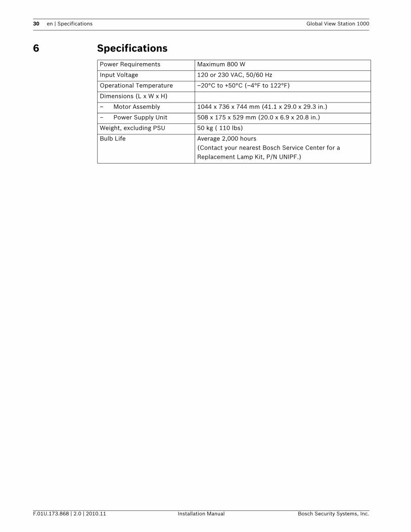
6 SpecificationsPower Requirements Maximum 800 W
Input Voltage 120 or 230 VAC, 50/60 Hz
Operational Temperature –20°C to +50°C (–4°F to 122°F)
Dimensions (L x W x H)
– Motor Assembly 1044 x 736 x 744 mm (41.1 x 29.0 x 29.3 in.)
– Power Supply Unit 508 x 175 x 529 mm (20.0 x 6.9 x 20.8 in.)
Weight, excluding PSU 50 kg ( 110 lbs)
Bulb Life Average 2,000 hours(Contact your nearest Bosch Service Center for a Replacement Lamp Kit, P/N UNIPF.)

Bosch Security Systems, Inc.
www.boschsecurity.com© Bosch Security Systems, Inc., 2010