Embed Size (px)
Citation preview
GLview Pro 6.4
User Guide 1
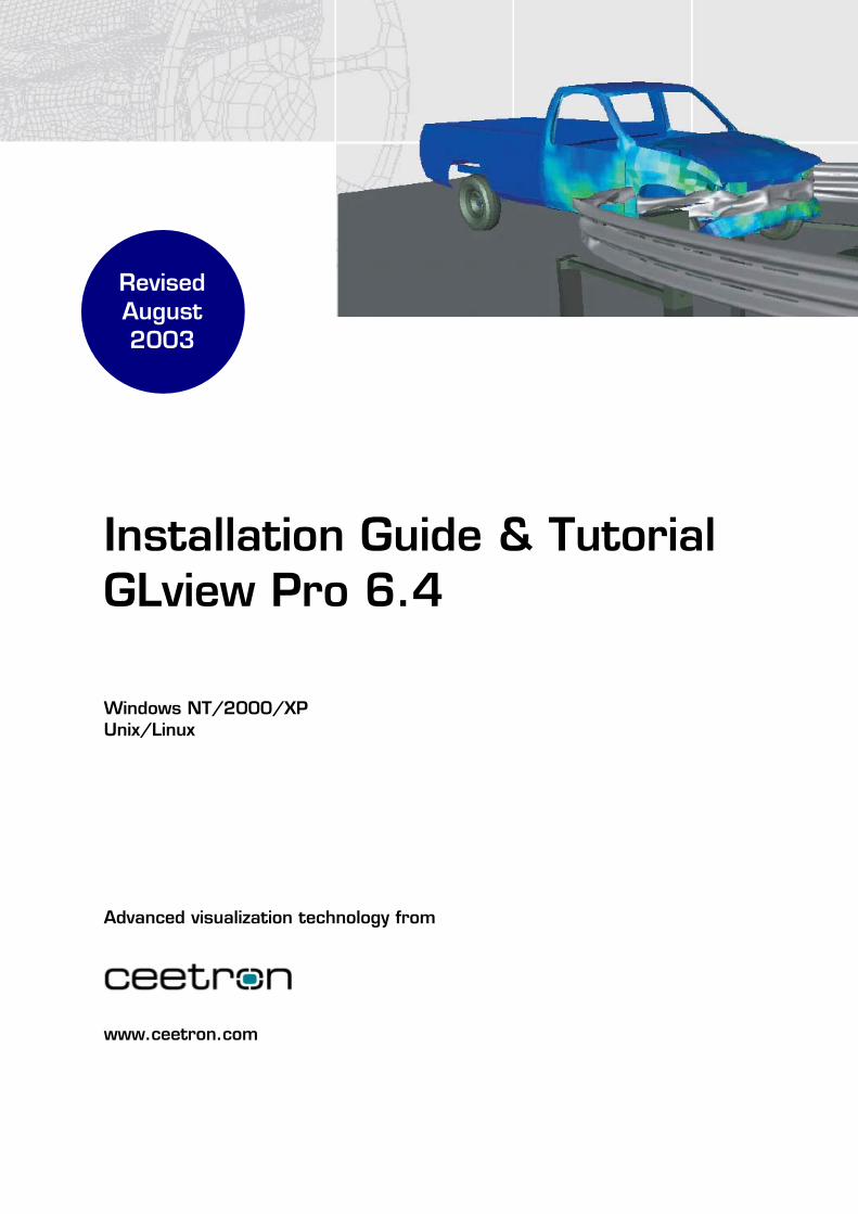
Installation Guide & Tutorial GLview Pro 6.4 Windows NT/2000/XP Unix/Linux
Advanced visualization technology from
www.ceetron.com
Revised August 2003
GLview Pro 6.4
User Guide 2
Table of contents
1 Introduction.............................................................................................................................................. 4 GLview end-user products ....................................................................................................................... 4 GLview developer products ..................................................................................................................... 4
2 Installation guide...................................................................................................................................... 5 Contents of distribution ............................................................................................................................ 5 Supported operating systems.................................................................................................................... 5 Installation instructions on UNIX............................................................................................................. 5 Troubleshooting........................................................................................................................................ 6
3 GLview Pro main overview ..................................................................................................................... 8 Basic operations ....................................................................................................................................... 8 Program features....................................................................................................................................... 9 Export to VTF files for GLview Express and GLview 3D Plug-in .......................................................... 9
4 Getting started........................................................................................................................................ 12 Introduction ............................................................................................................................................ 12 Tutorial 1: Main program features.......................................................................................................... 13 Tutorial 2: Advanced features ................................................................................................................ 15
5 Tips and hints ......................................................................................................................................... 18 Menus and user interface........................................................................................................................ 18 Using GLview Pro without hardware graphics ...................................................................................... 19
6 Commands .............................................................................................................................................. 20 Command line options............................................................................................................................ 20 Commands.............................................................................................................................................. 20
7 FEA file readers...................................................................................................................................... 21 Import filters for commercial codes ....................................................................................................... 21 Import filters for GLview internal file formats....................................................................................... 21
GLview Pro 6.4
User Guide 3
Copyright © 2003 Ceetron ASA
For information, please contact:
Ceetron ASA P.O. Box 1247 Pirsenteret N-7462 Trondheim, Norway. www.ceetron.com
Tel: +47 73 54 61 50 Fax: +47 73 54 61 44 E-mail: [email protected] [email protected] [email protected]
Trademarks
GLview is a registered trademark of Ceetron ASA in Norway and a trademark in other countries. Microsoft, Windows, and the Windows logo are trademarks or registered trademarks of Microsoft Corporation. OpenGL, IRIX, SGI and Silicon Graphics are trademarks or registered trademarks of Silicon Graphics, Inc. UNIX is a registered trademark in the United States and other countries, licensed exclusively through X/Open Company Limited. Sun and Solaris are trademarks or registered trademarks of Sun Microsystems, Inc. in the United States and other countries. Compaq, Digital, HP, DEC OSF/1, HP-UX and Tru64 are trademarks or registered trademarks of Hewlett-Packard Company. IBM and AIX are registered trademarks of IBM Corporation. X Window System is a product of the Massachusetts Institute of Technology.
Other brands and product names are trademarks of their respective owners.
Ceetron believes the information in this leaflet is accurate as of its publication date. The information is subject to change without notice and is subject to applicable technical product descriptions.
Trondheim, Norway, August 2003
GLview Pro 6.4
User Guide 4
1 Introduction GLview end-user products
GLview Pro
GLview Pro is a powerful post-processor for interactive 3D visualization and animation of results from engineering applications. It can export results to the GLview Express file format and it supports ABAQUS, ANSYS, FEMAP, I-DEAS, LS-DYNA, MSC.Marc, MSC.Nastran, NE/Nastran, and RADIOSS. Available on Windows, Linux, and Unix.
GLview Express (free)
GLview Express is a free add-on stand alone application to GLview Pro. GLview Express reads data sets generated by GLview Pro and can be distributed to customers and clients. The product is ideal for interactive presentations of technical results. Available on Windows and Unix.
GLview 3D Plug-in (free)
The GLview 3D Plug-in is a free add-on plug-in to the GLview environment for presentation of real element models and results. It enables you to present your 3D analysis models interactively in a PowerPoint Presentation and in Internet Explorer. Available on Windows.
GLview developer products
GLview Visualization API
GLview Visualization API is a C++ object-oriented application-programming interface for develpment of 3D visualization software. It allows the developer to utilize all of GLview Pro's advanced features and rendering techniques and integrate it into another program environment. Available on Windows and Unix.
GLview Express Writer
The GLview Express Writer enables developers of commercial and in-house FEA codes to utilize the free presentation tools GLview Express and GLview 3D Plug-in. By using these products, FEA data can easily be shared across different HW and SW platforms without the need of installing licensed software.
By using GLview Express, the FEA model and results can easily be shared with colleagues, suppliers, partners, and management for review or for further analysis. With the use of GLview 3D Plug-in, the 3D FEA data can be viewed interactively in PowerPoint or Internet Explorer.
Geometry models, result selections, animation settings, and various output options (e.g. draw modes wire frame, points, surfaces) can be conveyed to GLview Express and GLview 3D Plug-in by means of a VTF file. The VTF file format preserves all FEA characteristics such as node and element numbering, element topology, and the original numerical result values.
The VTF file can be distributed to colleagues, sub suppliers, partners, and management for review. Moreover, the VTF file can be read by the full blown post-processor GLview Pro for further interpretation and analysis.
GLview Pro 6.4
User Guide 5
2 Installation guide Contents of distribution
A commercial version of GLview Pro contains the following items:
User Guide (on paper and as .pdf document)
License and Maintenance Agreement
Installation CD:
• GLview Pro executables: UNIX (SGI, Digital, Sun, HP, IBM, Linux) Windows NT/2000/XP
• FEA import filters for commercial solvers, please refer to Chapter 7: MOVIE.BYU (ASCII and binary) VTF (ASCII and binary)
• GLview Pro online help
• Demonstration and tutorial data sets
Supported operating systems
Windows NT/2000/XP SGI IRIX 6.x Compaq Tru64, Digital OSF/1 4.0. OpenGL operating system option is required. Sun Solaris 2.7 with OpenGL option installed (OpenGL hardware is optional). HP HP-UX 10.20. VISUALIZE FX2/4/6 card and an operating systems extension is required. IBM RS/6000 AIX 4.3 with OpenGL option installed. Linux kernel 2.4.18-3 or later, GNU GCC runtime environment version 2.96 or later, and XFree86 4.1.0 (for OpenGL).
Installation instructions on UNIX
The GLview Pro installation on UNIX is available in two versions; GLview and XGLview.
GLview Pro requires OpenGL, the X-version does not require any specific hardware and may be run locally on any machine or remotely from another machine (e.g. a network server). Run the OpenGL version whenever possible.
OpenGL can be installed as an operating system extension on all UNIX platforms supported by GLview. Some UNIX platforms also require an OpenGL supported graphics card to be installed (software emulation not possible). Contact your system administrator or hardware provider for further details.
The following files are included in the distribution:
glv_irix.tar: SiliconGraphics IRIX 6.x glv_osf1.tar: Digital UNIX (OSF/1) 4.0 glv_sun.tar: Sun Solaris 2.7 glv_hpux.tar: HP HP-UX 10.20 glv_aix.tar: IBM RS/6000 AIX 4.x glv_lin.tar: Linux kernel 2.4.18-3
models.tar: 4 demonstration models and 2 tutorial data sets.
Make sure that the GLview Pro CDROM is inserted, and that the CDROM player has been mounted correctly. In the below instructions, it is assumed that the mount point is /CDROM. If this is not the case, please change accordingly.
Change to the directory where you want GLview Pro to be installed.
GLview Pro 6.4
User Guide 6
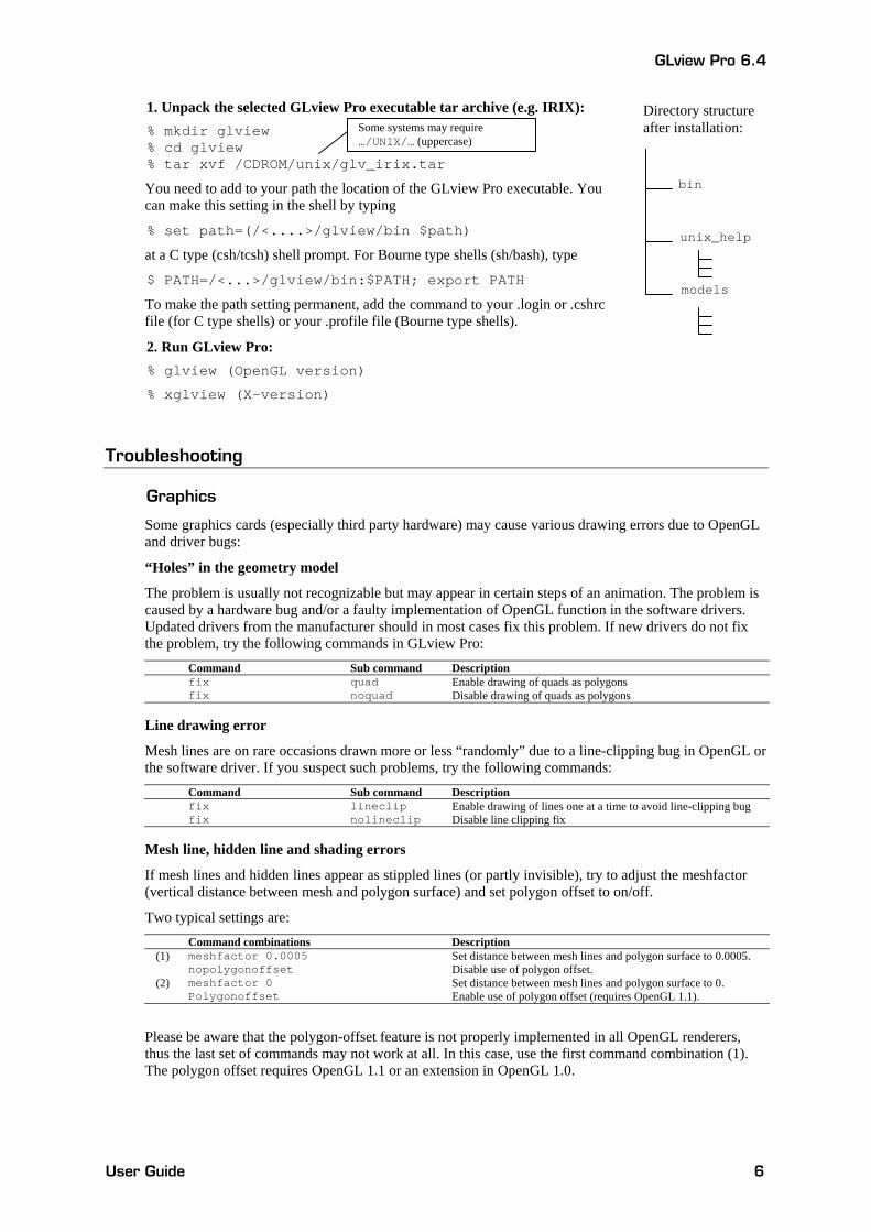
1. Unpack the selected GLview Pro executable tar archive (e.g. IRIX): % mkdir glview % cd glview % tar xvf /CDROM/unix/glv_irix.tar
You need to add to your path the location of the GLview Pro executable. You can make this setting in the shell by typing
% set path=(/<....>/glview/bin $path)
at a C type (csh/tcsh) shell prompt. For Bourne type shells (sh/bash), type
$ PATH=/<...>/glview/bin:$PATH; export PATH
To make the path setting permanent, add the command to your .login or .cshrc file (for C type shells) or your .profile file (Bourne type shells).
2. Run GLview Pro: % glview (OpenGL version)
% xglview (X-version)
Troubleshooting
Graphics
Some graphics cards (especially third party hardware) may cause various drawing errors due to OpenGL and driver bugs:
“Holes” in the geometry model
The problem is usually not recognizable but may appear in certain steps of an animation. The problem is caused by a hardware bug and/or a faulty implementation of OpenGL function in the software drivers. Updated drivers from the manufacturer should in most cases fix this problem. If new drivers do not fix the problem, try the following commands in GLview Pro:
Command Sub command Description fix quad Enable drawing of quads as polygons fix noquad Disable drawing of quads as polygons
Line drawing error
Mesh lines are on rare occasions drawn more or less “randomly” due to a line-clipping bug in OpenGL or the software driver. If you suspect such problems, try the following commands:
Command Sub command Description fix lineclip Enable drawing of lines one at a time to avoid line-clipping bug fix nolineclip Disable line clipping fix
Mesh line, hidden line and shading errors
If mesh lines and hidden lines appear as stippled lines (or partly invisible), try to adjust the meshfactor (vertical distance between mesh and polygon surface) and set polygon offset to on/off.
Two typical settings are: Command combinations Description
(1) meshfactor 0.0005 Set distance between mesh lines and polygon surface to 0.0005. nopolygonoffset Disable use of polygon offset.
(2) meshfactor 0 Set distance between mesh lines and polygon surface to 0. Polygonoffset Enable use of polygon offset (requires OpenGL 1.1).
Please be aware that the polygon-offset feature is not properly implemented in all OpenGL renderers, thus the last set of commands may not work at all. In this case, use the first command combination (1). The polygon offset requires OpenGL 1.1 or an extension in OpenGL 1.0.
Directory structure after installation:
bin
unix_help
models
Some systems may require …/UNIX/… (uppercase)
GLview Pro 6.4
User Guide 7
License key and permissions
Entering new license key
If you are unable to enter the license information, the most likely problem is that you do not have permissions to write to the GLview Pro program directory.
The license key resides in the glview.glk file. If you still cannot change the license code, you may edit the file directly and type in the key provided by Ceetron.
Example of file content: 12018433-CIUH-12331-GGED-CDPPEGBUPO
User name
Number of users exceeded
GLview Pro performs license check on the local area network. If the message “Number of current users exceeds number of allowed simultaneous users for this GLview license”, more users than the available number of registered licenses are used at the same time. The license key is issued as a floating license with a maximum number of users that is defined in the license key.
Dongle problems
If you have a dongled version of GLview Pro, please refer to the separate troubleshooting sheet included in the installation package.
Problems with file associations
When running GLview Pro for the first time, a number of file extensions are automatically associated with the program. If several glview.exe files are installed on the computer, the forceregisterfiles command will automatically associate these files with the currently running GLview Pro
GLview Pro 6.4
User Guide 8
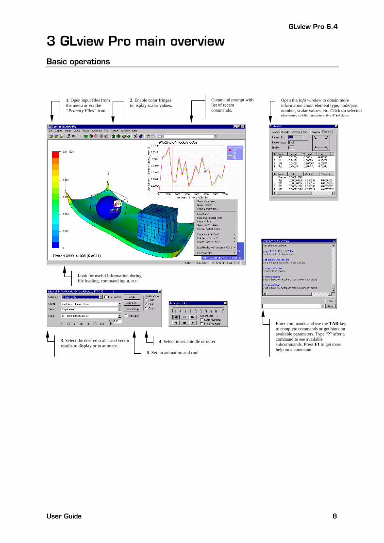
3 GLview Pro main overview Basic operations
1. Open input files from the menu or via the “Primary Files” icon.
2. Enable color fringes to isplay scalar values.
Command prompt with list of recent commands.
Open the Info window to obtain more information about element type, node/part number, scalar values, etc. Click on selected elements while pressing the Ctrl-key
Look for useful information during file loading, command input, etc.
3. Select the desired scalar and vector results to display or to animate. 5. Set up animation and run!
4. Select inner, middle or outer
Enter commands and use the TAB-key to complete commands or get hints on available parameters. Type “?” after a command to see available subcommands. Press F1 to get more help on a command.
GLview Pro 6.4
User Guide 9
Program features
GLview Pro is an effective and compact 3D visualization program handling large quantities of results data. Data originating from applications within structural mechanics, marine hydro dynamics, fluid dynamics, and other scientific analysis, can be animated interactively if time-dependent results are available. FEA APPLICATION SUPPORT • Direct file readers for commercial solvers
(please refer to Chapter 7 for a complete list) • Support for separated geometry and results files USER INTERFACE • Intuitive, easy-to-use graphical user interface • Flexible command and scripting language • On-line documentation • Drag & drop files with auto-detect functionality • Advanced picking and elaborate feedback of information on
the model, results, part/material, and element properties INTERFACES, IMPORT/EXPORT • Generic file format import/export: VTF and MOVIE.BYU • Output of images to BMP, TIF, IRIS RGB, PostScript
(bitmap), PPM, and output to VRML 1 and 2 • Generation of MPEG, AVI, and animated GIF • Generation of VTF files for GLview Express and 3D Plug-in • Export of 2D plot data to file • Import of custom plot data • Printing of 2D plot or 3D scene • Direct HTML-export to Internet Explorer INTERACTIVE ANIMATION • Time domain and frequency domain (mode shape) animation
of scalars, vectors, and displacements • Particle trace and cutting plane animation • Viewpoint animation • Real-time manipulation of models during animation • Interpolation between time steps during animation FEATURES • Display of scalar and vector results • 2D plotting of nodal/element results • 2D plotting of scalar results along user defined lines • Trace lines of vector results (node tracing) • Extraction of element results through picking • Rigid body transformations • Advanced mirroring options with multiple planes • Contour and legend control • Logging of commands • Scaling of model
ELEMENTS AND DATA SUPPORT • Beams, triangles, quads, tetrahedrons, hexahedrons,
pentahedrons, pyramids • Eroded elements • Adaptive meshes • Unstructured grids • Nodal and element results RESULTS DISPLAY OPTIONS • Polygon viewing by surfaces, lines, and points • Outline, hidden line, outline mesh, overlaid mesh • Filled contours (textured, plain, or shaded) • Contour lines • Vector arrows (with fringe colors) and damping of vectors • Multiple particle traces of volumetric data results • Multiple cutting planes • Iso surface RENDERING • High performance graphics suited for animation of large
models • Software and hardware rendering support using OpenGL • Set optional point of rotation • Perspective/orthographic projection • Shading, flat and smooth shading (Gouraud shading) • Lighting, arbitrary colors, multiple light sources and
directions • Texture and environment mapping • Anti-aliased lines • Set transparent surfaces independently for each part
Export to VTF files for GLview Express and GLview 3D Plug-in
GLview Express and GLview 3D Plug-in can be downloaded for free at www.ceetron.com!
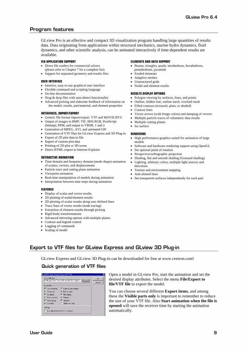
Quick generation of VTF files
Open a model in GLview Pro, start the animation and set the desired display attributes. Select the menu File/Export to file/VTF file to export the model.
You can choose several different Export items, and among these the Visible parts only is important to remember to reduce the size of your VTF file. Also Start animation when the file is opened will save the receiver time by starting the animation automatically.
GLview Pro 6.4
User Guide 10
Generation of VTF files (detailed)
To generate a VTF file you must have GLview Pro installed. Load the results database, select scalar/vector results, select a number of steps to animate and load the animation. Set the desired display attributes (e.g. fringes, displacements, colors, and eye point) and export the current animation to a VTF file. The file is now ready for GLview Express and GLview 3D Plug-in.
If the initial results database is very large, you should not worry too much about the final file size of the VTF file since GLview Pro extracts only the geometry, one scalar and one vector result. Despite the smaller file size, element information or the results will not be manipulated or reduced in any way!
Distribution of results
The VTF files are usually of a size that allows e-mail and FTP distribution. Compress the files in a zip-archive, send the files and have the other party unpack the files and install GLview Express. 2 minutes and the animations should be running!
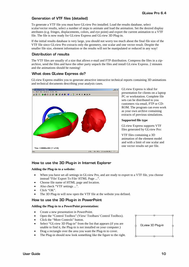
What does GLview Express do?
GLview Express enables you to generate attractive interactive technical reports containing 3D animations and technical documents describing your analysis cases.
GLview Express is ideal for presentation for clients on a laptop PC or workstation. Complete file sets can be distributed to you customers via email, FTP or CD-ROM. The program can even work as your own archive containing extracts of previous simulations.
Supported file type
GLview Express supports VTF files generated by GLview Pro:
VTF files containing a 3D animation of the element model and with a limit of one scalar and one vector results set per file.
How to use the 3D Plug-in in Internet Explorer
Adding the Plug-in to a website:
• When you have set all settings in GLview Pro, and are ready to export to a VTF file, you choose instead “File/ Export To File/ HTML Page ...”.
• Choose file name of HTML page and location. • Also check “VTF settings ...”. • Click “OK”. • The 3D Plug-in will now open the VTF file at the website you defined.
How to use the 3D Plug-in in PowerPoint
Adding the Plug-in to a PowerPoint presentation:
• Create a new presentation in PowerPoint. • Open the “Control Toolbox” (View/ Toolbars/ Control Toolbox). • Click the “More Controls” button. • Select “GLview 3D Plug-in” from the list that appears (if you are
unable to find it, the Plug-in is not installed on your computer.) • Drag a rectangle over the area you want the Plug-in to cover. • The Plug-in should now look something like the figure to the right.
GLview Pro 6.4
User Guide 11
Using and Customizing the Plug-in
When you have added the Plug-in to your slide, you may start setting its properties and add buttons to load VTF files into the Plug-in. There are two ways to make the Plug-in load VTF files:
• FileURL property (Easy Usage)
• Open ( ) method (Advanced Usage)
Easy Usage of the Plug-in using the FileURL property
If you right-click the Plug-in and select “Properties”, you will get its property window.
Write the name of a VTF file for the FileURL property, and close the property window.
View the slide show. The Plug-in will now open the VTF file immediately when the sheet/ slide containing the Plug-in appears!
Advanced Usage of the Plug-in using the Open ( ) method
The Plug-in has a method called Open ( ). This method takes a filename as argument, and opens it if it is a VTF file.
You have to specify an action that causes the Open ( ) method to be executed. The most obvious way to do this is to add a button to the slide, and implement this button’s OnClick ( ) method, which is executed when the button is clicked.
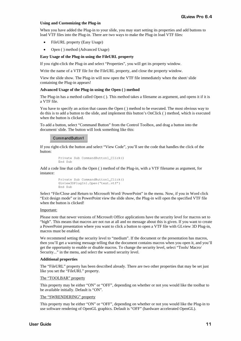
To add a button, select “Command Button” from the Control Toolbox, and drag a button into the document/ slide. The button will look something like this:
If you right-click the button and select “View Code”, you’ll see the code that handles the click of the button: Private Sub CommandButton1_Click() End Sub
Add a code line that calls the Open ( ) method of the Plug-in, with a VTF filename as argument, for instance: Private Sub CommandButton1_Click() GLview3DPlugIn1.Open(“test.vtf”) End Sub
Select “File/Close and Return to Microsoft Word/ PowerPoint” in the menu. Now, if you in Word click “Exit design mode” or in PowerPoint view the slide show, the Plug-in will open the specified VTF file when the button is clicked!
Important:
Please note that newer versions of Microsoft Office applications have the security level for macros set to “high”. This means that macros are not run at all and no message about this is given. If you want to create a PowerPoint presentation where you want to click a button to open a VTF file with GLview 3D Plug-in, macros must be enabled.
We recommend setting the security level to “medium”. If the document or the presentation has macros, then you’ll get a warning message telling that the document contains macros when you open it, and you’ll get the opportunity to enable or disable macros. To change the security level, select “Tools/ Macro/ Security...” in the menu, and select the wanted security level.
Additional properties
The “FileURL” property has been described already. There are two other properties that may be set just like you set the “FileURL” property.
The “TOOLBAR” property
This property may be either “ON” or “OFF”, depending on whether or not you would like the toolbar to be available initially. Default is “ON”.
The “SWRENDERING” property
This property may be either “ON” or “OFF”, depending on whether or not you would like the Plug-in to use software rendering of OpenGL graphics. Default is “OFF” (hardware accelerated OpenGL).
GLview Pro 6.4
User Guide 12
4 Getting started Introduction
This chapter provides an instructional tour through GLview Pro by highlighting some key features. A large number of additional commands, functions and settings are available and is listed in the online help.
For useful hints when using GLview Pro, please see Chapter 5 for tips and hints.
Tutorial examples
• Tutorial 1: MOVIE.BYU files. Cyclic deformation of a pipe. 16 steps.
• Tutorial 2: LS-DYNA d3plot files. Two objects are hitting a plate. 73 steps.
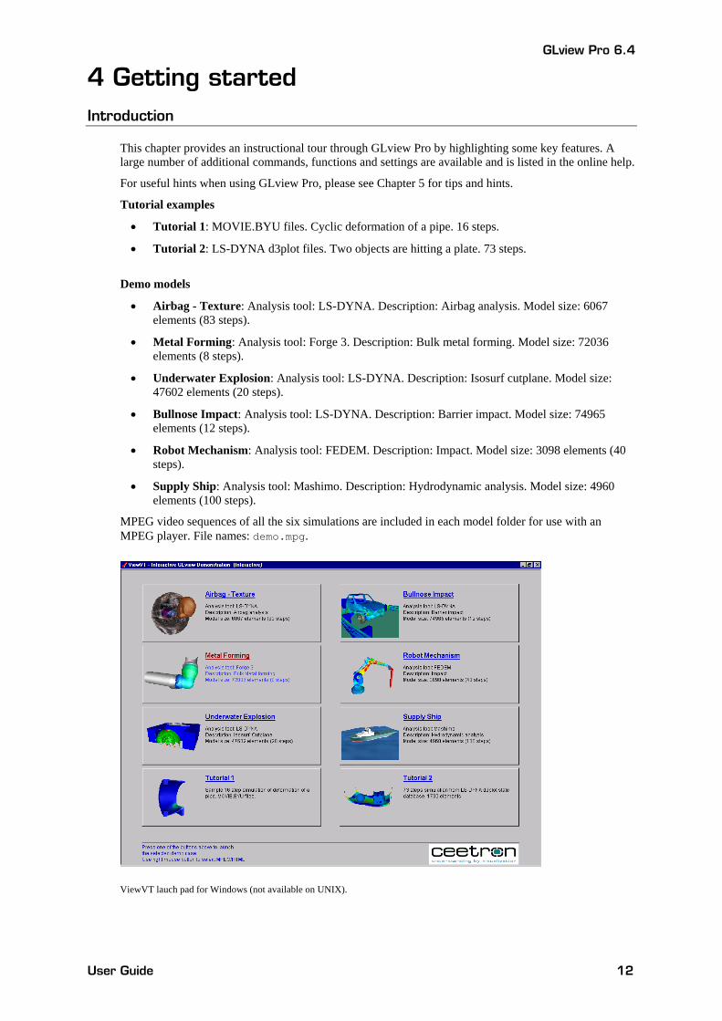
Demo models
• Airbag - Texture: Analysis tool: LS-DYNA. Description: Airbag analysis. Model size: 6067 elements (83 steps).
• Metal Forming: Analysis tool: Forge 3. Description: Bulk metal forming. Model size: 72036 elements (8 steps).
• Underwater Explosion: Analysis tool: LS-DYNA. Description: Isosurf cutplane. Model size: 47602 elements (20 steps).
• Bullnose Impact: Analysis tool: LS-DYNA. Description: Barrier impact. Model size: 74965 elements (12 steps).
• Robot Mechanism: Analysis tool: FEDEM. Description: Impact. Model size: 3098 elements (40 steps).
• Supply Ship: Analysis tool: Mashimo. Description: Hydrodynamic analysis. Model size: 4960 elements (100 steps).
MPEG video sequences of all the six simulations are included in each model folder for use with an MPEG player. File names: demo.mpg.
ViewVT lauch pad for Windows (not available on UNIX).
GLview Pro 6.4
User Guide 13
Tutorial 1: Main program features
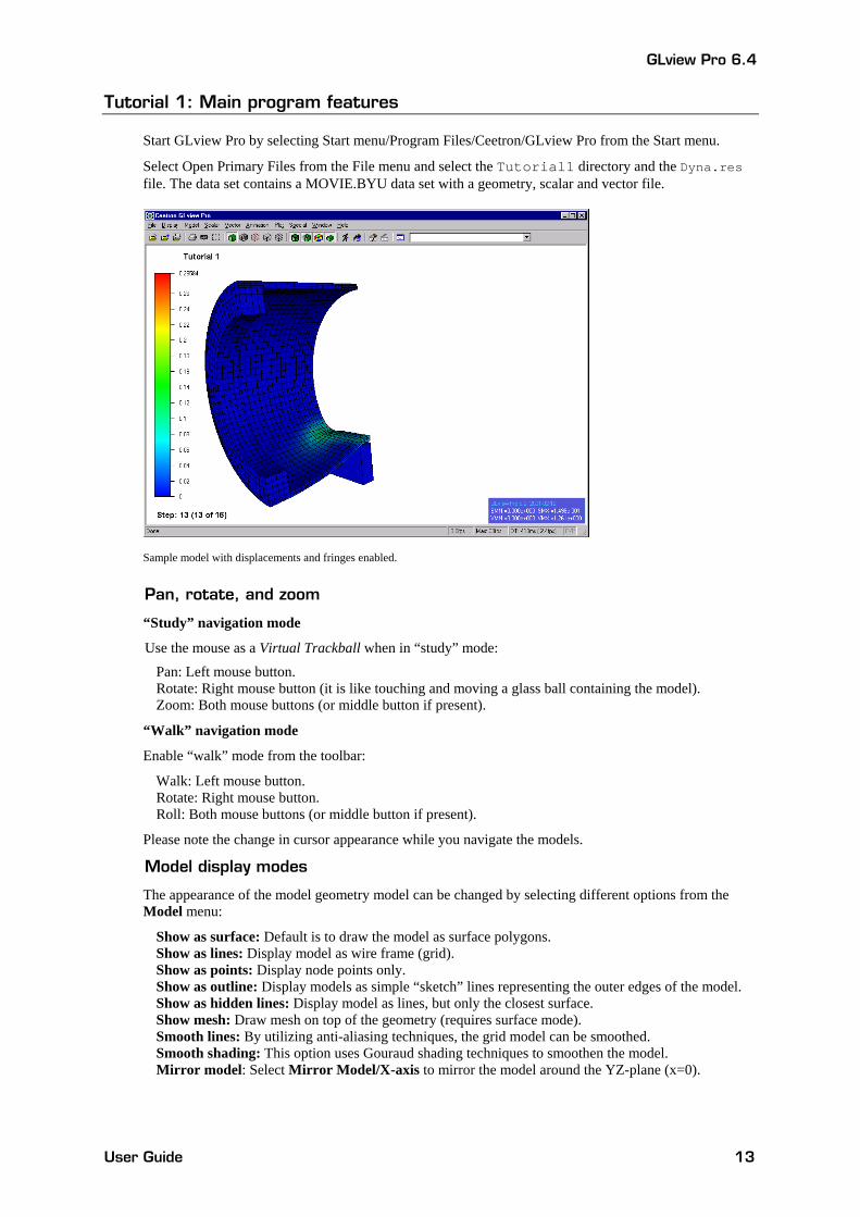
Start GLview Pro by selecting Start menu/Program Files/Ceetron/GLview Pro from the Start menu.
Select Open Primary Files from the File menu and select the Tutorial1 directory and the Dyna.res file. The data set contains a MOVIE.BYU data set with a geometry, scalar and vector file.
Sample model with displacements and fringes enabled.
Pan, rotate, and zoom
“Study” navigation mode
Use the mouse as a Virtual Trackball when in “study” mode:
Pan: Left mouse button. Rotate: Right mouse button (it is like touching and moving a glass ball containing the model). Zoom: Both mouse buttons (or middle button if present).
“Walk” navigation mode
Enable “walk” mode from the toolbar:
Walk: Left mouse button. Rotate: Right mouse button. Roll: Both mouse buttons (or middle button if present).
Please note the change in cursor appearance while you navigate the models.
Model display modes
The appearance of the model geometry model can be changed by selecting different options from the Model menu:
Show as surface: Default is to draw the model as surface polygons. Show as lines: Display model as wire frame (grid). Show as points: Display node points only. Show as outline: Display models as simple “sketch” lines representing the outer edges of the model. Show as hidden lines: Display model as lines, but only the closest surface. Show mesh: Draw mesh on top of the geometry (requires surface mode). Smooth lines: By utilizing anti-aliasing techniques, the grid model can be smoothed. Smooth shading: This option uses Gouraud shading techniques to smoothen the model. Mirror model: Select Mirror Model/X-axis to mirror the model around the YZ-plane (x=0).
GLview Pro 6.4
User Guide 14
Scalar results representation
The options available from the Scalar menu applies to all parts unless other is specified by the user:
Color fringes: Filled contours. The color spectrum consists by default of five colors and indicates the distribution and levels of e.g. stress components. Contour lines: Iso-lines. Indicates value levels; results along one line have the same value. Textured fringes: Use 16 distinctive colors rather than the five colored spectrum. Textured is more exact in the presentation of the parameter levels. Fringe shade: Fringe shade is enabled by default. This option creates a 3D look and shading including the use of built-in artificial “lights” in GLview Pro. Set scalar ranges: Ranges for filled contours and contour lines may be set independently. Default values are minimum and maximum of a step, or min/max of a time sequence.
Vector results representation
The options available from the Vector menu applies to all parts unless other is specified by the user:
Displacements: Displays model deformations. Vector Arrows: Displays vector arrows. Show undeformed model: The initial, undeformed geometry can be viewed as points and dots while the animation is running. Vector Settings: Change the vector scaling factor (Default=1.0) and the arrow head size (Default=1.0). Auto scale: Automatic setting of scaling factor in correspondence with model extent.
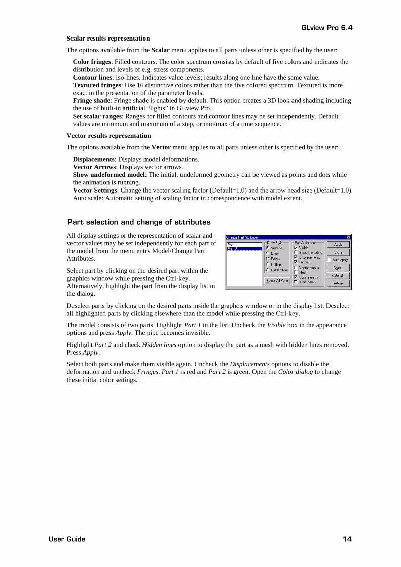
Part selection and change of attributes
All display settings or the representation of scalar and vector values may be set independently for each part of the model from the menu entry Model/Change Part Attributes.
Select part by clicking on the desired part within the graphics window while pressing the Ctrl-key. Alternatively, highlight the part from the display list in the dialog.
Deselect parts by clicking on the desired parts inside the graphcis window or in the display list. Deselect all highlighted parts by clicking elsewhere than the model while pressing the Ctrl-key.
The model consists of two parts. Highlight Part 1 in the list. Uncheck the Visible box in the appearance options and press Apply. The pipe becomes invisible.
Highlight Part 2 and check Hidden lines option to display the part as a mesh with hidden lines removed. Press Apply.
Select both parts and make them visible again. Uncheck the Displacements options to disable the deformation and uncheck Fringes. Part 1 is red and Part 2 is green. Open the Color dialog to change these initial color settings.
GLview Pro 6.4
User Guide 15
Tutorial 2: Advanced features
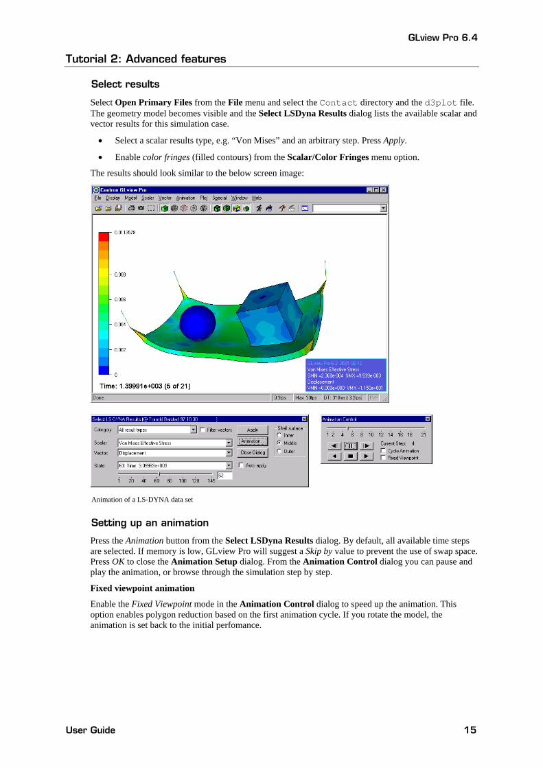
Select results
Select Open Primary Files from the File menu and select the Contact directory and the d3plot file. The geometry model becomes visible and the Select LSDyna Results dialog lists the available scalar and vector results for this simulation case.
• Select a scalar results type, e.g. “Von Mises” and an arbitrary step. Press Apply.
• Enable color fringes (filled contours) from the Scalar/Color Fringes menu option.
The results should look similar to the below screen image:
Animation of a LS-DYNA data set
Setting up an animation
Press the Animation button from the Select LSDyna Results dialog. By default, all available time steps are selected. If memory is low, GLview Pro will suggest a Skip by value to prevent the use of swap space. Press OK to close the Animation Setup dialog. From the Animation Control dialog you can pause and play the animation, or browse through the simulation step by step.
Fixed viewpoint animation
Enable the Fixed Viewpoint mode in the Animation Control dialog to speed up the animation. This option enables polygon reduction based on the first animation cycle. If you rotate the model, the animation is set back to the initial perfomance.
GLview Pro 6.4
User Guide 16
2D plotting
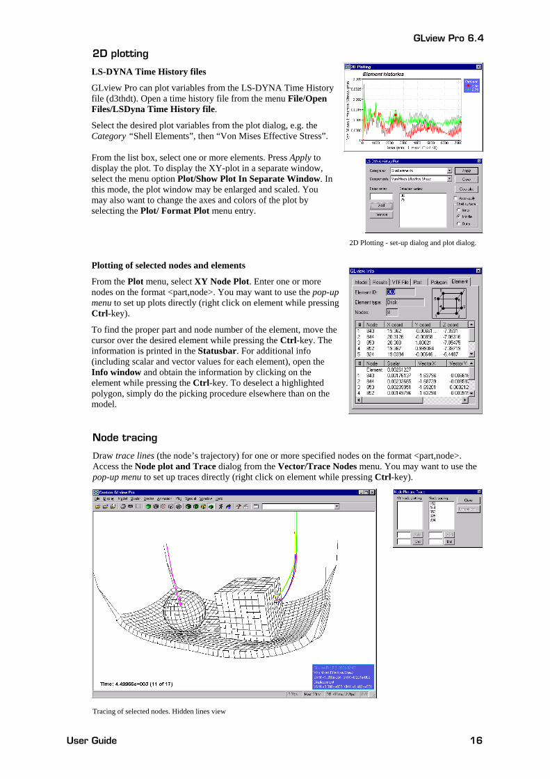
LS-DYNA Time History files
GLview Pro can plot variables from the LS-DYNA Time History file (d3thdt). Open a time history file from the menu File/Open Files/LSDyna Time History file.
Select the desired plot variables from the plot dialog, e.g. the Category “Shell Elements”, then “Von Mises Effective Stress”.
From the list box, select one or more elements. Press Apply to display the plot. To display the XY-plot in a separate window, select the menu option Plot/Show Plot In Separate Window. In this mode, the plot window may be enlarged and scaled. You may also want to change the axes and colors of the plot by selecting the Plot/ Format Plot menu entry.
2D Plotting - set-up dialog and plot dialog.
Plotting of selected nodes and elements
From the Plot menu, select XY Node Plot. Enter one or more nodes on the format <part,node>. You may want to use the pop-up menu to set up plots directly (right click on element while pressing Ctrl-key).
To find the proper part and node number of the element, move the cursor over the desired element while pressing the Ctrl-key. The information is printed in the Statusbar. For additional info (including scalar and vector values for each element), open the Info window and obtain the information by clicking on the element while pressing the Ctrl-key. To deselect a highlighted polygon, simply do the picking procedure elsewhere than on the model.
Node tracing
Draw trace lines (the node’s trajectory) for one or more specified nodes on the format <part,node>. Access the Node plot and Trace dialog from the Vector/Trace Nodes menu. You may want to use the pop-up menu to set up traces directly (right click on element while pressing Ctrl-key).
Tracing of selected nodes. Hidden lines view
GLview Pro 6.4
User Guide 17
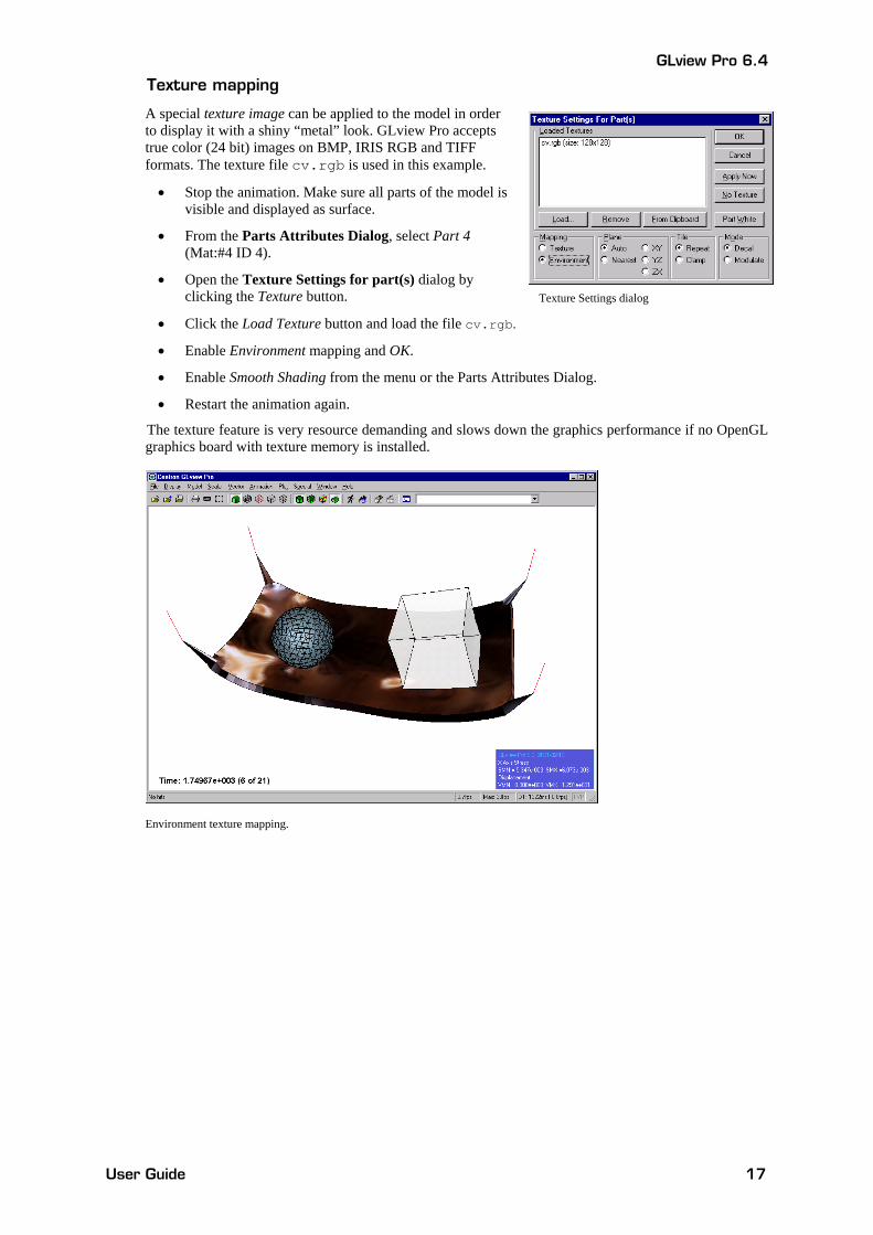
Texture mapping
A special texture image can be applied to the model in order to display it with a shiny “metal” look. GLview Pro accepts true color (24 bit) images on BMP, IRIS RGB and TIFF formats. The texture file cv.rgb is used in this example.
• Stop the animation. Make sure all parts of the model is visible and displayed as surface.
• From the Parts Attributes Dialog, select Part 4 (Mat:#4 ID 4).
• Open the Texture Settings for part(s) dialog by clicking the Texture button.
• Click the Load Texture button and load the file cv.rgb.
• Enable Environment mapping and OK.
• Enable Smooth Shading from the menu or the Parts Attributes Dialog.
• Restart the animation again.
The texture feature is very resource demanding and slows down the graphics performance if no OpenGL graphics board with texture memory is installed.
Environment texture mapping.
Texture Settings dialog
GLview Pro 6.4
User Guide 18
5 Tips and hints Menus and user interface
Command and Message window
The window displays all commands entered from the command prompt with messages and additional information. All menu and dialog actions are printed as commands.
• Tab completion of commands: Use the TAB-key to complete a command entered in the command prompt. If the entered text string is not unique, all matching commands are listed. When the command is unique, available parameters and a brief explanation of the command is printed.
• Help on sub commands: Type “?” after a command to see available sub commands (e.g. plt ?).
• Command help: Press F1 to get more help on a typed command.
Please note that some commands will not work until the required information or mode is present; e.g. iso-surface is not available when volume data is not loaded.
Info dialog Open the Info window from the Window menu to obtain more information about element type, node number, part number, scalar/vector values, etc. Click on selected elements while pressing the Ctrl-key to see the information in e.g. the “Element” sheet of the Info dialog.
• Selection of parts: To select an individual part, click while pressing the Shift-key. To select a set of parts, make the selection by clicking while pressing the Ctrl-key.
• Continuous picking: Select the menu option Special/Show Continuous Picking Info to obtain a continuous display of element info. While pressing the Ctrl-key, move the mouse cursor over the elements to get more information.
Status bar information Look for useful information in the status bar:
• Part/element/node information: Place the mouse cursor over a polygon/element and wait one second to see additional information.
• Command information: Available command parameters and a brief explanation is printed in the status bar when using the command prompt.
• File loading progress bar: When loading files and setting up e.g. an animation, the file loading progress may be observed and cancelled.
Right-click mouse menu Open the pop-up menu by pressing the Ctrl-key and clicking the right mouse button while the cursor is positioned on the selected part. Please remember to always select a polygon or part (by using left mouse button while pressing the Ctrl-key) before using the right-click feature! From this menu you can:
• Show information of the model.
• Hide/display the selected part(s).
• Set up node plots and node traces if time-dependent data is loaded.
• Change the model’s rotation point to other than the center of the total model (default).
Drag & drop files Any files associated or supported by GLview Pro can be opened directly by dragging the file inside the graphics window or GLview Pro icon. Please note that files must be opened in certain orders, e.g. a file containing the geometry description must be loaded before a view-file or certain command files.
Context sensitive menus The entries in the menus will change after a geometry file or a results database have been loaded. This feature is implemented in order to make the file access procedure more logic and user-friendly. To override this, change the “Auto” setting in the file open dialog to another choice.
GLview Pro 6.4
User Guide 19
Change part attributes Set draw styles (display settings) and other attributes for each part (e.g. Material IDs in LS-DYNA) from the Change Part Attributes dialog (Model menu).
Select part(s) directly from the dialog, alternatively, select a part by clicking on the desired part in the graphics window while pressing the Ctrl-key. The selected part(s) will be outlined by a bounding box.
• Color dialog: Set color for selected part(s)/materials
• Material dialog: Set material properties for selected parts/materials.
• Texture dialog: Load and assign texture images for selected parts/materials.
Using GLview Pro without hardware graphics
If graphics hardware supporting OpenGL 3D acceleration is not installed, the graphics performance of GLview Pro is solely dependent on the processor speed and the amount of installed RAM. The performance will be poor when visualizing large models and results.
However, there are ways to get around these limitations and—to some extent—increase the graphics speed (or at least make it easier to manipulate the models).
How to increase graphics performance
Outline: Move model as outline (Model/Move As/Outline) or bounding box.
Animation:
• Skip steps (e.g. load every tenth step) when loading large results databases. • Use the Fixed Viewpoint animation mode (select this option from the Animation Control dialog). • Load one analysis step at the time (one by one) from the Results dialog.
Hide parts: Hide selected parts of the model when examining large geometries.
The above listed features cannot be applied to all models, but it may be useful to be aware of them.
Settings that decrease graphics performance The below menu settings increases response time heavily when displaying large model files without OpenGL graphics hardware:
• Texture and environment mapping • Textured fringes (show scalars as textured fringes) • Vector arrows and polygon normals • Node numbers • Contour lines • Smoothed points (anti-aliased points) • Smooth shading (gouraud shading) • Smooth lines (anti-aliased lines) • Fringe shade
GLview Pro 6.4
User Guide 20
6 Commands Please refer to the GLview Pro on-line help for a complete reference.
Command line options
GLview Pro can be executed from a Unix/Linux shell, from a DOS prompt or via a Windows shortcut with several command line options.
Example: File open % glview d3plot
This assumes that the LS-DYNA statedatabase file d3plot is located in the GLview Pro directory. If other location, enter the full or relative path name.
Example: Set window size and position % glview -pos 100 100 640 480
Positions the window at position (100,100) and with 3D viewport size 640x480.
In Windows you may include these parameters in the Windows shortcut’s properties (Target field)).
Commands
GLview Pro has over 600 commands. In the online help these are grouped in the below categories.
Command groups:
File handling commands Display commands Model commands Material properties commands Polygon commands Object transformations commands Point and line commands Animation commands Complex results commands Text and drawing commands Scalar commands Viewing and clipping commands Vector commands Model information commands Volume commands Texture and environment mapping commands Boundary conditions commands Plotting and tracing commands Background commands Miscellaneous commands
GLview Pro 6.4
User Guide 21
7 FEA file readers Import filters for commercial codes
GLview Pro features direct file reading of:
• ABAQUS: Binary post file (.fil, .odb) (ODB support for Windows only) • ANSYS: Binary results files (.rst,. rth and .rfl) • LS-DYNA: State Database (d3plot), Time History File (d3thdt), ASCII plot files • I-DEAS: ASCII universal file (.unv) • MSC.Nastran: Binary Output 2 files (.op2) • MSC.Marc ASCII (.t19) & binary (.t16) • RADIOSS: Binary ModAnim file • NE/Nastran: Binary Output 2 files (.op2) and bulk data • FEMAP: ASCII neutral file (.neu)
Please refer to the GLview Pro on-line help for a complete reference on supported formats.
Import filters for GLview internal file formats
• MOVIE.BYU: ASCII and binary.
• Open VTF format: ASCII and binary. Only GLview Pro can read the open format, which can be written by GLview Express Writer or your own code. The format description available on Ceetron’s web-site.
• Encrypted VTF format: Binary. GLview Pro, GLview Express and 3D Plug-in can read the encrypted format. Encrypted files can be generated by GLview Pro, or a licensed version of GLview Express Writer.
GLview Pro 6.4
User Guide 22
Ceetron ASA P.O. Box 1247 Pirsenteret N-7462 Trondheim Norway
Tel: +47 73 54 61 50 Fax: +47 73 54 61 44
E-mail: [email protected] [email protected] [email protected]
www.ceetron.com