Embed Size (px)
Citation preview
8/19/2019 GM7 & GM7U -General Information
http://slidepdf.com/reader/full/gm7-gm7u-general-information 1/5
GLOFA-GM7Programmable Logic Controller
IGLOFA-GM Series 9
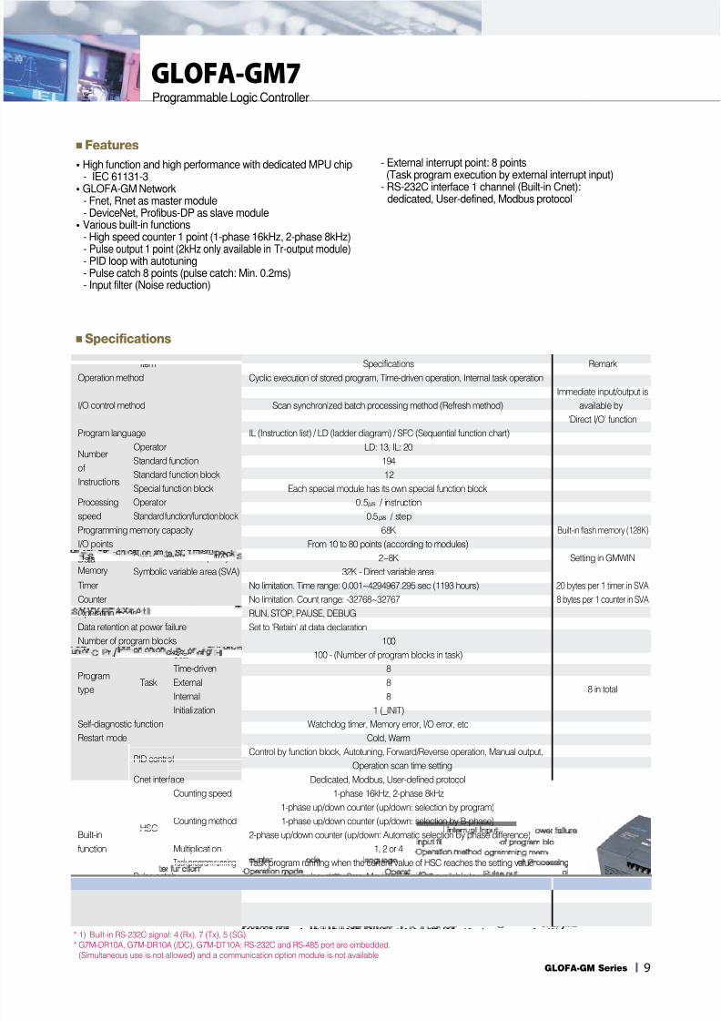
■Features
�High function and high performance with dedicated MPU chip
- IEC 61131-3�GLOFA-GM Network
- Fnet, Rnet as master module- DeviceNet, Profibus-DP as slave module�Various built-in functions
- High speed counter 1 point (1-phase 16kHz, 2-phase 8kHz)- Pulse output 1 point (2kHz only available in Tr-output module)- PID loop with autotuning- Pulse catch 8 points (pulse catch: Min. 0.2ms)- Input filter (Noise reduction)
- External interrupt point: 8 points
(Task program execution by external interrupt input)- RS-232C interface 1 channel (Built-in Cnet):dedicated, User-defined, Modbus protocol
■Specifications
* 1) Built-in RS-232C signal: 4 (Rx), 7 (Tx), 5 (SG)
* G7M-DR10A, G7M-DR10A (/DC), G7M-DT10A: RS-232C and RS-485 port are embedded.
(Simultaneous use is not allowed) and a communication option module is not available.
Item Specifications Remark
Operation method Cyclic execution of stored program, Time-driven operation, Internal task operation
Immediate input/output is
I/O control method Scan synchronized batch processing method (Refresh method) available by
‘Direct I/O’ function
Program language IL (Instruction list) / LD (ladder diagram) / SFC (Sequential function chart)
NumberOperator LD: 13, IL: 20
ofStandard function 194
InstructionsStandard function block 12
Special function block Each special module has its own special function block
Processing Operator 0.5㎲ / instruction
speed Standard function / function block 0.5㎲ / step
Programming memory capacity 68K Built-in flash memory (128K)
I/O points From 10 to 80 points (according to modules)
Data Direct variable area (DVA) 2~8K Setting in GMWIN
Memory Symbolic variable area (SVA) 32K - Direct variable area
Timer No limitation. Time range: 0.001~4294967.295 sec (1193 hours) 20 bytes per 1 timer in SVA
Counter No limitation. Count range: -32768~32767 8 bytes per 1 counter in SVA
Operation mode RUN, STOP, PAUSE, DEBUG
Data retention at power failure Set to 'Retain' at data declaration
Number of program blocks 100
Scan 100 - (Number of program blocks in task)
ProgramTime-driven 8
typeTask External 8
Internal 88 in total
Initialization 1 (_INIT)
Self-diagnostic function Watchdog timer, Memory error, I/O error, etc
Restart mode Cold, Warm
PID controlControl by function block, Autotuning, Forward/Reverse operation, Manual output,
Operation scan time setting
Cnet interface Dedicated, Modbus, User-defined protocol
Counting speed 1-phase 16kHz, 2-phase 8kHz
1-phase up/down counter (up/down: selection by program)
HSCCounting method 1-phase up/down counter (up/down: selection by B-phase)
Built-in 2-phase up/down counter (up/down: Automatic selection by phase difference)
function Multiplication 1, 2 or 4
Task program running Task program running when the current value of HSC reaches the setting value
Pulse catch Min. pulse width: 2ms, Maximum 8 points available to use
Pulse output2kHz, 1Ch
External interrupt Input 8 points
Input filter function 0~15ms (Setting by 1ms)
8/19/2019 GM7 & GM7U -General Information
http://slidepdf.com/reader/full/gm7-gm7u-general-information 2/5
I10
GLOFA-GM7Programmable Logic Controller
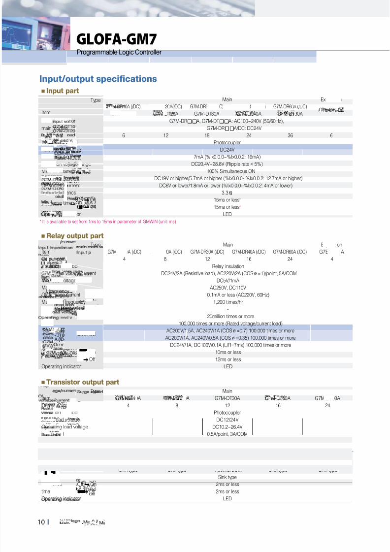
Input/output specifications
■Input part
Type Main Expansion
G7M-DR10A (/DC) G7M-DR20A(/ DC) G7M-DR30A (/DC) G7M-DR40A (/DC) G7M-DR60A (/DC)G7E-DR10A
Item G7M-DT10A G7M-DT20A G7M-DT30A G7M-DT40A G7M-DT60A
Power supply for G7M-DRA, G7M-DTA: AC100~240V (50/60Hz),
main module G7M-DRA/DC: DC24V
Input point 6 12 18 24 36 6
Insulation method Photocoupler
Rated input voltage DC24V
Rated input current 7mA (%Ix0.0.0~%Ix0.0.2: 16mA)
Operation voltage range DC20.4V~28.8V (Ripple rate < 5%)
Max. simultaneous input 100% Simultaneous ON
On voltage/current DC19V or higher/5.7mA or higher (%Ix0.0.0~%Ix0.0.2: 12.7mA or higher)
Off voltage /current DC6V or lower/1.8mA or lower (%Ix0.0.0~%Ix0.0.2: 4mA or lower)
Input impedance 3.3㏀
Response timeOffOn 15ms or less*
OnOff 15ms or less*
Operating indicator LED
* It is available to set from 1ms to 15ms in parameter of GMWIN (unit: ms)
■Relay output part
Type Main Expansion
Item G7M-DR10A (/ DC) G7M-DR20A (/ DC) G7M-DR30A (/ DC) G7M-DR40A (/DC) G7M-DR60A (/ DC) G7E-DR10A
Output point 4 8 12 16 24 4
Insulation method Relay insulation
Rated load voltage/current DC24V/2A (Resistive load), AC220V/2A (COS∅=1)/point, 5A/COM
Min. load voltage /current DC5V/1mA
Max. load voltage AC250V, DC110VOff leakage current 0.1mA or less (AC220V, 60Hz)
Max. on/off frequency 1,200 times/hr
Surge absorber -
Mechanical 20million times or more
100,000 times or more (Rated voltage/current load)
Service lifeElectrical
AC200V/1.5A, AC240V/1A (COS∅=0.7) 100,000 times or more
AC200V/1A, AC240V/0.5A (COS∅=0.35) 100,000 times or more
DC24V/1A, DC100V/0.1A (L/R=7ms) 100,000 times or more
Response timeOffOn 10ms or less
OnOff 12ms or less
Operating indicator LED
■Transistor output part
Type Main
Item G7M-DT10A G7M-DT20A G7M-DT30A G7M-DT40A G7M-DT60A
Output point 4 8 12 16 24
Insulation method Photocoupler
Rated load voltage DC12/24V
Operating load voltage DC10.2~26.4V
Rated load current 0.5A/point, 3A/COM
Off leakage current 0.1mA or less
On voltage drop 1.5V or less (Max.load)
Surge absorber Clamp diode
4 points/COM 8 points/COM 8 points/COM 8 points/COM (×2) 8 points/COM (×3)
Common Sink type Sink type 4 points/COM Sink type Sink type
Sink type
Response OffOn 2ms or lesstime OnOff 2ms or less
Operating indicator LED
8/19/2019 GM7 & GM7U -General Information
http://slidepdf.com/reader/full/gm7-gm7u-general-information 3/5
11IGLOFA-GM Series
■Specifications
Item Specifications Remark20 30 40 60
DR type: Relay output
Output typeDRT type: NPN Tr output + Relay outputDT (N) type: NPN Tr outputDT (P) type: PNP Tr output
Operation method Cyclic execution of stored program, Time-driven operation, Internal task operationI/O control method Scan synchronized batch processing method (Refresh method)Program language IL (Instruction list) / LD (ladder diagram) / SFC (Sequential function chart)
NumberOperator LD: 13, IL: 20
ofStandard function 194
InstructionsStandard function block 12Special function block Function blocks for built-in functions, special, communication modules
Processing speed for operator 0.1~0.9㎲ /stepProgram memory capacity 132 Kbyte (including parameters)I/O points Input: 12, Output: 8 Input: 18, Output: 12 Input: 24, Output: 16 Input: 36, Output: 24 Max. 120
Data Direct variable area (DVA) 14KMemory Symbolic variable area (SVA) 30KTimer No limitation. Time range: 0.001~4294967.295 sec (1193 hours)Counter No limitation. Count range: -32768~32767Operation mode RUN, STOP, PAUSE, DEBUGData retention at power failure Set to 'Retain' at data declarationNumber of program blocks 100
Scan 100 - (Number of program blocks in task)Time-driven 8
Program External 8type Task Internal 8 8 in total
HSC 4Initialization 1 (_INIT)
Self-diagnostic function Watchdog timer, Memory error, I/O error, etcRestart mode Cold, Warm
PID controlControl by function block, Autotuning, Forward/Reverse operation, Manual output,
Delta MV, SV ramp function, Anti-windup, etcCnet interface Dedicated, LG Inverter, MODBUS, User-defined, No protocol
Counting speed1-phase: 100kHz (2channels) / 20kHz (2channels)2-phase: 50kHz (1channel) / 10kHz (1channel)1-phase up counter
HSCCounting method
1-phase up/down counter (up/down: selection by B-phase)2-phase up/down counter (up/down: pulse input)2-phase up/down counter (up/down: automatic selection by phase difference)
Built-inAdditional Internal/external preset, Latch counter, Comparison output, RPM
function BasicNo. of control axis: 2, Control method: PTP/speed/synchronous, Control unit: pulsePositioning data: 20/axis (operation step no. 1~20)Position method: absolute/incremental, Operation method: single/repeat
Position PositioningAddress range: -2,147,483,648~2,147,483,647 DRT/DTSpeed: Max. 100kpps (setting range: 5~100,000pps) type onlyAcceleration/Deceleration method: Trapezoidal method
Return to origin DOG/HOME (ON), DOG/HOME (OFF), approximate originJOG Setting range: 5~100,000 (high/low speed)
Pulse catch Minimum pulse width: 10㎲ (2 points), 50㎲ (2 points)External interrupt 10㎲ (2 points), 50㎲ (2 points)Input filter 0, 1, 2, 5, 10, 20, 50, 100, 200, 500, 1000ms (Default: 10ms)
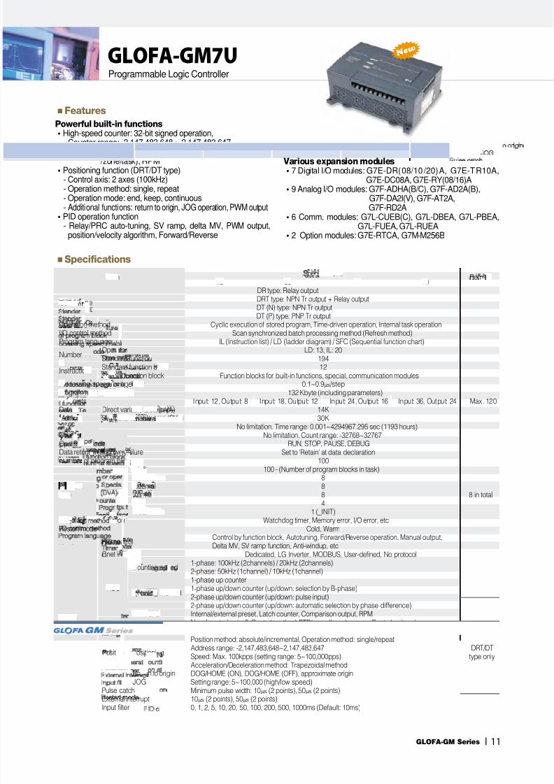
GLOFA-GM7UProgrammable Logic Controller
■Features
Powerful built-in functions
�High-speed counter: 32-bit signed operation,- Counter range: -2,147,483,648 ~ 2,147,483,647- Function: ring counter, latch counter, comparison (equal
/zone/task), RPM�Positioning function (DRT/DT type)
- Control axis: 2 axes (100kHz)- Operation method: single, repeat- Operation mode: end, keep, continuous- Additional functions: return to origin, JOG operation, PWM output
�PID operation function- Relay/PRC auto-tuning, SV ramp, delta MV, PWM output,position/velocity algorithm, Forward/Reverse
Various expansion modules�7 Digital I/O modules: G7E-DR(08/10/20)A, G7E-TR10A,
G7E-DC08A, G7E-RY(08/16)A�9 Analog I/O modules: G7F-ADHA(B/C), G7F-AD2A(B),
G7F-DA2I(V), G7F-AT2A,G7F-RD2A
�6 Comm. modules: G7L-CUEB(C), G7L-DBEA, G7L-PBEA,G7L-FUEA, G7L-RUEA
�2 Option modules: G7E-RTCA, G7M-M256B
8/19/2019 GM7 & GM7U -General Information
http://slidepdf.com/reader/full/gm7-gm7u-general-information 4/5
12 I
GLOFA-GM7UProgrammable Logic Controller
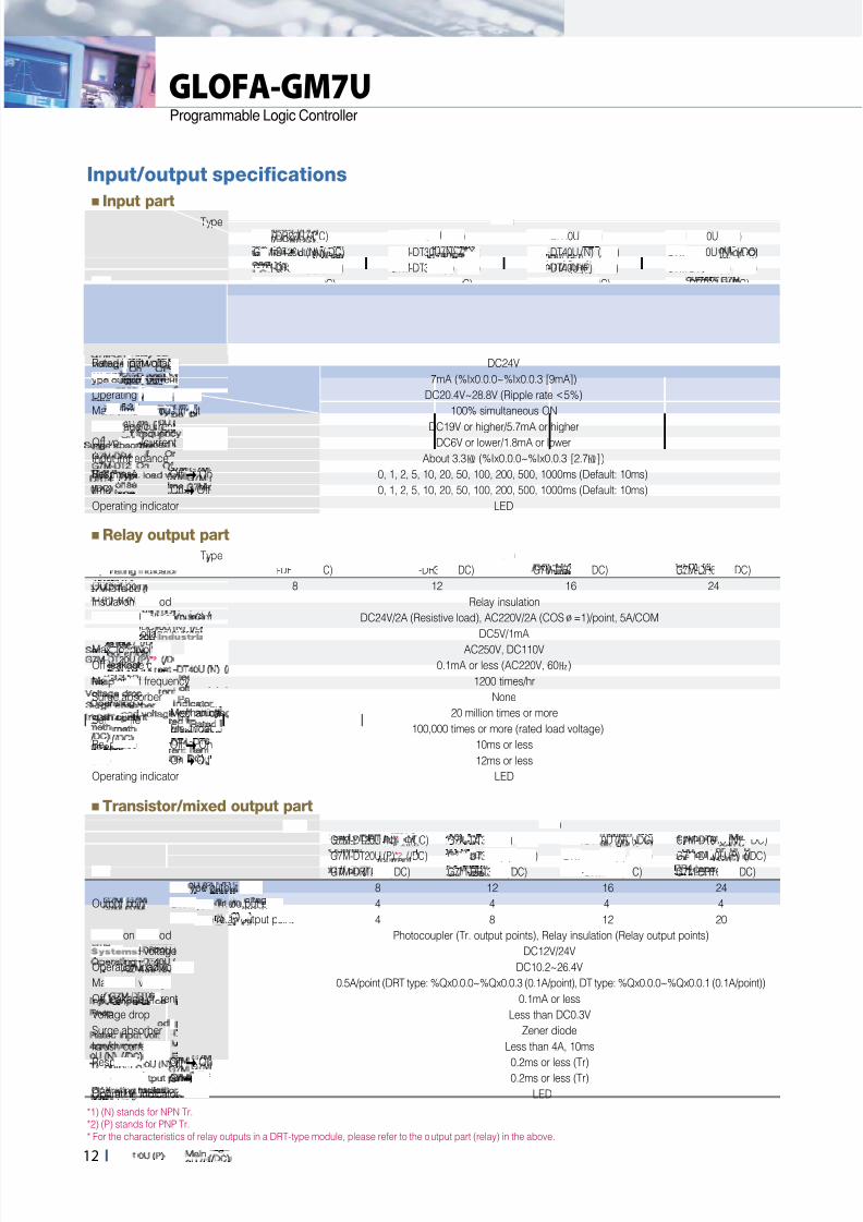
Input/output specifications
■Input part
Type Main
G7M-DR20U (/DC) G7M-DR30U (/DC) G7M-DR40U (/DC) G7M-DR60U (/DC)
G7M-DT20U (N) (/DC) G7M-DT30U (N) (/DC) G7M-DT40U (N) (/DC) G7M-DT60U (N) (/DC)
G7M-DT20U (P) ( /DC) G7M-DT30U (P) (/DC) G7M-DT40U (P) (/DC) G7M-DT60U (P) (/DC)
Item G7M-DRT20U (/DC) G7M-DRT30U (/DC) G7M-DRT40U (/DC) G7M-DRT60U (/DC)
Power supplyG7M-DRU, G7M-DTU, G7M-DRTU: AC100~240V (50/60Hz),
G7M-DRU/DC, G7M-DTU/DC, G7M-DRTU/DC: DC12/24V
Input point 12 18 24 36
Insulation method Photocoupler
Rated input voltage DC24V
Rated input current 7mA (%Ix0.0.0~%Ix0.0.3 [9mA])
Operating voltage range DC20.4V~28.8V (Ripple rate <5%)
Max. simultaneous input 100% simultaneous ON
On voltage/current DC19V or higher/5.7mA or higherOff voltage /current DC6V or lower/1.8mA or lower
Input impedance About 3.3㏀ (%Ix0.0.0~%Ix0.0.3 [2.7㏀])
Response OffOn 0, 1, 2, 5, 10, 20, 50, 100, 200, 500, 1000ms (Default: 10ms)
time OnOff 0, 1, 2, 5, 10, 20, 50, 100, 200, 500, 1000ms (Default: 10ms)
Operating indicator LED
■Relay output part
Type Main
Item G7M-DR20U (/DC) G7M-DR30U (/ DC) G7M-DR40U (/ DC) G7M-DR60U (/ DC)
Output point 8 12 16 24
Insulation method Relay insulation
Rated load voltage /current DC24V/2A (Resistive load), AC220V/2A (COS∅=1)/point, 5A/COM
Min. load voltage/current DC5V/1mA
Max. load voltage AC250V, DC110V
Off leakage current 0.1mA or less (AC220V, 60㎐)
Max. on/off frequency 1200 times/hr
Surge absorber None
Service lifeMechanical 20 million times or more
Electrical 100,000 times or more (rated load voltage)
Response OffOn 10ms or less
time OnOff 12ms or less
Operating indicator LED
■Transistor/mixed output part
*1) (N) stands for NPN Tr.*2) (P) stands for PNP Tr.
* For the characteristics of relay outputs in a DRT-type module, please refer to the output part (relay) in the above.
Type Main
G7M-DT20U (N)*1 (/DC) G7M-DT30U (N) (/DC) G7M-DT40U (N) (/DC) G7M-DT60U (N) (/ DC)
G7M-DT20U (P)*2 (/DC) G7M-DT30U (P) ( /DC) G7M-DT40U (P) (/DC) G7M-DT60U (P) (/ DC)Item G7M-DRT20U (/ DC) G7M-DRT30U (/ DC) G7M-DRT40U (/DC) G7M-DRT60U (/ DC)
DT-type output point 8 12 16 24
Output point DRT-type Tr. output point 4 4 4 4
DRT-type relay output point 4 8 12 20
Insulation method Photocoupler (Tr. output points), Relay insulation (Relay output points)
Rated load voltage DC12V/24V
Operation load voltage DC10.2~26.4V
Max. load voltage 0.5A/point (DRT type: %Qx0.0.0~%Qx0.0.3 (0.1A/point), DT type: %Qx0.0.0~%Qx0.0.1 (0.1A/point))
Off leakage current 0.1mA or less
Voltage drop Less than DC0.3V
Surge absorber Zener diode
Inrush current Less than 4A, 10ms
Response OffOn 0.2ms or less (Tr)
time OnOff 0.2ms or less (Tr)
Operating indicator LED

8/19/2019 GM7 & GM7U -General Information
http://slidepdf.com/reader/full/gm7-gm7u-general-information 5/5
13IGLOFA-GM Series
Expansion specifications
■Input part
Type Expansion
Item G7E-DC08A G7E-DR08A G7E-DR10A G7E-DR20A
Input point 8 4 6 12
Insulation method Photocoupler
Rated input voltage DC24V
Rated input current 7mA
Operating voltage range DC20.4V~28.8V (Ripple rate5%)
Max. simultaneous input 100% simultaneous ON
On voltage /current DC19V or higher/5.7mA or higher
Off voltage /current DC6V or lower/1.8mA or lower
Input impedance About 3.3㏀
Response OffOn 0, 1, 2, 5, 10, 20, 50, 100, 200, 500, 1000ms (Default: 10ms)
time OnOff 0, 1, 2, 5, 10, 20, 50, 100, 200, 500, 1000ms (Default: 10ms)Operating indicator LED
* Slim type
■Relay output part
Type Expansion
Item G7E-RY08A* G7E-RY16A G7E-DR08A * G7E-DR10A G7E-DR20A
Output point 8 16 4 4 8
Insulation method Relay insulation
Rated load voltage /current DC24V/2A (Resistive load), AC220V/2A (COS∅=1)/point, 5A/COM
Min. load voltage /current DC5V/1mA
Max. load voltage AC250V, DC110VOff leakage current 0.1mA or less (AC220V, 60㎐)
Max. on/off frequency 1200 times/hr
Surge absorber None
Service lifeMechanical 20 million times or more
Electrical 100,000 times or more (rated load voltage)
Response OffOn 10ms or less
time OnOff 12ms or less
Operating indicator LED
* *
■Transistor output
Type Expansion
Item G7E-TR10A
Output point 10
Insulation method Photocoupler
Rated load voltage DC12/24V
Operation load voltage DC10.2~26.4V
Max. load voltage 0.5A/points, 4A/COM
Off leakage current 0.1mA or less
Inrush current Less than 4A, 10ms
Voltage drop Less than DC1.5V
Surge absorber Clamp diode
Response OffOn 2ms or lower
time OnOff 2ms or lower
Operating indicator LED


![The Geordie - Bytown Ukulele Books/Wukulele... · [Gm7]That ain't workin' that's the way you do it Get your money for nothin' [F]and chicks for [Gm7] free [Gm7]Now](https://img.pdfslide.net/doc/110x75/5aa9df607f8b9a77188d6ae8/the-geordie-bytown-bookswukulelegm7that-aint-workin-thats-the-way-you.jpg)