Embed Size (px)
Citation preview
1
1
GMPLS networks and optical network testbedsMalathi Veeraraghavan
ProfessorCharles L. Brown Dept. of Electrical & Computer Engineering
University of [email protected]
Tutorial at ICACT09Feb. 2009
GMPLS: Generalized MultiProtocol Label Switched networks(MPLS, SONET, WDM, SDM, VLAN)
2
Outline
• Principles– Different types of connection-oriented networks
• Technologies– Single network– Internetworking
• Usage– Commercial networks– Research & Education Networks (REN)
2
3
Principles
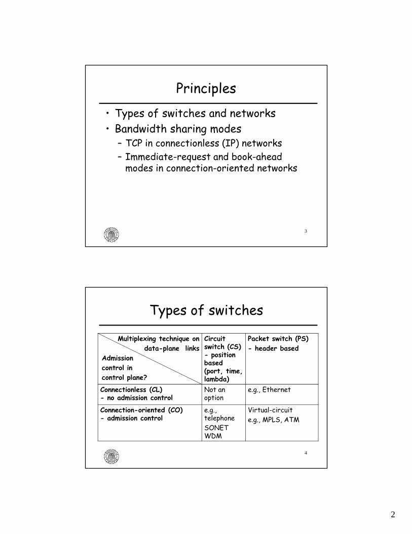
• Types of switches and networks• Bandwidth sharing modes– TCP in connectionless (IP) networks– Immediate-request and book-ahead modes in connection-oriented networks
4
Types of switches
Multiplexing technique on
data-plane links
Admission
control in
control plane?
Circuit switch (CS)- position based (port, time, lambda)
Packet switch (PS)
- header based
Connectionless (CL) - no admission control
Not an option
e.g., Ethernet
Connection-oriented (CO)- admission control
e.g., telephoneSONET WDM
Virtual-circuit e.g., MPLS, ATM
3
5
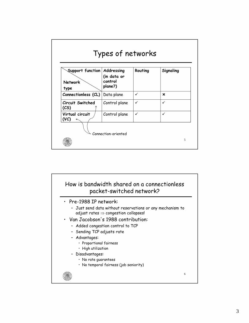
Types of networks
Support function
Network
type
Addressing
(in data or control plane?)
Routing Signaling
Connectionless (CL) Data plane � �
Circuit Switched (CS)
Control plane � �
Virtual circuit (VC)
Control plane � �
Connection-oriented
6
How is bandwidth shared on a connectionless packet-switched network?
• Pre-1988 IP network:– Just send data without reservations or any mechanism to adjust rates ⇒ congestion collapses!
• Van Jacobson's 1988 contribution:– Added congestion control to TCP– Sending TCP adjusts rate– Advantages:
• Proportional fairness• High utilization
– Disadvantages:• No rate guarantees• No temporal fairness (job seniority)

4
7
TCP throughput
• B: Throughput in congestion-avoidance phase• RTT: Round-trip time• b: an ACK is sent every b segments (b is typically 2)• p: packet loss rate on path• T0: initial retransmission time out in a sequence of retries • Effective rate = min (r,B)• r: bottleneck link rate• Padhye, Firoui, Towsley, Kurose, ACM Sigcomm 98 paper
)321()8
33,1min(
32
1
20 pp
bpT
bpRTT
B++
=
8
TCP throughput
438750msCase 18
441.75msCase 17
12.430.1ms1GbpsCase 16
441750msCase 15
471.75msCase 14
92.410.1ms100Mbps
0.01Case 13
128750msCase 12
129.45msCase 11
8.640.1ms1GbpsCase 10
129350msCase 9
135.45msCase 8
82.930.1ms100Mbps
0.001Case 7
395.750msCase 6
39.65msCase 5
8.250.1ms1GbpsCase 4
396.550msCase 3
89.455msCase 2
82.250.1ms100 Mb/s0.0001Case 1
Round-trip delayBottleneck link ratePacket loss rate
Mean transfer delayfor a 1GB file (s)
Input parametersCase
~21Mbps
~2Mbps
5
9
Bandwidth sharing in circuit networks(immediate-request mode)
• Key difference:– Admission control– Intrinsic to circuit networks: position based mux
• Send a call setup request:– if requested bandwidth is available, it is allocated to the call
– if not, the call is blocked (rejected)• M/G/m/m model:
– m: number of circuits
10
ErlangB formula
m
Pu
k
mP
bb
m
k
k
m
b
ρ
ρ
ρ
×−=
∑
=
=
)1(
!/
!/
0
ρ: offered traffic load in Erlangsλ: call arrival rate
1/µ: mean call holding timem: number of circuitsPb: call blocking probabilityub: utilization
For a 1% call blocking probability, i.e., Pb = 0.01
ρ m ua
24.8%58.2%84.6%
110100
417117
µ
λρ =
If m is small, high utilization can only beachieved along with high call blocking probability

6
11
Bandwidth sharing mechanismsin CO networks
Bandwidth sharing mechanisms
Immediate-requestBook-ahead
BA-n/BA-First VBDS (Varying-Bandwidth Delayed Start)
unspecified call durationcall duration specified
session-type requests
data-type requestsBA-n BA-First
Users specify a set of call-initiation time options
Users are given first available timeslot
X. Zhu, Ph.D. Thesis, UVA, http://www.ece.virginia.edu/mv/html-files/students.html
Needed if per-callcircuit rate is a largefraction of link capacity(e.g., 1Gbps circuits on a 10Gbps link, m = 10)
12
• Example – To achieve a 90% utilizationwith a call blocking probability less than 10%• BA-First schemes are needed
when m < 59
– To achieve a 90% utilization with a call blocking probabilityless than 20%• BA-First schemes are needed
when m < 32
Comparison of Immediate-Request (IR) and Book-Ahead (BA) schemes
U: utilizationK: number of time periods in advance-reservation window
m=10, U = 80%: PB = 23.6% m=100, U = 80%: PB = 0.4%
IR m=10, K=10, U = 80%: PB = 0.4%BA
7
13
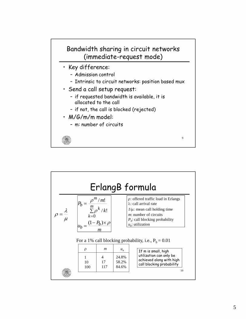
Virtual circuit (VC) networks
Call Admission Control
Scheduling(example: weighted fair queueing)
Traffic shaping/policing(example: leaky-bucket algorithm) Two additional
dimensionsin VC networks
Needed in circuit networks
Bandwidth sharing more complex, but better utilization PLUS service guarantees
14
Outline
• Principles– Different types of connection-oriented networks
�Technologies– Single network– Internetworking
• Usage– Commercial networks– Research & Education Networks (REN)
8
15
Technologies• GMPLS networks
� Data-(user-) plane protocols • packet-switched: MPLS, VLAN Ethernet• circuit-switched: SONET/SDH, WDM, SDM (space div. mux)
– Control-plane protocols: • RSVP-TE: signaling protocol• OSPF-TE: routing protocol• LMP: link management protocol
• Internetworking– GFP, VCAT, LCAS for SONET/SDH– PWE3 for MPLS networks– Digital wrapper for OTN
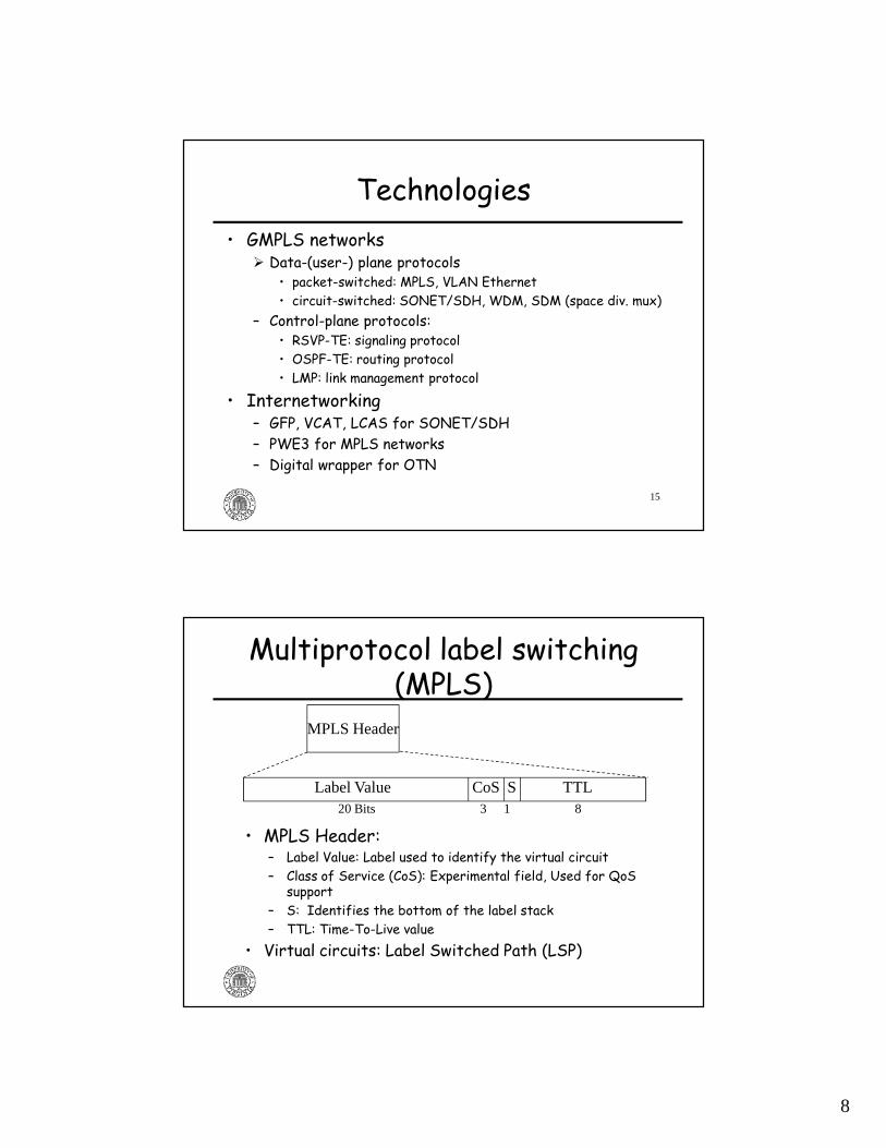
Multiprotocol label switching (MPLS)
• MPLS Header:– Label Value: Label used to identify the virtual circuit– Class of Service (CoS): Experimental field, Used for QoS
support– S: Identifies the bottom of the label stack– TTL: Time-To-Live value
• Virtual circuits: Label Switched Path (LSP)
MPLS Header
Label Value CoS S TTL20 Bits 3 1 8
9
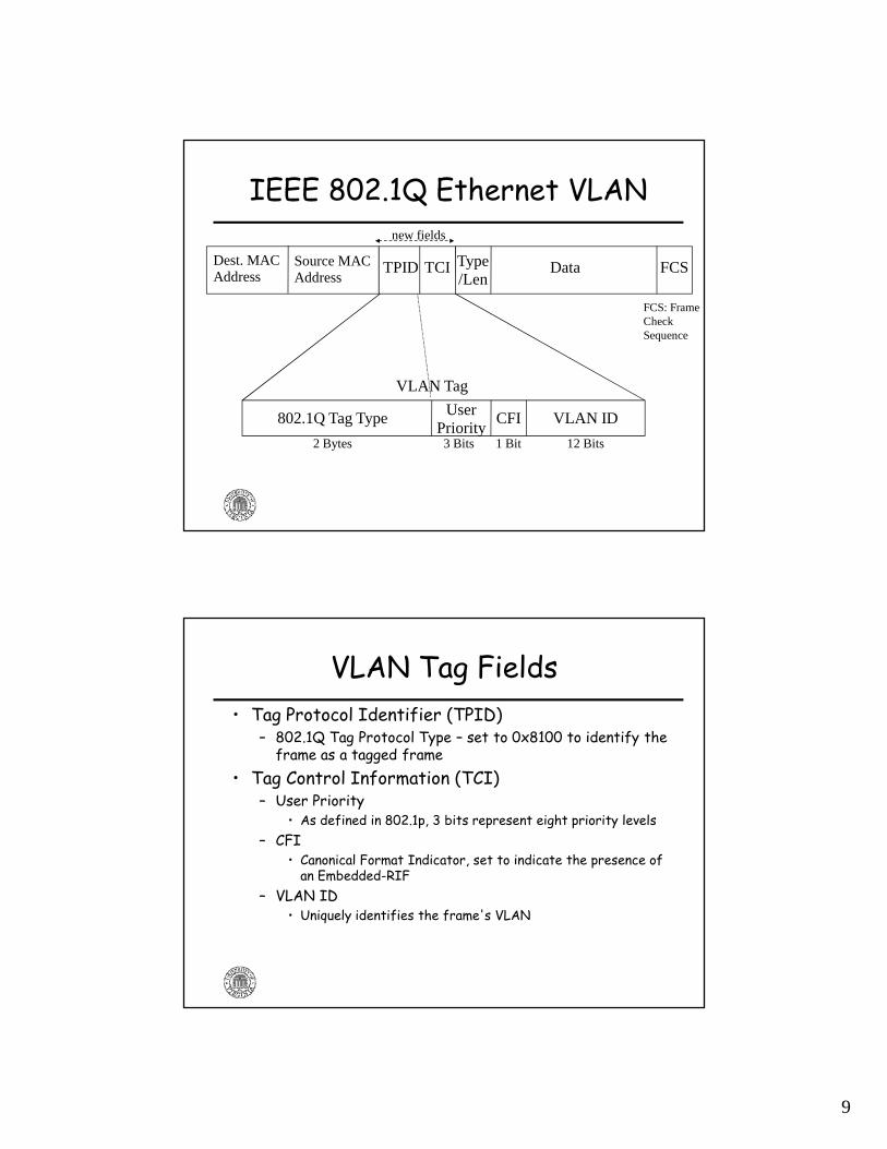
IEEE 802.1Q Ethernet VLAN
Dest. MAC Address
TPID TCI Type/Len
Data FCS
VLAN Tag
2 Bytes
802.1Q Tag Type CFIUser Priority
VLAN ID
3 Bits 1 Bit 12 Bits
Source MAC Address
FCS: FrameCheckSequence
new fields
VLAN Tag Fields• Tag Protocol Identifier (TPID)
– 802.1Q Tag Protocol Type – set to 0x8100 to identify the frame as a tagged frame
• Tag Control Information (TCI)– User Priority
• As defined in 802.1p, 3 bits represent eight priority levels– CFI
• Canonical Format Indicator, set to indicate the presence of an Embedded-RIF
– VLAN ID• Uniquely identifies the frame's VLAN
10
19
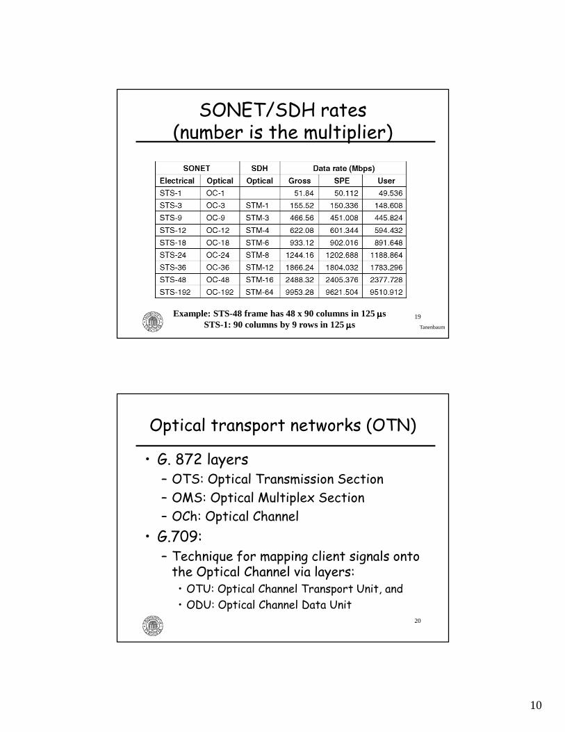
SONET/SDH rates(number is the multiplier)
Tanenbaum
Example: STS-48 frame has 48 x 90 columns in 125 µµµµsSTS-1: 90 columns by 9 rows in 125 µµµµs
20
Optical transport networks (OTN)
• G. 872 layers– OTS: Optical Transmission Section– OMS: Optical Multiplex Section– OCh: Optical Channel
• G.709:– Technique for mapping client signals onto the Optical Channel via layers:• OTU: Optical Channel Transport Unit, and• ODU: Optical Channel Data Unit
11
21
Layers within an OTN
Courtesy: T. Walker's tutorial
22
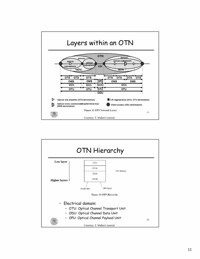
OTN Hierarchy
• Electrical domain:– OTU: Optical Channel Transport Unit– ODU: Optical Channel Data Unit– OPU: Optical Channel Payload Unit
Courtesy: T. Walker's tutorial
Low layer
Higher layers

12
23
G. 709 Optical Channel frame structure (digital wrapper)
• Optical channel (OCh) overhead: support operations, administration, and maintenance functions
• OCh payload: can be STM-N, ATM, IP, Ethernet, GFP frames, OTN ODUk, etc.
• FEC: Reed-Solomon RS(255, 239) code recommended; roughly introduces a 6.7% overhead
• Frame size: 4 rows of 4080 bytes• Frame period:
– OTU1 – 48.971 µs (payload data rate: roughly 2.488 Gbps )– OTU2 – 12.191 µs (payload data rate: roughly 9.995 Gbps )– OTU3 – 3.035 µs (payload data rate: roughly 40.15 Gbps )
OCh overhead OCh payload FEC
24
Technologies• GMPLS networks
– Data-(user-) plane protocols • packet-switched: MPLS, VLAN Ethernet, Intserv IP• circuit-switched: SONET/SDH, WDM, SDM
– Control-plane protocols: � RSVP-TE: signaling protocol• OSPF-TE: routing protocol• LMP: link management protocol
• Internetworking– GFP, VCAT, LCAS for SONET/SDH– PWE3 for MPLS networks– Digital wrapper for OTN
13
25
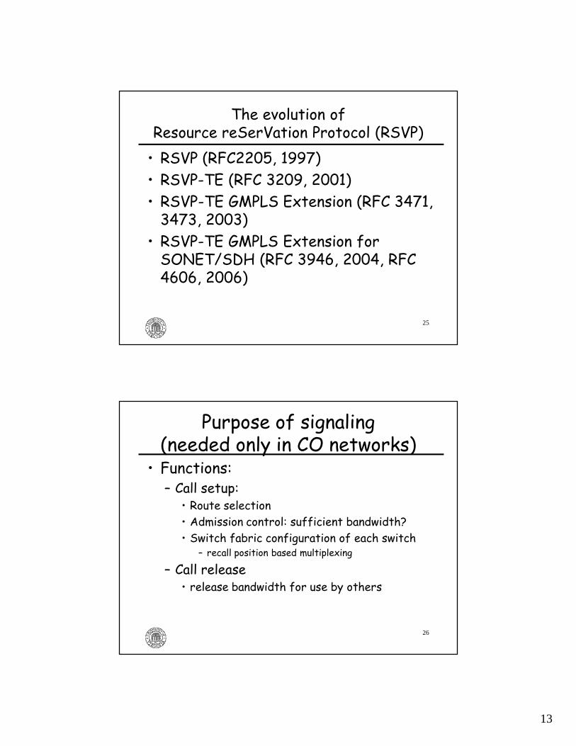
The evolution ofResource reSerVation Protocol (RSVP)• RSVP (RFC2205, 1997)• RSVP-TE (RFC 3209, 2001)• RSVP-TE GMPLS Extension (RFC 3471, 3473, 2003)
• RSVP-TE GMPLS Extension for SONET/SDH (RFC 3946, 2004, RFC 4606, 2006)
26
Purpose of signaling(needed only in CO networks)
• Functions:– Call setup:
• Route selection• Admission control: sufficient bandwidth?• Switch fabric configuration of each switch
– recall position based multiplexing
– Call release• release bandwidth for use by others
14
27
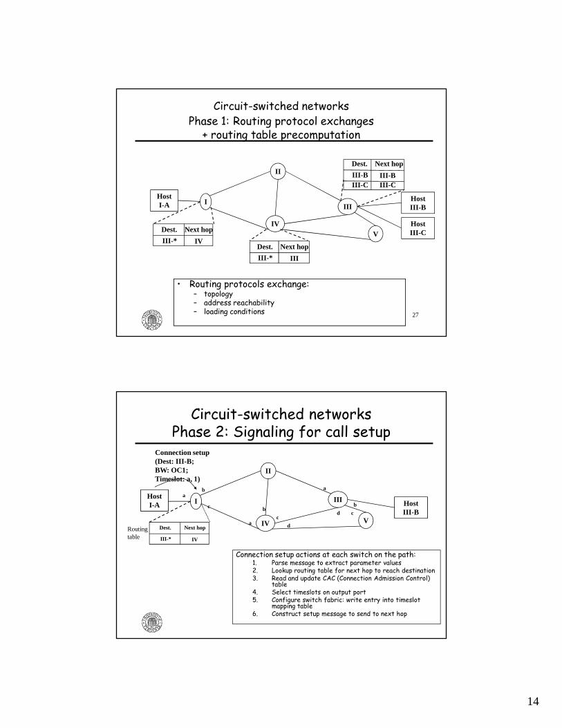
Circuit-switched networksPhase 1: Routing protocol exchanges + routing table precomputation
IV
I
V
III
II
Dest. Next hop
III-* IVDest. Next hop
III-* III
Dest. Next hop
III-B III-BIII-C III-C
Host I-A
Host III-B
Host III-C
• Routing protocols exchange:– topology– address reachability– loading conditions
28
Circuit-switched networksPhase 2: Signaling for call setup
Host I-A Host
III-B
I
IV V
III
II
ab
c
a
b
c
d
d c
a
b
Connection setup (Dest: III-B; BW: OC1; Timeslot: a, 1)
Dest. Next hop
III-* IV
Routingtable
Connection setup actions at each switch on the path:1. Parse message to extract parameter values2. Lookup routing table for next hop to reach destination3. Read and update CAC (Connection Admission Control)
table4. Select timeslots on output port5. Configure switch fabric: write entry into timeslot
mapping table6. Construct setup message to send to next hop
15
29
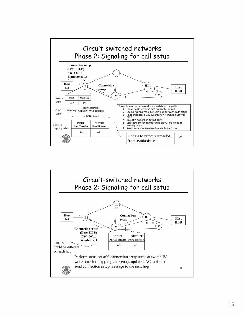
Circuit-switched networksPhase 2: Signaling for call setup
Connection setup actions at each switch on the path:1. Parse message to extract parameter values2. Lookup routing table for next hop to reach destination3. Read and update CAC (Connection Admission Control)
table4. Select timeslots on output port5. Configure switch fabric: write entry into timeslot
mapping table6. Construct setup message to send to next hop
Host I-A Host
III-B
I
IV V
III
II
a
b
c
a
b
c
d
d c
a
b
Dest. Next hop
III-* IV
Routingtable
Next hopInterface (Port);
Capacity; Avail timeslots
IV c; OC12; 1, 4, 5
CACtable
Connection setup (Dest: III-B; BW: OC1; Timeslot: a, 1)
INPUTPort /Timeslot
OUTPUTPort/Timeslot
a/1 c/1
Timeslotmapping table
Connection setup
Update to remove timeslot 1from available list
30
Circuit-switched networksPhase 2: Signaling for call setup
Host I-A Host
III-B
I
IV V
III
II
Connection setup
a
b
c
a
b
c
d
d c
a
b
INPUTPort /Timeslot
OUTPUTPort/Timeslot
a/1 c/2
Perform same set of 6 connection setup steps at switch IV write timeslot mapping table entry, update CAC table andsend connection setup message to the next hop
Connection setup(Dest: III-B; BW: OC1;
Timeslot: a, 1)Time slotcould be differenton each hop

16
31
Circuit-switched networksPhase 2: Signaling for call setup
Host I-A Host
III-B
I
IV V
III
II
a
b
c
a
b
c
d
d c
a
b
INPUTPort /Timeslot
OUTPUTPort/Timeslot
d/2 b/1
Connectionsetup
Circuit setupcomplete
Perform same set of 6 connection setup steps at switch III
Reverse setup-confirmation messages typically sent from destination through switches to source host
Connection setup
32
Circuit-switched networksPhase 3: User-data flow
• Bits arriving at switch I on time slot 1 at port a are switched to time slot 1 of port c
Host I-A Host
III-B
I
IVV
III
II
a
b
c
a
bc
d
d c
a
b
OUTPort/Timeslot
INPort /Timeslot
a/1 c/1 IN
Port /TimeslotOUT
Port/Timeslot
a/1 c/2
INPort /Timeslot
OUTPort/Timeslot
d/2 b/1
1 2
1 2 1 2
1 2
17
33
Release procedure
• When a communication session ends, there is a hop-by-hop release procedure (similar to the setup procedure) to release timeslots/wavelengths for use by new calls
34
RSVP messages and parameters • Messages:
– Setup: Path (forward) and Resv (reverse)– Release: PathTear, ResvTear
• Parameters– Destination: SESSION object– Bandwidth: Sender Tspec object or SONET/SDH Tspec– Timeslot/Wavelength:
• Generalized LABEL for ports, wavelengths• SUKLM label for SONET/SDH
• Only supports immediate-request circuits/virtual circuits– No time-dimension parameters for book-ahead

18
35
Explicit Route Object (ERO)• A list of groups of nodes along the explicit route (generically called "source route")
• Thinking: source routing is better for calls than hop-by-hop routing as it can take into account loading conditions
• Constrained shortest path first (CSPF) algorithm executed at the first node to compute end-to-end route, which is included in the ERO
36
Control-plane message transport: inband or out-of-band
• Separation of control plane from data plane in GMPLS networks - out-of-band
GMPLS Network
InternetIP router IP router
SONET or WDM switch
SONET or WDM switch
Data-plane link
Ethernet control portsEthernet control ports
Circuit established
Control-plane messages
19
37
Interface ID field• Control plane separation:
– Requires upstream switch to identify on which data-plane interface the virtual circuit should be routed
– Interface ID field defined in the tag-length-value format
– Embedded within the RSVP-HOP object– Carried in PATH messages
38
Technologies• GMPLS networks
– Data-(user-) plane protocols • packet-switched: MPLS, VLAN Ethernet, Intserv IP• circuit-switched: SONET/SDH, WDM, SDM
– Control-plane protocols: • RSVP-TE: signaling protocol�OSPF-TE: routing protocol• LMP: link management protocol
• Internetworking– GFP, VCAT, LCAS for SONET/SDH– PWE3 for MPLS networks – Digital wrapper for OTN

20
39
OSPF-TE: Open Shortest Path First -Traffic Engineering
• To advertise loading conditions• New parameters:
– Maximum bandwidth of a link– Maximum reservable bandwidth: can be greater than the maximum bandwidth to support oversubscription
– Unreserved bandwidth• RFC 3630 - for MPLS networks• Only supports immediate-request circuits/virtual circuits– No time-dimension parameters for book-ahead
40
OSPF-TE extensions for GMPLS
• RFC 4202 and 4203• Main new parameters– Shared Risk Link Group– Interface Switching Capability Descriptor (ISCD)• Allows multiple types of switching techniques• Example for SONET: Minimum LSP Bandwidth: OC1 on a SONET interface if the switch demultiplexes down to OC1 level

21
41
Difference between labels in MPLS and circuit-switched GMPLS
• In circuit-switched GMPLS networks, labels are not carried in the data plane – Labels in circuit-switched networks identify "position" of data for the circuit - time or wavelength
• In circuit-switched GMPLS networks, cannot assign labels without associated bandwidth reservation– In usage section, we will see the value of this feature in MPLS networks
– See two applications: traffic engineering, VPLS (addressing benefits)
42
Technologies• GMPLS networks
– Data-(user-) plane protocols • packet-switched: MPLS, VLAN Ethernet, Intserv IP• circuit-switched: SONET/SDH, WDM, SDM
– Control-plane protocols: • RSVP-TE: signaling protocol• OSPF-TE: routing protocol� LMP: link management protocol
• Internetworking– GFP, VCAT, LCAS for SONET/SDH– PWE3 for MPLS networks– Digital wrapper for OTN
22
43
LMP procedures• Control channel management
– Set up and maintain control channels between adjacent nodes
• Link property correlation– Aggregate multiple data links into a TE link– Synchronize TE link properties at both ends
• Link connectivity verification (optional)– Data plane discovery; If_Id exchange; physical connectivity verification
• Fault management (optional)– Fault notification and localization
Reference: IETF RFC 4204
44
Control-plane security
• Need authentication and integrity for all control-plane exchanges
• Since RSVP, OSPF, LMP run over IP, IPsec is a possible solution
23
45
Technologies• GMPLS networks
– Data-(user-) plane protocols • packet-switched: MPLS, VLAN Ethernet, Intserv IP• circuit-switched: SONET/SDH, WDM, SDM
– Control-plane protocols: • RSVP-TE• OSPF-TE• LMP
� Internetworking– GFP, VCAT, LCAS for SONET/SDH– PWE3 for MPLS networks– Digital wrapper for OTN
46
Why internetworking?• GMPLS networks do not exist as standalone entities
• Instead they are part of the Internet:– Obvious usage: to interconnect IP routers– Newer uses:
• Commercial: interconnect Ethernet switches in geographically distributed LANs via point-to-point links or VPNs
• Research & Education networks: connect GbE and 10GbE cards on cluster computers and storage devices to GMPLS networks
24
47
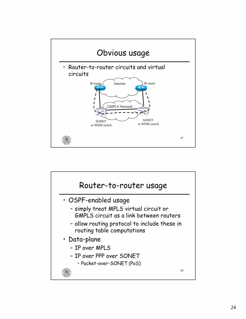
Obvious usage• Router-to-router circuits and virtual circuits
GMPLS Network
InternetIP router IP router
SONET or WDM switch
SONET or WDM switch
48
Router-to-router usage
• OSPF-enabled usage – simply treat MPLS virtual circuit or GMPLS circuit as a link between routers
– allow routing protocol to include these in routing table computations
• Data-plane– IP over MPLS– IP over PPP over SONET
• Packet-over-SONET (PoS)
25
49
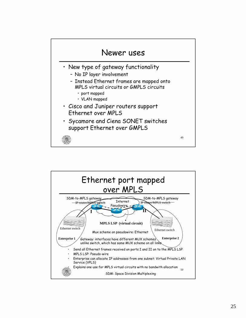
Newer uses• New type of gateway functionality
– No IP layer involvement– Instead Ethernet frames are mapped onto MPLS virtual circuits or GMPLS circuits• port mapped• VLAN mapped
• Cisco and Juniper routers support Ethernet over MPLS
• Sycamore and Ciena SONET switches support Ethernet over GMPLS
50
Ethernet port mapped over MPLS
• Send all Ethernet frames received on ports I and II on to the MPLS LSP• MPLS LSP: Pseudo-wire• Enterprise can allocate IP addresses from one subnet: Virtual Private LAN
Service (VPLS)• Explains one use for MPLS virtual circuits with no bandwith allocation
IP router/MPLS switch IP router/MPLS switch
Ethernet switch
Enterprise 1 Enterprise 2
Ethernet switch
MPLS LSP (virtual circuit)
I II
SDM-to-MPLS gateway
Pseudowire
SDM: Space Division Multiplexing
Gateway: interfaces have different MUX schemesunlike switch, which has same MUX scheme on all links
SDM-to-MPLS gateway
Mux scheme on pseudowire: Ethernet
Internet
26
51
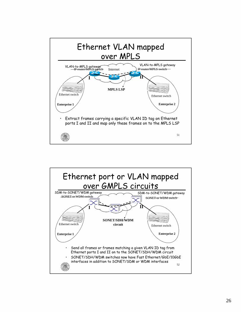
Ethernet VLAN mapped over MPLS
• Extract frames carrying a specific VLAN ID tag on Ethernet ports I and II and map only these frames on to the MPLS LSP
InternetIP router/MPLS switch IP router/MPLS switch
Ethernet switch
Enterprise 1 Enterprise 2
Ethernet switch
MPLS LSP
I II
VLAN-to-MPLS gatewayVLAN-to-MPLS gateway
52
Ethernet port or VLAN mapped over GMPLS circuits
• Send all frames or frames matching a given VLAN ID tag from Ethernet ports I and II on to the SONET/SDH/WDM circuit
• SONET/SDH/WDM switches now have Fast Ethernet/GbE/10GbE interfaces in addition to SONET/SDM or WDM interfaces
Ethernet switch
Enterprise 1 Enterprise 2
Ethernet switch
SONET/SDH/WDMcircuit
I II
SONET or WDM switch SONET or WDM switch
SDM-to-SONET/WDM gatewaySDM-to-SONET/WDM gateway
27
53
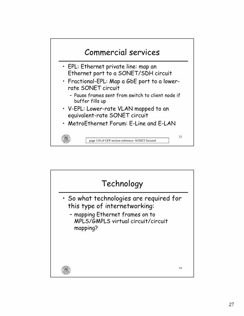
Commercial services• EPL: Ethernet private line: map an Ethernet port to a SONET/SDH circuit
• Fractional-EPL: Map a GbE port to a lower-rate SONET circuit– Pause frames sent from switch to client node if buffer fills up
• V-EPL: Lower-rate VLAN mapped to an equivalent-rate SONET circuit
• MetroEthernet Forum: E-Line and E-LAN
page 110 of GFP section reference: SONET focused
54
Technology
• So what technologies are required for this type of internetworking:– mapping Ethernet frames on to MPLS/GMPLS virtual circuit/circuit mapping?

28
55
Technologies• GMPLS networks
– Data-(user-) plane protocols • packet-switched: MPLS, VLAN Ethernet, Intserv IP• circuit-switched: SONET/SDH, WDM, SDM
– Control-plane protocols: • RSVP-TE• OSPF-TE• LMP
• Internetworking� GFP, VCAT, LCAS for SONET/SDH– PWE3 for MPLS networks– Digital wrapper for OTN
56
Why do we need Generic Framing Procedure (GFP)?
• The framing techniques used in other data-link layer protocols have problems
• For example, IP packets are carried over SONET using PPP/HDLC frames (called PoS)– HDLC inserts idle frames because SONET is synchronous it needs a constant flow of frames to avoid losing synchronization
• But, there is a problem:– HDLC uses flags for frame delineation. The issue with this framing technique is that if the flag pattern occurs in the payload, an escape byte has to be inserted
– This causes an increase in the required bandwidth– The amount of increase is payload-dependent
page 98 of reference

29
57
Other framing techniques• HEC - Header Error Control
– this is the CRC framing technique used in ATM– "A header CRC hunting mechanism is employed by the receiver to extract the ATM cells from the bit/byte synchronous stream. The HEC location is fixed and ATM cell length is fixed. Starting from the assumed cell boundary, the ATM receiver compares its computed HEC value for the assumed ATM cell header against the HEC value indicated by the assumed HEC field. Cell stream delineation is declared after positive validations of the incoming HEC fields of a few consecutive ATM cells."
• ATM cells are fixed in length, but Ethernet frames are variable-length
• Therefore, we need a length field in order to implement this HEC-based frame delineation mechanism
pages 96-97 of reference
58
Main features of the GFP protocol
• Common aspects (applicable to all client signals):– HEC + Length based delineation
• Core header has payload length and HEC– Error control: error detection
• Payload type HEC, payload Frame Check Sequence (CRC-32)– Multiplexing: linear and ring extension headers– Idle frames are sent to maintain synchronization as in HDLC
– Scrambling as in ATM: • core header + payload scrambling
– Client management - client fail signal• Client-dependent aspects:
– Client-specific encapsulation techniquespage 68 of reference
30
59
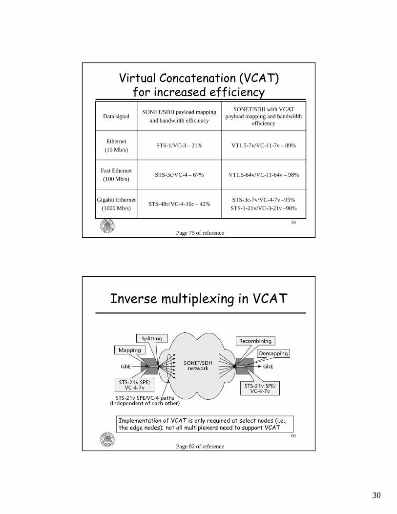
Virtual Concatenation (VCAT)for increased efficiency
Data signalSONET/SDH payload mapping
and bandwidth efficiency
SONET/SDH with VCAT payload mapping and bandwidth
efficiency
Ethernet
(10 Mb/s)STS-1/VC-3 – 21% VT1.5-7v/VC-11-7v – 89%
Fast Ethernet
(100 Mb/s)STS-3c/VC-4 – 67% VT1.5-64v/VC-11-64v – 98%
Gigabit Ethernet
(1000 Mb/s)STS-48c/VC-4-16c – 42%
STS-3c-7v/VC-4-7v –95%
STS-1-21v/VC-3-21v –98%
Page 75 of reference
60
Inverse multiplexing in VCAT
Page 82 of reference
Implementation of VCAT is only required at select nodes (i.e., the edge nodes); not all multiplexers need to support VCAT
31
61
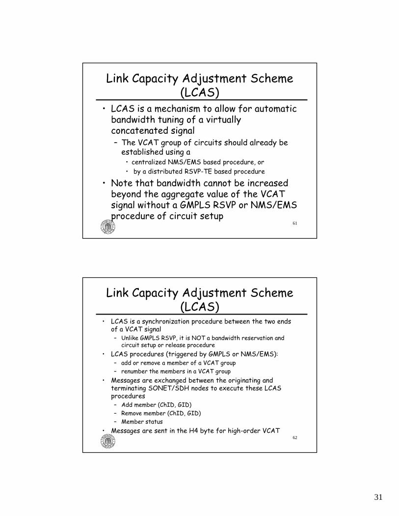
Link Capacity Adjustment Scheme (LCAS)
• LCAS is a mechanism to allow for automatic bandwidth tuning of a virtually concatenated signal– The VCAT group of circuits should already be established using a• centralized NMS/EMS based procedure, or• by a distributed RSVP-TE based procedure
• Note that bandwidth cannot be increased beyond the aggregate value of the VCAT signal without a GMPLS RSVP or NMS/EMS procedure of circuit setup
62
Link Capacity Adjustment Scheme (LCAS)
• LCAS is a synchronization procedure between the two ends of a VCAT signal– Unlike GMPLS RSVP, it is NOT a bandwidth reservation and circuit setup or release procedure
• LCAS procedures (triggered by GMPLS or NMS/EMS):– add or remove a member of a VCAT group– renumber the members in a VCAT group
• Messages are exchanged between the originating and terminating SONET/SDH nodes to execute these LCAS procedures– Add member (ChID, GID)– Remove member (ChID, GID)– Member status
• Messages are sent in the H4 byte for high-order VCAT

32
63
Technologies• GMPLS networks
– Data-(user-) plane protocols • packet-switched: MPLS, VLAN Ethernet, Intserv IP• circuit-switched: SONET/SDH, WDM, SDM
– Control-plane protocols: • RSVP-TE• OSPF-TE• LMP
• Internetworking– GFP, VCAT, LCAS for SONET/SDH� PWE3 for MPLS networks– Digital wrapper for OTN
Pseudo Wire Emulation• Pseudo Wire Emulation Edge-to-Edge (PWE3) is a mechanism for emulating certain services across a packet-switched network:– Services: Frame-relay, ATM, Ethernet, TDM services, such as SONET/SDH
– Packet-switched network:• IP• MPLS
– Common usage: Ethernet service over MPLS• Port-mapped to MPLS LSP• VLAN mapped to MPLS LSP
– IETF RFC 3985

33
65
Digital wrapper
• ITU-T G. 709 provides a method to carry Ethernet frames, ATM cells, IP datagrams directly on a WDM lightpath
66
Outline
• Principles– Different types of connection-oriented networks
• Technologies– Single network– Internetworking
�Usage– Commercial networks– Research & Education Networks (REN)

34
67
Commercial uses
• Semi-permanent MPLS virtual circuits– Traffic engineering– Voice over IP
• QoS concerns: telephony has a 150ms one-way delay requirement (with echo cancellers)
– Business or service provider interconnect • interconnecting geographically distributed campuses of an enterprise
• interconnecting wide-area routers of an ISP service provider
68
Traffic engineering (TE)• Since BGP and OSPF routing protocols mainly spread reachability information, routing tables are such that some links become heavily congested while others are lightly loaded
• MPLS virtual circuits are used to alleviate this problem– e.g., NY to SF traffic could be directed to take an MPLS virtual circuit on a lightly loaded route avoiding all paths on which more local traffic may compete
• This is an application of MPLS VCs without bandwidth allocation
35
69
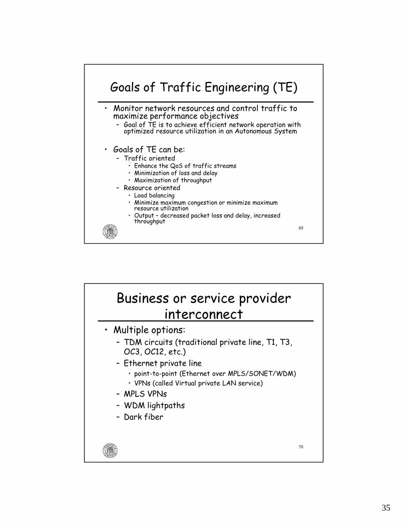
Goals of Traffic Engineering (TE)• Monitor network resources and control traffic to maximize performance objectives– Goal of TE is to achieve efficient network operation with optimized resource utilization in an Autonomous System
• Goals of TE can be:– Traffic oriented
• Enhance the QoS of traffic streams• Minimization of loss and delay• Maximization of throughput
– Resource oriented• Load balancing• Minimize maximum congestion or minimize maximum resource utilization
• Output – decreased packet loss and delay, increased throughput
70
Business or service provider interconnect
• Multiple options:– TDM circuits (traditional private line, T1, T3, OC3, OC12, etc.)
– Ethernet private line• point-to-point (Ethernet over MPLS/SONET/WDM)• VPNs (called Virtual private LAN service)
– MPLS VPNs – WDM lightpaths– Dark fiber

36
71
Dynamic circuits/virtual circuit(GMPLS control-plane)
• Commercial:– fast restoration
• circuit/VC setup delay significant– rapid provisioning
• Verizon: Bandwidth on Demand (Just-in-Time Provisioning)
• AT&T: Shared mesh networks– Customer Applications for dynamic network configuration
» Key industries: Financial, Media & Entertainment» Corporate Utility Backbone Networks (e.g. reconfigure for disaster recovery)
» Distribution of real-time content (e.g., Video)• Level3: Vyvx service
72
Research & Education(G)MPLS networks
• Internet2’s Dynamic Circuit network• NSF-funded DRAGON• DOE's ESnet - Science Data Network• DOE's Ultra Science Network (USN)• NSF-funded CHEETAH

37
Internet2 DWDM network
http://events.internet2.edu/speakers/speakers.php?go=people&id=178Rick Summerhill talk (10/11/2007)
InfineraDWDM system
http://events.internet2.edu/speakers/speakers.php?go=people&id=178Rick Summerhill talk (10/11/2007)
Internet2 Dynamic Circuit (DC) network
Ciena CD-CIEth-SONET
switch
38
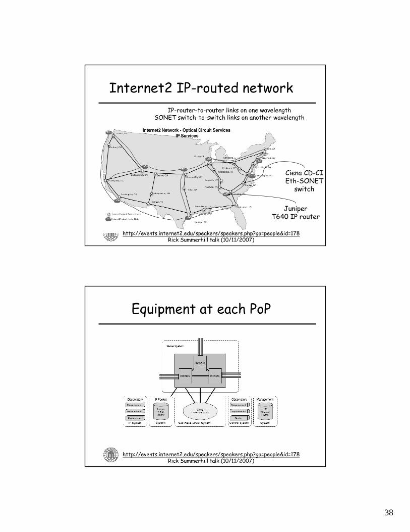
Internet2 IP-routed network
JuniperT640 IP router
IP-router-to-router links on one wavelengthSONET switch-to-switch links on another wavelength
Ciena CD-CIEth-SONET
switch
http://events.internet2.edu/speakers/speakers.php?go=people&id=178Rick Summerhill talk (10/11/2007)
Equipment at each PoP
http://events.internet2.edu/speakers/speakers.php?go=people&id=178Rick Summerhill talk (10/11/2007)
39
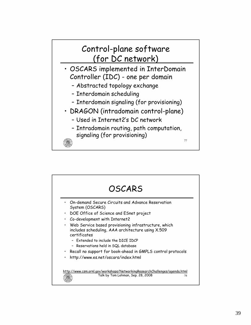
Control-plane software(for DC network)
• OSCARS implemented in InterDomain Controller (IDC) - one per domain– Abstracted topology exchange– Interdomain scheduling– Interdomain signaling (for provisioning)
• DRAGON (intradomain control-plane)– Used in Internet2’s DC network– Intradomain routing, path computation, signaling (for provisioning)
77
OSCARS• On-demand Secure Circuits and Advance Reservation
System (OSCARS)• DOE Office of Science and ESnet project• Co-development with Internet2• Web Service based provisioning infrastructure, which
includes scheduling, AAA architecture using X.509 certificates– Extended to include the DICE IDCP– Reservations held in SQL database
• Recall no support for book-ahead in GMPLS control protocols• http://www.es.net/oscars/index.html
78
http://www.csm.ornl.gov/workshops/NetworkingResearchChallenges/agenda.htmlTalk by Tom Lehman, Sep. 28, 2008
40
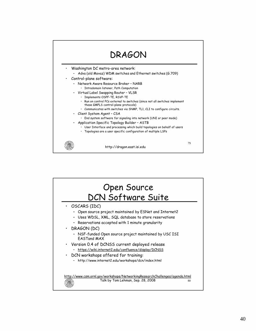
DRAGON• Washington DC metro-area network:
– Adva (old Movaz) WDM switches and Ethernet switches (G.709)• Control-plane software:
– Network Aware Resource Broker – NARB• Intradomain listener, Path Computation
– Virtual Label Swapping Router – VLSR• Implements OSPF-TE, RSVP-TE• Run on control PCs external to switches (since not all switches implement these GMPLS control-plane protocols)
• Communicates with switches via SNMP, TL1, CLI to configure circuits.– Client System Agent – CSA
• End system software for signaling into network (UNI or peer mode)– Application Specific Topology Builder – ASTB
• User Interface and processing which build topologies on behalf of users• Topologies are a user specific configuration of multiple LSPs
79http://dragon.east.isi.edu
Open Source DCN Software Suite
• OSCARS (IDC)– Open source project maintained by ESNet and Internet2– Uses WDSL, XML, SQL database to store reservations– Reservations accepted with 1 minute granularity
• DRAGON (DC)– NSF-funded Open source project maintained by USC ISI EASTand MAX
• Version 0.4 of DCNSS current deployed release– https://wiki.internet2.edu/confluence/display/DCNSS
• DCN workshops offered for training:– http://www.internet2.edu/workshops/dcn/index.html
80
http://www.csm.ornl.gov/workshops/NetworkingResearchChallenges/agenda.htmlTalk by Tom Lehman, Sep. 28, 2008

41
DICE IDCP• Dante, Internet2, CANARIE, ESNet• http://www.controlplane.net• IDCP: InterDomain Controller Protocol• wsdl - web service definition of message types and formats
• xsd – definition of schemas used for network topology descriptions and path definitions
81
http://www.csm.ornl.gov/workshops/NetworkingResearchChallenges/agenda.htmlTalk by Tom Lehman, Sep. 28, 2008
InterDomain Controller (IDC) Protocol (IDCP)
• The following organizations have implemented/deployed systems which are compatible with this IDCP– Internet2 Dynamic Circuit Network (DCN)– ESNet Science Data Network (SDN)– GÉANT2 AutoBahn System– Nortel (via a wrapper on top of their commercial DRAC System)– Surfnet (via use of above Nortel solution)– LHCNet (use of I2 DCN Software Suite)– Nysernet (use of I2 DCN Software Suite)– LEARN (use of I2 DCN Software Suite)– LONI (use of I2 DCN Software Suite)– Northrop Grumman (use of I2 DCN Software Suite)– University of Amsterdam (use of I2 DCN Software Suite)– DRAGON Network
• The following "higher level service applications" have adapted their existing systems to communicate via the user request side of the IDCP:– LambdaStation (FermiLab) – CMS project on Large Hadron Collider– TeraPaths (Brookhaven) - ATLAS project on Large Hadron Collider– Phoebus
82
http://www.csm.ornl.gov/workshops/NetworkingResearchChallenges/agenda.htmlTalk by Tom Lehman, Sep. 28, 2008

42
Heterogeneous Network TechnologiesComplex End to End Paths
End System
AS 1AS 2
AS 3
VLSR
Ethernet SegmentVLSR Established VLAN
Ethernet over WDM
Ethernet over SONET
End System
Ethernet SegmentVLSR Established VLAN
VLSR
Router MPLS LSP
IP Control Plane
IP Control Plane
IP Control Plane
Ethernet
Router
Lambda Switch
SONET Switch
http://events.internet2.edu/speakers/speakers.php?go=people&id=178Rick Summerhill talk (10/11/2007)
Example: ESNet SDNExample: Internet2 DCExample: DRAGON
IDCP operation
84
• Advance reservation request and circuit provisioning at scheduled time:• End user signals IDC with a reservation request• Authenticate requester and check authorization• Request reservation (create time, bandwidth, VLAN tag)• Signaling: creation of circuit (automatic or in response to message to IDC)
• Topology exchange: interdomain (abstracted topology information)• Monitoring
http://hpn.east.isi.edu/dice-idcp/dice-idcp-v1.0/idc-protocol-specification-may302008.doc
Route selection,admission controlcentralized per domain at IDC

43
Intra-domain operations• Using DRAGON in Internet2 DCN
– NARB does intra-domain path computation after collecting routing information by listening to OSPF-TE exchanges between VLSRs
– These intradomain paths are provided to IDC for use during resource scheduling (upto 3 path options are considered)
– 5 VLSRs serve 22 CD-CIs: “subnets of CD-CIs”– In Signaling phase, VLSR sends TL1 command to edge CD-CI, which initiates proprietary hop-by-hop signaling to configure circuit through subnet
85
86
GOLE: GLIF open lightpath exchange
44
87
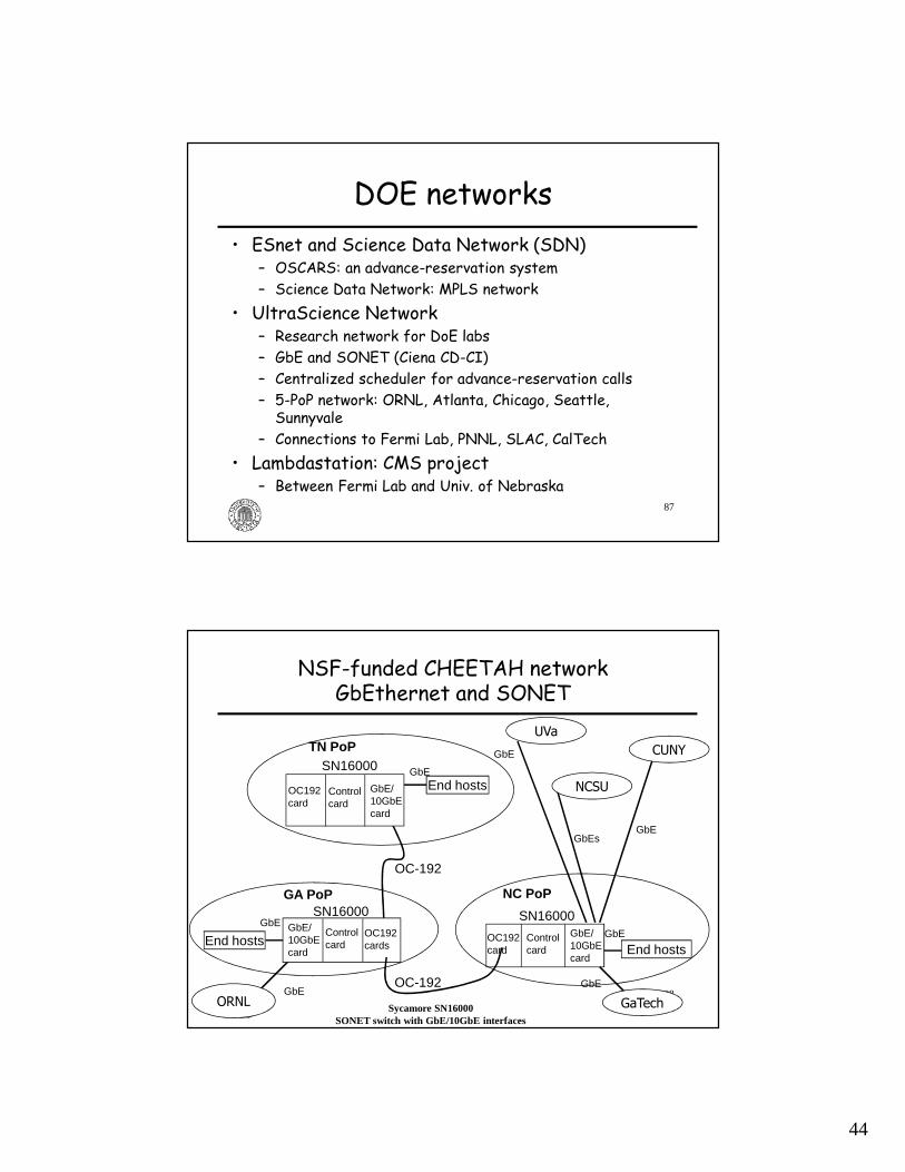
DOE networks• ESnet and Science Data Network (SDN)
– OSCARS: an advance-reservation system– Science Data Network: MPLS network
• UltraScience Network– Research network for DoE labs– GbE and SONET (Ciena CD-CI)– Centralized scheduler for advance-reservation calls– 5-PoP network: ORNL, Atlanta, Chicago, Seattle, Sunnyvale
– Connections to Fermi Lab, PNNL, SLAC, CalTech• Lambdastation: CMS project
– Between Fermi Lab and Univ. of Nebraska
88
NSF-funded CHEETAH network GbEthernet and SONET
TN PoP
Controlcard
GbE/10GbEcard
GA PoP
Controlcard
GbE/10GbEcard
SN16000
Controlcard
OC192card
OC-192
GbE/10GbEcard
End hosts
NC PoP
SN16000 SN16000
GaTech
End hosts
End hosts
ORNL
OC192cards
NCSUOC192card
OC-192
UVa
CUNYGbE
GbEGbEs
GbE
GbE
GbEGbE
GbE
Sycamore SN16000SONET switch with GbE/10GbE interfaces

45
89
Networking software
• Sycamore switch comes with built-in GMPLS control-plane protocols:– RSVP-TE and OSPF-TE
• We developed CHEETAH software for Linux end hosts:– circuit-requestor
• allows users and applications to issue RSVP-TE call setup and release messages asking for dedicated circuits to remote end hosts
– CircuitTCP (CTCP) code
http://www.ece.virginia.edu/cheetah/
90
CHEETAH network usage
Application
DNS client
RSVP-TE module
TCP/IP
CTCP/IPNIC 1
NIC 2
End Host CHEETAH software
IP-routed network
SONET circuit-switched network
CircuitGateway
CircuitGateway
Application
DNS client
RSVP-TE module
TCP/IP
CTCP/IPNIC 1
NIC 2
End HostCHEETAH software
• Bandwidth-sharing mode:• Immediate-request mode• Heterogeneous rate allocation under high loads:
• higher BW for large files than for small files• Applications:
• Common file transfers (web, P2P, CDN, storage)• attempts circuits for large files (if blocked, use IP-routed path)• use IP-routed path for small files
46
91
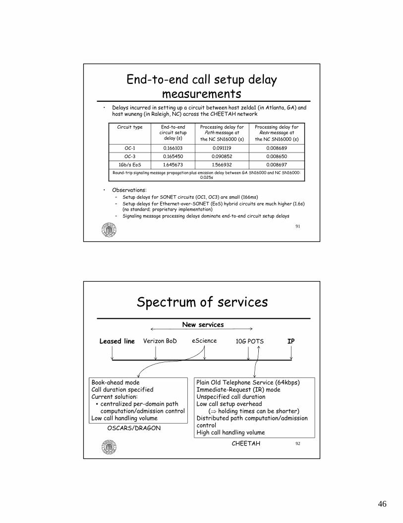
End-to-end call setup delay measurements
• Delays incurred in setting up a circuit between host zelda1 (in Atlanta, GA) and host wuneng (in Raleigh, NC) across the CHEETAH network
• Observations:– Setup delays for SONET circuits (OC1, OC3) are small (166ms) – Setup delays for Ethernet-over-SONET (EoS) hybrid circuits are much higher (1.6s)
(no standard; proprietary implementation)– Signaling message processing delays dominate end-to-end circuit setup delays
Circuit type End-to-end circuit setup delay (s)
Processing delay for Path message at
the NC SN16000 (s)
Processing delay for Resv message at
the NC SN16000 (s)
OC-1 0.166103 0.091119 0.008689
OC-3 0.165450 0.090852 0.008650
1Gb/s EoS 1.645673 1.566932 0.008697Round-trip signaling message propagation plus emission delay between GA SN16000 and NC SN16000:
0.025s
Spectrum of services
92
Leased line Verizon BoD eScience 10G POTS IP
Plain Old Telephone Service (64kbps)Immediate-Request (IR) modeUnspecified call durationLow call setup overhead
(⇒ holding times can be shorter)Distributed path computation/admission controlHigh call handling volume
Book-ahead modeCall duration specifiedCurrent solution:
• centralized per-domain path computation/admission control
Low call handling volume
New services
OSCARS/DRAGON
CHEETAH
47
93
Summary
• Principles– Different types of connection-oriented networks
• Technologies– Single network: MPLS, SONET, OTN– Internetworking: PWE3, GFP, G.709
• Usage– Commercial networks– Research & Education Networks (REN)
94
References on bandwidth sharing modes
• X. Fang and M. Veeraraghavan, “On using a hybrid architecture for file transfers,” acceptedto IEEE Transactions on Parallel and Distributed Systems, 2009.
• X. Zhu and M. Veeraraghavan, "Analysis and Design of Book-ahead Bandwidth-Sharing Mechanisms," IEEE Transactions on Communications, Dec. 08.
• X. Fang and M. Veeraraghavan, On using circuit-switched networks for file transfers,” in IEEE Globecom, New Orleans, LA, Nov. 2008.
• X. Zhu, M. E. McGinley, T. Li, and M. Veeraraghavan, "An Analytical Model for a Book-ahead Bandwidth Scheduler," in IEEE Globecom Washington, DC, Nov. 2007.
• X. Zhu, X. Zheng, and M. Veeraraghavan, "Experiences in implementing an experimental wide-area GMPLS network," IEEE Journal on Selected Areas in Communications (JSAC), Apr. 2007.
• M. Veeraraghavan, X. Fang, and X. Zheng, “On the suitability of applications for GMPLS networks,” in IEEE Globecom, San Francisco, CA, Nov. 2006.

48
95
References for OTN• ITU-T G. 872 and G.709/Y.1331 Specifications• T. Walker, “Optical Transport Network (OTN) Tutorial”,
Available online: http://www.itu.int/ITU-T/studygroups/com15/otn/OTNtutorial.pdf
• Agilent, “An overview of ITU-T G.709,” Application Note 1379
• P. Bonenfant and A. Rodriguez-Moral, "Optical Data Networking," IEEE Communications Magazine, Mar. 2000, pp. 63-70.
• E. L. Varma, S. Sankaranarayanan, G. Newsome, Z.-W. Lin, and H. Esptein, “Architecting the Services Optical Network,” IEEE Communications Magazine, Sept. 2001, pp. 80-87.
96
References for OSPF-TE• RFC 2702 - Requirements for Traffic Engineering Over MPLS:
http://www.faqs.org/rfcs/rfc2702.html• RFC 3630 - Traffic Engineering (TE) Extensions to OSPF Version 2:
http://www.faqs.org/rfcs/rfc3630.html• RFC 4203 - OSPF Extensions in Support of Generalized Multi-Protocol Label
Switching (GMPLS) : http://www.ietf.org/rfc/rfc4203.txt• RFC 2328 - OSPF Version 2 : http://www.ietf.org/rfc/rfc2328.txt• OSPFv2 Routing Protocols Extensions for ASON Routing:
http://www.ietf.org/internet-drafts/draft-ietf-ccamp-gmpls-ason-routing-ospf-02.txt
• RFC 4202 - Routing Extensions in Support of Generalized Multi-Protocol Label Switching (GMPLS): http://www.ietf.org/rfc/rfc4202.txt
• RFC 3471- Generalized Multi-Protocol Label Switching (GMPLS) Signaling Functional Description: http://www.faqs.org/rfcs/rfc3471.html
• Dimitri Papadimitriou, IETFInternet Draft, "OSPFv2 Routing Protocols Extensions for ASON Routing," draft-ietf-ccamp-gmpls-ason-routing-ospf-02.txt, October 2006.
49
97
Reference for GFP/VCAT/LCAS
• IEEE Communications Magazine, May 2002, Special issue on "Generic Framing Procedure (GFP) and Data over SONET/SDH and OTN," Guest Editors, Tim Armstrong and Steven S. Gorshe
• 6 excellent papers
98
References for REN projects• IEEE Communication Magazine special issue, March 2006– DRAGON, UltraScience Net, CHEETAH, several other projects

![The Emerging Optical Control PlaneIn the IETF, the optical control plane is referred to as Generalized Multi-Protocol Label Switching, or GMPLS [1]. Within the ITU-T, the optical control](https://img.pdfslide.net/doc/110x75/60a12bd7413e491f1d64c5b6/the-emerging-optical-control-plane-in-the-ietf-the-optical-control-plane-is-referred.jpg)