Embed Size (px)
Citation preview

User Manual
XM-720 Machine MonitorCatalog Numbers 1440-PK02-05M0, 1440-PK02-05M1, 1440-PK02-05M2
Important User InformationSolid-state equipment has operational characteristics differing from those of electromechanical equipment. Safety Guidelines for the Application, Installation and Maintenance of Solid State Controls (publication SGI-1.1 available from your local Rockwell Automation sales office or online at http://www.rockwellautomation.com/literature/) describes some important differences between solid-state equipment and hard-wired electromechanical devices. Because of this difference, and also because of the wide variety of uses for solid-state equipment, all persons responsible for applying this equipment must satisfy themselves that each intended application of this equipment is acceptable.
In no event will Rockwell Automation, Inc. be responsible or liable for indirect or consequential damages resulting from the use or application of this equipment.
The examples and diagrams in this manual are included solely for illustrative purposes. Because of the many variables and requirements associated with any particular installation, Rockwell Automation, Inc. cannot assume responsibility or liability for actual use based on the examples and diagrams.
No patent liability is assumed by Rockwell Automation, Inc. with respect to use of information, circuits, equipment, or software described in this manual.
Reproduction of the contents of this manual, in whole or in part, without written permission of Rockwell Automation, Inc., is prohibited.
Throughout this manual, when necessary, we use notes to make you aware of safety considerations.
Allen-Bradley, Rockwell Software, Rockwell Automation, XM, and TechConnect are trademarks of Rockwell Automation, Inc.DeviceNet is a trademark of the Open DeviceNet Vendor Association (ODVA).Microsoft and Windows are registered trademarks of the Microsoft Corporation.
Trademarks not belonging to Rockwell Automation are property of their respective companies.
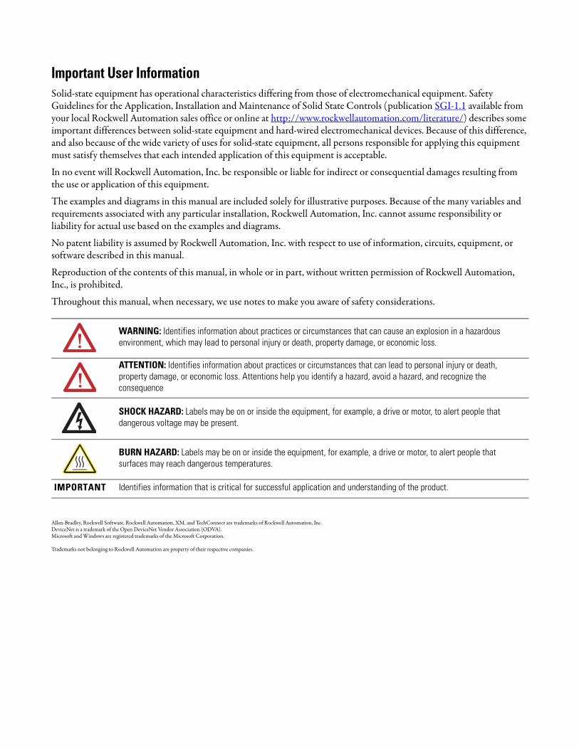
WARNING: Identifies information about practices or circumstances that can cause an explosion in a hazardous environment, which may lead to personal injury or death, property damage, or economic loss.
ATTENTION: Identifies information about practices or circumstances that can lead to personal injury or death, property damage, or economic loss. Attentions help you identify a hazard, avoid a hazard, and recognize the consequence
SHOCK HAZARD: Labels may be on or inside the equipment, for example, a drive or motor, to alert people that dangerous voltage may be present.
BURN HAZARD: Labels may be on or inside the equipment, for example, a drive or motor, to alert people that surfaces may reach dangerous temperatures.
IMPORTANT Identifies information that is critical for successful application and understanding of the product.

Table of Contents
Chapter 1Introduction Introducing the XM-720 Machine Monitor . . . . . . . . . . . . . . . . . . . . . . 5
System Description . . . . . . . . . . . . . . . . . . . . . . . . . . . . . . . . . . . . . . . . . 6Using this Manual. . . . . . . . . . . . . . . . . . . . . . . . . . . . . . . . . . . . . . . . . . . 7
Document Conventions . . . . . . . . . . . . . . . . . . . . . . . . . . . . . . . . . . 7
Chapter 2Installing the XM-720 Machine Monitor
Package Contents . . . . . . . . . . . . . . . . . . . . . . . . . . . . . . . . . . . . . . . . . . 10Installation Guidelines . . . . . . . . . . . . . . . . . . . . . . . . . . . . . . . . . . . . . . 10
Selecting a Location for the XM-720 Monitor . . . . . . . . . . . . . . . . 10Hazardous Locations . . . . . . . . . . . . . . . . . . . . . . . . . . . . . . . . . . . . 11Wiring . . . . . . . . . . . . . . . . . . . . . . . . . . . . . . . . . . . . . . . . . . . . . . . . 11
Mounting the XM-720 Monitor . . . . . . . . . . . . . . . . . . . . . . . . . . . . . . 11Mounting Dimensions . . . . . . . . . . . . . . . . . . . . . . . . . . . . . . . . . . . 11Cutout Dimension . . . . . . . . . . . . . . . . . . . . . . . . . . . . . . . . . . . . . . 12Mounting the XM-720 Monitor . . . . . . . . . . . . . . . . . . . . . . . . . . . 13
Connecting Wiring for Your Monitor . . . . . . . . . . . . . . . . . . . . . . . . . . 13Terminal Block Assignments. . . . . . . . . . . . . . . . . . . . . . . . . . . . . . 14Connecting the Power Supply . . . . . . . . . . . . . . . . . . . . . . . . . . . . . 16Connecting the Relays . . . . . . . . . . . . . . . . . . . . . . . . . . . . . . . . . . . 16Connecting the Remote Relay Reset Signal . . . . . . . . . . . . . . . . . . 19Connecting the Transducers . . . . . . . . . . . . . . . . . . . . . . . . . . . . . . 19Connecting the Tachometer Signal . . . . . . . . . . . . . . . . . . . . . . . . . 28Connecting the 4-20mA Outputs . . . . . . . . . . . . . . . . . . . . . . . . . . 29Connecting the Setpoint Multiplication Switch . . . . . . . . . . . . . . . 30
Front Panel Description. . . . . . . . . . . . . . . . . . . . . . . . . . . . . . . . . . . . . 31Bargraph Meters. . . . . . . . . . . . . . . . . . . . . . . . . . . . . . . . . . . . . . . . 32BNC Connectors . . . . . . . . . . . . . . . . . . . . . . . . . . . . . . . . . . . . . . . 34LED Indicators . . . . . . . . . . . . . . . . . . . . . . . . . . . . . . . . . . . . . . . . 34Reset Switch . . . . . . . . . . . . . . . . . . . . . . . . . . . . . . . . . . . . . . . . . . . 35
Removing the XM-720 Terminal Blocks . . . . . . . . . . . . . . . . . . . . . . . 35Inserting the XM-720 Terminal Blocks . . . . . . . . . . . . . . . . . . . . . 36
Chapter 3Configuring the XM-720 Installing XM Serial Configuration Utility . . . . . . . . . . . . . . . . . . . . . . 37
Downloading a Pre-Configured Configuration File . . . . . . . . . . . . . . . 39Files to Use With Your XM-720 Monitor . . . . . . . . . . . . . . . . . . . 39Download the Configuration File to the XM-120/121/122 . . . . . 41
Editing the XM-720 Parameters . . . . . . . . . . . . . . . . . . . . . . . . . . . . . . 44Transducer Parameters . . . . . . . . . . . . . . . . . . . . . . . . . . . . . . . . . . 44gSE Parameters . . . . . . . . . . . . . . . . . . . . . . . . . . . . . . . . . . . . . . . . 45Alarm Parameters. . . . . . . . . . . . . . . . . . . . . . . . . . . . . . . . . . . . . . . 46Relay Parameters . . . . . . . . . . . . . . . . . . . . . . . . . . . . . . . . . . . . . . . 484-20mA Output Parameters . . . . . . . . . . . . . . . . . . . . . . . . . . . . . . 50Tachometer Parameters. . . . . . . . . . . . . . . . . . . . . . . . . . . . . . . . . . 51
3 Publication GMSI10-UM001C-EN-E - June 2011
Table of Contents 4
Appendix ASpecifications . . . . . . . . . . . . . . . . . . . . . . . . . . . . . . . . . . . . . . . . . . . . . . . . . . . . . . . . . 53
Appendix BComparing Connections Between the 5802 and the XM-720
Power Supply & Relay Connections . . . . . . . . . . . . . . . . . . . . . . . . . . . 57Signal Conditioner Connections . . . . . . . . . . . . . . . . . . . . . . . . . . . . . . 58
Glossary . . . . . . . . . . . . . . . . . . . . . . . . . . . . . . . . . . . . . . . . . . . . . . . . . . . . . . . . . 59
Index . . . . . . . . . . . . . . . . . . . . . . . . . . . . . . . . . . . . . . . . . . . . . . . . . . . . . . . . . 63
Publication GMSI10-UM001C-EN-E - June 2011

Chapter 1
Introduction
This chapter provides an overview of the XM-720 Machine Monitor. It also discusses the components of the monitor.
The XM-720 Machine Monitor is referred to as XM-720 or monitor throughout this manual.
Introducing the XM-720 Machine Monitor
The XM-720 monitor is a 2-channel machine monitor designed for monitoring the condition of fans, pumps, motors, turbines, gear drives, and other machines. The XM-720 is designed to be used with accelerometers, velocity and non-contact sensors. It samples inputs, compares them to threshold values, performs self-test routines, and provides outputs to bargraph displays, relays, and LED indicator lights.
There are three variations of the XM-720 Machine Monitor:
Table 1.1 XM-720 Machine Monitor
For information about See page
Introducing the XM-720 Machine Monitor 5
System Description 6
Using this Manual 7
Catalog Number Measures Includes the following XM Modules
1440-PK02-05M0 Standard dynamic vibration XM-120 Dynamic Measurement Module
XM-441 Expansion Relay Module
1440-PK02-05M1 Low frequency dynamic vibration XM-121 Low Frequency Dynamic Measurement Module
XM-441 Expansion Relay Module
1440-PK02-05M2 gSE™ vibration XM-122 gSE Vibration Module
XM-441 Expansion Relay Module
5 Publication GMSI10-UM001C-EN-E - June 2011

6 Introduction
Figure 1.1 XM-720 Front and Side View
Each monitor offers:
• two vibration transducer connections (eddy current probes, accelerometers, velocity sensors, AC voltage output or DC voltage output measurement devices)
• one tachometer input signal connection• remote relay reset connection• three relays available for module or transducer fault, warning and trip• isolated 4-20mA per channel into a maximum load of 250 ohm• three buffered output signals on the front panel BNC connectors• two front panel digital meters • four front panel LED indicators (module, transducer, warning, and trip
status)
System Description The concept of machine monitoring is quite simple. During normal operation, the machine’s "vital signs" remain within relatively narrow ranges. If a mechanical problem develops, it will be reflected as a change in one or more of these vital signs. This change will be detected by the XM-720 and cause an alarm.
The monitoring system consists of a number of transducers connected to the XM-720. The transducers installed on the machine convert the "vital signs" to electrical signals that are transmitted to the XM-720 monitor.
The XM-720 accepts the signals from the transducers, processes and measures the signals, and closes electrical relay contacts if one of the signals increases too much. The relays can be connected to annunciators or to automatic machine controls.
1 2 3 4 5 6 7 8 9 100
16171819 2021222324252627282930313233
343536373839404142434445464748495051
1112131415 1 2 3 4 5 6 7 8 9 100
16171819 2021222324252627282930313233
343536373839404142434445464748495051
1112131415
Warning
Trip
ModuleFault
XdcrFault
Reset
TachoCH 2CH 1
% 0
25
50
75
%
100
0
25
50
75
100
XM-120/121/122 module XM-441 module
Publication GMSI10-UM001C-EN-E - June 2011

Introduction 7
Using this Manual This manual introduces you to the XM-720 Machine Monitor. It is intended for anyone who installs, configures, or uses the XM-720 monitor.
Document Conventions
There are several document conventions used in this manual, including the following:
The XM-720 Machine Monitor is referred to as XM-720 or monitor throughout this manual.
TIP A tip indicates additional information which may be helpful.
EXAMPLE This convention presents an example.
Publication GMSI10-UM001C-EN-E - June 2011

8 Introduction
Publication GMSI10-UM001C-EN-E - June 2011

Chapter 2
Installing the XM-720 Machine Monitor
This chapter discusses how to install and wire the XM-720 monitor. It also describes the front panel of the monitor.
For information about See page
Package Contents 10
Installation Guidelines 10
Mounting the XM-720 Monitor 11
Connecting Wiring for Your Monitor 13
Front Panel Description 31
Removing the XM-720 Terminal Blocks 35
ATTENTION Environment and Enclosure
This equipment is intended for use in a Pollution Degree 2 Industrial environment, in overvoltage Category II applications (as defined in IEC publication 60664–1), at altitudes up to 2000 meters without derating.
This equipment is supplied as “open type” equipment. It must be mounted within an enclosure that is suitably designed for those specific environmental conditions that will be present, and appropriately designed to prevent personal injury resulting from accessibility to live parts. The interior of the enclosure must be accessible only by the use of a tool. Subsequent sections of this publication may contain additional information regarding specific enclosure type ratings that are required to comply with certain product safety certifications.
See NEMA Standards publication 250 and IEC publication 60529, as applicable, for explanations of the degrees of protection provided by different types of enclosures.
9 Publication GMSI10-UM001C-EN-E - June 2011

10 Installing the XM-720 Machine Monitor
Package Contents The XM-720 monitor is shipped with the following items:
• Monitor
Table 2.1 XM-720 Monitor
• USB-style RS-232 serial cable
• XM Documentation and Configuration Utility CD-ROM disk, which contains the manuals, XM Serial Configuration Utility software, Hazardous Locations installation drawings, and XM-720 configuration files.
• Meter caption sheet
• Mounting template sheet
Installation Guidelines Selecting a Location for the XM-720 Monitor
The XM-720 monitor is designed for panel mounting in a control room or local mounting in an enclosure for ready access to the front panel by operating personnel. When selecting a location for the monitor, keep in mind that it is a complex electronic device. It is designed and manufactured to withstand quite severe environmental conditions, but as with any electronic equipment, it will give the longest, trouble-free service if treated with care.
The selected location should not subject the monitor to dripping water from above, or to heat from equipment installed beneath it.
Cat. No. XM Measurement Module
1440-PK02-05M0 XM-120 Standard Dynamic Vibration Module
1440-PK02-05M1 XM-121 Low Frequency Dynamic Vibration Module
1440-PK02-05M2 XM-122 gSE™ Vibration Module
IMPORTANT This product is an open type component and shall be installed in a suitable grounded enclosure accepted by local authority having jurisdiction.
Publication GMSI10-UM001C-EN-E - June 2011

Installing the XM-720 Machine Monitor 11
Hazardous Locations
Due to the proximity of some control rooms to process machinery, the control room interior may be designated as a hazardous area within the definition of Article 500 of the (U.S.) National Electrical Code, or similar codes in other countries.
If the control room is classified as a Division 2 area (N.E.C.), present interpretation of the code usually permits the operation of electrical equipment if two conditions are met during normal operation:
1. Arcing or sparking contacts must not be exposed, and
2. No surface temperature may exceed 80% of the ignition temperature (in °C) of the hazardous gas or vapor.
The XM-720 monitor meets the first requirement since all relay contacts are hermetically sealed. The second requirement is met if ignition temperature of the hazardous gas or vapor is above 200°C (392°F).
Wiring
Use solid or stranded wire. All wiring should meet the following specifications:
• 12 to 28 AWG (0.08 to 2.5 mm2)
• Recommended strip length 8 to 9 millimeters (0.33 inches)
Mounting the XM-720 Monitor
The XM-720 monitor is designed for installation in a wall, panel cutout, or custom enclosure.
Mounting Dimensions
Figure 2.1 shows the dimensions of the XM-720 monitor, as well as the reduced scale cutout. Use this to make sure you have adequate space to install your monitor. All measurements are in inches [mm].
ATTENTION See the XM Documentation and Configuration Utility CD for Hazardous Locations installation drawings. The XM Documentation and Configuration Utility CD is packaged with the XM-720.
Publication GMSI10-UM001C-EN-E - June 2011

12 Installing the XM-720 Machine Monitor
Figure 2.1 Mounting Dimensions and Side View
Cutout Dimension
Use the full size template shipped with the XM-720 monitor to mark the cutout dimensions. The figure below shows a reduced scale cutout.
Figure 2.2 Cutout Dimensions
1 2 3 4 5 6 7 8 9 100
16171819 2021222324252627282930313233
343536373839404142434445464748495051
1112131415 1 2 3 4 5 6 7 8 9 100
16171819 2021222324252627282930313233
343536373839404142434445464748495051
1112131415
1/4" MOUNTINGSCREWS 4 PLACES
KNOCKOUTS FOR 3/4"CONDUIT FITTINGSLOCATED IN TOP OF CASE.
FRONT PANEL
PANELCUTOUT
7.25 [184.15mm]
7.75 [196.85mm]
4.650 [118.11mm] Ø.264 PLACES
Publication GMSI10-UM001C-EN-E - June 2011

Installing the XM-720 Machine Monitor 13
Mounting the XM-720 Monitor
Mount the monitor to the panel using four 1/4 inch mounting screws (not included in shipment).
1. Cut an opening in the panel and drill four holes for the mounting screws using the cutout template provided with the XM-720 monitor. Remove sharp edges or burrs.
2. Slide the XM-720 monitor through the opening.
3. Install and alternately tighten the mounting screws until the monitor is held firmly against the panel.
Connecting Wiring for Your Monitor
Wiring to the monitor is made through the two-single row, removable terminal blocks located on the back panel of the XM-720 monitor. See Figure 2.3
Figure 2.3 XM-720 Back Panel
ATTENTION • Disconnect all electrical power from the panel before making cutout.
• Make sure area around the panel cutout is clear.• Take precautions so that metal cuttings do not enter any
components already installed in panel• Failure to follow this warning may result in personal
injury or damage to the panel components.
IMPORTANT If you are installing the XM-720 monitor in an existing cutout, skip to step 2.
9 16151411 1312107 8654NLE
25 32313027 28 292621 23 242220191817
Removable Terminal Blocks (RTB)
Terminal Block (TB) 1
Terminal Block (TB) 2
Publication GMSI10-UM001C-EN-E - June 2011

14 Installing the XM-720 Machine Monitor
The XM-720 terminal blocks have spring clamp connectors. Follow these steps to connect wiring to the back panel connectors.
1. Insert a 1/8" [3.5 mm] wide blade-type screwdriver into the slot above the selected wiring port.
2. Insert the wire into the open terminal while holding the screwdriver up.
3. Remove the drive blade to secure the wire.
Terminal Block Assignments
The terminal block assignments and descriptions for the XM-720 monitor are shown in Table 2.2.
IMPORTANT The XM-720 terminal plugs are keyed so they will only fit into the corresponding socket. Be certain that you are connecting the wires to the correct connectors.
WARNING EXPLOSION HAZARD
Do not disconnect equipment unless power has been removed or the area is known to be nonhazardous. Do not disconnect connections to this equipment unless power has been removed or the area is known to be nonhazardous. Secure any external connections that mate to this equipment by using screws, sliding latches, threaded connectors, or other means provided with this product.
Publication GMSI10-UM001C-EN-E - June 2011

Installing the XM-720 Machine Monitor 15
Table 2.2 Terminal Block Assignments
1 It is assumed that the relay is to be configured as failsafe.
2. It is assumed that the relay is to be configure as non-failsafe.
Terminal Block
No. Name Description
TB1(top)
E AC Earth Ground AC equipment earth ground
L AC Input Line AC power (hot)
N AC Input Neutral AC common (neutral)
4 Fault Relay NC 1 Normally Closed contact for Module/Transducer Fault relay
5 Fault Relay Common Common for Module/Transducer Fault relay
6 Fault Relay NO 1 Normally Open contact for Module/Transducer Fault relay
7 Warning Relay NO 2 Normally Open contact for Warning relay
8 Warning Relay Common Common for Warning relay
9 Warning Relay NC 2 Normally Closed contact for Warning relay
10 Trip Relay NO 2 Normally Open contact for Trip relay
11 Trip Relay Common Common for Trip relay
12 Trip Relay NC 2 Normally Closed contact for Trip relay
13 Reset Relay Switch Switch input to reset internal relays
14 Switch RTN Switch return for Reset Relay and Setpoint Multiplier switch
15 Setpoint Multiplier Switch Switch input to activate Setpoint Multiplication (active open)
16 24V Common Tachometer 24V power return
TB2(bottom)
17 Xducer 1 (+) Vibration transducer channel 1 connection
18 Xducer 1 (-) Vibration transducer channel 1 connection
19 Chassis GND Connection to chassis ground (channel 1 shield)
20 Xducer 2 (+) Vibration transducer channel 2 connection
21 Xducer 2 (-) Vibration transducer channel 2 connection
22 Chassis GND Connection to chassis ground (channel 2 shield)
23 Xducer +24V Transducer power, positive side; used to power external sensor
24 Xducer -24V Transducer power, negative side; used to power external sensor
25 4-20mA 1 (+) 3 4-20mA output; channel 1250 ohm maximum load
26 4-20mA 1 (-) 3
27 Chassis GND Connection to chassis ground (4-20mA outputs shield)
28 4-20mA 2 (+) 3 4-20mA output; channel 2250 ohm maximum load
29 4-20mA 2 (-) 3
30 Tachometer In (+) Tachometer transducer/signal input, positive side
31 Tachometer In (-) Tachometer transducer/signal input, negative side
32 Chassis GND Connection to chassis ground (tachometer shield)
Publication GMSI10-UM001C-EN-E - June 2011
16 Installing the XM-720 Machine Monitor
3 4-20mA operation requires a jumper at terminals 25 & 26 (or terminals 28 & 29) if 4-20mA output is not used. Otherwise the associated meter on front panel will not function properly. Refer to Connecting the 4-20mA Outputs on page 29 for more information.
Connecting the Power Supply
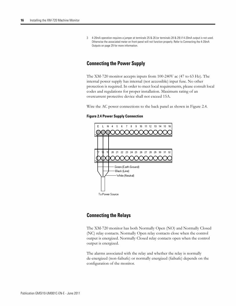
The XM-720 monitor accepts inputs from 100-240V ac (47 to 63 Hz). The internal power supply has internal (not accessible) input fuse. No other protection is required. In order to meet local requirements, please consult local codes and regulations for proper installation. Maximum rating of an overcurrent protective device shall not exceed 15A.
Wire the AC power connections to the back panel as shown in Figure 2.4.
Figure 2.4 Power Supply Connection
Connecting the Relays
The XM-720 monitor has both Normally Open (NO) and Normally Closed (NC) relay contacts. Normally Open relay contacts close when the control output is energized. Normally Closed relay contacts open when the control output is energized.
The alarms associated with the relay and whether the relay is normally de-energized (non-failsafe) or normally energized (failsafe) depends on the configuration of the monitor.
Publication GMSI10-UM001C-EN-E - June 2011

Installing the XM-720 Machine Monitor 17
The XM-720 back panel terminal block is equipped with three single-pole, double-throw relays. Figures 2.5 to 2.7 show the connection for the three relays.
Module/Transducer Fault Relay
In the provided configuration files, the Fault relay is configured to be a failsafe relay and is set up to activate if any one of the conditions occurs:
• There is a hardware or firmware failure.• A transducer fault is detected on the associated transducer.
You can change the alarms associated with this relay as well as the behavior of the relay using the XM Serial Configuration Utility. Refer to Editing the XM-720 Parameters on page 44 for more information.
Figure 2.5 shows the on-board relay connection for the Fault relay.
Figure 2.5 Wiring Connection for Fault Relay (Failsafe)
Warning Relay
In the provided configuration files, the Warning relay is configured to activate when the overall measurement in either channel exceeds the alert threshold levels (same conditions that activate the Warning LED). This relay is configured as a non-failsafe relay. Figure 2.6 shows the on-board relay connection for the Warning relay.
The alert threshold levels and the behavior of the relay can be changed using the XM Serial Configuration Utility. Refer to Editing the XM-720 Parameters on page 44.
Shown with power on and no fault
Publication GMSI10-UM001C-EN-E - June 2011

18 Installing the XM-720 Machine Monitor
Figure 2.6 Wiring Connection for Warning Relay (Non-failsafe)
Trip Relay
In the provided configuration files, the Trip relay is configured to activate when the overall measurement in either channel exceeds the danger threshold level (same conditions that activate the Trip LED). This relay is also configured as a non-failsafe relay. Figure 2.7 shows the on-board relay connection for the Trip relay.
The danger threshold level and the behavior of the relay can be changed using the XM Serial Configuration Utility. Refer to Editing the XM-720 Parameters on page 44.
Figure 2.7 Wiring Connection for Trip Relay (Non-failsafe)
Publication GMSI10-UM001C-EN-E - June 2011
Installing the XM-720 Machine Monitor 19
Connecting the Remote Relay Reset Signal
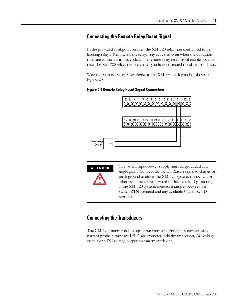
In the provided configuration files, the XM-720 relays are configured to be latching relays. This means the relays stay activated even when the condition that caused the alarm has ended. The remote relay reset signal enables you to reset the XM-720 relays remotely after you have corrected the alarm condition.
Wire the Remote Relay Reset Signal to the XM-720 back panel as shown in Figure 2.8.
Figure 2.8 Remote Relay Reset Signal Connection
Connecting the Transducers
The XM-720 monitor can accept input from any Entek non-contact eddy current probe, a standard IEPE acclerometer, velocity transducer, AC voltage output or a DC voltage output measurement device.
ATTENTION The switch input power supply must be grounded at a single point. Connect the Switch Return signal to chassis or earth ground at either the XM-720 system, the switch, or other equipment that is wired to this switch. If grounding at the XM-720 system, connect a jumper between the Switch RTN terminal and any available Chassis GND terminal.
Publication GMSI10-UM001C-EN-E - June 2011

20 Installing the XM-720 Machine Monitor
The sensitivity, operating range, and power requirements have been predefined in the provided configuration files. The characteristics of the transducer and the signal processing performed on the input signals can be changed using the XM Serial Configuration Utility. Refer to Transducer Parameters on page 44.
Setting the Buffer Range for the Transducer
The XM-720 provides buffered outputs of all transducer input signals through the BNC connectors on the front panel.
The voltage operating range of the buffered outputs must be configured to coincide with the corresponding transducer bias range. This operating range is configured by placing a jumper from terminal 5 (channel 1) and terminal 22 (channel 2) to terminal 6 (Positive Buffer Bias) or terminal 21 (Buffer -) on the XM-120/121/122 module, depending on the transducer. The buffered output operating range is configured independently per channel.
Table 2.3 Configuring Buffered Output Operating Range
IMPORTANT The 1440-PK02-05M2 (gSE) monitor can measure both "standard" vibration, similarly to the 1440-PK02-05M0, and g’s Spike Energy™ (gSE). It can produce the gSE measurement only with an IEPE accelerometer or externally powered sensor.
Transducer Input Range Channel Connect XM-12x Terminal
To XM-12x Terminal
Negative Bias -24 to +9V 1 5 21
2 22 21
Positive Bias -5 to +24V 1 5 6
2 22 6
Non-Bias -5 to +9V 1 ---- ----
2 ---- ----
Publication GMSI10-UM001C-EN-E - June 2011

Installing the XM-720 Machine Monitor 21
IMPORTANT By default, both buffered outputs have been wired for a positive bias transducer (accelerometer and powered sensor). This means that orange jumper wires have been supplied on the XM-120/121/122 terminal block between terminals 5, 6, and 22 (see Figure 2.9).
Figure 2.9 Jumpers for buffer input wiring
If the transducer is not a positive bias transducer, follow these guidelines:
• For a non-contact sensor, remove the orange jumper between terminals 5 and 6 (terminals 22 and 6 for channel 2) and install it between terminals 5 and 21 (terminals 22 and 21 for channel 2).
• For a non-bias sensor, such as a velocity sensor, remove the orange jumper between terminals 5 and 6 (terminals 22 and 6 for channel 2).
Refer to Table 2.3 for details. Refer to the XM Users Guide for more information about the XM-120/121/122 module.
1 2 3 4 5 6 7 8 9 100
16171819 2021222324252627282930313233
343536373839404142434445464748495051
1112131415 1 2 3 4 5 6 7 8 9 100
16171819 2021222324252627282930313233
343536373839404142434445464748495051
1112131415
1 2 3 4 5 6 7 8 9 100
16171819 2021222324252627282930313233
343536373839404142434445464748495
1112131415
Orange jumpers for buffer outputs
Publication GMSI10-UM001C-EN-E - June 2011

22 Installing the XM-720 Machine Monitor
Connecting an IEPE Accelerometer
The following figure shows the wiring of an IEPE accelerometer to the XM-720 back panel.
IMPORTANT You may ground the cable shield at either end of the cable. Do not ground the shield at both ends. Recommended practice is to ground the cable shield to one of the Chassis GND terminals on the XM-720 terminal block and not at the transducer. Any of the Chassis GND terminals on the XM-720 terminal block provides a grounding point for the cable shield.
IMPORTANT The internal transducer power supply is providing power to the IEPE accelerometer.
IMPORTANT Using the XM Serial Configuration Utility, make certain the IEPE Power parameter is enabled. Refer to Transducer Parameters on page 44.
IMPORTANT A jumper from terminals 5 to 6 on the XM-120/121/122 terminal block is required for channel 1 buffered output. A jumper from terminals 22 to 6 on XM-120/121/122 terminal block is required for channel 2 buffered output. Refer to Setting the Buffer Range for the Transducer on page 20.
Publication GMSI10-UM001C-EN-E - June 2011

Installing the XM-720 Machine Monitor 23
Figure 2.10 IEPE Accelerometer Wiring
Connecting a Non-Contact Sensor
The figure below show the wiring of a non-contact sensor to the XM-720 back panel.
TYPICAL WIRING FOR IEPE ACCELEROMETER TO XM-720 BACK PANEL
Shield
Channel 1 Input SignalSignal Common
Shield
Channel 2 Input Signal
171819
202122
Signal Common
Pin A - SignalPin B - Common
Cable shield notconnected at this end
Pin A - SignalPin B - Common
Cable shield notconnected at this end
IMPORTANT You may ground the cable shield at either end of the cable. Do not ground the shield at both ends. Recommended practice is to ground the cable shield to one of the Chassis GND terminals on the XM-720 terminal block and not at the transducer. Any of the Chassis GND terminals on the XM-720 terminal block provides a grounding point for the cable shield.
IMPORTANT The internal transducer power supply is providing power to the IEPE accelerometer.
Publication GMSI10-UM001C-EN-E - June 2011

24 Installing the XM-720 Machine Monitor
Figure 2.11 Non-Contact Sensor Wiring
IMPORTANT Using the XM Serial Configuration Utility, make certain the IEPE Power parameter is disabled. Refer to Transducer Parameters on page 44.
IMPORTANT A jumper from terminal 5 to 21 on the XM-120/121/122 terminal block is required for channel 1 buffered output. A jumper from terminal 22 to 21 on XM-120/121/122 terminal block is required for channel 2 buffered output. Refer to Setting the Buffer Range for the Transducer on page 20.
TYPICAL WIRING FOR NON-CONTACT SENSORTO XM-720 BACK PANEL
COMSIG-24
ShieldFloating
171819
202122
24
Signal CommonChannel 2 Input Signal
Shield
-24V DC
COMSIG-24
ShieldFloating
24
Channel 1 Input SignalSignal CommonShield
-24V DC
Publication GMSI10-UM001C-EN-E - June 2011

Installing the XM-720 Machine Monitor 25
Connecting a Passive Transducer
The figure below shows the wiring of a passive transducer, such as a coil-based velocity sensor, to the XM-720 back panel.
IMPORTANT You may ground the cable shield at either end of the cable. Do not ground the shield at both ends. Recommended practice is to ground the cable shield to one of the Chassis GND terminals on the XM-720 terminal block and not at the transducer. Any of the Chassis GND terminals on the XM-720 terminal block provides a grounding point for the cable shield.
IMPORTANT The module does not power the sensor. It measures only the input voltage.
IMPORTANT Using the XM Serial Configuration Utility, make certain the IEPE Power parameter is disabled. Refer to Transducer Parameters on page 44.
IMPORTANT No jumper is required for buffered outputs on the XM-120/121/122 terminal block. Remove any jumpers between terminals 5, 6, 21, and 22 on the XM-120/121/122 terminal block. Refer to Setting the Buffer Range for the Transducer on page 20.
Publication GMSI10-UM001C-EN-E - June 2011

26 Installing the XM-720 Machine Monitor
Figure 2.12 Velocity Sensor Wirings
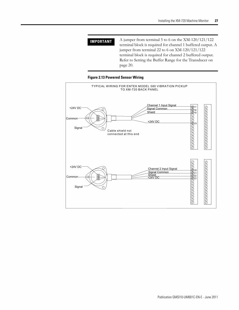
Connecting a Powered Sensor
The figure below shows the wiring of a powered sensor, such as Entek IRD Model 544 or 580 Vibration Pickup, to the XM-720 back panel.
TYPICAL WIRING FOR COIL-BASED VELOCITY SENSOR TO XM-720 BACK PANEL
Shield
Channel 1 Input SignalSignal Common
Shield
Channel 2 Input Signal
171819
202122
Signal Common
Pin A - SignalPin B - Common
Cable shield notconnected at this end
Pin A - SignalPin B - Common
Cable shield notconnected at this end
IMPORTANT You may ground the cable shield at either end of the cable. Do not ground the shield at both ends. Recommended practice is to ground the cable shield to one of the Chassis GND terminals on the XM-720 terminal block and not at the transducer. Any of the Chassis GND terminals on the XM-720 terminal block provides a grounding point for the cable shield.
IMPORTANT Using the XM Serial Configuration Utility, make certain the IEPE Power parameter is disabled. Refer to Transducer Parameters on page 44.
Publication GMSI10-UM001C-EN-E - June 2011
Installing the XM-720 Machine Monitor 27
Figure 2.13 Powered Sensor Wiring
IMPORTANT A jumper from terminal 5 to 6 on the XM-120/121/122 terminal block is required for channel 1 buffered output. A jumper from terminal 22 to 6 on XM-120/121/122 terminal block is required for channel 2 buffered output. Refer to Setting the Buffer Range for the Transducer on page 20.
+24V DC
Common
Signal
TYPICAL WIRING FOR ENTEK MODEL 580 VIBRATION PICKUP
TO XM-720 BACK PANEL
Cable shield notconnected at this end
171819
202122
23
Channel 1 Input SignalSignal CommonShield
+24V DC
+24V DC
Signal
Common23
Channel 2 Input SignalSignal CommonShield+24V DC
Publication GMSI10-UM001C-EN-E - June 2011
28 Installing the XM-720 Machine Monitor
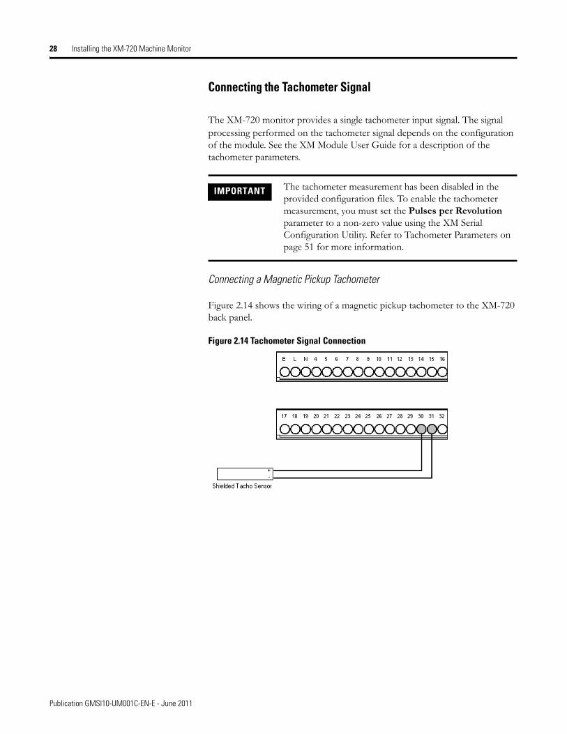
Connecting the Tachometer Signal
The XM-720 monitor provides a single tachometer input signal. The signal processing performed on the tachometer signal depends on the configuration of the module. See the XM Module User Guide for a description of the tachometer parameters.
Connecting a Magnetic Pickup Tachometer
Figure 2.14 shows the wiring of a magnetic pickup tachometer to the XM-720 back panel.
Figure 2.14 Tachometer Signal Connection
IMPORTANT The tachometer measurement has been disabled in the provided configuration files. To enable the tachometer measurement, you must set the Pulses per Revolution parameter to a non-zero value using the XM Serial Configuration Utility. Refer to Tachometer Parameters on page 51 for more information.
Publication GMSI10-UM001C-EN-E - June 2011

Installing the XM-720 Machine Monitor 29
Connecting a Hall Effect Tachometer Sensor
Figure 2.15 shows the wiring of a Hall Effect Tachometer Sensor, Cat. No. 44393, to the XM-720 back panel.
Figure 2.15 Hall Effect Tachometer Signal Connection
Connecting the 4-20mA Outputs
The XM-720 monitor includes an isolated 4-20mA per channel output into a maximum load of 250 ohms. In the provided configuration files, the 4-20mA output signals track the overall measurement, and the Min and Max range is set according to the type of transducer.
The measurements that the 4-20mA tracks and the signal levels that correspond to the 4mA and 20mA can be changed using the XM Serial Configuration Utility. Refer to 4-20mA Output Parameters on page 50 for details.
Wire the 4-20mA outputs to the XM-720 back panel as shown in Figure 2.16.
Publication GMSI10-UM001C-EN-E - June 2011

30 Installing the XM-720 Machine Monitor
Figure 2.16 4-20mA Output Connections
Connecting the Setpoint Multiplication Switch
You can configure the XM-720 monitor to multiply the alarm setpoints, or inhibit the alarms during the start-up period. This can be used to avoid alarm conditions that may occur during startup, for example, when the monitored machine passes through a critical speed.
The startup period and the action to take when the setpoint multiplier switch is closed in predefined in the provided configuration files. These settings can be changed using the XM Serial Configuration Utility. Refer to Alarm Parameters on page 46.
Wire the Setpoint Multiplication switch to the XM-720 back panel as shown in Figure 2.17.
ATTENTION The 4-20mA outputs must be grounded at a single point. Connect the 4-20mA Return signal to chassis ground at the XM-720 end through the 4-20mA (-) terminal. Do not ground the 4-20mA return elsewhere.
ATTENTION If a 4-20mA output is not used, a jumper must be wired between the unused 4-20mA terminals (terminals 25 and 26 for channel 1; terminals 28 and 29 for channel 2), otherwise the associated meter on the front panel will not function properly.
Channel 2 4-20mA output is not being used. Therefore a jumper from terminal 28 to 29 is required.
Publication GMSI10-UM001C-EN-E - June 2011

Installing the XM-720 Machine Monitor 31
Figure 2.17 Setpoint Multiplication Connection
Front Panel Description The XM-720 monitor front panel consists of four LEDs, two easy to read digital meters, three BNC connectors and a Reset Relay switch.
Figure 2.18 XM-720 Front Panel
ATTENTION The switch input power supply must be grounded at a single point. Connect the Switch Return signal to chassis or earth ground at either the XM-720 system, the switch, or other equipment that is wired to this switch. If grounding at the XM-720 system, place a jumper between the Switch RTN terminal and any available Chassis GND terminal.
Warning
Trip
ModuleFault
XdcrFault
Reset
TachoCH 2CH 1
0
25
50
75
%
100
0
25
50
75
%
100
LED indicators
BNC connectors for output of buffered input signals
Channel 1 metershowing overall
measurement
Channel 2 metershowing overall
measurement
Relay reset switch
Publication GMSI10-UM001C-EN-E - June 2011

32 Installing the XM-720 Machine Monitor
Bargraph Meters
The XM-720 front panel has two vertical-scale meters, one for each input channel. Each meter consists of 31 solid-state lamps (light emitting diodes) arranged one above the other. Scale markings on the window appear at 3% increments, thus there is one scale mark for each of the thirty lamps.
In the provided configuration files, each meter is configured to continuously display the overall vibration level. The amplitude of the signal appears as a continuous bright light next to the one of the thirty scale marks. This simplified display makes it easy for you to recognize potential problems as the measured signal amplitude approaches one of the setpoints.
The measurement displayed in the meter, the full scale, and the alarm and trip (danger) thresholds are configurable using the XM Serial Configuration Utility. Refer to Chapter 3 for more information about the XM Serial Configuration Utility.
The XM-720 is shipped with clear self-adhesive caption sheet for customizing the meter scale. The caption stickers contain the most popular measured units and ranges. The caption sheet also contains orange and red arrows for labeling the alert and danger (trip) threshold levels.
Follow these instructions to customize the scaled face plate.
1. Remove the front bezel. To do this, insert a blade-type screwdriver between the plastic bezel frame and front panel and lift the bezel off.
2. Remove the scaled faceplate. Be careful not to scratch the clear lens.
3. Peel the desired measured units and the orange and red arrows from the caption sheet and place on the scaled faceplate. Refer to To determine placement for Alert and Danger Threshold Arrows on page 33 for an example.
4. Replace the faceplate, lens and bezel.
Publication GMSI10-UM001C-EN-E - June 2011

Installing the XM-720 Machine Monitor 33
To determine the signal amplitude on bargraph meter
To determine the signal amplitude in engineering units, use the following formula:
To determine placement for Alert and Danger Threshold Arrows
The caption sheet (included in package) contains red (danger) and orange (alert) arrows for you to place on the meter to show the alert and danger threshold levels. Use the following formula to determine placement of the arrows.
Amplitude Bargraph % 100⁄( ) 4-20mA Max Range value 4-20mA Min Range value–( ) 4-20mA Min Range value+×=
EXAMPLE meter reading: 40%4-20mA Min Range value: 0 mils4-20mA Max Range value: 5 mils
amplitude = (40% / 100) x (5 -0) + 0 = 2 mils
EXAMPLE Alert Threshold value in configuration: 2.5 g4-20mA Min Range value in configuration: 0 g4-20mA Max Range value in configuration: 5 g
Alert threshold % sticker = (2.5 - 0) x 100% / (5 - 0) = 50%
EXAMPLE Danger threshold value in configuration: 3.5 g4-20mA Min Range value in configuration: 0 g4-20mA Max Range value in configuration: 5 g
Danger threshold % sticker = (3.5 - 0) x 100% / (5 - 0) = 70%
Threshold % Threshold value 4-20mA Min Range value–( ) 100%×4-20mA Max Range value 4-20mA Min Range value–( )
----------------------------------------------------------------------------------------------------------------------------------------------=
Place the orange arrow sticker on meter to show alert threshold level (e.g. 50%).
Place the red arrow sticker on meter to show danger threshold level (e.g. 70%).
Measure units/range sticker
Publication GMSI10-UM001C-EN-E - June 2011

34 Installing the XM-720 Machine Monitor
BNC Connectors
The XM-720 front panel provides three BNC connectors directly below the bargraph meters. There are two connectors (CH1 and CH2) for monitoring the input signals. And a third BNC connector (TACHO) for phase referencing or triggering.
LED Indicators
The four LEDs on the front panel of the XM-720 monitor indicate the status of the monitor. In the provided configuration files, the LEDs are configured to function as described in Table 2.D. Use this table to help you troubleshoot your monitor.
WARNING EXPLOSION HAZARD
Do not use BNC connectors when area is known to be hazardous. BNC caps must be securely installed on ALL connectors during normal operation.
IMPORTANT Making a change to the configuration parameters may possibly change the intended function of the LED.
IMPORTANT The Module Fault LED will be illuminated when you first apply power to the XM-720 monitor because the relay associated with this LED is not configured for failsafe. Make sure you configure your XM-720. For information on how to configure the XM-720, see Chapter 3 on page 37.
Table 2.D LED Description
LED State Indicates
Trip Off Normal condition
On The current overall measurement in either channel is in excess of the danger level thresholds.
Warning Off Normal condition
On The current overall measurement in either channel is in excess of either the alert level thresholds or the danger level thresholds.
Publication GMSI10-UM001C-EN-E - June 2011

Installing the XM-720 Machine Monitor 35
Reset Switch
The XM-720 front panel has an external reset switch located above the LED indicators (see Figure 2.18). The switch can be used to reset all latched relays and LEDs on the front panel of the XM-720 monitor. To reset the relays and LED indicators, press and release the Reset button.
Removing the XM-720 Terminal Blocks
The XM-720 monitor has two removable terminal blocks (RTB) on the back panel.
Removing the XM-720 Terminal Blocks
Module Fault
Off Normal condition
On • A hardware or firmware failure is preventing proper operation of the device.
• Relay #1 is not configured to be failsafe. Typically this occurs on new installations, in which the XM-720 has not been configured. Refer to Chapter 3 on page 37 for information on how to configure the XM-720.
Xdcr Fault Off Normal condition
On The transducer DC bias in either channel is out-of-range.
IMPORTANT The Reset switch resets the relays only if the input is no longer in alarm or the condition that caused the alarm is no longer present.
TIP In the provided configuration files, the XM-720 relays are configured to be latching relays. This means the relays stay activated even when the condition that caused the alarm has ended.
Table 2.D LED Description
LED State Indicates
WARNING When you connect or disconnect the RTB with field side power, an electrical arc can occur. This could cause an explosion in hazardous location installations.
Be sure that power is removed or the area is nonhazardous before proceeding.
Publication GMSI10-UM001C-EN-E - June 2011

36 Installing the XM-720 Machine Monitor
To remove the XM-720 terminal blocks, grasp the terminal block with your thumb and forefinger and pull straight out.
Inserting the XM-720 Terminal Blocks
Insert the terminal block by aligning it and pushing it firmly onto the connector contacts.
WARNING When you connect or disconnect the RTB with field side power, an electrical arc can occur. This could cause an explosion in hazardous location installations.
Be sure that power is removed or the area is nonhazardous before proceeding.
IMPORTANT The XM-720 terminal plugs are keyed so they will only fit into the corresponding socket.
Publication GMSI10-UM001C-EN-E - June 2011

Chapter 3
Configuring the XM-720
This chapter provides information to help you configure your XM-720 monitor using the XM Serial Configuration Utility software. Refer to the XM User Guide for a complete listing and description of the configuration parameters.
Please refer to the online help and the XM Serial Configuration Utility Getting Results Guide (publication XMSCU-GR002) for assistance on how to use the XM Serial Configuration Utility software.
Installing XM Serial Configuration Utility
The XM Serial Configuration Utility is a 32-bit Windows application program that allows you to configure and view live data from any XM module.
The XM Serial Configuration Utility runs as a stand-alone program on a computer connected directly to an XM module through a special cable (included with the XM-720). The cable connects to the computer’s serial port and to a mini-connector on the XM-120/121/122 module that is inside the XM-720 enclosure.
TIP The XM Module User Guides and XM Serial Configuration Utility Getting Results Guide can be found on the XM Documentation and Configuration Utility CD, which is packaged with your XM-720 monitor.
For information about See page
Installing XM Serial Configuration Utility 37
Downloading a Pre-Configured Configuration File 39
Editing the XM-720 Parameters 44
37 Publication GMSI10-UM001C-EN-E - June 2011

38 Configuring the XM-720
Figure 3.1 XM Cable Connection
To install the XM Serial Configuration Utility software, follow these steps. Note that the Serial Configuration Utility can be accessed only from the computer on which it is installed.
1. Insert the XM Documentation and Configuration Utility CD-ROM into the CD-ROM drive.
2. Follow the instructions that appear on the screen to install the XM Serial Configuration Utility.
When you are finished installing the software and configuring the XM-720 monitor, remove the XM Documentation and Configuration Utility CD-ROM from the CD-ROM drive. Store it in a safe place.
If autorun is: Then:
enabled The Setup program starts automatically and the XM Serial Configuration Utility opening screen appears. Proceed to step 2.
disabled Perform the following steps:
a. Click Start, and then click Run. The Run dialog appears.
b. In the open field, type x:\autorun, where x is the letter of the drive containing the XM Documentation and Configuration Utility CD-ROM.
c. Click OK. The XM Serial Configuration Utility opening screen appears.
TIP Descriptions on how to navigate through the software as well as the software screens are contained in the online help. Refer to the Getting Results Guide for additional assistance.
Cable connects to themini-connector on top
of theXM-120/121/122
module.
Publication GMSI10-UM001C-EN-E - June 2011

Configuring the XM-720 39
Downloading a Pre-Configured Configuration File
The XM-120/121/122 module (inside the XM-720 enclosure) samples inputs, compares them to threshold values, and provides outputs to the relays and front panel meters and LED indicators. It must be configured in order to properly take measurements and to control the meters and LEDs.
The XM-720 package supplies configuration files (.120, .121, .122) that contain predefined settings for a standard IEPE accelerometer, and other types of powered and externally or self powered sensors. Use one of these configuration files to help you set up your XM-720 monitor.
Files to Use With Your XM-720 Monitor
Tables 3.1 to 3.3 provide a list and description of the configuration files included on the XM Documentation and Configuration Utility CD.
1440PK0205M0 (XM-120) Configuration Files
The XM Serial Configuration Utility uses the .120 file extension for the XM-120 configuration files (XM-720 Cat. No. 1440PK0205M0).
Table 3.1 XM-120 Configuration Files
IMPORTANT The configuration files provide a base from which to set up your XM-720 monitor. The provided files are intended only as an aid to configure the monitor. Please refer to the manufacturer/OEM recommendations, historical data, ISO and other industry standards to determine the correct settings for your machine.
IMPORTANT The configuration files for XM-120 module are located on the XM Documentation and Configuration Utility CD in the 1440PK0205M0 Configuration Files folder.
Predefined Parameter Values
Configuration File Name Transducer Type /Measures
Sensitivity Fault Low
Fault High
Signal Detection
Alert Thresholds
Danger Thresholds
4-20 mA Range
ACCEL.120 Accelerometer/Acceleration
100 mv/g 6 V 18 V Calculated peak
2.5 g 3.5 g 0 - 5 g
ACCEL_to_VEL_metric.120 Accelerometer/Velocity
100 mv/g 6 V 18 V Calculated peak
10 mm/s 15 mm/s 0 - 25 mm/s
ACCEL_to_VEL_english.120 100 mv/g 6 V 18 V Calculated peak
0.4 ips 0.6 ips 0 - 1 ips
DISP_metric.120 Displacement/Displacement
7.87 mv/µm -20 V -2 V True pk to pk 175 µm 225 µm 0 - 375 µm
DISP_english.120 200 mv/mils -20 V -2 V True pk to pk 7 mils 9 mils 0 - 15 mils
Publication GMSI10-UM001C-EN-E - June 2011

40 Configuring the XM-720
1440PK0205M1 (XM-121) Configuration Files
The XM Serial Configuration Utility uses the .121 file extension for the XM-121 configuration files (XM-720 Cat. No. 1440PK0205M1).
Table 3.2 XM-121 Configuration Files
VEL_to_DISP_metric.120 Velocimeter/Displacement
3.937 mv/mm/s
4 V 18 V Calculated peak
175 µm 225 µm 0 - 375 µm
VEL_to_DISP_english 100 mv/ips 4 V 18 V Calculated peak
7 mils 9 mils 0 - 15 mils
VEL_metric.120 Velocimeter/Velocity
3.937 mv/mm/s
4 V 18 V Calculated peak
10 mm/s 15 mm/s 0 - 25 mm/s
VEL_english.120 100 mv/ips 4 V 18 V Calculated peak
0.4 ips 0.6 ips 0 - 1 ips
Predefined Parameter Values
Configuration File Name Transducer Type /Measures
Sensitivity Fault Low
Fault High
Signal Detection
Alert Thresholds
Danger Thresholds
4-20 mA Range
IMPORTANT The configuration files for XM-121 module are located on the XM Documentation and Configuration Utility CD in the 1440PK0205M1 Configuration Files folder.
Predefined Parameter Values
Configuration File Name Transducer Type /Measures
Sensitivity Fault Low
Fault High
Signal Detection
Alert Thresholds
Danger Thresholds
4-20 mA Range
ACCEL.121 Accelerometer/Acceleration
500 mv/g 4 V 18 V Calculated Peak
2.5 g 3.5 g 0 - 5 g
ACCEL_to_VEL_metric.121 Accelerometer/Velocity
500 mv/g 4 V 18 V Calculated Peak
10 mm/s 15 mm/s 0 - 25 mm/s
ACCEL_to_VEL_english.121 500 mv/g 4 V 18 V Calculated Peak
0.4 ips 0.6 ips 0 - 1 ips
DISP_metric.121 Displacement/Displacement
7.87 mv/µm -20 V -2 V True pk to pk 175 µm 225 µm 0 -375 µm
DISP_english.121 200 mv/mils -20 V -2 V True pk to pk 7 mils 9 mils 0 - 15 mils
VEL_to_DISP_metric.121 Velocimeter/Displacement
42.5 mv/mm/s
4 V 18 V Calculated Peak
175 µm 225 µm 0 - 375 µm
VEL_to_DISP_english.121 1080 mv/ips 4 V 18 V Calculated Peak
7 mils 9mils 0 - 15 mils
VEL_to_VEL_metric.121 Velocimeter/Velocity
42.5 mv/mm/s
4 V 18 V Calculated Peak
10 mm/s 15 mm/s 0 - 25 mm/s
VEL_to_VEL_english.121 1080 mv/ips 4 V 18 V Calculated Peak
0.4 ips 0.6 ips 0 - 1 ips
Publication GMSI10-UM001C-EN-E - June 2011

Configuring the XM-720 41
1440PK0205M2 (XM-122) Configuration Files
The XM Serial Configuration Utility uses the .122 file extension for the XM-122 configuration files (XM-720 Cat. No 1440PK0205M2).
Table 3.3 XM-122 Configuration Files
1 The XM-122 can only perform gSE measurements with an accelerometer. The gSE measurements are only available for the channel if Eng. Units is set to "g." Refer to Editing the XM-720 Parameters on page 44 for details.
Download the Configuration File to the XM-120/121/122
To use one of the provided configuration files, follow these steps.
1. Make certain the XM Serial Configuration Utility software is installed onto the computer that will be connected directly to the XM-120/121/122 module.
2. Insert the XM Documentation and Configuration Utility CD into the CD-ROM drive of the computer.
IMPORTANT The configuration files for XM-122 module are located on the XM Documentation and Configuration Utility CD in the 1440PK0205M2 Configuration Files folder.
Predefined Parameter Values
Configuration File Name Transducer Type /Measures
Sensitivity Eng. Units1
Fault Low
Fault High
Signal Detection
Alert Thresholds
Danger Thresholds
4-20 mA Range
ACCEL.122 Accelerometer/Acceleration
100 mv/g g 4 V 18 V Calculated Peak
2.5 g 3.5 g 0 - 5 g
ACCEL_to_VEL_metric.122 Accelerometer/ Velocity
100 mv/g g 4 V 18 V Calculated Peak
10 mm/s 15 mm/s 0 - 25 mm/s
ACCEL_to_VEL_english.122 100 mv/g g 4 V 18 V Calculated Peak
0.4 ips 0.6 ips 0 - 1 ips
Publication GMSI10-UM001C-EN-E - June 2011

42 Configuring the XM-720
3. Connect the computer’s serial port to the XM-120/121/122 module’s mini-connector using the special serial cable that is shipped with the XM-720 monitor. The mini-connector is accessed from the top or side of the XM-720 enclsure.
4. Power up the XM-720 module if you haven’t already done so, and start the XM Serial Configuration Utility program. Click the Start program, and then choose Programs > Entek > XM > Serial Config Utility.
5. Click the Configure button on the XM Serial Configuration Utility screen. The Configuration Tool for the connected XM module appears.
WARNING If you connect or disconnect the serial cable with power applied to the module or the serial device on the other end of the cable, an electrical arc can occur. This could cause an explosion in hazardous location installations. Be sure that power is removed or the area is nonhazardous before proceeding.
TIP The Configuration Utility defaults to the COM 1 serial port. If you are not using COM 1, select the correct COM port on the XM Serial Configuration Utility screen.
When you are connected to an XM module, the XM Serial Configuration Utility automatically detects the type of module. The module type appears on the XM icon, and the connection icon changes to show the connection.
Cable connects to themini-connector on top
of theXM-120/121/122
module.
Publication GMSI10-UM001C-EN-E - June 2011
Configuring the XM-720 43
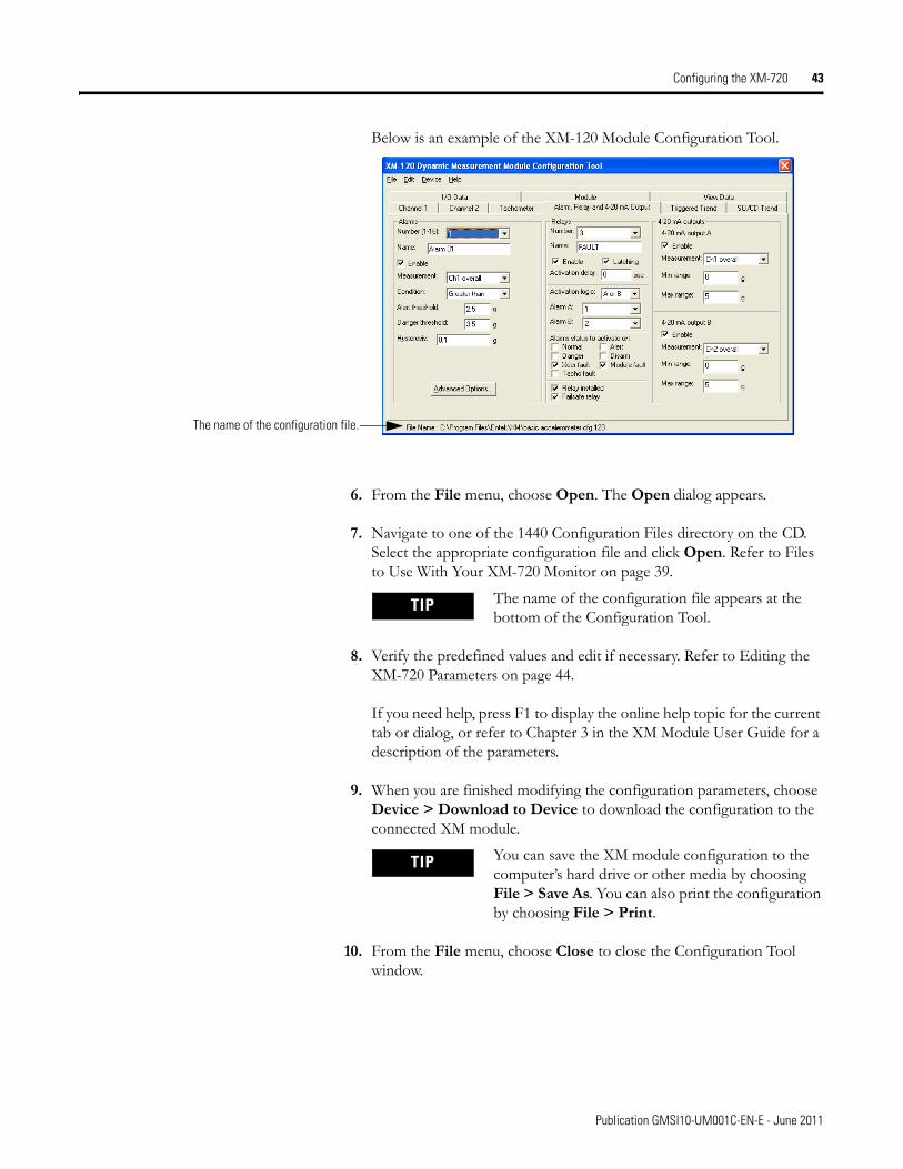
Below is an example of the XM-120 Module Configuration Tool.
6. From the File menu, choose Open. The Open dialog appears.
7. Navigate to one of the 1440 Configuration Files directory on the CD. Select the appropriate configuration file and click Open. Refer to Files to Use With Your XM-720 Monitor on page 39.
8. Verify the predefined values and edit if necessary. Refer to Editing the XM-720 Parameters on page 44.
If you need help, press F1 to display the online help topic for the current tab or dialog, or refer to Chapter 3 in the XM Module User Guide for a description of the parameters.
9. When you are finished modifying the configuration parameters, choose Device > Download to Device to download the configuration to the connected XM module.
10. From the File menu, choose Close to close the Configuration Tool window.
The name of the configuration file.
TIP The name of the configuration file appears at the bottom of the Configuration Tool.
TIP You can save the XM module configuration to the computer’s hard drive or other media by choosing File > Save As. You can also print the configuration by choosing File > Print.
Publication GMSI10-UM001C-EN-E - June 2011

44 Configuring the XM-720
Editing the XM-720 Parameters
Once you open one of the provided configuration files, you can modify the existing parameters so they better meet your requirements.
Transducer Parameters
The Channel tab in the Configuration Tool allows you to change the characteristics of the transducers you will be using with your XM-720 monitor as well as the signal processing performed on channel 1 or channel 2. There are two Channel tabs, one for each channel.
In the provided configuration files, both channels are configured identically. Refer to Files to Use With Your XM-720 Monitor on page 39 for a list of the provided configuration files.
To modify the channel parameters, follow these steps.
1. In the XM Module Configuration Tool, click the appropriate Channel tab. (Channel 1 is the default tab.) You will see a screen similar to this.
IMPORTANT Any configuration parameter changes that you make in the Configuration Tool do not affect the XM module until you download them to the module. To download the configuration parameters to the module, choose Device > Download to Device. The module begins using the new parameters immediately after the download.
Check this checkbox when anIEPE accelerometer is wired to
the channel. Uncheck thischeckbox when any other type
of transducer is wired to thechannel.
A voltage reading outside this range constitutes a transducer fault.
The XM-122 can only performgSE measurements with an
accelerometer. gSEmeasurements are only
available for this channel if youselect g.
Publication GMSI10-UM001C-EN-E - June 2011
Configuring the XM-720 45
2. Enter or select the desired parameters to configure the transducer sensitivity, operating range, and power requirements.
The signal processing and the measurement parameters affect the data units of the measurement values, the sampling mode of the spectrum/waveform data, and any spectral derived measurement.
3. When you are finished, choose Device > Download to Device to download your changes to the XM module.
gSE Parameters
Use the gSE tab in the XM-122 Configuration Tool to define the characteristics of the gSE signal processing performed on channel 1 and channel 2. The settings on the gSE tab are independent of the (conventional) Signal processing and Spectrum/Waveform settings on the Channel 1 and Channel 2 tabs.
In the provided configuration files, both channels are configured identically. Refer to Files to Use With Your XM-720 Monitor on page 39 for a list of the provided configuration files.
TIP Refer to Chapter 3 in the XM Module User Guide for a detailed description of the configuration parameters.
TIP Press F1 to display the online help topic for the current tab or dialog.
TIP The XM-122 can perform gSE measurements for a channel only with an accelerometer. The Eng. units must be set to "g" on the Channel 1 or Channel 2 tabs for gSE measurements.
Publication GMSI10-UM001C-EN-E - June 2011

46 Configuring the XM-720
To modify the gSE parameters, follow these steps.
1. In the XM-122 Configuration Tool, click the gSE tab. You will see a screen similar to this.
2. Enter or select the desired parameters to configure the gSE measurement.
3. When you are finished, choose Device > Download to Device to download your changes to the XM module.
Alarm Parameters
Use the Alarm, Relay and 4-20 mA Output tab in the Configuration Tool to select the type of measurement that is associated with an alarm and to set the alert and danger threshold values.
In the provided configuration files, alarm number 1 and 2 have been configured for you. Both alarms are configured identically except that Alarm Number 1 is set up to monitor Ch 1 overall and Alarm Number 2 is set up to
TIP Refer to Chapter 3 in the XM Module User Guide for a detailed description of the configuration parameters.
TIP Press F1 to display the online help topic for the current tab or dialog.
Publication GMSI10-UM001C-EN-E - June 2011

Configuring the XM-720 47
monitor Ch 2 overall. Refer to Files to Use With Your XM-720 Monitor on page 39 for list of the provided configuration files.
To modify the alarm parameters, follow these steps.
1. In the XM Configuration Tool, click the Alarm, Relay, and 4-20 mA tab. You will see a screen similar to this.
2. Select the Alarm Number that you want to modify or configure.
3. Enter or select the desired parameters to set up the behavior of the alarm. This includes:• the measurement that the alarm is monitoring• the measurement values at which the alarm changes state• the amount that the measurement must fall before the alarm
condition is cleared (hysteresis)• the action to take when the setpoint multiplier switch is closed
4. When you are finished, choose Device > Download to Device to download your changes to the XM module.
This checkbox must be checked inorder to use the alarm.
The measurement and channelassociated with the alarm.
The threshold values for thealert and danger threshold
conditions.
Determines on which side of the thresholdvalues the alert and danger conditions
exist.
Click to configure the Setpoint Multiplier switch.
TIP Refer to Chapter 3 in the XM Module User Guide for a detailed description of the configuration parameters.
TIP Press F1 to display the online help topic for the current tab or dialog.
Publication GMSI10-UM001C-EN-E - June 2011

48 Configuring the XM-720
Relay Parameters
Use the Alarm, Relay and 4-20 mA Output tab in the Configuration Tool to configure the behavior of the relays in the XM-720 monitor.
In the provided configuration files, the relays are configured to function as described in Table 3.4.
Refer to Files to Use With Your XM-720 Monitor on page 39 for a list of the provided configuration files.
Table 3.4 Pre-Configured Relay Functionality
IMPORTANT Making a change to the relay parameters may possibly change the intended function of the relay and front panel LED.
Configuration Tool Relay Number
Front Panel LED
Back Panel Connection Intended Function
1 Module Fault N/A Indicates a module fault, such as a hardware or firmware failure. Turns on the Module Fault LED on the front panel.
2 Xducer Fault N/A Indicates transducer DC bias on either channel is out-of-range. Turns on the Xducer Fault LED on the front panel.
3 N/A Fault Relay Indicates a module fault and/or transducer DC bias is out-of-range.
4 Warning Warning Relay
Indicates that the overall measurement in either channel exceeds either the alert level thresholds or the danger level thresholds.Turns on the Warning LED on the front panel.
5 Trip Trip Relay Indicates that the measurement in either channel exceeds the danger level thresholds. Turns on the Trip LED on the front panel.
Publication GMSI10-UM001C-EN-E - June 2011

Configuring the XM-720 49
To modify the relay parameters, follow these steps.
1. In the Configuration Tool, click the Alarm, Relay, and 4-20 mA tab. You will see a screen similar to this.
2. Select the relay Number that you want to modify or configure.
3. Enter or select the desired parameters to set up the behavior of the relay. This includes:• the number of seconds after an alarm condition has been exceeded
before the relay activates (activation delay)• the activation logic and the alarm(s) that the relay monitors• the conditions that will cause the relay to activate (for example,
module fault, measurement exceeds danger level thresholds)• whether the relay is latched and failsafe
4. When you are finished, choose Device > Download to Device to download your changes to the XM module.
Check the checkbox if the relay must be explicitlyreset. Uncheck the checkbox if the relay is to
reset itself once the alarm condition has passed.
The alarm conditions that cause the relay toactivate. More than one can be checked.
The relay activation logic and whatalarm(s) the relay is to monitor.
Check the checkbox if the relay is normallyenergized. Uncheck the checkbox if the relay is
normally de-energized.
The activation logic must persist for this length oftime before the relay is activated.
TIP Refer to Chapter 3 in the XM Module User Guide for a detailed description of the configuration parameters.
TIP Press F1 to display the online help topic for the current tab or dialog.
Publication GMSI10-UM001C-EN-E - June 2011
50 Configuring the XM-720
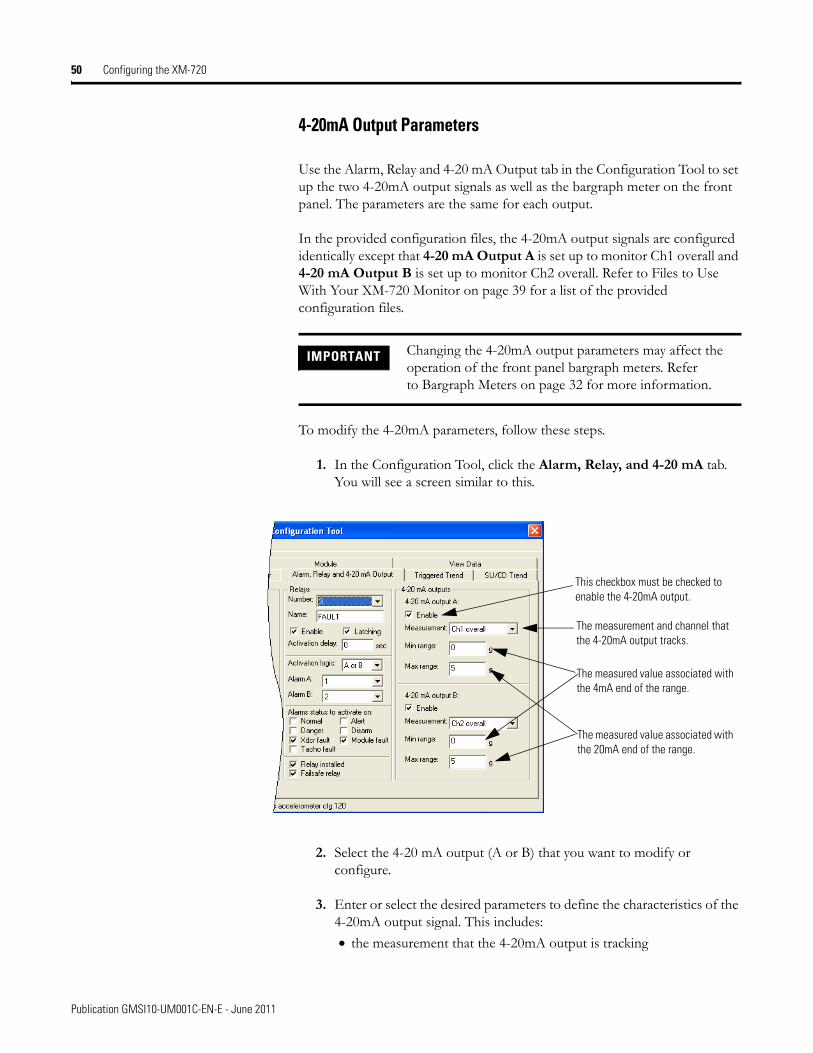
4-20mA Output Parameters
Use the Alarm, Relay and 4-20 mA Output tab in the Configuration Tool to set up the two 4-20mA output signals as well as the bargraph meter on the front panel. The parameters are the same for each output.
In the provided configuration files, the 4-20mA output signals are configured identically except that 4-20 mA Output A is set up to monitor Ch1 overall and 4-20 mA Output B is set up to monitor Ch2 overall. Refer to Files to Use With Your XM-720 Monitor on page 39 for a list of the provided configuration files.
To modify the 4-20mA parameters, follow these steps.
1. In the Configuration Tool, click the Alarm, Relay, and 4-20 mA tab. You will see a screen similar to this.
2. Select the 4-20 mA output (A or B) that you want to modify or configure.
3. Enter or select the desired parameters to define the characteristics of the 4-20mA output signal. This includes:• the measurement that the 4-20mA output is tracking
IMPORTANT Changing the 4-20mA output parameters may affect the operation of the front panel bargraph meters. Refer to Bargraph Meters on page 32 for more information.
This checkbox must be checked to enable the 4-20mA output.
The measurement and channel that the 4-20mA output tracks.
The measured value associated with the 4mA end of the range.
The measured value associated with the 20mA end of the range.
Publication GMSI10-UM001C-EN-E - June 2011

Configuring the XM-720 51
• the min and max range of the 4-20mA output signal
4. When you are finished, choose Device > Download to Device to download your changes to the XM module.
Tachometer Parameters
Use the Tachometer tab to enable the tachometer measurement and to define the characteristics of the tachometer as well as the signal processing that will be performed on the tachometer signal.
In the provided configuration files, the tachometer measurement has been disabled (Pulses per Revolution set to zero) to prevent a tachometer fault when no signal is present. Refer to Files to Use With Your XM-720 Monitor on page 39 for a list of the provided configuration files.
To modify the tachometer parameters, follow these steps.
1. In the Configuration Tool, click the Tachometer tab. You will see a screen similar to this.
TIP Refer to Chapter 3 in the XM Module User Guide for a detailed description of the configuration parameters.
TIP Press F1 to display the online help topic for the current tab or dialog.
A voltage readingoutside this range
constitutes atachometer fault.
To enable the tachometer measurement, enter a non-zero value.
Check this checkbox to enable Auto Trigger mode. Uncheck this to enable Manual Trigger mode and enter Trigger threshold and Trigger slope.
Publication GMSI10-UM001C-EN-E - June 2011
52 Configuring the XM-720
2. Enter or select the desired parameters to define the characteristics of the tachometer signal. This includes:• the minimum and maximum expected DC voltage• the DC bias time constant• the number of tachometer signal pulses per revolution of the shaft• the amount of hysteresis around the trigger threshold
3. When you are finished, choose Device > Download to Device to download your changes to the XM module.
TIP Refer to Chapter 3 in the XM Module User Guide for a detailed description of the configuration parameters.
TIP Press F1 to display the online help topic for the current tab or dialog.
Publication GMSI10-UM001C-EN-E - June 2011

Appendix A
Specifications
The Appendix lists the technical specifications for the XM-720 Machine Monitor.
XM-720 Technical Specifications
Product Feature Specification
CommunicationsLocal Configuration
DeviceNet
Local configuration is provided through the serial port connection of the XM-120/121/122 module. The serial port is accessed from the top or side of the XM-720 enclosure. NOTE: Required XM Serial Configuration Utility software and serial cable are packaged with the XM-720 Machine Monitor.
Remote system access is available through the integral DeviceNet connection of the XM-120/121/122. Consult the appropriate XM Module Users Guide (included) and the DeviceNet Cable System Planning and Installation Manual (www.odva.org) if implementing a network solution.
Inputs2 Signal Conditioning Channels
Tachometer
Eddy current transducer signalsAccelerometer signalsVoltage signals from any dynamic measurement device, such as a velocity or pressure transducer
±25V (50V max. peak to peak)1 to 50,000 events per revolution
Outputs4-20mA Outputs
Buffered Outputs
Two isolated outputs250 ohm max load
2 active buffers, one per channel1 resistive buffer for tachometertethered dust cover
Indicators4 Front Panel LEDs Module Fault
Transducer FaultWarning Trip
53 Publication GMSI10-UM001C-EN-E - June 2011

54 Specifications
Digital MetersNumber
LEDs
Size
Dimensions (HxW)
Scale
2Removable black bezel with white faceplate and black lettering
31 behind red tint filter
1/16 DIN
9.6 x 2.4 mm (3.8 x 0.95 in)
0 to 100%0, 25, 50, 75, 100% major divisions5% minor divisions
RelaysNumber
Relay Rating
3 SPDT (Module/Transducer/Tachometer Fault, Warning, and Trip)
250V ac @ 3 A resistive
Power Volts
Amps
Watts
100 to 240V ac
0.28 to 0.12A max.
28 max.
EnvironmentalOperating Temperature
Storage Temperature
Relative Humidity
-20 to +65°C (-4 to +149°F)
-40 to +85°C (-40 to +185°F)
95% non-condensing
PhysicalDimensions, Cutout (HxWxD)
Dimensions, Faceplate (HxW)
18.42 x 13.82 x 30.45 mm (7.25 x 5.44 x 11.99 in)
22.23 x 14.36 cm (8.75 x 5.66 in)
EnclosureNorth America
NEMA/CSA/UL
Europe
NEMA Type 1 panel mounting construction, for indoor use
IP 20
XM-720 Technical Specifications
Product Feature Specification
Publication GMSI10-UM001C-EN-E - June 2011

Specifications 55
Approvals(when product or packaging is marked)
*See the Product Certification link at www.rockwellautomation.com for Declarations of Conformity, Certificates and other certification details.
XM-720 Technical Specifications
Product Feature Specification
CSA CSA Certified Process Control Equipment
CSA CSA Certified Process Control Equipment for Class I, Division 2 Group A, B, C, and D Hazardous Locations
CE* European Union 89/336/EEC EMC Directive
C-Tick* Australian Radiocommunications Act, compliant with:AS/NZS 2064, Industrial Emissions
Publication GMSI10-UM001C-EN-E - June 2011

56 Specifications
Publication GMSI10-UM001C-EN-E - June 2011

Appendix B
Comparing Connections Between the 5802 and the XM-720
This appendix compares the connections between the 5802 monitor to those of the XM-720 Machine Monitor.
Power Supply & Relay Connections
Table B.1 defines the power supply, alarm relay and control connectors for the 5802, and the comparable connectors on the XM-720.
Table A.1 Power Supply & Relay Connections
5802 XM-720
Power Supply & Relay
Description TB1 Description
1 Line (Black) L AC Input Line
2, 3, 4, or 5 Neutral N AC Input Neutral
Chassis ground lug Ground E AC Earth Ground
6 Close on Trip Alarm 10 Trip Relay NO
7 Trip Alarm Common 11 Trip Relay Common
8 Open on Trip Alarm 12 Trip Relay NC
9 Close on Warning Alarm 7 Warning Relay NO
10 Warning Alarm Common 8 Warning Relay Common
11 Open on Warning Alarm 9 Warning Relay NC
12 Open on Fault Alarm 4 Fault Relay NO
13 Fault Alarm Common 5 Fault Relay Common
14 Close on Fault Alarm 6 Fault Relay NC
15 Remote Reset Momentary Switch 13 Reset Relay Switch
16 Return for Remote Reset and Setpoint Multiplier Switch
14 Switch RTN
57 Publication GMSI10-UM001C-EN-E - June 2011

58 Comparing Connections Between the 5802 and the XM-720
Signal Conditioner Connections
Table B3 defines the different types of signal conditioning connectors for 5802, and the comparable connectors on the XM-720.
Table A.2 Signal Conditioner Connections
5802 Wiring Signal XM-720 Wiring
Signal Conditioner Terminal Strips
403/2100 544M 911S/941/9100 910M/960/960M TB 2 Description
T/S1
5 4 1 2 Signal A 17 Xducer 1 (+)
4 3 3 3 Common A 18 Xducer 1 (-)
----- 7 7 7 Shield A 19 Chassis GND
----- ----- ----- 2 +24 V 23 Xducer +24 V
9 ----- ----- ------ -24 V 24 Xducer -24 V
8 8 8 8 4-20mA Chan A + 25 4-20mA 1 (+)
3 3 3 3 4-20mA Chan A return 26 4-20mA 1 (-)
T/S2
6 7 10 9 Signal B 20 Xducer 2 (+)
8 8 8 8 Common B 21 Xducer 2 (-)
----- 4 ----- 5 Shield B 22 Chassis GND
----- ------ ----- ----- +24 V 23 Xducer +24 V
----- ------ ----- ----- -24 V 24 Xducer -24 V
3 3 3 3 4-20mA Chan B + 28 4-20mA 2 (+)
8 8 8 8 4-20mA Chan B return 29 4-20mA 2 (-)
Publication GMSI10-UM001C-EN-E - June 2011

Glossary
alarm
An alarm alerts you to a change in a measurement. For example, an alarm can notify you when the measured vibration level for a machine exceeds a pre-defined value.
band
A frequency range, such as the frequency range between 1,800 and 3,200Hz.
bus off
A bus off condition occurs when an abnormal rate of errors is detected on the Control Area Network (CAN) bus in a device. The bus-off device cannot receive or transmit messages on the network. This condition is often caused by corruption of the network data signals due to noise or baud rate mismatch.
current configuration
The current configuration is the most recently loaded set of configuration parameters in the XM module’s memory. When power is cycled, the current configuration is loaded with either the saved configuration (in EEPROM) or the factory defaults (if there is no saved configuration). In addition, the current configuration contains any configuration changes that have been downloaded to the module since power was applied.
disarm state
See Program mode.
EEPROM
See NVS (Non-Volatile Storage).
Electronic Data Sheet (EDS) Files
EDS files are simple text files that are used by network configuration tools such as RSNetWorx for DeviceNet to describe products so that you can easily commission them on a network. EDS files describe a product device type, revision, and configurable parameters.
failsafe
Failsafe means that when in alarm, the relay contacts are in their "normal," de-energized, or "shelf-state" positions. In other words, normally closed relays are closed in alarm, and normally open relays are open in alarm. With failsafe operation, a power failure equals an alarm.
59 Publication GMSI10-UM001C-EN-E - June 2011

Glossary 60
For failsafe operation, the following are true:
• Under nonalarm (with power applied to the unit) conditions, the relay closes the circuit between the common and the N.O. terminals
• Under alarm or loss-of-power conditions, the relay changes state to close the circuit between the common and the N.C. terminals.
gSE measurement
A special type of signal processing. gSE, or Spike Energy, is useful for detecting low amplitude, high frequency signals characteristic of bearing and gearbox defects.
gSE spectrum
A special type of spectrum measurement using gSE signal processing. gSE, or Spike Energy, is useful for detecting low amplitude, high frequency signals characteristic of bearing and gearbox defects.
Help window
A window that contains help topics that describe the operation of a program. These topics may include:
• An explanation of a command.• A description of the controls in a dialog box or property page.• Instructions for a task.• Definition of a term.
high pass filter
A filter that excludes all frequencies below a defined frequency. It allows, or passes, frequencies above the defined frequency. It is useful for removing low frequency signal components that would dominate the signal.
low pass filter
A low pass filter excludes frequencies above a defined frequency. It allows, or passes, frequencies below the defined frequency. It is useful as an anti-aliasing filter.
non-failsafe
Non-failsafe means that when in non-alarm, the relay contacts are in their "normal," de-energized, or "shelf-state" positions. In other words, the relay is normally not energized and energizes (pulls in) upon alarm condition.
Publication GMSI10-UM001C-EN-E - June 2011

Glossary 61
For non-failsafe operation, the following are true:
• Under nonalarm conditions, the relay closes the circuit between the common and the N.C. (normally closed) terminals.
• Under alarm conditions, the relay changes state to close the circuit between the common and the N.O. (normally open) terminals.
NVS (Non-Volatile Storage)
NVS is the permanent memory of an XM module. Modules store parameters and other information in NVS so that they are not lost when the module loses power (unless Auto Save is disabled). NVS is sometimes called “EEPROM.”
online help
Online help allows you to get help for your program on the computer screen by pressing F1. The help that appears in the Help window is context sensitive, which means that the help is related to what you are currently doing in the program.
orders
Multiples of the operating speed of a piece of equipment. The first order is the operating speed. The second order is two times the operating speed, and so on.
Program mode
The XM module is idle. Typically this occurs when the module configuration settings are being updated with the XM Configuration program. In Program mode, the signal processing/measurement process is stopped. The status of the alarms is set to the disarm state to prevent a false alert or danger status.
Run mode
In Run mode, the module collects measurement data and monitors each measurement device.
settling time
The amount of time it takes a measurement to reach 90% of the final value given a step change in the input signal.
signal detection
Defines the method of conditioning or measuring a dynamic input signal. Peak (0 to the peak voltage), Peak-Peak (minimum peak to maximum peak), and RMS (square root of the mean of the square of the values) are the most common methods of signal detection.
Publication GMSI10-UM001C-EN-E - June 2011

Glossary 62
startup/coast-down trend
A speed-base trend that is collected in an XM module during the startup or coast-down of a machine when the measured machine speed crosses into a defined speed range.
transducer
A transducer is a device for making measurements. These include accelerometers, velocity pickups, displacement probes, and temperature sensors.
virtual relay
A virtual relay is a non-physical relay. It has the same capabilities (monitor alarms, activation delay, change status) as a physical relay only without any physical or electrical output. The virtual relay provides additional relay status inputs to a controller or PLC.
XM configuration
XM configuration is a collection of user-defined parameters for XM modules.
XM Serial Configuration Utility software
XM Serial Configuration Utility software is a tool for monitoring and configur-ing XM modules. It can be run on computers running Windows 2000 service pack 2, Windows NT 4.0 service pack 6, or Windows XP operating systems.
Publication GMSI10-UM001C-EN-E - June 2011

Index
Symbols.120 39.121 39, 40.122 39, 41
Numerics1440PK0205M0 configuration files 391440PK0205M1 configuration files 401440PK0205M2 configuration files 414-20mA output parameters 504-20mA outputs
configuring 50wiring 29
Aabout XM Serial Configuration Utility 37alarm parameters 46Alarm, Relay and 4-20 mA Output tab 46, 48, 50alarms, configuring 46
Bbargraph meters 32
customizing 32determine signal amplitude 33determine threshold levels 33
BNC connectors 34buffered outputs, configuring 20
CChannel tab 44configuration files 39
1440PK0205M0 (XM-120) 391440PK0205M1 (XM-121) 401440PK0205M2 (XM-122) 41description 39download to XM module 41editing 44
configuring4-20mA outputs 50alarms 46gSE 45relays 48tachometer 51transducers 44
connecting wiring 134-20mA outputs 29back panel 13power supply 16relays 16
fault relay 17trip relay 18warning relay 17
remote relay reset signal 19setpoint multiplication switch 30tachometer 28terminal blocks 14transducers 19
Ddocument conventions 7downloading configuration files 41
Eediting configuration files 44
FFault relay 17file extensions
.120 39
.121 40
.122 41front panel 31
GgSE parameters 45gSE tab 45
Hhazardous locations 11
Iinstallation guidelines 10
hazardous locations 11selecting location 10wiring 11
installing XM Serial Configuration Utility 37introduction 5
Publication GMSI10-UM001C-EN-E - June 2011
64 Index
LLEDs 34
Module Fault 35Trip 34Warning 34Xdcr Fault 35
Mmounting 13
cutout dimensions 12mounting dimensions 11
NNormally Closed relay contacts 16Normally Open relay contacts 16
Ppackage contents 10
Rrelay contacts
normally closed 16normally open 16
relay functionality, description 48relay parameters 48relays
configuring 48fault relay 17resetting 35trip relay 18warning relay 17
remote relay reset signal, wiring 19removable terminal blocks 35
inserting 36removing 36wiring 13
Reset button 35
Sselecting a location for XM-720 10
serial cable 10, 37, 42setpoint multiplication switch, wiring 30specifications 53spring clamp connectors 14system description 6
Ttachometer
configuring 51tachometer parameters 51Tachometer tab 51tachometer, wiring 28terminal block assignment 14transducer parameters 44transducer wiring
setting buffer range 20transducers
configuring 44wiring 19
IEPE accelerometer 22non-contact sensor 23passive transducer 25powered sensor 26
Trip relay 18troubleshooting 34
WWarning relay 17wiring comparison between 5802 & XM-720
power supply & relay connections 57signal conditioner connections 58
wiring connections4-20mA outputs 29power supply 16relays 16
fault relay 17trip relay 18warning relay 17
remote relay reset signal 19setpoint multiplication switch 30tachometer 28transducers 19
Publication GMSI10-UM001C-EN-E - June 2011

Index 65
XXM cable connection 38XM Serial Configuration Utility
about 37installing 37
XM-120 configuration files 39XM-121 configuration files 40XM-122 configuration files 41XM-720 Machine Monitor
bargraph meters 32BNC connectors 34catalog numbers 5, 10components 5
configuration files 39configuring 37cutout dimensions 12front panel 31installation guidelines 10introduction 5LEDs 34mounting 13mounting dimensions 11package contents 10reset button 35specifications 53system description 6
Publication GMSI10-UM001C-EN-E - June 2011

66 Index
Publication GMSI10-UM001C-EN-E - June 2011


Rockwell Otomasyon Ticaret A.Ş., Kar Plaza İş Merkezi E Blok Kat:6 34752 İçerenköy, İstanbul, Tel: +90 (216) 5698400
Publication GMSI10-UM001C-EN-E - June 2011 67Supersedes Publication GMSI10-UM001B-EN-E - April 2006 Copyright © 2011 Rockwell Automation, Inc. All rights reserved. Printed in the U.S.A.
Rockwell Automation Support
Rockwell Automation provides technical information on the Web to assist you in using its products. At http://www.rockwellautomation.com/support/, you can find technical manuals, a knowledge base of FAQs, technical and application notes, sample code and links to software service packs, and a MySupport feature that you can customize to make thebest use of these tools.
For an additional level of technical phone support for installation, configuration, and troubleshooting, we offer TechConnect support programs. For more information, contact your local distributor or Rockwell Automation representative, or visit http://www.rockwellautomation.com/support/.
Installation Assistance
If you experience a problem within the first 24 hours of installation, review the information that is contained in this manual.You can contact Customer Support for initial help in getting your product up and running.
New Product Satisfaction Return
Rockwell Automation tests all of its products to ensure that they are fully operational when shipped from the manufacturing facility. However, if your product is not functioning and needs to be returned, follow these procedures.
Documentation Feedback
Your comments will help us serve your documentation needs better. If you have any suggestions on how to improve this document, complete this form, publication RA-DU002, available at http://www.rockwellautomation.com/literature/.
United States or Canada 1.440.646.3434
Outside United States or Canada
Use the Worldwide Locator at http://www.rockwellautomation.com/support/americas/phone_en.html, or contact your local Rockwell Automation representative.
United States Contact your distributor. You must provide a Customer Support case number (call the phone number above to obtain one) to your distributor to complete the return process.
Outside United States Please contact your local Rockwell Automation representative for the return procedure.