Embed Size (px)
Citation preview
Designing and Prototyping
Networked Collaborative Play Structures
by
Kristin Michelle Zimmerman
Submitted to the
Department of Mechanical Engineering
in Partial Fulfillment of the Requirements for the Degree of
ARCHNESMASSACHUSETTS INSTITI ITE
OF TECHNOLOLGY
JUN 242015
LIBRARIES
Bachelor of Science in Mechanical Engineering
at the
Massachusetts Institute of Technology
June 2015
@ 2015 Kristin Michelle Zimmerman. All rights reserved.
The author hereby grants to MIT permission to reproduce and to distribute publicly paper and electroniccopies of this thesis document in whole or in part in any medium now known or hereafter created.
Signature of
Certified by:
Accepted by:
Author:Si
77-
gnature redactedDepartment of M hanical Engineering
/1 May 11, 2015
Signature redacted* r V. Michael Bove Jr.
Principal Research Scientist
Thesis Supervisor
Signature redactedAnette Hosoi
Professor of Mechanical Engineering
Undergraduate Officer
Designing and Prototyping
Networked Collaborative Play Structuresby
Kristin Michelle Zimmerman
Submitted to the Department of Mechanical Engineering on May 11, 2015 in Partial Fulfillment of the
Requirements for the Degree of Bachelor of Science in Mechanical Engineering
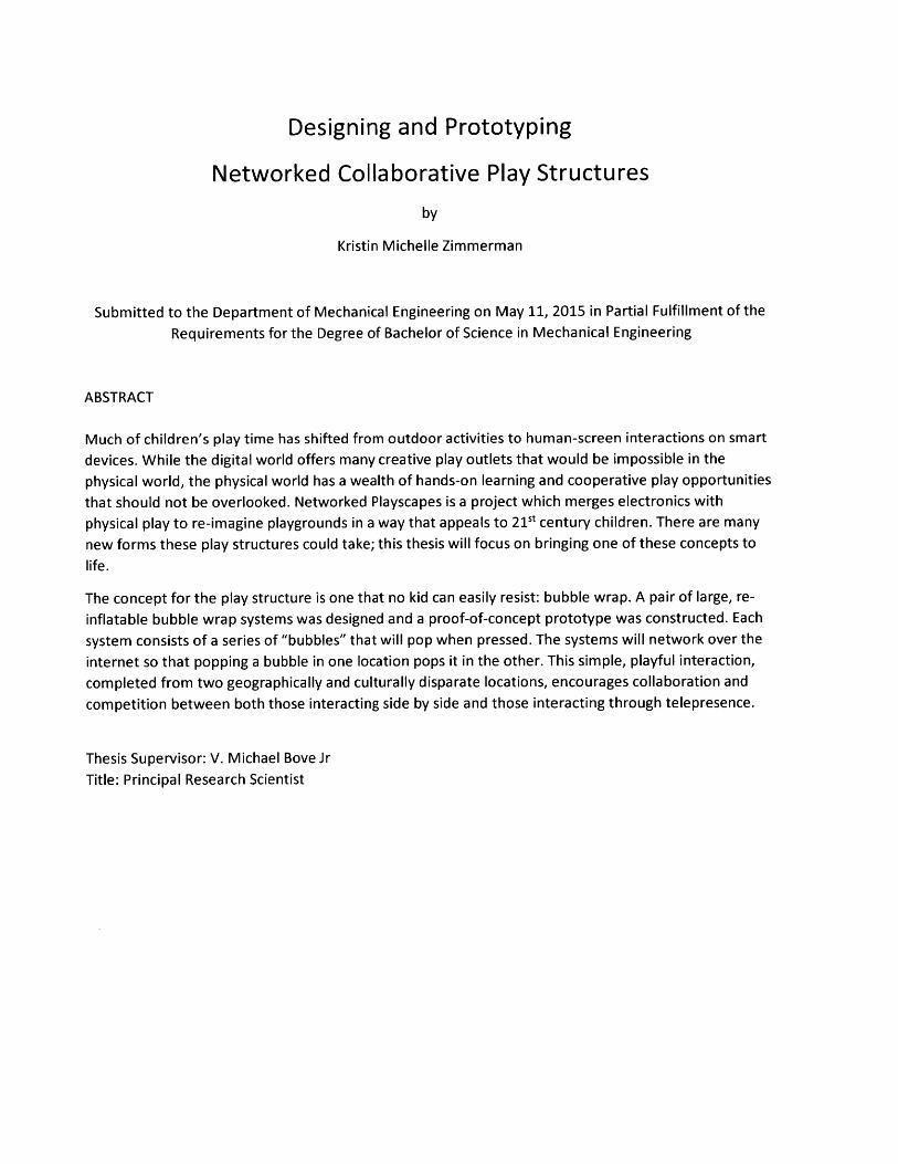
ABSTRACT
Much of children's play time has shifted from outdoor activities to human-screen interactions on smart
devices. While the digital world offers many creative play outlets that would be impossible in the
physical world, the physical world has a wealth of hands-on learning and cooperative play opportunities
that should not be overlooked. Networked Playscapes is a project which merges electronics with
physical play to re-imagine playgrounds in a way that appeals to 21t century children. There are many
new forms these play structures could take; this thesis will focus on bringing one of these concepts to
life.
The concept for the play structure is one that no kid can easily resist: bubble wrap. A pair of large, re-
inflatable bubble wrap systems was designed and a proof-of-concept prototype was constructed. Each
system consists of a series of "bubbles" that will pop when pressed. The systems will network over the
internet so that popping a bubble in one location pops it in the other. This simple, playful interaction,
completed from two geographically and culturally disparate locations, encourages collaboration and
competition between both those interacting side by side and those interacting through telepresence.
Thesis Supervisor: V. Michael Bove Jr
Title: Principal Research Scientist
ACKNOWLEDGEMENTS
Many thanks to all of the people who helped me along this fantastic journey. Thank you, Edwina;
without your Networked Playscapes thesis and your encouragement along the way this project would
not have been possible. Thank you, Dr. Bove, for all that you have taught me, including the value of
hacking quick prototypes and test pieces. Thank you to the wonderful members of the Object Based
Media Group who were always quick to answer my questions and help me locate stuff around the lab.
Thank you also to all of my dormmates who put up with me building stuff in the lounge over many
weekends and were always happy to act as sounding boards for my zany ideas.
TABLE OF CONTENTS
I In tro d u ctio n .......................................................................................................................................... 7
1.1 The Role of Playgrounds ............................................................................................................... 7
1.2 Networked Playscapes .................................................................................................................. 7
2 Selecting a Com pelling Interaction ....................................................................................................... 9
2.1 Types of Interactions ..................................................................................................................... 9
2.1.1 Presence-Based ..................................................................................................................... 9
2.1.2 Collaboration ....................................................................................................................... 10
2.1.3 Co-Creation ......................................................................................................................... 12
2.1.4 Com petition ........................................................................................................................ 13
2.2 Concept Selection ....................................................................................................................... 14
3 Design Iterations ................................................................................................................................. 16
3.1 The Bubbles ................................................................................................................................. 17
3.1.1 M aterials ............................................................................................................................. 17
3.1.2 Fabrication M ethods ........................................................................................................... 18
3.1.3 Shapes ................................................................................................................................. 19
3.2 Inflation and Deflation ................................................................................................................ 19
3.2.1 Fan Grid Concept ................................................................................................................. 19
3.2.2 Popping Cork Concept ......................................................................................................... 21
3.2.3 Solenoid and Check Valve Concept ..................................................................................... 22
3 .3 S e n sin g ........................................................................................................................................ 2 3
3.3.1 Pressure Transducers .......................................................................................................... 23
3.3.2 Two-Balloon Concept .......................................................................................................... 24
4 Proof of Concept Prototype ................................................................................................................ 25
4.1 The Bubbles ................................................................................................................................. 25
4.2 Pneumatics .................................................................................................................................. 28
4.2.1 Inflation ............................................................................................................................... 29
4.2.2 Deflation .............................................................................................................................. 30
4.3 Electronics ................................................................................................................................... 32
4 .3 .1 S e n sin g ................................................................................................................................ 3 2
4.3.2 Solenoid Control .................................................................................................................. 33
4.4 Assem bly ..................................................................................................................................... 34

5 Plans for the Final Build ................................................................................ .......... .--------............. 36
5.1 System Refinem ents .........................................................................................................----... 36
5.2 Dem onstration System ............................................................................................... . ........... 37
5.3 Networked System ....................................................................................................... ........... 39
6 Conclusion...................................................................................................................... .. ........... 40
7 Bibliography .................................................................................................. ........ ---------------......... 42
TABLE OF FIGURES
Figure 1: Snow Globe Concept....................................................................................................................10
Figure 2: Forest of Colors .............................................................................................. ....................----- 11
Figure 3: Co-Creation Building Blocks ..................................................................................................... 12
Figure 4: Bubble W rap Concept .................................................................................................................- 14
Figure 5: Bubble Form s Explored................................................................................................................19
Figure 6: Fan-Inflated Bubble...................................................................................................... ............. 20
Figure 7: Popping Cork Concept..................................................................................................................21
Figure 8: Solenoid and Check Valve Concept.......................................................................................... 22
Figure 9: Break Beam Illustration................................................................................................................24
Figure 10: Successful Bubble Fabrication. ............................................................................................... 26
Figure 11: Bubble Backing........................................................................................................................... 27
Figure 12: W eight to Aid Deflation. ............................................................................................................ 28
Figure 13: Inflation System Diagram ........................................................................................................... 29
Figure 14: Testing for Leaks ........................................................................................................................ 30
Figure 15: Deflation System Diagram ......................................................................................................... 30
Figure 16: %" NPT Solenoid......................................................................................................................... 31
Figure 17: Break Beam Schem atic............................................................................................................... 32
Figure 18: Pressure Sensor Photo .......................................................................................................--. 33
Figure 19: Solenoid Circuit Diagram ....................................................................................................... 34
Figure 20: Rear View of Proof of Concept Prototype. ................................................................................ 34
Figure 21: Popping the Test Bubble ............................................................................................................ 35
Figure 22: Sensor Cap ................................................................................................................................ 36
Figure 23: Dem onstration System .............................................................................................................. 38
Figure 24: Electronics Assem bly on Final Structure ................................................................................. 39
Figure 25: Networking................................................................................................................. ...--------- 40

TABLE OF TABLES
Table 1: Interaction Selection Pugh Chart ............................................................................................. 15
Table 2: M aterial Selection Pugh Chart .................................................................................................. 17
Table 3: Fabrication Methods for Fabrics, Plastics, and Foils ................................................................ 18
1 INTRODUCTION
1.1 THE ROLE OF PLAYGROUNDS
Playgrounds are meant to offer a unique space for children to experiment, explore, develop their social
skills, work their muscles, and take risks in a controlled environment. Despite their import, these spaces
for physical play have largely stagnated over the past half century. Playgrounds as a whole have not
risen to meet the new challenges and opportunities of new generations of children seeking play. On
most playgrounds one can see the same jungle gyms, monkey bars, and swings that were there thirty
years ago; the materials these structures are made out of may have been updated, but the interactions
remain unchanged. Playgrounds are generally only aimed at younger children, with teens and adults
largely left out of the equation. The spaces generally look identical whether in California, the Midwest,
or New England. There is a growing movement of innovators who want to revitalize playgrounds and
attract new audiences. Networked Playscapes is one such movement.
1.2 NETWORKED PLAYSCAPES
Networked Playscapes is a new approach to playground design which merges electronics with physical
play to re-imagine playgrounds in a way that appeals to 2 1st century children and crosses generational
boundaries. Much of children's play time has shifted from outdoor activities to human-screen
interactions on smart devices. While the digital world offers many creative play outlets that would be
impossible in the physical world, the physical world has a wealth of hands-on learning and cooperative
play opportunities that should not be overlooked.
Bringing electronics into the world of playgrounds introduces a wealth of new possibilities for
interaction. This project aims to explore networked playgrounds. People around the world are more
interconnected than ever with the advent of social networking. These interactions, when occurring
7
across large distances, are mostly limited to bits and pixels. Combining networking with playscapes gives
a unique opportunity for people to tangibly interact across vast distances. There is something visceral
about physical interactions that purely digital interactions are hard pressed to imitate. Networked
playscapes would allow people of different cultures to interact with each other in a way that was never
before possible. Children from neighborhoods divided by issues of race and class could be given a
chance to interact with each other through these structures.
As Networked Playscapes is an attempt at formulating a new design language for playgrounds, the
playscape I will build is most useful when framed in the context of other networked playscapes. The
Networked Playscapes concept is in its relative infancy; example playscapes are being built and tested to
refine the concept and see how this new playground design language fits into playground design as a
whole. There are two formal networked playscapes that precede mine: ListenTree (Dublon &
Portocarrero, 2014) and Dig Deep (Portocarrero, To be published in 2016). ListenTree is an audio-haptic
display that is embedded in the natural environment. When one presses their ear against a networked
tree they can hear sounds- music, stories, recorded sounds, etc. - through bone conduction. Dig Deep
brings the old children's tale of digging to the other side of the world to life. A live feed looking up from
the bottom of a networked sandbox is played on a screen under the sand. If people are digging in both
sandboxes at the same time they can see each other through the hole in the sand. The visual feed is
accompanied by audio; the sound of someone digging from the other side can be heard at a distance,
enticing people to come over and interact.
Since audio and visual telepresence were explored in the previous Networked Playscapes projects
I wanted to focus my attention elsewhere; there is more to be learned about these playscapes from an
example that explores a new area of possible interactions. The interaction that I ultimately chose is
primarily tactile and introduces an element of competitive play that the other projects eschew. I will
8
prototype giant, networked, re-poppable bubble wrap. I will discuss choosing the interaction, designing
the system, mocking up a proof of concept, and building the system in the following sections.
2 SELECTING A COMPELLING INTERACTION
When designing a play structure, the play experience is of primary importance. The build should stem
from a compelling interaction, not the other way around. The interaction of people with the structure
and of people with each other are both important to consider. I will present the types of interactions I
found most compelling, give an example for each, and then describe how I came to the decision to
pursue the giant, re-poppable bubble wrap concept.
2.1 TYPES OF INTERACTIONS
"Networked Playscapes" is a broad category that encapsulates a multitude of possible interactions.
More so than a particular interaction, it is a new approach to thinking about playground design. Since
the thinking space is so large, I found it useful divide the space for the purposes of figuring out what
form I wanted this new playscape to take. The following sections illuminate the subdivisions of the
umbrella that spawned many interesting concepts during the ideation stage of this project.
2.1.1 Presence-Based
These are interactions in which the presence of someone using one structure in the networked pair is
somehow alluded to in the other. This ghosted telepresence can be visual, aural, tactile, olfactory, or a
combination of these. The presence could be more literal, like a video chat, or much more abstracted,
like the pulsing of light with a faraway heartbeat. This type of interaction is based upon people being
able to perceive each other's presence in a way that gives them the sense that they are in the same
space. Thus, the interaction itself can be left very open-ended; if two people are in the same room they
may play tag, ignore each other, snuggle, start a conversation, dance, or do any number of other things.
9
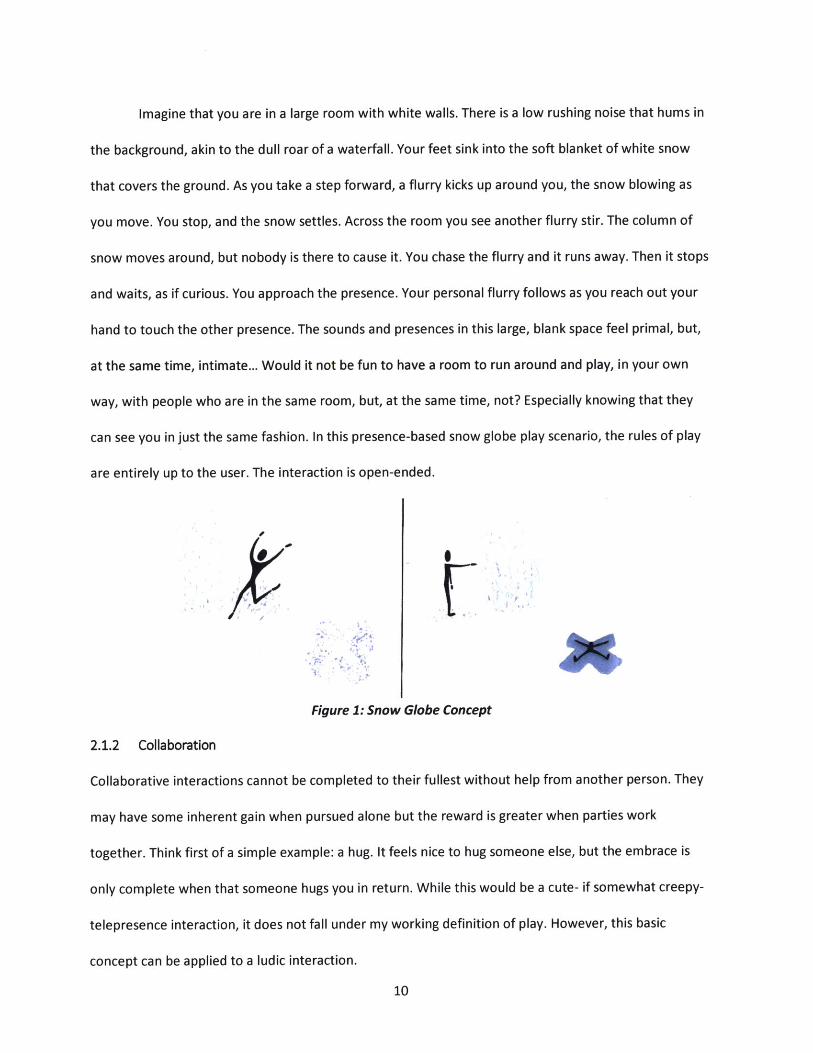
Imagine that you are in a large room with white walls. There is a low rushing noise that hums in
the background, akin to the dull roar of a waterfall. Your feet sink into the soft blanket of white snow
that covers the ground. As you take a step forward, a flurry kicks up around you, the snow blowing as
you move. You stop, and the snow settles. Across the room you see another flurry stir. The column of
snow moves around, but nobody is there to cause it. You chase the flurry and it runs away. Then it stops
and waits, as if curious. You approach the presence. Your personal flurry follows as you reach out your
hand to touch the other presence. The sounds and presences in this large, blank space feel primal, but,
at the same time, intimate... Would it not be fun to have a room to run around and play, in your own
way, with people who are in the same room, but, at the same time, not? Especially knowing that they
can see you in just the same fashion. In this presence-based snow globe play scenario, the rules of play
are entirely up to the user. The interaction is open-ended.
Figure 1: Snow Globe Concept
2.1.2 Collaboration
Collaborative interactions cannot be completed to their fullest without help from another person. They
may have some inherent gain when pursued alone but the reward is greater when parties work
together. Think first of a simple example: a hug. It feels nice to hug someone else, but the embrace is
only complete when that someone hugs you in return. While this would be a cute- if somewhat creepy-
telepresence interaction, it does not fall under my working definition of play. However, this basic
concept can be applied to a ludic interaction.
10
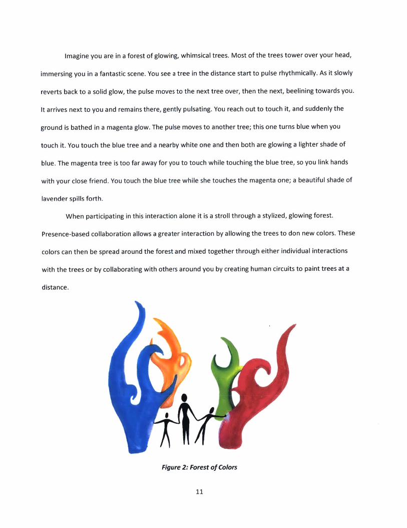
Imagine you are in a forest of glowing, whimsical trees. Most of the trees tower over your head,
immersing you in a fantastic scene. You see a tree in the distance start to pulse rhythmically. As it slowly
reverts back to a solid glow, the pulse moves to the next tree over, then the next, beelining towards you.
It arrives next to you and remains there, gently pulsating. You reach out to touch it, and suddenly the
ground is bathed in a magenta glow. The pulse moves to another tree; this one turns blue when you
touch it. You touch the blue tree and a nearby white one and then both are glowing a lighter shade of
blue. The magenta tree is too far away for you to touch while touching the blue tree, so you link hands
with your close friend. You touch the blue tree while she touches the magenta one; a beautiful shade of
lavender spills forth.
When participating in this interaction alone it is a stroll through a stylized, glowing forest.
Presence-based collaboration allows a greater interaction by allowing the trees to don new colors. These
colors can then be spread around the forest and mixed together through either individual interactions
with the trees or by collaborating with others around you by creating human circuits to paint trees at a
distance.
Figure 2: Forest of Colors
11
2.1.3 Co-Creation
The difference between collaboration and co-creation is subtle and is admittedly somewhat like the
rectangle-square relationship. Collaboration can exist without co-creation, but collaboration is inherent
to co-creation. I have separated it into its own category because there are so many interactions to
explore that are distinctly creation-based. Really interesting things can happen when you give a group of
kids shovels and buckets at the beach; suddenly they become architects, knights, and princesses, co-
creating an imagined world through both the building of physical structures and the creation of stories
to map upon them. Of particular interest to me is co-creation across cultures. What do you get when
you give the same bucket and shovel to kids raised on bedtime stories about gods and monsters rather
than knights and princesses? Now imagine we allowed these two groups of kids to build something
together. What would we get? How would the stories each kids maps onto the structure change?
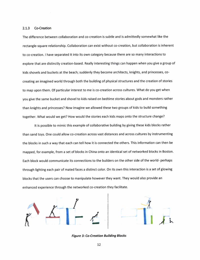
It is possible to mimic this example of collaborative building by giving these kids blocks rather
than sand toys. One could allow co-creation across vast distances and across cultures by instrumenting
the blocks in such a way that each can tell how it is connected the others. This information can then be
mapped, for example, from a set of blocks in China onto an identical set of networked blocks in Boston.
Each block would communicate its connections to the builders on the other side of the world- perhaps
through lighting each pair of mated faces a distinct color. On its own this interaction is a set of glowing
blocks that the users can choose to manipulate however they want. They would also provide an
enhanced experience through the networked co-creation they facilitate.
Figure 3: Co-Creation Building Blocks
12
2.1.4 Competition
Carnies make a living off of people who pay money to compete against each other, the host, or a skills
game. The prizes are often of trivial value, yet people are drawn to these interactions. Why? Many
people feel a natural desire to compete. To prove that they are better at something, to impress a girl, to
hold a bet over a friend's head, to let loose and do something silly- there are many reasons people
compete. A bit of healthy competition can make for a very engaging interaction that has people coming
back time and again to try to win against someone they previously lost to or against a new challenger.
When this notion of competition is paired with an interaction that is already fun on its own,
something compelling is likely to come of it. Take, for instance, bubble wrap. The stuff that everyone
secretly cannot help but pop every time a package comes in the mail. The feel, the sound, and the small
scale destruction they are able to wreak on each bubble make this an interaction that kids and adults
alike indulge in. People have been known to buy large rolls as a form of stress relief for college students
or as an activity at young kids' birthday parties. Google "bubble wrap" and you will even find animals
popping away at the stuff. Now add in an element of competition- there are a limited number of
bubbles and someone else has started to pop them alongside you. You pick up the pace before your
friend can pop more bubbles than you. Now picture this interaction, but networked. Now in addition to
the person standing right beside you popping bubbles, an unseen person is popping them from halfway
around the world. Now you have really got to pick up the pace- you cannot see where they will strike
next. This interaction is especially interesting because, when observing multiple people interacting over
standard bubble wrap, the interactions are not limited to competition. You may compete against the
other poppers, or you may decide to instead collaborate with them to pop all of the bubbles more
quickly, or you may choose to share, sticking to your own corner of the bubble wrap and only
approaching each other once the rest of the bubbles are popped. Best of all, this is an interaction that
13
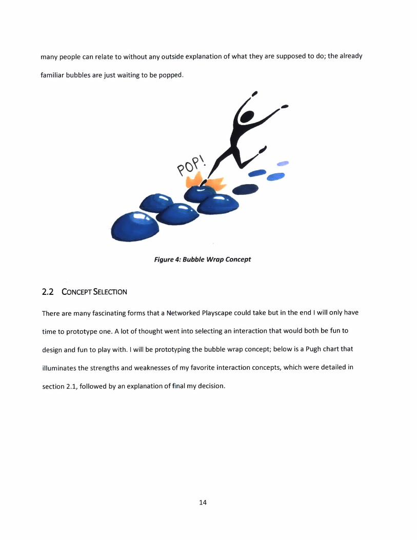
many people can relate to without any outside explanation of what they are supposed to do; the already
familiar bubbles are just waiting to be popped.
Figure 4: Bubble Wrap Concept
2.2 CONCEPT SELECTION
There are many fascinating forms that a Networked Playscape could take but in the end I will only have
time to prototype one. A lot of thought went into selecting an interaction that would both be fun to
design and fun to play with. I will be prototyping the bubble wrap concept; below is a Pugh chart that
illuminates the strengths and weaknesses of my favorite interaction concepts, which were detailed in
section 2.1, followed by an explanation of final my decision.
14
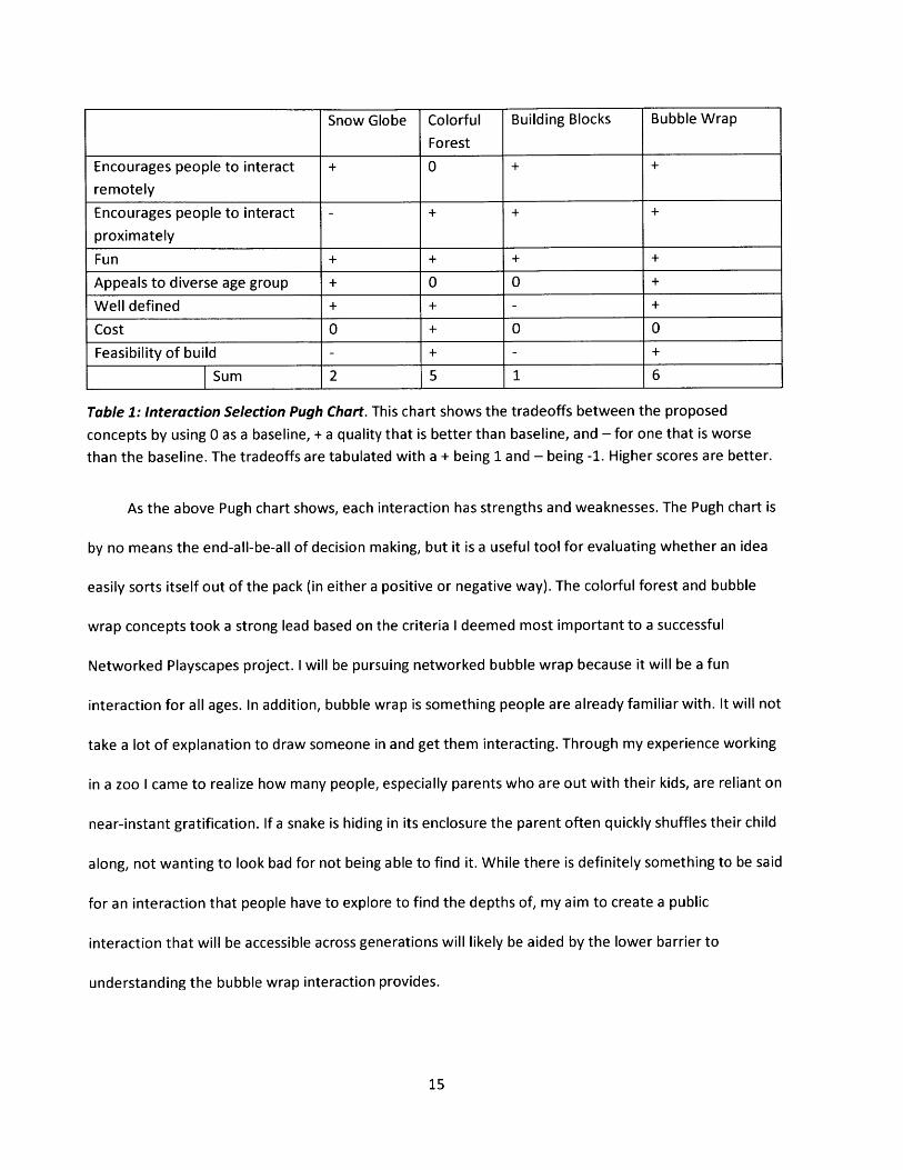
Snow Globe Colorful Building Blocks Bubble Wrap
Forest
Encourages people to interact + 0 + +
remotely
Encourages people to interact - + + +
proximately
Fun + + + +
Appeals to diverse age group + 0 0 +
Well defined + + - +
Cost 0 + 0 0
Feasibility of build - + - +
Sum 2 5 1 6
Table 1: Interaction Selection Pugh Chart. This chart shows the tradeoffs between the proposed
concepts by using 0 as a baseline, + a quality that is better than baseline, and - for one that is worse
than the baseline. The tradeoffs are tabulated with a + being 1 and - being -1. Higher scores are better.
As the above Pugh chart shows, each interaction has strengths and weaknesses. The Pugh chart is
by no means the end-all-be-all of decision making, but it is a useful tool for evaluating whether an idea
easily sorts itself out of the pack (in either a positive or negative way). The colorful forest and bubble
wrap concepts took a strong lead based on the criteria I deemed most important to a successful
Networked Playscapes project. I will be pursuing networked bubble wrap because it will be a fun
interaction for all ages. In addition, bubble wrap is something people are already familiar with. It will not
take a lot of explanation to draw someone in and get them interacting. Through my experience working
in a zoo I came to realize how many people, especially parents who are out with their kids, are reliant on
near-instant gratification. If a snake is hiding in its enclosure the parent often quickly shuffles their child
along, not wanting to look bad for not being able to find it. While there is definitely something to be said
for an interaction that people have to explore to find the depths of, my aim to create a public
interaction that will be accessible across generations will likely be aided by the lower barrier to
understanding the bubble wrap interaction provides.
15
3 DESIGN ITERATIONS
Having chosen to move forward with the bubble wrap concept, it is necessary to more fully define the
intended interaction and, based upon this, design the system. The overall idea is to create a pair of
networked "sheets" of bubble wrap. Pressing on a bubble will cause it to pop and also cause the
corresponding bubble on the sister sheet to pop. It must be possible for multiple people to pop bubbles
on the same sheet. Both sheets will function in an identical manner. When all bubbles are popped the
system will wait a set period of time and then reset. Once reset the bubbles will be full of air and ready
to be popped again.
Based on these interaction attributes, I identified the following requirements for the system.
First, the bubbles must be able to be popped many times such that people can keep playing and
interacting. The bubbles must be able to automatically reset to an air-filled, unpopped state. Popping a
bubble on one installation must make the analogous bubble pop on the paired installation. This must
happen independently of the state of the other bubbles. The interaction must be safe. Finally, the
interaction must be fun. As bubble wrap is already something that many people enjoy playing with, the
system should preserve the essential qualities of popping a standard piece of bubble wrap. This
requirement will be discussed further throughout this section, as it proved rather decisive.
With these requirements now established, I brainstormed many different ways to accomplish
them. I downselected to the most promising ideas. Through sketch-level prototyping and comparing the
tradeoffs of each, I selected which ideas to move forward with in the creation of a more fully realized
prototype. Design concepts and the reasoning behind why the final design was chosen are presented in
this section.
16
3.1 THE BUBBLES
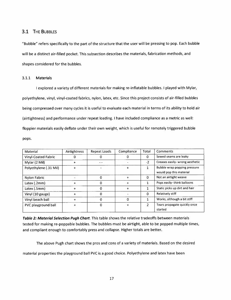
"Bubble" refers specifically to the part of the structure that the user will be pressing to pop. Each bubble
will be a distinct air-filled pocket. This subsection describes the materials, fabrication methods, and
shapes considered for the bubbles.
3.1.1 Materials
I explored a variety of different materials for making re-inflatable bubbles. I played with Mylar,
polyethylene, vinyl, vinyl-coated fabrics, nylon, latex, etc. Since this project consists of air-filled bubbles
being compressed over many cycles it is useful to evaluate each material in terms of its ability to hold air
(airtightness) and performance under repeat loading. I have included compliance as a metric as well:
floppier materials easily deflate under their own weight, which is useful for remotely triggered bubble
pops.
Material Airtightness Repeat Loads Compliance Total Comments
Vinyl-Coated Fabric 0 0 0 0 Sewed seams are leaky
Mylar (2 Mil) + -- - -2 Creases easily- wrong aesthetic
Polyethylene (.31 Mil) + - + 1 Bubble wrap popping pressurewould pop this material
Nylon Fabric - 0 + 0 Not an airtight weave
Latex (.2mm) + 0 + 1 Pops easily- think balloons
Latex (.5mm) + 0 + 1 Static picks up dirt and hair
Vinyl (10 gauge) + 0 - 0 Relatively stiff
Vinyl beach ball + 0 0 1 Works, although a bit stiff
PVC playground ball + 0 + 2 Tears propagate quickly oncestarted
Table 2: Material Selection Pugh Chart. This table shows the relative tradeoffs between materials
tested for making re-poppable bubbles. The bubbles must be airtight, able to be popped multiple times,
and compliant enough to comfortably press and collapse. Higher totals are better.
The above Pugh chart shows the pros and cons of a variety of materials. Based on the desired
material properties the playground ball PVC is a good choice. Polyethylene and latex have been
17
eliminated as bubble material choices due to their proneness to irreversibly popping. Moving forward, I
will prototype using both vinyl beach balls and PVC playground balls.
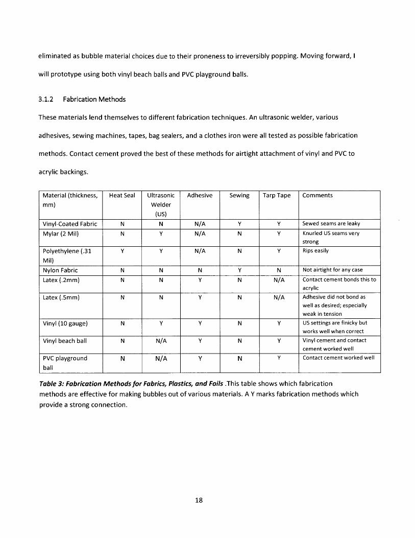
3.1.2 Fabrication Methods
These materials lend themselves to different fabrication techniques. An ultrasonic welder, various
adhesives, sewing machines, tapes, bag sealers, and a clothes iron were all tested as possible fabrication
methods. Contact cement proved the best of these methods for airtight attachment of vinyl and PVC to
acrylic backings.
Material (thickness, Heat Seal Ultrasonic Adhesive Sewing Tarp Tape Commentsmm) Welder
(US)
Vinyl-Coated Fabric N N N/A Y Y Sewed seams are leaky
Mylar (2 Mil) N Y N/A N Y Knurled US seams verystrong
Polyethylene (.31 Y Y N/A N Y Rips easily
Mil)Nylon Fabric N N N Y N Not airtight for any case
Latex (.2mm) N N Y N N/A contact cement bonds this toacrylic
Latex (.5mm) N N Y N N/A Adhesive did not bond aswell as desired; especiallyweak in tension
Vinyl (10 gauge) N Y Y N Y US settings are finicky butworks well when correct
Vinyl beach ball N N/A Y N Y Vinyl cement and contactcement worked well
PVC playground N N/A Y N Y Contact cement worked well
ball
Table 3: Fabrication Methods for Fabrics, Plastics, and Foils .This table shows which fabrication
methods are effective for making bubbles out of various materials. A Y marks fabrication methods which
provide a strong connection.
18
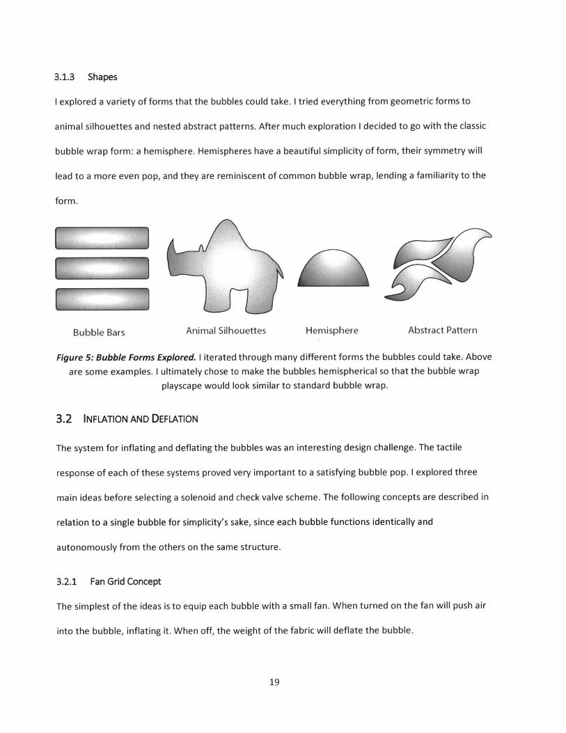
3.1.3 Shapes
I explored a variety of forms that the bubbles could take. I tried everything from geometric forms to
animal silhouettes and nested abstract patterns. After much exploration I decided to go with the classic
bubble wrap form: a hemisphere. Hemispheres have a beautiful simplicity of form, their symmetry will
lead to a more even pop, and they are reminiscent of common bubble wrap, lending a familiarity to the
form.
Bubble Bars Animal Silhouettes Hemisphere Abstract Pattern
Figure 5: Bubble Forms Explored. I iterated through many different forms the bubbles could take. Above
are some examples. I ultimately chose to make the bubbles hemispherical so that the bubble wrap
playscape would look similar to standard bubble wrap.
3.2 INFLATION AND DEFLATION
The system for inflating and deflating the bubbles was an interesting design challenge. The tactile
response of each of these systems proved very important to a satisfying bubble pop. I explored three
main ideas before selecting a solenoid and check valve scheme. The following concepts are described in
relation to a single bubble for simplicity's sake, since each bubble functions identically and
autonomously from the others on the same structure.
3.2.1 Fan Grid Concept
The simplest of the ideas is to equip each bubble with a small fan. When turned on the fan will push air
into the bubble, inflating it. When off, the weight of the fabric will deflate the bubble.
19
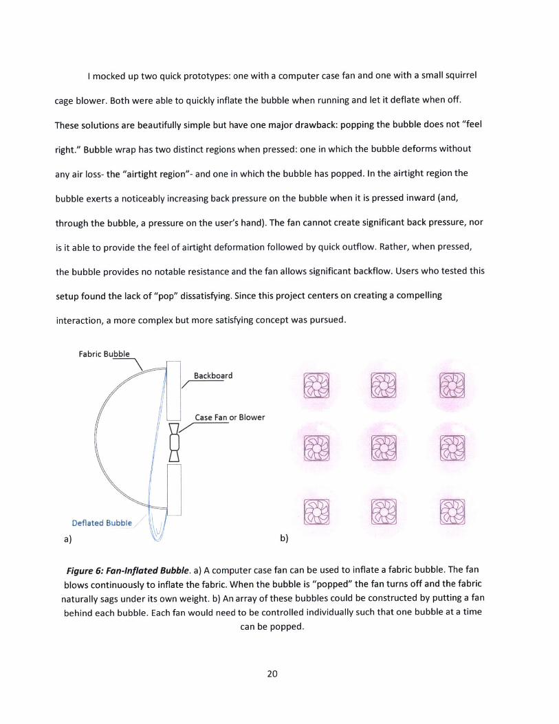
I mocked up two quick prototypes: one with a computer case fan and one with a small squirrel
cage blower. Both were able to quickly inflate the bubble when running and let it deflate when off.
These solutions are beautifully simple but have one major drawback: popping the bubble does not "feel
right." Bubble wrap has two distinct regions when pressed: one in which the bubble deforms without
any air loss- the "airtight region"- and one in which the bubble has popped. In the airtight region the
bubble exerts a noticeably increasing back pressure on the bubble when it is pressed inward (and,
through the bubble, a pressure on the user's hand). The fan cannot create significant back pressure, nor
is it able to provide the feel of airtight deformation followed by quick outflow. Rather, when pressed,
the bubble provides no notable resistance and the fan allows significant backflow. Users who tested this
setup found the lack of "pop" dissatisfying. Since this project centers on creating a compelling
interaction, a more complex but more satisfying concept was pursued.
Fabric Bubble
Backboard
Case Fan or Blower
Deflated Bubble
a) b)
Figure 6: Fan-inflated Bubble. a) A computer case fan can be used to inflate a fabric bubble. The fan
blows continuously to inflate the fabric. When the bubble is "popped" the fan turns off and the fabric
naturally sags under its own weight. b) An array of these bubbles could be constructed by putting a fan
behind each bubble. Each fan would need to be controlled individually such that one bubble at a time
can be popped.
20
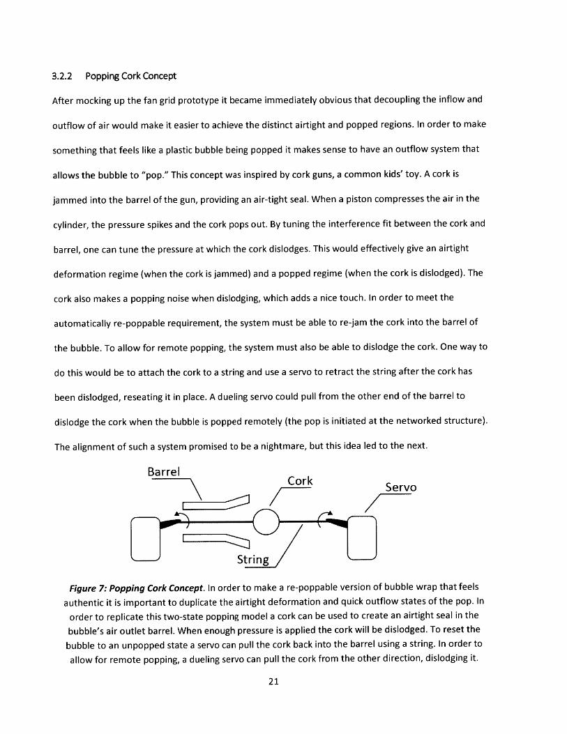
3.2.2 Popping Cork Concept
After mocking up the fan grid prototype it became immediately obvious that decoupling the inflow and
outflow of air would make it easier to achieve the distinct airtight and popped regions. In order to make
something that feels like a plastic bubble being popped it makes sense to have an outflow system that
allows the bubble to "pop." This concept was inspired by cork guns, a common kids' toy. A cork is
jammed into the barrel of the gun, providing an air-tight seal. When a piston compresses the air in the
cylinder, the pressure spikes and the cork pops out. By tuning the interference fit between the cork and
barrel, one can tune the pressure at which the cork dislodges. This would effectively give an airtight
deformation regime (when the cork is jammed) and a popped regime (when the cork is dislodged). The
cork also makes a popping noise when dislodging, which adds a nice touch. In order to meet the
automatically re-poppable requirement, the system must be able to re-jam the cork into the barrel of
the bubble. To allow for remote popping, the system must also be able to dislodge the cork. One way to
do this would be to attach the cork to a string and use a servo to retract the string after the cork has
been dislodged, reseating it in place. A dueling servo could pull from the other end of the barrel to
dislodge the cork when the bubble is popped remotely (the pop is initiated at the networked structure).
The alignment of such a system promised to be a nightmare, but this idea led to the next.
BarrelCork Servo
String
Figure 7: Popping Cork Concept. In order to make a re-poppable version of bubble wrap that feels
authentic it is important to duplicate the airtight deformation and quick outflow states of the pop. In
order to replicate this two-state popping model a cork can be used to create an airtight seal in the
bubble's air outlet barrel. When enough pressure is applied the cork will be dislodged. To reset the
bubble to an unpopped state a servo can pull the cork back into the barrel using a string. In order to
allow for remote popping, a dueling servo can pull the cork from the other direction, dislodging it.
21
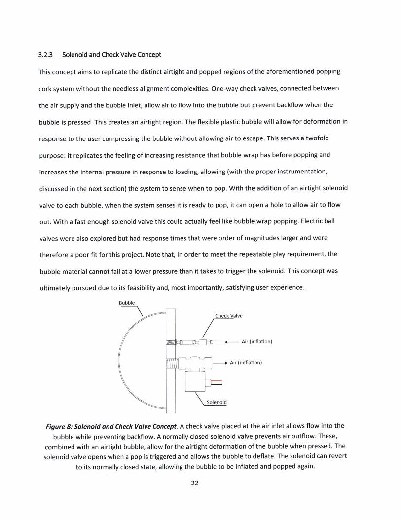
3.2.3 Solenoid and Check Valve Concept
This concept aims to replicate the distinct airtight and popped regions of the aforementioned popping
cork system without the needless alignment complexities. One-way check valves, connected between
the air supply and the bubble inlet, allow air to flow into the bubble but prevent backflow when the
bubble is pressed. This creates an airtight region. The flexible plastic bubble will allow for deformation in
response to the user compressing the bubble without allowing air to escape. This serves a twofold
purpose: it replicates the feeling of increasing resistance that bubble wrap has before popping and
increases the internal pressure in response to loading, allowing (with the proper instrumentation,
discussed in the next section) the system to sense when to pop. With the addition of an airtight solenoid
valve to each bubble, when the system senses it is ready to pop, it can open a hole to allow air to flow
out. With a fast enough solenoid valve this could actually feel like bubble wrap popping. Electric ball
valves were also explored but had response times that were order of magnitudes larger and were
therefore a poor fit for this project. Note that, in order to meet the repeatable play requirement, the
bubble material cannot fail at a lower pressure than it takes to trigger the solenoid. This concept was
ultimately pursued due to its feasibility and, most importantly, satisfying user experience.
Bubble
Check Valve
- }- +- Air (inflation)
.- Air (deflation)
Solenoid
Figure 8: Solenoid and Check Valve Concept. A check valve placed at the air inlet allows flow into the
bubble while preventing backflow. A normally closed solenoid valve prevents air outflow. These,
combined with an airtight bubble, allow for the airtight deformation of the bubble when pressed. The
solenoid valve opens when a pop is triggered and allows the bubble to deflate. The solenoid can revert
to its normally closed state, allowing the bubble to be inflated and popped again.
22
3.3 SENSING
In order for the solenoid-popping concept to work the system must be able to sense loading on the
bubble. Simply sensing whether someone is or is not pushing on the bubble defeats the point using a
solenoid to transition between the airtight and popped states of the bubble. An on/off presence sensing
scheme would not allow for a proper airtight region to exist under loading; rather, a threshold of loading
must be sensed. There are a variety of ways to incorporate these sensors- flex sensors in the fabric of
the bubble, force plates under the bubble, and internal pressure sensors are three such ways. The most
versatile method is measuring the internal pressure, as an increase above a certain pressure threshold
will prop the bubble regardless of whether the user is poking, pressing, or squeezing the bubble- loading
modes that a flex sensor or force plate would not be robust to. The two pressure sensing methods that I
explored are described below.
3.3.1 Pressure Transducers
Pressure transducers convert pressure readings to electrical signals. The sensors can measure from
vacuums to many thousands of psi. The bubbles are definitely on the lower side of this pressure range,
somewhere between atmospheric and the pressure it takes to inflate a basketball (around 8psi). Rather
than solve the nonlinear problem for a diverse set of materials, I took the faster and more exact route of
prototyping a few bubbles, inflating them with a bicycle pump, and measuring their internal pressures
when fully inflated and when being compressed under airtight conditions. The change in pressure was
on the order of mmH 20, which is negligible on a psi scale. Sensors of this level of sensitivity are certainly
possible to come by, but exceed the accessible price range I am aiming for- especially when the need for
a sensor for every bubble is taken into account.
23
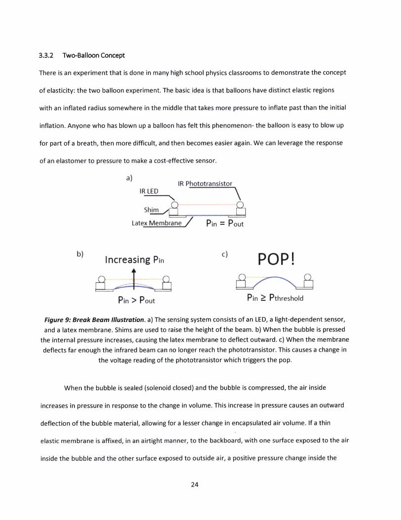
3.3.2 Two-Balloon Concept
There is an experiment that is done in many high school physics classrooms to demonstrate the concept
of elasticity: the two balloon experiment. The basic idea is that balloons have distinct elastic regions
with an inflated radius somewhere in the middle that takes more pressure to inflate past than the initial
inflation. Anyone who has blown up a balloon has felt this phenomenon- the balloon is easy to blow up
for part of a breath, then more difficult, and then becomes easier again. We can leverage the response
of an elastomer to pressure to make a cost-effective sensor.
a) IR PhototransistorIR LED
Shim
Latex Membrane Pin = Pout
b) Increasing Pin c) PO P!
Pin > Pout Pin Pthreshold
Figure 9: Break Beam Illustration. a) The sensing system consists of an LED, a light-dependent sensor,
and a latex membrane. Shims are used to raise the height of the beam. b) When the bubble is pressed
the internal pressure increases, causing the latex membrane to deflect outward. c) When the membrane
deflects far enough the infrared beam can no longer reach the phototransistor. This causes a change in
the voltage reading of the phototransistor which triggers the pop.
When the bubble is sealed (solenoid closed) and the bubble is compressed, the air inside
increases in pressure in response to the change in volume. This increase in pressure causes an outward
deflection of the bubble material, allowing for a lesser change in encapsulated air volume. If a thin
elastic membrane is affixed, in an airtight manner, to the backboard, with one surface exposed to the air
inside the bubble and the other surface exposed to outside air, a positive pressure change inside the
24
bubble will cause the membrane to deflect outward. The membrane deflection can be sensed with a
break-beam circuit- when the opaque membrane deflects far enough it will block light from getting to
the sensor, which, in tandem with a voltage divider, allows the ON/OFF state of the beam to be read.
Since a greater deflection of the membrane is due to increased input pressure, the popping pressure of
the bubble (the point at which the sensor reads a beam break) can be tuned by adjusting the distance of
the break beam sensor from the resting plane of the membrane. Positioning the sensor further from the
membrane will result in a higher threshold pressure. For a small surface area and a properly elastic
material, such as latex, this will cause an imperceptible increase in volume of the airtight region. The
user will still feel the increase in back pressure as more force is exerted on the bubble, therefore this
sensing method does not disturb the feel popping the bubble. This is a very economical and simple way
to detect small pressure changes in the low pressure range these bubbles will operate at, therefore it
makes the most sense to pursue for the final prototype.
4 PROOF OF CONCEPT PROTOTYPE
The proof of concept prototype is meant to demonstrate that the bubble popping system performs as
expected and has a satisfying feel for users. Quick, single-bubble prototypes can be iterated through to
find a suitably satisfying popping interaction before a full-scale prototype is constructed. I built the proof
of concept re-poppable bubble using vinyl as the bubble skin, solenoids for deflation, check valves for
unidirectional inflation, and a latex pressure sensor. A discussion on each of these subsystems can be
found in section 3. The following text will focus on physical implementation.
4.1 THE BUBBLES
The bubbles for this system must be airtight and pliable. I made many protype bubbles using various
vinyls, adhesives, and backings. After many iterations I found that modifying preexisting vinyl balls was a
25
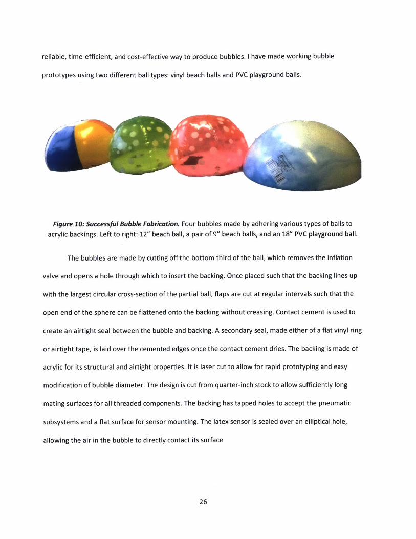
reliable, time-efficient, and cost-effective way to produce bubbles. I have made working bubble
prototypes using two different ball types: vinyl beach balls and PVC playground balls.
Figure 10: Successful Bubble Fabrication. Four bubbles made by adhering various types of balls to
acrylic backings. Left to right: 12" beach ball, a pair of 9" beach balls, and an 18" PVC playground ball.
The bubbles are made by cutting off the bottom third of the ball, which removes the inflation
valve and opens a hole through which to insert the backing. Once placed such that the backing lines up
with the largest circular cross-section of the partial ball, flaps are cut at regular intervals such that the
open end of the sphere can be flattened onto the backing without creasing. Contact cement is used to
create an airtight seal between the bubble and backing. A secondary seal, made either of a flat vinyl ring
or airtight tape, is laid over the cemented edges once the contact cement dries. The backing is made of
acrylic for its structural and airtight properties. It is laser cut to allow for rapid prototyping and easy
modification of bubble diameter. The design is cut from quarter-inch stock to allow sufficiently long
mating surfaces for all threaded components. The backing has tapped holes to accept the pneumatic
subsystems and a flat surface for sensor mounting. The latex sensor is sealed over an elliptical hole,
allowing the air in the bubble to directly contact its surface
26
S8.50
/ .91 THRU ALL3/4 NPT
2.00
2.00
.44 THRU ALL1/4 NPT
1.00 2.00 /NP
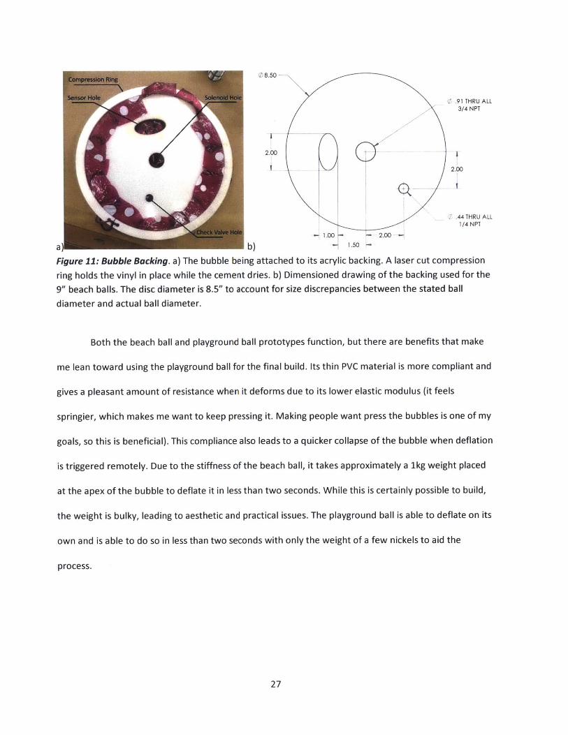
a) b) 1.50
Figure 11: Bubble Backing. a) The bubble being attached to its acrylic backing. A laser cut compression
ring holds the vinyl in place while the cement dries. b) Dimensioned drawing of the backing used for the
9" beach balls. The disc diameter is 8.5" to account for size discrepancies between the stated ball
diameter and actual ball diameter.
Both the beach ball and playground ball prototypes function, but there are benefits that make
me lean toward using the playground ball for the final build. Its thin PVC material is more compliant and
gives a pleasant amount of resistance when it deforms due to its lower elastic modulus (it feels
springier, which makes me want to keep pressing it. Making people want press the bubbles is one of my
goals, so this is beneficial). This compliance also leads to a quicker collapse of the bubble when deflation
is triggered remotely. Due to the stiffness of the beach ball, it takes approximately a 1kg weight placed
at the apex of the bubble to deflate it in less than two seconds. While this is certainly possible to build,
the weight is bulky, leading to aesthetic and practical issues. The playground ball is able to deflate on its
own and is able to do so in less than two seconds with only the weight of a few nickels to aid the
process.
27
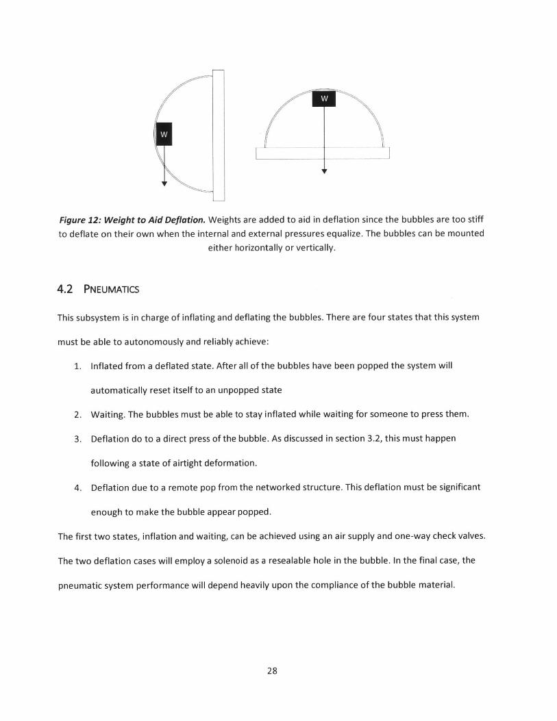
Figure 12: Weight to Aid Deflation. Weights are added to aid in deflation since the bubbles are too stiff
to deflate on their own when the internal and external pressures equalize. The bubbles can be mounted
either horizontally or vertically.
4.2 PNEUMATICS
This subsystem is in charge of inflating and deflating the bubbles. There are four states that this system
must be able to autonomously and reliably achieve:
1. Inflated from a deflated state. After all of the bubbles have been popped the system will
automatically reset itself to an unpopped state
2. Waiting. The bubbles must be able to stay inflated while waiting for someone to press them.
3. Deflation do to a direct press of the bubble. As discussed in section 3.2, this must happen
following a state of airtight deformation.
4. Deflation due to a remote pop from the networked structure. This deflation must be significant
enough to make the bubble appear popped.
The first two states, inflation and waiting, can be achieved using an air supply and one-way check valves.
The two deflation cases will employ a solenoid as a resealable hole in the bubble. In the final case, the
pneumatic system performance will depend heavily upon the compliance of the bubble material.
28
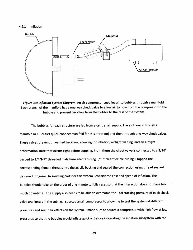
4.2.1 Inflation
Bubble Manifold
Check ValveComp
Air Compressor
Figure 13: Inflation System Diagram. An air compressor supplies air to bubbles through a manifold.
Each branch of the manifold has a one-way check valve to allow air to flow from the compressor to the
bubble and prevent backflow from the bubble to the rest of the system.
The bubbles for each structure are fed from a central air supply. The air travels through a
manifold (a 10-outlet quick-connect manifold for this iteration) and then through one-way check valves.
These valves prevent unwanted backflow, allowing for inflation, airtight waiting, and an airtight
deformation state that occurs right before popping. From there the check valve is connected to a 3/16"
barbed to 1/4"NPT threaded male hose adapter using 3/16" clear flexible tubing. I tapped the
corresponding female threads into the acrylic backing and sealed the connection using thread sealant
designed for gases. In sourcing parts for this system I considered cost and speed of inflation. The
bubbles should take on the order of one minute to fully reset so that the interaction does not have too
much downtime. The supply also needs to be able to overcome the ipsi cracking pressure of each check
valve and losses in the tubing. I sourced an air compressor to allow me to test the system at different
pressures and see their effects on the system. I made sure to source a compressor with high flow at low
pressures so that the bubbles would inflate quickly. Before integrating the inflation subsystem with the
29
rest of the bubble system, I checked that the lines and connections were airtight and that the flow rate
was acceptable by inflating a set of ten latex party balloons, one for each output hose.
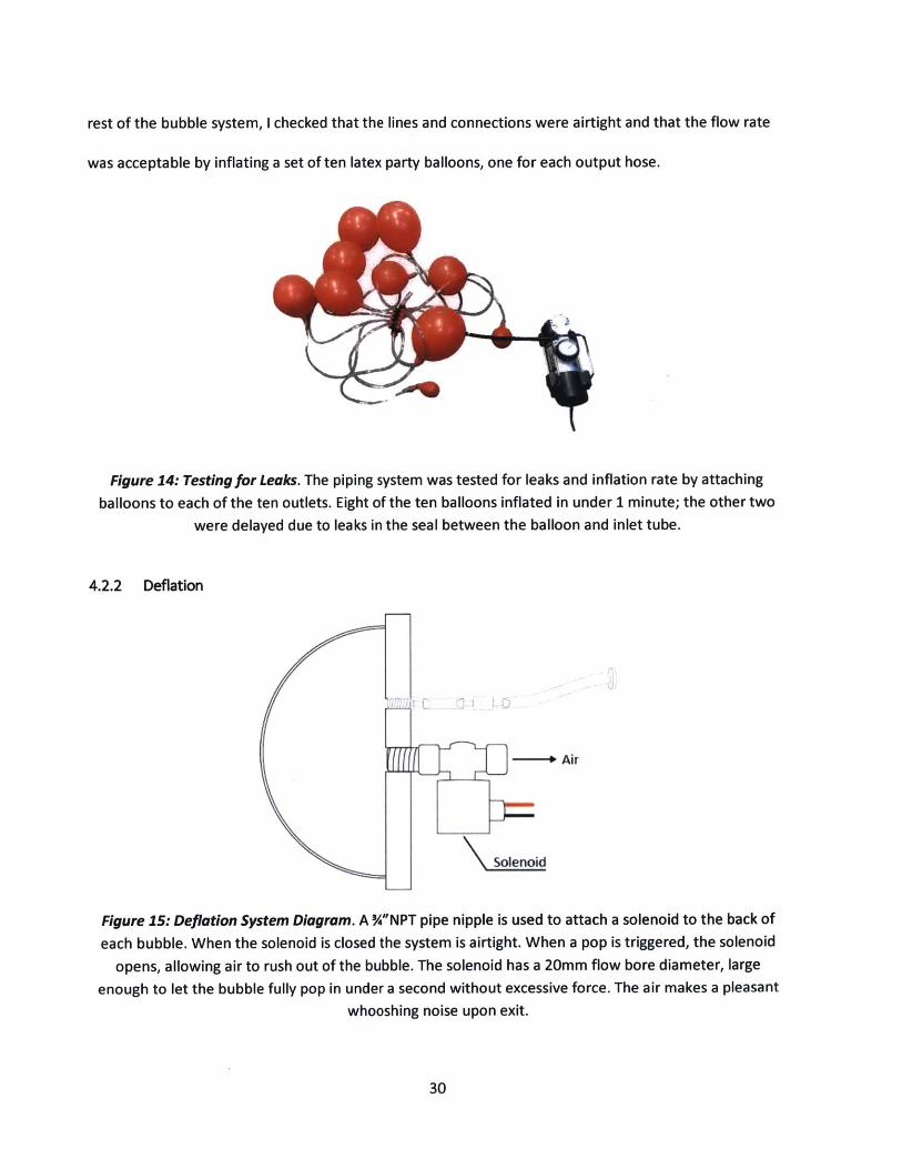
Figure 14: Testingfor Leaks. The piping system was tested for leaks and inflation rate by attaching
balloons to each of the ten outlets. Eight of the ten balloons inflated in under 1 minute; the other two
were delayed due to leaks in the seal between the balloon and inlet tube.
4.2.2 Deflation
-- Air
Solenoid
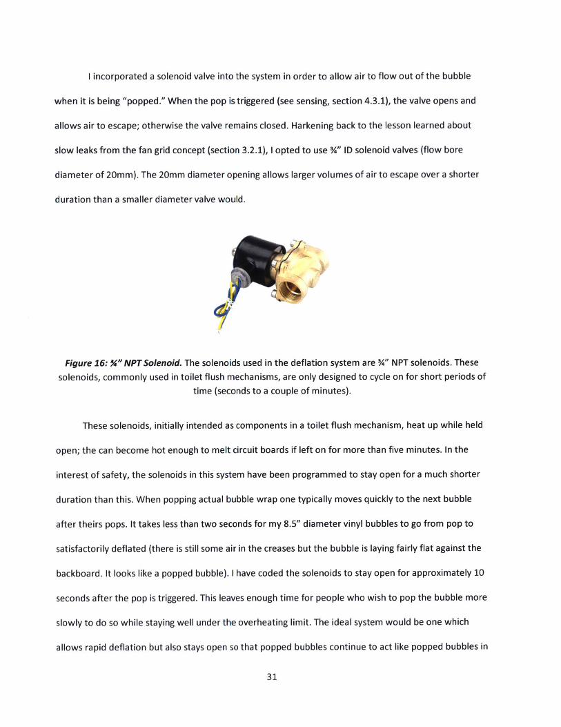
Figure 15: Deflation System Diagram. A %"NPT pipe nipple is used to attach a solenoid to the back of
each bubble. When the solenoid is closed the system is airtight. When a pop is triggered, the solenoid
opens, allowing air to rush out of the bubble. The solenoid has a 20mm flow bore diameter, large
enough to let the bubble fully pop in under a second without excessive force. The air makes a pleasant
whooshing noise upon exit.
30
I-- --- M- - - - -- ":
I incorporated a solenoid valve into the system in order to allow air to flow out of the bubble
when it is being "popped." When the pop is triggered (see sensing, section 4.3.1), the valve opens and
allows air to escape; otherwise the valve remains closed. Harkening back to the lesson learned about
slow leaks from the fan grid concept (section 3.2.1), I opted to use %" ID solenoid valves (flow bore
diameter of 20mm). The 20mm diameter opening allows larger volumes of air to escape over a shorter
duration than a smaller diameter valve would.
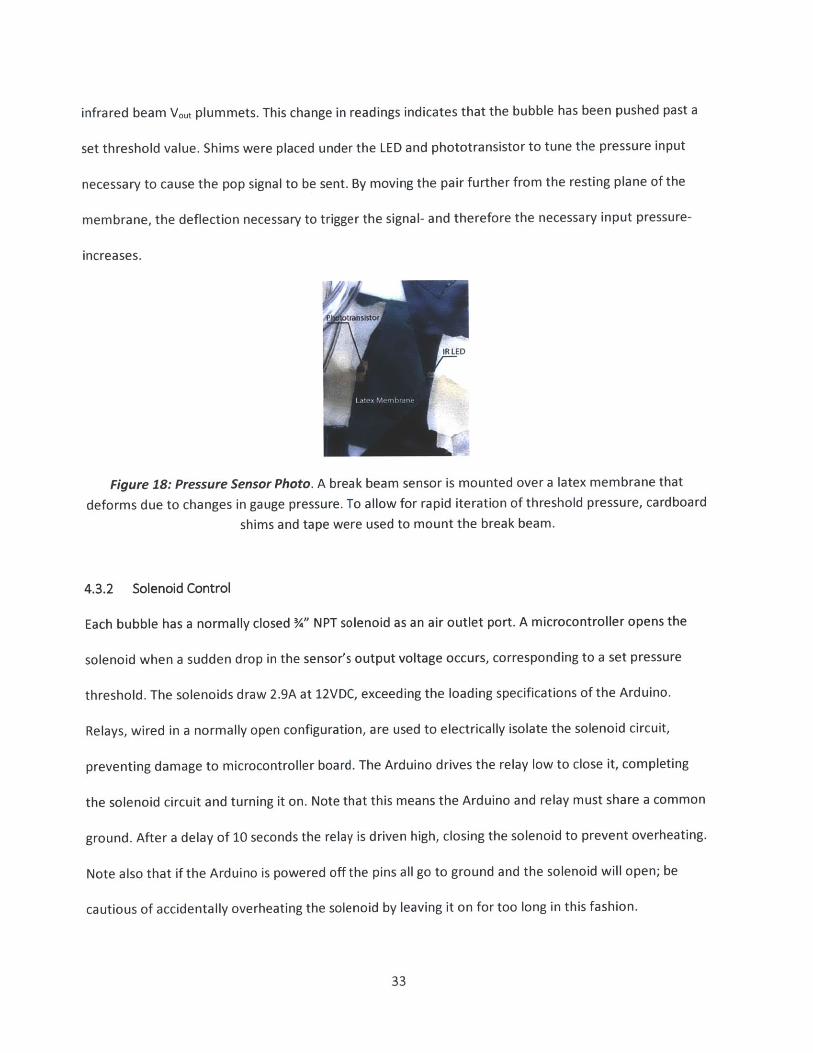
Figure 16: %"NPT Solenoid. The solenoids used in the deflation system are %" NPT solenoids. These
solenoids, commonly used in toilet flush mechanisms, are only designed to cycle on for short periods of
time (seconds to a couple of minutes).
These solenoids, initially intended as components in a toilet flush mechanism, heat up while held
open; the can become hot enough to melt circuit boards if left on for more than five minutes. In the
interest of safety, the solenoids in this system have been programmed to stay open for a much shorter
duration than this. When popping actual bubble wrap one typically moves quickly to the next bubble
after theirs pops. It takes less than two seconds for my 8.5" diameter vinyl bubbles to go from pop to
satisfactorily deflated (there is still some air in the creases but the bubble is laying fairly flat against the
backboard. It looks like a popped bubble). I have coded the solenoids to stay open for approximately 10
seconds after the pop is triggered. This leaves enough time for people who wish to pop the bubble more
slowly to do so while staying well under the overheating limit. The ideal system would be one which
allows rapid deflation but also stays open so that popped bubbles continue to act like popped bubbles in
31
real bubble wrap- one can go back an squeeze out the rest of the air or pull on the bubbles to draw air
back in. While leaving a smaller solenoid open for extended periods of time can be fine, this is not
practical for solenoids of this larger size due to heating concerns. This minor flaw is far outweighed by
the significantly faster emptying of the bubble and order of magnitude cheaper pricing compared to
other valves of comparable size.
4.3 ELECTRONICS
The system is run on an Arduino Mega. This section pertains to wiring and coding for the sensor and
solenoid subassemblies.
4.3.1 Sensing
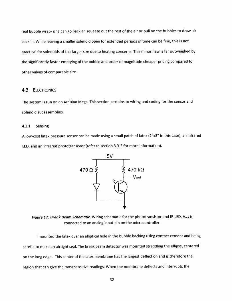
A low-cost latex pressure sensor can be made using a small patch of latex (2"x3" in this case), an infrared
LED, and an infrared phototransistor (refer to section 3.3.2 for more information).
5V
4700 470kQVout
Figure 17: Break Beam Schematic. Wiring schematic for the phototransistor and IR LED. Vout is
connected to an analog input pin on the microcontroller.
I mounted the latex over an elliptical hole in the bubble backing using contact cement and being
careful to make an airtight seal. The break beam detector was mounted straddling the ellipse, centered
on the long edge. This center of the latex membrane has the largest deflection and is therefore the
region that can give the most sensitive readings. When the membrane deflects and interrupts the
32
infrared beam V 0ut plummets. This change in readings indicates that the bubble has been pushed past a
set threshold value. Shims were placed under the LED and phototransistor to tune the pressure input
necessary to cause the pop signal to be sent. By moving the pair further from the resting plane of the
membrane, the deflection necessary to trigger the signal- and therefore the necessary input pressure-
increases.
R LED
Figure 18: Pressure Sensor Photo. A break beam sensor is mounted over a latex membrane that
deforms due to changes in gauge pressure. To allow for rapid iteration of threshold pressure, cardboard
shims and tape were used to mount the break beam.
4.3.2 Solenoid Control
Each bubble has a normally closed %" NPT solenoid as an air outlet port. A microcontroller opens the
solenoid when a sudden drop in the sensor's output voltage occurs, corresponding to a set pressure
threshold. The solenoids draw 2.9A at 12VDC, exceeding the loading specifications of the Arduino.
Relays, wired in a normally open configuration, are used to electrically isolate the solenoid circuit,
preventing damage to microcontroller board. The Arduino drives the relay low to close it, completing
the solenoid circuit and turning it on. Note that this means the Arduino and relay must share a common
ground. After a delay of 10 seconds the relay is driven high, closing the solenoid to prevent overheating.
Note also that if the Arduino is powered off the pins all go to ground and the solenoid will open; be
cautious of accidentally overheating the solenoid by leaving it on for too long in this fashion.
33
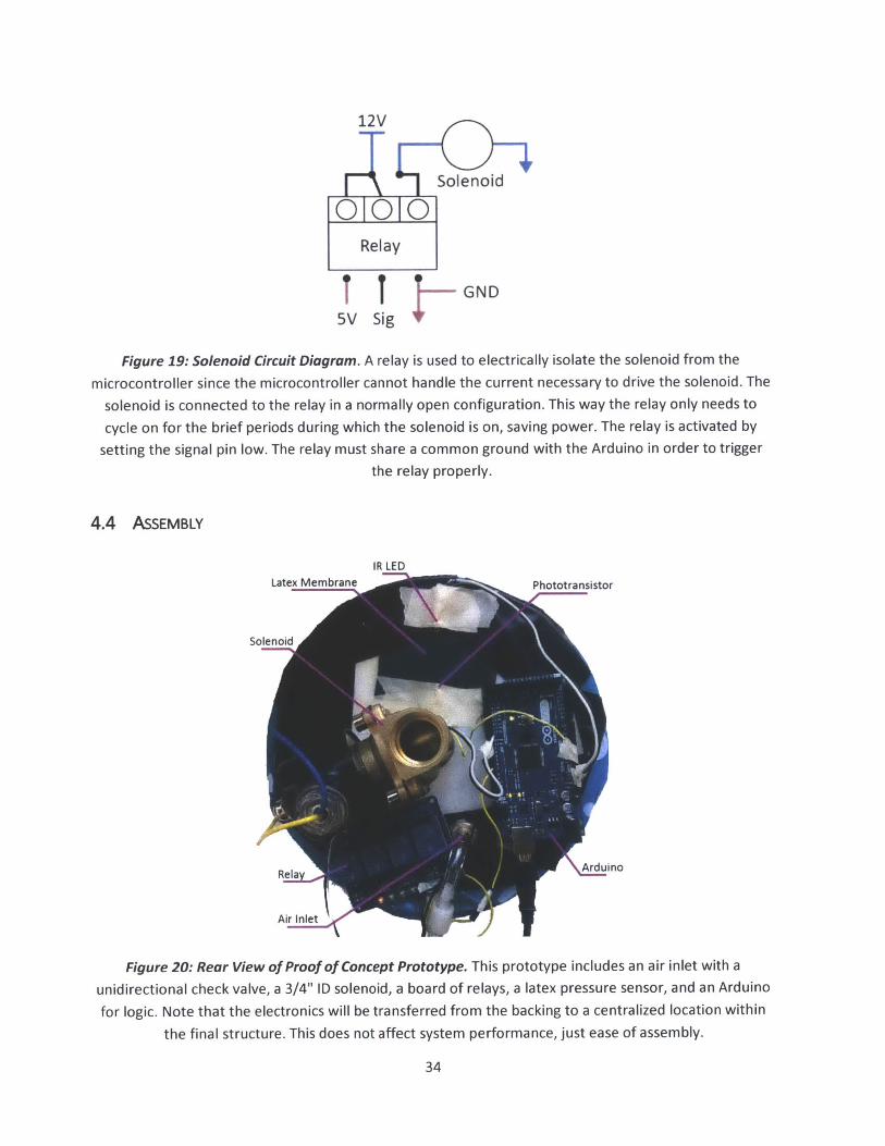
12V
Solenoid
Relay
T T -GND5V Sig
Figure 19: Solenoid Circuit Diagram. A relay is used to electrically isolate the solenoid from the
microcontroller since the microcontroller cannot handle the current necessary to drive the solenoid. The
solenoid is connected to the relay in a normally open configuration. This way the relay only needs to
cycle on for the brief periods during which the solenoid is on, saving power. The relay is activated by
setting the signal pin low. The relay must share a common ground with the Arduino in order to trigger
the relay properly.
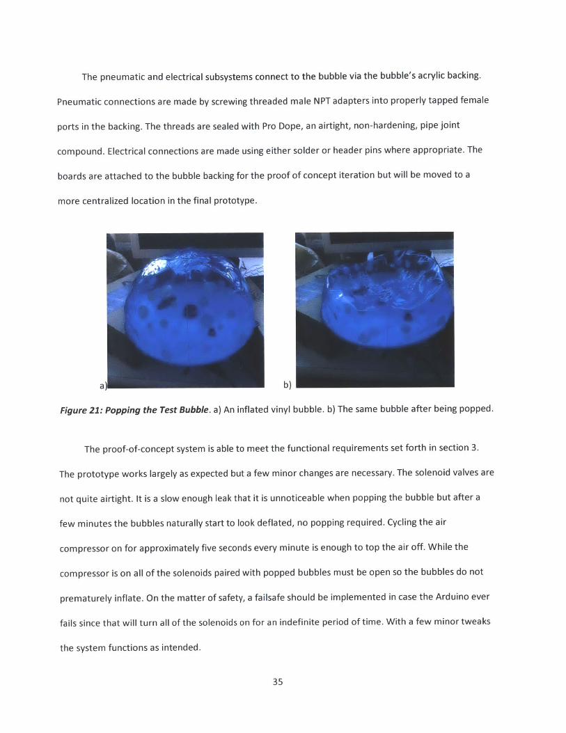
4.4 ASSEMBLY
IR LEDLatex Membrane Phototransistor
Solenoid
Rela Arduino
Air Inlet-
Figure 20: Rear View of Proof of Concept Prototype. This prototype includes an air inlet with a
unidirectional check valve, a 3/4" ID solenoid, a board of relays, a latex pressure sensor, and an Arduino
for logic. Note that the electronics will be transferred from the backing to a centralized location within
the final structure. This does not affect system performance, just ease of assembly.
34
The pneumatic and electrical subsystems connect to the bubble via the bubble's acrylic backing.
Pneumatic connections are made by screwing threaded male NPT adapters into properly tapped female
ports in the backing. The threads are sealed with Pro Dope, an airtight, non-hardening, pipe joint
compound. Electrical connections are made using either solder or header pins where appropriate. The
boards are attached to the bubble backing for the proof of concept iteration but will be moved to a
more centralized location in the final prototype.
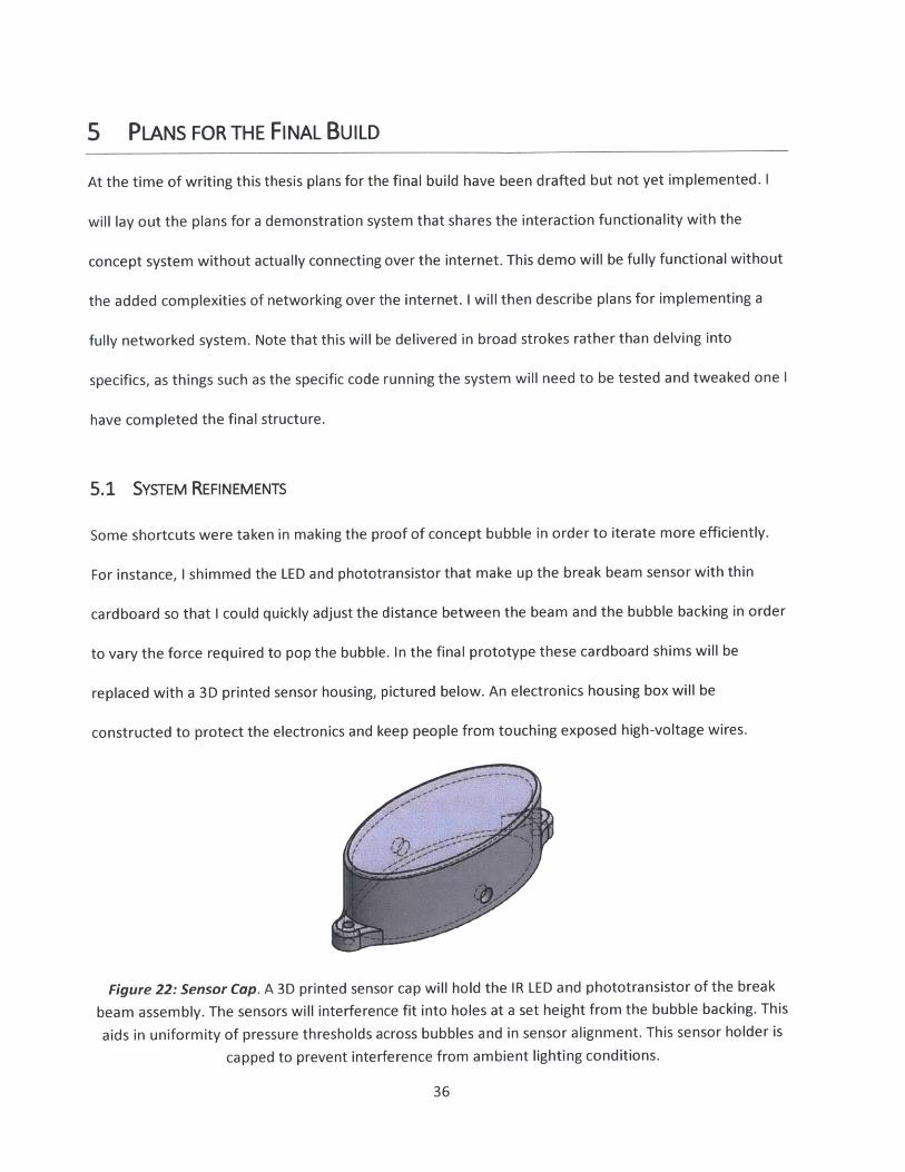
a b)
Figure 21: Popping the Test Bubble. a) An inflated vinyl bubble. b) The same bubble after being popped.
The proof-of-concept system is able to meet the functional requirements set forth in section 3.
The prototype works largely as expected but a few minor changes are necessary. The solenoid valves are
not quite airtight. It is a slow enough leak that it is unnoticeable when popping the bubble but after a
few minutes the bubbles naturally start to look deflated, no popping required. Cycling the air
compressor on for approximately five seconds every minute is enough to top the air off. While the
compressor is on all of the solenoids paired with popped bubbles must be open so the bubbles do not
prematurely inflate. On the matter of safety, a failsafe should be implemented in case the Arduino ever
fails since that will turn all of the solenoids on for an indefinite period of time. With a few minor tweaks
the system functions as intended.
35
5 PLANS FOR THE FINAL BUILD
At the time of writing this thesis plans for the final build have been drafted but not yet implemented. I
will lay out the plans for a demonstration system that shares the interaction functionality with the
concept system without actually connecting over the internet. This demo will be fully functional without
the added complexities of networking over the internet. I will then describe plans for implementing a
fully networked system. Note that this will be delivered in broad strokes rather than delving into
specifics, as things such as the specific code running the system will need to be tested and tweaked one I
have completed the final structure.
5.1 SYSTEM REFINEMENTS
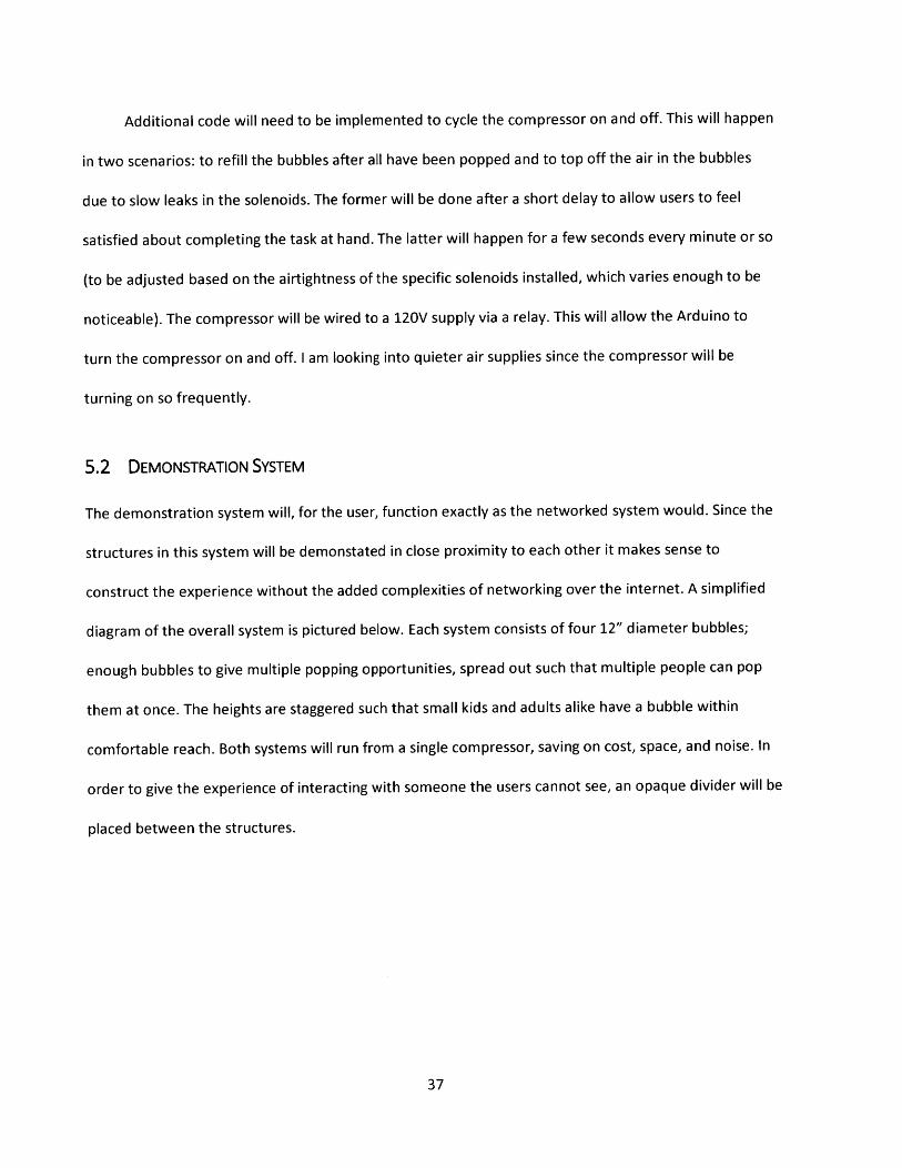
Some shortcuts were taken in making the proof of concept bubble in order to iterate more efficiently.
For instance, I shimmed the LED and phototransistor that make up the break beam sensor with thin
cardboard so that I could quickly adjust the distance between the beam and the bubble backing in order
to vary the force required to pop the bubble. In the final prototype these cardboard shims will be
replaced with a 3D printed sensor housing, pictured below. An electronics housing box will be
constructed to protect the electronics and keep people from touching exposed high-voltage wires.
Figure 22: Sensor Cap. A 3D printed sensor cap will hold the IR LED and phototransistor of the break
beam assembly. The sensors will interference fit into holes at a set height from the bubble backing. This
aids in uniformity of pressure thresholds across bubbles and in sensor alignment. This sensor holder is
capped to prevent interference from ambient lighting conditions.
36
Additional code will need to be implemented to cycle the compressor on and off. This will happen
in two scenarios: to refill the bubbles after all have been popped and to top off the air in the bubbles
due to slow leaks in the solenoids. The former will be done after a short delay to allow users to feel
satisfied about completing the task at hand. The latter will happen for a few seconds every minute or so
(to be adjusted based on the airtightness of the specific solenoids installed, which varies enough to be
noticeable). The compressor will be wired to a 120V supply via a relay. This will allow the Arduino to
turn the compressor on and off. I am looking into quieter air supplies since the compressor will be
turning on so frequently.
5.2 DEMONSTRATION SYSTEM
The demonstration system will, for the user, function exactly as the networked system would. Since the
structures in this system will be demonstated in close proximity to each other it makes sense to
construct the experience without the added complexities of networking over the internet. A simplified
diagram of the overall system is pictured below. Each system consists of four 12" diameter bubbles;
enough bubbles to give multiple popping opportunities, spread out such that multiple people can pop
them at once. The heights are staggered such that small kids and adults alike have a bubble within
comfortable reach. Both systems will run from a single compressor, saving on cost, space, and noise. In
order to give the experience of interacting with someone the users cannot see, an opaque divider will be
placed between the structures.
37
77
K
/ // / Air Compressor
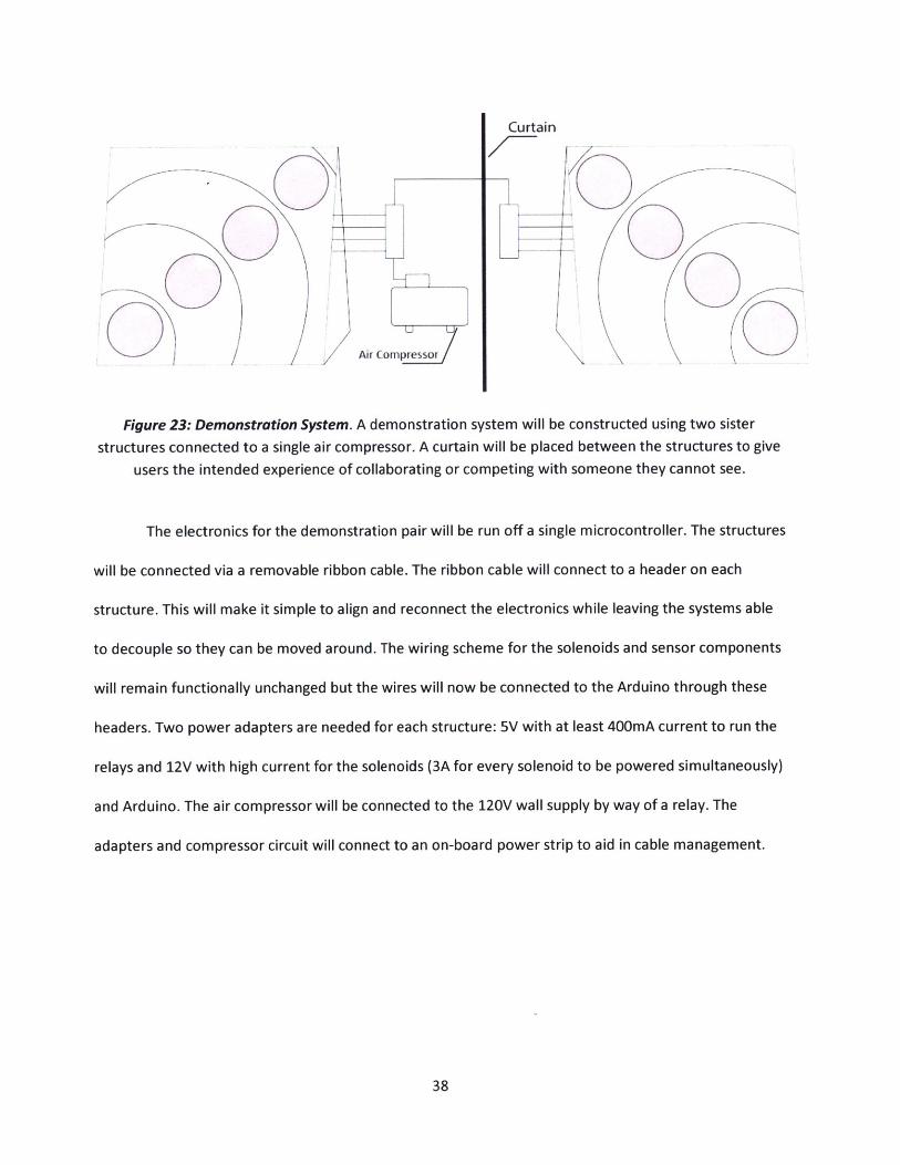
Figure 23: Demonstration System. A demonstration system will be constructed using two sister
structures connected to a single air compressor. A curtain will be placed between the structures to give
users the intended experience of collaborating or competing with someone they cannot see.
The electronics for the demonstration pair will be run off a single microcontroller. The structures
will be connected via a removable ribbon cable. The ribbon cable will connect to a header on each
structure. This will make it simple to align and reconnect the electronics while leaving the systems able
to decouple so they can be moved around. The wiring scheme for the solenoids and sensor components
will remain functionally unchanged but the wires will now be connected to the Arduino through these
headers. Two power adapters are needed for each structure: 5V with at least 400mA current to run the
relays and 12V with high current for the solenoids (3A for every solenoid to be powered simultaneously)
and Arduino. The air compressor will be connected to the 120V wall supply by way of a relay. The
adapters and compressor circuit will connect to an on-board power strip to aid in cable management.
38
Curtain
0o 0o
0 0 - 0
000000
Power Strip Arduino, Arduino Power Strip
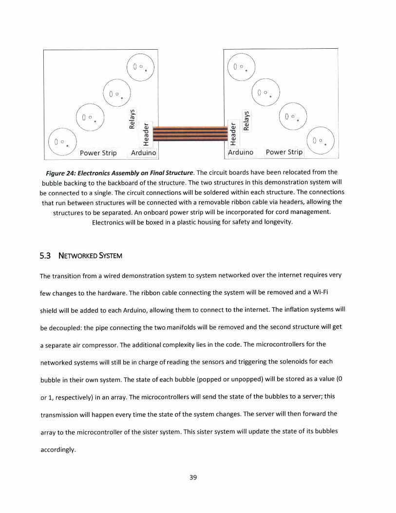
Figure 24: Electronics Assembly on Final Structure. The circuit boards have been relocated from the
bubble backing to the backboard of the structure. The two structures in this demonstration system will
be connected to a single. The circuit connections will be soldered within each structure. The connections
that run between structures will be connected with a removable ribbon cable via headers, allowing the
structures to be separated. An onboard power strip will be incorporated for cord management.
Electronics will be boxed in a plastic housing for safety and longevity.
5.3 NETWORKED SYSTEM
The transition from a wired demonstration system to system networked over the internet requires very
few changes to the hardware. The ribbon cable connecting the system will be removed and a Wi-Fi
shield will be added to each Arduino, allowing them to connect to the internet. The inflation systems will
be decoupled: the pipe connecting the two manifolds will be removed and the second structure will get
a separate air compressor. The additional complexity lies in the code. The microcontrollers for the
networked systems will still be in charge of reading the sensors and triggering the solenoids for each
bubble in their own system. The state of each bubble (popped or unpopped) will be stored as a value (0
or 1, respectively) in an array. The microcontrollers will send the state of the bubbles to a server; this
transmission will happen every time the state of the system changes. The server will then forward the
array to the microcontroller of the sister system. This sister system will update the state of its bubbles
accordingly.
39
i
Interface Interface
JSON JSON
JSON JSON
Microcontroller #1 Server Microcontroller #2
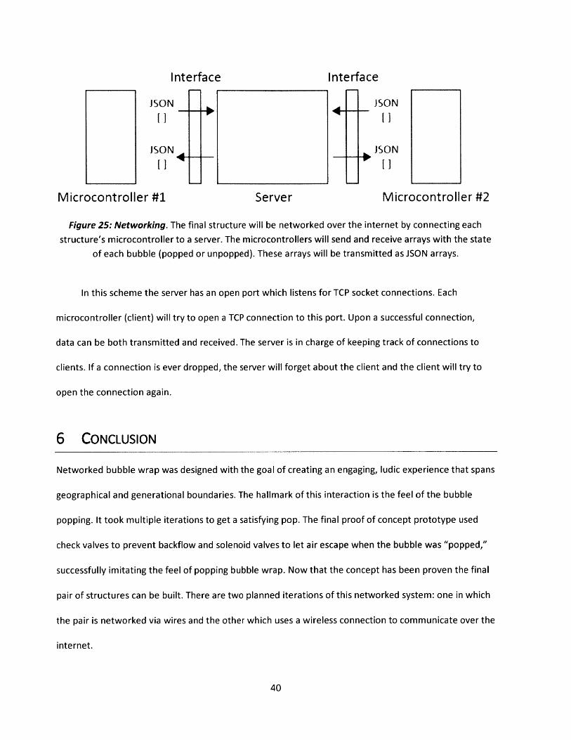
Figure 25: Networking. The final structure will be networked over the internet by connecting each
structure's microcontroller to a server. The microcontrollers will send and receive arrays with the state
of each bubble (popped or unpopped). These arrays will be transmitted as JSON arrays.
In this scheme the server has an open port which listens for TCP socket connections. Each
microcontroller (client) will try to open a TCP connection to this port. Upon a successful connection,
data can be both transmitted and received. The server is in charge of keeping track of connections to
clients. If a connection is ever dropped, the server will forget about the client and the client will try to
open the connection again.
6 CONCLUSION
Networked bubble wrap was designed with the goal of creating an engaging, ludic experience that spans
geographical and generational boundaries. The hallmark of this interaction is the feel of the bubble
popping. It took multiple iterations to get a satisfying pop. The final proof of concept prototype used
check valves to prevent backflow and solenoid valves to let air escape when the bubble was "popped,"
successfully imitating the feel of popping bubble wrap. Now that the concept has been proven the final
pair of structures can be built. There are two planned iterations of this networked system: one in which
the pair is networked via wires and the other which uses a wireless connection to communicate over the
internet.
40
This piece fits neatly into the Networked Playscapes puzzle. It breaks the mold of the traditional
sandbox-swing-jungle gym model of American playgrounds and combines electronics and telepresence
with a playful physical interaction to create a new opportunity for public play. In prototyping a bubble-
wrap inspired design that focuses on tactile interaction I was able to explore a new design space within
the Networked Playscapes continuum. The use of relays and solenoids in the air outlet system also lends
an interesting auditory layer to the interaction: the sound of the solenoid clicking and the air whooshing
out of the bubble has been described as "yummy." Once the system is constructed, user testing must be
conducted to validate whether this interaction appeals to a wide variety of ages, encourages both
remote and direct play, and can cross cultural boundaries.
41
7 BIBLIOGRAPHY
Dublon, G., & Portocarrero, E. (2014). Listentree: Audio-Haptic Display in the Natural Enviroinment.
Proc. 20th International Conference on Auditory Display (ICAD-2014).
Portocarrero, E. (To be published in 2016). Networked Playscapes. MIT Media Lab, Thesis.
42