Embed Size (px)
Citation preview
FUTURE DEVELOPMENT OF IMT SYSTEMS
Sergo ShavgulidzeGNCC/GTU
ITU-R, Vice-Chairman of Study Group 5
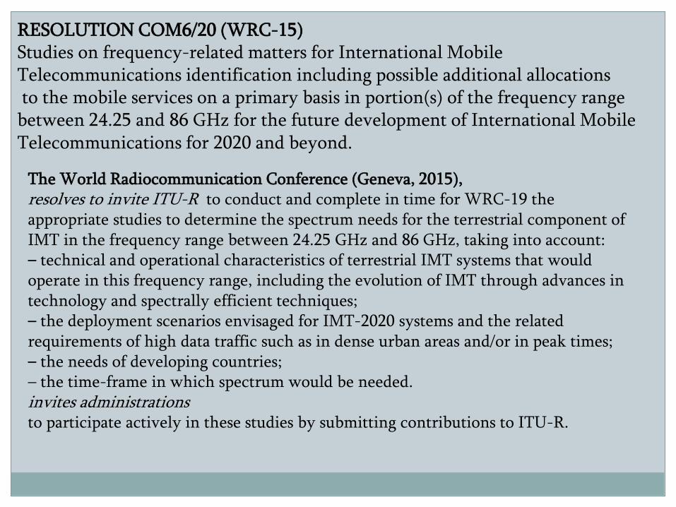
RESOLUTION COM6/20 (WRC-15)Studies on frequency-related matters for International Mobile Telecommunications identification including possible additional allocationsto the mobile services on a primary basis in portion(s) of the frequency range
between 24.25 and 86 GHz for the future development of International Mobile Telecommunications for 2020 and beyond.
The World Radiocommunication Conference (Geneva, 2015),resolves to invite ITU-R to conduct and complete in time for WRC-19 the appropriate studies to determine the spectrum needs for the terrestrial component of IMT in the frequency range between 24.25 GHz and 86 GHz, taking into account:– technical and operational characteristics of terrestrial IMT systems that would operate in this frequency range, including the evolution of IMT through advances in technology and spectrally efficient techniques;– the deployment scenarios envisaged for IMT-2020 systems and the related requirements of high data traffic such as in dense urban areas and/or in peak times;– the needs of developing countries;– the time-frame in which spectrum would be needed.invites administrationsto participate actively in these studies by submitting contributions to ITU-R.
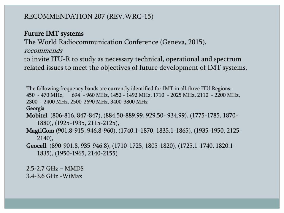
RECOMMENDATION 207 (REV.WRC-15)
Future IMT systemsThe World Radiocommunication Conference (Geneva, 2015),recommendsto invite ITU-R to study as necessary technical, operational and spectrum related issues to meet the objectives of future development of IMT systems.
The following frequency bands are currently identified for IMT in all three ITU Regions:450 - 470 MHz, 694 - 960 MHz, 1452 - 1492 MHz, 1710 - 2025 MHz, 2110 - 2200 MHz, 2300 - 2400 MHz, 2500-2690 MHz, 3400-3800 MHzGeorgia
Mobitel (806-816, 847-847), (884.50-889.99, 929.50- 934.99), (1775-1785, 1870-1880), (1925-1935, 2115-2125),
MagtiCom (901.8-915, 946.8-960), (1740.1-1870, 1835.1-1865), (1935-1950, 2125-2140),
Geocell (890-901.8, 935-946.8), (1710-1725, 1805-1820), (1725.1-1740, 1820.1-1835), (1950-1965, 2140-2155)
2.5-2.7 GHz – MMDS3.4-3.6 GHz -WiMax
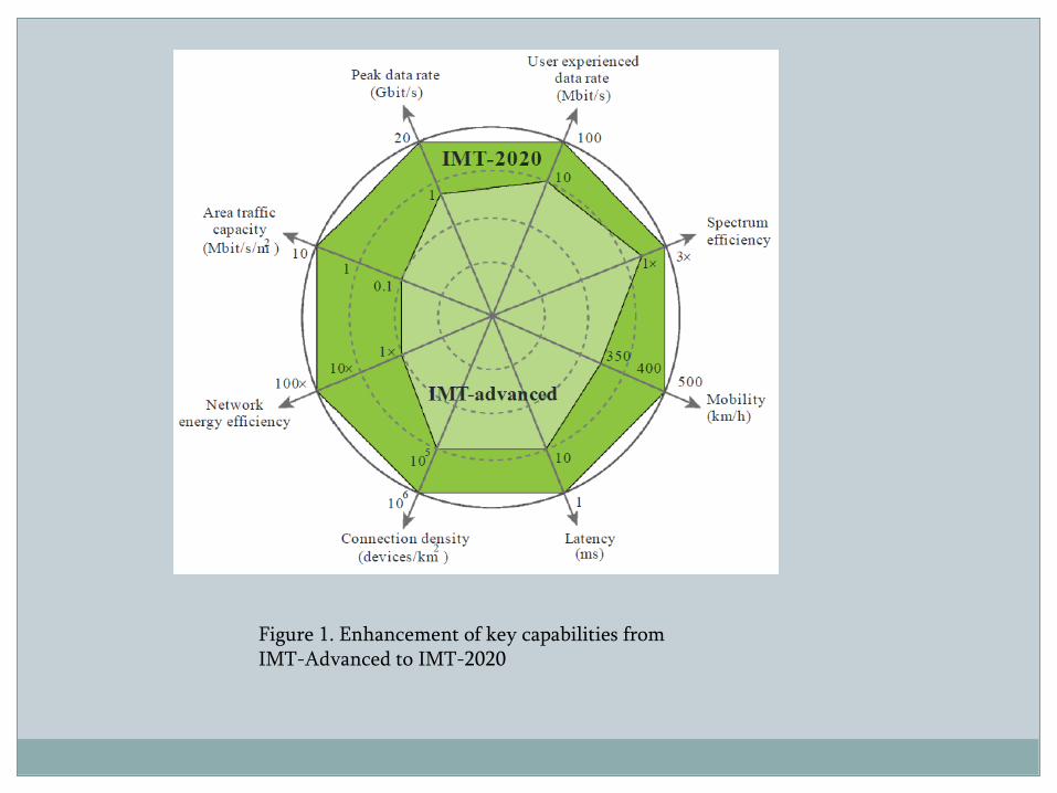
Figure 1. Enhancement of key capabilities from IMT-Advanced to IMT-2020
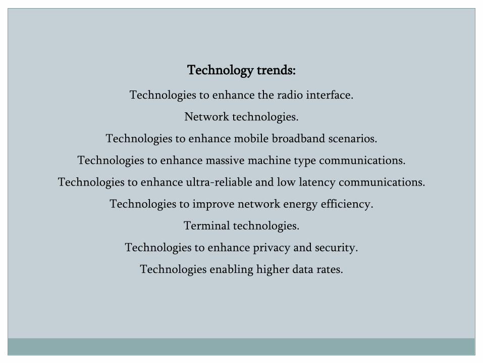
Technology trends:
Technologies to enhance the radio interface.
Network technologies.
Technologies to enhance mobile broadband scenarios.
Technologies to enhance massive machine type communications.
Technologies to enhance ultra-reliable and low latency communications.
Technologies to improve network energy efficiency.
Terminal technologies.
Technologies to enhance privacy and security.
Technologies enabling higher data rates.
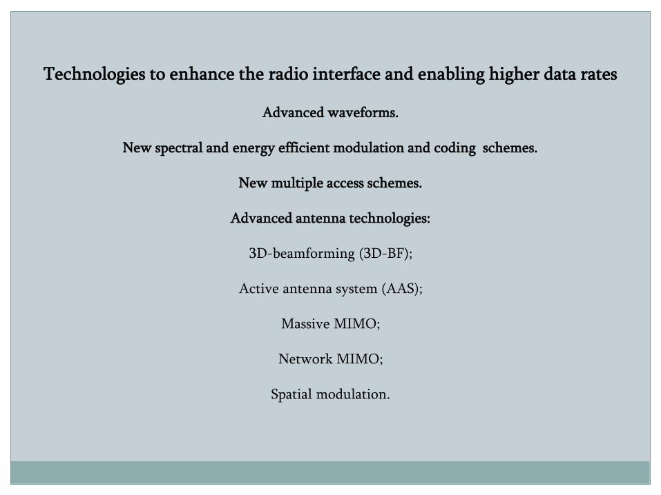
Technologies to enhance the radio interface and enabling higher data rates
Advanced waveforms.
New spectral and energy efficient modulation and coding schemes.
New multiple access schemes.
Advanced antenna technologies:
3D-beamforming (3D-BF);
Active antenna system (AAS);
Massive MIMO;
Network MIMO;
Spatial modulation.
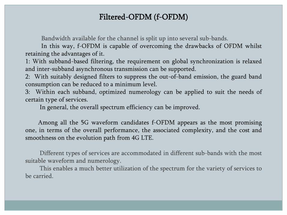
Filtered-OFDM (f-OFDM)
Bandwidth available for the channel is split up into several sub-bands.In this way, f-OFDM is capable of overcoming the drawbacks of OFDM whilst
retaining the advantages of it.1: With subband-based filtering, the requirement on global synchronization is relaxedand inter-subband asynchronous transmission can be supported.2: With suitably designed filters to suppress the out-of-band emission, the guard bandconsumption can be reduced to a minimum level.3: Within each subband, optimized numerology can be applied to suit the needs ofcertain type of services.
In general, the overall spectrum efficiency can be improved.
Among all the 5G waveform candidates f-OFDM appears as the most promisingone, in terms of the overall performance, the associated complexity, and the cost andsmoothness on the evolution path from 4G LTE.
Different types of services are accommodated in different sub-bands with the mostsuitable waveform and numerology.
This enables a much better utilization of the spectrum for the variety of services tobe carried.
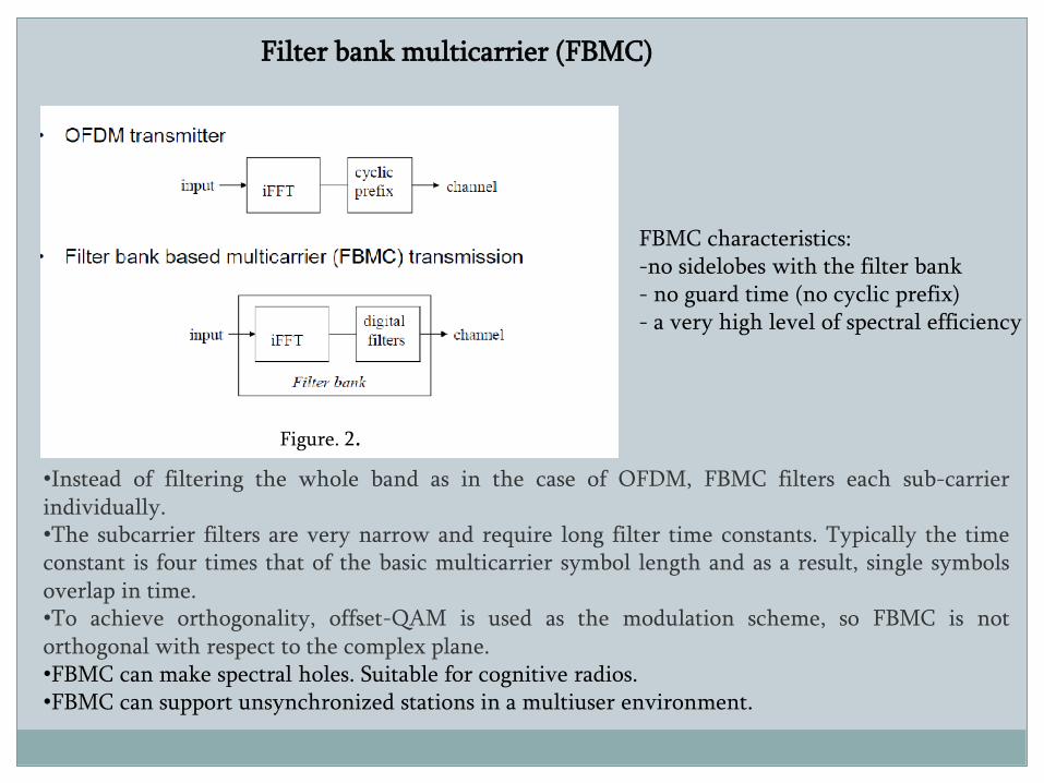
Filter bank multicarrier (FBMC)
FBMC characteristics:-no sidelobes with the filter bank- no guard time (no cyclic prefix)- a very high level of spectral efficiency
Figure. 2.
•Instead of filtering the whole band as in the case of OFDM, FBMC filters each sub-carrierindividually.•The subcarrier filters are very narrow and require long filter time constants. Typically the timeconstant is four times that of the basic multicarrier symbol length and as a result, single symbolsoverlap in time.•To achieve orthogonality, offset-QAM is used as the modulation scheme, so FBMC is notorthogonal with respect to the complex plane.•FBMC can make spectral holes. Suitable for cognitive radios.•FBMC can support unsynchronized stations in a multiuser environment.
Multiple access (MA) technique - major building block of the cellular systems.
The users can simultaneously access the physical medium and share the finite resources of
the system, such as spectrum, time and power.
MA techniques:
- Time Division Multiple Access (TDMA);
- Frequency Division Multiple Access (FDMA);
- Orthogonal Frequency Division Multiple Access (OFDMA);
- Code Division Multiple Access (CDMA).
There are many factors that determine the efficiency of the MA technique such as
spectral efficiency, low complexity implementation, low envelope fluctuations.
MA techniques: Orthogonal and Non-orthogonal MA.
In orthogonal MA techniques, the signal dimension is partitioned and allocated exclusively
to the users, and there is no Multiple Access Interference (MAI).
For non-orthogonal MA (NOMA) techniques, all the users share the entire signal
dimension, and there is a MAI. Thus, for non-orthogonal transmission, more complicated
receiver is required to deal with the MAI comparing to orthogonal transmission.
Non-orthogonal MA is more practical in the uplink scenario because the base station can
afford the Multiuser Detection (MUD) complexity. On the other hand, for downlink,
orthogonal MA is more suitable due to the limited processing power at the user equipment.
Many non-orthogonal MA techniques have been overlooked due to the implementation
complexity. Evidently, the recent advancements in signal processing have opened up new
possibilities for developing more sophisticated and efficient MA techniques: NOMA (low-
density spreading); NOMA (sparse code multiple access); NOMA (pattern division multiple
access).
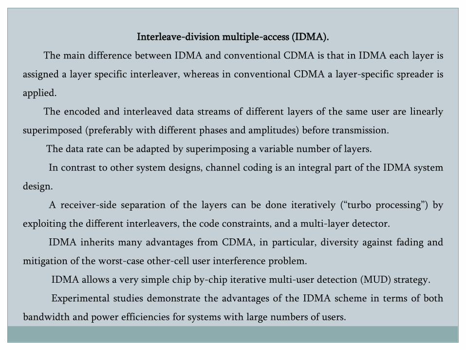
Interleave-division multiple-access (IDMA).
The main difference between IDMA and conventional CDMA is that in IDMA each layer is
assigned a layer specific interleaver, whereas in conventional CDMA a layer-specific spreader is
applied.
The encoded and interleaved data streams of different layers of the same user are linearly
superimposed (preferably with different phases and amplitudes) before transmission.
The data rate can be adapted by superimposing a variable number of layers.
In contrast to other system designs, channel coding is an integral part of the IDMA system
design.
A receiver-side separation of the layers can be done iteratively (“turbo processing”) by
exploiting the different interleavers, the code constraints, and a multi-layer detector.
IDMA inherits many advantages from CDMA, in particular, diversity against fading and
mitigation of the worst-case other-cell user interference problem.
IDMA allows a very simple chip by-chip iterative multi-user detection (MUD) strategy.
Experimental studies demonstrate the advantages of the IDMA scheme in terms of both
bandwidth and power efficiencies for systems with large numbers of users.
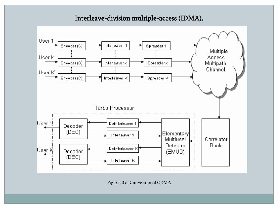
Interleave-division multiple-access (IDMA).
Figure. 3.a. Conventional CDMA
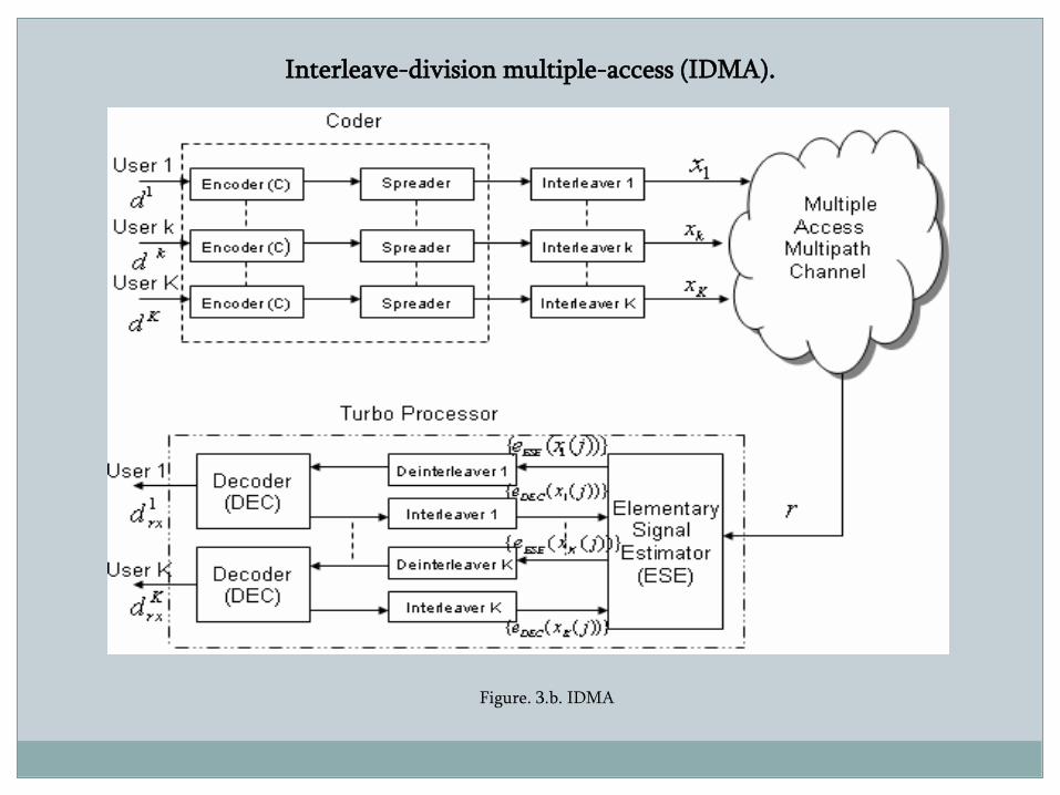
Interleave-division multiple-access (IDMA).
Figure. 3.b. IDMA
1. M. Gabrowska, M. Bossert, and S. Shavgulidze, and S. Schober. “Serially concatenatedspace time convolutional codes and continuous phase modulation.” IEEE Transactions onCommunications, Vol. 56, No. 9, September 2008. P. 1442-1450.
Space-time codes (STC) aim to achieve diversity gain and coding gain, by usingthe spatial and the time domain for transmission. The information is transmitted overmultiple antennas to provide spatial diversity and over multiple time slots to achieve codinggain.
The radio frequency spectrum is a limited natural resource. Therefore digitalsatellite communication, digital radio links and digital land mobile radio schemes shoulduse as little bandwidth as possible. For many applications, the power is also a limitedresource. Therefore, it is advantageous to have a modulation method, which is both powerand bandwidth efficient. A third requirement for many applications is constant amplitude.
Continuous phase modulation (CPM) can be considered as an efficient constantamplitude modulation scheme with memory that simultaneously have narrow mainlobe,low spectral sidelobs and good power efficiency. CPM is a non-linear modulation that isdefined by a phase trellis. CPM’s constant envelope provides good power efficiency, andthe maintained phase continuity can provide good spectral efficiency.
When CPM is combined with STC good performances may be expected.
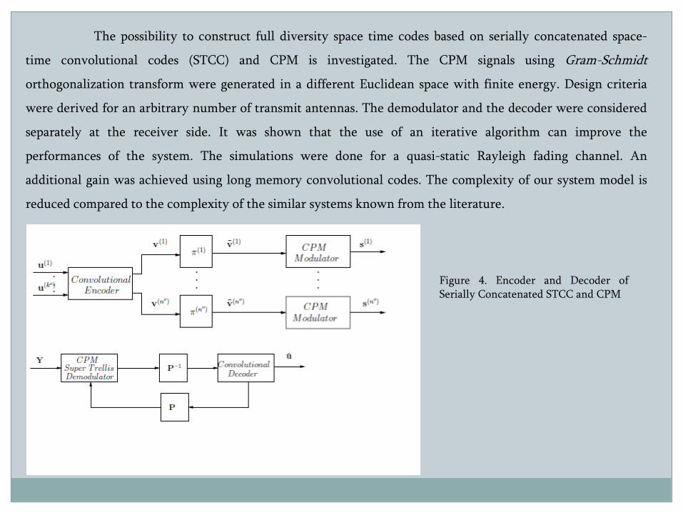
The possibility to construct full diversity space time codes based on serially concatenated space-
time convolutional codes (STCC) and CPM is investigated. The CPM signals using Gram-Schmidt
orthogonalization transform were generated in a different Euclidean space with finite energy. Design criteria
were derived for an arbitrary number of transmit antennas. The demodulator and the decoder were considered
separately at the receiver side. It was shown that the use of an iterative algorithm can improve the
performances of the system. The simulations were done for a quasi-static Rayleigh fading channel. An
additional gain was achieved using long memory convolutional codes. The complexity of our system model is
reduced compared to the complexity of the similar systems known from the literature.
Figure 4. Encoder and Decoder ofSerially Concatenated STCC and CPM
2. J. Freudenberger, F. Ghaboussi, and S. Shavgulidze, “New coding techniques for codesover Gaussian integers,” IEEE Transactions on Communications, Vol. 61, No. 8, August 2013.P. 3114-3124.
Gaussian integers are a subset of the complex numbers such that the real andimaginary parts are integers. Codes over Gaussian integers can be used for coding over two-dimensional signal spaces, e.g. using quadrature-amplitude modulation (QAM).
This work considers codes over finite sets of Gaussian integers. We have shownthat OMEC codes, product codes, and Plotkin codes can be constructed for Gaussian integerfields as well as for rings. Gaussian integer rings extend the possible complex signalconstellations for codes over Gaussian integers. Moreover, binary information vectors caneasily be encoded.
We have demonstrated that set partitioning for Gaussian integers is possible. Thepartitioning of rings does not alter the algebraic properties of the set. The set partitioningenables multilevel code constructions. We have constructed simple codes that illustrate thecode construction. Multiple error correcting codes can be constructed when all partitionlevels are protected by outer codes.
We think that this is a promising direction for further research.
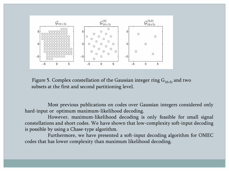
Figure 5. Complex constellation of the Gaussian integer ring G10+5i and two
subsets at the first and second partitioning level.
Most previous publications on codes over Gaussian integers considered onlyhard-input or optimum maximum-likelihood decoding.
However, maximum-likelihood decoding is only feasible for small signalconstellations and short codes. We have shown that low-complexity soft-input decodingis possible by using a Chase-type algorithm.
Furthermore, we have presented a soft-input decoding algorithm for OMECcodes that has lower complexity than maximum likelihood decoding.
A Gaussian integer is a complex number whose real and imaginary parts are bothintegers.
Likewise a Lipschitz integer is a quaternion whose components are all integers.Based on the modulo function for Lipschitz integers it is possible to define residual class rings(quotient rings) of Lipschitz integers that have a finite number of elements. Coding over suchquotient rings of Lipschitz integers has recently attracted some attention.
Some of these code constructions are generalizations of coding techniquesdeveloped for Gaussian integers.
Other examples for codes over quaternions are the constructions for Hurwitzintegers and codes over quaternions, where the elements are from the commutative ring ofeven integers.
Forney and Wei proposed the constellation figure of merit (CFM) to comparesignal constellations of different dimensions. The CFM is the ratio of the minimum squaredEuclidean distance and the average energy per two-dimensions. Two constellations that havethe same CFM have similar error probabilities for high signal to noise ratios (SNR). Gaussianintegers and Lipschitz Integers can be compared by means of the CFM.
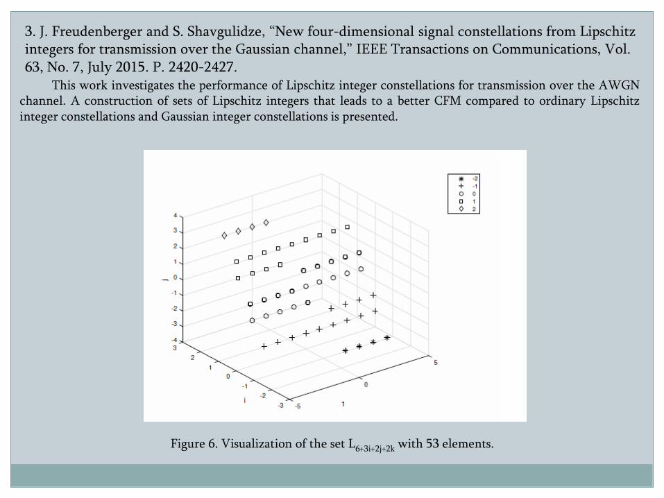
3. J. Freudenberger and S. Shavgulidze, “New four-dimensional signal constellations from Lipschitz integers for transmission over the Gaussian channel,” IEEE Transactions on Communications, Vol. 63, No. 7, July 2015. P. 2420-2427.
This work investigates the performance of Lipschitz integer constellations for transmission over the AWGNchannel. A construction of sets of Lipschitz integers that leads to a better CFM compared to ordinary Lipschitzinteger constellations and Gaussian integer constellations is presented.
Figure 6. Visualization of the set L6+3i+2j+2k with 53 elements.
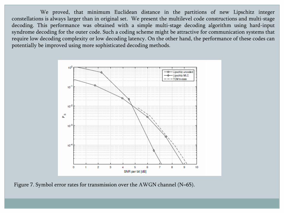
We proved, that minimum Euclidean distance in the partitions of new Lipschitz integerconstellations is always larger than in original set. We present the multilevel code constructions and multi-stagedecoding. This performance was obtained with a simple multi-stage decoding algorithm using hard-inputsyndrome decoding for the outer code. Such a coding scheme might be attractive for communication systems thatrequire low decoding complexity or low decoding latency. On the other hand, the performance of these codes canpotentially be improved using more sophisticated decoding methods.
Figure 7. Symbol error rates for transmission over the AWGN channel (N=65).
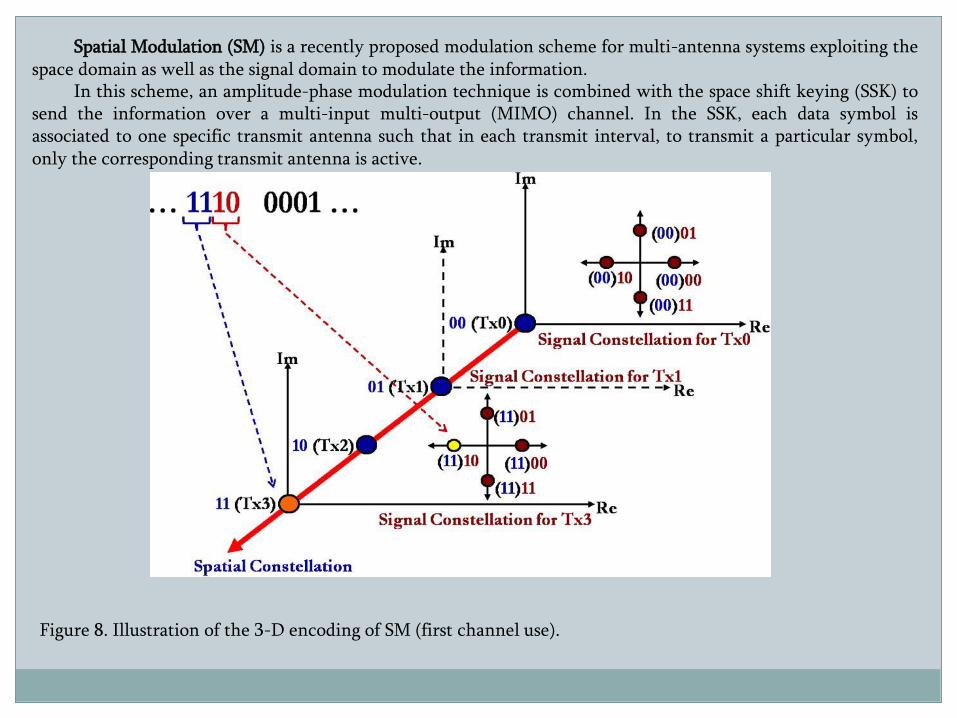
Spatial Modulation (SM) is a recently proposed modulation scheme for multi-antenna systems exploiting thespace domain as well as the signal domain to modulate the information.
In this scheme, an amplitude-phase modulation technique is combined with the space shift keying (SSK) tosend the information over a multi-input multi-output (MIMO) channel. In the SSK, each data symbol isassociated to one specific transmit antenna such that in each transmit interval, to transmit a particular symbol,only the corresponding transmit antenna is active.
Figure 8. Illustration of the 3-D encoding of SM (first channel use).
Several benefits of SSK and SM transmission and their advantages over traditionalMIMO transmission schemes have been addressed in the literature.
•The low transmission/reception complexity of these transmission techniques makes them asuitable candidate for future wireless systems especially when the number of antennas at thetransmitter is large. For example, SSK/SM can be considered as a technique applicable tomassive MIMO communication to support high dimension modulation.•Having many antennas at the transmitter, enables modulating information via space whichcan increase the rate significantly while only using one RF chain at the transmitter to avoidcomplexity.•SM is capable of dispensing with the requirement of multiple Radio Frequency (RF) chains,therefore relaxing the Inter-Antenna-Synchronization (IAS) specifications, whilst mitigatingthe Inter Antenna Interference (IAI) of conventional MIMO techniques. Additionally, thesingle-RF design is capable of reducing the total power consumption.•Only a single power amplifier is needed for implementing SM-MIMO systems, which istypically responsible for the vast majority of power dissipation at the transmitter.• It may be flexibly configured for diverse transmit and receive antenna constellations,especially for the challenging scenario of asymmetric/unbalanced MIMO systems.
On-going Research:Signal Constellation Design for SM. Coded SM. A Low-complexity Detection scheme for SM. High rate spatial modulation for multiuser systems.
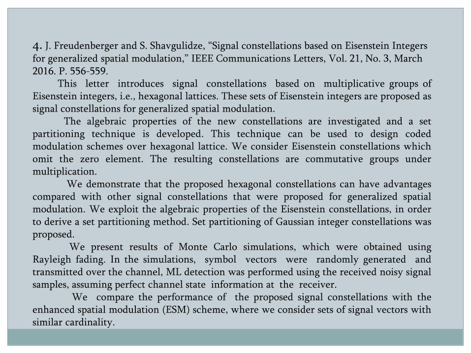
4. J. Freudenberger and S. Shavgulidze, “Signal constellations based on Eisenstein Integers for generalized spatial modulation,” IEEE Communications Letters, Vol. 21, No. 3, March 2016. P. 556-559.
This letter introduces signal constellations based on multiplicative groups ofEisenstein integers, i.e., hexagonal lattices. These sets of Eisenstein integers are proposed assignal constellations for generalized spatial modulation.
The algebraic properties of the new constellations are investigated and a setpartitioning technique is developed. This technique can be used to design codedmodulation schemes over hexagonal lattice. We consider Eisenstein constellations whichomit the zero element. The resulting constellations are commutative groups undermultiplication.
We demonstrate that the proposed hexagonal constellations can have advantagescompared with other signal constellations that were proposed for generalized spatialmodulation. We exploit the algebraic properties of the Eisenstein constellations, in orderto derive a set partitioning method. Set partitioning of Gaussian integer constellations wasproposed.
We present results of Monte Carlo simulations, which were obtained usingRayleigh fading. In the simulations, symbol vectors were randomly generated andtransmitted over the channel, ML detection was performed using the received noisy signalsamples, assuming perfect channel state information at the receiver.
We compare the performance of the proposed signal constellations with theenhanced spatial modulation (ESM) scheme, where we consider sets of signal vectors withsimilar cardinality.
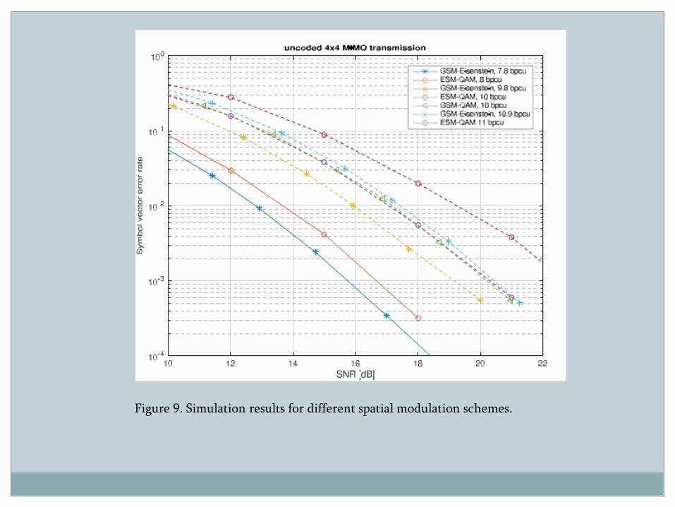
Figure 9. Simulation results for different spatial modulation schemes.
Figure 10. Simulation results for proposed encoded spatial modulation scheme.